![image](https://cdn-mineru.openxlab.org.cn/result/2026-05-27/878f926e-6587-4767-a01e-239a74a4d897/7e04b37f487e39bf1520d4b5d1769e85a29bd24ff1f79436d208afe622e53ea2.jpg)


# IEEE

  IEEE Standard for Local and metropolitan area networks—

# Virtual Bridged Local Area Networks

  Amendment 12: Forwarding and Queuing Enhancements for Time-Sensitive Streams

# IEEE Computer Society

  Sponsored by the

  LAN/MAN Standards Committee

# IEEE Standard for

# Local and metropolitan area networks—

# Virtual Bridged Local Area Networks

# Amendment 12: Forwarding and Queuing Enhancements for Time-Sensitive Streams

  Sponsor

  LAN/MAN Standards Committee

  of the

  IEEE Computer Society

  Approved 9 December 2009

  IEEE-SA Standards Board

  Abstract: This amendment to IEEE Std 802.1Q defines enhancements to the forwarding and queueing functions of a VLAN Bridge to support the transmission of time-sensitive data streams.

  Keywords: Bridged Local Area Networks, local area networks (LANs), MAC Bridges, metropolitan area networks, time-sensitive data streams, Virtual Bridged Local Area Networks (virtual LANs)

  The Institute of Electrical and Electronics Engineers, Inc. 3 Park Avenue, New York, NY 10016-5997, USA

  Copyright © 2010 by the Institute of Electrical and Electronics Engineers, Inc. All rights reserved. Published 5 January 2010. Printed in the United States of America.

  IEEE and 802 are registered trademarks in the U.S. Patent & Trademark Office, owned by The Institute of Electrical and Electronics Engineers, Incorporated.

  PDF: ISBN 978-0-7381-6143-3 STD96007 Print: ISBN 978-0-7381-6144-0 STDPD96007

  No part of this publication may be reproduced in any form, in an electronic retrieval system or otherwise, without the prior written permission of the publisher.

  IEEE Standards documents are developed within the IEEE Societies and the Standards Coordinating Committees of the IEEE Standards Association (IEEE-SA) Standards Board. The IEEE develops its standards through a consensus development process, approved by the American National Standards Institute, which brings together volunteers representing varied viewpoints and interests to achieve the final product. Volunteers are not necessarily members of the Institute and serve without compensation. While the IEEE administers the process and establishes rules to promote fairness in the consensus development process, the IEEE does not independently evaluate, test, or verify the accuracy of any of the information or the soundness of any judgments contained in its standards.

  Use of an IEEE Standard is wholly voluntary. The IEEE disclaims liability for any personal injury, property or other damage, of any nature whatsoever, whether special, indirect, consequential, or compensatory, directly or indirectly resulting from the publication, use of, or reliance upon this, or any other IEEE Standard document.

  The IEEE does not warrant or represent the accuracy or content of the material contained herein, and expressly disclaims any express or implied warranty, including any implied warranty of merchantability or fitness for a specific purpose, or that the use of the material contained herein is free from patent infringement. IEEE Standards documents are supplied “AS IS.”

  The existence of an IEEE Standard does not imply that there are no other ways to produce, test, measure, purchase, market, or provide other goods and services related to the scope of the IEEE Standard. Furthermore, the viewpoint expressed at the time a standard is approved and issued is subject to change brought about through developments in the state of the art and comments received from users of the standard. Every IEEE Standard is subjected to review at least every five years for revision or reaffirmation, or every ten years for stabilization. When a document is more than five years old and has not been reaffirmed, or more than ten years old and has not been stabilized, it is reasonable to conclude that its contents, although still of some value, do not wholly reflect the present state of the art. Users are cautioned to check to determine that they have the latest edition of any IEEE Standard.

  In publishing and making this document available, the IEEE is not suggesting or rendering professional or other services for, or on behalf of, any person or entity. Nor is the IEEE undertaking to perform any duty owed by any other person or entity to another. Any person utilizing this, and any other IEEE Standards document, should rely upon the advice of a competent professional in determining the exercise of reasonable care in any given circumstances.

  Interpretations: Occasionally questions may arise regarding the meaning of portions of standards as they relate to specific applications. When the need for interpretations is brought to the attention of IEEE, the Institute will initiate action to prepare appropriate responses. Since IEEE Standards represent a consensus of concerned interests, it is important to ensure that any interpretation has also received the concurrence of a balance of interests.For this reason, IEEE and the members of its societies and Standards Coordinating Committees are not able to provide an instant response to interpretation requests except in those cases where the matter has previously received formal consideration. A statement, written or oral, that is not processed in accordance with the IEEE-SA Standards Board Operations Manual shall not be considered the official position of IEEE or any of its committees and shall not be considered to be, nor be relied upon as, a formal interpretation of the IEEE.At lectures, symposia, seminars, or educational courses, an individual presenting information on IEEE standards shall make it clear that his or her views should be considered the personal views of that individual rather than the formal position, explanation, or interpretation of the IEEE. Comments for revision of IEEE Standards are welcome from any interested party, regardless of membership affiliation with IEEE. Suggestions for changes in documents should be in the form of a proposed change of text, together with appropriate supporting comments. Recommendations to change the status of a stabilized standard should include a rationale as to why a revision or withdrawal is required.

  Comments and recommendations on standards, and requests for interpretations should be addressed to:

  Secretary, IEEE-SA Standards Board

  445 Hoes Lane

  Piscataway, NJ 08854

  USA

  Authorization to photocopy portions of any individual standard for internal or personal use is granted by the Institute of Electrical and Electronics Engineers, Inc., provided that the appropriate fee is paid to Copyright Clearance Center. To arrange for payment of licensing fee, please contact Copyright Clearance Center, Customer Service, 222 Rosewood Drive, Danvers, MA 01923 USA; +1 978 750 8400. Permission to photocopy portions of any individual standard for educational classroom use can also be obtained through the Copyright Clearance Center.

# Introduction

  This introduction is not part of IEEE Std 802.1Qav-2009, IEEE Standards for Local and Metropolitan Area Networks—Virtual Bridged Local Area Networks—Amendment 12: Forwarding and Queuing Enhancements for Time-Sensitive Streams.

# Notice to users

# Laws and regulations

  Users of these documents should consult all applicable laws and regulations. Compliance with the provisions of this standard does not imply compliance to any applicable regulatory requirements. Implementers of the standard are responsible for observing or referring to the applicable regulatory requirements. IEEE does not, by the publication of its standards, intend to urge action that is not in compliance with applicable laws, and these documents may not be construed as doing so.

# Copyrights

  This document is copyrighted by the IEEE. It is made available for a wide variety of both public and private uses. These include both use, by reference, in laws and regulations, and use in private self-regulation, standardization, and the promotion of engineering practices and methods. By making this document available for use and adoption by public authorities and private users, the IEEE does not waive any rights in copyright to this document.

# Updating of IEEE documents

  Users of IEEE standards should be aware that these documents may be superseded at any time by the issuance of new editions or may be amended from time to time through the issuance of amendments, corrigenda, or errata. An official IEEE document at any point in time consists of the current edition of the document together with any amendments, corrigenda, or errata then in effect. In order to determine whether a given document is the current edition and whether it has been amended through the issuance of amendments, corrigenda, or errata, visit the IEEE Standards Association website at http://ieeexplore.ieee.org/xpl/standards.jsp, or contact the IEEE at the address listed previously.

  For more information about the IEEE Standards Association or the IEEE standards development process, visit the IEEE-SA website at http://standards.ieee.org.

# Errata

  Errata, if any, for this and all other standards can be accessed at the following URL: http:// standards.ieee.org/reading/ieee/updates/errata/index.html. Users are encouraged to check this URL for errata periodically.

# Interpretations

  Current interpretations can be accessed at the following URL: http://standards.ieee.org/reading/ieee/interp/ index.html.

# Patents

  Attention is called to the possibility that implementation of this amendment may require use of subject matter covered by patent rights. By publication of this amendment, no position is taken with respect to the existence or validity of any patent rights in connection therewith. The IEEE is not responsible for identifying Essential Patent Claims for which a license may be required, for conducting inquiries into the legal validity or scope of Patents Claims or determining whether any licensing terms or conditions provided in connection with submission of a Letter of Assurance, if any, or in any licensing agreements are reasonable or nondiscriminatory. Users of this amendment are expressly advised that determination of the validity of any patent rights, and the risk of infringement of such rights, is entirely their own responsibility. Further information may be obtained from the IEEE Standards Association.

# Participants

  At the time this amendment was submitted to the IEEE-SA for approval, the IEEE 802.1 Working Group had the following membership:

  Tony Jeffree, Chair

  Paul Congdon, Vice Chair

  Michael Johas Teener, Chair, AV Bridging Task Group

<table><tr><td>Zehavit Alon</td><td>Charles Hudson</td><td>David Peterson</td></tr><tr><td>Siamack Ayandeh</td><td>Romain Insler</td><td>Hayim Porat</td></tr><tr><td>Jan Bialkowski</td><td>Abhay Karandikar</td><td>Max Pritikin</td></tr><tr><td>Rob Boatright</td><td>Prakash Kashyap</td><td>Karen Randall</td></tr><tr><td>Jean-Michel Bonnamy</td><td>Hal Keen</td><td>Josef Roese</td></tr><tr><td>Paul Bottorff</td><td>Keti Kilcrease</td><td>Derek J. Rohde</td></tr><tr><td>Rudolf Brandner</td><td>Doyeon Kim</td><td>Dan Romascanu</td></tr><tr><td>Craig W. Carlson</td><td>Yongbum Kim</td><td>Jessy V. Rouyer</td></tr><tr><td>Weiying Cheng</td><td>Philippe Klein</td><td>Jonathan Sadler</td></tr><tr><td>Rao Cherukuri</td><td>Mike Ko</td><td>Ali Sajassi</td></tr><tr><td>Jin-Seek Choi</td><td>Vinod Kumar</td><td>Panagiotis Saltsidis</td></tr><tr><td>Diego Crupnicoff</td><td>Bruce Kwan</td><td>Joseph Salowey</td></tr><tr><td>Claudio Desanti</td><td>Kari Laihonen</td><td>Satish Sathe</td></tr><tr><td>Zhemin Ding</td><td>Ashvin Lakshmikantha</td><td>John Sauer</td></tr><tr><td>Linda Dunbar</td><td>Michael Lerer</td><td>Michael Seaman</td></tr><tr><td>Hesham M. Elbakoury</td><td>Marina Lipshteyn</td><td>Koichiro Seto</td></tr><tr><td>David Elie-Dit-Cosaque</td><td>Gael Mace</td><td>Himanshu Shah</td></tr><tr><td>Janos Farkas</td><td>Ben Mack-Crane</td><td>Nurit Sprecher</td></tr><tr><td>Donald Fedyk</td><td>David Martin</td><td>Kevin B. Stanton</td></tr><tr><td>Norman Finn</td><td>Alan McGuire</td><td>Robert A. Sultan</td></tr><tr><td>Robert Frazier</td><td>James McIntosh</td><td>Muneyoshi Suzuki</td></tr><tr><td>John Fuller</td><td>Menucher Menuchery</td><td>Patricia Thaler</td></tr><tr><td>Geoffrey Garner</td><td>Gabriel Montenegro</td><td>Oliver Thorp</td></tr><tr><td>Anoop Ghanwani</td><td>Matthew Mora</td><td>Manoj Wadekar</td></tr><tr><td>Franz Goetz</td><td>John Morris</td><td>Yuehua Wei</td></tr><tr><td>Yannick Le Goff</td><td>Eric Multanen</td><td>Brian Weis</td></tr><tr><td>Eric Gray</td><td>Kevin Nolish</td><td>Martin White</td></tr><tr><td>Karanvir Grewal</td><td>Don O’Connor</td><td>Bert Wijnen</td></tr><tr><td>Craig Gunther</td><td>David Olsen</td><td>Michael D. Wright</td></tr><tr><td>Mitch Gusat</td><td>Donald Pannell</td><td>Chien-Hsien Wu</td></tr><tr><td>Stephen Haddock</td><td>Glenn Parsons</td><td>Ken Young</td></tr><tr><td>Asif Hazarika</td><td>Joseph Pelissier</td><td>Glen Zorn</td></tr></table>

  The following members of the individual balloting committee voted on this standard. Balloters may have voted for approval, disapproval, or abstention.

<table><tr><td>Thomas Alexander</td><td>C. Guy</td><td>Benjamin Rolfe</td></tr><tr><td>Butch Anton</td><td>Stephen Haddock</td><td>Randall Safier</td></tr><tr><td>Khin Mi Mi Aung</td><td>John Harauz</td><td>John Sargent</td></tr><tr><td>Hugh Barrass</td><td>John Hawkins</td><td>John Sauer</td></tr><tr><td>Robert Boatright</td><td>C. Huntly</td><td>Peter Saunderson</td></tr><tr><td>Tomo Bogataj</td><td>Atsushi Ito</td><td>Bartien Sayogo</td></tr><tr><td>Edward Carley</td><td>Raj Jain</td><td>Michael Seaman</td></tr><tr><td>James Carlo</td><td>Tony Jeffree</td><td>Suman Sharma</td></tr><tr><td>Juan Carreon</td><td>Shinkyo Kaku</td><td>Gil Shultz</td></tr><tr><td>Keith Chow</td><td>Piotr Karocki</td><td>Kapil Sood</td></tr><tr><td>Charles Cook</td><td>Stuart J. Kerry</td><td>Amjad Soomro</td></tr><tr><td>Thomas Dineen</td><td>Yongbum Kim</td><td>Kevin B. Stanton</td></tr><tr><td>Linda Dunbar</td><td>Shen Loh</td><td>Thomas Starai</td></tr><tr><td>Sourav Dutta</td><td>William Lumpkins</td><td>Walter Struppler</td></tr><tr><td>David Elie-Dit-Cosaque</td><td>G. Luri</td><td>Robert Sultan</td></tr><tr><td>Donald Fedyk</td><td>Peter Martini</td><td>Joseph Tardo</td></tr><tr><td>C. Fitzgerald</td><td>Jonathon Mclendon</td><td>William Taylor</td></tr><tr><td>Prince Francis</td><td>Gary Michel</td><td>Michael Johas Teener</td></tr><tr><td>Yukihiro Fujimoto</td><td>Jose Morales</td><td>Patricia Thaler</td></tr><tr><td>John Fuller</td><td>Michael S. Newman</td><td>Geoffrey Thompson</td></tr><tr><td>Venkatasubramaniyan Ganesan</td><td>Nick S. A. Nikjoo</td><td>Mark-Rene Uchida</td></tr><tr><td>Geoffrey Garner</td><td>Paul Nikolich</td><td>Prabodh Varshney</td></tr><tr><td>Devon Gayle</td><td>Satoshi Obara</td><td>Niel Warren</td></tr><tr><td>James Gilb</td><td>David Olsen</td><td>Stephen Webb</td></tr><tr><td>Randall Groves</td><td>Hayim Porat</td><td>Kunpeng Wu</td></tr><tr><td>Robert M. Grow</td><td>June-Koo Rhee</td><td>Oren Yuen</td></tr><tr><td>Craig Gunther</td><td>Robert Robinson</td><td></td></tr></table>

  When the IEEE-SA Standards Board approved this standard on 9 December 2009, it had the following membership:

  Robert M. Grow, Chair

  Thomas Prevost, Vice Chair

  Steve M. Mills, Past Chair

  Judith Gorman, Secretary

  John Barr

  Karen Bartleson

  Victor Berman

  Ted Burse

  Richard DeBlasio

  Andy Drozd

  Mark Epstein

  Alexander Gelman

  Jim Hughes

  Richard H. Hulett

  Young Kyun Kim

  Joseph L. Koepfinger*

  John Kulick

  David J. Law

  Glenn Parsons

  Ronald C. Petersen

  Narayanan Ramachandran

  Jon Walter Rosdahl

  Sam Sciacca

  *Member Emeritus

  Also included are the following nonvoting IEEE-SA Standards Board liaisons:

  Howard L. Wolfman, TAB Representative

  Michael Janezic, NIST Representative

  Satish K. Aggarwal, NRC Representative

  Michelle Turner

  IEEE Standards Program Manager, Document Development

  Kathryn Cush

  IEEE Standards Program Manager, Technical Program Development

# Contents

1. Overview.. . 2

  1.1 Scope... . 2

2. Normative references. 3

3. Definitions . 5

4. Abbreviations.....

5. Conformance.. 9

  5.19 End station requirements—forwarding and queuing for time-sensitive streams.. 9

6. Support of the MAC service . . 11

  6.6 Internal Sublayer Service... 11

  6.9 Support of the EISS . 11

8. Principles of bridge operation.. . 15

  8.6 The Forwarding Process . . 15

  8.8 The Filtering Database.... . 18

12. Bridge management .... . 25

  12.21 Management entities for forwarding and queueing for time-sensitive streams.. . 25

17. Management protocol . . 27

  17.2 Structure of the MIB . . 27

  17.3 Relationship to other MIBs.. . 28

  17.4 Security considerations ..... . 28

  17.7 MIB modules . . 29

34. Forwarding and queuing for time-sensitive streams.... .. 41

  34.1 Overview.... . 41

  34.2 Detection of SRP domains. . 41

  34.3 The bandwidth availability parameters.... . 42

  34.4 Deriving actual bandwidth requirements from the size of the MSDU . . 43

  34.5 Mapping priorities to traffic classes for time-sensitive streams . . 44

  34.6 End station behavior . . 46

Annex A (normative) PICS proforma—Bridge implementations . . 49

  A.5 Major capabilities . . 49

  A.14 Bridge management . . 49

  A.24 Management Information Base (MIB) . . 49

  A.31 Forwarding and queuing for time-sensitive streams.. . 50

Annex H (informative) Bibliography . .. 51

Annex I (normative) PICS proforma—End station implementations . .. 53

  I.5 Major capabilities . . 53

  I.9 Forwarding and queuing for time-sensitive streams.. . 54

Annex L (informative) Operation of the credit-based shaper algorithm . 55

  L.1 Overview of credit-based shaper operation . .. 55

  L.2 “Class measurement intervals” in Bridges.. . 59

  L.3 Determining worst-case latency contribution and buffering requirements . 60

  L.4 Operation of the credit-based shaper in a coordinated shared network . . 71

# Figures

  Figure 34-1 Queuing model for a Talker station . 46

  Figure L-1 Credit-based shaper operation—no conflicting traffic.. 5 7

  Figure L-2 Credit-based shaper operation–conflicting traffic.. 58

  Figure L-3 Credit-based shaper operation—burst traffic . 5 9

  Figure L-4 Interference and latency . 6 3

  Figure L-5 Burst behavior and credit . 63

  Figure L-6 Fan-in scenario. 67

  Figure L-7 Permanent delay scenario.. 6 8

  Figure L-8 Building up buffer occupancy - 1 .. 69

  Figure L-9 Building up buffer occupancy - 2 . 69

  Figure L-10 Building up buffer occupancy - 3 . 69

  Figure L-11 Building up buffer occupancy - 4 . 70

# Tables

  Table 6-5 Priority regeneration . 1 2

  Table 6-6 Default SRP domain boundary port priority regeneration override values . 12

  Table 8-3 Recommended priority to traffic class mappings .. 15

  Table 8-4 Transmission selection algorithm identifiers ...... 16

  Table 8-5 Combining Static and Dynamic Filtering Entries for an individual MAC Address ............. 21

  Table 8-6 Combining Static Filtering Entry and MAC Address Registration Entry for “All Group Addresses” and “All Unregistered Group Addresses” 2 2

  Table 8-7 Forwarding or Filtering for specific group MAC Addresses.. 2 3

  Table 8-8 Forwarding or Filtering with Dynamic Reservation Entries . 24

  Table 12-1 Bandwidth Availability Parameter Table row elements .. 2 5

  Table 12-2 Transmission Selection Algorithm Table row elements. 2 6

  Table 12-3 Priority Regeneration Override Table row elements .. 2 6

  Table 17-1 Structure of the MIB modules . 27

  Table 17-18 FQTSS MIB structure and object cross reference .. 2 8

  Table 34-1 Recommended priority to traffic class mappings for SR classes A and B . 4 5

  Table 34-2 Recommended priority to traffic class mappings for SR class B only .. 45

# IEEE Standard for

# Local and metropolitan area networks—

# Virtual Bridged Local Area Networks

# Amendment 12: Forwarding and Queuing Enhancements for Time-Sensitive Streams

  IMPORTANT NOTICE: This standard is not intended to ensure safety, security, health, or environmental protection in all circumstances. Implementers of the standard are responsible for determining appropriate safety, security, environmental, and health practices or regulatory requirements.

  This IEEE document is made available for use subject to important notices and legal disclaimers. These notices and disclaimers appear in all publications containing this document and may be found under the heading “Important Notice” or “Important Notices and Disclaimers Concerning IEEE Documents.” They can also be obtained on request from IEEE or viewed at http://standards.ieee.org/IPR/ disclaimers.html.

# Editorial Note

  This amendment specifies changes to the forwarding and queueing functions described in IEEE Std 802.1QTM. Changes are applied to the base text of IEEE Std 802.1Q-2005, as modified by those amendments that had been approved, but not incorporated into the base text of the standard, at the time that this amendment was approved, namely (in chronological order) IEEE Std 802.1adTM, IEEE Std 802.1akTM, IEEE Std 802.1agTM, IEEE Std 802.1ahTM, IEEE Std 802.1Q-2005/Cor 1, IEEE Std 802.1apTM, IEEE Std 802.1QawTM, IEEE Std 802.1QayTM, and IEEE Std 802.1ajTM. Text shown in bold italics in this amendment defines the editing instructions necessary to changes to this base text. Three editing instructions are used: change, delete, and insert. Change is used to make a change to existing material. The editing instruction specifies the location of the change and describes what is being changed. Changes to existing text may be clarified using strikeout markings to indicate removal of old material, and underscore markings to indicate addition of new material. Delete removes existing material. Insert adds new material without changing the existing material. Insertions may require renumbering. If so, renumbering instructions are given in the editing instruction. Editorial notes will not be carried over into future editions of IEEE Std. 802.1Q.

1. Overview

## 1.1 Scope

# Insert the following text at the end of 1.1, renumbering the list items and NOTEs as necessary:

  This standard allows bridges to provide performance guarantees for time-sensitive (i.e., bounded latency and latency variation) loss-sensitive real-time audio video (AV) data stream transmission (AV traffic). It specifies priority regeneration and controlled bandwidth queue draining algorithms. Virtual Local Area Network (VLAN) tag encoded priority values are allocated, in aggregate, to segregate frames among queues that support AV traffic and queues that support non-AV traffic, allowing simultaneous support of both AV traffic and other bridged traffic over and between wired and wireless Local Area Networks (LANs). To this end, it

  a) Defines status parameters that allow the boundaries of a Stream Reservation Protocol (SRP—see Clause 351) domain (6.6.4) to be identified and maintained

  b) Specifies how the priority information in frames received at SRP domain boundary ports is regenerated

  NOTE 1—The priorities in frames transmitted from outside an SRP domain to a Bridge inside an SRP domain are remapped in order to ensure that traffic that is not associated with a reservation does not disrupt traffic that is associated with a reservation. Hence, traffic entering an SRP domain that uses priority code point values associated with reserved traffic classes will be re-mapped to priority code point values that are not associated with reserved traffic classes.2

  c) Specifies how priority information is used to determine the traffic classes to be used for timesensitive streams

  d) Defines a credit-based shaper algorithm to shape traffic in accordance with stream reservations

  NOTE 2—The credit-based shaper algorithm operates on the outbound queues; the mechanisms specified for the support of time-sensitive AV traffic do not involve any form of ingress metering or policing.

# 2 Normative references

  Insert the following references into Clause 2 in appropriate collating sequence:

  IEEE Std 802.1AXTM-2008, IEEE Standard for Local and Metropolitan Area Networks—Link Aggregation.

# 3 Definitions

  Insert the following text immediately after the first paragraph of Clause 3:

  This standard makes use of the following terms defined in IEEE Std 802:

  — end station

  — station

  Insert the following definitions into Clause 3, in alphabetical order, renumbering existing definitions as needed:

  3.1 audio video (AV) traffic: Traffic associated with audio and/or video applications that is sensitive to transmission latency and latency variation, and, for some applications, packet loss.

  3.2 latency: The delay experienced by a frame in the course of its propagation between two points in a network, measured from the time that a known reference point in the frame passes the first point to the time that the reference point in the frame passes the second point.

  NOTE 1—Latency is sometimes referred to as frame delay.

  NOTE 2—The term frame is used in this standard to refer to a data frame, and not to a video frame.

  3.3 stream reservation (SR) class: A traffic class whose bandwidth can be reserved for AV traffic. A priority value is associated with each SR class. SR classes are denoted by consecutive letters of the alphabet, starting with A and continuing for up to seven classes.

  3.4 Stream Reservation Protocol (SRP) domain boundary port: A Port of a station that is a member of an SRP domain for a given SR class, and that is connected via an individual LAN to a Port of a station that is either within a different SRP domain for that SR class, or is not part of any SRP domain.

  NOTE—The term SRP domain is defined in 6.6.4.

  3.5 Stream Reservation Protocol (SRP) domain core port: A Port of a station that is a member of an SRP domain for a given SR class, and that is connected, via an individual LAN that is part of the active topology, to a Port of a station that is a member of the same SRP domain for that SR class.

  NOTE—The term SRP domain is defined in 6.6.4.

  3.6 time-sensitive stream: A stream of data frames that are required to be delivered with a bounded latency.

# 4 Abbreviations

  Insert the following abbreviations into Clause 4 in alphabetical order:

  AV audio/video

  AVB audio/video bridging

  CSN Coordinated Shared Network

  FQTSS Forwarding and Queuing Enhancements for time-sensitive streams

  SR stream reservation

  SRP Stream Reservation Protocol

  TSpec traffic specification

# 5 Conformance

### 5.4.1 VLAN-aware bridge component options

  Insert new bullet item p) as shown, following existing bullet item o):

  p) Support forwarding and queuing for time-sensitive streams (5.4.1.5).

  Insert new 5.4.1.5 as shown, following existing 5.4.1.4:

#### 5.4.1.5 Forwarding and queuing for time-sensitive streams—requirements

  A VLAN-aware Bridge component implementation that conforms to the provisions of this standard for forwarding and queuing for time-sensitive streams shall:

  a) Support a minimum of two traffic classes on all Ports, of which

    1) A minimum of one traffic class supports the strict priority algorithm for transmission selection (8.6.8.1), and

    2) One traffic class is an SR class.

  b) Support the operation of the credit-based shaper algorithm (8.6.8.2) on all Ports as the transmission selection algorithm used for the SR class.

  c) Support SRP domain boundary port priority regeneration override as defined in 6.9.4, and the default priority regeneration override value defined in Table 6-6, for SR class “B”.

  d) Support the tables and procedures for mapping priorities to traffic classes as defined in 34.5.

  A VLAN-aware Bridge component implementation that conforms to the provisions of this standard for forwarding and queuing for time-sensitive streams may:

  e) Support the management entities defined in 12.21 by means of the SNMP MIB module defined in 17.7.13.

  f) Support two or more SR classes (a maximum of seven), and support the operation of the creditbased shaper algorithm (8.6.8.2) on all Ports as the transmission selection algorithm used for those SR classes. The number of SR classes supported shall be stated in the PICS.

  g) Support SRP domain boundary port priority regeneration override as defined in 6.9.4, and the default priority regeneration override value defined in Table 6-6, for SR class “A”. If more than two SR classes are supported, the default priority regeneration override values used for the additional SR classes shall be stated in the PICS.

  Insert the following new subclause after existing 5.17, renumbering as necessary:

## 5.18 End station requirements—forwarding and queuing for time-sensitive streams

  An end station implementation that conforms to the provisions of this standard for forwarding and queuing for time-sensitive streams shall:

  a) Support a minimum of two traffic classes on all Ports, of which

    1) A minimum of one traffic class supports the strict priority algorithm for transmission selection (8.6.8.1), and

    2) One traffic class is an SR class.

  b) Support the operation of the credit-based shaper algorithm (8.6.8.2) as the transmission selection algorithm used for frames transmitted for each stream associated with the SR class.

  c) Support the operation of the credit-based shaper algorithm (8.6.8.2) on all Ports as the transmission selection algorithm used for the SR class.

  d) Use the default priority associated with SR class “B” as shown in Table 6-6 as the priority value carried in transmitted SR class “B” data frames.

  An end station implementation that conforms to the provisions of this standard for forwarding and queuing for time-sensitive streams may:

  e) Support two or more SR classes (a maximum of seven), and support the operation of the creditbased shaper algorithm (8.6.8.2) on all Ports as the transmission selection algorithm used for those SR classes. The number of SR classes supported shall be stated in the PICS.

  f) Use the default priority associated with SR class “A” as shown in Table 6-6 as the priority value carried in transmitted SR class “A” data frames. If more than two SR classes are supported, the priority value carried in transmitted data frames for the additional SR classes shall be stated in the PICS.

# 6 Support of the MAC service

## 6.6 Internal Sublayer Service

  Insert new 6.6.4 as follows:

### 6.6.4 Stream Reservation Protocol (SRP) Domain status parameters

  A Stream Reservation Protocol (SRP) domain is a set of stations (end stations and/or Bridges), their Ports, and the attached individual LANs, that satisfy all of the following conditions for a given SR class:

  a) Those stations that transmit streams all support the credit-based shaper algorithm, defined in 8.6.8, as the transmission selection method for the SR class.

  b) The stations all support SRP, as defined in Clause 35, as the means of creating bandwidth reservations for the SR class.

  c) Those stations that transmit streams all associate the same priority value with the SR class.

  d) Each Port in the set is either an SRP domain core port or an SRP domain boundary port.

  e) Each SRP domain core Port in the set is connected, via an individual LAN that is part of the active topology, to an SRP domain core Port of another station in the set.

  In Bridges that support the Stream Reservation Protocol (SRP), and for each SR class supported by the Bridge, an SRPdomainBoundaryPort parameter is associated with each Port of the Bridge.

  Each SRPdomainBoundaryPort parameter has a Boolean value. The value of the SRPdomainBoundaryPort parameter for a given SR class is TRUE if the operation of SRP has determined that the Port is an SRP domain boundary port (3.4) for that SR class; otherwise, the Port is either an SRP domain core port (3.5) for that SR class or is not part of that SRP domain, and the SRPdomainBoundaryPort parameter value is FALSE.

## 6.9 Support of the EISS

### 6.9.4 Regenerating priority

  Change 6.9.4, and insert new Table 6-6, renumbering subsequent tables, as follows:

  The priority of each received frames is regenerated using priority information contained in the frame and the Priority Regeneration Table for the reception Port. For each reception Port, the Priority Regeneration Table has eight entries, corresponding to the eight possible values of priority (0 through 7). Each entry specifies, for the given value of received priority, the corresponding regenerated value.

  For untagged frames, the priority parameter signaled in the corresponding M_UNITDATA.indication is taken to be the received priority. For tagged frames, the priority signaled in the PCP field of the tag header is taken to be the received priority.

  NOTE 1—IEEE 802 LAN technologies signal a maximum of eight priority values. Annex G further explains the use of priority values and how they map to traffic classes.

  Table 6-5 specifies default regenerated priority values for each of the eight possible values of the received priority. These default values shall be used as the initial values of the corresponding entries of the Priority Regeneration Table for each Port.

  The values in the Priority Regeneration Table may be modified by management, as described in Clause 12. If this capability is provided, the value of the table entries shall be independently settable for each reception

  Port and for each value of received priority, and the Bridge shall have the capability to use the full range of values in the parameter ranges specified in Table 6-5.

  NOTE 2—The regeneration and mapping of priority within the Bridge should be consistent with the end-to-end significance of that priority across the rest of the Bridged Local Area Network. The regenerated priority value is used:

  — Via the traffic class table (8.6.6) to determine the traffic class for a given outbound Port, and

  — Via fixed, MAC type-specific mappings (6.7) to determine the access priority that will be used for certain media access methods.


  Table 6-5—Priority regeneration


<table><tr><td>Received priority</td><td>Default regenerated priority</td><td>Range</td></tr><tr><td>0</td><td>0</td><td>0–7</td></tr><tr><td>1</td><td>1</td><td>0–7</td></tr><tr><td>2</td><td>2</td><td>0–7</td></tr><tr><td>3</td><td>3</td><td>0–7</td></tr><tr><td>4</td><td>4</td><td>0–7</td></tr><tr><td>5</td><td>5</td><td>0-7</td></tr><tr><td>6</td><td>6</td><td>0–7</td></tr><tr><td>7</td><td>7</td><td>0–7</td></tr></table>

  In Bridges that support SRP, an SRP domain boundary port priority regeneration override table is maintained for each reception Port. This table associates a priority value with each SR class supported by the Bridge, and specifies the priority value to be used as the regenerated priority, in preference to the value in the Priority Regeneration table, when the SRPdomainBoundaryPort parameter for that SR class has the value TRUE. Table 6-6 specifies the default values for priority and regenerated priority for two SR classes, SR class A and SR class B. In cases where only SR class B is supported, only the default value shown in the table for SR Class B is used.


  Table 6-6—Default SRP domain boundary port priority regeneration override values


<table><tr><td>SR class</td><td>Default priority</td><td>Default regenerated priority for SRP domain boundary Ports</td><td>Range</td></tr><tr><td>A</td><td>3</td><td>0</td><td>0-7</td></tr><tr><td>B</td><td>2</td><td>0</td><td>0-7</td></tr></table>

  The priority values contained in the SRP domain boundary port priority regeneration override table may be modified by management, as described in Clause 12. If this capability is provided, the value of the table entries shall be independently settable for each reception Port and for each supported SR class, and the Bridge shall have the capability to use the full range of values in the parameter ranges specified in Table 6-6.

  NOTE 3—The default values specified for the SRP domain boundary port Priority Regeneration Table map inbound PCP values onto the next lowest priority that is available, leaving the remaining priority values unchanged. The consequence of this remapping is that traffic entering an SRP domain that carries the priority value associated with that domain is forwarded by the bridge at the domain boundary using a lower priority. There is no means of mapping these priority values back to their original values as frames exit from an SRP domain. The default mappings are based on the assumption that normally, two SR classes (A and B) are used to support traffic for which bandwidth has been reserved; if only the lower class (B) is supported, then the default override value for the unsupported A class does not apply.

  NOTE 4—The ability for the priority regeneration table to be freely modified by management means that it is possible to create mappings that result in reserved and non-reserved traffic sharing the same priority. This will have unpredictable effects upon the behavior of the network with respect to the worst-case latency that can be assumed for reserved traffic.

# 8 Principles of bridge operation

## 8.6 The Forwarding Process

### 8.6.6 Queuing frames

# Change the text of 8.6.6 as follows:

  The Forwarding Process provides storage for queued frames, awaiting an opportunity to submit these for transmission. The order of frames received on the same Bridge Port shall be preserved for

  a) Unicast frames with a given VID, priority, and destination address and source address combination;

  b) Multicast frames with a given VID, priority, and destination address.

  The Forwarding Process provides one or more queues for a given Bridge Port, each corresponding to a distinct traffic class. Each frame is mapped to a traffic class using the Traffic Class Table for the Port and the frame’s priority. Traffic class tables may be managed. Table 8-3 shows the recommended mapping for the number of classes implemented, in implementations that do not support the credit-based shaper transmission selection algorithm (8.6.8.2). The requirements for priority to traffic class mappings in implementations that support the credit-based shaper transmission selection algorithm are defined in 34.5. Up to eight traffic classes may be supported, allowing separate queues for each priority.


  Table 8-3—Recommended priority to traffic class mappings


<table><tr><td rowspan="2" colspan="2"></td><td colspan="8">Number of Available Traffic Classes</td></tr><tr><td>1</td><td>2</td><td>3</td><td>4</td><td>5</td><td>6</td><td>7</td><td>8</td></tr><tr><td rowspan="8">Priority</td><td>0 (Default)</td><td>0</td><td>0</td><td>0</td><td>0</td><td>0</td><td>1</td><td>1</td><td>1</td></tr><tr><td>1</td><td>0</td><td>0</td><td>0</td><td>0</td><td>0</td><td>0</td><td>0</td><td>0</td></tr><tr><td>2</td><td>0</td><td>0</td><td>0</td><td>1</td><td>1</td><td>2</td><td>2</td><td>2</td></tr><tr><td>3</td><td>0</td><td>0</td><td>0</td><td>1</td><td>1</td><td>2</td><td>3</td><td>3</td></tr><tr><td>4</td><td>0</td><td>1</td><td>1</td><td>2</td><td>2</td><td>3</td><td>4</td><td>4</td></tr><tr><td>5</td><td>0</td><td>1</td><td>1</td><td>2</td><td>2</td><td>3</td><td>4</td><td>5</td></tr><tr><td>6</td><td>0</td><td>1</td><td>2</td><td>3</td><td>3</td><td>4</td><td>5</td><td>6</td></tr><tr><td>7</td><td>0</td><td>1</td><td>2</td><td>3</td><td>4</td><td>5</td><td>6</td><td>7</td></tr></table>


  NOTE—The rationale for these mappings is discussed in Annex G (informative).


  NOTE—Different numbers of traffic classes may be implemented for different Ports. Ports with media access methods that support a single transmission priority, such as CSMA/CD, can support more than one traffic class.

# Delete existing 8.6.8 and insert new 8.6.8, 8.6.8.1, 8.6.8.2, and Table 8-4, renumbering subsequent tables as necessary, as follows:

### 8.6.8 Transmission selection

  For each Port, frames are selected for transmission on the basis of the traffic classes that the Port supports and the operation of the transmission selection algorithms supported by the corresponding queues on that Port. For a given Port and supported value of traffic class, frames are selected from the corresponding queue for transmission if and only if

  a) The operation of the transmission selection algorithm supported by that queue determines that there is a frame available for transmission; and

  b) For each queue corresponding to a numerically higher value of traffic class supported by the Port, the operation of the transmission selection algorithm supported by that queue determines that there is no frame available for transmission.

  The strict priority transmission selection algorithm defined in 8.6.8.1 shall be supported by all Bridges as the default algorithm for selecting frames for transmission. The credit-based shaper transmission selection algorithm defined in 8.6.8.2 may be supported in addition to the strict priority algorithm. Further transmission selection algorithms, selectable by management means, may be supported as an implementation option so long as the requirements of 8.6.6 are met.

  The Transmission Selection Algorithm Table for a given Port assigns, for each traffic class that the Port supports, the transmission selection algorithm that is to be used to select frames for transmission from the corresponding queue. Transmission Selection Algorithm Tables may be managed, and allow the identification of vendor-specific transmission selection algorithms. The transmission selection algorithms are identified in the Transmission Selection Algorithm Table by means of integer identifiers, as defined in Table 8-4.


  Table 8-4—Transmission selection algorithm identifiers


<table><tr><td>Transmission selection algorithm</td><td>Identifier</td></tr><tr><td>Strict priority (8.6.8.1)</td><td>0</td></tr><tr><td>Credit-based shaper (8.6.8.2)</td><td>1</td></tr><tr><td>Reserved for future standardization</td><td>2–255</td></tr><tr><td>Vendor-specific</td><td>A four-octet integer, where the 3 most significant octets hold an OUI value, and the least significant octet holds an integer value in the range 0–255 assigned by the owner of the OUI.</td></tr></table>

  In implementations that do not support the credit-based shaper transmission selection algorithm, the recommended default configuration for the Transmission Selection Algorithm Tables is to assign the strict priority transmission selection algorithm to all supported traffic classes. In implementations that support the credit-based shaper transmission selection algorithm, the recommended default configuration for the Transmission Selection Algorithm Tables is defined in 34.5.

#### 8.6.8.1 Strict priority algorithm

  For a given queue that supports strict priority transmission selection, the algorithm determines that there is a frame available for transmission if the queue contains one or more frames. The order in which frames are selected for transmission from the queue shall maintain the ordering requirement specified in 8.6.6.

#### 8.6.8.2 Credit-based shaper algorithm

  For a given queue that supports credit-based shaper transmission selection, the algorithm determines that a frame is available for transmission if the following conditions are all true:

  a) The queue contains one or more frames.

  b) The transmitAllowed signal for the queue is TRUE.

  The order in which frames are selected for transmission from the queue shall maintain the ordering requirement specified in 8.6.6.

  The following external parameters are associated with each queue that supports the operation of the creditbased shaper algorithm:

  c) portTransmitRate. The transmission rate, in bits per second, that the underlying MAC service that supports transmission through the Port provides. The value of this parameter is determined by the operation of the MAC.

  d) idleSlope. The rate of change of credit, in bits per second, when the value of credit is increasing (i.e., while transmit is FALSE). The value of idleSlope can never exceed portTransmitRate. The value of idleSlope for a given queue is determined by the value of the operIdleSlope(N) parameter for that queue, as defined in 34.3.

  The following internal parameters are associated with each queue that supports the credit-based shaper algorithm:

  e) transmit. Takes the value TRUE for the duration of a frame transmission from the queue; FALSE when any frame transmission from the queue has completed.

  f) credit. The transmission credit, in bits, that is currently available to the queue. If, at any time, there are no frames in the queue, and the transmit parameter is FALSE, and credit is positive, then credit is set to zero.

  g) sendSlope. The rate of change of credit, in bits per second, when the value of credit is decreasing (i.e., while transmit is TRUE). The value of sendSlope is defined as follows:

  $$
  s e n d S l o p e = (i d l e S l o p e - p o r t T r a n s m i t R a t e)
  $$

  h) transmitAllowed. Takes the value TRUE when the credit parameter is zero or positive; FALSE when the credit parameter is negative.

  NOTE 1—The value of credit is naturally constrained by the operating parameters for the algorithm, and also by the operation of any higher priority queues that use this algorithm. The lowest value that credit can reach depends on sendSlope and the largest frame that will be transmitted from the queue. This largest frame size is a consequence of the type of traffic that is being transmitted using the queue, rather than a limit imposed by the algorithm or by management. The highest value that can be accumulated in credit depends on idleSlope and the length of time that the algorithm may have to wait when the queue is not empty and there is other traffic being transmitted through the Port; for any given queue, that length of time is bounded, as discussed in Annex L, which also illustrates how the algorithm operates under varying conditions, and how its operation affects the maximum latency that can be experienced by SR traffic.

  NOTE 2—In order for the credit-based shaper algorithm to operate as intended, it is necessary for all traffic classes that support the algorithm to be numerically higher than any traffic classes that support the strict priority algorithm defined in

  8.6.8.1. The mapping of priorities onto traffic classes, and the choice of traffic classes that support particular transmission selection algorithms, is defined in 34.5.

## 8.8 The Filtering Database

# Change the text of 8.8 as follows:

  The Filtering Database supports frame filtering (8.6.3) queries by the Forwarding Process to determine whether received frames, with given values of destination MAC Address and VID, are to be forwarded through a given potential transmission Port (8.6.2, 8.6.3, 8.6.4). It The Filtering Database contains filtering information in the form of filtering entries that are either

  a) Static, and explicitly configured by management action; or

  b) Dynamic, and automatically entered into the Filtering Database by the normal operation of the bridge and the protocols it supports.

  Two entry types are used to represent static filtering information. The Static Filtering Entry represents static information in the Filtering Database for individual and for group MAC Addresses. It allows administrative control of

  c) Forwarding of frames with particular destination addresses; and

  d) The inclusion in the Filtering Database of dynamic filtering information associated with Extended Filtering Services, and use of this information.

  The Filtering Database shall contain entries of the Static Filtering Entry type.

  The Static VLAN Registration Entry represents all static information in the Filtering Database for VLANs. It allows administrative control of

  e) Forwarding of frames with particular VIDs;

  f) The inclusion/removal of tag headers in forwarded frames; and

  g) The inclusion in the Filtering Database of dynamic VLAN membership information, and use of this information.

  The Filtering Database may contain entries of the Static VLAN Registration Entry type.

  Static filtering information is added to, modified, and removed from the Filtering Database only under explicit management control. It shall not be automatically removed by any ageing mechanism. Management of static filtering information may be carried out by use of the remote management capability provided by Bridge Management (8.12) using the operations specified in Clause 12.

  ThreeFour entry types are used to represent dynamic filtering information:

  h) Each Dynamic Filtering Entryies are used to specifyies the Ports on through which a frame with a given individual source MAC Addresses and VID has been or can be received.have been learned for a given VLAN. They are Dynamic Filtering Entries can be created and updated by the Learning Process (8.7). Entries that are updated by the Learning Process and are subject to ageing and removal by the Filtering Database.

  i) MAC Address Registration Entries support the registration of group MAC Addresses. They are created, updated, and removed by the MMRP protocol in support of Extended Filtering Services (8.8.4,; 6.6.5 and Clause 10 of IEEE Std 802.1D), subject to the state of the Restricted_Group_Registration management control (10.3.2.3 of IEEE Std 802.1D). If the value of this the Restricted_MAC_Address_Registration management control (10.12.2.3) is TRUE, then the

  creation of a MAC Address Registration Entry is not permitted unless a Static Filtering Entry exists that permits dynamic registration for the MAC address concerned.

  j) Dynamic VLAN Registration Entries are used to specify the Ports on which VLAN membership has been dynamically registered. They are created, updated, and removed by the MVRP protocol, in support of automatic VLAN membership configuration (Clause 11), subject to the state of the Restricted_VLAN_Registration management control (11.2.3.2.3). If the value of this control is TRUE, then the creation of a Dynamic VLAN Registration Entry is not permitted unless a Static VLAN Registration Entry exists that permits dynamic registration for the VLAN concerned.

  k) Dynamic Reservation Entries are used to specify the Ports on which stream reservations have been made. They are created, updated, and removed by the operation of SRP defined in Clause 35.

  Static Filtering Entries and MAC Address Registration Entries comprise

  l) A MAC Address specification;

  m) A VLAN Identifier (VID);

  n) A Port Map, with a control element for each outbound Port to specify filtering for that MAC Address specification and VID.

  Dynamic Filtering Entries comprise

  o) A MAC Address specification;

  p) A locally significant Filtering Identifier (FID; see 8.8.9);

  q) A Port Map, with a control element for each outbound Port to specify filtering for that MAC Address specification in the VLAN(s) allocated to that FID.

  The Port Map in Dynamic Filtering Entries may contain a connection_identifier (8.8.11) for each outbound Port.

  Static and Dynamic VLAN Registration Entries comprise

  r) A VLAN Identifier;

  s) A Port Map, with a control element for each outbound Port to specify filtering for the VLAN.

  Dynamic Reservation Entries comprise

  t) A MAC Address specification;

  u) A VID;

  v) A Port Map, with a control element for each outbound Port to specify filtering for that MAC Address specification in the VLAN specified by the VLAN Identifier.

  Dynamic filtering information may be read by use of the remote management capability provided by Bridge Management (8.12) using the operations specified in Clause 12.

  The Filtering Services supported by a Bridge (Basic and Extended Filtering Services) determine the default behavior of the Bridge with respect to the forwarding of frames destined for group MAC Addresses. In Bridges that support Extended Filtering Services, the default forwarding behavior for group MAC Addresses, for each Port, and for each VID, can be configured both statically and dynamically by means of Static Filtering Entries and/or MAC Address Registration Entries that can carry the following MAC Address specifications:

  w) All Group Addresses, for which no more specific Static Filtering Entry exists;

  x) All Unregistered Group Addresses (i.e., all group MAC Addresses for which no MAC Address Registration Entry exists), for which no more specific Static Filtering Entry exists.

  NOTE 1—The All Group Addresses specification in item sw), when used in a Static Filtering Entry with an appropriate control specification, provides the ability to configure a Bridge that supports Extended Filtering Services to behave as a Bridge that supports only Basic Filtering Services on some or all of its Ports. This might be done for the following reasons:

  The Ports concerned serve “legacy” devices that wish to receive multicast traffic, but are unable to register Group membership;

  The Ports concerned serve devices that need to receive all multicast traffic, such as routers or diagnostic devices.

  The Filtering Database shall support the creation, updating, and removal of Dynamic Filtering Entries by the Learning Process (8.7). In Bridges that support Extended Filtering Services, the Filtering Database shall support the creation, updating, and removal of MAC Address Registration Entries by MMRP (Clause 10).

  In Bridges that support SRP, the Filtering Database shall support the creation, updating, and removal of Dynamic Reservation Entries by SRP (Clause 35).

  Figure 8-3 illustrates use of the Filtering Database by the Forwarding Process in a single instance of frame relay between the Ports of a Bridge with two Ports.

  Figure 8-4 illustrates the creation or update of a dynamic entry in the Filtering Database by the Learning Process. The entries in the Filtering Database allow MAC Address information to be learned independently for each VLAN or set of VLANs, by relating a MAC Address to the VLAN or set of VLANs on which that address was learned. This has the effect of creating independent Filtering Databases for each VLAN or set of VLANs that is present in the network.

  NOTE 2—This standard specifies a single Filtering Database that contains all Filtering Database entries; however, the inclusion of VIDs and FIDs in the filtering entries effectively provides distinct IEEE Std 802.1D-style Filtering Databases per VLAN or set of VLANs.

  NOTE 32—The ability to create VLAN-dependent Filtering Database entries allows a Bridge to support

  — Multiple end stations with the same individual MAC Address residing on different VLANs;

  — End stations with multiple interfaces, each using the same individual MAC Address, as long as not more than one end station or interface that uses a given MAC Address resides in a given VLAN.

  Figure 8-5 illustrates the operation of the Spanning Tree Protocol Entity (8.10), which operates the Spanning Tree Algorithm and Protocol, and its notification of the Filtering Database of changes in active topology signaled by that protocol.

  There are no standardized constraints on the size of the Filtering Database in an implementation for which conformance to this standard is claimed. The PICS Proforma in Annex A requires the following to be specified for a given implementation:

  y) The total number of entries (Static Filtering Entries, Dynamic Filtering Entries, MAC Address Registration Entries, Static VLAN Registration Entries, and Dynamic VLAN Registration Entries, and Dynamic Reservation Entries) that the implementation of the Filtering Database can support, and

  z) Of that total number, the total number of VLAN Registration Entries (Static and Dynamic) that the Filtering Database can support.

  Insert new 8.8.7, as shown, renumbering as necessary:

### 8.8.7 Dynamic Reservation Entries

  A Dynamic Reservation Entry specifies the following:

  a) A group MAC address or an individual MAC address.

  b) The VID of the VLAN in which the dynamic reservation information was registered.

  c) A Reservation Port Map, consisting of a control element for each outbound Port that specifies forwarding (reservation information exists for this Port) or filtering (reservation information does not exist for this Port) of frames for this Port. The initial value shall be filtering.

  Dynamic Reservation Entries are created, modified, and deleted by the operation of SRP. No more than one Dynamic Reservation Entry shall be created in the Filtering Database for a given combination of MAC Address and VID.

### 8.8.9 8.8.8Querying the Filtering Database

# Change the text of 8.8.9, and insert new Table 8-8, renumbering subsequent tables, as follows:

  If the VID assigned to a relayed frame identifies a VLAN or an ESP with a given outbound Bridge Port in its member set (8.8.9), the Filtering Database entries that are applicable to the frame’s destination MAC Address and VID determine whether the frame is filtered or forwarded through that Bridge Port. More than one entry can apply to a given frame. This clause (8.8.88.8.9) specifies the effect of combining applicable entries, and of the absence of certain types of entries (not all possible entries are necessarily present). For an overview of the different types of entries see the introductory text of clause 8.8.

  The Filtering Database entries applicable to a frame whose destination MAC Address is a specific Individual MAC Address are, the Dynamic Filtering Entry (if present) with that MAC Address and the FID to which the frame’s VID is allocated (8.8.7), and all Static Filtering Entries (if any) with that MAC Address, or with “All Individual MAC Address”, as their MAC Address specification and a VID that is also allocated to that FID, as their VLAN identifier specification. An entry with a wildcard VID applies only if there is no applicable Static Filtering Entry for a specific VID. Table 8-5 specifies the result of combining this information for an individual MAC address and a given outbound Bridge Port, and can be summarized as follows:

  — IF any static entry for a VID allocated to the FID specifies Forward THEN Forward;

  — ELSE IF any static entry for a VID allocated to the FID specifies Filter THEN Filter;

  — ELSE IF a static entry for the wildcard VID specifies Forward THEN Forward;

  ELSE IF a static entry for the wildcard VID specifies Filter THEN Filter;

  — ELSE IF dynamic (learnt filtering information) entry for the FID specifies Filter THEN Filter;

  — ELSE Forward.


  Table 8-5—Combining Static and Dynamic Filtering Entries for an individual MAC Address


<table><tr><td rowspan="3">Filtering Information</td><td colspan="5">Control Elements in any Static Filtering Entry or Entries for this individual MAC Address, FID, and outbound Port specify:</td></tr><tr><td rowspan="2">Forward (Any Static Filtering Entry for this Address/ FID/Port specifies Forward)</td><td rowspan="2">Filter (No Static Filtering Entry for this Address/ FID/Port specifies Forward)</td><td colspan="3">Use Dynamic Filtering Information (No Static Filtering Entry for this Address/FID/Port specifies Forward or Filter), or no Static Filtering Entry present. Dynamic Filtering Entry Control Element for this individual MAC Address, FID and outbound Port specifies:</td></tr><tr><td>Forward</td><td>Filter</td><td>No Dynamic Filtering Entry present</td></tr><tr><td>Result</td><td>Forward</td><td>Filter</td><td>Forward</td><td>Filter</td><td>Forward</td></tr></table>

  The Filtering Database entries applicable (if present) to a frame whose destination MAC Address is a specific group MAC Address are the Static Filtering Entries and MAC Address Registration Entries (for the frame’s VID and for the wildcard VID) whose address specification is that group MAC address or “All Group Addresses” or “All Unregistered Group Addresses.” A Static Filtering Entry for a wildcard VID applies only if there is no applicable Static Filtering Entry for a specific VID, MAC Address Registration Entries do not use wildcard VIDs. Table 8-6 specifies the results, Registered or Not Registered for a given outbound Bridge Port, of combining the entries for the “All Group Addresses” and for combining the entries for “All Unregistered Group Addresses.” Table 8-7 combines these results with the entries for the specific group MAC Address. The result of Table 8-6 for “All Group Addresses” can be summarized as follows:

  IF a static entry for “All Group Addresses” and the frame’s VID specifies Forward (Registration Fixed) THEN “All Group Addresses” is Registered;

  ELSE IF a static entry for “All Group Addresses” and the frame’s VID specifies Filter (Registration Forbidden) THEN “All Group Addresses” is Not Registered;

  ELSE IF a dynamic (MAC Address Registration) entry for “All Group Addresses” and the frame’s VID specifies Forward (Registered) THEN “All Group Addresses” is Registered;

  — ELSE “All Group Addresses” is NOT Registered.

  NOTE 1—The result for “All Unregistered Group Addresses” is given by substituting that address specification for “All Group Address” throughout the summary.


  Table 8-6—Combining Static Filtering Entry and MAC Address Registration Entry for “All Group Addresses” and “All Unregistered Group Addresses”


<table><tr><td rowspan="3">Filtering Information</td><td colspan="5">Static Filtering Entry Control Element for this group MAC Address, VID, and outbound Port specifies:</td></tr><tr><td rowspan="2">Registration Fixed (Forward)</td><td rowspan="2">Registration Forbidden (Filter)</td><td colspan="3">Use MAC Address Registration Information, or no Static Filtering Entry present. MAC Address Registration Entry Control Element for this group MAC Address, VID and outbound Port specifies:</td></tr><tr><td>Registered (Forward)</td><td>Not Registered (Filter)</td><td>No Group Registration Entry present</td></tr><tr><td>Result</td><td>Registered</td><td>Not Registered</td><td>Registered</td><td>Not Registered</td><td>Not Registered</td></tr></table>

  The result of Table 8-7 can be summarized as follows:

  IF a static entry for the specific group address and the frame’s VID specifies Forward THEN Forward;

  — ELSE IF a static entry for the specific group address and the frame’s VID specifies Filter THEN Filter;

  ELSE IF a static entry for the specific group address and the wildcard VID specifies Forward THEN Forward;

  — ELSE IF a static entry for the specific group address and the wildcard VID specifies Filter THEN Filter;

  — ELSE IF the Table 8-6 result for “All Group Addresses” is Registered THEN Forward;

  — ELSE IF the Table 8-6 result for “All Unregistered Group Addresses” is Registered THEN Forward;

  ELSE IF a dynamic (MAC Address Registration) entry for the specific group address and the frame’s VID specifies Forward THEN Forward;

  ELSE Filter.


  Table 8-7—Forwarding or Filtering for specific group MAC Addresses


<table><tr><td rowspan="3" colspan="4"></td><td colspan="5">Static Filtering Entry Control Element for this group MAC Address, VID and outbound Port specifies:</td></tr><tr><td rowspan="2">Registration Fixed (Forward)</td><td rowspan="2">Registration Forbidden (Filter)</td><td colspan="3">Use Group Registration Information, or no Static Filtering Entry present. Group Registration Entry Control Element for this group MAC Address, VID and outbound Port specifies:</td></tr><tr><td>Registered (Forward)</td><td>Not Registered (Filter)</td><td>No Group Registration Entry present</td></tr><tr><td rowspan="3">All Group Addresses control elements for this VID and Port specify (Table 8-6):</td><td rowspan="2">Not Registered</td><td rowspan="2">All Unregistered Group Addresses control elements for this VID and Port specify (Table 8-6):</td><td>Not Registered</td><td>Forward</td><td>Filter</td><td>Forward</td><td>Filter (Filter Unregistered Groups)</td><td>Filter (Filter Unregistered Groups)</td></tr><tr><td>Registered</td><td>Forward</td><td>Filter</td><td>Forward</td><td>Forward (Forward Unregistered Groups)</td><td>Forward (Forward Unregistered Groups)</td></tr><tr><td colspan="3">Registered</td><td>Forward</td><td>Filter</td><td>Forward (Forward All Groups)</td><td>Forward (Forward All Groups)</td><td>Forward (Forward All Groups)</td></tr></table>

  When forwarding or filtering a frame with a destination group MAC Address, a VLAN-aware Bridge may:

  a) Ignore the allocation of VIDs to FID, and use Table 8-7 directly for the frame’s VID; or

  b) Take the same decision for all VIDs allocated to any given FID, forwarding if Table 8-7 specifies Forward for any VID allocated to the same FID as the frame’s VID, and filtering otherwise.

  For a given destination MAC address and VID, a Dynamic Reservation Entry (8.8.7) may be present in the filtering database, indicating, by means of its port map, which Ports have valid bandwidth reservations. If a Dynamic Reservation Entry exists in the filtering database for that MAC address and VID, the port map in the Dynamic Reservation Entry is used to prevent frames being forwarded on Ports where no reservation exists. Table 8-8 combines the output of Table 8-5 (for an individual MAC address) or Table 8-7 (for a group MAC address) with a Dynamic Reservation Entry to specify forwarding, or filtering, of a frame with that destination MAC Address and VID through an outbound Port.

  NOTE 2—Where a group MAC address is used as the destination address for reserved traffic, the reservation mechanisms used by SRP will prevent reservations being made for multiple streams using the same combination of MAC address and VID. The Dynamic Reservation Entry can then control which Port(s) the stream associated with the MAC address and VID is permitted to be transmitted through. The restriction preventing multiple streams from using the same group MAC address/VID is necessary because those different streams may be destined for different destination Ports; if the restriction was not imposed, it would not be possible to distinguish which frames belong to which streams, and therefore, through which Ports they should be transmitted.


  Table 8-8—Forwarding or Filtering with Dynamic Reservation Entries


<table><tr><td rowspan="2" colspan="2"></td><td colspan="2">Dynamic Reservation Entry ControlElement for thisindividual or group MAC Address,VID and outbound Port specifies:</td></tr><tr><td>Forward</td><td>Filter</td></tr><tr><td rowspan="2">Output of Table 8-5 (individual MAC address) or Table 8-7 (group MAC address) for this group or individual MAC Address, VID and outbound Port specifies:</td><td>Forward</td><td>Forward</td><td>Filter</td></tr><tr><td>Filter</td><td>Filter</td><td>Filter</td></tr></table>

# 12 Bridge management

  Insert the following text and table as new 12.21, immediately following 12.20, renumbering as necessary:

## 12.21 Management entities for forwarding and queueing for time-sensitive streams

  The Bridge enhancements for support of forwarding and queuing for time-sensitive streams are defined in Clause 34.

  The objects that comprise this managed resource are as follows:

  a) The Bandwidth Availability Parameter Table (12.21.1)

  b) The Transmission Selection Algorithm Table (12.21.2)

  c) The Priority Regeneration Override Table (12.21.3)

### 12.21.1 The Bandwidth Availability Parameter Table

  There is one Bandwidth Availability Parameter Table per Port of a bridge component. Each table row contains a set of parameters for each traffic class that supports the credit-based shaper algorithm (8.6.8.2), as detailed in Table 12-1. Rows in the table can be created or removed dynamically in implementations that support dynamic configuration of ports and components.


  Table 12-1—Bandwidth Availability Parameter Table row elements


<table><tr><td>Name</td><td>Data type</td><td>Operations supported*</td><td>Conformance†</td><td>References</td></tr><tr><td>Traffic class</td><td>unsigned integer [0..7]</td><td>R</td><td>BE</td><td>34.3</td></tr><tr><td>deltaBandwidth</td><td>percentage</td><td>RW</td><td>BE</td><td>34.3</td></tr><tr><td>adminIdleSlope</td><td>unsigned integer</td><td>RW</td><td>BE</td><td>34.3</td></tr><tr><td>operIdleSlope</td><td>unsigned integer</td><td>R</td><td>BE</td><td>34.3</td></tr></table>

  * R = Read only access; RW = Read/Write access.

  †B = Required for bridge or bridge component support of forwarding and queueing for time-sensitive streams.

  E = Required for end station support of forwarding and queueing for time-sensitive streams.

### 12.21.2 The Transmission Selection Algorithm Table

  There is one Transmission Selection Algorithm Table per Port of a bridge component. This is in addition to the Traffic Class Table managed object (12.6.3) that would also exist per Port of a bridge component. Each table row contains a set of parameters for each traffic class that the Port supports, as detailed in Table 12-2.


  Table 12-2—Transmission Selection Algorithm Table row elements


<table><tr><td>Name</td><td>Data type</td><td>Operations supported*</td><td>Conformance†</td><td>References</td></tr><tr><td>Traffic class</td><td>unsigned integer [0..7]</td><td>R</td><td>B</td><td>8.6.8</td></tr><tr><td>Transmission selection algorithm</td><td>enumerated (see Table 8-4)</td><td>RW</td><td>B</td><td>8.6.8, Table 8-4</td></tr></table>


  * R = Read only access; RW = Read/Write access.


  † B = Required for bridge or bridge component support of forwarding and queueing for time-sensitive streams.


### 12.21.3 The Priority Regeneration Override Table

  There is one Priority Regeneration Override Table per Port of a bridge component. This is in addition to the Priority Handling managed object (12.6.2) that would also exist per Port of a bridge component. Each table row contains a set of parameters for each priority value that is associated with an SR class (3.3, 6.9.4), as detailed in Table 12-3.


  Table 12-3—Priority Regeneration Override Table row elements


<table><tr><td>Name</td><td>Data type</td><td>Operations supported*</td><td>Conformance†</td><td>References</td></tr><tr><td>Received priority</td><td>integer [0..7]</td><td>R</td><td>B</td><td>6.9.4</td></tr><tr><td>Regenerated priority</td><td>integer [0..7]</td><td>RW</td><td>B</td><td>6.9.4</td></tr><tr><td>SRPdomainBoundaryPort</td><td>boolean</td><td>R</td><td>B</td><td>6.6.4</td></tr></table>


  * R = Read only access; RW = Read/Write access.


  † B = Required for bridge or bridge component support of forwarding and queueing for timesensitive streams.


# 17 Management protocol

## 17.2 Structure of the MIB

  Insert a row at the appropriate position in Table 17-1, as shown:


  Table 17-1—Structure of the MIB modules


<table><tr><td>Module</td><td>Subclause</td><td>Defining IEEE standard</td><td>Reference</td><td>Notes</td></tr><tr><td>IEEE8021-TC MIB</td><td>17.7.1</td><td>802.1ap</td><td>—</td><td>Textual conventions for all modules</td></tr><tr><td>IEEE8021-BRIDGE MIB</td><td>17.7.2</td><td>802.1D, 802.1p and 802.1t</td><td>802.1D</td><td>Adapted from IETF RFC 4188 and IETF RFC 4363</td></tr><tr><td>IEEE8021-SPANNING-TREE MIB</td><td>17.7.3</td><td>802.1w</td><td>802.1D 17</td><td>Adapted from IETF RFC 4318</td></tr><tr><td>IEEE8021-Q-BRIDGE MIB</td><td>17.7.4</td><td>802.1Q, 802.1u, and 802.1v</td><td>8</td><td>Adapted from IETF RFC 4363</td></tr><tr><td>IEEE8021-PB MIB</td><td>17.7.5</td><td>802.1ad</td><td>16</td><td>Initial version in IEEE Std 802.1ap</td></tr><tr><td>IEEE8021-MSTP MIB</td><td>17.7.6</td><td>802.1s</td><td>13</td><td>Initial version in IEEE Std 802.1ap</td></tr><tr><td>IEEE8021-CFM MIB</td><td>17.7.7.1</td><td>802.1ag</td><td>20</td><td>Initial version in IEEE Std 802.1ag</td></tr><tr><td>IEEE8021-CFM MIBV2</td><td>17.7.7.2</td><td>802.1ag</td><td>20</td><td>Initial version in IEEE Std 802.1ap</td></tr><tr><td>IEEE8021-PBB MIB</td><td>17.7.8</td><td>802.1ah</td><td>26</td><td>Initial version in IEEE Std 802.1ap</td></tr><tr><td>...</td><td>...</td><td>...</td><td>...</td><td>...</td></tr><tr><td>IEEE8021-FQTSS MIB</td><td>17.7.13</td><td>802.1Qav</td><td>34</td><td>Initial version in IEEE Std 802.1Qav</td></tr></table>

### 17.2.1 Structure of the IEEE8021-TC MIB

  Insert the following NOTE after the initial paragraph:

  NOTE—The IEEE8021-FQTSS MIB module in 17.7.13 defines additional TEXTUAL-CONVENTIONs that are utilized by the managed objects that support use of the Credit-based shaper algorithm (8.6.8.2, 34).

  Insert new 17.2.13, and Table 17-18, as follows, renumbering Table 17-18 if necessary to follow in sequence from any tables referenced in the text prior to 17.2.13. Renumber subsequent tables/ paragraphs as necessary:

### 17.2.13 Structure of the IEEE8021-FQTSS MIB

  The IEEE8021-FQTSS MIB provides objects to configure and manage those aspects of a VLAN Bridge that are related to forwarding and queuing for time-sensitive streams (see Clause 34).

  Objects in this MIB module are arranged into subtrees. Each subtree is organized as a set of related objects. Where appropriate, the corresponding Clause 12 management reference is also included.


  Table 17-18 indicates the structure of the IEEE8021-FQTSS MIB module.


  Table 17-18—FQTSS MIB structure and object cross reference


<table><tr><td>MIB table</td><td>MIB object</td><td>References</td></tr><tr><td colspan="3">ieee8021FqtssBap subtree</td></tr><tr><td colspan="2">ieee8021FqtssBapTable</td><td>Bandwidth Availability Parameter Table, 12.21.1, 34.3</td></tr><tr><td rowspan="6"></td><td>ieee8021FqtssBAPTrafficClass</td><td>Traffic class (Table index)</td></tr><tr><td>ieee8021FqtssDeltaBandwidth</td><td>deltaBandwidth, 12.21.1, 34.3</td></tr><tr><td>ieee8021FqtssOperIdleSlopeMs</td><td>operIdleSlope, 12.21.1, 34.3</td></tr><tr><td>ieee8021FqtssOperIdleSlopeLs</td><td>operIdleSlope, 12.21.1, 34.3</td></tr><tr><td>ieee8021FqtssAdminIdleSlopeMs</td><td>adminIdleSlope, 12.21.1, 34.3</td></tr><tr><td>ieee8021FqtssAdminIdleSlopeLs</td><td>adminIdleSlope, 12.21.1, 34.3</td></tr><tr><td colspan="3">ieee8021FqtssMappings subtree</td></tr><tr><td colspan="2">ieee8021FqtssTxSelectionAlgorithmTable</td><td>Transmission Selection Algorithm Table, 12.21.2, 8.6.8</td></tr><tr><td rowspan="2"></td><td>ieee8021FqtssTrafficClass</td><td>Traffic class (Table index)</td></tr><tr><td>ieee8021FqtssTxSelectionAlgorithmID</td><td>Transmission selection algorithm, 12.21.2, 8.6.8</td></tr><tr><td colspan="2">ieee8021FqtssSrpRegenOverrideTable</td><td>SRP domain boundary port priority regeneration override table, 12.21.3, 6.6.4, 6.9.4</td></tr><tr><td></td><td>ieee8021FqtssSrClassPriority</td><td>Received priority (Table index)</td></tr><tr><td></td><td>ieee8021FqtssPriorityRegenOverride</td><td>Regenerated priority, 12.21.3, 6.9.4</td></tr><tr><td></td><td>ieee8021FqtssSrpBoundaryPort</td><td>SRPdomainBoundaryPort, 12.21.3, 6.6.4</td></tr></table>

## 17.3 Relationship to other MIBs

  Insert new 17.3.13, as follows, renumbering as necessary:

### 17.3.13 Relationship of the IEEE8021-FQTSS MIB to other MIB modules

  The IEEE8021-FQTSS MIB provides objects that extend the core management functionality of a Bridge, as defined by the IEEE8021-BRIDGE-MIB (17.7.2), in order to support the additional management functionality needed when the forwarding and queuing for time-sensitive streams extensions, as defined in Clause 34, are supported by the Bridge. As support of the objects defined in the IEEE8021-FQTSS MIB also requires support of the IEEE8021-BRIDGE-MIB, the provisions of 17.3.2 apply to implementations claiming support of the IEEE8021-FQTSS MIB.

## 17.4 Security considerations

  Insert new 17.4.13, as follows, renumbering as necessary:

### 17.4.13 Security considerations of the IEEE8021-FQTSS MIB

  There are a number of management objects defined in the IEEE8021-FQTSS MIB module that have a MAX-ACCESS clause of read-write and/or read-create. Such objects may be considered sensitive or vulnerable in some network environments. The support for SET operations in a non-secure environment without proper protection can have a negative effect on network operations.

  Some of the readable objects in this MIB module (i.e., objects with a MAX-ACCESS other than notaccessible) may be considered sensitive or vulnerable in some network environments. It is thus important to control all types of access (including GET and/or NOTIFY) to these objects and possibly to even encrypt the values of these objects when sending them over the network via SNMP.

  The following tables and objects in the IEEE8021-FQTSS MIB can be manipulated to interfere with the operation of the forwarding and queuing mechanisms in a manner that would be detrimental to the transmission of time-sensitive streams:

```txt
  ieee8021FqtssDeltaBandwidth
  ieee8021FqtssAdminIdleSlopeMs
  ieee8021FqtssAdminIdleSlopeLs
  ieee8021FqtssTxSelectionAlgorithmID
  ieee8021FqtssPriorityRegenOverride
```

  a) ieee8021FqtssDeltaBandwidth can be manipulated to reduce the amount of bandwidth available to a given SR class.

  b) ieee8021FqtssAdminIdleSlopeMs and ieee8021FqtssAdminIdleSlopeLs can be manipulated to change the overall amount of bandwidth available to stream traffic on a Port, in a network where SRP is not used for stream reservations.

  c) ieee8021FqtssTxSelectionAlgorithmID can be manipulated in order to apply the wrong transmission selection algorithm to a traffic class that was being used by stream traffic.

  d) ieee8021FqtssPriorityRegenOverride can be manipulated to disrupt stream traffic within an SRP domain with non-stream traffic entering from outside the SRP domain boundary.

## 17.7 MIB modules

  Insert new 17.7.13, as follows, renumbering as necessary:

### 17.7.13 Definitions for the IEEE8021-FQTSS MIB module

```txt
  IEEE8021-FQTSS-MIB DEFINITIONS ::= BEGIN
```

```lua
  -- MIB for support of 802.1Qav Forwarding & Queuing Enhancements
  -- for Time Sensitive Streams (FQTSS) in 802.1Q Bridges.
```

```txt
  IMPORTS
  MODULE-IDENTITY,
  OBJECT-TYPE,
  Unsigned32
  FROM SNMPv2-SMI
  TEXTUAL-CONVENTION,
  TruthValue,
  RowStatus
```

```txt
  FROM SNMPv2-TC
  MODULE-COMPLIANCE,
  OBJECT-GROUP
  FROM SNMPv2-CONF
  ieee802dot1mibs,
  IEEE8021PriorityValue
  FROM IEEE8021-TC-MIB
  ieee8021BridgeBaseComponentId,
  ieee8021BridgeBasePort
  FROM IEEE8021-BRIDGE-MIB
  ;

  ieee8021FqtssMib MODULE-IDENTITY
  LAST-UPDATED "200910010000Z" -- October 1, 2009
  ORGANIZATION "IEEE 802.1 Working Group"
  CONTACT-INFO
  " WG-URL: http://grouper.ieee.org/groups/802/1/index.html
  WG-EMail: stds-802-1@ieee.org

  Contact: Tony Jeffree
  Postal: 11A POPLAR GROVE
  SALE, CHESHIRE
  M33 3AX
  UNITED KINGDOM
  Tel: +44-161-973-4278
  E-mail: tony@jeffree.co.uk"
  DESCRIPTION
  "The Bridge MIB module for managing devices that support the IEEE 802.1Qav Forwarding and Queuing Enhancements for Time Sensitive Streams.

  Unless otherwise indicated, the references in this MIB module are to IEEE Std 802.1Q-2005 as amended by IEEE Std 802.1ad, IEEE Std 802.1ak, IEEE Std 802.1ag, IEEE Std 802.1ah, IEEE Std 802.1ap, and IEEE Std 802.1Qav.

  Copyright (C) IEEE.
  This version of this MIB module is part of IEEE802.1Q; see the draft itself for full legal notices."
  REVISION "200910010000Z" -- October 1, 2009
  DESCRIPTION
  "Initial revision, included in IEEE 802.1Qav."
  ::= { ieee802dot1mibs 16 }

  -- =====================
  -- Textual Conventions
  -- =====================

  IEEE8021FqtssTrafficClassValue ::= TEXTUAL-CONVENTION
  DISPLAY-HINT "d"
  STATUS current
  DESCRIPTION
  "An 802.1 FQTSS traffic class value.
  This is the numerical value associated with a traffic class in a Bridge. Larger values are associated with higher priority traffic classes."
  REFERENCE "12.21"
  SYNTAX Unsigned32 (0..7)
```

```txt
  IEEE8021FqtssDeltaBandwidthValue ::= TEXTUAL-CONVENTION
  DISPLAY-HINT "d"
  STATUS    current
  DESCRIPTION
  "An 802.1 FQTSS delta bandwidth percentage,
  represented as a fixed point number scaled by
  1,000,000."
  REFERENCE    "12.21, 34.4"
  SYNTAX    Unsigned32 (0..100000000)

  IEEE8021FtqssTxSelectionAlgorithmIDValue ::= TEXTUAL-CONVENTION
  DISPLAY-HINT "d"
  STATUS    current
  DESCRIPTION
  "An 802.1 transmission selection algorithm identifier
  value. This is an integer, with the following
  interpretation placed on the value:
  0: Strict priority algorithm,
  1: Credit-based shaper algorithm,
  2-255: Reserved for future standardization,
  256-4294967295: Vendor-specific transmission selection
  algorithm identifiers, consisting of a
  four-octet integer, where the 3 most
  significant octets hold an OUI value,
  and the least significant octet holds
  an integer value in the range 0-255
  assigned by the owner of the OUI."
  REFERENCE    "8.6.8, 12.21"
  SYNTAX    Unsigned32
```

```txt
  ---
```

```sql
  -- subtrees in the FQTSS MIB
```

```autohotkey
  ieee8021FqtssNotifications
  OBJECT IDENTIFIER ::= { ieee8021FqtssMib 0 }

  ieee8021FqtssObjects
  OBJECT IDENTIFIER ::= { ieee8021FqtssMib 1 }

  ieee8021FqtssConformance
  OBJECT IDENTIFIER ::= { ieee8021FqtssMib 2 }

  ieee8021FqtssBap
  OBJECT IDENTIFIER ::= { ieee8021FqtssObjects 1 }

  ieee8021FqtssMappings
  OBJECT IDENTIFIER ::= { ieee8021FqtssObjects 2 }
```

```lua
  -- The ieee8021FqtssBap subtree
  -- This subtree defines the objects necessary for the management
  -- of bandwidth allocation for queues that support FQTSS.
  --
  -- the ieee8021FqtssBapTable
```

```txt
  ieee8021FqtssBapTable OBJECT-TYPE
  SYNTAX SEQUENCE OF Ieee8021FqtssBapEntry
  MAX-ACCESS not-accessible
  STATUS current
  DESCRIPTION
  "A table containing a set of bandwidth availability parameters for each traffic class that supports the credit-based shaper algorithm.
  All writable objects in this table must be persistent over power up restart/reboot."
  REFERENCE "12.21.1"
  ::= { ieee8021FqtssBap 1 }

  ieee8021FqtssBapEntry OBJECT-TYPE
  SYNTAX Ieee8021FqtssBapEntry
  MAX-ACCESS not-accessible
  STATUS current
  DESCRIPTION
  "A list of objects containing bandwidth allocation information for each traffic class that supports the credit-based shaper algorithm. Rows in the table are automatically created and deleted as a result of the operation of the algorithm described in 34.5. "
  INDEX { ieee8021BridgeBaseComponentId,
  ieee8021BridgeBasePort,
  ieee8021FqtssBAPTrafficClass }
  ::= { ieee8021FqtssBapTable 1 }

  IEEE8021FqtssBapEntry ::=
  SEQUENCE {
  ieee8021FqtssBAPTrafficClass
  IEEE8021FqtssTrafficClassValue,
  ieee8021FqtssDeltaBandwidth
  IEEE8021FqtssDeltaBandwidthValue,
  ieee8021FqtssOperIdleSlopeMs
  Unsigned32,
  ieee8021FqtssOperIdleSlopeLs
  Unsigned32,
  ieee8021FqtssAdminIdleSlopeMs
  Unsigned32,
  ieee8021FqtssAdminIdleSlopeLs
  Unsigned32,
  ieee8021FqtssBapRowStatus
  RowStatus
  }

  ieee8021FqtssBAPTrafficClass OBJECT-TYPE
  SYNTAX IEEE8021FqtssTrafficClassValue
  MAX-ACCESS not-accessible
  STATUS current
  DESCRIPTION
  "The traffic class number associated with the row of the table.

  A row in this table is created for each traffic class that supports the credit-based shaper algorithm. The recommended mappings of priorities to traffic classes for support of the credit-based shaper algorithm are
```

```autohotkey
  described in 34.5."
  REFERENCE "12.21.1, 34.3, 34.5"
  ::= { ieee8021FqtssBapEntry 1 }
```

```autohotkey
  ieee8021FqtssDeltaBandwidth OBJECT-TYPE
  SYNTAX IEEE8021FqtssDeltaBandwidthValue
  UNITS "percent"
  MAX-ACCESS read-write
  STATUS current
  DESCRIPTION
  "The value of the deltaBandwidth parameter for the traffic class.
  This value is represented as a fixed point number scaled by a factor of 1,000,000; i.e., 100,000,000 (the maximum value) represents 100%.
  The default value of the deltaBandwidth parameter for the highest numbered traffic class that supports the credit-based shaper algorithm is 75%; for all lower numbered traffic classes that support the credit-based shaper algorithm the default value is 0%.
  The value of this object MUST be retained across reinitializations of the management system."
  REFERENCE "12.21.1, 34.3"
  ::= { ieee8021FqtssBapEntry 2}
```

```txt
  ieee8021FqtssOperIdleSlopeMs OBJECT-TYPE
  SYNTAX Unsigned32
  UNITS "bits per second"
  MAX-ACCESS read-only
  STATUS current
  DESCRIPTION
  "The most significant 32 bits of the bandwidth,
  in bits per second, that is currently allocated to the
  traffic class (idleSlope(N)). This object MUST be read
  at the same time as ieee8021FqtssOperIdleSlopeLs,
  which represents the LS 32 bits of the value, in order
  for the read operation to succeed.

  If SRP is supported and in operation, then the reserved
  bandwidth is determined by the operation of SRP; otherwise,
  the value of ieee8021FqtssOperIdleSlopeMs is equal to
  the value of ieee8021FqtssAdminIdleSlopeMs.

  The value of this object MUST be retained across
  reinitializations of the management system."
  REFERENCE "12.21.1, 34.3"
  ::= { ieee8021FqtssBapEntry 3 }
```

```txt
  ieee8021FqtssOperIdleSlopeLs OBJECT-TYPE
  SYNTAX Unsigned32
  UNITS "bits per second"
  MAX-ACCESS read-only
  STATUS current
  DESCRIPTION
  "The least significant 32 bits of the bandwidth,
  in bits per second, that is currently allocated to the
```

  traffic class (idleSlope(N)). This object MUST be read at the same time as ieee8021FqtssOperIdleSlopeMs, which represents the LS 32 bits of the value, in order for the read operation to succeed.

  If SRP is supported and in operation, then the reserved bandwidth is determined by the operation of SRP; otherwise, the value of ieee8021FqtssOperIdleSlopeLs is equal to the value of ieee8021FqtssAdminIdleSlopeMs.

  The value of this object MUST be retained across reinitializations of the management system.” REFERENCE “12.21.1, 34.3” ::= { ieee8021FqtssBapEntry 4 }

```txt
  ieee8021FqtssAdminIdleSlopeMs OBJECT-TYPE
  SYNTAX Unsigned32
  UNITS "bits per second"
  MAX-ACCESS read-write
  STATUS current
  DESCRIPTION
```

  “The most significant 32 bits of the bandwidth, in bits per second, that the manager desires to allocate to the traffic class as idleSlope(N). This object MUST be read or written at the same time as ieee8021FqtssAdminIdleSlopeLs, which represents the LS 32 bits of the value, in order for the read or write operation to succeed.

  If SRP is supported and in operation, then the reserved bandwidth is determined by the operation of SRP, and any changes to the value of this object have no effect on the operational value of idleSlope(N).

  The value of this object MUST be retained across reinitializations of the management system.” REFERENCE “12.21.1, 34.3” DEFVAL { 0 } ::= { ieee8021FqtssBapEntry 5 }

```txt
  ieee8021FqtssAdminIdleSlopeLs OBJECT-TYPE
  SYNTAX Unsigned32
  UNITS "bits per second"
  MAX-ACCESS read-write
  STATUS current
  DESCRIPTION
```

  “The least significant 32 bits of the bandwidth, in bits per second, that the manager desires to allocate to the traffic class as idleSlope(N). This object MUST be read or written at the same time as ieee8021FqtssAdminIdleSlopeMs, which represents the LS 32 bits of the value, in order for the read or write operation to succeed.

  If SRP is supported and in operation, then the reserved bandwidth is determined by the operation of SRP, and any changes to the value of this object have no effect on the operational value of idleSlope(N).

```txt
  The value of this object MUST be retained across reinitializations of the management system."
  REFERENCE "12.21.1, 34.3"
  DEFVAL { 0 }
  ::= { ieee8021FqtssBapEntry 6 }

  ieee8021FqtssBapRowStatus OBJECT-TYPE
  SYNTAX RowStatus
  MAX-ACCESS read-create
  STATUS current
  DESCRIPTION
  "Indicates the status of an entry (row) in this table, and is used to create/delete entries.

  The corresponding instances of the following objects must be set before this object can be made active(1):
  ieee8021FqtssBAPTrafficClass
  ieee8021FqtssDeltaBandwidth
  ieee8021FqtssOperIdleSlopeMs
  ieee8021FqtssOperIdleSlopeLs
  ieee8021FqtssAdminIdleSlopeMs
  ieee8021FqtssAdminIdleSlopeLs

  The corresponding instances of the following objects may not be changed while this object is active(1):
  ieee8021FqtssBAPTrafficClass"
  ::= { ieee8021FqtssBapEntry 7 }

  -- ====================
  -- The ieee8021FqtssMappings subtree
  -- This subtree defines the objects necessary for the assignment
  -- of transmission selection algorithms to traffic classes,
  -- and definition of regeneration table override values.
  -- ====================
  -- ====================
  -- the ieee8021FqtssTxSelectionAlgorithmTable
  -- ====================
  ieee8021FqtssTxSelectionAlgorithmTable OBJECT-TYPE
  SYNTAX SEQUENCE OF IEEE8021FqtssTxSelectionAlgorithmEntry
  MAX-ACCESS not-accessible
  STATUS current
  DESCRIPTION
  "A table containing the assignment of transmission selection algorithms to traffic classes for the Port.
  This table provides management of the Transmission Selection Algorithm Table defined in 8.6.8.

  For a given Port, a row in the table exists for each traffic class that is supported by the Port.

  The default assignments of transmission selection algorithms to traffic classes in the table are made on instantiation of the table, in accordance with the defaults defined in 8.6.8 and 34.5.

  All writable objects in this table must be persistent over power up restart/reboot."
```

```txt
  REFERENCE "8.6.8, 12.21.2, 34.5"
  ::= { ieee8021FqtssMappings 1 }

  ieee8021FqtssTxSelectionAlgorithmEntry OBJECT-TYPE
  SYNTAX    Ieee8021FqtssTxSelectionAlgorithmEntry
  MAX-ACCESS not-accessible
  STATUS current
  DESCRIPTION
  "A list of objects that contain the mapping of a traffic class value to a transmission selection algorithm value."
  INDEX { ieee8021BridgeBaseComponentId,
  ieee8021BridgeBasePort,
  ieee8021FqtssTrafficClass }
  ::= { ieee8021FqtssTxSelectionAlgorithmTable 1 }

  IEEE8021FqtssTxSelectionAlgorithmEntry ::=
  SEQUENCE {
  ieee8021FqtssTrafficClass
  IEEE8021FqtssTrafficClassValue,
  ieee8021FqtssTxSelectionAlgorithmID
  IEEE8021FtqssTxSelectionAlgorithmIDValue
  }

  ieee8021FqtssTrafficClass OBJECT-TYPE
  SYNTAX    IEEE8021FqtssTrafficClassValue
  MAX-ACCESS not-accessible
  STATUS current
  DESCRIPTION
  "The traffic class to which the transmission selection algorithm is assigned.

  The value of this object MUST be retained across reinitializations of the management system."
  REFERENCE "8.6.8, 12.21.2, 34.5"
  ::= { ieee8021FqtssTxSelectionAlgorithmEntry 1 }

  ieee8021FqtssTxSelectionAlgorithmID OBJECT-TYPE
  SYNTAX    IEEE8021FtqssTxSelectionAlgorithmIDValue
  MAX-ACCESS read-write
  STATUS current
  DESCRIPTION
  "The identifier of the transmission selection algorithm assigned to the traffic class.

  The value of this object MUST be retained across reinitializations of the management system."
  REFERENCE "8.6.8, 12.21.2, 34.5"
  ::= { ieee8021FqtssTxSelectionAlgorithmEntry 2 }

  -- =====================
  -- the ieee8021FqtssSrpRegenOverrideTable
  -- =====================

  ieee8021FqtssSrpRegenOverrideTable OBJECT-TYPE
  SYNTAX    SEQUENCE OF Ieee8021FqtssSrpRegenOverrideEntry
  MAX-ACCESS not-accessible
  STATUS current
```

```txt
  DESCRIPTION
  "A table containing the set of priority regeneration table override values for the Port.

  The recommended default values of priorities associated with SR classes, and the corresponding override values, are defined in 6.9.4.

  All writable objects in this table must be persistent over power up restart/reboot."

  REFERENCE "12.21.3, 6.6.4, 6.9.4"
  ::= { ieee8021FqtssMappings 2 }

  ieee8021FqtssSrpRegenOverrideEntry OBJECT-TYPE
  SYNTAX    Ieee8021FqtssSrpRegenOverrideEntry
  MAX-ACCESS not-accessible
  STATUS current
  DESCRIPTION
  "A list of objects that contain the mapping of a priority value to a priority regeneration override value, and a boundary port indication.
  Rows in the table exist for all priorities that are associated with SR classes."

  INDEX { ieee8021BridgeBaseComponentId,
  ieee8021BridgeBasePort,
  ieee8021FqtssSrClassPriority }
  ::= { ieee8021FqtssSrpRegenOverrideTable 1 }

  IEEE8021FqtssSrpRegenOverrideEntry ::=
  SEQUENCE {
  ieee8021FqtssSrClassPriority
  IEEE8021PriorityValue,
  ieee8021FqtssPriorityRegenOverride
  IEEE8021PriorityValue,
  ieee8021FqtssSrpBoundaryPort
  TruthValue
  }

  ieee8021FqtssSrClassPriority OBJECT-TYPE
  SYNTAX    IEEE8021PriorityValue
  MAX-ACCESS not-accessible
  STATUS current
  DESCRIPTION
  "The priority value that is overridden at the SRP domain boundary."
  REFERENCE "12.21.3, 6.6.4, 6.9.4"
  ::= { ieee8021FqtssSrpRegenOverrideEntry 1 }

  ieee8021FqtssPriorityRegenOverride OBJECT-TYPE
  SYNTAX    IEEE8021PriorityValue
  MAX-ACCESS read-write
  STATUS current
  DESCRIPTION
  "The priority value that is used to override the priority regeneration table entry at the SRP domain boundary.

  The value of this object MUST be retained across reinitializations of the management system."
```

```txt
  REFERENCE "12.21.3, 6.6.4, 6.9.4"
  ::= { ieee8021FqtssSrpRegenOverrideEntry 2 }

  ieee8021FqtssSrpBoundaryPort OBJECT-TYPE
  SYNTAX TruthValue
  MAX-ACCESS read-only
  STATUS current
  DESCRIPTION
  "The value of the SRPdomainBoundaryPort parameter (6.6.4) for the priority."
  REFERENCE "12.21.3, 6.6.4, 6.9.4"
  ::= { ieee8021FqtssSrpRegenOverrideEntry 3 }
```

```txt
  -- IEEE8021 FQTSS MIB - Conformance Information
  ieee8021FqtssCompliances
  OBJECT IDENTIFIER ::= { ieee8021FqtssConformance 1 }
  ieee8021FqtssGroups
  OBJECT IDENTIFIER ::= { ieee8021FqtssConformance 2 }

  -- units of conformance
  -- the ieee8021FqtssBap group
```

```txt
  ieee8021FqtssBapGroup OBJECT-GROUP
  OBJECTS {
  ieee8021FqtssDeltaBandwidth,
  ieee8021FqtssOperIdleSlopeMs,
  ieee8021FqtssOperIdleSlopeLs,
  ieee8021FqtssAdminIdleSlopeMs,
  ieee8021FqtssAdminIdleSlopeLs,
  ieee8021FqtssBapRowStatus
  }
  STATUS current
  DESCRIPTION
  "Objects that define bandwidth allocation for FQTSS."
  ::= { ieee8021FqtssGroups 1 }
```

```txt
  -- the ieee8021FqtssTxSelectionAlgorithm group
  -- ====================
```

```txt
  ieee8021FqtssTxSelectionAlgorithmGroup OBJECT-GROUP
  OBJECTS {
  ieee8021FqtssTxSelectionAlgorithmID
  }
  STATUS current
  DESCRIPTION
  "Objects that define transmission selection
  mappings for FQTSS."
  ::= { ieee8021FqtssGroups 2 }
```

```lua
  -- the ieee8021FqtssBoundaryPort group
  -- ====================
  ieee8021FqtssBoundaryPortGroup OBJECT-GROUP
  OBJECTS {
  ieee8021FqtssPriorityRegenOverride,
  ieee8021FqtssSrpBoundaryPort
  }
  STATUS current
  DESCRIPTION
  "Objects that define boundary port priority override mappings for FQTSS."
  ::= { ieee8021FqtssGroups 3 }

  -- ====================
  -- compliance statements
  -- ====================
  ieee8021FqtssCompliance MODULE-COMPLIANCE
  STATUS current
  DESCRIPTION
  "The compliance statement for devices supporting forwarding and queuing for time sensitive streams.
  Support of the objects defined in the IEEE8021-FQTSS MIB also requires support of the IEEE8021-BRIDGE-MIB; the provisions of 17.3.2 apply to implementations claiming support of the IEEE8021-FQTSS MIB."

  MODULE -- this module
  MANDATORY-GROUPS {
  ieee8021FqtssBapGroup,
  ieee8021FqtssTxSelectionAlgorithmGroup,
  ieee8021FqtssBoundaryPortGroup
  }
  ::= { ieee8021FqtssCompliances 1 }
  END
```

  Insert the following text, Table 34-1, and Figure 34-1, as new Clause 34:

# 34 Forwarding and queuing for time-sensitive streams

## 34.1 Overview

  This clause describes a set of tools that can be used to support the forwarding and queuing requirements of time-sensitive streams. In this context, a “time-sensitive stream” is taken to be a stream of traffic, transmitted from a single source station, destined for one or more destination stations, where the traffic is sensitive to timely delivery, and in particular, requires transmission latency to be bounded. Such streams include video or audio data streams, where there is a desire to limit the amount of buffering required in the receiving station.

  NOTE 1—An example of this requirement would be a live performance where a video image of the performance is simultaneously projected on a screen in the auditorium, and it is desirable for the sound and image to be “in synch” with the performance.

  In order to address the needs of such traffic in Bridges, the following are provided:

  a) A means of detecting the boundary between a set of Bridges that support SRP (an SRP domain) and surrounding Bridges that do not support SRP. This mechanism is described in 34.2.

  NOTE 2—The primary intent of these functions is to support SRP; however, there is no specific interdependency between these functions and SRP, so they could equally be used to support other admission control mechanisms if they were implemented.

  b) A set of bandwidth availability parameters for each port that are used to record the maximum bandwidth available to a given outbound queue, and the actual bandwidth reserved, for that queue. These parameters are described in 34.3.

  c) A credit-based shaper algorithm, defined in 8.6.8.1, that is used to shape the transmission of streambased traffic in accordance with the bandwidth that has been reserved on a given outbound queue.

  d) A discussion of the relationship between the size of the layer 2 “payload” (the MSDU) carried in a frame and how that relates to the actual bandwidth that will be consumed when that MSDU is transmitted on a particular Port (34.4).

  e) An algorithm for determining the mapping of the priorities associated with received frames onto the traffic classes available on the transmission Ports of a Bridge (34.5).

  f) A definition of the required behavior of an end station that acts as the source of a time-sensitive data stream (34.6).

## 34.2 Detection of SRP domains

  The concept of AV streams, the Stream Reservation Protocol (SRP), and the traffic forwarding and shaping functions that support stream transmission (see 6.9.4 and 8.6.8.1), rely on the ability of each bridge to detect whether each of its ports is at the edge of a region of connected bridges that support SRP on a particular priority, so that the priority code point (PCP) values associated with traffic entering an SRP domain (3.4) can be properly regenerated at the boundary of the domain, as described in 6.9.4.

  Bridges detect the edge of an SRP domain by observing SRP behavior. If a Bridge receives SRP registrations using a particular priority, then it is reasonable to believe that they are being received from an SRP capable device; the SRP engine can therefore signal which Ports of a Bridge are at the boundary of an SRP domain. The per-port, per-SR class, SRPdomainBoundaryPort parameter determines whether or not a

  Port is considered to be at the edge of an SRP domain or within the core of the domain, as defined in 6.6.4. This parameter is controlled by the operation of SRP.

  NOTE 1—SRP domain detection is based on the assumption that a device connected to a Port is either SRP capable for a given SR class, or is not SRP capable for that SR class. The detection is based on current reservation activity; the boundary of a domain will therefore expand to include Ports as SRP attributes are declared. The position of the domain boundary has no effect on the transmission of SRP frames; rather, it reflects where SRP activity is occurring. Ports are removed from the SRP domain when they are removed from the active topology.

## 34.3 The bandwidth availability parameters

  The following bandwidth availability parameters exist for each Port, and for each traffic class, N, that supports the credit-based shaper algorithm:

  a) portTransmitRate as defined in 8.6.8.2;

  b) deltaBandwidth(N): The additional bandwidth, represented as a percentage of portTransmitRate, that can be reserved for use by the queue associated with traffic class N, in addition to the deltaBandwidth(N) values associated with higher priority queues. For a given traffic class N, the total bandwidth that can be reserved is the sum of the deltaBandwidth values for traffic class N and all higher traffic classes, minus any bandwidth reserved by higher traffic classes that support the credit-based shaper algorithm (see 34.3.1).

  c) adminIdleSlope(N): The bandwidth, in bits per second, that has been requested by management to be reserved for use by the queue associated with traffic class N. If SRP is in operation, this parameter has no effect; if SRP is not in operation, then the value of operIdleSlope(N) is always equal to the value of adminIdleSlope(N).

  d) operIdleSlope(N): The actual bandwidth, in bits per second, that is currently reserved for use by the queue associated with traffic class N. This value is used by the credit-based shaper algorithm (8.6.8.2) as the idleSlope for the corresponding queue.

  In all cases, bandwidth is defined in terms of the actual bandwidth consumed when frames are transmitted through the Port, not the size of the MSDU “payload” carried within those frames. 34.4 discusses the relationship between MSDU size and actual bandwidth consumed.

  NOTE—While the deltaBandwidth values are specified with respect to specific traffic classes, and indicate the amount of bandwidth that can be reserved for traffic belonging to a particular traffic class, this does not imply that these traffic classes have preferential access to that portion of the bandwidth. The priority of a given traffic class does not, for example, imply anything about the importance of a data stream that uses that class; the reservation strategy might therefore allocate bandwidth to a high importance stream that uses a lower priority traffic class in preference to a stream of lower importance that uses a higher priority traffic class.

### 34.3.1 Relationships among bandwidth availability parameters

  The recommended default value of deltaBandwidth(N) for the highest numbered traffic class supported is 75%, and for any lower numbered traffic classes, the recommended default value is 0%. The deltaBandwidth(N) for a given N, plus the deltaBandwidth(N) values for any higher priority queues (larger values of N) defines the total percentage of the Port’s bandwidth that can be reserved for that queue and all higher priority queues. For the highest priority queue, this means that the maximum value of operIdleSlope(N) is deltaBandwidth(N)% of portTransmitRate. However, if operIdleSlope(N) is actually less than this maximum value, any lower priority queue that supports the credit-based shaper algorithm can make use of the reservable bandwidth that is unused by the higher priority queue. So, for queue N-1, the maximum value of (operIdleSlope(N) + operIdleSlope(N-1)) is (deltaBandwidth(N) + deltaBandwidth(N-1))% of portTransmitRate.

  NOTE 1—For example, suppose two queues, 3 and 2, support the credit-based shaper algorithm for SR classes A and B respectively. Suppose deltaBandwidth(3) for SR class A is currently 20%, and deltaBandwidth(2) for SR class B is currently 30%. If operIdleSlope(3) is currently 10% of portTransmitRate, then half of queue 3’s maximum allocation is unused, and the maximum value of operIdleSlope(2) is therefore currently 40% of portTransmitRate. However, if operIdleSlope(3) increases to the full 20% that it is entitled to use, the maximum value of operIdleSlope(2) reduces to 30% of portTransmitRate.

  NOTE 2—The sum of the deltaBandwidth(N) values for all values of N should be chosen such that there is sufficient bandwidth available for any non-reserved (best-effort, strict-priority) traffic; the default values are chosen such that the sum of the deltaBandwidth(N) values is 75%, so no more than 75% of the Port’s available bandwidth is permitted to be reserved. This ensures that when using default settings, there is at least 25% of the Port’s bandwidth available for nonreserved traffic. However, as these default settings may be inappropriate for some situations (e.g., links that offer very high bandwidth, or networks with very low levels of non-reserved traffic), they can be modified by management.

### 34.3.2 Bandwidth availability parameter management

  The values of deltaBandwidth(N) and adminIdleSlope(N) can be changed by management, using the management operations defined in 12.21. If the stream reservation mechanisms defined in SRP are supported, then the values of operIdleSlope(N) are determined solely by the operation of SRP. If the stream reservation mechanisms defined in SRP are not supported, then the values of operIdleSlope(N) are equal to the values requested by management in the corresponding adminIdleSlope(N) parameters.

  It is possible for the value of portTransmitRate for a Port to change as a result of the normal operation of the underlying MAC service (e.g., as a result of the operation of IEEE Std 802.1AX link aggregation, or as a result of dynamic changes in bandwidth of the physical layer technology itself, as can occur in wireless LAN technologies); it is also possible for management action to change the values of deltaBandwidth(N) for a Port. In either case, the consequence could be one of the following:

  a) The sum of the operIdleSlope(N) values for the Port could now exceed the total reservable bandwidth allowed for the Port, or the operIdleSlope(N) value for a given queue could now exceed the reservable bandwidth allowed for the queue, as defined in 34.3.1. Consequently, there could be streams currently active on the Port that can no longer be supported.

  b) The bandwidth now available to a given queue could mean that there are streams that are currently inactive that could be supported on the Port.

  c) Active streams that continue to be supported after the change could see their latency guarantee change.

  In either case, corrective action, either by management or by the stream reservation mechanisms defined in SRP, is required in order to restore the parameters to a consistent set of values. In order to indicate that there have been changes in the bandwidth availability database, a signal, bandwidthAvailabilityChanged, is generated for each Port whenever the bandwidth availability parameters portTransmitRate or deltaBandwidth(N) are changed; this signal is used by SRP to trigger recalculation of the set of streams that can be reserved on the Port.

  NOTE—During recalculation of stream reservations, the Bridge might be temporarily unable to honor bandwidth reservation commitments or forward best-effort traffic.

## 34.4 Deriving actual bandwidth requirements from the size of the MSDU

  The forwarding and queuing mechanisms defined in this clause use bandwidth parameters that are defined in terms of the actual bandwidth used when frames are transmitted on the medium that supports the MAC service available through the Port. In contrast, the Stream Reservation Protocol (SRP) makes use of a traffic specification (TSpec) for each stream that defines the maximum number of bits per frame (MaxFrameSize), of the mac_service_data_unit parameter that is relayed by the relay function of the Bridge, and a maximum frame rate (MaxIntervalFrames), in frames per class measurement interval, for that stream; i.e., the TSpec takes no account of the per-frame overhead associated with transmitting the MSDU over a given medium. However, when SRP determines the value to be used for the operIdleSlope(N) parameter associated with a given queue, it is necessary for this value to include the per-frame overhead that will be incurred when frames are transmitted on that Port.

  NOTE 1—The frame rate in a TSpec is measured over a “class measurement interval” that depends upon the SR class associated with the stream. SR class A corresponds to a class measurement interval of 125 µs; SR class B corresponds to a class measurement interval of 250 µs. These class measurement intervals apply at the source of the stream, i.e., the “talker” end station, and do not necessarily hold good for subsequent stages in the stream’s transmission across a Bridged LAN.

  For the purposes of calculating the bandwidth consumption of a stream, it is assumed that the stream data is essentially of constant size and transmission rate, so these maxima can be used to directly define an assumed maximum payload size and the maximum frame rate in frames per second; i.e.,:

  $$
  \text { assumedPayloadSize } = \text { MaxFrameSize } \tag {1}
  $$

  $$
  \text { maxFrameRate } = \text { MaxIntervalFrames } \times (1 / \text { classMeasurementInterval }) \tag {2}
  $$

  where classMeasurementInterval is measured in seconds.

  NOTE 2—As stated, the calculation of bandwidth from TSpec parameters assumes that the stream data is essentially of constant frame size, and hence, the approximations shown in this section are valid. If the data varies significantly in frame size, then the calculation of per-frame overhead using these assumptions could be significantly in error.

  From this, and also from local knowledge of the protocol stack that supports the Bridge Port, it is possible to determine the overhead that is added to the per-frame MSDU payload when a frame is transmitted. There are at least the following sources of per-frame overhead:

  a) Any VLAN tags and security tags (see IEEE Std 802.1AE) that are added to the layer 2 payload as it passes through the various service interfaces in the Port’s protocol stack.

  b) The MAC framing (header and trailer octets, plus any padding octets that are required to meet minimum frame size limitations) that is added by the underlying MAC service.

  c) Any physical layer overhead, such as preamble characters and inter-frame gaps.

  The precise per-frame overhead will therefore depend upon the protocol stack and the underlying MAC technology.

  The actual bandwidth needed to support a given stream is therefore defined as follows [using assumedPayloadSize from Equation (1)]:

  $$
  \text { actualBandwidth } = (\text { perFrameOverhead } + \text { assumedPayloadSize }) \times \text { maxFrameRate } \tag {3}
  $$

## 34.5 Mapping priorities to traffic classes for time-sensitive streams

  In Bridges that support forwarding and queuing for time-sensitive streams, the default mappings of priorities to traffic classes meet the following constraints:

  a) Priority values that correspond to SR classes are mapped onto traffic classes that support the creditbased shaper algorithm as the transmission selection algorithm.

  b) Traffic classes that support the credit-based shaper algorithm have a higher priority than traffic classes that support the strict priority (or any other) transmission selection algorithm.

  c) At least one traffic class supports the credit-based shaper algorithm, and at least one traffic class supports the strict priority transmission selection algorithm.

  NOTE 1—The constraint that there is at least one traffic class that supports the strict priority transmission selection ensures that there is at least one traffic class that can support traffic that is not subject to bandwidth reservation, such as “best effort” traffic.

  The recommended default priority to traffic class mappings for a system that supports SR class A (using priority 3) and SR class B (using priority 2) are shown in Table 34-1. The recommended default priority to traffic class mappings for a system that supports only SR class B (using priority 2) are shown in Table 34-2. The corresponding default configuration for the Transmission Selection Algorithm Table (see 8.6.8) is that the traffic classes that are shaded in the tables are configured to use the credit-based shaper algorithm, and the remaining traffic classes are configured to use the strict priority algorithm.


  Table 34-1—Recommended priority to traffic class mappings for SR classes A and B


<table><tr><td rowspan="2" colspan="2"></td><td colspan="7">Number of Available Traffic Classes</td></tr><tr><td>2</td><td>3</td><td>4</td><td>5</td><td>6</td><td>7</td><td>8</td></tr><tr><td rowspan="8">Priority</td><td>0 (Default)</td><td>0</td><td>0</td><td>0</td><td>0</td><td>0</td><td>0</td><td>1</td></tr><tr><td>1</td><td>0</td><td>0</td><td>0</td><td>0</td><td>0</td><td>0</td><td>0</td></tr><tr><td>2</td><td>1</td><td>1</td><td>2</td><td>3</td><td>4</td><td>5</td><td>6</td></tr><tr><td>3</td><td>1</td><td>2</td><td>3</td><td>4</td><td>5</td><td>6</td><td>7</td></tr><tr><td>4</td><td>0</td><td>0</td><td>1</td><td>1</td><td>1</td><td>1</td><td>2</td></tr><tr><td>5</td><td>0</td><td>0</td><td>1</td><td>1</td><td>1</td><td>2</td><td>3</td></tr><tr><td>6</td><td>0</td><td>0</td><td>1</td><td>2</td><td>2</td><td>3</td><td>4</td></tr><tr><td>7</td><td>0</td><td>0</td><td>1</td><td>2</td><td>3</td><td>4</td><td>5</td></tr></table>


  Table 34-2—Recommended priority to traffic class mappings for SR class B only


<table><tr><td rowspan="2" colspan="2"></td><td colspan="7">Number of Available Traffic Classes</td></tr><tr><td>2</td><td>3</td><td>4</td><td>5</td><td>6</td><td>7</td><td>8</td></tr><tr><td rowspan="8">Priority</td><td>0 (Default)</td><td>0</td><td>0</td><td>0</td><td>0</td><td>0</td><td>1</td><td>1</td></tr><tr><td>1</td><td>0</td><td>0</td><td>0</td><td>0</td><td>0</td><td>0</td><td>0</td></tr><tr><td>2</td><td>1</td><td>2</td><td>3</td><td>4</td><td>5</td><td>6</td><td>7</td></tr><tr><td>3</td><td>0</td><td>0</td><td>0</td><td>1</td><td>1</td><td>2</td><td>2</td></tr><tr><td>4</td><td>0</td><td>1</td><td>1</td><td>2</td><td>2</td><td>3</td><td>3</td></tr><tr><td>5</td><td>0</td><td>1</td><td>1</td><td>2</td><td>2</td><td>3</td><td>4</td></tr><tr><td>6</td><td>0</td><td>1</td><td>2</td><td>3</td><td>3</td><td>4</td><td>5</td></tr><tr><td>7</td><td>0</td><td>1</td><td>2</td><td>3</td><td>4</td><td>5</td><td>6</td></tr></table>

  NOTE 2—The mapping shown in Table 34-1 for the case of only two available traffic classes maps two SR classes to a single traffic class. While this is a permissible configuration, in general it is desirable, and in some applications, can be a requirement, to assign SR classes to distinct traffic classes, as is done in this table for the cases where three or more traffic classes are available. The mappings shown deal only with one or two supported SR classes; a similar mapping strategy can be adopted if more than two SR classes are supported.

## 34.6 End station behavior

  In order for an end station to successfully participate in the transmission and reception of time-sensitive streams, it is necessary for their behavior to be compatible with the operation of the forwarding and queueing mechanisms employed in bridges. The requirements for end stations that participate as “talkers”— i.e., sources of time-sensitive streams—are different from the requirements that apply to “listeners”—i.e., the destination station(s) for the streams.

### 34.6.1 Talker behavior

  In order for Talker-originated data streams to make use of the credit-based shaper behavior in Bridges, it is a requirement for a Talker to use the priorities that the Bridges in the network recognize as being associated with SR classes exclusively for transmitting stream data. It is also necessary for the Talker, and the Bridges in the path to the Listener(s), to have a common view of the bandwidth required in order to transmit the Talker’s streams, and for that bandwidth to be reserved along the path to the Listener(s). This latter requirement can be met by means of stream reservation mechanisms, such as defined in SRP, or by other management means.

  End stations that are Talkers shall exhibit transmission behavior for frames that are part of time-sensitive streams that is consistent with the operation of the credit-based shaper algorithm, both in terms of the way they transmit frames that are part of an individual data stream, and in terms of the way they transmit stream data frames from a Port. In effect, the queuing model for a Talker Port, and for a given priority, can be considered to look like Figure 34-1.

![image](https://cdn-mineru.openxlab.org.cn/result/2026-05-27/878f926e-6587-4767-a01e-239a74a4d897/2aabd764788fd5df0109aba9b72fad9c7a005217de4b4d29b0a36844054b63d2.jpg)


  Figure 34-1—Queuing model for a Talker station


  The Talker places frames into the queue associated with an individual stream based on the Tspec for that stream; i.e., during each class measurement interval, it can place up to MaxIntervalFrames data frames, each no longer than MaxFrameSize into that stream’s queue.

  The queue associated with each individual stream uses the credit-based shaper algorithm, with the idleSlope set to the bandwidth requirement of the stream on that transmission Port, as the means of determining the rate at which data frames for that stream are placed in the outbound queue for the priority that the stream is using. The outbound queue for that priority, in turn, makes use of the credit-based shaper algorithm, with the idleSlope set to the sum of the idleSlope values for all streams using that priority on that transmission Port, as the means of determining the rate at which data frames for that stream are selected for transmission.

  Transmission selection in a Talker operates in the same way as in a Bridge; from this point of view, a Talker can be thought of as if it is a single-port Bridge.

  For streams that make use of SR class A or SR class B, it is a requirement that the rate at which frames for any given stream are selected for placement in its per-stream queue does not exceed the bandwidth reserved for the stream, measured over the class measurement interval for the SR class (125 µs for SR class A, 250 µs for SR class B.) For some combinations of stream bandwidth requirement and transmission Port data rate, this can place a limit on the frame size that can be used when transmitting stream data.

  NOTE—the sole implication of the observation interval is its effect on frame size, because the shaper behavior itself is independent of observation interval. The intent in limiting the observation interval is to limit frame size, as this is a major contribution to the latency experienced by a frame in transit through an AVB network (see discussion in Annex L).

### 34.6.2 Listener behavior

  The primary requirement for a listener station is that it is capable of buffering the amount of data that could be transmitted for a stream during a time period equivalent to the accumulated maximum jitter that could be experienced by stream data frames in transmission between Talker and Listener. From the point of view of the specification of the forwarding and queuing requirements for time-sensitive streams, it is assumed that the listener will assess the buffering required for a stream as part of the stream bandwidth reservation mechanisms employed by the implementation.

# Annex A

  (normative)

# PICS proforma—Bridge implementations3

# A.5 Major capabilities

  Change the first row of Table A.5 as shown:

<table><tr><td></td><td>If the implementation is an end station implementation, mark “N/A” and continue at Annex I.</td><td></td><td></td><td>N/A [ ]</td></tr></table>

  Insert the following row at the end of Table A.5:

<table><tr><td>FQTSS</td><td>Does the implementation support forwarding and queuing for time-sensitive streams?</td><td>O</td><td>5.4.1.5, 34</td><td>Yes [ ]</td><td>No [ ]</td></tr></table>

# A.14 Bridge management

  Insert the following row at the end of Table A.14, re-numbering item MGT-97 if necessary:

<table><tr><td>Item</td><td>Feature</td><td>Status</td><td>References</td><td>Support</td></tr><tr><td>MGT-97</td><td>Does the implementation support the management entities defined in 12.21?</td><td>FQTSS: O</td><td>5.4.1.5 item e), 12.21, 17.7.13, 34</td><td>Yes [ ] N/A [ ]</td></tr></table>

# A.24 Management Information Base (MIB)

  Insert the following row at the end of Table A.24, re-numbering item MIB-21 if necessary:

<table><tr><td>Item</td><td>Feature</td><td>Status</td><td>References</td><td>Support</td></tr><tr><td>MIB-21</td><td>Is the IEEE8021-FQTSS-MIB module fully supported (per its MODULE-COMPLIANCE)?</td><td>FQTSS: O</td><td>5.4.1.5 item e), 12.21, 17.7.13, 34</td><td>Yes [ ] N/A [ ]</td></tr></table>

# Insert new Table A.31 as shown:


  A.31 Forwarding and queuing for time-sensitive streams


<table><tr><td>Item</td><td>Feature</td><td>Status</td><td>References</td><td>Support</td></tr><tr><td></td><td>If forwarding and queuing for time-sensitive streams (FQTSS in Table A.31) is not supported, mark N/A and ignore the remainder of this table.</td><td></td><td>5.4.1.5, 34</td><td>N/A[ ]</td></tr><tr><td>FQTSSE1</td><td>Support a minimum of two traffic classes, of which one supports the strict priority algorithm and the other is an SR class.</td><td>FQTSS:M</td><td>5.4.1.5, 8.6.8.1, 34</td><td>Yes [ ] N/A [ ]</td></tr><tr><td>FQTSSE2</td><td>Support the operation of the credit-based shaper algorithm on all Ports as the transmission selection algorithm used for the SR class.</td><td>FQTSS:M</td><td>5.4.1.5, 8.6.8.2, 34</td><td>Yes [ ] N/A [ ]</td></tr><tr><td>FQTSSE3</td><td>Support SRP domain boundary port priority regeneration override as defined in 6.9.4, and the default priority regeneration override value defined in Table 6-6, for SR class “B”.</td><td>FQTSS:M</td><td>5.4.1.5, 6.9.4, Table 6-6, 34</td><td>Yes [ ] N/A [ ]</td></tr><tr><td>FQTSSE4</td><td>Support the tables and procedures for mapping priorities to traffic classes as defined in 34.5.</td><td>FQTSS:M</td><td>5.4.1.5, 34, 34.5</td><td>Yes [ ] N/A [ ]</td></tr><tr><td>FQTSSE5</td><td>Support two or more SR classes (a maximum of seven), and support the operation of the credit-based shaper algorithm on all Ports as the transmission selection algorithm used for those SR classes. The number of SR classes supported shall be stated in the PICS.</td><td>FQTSS:O</td><td>5.4.1.5, 8.6.8.2, 34.6</td><td>Yes [ ] No [ ] Number____</td></tr><tr><td>FQTSSE6</td><td>Support SRP domain boundary port priority regeneration override as defined in 6.9.4, and the default priority regeneration override value defined in Table 6-6, for SR class “A”. If more than two SR classes are supported, the default priority regeneration override values used for the additional SR classes shall be stated in the PICS.</td><td>FQTSS:O</td><td>5.4.1.5, 6.9.4, Table 6-6, 34.6</td><td>Yes [ ] No [ ] Priority override values____</td></tr></table>

# Annex H

  (informative)

# Bibliography

  Insert the following bibliography entries at the end of the existing list, renumbering if necessary:


  [B29] Calculating the Delay Added by Qav Stream Queue (see http://www.ieee802.org/1/files/public/ docs2009/av-fuller-queue-delay-calculation-0809-v02.pdf).


  [B30] IEEE P802.1AS/D6.1, Draft Standard for Local and Metropolitan Area Networks—Timing and Synchronization for Time-Sensitive Applications in Bridged Local Area Networks.


  [B31] IEEE P802.1Qat/D4.2, Draft Standard for Local and Metropolitan Area Networks—Virtual Bridged Local Area Networks—Amendment XX: Stream Reservation Protocol (SRP).


# Annex I

  (normative)

# PICS proforma—End station implementations4

  Change Table I.5 as follows:


  I.5 Major capabilities


<table><tr><td>Item</td><td>Feature</td><td>Status</td><td>References</td><td colspan="2">Support</td></tr><tr><td>MRPAP</td><td>Does the implementation support any MRP applications? If “No” is marked, continue at FQTSSE</td><td>O</td><td>5.12.1</td><td>Yes [ ]</td><td>No [ ]</td></tr><tr><td>MMRP</td><td>Is the operation of MMRP supported?</td><td>O.1</td><td>5.12.1, I.9</td><td>Yes [ ]</td><td>No [ ]</td></tr><tr><td>MVRP</td><td>Is automatic configuration and management of VLAN topology using MVRP supported?</td><td>O.1</td><td>5.12.1, I.7</td><td>Yes [ ]</td><td>No [ ]</td></tr><tr><td>MRP</td><td>Is the Multiple Attribute Registration Protocol (MRP) implemented in support of MRP Applications?</td><td>M</td><td>10I.9, I.7, I.8</td><td>Yes [ ]</td><td></td></tr><tr><td>SPRU</td><td>Does the implementation support Source Pruning?</td><td>EMRP:O</td><td>5.12, 10.10.3, 11.2.1.1</td><td>Yes[ ]</td><td>No [ ]</td></tr><tr><td>MRP1</td><td>Does the MRP implementation support operation of the Full Participant?</td><td>SPRU:O.2-SPRU:O.3</td><td>10I.8</td><td>Yes [ ]</td><td>No [ ]</td></tr><tr><td>MRP2</td><td>Does the MRP implementation support operation of the Full Participant, point-to-point subset?</td><td>SPRU:O.2-SPRU:O.3</td><td>10I.8</td><td>Yes [ ]</td><td>No [ ]</td></tr><tr><td>MRP3</td><td>Does the MRP implementation support operation of the Applicant-Only Participant?</td><td>-SPRU:O.3</td><td>10I.8</td><td>Yes [ ]</td><td>No [ ]</td></tr><tr><td>MRP4</td><td>Does the MRP implementation support operation of the Simple-Applicant Participant, point-to-point subset?</td><td>-SPRU:O.3</td><td>10I.8</td><td>Yes [ ]</td><td>No [ ]</td></tr><tr><td>FQTSSE</td><td>Does the implementation support forwarding and queuing for time-sensitive streams?</td><td>O</td><td>5.18, 34.6</td><td>Yes [ ]</td><td>No [ ]</td></tr></table>

# Insert new Table I.9 as follows:


  I.9 Forwarding and queuing for time-sensitive streams


<table><tr><td>Item</td><td>Feature</td><td>Status</td><td>References</td><td>Support</td></tr><tr><td>FQTSSE1</td><td>Support a minimum of two traffic classes, of which one supports the strict priority algorithm and the other is an SR class?</td><td>FQTSSE:M</td><td>5.18, 8.6.8.1, 34.6</td><td>Yes [ ] N/A [ ]</td></tr><tr><td>FQTSSE2</td><td>Support the credit-based shaper algorithm as the transmission selection algorithm for frames transmitted for each stream associated with the SR class.</td><td>FQTSSE:M</td><td>5.18, 8.6.8.2, 34.6</td><td>Yes [ ] N/A [ ]</td></tr><tr><td>FQTSSE3</td><td>Support the operation of the credit-based shaper algorithm on all Ports as the transmission selection algorithm used for the SR class.</td><td>FQTSSE:M</td><td>5.18, 8.6.8.2, 34.6</td><td>Yes [ ] N/A [ ]</td></tr><tr><td>FQTSSE4</td><td>Use the default priority associated with SR class “B” as shown in Table 6-6 as the priority value carried in transmitted SR class “B” data frames.</td><td>FQTSSE:M</td><td>5.18, Table 6-6, 34.6</td><td>Yes [ ] N/A [ ]</td></tr><tr><td>FQTSSE5</td><td>Support two or more SR classes (a maximum of seven), and support the operation of the credit-based shaper algorithm on all Ports as the transmission selection algorithm used for those SR classes. The number of SR classes supported shall be stated in the PICS.</td><td>FQTSSE:O</td><td>5.18, 8.6.8.2, 34.6</td><td>Yes [ ] No [ ] Number____</td></tr><tr><td>FQTSSE6</td><td>Use the default priority associated with SR class “A” as shown in Table 6-6 as the priority value carried in transmitted SR class “A” data frames. If more than two SR classes are supported, the priority value carried in transmitted data frames for the additional SR classes shall be stated in the PICS.</td><td>FQTSSE:O</td><td>5.18, Table 6-6, 34.6</td><td>Yes [ ] No [ ] Priority over-ride values____</td></tr></table>

  Insert the following text and figures as new Annex L:

# Annex L

  (informative)

# Operation of the credit-based shaper algorithm

  This annex contains a more detailed analysis of the way the credit-based shaper algorithm (8.6.8.2) operates, and how its operation affects the performance of the network, from the point of view of traffic that uses a credit-based shaped queue, and also from the point of view of other queues associated with the Port.

# L.1 Overview of credit-based shaper operation

  The credit-based shaper algorithm has a single externally determined parameter, idleSlope (see 8.6.8.2), that determines the maximum fraction of the portTransmitRate that is available to the queue associated with a traffic class (bandwidthFraction), as follows in Equation (L.1):

  $$
  \text { bandwidthFraction } = \text { idleSlope } / \text { portTransmitRate } \tag {L.1}
  $$

  where portTransmitRate is the maximum transmit data rate that the port supporting the outbound queue is able to deliver. The detailed derivation of Equation (L.1) can be seen in Equation (L.5) through Equation (L.8).

  If a traffic class supported by the credit-based shaper algorithm uses less than the bandwidth allocated to it, then the unused bandwidth can be used by other traffic classes, in accordance with the relative priorities of the traffic classes and the transmission selection algorithms that are associated with them.

  NOTE 1—It is a natural consequence of the way transmission selection operates that if a given traffic class does not have a frame available for transmission, then a lower priority traffic class that does have a frame available for transmission is able to transmit. Hence, if a given traffic class that uses the credit-based shaper algorithm has been allocated X% of the available bandwidth on a Port, but only uses (X-Y)%, then the unused portion of its allocation (Y%) is available for other traffic classes to use if they are in a position to do so. Whether this unused bandwidth can be used use by a traffic class depends upon the transmission selection algorithm that is associated with it. For example, a traffic class that has been allocated a specific bandwidth, such as one that uses the credit-based shaper algorithm, would be unable to use any bandwidth allocation not used by a higher priority traffic class, as that would result in it exceeding its bandwidth allocation; however, a traffic class that uses the strict priority algorithm, which is not associated with a bandwidth allocation, would be able to use bandwidth allocated to, but not used by, a higher priority traffic class.

  The idleSlope parameter, in conjunction with the size of the frames that are being transmitted using the queue, and the maximum time delay that a queue can experience before it is able to transmit a queued frame, places an upper bound on the burst size that can be transmitted from queues that use the algorithm.

  In order to describe the operation of the algorithm, it is useful to define the following values, in addition to the formal parameters of the algorithm described in 8.6.8.2:

  a) maxFrameSize. The maximum sized frame that can be transmitted through the Port for the traffic class concerned. This value can be determined by admission control algorithms, or can be simply a function of the transmission behavior of the traffic source. Either way, the value can be smaller than would be allowed by the normal operation of the underlying MAC service.

  b) hiCredit. The maximum value that can be accumulated in the credit parameter. This parameter is a function of the operation of the algorithm, and cannot be controlled by management.

  c) loCredit. The minimum value that can be accumulated in the credit parameter. The value of loCredit is a function of the values of maxFrameSize, portTransmitRate, and sendSlope, as follows in Equation (L.2).

  $$
  l o C r e d i t = \text { maxFrameSize } \times (\text { sendSlope } / \text { portTransmitRate }) \tag {L.2}
  $$

  d) maxInterferenceSize. The maximum size, in bits, of any burst of traffic that can delay the transmission of a frame that is available for transmission for this traffic class. For the numerically highest traffic class, maxInterferenceSize is exactly equal to the maximum sized frame that can be transmitted through the Port (the maximum frame size supported by the underlying MAC). For all other traffic classes, the derivation of maxInterferenceSize becomes more complex, owing to the possibility that any higher traffic classes that support the credit-based shaper algorithm can delay the transmission of a frame. maxInterferenceSize must also account for any media access delay, such as the recovery time in Energy Efficient Ethernet. A detailed analysis can be found in L.3.1.1.

  NOTE 2—The definition of maxInterferenceSize assumes that any traffic classes that support the shaper algorithm are numerically higher than any traffic classes that support the default strict priority algorithm (8.6.8.1). If this is not true, then the value of maxInterferenceSize is infinite, and the operation of the credit-based shaper algorithm cannot provide the bandwidth that has been reserved for it. A detailed analysis of how maxInterferenceSize can be determined for a given traffic class is contained in L.3.

  The value of hiCredit is determined by the worst case interfering traffic, as follows in Equation (L.3).

  $$
  h i C r e d i t = \text { maxInterferenceSize } \times (\text { idleSlope } / \text { portTransmitRate }) \tag {L.3}
  $$

  The value of hiCredit can therefore be considered as a “high water mark”; the operation of the algorithm is such that the value of the credit parameter will never exceed hiCredit.

  The choice of value for idleSlope, and the calculated value of hiCredit, can be used to determine the maximum burst size that can be output from the queue, as follows in Equation (L.4).

  $$
  \text { maxBurstSize } = (\text { portTransmitRate } \times ((h i C r e d i t - l o C r e d i t) / (- s e n d S l o p e))) \tag {L.4}
  $$

  NOTE 3—There is an interrelationship between the maximum burst size and the buffer size available to the traffic class. There is no point in accumulating more credit than the traffic class can handle in queued frames, as the limiting factor is the discarding of frames when the queue overflows. This means that the amount of bandwidth that can be reserved on a given Port for a given traffic class depends upon the amount of buffering available to that traffic class. This in turn, combined with the port’s transmission rate, will determine the maximum value of idle slope that can be supported for that traffic class on that Port.

  The operation of the credit-based shaper algorithm is illustrated in the examples shown in Figure L-1 through Figure L-3. In Figure L-1, a frame is queued at a time when the credit value is zero, and there is no conflicting traffic (there is no higher priority traffic awaiting transmission, and there is no frame being transmitted on the Port). The frame is immediately selected for transmission, and credit decreases at the rate of sendSlope as the transmission proceeds. Once the frame transmission is complete, credit increases back to zero at the rate of idleSlope, at which point, a further frame can be selected for transmission.

![image](https://cdn-mineru.openxlab.org.cn/result/2026-05-27/878f926e-6587-4767-a01e-239a74a4d897/a7164d8b6894e0b03a61575365aee2c0e716789a55a7157c116d3ea06fbcccd9.jpg)


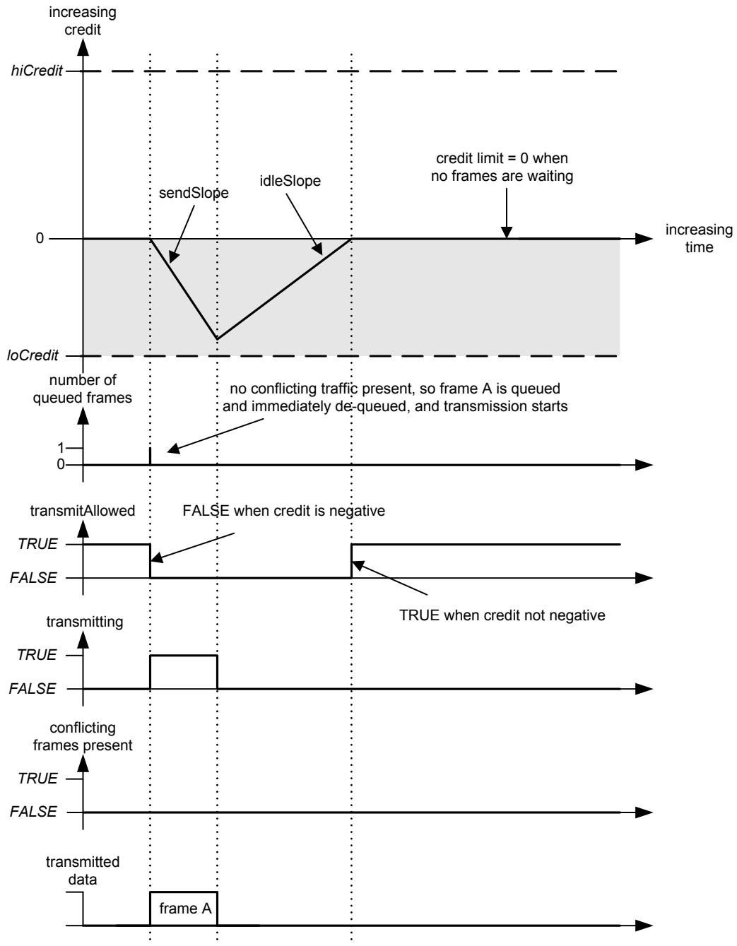
  Figure L-1—Credit-based shaper operation—no conflicting traffic


  If a continuous stream of frames is made available to the shaper algorithm, i.e., there is always one frame queued awaiting transmission when the credit value reaches zero, then the fraction of the portTransmitRate that is available to the queue (bandwidthFraction) is equal to the fraction of time that frames are being transmitted from the queue. Assuming that credit decreases to value loCredit at the end of each frame transmission, then the following shows the detailed derivation of Equation (L.1):

  $$
  \text { bandwidthFraction } = (- \text { loCredit / sendSlope }) / [ (- \text { loCredit / sendSlope }) + (\text { loCredit / idleSlope }) ] \tag {L.5}
  $$

  $$
  = (- 1 / \text { sendSlope }) / [ (1 / \text { idleSlope }) - (1 / \text { sendSlope }) ] \tag {L.6}
  $$

  $$
  = (- i d l e S l o p e) / (s e n d S l o p e - i d l e S l o p e) \tag {L.7}
  $$

  $$
  = \text { idleSlope } / \text { portTransmitRate } \tag {L.8}
  $$

  This fraction of the bandwidth is available to the stream even in the presence of conflicting traffic, as illustrated in the following examples. In Figure L-2, a frame is queued at a time when the Port is transmitting conflicting traffic. The value of credit increases at the rate of idleSlope while the queued frame waits for the Port to become available. Transmission of the conflicting traffic completes before the value of credit is limited by hiCredit, and transmission of the queued frame starts. The value of credit starts to decrease at the rate of sendSlope; however, as the frame is not large enough to consume all of the available credit, and there are no further frames queued, credit is reduced to zero on completion of the transmission.

![image](https://cdn-mineru.openxlab.org.cn/result/2026-05-27/878f926e-6587-4767-a01e-239a74a4d897/3af43710f4932ef1ba9babac1d38a80e416ac27f83fa17962761094e9804746e.jpg)


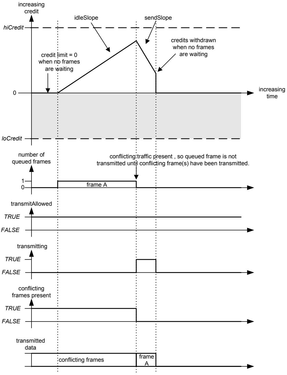
  Figure L-2—Credit-based shaper operation–conflicting traffic


  In Figure L-3, three frames are queued while the Port is transmitting conflicting traffic, and credit accumulates at the rate of idleSlope. Once the conflicting traffic has been transmitted, the first and second frames are transmitted back-to-back, because transmitting the first frame leaves credit ≥ 0. However, as transmitting the second frame causes credit to become negative, transmission of the third frame is delayed until credit returns to zero.

![image](https://cdn-mineru.openxlab.org.cn/result/2026-05-27/878f926e-6587-4767-a01e-239a74a4d897/ef891d1dc51a1cf80192e5974792c611f4b6b260aca796a2ba72dc93113f8c19.jpg)


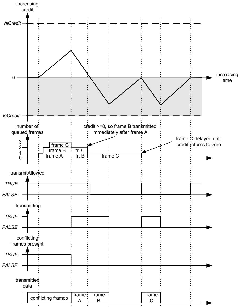
  Figure L-3—Credit-based shaper operation—burst traffic


# L.2 “Class measurement intervals” in Bridges

  The “class measurement interval” defines acceptable Talker behavior with respect to per-stream transmission (see 34.6.1); however, it does not directly impact the operation of the credit-based shaper algorithm in Bridges.

  The maximum fraction of the available bandwidth that a queue operating the credit-based shaper algorithm consumes is determined by idleSlope, as discussed in L.1; if idleSlope is 75% of the link transmission rate, then the algorithm gets a maximum of 75% of the link, averaged over some time period (the class measurement interval) at the Talker. For a Bridge, where transmission becomes bursty due to interfering transmission from other traffic classes, the minimum measurement interval that is meaningful (i.e., the minimum period over which it is still possible to observe that the 75% maximum bandwidth is not exceeded) is the time taken for the traffic class concerned to transmit a maximum sized burst, multiplied by 100/75. In the case of the 125 microsecond class measurement interval for SR class A traffic, on 100 Mbit/s Ethernet, and with 75% reservation, the approximate calculation is (ignoring interframe gaps):

  a) The maximum interference size (maxInterferenceSize) is one maximum sized Ethernet frame, which is 2000 octets, or 16000 bits, so hiCredit would be 75% of that, or 12000 bits.

  NOTE 1—Media access delays, such as those imposed by Energy Efficient Ethernet, could be more significant than the interference created by a maximum sized frame.

  NOTE 2—The figure of 2000 octets is a maximum for Ethernet and therefore a worst case for an interfering frame; in a specific implementation, the maximum frame size that is used could be smaller. In implementations where the maximum frame size is known to be less than 2000, the smaller value could be used.

  b) The maximum frame size for this traffic class is 75% of the number of bits that can be transmitted in 125 µs, so 75% of 12 500 bits in the case of a 100 Mbit/s LAN, or 9375 bits (including up to 500 or so possible “overhead” octets—used for Tag headers, physical layer overhead, etc.). As this is not an integral number of octets, this figure is rounded down to 9368. loCredit is 25% of that, or –2342.

  c) The maximum burst size, for frames no greater than 9368 bits long, would occur if credit reached 1200, then a series of frames were transmitted that exactly took credit to 0, followed by a final 9368 bit frame that would take credit down to –2342. This maximum burst is therefore calculated as: (12 000 + 2342) • (portTransmitRate/(-sendSlope)) or 57 368 bits.

  d) The minimum measurement interval over which one can expect to be able to measure the bandwidth utilisation for SR class A, and observe that it does not exceed its 75% allocation, is therefore 57368 bit times multiplied by 100/75, which is 76 491 bit times, rounded up to the nearest integer, or 764.91 µs.

  NOTE 3—The maximum sized burst will be preceded by a maxInterferenceSize event, and at the end of the burst, credit will have been reduced to –2342; it will therefore take 2342/idleSlope seconds, or nearly 3123 bit times, for credit to return to zero, and for SR Class A to be allowed to transmit again. In addition, the actual utilization for SR Class A is 57368/(57368+16000+ (2342/0.75)) = 75%.

  For the SR class B traffic, all that really changes is the potential size of any interference, which increases from the SR class A maxInterferenceSize to the maximum burst size for SR class A plus the class A maxInterferenceSize.

  So, the smallest possible measurement interval over which the ratio idleSlope/portTransmitRate will be seen to hold good is dependent on the maximum interference size for the SR class, the maximum frame size for the SR class, and the value of idleSlope.

# L.3 Determining worst-case latency contribution and buffering requirements

  From the point of view of the operation of AV Bridges, it is important to be able to assess the contribution that each bridge makes to the worst case latency that stream data frames can be subject to during their transmission along the path from Talker to Listener. Closely related to the latency contribution that a Bridge makes is the buffering requirement that is required in the Bridge in order for the delay not to result in frame discard; if a Bridge can potentially delay a frame of a given SR class for a given period of time, then it must be capable of buffering the worst-case number of frames of that same SR class that could be received for onward transmission on each Port. The following discussion looks at the factors that contribute to the delay that could be experienced by a frame as it passes through a Bridge, and how the delay can be accurately determined.

  NOTE 1—This discussion is also useful to guide designers of Talker stations in determining the delay added by the Talker’s network interface.

  The worst case latency for a single hop from Bridge to Bridge, measured from arrival of the last bit at Port n of Bridge A to the arrival of the last bit at Port m of Bridge B, can be broken out into the following components:

  a) Input queuing delay. (There are no input queues in the IEEE 802.1 architecture, but if present, the implementation must account for them.)

  b) Interference delay (L.3.1).

  c) Frame transmission delay. (The time taken to transmit one maximum frame at portTransmitRate.)

  d) LAN propagation delay. (A variable delay that depends on the length of the LAN connection to the next Bridge; this is measurable using the mechanisms defined in IEEE P802.1ASTM 5 [B30].)

  e) Store-and-forward delay. This includes all other elements of forwarding delay that are a consequence of the internal processing of the Bridge, assuming that the input and output queues are empty, such as:

    1) The time needed to pass a frame from the input port to the output port, assuming empty queues.

    2) The time delay between a frame being available for transmission on a Port and the Port being ready to transmit the frame.

  NOTE 2—For example, in the case where the MAC/PHY has entered a power saving mode, there may be a delay incurred in switching the Port back to normal operation.

    3) The difference, if any, in the delay incurred by a frame that bypasses an empty queue, vs. that incurred by a frame that must be enqueued.

    4) The time added (subtracted) by the lengthening (shortening) of the frame due to addition (removal) of frame headers such as Q-tags or MACSec-tags.

    5) The time needed to encrypt a MACSec frame.

  In the remainder of this clause, the following abbreviations are used:

<table><tr><td><eq>M_0</eq></td><td>Maximum sized frame for non-SR classes</td></tr><tr><td><eq>M_x</eq></td><td>Maximum sized frame for SR class x</td></tr><tr><td><eq>R_0</eq></td><td>portTransmitRate</td></tr><tr><td><eq>R_x</eq></td><td>idleSlope for SR class x</td></tr><tr><td><eq>T_{xy}</eq></td><td>Time interval between events x and y</td></tr><tr><td><eq>W_x</eq></td><td>-sendSlope<eq>_x</eq></td></tr><tr><td>variable<eq>_{&lt;x}</eq></td><td>The sum of the values of the named variable for all SR classes with a higher priority (and therefore earlier letter in the collating sequence) than x</td></tr></table>

# L.3.1 Interference delay

  The interference delay for frame X can be broken out into the following components:

  a) Queuing delay: The delay caused by the frame that was selected for transmission an arbitrarily small time before frame X became eligible for transmission selection, plus the delay caused by queued-up frames from all stream frames with higher priority than frame X’s class (i.e., the “maxBurstSize” for SR Classes with higher priority than X—see L.1). This is what is referred to as maxInterferenceSize in L.1. Queuing delay is analyzed in detail in L.3.1.1.

  b) Fan-in delay: The delay caused by other frames in the same class as frame X that arrive at more-orless the same time from different input Ports. Fan-in delay is analyzed in detail in L.3.1.2.

  c) Permanent delay: The delay caused by frames that reside in a buffer for a long time, relative to the output queuing delay, because of the history of activity in the network. Permanent delay is analyzed in detail in L.3.1.3.

# L.3.1.1 Queuing delay

  The queuing delay for frame X can be broken out into the following components:

  a) The delay, maxInterferenceTime, before a frame X queued for an SR class, and that is eligible for transmission, can actually be transmitted. This delay is experienced when a frame, of any priority, is selected for transmission an arbitrarily small time before frame X became eligible for transmission; it is also experienced in LAN media, such as Ethernet, where there can be a low energy consumption mode that is entered under idle conditions, and where there is a significant delay, mediumAccessDelay, before the LAN returns to normal operation and is able to transmit. The value of maxInterferenceTime is therefore equal to whichever is the greater of the following:

    1) The time taken to transmit the maximum frame size supported by the medium, i.e., max $F r a m e S i z e _ { ( m ) } /$ portTransmitRate.

    2) The mediumAccessDelay for the medium.

  b) The delay caused by any queued-up frames associated with the next higher priority SR class than frame X’s SR class (i.e., maxBurstSize for the next higher priority SR class), if frame X does not belong to the highest SR class.

  For SR class A, only the first of these components applies, as there is no higher SR class.

  Suppose that the queue for SR class A is full, and it has accumulated the maximum amount of credit (hiCredit). Because SR class A frames have priority over all other traffic (even BPDUs), hiCredit for SR class A is merely the credit accumulated during the maxInterferenceTime required to transmit a lowerpriority frame. Until that accumulated credit is exhausted, SR class B (C, D,...) frames cannot be transmitted.

  If SR class A were permitted to use 100% of the LAN bandwidth, then the SR class A queue would never catch up, because it would use credit as fast as it was gained, and there would never be a chance for any other traffic class to transmit a frame. If SR class A were permitted to use 99% of the LAN bandwidth, then SR class A can transmit back-to-back frames and the accumulated credit would be drained at 1% of the LAN bandwidth until it goes negative; at that point, SR class A cannot transmit further frames until its credit returns to a non-negative value, which ensures that at least 1% of the bandwidth is available to other traffic classes.

  NOTE—In general, if SR Class A is permitted to use X% of the bandwidth, then only (100-X)% remains available for use by lower priority traffic classes. In practice, as 75% is the default value for the highest percentage of portTransmitRate that can be used by all SR classes, there is always at least 25% of portTransmitRate available for use by the non-SR traffic classes.

  Figure L-4 illustrates this burst transmission behavior, and the effect of maxInterferenceTime on the latency of SR class frames. At point a on the time line, the queues for SR classes A and B are empty, and a maximum sized frame $( \mathrm { M } _ { 0 }$ bits long) belonging to a non-SR traffic class starts transmission. An instant later, SR class A and B frames arrive that are all of the maximum size that the classes are currently experiencing $( \mathrm { { M } _ { A } }$ and $\mathrm { { { M } _ { B } } }$ bits long respectively); however, as there is a frame already being transmitted, they are queued. At point b, transmission of the non-SR class frame completes, and the first of a burst of four SR class A frames are transmitted. By point d, SR class A’s credit has been taken negative by the transmission of the last of its burst of frames, and therefore no further SR Class A frames can be transmitted until its credit is no longer negative; this allows SR Class B to transmit a frame. What happens at the end of the class B frame will depend on what frames are queued waiting for transmission, and whether the credit available to either of the SR classes is non-negative.

![image](https://cdn-mineru.openxlab.org.cn/result/2026-05-27/878f926e-6587-4767-a01e-239a74a4d897/62a977ef90b0ff0b1bbf1903df2c1a57857c52471e8bfb6e06848b5dd0cec2c3.jpg)


  Figure L-4—Interference and latency


  The queuing delay experienced by the first SR Class A frame is therefore the time interval between a and $b ,$ $\mathrm { T _ { a b } } .$ If $\mathrm { R } _ { 0 }$ is the transmission rate (portTransmitRate), then:

  $$
  \mathrm{T} _ {\mathrm{ab}} = \mathrm{M} _ {0} / \mathrm{R} _ {0} = \text { max   InterferenceTime } \tag {L.9}
  $$

  Figure L-5 shows how credit changes for SR Class A during this sequence.

![image](https://cdn-mineru.openxlab.org.cn/result/2026-05-27/878f926e-6587-4767-a01e-239a74a4d897/19fe1cf520418379b4a2947ef5a85670164866db0c747774faf5a4a8d8034842.jpg)


  Figure L-5—Burst behavior and credit


  $\mathrm { R _ { A } }$ is the reserved data rate for SR Class A (which is the idleSlope for class A), $\mathrm { R _ { B } }$ is the reserved data rate for SR Class B, and so on. The value of $c r e d i t _ { \mathrm { A } }$ accumulates up to $h i C r e d i t _ { \mathrm { A } }$ during the transmission of the maximum sized non-SR frame, so:

  $$
  h i C r e d i t _ {\mathrm{A}} = \mathrm{R} _ {\mathrm{A}} \times \mathrm{M} _ {0} / \mathrm{R} _ {0} = \text { idleSlope } _ {\mathrm{A}} \times \text { maxInterferenceTime } \tag {L.10}
  $$

  credit is drained during the transmission of the SR Class A frames, at the rate sendSlope $\mathrm { ^ { \circ } A ^ { \mathrm { i } } }$ :

  $$
  \text { sendSlope } _ {\mathrm{A}} = \left(\mathrm{R} _ {\mathrm{A}} - \mathrm{R} _ {0}\right) \tag {L.11}
  $$

  credit reaches zero at point c in Figure L-5, which, for the purposes of this discussion, is assumed to happen exactly at the point where transmission of the third class A frame finishes. Since a frame can be transmitted when credit = 0, Class A’s credits continue to drain to the value:

  $$
  \text { loCredit } _ {A} = \left(\mathrm{R} _ {\mathrm{A}} - \mathrm{R} _ {0}\right) \times \mathrm{M} _ {\mathrm{A}} / \mathrm{R} _ {0} \tag {L.12}
  $$

  during the transmission of the fourth class A frame $( \mathrm { { M } _ { A } }$ bits long, transmitted in time $\mathrm { M _ { A } / R _ { 0 } } )$ . At point d, transmission of the fourth frame completes; as $c r e d i t _ { A }$ is now negative, no more class A frames can be transmitted, and transmission of a class B frame starts.

  So, for class A, the maximum burst size is equal to the transmission rate, $\mathrm { R } _ { 0 } .$ , multiplied by the time interval between points b and d in Figure L-5:

  $$
  \max \text { Class   A   burst   size } = R _ {0} \times (- (h i C r e d i t _ {A} - l o C r e d i t _ {A}) / s e n d S l o p e _ {A}) \tag {L.13}
  $$

  Substituting $h i C r e d i t _ { A } ,$ sendSlopeA, and $l o C r e d i t _ { A }$ from Equation (L.10), Equation (L.11), and Equation (L.12) respectively:

  $$
  \max \text { Class   A   burst   size } = R _ {0} \times \left(- \left(R _ {\mathrm{A}} \times M _ {0} / R _ {0} - \left(R _ {\mathrm{A}} - R _ {0}\right) \times M _ {\mathrm{A}} / R _ {0}\right) / \left(R _ {\mathrm{A}} - R _ {0}\right)\right) \tag {L.14}
  $$

  $$
  = \mathrm{R} _ {0} \times \left(\mathrm{R} _ {\mathrm{A}} \times \mathrm{M} _ {0} / \mathrm{R} _ {0}\right) / \left(\mathrm{R} _ {0} - \mathrm{R} _ {\mathrm{A}}\right) + \mathrm{M} _ {\mathrm{A}} / \mathrm{R} _ {0} \tag {L.15}
  $$

  $$
  = \left(\mathrm{R} _ {\mathrm{A}} \times \mathrm{M} _ {0}\right) / \left(\mathrm{R} _ {0} - \mathrm{R} _ {\mathrm{A}}\right) + \mathrm{M} _ {\mathrm{A}} \tag {L.16}
  $$

  The queuing delay experienced by SR class B is the time interval between a and d in Figure L-5, $\mathrm { T _ { a d } } \mathrm { : }$

  $$
  \mathrm{T} _ {\mathrm{ad}} = \mathrm{T} _ {\mathrm{ab}} + \mathrm{T} _ {\mathrm{bc}} + \mathrm{T} _ {\mathrm{cd}} \tag {L.17}
  $$

  $$
  = \mathrm{M} _ {0} / \mathrm{R} _ {0} + h i C r e d i t _ {A} / s e n d S l o p e _ {A} + \mathrm{M} _ {\mathrm{A}} / \mathrm{R} _ {0} \tag {L.18}
  $$

  $$
  = \mathrm{M} _ {0} / \mathrm{R} _ {0} + \left(\mathrm{R} _ {\mathrm{A}} \times \mathrm{M} _ {0} / \mathrm{R} _ {0}\right) / \left(\mathrm{R} _ {0} - \mathrm{R} _ {\mathrm{A}}\right) + \mathrm{M} _ {\mathrm{A}} / \mathrm{R} _ {0} \tag {L.19}
  $$

  $$
  = \mathrm{M} _ {0} / \left(\mathrm{R} _ {0} - \mathrm{R} _ {\mathrm{A}}\right) + \mathrm{M} _ {\mathrm{A}} / \mathrm{R} _ {0} \tag {L.20}
  $$

  This can be generalized to calculate the queuing delay experienced by any SR class, X, by using the sum of the credits available to all higher priority SR classes. In the following, the subscript $^ { \infty } < \mathrm { X } ^ { \infty }$ is used to indicate the sum of the values for all SR classes with higher priority (and therefore, earlier letters in the collating sequence) than X.

  The credit acquisition rate $i d l e S l o p e _ { < X }$ for SR classes A through X-1 is the sum of the data rates for all higher priority classes, so:

  $$
  i d l e S l o p e _ {<   X} = \sum_ {\mathrm{K} <   \mathrm{X}} \mathrm{R} _ {\mathrm{K}} \tag {L.21}
  $$

  This is just the sum of the $i d l e S l o p e _ { K }$ values for the higher classes. However, the combined classes accumulate credits only until the single interfering non-SR interfering frame stops transmitting, and then the credits start decreasing linearly. So, the upper limit for the combined credits is not the sum of the individual Class’s credits; it is the number of bits divided by the slope, or:

  $$
  h i C r e d i t _ {<   X} = \left(\sum_ {K <   X} R _ {K}\right) \times M _ {0} / R _ {0} \tag {L.22}
  $$

  Similarly, the combined sendSlope<X is:

  $$
  \text { sendSlope } _ {<   X} = - \left(\mathrm{R} _ {0} - \sum_ {\mathrm{K} <   X} \mathrm{R} _ {\mathrm{K}}\right) \tag {L.23}
  $$

  These combined rates hold true until some class’s buffer empties and its credits are forced to 0. In the worstcase scenarios we are examining, this does not happen.

  Defining

  $$
  \mathrm{W} _ {<   \mathrm{X}} = - \text { sendSlope } _ {<   \mathrm{X}} = \mathrm{R} _ {0} - \sum_ {\mathrm{K} <   \mathrm{X}} \mathrm{R} _ {\mathrm{K}} \tag {L.24}
  $$

  we have:

  $$
  \text { sendSlope } _ {<   X} = - \mathrm{W} _ {<   X} \tag {L.25}
  $$

  and

  $$
  h i C r e d i t _ {<   X} = \left(\mathrm{R} _ {0} - \mathrm{W} _ {<   X}\right) \times \mathrm{M} _ {0} / \mathrm{R} _ {0} \tag {L.26}
  $$

  For all combined classes, $\mathrm { T _ { a b } }$ is the same as for SR class A, the time for the non-SR frame to transmit:

  $$
  \mathrm{T} _ {\mathrm{ab}} = \mathrm{M} _ {0} / \mathrm{R} _ {0} \tag {L.27}
  $$

  The combined classes A through X-1 drain from hiCredit<X to 0 in time hiCredit $_ { < X } / \mathrm { \Delta W _ { < X } }$ , so:

  $$
  \mathrm{T} _ {\mathrm{bc}} = \left(\left(\mathrm{R} _ {0} - \mathrm{W} _ {<   \mathrm{X}}\right) \times \mathrm{M} _ {0} / \mathrm{R} _ {0}\right) / \mathrm{W} _ {<   \mathrm{X}} \tag {L.28}
  $$

  The worst case value of $l o C r e d i t { _ { < X } }$ for the combined <X classes is not the sum $\scriptstyle \sum \ K < X$ loCreditK as this would overestimate the worst case. Only one of the <X classes can be transmitting a frame at a given time, so the end of the burst for the <X classes occurs when one of the ${ < } \mathrm { X }$ classes, Q say, starts transmitting a frame at a point where all the other <X classes have negative credit, and their credit is therefore rising. If, by the time $\mathrm { Q } \mathrm { \ ' } \mathrm { s }$ frame transmission finishes, the other <X classes still have negative credit, then Q’s frame is the last frame of the <X burst; but at that point, all the other <X classes must, by definition, have more credit than their respective loCredit values (i.e., for these other classes, credit > loCredit) because even if they were at their respective loCredit values when Q started transmitting, they have been gaining credit during the transmission of Q’s frame.

  It is also not possible to decide that $l o C r e d i t { _ { < X } }$ is simply the time needed to transmit one copy of each Class’s maximum-length frame; for some classes it could be possible transmit more than a single last frame after the total credits = 0, even if all Classes’ credits reach 0 simultaneously. For example, classes A and B reach credit = 0 at the same time; A transmits a frame, then B transmits a frame. By the end of the B frame, A’s credit has returned to zero, and so A can transmit a further “last” frame.

  Some class must transmit the last frame, and for it to be the worst case, that last frame is a maximum length frame. If it were not, then either:

  c) Extending it to the maximum length still leaves the other classes at negative credit; or

  d) Extending it to the maximum length leaves one or more other class with 0 or positive credit, in which case they will transmit more frames.

  So, for class Q to be the class that transmits the last frame of the <X burst, the following condition must be true for all other <X classes, P:

  $$
  \mathrm{M} _ {\mathrm{q}} \times \mathrm{R} _ {\mathrm{P}} > \left(\mathrm{R} _ {0} - \mathrm{R} _ {\mathrm{P}}\right) \times \mathrm{M} _ {\mathrm{p}} \tag {L.29}
  $$

  Equation (L.29) follows from the fact that the increase in credits of class P during the transmission of $\mathrm { { \cal M } } _ { \mathrm { q } } ,$ which is equal to $( \mathbf { M } _ { \mathrm { q } } / \mathbf { R } _ { 0 } ) \times \mathbf { R } _ { \mathrm { P } }$ is greater than the absolute value of the loCredit of P, which is equal to $( \mathrm { R } _ { 0 } \dot { - }$ $\mathrm { R } _ { \mathrm { P } } ) \times \mathrm { M } _ { \mathrm { p } }$ . So:

  $$
  \left(\mathrm{M} _ {\mathrm{q}} / \mathrm{R} _ {0}\right) \times \mathrm{R} _ {\mathrm{P}} > \left(\mathrm{R} _ {0} - \mathrm{R} _ {\mathrm{P}}\right) \times \mathrm{M} _ {\mathrm{p}} / \mathrm{R} _ {0} \tag {L.30}
  $$

  This statement is true because the other classes P must have low enough credit that their credit cannot climb above 0 during the transmission of $\mathbf { M } _ { \mathrm { q } } .$ .

  The very lowest that $c r e d i t _ { \mathrm { < X } }$ might reach for three SR classes, Q, P, and S is shown in Equation (L.31).

  $$
  \text { loCredit } _ {<   \mathrm{X}} \geq \text { loCredit } _ {\mathrm{Q}} + \text { loCredit } _ {\mathrm{P}} + \text { loCredit } _ {\mathrm{S}} + \mathrm{R} _ {\mathrm{S}} \times \mathrm{M} _ {\mathrm{q}} / \mathrm{R} _ {0} + \mathrm{R} _ {\mathrm{P}} \times \mathrm{M} _ {\mathrm{q}} / \mathrm{R} _ {0} \tag {L.31}
  $$

  However, even this is pessimistic, as it assumes that more than one class can be at their loCredit at the same time, which is not the case. What this shows, however, is that if $\mathrm { R } _ { \mathrm { K } }$ is small for all $\operatorname { K } { < } \operatorname { X } \left( \mathrm { i . e . , R _ { K } } { < } { < } \operatorname { R } _ { 0 } \right)$ , then the $\mathrm { R _ { K } } \times \mathrm { M _ { q } } / \mathrm { R _ { 0 } }$ terms all approach zero, and therefore, $l o C r e d i t { _ { < X } }$ approaches the sum $\Sigma _ { \mathrm { K } < \mathrm { X } } \bar { l o } C r e d i t _ { \mathrm { K } }$ . So:

  $$
  \text { loCredit } _ {<   \mathrm{X}} = \sum_ {\mathrm{K} <   \mathrm{X}} \text { loCredit } _ {\mathrm{K}} \tag {L.32}
  $$

  $$
  = \sum_ {\mathrm{K} <   \mathrm{X}} \left(\mathrm{R} _ {\mathrm{K}} - \mathrm{R} _ {0}\right) \times \mathrm{M} _ {\mathrm{K}} / \mathrm{R} _ {0} \tag {L.33}
  $$

  But in this worst case, $\mathrm { R } _ { \mathrm { K } } { < } < \mathrm { R } _ { 0 } ,$ , so:

  $$
  \text { loCredit } _ {<   \mathrm{X}} = \sum_ {\mathrm{K} <   \mathrm{X}} (- \mathrm{M} _ {\mathrm{K}}) \tag {L.34}
  $$

  Putting together these various components, the queuing delay for SR Class X, qDelayX, is as follows:

  $$
  \mathrm{qDelay} _ {\mathrm{X}} = \mathrm{M} _ {0} / \mathrm{R} _ {0} + (h i C r e d i t _ {<   \mathrm{X}} - l o C r e d i t _ {<   \mathrm{X}}) / | s e n d S l o p e _ {<   \mathrm{X}} | \tag {L.35}
  $$

  $$
  = \mathrm{M} _ {0} / \mathrm{R} _ {0} + \left(\left(\mathrm{R} _ {0} - \mathrm{W} _ {<   \mathrm{X}}\right) \times \mathrm{M} _ {0} / \mathrm{R} _ {0} + \sum_ {\mathrm{K} <   \mathrm{X}} \mathrm{M} _ {\mathrm{K}}\right) / \mathrm{W} _ {<   \mathrm{X}} \tag {L.36}
  $$

  $$
  \mathrm{qDelay} _ {\mathrm{X}} = \left(\mathrm{M} _ {0} + \sum_ {\mathrm{K} <   \mathrm{X}} \mathrm{M} _ {\mathrm{K}}\right) / \mathrm{W} _ {<   \mathrm{X}} \tag {L.37}
  $$

  For SR class A, this equation reduces to Equation (L.38):

  $$
  \mathrm{qDelay} _ {\mathrm{A}} = \mathrm{M} _ {0} / \mathrm{W} _ {<   \mathrm{A}} \tag {L.38}
  $$

  As there is not a $^ { \circ } < \mathsf { A } ^ { \circ }$ class, A being the highest priority class, $\mathrm { W _ { \mathrm { < A } } }$ is simply $\mathrm { R } _ { 0 } ,$ so this reduces to Equation (L.39):

  $$
  \mathrm{qDelay} _ {\mathrm{A}} = \mathrm{M} _ {0} / \mathrm{R} _ {0} \tag {L.39}
  $$

  This agrees with the earlier discussion in L.1.

  For SR class B, the equation reduces to Equation (L.40):

  $$
  \mathrm{qDelay} _ {\mathrm{B}} = \left(\mathrm{M} _ {0} + \mathrm{M} _ {\mathrm{A}}\right) / \mathrm{W} _ {\mathrm{A}} \tag {L.40}
  $$

  As $\mathrm { w _ { A } }$ is $- s e n d S l o p e _ { A } .$ , which is just $\mathrm { R } _ { 0 } - \mathrm { R } _ { \mathrm { A } }$ this can be rewritten as shown in Equation (L.41):

  $$
  \mathbf {q} \text {Delay} _ {\mathrm{B}} = \left(\mathbf {M} _ {0} + \mathbf {M} _ {\mathrm{A}}\right) / \left(\mathbf {R} _ {0} - \mathbf {R} _ {\mathrm{A}}\right) \tag {L.41}
  $$

  The maximum burst size for a given class, X, is the number of bits that can be transmitted in “back-to-back” frames by class X. The maximum burst occurs when that class has experienced the maximum queuing delay for that class, $\mathrm { \ q D e l a y _ { X } }$ , and class X is then able to transmit frames, uninterrupted by any higher priority classes, until it reaches loCreditX. The size of this burst, maxBurstX, is equal to the number of bits that can be transmitted at line rate, $\mathrm { R } _ { 0 } ,$ , in the time it takes for creditX to reduce from $h i C r e d i t _ { X }$ to $- l o C r e d i t _ { \mathrm { X } }$ , as follows in Equation (L.42):

  $$
  \max \text {Burst} _ {\mathbf {X}} = \left(h i C r e d i t _ {X} - l o C r e d i t _ {\mathrm{X}}\right) \times \mathrm{R} _ {0} / \mathrm{W} _ {\mathrm{X}} \tag {L.42}
  $$

  From the earlier results, the worst case for loCreditX is just $( - \mathbf { M } _ { \mathrm { X } } )$ , so:

  $$
  = h i C r e d i t _ {X} \times \mathrm{R} _ {0} / \mathrm{W} _ {\mathrm{X}} + \mathrm{M} _ {\mathrm{X}} \times \mathrm{R} _ {0} / \mathrm{W} _ {\mathrm{X}} \tag {L.43}
  $$

  and $h i C r e d i t _ { \mathrm { X } }$ is the amount of credit that can be accumulated during qDelayX seconds, which is qDelayX multiplied by the idle slope, $\mathrm { R } _ { \mathrm { X } } ,$ so:

  $$
  \max \text {Burst} _ {\mathrm{X}} = \left(\mathrm{M} _ {0} + \sum_ {\mathrm{K} <   \mathrm{X}} \mathrm{M} _ {\mathrm{K}}\right) \times \mathrm{R} _ {\mathrm{X}} \times \mathrm{R} _ {0} / \left(\mathrm{W} _ {<   \mathrm{X}} \times \mathrm{W} _ {\mathrm{X}}\right) + \mathrm{M} _ {\mathrm{X}} \times \mathrm{R} _ {0} / \mathrm{W} _ {\mathrm{X}} \tag {L.44}
  $$

# L.3.1.2 Fan-in delay

  The delay caused by other frames in the same class as frame X that arrive at more-or-less the same time from different input Ports. Consider the scenario in Figure L-6, where a Bridge has a number of Ports on which it receives frames for a given SR Class and the frames will be queued on a single outbound Port. Imagine that the “upstream” Bridge Ports feeding every reception Port of the Bridge all encounter a maximum interference event for Class X at the same time. The output Port will be starved of data. Then, once the interference events complete, the “upstream” Bridges start to transmit frames and the input Ports all receive a frame at the same moment; all received frames are delivered to the output queue.

![image](https://cdn-mineru.openxlab.org.cn/result/2026-05-27/878f926e-6587-4767-a01e-239a74a4d897/f6ecace40c93f0cac07455088e2769585e6764dc9d57bedecc21e3e50b386a10.jpg)


  Figure L-6—Fan-in scenario


  Assuming that all of the Ports of the Bridge support the same data rate, and the outbound queues of the upstream Bridges are all configured the same as the outbound queue of this Bridge, then the outbound Port would not be able to transmit frames from its queue at the desired, combined data rate of the incoming traffic, as this would require the outbound Port (in this example) to transmit at 20 times its reserved data rate, which would not be permitted by the Stream Reservation Protocol. It follows that whatever the reserved data rate is on the outbound Port, this must be the same as the sum of the reserved data rates being fed into the inbound Ports.

  By allocating the majority of the reserved bandwidth to one of the inbound Ports (shown in grey in Figure L-6) and a very small amount of bandwidth to all of the other inbound Ports, the amount of fan-in data that will be received can be maximized; the grey Port will receive maxBurstX bits of burst data, and all other Ports will receive a single frame of length $\mathrm { M } _ { \mathrm { X } } .$ Hence, the data that the outbound queue has to handle in this scenario is maxBurs $\mathrm { \Delta } _ { \mathrm { X } } + 1 2 \times \mathrm { M } _ { \mathrm { X } }$ bits of fan-in data.

  NOTE 1—The reason that this choice maximizes the fan-in data burst size is that regardless of how little bandwidth is allocated to the black Ports, they still get to burst a complete frame.

  The following is a procedure (not a formula) for determining the maximum amount of fan-in data for a given SR class and output port:

  a) Determine $B _ { O } ,$ the maximum possible bandwidth for class X on the output port.

  b) For each possible input port i, determine the maximum possible bandwidth $B _ { i }$ for Class X—it is assumed that this information is obtained by some means, e.g., via LLDP, from the transmitting Bridge that is the source of the frames received by i.

  c) For input port i, calculate maxBurstX,i using max $( B _ { O } , B _ { i } )$ for the bandwidth. (In the maxBurst formula, use $\mathrm { W } _ { \mathrm { X } } = \mathrm { R } _ { 0 } - \operatorname* { m a x } ( B _ { O } , B _ { i } ) . .$ )

  d) Add max(maxBurstX,i) to the total fan-in data.

  e) Set $B _ { O } = B _ { O } - B _ { i }$ and repeat from step c) until $B _ { O } = 0$ .

  f) For each remaining port, add $\mathrm { M } _ { \mathrm { X , i } }$ i to the total fan-in data.

  The fan-in delay is then equal to the time taken for the total fan-in burst data, computed as shown above, to be output at the line rate of the output port.

  NOTE 2—The definition of a measurement interval for stream traffic specifications implies a minimum frame transmission rate (8000 frames per second for class A’s 125 us measurement interval). At this frame transmission rate, the frames are smaller and, due to the overhead in small frames, fewer streams are possible (no more than 13 through a 100 Mb port). These constraints should be given due consideration when determining the value to be used for $\mathrm { M } _ { \mathrm { X } }$ and for determining the maximum number of ports contributing to fan-in delay.

  Example calculations of fan-in delay can be found in the paper “Calculating the Delay Added by Qav Stream Queue” [B29].

# L.3.1.3 Permanent delay

  Permanent delay reflects the fact that, if a path through the network is being used continuously at its full capacity for a particular SR class, interfering traffic can cause “permanent” buffer occupancy at the point of congestion. This is illustrated in Figure L-7 through Figure L-10 and the accompanying text.

  In Figure L-7 we have a Talker station, T, that has reserved the highest possible bandwidth, $\mathrm { R } _ { \mathrm { X } } ,$ , for an SR class X stream on the path through 3 Bridges to Listener L. For the purposes of the discussion, $\mathtt { R } _ { \mathrm { X } }$ is the maximum reservable data rate for class X on the outbound Ports of all three Bridges, and Talker T starts transmitting the stream, at the reserved data rate $\operatorname { R } _ { \mathrm { X } } .$ . Assuming that the LANs are short and there is no interfering traffic (i.e., the only traffic being handled is this particular stream), the buffer occupancy in each Bridge will approach zero, as frames can be transmitted onwards as soon as they are received.

![image](https://cdn-mineru.openxlab.org.cn/result/2026-05-27/878f926e-6587-4767-a01e-239a74a4d897/d7824a28b48785e83a95f7f85f54b0f464cf42c062748d5d68306573505bcab6.jpg)


  Figure L-7—Permanent delay scenario


  In Figure L-8, a second transmission, Q, generates the maximum possible interference to class X (i.e., class X’s next frame for transmission is delayed by qDelayX). Talker T’s class X queue fills, and its credit increases to $h i C r e d i t _ { \mathrm { X } }$ (shown on the figure as $\scriptstyle { \mathrm { C } } = { \mathrm { C } } _ { \mathrm { X } } )$ . Because T is no longer transmitting class X frames, the downstream Bridges are starved of frames to transmit, their buffers are empty, and their credit is zero (C = 0).

  In Figure L-9, the interfering traffic goes away, and T is able to transmit a maximum sized class X burst of frames at line rate; once the burst has finished, T reverts to transmitting the stream at the reserved rate $\operatorname { R } _ { \mathrm { X } } .$ As Bridge 1 has no credit, it will have to buffer most of the burst of frames, and as T is sending frames as fast as Bridge 1 can get rid of them, its buffer occupancy will remain at that level unless something else affects that steady state. Bridge 1 ends up with a credit value that hovers around the hiCredit level; the credit in the other Bridges will have credit of 0 or some value between 0 and loCredit as the Bridges receive and transmit frames.

![image](https://cdn-mineru.openxlab.org.cn/result/2026-05-27/878f926e-6587-4767-a01e-239a74a4d897/789b55520a088321f4465db6e6628a475296e20a4414376d167107133952616b.jpg)


  Figure L-8—Building up buffer occupancy—1


![image](https://cdn-mineru.openxlab.org.cn/result/2026-05-27/878f926e-6587-4767-a01e-239a74a4d897/db8d338189a3ecf99f859a456434e7731824067b851d918929131908e6187900.jpg)


  Figure L-9—Building up buffer occupancy—2


  If the interfering traffic, Q, starts up again, Talker T’s buffer occupancy will build up again; however, as Bridge 1 still has frames buffered, it can continue to transmit, and the downstream Bridges are not starved of frames, and Bridge 1’s buffer occupancy and credit returns to around 0. When the interference stops, T transmits a burst at line rate, as before, which simply restores Bridge 1’s queue to the state shown in Figure L-9.

  If a new interfering frame source, S, starts up that affects class X in Bridge 1, then Bridges 2 and 3 could again be starved of traffic, and the buffer occupancy and credit in Bridge 1 could increase temporarily to $2 \mathrm { C _ { X } }$ (see Figure L-10). When S stops transmitting, then Bridge 2 can create a line rate burst of traffic that will restore its buffer to the previous steady state (Figure L-9), but now Bridge 2 has a permanent buffer loading as shown in Figure L-10.

![image](https://cdn-mineru.openxlab.org.cn/result/2026-05-27/878f926e-6587-4767-a01e-239a74a4d897/0e0c1b30c973469c3bdcc9f45b6e90eaf67e090494004e99de125c36d584e1fd.jpg)


  Figure L-10—Building up buffer occupancy—3


  This can of course happen for other Bridges in the path, leading eventually to some level of permanent buffer occupancy in each Bridge. The problem does not get any worse from that point on, because no Bridge ever starves (i.e., no Bridge’s credit is set to zero because it runs out of frames to send); starvation is a requirement in order for permanent partial occupancy to be created.

  It may, therefore, be considered desirable for all Bridges to reserve a little bit more bandwidth than the actual total reserved by the Talkers, so that this “permanent” buffer build-up can drain away. However, this would not make the problem significantly better on the timescales of the output queuing delay, so it does not factor into those calculations, and, of course, this additional capacity would increase the queuing delay at each hop.

![image](https://cdn-mineru.openxlab.org.cn/result/2026-05-27/878f926e-6587-4767-a01e-239a74a4d897/42222f26918a3ddcf4317173277ec2b4d6934688e9d449d36241092e4db1dd76.jpg)


  Figure L-11—Building up buffer occupancy—4


  NOTE—Many applications have media clocks that are asynchronous to the free-running clock used to determine class measurement intervals. As the two clocks could be operating at the extremes of their permissible variation, it is necessary to reserve more bandwidth than is nominally needed in order to account for the potential difference in clock rate.

  Since this kind of event could happen on multiple input ports at the same time, the “permanently buffered” data equals the worst-case fan-in data.

# L.3.2 Maximum interference delay and maximum buffer requirement

  As discussed in L.3.1, the worst-case interference delay for SR class X on a given Port is the sum of the following three parts:

  a) qDelayX [see Equation (L.35) in L.3.1.1]

  b) The fan-in delay (see L.3.1.2)

  c) The “permanent” buffer contents contribution (see L.3.1.3), which is equal to the worst-case fan-in delay

  The buffering requirements for SR class X consist of the following three components:

  d) A contribution from the queuing delay, equal to maxBurstX

  e) The fan-in burst data size, computed as described in L.3.1.2

  f) The “permanent” buffer contents, which is equal to the fan-in burst data size.

  The fan-in burst size and the permanent buffer contents do not count twice; if a fan-in burst happens, then it becomes the permanent buffer contents. If it happens a second time, it can only happen after a pause that has allowed the permanent buffer loading to drain. So the worst case buffering requirement for SR class X is simply the sum of the first two elements, maxBurstX [Equation (L.42)] and fan-in burst data size, so:

  $$
  \max \text { Buffering } _ {\mathrm{X}} = \max \text { Burst } _ {\mathrm{X}} + (\text { fan - in   burst   data   size }) _ {\mathrm{X}} \tag {L.45}
  $$

  The worst-case total buffering requirement for all of the SR classes on a given Port is the sum of the following two parts:

  g) The worst-case buffering requirement for the lowest-priority SR class on that Port

  h) One max-size frame $\mathrm { M } _ { \mathrm { i } , Z }$ for each class Z of higher priority than Class X for each input port i.

  Since the worst case buffer requirement for Class X is when it is taking almost all of the bandwidth from the higher-priority classes, the SR priority levels can share buffering space. The only additional requirement is for the fan-in from higher priorities on other Ports. Thus, the SR classes would do well to share their buffer space on each Port.

# L.4 Operation of the credit-based shaper in a coordinated shared network

  A Coordinated Shared Network (CSN) is a contention free, QoS capable, time division multiplexed access, network. One of the nodes of the network acts as the Network Coordinator (NC) node granting transmission opportunities to the other nodes of the network. The NC node also acts as the QoS manager of the network.

  From the perspective of the specification of the credit-based shaper, a CSN is equivalent to a distributed bridge. Rather than shaping the AV traffic in the egress nodes, which could lack the buffering resources to do so, the shaping could instead be performed by the CSN’s Network Coordinator per Class of Service when it schedules transmissions opportunities from the CSN’s ingress to the CSN egress nodes. The behavior of CSN’s egress to another MAC technology should be consistent with the behavior specified in this standard, regardless of how the shaper is implemented.
