802.1Q-2014
<!-- merged from 802.1Q_2014_0001-0200.md -->
IEEE Standard for Local and metropolitan area networks—
Bridges and Bridged Networks
IEEE Computer Society
Sponsored by the
LAN/MAN Standards Committee
IEEE
3 Park Avenue
New York, NY 10016-5997
USA
IEEE Std 802.1Q™-2014
(Revision of
IEEE Std 802.1Q-2011)
IEEE Standard for
Local and metropolitan area networks—
Bridges and Bridged Networks
Sponsor
LAN/MAN Standards Committee
of the
IEEE Computer Society
Approved 3 November 2014
IEEE-SA Standards Board
Abstract: This standard specifies how the Media Access Control (MAC) Service is supported by Bridged Networks, the principles of operation of those networks, and the operation of MAC Bridges and VLAN Bridges, including management, protocols, and algorithms
Keywords: Bridged Network, IEEE 802.1Q™, LAN, local area network, MAC Bridge, metropolitan area networks, MSTP, Multiple Spanning Tree Protocol, Rapid Spanning Tree Protocol, RSTP, PBN, Provider Bridged Network, Shortest Path Bridging Protocol, SPB Protocol, Virtual Bridged Network, virtual LAN, VLAN Bridge
The Institute of Electrical and Electronics Engineers, Inc.
3 Park Avenue, New York, NY 10016-5997, USA
Copyright © 2014 by The Institute of Electrical and Electronics Engineers, Inc.
All rights reserved. Published 19 December 2014. Printed in the United States of America.
IEEE and 802 are registered trademarks in the U.S. Patent & Trademark Office, owned by The Institute of Electrical and Electronics Engineers, Incorporated.
<table><tr><td>PDF:</td><td>ISBN 978-0-7381-9433-2</td><td>STD20044</td></tr><tr><td>Print:</td><td>ISBN 978-0-7381-9434-9</td><td>STDPD20044</td></tr></table>
IEEE prohibits discrimination, harassment and bullying. For more information, visit http://www.ieee.org/web/aboutus/whatis/policies/p9-26.html. No part of this publication may be reproduced in any form, in an electronic retrieval system or otherwise, without the prior written permission of the publisher.
Important Notices and Disclaimers Concerning IEEE Standards Documents
IEEE documents are made available for use subject to important notices and legal disclaimers. These notices and disclaimers, or a reference to this page, appear in all standards and may be found under the heading “Important Notice” or “Important Notices and Disclaimers Concerning IEEE Standards Documents.”
Notice and Disclaimer of Liability Concerning the Use of IEEE Standards Documents
IEEE Standards documents (standards, recommended practices, and guides), both full-use and trial-use, are developed within IEEE Societies and the Standards Coordinating Committees of the IEEE Standards Association (“IEEE-SA”) Standards Board. IEEE (“the Institute”) develops its standards through a consensus development process, approved by the American National Standards Institute (“ANSI”), which brings together volunteers representing varied viewpoints and interests to achieve the final product. Volunteers are not necessarily members of the Institute and participate without compensation from IEEE. While IEEE administers the process and establishes rules to promote fairness in the consensus development process, IEEE does not independently evaluate, test, or verify the accuracy of any of the information or the soundness of any judgments contained in its standards.
IEEE does not warrant or represent the accuracy or content of the material contained in its standards, and expressly disclaims all warranties (express, implied and statutory) not included in this or any other document relating to the standard, including, but not limited to, the warranties of: merchantability; fitness for a particular purpose; non-infringement; and quality, accuracy, effectiveness, currency, or completeness of material. In addition, IEEE disclaims any and all conditions relating to: results; and workmanlike effort. IEEE standards documents are supplied “AS IS” and “WITH ALL FAULTS.”
Use of an IEEE standard is wholly voluntary. The existence of an IEEE standard does not imply that there are no other ways to produce, test, measure, purchase, market, or provide other goods and services related to the scope of the IEEE standard. Furthermore, the viewpoint expressed at the time a standard is approved and issued is subject to change brought about through developments in the state of the art and comments received from users of the standard.
In publishing and making its standards available, IEEE is not suggesting or rendering professional or other services for, or on behalf of, any person or entity nor is IEEE undertaking to perform any duty owed by any other person or entity to another. Any person utilizing any IEEE Standards document, should rely upon his or her own independent judgment in the exercise of reasonable care in any given circumstances or, as appropriate, seek the advice of a competent professional in determining the appropriateness of a given IEEE standard.
IN NO EVENT SHALL IEEE BE LIABLE FOR ANY DIRECT, INDIRECT, INCIDENTAL, SPECIAL, EXEMPLARY, OR CONSEQUENTIAL DAMAGES (INCLUDING, BUT NOT LIMITED TO: PROCUREMENT OF SUBSTITUTE GOODS OR SERVICES; LOSS OF USE, DATA, OR PROFITS; OR BUSINESS INTERRUPTION) HOWEVER CAUSED AND ON ANY THEORY OF LIABILITY, WHETHER IN CONTRACT, STRICT LIABILITY, OR TORT (INCLUDING NEGLIGENCE OR OTHERWISE) ARISING IN ANY WAY OUT OF THE PUBLICATION, USE OF, OR RELIANCE UPON ANY STANDARD, EVEN IF ADVISED OF THE POSSIBILITY OF SUCH DAMAGE AND REGARDLESS OF WHETHER SUCH DAMAGE WAS FORESEEABLE.
Translations
The IEEE consensus development process involves the review of documents in English only. In the event that an IEEE standard is translated, only the English version published by IEEE should be considered the approved IEEE standard.
Official statements
A statement, written or oral, that is not processed in accordance with the IEEE-SA Standards Board Operations Manual shall not be considered or inferred to be the official position of IEEE or any of its committees and shall not be considered to be, or be relied on as, a formal position of IEEE. At lectures, symposia, seminars, or educational courses, an individual presenting information on IEEE standards shall make it clear that his or her views should be considered the personal views of that individual rather than the formal position of IEEE.
Comments on standards
Comments for revision of IEEE Standards documents are welcome from any interested party, regardless of membership affiliation with IEEE. However, IEEE does not provide consulting information or advice pertaining to IEEE Standards documents. Suggestions for changes in documents should be in the form of a proposed change of text, together with appropriate supporting comments. Since IEEE standards represent a consensus of concerned interests, it is important that any responses to comments and questions also receive the concurrence of a balance of interests. For this reason, IEEE and the members of its societies and Standards Coordinating Committees are not able to provide an instant response to comments or questions except in those cases where the matter has previously been addressed. For the same reason, IEEE does not respond to interpretation requests. Any person who would like to participate in revisions to an IEEE standard is welcome to join the relevant IEEE working group.
Comments on standards should be submitted to the following address:
Secretary, IEEE-SA Standards Board
445 Hoes Lane
Piscataway, NJ 08854 USA
Laws and regulations
Users of IEEE Standards documents should consult all applicable laws and regulations. Compliance with the provisions of any IEEE Standards document does not imply compliance to any applicable regulatory requirements. Implementers of the standard are responsible for observing or referring to the applicable regulatory requirements. IEEE does not, by the publication of its standards, intend to urge action that is not in compliance with applicable laws, and these documents may not be construed as doing so.
Copyrights
IEEE draft and approved standards are copyrighted by IEEE under U.S. and international copyright laws. They are made available by IEEE and are adopted for a wide variety of both public and private uses. These include both use, by reference, in laws and regulations, and use in private self-regulation, standardization, and the promotion of engineering practices and methods. By making these documents available for use and adoption by public authorities and private users, IEEE does not waive any rights in copyright to the documents.
Photocopies
Subject to payment of the appropriate fee, IEEE will grant users a limited, non-exclusive license to photocopy portions of any individual standard for company or organizational internal use or individual, non-commercial use only. To arrange for payment of licensing fees, please contact Copyright Clearance Center, Customer Service, 222 Rosewood Drive, Danvers, MA 01923 USA; +1 978 750 8400. Permission to photocopy portions of any individual standard for educational classroom use can also be obtained through the Copyright Clearance Center.
Updating of IEEE Standards documents
Users of IEEE Standards documents should be aware that these documents may be superseded at any time by the issuance of new editions or may be amended from time to time through the issuance of amendments, corrigenda, or errata. An official IEEE document at any point in time consists of the current edition of the document together with any amendments, corrigenda, or errata then in effect.
Every IEEE standard is subjected to review at least every ten years. When a document is more than ten years old and has not undergone a revision process, it is reasonable to conclude that its contents, although still of some value, do not wholly reflect the present state of the art. Users are cautioned to check to determine that they have the latest edition of any IEEE standard.
In order to determine whether a given document is the current edition and whether it has been amended through the issuance of amendments, corrigenda, or errata, visit the IEEE-SA Website at http://ieeexplore.ieee.org/xpl/standards.jsp or contact IEEE at the address listed previously. For more information about the IEEE-SA or IEEE's standards development process, visit the IEEE-SA Website at http://standards.ieee.org.
Errata
Errata, if any, for all IEEE standards can be accessed on the IEEE-SA Website at the following URL: http://standards.ieee.org/findstds/errata/index.html. Users are encouraged to check this URL for errata periodically.
Patents
Attention is called to the possibility that implementation of this standard may require use of subject matter covered by patent rights. By publication of this standard, no position is taken by the IEEE with respect to the existence or validity of any patent rights in connection therewith. If a patent holder or patent applicant has filed a statement of assurance via an Accepted Letter of Assurance, then the statement is listed on the IEEE-SA Website at http://standards.ieee.org/about/sasb/patcom/patents.html. Letters of Assurance may indicate whether the Submitter is willing or unwilling to grant licenses under patent rights without compensation or under reasonable rates, with reasonable terms and conditions that are demonstrably free of any unfair discrimination to applicants desiring to obtain such licenses.
Essential Patent Claims may exist for which a Letter of Assurance has not been received. The IEEE is not responsible for identifying Essential Patent Claims for which a license may be required, for conducting inquiries into the legal validity or scope of Patents Claims, or determining whether any licensing terms or conditions provided in connection with submission of a Letter of Assurance, if any, or in any licensing agreements are reasonable or non-discriminatory. Users of this standard are expressly advised that determination of the validity of any patent rights, and the risk of infringement of such rights, is entirely their own responsibility. Further information may be obtained from the IEEE Standards Association.
Participants
At the time this standard was submitted to the IEEE-SA Standards Board for approval, the IEEE 802.1 Working Group had the following membership:
Glenn Parsons, Chair
John Messenger, Vice Chair
Tony Jeffree, Editor
Stephen Haddock, Chair, Interworking Task Group
Ting Ao
Christian Boiger
Paul Bottorff
David Chen
Feng Chen
Weiying Cheng
Diego Crupnicoff
Rodney Cummings
Patrick Diamond
Aboubacar Kader Diarra
Janos Farkas
Norman Finn
Geoffrey Garner
Anoop Ghanwani
Mark Gravel
Eric W. Gray
Craig Gunther
Hitoshi Hayakawa
Jeremy Hitt
Rahil Hussain
Michael Johas Teener
Peter Jones
Hal Keen
Marcel Kiessling
Yongbum Kim
Philippe Klein
Jouni Korhonen
Jeff Lynch
Ben Mack-Crane
Christophe Mangin
James McIntosh
Eric Multanen
Donald Pannell
Karen Randall
Maximilian Riegel
Dan Romascanu
Jessy V. Rouyer
Panagiotis Saltsidis
Behcet Sarikaya
Michael Seaman
Daniel Sexton
Johannes Specht
Kevin B. Stanton
Wilfried Steiner
Vahid Tabatabaee
Patricia Thaler
Jeremy Touve
Karl Weber
Yuehua Wei
Brian Weis
Jordon Woods
Juan-Carlos Zuniga
The following members of the individual balloting committee voted on this standard. Balloters may have voted for approval, disapproval, or abstention.
Thomas Alexander
Butch Anton
Hugh Barrass
Christian Boiger
William Byrd
Juan Carreon
Keith Chow
Charles Cook
Rodney Cummings
Darold Davis
Sourav Dutta
Donald Eastlake
Richard Edgar
Donald Fedyk
Yukihiro Fujimoto
Randall Groves
Robert Grow
Craig Gunther
Chris Guy
Marek Hajduczenia
Werner Hoelzl
Rahil Hussain
Noriyuki Ikeuchi
Atsushi Ito
Tony Jeffree
Michael Johas Teener
Peter Jones
Shinkyo Kaku
Piotr Karocki
Stuart Kerry
Jeff Koftinoff
Bruce Kraemer
Hyeong Ho Lee
John Lemon
Elvis Maculuba
Roger Marks
Jeffery Masters
Jonathon Mclendon
John Messenger
Jose Morales
Michael Newman
Nick S. A. Nikjoo
Satoshi Obara
David Olsen
Glenn Parsons
Jean Pierre Picard
Maximilian Riegel
Robert Robinson
Benjamin Rolfe
Dan Romascanu
Jessy Rouyer
John Santhoff
Peter Saunderson
Bartien Sayogo
Michael Seaman
Shusaku Shimada
Kapil Sood
Kevin Stanton
Thomas Starai
Rene Struik
Walter Struppler
Joseph Tardo
William Taylor
Patricia Thaler
Dmitri Varsanofiev
Prabodh Varshney
Hung-Yu Wei
Andreas Wolf
Michael Wright
Oren Yuen
Daidi Zhong
Zhen Zhou
When the IEEE-SA Standards Board approved this standard on 3 November 2014, it had the following membership:
John Kulick, Chair
Jon Walter Rosdahl, Vice-chair
Richard H. Hulett, Past Chair
Konstantinos Karachalios, Secretary
Peter Balma
Farooq Bari
Ted Burse
Clint Chaplain
Stephen Dukes
Jean-Phillippe Faure
Gary Hoffman
Michael Janezic
Jeffrey Katz
Joseph L. Koepfinger*
David Law
Hung Ling
Oleg Logvinov
T. W. Olsen
Glenn Parsons
Ron Peterson
Adrian Stephens
Peter Sutherland
Yatin Trivedi
Phil Winston
Don Wright
Yu Yuan
*Member Emeritus
Also included are the following nonvoting IEEE-SA Standards Board liaisons:
Richard DeBlasio, DOE Representative
Michael Janezic, NIST Representative
Michelle Turner
IEEE-SA Content Publishing
Kathryn M. Bennett
IEEE-SA Standards Technical Community
Historical participants
Since the initial publication, many IEEE standards have added functionality or provided updates to material included in this standard. The following is a historical list of participants who have dedicated their valuable time, energy, and knowledge to the creation of this material:
<table><tr><td>IEEE 802.1Q Standard</td><td>Date approved by IEEE</td><td>Officers at the time of Working Group Letter Ballot</td></tr><tr><td>IEEE Std 802.1Q-1998</td><td>8 December 1998</td><td>William P. Lidinsky, ChairMick Seaman, Chair, Interworking Task GroupTony Jeffree, Coordinating EditorAnil Rijsinghani, Richard Hausmann, Michele Wright, Paul Langille, P. J. Singh, Editorial Team</td></tr><tr><td>IEEE Std 802.1u-2001</td><td>17 March 2001</td><td>Tony Jeffree, ChairNeil Jarvis, Vice ChairMick Seaman, Chair, Interworking Task Group</td></tr><tr><td>IEEE Std 802.1v-2001</td><td>17 March 2001</td><td>Tony Jeffree, ChairNeil Jarvis, Vice ChairMick Seaman, Chair, Interworking Task GroupDavid Delany, EditorAndrew Smith, Editor</td></tr><tr><td>IEEE Std 802.1s-2002</td><td>11 December 2002</td><td>Tony Jeffree, ChairNeil Jarvis, Vice ChairMick Seaman, Chair, Interworking Task GroupNorman W. Finn, Editor</td></tr><tr><td>IEEE Std 802.1ad-2005</td><td>28 March 2005</td><td>Tony Jeffree, ChairPaul Congdon, Vice ChairMick Seaman, Chair, Interworking Task GroupStephen R. Haddock, Editor</td></tr><tr><td>IEEE Std 802.1Q-2005</td><td>7 December 2005</td><td>Tony Jeffree, Chair and EditorPaul Congdon, Vice ChairMick Seaman, Chair, Interworking Task Group</td></tr><tr><td>IEEE Std 802.1ak-2007</td><td>22 March 2007</td><td>Tony Jeffree, Chair and EditorPaul Congdon, Vice ChairMick Seaman, Chair, Interworking Task Group</td></tr><tr><td>IEEE Std 802.1ag-2007</td><td>27 September 2007</td><td>Tony Jeffree, ChairPaul Congdon, Vice ChairStephen R. Haddock, Chair, Interworking Task GroupNorman W. Finn, Editor-in-ChiefDavid V. Elie-Dit-Cosaque, Dinesh Mohan, Oscar Rodriguez, and Ali Sajassi, Assistant Editors</td></tr><tr><td>IEEE Std 802.1ah-2008</td><td>12 June 2008</td><td>Tony Jeffree, ChairPaul Congdon, Vice ChairStephen R. Haddock, Chair, Interworking Task GroupPaul Bottorff, Stephen Haddock, and Muneyoshi Suzuki, Editors</td></tr><tr><td>IEEE Std 802.1Q-2005/ Cor-1-2008</td><td>26 September 2008</td><td>Tony Jeffree, Chair and EditorPaul Congdon, Vice ChairStephen R. Haddock, Chair, Interworking Task Group</td></tr><tr><td>IEEE Std 802.1ap-2008</td><td>10 December 2008</td><td>Tony Jeffree, ChairPaul Congdon, Vice ChairStephen R. Haddock, Chair, Interworking Task GroupGlenn Parsons, EditorDavid Levi, Assistant Editor</td></tr><tr><td>IEEE Std 802.1Qaw-2009</td><td>17 June2009</td><td>Tony Jeffree, ChairPaul Congdon, Vice ChairStephen R. Haddock, Chair, Interworking Task GroupLinda Dunbar, Editor</td></tr><tr><td>IEEE Std 802.1Qay-2009</td><td>17 June2009</td><td>Tony Jeffree, ChairPaul Congdon, Vice ChairStephen R. Haddock, Chair, Interworking Task GroupPanagiotis Saltsidis, Editor</td></tr><tr><td>IEEE Std 802.1aj-2009</td><td>9 December 2009</td><td>Tony Jeffree, ChairPaul Congdon, Vice ChairStephen R. Haddock, Chair, Interworking Task GroupJohn Messenger, EditorBrian Hassink, MIB Editor</td></tr><tr><td>IEEE Std 802.1Qav-2009</td><td>9 November 2009</td><td>Tony Jeffree, Chair and EditorPaul Congdon, Vice ChairMichael Johas Teener, Chair, Audio Video Bridging Task Group</td></tr><tr><td>IEEE Std 802.1Qau-2010</td><td>25 March 2010</td><td>Tony Jeffree, ChairPaul Congdon, Vice ChairPatricia Thaler, Chair, Data CenterBridgingTask GroupNorman W. Finn, Editor</td></tr><tr><td>IEEE Std 802.1Qat-2010</td><td>30 September 2010</td><td>Tony Jeffree, ChairPaul Congdon, Vice ChairMichael Johas Teener, Chair, AudioVideo Bridging Task GroupCraig Gunther, Editor</td></tr><tr><td>IEEE Std 802.1Qbe-2011</td><td>16 June 2011</td><td>Tony Jeffree, ChairPaul Congdon, Vice ChairStephen Haddock, Chair, Interworking Task GroupNorman Finn, Editor</td></tr><tr><td>IEEE Std 802.1Qbc-2011</td><td>16 June 2011</td><td>Tony Jeffree, ChairPaul Congdon, Vice ChairStephen Haddock, Chair, Interworking Task GroupThomas Mack-Crane, Editor</td></tr><tr><td>IEEE Std 802.1Qbb-2011</td><td>16 June 2011</td><td>Tony Jeffree, ChairPaul Congdon, Vice ChairPatricia Thaler, Chair, Data CenterBridging Task GroupClaudio DeSanti, Editor</td></tr><tr><td>IEEE Std 802.1Qaz-2011</td><td>16 June 2011</td><td>Tony Jeffree, ChairPaul Congdon, Vice ChairPatricia Thaler, Chair, Data CenterBridging Task GroupCraig W. Carlson, Editor</td></tr><tr><td>IEEE Std 802.1Qbf-2011</td><td>7 December 2011</td><td>Tony Jeffree, ChairPaul Congdon, Vice ChairStephen Haddock, Chair, Interworking Task GroupRobert Sultan, Editor</td></tr><tr><td>IEEE Std 802.1aq-2012</td><td>29 March 2012</td><td>Tony Jeffree, ChairGlenn Parsons, Vice ChairStephen Haddock, Chair, Interworking Task GroupDonald Fedyk and Michael Seaman, Editors</td></tr><tr><td>IEEE Std 802.1Qbg-2012</td><td>14 May 2012</td><td>Tony Jeffree, Chair and EditorPaul Congdon, Vice ChairPatricia Thaler, Chair, Data CenterBridging Task GroupPaul Bottorff, Editor, Clauses 12 and 17</td></tr><tr><td>IEEE Std 802.1Q-2011/Cor-2-2012</td><td>19 October 2012</td><td>Tony Jeffree, Chair and EditorGlenn Parsons, Vice Chair and Chair, Maintenance Task Group</td></tr><tr><td>IEEE Std 802.1Qbp-2014</td><td>27 March 2014</td><td>Tony Jeffree, ChairGlenn Parsons, Vice ChairStephen Haddock, Chair, Interworking Task GroupBen Mack-Crane, Editor</td></tr></table>
IEEE 802.1Q Standard
IEEE Std 802.1D-2004
Date approved by IEEE
9 February 2004
Officers at the time of
Working Group Letter Ballot
Tony Jeffree, Chair and Editor
Paul Congdon, Vice Chair
Mick Seaman, Chair, Interworking Task
Group and Editor
Osama Aboul-Magd
Steve Adams
Stephen Ades
Fumio Akashi
Zehavit Alon
Ken Alonge
Ann Ambler
Paul D. Amer
Yafan An
Ting Ao
Charles Arnold
Peter Ashwood-Smith
Siamack Ayandeh
Floyd Backes
Ann Ballard
Richard Bantel
John Bartlett
Sy Bederman
Alexei Beliaev
Les Bell
Amatzia Ben-Artzi
Avner Ben-Dor
Michael Berger
Caitlin Bestler
Jan Bialkowski
James S. Binder
Robert Bledsoe
Rob Boatright
Kwami Boakaye
Christian Boiger
Brad Booth
Jean-Michel Bonnamy
Mike Borza
Paul Bottorff
David Brady
Rudolf Brandner
Martin Brewer
Frank Bruns
Juan Bulnes
Bill Bunch
Jim Burns
Peter Carbone
Bob Cardinal
Craig W. Carlson
Paul Carroll
Marco Carugi
Jeffrey Catlin
Dennis Cave
Dirceu Cavendish
Alan Chambers
Steve Chan
David W. Chang
Xin Chang
Frank Chao
Ken Chapman
Alice Chen
Weiying Cheng
Rao Cherukuri
Taesik Cheung
Jade Chien
Hon Wah Chin
Jin-Seek Choi
Chi Chong
Chris Christ
Marc Cochran
Paul Congdon
Glenn Connery
Alex Conta
Jim Corrigan
Diego Crupnicoff
David Cullerot
Rodney Cummings
Uri Cummings
Ted Davies
Andy Davis
Peter Dawe
Stan Degen
Arjan de Heer
Frank Deignan
David Delaney
Prakash Desai
Claudio DeSanti
Ron Dhondy
Jeffrey Dietz
Russell Dietz
Zhemin Ding
Kurt Dobbins
Eiji Doi
Barbara J. Don Carlos
Linda Dunbar
Craig Easley
Donald Eastlake, III
Peter Ecclesine
J. J. Ekstrom
Anush Elangovan
Hesham M. Elbakoury
Walter Eldon
David Elie-Dit-Cosaque
Janos Farkas
Donald W. Fedyk
Eldon D. Feist
Felix Feifei Feng
Norman Finn
Len Fishler
Kevin Flanagan
Yishai Fraenkel
Paul Frantz
David Frattura
Robert Frazier
Lars Henrik Frederiksen
Andre Fredette
John Fuller
Ilango Ganga
Geoffrey Garner
Anoop Ghanwani
Franz Goetz
Pat Gonia
Gerrard Goubert
Richard Graham
Mark Gravel
Michael A. Gravel
Eric Gray
Karanvir Grewal
John Grinham
Yingjie Gu
Craig Gunther
Mitch Gusat
Stephen Haddock
Sharam Hakimi
Mogens Hansen
Harold Harrington
John Hart
Scott Harvell
Mike Harvey
Takashi Hasegawa
Brian Hassink
Wayne Hathaway
Brian Hausauer
Richard Hausman
Hitoshi Hayakawa
Vic Hayes
Asif Hazarika
David Head
Gaby Hecht
Deepak Hegde
Ariel Hendel
Bob Herbst
John Hickey
David Hollender
Steve Horowitz
Bob Hott
Michelle Hsiung
Charles Hudson
Jack R. Hung
Rita Hunt
David Husak
Altaf Hussain
Thomas Hytry
Romain Insler
Ran Ish-Shalom
Jay Israel
Atsushi Iwata
Vipin K. Jain
Neil Jarvis
Tony Jeffree
Paul Hongkyu Jeong
Pankaj Jha
Markus Jochim
Michael Johas Teener
Girault Jones
Shyam Kaluve
Daya Kamath
Abhay Karandikar
Allen Kasey
Prakash Kashyap
Toyayuki Kato
Manu Kaycee
Hal Keen
Srikanth Keesara
Daniel Kelley
Kevin Ketchum
Keti Kilcrease
Doyeon Kim
Yongbum Kim
Alan Kirby
Kimberly Kirkpatrick
Keith Klamm
Steve Kleiman
Philippe Klein
Oliver Kleinberg
Bruce Kling
Walter Knitl
Mike Ko
Raghu Kondapalli
Michael Krause
Dan Krent
James Kristof
Vinod Kumar
Paul Kummer
Bruce Kwan
Paul Lachapelle
Kari Laihonen
Ashvin Lakshmikantha
Bill Lane
Paul Langille
Roger Lapuh
H. Eugene Latham
Loren Larsen
Yannick Le Goff
Marcus Leech
John Lemon
Michael Lerer
Lin Li
Bing Liao
George Lin
William P Lidinsky
Johann Lindmeyr
Marina Lipshteyn
Gary Littleton
Robert D. Love
Yuanqui Luo
Andy Luque
Jeff Lynch
Gael Mace
Thomas Mack-Crane
Phillip Magnuson
Mahalingam Mani
David Martin
Peter Martini
Riccardo Martinotti
Marco Mascitto
Keith McCloghrie
Bruce McClure
Tom McGowan
Alan McGuire
James McIntosh
Martin McNealis
Menucher Menuchery
Milan Merhar
Margaret A. Merrick
John Messenger
Colin Mick
Amol Mitra
Dinesh Mohan
Gabriel Montenegro
Jim Montrose
Matthew Mora
John Morris
Bob Moskowitz
Eric Multanen
Yaron Nachman
Yukihiro Nakagawa
Krishna Narayanaswamy
Lawrence Ng
Henry Ngai
Paul Nikolich
Kevin Nolish
Don O'Connor
Karen O'Donoghue
Jerry O'Keefe
Eugene O'Neil
Satoshi Obara
Hiroshi Ohta
David Olsen
Toshio Ooka
Jörg Ottensmeyer
Shlomo Ovadia
Vijoy Pandey
Don Pannell
Luc Pariseau
Glenn W. Parsons
Richard Patti
Ken Patton
Mark Pearson
Joseph Pelissier
Yonadav Perry
David Peterson
Roger Pfister
Thomas L. Phinney
John Pickens
Daniel Pitt
Hayim Porat
Gideon Prat
Kirk Preiss
Ron L. G. Prince
Max Pritikin
Ray Qiu
Rene Raeber
Ananda Rajagopal
Steve Ramberg
Nigel Ramsden
Karen Randall
Shlomo Reches
Frank Reichstein
Dick Reohr
Trudy Reusser
James Richmond
Anil Rijsinghani
Robert Roden
Edouard Rocher
Guenter Roeck
John J. Roese
Josef Roese
Derek J. Rohde
Allyn Romanow
Dan Romascanu
Paul Rosenblum
Moran Roth
Jessy V. Rouyer
Doug Ruby
Eric Ryu
Jonathan Sadler
Ali Sajassi
Dolors Sala
Joseph Salowey
John Salter
Panagiotis Saltsidis
Sam Sambasivan
Ray Samora
Alan Sarsby
Satish Sathe
John M. Sauer
Ayman Sayed
Susan Schanning
Ted Schroeder
Benjamin Schultz
Michael J. Seaman
Gerry Segal
Rich Seifert
Lee Sendelbach
Koichiro Seto
Himanshu Shah
Rakesh Sharma
Ravi Shenoy
Howard Sherry
K. Karl Shimada
Fred Shu
Wu-Shi Shung
Taeshi Shimizu
Phil Simmons
Curtis Simonson
Paramjeet Singh
Rosemary V. Slager
Alexander Smith
Andrew Smith
Michel Soerensen
M. Soha
Stuart Soloway
Nurit Sprecher
Kevin B. Stanton
Larry Stefani
Dan Stokesberry
Sundar Subramaniam
Robert Sultan
Muneyoshi Suzuki
Yoshihiro Suzuki
George Swallow
Lennart Swartz
Richard Sweatt
Attila Takacs
Kenta Takumi
Francois Tallet
Robin Tasker
Angus Telfer
John Terry
Patricia A. Thaler
Jonathan Thatcher
Dave Thompson
Geoff Thompson
Oliver Thorp
Michel Thorsen
Fouad Tobagi
Nathan Tobol
Jeremy Touve
Naoki Tsukutari
Fred Tuck
Chait Tumuluri
Wendell Turner
Paul Unbehagen
Dhadesugoor Vaman
Steve Van Seters
Dono van-Mierop
Peter Videcranz
John Viega
Maarten Vissers
Dennis Volpano
Manoj Wadekar
Paul Wainwright
Scott Wasson
Daniel Watts
Yuehua Wei
John Wakerly
Peter Wang
Philip Wang
Y. C. Wang
Yan Wang
Trevor Warwick
Bob Watson
Karl Weber
Brian Weis
Alan Weissberger
Glenn Wenig
Martin White
Bert Wijnen
Deborah Wilbert
Keith Willette
Robert Williams
Val Wilson
Ludwig Winkel
Robert Winter
Michael Witkowski
Edward Wong
Michael D. Wright
Michele Wright
Chien-Hsien Wu
Min Xiao
Ken Young
Allen Yu
Wayne Zakowski
Igor Zhovnirovsky
Carolyn Zimmer
Glen Zorn
Nick Zucchero
Introduction
This introduction is not part of IEEE Std 802.1Q-2014, IEEE Standard for Local and metropolitan area networks—Bridges and Bridged Networks.
IEEE Std 802.1Q-2014 incorporates the text of the following amendments into IEEE Std 802.1Q-2011.
<table><tr><td>IEEE Std 802.1QbeTM-2011</td><td>Multiple I-SID Registration Protocol</td></tr><tr><td>IEEE Std 802.1QbcTM-2011</td><td>Provider Bridging—Remote Customer Service Interfaces</td></tr><tr><td>IEEE Std 802.1QbbTM-2011</td><td>Priority-based Flow Control</td></tr><tr><td>IEEE Std 802.1QazTM-2011</td><td>Enhanced Transmission Selection for Bandwidth Sharing Between Traffic Classes</td></tr><tr><td>IEEE Std 802.1QbfTM-2011</td><td>PBB-TE Infrastructure Segment Protection</td></tr><tr><td>IEEE Std 802.1QbgTM-2012</td><td>Edge Virtual Bridging</td></tr><tr><td>IEEE Std 802.1aqTM-2012</td><td>Shortest Path Bridging</td></tr><tr><td>IEEE Std 802.1Q-2011/Cor 2-2012</td><td>Technical and editorial corrections</td></tr><tr><td>IEEE Std 802.1QbpTM-2014</td><td>Equal Cost Multiple Paths (ECMP)</td></tr></table>
The 2011 revision of this standard incorporated the text of the following amendments into IEEE Std 802.1Q-2005.
<table><tr><td>IEEE Std 802.1adTM-2005</td><td>Provider Bridges</td></tr><tr><td>IEEE Std 802.1akTM-2007</td><td>Multiple Registration Protocol</td></tr><tr><td>IEEE Std 802.1agTM-2007</td><td>Connectivity Fault Management</td></tr><tr><td>IEEE Std 802.1ahTM-2008</td><td>Provider Backbone Bridges</td></tr><tr><td>IEEE Std 802-1Q-2005/Cor-1-2008</td><td>Corrections to the Multiple Registration Protocol</td></tr><tr><td>IEEE Std 802.1apTM-2008</td><td>Management Information Base (MIB) Definitions for VLAN Bridges</td></tr><tr><td>IEEE Std 802.1QawTM-2009</td><td>Management of Data Driven and Data Dependent Connectivity Faults</td></tr><tr><td>IEEE Std 802.1QayTM-2009</td><td>Provider Backbone Bridge Traffic Engineering</td></tr><tr><td>IEEE Std 802.1ajTM-2009</td><td>Two-Port Media Access Control (MAC) Relay</td></tr><tr><td>IEEE Std 802.1QavTM-2009</td><td>Forwarding and Queuing Enhancements for Time-Sensitive Streams</td></tr><tr><td>IEEE Std 802.1QauTM-2010</td><td>Congestion Notification</td></tr><tr><td>IEEE Std 802.1QatTM-2010</td><td>Stream Reservation Protocol</td></tr></table>
Clause 13 of IEEE Std 802.1Q-2011 was also revised to include an updated specification of the Rapid Spanning Tree Algorithm and Protocol (RSTP), superseding references to IEEE Std 802.1D $^{TM}$ -2004 [B10]. $^{a}$
The 2005 revision of this standard incorporated the text of the following amendments into IEEE Std 802.1Q-1998.
<table><tr><td>IEEE Std 802.1uTM-2001</td><td>Technical and Editorial Corrections</td></tr><tr><td>IEEE Std 802.1vTM-2001</td><td>VLAN Classification by Protocol and Port</td></tr><tr><td>IEEE Std 802.1sTM-2002</td><td>Multiple Spanning Trees</td></tr></table>
This standard was first published as IEEE Std 802.1Q-1998, making use of the concepts and mechanisms of LAN Bridging that were introduced by IEEE Std 802.1D and defining additional mechanisms to allow the implementation of Virtual Bridged Networks.
For an introduction to this standard that details each of the provisions introduced by amendments and revisions throughout its development, refer to 1.3.
This standard contains state-of-the-art material. The area covered by this standard is undergoing evolution. Revisions are anticipated within the next few years to clarify existing material, to correct possible errors, and to incorporate new related material. Information on the current revision state of this and other IEEE 802 standards may be obtained from
Secretary, IEEE-SA Standards Board
445 Hoes Lane
Piscataway, NJ 08854-4141
USA
Contents
1 Overview.... 1
1.1 Scope....2
1.2 Purpose.... 2
1.3 Introduction....2
2 Normative references....9
3 Definitions.... 12
4 Abbreviations....32
5 Conformance....37
5.1 Requirements terminology....37
5.2 Conformant components and equipment 37
5.3 Protocol Implementation Conformance Statement (PICS).... 38
5.4 VLAN Bridge component requirements.... 38
5.4.1 VLAN Bridge component options 39
5.4.2 Multiple VLAN Registration Protocol (MVRP) requirements 43
5.4.3 VLAN Bridge requirements for congestion notification 44
5.4.4 Multiple Stream Registration Protocol (MSRP) requirements 44
5.4.5 Shortest Path Bridging (SPB) operation (optional) 45
5.5 C-VLAN component conformance....46
5.5.1 C-VLAN component options 46
5.6 S-VLAN component conformance 46
5.6.1 S-VLAN component options 47
5.6.2 S-VLAN component requirements for Provider Backbone Bridge Traffic Engineering (PBB-TE) 47
5.6.3 S-VLAN component requirements for PBB-TE IPS 47
5.6.4 S-VLAN component requirements for ECMP with flow filtering 48
5.7 I-component conformance 48
5.7.1 I-component options 48
5.8 B-component conformance....48
5.8.1 B-component options 49
5.8.2 B-component requirements for PBB-TE 49
5.8.3 B-component requirements for PBB-TE IPS 49
5.8.4 B-component requirements for ECMP with flow filtering 50
5.9 C-VLAN Bridge conformance.... 50
5.9.1 C-VLAN Bridge options 50
5.10 Provider Bridge conformance 50
5.10.1 S-VLAN Bridge conformance 50
5.10.2 Provider Edge Bridge conformance 51
5.11 System requirements for Priority-based Flow Control (PFC) 51
5.12 Backbone Edge Bridge (BEB) conformance 51
5.12.1 BEB requirements for PBB-TE 52
5.13 MAC Bridge component requirements.... 52
5.13.1 MAC Bridge component options 52
5.14 MAC Bridge conformance....53
5.14.1 MAC Bridge options 53
5.15 TPMR component conformance 53
5.15.1 TPMR component options 53
5.16 TPMR conformance....54
5.16.1 TPMR options 54
5.17 T-component conformance 54
5.17.1 T-component options 54
5.18 End station requirements for MMRP, MVRP, and MSRP 54
5.18.1 MMRP requirements and options 55
5.18.2 MVRP requirements and options 55
5.18.3 MSRP requirements and options 56
5.19 VLAN-aware end station requirements for CFM 56
5.20 End station requirements—FQTSS....57
5.21 End station requirements for congestion notification 57
5.22 MAC-specific bridging methods.... 58
5.23 EVB Bridge requirements....58
5.24 EVB station requirements 59
5.24.1 Edge relay (ER) requirements 59
- Support of the MAC Service....61
6.1 Basic architectural concepts and terms 62
6.2 Provision of the MAC Service....62
6.2.1 Point-to-point, multipoint-to-multipoint, and rooted-multipoint connectivity ..... 63
6.3 Support of the MAC Service....63
6.4 Preservation of the MAC Service 64
6.5 Quality of service (QoS) maintenance....64
6.5.1 Service availability 64
6.5.2 Frame loss 65
6.5.3 Frame misordering 65
6.5.4 Frame duplication 66
6.5.5 Transit delay 67
6.5.6 Frame lifetime 68
6.5.7 Undetected frame error rate 68
6.5.8 Maximum Service Data Unit Size 68
6.5.9 Priority 68
6.5.10 Throughput 69
6.6 Internal Sublayer Service (ISS) 70
6.6.1 Control primitives and parameters 70
6.7 Support of the ISS by specific MAC procedures.... 70
6.7.1 Support of the ISS by IEEE Std 802.3 (Ethernet) 70
6.8 Enhanced Internal Sublayer Service (EISS) 70
6.8.1 Service primitives 71
6.8.2 Status parameters 72
6.8.3 Point-to-point parameters 72
6.8.4 Control primitives and parameters 72
6.9 Support of the EISS 72
6.9.1 Data indications 74
6.9.2 Data requests 75
6.9.3 Priority Code Point encoding 75
6.9.4 Regenerating priority 77
6.10 Support of the ISS/EISS by PIPs 78
6.10.1 Data indications 80
6.10.2 Data requests 81
6.10.3 Priority Code Point encoding 81
6.11 Support of the EISS by CBPs 82
6.11.1 Data indications 83
6.11.2 Data requests 84
6.11.3 Priority Code Point decoding 85
6.11.4 Regenerating priority 85
6.12 Protocol VLAN classification....85
6.12.1 Protocol Templates 87
6.12.2 Protocol Group Identifiers 87
6.12.3 Protocol Group Database 87
6.13 Support of the ISS for attachment to a PBN 88
6.13.1 Data requests 89
6.13.2 Data indications 90
6.14 Support of the ISS within a system....90
6.15 Support of the ISS by additional technologies....90
6.16 Filtering services in Bridged Networks 91
6.16.1 Purpose(s) of filtering service provision 91
6.16.2 Goals of filtering service provision 91
6.16.3 Users of filtering services 91
6.16.4 Basis of service 92
6.16.5 Categories of service 92
6.16.6 Service configuration 92
6.16.7 Service definition for Extended Filtering Services 93
6.17 EISS Multiplex Entity 94
6.18 Backbone Service Instance Multiplex Entity 95
6.18.1 Demultiplexing direction 96
6.18.2 Multiplexing direction 97
6.18.3 Priority Code Point encoding 98
6.18.4 Status parameters 98
6.19 TESI Multiplex Entity 98
6.20 Support of the ISS with signaled priority 99
6.20.1 Data indications 100
6.20.2 Data requests 100
6.21 Infrastructure Segment Multiplex Entity 100
- Principles of Virtual Bridged Network operation.... 102
7.1 Network overview.... 102
7.2 Use of VLANs 103
7.3 Active topology.... 103
7.4 VLAN topology 104
7.5 Locating end stations 105
7.6 Ingress, forwarding, and egress rules.... 105
- Principles of Bridge operation....107
8.1 Bridge operation.... 107
8.1.1 Relay 107
8.1.2 Filtering and relaying information 108
8.1.3 Duplicate frame prevention 108
8.1.4 Traffic segregation 108
8.1.5 Traffic reduction 109
8.1.6 Traffic expediting 109
8.1.7 Conversion of frame formats 109
8.2 Bridge architecture.... 110
8.3 Model of operation.... 112
8.4 Active topologies, learning, and forwarding.... 115
8.5 Bridge Port Transmit and Receive.... 117
8.5.1 Bridge Port connectivity 117
8.5.2 TPMR Port connectivity 118
8.5.3 Support of Higher Layer Entities 118
8.6 The Forwarding Process 119
8.6.1 Active topology enforcement 120
8.6.2 Ingress filtering 121
8.6.3 Frame filtering 121
8.6.4 Egress filtering 124
8.6.5 Flow classification and metering 124
8.6.6 Queuing frames 125
8.6.7 Queue management 126
8.6.8 Transmission selection 127
8.7 The Learning Process.... 129
8.7.1 Default filtering utility criteria 130
8.7.2 Enhanced filtering utility criteria 130
8.7.3 Ageing of Dynamic Filtering Entries 130
8.8 The Filtering Database (FDB) 131
8.8.1 Static Filtering Entries 134
8.8.2 Static VLAN Registration Entries 135
8.8.3 Dynamic Filtering Entries 136
8.8.4 MAC Address Registration Entries 136
8.8.5 Dynamic VLAN Registration Entries 137
8.8.6 Default Group filtering behavior 137
8.8.7 Dynamic Reservation Entries 139
8.8.8 Allocation of VIDs to FIDs 139
8.8.9 Querying the FDB 140
8.8.10 Determination of the member set for a VID 143
8.8.11 Permanent Database 144
8.8.12 Connection Identifier 144
8.9 MST, SPB, and ESP configuration information 144
8.9.1 MST Configuration Table 145
8.9.2 MST configuration identification 146
8.9.3 FID to MSTI Allocation Table 146
8.9.4 SPT Configuration Identification 146
8.10 Spanning Tree Protocol Entity.... 147
8.11 MRP entities 147
8.12 Bridge Management Entity 147
8.13 Addressing 148
8.13.1 End stations 148
8.13.2 Bridge Ports 148
8.13.3 Use of LLC by Spanning Tree Protocol Entities 148
8.13.4 Reserved MAC addresses 149
8.13.5 Group MAC addresses for spanning tree entity 149
8.13.6 Group MAC addresses for MRP Applications 151
8.13.7 Bridge Management Entities 151
8.13.8 Unique identification of a Bridge 152
8.13.9 Points of attachment and connectivity for Higher Layer Entities 152
8.13.10 VLAN attachment and connectivity for Higher Layer Entities 155
8.13.11 CFM entities 156
9 Tagged frame format....158
9.1 Purpose of tagging 158
9.2 Representation and encoding of tag fields 158
9.3 Tag format....159
9.4 TPID formats 159
9.5 Tag Protocol identification 159
9.6 VLAN Tag Control Information (TCI).... 160
9.7 Backbone Service Instance Tag Control Information (I-TAG TCI).... 161
10 Multiple Registration Protocol (MRP) and Multiple MAC Registration Protocol (MMRP) ...... 163
10.1 MRP overview 163
10.2 MRP architecture 166
10.3 MRP Attribute Propagation (MAP) 167
10.3.1 MAP Context 168
10.4 Requirements to be met by MRP 169
10.5 Requirements for interoperability between MRP Participants 170
10.6 Protocol operation.... 171
10.7 Protocol specification.... 175
10.7.1 Notational conventions and abbreviations 176
10.7.2 Registrar Administrative Controls 178
10.7.3 Applicant Administrative Controls 178
10.7.4 Protocol timers 178
10.7.5 Protocol event definitions 179
10.7.6 Protocol Action definitions 182
10.7.7 Applicant state machine 184
10.7.8 Registrar state machine 185
10.7.9 LeaveAll state machine 185
10.7.10 PeriodicTransmission state machine 186
10.7.11 Timer values 186
10.7.12 Operational reporting and statistics 187
10.7.13 Interoperability considerations 187
10.8 Structure and encoding of Multiple Registration Protocol Data Units (MRPDUs)...... 188
10.8.1 Structure 188
10.8.2 Encoding of MRPDU parameters 190
10.8.3 Packing and parsing MRPDUs 193
10.9 Multiple MAC Registration Protocol (MMRP)—Purpose 195
10.10 Model of operation.... 196
10.10.1 Propagation of Group Membership information 197
10.10.2 Propagation of Group service requirement information 198
10.10.3 Source pruning 198
10.10.4 Use of Group service requirement registration by end stations 198
10.11 Default Group filtering behavior and MMRP propagation.... 198
10.12 Definition of the MMRP application 200
10.12.1 Definition of MRP elements 200
10.12.2 Provision and support of Extended Filtering Services 202
10.12.3 Use of “new” declaration capability 204
10.12.4 Attribute value support requirements 204
10.12.5 Registrar Administrative Controls 205
11 VLAN topology management....206
11.1 Static and dynamic VLAN configuration 206
11.2 Multiple VLAN Registration Protocol (MVRP).... 207
11.2.1 MVRP overview 207
11.2.2 VLAN registration service definition 209
11.2.3 Definition of the MVRP application 210
11.2.4 VID translation table 213
11.2.5 Use of “new” declaration capability 213
11.2.6 New-Only Participant and Registrar Administrative Controls 213
11.2.7 Attribute value support requirements 213
12 Bridge management 214
12.1 Management functions.... 214
12.1.1 Configuration Management 214
12.1.2 Fault Management 215
12.1.3 Performance Management 215
12.1.4 Security Management 215
12.1.5 Accounting Management 215
12.2 VLAN Bridge objects 215
12.3 Data types.... 216
12.4 Bridge Management Entity 217
12.4.1 Bridge Configuration 217
12.4.2 Port configuration 220
12.5 MAC entities 222
12.5.1 ISS Port Number table managed object (optional) 222
12.6 Forwarding process.... 222
12.6.1 The Port Counters 223
12.6.2 Priority handling 223
12.6.3 Traffic Class Table 231
12.7 Filtering Database (FDB) 232
12.7.1 The Filtering Database object 232
12.7.2 A Static Filtering Entry object 233
12.7.3 A Dynamic Filtering Entry object 234
12.7.4 A MAC Address Registration Entry object 234
12.7.5 A VLAN Registration Entry object 234
12.7.6 Permanent Database object 234
12.7.7 General FDB operations 235
12.8 Bridge Protocol Entity 237
12.8.1 The Protocol Entity 237
12.8.2 Bridge Port 240
12.9 MRP Entities 244
12.9.1 The MRP Timer object 244
12.9.2 The MRP Attribute Type object 245
12.9.3 Periodic state machine objects 246
12.10 Bridge VLAN managed objects.... 247
12.10.1 Bridge VLAN Configuration managed object 247
12.10.2 VLAN Configuration managed object 252
12.10.3 The VID to FID allocation managed object 254
12.11 MMRP entities....256
12.11.1 MMRP Configuration managed object 256
12.12 MST configuration entities 258
12.12.1 The MSTI List 258
12.12.2 The FID to MSTID Allocation Table 259
12.12.3 The MST Configuration Table 260
12.13 Provider Bridge management 262
12.13.1 Provider Bridge Port Type managed object 263
12.13.2 Customer Edge Port Configuration managed object 264
12.13.3 Remote Customer Access Port Configuration managed object 267
12.14 CFM entities 269
12.14.1 Maintenance Domain list managed object 270
12.14.2 CFM Stack managed object 272
12.14.3 Default MD Level managed object 272
12.14.4 Configuration Error List managed object 274
12.14.5 Maintenance Domain managed object 274
12.14.6 Maintenance Association managed object 277
12.14.7 Maintenance association Endpoint managed object 279
12.15 Backbone Core Bridge (BCB) management.... 286
12.16 Backbone Edge Bridge (BEB) management.... 286
12.16.1 BEB configuration managed object 288
12.16.2 BEB/PB/VLAN Bridge Port configuration managed object 291
12.16.3 VIP configuration managed object 292
12.16.4 PIP configuration managed object 293
12.16.5 CBP Configuration managed object 300
12.17 DDCFM entities....302
12.17.1 DDCFM Stack managed object 303
12.17.2 Reflection Responder managed object 303
12.17.3 RFM Receiver managed object 307
12.17.4 Decapsulator Responder managed object 308
12.17.5 SFM Originator managed object 310
12.18 PBB-TE Protection Switching managed objects 313
12.18.1 TE protection group list managed object 313
12.18.2 TE protection group managed object 314
12.19 TPMR managed objects 316
12.19.1 TPMR management entity 317
12.19.2 MAC and PHY entities 319
12.19.3 Forwarding Process 319
12.19.4 MAC Status Propagation Entity (MSPE) 324
12.20 Management entities for FQTSS 326
12.20.1 The Bandwidth Availability Parameter Table 326
12.20.2 The Transmission Selection Algorithm Table 327
12.20.3 The Priority Regeneration Override Table 327
12.21 Congestion Notification managed objects 327
12.21.1 CN component managed object 328
12.21.2 CN component priority managed object 328
12.21.3 CN Port priority managed object 329
12.21.4 Congestion Point managed object 330
12.21.5 Reaction Point port priority managed object 331
12.21.6 Reaction Point group managed object 331
12.22 Stream Reservation Protocol (SRP) entities 332
12.22.1 SRP Bridge Base Table 332
12.22.2 SRP Bridge Port Table 332
12.22.3 SRP Latency Parameter Table 333
12.22.4 SRP Stream Table 333
12.22.5 SRP Reservations Table 333
12.23 Priority-based Flow Control objects 334
12.24 1:1 PBB-TE IPS managed objects 335
12.24.1 IPG list managed object 335
12.24.2 IPG managed object 336
12.25 Shortest Path Bridging managed objects 339
12.25.1 The SPB System managed object 340
12.25.2 The SPB MTID Static managed object 342
12.25.3 The SPB Topology Instance Dynamic managed object 343
12.25.4 The SPB ECT Static Entry managed object 344
12.25.5 The SPB ECT Dynamic Entry managed object 345
12.25.6 The SPB Adjacency Static Entry managed object 346
12.25.7 The SPB Adjacency Dynamic Entry managed object 347
12.25.8 The SPBM BSI Static Entry managed object 348
12.25.9 The SPB Topology Node Table managed object 349
12.25.10 The SPB Topology ECT Table managed object 350
12.25.11 The SPB Topology Edge Table managed object 351
12.25.12 The SPBM Topology Service Table managed object 352
12.25.13 The SPBV Topology Service Table managed object 353
12.25.14 The ECMP ECT Static Entry managed object 354
12.26 Edge Virtual Bridging (EVB) management.... 355
12.26.1 EVB system base table 358
12.26.2 SBP table entry 360
12.26.3 VSI table entry 361
12.26.4 S-channel configuration and management 363
12.26.5 ER management 366
12.27 Edge Control Protocol (ECP) management 367
12.27.1 ECP table entry 367
- Spanning tree protocols.... 368
13.1 Protocol design requirements.... 369
13.2 Protocol support requirements 370
13.2.1 MSTP support requirements 370
13.2.2 SPB support requirements 370
13.3 Protocol design goals 371
13.4 RSTP overview 371
13.4.1 Computation of the active topology 372
13.4.2 Example topologies 373
13.5 MSTP overview 376
13.5.1 Example topologies 377
13.5.2 Relationship of MSTP to RSTP 380
13.5.3 Modeling an MST or SPT Region as a single Bridge 380
13.6 SPB overview.... 381
13.7 Compatibility and interoperability.... 382
13.7.1 Designated Port selection 382
13.7.1 Designated Port selection 382
13.7.1 Designated Port selection 382
13.7.1 Designated Port selection 382
13.7.1 Designated Port selection 382
13.7.1 Designated Port selection 382
13.7.1 Designated Port selection 382
13.7.1 Designated Port selection 382
13.7.1 Designated Port selection 382
13.7.1 Designated Port selection 382
13.7.1 Designated Port selection 382
13.7.1 Designated Port selection 382
13.7.1 Designated Port selection 382
13.7.1 Designated Port selection ....
13.7.1 Designated Port selection 382
13.7.1 Designated Port selection 382
13.7.1 Designated Port selection 382
13.7.1 Designated Port selection 382
13.8 MST Configuration Identifier (MCID) 383
13.9 Spanning tree priority vectors.... 384
13.10 CIST Priority Vector calculations.... 386
13.10 CIST Priority Vector calculations.... 386
13.11 MST Priority Vector calculations 388
13.12 Port Role assignments.... 390
13.13 Stable connectivity.... 391
13.14 Communicating spanning tree information 392
13.15 Changing spanning tree information.... 393
13.16 Changing Port States with RSTP or MSTP 394
13.16.1 Subtree connectivity and priority vectors 395
13.16.2 Root Port transition to Forwarding 395
13.16.3 Designated Port transition to Forwarding 395
13.16.4 Master Port transition to Forwarding 397
13.17 Changing Port States with SPB 399
13.17.1 Agreement Digest 402
13.18 Managing spanning tree topologies 402
13.19 Updating learned station location information 403
13.20 Managing reconfiguration....405
13.21 Partial and disputed connectivity 406
13.22 In-service upgrades 406
13.23 Fragile Bridges 408
13.24 Spanning tree protocol state machines.... 408
13.25 State machine timers 410
13.25.1 edgeDelayWhile 411
13.25.2 fdWhile 411
13.25.3 helloWhen 411
13.25.4 mdelayWhile 411
13.25.5 rbWhile 411
13.25.6 rcvdInfoWhile 411
13.25.7 rrWhile 412
13.25.8 tcDetected 412
13.25.9 tcWhile 412
13.25.10 pseudoInfoHelloWhen 412
13.26 Per Bridge variables 412
13.26.1 agreementDigest 413
13.26.2 BridgeIdentifier 413
13.26.3 BridgePriority 413
13.26.4 BridgeTimes 413
13.26.5 ForceProtocolVersion 414
13.26.6 MigrateTime 414
13.26.7 MstConfigId 414
13.26.8 AuxMstConfigId 414
13.26.9 rootPortId 414
13.26.10 rootPriority 414
13.26.11 rootTimes 414
13.26.12 TxHoldCount 414
13.27 Per port variables 414
13.27.1 AdminEdge 417
13.27.2 ageingTime 417
13.27.3 agree 417
13.27.4 agreed 417
13.27.5 agreedAbove 417
13.27.6 agreedDigest 417
13.27.7 agreedDigestValid 417
13.27.8 agreeDigest 417
13.27.9 agreeDigestValid 417
13.27.10 agreedMisorder 418
13.27.11 agreedN 418
13.27.12 agreedND 418
13.27.13 agreedPriority 418
13.27.14 agreedTopology 418
13.27.15 agreementOutstanding 418
13.27.16 agreeN 418
13.27.17 agreeND 418
13.27.18 AutoEdge 418
13.27.19 AutoIsolate 419
13.27.20 designatedPriority 419
13.27.21 designatedTimes 419
13.27.22 disputed 419
13.27.23 enableBPDUrx 419
13.27.24 enableBPDUtx 419
13.27.25 ExternalPortPathCost 419
13.27.26 isL2gp 419
13.27.27 isolate 420
13.27.28fdbFlush 420
13.27.29 forward 420
13.27.30 forwarding 420
13.27.31 infoInternal 420
13.27.32 infoIs 420
13.27.33 InternalPortPathCost 420
13.27.34 learn 421
13.27.35 learning 421
13.27.36 master 421
13.27.37 mastered 421
13.27.38 mcheck 421
13.27.39 msgPriority 421
13.27.40 msgTimes 421
13.27.41 neighbourPriority 422
13.27.42 newInfo 422
13.27.43 newInfoMsti 422
13.27.44 operEdge 422
13.27.45 portEnabled 422
13.27.46 portId 422
13.27.47 portPriority 422
13.27.48 portTimes 423
13.27.49 proposed 423
13.27.50 proposing 423
13.27.51 pseudoRootId 423
13.27.52 rcvdBPDU 423
13.27.53 rcvdInfo 423
13.27.54 rcvdInternal 423
13.27.55 rcvdMsg 423
13.27.56 rcvdRSTP 423
13.27.57 rcvdSTP 423
13.27.58 rcvdTc 423
13.27.59 rcvdTcAck 423
13.27.60 rcvdTcn 424
13.27.61 reRoot 424
13.27.62 reselect 424
13.27.63 restrictedDomainRole 424
13.27.64 restrictedRole 424
13.27.65 restrictedTcn 424
13.27.66 role 424
13.27.67 selected 424
13.27.68 selectedRole 424
13.27.69 sendRSTP 425
13.27.70 sync 425
13.27.71 synced 425
13.27.72 tcAck 425
13.27.73 tcProp 425
13.27.74 tick 425
13.27.75 txCount 425
13.27.76 updtInfo 425
13.28 State machine conditions and parameters 425
13.28.1 allSptAgree 426
13.28.2 allSynced 426
13.28.3 allTransmitReady 426
13.28.4 BestAgreementPriority 426
13.28.5 cist 426
13.28.6 cistRootPort 426
13.28.7 cistDesignatedPort 427
13.28.8 EdgeDelay 427
13.28.9 forwardDelay 427
13.28.10 FwdDelay 427
13.28.11 HelloTime 427
13.28.12 MaxAge 427
13.28.13 msti 427
13.28.14 mstiDesignatedOrTCpropagatingRootPort 427
13.28.15 mstiMasterPort 427
13.28.16 operPointToPoint 427
13.28.17 rcvdAnyMsg 427
13.28.18 rcvdCistMsg 427
13.28.19 rcvdMstiMsg 428
13.28.20 reRooted 428
13.28.21 rstpVersion 428
13.28.22 spt 428
13.28.23 stpVersion 428
13.28.24 updtCistInfo 428
13.28.25 updtMstiInfo 428
13.29 State machine procedures 428
13.29.1 betterorsameInfo(newInfoIs) 429
13.29.2 clearAllRcvdMsgs() 429
13.29.3 clearReselectTree() 429
13.29.4 disableForwarding() 430
13.29.5 disableLearning() 430
13.29.6 enableForwarding() 430
13.29.7 enableLearning() 430
13.29.8 fromSameRegion() 430
13.29.9 newTcDetected() 430
13.29.10 newTcWhile() 430
13.29.11 pseudoRcvMsgs() 431
13.29.12 rcvInfo() 431
13.29.13 rcvMsgs() 432
13.29.14 rcvAgreements() 432
13.29.15 recordAgreement() 432
13.29.16 recordDispute() 433
13.29.17 recordMastered() 433
13.29.18 recordPriority() 433
13.29.19 recordProposal() 433
13.29.20 recordTimes() 433
13.29.21 setReRootTree() 434
13.29.22 setSelectedTree() 434
13.29.23 setSyncTree() 434
13.29.24 setTcFlags() 434
13.29.25 setTcPropTree() 434
13.29.26 syncMaster() 434
13.29.27 txConfig() 434
13.29.28 txRstp() 435
13.29.29 txTcn() 435
13.29.30 updtAgreement() 435
13.29.31 updtBPDUVersion() 436
13.29.32 updtDigest() 436
13.29.33 updtRcvdInfoWhile() 437
13.29.34 updtRolesTree() 438
13.29.35 uptRolesDisabledTree() 439
13.30 The Port Timers state machine 440
13.31 Port Receive state machine 440
13.32 Port Protocol Migration state machine 441
13.33 Bridge Detection state machine 441
13.34 Port Transmit state machine 442
13.35 Port Information state machine 443
13.36 Port Role Selection state machine.... 444
13.37 Port Role Transitions state machine 444
13.38 Port State Transition state machine.... 449
13.38.1 Port State transitions for the CIST and MSTIs 450
13.38.2 Port State transitions for SPTs 450
13.39 Topology Change state machine 451
13.40 Layer 2 Gateway Port Receive state machine.... 452
13.41 CEP spanning tree operation.... 452
13.41.1 PEP operPointToPointMAC and operEdge 452
13.41.2 updtRolesTree() 453
13.41.3 setReRootTree(), setSyncTree(), setTcPropTree() 453
13.41.4 allSynced, reRooted 453
13.41.5 Configuration parameters 453
13.42 Virtual Instance Port (VIP) spanning tree operation.... 454
- Encoding of Bridge Protocol Data Units (BPDUs) 455
14.1 BPDU Structure 455
14.1.1 Transmission and representation of octets 455
14.1.2 Common BPDU fields 457
14.2 Encoding of parameter types 457
14.2.1 Encoding of Protocol Identifiers 457
14.2.2 Encoding of Protocol Version Identifiers 457
14.2.3 Encoding of BPDU types 457
14.2.4 Encoding of flags 457
14.2.5 Encoding of Bridge Identifiers 457
14.2.6 Encoding of External Root Path Cost and Internal Root Path Cost 458
14.2.7 Encoding of Port Identifiers 458
14.2.8 Encoding of Timer Values 459
14.2.9 Encoding of Port Role values 459
14.2.10 Encoding of Length Values 459
14.2.11 Encoding of Hop Counts 459
14.3 Transmission of BPDUs 459
14.4 Encoding and decoding of STP Configuration, RST, MST, and SPT BPDUs.... 460
14.4.1 MSTI Configuration Messages 461
14.5 Validation of received BPDUs.... 462
14.6 Validation and interoperability 463
- Support of the MAC Service by PBNs 465
15.1 Service transparency 465
15.2 Customer service interfaces 466
15.3 Port-based service interface 466
15.4 C-tagged service interface.... 467
15.5 S-tagged service interface 468
15.6 Remote customer service interfaces (RCSIs) 469
15.7 Service instance segregation 472
15.8 Service instance selection and identification 472
15.9 Service priority selection 473
15.10 Service access protection 474
- Principles of Provider Bridged Network (PBN) operation 475
16.1 PBN overview 475
16.2 Provider Bridged Network (PBN) 476
16.3 Service instance connectivity....479
16.4 Service provider learning of customer end station addresses 480
16.5 Detection of connectivity loops through attached networks 480
16.6 Network management 481
- Management Information Base (MIB)......482
17.1 Internet Standard Management Framework 482
17.2 Structure of the MIB 482
17.2.1 Structure of the IEEE8021-TC-MIB 483
17.2.2 Structure of the IEEE8021-BRIDGE-MIB 485
17.2.3 Structure of the IEEE8021-SPANNING-TREE MIB 490
17.2.4 Structure of the IEEE8021-Q-BRIDGE-MIB 492
17.2.5 Structure of the IEEE8021-PB-MIB 499
17.2.6 Structure of the IEEE8021-MSTP-MIB 500
17.2.7 Structure of the IEEE8021-CFM-MIB 503
17.2.8 Structure of the IEEE8021-PBB-MIB 509
17.2.9 Structure of the IEEE8021-DDCFM-MIBs 512
17.2.10 Structure of the IEEE8021-PBBTE-MIB 514
17.2.11 Structure of the TPMR MIB 517
17.2.12 Structure of the IEEE8021-FQTSS-MIB 519
17.2.13 Structure of the Congestion Notification MIB 520
17.2.14 Structure of the IEEE8021-SRP-MIB 522
17.2.15 Structure of the MVRP extension MIB 524
17.2.16 Structure of the MIRP MIB 524
17.2.17 Structure of the PFC MIB 525
17.2.18 Structure of the IEEE80221-TEIPS MIB 525
17.2.19 Structure of the IEEE8021-SPB-MIB 527
17.2.20 Structure of the IEEE8021-EVB-MIB 531
17.2.21 Structure of the IEEE8021-ECMP-MIB 534
17.3 Relationship to other MIBs....535
17.3.1 Relationship of the IEEE8021-TC-MIB to other MIB modules 535
17.3.2 Relationship of the IEEE8021-BRIDGE-MIB to other MIB modules ..... 536
17.3.3 Relationship of the IEEE8021-RSTP MIB to other MIB modules 538
17.3.4 Relationship of the IEEE8021-Q-BRIDGE-MIB to other MIB modules ..... 538
17.3.5 Relationship of the IEEE8021-PB-BRIDGE MIB to other MIB modules ..... 540
17.3.6 Relationship of the IEEE8021-MSTP-MIB to other MIB modules 540
17.3.7 Relationship of the IEEE8021-CFM-MIB to other MIB modules 540
17.3.8 Relationship of the IEEE8021-PBB-MIB to other MIB modules 541
17.3.9 Relationship of the IEEE8021-DDCFM to other MIB modules 543
17.3.10 Relationship of the IEEE8021-PBBTE-MIB to other MIB modules 543
17.3.11 Relationship of the TPMR MIB to other MIB modules 543
17.3.12 Relationship of the IEEE8021-FQTSS-MIB to other MIB modules 544
17.3.13 Relationship of the IEEE802-CN-MIB to other MIB modules 544
17.3.14 Relationship of the IEEE8021-SRP-MIB to other MIB modules 544
17.3.15 Relationship of the IEEE8021-MVRPX-MIB to other MIB modules ..... 544
17.3.16 Relationship of the IEEE8021-MIRP-MIB to other MIB modules 545
17.3.17 Relationship of the PFC MIB to other MIB modules 545
17.3.18 Relationship of the IEEE8021-TEIPS-MIB to other MIB modules 545
17.3.19 Relationship of the of the IEEE8021-SPB-MIB to other MIB modules ..... 545
17.3.20 Relationship of the IEEE8021-EVB-MIB to other MIB modules 545
17.3.21 Relationship of the of the IEEE8021-ECMP-MIB to other MIB modules ..... 545
17.4 Security considerations 546
17.4.1 Security considerations of the IEEE8021-TC-MIB 546
17.4.2 Security considerations of the IEEE8021-BRIDGE-MIB 546
17.4.3 Security considerations of the IEEE8021-SPANNING-TREE MIB 547
17.4.4 Security considerations of the IEEE8021-Q-BRIDGE-MIB 548
17.4.5 Security considerations of the IEEE8021-PB-MIB 549
17.4.6 Security considerations of the IEEE8021-MSTP-MIB 549
17.4.7 Security considerations of the IEEE8021-CFM-MIB 549
17.4.8 Security considerations of the IEEE8021-PBB-MIB 552
17.4.9 Security considerations of the IEEE8021-DDCFM-MIB 552
17.4.10 Security considerations of the IEEE8021-PBBTE-MIB 553
17.4.11 Security considerations of the TPMR MIB 554
17.4.12 Security considerations of the IEEE8021-FQTSS-MIB 554
17.4.13 Security considerations of the Congestion Notification MIB 555
17.4.14 Security considerations of the IEEE8021-SRP-MIB 556
17.4.15 Security considerations of the IEEE8021-MVRPX-MIB 557
17.4.16 Security considerations of the IEEE8021-MIRP-MIB 557
17.4.17 Security considerations for the PFC MIB 558
17.4.18 Security considerations of the IEEE8021-TEIPS-MIB 558
17.4.19 Security considerations of the IEEE8021-SPB-MIB 558
17.4.20 Security considerations of the IEEE8021-EVB-MIB 559
17.4.21 Security considerations of the IEEE8021-ECMP-MIB 560
17.5 Dynamic component and Port creation.... 561
17.5.1 Overview of the dynamically created Bridge entities 561
17.5.2 Component creation 562
17.5.3 Port creation 563
17.6 MIB operations for service interface configuration....573
17.6.1 Provisioning PBN service interfaces 573
17.6.2 Provisioning Backbone Bridged Network service interfaces 576
17.7 MIB modules, 582
17.7.1 Definitions for the IEEE8021-TC-MIB module 582
17.7.2 Definitions for the IEEE8021-BRIDGE-MIB module 593
17.7.3 Definitions for the IEEE8021-SPANNING-TREE-MIB module 633
17.7.4 Definitions for the IEEE8021-Q-BRIDGE-MIB module 651
17.7.5 Definitions for the IEEE8021-PB-MIB module 697
17.7.6 Definitions for the IEEE8021-MSTP-MIB module 715
17.7.7 Definitions for the CFM MIB modules 744
17.7.8 Definitions for the IEEE8021-PBB-MIB module 826
17.7.9 Definitions for the IEEE8021-DDCFM-MIB module 849
17.7.10 Definitions for the IEEE8021-PBBTE-MIB module 867
17.7.11 Definitions for the IEEE8021-TPMR-MIB module 884
17.7.12 Definitions for the IEEE8021-FQTSS-MIB module 898
17.7.13 Definitions for the IEEE8021-CN-MIB module 909
17.7.14 Definitions for the IEEE8021-SRP-MIB module 945
17.7.15 Definitions for the IEEE8021-MVRPX-MIB module 961
17.7.16 Definitions for the IEEE8021-MIRP-MIB module 966
17.7.17 Definitions for the IEEE8021-PFC-MIB module 972
17.7.18 Definitions for the IEEE8021-TEIPS-V2-MIB module 976
17.7.19 Definitions for the IEEE8021-SPB-MIB module 990
17.7.20 Definitions for the IEEE8021-EVB-MIB module 1027
17.7.21 Definitions for the IEEE8021-ECMP-MIB module 1056
- Principles of Connectivity Fault Management operation 1064
18.1 Maintenance Domains and DoSAPs.... 1065
18.2 Service instances and MAs 1067
18.3 Maintenance Domain Levels 1068
- CFM entity operation.... 1072
19.1 Maintenance Points.... 1072
19.2 MA Endpoints (MEPs) 1073
19.2.1 MEP identification 1073
19.2.2 MEP functions 1074
19.2.3 MEP architecture 1074
19.2.4 MP Type Demultiplexer 1076
19.2.5 MP Multiplexer 1076
19.2.6 MP Level Demultiplexer 1076
19.2.7 MP OpCode Demultiplexer 1076
19.2.8 MEP Continuity Check Receiver 1077
19.2.9 MEP Continuity Check Initiator 1077
19.2.10 MP Loopback Responder 1078
19.2.11 MEP Loopback Initiator 1078
19.2.12 MEP Linktrace Initiator 1078
19.2.13 MEP LTI SAP 1078
19.2.14 MEP Linktrace SAP 1078
19.2.15 MEP CCM Database 1078
19.2.16 MEP Fault Notification Generator 1078
19.2.17 MEP Decapsulator Responder (DR) 1079
19.2.18 MEP RFM Receiver 1079
19.3 MIP Half Function 1079
19.3.1 MHF identification 1079
19.3.2 MHF functions 1079
19.3.3 MHF architecture 1080
19.3.4 MHF Level Demultiplexer 1080
19.3.5 MHF Type Demultiplexer 1080
19.3.6 MHF OpCode Demultiplexer 1080
19.3.7 MHF Multiplexer 1080
19.3.8 MHF Loopback Responder 1080
19.3.9 MHF Continuity Check Receiver 1081
19.3.10 MIP CCM Database 1081
19.3.11 MHF Linktrace SAP 1082
19.3.12 MHF DR 1082
19.3.13 MHF RFM Receiver 1082
19.4 MP addressing.... 1082
19.5 Linktrace Output Multiplexer (LOM).... 1083
19.6 Linktrace Responder 1083
- CFM protocols 1085
20.1 Continuity Check protocol 1086
20.1.1 MAC status reporting in the CCM 1088
20.1.2 Defects and Fault Alarms 1088
20.1.3 CCM reception 1089
20.2 Loopback protocol 1089
20.2.1 LBM transmission 1090
20.2.2 LBM reception and LBR transmission 1090
20.2.3 LBR reception 1091
20.3 Linktrace protocol 1091
20.3.1 LTM origination 1092
20.3.2 LTM reception, forwarding, and replying 1093
20.3.3 LTR reception 1094
20.4 CFM state machines 1095
20.5 CFM state machine timers 1095
20.5.1 LTFwhile 1097
20.5.2 CCIwhile 1097
20.5.3 errorCCMwhile 1097
20.5.4 xconCCMwhile 1097
20.5.5 LBIwhile 1097
20.5.6 FNGwhile 1097
20.5.7 mmCCMwhile 1097
20.5.8 mmLocwhile 1097
20.5.9 mmFNGwhile 1097
20.5.10 rMEPwhile 1097
20.6 CFM procedures 1098
20.6.1 CCMtime() 1098
20.7 Maintenance Domain variable 1098
20.7.1 mdLevel 1098
20.8 MA variables 1098
20.8.1 CCMinterval 1098
20.9 MEP variables 1098
20.9.1 MEPactive 1099
20.9.2 enableRmepDefect 1099
20.9.3 MAdefectIndication 1100
20.9.4 allRMEPsDead 1100
20.9.5 lowestAlarmPri 1100
20.9.6 presentRDI 1100
20.9.7 MEPprimaryVID 1100
20.9.8 presentTraffic 1100
20.9.9 presentmmLoc 1100
20.9.10 ISpresentTraffic 1101
20.9.11 ISpresentmmLoc 1101
20.9.12 EpMEP 1101
20.10 MEP Continuity Check Initiator variables.... 1101
20.10.1 CCIenabled 1101
20.10.2 CCIsentCCMs 1101
20.10.3 MACstatusChanged 1101
20.10.4 Npaths 1101
20.10.5 flowHash[] 1102
20.10.6 pathN 1102
20.10.7 CCMcnt 1102
20.11 MEP Continuity Check Initiator procedures 1102
20.11.1 xmitCCM() 1102
20.12 MEP Continuity Check Initiator state machine 1103
20.13 MHF Continuity Check Receiver variables 1103
20.13.1 MHFrecvdCCM 1104
20.13.2 MHFCCMPDU 1104
20.14 MHF Continuity Check Receiver procedures 1104
20.14.1 MHFprocessCCM() 1104
20.15 MHF Continuity Check Receiver state machine 1104
20.16 MEP Continuity Check Receiver variables 1104
20.16.1 CCMreceivedEqual 1105
20.16.2 CCMequalPDU 1105
20.16.3 CCMreceivedLow 1105
20.16.4 CCMlowPDU 1105
20.16.5 recvdMacAddress 1105
20.16.6 recvdRDI 1105
20.16.7 recvdInterval 1105
20.16.8 recvdPortState 1106
20.16.9 recvdInterfaceStatus 1106
20.16.10 recvdSenderId 1106
20.16.11 recvdFrame 1106
20.16.12 CCMsequenceErrors 1106
20.16.13 rcvdTrafficBit 1106
20.17 MEP Continuity Check Receiver procedures 1106
20.17.1 MEPprocessEqualCCM() 1106
20.17.2 MEPprocessLowCCM() 1107
20.18 MEP Continuity Check Receiver state machine 1107
20.19 Remote MEP variables 1108
20.19.1 rMEPCCMdefect 1108
20.19.2 rMEPlastRDI and rMEPlastRDI[i] 1108
20.19.3 rMEPlastPortState 1109
20.19.4 rMEPlastInterfaceStatus 1109
20.19.5 rMEPlastSenderId 1109
20.19.6 rCCMreceived 1109
20.19.7 rMEPmacAddress 1109
20.19.8 rMEPportStatusDefect 1109
20.19.9 rMEPinterfaceStatusDefect 1109
20.19.10 lastPathN 1109
20.20 Remote MEP state machine 1110
20.21 Remote MEP Error variables 1110
20.21.1 errorCCMreceived 1111
20.21.2 errorCCMlastFailure 1111
20.21.3 errorCCMdefect 1111
20.22 Remote MEP Error state machine 1111
20.23 MEP Cross Connect variables 1111
20.23.1 xconCCMreceived 1112
20.23.2 xconCCMlastFailure 1112
20.23.3 xconCCMdefect 1112
20.24 MEP Cross Connect state machine 1112
20.25 MEP Mismatch variables.... 1113
20.25.1 mmCCMreceived 1113
20.25.2 mmCCMdefect 1113
20.25.3 mmCCMTime 1113
20.25.4 disableLocdefect 1113
20.25.5 mmLocdefect 1113
20.26 MEP Mismatch state machines.... 1114
20.27 MP Loopback Responder variables 1115
20.27.1 LBMreceived 1115
20.27.2 LBMPDU 1115
20.28 MP Loopback Responder procedures 1115
20.28.1 ProcessLBM() 1115
20.28.2 xmitLBR() 1116
20.29 MP Loopback Responder state machine 1116
20.30 MEP Loopback Initiator variables 1117
20.30.1 LBMsToSend 1117
20.30.2 nextLBMtransID 1117
20.30.3 expectedLBRtransID 1117
20.30.4 LBIactive 1117
20.30.5 xmitReady 1117
20.30.6 LBRreceived 1117
20.30.7 LBRPDU 1117
20.31 MEP Loopback Initiator transmit procedures 1118
20.31.1 xmitLBM() 1118
20.32 MEP Loopback Initiator transmit state machine 1119
20.33 MEP Loopback Initiator receive procedures 1119
20.33.1 ProcessLBR() 1119
20.34 MEP Loopback Initiator receive state machine 1120
20.35 MEP Fault Notification Generator variables 1120
20.35.1 fngPriority 1120
20.35.2 fngDefect 1121
20.35.3 fngAlarmTime 1121
20.35.4 fngResetTime 1121
20.35.5 someRMEPCCMdefect 1121
20.35.6 someMACstatusDefect 1121
20.35.7 someRDIdefect 1121
20.35.8 highestDefectPri 1121
20.35.9 highestDefect 1121
20.36 MEP Fault Notification Generator procedures 1122
20.36.1 xmitFaultAlarm() 1122
20.37 MEP Fault Notification Generator state machine 1122
20.38 MEP Mismatch Fault Notification Generator variables 1123
20.38.1 mfngAllowed 1123
20.38.2 mmdefectIndication 1123
20.38.3 mfngAlarmTime 1123
20.38.4 mfngResetTime 1123
20.39 MEP Mismatch Fault Notification Generator procedures 1123
20.39.1 xmitFaultAlarm() 1123
20.40 MEP Mismatch Fault Notification Generator state machine 1124
20.41 MEP Linktrace Initiator variables 1124
20.41.1 nextLTMtransID 1124
20.41.2 ltmReplyList 1125
20.42 MEP Linktrace Initiator procedures 1126
20.42.1 xmitLTM() 1127
20.43 MEP Linktrace Initiator receive variables 1127
20.43.1 LTRreceived 1127
20.43.2 LTRPDU 1128
20.44 MEP Linktrace Initiator receive procedures 1128
20.44.1 ProcessLTR() 1128
20.45 MEP Linktrace Initiator receive state machine 1128
20.46 Linktrace Responder variables 1129
20.46.1 nPendingLTRs 1129
20.46.2 LTMreceived 1129
20.46.3 LTMPDU 1129
20.47 LTM Receiver procedures 1129
20.47.1 ProcessLTM() 1129
20.47.2 clearPendingLTRs() 1133
20.47.3 ForwardLTM() 1134
20.47.4 enqueLTR() 1134
20.48 LTM Receiver state machine 1136
20.49 LTR Transmitter procedure 1136
20.49.1 xmitOldestLTR() 1136
20.50 LTR Transmitter state machine 1136
20.51 CFM PDU validation and versioning 1137
20.51.1 Goals of CFM PDU versioning 1137
20.51.2 PDU transmission 1137
20.51.3 PDU validation 1138
20.51.4 Validation pass 1138
20.51.5 Execution pass 1139
20.51.6 Future extensions 1140
20.52 PDU identification 1140
20.53 Use of transaction IDs and sequence numbers 1141
- Encoding of CFM PDUs 1142
21.1 Structure, representation, and encoding 1142
21.2 CFM encapsulation 1142
21.3 CFM request and indication parameters 1143
21.3.1 destination_address parameter 1143
21.3.2 source_address parameter 1143
21.4 Common CFM Header 1144
21.4.1 MD Level 1144
21.4.2 Version 1144
21.4.3 OpCode 1144
21.4.4 Flags 1145
21.4.5 First TLV Offset 1145
21.5 TLV format 1145
21.5.1 General format for CFM TLVs 1145
21.5.2 Organization-Specific TLV 1146
21.5.3 Sender ID TLV 1147
21.5.4 Port Status TLV 1149
21.5.5 Interface Status TLV 1149
21.5.6 Data TLV 1150
21.5.7 End TLV 1150
21.6 CCM format 1151
21.6.1 Flags 1151
21.6.2 First TLV Offset 1152
21.6.3 Sequence Number 1152
21.6.4 Maintenance association Endpoint Identifier 1153
21.6.5 Maintenance Association Identifier 1153
21.6.6 Defined by ITU-T Y.1731 (02/2008) 1155
21.6.7 Optional CCM TLVs 1155
21.7 LBM and LBR formats 1156
21.7.1 Flags 1156
21.7.2 First TLV Offset 1156
21.7.3 Loopback Transaction Identifier 1156
21.7.4 Additional LBM/LBR TLVs 1156
21.7.5 PBB-TE MIP TLV 1157
21.8 LTM format 1158
21.8.1 Flags 1158
21.8.2 First TLV Offset 1158
21.8.3 LTM Transaction Identifier 1158
21.8.4 LTM TTL 1159
21.8.5 Original MAC Address 1159
21.8.6 Target MAC Address 1159
21.8.7 Additional LTM TLVs 1159
21.8.8 LTM Egress Identifier TLV 1159
21.9 LTR format 1160
21.9.1 Flags 1160
21.9.2 First TLV Offset 1161
21.9.3 LTR Transaction Identifier 1161
21.9.4 Reply TTL 1161
21.9.5 Relay Action 1161
21.9.6 Additional LTR TLVs 1161
21.9.7 LTR Egress Identifier TLV 1162
21.9.8 Reply Ingress TLV 1162
21.9.9 Reply Egress TLV 1163
- CFM in systems 1166
22.1 CFM shims in Bridges 1166
22.1.1 Preliminary positioning of MPs 1166
22.1.2 CFM and the Forwarding Process 1167
22.1.3 Up/Down separation of MPs 1169
22.1.4 Service instances over multiple Bridges 1171
22.1.5 Multiple VID service instances 1173
22.1.6 Untagged CFM PDUs 1173
22.1.7 MPs and non-VLAN aware Bridges 1173
22.1.8 MPs and other standards 1174
22.1.9 CFM and IEEE 802.3-2012 Clause 57 OAM 1176
22.2 Maintenance Entity creation 1176
22.2.1 Creating Maintenance Domains and MAs 1177
22.2.2 Creating MEPs 1177
22.2.3 Creating MIPs 1179
22.2.4 CFM configuration errors 1180
22.3 MPs, Ports, and MD Level assignment.... 1181
22.4 Stations and CFM 1181
22.5 Scalability of CFM.... 1182
22.6 CFM in Provider Bridges.... 1183
22.6.1 MPs and C-VLAN components 1183
22.6.2 Maintenance C-VLAN on a Port-based service interface 1184
22.6.3 Maintenance C-VLAN on a C-tagged service interface 1185
22.6.4 MPs and Port-mapping S-VLAN components 1185
22.7 Management Port MEPs and CFM in the enterprise environment.... 1187
22.8 Implementing CFM on Bridges that implement earlier revisions of IEEE Std 802.1Q .... 1188
- MAC status propagation 1190
23.1 Model of operation.... 1191
23.1.1 MAC Status Shim (MSS) 1192
23.1.2 Relationship of CFM to the MSS 1193
23.2 MAC Status Protocol (MSP) overview.... 1193
23.3 MSP state machines 1198
23.4 State machine timers....1199
23.4.1 linkNotifyWhen 1199
23.4.2 linkNotifyWhile 1199
23.4.3 macNotifyWhile 1199
23.4.4 macRecoverWhile 1199
23.5 MSP performance parameters.... 1199
23.5.1 LinkNotify 1200
23.5.2 LinkNotifyWait 1200
23.5.3 LinkNotifyRetry 1200
23.5.4 MACNotify 1200
23.5.5 MACNotifyTime 1200
23.5.6 MACRecoverTime 1200
23.6 State machine variables.... 1200
23.6.1 BEGIN 1200
23.6.2 addConfirmed 1200
23.6.3 disableMAC 1200
23.6.4 disabledMAC 1200
23.6.5 disableMSS 1201
23.6.6 lossConfirmed 1201
23.6.7 macOperational 1201
23.6.8 mssOperational 1201
23.6.9 prop 1201
23.6.10 rxAck 1201
23.6.11 rxAdd 1201
23.6.12 rxAddConfirm 1201
23.6.13 rxLoss 1201
23.6.14 rxLossConfirm 1201
23.6.15 txAck 1201
23.6.16 txAdd 1201
23.6.17 txAddConfirm 1202
23.6.18 txLoss 1202
23.6.19 txLossConfirm 1202
23.7 State machine procedures 1202
23.8 Status Transition state machine (STM).... 1202
23.9 Status Notification state machine (SNM) 1203
23.10 Receive Process 1203
23.11 Transmit Process.... 1203
23.12 Management of MSP 1203
23.13 MSPDU transmission, addressing, and protocol identification 1204
23.13.1 Destination MAC Address 1204
23.13.2 Source MAC Address 1204
23.13.3 Priority 1205
23.13.4 EtherType use and encoding 1205
23.14 Representation and encoding of octets 1205
23.15 MSPDU structure.... 1205
23.15.1 Protocol Version 1206
23.15.2 Packet Type 1206
23.16 Validation of received MSPDUs 1206
23.17 Other MSP participants.... 1206
- Bridge performance 1207
24.1 Guaranteed Port Filtering Rate 1207
24.2 Guaranteed Bridge Relaying Rate 1207
24.3 RSTP performance requirements.... 1207
- Support of the MAC Service by PBBNs.... 1209
25.1 Service transparency 1211
25.2 Customer service interface.... 1211
25.3 Port-based service interface 1212
25.4 S-tagged service interface 1213
25.5 I-tagged service interface.... 1215
25.6 Service instance segregation 1217
25.7 Service instance selection and identification 1217
25.8 Service priority and drop eligibility selection.... 1218
25.9 Service access protection 1218
25.9.1 Class II redundant LANs access protection 1220
25.9.2 Class III simple redundant LANs and nodes access protection 1221
25.10 Support of the MAC Service by a PBB-TE Region 1222
25.10.1 Provisioning TESIs 1223
25.10.2 ESP forwarding behavior 1224
25.11 Transparent service interface 1225
- Principles of Provider Backbone Bridged Network (PBBN) operation 1227
26.1 PBBN overview 1227
26.2 PBBN example.... 1228
26.3 B-VLAN connectivity.... 1230
26.4 Backbone addressing 1231
26.4.1 Learning individual backbone addresses at a PIP 1232
26.4.2 Translating backbone destination addresses at a CBP 1232
26.4.3 Backbone addressing considerations for CFM MPs 1233
26.5 Detection of connectivity loops through attached networks.... 1233
26.6 Scaling of PBBs 1233
26.6.1 Hierarchical PBBNs 1234
26.6.2 Peer PBBNs 1234
26.7 Network management 1234
26.8 CFM in PBBs....1235
26.8.1 CFM over Port-based and S-tagged service interfaces 1240
26.8.2 CFM over I-tagged Service Interfaces 1241
26.8.3 CFM over hierarchical E-NNI 1241
26.8.4 CFM over peer E-NNI 1241
26.9 CFM in a PBB-TE Region.... 1242
26.9.1 Addressing PBB-TE MEPs 1242
26.9.2 TESI identification 1243
26.9.3 PBB-TE MEP placement in a Bridge Port 1243
26.9.4 PBB-TE MIP placement in a Bridge Port 1243
26.9.5 TESI Maintenance Domains 1243
26.9.6 PBB-TE enhancements of the CFM protocols 1244
26.9.7 Addressing Infrastructure Segment MEPs 1246
26.9.8 Infrastructure Segment identification 1246
26.9.9 Infrastructure Segment MEP placement in a Bridge Port 1247
26.9.10 Infrastructure Segment Maintenance Domains 1247
26.9.11 IPS extensions to Continuity Check operation 1247
26.10 Protection switching for point-to-point TESIs.... 1249
26.10.1 Introduction 1249
26.10.2 1:1 point-to-point TESI protection switching 1250
26.10.3 Protection Switching state machines 1253
26.11 IPS in PBB-TE Region 1258
26.11.1 Infrastructure Segment monitoring 1259
26.11.2 1:1 IPS 1260
26.11.3 IPS Control entity 1263
26.11.4 1:1 IPS state machines 1264
26.11.5 M:1 IPS 1264
26.12 Mismatch defect.... 1270
26.13 Signaling VLAN registrations among I-components 1271
- Shortest Path Bridging (SPB) 1272
27.1 Protocol design requirements.... 1274
27.2 Protocol support.... 1275
27.3 Protocol design goals 1276
27.4 ISIS-SPB VLAN configuration 1276
27.4.1 SPT Region and ISIS-SPB adjacency determination 1278
27.5 ISIS-SPB information 1279
27.6 Calculating CIST connectivity.... 1280
27.7 Connectivity between regions in the same domain.... 1281
27.8 Calculating SPT connectivity 1281
27.8.1 ISIS-SPB overload 1282
27.9 Loop prevention....1282
27.10 SPVID and SPSourceID allocation.... 1283
27.11 Allocation of VIDs to FIDs.... 1284
27.12 SPBV SPVID translation 1285
27.13 VLAN topology management.... 1285
27.14 Individual addresses and SPBM 1286
27.14.1 Loop mitigation 1287
27.14.2 Loop prevention 1287
27.15 SPBM group addressing 1288
27.16 Backbone service instance topology management 1289
27.17 Equal cost shortest paths, ECTs, and load spreading.... 1290
27.18 Connectivity Fault Management for SPBM 1290
27.18.1 SPBM MA types 1291
27.18.2 SPBM MEP placement in a Bridge Port 1291
27.18.3 SPBM MIP placement in a Bridge Port 1291
27.18.4 SPBM modifications of the CFM protocols 1292
27.19 Using SPBV and SPBM modes 1293
27.19.1 Shortest Path Bridging—VID 1293
27.19.2 Shortest Path Bridging—MAC 1295
27.20 Security considerations 1297
- ISIS-SPB Link State Protocol.... 1298
28.1 ISIS-SPB control plane MAC 1298
28.2 Formation and maintenance of ISIS-SPB adjacencies.... 1299
28.3 Loop prevention.... 1300
28.4 The Agreement Digest 1300
28.4.1 Agreement Digest Format Identifier 1301
28.4.2 Agreement Digest Format Capabilities 1301
28.4.3 Agreement Digest Convention Identifier 1301
28.4.4 Agreement Digest Convention Capabilities 1302
28.4.5 Agreement Digest Edge Count 1302
28.4.6 The Computed Topology Digest 1302
28.5 Symmetric shortest path tie breaking.... 1303
28.6 Symmetric ECT framework.... 1304
28.7 Symmetric ECT 1305
28.8 ECT Algorithm details.... 1306
28.9 ECT Migration....1307
28.9.1 Use of a new ECT Algorithm in SPBV 1308
28.9.2 Use of a new ECT Algorithm in SPBM 1308
28.10 MAC address registration 1309
28.11 Circuit IDs and Port Identifiers.... 1309
28.12 ISIS-SPB TLVs.... 1310
28.12.1 MT-Capability TLV 1310
28.12.2 SPB MCID sub-TLV 1311
28.12.3 SPB Digest sub-TLV 1311
28.12.4 SPB Base VLAN-Identifiers sub-TLV 1312
28.12.5 SPB Instance sub-TLV 1313
28.12.6 SPB Instance Opaque ECT Algorithm sub-TLV 1315
28.12.7 SPB Link Metric sub-TLV 1316
28.12.8 SPB Adjacency Opaque ECT Algorithm sub-TLV 1317
28.12.9 SPBV MAC address sub-TLV 1317
28.12.10 SPBM Service Identifier and Unicast Address (ISID-ADDR) sub-TLV ..... 1319
- DDCFM operations and protocols 1322
29.1 Principles of DDCFM operation.... 1322
29.1.1 Data-driven and data-dependent faults (DDFs) 1322
29.1.2 Basic principle to diagnose and isolate DDFs 1322
29.2 DDCFM Entity operation 1325
29.2.1 DDCFM implementation 1325
29.2.2 FPT RR 1326
29.2.3 RR-related parameters 1327
29.2.4 Reflection Target and RFM Receiver 1328
29.2.5 RPT-related parameters 1328
29.2.6 Decapsulator Responder (DR) 1329
29.2.7 SFM Originator 1330
29.3 DDCFM protocols 1330
29.3.1 RR variables 1330
29.3.2 RR Filter procedures 1332
29.3.3 RR Encapsulation procedures 1333
29.3.4 RR Transmit procedure 1334
29.3.5 RR-related state machines 1335
29.3.6 RFM Receiver variables 1337
29.3.7 RFM Receiver procedure 1337
29.3.8 DR variables 1338
29.3.9 DR procedures 1339
29.3.10 Decapsulator Responder state machine 1340
29.4 Encoding of DDCFM PDUs 1340
29.4.1 RFM and SFM Header 1340
29.4.2 RFM format 1341
29.4.3 SFM format 1342
- Principles of congestion notification 1344
30.1 Congestion notification design requirements 1344
30.2 Quantized Congestion Notification protocol (QCN) 1346
30.2.1 The CP algorithm 1347
30.2.2 Basic RP algorithm 1348
30.2.3 RP algorithm with timer 1349
30.3 Congestion Controlled Flow (CCF) 1350
30.4 Congestion Notification Priority Value (CNPV) 1351
30.5 Congestion Notification tag (CN-TAG) 1351
30.6 Congestion Notification Domain (CND) 1351
30.7 Multicast data 1352
30.8 Congestion notification and additional tags 1352
31 Congestion notification entity operation 1354
31.1 Congestion aware Bridge Forwarding Process 1354
31.1.1 Congestion Point (CP) 1355
31.1.2 CP ingress multiplexer 1355
31.2 Congestion aware end station functions 1355
31.2.1 Output flow segregation 1356
31.2.2 Per-CNPV station function 1357
31.2.3 Flow Select Database 1359
31.2.4 Flow multiplexer 1359
31.2.5 CNM demultiplexer 1359
31.2.6 Input flow segregation 1359
31.2.7 End station input queue 1360
31.2.8 Reception selection 1360
32 Congestion notification protocol 1361
32.1 CND operations 1361
32.1.1 CND defense 1361
32.1.2 Automatic CND recognition 1363
32.1.3 Variables controlling CND defense 1363
32.2 CN component variables 1364
32.2.1 cngMasterEnable 1365
32.2.2 cngCnmTransmitPriority 1365
32.2.3 cngDiscardedFrames 1365
32.2.4 cngErroredPortList 1365
32.3 Congestion notification per-CNPV variables 1365
32.3.1 cncpDefModeChoice 1365
32.3.2 cncpAlternatePriority 1366
32.3.3 cncpAutoAltPri 1366
32.3.4 cncpAdminDefenseMode 1366
32.3.5 cncpCreation 1366
32.3.6 cncpLldpInstanceChoice 1366
32.3.7 cncpLldpInstanceSelector 1366
32.4 CND defense per-Port per-CNPV variables 1367
32.4.1 cnpdDefModeChoice 1367
32.4.2 cnpdAdminDefenseMode 1367
32.4.3 cnpdAutoDefenseMode 1368
32.4.4 cnpdLldpInstanceChoice 1368
32.4.5 cnpdLldpInstanceSelector 1368
32.4.6 cnpdAlternatePriority 1368
32.4.7 cnpdXmitCnpvCapable 1368
32.4.8 cnpdXmitReady 1368
32.4.9 cncpDoesEdge 1369
32.4.10 cnpdAcceptsCnTag 1369
32.4.11 cnpdRcvdCnpv 1369
32.4.12 cnpdRcvdReady 1369
32.4.13 cnpdIsAdminDefMode 1369
32.4.14 cnpdDefenseMode 1370
32.5 CND defense procedures 1370
32.5.1 DisableCnpvRemapping() 1370
32.5.2 TurnOnCnDefenses() 1370
32.5.3 TurnOffCnDefenses() 1370
32.6 CND defense state machine 1370
32.7 Congestion notification protocol 1371
32.8 CP variables 1372
32.8.1 cpMacAddress 1373
32.8.2 cpId 1373
32.8.3 cpQSp 1373
32.8.4 cpQLen 1373
32.8.5 cpQLenOld 1373
32.8.6 cpW 1373
32.8.7 cpQOffset 1373
32.8.8 cpQDelta 1373
32.8.9 cpFb 1373
32.8.10 cpEnqued 1374
32.8.11 cpSampleBase 1374
32.8.12 cpDiscardedFrames 1374
32.8.13 cpTransmittedFrames 1374
32.8.14 cpTransmittedCnms 1374
32.8.15 cpMinHeaderOctets 1374
32.9 CP procedures 1374
32.9.1 Random 1374
32.9.2 NewCpSampleBase() 1374
32.9.3 EM_UNITDATA.request (parameters) 1375
32.9.4 GenerateCnmPdu() 1375
32.10 RP per-Port per-CNPV variables 1376
32.10.1 rpppMaxRps 1376
32.10.2 rpppCreatedRps 1376
32.10.3 rpppRpCentiseconds 1377
32.11 RP group variables 1377
32.11.1 rpgEnable 1377
32.11.2 rpgTimeReset 1377
32.11.3 rpgByteReset 1377
32.11.4 rpgThreshold 1378
32.11.5 rpgMaxRate 1378
32.11.6 rpgAiRate 1378
32.11.7 rpgHaiRate 1378
32.11.8 rpgGd 1378
32.11.9 rpgMinDecFac 1378
32.11.10 rpgMinRate 1378
32.12 RP timer 1378
32.12.1 RpWhile 1379
32.12.1 RpWhile 1379
32.13 RP variables 1379
32.13.1 rpEnabled 1379
32.13.2 rpByteCount 1379
32.13.3 rpByteStage 1379
32.13.4 rpTimeStage 1379
32.13.5 rpTargetRate 1379
32.13.6 rpCurrentRate 1380
32.13.7 rpFreeze 1380
32.13.8 rpLimiterRate 1380
32.13.9 rpFb 1380
32.14 RP procedures 1380
32.14.1 ResetCnm 1380
32.14.2 TestRpTerminate 1381
32.14.3 TransmitDataFrame 1381
32.14.4 ReceiveCnm 1381
32.14.5 ProcessCnm 1382
32.14.6 AdjustRates 1382
32.15 RP rate control state machine 1382
32.16 Congestion notification and encapsulation interworking function 1384
- Encoding of congestion notification PDUs 1386
33.1 Structure, representation, and encoding 1386
33.2 CN-TAG format 1386
33.2.1 Flow Identifier 1387
33.3 Congestion Notification Message (CNM) 1387
33.4 Congestion Notification Message PDU format 1388
33.4.1 Version 1388
33.4.2 ReservedV 1388
33.4.3 Quantized Feedback 1389
33.4.4 Congestion Point Identifier 1389
33.4.5 cnmQOffset 1389
33.4.6 cnmQDelta 1389
33.4.7 Encapsulated priority 1389
33.4.8 Encapsulated destination MAC address 1389
33.4.9 Encapsulated MSDU length 1389
33.4.10 Encapsulated MSDU 1389
33.4.11 CNM Validation 1390
- Forwarding and Queuing Enhancements for time-sensitive streams (FQTSS) 1391
34.1 Overview.... 1391
34.2 Detection of SRP domains 1391
34.3 The bandwidth availability parameters.... 1392
34.3.1 Relationships among bandwidth availability parameters 1392
34.3.2 Bandwidth availability parameter management 1393
34.4 Deriving actual bandwidth requirements from the size of the MSDU 1393
34.5 Mapping priorities to traffic classes for time-sensitive streams 1394
34.6 End station behavior 1396
34.6.1 Talker behavior 1396
34.6.2 Listener behavior 1397
- Stream Reservation Protocol (SRP).... 1398
35.1 Multiple Stream Registration Protocol (MSRP).... 1399
35.1.1 MSRP and Shared Media 1400
35.1.2 Behavior of end stations 1400
35.1.3 Behavior of Bridges 1402
35.1.4 SRP domains and status parameters 1402
35.2 Definition of the MSRP application 1402
35.2.1 Definition of internal state variables 1403
35.2.2 Definition of MRP elements 1405
35.2.3 Provision and support of Stream registration service 1415
35.2.4 MSRP Attribute Propagation 1419
35.2.5 Operational reporting and statistics 1424
35.2.6 Encoding 1424
35.2.7 Attribute value support requirements 1425
- Priority-based Flow Control (PFC) 1426
36.1 PFC operation 1426
36.1.1 Overview 1426
36.1.2 PFC primitives 1427
36.1.3 Detailed specification of PFC operation 1428
36.2 PFC aware system queue functions 1429
36.2.1 PFC Initiator 1430
36.2.2 PFC Receiver 1430
- Enhanced Transmission Selection (ETS).... 1432
37.1 Overview.... 1432
37.1.1 Relationship to other transmission selection algorithms 1432
37.2 ETS configuration parameters 1432
37.3 ETS algorithm.... 1432
37.4 Legacy configuration 1433
- Data Center Bridging eXchange protocol (DCBX).... 1434
38.1 Overview.... 1434
38.2 Goals 1434
38.3 Types of DCBX attributes 1434
38.3.1 Informational attributes 1434
38.4 DCBX and LLDP 1434
38.4.1 Asymmetric attribute passing 1435
38.4.2 Symmetric attribute passing 1436
- Multiple I-SID Registration Protocol (MIRP) 1438
39.1 MIRP overview 1438
39.1.1 Behavior of I-components 1440
39.1.2 Behavior of B-components 1440
39.2 Definition of the MIRP application 1440
39.2.1 Definition of MRP elements 1440
39.2.2 Alternate MIRP model for B-components 1443
39.2.3 Use of “new” declaration capability 1445
39.2.4 Attribute value support requirements 1445
39.2.5 MRP Message filtering 1445
- Edge Virtual Bridging (EVB) 1446
40.1 EVB architecture without S-channels 1447
40.2 EVB architecture with S-channels 1448
40.3 Asymmetric EVB architecture without S-channels 1450
40.4 EVB status parameters 1450
40.4.1 EVBMode = Not supported 1452
40.4.2 EVBMode = EVB Bridge 1452
40.4.3 EVBMode = EVB station 1452
41 VSI Discovery and Configuration Protocol (VDP) 1453
41.1 VSI manager ID TLV definition 1453
41.1.1 TLV type 1453
41.1.2 TLV information string length 1453
41.1.3 VSI Manager ID 1454
41.2 VDP association TLV definitions 1454
41.2.1 TLV type 1454
41.2.2 TLV information string length 1455
41.2.3 Status 1455
41.2.4 VSI Type ID (VTID) 1456
41.2.5 VSI Type Version 1456
41.2.6 VSIID format 1456
41.2.7 VSIID 1456
41.2.8 Filter Info format 1457
41.2.9 Filter Info field 1457
41.2.10 VDP TLV type and Status semantics 1459
41.3 Organizationally defined TLV definitions 1460
41.3.1 TLV type 1461
41.3.2 TLV information string length 1461
41.3.3 Organizationally unique identifier (OUI) or Company ID (CID) 1461
41.3.4 Organizationally defined information 1461
41.4 Validation rules for VDP TLVs 1461
41.5 VDP state machines 1461
41.5.1 State machine conventions 1461
41.5.2 Bridge VDP state machine 1462
41.5.3 Station VDP state machine 1463
41.5.4 VDP state machine timers 1464
41.5.5 VDP state machine variables and parameters 1464
41.5.6 Command-Response TLV field references in state machines 1467
41.5.7 VDP state machine procedures 1467
42 S-Channel Discovery and Configuration Protocol (CDCP) 1469
42.1 CDCP discovery and configuration 1469
42.2 CDCP state machine overview 1469
42.3 CDCP configuration state machine 1470
42.4 CDCP configuration variables 1471
42.4.1 AdminChnCap 1471
42.4.2 AdminRole 1472
42.4.3 AdminSVIDWants 1472
42.4.4 LastLocalSVIDPool 1472
42.4.5 LastRemoteSVIDList 1472
42.4.6 LastSVIDWants 1472
42.4.7 LocalSVIDPool 1472
42.4.8 OperChnCap 1472
42.4.9 OperRole 1472
42.4.10 OperSVIDList 1473
42.4.11 RemoteChnCap 1473
42.4.12 RemoteRole 1473
42.4.13 RemoteSVIDList 1473
42.4.14 schState 1473
42.5 CDCP configuration procedures 1473
42.5.1 SetSVIDRequest (OperRole, AdminSVIDWants, OperSVIDList) 1473
42.5.2 RxSVIDConfig (OperSVIDList, LastRemoteSVIDList) 1474
42.5.3 TxSVIDConfig (OperChnCap, RemoteChnCap, LastLocalSVIDPool, RemoteSVIDList, OperSVIDList) 1474
- Edge Control Protocol (ECP) 1475
43.1 ECP operation 1475
43.2 Edge Control Sublayer Service (ECSS) 1476
43.3 ECP state machines 1476
43.3.1 State machine conventions 1476
43.3.2 Overview 1476
43.3.3 Edge Control Protocol Data Unit (ECPDU) 1477
43.3.4 ECP transmit state machine 1478
43.3.5 ECP receive state machine 1479
43.3.6 ECP state machine timers 1479
43.3.7 ECP state machine variables and parameters 1480
43.3.8 ECP state machine procedures 1481
- Equal Cost Multiple Paths (ECMP).... 1482
44.1 SPBM ECMP 1482
44.1.1 ECMP Operation 1482
44.1.2 ECMP ECT Algorithm 1483
44.1.3 Loop prevention for ECMP 1485
44.2 Support for Flow Filtering 1485
44.2.1 Flow filtering tag (F-TAG) 1486
44.2.2 F-TAG processing 1487
44.2.3 Forwarding process extension for flow filtering 1488
44.2.4 TTL Loop mitigation 1489
44.2.5 CFM for ECMP with flow filtering 1489
44.2.6 Operation with selective support for flow filtering 1491
Annex A (normative) PICS proforma—Bridge implementations 1492
Annex B (normative) PICS proforma—End station implementations 1553
Annex C (normative) Designated MSRP Node (DMN) Implementations 1567
Annex D (normative) IEEE 802.1 Organizationally Specific TLVs 1584
Annex E (normative) Notational conventions used in state diagrams.... 1692
Annex F (informative) Shared and Independent VLAN Learning (SVL and IVL) 1694
Annex G (informative) MAC method-dependent aspects of VLAN support.... 1703
Annex H (informative) Interoperability considerations.... 1705
Annex I (informative) Priority and drop precedence.... 1711
Annex J (informative) CFM protocol design and use.... 1719
Annex K (informative) TPMR use cases....1727
Annex L (informative) Operation of the credit-based shaper algorithm 1732
Annex M (normative) Support for PFC in link layers without MAC Control.... 1749
Annex N (informative) Buffer requirements for PFC 1750
Annex O (informative) Preserving the integrity of FCS fields in MAC Bridges 1755
Annex P (informative) Frame duplication and misordering.... 1762
Annex Q (informative) Bibliography.... 1765
Figures
Figure 6-1—Internal organization of the MAC sublayer 61
Figure 6-2—Provider Instance Ports (PIPs) 79
Figure 6-3—B-Component CBP 82
Figure 6-4—Example of operation of Port-and-Protocol-based classification 86
Figure 6-5—Service access priority selection 88
Figure 6-6—Two back-to-back EISS Multiplex Entities 94
Figure 6-7—Two back-to-back Backbone Service Instance Multiplex Entities 95
Figure 6-8—Backbone Service Instance Multiplex Entities with example CFM shims 95
Figure 6-9—Two back-to-back Up and Down TESI Multiplex Entities 98
Figure 6-10—Supporting the ISS with signaled priority 99
Figure 6-11—Two back-to-back Up and Down Infrastructure Segment Multiplex Entities .... 100
Figure 7-1—VLAN Bridging overview 103
Figure 8-1—A Bridged Network 108
Figure 8-2—VLAN Bridge architecture 110
Figure 8-3—MAC Bridge architecture 111
Figure 8-4—Relaying MAC frames 113
Figure 8-5—Observation of network traffic 113
Figure 8-6—Operation of Spanning Tree Protocol Entity 113
Figure 8-7—Operation of MRP 114
Figure 8-8—Management Port transmission and reception 114
Figure 8-8—Infrastructure Segment MEP placement in a PNP 115
Figure 8-9—Bridge Port Transmit and Receive 117
Figure 8-10—TPMR Port Transmit and Receive 118
Figure 8-11—Forwarding Process functions ...... 119
Figure 8-12—Logical points of attachment of the Higher Layer and Relay Entities ..... 152
Figure 8-13—Effect of control information on the forwarding path 153
Figure 8-14—Per-Port points of attachment 153
Figure 8-15—Single point of attachment—relay permitted 154
Figure 8-16—Single point of attachment—relay not permitted 154
Figure 8-17—Effect of Port State 155
Figure 8-18—Controlled and Uncontrolled Port connectivity 155
Figure 8-19—Ingress/egress control information in the forwarding path 156
Figure 9-1—VLAN TCI format .... 160
Figure 9-2—I-TAG TCI format .... 161
Figure 10-1—Example—Attribute value propagation from one station 164
Figure 10-2—Example—Attribute value propagation from two stations 165
Figure 10-3—Example—Registrations as pointers to the sources of declarations .... 165
Figure 10-4—MRP architecture 167
Figure 10-5—Format of the major components of an MRPDU 190
Figure 10-6—Operation of MMRP for a single VLAN Context 196
Figure 10-7—Example Directed Graph 197
Figure 10-8—Example of MMRP propagation in a VLAN Context 199
Figure 11-1—Operation of MVRP 208
Figure 12-1—Relationships among CFM managed objects 270
Figure 12-2—Relationship among BEB managed objects 287
Figure 12-3—SPB managed objects (MOs) 339
Figure 12-4—Relationships among EVB Bridge managed objects 355
Figure 12-5—Relationship among EVB station managed objects 356
Figure 13-1—Diagrammatic conventions for spanning tree topologies .... 373
Figure 13-2—Physical topology and active topology .... 374
Figure 13-3—Port Roles and Port States 374
Figure 13-4—A Backup Port 375
Figure 13-5—“Ring Backbone” example 375
Figure 13-6—An MST Bridge network 377
Figure 13-7—CIST Priority Vectors, Port Roles, and MST Regions 378
Figure 13-8—MSTI Active Topology in Region 2 379
Figure 13-9—CIST and MSTI active topologies in Region 1 of the example network .... 392
Figure 13-10—Agreements and Proposals ...... 396
Figure 13-11—CIST and MSTI Active Topologies in Region 2 of Figure 13-6 397
Figure 13-12—Enhanced Agreements 398
Figure 13-13—Spanning tree protocol state machines—overview and relationships 409
Figure 13-14—MSTP overview notation 410
Figure 13-15—Port Timers state machine 440
Figure 13-16—Port Receive state machine 440
Figure 13-17—Port Protocol Migration state machine 441
Figure 13-18—Bridge Detection state machine 441
Figure 13-19—Port Transmit state machine 442
Figure 13-20—Port Information state machine 443
Figure 13-21—Port Role Selection state machine 444
Figure 13-22—Disabled Port role transitions 445
Figure 13-23—Port Role Transitions state machine—MasterPort 446
Figure 13-24—Port Role Transitions state machine—RootPort 447
Figure 13-25—Port Role Transitions state machine—DesignatedPort 448
Figure 13-26—Port Role Transitions state machine—AlternatePort and BackupPort 449
Figure 13-27—Port State Transition state machine 449
Figure 13-28—Topology Change state machine 451
Figure 13-29—L2 Gateway Port Receive state machine 452
Figure 14-1—RST, MST, SPT, and STP Configuration BPDU format 456
Figure 14-2—STP TCN BPDU format 456
Figure 14-3—MSTI Configuration Message parameters and format 462
Figure 15-1—Internal organization of the MAC sublayer in a PBN 465
Figure 15-2—Port-based service interface to a PBN 466
Figure 15-3—Port-based service interface to a PBN 467
Figure 15-4—C-tagged service interface to a PBN 467
Figure 15-5—C-tagged service interface to a PBN 467
Figure 15-6—Customer Edge Ports (CEPs) 468
Figure 15-7—S-tagged service interface to a PBN 468
Figure 15-8—S-tagged interface to a PBN 469
Figure 15-9—RCSIs to a PBN 469
Figure 15-10—Remote Customer Access Ports (RCAPs) 470
Figure 15-11—C-tagged RCSI to a PBN 471
Figure 15-12—Port-based RCSI to a PBN 471
Figure 15-13—Provider Network Port (PNP) interface 472
Figure 16-1—PBN with interface examples 476
Figure 16-2—Examples of remote customer service access via a second PBN 478
Figure 16-3—Access service separation and “Hairpin Switching” 479
Figure 17-1—C-VLAN component internal LAN managed system 538
Figure 17-2—I/B-component internal LAN managed system 542
Figure 18-1—One Maintenance Domain: operator's view 1066
Figure 18-2—One service instance: operator's view .... 1067
Figure 18-3—One service instance: customer's view 1067
Figure 18-4—MEP and MIP Symbols 1068
Figure 18-5—MAs: one service instance in a provider network 1069
Figure 18-6—MAs: Expansion of Figure 18-5 1070
Figure 18-7—MEPs, MIPs, and MD Levels 1071
Figure 19-1—CFM Protocol shims 1072
Figure 19-2—MA Endpoint (MEP) 1075
Figure 19-3—MIP Half Function (MHF) 1081
Figure 19-4—LOM shim 1083
Figure 19-5—LOM architecture 1083
Figure 20-1—MEP state machines—overview and relationships 1096
Figure 20-2—MEP Continuity Check Initiator state machine 1103
Figure 20-3—MHF Continuity Check Receiver state machine 1104
Figure 20-4—MEP Continuity Check Receiver state machine 1108
Figure 20-5—Remote MEP state machine 1110
Figure 20-6—Remote MEP Error state machine 1111
Figure 20-7—MEP Cross Connect state machine 1112
Figure 20-8—MEP Traffic Field Mismatch state machine 1114
Figure 20-9—MEP Local Mismatch state machine 1114
Figure 20-10—MP Loopback Responder state machine 1116
Figure 20-11—MEP Loopback Initiator transmit state machine 1119
Figure 20-12—MEP Loopback Initiator receive state machine 1120
Figure 20-13—MEP Fault Notification Generator state machine 1122
Figure 20-14—MEP Mismatch Fault Notification Generator state machine 1124
Figure 20-15—MEP Linktrace Initiator receive state machine 1128
Figure 20-16—Linktrace Responder, MEPs, MHFs, and LOMs 1130
Figure 20-17—LTM Receiver state machine 1136
Figure 20-18—LTR Transmitter state machine 1137
Figure 22-1—MEPs and MIPs distinguished by VID (incomplete picture) 1167
Figure 22-2—Alternate view of Forwarding process 1168
Figure 22-3—Combining per-VLAN MPs into two shims 1169
Figure 22-4—More complete picture of MP placement in a Bridge Port 1170
Figure 22-5—Service instance spanning two Bridges protected by Up MPs 1172
Figure 22-6—Service instance spanning two Bridges protected by Down MPs 1172
Figure 22-7—MP placement in a non-VLAN aware Bridge Port 1174
Figure 22-8—MP placement relative to other standards 1175
Figure 22-9—Creating MEPs and MIPs 1178
Figure 22-10—CFM in a Provider Edge Bridge C-tagged service interface 1184
Figure 22-11—CFM in a Provider Edge Bridge C-tagged RCSI 1186
Figure 22-12—Up MEPs in a Management Port 1187
Figure 22-13—CFM in the enterprise environment 1188
Figure 22-14—CFM on a Bridge that implements IEEE Std 802.1Q-2005 1189
Figure 23-1—TPMR connecting two Bridge Ports 1190
Figure 23-2—TPMR chain connecting Bridge Ports 1190
Figure 23-3—MSSs and the MSPE 1192
Figure 23-4—Adding connectivity 1194
Figure 23-5—Losing connectivity 1195
Figure 23-6—TPMR recovery 1196
Figure 23-7—Notification from one end of the link to the other 1197
Figure 23-8—Immediate MAC status notification at the end of a link 1197
Figure 23-9—MSPE state machine overview 1198
Figure 23-10—Status Transition state machine (STM) 1202
Figure 23-11—Status Notification state machine (SNM) 1203
Figure 23-12—MSPDU structure 1205
Figure 25-1—Internal organization of the MAC sublayer in a PBBN 1209
Figure 25-2—PBB terminology 1210
Figure 25-3—Customer service interface types 1211
Figure 25-4—Port-based service interface 1212
Figure 25-5—Port-based interface equipment 1213
Figure 25-6—Encapsulated service frames at ISS 1214
Figure 25-7—S-tagged service interface 1214
Figure 25-8—S-tagged service interface equipment 1215
Figure 25-9—I-tagged service interface 1216
Figure 25-10—I-tagged service interface equipment 1216
Figure 25-11—S-tagged and Port-based service interface access classifications 1219
Figure 25-12—I-tagged service interface access protection classifications 1220
Figure 25-13—Internal organization of the MAC sublayer in a PBB-TE Region 1222
Figure 25-14—PBB-TE Region 1224
Figure 25-15—Transparent service interface 1226
Figure 25-16—Transparent service interface equipment 1226
Figure 26-1—PBBN example 1228
Figure 26-2—CFM shim model 1235
Figure 26-3—CFM example applied to a Port-based and S-tagged service interface .... 1236
Figure 26-4—CFM example applied to an I-tagged Service Interface 1237
Figure 26-5—CFM example applied to a hierarchical E-NNI, CBP-PIP Demarc 1238
Figure 26-6—CFM example applied to a peer E-NNI, CBP-PIP 1239
Figure 26-7—Independent ESPs using the same ESP-DAs and ESP-VIDs 1243
Figure 26-8—PBB-TE MEP placement in a CBP 1244
Figure 26-9—Independent Infrastructure Segments distinguished by SMP-SA 1247
Figure 26-10—Infrastructure Segment MEP placement in a PNP 1248
Figure 26-11—Protection switching architecture 1249
Figure 26-12—PBB-TE point-to-point protection switching 1251
Figure 26-13—Mapping data traffic to the protection entity 1252
Figure 26-14—Relationships of the Protection switching state machines—overview 1253
Figure 26-15—Hold-off state machine 1257
Figure 26-16—Clear Manual Switch state machine 1257
Figure 26-17—Service Mapping state machine 1258
Figure 26-18—Segment terminology and properties 1259
Figure 26-19—Infrastructure Segment monitoring 1260
Figure 26-20—Working Segment and Protection Segment 1260
Figure 26-21—Nested IPGs 1261
Figure 26-22—IPS Control entity 1263
Figure 26-23—M:1 IPS 1265
Figure 26-24—M:1 IPS state machines 1266
Figure 26-25—M:1 Hold-off state machine 1269
Figure 26-26—Protection Segment Selection state machine 1270
Figure 27-1—Configuring VLAN support in an SPT Region (example) 1277
Figure 27-2—SPBM group MAC address—general format 1288
Figure 27-3—SPBM group MAC addresses—source rooted SPT 1289
Figure 27-4—SPBM group MAC addresses—shared tree 1289
Figure 27-5—SPBM MEP placement in a CBP 1292
Figure 27-6—SPBV campus network example 1294
Figure 27-7—SPT Bridge Network using SPBM example 1296
Figure 28-1—Agreement Digest field format .... 1301
Figure 28-2—MT-Capability TLV 1310
Figure 28-3—SPB MCID sub-TLV 1311
Figure 28-4—SPB Digest sub-TLV 1311
Figure 28-5—SPB Base VLAN-Identifiers sub-TLV 1312
Figure 28-6—SPB Instance sub-TLV 1313
Figure 28-7—SPB Instance Opaque ECT-ALGORITHM sub-TLV 1315
Figure 28-8—ECMP ECT-ALGORITHM sub-TLV 1316
Figure 28-9—SPB Link Metric sub-TLV 1316
Figure 28-10—SPB Adjacency Opaque ECT-ALGORITHM sub-TLV 1317
Figure 28-11—SPBV MAC Address sub-TLV 1318
Figure 28-12—SPBM Service Identifier and Unicast Address sub-TLV 1319
Figure 29-1—Forward path test (FPT) 1323
Figure 29-2—Return path test (RPT) 1324
Figure 29-3—Combination of FPT and RPT 1325
Figure 29-4—Detailed functions of RR 1326
Figure 29-5—RFM Receiver on an non-MP 1329
Figure 29-6—Return Path DR 1330
Figure 29-7—RR Filter state machine 1335
Figure 29-8—RR Encapsulation state machine 1336
Figure 29-9—RR Transmit state machine 1336
Figure 29-10—RFM Receiver state machine 1338
Figure 29-11—Decapsulator Responder state machine 1340
Figure 30-1—Congestion detection in QCN CP 1347
Figure 30-2—Sampling (reflection) probability in QCN CP as a function of |Fb| .... 1347
Figure 30-3—QCN RP operation 1348
Figure 30-4—Byte Counter and Timer interaction with Rate Limiter 1350
Figure 30-5—CP–RP peering in VLAN Bridged Network 1352
Figure 30-6—CP-RP peering in PBBN 1353
Figure 31-1—CPs and congestion aware queues in a Bridge 1354
Figure 31-2—Congestion aware queue functions in an end station 1356
Figure 31-3—Per-CNPV station function 1358
Figure 32-1—CND defense state machine 1371
Figure 32-2—RP rate control state machine 1383
Figure 32-3—CP–RP peering in any hierarchical Bridged Network 1384
Figure 34-1—Queuing model for a Talker station 1396
Figure 35-1—Operation of MSRP 1399
Figure 35-2—Format of the components of the reservation FirstValue fields .... 1409
Figure 35-3—Format of the components of the Domain FirstValue .... 1414
Figure 36-1—PFC peering 1426
Figure 36-2—PFC Receiver state diagram for priority n 1428
Figure 36-3—PFC aware system queue functions 1430
Figure 36-4—PFC aware system queue functions with Link Aggregation 1431
Figure 38-1—DCBX Asymmetric State Machine 1436
Figure 38-2—Symmetric State Machine 1437
Figure 39-1—Operation of MIRP in an I-component 1439
Figure 39-2—Operation of MIRP in a B-component 1439
Figure 39-3—Alternate model for MIRP in a B-component 1444
Figure 40-1—EVB architecture overview 1446
Figure 40-2—EVB architecture without S-channels 1448
Figure 40-3—EVB architecture with S-channel 1448
Figure 40-4—EVB components and internal LANs with S-channels 1449
Figure 40-5—EVB architecture without S-channels, with EVB Bridge S-VLAN component ..... 1451
Figure 40-6—EVB architecture without S-channels, with EVB station S-VLAN component ..... 1451
Figure 41-1—VSI manager ID TLV 1453
Figure 41-2—VDP association TLV 1454
Figure 41-3—VID Filter Info format 1458
Figure 41-4—MAC/VID filter format 1458
Figure 41-5—GroupID/VID filter format 1459
Figure 41-6—GroupID/MAC/VID filter format 1459
Figure 41-7—Organizationally defined TLV 1461
Figure 41-8—Bridge VDP state machine 1462
Figure 41-9—Station VDP state machine 1463
Figure 42-1—CDCP state machine—Station role 1470
Figure 42-2—CDCP state machine—Bridge role 1471
Figure 43-1—Example ECP exchange 1475
Figure 43-2—ECPDU structure 1477
Figure 43-3—ECP transmit state machine 1478
Figure 43-4—ECP receive state machine 1479
Figure 44-1—Flow FilteringTCI format 1486
Figure 44-2—SPBM VID MEP and ECMP path MEP placement in a CBP 1490
Figure C-1—CSN backbone 1567
Figure C-2—Bridge's CSN model for bandwidth reservation 1568
Figure C-3—Talker MSRPDU flow 1569
Figure C-4—Listener MSRPDU flow 1569
Figure C-5—IEEE DMN Device Attribute IE 1571
Figure C-6—DMN Confirmation Transaction 1573
Figure C-7—Bandwidth reservation—bridge model for IEEE 802.11 BSS (STA downstream Port) ..... 1576
Figure C-8—Bandwidth reservation—bridge model for IEEE 802.11 BSS (STA upstream Port) ..... 1576
Figure C-9—Bandwidth reservation—bridge model for IEEE 802.11 BSS (direct link setup) ..... 1577
Figure C-10—MSRP/IEEE 802.11 query flows 1577
Figure C-11—MSRP/802.11 Talker STA to Listener STA reservation flows 1578
Figure C-12—MSRP/802.11 “Bridged” Listener to Talker STA reservation flows 1579
Figure C-13—MSRP/802.11 Listener STA to “Bridged” Talker reservation flows 1579
Figure D-1—Port VLAN ID TLV format 1585
Figure D-2—Port And Protocol VLAN ID TLV format 1585
Figure D-3—VLAN Name TLV format 1586
Figure D-4—Protocol Identity TLV format 1587
Figure D-5—VID Usage Digest TLV format 1588
Figure D-6—Management VID TLV format 1588
Figure D-7—Link Aggregation TLV format 1589
Figure D-8—Congestion Notification TLV format 1590
Figure D-9—ETS Configuration TLV format 1591
Figure D-10—ETS Recommendation TLV format 1593
Figure D-11—Priority-based Flow Control Configuration TLV format 1594
Figure D-12—Application Priority TLV format 1595
Figure D-13—EVB TLV format 1597
Figure D-14—CDCP TLV structure 1600
Figure F-1—Connecting independent VLANs—1 1695
Figure F-2—Connecting independent VLANs—2 1696
Figure F-3—Duplicate MAC addresses 1696
Figure F-4—Asymmetric VID use: “multi-netted server” 1697
Figure F-5—Asymmetric VLAN use: “Rooted-Multipoint” 1699
Figure F-6—Rooted-Multipoint with tagged interfaces 1700
Figure F-7—SPBV VLAN Shared Learning and VID Translation 1701
Figure G-1—Example of IEEE 802.3 MAC frame format 1703
Figure H-1—Static filtering inconsistency 1707
Figure H-2—Interoperability with MAC Bridges: example 1 .... 1708
Figure H-3—Interoperability with MAC Bridges: example 2 1709
Figure H-4—Interoperability between Port-based and Port-and-Protocol-based classification ..... 1710
Figure J-1—Up MPs in a CFM Port 1724
Figure K-1—TPMR as UNI demarcation device 1727
Figure K-2—TPMRs with aggregated links 1728
Figure K-3—Multiple TPMRs 1728
Figure K-4—Recovery at the end of a chain 1729
Figure K-5—Near simultaneous recoveries 1730
Figure K-6—Near simultaneous failure and recovery 1730
Figure K-7—Loss with quick recovery 1731
Figure L-1—Credit-based shaper operation—no conflicting traffic 1734
Figure L-2—Credit-based shaper operation—conflicting traffic 1735
Figure L-3—Credit-based shaper operation—burst traffic 1736
Figure L-4—Interference and latency 1740
Figure L-5—Burst behavior and credit 1740
Figure L-6—Fan-in scenario 1744
Figure L-7—Permanent delay scenario 1745
Figure L-8—Building up buffer occupancy—1 1746
Figure L-9—Building up buffer occupancy—2 1746
Figure L-10—Building up buffer occupancy—3 1747
Figure L-11—Building up buffer occupancy—4 1747
Figure M-1—PFC PDU format 1749
Figure N-1—PFC delays 1750
Figure N-2—Delay model 1751
Figure N-3—Worst-case delay 1752
Figure O-1—Converting a CRC to an FCS 1757
Figure O-2—Detection Lossless Circuit 1757
Figure O-3—Field change adjustment 1759
Figure O-4—Field insertion adjustment 1760
Figure P-1—Frame duplication scenario 1763
Figure P-2—Frame misordering scenario 1764
Tables
Table 6-1—Bridge transit delay 68
Table 6-2—Priority Code Point encoding ...... 76
Table 6-3—Priority Code Point decoding ..... 76
Table 6-4—Priority regeneration ....77
Table 6-5—Default SRP domain boundary port priority regeneration override values 78
Table 6-6—Service Access Priority 89
Table 6-7—Encapsulated Addresses EtherType 96
Table 8-1—C-VLAN and MAC Bridge component Reserved addresses 122
Table 8-2—S-VLAN component Reserved addresses 123
Table 8-3—TPMR component Reserved addresses 123
Table 8-4—Recommended priority to traffic class mappings .... 126
Table 8-5—Transmission selection algorithm identifiers .... 128
Table 8-6—Ageing time parameter value ...... 131
Table 8-7—Combining Static and Dynamic Filtering Entries for an individual MAC address ..... 140
Table 8-8—Combining Static Filtering Entry and MAC Address Registration Entry for “All Group Addresses” and “All Unregistered Group Addresses” .... 141
Table 8-9—Forwarding or Filtering for specific group MAC addresses 142
Table 8-10—Forwarding or Filtering with Dynamic Reservation Entries 143
Table 8-11—Determination of whether a Port is in a VID's member set .... 144
Table 8-12—Standard LLC address assignment 148
Table 8-13—ISIS-SPB reserved addresses 150
Table 8-14—ISIS-SPB Recommended Address Usage 151
Table 8-15—CCM group destination MAC addresses 157
Table 8-16—LTM group destination MAC addresses 157
Table 9-1—IEEE 802.1Q EtherType allocations 160
Table 9-2—Reserved VID values .... 160
Table 9-3—Reserved I-SID values ...... 162
Table 10-1—MRP application addresses .... 170
Table 10-2—MRP EtherType values ...... 171
Table 10-3—Applicant state table 184
Table 10-4—Registrar state table 185
Table 10-6—PeriodicTransmission state table 186
Table 10-5—LeaveAll state table 186
Table 10-7—MRP timer parameter values .... 187
Table 12-1—Component table entry managed object ...... 220
Table 12-2—Port table entry 221
Table 12-3—ISS Port Number table entry 222
Table 12-4—Bandwidth Availability Parameter Table row elements ...... 326
Table 12-5—Transmission Selection Algorithm Table row elements 327
Table 12-6—Priority Regeneration Override Table row elements 327
Table 12-7—CN component managed object row elements ...... 328
Table 12-8—CN component priority managed object row elements ...... 329
Table 12-10—Congestion Point managed object row elements 330
Table 12-9—CN Port priority managed object row elements 330
Table 12-11—Reaction Point port priority managed object row elements 331
Table 12-12—Reaction Point group managed object row elements ...... 331
Table 12-13—SRP Bridge Base Table row elements ...... 332
Table 12-14—SRP Bridge Port Table row elements 332
Table 12-15—SRP Latency Parameter Table row elements ...... 333
Table 12-16—SRP Stream Table row elements .... 333
Table 12-17—SRP Reservations Table row elements ...... 334
Table 12-15—Priority-based Flow Control objects ...... 334
Table 12-17—EVB system base table 358
Table 12-18—EVB system parameter defaults 360
Table 12-20—VSI table entry 361
Table 12-19—SBP table entry 361
Table 12-21—VSI MAC/VLAN table entry 363
Table 12-22—UAP table entry 364
Table 12-23—UAP table entry parameters 364
Table 12-24—S-channel interface table entry 365
Table 12-25—URP table entry 366
Table 12-26—ECP table entry 367
Table 13-1—Configuration Digest Signature Key 383
Table 13-2—Sample Configuration Digest Signature Keys 384
Table 13-3—Bridge and Port Priority values 402
Table 13-4—Port Path Cost values 403
Table 13-5—Timer and related parameter values .... 411
Table 17-1—Structure of the MIB modules ..... 482
Table 17-2—IEEE8021-TC-MIB Structure 484
Table 17-3—IEEE8021-BRIDGE-MIB structure and relationship to IETF RFC 4188 and this standard .... 485
Table 17-4—IEEE 802.1D objects not in the IEEE8021-BRIDGE-MIB 490
Table 17-5—IEEE8021-SPANNING-TREE MIB structure and relationship to IETF RFC 4318 and this standard .... 490
Table 17-6—Clause 12 objects not in the IEEE8021-SPANNING-TREE MIB 492
Table 17-7—IEEE8021-QBRIDGE MIB structure and relationship to IETF RFC 4363 and this standard .... 493
Table 17-8—Clause 12 management not in IEEE8021-Q-BRIDGE-MIB 498
Table 17-9—IEEE8021-PB-MIB structure and relationship to this standard 499
Table 17-10—IEEE8021-MSTP-MIB structure and relationship to this standard .... 501
Table 17-11—IEEE8021-CFM-MIB correspondence between variables, managed objects, and MIB objects .... 503
Table 17-12—IEEE8021-CFM-V2-MIB correspondence between variables, managed objects, and MIB objects .... 507
Table 17-13—IEEE8021-PBB-MIB structure and relationship to this standard 509
Table 17-14—IEEE8021-DDCFM-MIB structure and relationship to this standard .... 512
Table 17-15—IEEE8021-PBBTE-MIB Structure and relationship to this standard 514
Table 17-16—Example of ieee8021PbbTeTeSiEspTable 516
Table 17-17—IEEE8021-TPMR-MIB Structure and relationship to this standard 517
Table 17-18—FQTSS MIB structure and object cross reference 519
Table 17-19—Variables, managed object tables, and MIB objects 520
Table 17-20—SRP MIB structure and object cross reference 522
Table 17-21—IEEE8021-MVRPX-MIB structure and relationship to this standard 524
Table 17-22—IEEE8021-MIRP-MIB structure and relationship to this standard 524
Table 17-23—Variables, managed object tables, and MIB objects 525
Table 17-24—IEEE8021-TE IPS MIB Structure and relationship to this standard 525
Table 17-25—IEEE8021-SPB-MIB structure and relationship to this standard 527
Table 17-26—EVB MIB structure and object cross reference 531
Table 17-27—IEEE8021-ECMP-MIB structure and relationship to this standard 534
Table 17-28—PBB-TE required MIB compliances 543
Table 17-30—Sensitive managed objects: variables in dot1agCfmMdTable 551
Table 17-29—Sensitive managed objects: tables and notifications 551
Table 17-32—Sensitive managed objects (of DDCFM) for read 553
Table 17-31—Sensitive managed objects (of DDCFM): tables and notifications 553
Table 17-33—Sensitive managed objects (of EVB): tables and notifications .... 560
Table 17-34—Sensitive managed objects (of EVB) for read 560
Table 17-35—Provider Bridge service interface parameters 574
Table 17-36—PBB service interface parameters .... 577
Table 19-1—Actions taken by MP OpCode Demultiplexers 1077
Table 19-2—SAP use for LTMs and LTRs 1084
Table 20-1—Fault Alarm defects and priorities .... 1089
Table 20-2—Deriving enableRmepDefect and Port Status TLV in a Bridge 1099
Table 21-1—CFM PDU Encapsulation: Length/Type Media 1143
Table 21-2—CFM PDU Encapsulation: LLC Media 1143
Table 21-3—Common CFM Header format .... 1144
Table 21-4—OpCode Field range assignments .... 1144
Table 21-5—TLV format 1145
Table 21-6—Type Field values 1146
Table 21-8—Sender ID TLV format 1147
Table 21-7—Organization-Specific TLV format 1147
Table 21-9—Port Status TLV format 1149
Table 21-10—Port Status TLV values 1149
Table 21-11—Interface Status TLV format 1149
Table 21-13—Data TLV format 1150
Table 21-14—End TLV format 1150
Table 21-12— Interface Status TLV values ...... 1150
Table 21-15—CCM format .... 1151
Table 21-16—CCM Interval field encoding .... 1152
Table 21-17—CCM Maintenance Association Identifier field format: Maintenance Domain present .... 1153
Table 21-18—CCM Maintenance Association Identifier field format: Maintenance Domain not present 1153
Table 21-19—Maintenance Domain Name Format 1154
Table 21-20—Short MA Name Format 1154
Table 21-21—LBM and LBR formats .... 1156
Table 21-22—PBB-TE MIP TLV format 1157
Table 21-23—LTM format 1158
Table 21-24—LTM Flags field 1158
Table 21-26—LTR format 1160
Table 21-27—LTR Flags field 1160
Table 21-25—LTM Egress Identifier TLV format 1160
Table 21-28—Relay Action field values ...... 1161
Table 21-29—LTR Egress Identifier TLV format 1162
Table 21-30—Reply Ingress TLV format .... 1162
Table 21-31—Ingress Action field values .... 1163
Table 21-33—Egress Action field values .... 1164
Table 21-32—Reply Egress TLV format 1164
Table 22-1—MEP creation 1178
Table 22-2—MIP creation .... 1179
Table 22-3—Bandwidth required for CCMs for 1 MA 1182
Table 22-4—Bandwidth required for CCMs for 1000 MAs 1183
Table 23-1—Time sequence diagram symbols ...... 1193
Table 23-2—MSP performance parameters 1199
Table 23-3—MSP EtherType assignment 1205
Table 23-4—MSP Packet Types .... 1206
Table 24-1—Transmission and reception delays 1208
Table 26-1—Backbone Service Instance Group address OUI 1231
Table 26-8—Protection Requests Hierarchy 1254
Table 27-1—Allocation of VIDs to FIDs and FIDs to MSTIDs in an SPT Region (example) ..... 1277
Table 28-1—Bridge Priority Masking .... 1306
Table 29-1—RFM format 1341
Table 29-2—SFM format 1342
Table 32-1—LLDP instance selection managed object overrides 1364
Table 32-2—CND defense mode selection managed object overrides 1364
Table 32-3—Determining cnpdIsAdminDefMode and cnpdDefenseMode 1370
Table 32-4—Correspondence of QCN and CCF message fields 1372
Table 32-5—NewCpSampleBase() return value as a function of cpFb 1375
Table 33-3—CNM Encapsulation: Length/Type Media 1387
Table 33-1—CN-TAG Encapsulation: Length/Type Media 1387
Table 33-2—CN-TAG Encapsulation: LLC Media 1387
Table 33-5—Congestion Notification Message PDU 1388
Table 33-4—CNM Encapsulation: LLC Media 1388
Table 34-1—Recommended priority to traffic class mappings for SR classes A and B ..... 1395
Table 34-2—Recommended priority to traffic class mappings for SR class B only 1395
Table 35-1—AttributeType Values 1405
Table 35-2—AttributeLength Values 1406
Table 35-4—MSRP FirstValue NumberOfValues example 1407
Table 35-3—FourPackedEvent Values 1407
Table 35-5—TSpec components examples ...... 1411
Table 35-6—Reservation Failure Codes 1413
Table 35-7—SR class ID 1414
Table 35-8—Summary of Talker primitives .... 1416
Table 35-9—Summary of Listener primitives ...... 1416
Table 35-11—Incoming Listener attribute propagation per port 1421
Table 35-10—Talker attribute propagation per port 1421
Table 35-12—Updating Dynamic Reservation Entries 1422
Table 35-14—Listener Declaration Type Summation 1423
Table 35-13—Updating operIdleSlope(N) 1423
Table 41-1—VDP TLV types 1454
Table 41-2—Flag values in VDP requests 1455
Table 41-3—Error types in VDP responses 1455
Table 41-5—VSIID format values 1456
Table 41-4—Flag values in VDP responses 1456
Table 41-6—Filter Info format values 1457
Table 43-1—ECP subtypes 1477
Table 44-1—ECMP ECT-ALGORITHM values 1485
Table 44-2—F-TAG EtherType 1486
Table C-1—SRP to MoCA PQoS Transaction mapping 1574
Table C-2—SRP TSpec to MoCA TSPEC mapping 1575
Table C-3—SRP StreamID to MoCA PQoS Flow transaction mapping 1575
Table C-4—SRP to MLME QoS Services mapping 1581
Table C-5—EDCA-AC for AV Streams 1582
Table C-6—HCCA for AV Streams 1583
Table D-1—IEEE 802.1 Organizationally Specific TLVs specified in this standard 1584
Table D-2—Port and protocol capability/status 1586
Table D-3—Link Aggregation capability/status 1589
Table D-4—Priority assignment table 1591
Table D-5—Traffic class bandwidth assignment table 1592
Table D-6—TSA Assignment Table 1592
Table D-7—PFC Enable bit vector 1595
Table D-8—Application Priority Table 1596
Table D-9—Sel field values 1596
Table D-10—RRSAT flag values and meanings 1598
Table D-11—EVB Mode values 1599
Table D-12—IEEE 802.1 extension MIB object group conformance requirements ..... 1607
Table D-13—IEEE 802.1/LLDP extension MIB object cross reference 1608
Table E-1—State machine symbols 1693
Table I-1—Traffic type to traffic class mapping 1712
Table I-2—Traffic type acronyms 1714
Table I-3—Defining traffic types 1715
Table I-5—Defining traffic types—Credit-based shaper support of SR classes A and B 1716
Table I-4—Defining traffic types—Credit-based shaper support of SR class B only 1716
Table I-6—Priority Code Point encoding 1718
Table I-7—Priority Code Point decoding 1718
Table J-1—Provider MD Level allocation 1720
Table J-2—IEEE / ITU-T terminology differences 1720
Table N-1—IEEE 802.3 Interface Delays 1753
IEEE Standard for Local and metropolitan area networks—
Bridges and Bridged Networks
IMPORTANT NOTICE: IEEE Standards documents are not intended to ensure safety, security, health, or environmental protection, or ensure against interference with or from other devices or networks. Implementers of IEEE Standards documents are responsible for determining and complying with all appropriate safety, security, environmental, health, and interference protection practices and all applicable laws and regulations.
This IEEE document is made available for use subject to important notices and legal disclaimers. These notices and disclaimers appear in all publications containing this document and may be found under the heading “Important Notice” or “Important Notices and Disclaimers Concerning IEEE Documents.” They can also be obtained on request from IEEE or viewed at http://standards.ieee.org/IPR/disclaimers.html.
1 Overview
IEEE 802 $^{®}$ Local Area Networks (LANs, 3.93) $^{1}$ of all types can be connected together with Media Access Control (MAC) Bridges (3.130) or Virtual Local Area Network (VLAN) Bridges (3.259), collectively known as Bridges (3.22). This standard defines the operation of Bridges and Bridged Networks. VLANs facilitate the administration of logical groups of stations. Stations in the same VLAN communicate as if they were on the same LAN, while traffic between VLANs is restricted. Management of VLAN Bridges and stations allows stations to be added to, removed from, or moved between VLANs.
This standard further extends the specification of VLAN Bridges to enable a service provider organization to use a common infrastructure of Bridges and LANs to offer the equivalent of separate LANs, Bridged, or Virtual Bridged Networks to independent customer organizations.
This standard specifies protocols and protocol entities within the architecture of Bridges that provide capabilities for detecting, verifying, and isolating connectivity failures in Bridged Networks. These capabilities can be used in networks operated by multiple independent organizations, each with restricted management access to each other's equipment.
1.1 Scope
This standard specifies Bridges that interconnect individual LANs, each supporting the IEEE 802 MAC Service using a different or identical media access control method, to provide Bridged Networks and VLANs.
1.2 Purpose
Bridges, as specified by this standard, allow the compatible interconnection of information technology equipment attached to separate individual LANs.
1.3 Introduction
For the purpose of compatible interconnection of information technology equipment using the IEEE 802 MAC Service supported by interconnected IEEE 802 standard LANs using different or identical media access control methods, this standard specifies the operation of MAC Bridges and VLAN Bridges. To this end, it
a) Positions the support of VLANs within an architectural description of the MAC Sublayer.
b) Defines the principles of operation of the MAC Bridge and VLAN Bridge in terms of the support and preservation of the MAC Service, and the maintenance of quality of service (QoS).
c) Specifies an Enhanced Internal Sublayer Service (EISS) provided to the Media Access-Independent functions that provide frame relay in a VLAN Bridge.
d) Establishes the principles and a model of Virtual Bridged Network operation.
e) Identifies the functions to be performed by Bridges, and provides an architectural model of the operation of a Bridge in terms of processes and entities that provide those functions.
f) Specifies a frame format that allows a VLAN Identifier (VID) and priority information to be carried by VLAN-tagged user data frames.
g) Specifies the rules that govern the addition or removal of VLAN tags to and from user data frames.
h) Establishes the requirements for automatic configuration of VLAN topology.
i) Establishes the requirements for VLAN Bridge Management in a Virtual Bridged Network, identifying managed objects and defining management operations.
j) Defines SMIv2 (IETF STD 58) Management Information Based (MIB) modules for the management of VLAN Bridge capabilities including spanning tree protocols and Provider Bridges.
k) Defines the operation of the Multiple Spanning Tree Algorithm and Protocol (MSTP).
1) Describes the protocols and procedures necessary to support interoperation between Multiple Spanning Tree (MST) and Single Spanning Tree (SST) Bridges in the same Virtual Bridged Networks.
m) Specifies the requirements to be satisfied by equipment claiming conformance to this standard.
To enable a service provider to use a Virtual Bridged Network to provide separate instances of the IEEE 802 MAC Service, MAC Internal Sublayer Service (ISS), and EISS to multiple independent customers, in a manner that does not require cooperation among the customers and that requires a minimum of cooperation between the customers and the provider of the MAC Service, this standard further specifies the operation of Provider Bridges. To this end, it
n) Differentiates Customer VLANs (C-VLANs) that are under the administrative control of a single customer of a service provider, from the Service VLANs (S-VLANs) that are used by a service provider to support different customers.
o) Specifies VLAN tag formats for both C-VLANs and S-VLANs, allowing each to be distinguished and separately applied and administered by customers and by a service provider.
p) Specifies the functionality of a generic VLAN Bridge component within a system and the specific requirements of derived C-VLAN and S-VLAN components.
q) Specifies a C-VLAN Bridge as comprising a single C-VLAN component, and a Provider Bridge as encompassing Bridges that comprise a single S-VLAN component and no C-VLAN components (S-VLAN Bridge) or a single S-VLAN component and one or more C-VLAN components (Provider Edge Bridge).
r) Specifies parameters and mappings that allow the EISS to support traffic classes that comprise distinct aggregate flows supporting different QoS characteristics and provide independent guarantees to different customers, through support of priority and drop precedence marking.
s) Specifies the incorporation of flow metering, transmission queue management, and transmission selection algorithms within the forwarding process of a Bridge.
t) Positions the support of S-VLANs within the architectural description of the MAC Sublayer and specifies their relationship to media access method-dependent functions and to the media-independent functions used by customers to administer their networks, including the support of C-VLANs.
u) Allocates the reserved multicast addresses to media access method-dependent, provider network, and customer network functions, specifying the filtering to be applied in each type of VLAN Bridge component.
v) Defines the principles of network operation in terms of the support and preservation of the MAC Service, and the maintenance of QoS for each service instance, including the segregation of data belonging to different organizations.
w) Specifies customer interfaces to a Provider Bridged Network (PBN) in terms of the operation and configuration of the VLAN Bridge components of Provider Bridges, including interfaces that
1) Provide access to a single service instance through a Bridge Port.
2) Allow a customer to select among and identify service instances by Customer VLAN Identifier (C-VID).
3) Allow a customer to select among and identify service instances by Service VLAN Identifier (S-VID).
4) Support customer signaling of priority information on a frame by frame basis.
5) Multiplex service instances over LANs that provide access to a provider network.
6) Support fault tolerance through redundant provision of access LANs and equipment.
x) Describes the functions to be performed within the PBN in order to support and maintain the connectivity provided to customer service instances.
y) Establishes the requirements for Bridge Management in the PBN, identifying the managed objects and defining the management operations.
z) Specifies performance requirements, and recommends default values and applicable ranges for the operational parameters of a Provider Bridge.
This standard specifies protocols, procedures, and managed objects to support Connectivity Fault Management (CFM). These allow discovery and verification of the path, through Bridges and LANs, taken for frames addressed to and from specified network users, and support detection and isolation of a connectivity fault to a specific Bridge or LAN. To this end, it
aa) Defines Maintenance Domains, Maintenance Associations (MAs), their constituent Maintenance Points (MPs), and the managed objects required to create and administer them.
ab) Describes the protocols and procedures used by MPs to detect and diagnose connectivity faults within a Maintenance Domain.
This standard specifies protocols, procedures, and managed objects to allow support of provisioning systems that explicitly select traffic engineered paths within Provider Backbone Bridged Networks (PBBNs) by allowing a network operator to disable unknown destination address forwarding, source address learning and spanning tree protocols for administratively selected VIDs, while allowing other network control protocols to dynamically determine active topologies for other services. These interoperable capabilities are supported by management of individual Bridges by Simple Network Management Protocol (SNMP) using an SMIv2
MIB, by extensions to the other control protocols specified in this standard, by the use of CFM with the addresses and VIDs that specify traffic engineered connections, and by 1:1 path protection switching capable of load sharing. To this end, it
ac) Enables construction of active topologies by an external agent that is responsible for setting up Ethernet Switched Paths (ESPs) by splitting the B-VID space between distributed spanning tree protocols and provisioned control.
ad) Supports discard of frames with unknown destination addresses for B-VIDs under provisioned control.
ae) Supports the operation of Continuity Check, Loopback, and Linktrace protocols on provisioned traffic engineered paths.
af) Supports 1:1 protection switching capable of load sharing for Traffic Engineering service instances (TESIs).
ag) Supports protection of a group of TESIs that traverses a sequence of LANs and intervening Bridges using a method that does not require the modification of data or control frames.
ah) Provides required extension to SNMP management by SMIv2 MIB modules.
This standard does not specify operation of ESPs through multiple Provider Backbone Bridge Traffic Engineering (PBB-TE) Regions. All the Backbone Edge Bridges (BEBs) specified for use in a PBB-TE Region are combined I type and B type Backbone Edge Bridges (IB-BEBs).
This standard specifies protocols, procedures, and managed objects to support the Multiple Registration Protocol (MRP). MRP allows participants in an MRP Application to register attributes with other participants in a Bridged Network. Four applications are defined—one to register VIDs [Multiple VLAN Registration Protocol (MVRP)], one to register MAC addresses [Multiple MAC Registration Protocol (MMRP)], one to register Streams and configure associated network resources [Multiple Stream Registration Protocol (MSRP)], and one that provides the ability to flush learned MAC Address Entries held in the Filtering Database (FDB) of an I-component on a per-I-SID basis [Multiple I-SID Registration Protocol (MIRP)]. MVRP will furthermore provide for the rapid healing of network failures without interrupting services to unaffected VLANs. To this end, it specifies the following:
ai) MRP and the operation of MRP entities. $^{2}$
aj) The generic frame formats used in MRP exchanges.
ak) The MMRP application of MRP, and the frame formats that it uses.
al) The MVRP application of MRP, and the frame formats that it uses.
To allow scaling of Provider Networks to at least $2^{24}$ S-VLANs, this standard further specifies the operation of Provider Backbone Bridges (PBBs) by means of an architecture and Bridge protocols compatible and interoperable with PBN protocols and equipment, allowing interconnection of multiple PBNs. To this end, it
am) Introduces BEBs that, by exchanging backbone frames that encapsulate the addresses, VLAN tags, and data of customer frames, support the virtual, media-independent equivalent of a number of independent instances of the service provided by media-dependent frame transmission procedures.
an) Extends the parameters of the ISS and EISS to include a connection identifier, capable of referencing the backbone addresses and other parameters, used to convey customer frames from one BEB to all, or one of, the other BEBs supporting a particular backbone service instance.
ao) Specifies the format of the Backbone Service Instance tag (I-TAG) that encapsulates the customer addresses, and introduces a Backbone Service Instance Identifier (I-SID) that allows each BEB to support a number of backbone service instances and permits the unambiguous identification of up to $2^{24}$ backbone service instances within a single PBBN.
ap) Provides a model of BEB operation in terms of VLAN Bridge components that allows the use of Provider Bridges as Backbone Core Bridges (BCBs), with PBBN traffic carried as frames containing I-TAGs on particular Backbone VLANs (B-VLANs) potentially coexisting with PBN traffic carried as frames without I-TAGs on other B-VLANs.
aq) Specifies the interfaces that a PBBN can provide to transport service frames. These comprise a Port-based service interface that assigns all received untagged and priority-tagged frames to a single S-VLAN transported over a single backbone service instance, an S-tagged service interface capable of mapping individual S-VLANs to different backbone service instances, and an I-tagged service interface capable of mapping frames from one set of backbone service instances to another.
ar) Describes the use of redundant Bridges and access LANs to protect backbone service access against failure of any of those systems or components.
as) Specifies the management of BEBs in terms of the model of operation [item ap) above], making use of defined management objects for the individual VLAN Bridge components, and adding managed objects to facilitate service creation.
at) Describes the use of CFM to detect and isolate faults in the connectivity provided to individual S-VLANs across the PBBN, in the connectivity provided to the group of S-VLANs supported by a single backbone service instance (identified by an I-SID), and in the connectivity provided to individual B-VLANs within the backbone itself.
au) Specifies extensions to MSTP to allow network administrators to protect against loops through peered PBBNs without requiring coupling of spanning trees that operate independently for each PBBN.
This standard specifies CFM protocols, procedures, and managed objects that provide confirmation of successful transmission of frames conveying specified data. This capability supports diagnosis of faults sensitive to, or caused by, particular data patterns, and their isolation to part of the transmission path. Connectivity verification can be carried out from any single point with bridged connectivity to MPs on the path, can isolate failures to communicate in a specific direction, and can be carried out while service is being provided to other users of the data path. To this end, it
av) Defines the extensions to CFM capabilities defined by Clause 18 through Clause 22 to facilitate diagnosis and isolation of faults sensitive to, or caused by, particular data patterns in frames transmitted by a service user.
aw) Describes the protocols and procedures for data-driven and data-dependent connectivity fault management (DDCFM).
This standard specifies the function of a Two-Port MAC Relay (TPMR), along with protocols and procedures that support its operation. A TPMR is a type of Bridge that has only two externally accessible Bridge Ports, and supports a subset of the functionality of a MAC Bridge. A TPMR is transparent to all frame-based media-independent protocols, except those explicitly addressed to it and those that are destined for reserved MAC addresses that the relay function of the TPMR is defined not to forward. It is remotely manageable through at least one of its external MACs, and signals a failure of either MAC's LAN through the other MAC. A TPMR should only be attached to point-to-point LANs. The conformance requirements for a TPMR are stated in 5.13 and 5.15.
This standard allows Bridges to provide performance guarantees for time-sensitive (i.e., bounded latency and latency variation) loss-sensitive real-time audio/video (AV) data stream transmission (AV traffic). It specifies priority regeneration and controlled bandwidth queue draining algorithms. VLAN tag encoded priority values are allocated, in aggregate, to segregate frames among queues that support AV traffic and queues that support non-AV traffic, allowing simultaneous support of both AV traffic and other bridged traffic over and between wired and wireless Local Area Networks (LANs). To this end, it
ax) Defines status parameters that allow the boundaries of a Stream Reservation Protocol (SRP—see Clause 35) domain (35.1.4) to be identified and maintained.
ay) Specifies how the priority information in frames received at SRP domain boundary ports is regenerated.
NOTE 1—The priorities in frames transmitted from outside an SRP domain to a Bridge inside an SRP domain are remapped in order to ensure that traffic that is not associated with a reservation does not disrupt traffic that is associated with a reservation. Hence, traffic entering an SRP domain that uses Priority Code Point values associated with reserved traffic classes will be remapped to Priority Code Point values that are not associated with reserved traffic classes. $^{3}$
az) Specifies how priority information is used to determine the traffic classes to be used for time-sensitive streams.
ba) Defines a credit-based shaper algorithm to shape traffic in accordance with stream reservations.
NOTE 2—The credit-based shaper algorithm operates on the outbound queues; the mechanisms specified for the support of time-sensitive AV traffic do not involve any form of ingress metering or policing.
This standard specifies protocols, procedures, and managed objects to support congestion notification. These allow a Virtual Bridged Network or a portion thereof, with a limited bandwidth-delay product, to transfer long-lived data flows with a significantly reduced chance of frame loss compared to a network without congestion notification. To this end, it
bb) Defines a means for VLAN Bridges that support congestion notification to form Congestion Managed Domains within a Virtual Bridged Network.
bc) Defines a means for detecting congested queues in end stations and VLAN Bridges, for signaling such congestion to the end stations sourcing the frames causing the congestion, and for those end stations to control the rate of transmission of those frames.
To enable the end-to-end management of resource reservation for QoS guaranteed streams, this standard further specifies protocols, procedures, and managed objects, usable by existing higher layer mechanisms, that allow network resources to be reserved for specific traffic streams traversing a Bridged Network. To this end, it
bd) Specifies the use of Dynamic Reservation Entries (8.8.7) in the FDB to control the forwarding of frames associated with a particular Stream.
be) Specifies a Stream Reservation Protocol (SRP). SRP facilitates the registration, deregistration and maintenance of stream reservation information in relevant Bridges to establish end-to-end stream paths.
This standard specifies protocols, procedures, and managed objects to support topology change signaling to alter the binding (held in an I-Component) of Customer addresses to backbone addresses on a per-I-SID basis. This is accomplished by extending the use of MRP. To this end, it specifies the MIRP application of MRP and the frame formats that it uses.
NOTE 3—MIRP can only trigger the flushing of learned MAC address information; it does not propagate the registration of I-SIDs. The name Multiple I-SID Registration Protocol is chosen because MIRP is a Multiple Registration Protocol (MRP) application and can be extended in the future to perform I-SID registrations.
This standard allows an S-tagged service interface connecting two independently administered PBNs to be used to handle traffic (identified by a single S-VID) for a given customer attached to one PBN as if the customer were directly attached to the other PBN using a Port-based or C-tagged service interface. To this end, it
bf) Specifies the use of a Port-mapping S-VLAN component to associate selected S-VIDs registered on an external port with distinct internal ports, each of which supports a separate service interface.
This standard specifies protocols, procedures, and managed objects to support Priority-based Flow Control (PFC). These allow a Virtual Bridged Network, or a portion thereof, to enable flow control per traffic class on IEEE 802 point-to-point full-duplex links. To this end, it
bg) Defines a means for a system to inhibit transmission of data frames on certain priorities from the remote system on the link.
This standard specifies protocols, procedures, and managed objects for enhancement of transmission selection to support allocation of bandwidth among traffic classes. When the offered load in a traffic class does not use its allocated bandwidth, Enhanced Transmission Selection (ETS) will allow other traffic classes to use the available bandwidth. Bandwidth is used by traffic classes subject to ETS when there are no frames to be transmitted for traffic classes subject to strict priority or credit-based shaper algorithms. It defines the Data Center Bridging eXchange protocol (DCBX), which controls the application of ETS and PFC.
This standard specifies Shortest Path Bridging (SPB) of unicast and multicast frames, specifying protocols to calculate multiple active topologies that can share learned station information, and support of a VLAN by multiple, per-topology, Shortest Path VLAN Identifiers (SPVIDs). To this end, it
bh) Describes the use of shortest paths to increase throughput and minimize transit delay, while introducing a negligible rate of frame misordering.
bi) Requires that active topologies calculated by spanning tree protocols and Shortest Path Tree (SPT) protocols be stable, predictable, and reproducible to maintain the characteristics of the MAC Service provided.
bj) Requires, except in the case of SPB using Equal Cost Multiple Paths (ECMP), active topologies that are reverse path congruent and unicast-multicast congruent to permit learning of station location from the source addresses of all frames and simplify the detection and management of faults.
NOTE 4—ECMP operation does not provide (nor does this standard attempt to define for ECMP VLANs) reverse path congruence and unicast-multicast congruence as these concepts cease to have utility in an ECMP context.
bk) Specifies the calculation of symmetric sets of SPTs, each rooted at a Bridge within an SPT Region comprising Bridges operating compatible protocols and configurations.
bl) Specifies the use of Bridge Protocol Data Units (BPDUs) to identify and bound SPT Regions and to ensure loop-free interoperability with regions using the Rapid Spanning Tree Algorithm and Protocol (RSTP) and MSTP.
bm) Specifies both Shortest Path Bridging VID (SPBV) and Shortest Path Bridging MAC (SPBM) modes:
1) for SPBV, identifying each SPT by SPVID and locating end stations by source MAC address learning.
2) for SPBM, identifying each SPT by VID and source MAC address and distributing end station location information explicitly.
bn) Supports management selection of the Common Spanning Tree (CST), a Multiple Spanning Tree Instance (MSTI), or SPB for support of any given VLAN within an SPT Region.
bo) Specifies a protocol that automatically assigns SPVIDs for each VLAN supported by SPBV.
bp) Supports load sharing by Equal Cost Trees (ECTs) through the calculation of multiple SPT Sets, with each shortest path VLAN being assigned to one SPT Set.
bq) Specifies Intermediate System to Intermediate System Protocol for Shortest Path Bridging (ISIS-SPB): the use of and extensions to the Intermediate System to Intermediate System (IS-IS) Protocol to calculate SPTs for both SPBV and SPBM.
br) Describes the addressing of ISIS-SPB entities and specifies the group MAC addresses they use.
bs) Specifies the use of loop prevention (for SPBV and for multicast frames for SPBM) and loop mitigation (for unicast frames for SPBM).
bt) Specifies an Agreement Protocol that prevents loops, specifying the necessary state information and computation as part of ISIS-SPB and communicating agreement information for the CIST and (as a compact Digest) for SPTs in each BPDU.
This standard specifies protocols, procedures, and managed objects that
bu) Provide for the discovery, configuration, and control of a pair of direct-attached Port-mapping S-VLAN components to extend the operation of a Customer Bridge to remote ports and enable coexistence of multiple services on station-resident ports (e.g., embedded bridging).
bv) Provide for discovery, configuration, and operation of reflective relay (8.6.1) for a Bridge Port.
bw) Provide for discovery of, and coordinated configuration of, edge relays (ERs) and other devices that utilize the reflective relay service.
bx) Provide for dynamic profile-driven port configuration.
by) Specifies load spreading by distributing unicast traffic over the set of available equal cost paths and assigning multicast traffic flows to a variety of trees.
bz) Specifies a flow filtering tag (F-TAG) containing a flow hash used in unicast ECMP traffic distribution and a TTL (time-to-live) field used to mitigate the effects of traffic loops resulting from transient conditions or control software errors or faults.
2 Normative references
The following referenced documents are indispensable for the application of this document (i.e., they must be understood and used, so each referenced document is cited in the text and its relationship to this document is explained). For dated references, only the edition cited applies. For undated references, the latest edition of the referenced document (including any amendments or corrigenda) applies.
ANSI X3.159, American National Standards for Information Systems—Programming Language—C. $^{4}$
IEEE Std 802 $^{®}$ , IEEE Standards for Local and Metropolitan Area Networks: Overview and Architecture. $^{5,6}$
IEEE Std 802.1AB $^{™}$ , IEEE Standard for Local and metropolitan area networks—Station and Media Access Control Connectivity Discovery.
IEEE Std 802.1AC $^{™}$ , IEEE Standard for Local and metropolitan area networks—Media Access Control (MAC) Service Definition.
IEEE Std 802.1AE™, IEEE Standard for Local and metropolitan area networks—Media Access Control (MAC) Security.
IEEE Std 802.1AX™, IEEE Standard for Local and metropolitan area networks—Link Aggregation.
IEEE Std 802.1BR™, IEEE Standard for Local and metropolitan area networks—Virtual Bridged Local Area Networks—Bridge Port Extension.
IEEE Std 802.1X $^{™}$ , IEEE Standards for Local and Metropolitan Area Networks—Port Based Network Access Control.
IEEE Std 802.3™, IEEE Standard for Ethernet.
IEEE Std 802.11 $^{™}$ , Information technology—Telecommunications and information exchange between systems—Local and metropolitan area networks—Specific requirements—Part 11: Wireless LAN Medium Access Control (MAC) and Physical Layer (PHY) Specifications.
IEEE Std 802.17 $^{™}$ , Information technology—Telecommunications and information exchange between systems—Local and metropolitan area networks—Specific requirements—Part 17: Resilient packet ring (RPR) access method and physical layer specifications.
IEEE Std 802.20 $^{™}$ , IEEE Standard for Local and metropolitan area networks—Part 20: Air Interface for Mobile Broadband Wireless Access Systems Supporting Vehicular Mobility—Physical and Media Access Control Layer Specification.
IETF RFC 1035 (STD 13), Domain Names: Implementation and Specification, November 1987. $^{7}$
IETF RFC 1042, A Standard for the Transmission of IP Datagrams over IEEE 802 Networks, February 1988.
IETF RFC 2104, HMAC: Keyed-Hashing for Message Authentication, February 1997.
IETF RFC 2119 (BCP 14), Key Words for Use in RFCs to Indicate Requirement Levels, March 1997.
IETF RFC 2205, Resource ReSerVation Protocol (RSVP) — Version 1 Functional Specification, September 1997.
IETF RFC 2578 (STD 58), Structure of Management Information Version 2 (SMIv2), April 1999.
IETF RFC 2579 (STD 58), Textual Conventions for SMIv2, April 1999.
IETF RFC 2580 (STD 58), Conformance Statements for SMIv2, April 1999.
IETF RFC 2685, Virtual Private Networks Identifier, September 1999.
IETF RFC 2750, RSVP Extensions for Policy Control, January 2000.
IETF RFC 2863, The Interfaces Group MIB, June 2000.
IETF RFC 3410, Introduction and Applicability Statements for Internet-Standard Management Framework, December 2002.
IETF RFC 3411, An Architecture for Describing Simple Network Management Protocol (SNMP) Management Frameworks, December 2002.
IETF RFC 3413 (STD 62), Simple Network Management Protocol (SNMP) Applications, December 2002.
IETF RFC 3414 (STD 62), User-based Security Model (USM) for Version 3 of the Simple Network Management Protocol (SNMPv3), December 2002.
IETF RFC 3415 (STD 62), View-based Access Control Model (VACM) for the Simple Network Management Protocol (SNMP), December 2002.
IETF RFC 3417 (STD 62), Transport Mappings for the Simple Network Management Protocol (SNMP), December 2002.
IETF RFC 3418 (STD 62), Management Information Base (MIB) for the Simple Network Management Protocol (SNMP), December 2002.
IETF RFC 3419, Textual Conventions for Transport Addresses, December 2002.
IETF RFC 4122, A Universally Unique IDentifier (UUID) URN Namespace, July 2005.
IETF RFC 4188, Definitions of Managed Objects for Bridges, September 2005.
IETF RFC 4291, IP Version 6 Addressing Architecture, February 2006.
IETF RFC 4318, Definitions of Managed Objects for Bridges with Rapid Spanning Tree Protocol, December 2005.
IETF RFC 4363, Definitions of Managed Objects for Bridges with Traffic Classes, Multicast Filtering, and Virtual LAN Extensions, January 2006.
IETF RFC 4789, Simple Network Management Protocol (SNMP) over IEEE 802 Networks, November 2006.
IETF RFC 5120, M-ISIS: Multi Topology (MT) Routing in Intermediate System to Intermediate Systems (IS-ISs), February 2008.
IETF RFC 5303, Three-Way Handshake for IS-IS Point-to-Point Adjacencies, October 2008.
IETF RFC 5305, IS-IS Extensions for Traffic Engineering, October 2008.
IETF RFC 6165, Extensions to IS-IS for Layer-2 Systems, April 2011.
ISO/IEC 7498-1, Information processing systems — Open Systems Interconnection — Basic Reference Model—Part 1: The Basic Model. $^{8}$
ISO/IEC 8802-2, Standard for Information technology — Telecommunications and information exchange between systems — Local and metropolitan area networks — Specific requirements — Part 2: Logical link control.
ISO/IEC 8802-11, Information technology — Telecommunications and information exchange between systems — Local and metropolitan area networks — Specific requirements — Part 11: Wireless LAN Medium Access Control (MAC) and Physical Layer (PHY) specifications.
ISO/IEC 9577:1999, Information technology — Protocol identification in the network layer.
ISO/IEC 10589:2002, Information technology — Telecommunications and information exchange between systems — Intermediate System to Intermediate System intra-domain routeing information exchange protocol for use in conjunction with the protocol for providing the connectionless-mode network service.
ITU-T Recommendation X.690 (2002), Information Technology—ASN.1 Encoding Rules: Specification of Basic Encoding Rules (BER), Canonical Encoding Rules (CER), and Distinguished Encoding Rules (DER). $^{9}$
ITU-T Recommendation Y.1731 (02/2008), OAM Functions and Mechanisms for Ethernet-based Networks.
MEF Technical Specification 4 (MEF 4), Metro Ethernet Network Architecture Framework—Part 1: Generic Framework, May 2004. $^{10}$
MEF Technical Specification 10.2 (MEF 10.2), Ethernet Service Attributes Phase 2, May 2009.
3 Definitions
For the purposes of this document, the following terms and definitions apply. The IEEE Standards Dictionary Online should be consulted for terms not defined in this clause. $^{11}$
This standard makes use of the following terms defined in IEEE Std 802:
— end station
— station
The following terms are specific to this standard:
3.1 Active Segment: The Infrastructure Segment, either the Working Segment or the Protection Segment, that is currently carrying traffic of Traffic Engineering service instances (TESIs) associated with the Infrastructure Protection Group (IPG).
3.2 Active Service Access Point [SAP] (Active SAP): The SAP, bounding a Maintenance Point (MP), that is on the side of the MP toward the monitored Maintenance Association (MA).
3.3 Adjacency: A neighbor in Intermediate System to Intermediate System (IS-IS) Protocol. From section 3.6 of ISO/IEC 10589:2002.
3.4 Agreement Protocol: A protocol that uses control plane synchronization between adjacent Bridges to guarantee loop prevention, so enabling rapid transition to forwarding after network topology changes.
NOTE—See 13.16 and 13.17.
3.5 audio/video (AV) traffic: Traffic associated with audio and/or video applications that is sensitive to transmission latency and latency variation, and, for some applications, packet loss.
3.6 B-component (B-Comp): A Service Virtual Local Area Network (S-VLAN) component with one or more Customer Backbone Ports (CBPs).
3.7 B-DEI field: A field of a Backbone Virtual Local Area Network (B-VLAN) tag (B-TAG) that identifies the drop eligibility of the frame.
3.8 B-PCP field: A field of a Backbone Virtual Local Area Network (B-VLAN) tag (B-TAG) that indicates the B-VLAN priority of the frame.
3.9 Backbone Core Bridge (BCB): A Service Virtual Local Area Network (S-VLAN) Bridge used within the core of a Provider Backbone Bridged Network (PBBN).
3.10 Backbone Edge Bridge (BEB): A system that encapsulates customer frames for transmission across a Provider Backbone Bridged Network (PBBN).
3.11 Backbone Media Access Control (B-MAC) address: An individual Media Access Control (MAC) address associated with a Provider Instance Port (PIP) and used in creating the MAC header of I-tagged frames transmitted across a Provider Backbone Bridged Network (PBBN).
3.12 Backbone Media Access Control (B-MAC) Frame: A local area network (LAN) frame addressed with B-MAC addresses.
3.13 backbone service instance: An instance of the Media Access Control (MAC) Service in a Provider Backbone Bridged Network (PBBN), provided between two or more Virtual Instance Ports (VIPs) in Backbone Edge Bridges (BEBs).
3.14 Backbone Service Instance tag (I-TAG): A tag with an EtherType value allocated for “IEEE 802.1Q Backbone Service Instance Tag EtherType.”
3.15 Backbone Virtual Local Area Network (B-VLAN): A Virtual Local Area Network (VLAN) identified by a B-VLAN Identifier (B-VID).
3.16 Backbone Virtual Local Area Network [B-VLAN] Identifier (B-VID): A Virtual Local Area Network (VLAN) Identifier (VID) conveyed in a B-VLAN tag (B-TAG).
3.17 Backbone Virtual Local Area Network [B-VLAN] tag (B-TAG): An Service Virtual Local Area Network (S-VLAN) tag (S-TAG) used in conjunction with Backbone Media Access Control (B-MAC) addresses.
3.18 Backbone Virtual Local Area Network (B-VLAN) tagged frames: Frames that contain a B-VLAN tag (B-TAG) immediately following the Source MAC Address field.
3.19 Base Virtual Local Area Network [VLAN] Identifier [VID] (Base VID): The identifier of a VLAN in management operations in both Shortest Path Bridging VID (SPBV) mode and Shortest Path Bridging Media Access Control (MAC) (SPBM) mode.
3.20 bit time: The duration of one bit as transferred to and from the Media Access Control (MAC).
3.21 Boundary Port: A Bridge Port attaching an Multiple Spanning Tree (MST) Bridge to a Local Area Network (LAN) that is not in the same region.
3.22 Bridge: A system that includes Media Access Control (MAC) Bridge or Virtual Local Area Network (VLAN) Bridge component functionality and that supports a claim of conformance to Clause 5 of IEEE Std 802.1Q-2014 for system behavior.
3.23 Bridge Port: A Service Access Point (SAP) that provides the Enhanced Internal Sublayer Service (EISS) to the Media Access Control (MAC) Relay Entity of a Virtual Local Area Network (VLAN) Bridge component, or that provides the Internal Sublayer Service (ISS) to the MAC Relay Entity of a MAC Bridge, and the interface stack that supports that SAP.
NOTE—See 6.1, 8.5, and IEEE Std 802.1AC.
3.24 Bridged Network: A concatenation of individual IEEE 802 Local Area Networks (LANs) interconnected by Bridges.
3.25 C-tagged service interface: The interface provided by a Provider Edge Bridge (PEB) to allow the attached customer to select between and identify service instances using the C-VID associated with transmitted and received frames.
3.26 candidate Protection Segment: In the case of M:1 Infrastructure Protection Switching (IPS), an Infrastructure Segment that can assume the role of Protection Segment.
3.27 Common and Internal Spanning Tree (CIST): The single spanning tree calculated by the Spanning Tree Algorithm and Protocol (STP) and Rapid Spanning Tree Algorithm and Protocol (RSTP) and the logical continuation of that connectivity through Multiple Spanning Tree (MST) Bridges and Regions, calculated by the Multiple Spanning Tree Algorithm and Protocol (MSTP) to ensure that all Local Area Networks (LANs) in the Bridged Network are simply and fully connected.
3.28 Common Spanning Tree (CST): The single spanning tree calculated by the Spanning Tree Algorithm and Protocol (STP), Rapid Spanning Tree Algorithm and Protocol (RSTP), and Multiple Spanning Tree Algorithm and Protocol (MSTP) to connect Multiple Spanning Tree (MST) Regions.
3.29 congestion-aware system: A Bridge component or end station conforming to the congestion notification provisions of IEEE Std 802.1Q-2014.
3.30 Congestion Controlled Flow (CCF): A sequence of frames with the same priority, that the transmitting end station treats as belonging to a single flow, using a single Reaction Point (RP) to control the transmission rate of all those frames.
3.31 Congestion Notification Domain (CND): A connected subset of the end stations and Virtual Local Area Network (VLAN) Bridges in a Virtual Bridged Network that are compatibly configured to support a Congestion Notification Priority Value (CNPV).
3.32 Congestion Notification Message (CNM): A message transmitted by a Congestion Point (CP) to a Reaction Point (RP), in response to a frame received from that RP, conveying congestion information used by the RP to reduce its transmission rate.
3.33 Congestion Notification Priority Value (CNPV): A value of the priority parameter that a congestion-aware system uses to support congestion notification.
3.34 Congestion Notification Tag (CN-TAG): A tag that conveys a Flow Identifier (ID), that a Reaction Point (RP) can add to transmitted Congestion Controlled Flow (CCF) frames, and that a Congestion Point (CP) includes in a Congestion Notification Message (CNM).
3.35 Congestion Point (CP): A Virtual Local Area Network (VLAN) Bridge or end station Port function that monitors a single queue serving one or more Congestion Notification Priority Values (CNPVs), can generate Congestion Notification Messages (CNMs), and can remove Congestion Notification Tags (CN-TAGs).
NOTE—See 31.1.1.
3.36 congruent: (A) An adjective to describe two or more paths that coincide at all points when superimposed. (B) An adjective to describe a set of trees specifying paths that coincide at all points when superimposed, for all Virtual Local Area Networks (VLANs). See also: reverse path congruent, unicast multicast congruent, downstream congruent, and symmetric.
3.37 Connectivity Fault Management (CFM): Management capabilities for detecting, verifying, and isolating connectivity failures in Virtual Bridged Networks.
3.38 Continuity Check Message (CCM): A multicast Connectivity Fault Management (CFM) protocol data unit (PDU) transmitted periodically by a Maintenance Association (MA) Endpoint (MEP) in order to ensure continuity over the MA to which the transmitting MEP belongs.
3.39 current Protection Segment: In the case of M:1 Infrastructure Protection Switching (IPS), the candidate Protection Segment that is currently assuming the role of Protection Segment.
3.40 customer: The purchaser of a service instance from a service provider.
NOTE—Certain terms in this standard, including customer and service provider, reflect common business relationships that exist among the users of equipment implemented in conformance with this standard. The use of these terms does not imply or impose any requirement on such business relationships. A customer is often a business.
3.41 Customer Backbone Port (CBP): A Backbone Edge Bridge (BEB) Port that can receive and transmit I-tagged frames for multiple customers and can assign Backbone Virtual Local Area Network (B-VLAN) Identifiers (B-VIDs) and translate Backbone Service Instance Identifier (I-SID) on the basis of the received I-SID.
3.42 Customer Bridge: A Media Access Control (MAC) Bridge or a Customer Virtual Local Area Network (C-VLAN) Bridge.
3.43 Customer Bridged Network (CBN): A network of Customer Bridges.
3.44 Customer Edge Port (CEP): A Customer Virtual Local Area Network (C-VLAN) component Port on a Provider Edge Bridge (PEB) that is connected to customer-owned equipment and receives and transmits frames for a single customer.
3.45 customer equipment: The physical embodiment of one or more customer systems.
3.46 Customer Media Access Control (C-MAC) address: A Media Access Control (MAC) address within a Customer Bridged Network (CBN) or Provider Bridged Network (PBN). C-MAC addresses are carried within an Backbone Service Instance tag (I-TAG) in a Provider Backbone Bridged Network (PBBN).
3.47 Customer Network Port (CNP): A Service Virtual Local Area Network (S-VLAN) component Port on a Provider Bridge or within a Provider Edge Bridge (PEB) that receives and transmits frames for a single customer.
3.48 customer system: A system attached to a Provider Bridged Network (PBN) but not intended by the service provider to be under the control of the service provider.
3.49 Customer Virtual Local Area Network (C-VLAN): A Virtual Local Area Network (VLAN) identified by a C-VLAN Identifier (C-VID).
3.50 Customer Virtual Local Area Network (C-VLAN) Bridge: A system comprising a single C-VLAN component implemented in accordance with Clause 5 of IEEE Std 802.1Q-2014.
3.51 Customer Virtual Local Area Network (C-VLAN) component: A Virtual Local Area Network (VLAN) Bridge component with each Port supported by an instance of the Enhanced Internal Sublayer Service (EISS) that can recognize, insert, and remove C-VLAN tags (C-TAGs).
3.52 Customer Virtual Local Area Network [C-VLAN] Identifier (C-VID): A Virtual Local Area Network (VLAN) Identifier (VID) conveyed in a C-VLAN tag (C-TAG).
3.53 Customer Virtual Local Area Network [C-VLAN] tag (C-TAG): A Virtual Local Area Network (VLAN) tag with a Tag Protocol Identification value allocated for “802.1Q Tag Protocol EtherType.”
3.54 Data Center Bridging (DCB): A set of protocols and capabilities for use in a data center environment.
3.55 data-driven and data-dependent connectivity fault management (DDCFM): Connectivity Fault Management (CFM) capabilities that facilitate detecting and isolating data-driven and data-dependent faults (DDFs) in Virtual Bridged Networks.
3.56 data-driven and data-dependent fault (DDF): A fault that is sensitive to, or caused by, particular data patterns in frames transmitted by a service user.
3.57 Decapsulator Responder (DR): An entity for decapsulating Send Frame Messages (SFMs) and sending the decapsulated frames toward destinations specified by their own destination_address field.
3.58 Designated Multiple Stream Registration Protocol [MSRP] Node (DMN): A single station on a shared medium (e.g., IEEE 802.11 or a Coordinated Shared Network (CSN)) that controls MSRP access for all other stations on that shared medium.
3.59 Domain Service Access Point (DoSAP): A member of a set of Service Access Points (SAPs) at which a Maintenance Domain is capable of offering connectivity to systems outside the Maintenance Domain. Each DoSAP provides access to an instance either of the Enhanced Internal Sublayer Service (EISS) or of the Internal Sublayer Service (ISS).
3.60 Down Maintenance Association [MA] Endpoint [MEP] (Down MEP): A MEP residing in a Bridge that receives Connectivity Fault Management (CFM) protocol data units (PDUs) from, and transmits them toward, the direction of the Local Area Network (LAN).
3.61 Down Maintenance Point [MP] (Down MP): A Maintenance Association (MA) Endpoint (MEP) or a Maintenance Domain Intermediate Point (MIP) Half Function (MHF) residing in a Bridge that receives Connectivity Fault Management (CFM) protocol data units (PDUs) from, and transmits them toward, the direction of the Local Area Network (LAN).
3.62 downlink relay port (DRP): A port of an edge relay (ER) that is capable of supporting at least one Virtual Station Interface (VSI).
3.63 downstream congruent: A phrase to describe the path for a given frame relayed by a first Bridge when that path passes through a second Bridge and is thereafter the same as the path for any other frame (assigned to the same Virtual Local Area Network (VLAN) and destined to the same station) relayed by the second Bridge.
3.64 Edge Control Protocol (ECP): A protocol that provides reliable delivery of control service data units (SDUs).
3.65 edge relay (ER): A Bridge supporting the transfer of frames between one or more downlink relay ports (DRPs) and one uplink relay port (URP).
3.66 Edge Virtual Bridging (EVB): The set of functions supporting Virtual Station Interfaces (VSIs) in Bridges and attached end stations.
3.67 Edge Virtual Bridging (EVB) Bridge: A Customer Virtual Local Area Network (C-VLAN) Bridge that supports the Virtual Station Interface (VSI) Discovery and Configuration Protocol (VDP).
3.68 Edge Virtual Bridging (EVB) station: An end station containing one or more edge relays (ERs).
3.69 Enhanced Internal Sublayer Service [EISS] Service Access Point [SAP] (EISS-SAP): An instance of the EISS.
NOTE—See 6.8.
3.70 Equal Cost Multiple Paths (ECMP): The use of multiple possible next hop choices for frames within a single service in Shortest Path Bridging Media Access Control (MAC) (SPBM) mode networks.
3.71 Equal Cost Multiple Paths [ECMP] path Maintenance Association [MA] (ECMP path MA): An MA that monitors a set, which can be complete, of equal connectivity paths between two specific endpoints as constructed by ECMP.
3.72 Equal Cost Tree (ECT): One of the shortest path trees from the root Bridge selected from alternatives with the same path costs.
3.73 Equal Cost Tree (ECT) Algorithm: A Shortest Path Tree (SPT) algorithm yielding a consistent result for a given root Bridge when run by all Bridges within an SPT Region.
3.74 Ethernet: A term that is used to refer either to the IEEE 802.3 media access method or to the IEEE 802.3 frame format.
NOTE—In many places, “Ethernet” is also used as part of a reserved term with its own specific meaning.
3.75 Ethernet Switched Path (ESP): A provisioned traffic engineered unidirectional connectivity path among two or more Customer Backbone Ports (CBPs) that extends over a Provider Backbone Bridged Network (PBBN). The path is identified by a 3-tuple <ESP-DA, ESP-SA, ESP-VID>, where ESP-DA and ESP-SA are Media Access Control (MAC) addresses and ESP-VID is a Virtual Local Area Network (VLAN) Identifier (VID) allocated to Traffic Engineering Multiple Spanning Tree Instance Identifier (TE-MSTID).
NOTE—The use of “Ethernet” in this definition does not imply that an ESP is limited to use in conjunction with IEEE Std 802.3.
3.76 Ethernet Switched Path [ESP] Virtual Local Area Network [VLAN] Identifier [VID] (ESP-VID): A VLAN Identifier (VID) associated with a special (Traffic Engineering) value of the Multiple Spanning Tree Instance Identifier (MSTID) in the Multiple Spanning Tree (MST) Configuration Table, the TE-MSTID, indicating that the VID is under the control of an external agent responsible for setting up ESPs and that learning is disabled and forwarding is enabled.
3.77 Expedited traffic: Traffic that requires preferential treatment as a consequence of jitter, latency, or throughput constraints or as a consequence of management policy.
3.78 Fault Alarm: An out-of-band signal, which can be a Simple Network Management Protocol (SNMP) Notification, that notifies a system administrator of a connectivity failure.
3.79 flow filtering tag (F-TAG): A tag with a Tag Protocol Identification value allocated for “IEEE 802.1Q Flow Filtering Tag EtherType.”
3.80 flow hash: An arbitrary value that serves to distinguish flows that may be subject to different treatment in a bridged network, for example, flows subject to independent treatment by Equal Cost Multiple Paths (ECMP).
3.81 Flow Identifier [ID] (Flow ID): An ID assigned by a congestion-aware end station, unique within the scope of one or more of the source Media Access Control (MAC) addresses used by that system to transmit Congestion Controlled Flow (CCF) frames.
3.82 forced switch (FS): An administrative command to force the backbone service instances assigned to a Traffic Engineering (TE) protection group to be carried by this group's protection entity.
3.83 forward path test (FPT): A test to determine whether a data frame that matches the specified filter condition can reach a specific location within a network.
3.84 Frame: A unit of data transmission on an IEEE 802 Local Area Network (LAN) that conveys a Media Access Control (MAC) Protocol Data Unit (MPDU).
3.85 Frame relay: Forwarding of frames between the Ports of a Bridge.
3.86 Group: An association of
a) A group Media Access Control (MAC) address
b) A set of properties that define membership characteristics
c) A set of properties that define the forwarding/filtering behavior of a Bridge with respect to frames destined for members of that group MAC address
with a set of end stations that all wish to receive information destined for that group MAC address.
NOTE—An example of the information that Group members might wish to receive is a multicast video data stream.
3.87 GroupID: A service instance identifier used in Virtual Station Interface (VSI) Discovery and Configuration Protocol (VDP).
3.88 I-component (I-Comp): A Service Virtual Local Area Network (S-VLAN) component with one or more Provider Instance Ports (PIPs).
3.89 I-DEI field: A field of the Backbone Service Instance tag (I-TAG) that indicates the drop eligibility of a frame in a backbone service instance.
3.90 I-PCP field: A field of the Backbone Service Instance tag (I-TAG) that indicates the priority of a frame in a backbone service instance.
3.91 I-SID field: A field of the Backbone Service Instance tag (I-TAG) that identifies the backbone service instance of a frame.
3.92 I-tagged frame: A frame that contains a Backbone Service Instance tag (I-TAG) immediately following the Source MAC Address field.
3.93 IEEE 802 Local Area Network [LAN] (IEEE 802 LAN): LAN technologies that provide a Media Access Control (MAC) Service equivalent to the MAC Service defined in IEEE Std 802.1AC. IEEE 802 LANs include IEEE 802.3 (Ethernet) and IEEE 802.11 (Wireless) LANs.
NOTE—The term “Local Area Network” and the abbreviation LAN are used exclusively to refer to an individual LAN specified by a MAC technology, without the inclusion of Bridges. This precise use of terminology within this specification allows a Bridged Network to be distinguished from an individual LAN that has been bridged to other LANs in the network (a bridged LAN). In more general usage, such precise terminology is not required, as it is an explicit goal of this standard that Bridges are transparent to the users of the MAC Service.
3.94 Independent Virtual Local Area Network [VLAN] Learning (IVL): Configuration and operation of the Learning Process and the Filtering Database (FDB) such that, for a given set of VLAN Identifiers (VIDs), if a given individual Media Access Control (MAC) Address is learned in association with one VID, that learned information is not used in forwarding decisions taken for that address relative to any other VID in the given set.
NOTE—In a Bridge that supports only IVL operation, the “given set of VIDs” is the set of all VIDs.
3.95 Independent Virtual Local Area Network [VLAN] Learning [IVL] Bridge (IVL Bridge): A Bridge that supports only IVL.
3.96 Infrastructure Protection Group (IPG): In the case of 1:1 Infrastructure Protection Switching (IPS), a set comprising a Working Segment and a Protection Segment or, in the case of M:1 IPS, a set comprising a Working Segment and one or more Protection Segments.
3.97 Infrastructure Protection Switching (IPS): The switching of a selected group of Traffic Engineering service instances (TESIs) from a Working Segment to a Protection Segment or from a Protection Segment to a Working Segment due to failure of connectivity, restoration of connectivity, or administrative command.
3.98 Infrastructure Segment: A sequence of Provider Network Ports (PNPs) and the intervening Local Area Networks (LANs) and Bridge relay entities.
3.99 Intermediate Service Access Point (ISAP): A Service Access Point (SAP), interior to a Maintenance Domain, through which frames can pass in transit from Domain Service Access Point (DoSAP) to DoSAP.
3.100 Internal Spanning Tree (IST): The connectivity provided by the Common and Internal Spanning Tree (CIST) within a Multiple Spanning Tree (MST) Region.
3.101 Internal Sublayer Service (ISS) Service Access Point (ISS-SAP): An instance of the ISS.
NOTE—See IEEE Std 802.1AC.
3.102 latency: The delay experienced by a frame in the course of its propagation between two points in a network, measured from the time that a known reference point in the frame passes the first point to the time that the reference point in the frame passes the second point.
NOTE—Latency is sometimes referred to as frame delay.
3.103 Layer Management Interface (LMI): An interface used for carrying management controls, counters, status parameters, or event indications that are not communicated to an entity's peers.
NOTE—This is not one of the Service Access Points (SAPs) defined in this standard.
3.104 Legacy region: A set of Local Area Networks (LANs) connected such that there is physical connectivity between any pair of LANs using only Media Access Control (MAC) Bridges.
NOTE—If, in a Bridged Network containing both MAC Bridges and Virtual Local Area Network (VLAN) Bridges, all VLAN Bridges were to be removed, the result would be one or more Bridged Networks, each with its own distinct spanning tree. Each of those networks is a legacy region.
3.105 Link status notification: Notification of the status of a Local Area Network (LAN) by transmitting a frame conveying information about the MAC_Operational parameter associated with the LAN.
3.106 Linktrace Message (LTM): A Connectivity Fault Management (CFM) protocol data unit (PDU) initiated by a Maintenance Association (MA) Endpoint (MEP) to trace a path to a target Media Access Control (MAC) address, forwarded from Maintenance Domain (MD) Intermediate Point (MIP) to MIP, up to the point at which the LTM reaches its target, a MEP, or can no longer be forwarded.
3.107 Linktrace Output Multiplexer (LOM): A Connectivity Fault Management (CFM) shim that enables the Linktrace Responder to forward Linktrace Messages (LTMs) out of a specific Bridge Port without passing the LTMs through the Frame filtering entity.
3.108 Linktrace Reply (LTR): A unicast Connectivity Fault Management (CFM) protocol data unit (PDU) sent by an Maintenance Point (MP) to a Maintenance Association (MA) Endpoint (MEP), in response to receiving a Linktrace Message (LTM) from that MEP.
3.109 Listener: The end station that is the destination, receiver, or consumer of a stream.
3.110 Loopback Message (LBM): A unicast Connectivity Fault Management (CFM) protocol data unit (PDU) transmitted by a Maintenance Association (MA) Endpoint (MEP), addressed to a specific Maintenance Point (MP), in the expectation of receiving a Loopback Reply (LBR).
3.111 Loopback Reply (LBR): A unicast Connectivity Fault Management (CFM) protocol data unit (PDU) transmitted by an Maintenance Point (MP) to a Maintenance Association (MA) Endpoint (MEP), in response to a Loopback Message (LBM) received from that MEP.
3.112 Maintenance Association Identifier (MAID): An identifier for a Maintenance Association (MA), unique over the domain that Connectivity Fault Management (CFM) is to protect against the accidental concatenation of service instances. The MAID has two parts: the Maintenance Domain Name and the Short MA Name.
3.113 Maintenance Association (MA): A set of MA Endpoints (MEPs), each configured with the same Maintenance Association Identifier (MAID) and Maintenance Domain (MD) Level, established to verify the integrity of a single service instance. Equivalently, an MA is the closure of the Maintenance Entities among a set of MEPs so configured.
3.114 Maintenance Association [MA] Endpoint [MEP] Identifier [ID] (MEPID): A small integer, unique over a given MA, identifying a specific MEP.
3.115 Maintenance Association [MA] Endpoint (MEP): An actively managed Connectivity Fault Management (CFM) entity, associated with a specific Domain Service Access Point (DoSAP) of a service instance, which can generate and receive CFM protocol data units (PDUs) and track any responses. It is an endpoint of a single MA and is an endpoint of a separate Maintenance Entity for each of the other MEPs in the same MA.
3.116 Maintenance Association [MA] Endpoint [MEP] Continuity Check Message [CCM] Database (MEP CCM Database): A database, maintained by every MEP, that maintains received information about other MEPs in the MA.
3.117 Maintenance Domain: The network or the part of the network for which faults in connectivity can be managed. The boundary of a Maintenance Domain is defined by a set of Domain Service Access Points (DoSAPs), each of which can become a point of connectivity to a service instance.
3.118 Maintenance Domain Intermediate Point (MIP): A Connectivity Fault Management (CFM) entity consisting of two MIP Half Functions (MHFs).
3.119 Maintenance Domain Intermediate Point [MIP] Continuity Check Message [CCM] Database (MIP CCM Database): A database, maintained optionally by a MIP or Maintenance Association (MA) Endpoint (MEP), that maintains received information about the MEPs in the Maintenance Domain.
3.120 Maintenance Domain Intermediate Point [MIP] Half Function (MHF): A Connectivity Fault Management (CFM) entity, associated with a single Maintenance Domain, and thus with a single Maintenance Domain Level (MD Level) and a set of Virtual Local Area Network (VLAN) Identifiers (VIDs), that can generate CFM protocol data units (PDUs), but only in response to received CFM PDUs.
3.121 Maintenance Domain Level (MD Level): A small integer in a field in a Connectivity Fault Management (CFM) protocol data unit (PDU) that is used, along with the Virtual Local Area Network (VLAN) Identifier (VID) in the VLAN tag, to identify to which Maintenance Domain among those associated with the CFM frame's VID, and thus to which Maintenance Association (MA), a CFM PDU belongs.
3.122 Maintenance Domain Name: The identifier, unique over the domain that Connectivity Fault Management (CFM) is to protect against accidental concatenation of service instances, of a particular Maintenance Domain.
3.123 Maintenance Entity: A point-to-point relationship between two Maintenance Association (MA) Endpoints (MEPs) within a single MA.
3.124 Maintenance Point (MP): One of either a Maintenance Association (MA) Endpoint (MEP) or a Maintenance Domain Intermediate Point (MIP).
3.125 Maintenance Point (MP) Level Demultiplexer: The component of an MP that separates Connectivity Fault Management (CFM) protocol data units (PDUs) at different Maintenance Domain Levels (MD Levels).
3.126 Maintenance Point (MP) Multiplexer: A component of an MP that merges frames from more than one input Service Access Point (SAP), sending them to a single output SAP.
3.127 Maintenance Point (MP) OpCode Demultiplexer: A component of an MP that identifies and separates Connectivity Fault Management (CFM) protocol data units (PDUs) with different values of the OpCode field.
3.128 Maintenance Point (MP) Type Demultiplexer: A component of an MP that identifies and separates Connectivity Fault Management (CFM) protocol data units (PDUs) based on the Length/Type field.
3.129 manual switch: An administrative command to move the backbone service instances assigned to a Traffic Engineering (TE) protection group to a specific TE service instance (TESI) associated with this TE protection group in absence of signal failures on both of the entities in the group.
3.130 Media Access Control (MAC) Bridge: A Bridge, implemented in accordance with Clause 5 of IEEE Std 802.1Q-2014, that does not recognize Virtual Local Area Network (VLAN) tagged frames.
3.131 Media Access Control (MAC) Bridge component: The media access method-independent functionality supporting an instance of the Internal Sublayer Service (ISS) at each Bridge Port and the functionality that relays frames between Bridge Ports.
3.132 Media Access Control (MAC) Bridged Network: A concatenation of individual IEEE 802 Local Area Networks (LANs) interconnected by MAC Bridges.
3.133 Media Access Control (MAC) status notification: A layer management interaction with an underlying MAC Service to change the status of the MAC_Operational parameter in a Bridge that is a peer user of that service.
3.134 Media Access Control (MAC) status propagation: The process of communicating a MAC_Operational parameter value through one or more Two-Part MAC Relays (TPMRs), using link status notification, MAC status notification, or both.
3.135 Multi-Topology (MT): One of a set of independent topologies that the Intermediate System to Intermediate System (IS-IS) Protocol supports within an IS-IS domain.
3.136 Multi-Topology Identifier (MTID): The identifier of an Intermediate System to Intermediate System (IS-IS) Protocol Multi-Topology (MT).
3.137 Multicast:
a) A group Media Access Control (MAC) address (noun).
b) To transmit a frame using a group MAC address as the destination address (verb).
c) Containing a group MAC address as the destination address (adjective).
3.138 Multiple Spanning Tree Instance (MSTI): One of a number of spanning trees calculated by the Multiple Spanning Tree Algorithm and Protocol (MSTP) within a Multiple Spanning Tree (MST) Region.
3.139 Multiple Spanning Tree (MST) Bridge: A Bridge capable of supporting the Common Spanning Tree (CST), and one or more Multiple Spanning Tree Instances (MSTIs), and of selectively mapping frames classified in any given Virtual Local Area Network (VLAN) to the CST or a given MSTI.
3.140 Multiple Spanning Tree [MST] Configuration Identifier (MCID): A name for, revision level, and a summary of a given allocation of Virtual Local Area Networks (VLANs) to spanning trees.
NOTE—Each MST Bridge uses a single MST Configuration Table and Configuration Identifier.
3.141 Multiple Spanning Tree (MST) Configuration Table: A configurable table that allocates each and every possible Virtual Local Area Network (VLAN) Identifier (VID) to the Common Spanning Tree (CST) or a specific Multiple Spanning Tree Instance (MSTI).
3.142 Multiple Spanning Tree (MST) Region: One or more MST Bridges with the same MST Configuration Identifiers (MCIDs), interconnected by and including Local Area Networks (LANs) for which one of those Bridges is the Designated Bridge for the Common and Internal Spanning Tree (CIST) and that have no Bridges attached that cannot receive and transmit Rapid Spanning Tree (RST) Bridge Protocol Data Units (BPDUs).
3.143 Multiple Stream Registration Protocol (MSRP): A protocol designed to provide quality of service (QoS) for streams in bridged networks by reserving resources within each Bridge along the streams' paths.
3.144 Operations, Administration, and Maintenance (OAM): A group of network management functions that provide network fault indication, performance information, and data and diagnosis functions.
NOTE—Examples are ATM OAM ITU-T I.610 (02/1999) [B43] $^{12}$ and IEEE 802.3-2012 Clause 57 OAM.
3.145 operator: (A) A provider of a single network of Provider Bridges or a single Layer 2 or Layer 3 backbone network to the service provider. (B) An enumeration of a state machine event. (C) A symbol denoting a mathematical operation.
NOTE 1—(A) An operator can, in fact, be identical to, or a part of the same organization as, the service provider, but for the purposes of this standard, the operator and service provider are presumed to be separate organizations.
NOTE 2—(A) Certain terms in this standard, including “customer,” “service provider,” and “operator,” reflect common business relationships that often exist among organizations and individuals that use equipment implemented in accordance with this standard. Terms such as “customer VID” or “operator MD Level” are no more than convenient labels for entities defined here; their use does not imply any requirement upon the business relationships among vendors or users of devices compliant with this standard.
3.146 Owner: A user of a system (and in particular, a Bridge) who has full access to the System Group of the SNMPv2-MIB (IETF RFC 3418).
3.147 Passive Service Access Point [SAP] (Passive SAP): The SAP, bounding an Maintenance Point (MP), that is on the side of the MP away from the monitored Maintenance Association (MA).
3.148 Paused state: A state of a queue in which the transmission selection entity does not select frames from the queue.
3.163 Provider Access Port (PAP): A Port-mapping Service Virtual Local Area Network (S-VLAN) component port within a Provider Edge Bridge (PEB) that receives and transmits frames for a single customer [single S-VLAN Identifier (S-VID)].
3.149 point-to-multipoint Ethernet Switched Path [ESP] (point-to-multipoint ESP): An ESP among one root Customer Backbone Port (CBP) and n leaf CBPs.
3.164 Provider Backbone Bridge (PBB): A Backbone Core Bridge (BCB) or a Backbone Edge Bridge (BEB).
3.150 point-to-multipoint Traffic Engineering service instance [TESI] (point-to-multipoint TESI): A TESI supported by a set of Ethernet Switched Paths (ESPs) that comprises one point-to-multipoint ESP from a root to n leaves plus a point-to-point ESP from each of the leaves to the root.
3.165 Provider Backbone Bridge Traffic Engineering (PBB-TE) Region: A contiguous set of combined I type and B type Backbone Edge Bridges (IB-BEBs) and Backbone Core Bridges (BCBs) that implement the capabilities defined in 25.10 of IEEE Std 802.1Q-2014.
3.151 point-to-point Ethernet Switched Path [ESP] (point-to-point ESP): An ESP between two Customer Backbone Ports (CBPs). The ESP-DA and the ESP-SA in the ESP's 3-tuple identifier are the individual Media Access Control (MAC) addresses of the two CBPs.
3.166 Provider Backbone Bridged Network (PBBN): A network using Backbone Edge Bridges (BEBs) and Backbone Core Bridges (BCBs) to interconnect Provider Bridged Networks (PBNs) and other networks.
3.152 point-to-point Traffic Engineering service instance [TESI] (point-to-point TESI): A TESI supported by two point-to-point Ethernet Switched Paths (ESPs) where the ESPs' endpoints have the same Customer Backbone Port (CBP) Media Access Control (MAC) addresses.
3.167 Provider Bridge: A Provider Edge Bridge (PEB) or a Service Virtual Local Area Network (S-VLAN) Bridge.
3.153 Port: A Service Access Point (SAP) and the interface stack supporting that SAP.
3.168 Provider Bridged Network (PBN): A network using Provider Bridges to offer customer protocol transparent connectivity.
3.154 Port State: One of a number of possible combinations of forwarding and learning variables, used by a spanning tree protocol or Shortest Path Tree (SPT) protocol for each tree for each Bridge Port, to enforce the active topology of that tree.
3.169 Provider Edge Bridge (PEB): A system comprising one or more Service Virtual Local Area Network (S-VLAN) components and one or more Customer Virtual Local Area Network (C-VLAN) components implemented in accordance with Clause 5 of IEEE Std 802.1Q-2014.
3.155 Port-based service interface: The interface provided by a Provider Bridge that associates all customer frames with a single service instance.
3.170 Provider Edge Port (PEP): A Customer Virtual Local Area Network (C-VLAN) component Port within a Provider Edge Bridge (PEB) that connects to a Customer Network Port (CNP) and receives and transmits frames for a single customer.
3.156 Port-mapping Service Virtual Local Area Network [S-VLAN] component (Primary S-VLAN component): An S-VLAN component with one externally accessible port and one or more additional ports, each connected to another Bridge component via an internal Local Area Network (LAN), and for which each registered S-VLAN Identifier's (S-VID's) member set includes the externally accessible port and exactly one other port.
3.171 Provider Instance Port (PIP): The set of Virtual Instance Ports (VIPs) that are supported by a single instance of the Internal Sublayer Service (ISS).
NOTE—See 6.14.
3.172 Provider Network Port (PNP): A Service Virtual Local Area Network (S-VLAN) component Port on a Provider Bridge that can transmit and receive frames for multiple customers.
3.157 Primary Virtual Local Area Network [VLAN] Identifier [VID] (Primary VID): The VID, among a list of VIDs associated with a service instance, on which all Connectivity Fault Management (CFM) protocol data units (PDUs) generated by Maintenance Points (MPs) except for forwarded Linktrace Messages (LTMs) are to be transmitted.
3.173 Rapid Spanning Tree (RST) Bridge: A Bridge capable of supporting only a single spanning tree, the Common Spanning Tree (CST), by the Rapid Spanning Tree Algorithm and Protocol (RSTP), defined in Clause 13 of IEEE Std 802.1Q-2014.
3.158 Priority-tagged frame: A tagged frame whose tag header carries priority information but carries no Virtual Local Area Network (VLAN) identification information.
3.174 Reaction Point (RP): An end station port function that controls the transmission rate of frames for one or more Congestion Controlled Flows (CCFs).
3.159 Protection Segment: An Infrastructure Segment associated with an Infrastructure Protection Group (IPG) that can carry Traffic Engineering service instance (TESI) traffic when the Working Segment associated with that IPG has failed or when directed by administrative command.
3.160 protocol group database: Specifies a group of protocols by assigning a unique protocol group identifier to all protocols of the same group.
3.161 protocol group identifier: Designates a group of protocols that are associated together when assigning a Virtual Local Area Network (VLAN) Identifier (VID) to a frame.
3.162 protocol template: A tuple of values that specify a data-link encapsulation format and an identification of the protocol layer above the data-link layer.
NOTE—See 31.2.2.2.
3.175 Reflected Frame Message (RFM): A Connectivity Fault Management (CFM) protocol data unit (PDU) transmitted by a Reflection Responder (RR) in order to perform forward path test (FPT).
3.176 Reflection Responder (RR): An entity that encapsulates and reflects selected data frames to a target location and allows a copy of each reflected frame to continue to its destination without encapsulation.
3.177 Reflective relay: A mode of operation of the active topology enforcement function in which a received frame on a port that supports reflective operation can be forwarded on the same port on which it was received.
3.178 Remote Customer Access Port (RCAP): A Port-mapping Service Virtual Local Area Network (S-VLAN) component port on a Provider Edge Bridge (PEB) that is intended to be directly connected to another Provider Bridged Network (PBN) under a different administration, and receives and transmits frames for one or more customers.
3.179 return path test (RPT): A test to determine if a data frame can be sent without error from a specific location within a network to a station specified by the destination_address field of the data frame.
3.180 reverse path congruent: A phrase to describe two paths where a unicast frame traverses exactly the same Bridges and Local Area Networks (LANs) along the path from the source to the destination, but in the reverse order as a frame transmitted from that destination to the source.
3.181 rooted-multipoint: A service instance in which each Service Access Point (SAP) is either a Root or a Leaf, and a Data.Request at a Leaf does not result in a Data.Indication at any other Leaf.
NOTE—See 6.2.1 and F.1.3.2.
3.182 S-channel: A point-to-point Service Virtual Local Area Network (S-VLAN) established between a Port-mapping S-VLAN component in an Edge Virtual Bridging (EVB) Bridge and a Port-mapping S-VLAN component in an EVB station.
3.183 S-channel Access Port (CAP): The Port that terminates an S-channel.
3.184 S-channel Discovery and Configuration Protocol (CDCP): A protocol that is used to configure Service Virtual Local Area Network (S-VLAN) components to create S-channels.
3.185 S-tagged service interface: The interface provided by a Provider Bridge to allow the attached customer to select between and identify service instances using the Service Virtual Local Area Network (S-VLAN) Identifier (S-VID) associated with transmitted and received frames.
3.186 Segment Endpoint Bridge (SEB): A Provider Backbone Bridge (PBB) at the endpoint of an Infrastructure Segment.
3.187 Segment Endpoint Port (SEP): A Provider Network Port (PNP) at the endpoint of an Infrastructure Segment.
3.188 Segment Identifier (SEG-ID): A pair of Segment Monitoring Path Identifiers (SMP-IDs) specifying the identity of an Infrastructure Segment.
3.189 Segment Intermediate Bridge (SIB): A Provider Backbone Bridge (PBB) having an intermediate position within an Infrastructure Segment.
3.190 Segment Intermediate Port (SIP): A Provider Network Port (PNP) having an intermediate position within an Infrastructure Segment.
3.191 Segment Monitoring Path (SMP): A unidirectional path carrying Connectivity Fault Management (CFM) traffic associated with the monitoring of an Infrastructure Segment.
3.192 Segment Monitoring Path Identifier (SMP-ID): A 3-tuple <SMP-DA, SMP-SA, SMP-VID> where the SMP-DA is the Media Access Control (MAC) address of the destination Provider Network Port (PNP) of the Segment Monitoring Path (SMP), the SMP-SA is the MAC address of the origin PNP of the SMP, and SMP-VID is a Virtual Local Area Network (VLAN) Identifier (VID) allocated to the Traffic Engineering Multiple Spanning Tree Instance Identifier (TE-MSTID) and associated with the SMP.
NOTE—See 8.9.
3.193 Send Frame Message (SFM): A Connectivity Fault Management (CFM) protocol data unit (PDU) destined to a Decapsulator Responder (DR) in order to perform return path test (RPT).
3.194 Send Frame Message (SFM) Originator: A function on a Bridge interface, an end station, or a test equipment to send SFM encapsulated data frames.
3.195 Service Access Point (SAP): The point at which a service is offered.
NOTE—In this standard, an instance of either the Internal Sublayer Service (ISS) (IEEE Std 802.1AC) or the Enhanced Internal Sublayer Service (EISS) (6.8). This term is used in place of the awkward “ISS Service Access Point” or “EISS Service Access Point,” where no loss of clarity is introduced.
3.196 service frame: A Local Area Network (LAN) frame exchanged between a provider and a customer.
3.197 service instance: A set of Service Access Points (SAPs) such that a Data.Request primitive presented to one SAP can result in a Data.Indication primitive occurring at one or more of the other SAPs in that set.
NOTE—In general, a service provider can use a number of technologies to support a service instance; within this standard, a service instance is supported by a single Service Virtual Local Area Network (S-VLAN).
3.198 service provider: An organization that contracts to provide one or more service instances to a customer.
3.199 Service Virtual Local Area Network (S-VLAN): A Virtual Local Area Network (VLAN) identified by an S-VLAN Identifier (S-VID).
3.200 Service Virtual Local Area Network (S-VLAN) Bridge: A system comprising a single S-VLAN component implemented in accordance with Clause 5 of IEEE Std 802.1Q-2014.
3.201 Service Virtual Local Area Network (S-VLAN) component: A Virtual Local Area Network (VLAN) Bridge component with each Port supported by an instance of the Enhanced Internal Sublayer Service (EISS) that can recognize, insert, and remove S-VLAN tags (S-TAGs).
3.202 Service Virtual Local Area Network [S-VLAN] Identifier (S-VID): A Virtual Local Area Network (VLAN) Identifier (VID) conveyed in an S-VLAN tag (S-TAG).
3.203 Service Virtual Local Area Network [S-VLAN] tag (S-TAG): A Virtual Local Area Network (VLAN) tag with a Tag Protocol Identification value allocated for “802.1Q Service Tag EtherType.”
3.204 Shared Virtual Local Area Network [VLAN] Learning (SVL): Configuration and operation of the Learning Process and the Filtering Database (FDB) such that, for a given set of VLANs, if an individual Media Access Control (MAC) Address is learned in one VLAN, that learned information is used in forwarding decisions taken for that address relative to all other VLANs in the given set.
NOTE—In a Bridge that supports only SVL operation, the “given set of VLANs” is the set of all VLANs.
3.205 Shared Virtual Local Area Network [VLAN] Learning [SVL] Bridge (SVL Bridge): A type of Bridge that supports only SVL.
3.206 Shared Virtual Local Area Network [VLAN] Learning [SVL]/Independent VLAN Learning [IVL] Bridge (SVL/IVL Bridge): A type of Bridge that simultaneously supports both SVL and IVL.
3.207 shim: A protocol entity that uses the same service as it provides.
NOTE—Within this standard, shims make use of the Internal Sublayer Service (ISS) or the Enhanced Internal Sublayer Service (EISS).
3.208 Short Maintenance Association [MA] Name (Short MA Name): The part of the Maintenance Association Identifier (MAID) that is unique within the Maintenance Domain and is appended to the Maintenance Domain Name to form the MAID.
3.209 Shortest Path Bridging (SPB): The method of bridging using Shortest Path Trees (SPTs) for forwarding from each Bridge. SPB is used for references that are applicable to all modes of SPB: Shortest Path Bridging Media Access Control (MAC) (SPBM) mode and Shortest Path Bridging Virtual Local Area Network (VLAN) Identifier (VID) (SPBV) mode.
3.210 Shortest Path Bridging Media Access Control [MAC] [SPBM] mode (SPBM mode): The Shortest Path Bridging (SPB) method where all Shortest Path Trees (SPTs) are rooted at a Backbone Edge Bridge (BEB). In frames with a group destination address, the SPT is identified by a destination MAC address derived from the SPSourceID; in frames with an individual address, the SPT is identified by a MAC address of the source BEB. This method does not use learning.
3.211 Shortest Path Bridging Media Access Control [MAC] [SPBM] mode Maintenance Association [MA] (SPBM MA): An MA for monitoring and diagnosing connectivity associated with a Virtual Local Area Network (VLAN) Identifier (VID) assigned to the SPBM Multiple Spanning Tree Instance Identifier (MSTID). There are three types of SPBM MA—SPBM VID MAs, SPBM path MAs, and SPBM group MAs.
NOTE—See 27.18.1.
3.212 Shortest Path Bridging Media Access Control [MAC] [SPBM] mode Virtual Local Area Network [VLAN] Identifier [VID] (SPBM VID): A VID associated with the SPBM-MSTID value of the Multiple Spanning Tree Instance Identifier (MSTID) in the Multiple Spanning Tree (MST) Configuration Table.
3.213 Shortest Path Bridging Virtual Local Area Network [VLAN] Identifier [VID] [SPBV] mode (SPBV mode): The Shortest Path Bridging (SPB) method where Shortest Path VLAN Identifiers (SPVIDs) are used to identify the Shortest Path Trees (SPTs) for individual and group addresses. This method is learning capable.
3.214 Shortest Path First (SPF): Abbreviation for the Dijkstra Shortest Path First Algorithm that is used in link state protocols such as Intermediate System to Intermediate System (IS-IS) Protocol.
3.215 Shortest Path Source Identifier (SPSourceID): A 20-bit identifier of a Bridge that is unique within a Shortest Path Tree (SPT) Domain. SPSourceID is used to auto-create SPT Domain significant group Media Access Control (MAC) addresses utilizing the local address bit in Shortest Path Bridging MAC (SPBM) mode.
NOTE—See 27.10.
3.216 Shortest Path Tree (SPT) Bridge: A Virtual Local Area Network (VLAN) Bridge capable of operating Shortest Path Bridging (SPB) protocols.
3.217 Shortest Path Tree (SPT) Domain: A set of SPT Bridges that are interconnected by Local Area Networks (LANs) and have the same configured Intermediate System to Intermediate System (IS-IS) Protocol area address. An SPT Domain contains one or more SPT Regions, each comprising some or all of the Bridges in the Domain.
3.218 Shortest Path Tree (SPT) Region: A set of Local Area Networks (LANs) and SPT Bridges interconnected via Ports on those SPT Bridges, where each LAN's Common and Internal Spanning Tree (CIST) Designated Bridge is an SPT Bridge, and each Port is either the Designated Port on one of the LANs or else a non-Designated Port of an SPT Bridge that is connected to one of the LANs, whose Multiple Spanning Tree (MST) Configuration Identifier (MCID) matches exactly the MCID or the Auxiliary MCID of the Designated Bridge of that LAN.
NOTE—See 27.4.1.
3.219 Shortest Path Tree (SPT) Set: A set of SPTs determined by one Equal Cost Tree (ECT) Algorithm and capable of supporting one or more Virtual Local Area Networks (VLANs) within an SPT Region. The set is the union of all the SPTs from all sources to all other Bridges using that single ECT Algorithm. A single SPT Set is created for each ECT Algorithm. Active SPT Sets are identified by their {ECT Algorithm, FID} tuples.
NOTE—See 8.9.4 and 13.6.
3.220 Shortest Path Virtual Local Area Network [VLAN] Identifier (SPVID): The identifier of both the VLAN and the Shortest Path Tree (SPT) that is used for the transmission of a tagged frame in Shortest Path Bridging VLAN Identifier (VID) (SPBV) mode.
3.221 Single Spanning Tree (SST) Bridge: A Bridge capable of supporting only a single spanning tree, the Common Spanning Tree (CST). The single spanning tree may be supported by the Spanning Tree Algorithm and Protocol (STP), defined in Clause 8 of IEEE Std 802.1D, 1998 Edition [B9], or by Rapid Spanning Tree Algorithm and Protocol (RSTP), defined in Clause 13 of IEEE Std 802.1Q-2014.
3.222 spanning tree: A simply and fully connected active topology formed from the arbitrary physical topology of connected Bridged Network components by relaying frames through selected Bridge Ports and not through others. The protocol parameters and states used and exchanged to facilitate the calculation of that active topology and to control the Media Access Control (MAC) relay function.
3.223 Spanning Tree Algorithm and Protocol (STP): The algorithm and protocol described in Clause 8 of IEEE Std 802.1D, 1998 Edition [B9].
3.224 Spanning Tree Algorithm and Protocol (STP) Bridge: A Bridge capable of supporting only a single spanning tree, the Common Spanning Tree (CST), by the STP defined in Clause 8 of IEEE Std 802.1D, 1998 Edition [B9].
3.225 Spanning Tree Bridge Protocol Data Unit (ST BPDU): A Bridge Protocol Data Unit (BPDU) specified for use by a Configuration or Topology Change Notification BPDU as described in Clause 14 of IEEE Std 802.1Q-2014.
3.226 Shortest Path Bridging (SPB) System Identifier: A unique 6-byte value for each Intermediate System to Intermediate System Protocol for Shortest Path Bridging (ISIS-SPB) capable Bridge and is equivalent to the Intermediate System to Intermediate System (IS-IS) Protocol System Identifier (ID). The System ID is used to identify unique Bridges in the topology. For IEEE Std 802.1Q-2014, this ID is the 6-byte Bridge Address.
NOTE—See 8.13.8.
3.227 Station-facing Bridge Port (SBP): A Bridge Port that supports the Edge Virtual Bridging (EVB) status parameters with an EVBMode parameter value of “EVB Bridge”.
NOTE—See 40.4.
3.228 Stream: A unidirectional flow of data (e.g., audio and/or video) from a Talker to one or more Listeners.
3.229 Stream Reservation Protocol (SRP) domain boundary port: A Port of a station that is a member of an SRP domain for a given stream reservation (SR) class and that is connected via an individual Local Area Network (LAN) to a Port of a station that either is within a different SRP domain for that SR class or is not part of any SRP domain.
NOTE—The term SRP domain is defined in 35.1.4.
3.230 Stream Reservation Protocol (SRP) domain core port: A Port of a station that is a member of an SRP domain for a given stream reservation (SR) class and that is connected, via an individual Local Area Network (LAN) that is part of the active topology, to a Port of a station that is a member of the same SRP domain for that SR class.
NOTE—The term SRP domain is defined in 35.1.4.
3.231 stream reservation (SR) class: A traffic class whose bandwidth can be reserved for audio/video (AV) traffic. A priority value is associated with each SR class. SR classes are denoted by consecutive letters of the alphabet, starting with A and continuing for up to seven classes.
3.232 StreamID: A 64-bit field that uniquely identifies a stream.
3.233 symmetric: An adjective to describe paths, trees, or sets of trees. Symmetric algorithms are used to create a set of trees that are reverse path congruent with respect to sources and destinations. Symmetric algorithms are used to create a set of trees that are unicast multicast congruent with respect to a given source. See also: reverse path congruent and unicast multicast congruent.
3.234 T-component: A Two-Port Media Access Control (MAC) Relay (TPMR) component with one Provider Instance Port (PIP).
3.235 Tag header: A header that allows priority information, and optionally, Virtual Local Area Network (VLAN) identification information, to be associated with a frame.
3.236 Tagged frame: A frame that contains a tag header immediately following the Source MAC Address field of the frame.
3.237 Talker: The end station that is the source or producer of a stream.
3.238 time-sensitive stream: A stream of data frames that are required to be delivered with a bounded latency.
3.239 traffic class: A classification used to expedite transmission of frames generated by critical or time-sensitive services. Traffic classes are numbered from zero through N-1, where N is the number of outbound queues associated with a given Bridge Port, and $1 \leq N \leq 8$ , and each traffic class has a one-to-one correspondence with a specific outbound queue for that Port. Traffic class 0 corresponds to nonexpedited traffic; nonzero traffic classes correspond to expedited classes of traffic. A fixed mapping determines, for a given priority associated with a frame and a given number of traffic classes, what traffic class will be assigned to the frame.
3.240 Traffic Engineering service instance (TESI): An instance of the Media Access Control (MAC) Service supported by a set of Ethernet Switched Paths (ESPs) and identified by Traffic Engineering service instance Identifier (TE-SID), forming a bidirectional service. A TESI is point-to-point or point-to-multipoint.
3.241 Traffic Engineering service instance Identifier (TE-SID): An identifier of the Traffic Engineering service instance (TESI) that corresponds to a series of 3-tuples <ESP-DA, ESP-SA, ESP-VID>, each one identifying one of the TESI's Ethernet Switched Paths (ESPs).
NOTE—The TE-SID is not used as a tag parameter.
3.242 Traffic Engineering (TE): The process that controls the placement of traffic demands in a network in order to optimize the resource utilization and to ensure that the quality of service (QoS) objectives for each defined class of service are met.
3.243 Traffic Engineering (TE) protection group: A group of two point-to-point Traffic Engineering service instances (TESIs) between a pair of Customer Backbone Ports (CBPs), which carries an assigned set of backbone service instances and continues to carry these backbone service instances if any one of the TESIs in the group is failed or disabled.
3.244 traffic specification (TSpec): A specification that characterizes the bandwidth that a stream can consume.
3.245 Two-Port Media Access Control [MAC] Relay (TPMR): A Bridge that has exactly two externally accessible Ports and supports a subset of the functionality of a MAC Bridge as specified in 5.15 of IEEE Std 802.1Q-2014.
3.246 Two-Port Media Access Control [MAC] Relay (TPMR) component: A MAC Bridge component with two Bridge Ports supported by an instance of the Internal Sublayer Service (ISS) as specified in 5.13 of IEEE Std 802.1Q-2014.
3.247 unicast:
a) An individual Media Access Control (MAC) address (noun).
b) To transmit a frame using an individual MAC address as the destination address (verb).
c) Containing an individual MAC address as the destination address (adjective).
3.248 unicast multicast congruent: A phrase to describe the path taken by a unicast frame to a given destination when that path is the same as the path taken by any multicast frame [assigned to the same Virtual Local Area Network (VLAN)] from that source to the same destination.
3.249 Untagged frame: A frame that does not contain a tag header immediately following the Source MAC Address field of the frame.
3.250 Up Maintenance Association [MA] Endpoint [MEP] (Up MEP): A MEP residing in a Bridge that transmits Connectivity Fault Management (CFM) protocol data units (PDUs) toward, and receives them from, the direction of the Media Access Control (MAC) Relay Entity.
3.251 Up Maintenance Point [MP] (Up MP): A Maintenance Association (MA) Endpoint (MEP) or a Maintenance Domain Intermediate Point (MIP) Half Function (MHF) residing in a Bridge that transmits Connectivity Fault Management (CFM) protocol data units (PDUs) toward, and receives them from, the direction of the Media Access Control (MAC) Relay Entity.
3.252 Uplink Access Port (UAP): A Port on a Port-mapping Service Virtual Local Area Network (S-VLAN) component that connects an Edge Virtual Bridging (EVB) Bridge with an EVB station.
3.253 uplink relay port (URP): A port of an edge relay (ER) that supports the Edge Virtual Bridging (EVB) status parameters with an EVBMode parameter value of “EVB station.”
NOTE—See 40.4.
3.254 Virtual Bridged Network: A concatenation of individual IEEE 802 Local Area Networks (LANs) interconnected by Bridges, including Virtual Local Area Network (VLAN) Bridges.
3.255 virtual edge bridge (VEB): An edge relay (ER) that requires reflective relay service to be disabled on the Station-facing Bridge Port (SBP) of the attached Bridge.
3.256 virtual edge port aggregator (VEPA): An edge relay (ER) that always forwards frames through its uplink relay port (URP) and that can make use of reflective relay service provided by the Station-facing Bridge Port (SBP) of the attached Bridge.
3.257 Virtual Instance Port (VIP): A Bridge Port on an I-component or a T-component in a Backbone Edge Bridge (BEB) that provides access to a single backbone service instance.
3.258 Virtual Local Area Network (VLAN): The closure of a set of Media Access Control (MAC) Service Access Points (MSAPs) such that a data request in one MSAP in the set is expected to result in a data indication in another MSAP in the set.
NOTE—See also 6.2.
3.259 Virtual Local Area Network (VLAN) Bridge: A system comprising a single VLAN Bridge component implemented in accordance with Clause 5 of IEEE Std 802.1Q-2014.
3.260 Virtual Local Area Network (VLAN) Bridge component: The media access method-independent functionality supporting an instance of the Enhanced Internal Sublayer Service (EISS) at each Bridge Port that can recognize, insert, and remove VLAN tags, and the functionality that relays frames between Bridge Ports.
3.261 Virtual Local Area Network (VLAN) Bridged Network: A Virtual Bridged Network.
3.262 Virtual Local Area Network (VLAN) tagged frame: A tagged frame whose tag header carries both VLAN identification and priority information.
3.263 virtual station: An end station instantiated within an Edge Virtual Bridging (EVB) station.
3.264 Virtual Station Interface (VSI): An interface to a virtual station that is attached to a downlink relay port (DRP) of an edge relay (ER).
3.265 Virtual Station Interface [VSI] Discovery and Configuration Protocol (VDP): A protocol that supports the association of a VSI with a Bridge Port.
3.266 Working Segment: The Infrastructure Segment, among the Infrastructure Segments associated with an Infrastructure Protection Group (IPG), on which Traffic Engineering service instance (TESI) traffic is carried when no connectivity failure of that segment has been detected and no administrative command is active.
4 Abbreviations
The following abbreviations are used in this standard:
<table><tr><td>ACK</td><td>acknowledgment</td></tr><tr><td>AV</td><td>audio/video</td></tr><tr><td>AVB</td><td>audio/video bridging</td></tr><tr><td>B-BEB</td><td>B type Backbone Edge Bridge</td></tr><tr><td>B-Comp</td><td>B-component</td></tr><tr><td>B-DA</td><td>Backbone Destination MAC address</td></tr><tr><td>B-DEI</td><td>B-VLAN Drop Eligible Indicator</td></tr><tr><td>B-MAC</td><td>Backbone Media Access Control</td></tr><tr><td>B-PCP</td><td>B-VLAN Priority Code Point</td></tr><tr><td>B-SA</td><td>Backbone Source MAC address</td></tr><tr><td>B-TAG</td><td>B-VLAN tag</td></tr><tr><td>B-VID</td><td>Backbone VLAN Identifier</td></tr><tr><td>B-VLAN</td><td>Backbone Virtual Local Area Network</td></tr><tr><td>BCB</td><td>Backbone Core Bridge</td></tr><tr><td>BEB</td><td>Backbone Edge Bridge</td></tr><tr><td>BNF</td><td>Backus-Naur Form</td></tr><tr><td>BPDU</td><td>Bridge Protocol Data Unit</td></tr><tr><td>BSI</td><td>backbone service instance</td></tr><tr><td>C-DA</td><td>Customer Destination MAC address</td></tr><tr><td>C-MAC</td><td>Customer Media Access Control</td></tr><tr><td>C-SA</td><td>Customer Source MAC address</td></tr><tr><td>C-TAG</td><td>C-VLAN tag</td></tr><tr><td>C-VID</td><td>Customer VLAN Identifier</td></tr><tr><td>C-VLAN</td><td>Customer Virtual Local Area Network</td></tr><tr><td>CAP</td><td>S-channel Access Port</td></tr><tr><td>CBN</td><td>Customer Bridged Network</td></tr><tr><td>CBP</td><td>Customer Backbone Port</td></tr><tr><td>CCF</td><td>Congestion Controlled Flow</td></tr><tr><td>CCM</td><td>Continuity Check Message</td></tr><tr><td>CCP</td><td>Current Congestion Point</td></tr><tr><td>CDCP</td><td>S-channel Discovery and Configuration Protocol</td></tr><tr><td>CE</td><td>customer equipment</td></tr><tr><td>CEP</td><td>Customer Edge Port</td></tr><tr><td>CFM</td><td>Connectivity Fault Management</td></tr><tr><td>CID</td><td>Company Identifier<eq>^{13}</eq>. (See also OUI.)</td></tr><tr><td>CIST</td><td>Common and Internal Spanning Tree</td></tr><tr><td>CIST-MSTID</td><td>Common and Internal Spanning Tree Multiple Spanning Tree Instance Identifier</td></tr><tr><td>CN</td><td>congestion notification</td></tr><tr><td>CN-TAG</td><td>Congestion Notification tag</td></tr><tr><td>CND</td><td>Congestion Notification Domain</td></tr><tr><td>CNM</td><td>Congestion Notification Message</td></tr><tr><td>CNP</td><td>Customer Network Port</td></tr><tr><td>CNPV</td><td>Congestion Notification Priority Value</td></tr><tr><td>CP</td><td>Congestion Point</td></tr><tr><td>CPID</td><td>Congestion Point Identifier</td></tr><tr><td>CRC</td><td>Cyclic Redundancy Check</td></tr><tr><td>CSN</td><td>Coordinated Shared Network</td></tr><tr><td>CST</td><td>Common Spanning Tree</td></tr><tr><td>DCB</td><td>Data Center Bridging</td></tr><tr><td>DCBX</td><td>Data Center Bridging eXchange protocol</td></tr><tr><td>DCCP</td><td>Datagram Congestion Control Protocol</td></tr><tr><td>DCN</td><td>data center network</td></tr><tr><td>DDCFM</td><td>data-driven and data-dependent connectivity fault management</td></tr><tr><td>DDF</td><td>data-driven and data-dependent fault</td></tr><tr><td>DEI</td><td>Drop Eligible Indicator</td></tr><tr><td>DLSDU</td><td>Data Link Service Data Unit</td></tr><tr><td>DMN</td><td>Designated MSRP Node</td></tr><tr><td>DoSAP</td><td>Domain Service Access Point</td></tr><tr><td>DR</td><td>Decapsulator Responder</td></tr><tr><td>DRP</td><td>downlink relay port</td></tr><tr><td>ECMP</td><td>Equal Cost Multiple Paths</td></tr><tr><td>ECP</td><td>Edge Control Protocol</td></tr><tr><td>ECPDU</td><td>Edge Control Protocol Data Unit</td></tr><tr><td>ECT</td><td>Equal Cost Tree</td></tr><tr><td>EISS</td><td>Enhanced Internal Sublayer Service (6.8)</td></tr><tr><td>ER</td><td>edge relay</td></tr><tr><td>ESP</td><td>Ethernet Switched Path</td></tr><tr><td>ETS</td><td>Enhanced Transmission Selection</td></tr><tr><td>EUI-48</td><td>48-bit Extended Unique Identifier14</td></tr><tr><td>EVB</td><td>Edge Virtual Bridging</td></tr><tr><td>F-TAG</td><td>flow filtering tag</td></tr><tr><td><eq>F_b</eq></td><td>Quantized Feedback</td></tr><tr><td>FCS</td><td>Frame Check Sequence</td></tr><tr><td>FDB</td><td>Filtering Database</td></tr><tr><td>FID</td><td>Filtering Identifier (8.8.8, 8.9.3)</td></tr><tr><td>FPT</td><td>forward path test</td></tr><tr><td>FQTSS</td><td>Forwarding and Queuing Enhancements for time-sensitive streams</td></tr><tr><td>FS</td><td>Forced Switch</td></tr><tr><td>I-BEB</td><td>I type Backbone Edge Bridge</td></tr><tr><td>I-Comp</td><td>I-component</td></tr><tr><td>I-DEI</td><td>Backbone Service Instance Drop Eligible Indicator</td></tr><tr><td>I-PCP</td><td>Backbone Service Instance Priority Code Point</td></tr><tr><td>I-TAG</td><td>Backbone Service Instance tag</td></tr><tr><td>I-SID</td><td>Backbone Service Instance Identifier</td></tr><tr><td>IB-BEB</td><td>combined I type and B type Backbone Edge Bridge</td></tr><tr><td>ID</td><td>identifier</td></tr><tr><td>IP</td><td>Internet Protocol</td></tr><tr><td>IPG</td><td>Infrastructure Protection Group</td></tr><tr><td>IPS</td><td>Infrastructure Protection Switching</td></tr><tr><td>IPv6</td><td>Internet Protocol version 6</td></tr><tr><td>ISAP</td><td>Intermediate Service Access Point</td></tr><tr><td>ISIS-SPB</td><td>Intermediate System to Intermediate System Protocol for Shortest Path Bridging</td></tr><tr><td>ISS</td><td>Internal Sublayer Service (IEEE Std 802.1AC)</td></tr><tr><td>IST</td><td>Internal Spanning Tree</td></tr><tr><td>ITB-BEB</td><td>any valid combination of multi-component Backbone Edge Bridge, e.g., IB-BEB</td></tr><tr><td>IVL</td><td>Independent VLAN Learning (3.94)</td></tr><tr><td>LACP</td><td>Link Aggregation Control Protocol</td></tr><tr><td>LAG</td><td>Link Aggregation Group</td></tr><tr><td>LAN</td><td>Local Area Network (IEEE Std 802)</td></tr><tr><td>LBM</td><td>Loopback Message</td></tr><tr><td>LBR</td><td>Loopback Reply</td></tr><tr><td>LLC</td><td>Logical Link Control (ISO/IEC 8802-2)</td></tr><tr><td>LLDP</td><td>Link Layer Discovery Protocol</td></tr><tr><td>LMI</td><td>Layer Management Interface</td></tr><tr><td>Local-SID</td><td>Local Service Instance Identifier</td></tr><tr><td>LOM</td><td>Linktrace Output Multiplexer</td></tr><tr><td>LoP</td><td>Lockout of Protection</td></tr><tr><td>LSB</td><td>least significant bit</td></tr><tr><td>LSP</td><td>Link State PDU</td></tr><tr><td>LTM</td><td>Linktrace Message</td></tr><tr><td>LTR</td><td>Linktrace Reply</td></tr><tr><td>MA</td><td>Maintenance Association</td></tr><tr><td>MAC</td><td>Medium Access Control (IEEE Std 802)</td></tr><tr><td>MAD</td><td>MRP Attribute Declaration</td></tr><tr><td>MAID</td><td>Maintenance Association Identifier</td></tr><tr><td>MAP</td><td>MRP Attribute Propagation</td></tr><tr><td>MCID</td><td>MST Configuration Identifier</td></tr><tr><td>MD Level</td><td>Maintenance Domain Level</td></tr><tr><td>MEP</td><td>MA Endpoint</td></tr><tr><td>MEPID</td><td>MA Endpoint Identifier</td></tr><tr><td>MHF</td><td>MIP Half Function</td></tr><tr><td>MIB</td><td>Management Information Base (Clause 17)</td></tr><tr><td>MIP</td><td>Maintenance domain Intermediate Point</td></tr><tr><td>MIRP</td><td>Multiple I-SID Registration Protocol</td></tr><tr><td>MIRPDU</td><td>Multiple I-SID Registration Protocol Data Unit</td></tr><tr><td>MMRP</td><td>Multiple MAC Registration Protocol</td></tr><tr><td>MMRPDU</td><td>Multiple MAC Registration Protocol Data Unit</td></tr><tr><td>MoCA</td><td>Multimedia over Coax Alliance</td></tr><tr><td>MP</td><td>Maintenance Point</td></tr><tr><td>MPDU</td><td>MAC Protocol Data Unit</td></tr><tr><td>MRP</td><td>Multiple Registration Protocol</td></tr><tr><td>MRPDU</td><td>Multiple Registration Protocol Data Unit</td></tr><tr><td>MS</td><td>MAC Service</td></tr><tr><td>MSAP</td><td>MAC Service Access Point</td></tr><tr><td>MSB</td><td>most significant bit</td></tr><tr><td>MSDU</td><td>MAC Service Data Unit (IEEE Std 802.1AC)</td></tr><tr><td>MSP</td><td>MAC Status Protocol or MAC status propagation</td></tr><tr><td>MSPDU</td><td>MAC Status Protocol Data Unit</td></tr><tr><td>MSPE</td><td>MAC Status Propagation Entity</td></tr><tr><td>MSRP</td><td>Multiple Stream Registration Protocol</td></tr><tr><td>MSRPDU</td><td>Multiple Stream Registration Protocol Data Unit</td></tr><tr><td>MSS</td><td>MAC Status Shim</td></tr><tr><td>MST</td><td>Multiple Spanning Tree</td></tr><tr><td>MST BPDU</td><td>Multiple Spanning Tree Bridge Protocol Data Unit</td></tr><tr><td>MSTI</td><td>Multiple Spanning Tree Instance</td></tr><tr><td>MSTID</td><td>Multiple Spanning Tree Instance Identifier</td></tr><tr><td>MSTP</td><td>Multiple Spanning Tree Algorithm and Protocol</td></tr><tr><td>MT</td><td>Multi-Topology (Note that “MT state” is used in Clause 10 for the “Empty state.”)</td></tr><tr><td>MTID</td><td>Multi-Topology Identifier</td></tr><tr><td>MVRP</td><td>Multiple VLAN Registration Protocol</td></tr><tr><td>MVRPDU</td><td>Multiple VLAN Registration Protocol Data Unit</td></tr><tr><td>NLPID</td><td>Network Layer Protocol Identifier</td></tr><tr><td>OAM</td><td>Operations, Administration, and Maintenance</td></tr></table>
<table><tr><td>OUI</td><td>organizationally unique Identifier</td></tr><tr><td>PAE</td><td>Port Access Entity</td></tr><tr><td>PAP</td><td>Provider Access Port</td></tr><tr><td>PATHID</td><td>Path Identifier</td></tr><tr><td>PB</td><td>Provider Bridge</td></tr><tr><td>PBB</td><td>Provider Backbone Bridge</td></tr><tr><td>PBB-TE</td><td>Provider Backbone Bridge Traffic Engineering</td></tr><tr><td>PBBN</td><td>Provider Backbone Bridged Network</td></tr><tr><td>PBN</td><td>Provider Bridged Network</td></tr><tr><td>PCP</td><td>Priority Code Point</td></tr><tr><td>PDU</td><td>protocol data unit</td></tr><tr><td>PFC</td><td>Priority-based Flow Control</td></tr><tr><td>PICS</td><td>Protocol Implementation Conformance Statement (Annex A, Annex B)</td></tr><tr><td>PID</td><td>Protocol Identifier</td></tr><tr><td>PIP</td><td>Provider Instance Port</td></tr><tr><td>PNP</td><td>Provider Network Port</td></tr><tr><td>PPVID</td><td>port and protocol VLAN Identifier</td></tr><tr><td>PQoS</td><td>Parameterized Quality of Service</td></tr><tr><td>PVID</td><td>port VLAN Identifier</td></tr><tr><td>QCN</td><td>Quantized Congestion Notification protocol</td></tr><tr><td>QoS</td><td>quality of service</td></tr><tr><td>RCAP</td><td>Remote Customer Access Port</td></tr><tr><td>RCSI</td><td>Remote Customer Service Interface</td></tr><tr><td>RFM</td><td>Reflected Frame Message</td></tr><tr><td>RP</td><td>Reaction Point</td></tr><tr><td>RPR</td><td>resilient packet ring</td></tr><tr><td>RPT</td><td>return path test</td></tr><tr><td>RR</td><td>Reflection Responder</td></tr><tr><td>RST</td><td>Rapid Spanning Tree</td></tr><tr><td>RST BPDU</td><td>Rapid Spanning Tree Bridge Protocol Data Unit</td></tr><tr><td>RSTP</td><td>Rapid Spanning Tree Algorithm and Protocol</td></tr><tr><td>RSVP</td><td>Resource Reservation Protocol</td></tr><tr><td>S-TAG</td><td>S-VLAN tag</td></tr><tr><td>S-VID</td><td>Service VLAN Identifier</td></tr><tr><td>S-VLAN</td><td>Service Virtual Local Area Network</td></tr><tr><td>SAP</td><td>Service Access Point</td></tr><tr><td>SBP</td><td>Station-facing Bridge Port</td></tr><tr><td>SCID</td><td>S-channel Identifier</td></tr><tr><td>SCTP</td><td>Stream Control Transmission Protocol</td></tr><tr><td>SDU</td><td>service data unit</td></tr><tr><td>SEB</td><td>Segment Endpoint Bridge</td></tr><tr><td>SEG-ID</td><td>Segment Identifier</td></tr><tr><td>SEP</td><td>Segment Endpoint Port</td></tr><tr><td>SF</td><td>Signal Fail</td></tr><tr><td>SFM</td><td>Send Frame Message</td></tr><tr><td>SIB</td><td>Segment Intermediate Bridge</td></tr><tr><td>SIP</td><td>Segment Intermediate Port</td></tr><tr><td>SMP</td><td>Segment Monitoring Path</td></tr><tr><td>SMP-ID</td><td>Segment Monitoring Path Identifier</td></tr><tr><td>SNAP</td><td>Subnetwork Access Protocol</td></tr><tr><td>SNM</td><td>Status Notification state machine</td></tr><tr><td>SNMP</td><td>Simple Network Management Protocol</td></tr><tr><td>SPB</td><td>Shortest Path Bridging</td></tr><tr><td>SPBM</td><td>Shortest Path Bridging MAC</td></tr></table>
<table><tr><td>SPBV</td><td>Shortest Path Bridging VID</td></tr><tr><td>SPF</td><td>Shortest Path First</td></tr><tr><td>SPT</td><td>Shortest Path Tree</td></tr><tr><td>SPVID</td><td>Shortest Path VLAN Identifier</td></tr><tr><td>SR</td><td>stream reservation</td></tr><tr><td>SR_PVID</td><td>Stream Reservation Port VLAN Identifier</td></tr><tr><td>SRP</td><td>Stream Reservation Protocol</td></tr><tr><td>SST</td><td>Single Spanning Tree</td></tr><tr><td>ST BPDU</td><td>Spanning Tree Bridge Protocol Data Unit</td></tr><tr><td>STM</td><td>Status Transition state machine</td></tr><tr><td>STP</td><td>Spanning Tree Algorithm and Protocol</td></tr><tr><td>SVL</td><td>Shared VLAN Learning (3.204)</td></tr><tr><td>TC</td><td>textual convention</td></tr><tr><td>TCI</td><td>Tag Control Information (9.3)</td></tr><tr><td>TCP</td><td>Transmission Control Protocol</td></tr><tr><td>TE</td><td>Traffic Engineering</td></tr><tr><td>TE-MSTID</td><td>Traffic Engineering Multiple Spanning Tree Instance Identifier</td></tr><tr><td>TE-SID</td><td>Traffic Engineering service instance Identifier</td></tr><tr><td>TESI</td><td>Traffic Engineering service instance</td></tr><tr><td>TLV</td><td>Type, Length, Value</td></tr><tr><td>TPID</td><td>Tag Protocol Identifier (9.3)</td></tr><tr><td>TPMR</td><td>Two-Port MAC Relay</td></tr><tr><td>TSpec</td><td>traffic specification</td></tr><tr><td>TTL</td><td>time-to-live</td></tr><tr><td>UAP</td><td>Uplink Access Port</td></tr><tr><td>UDP</td><td>User Datagram Protocol</td></tr><tr><td>ULP</td><td>upper layer protocol</td></tr><tr><td>ULPDU</td><td>upper layer protocol data unit</td></tr><tr><td>UNI</td><td>User Network Interface</td></tr><tr><td>URP</td><td>uplink relay port</td></tr><tr><td>UUID</td><td>Universally Unique Identifier</td></tr><tr><td>VDP</td><td>VSI Discovery and Configuration Protocol</td></tr><tr><td>VEB</td><td>virtual edge bridge</td></tr><tr><td>VEPA</td><td>virtual edge port aggregator</td></tr><tr><td>VID</td><td>VLAN Identifier (7.2, 9.3)</td></tr><tr><td>VIP</td><td>Virtual Instance Port</td></tr><tr><td>VLAN</td><td>Virtual Local Area Network</td></tr><tr><td>VSI</td><td>Virtual Station Interface</td></tr><tr><td>VSIID</td><td>VSI Instance Identifier</td></tr><tr><td>VTID</td><td>VSI Type Identifier</td></tr></table>
5 Conformance
This clause specifies the mandatory and optional capabilities provided by conformant implementations of this standard. An implementation can
a) Compose all or part of the functionality of a system;
b) Provide, as specified by this standard, one or more instances of the MAC Service to other functional entities whose specification is outside the scope of this standard;
c) Provide, as specified by this standard, one or more instances of the MAC Internal Sublayer Service (ISS) to other implementations or instances of the same implementation that conform to this standard.
Accordingly, and as detailed in 5.4, this clause specifies conformance requirements for common systems and for functional components within systems, possibly connected to other system components with interfaces that are not otherwise accessible.
5.1 Requirements terminology
For consistency with existing IEEE and IEEE 802.1 standards, requirements placed upon conformant implementations of this standard are expressed using the following terminology:
a) Shall is used for mandatory requirements;
b) May is used to describe implementation or administrative choices (“may” means “is permitted to,” and hence, “may” and “may not” mean precisely the same thing);
c) Should is used for recommended choices (the behaviors described by “should” and “should not” are both permissible but not equally desirable choices).
NOTE—The usage in 17.7 follows the IETF model.
The Protocol Implementation Conformance Statement (PICS) proformas (see Annex A for Bridges and Annex B for end station implementations) reflect the occurrences of the words “shall,” “may,” and “should” within the standard.
The standard avoids needless repetition and apparent duplication of its formal requirements by using is, is not, are, and are not for definitions and the logical consequences of conformant behavior. Behavior that is permitted but is neither always required nor directly controlled by an implementer or administrator, or whose conformance requirement is detailed elsewhere, is described by can. Behavior that never occurs in a conformant implementation or system of conformant implementations is described by cannot. The word allow is used as a replacement for the phrase “Support the ability for,” and the word capability means “can be configured to.”
5.2 Conformant components and equipment
This subclause specifies requirements and options for the following core components:
a) VLAN Bridge component (5.4);
b) MAC Bridge component (5.13);
for the following components that use that core functionality:
c) Customer VLAN (C-VLAN) component (5.5);
d) Service VLAN (S-VLAN) component (5.6);
e) I-component (5.7);
f) B-component (5.8);
g) TPMR component (5.15);
h) T-component (5.17);
i) Edge relay (ER) (5.24.1);
and for the following systems that include instances of the above components:
j) C-VLAN Bridge (5.9);
k) S-VLAN Bridge (5.10.1);
1) Provider Edge Bridge (5.10.2);
m) Backbone Edge Bridge (BEB) (5.12);
n) MAC Bridge (5.14);
o) TPMR (5.16);
p) Edge Virtual Bridging (EVB) Bridge (5.23);
q) EVB station (5.24).
NOTE—Both S-VLAN Bridges and Provider Edge Bridges are examples of Provider Bridges.
5.3 Protocol Implementation Conformance Statement (PICS)
A claim of conformance specifies implementation of a C-VLAN component, an S-VLAN component, an I-component, a B-component, or a specific system. A component or system can support multiple claims for a range of possible behaviors.
The supplier of an implementation that is claimed to conform to this standard shall provide the information necessary to identify both the supplier and the implementation, and shall complete a copy of the PICS proforma provided in Annex A for that specific Bridge component or system, or Annex B for an end station implementation, together with any further information and completed PICS(s) required to identify subcomponents.
NOTE 1—C-VLAN component and S-VLAN component PICS both require completion of a PICS for a VLAN Bridge component; the VLAN Bridge PICS requires a claim of conformance for a single C-VLAN component; the Provider Edge Bridge requires a claim of conformance for a single S-VLAN component and one or more claims for C-VLAN components.
NOTE 2—The claim of conformance that could be made to this standard for an implementation of a VLAN-aware Bridge is replaced by a claim of conformance to a VLAN Bridge. Although the current and subsequent amendment(s) or revision(s) of this standard have changed the presentation of the information, the technical requirements of conformance remain unchanged.
NOTE 3—I-component and B-component PICS both require completion of a PICS for an S-VLAN component.
5.4 VLAN Bridge component requirements
An implementation of a VLAN Bridge component shall
a) Conform to the relevant standard for the MAC technology implemented at each Port in support of the MAC ISS, as specified in IEEE Std 802.1AC;
b) Support the MAC Enhanced Internal Sublayer Service (EISS) at each Port, as specified in 6.8 and 6.9;
c) Implement an ISO/IEC 8802-2 conformant Logical Link Control (LLC) class with Type 1 operation as required by 8.2;
d) Relay and filter frames as described in 8.1 and specified in 8.5, 8.6, 8.7, and 8.8;
e) Maintain the information required to support Basic Filtering Services, as described in 6.16 and in 8.1 and specified in 8.5, 8.7, and 8.8;
f) Conform to the provisions for addressing specified in 8.13;
g) Implement Rapid Spanning Tree Algorithm and Protocol (RSTP), as specified in Clause 13;
h) Encode transmitted BPDUs and validate received BPDUs as specified in Clause 14;
i) Specify the following parameters of the implementation:
1) Filtering Database Size, the maximum number of entries;
2) Permanent Database Size, the maximum number of entries;
j) Specify the following performance characteristics of the implementation:
1) A Guaranteed Port Filtering Rate for each Bridge Port;
2) A Guaranteed Bridge Relaying Rate for the Bridge;
3) The related time intervals $T_F$ and $T_R$ for these parameters as specified in Clause 24;
k) Operation of the Bridge within the specified parameters shall not violate any of the other conformance provisions of this standard;
1) On each Port, support at least one of the permissible values for the Acceptable Frame Types parameter, as defined in 6.9;
m) Support the following on each Port that supports untagged and priority-tagged frames:
1) A Port VLAN Identifier (PVID) value (6.9);
2) Configuration of at least one VID whose untagged set includes that Port (8.8.2);
3) Configuration of the PVID value via management operations (12.10);
4) Configuration of Static Filtering Entries via management operations (12.7);
n) Allow tag headers to be inserted, modified, and removed from relayed frames, as specified in 8.1 and Clause 9, as required by the value(s) of the Acceptable Frame Types parameter supported on each Port, and by the ability of each Port to transmit VLAN-tagged and/or untagged frames;
o) Allow automatic configuration and management of VLAN topology using the Multiple VLAN Registration Protocol (MVRP) (5.4.2, Clause 11) on all Ports;
p) Allow static and dynamic configuration information for at least one VID, by means of Static and Dynamic VLAN Registration Entries in the FDB (8.11);
q) Support at least one Filtering Identifier (FID) (8.8.3, 8.8.8, 8.8.9, and IEEE Std 802.1AC);
r) Allow allocation of at least one VID to each FID that is supported (8.8.3, 8.8.8, 8.8.9, and IEEE Std 802.1AC).
NOTE—Under some circumstances, the ability for VLAN Bridges to successfully interoperate depends on the number of FIDs supported and on the number of VIDs that can be allocated to each FID. These circumstances are discussed in Annex B, along with interoperability implications.
5.4.1 VLAN Bridge component options
An implementation of a VLAN Bridge component may
a) Support MST operation (5.4.1.1);
b) Support Port-and-Protocol-based VLAN classification (5.4.1.2), including multiple VID values per port, administrative control of the values of the multiple VIDs, and a Protocol Group Database;
c) Support CFM operation (5.4.1.4);
d) Support Shortest Path Bridging (SPB) operation (5.4.5);
e) Support congestion notification (5.4.3);
f) Support Priority-based Flow Control (PFC) (5.11);
g) Support Extended Filtering Services (6.16.5) and the operation of Multiple MAC Registration Protocol (MMRP, 10.9) to support automatic configuration and management of MAC address information on all Ports (5.4.1.3);
h) Allow the FDB to contain Static and Dynamic VLAN Registration Entries (8.8) for more than one VID, up to a maximum of 4094 VIDs;
i) Allow translation of VIDs through support of the VID Translation Table or through support of both the VID Translation Table and Egress VID translation table on one or more Bridge Ports (6.9);
NOTE 1—The maximum number of VIDs that can be supported is 4094 rather than 4096, as the VID values 0 and FFF are reserved, as indicated in Table 9-2. As conformance to this standard is only with regard to externally visible protocol behavior, this limit on the number of VIDs that can be supported does not imply any such limitation with regard to the internal architecture of a Bridge.
j) On each Port, support all of the permissible values for the Acceptable Frame Types parameter, as defined in 6.9, and support configuration of the parameter value via management;
k) Support enabling and disabling of Ingress Filtering (8.6.2);
1) Allow configuration of more than one VID whose untagged set includes that Port (8.8.2);
m) Support the management functionality defined in Clause 12;
n) Support the use of a remote management protocol. Bridges claiming to support remote management shall
1) State which remote management protocol standard(s) or specification(s) are supported;
2) State which standard(s) or specification(s) for managed object definitions and encodings are supported for use by the remote management protocol;
o) Support multiple Traffic Classes for relaying and filtering frames through one or more outbound Ports, controlling the mapping of the priority of forwarded frames as specified in 6.9.4 and IEEE Std 802.1AC;
p) Support more than one FID (8.8);
q) Allow allocation of more than one VID to each supported FID (8.8, 8.8.8);
r) Allow configuration of fixed VID to FID allocations (8.8.8, 12.10.3);
s) Allow configuration of the Restricted_MAC_Address_Registration parameter (10.12.2.3) for each Port of the Bridge;
t) Support the ability to configure the value of the Restricted_VLAN_Registration parameter (11.2.3.2.3) for each Port of the Bridge;
u) Support Forwarding and Queuing Enhancements for time-sensitive streams (FQTSS) (5.4.1.5);
v) Support SMIv2 MIB modules for the management of VLAN Bridge capabilities (Clause 17);
NOTE 2—In previous versions of this standard, the MIB modules were maintained by IETF (e.g., IETF RFC 4363 for the Q-BRIDGE MIB). For this version of the standard, the relevant set of MIB modules required to manage a Bridge is contained in Clause 17.
w) Support Multiple Stream Registration Protocol (MSRP; Clause 35);
x) Support the operation of MVRP (5.4.2, 11.2) as a New-Only Participant;
y) Support the operation of MVRP (5.4.2, 11.2) as a New-Only Participant;
z) Support the MVRP extension MIB module defined in 17.7.15;
aa) Support Enhanced Transmission Selection (ETS) (5.4.1.6);
ab) Support Data Center Bridging eXchange protocol (DCBX) (5.4.1.7).
5.4.1.1 Multiple Spanning Tree (MST) operation (optional)
A VLAN Bridge implementation in conformance to the provisions of this standard for an MST Bridge (5.4.1, 8.3, 8.4, 8.6.1, 8.9, 8.10, 11.2, 11.2.3.1, Clause 13, and Clause 14) shall
a) Support MSTP as specified in Clause 13;
b) Support the Common and Internal Spanning Tree (CIST) plus a stated maximum number of Multiple Spanning Tree Instances (MSTIs), where that number is at least 2 (8.9) and at most 64 (13.14);
NOTE—In other words, a conformant MST Bridge supports a minimum of three spanning tree instances—the CIST and at least two additional MSTIs.
c) Support a stated maximum number of FIDs not less than the number of MSTIs (8.9);
d) Support the ability to associate each FID to a spanning tree (8.9.3);
e) Support the transmission and reception of MST Configuration Identifier (MCID) information (8.9.2);
f) Support a Port State for each Port for each spanning tree instance supported (8.4, 13.38);
g) Support operation of a spanning tree protocol for each spanning tree instance and Port (8.10, Clause 13);
h) Use the Bridge Group Address as specified in 8.13.3;
i) Support the default values for Bridge Forward Delay and Bridge Priority parameters specified in 13.26;
j) Support the operation of MVRP in each supported spanning tree context (11.2.3.1.1, 11.2.3.1.2);
k) Support the Bridge management functions for the Bridge protocol entity for each supported spanning tree, independently (12.8);
1) Support, in particular, management of the Bridge priority parameters, and of the port priority and path cost parameters for every port, independently for each supported spanning tree (12.8.1.1, 12.8.1.3, 13.27);
m) Support VLAN management functions for each supported spanning tree (12.10.1 and 12.11.1);
n) Support management of the MSTI configuration (12.12).
A VLAN Bridge implementation in conformance to the provisions of this standard for an MST Bridge (5.4.1, Clause 13) may
o) Support a greater number of FIDs than spanning trees (8.8.8);
p) Support SMIv2 MIB modules for the management of VLAN Bridge capabilities (Clause 17).
5.4.1.2 Port-and-Protocol-based VLAN classification (optional)
A VLAN Bridge component implementation in conformance to the provisions of this standard for Port-and-Protocol-based VLAN classification (5.4.1) shall
a) Support one or more of the following Protocol Classifications and Protocol Template formats: Ethernet, RFC_1042, SNAP_8021H, SNAP_Other, or LLC_Other (6.12);
and may
b) Support configuration of the contents of the Protocol Group Database.
5.4.1.3 Multiple MAC Registration Protocol (MMRP) operation (optional)
A Bridge implementation in conformance to the provisions of this standard for the support of MMRP shall
a) Conform to the operation of the MRP Applicant, Registrar, LeaveAll, and Periodic Transmission state machines, as defined in 10.7.7, 10.7.8, 10.7.9, and 10.7.10, as required for one or the other of the following variants of the MRP Participant, as defined in 10.6 and 10.7:
1) The Full Participant.
2) The Full Participant, point-to-point subset.
b) Exchange Multiple Registration Protocol Data Units (MRPDUs) as required by those state machines, formatted in accordance with the generic protocol data unit (PDU) format described in 10.8, and able to carry application-specific information as defined in 10.12, using the group MAC addresses reserved for use by MRP applications, as defined in Table 10-1.
c) Implement the MMRP Application component as defined in 10.12.
d) Propagate registration information in accordance with the operation of MAP for the Base Spanning Tree Context, as specified in 10.3.1.
e) Forward, filter or discard MAC frames carrying any MRP Application address as the destination MAC address in accordance with the requirements of 8.13.6.
5.4.1.4 Connectivity Fault Management (CFM) (optional)
A VLAN Bridge component implementation that conforms to the provisions of this standard for CFM (Clause 18 through Clause 22) shall
a) Support the creation of Maintenance Domains at eight Maintenance Domain Levels (MD Levels), with multiple nonoverlapping Maintenance Domains at each MD Level, using the managed objects specified in 12.14;
b) Support the creation of a Maintenance Association (MA) for each VID supported by the Bridge for each MD Level;
c) Support the creation of a single Maintenance Domain Intermediate Point (MIP) for each Maintenance Domain on each Port, all MIPs being at the same MD Level;
d) Support the creation of eight Up MA Endpoints (MEPs) for each VID on each Port, each MEP at a different MD Level;
e) Support the creation of eight Down MEPs for each VID on each Port, each MEP at a different MD Level;
f) Support the creation of eight Down MEPs attached to no VID on each Port, each MEP at a different MD Level;
g) Support the maintenance of a MEP CCM Database;
h) Provide control via all of the required managed objects specified in 12.14;
i) Conform to the state machines and procedures in Clause 20; and
j) Transmit and receive required CFM PDUs in the formats specified in Clause 21.
A VLAN Bridge component implementation that conforms to the provisions of this standard for CFM may
k) Support the creation of MIPs at different MD Levels on a single Port;
1) Support the creation of MIPs at MD Levels lower than or equal to MEPs on the same Port;
m) Support the maintenance of a MIP CCM Database in a MIP or MEP;
n) Support the CFM MIB module defined in 17.5; and/or
o) Support the creation of MAs that are associated with more than one VID (22.1.5);
p) Support the creation and operation of Reflection Responder (RR) and Reflected Frame Message (RFM) Receiver for the forward path test (FPT);
q) Support the creation and operation of Decapsulator Responder (DR) and Send Frame Message (SFM) Originator for the return path test (RPT).
5.4.1.5 Forwarding and Queuing Enhancements for time-sensitive streams (FQTSS)—requirements
A VLAN Bridge component implementation that conforms to the provisions of this standard for FQTSS shall
a) Support a minimum of two traffic classes on all Ports, of which
1) A minimum of one traffic class supports the strict priority algorithm for transmission selection (8.6.8.1), and
2) One traffic class is a stream reservation (SR) class.
b) Support the operation of the credit-based shaper algorithm (8.6.8.2) on all Ports as the transmission selection algorithm used for the SR class.
c) Support SRP domain boundary port priority regeneration override as defined in 6.9.4, and the default priority regeneration override value defined in Table 6-5, for SR class “B.”
d) Support the tables and procedures for mapping priorities to traffic classes as defined in 34.5.
A VLAN Bridge component implementation that conforms to the provisions of this standard for FQTSS may
e) Support the management entities defined in 12.20 by means of the SNMPv2 MIB module defined in 17.7.12.
f) Support two or more SR classes (a maximum of seven), and support the operation of the credit-based shaper algorithm (8.6.8.2) on all Ports as the transmission selection algorithm used for those SR classes. The number of SR classes supported shall be stated in the PICS.
g) Support SRP domain boundary port priority regeneration override as defined in 6.9.4, and the default priority regeneration override value defined in Table 6-5, for SR class “A.” If more than two SR classes are supported, the default priority regeneration override values used for the additional SR classes shall be stated in the PICS.
5.4.1.6 ETS Bridge requirements
A device supporting ETS shall
a) Support at least 3 traffic classes (37.3);
NOTE—A minimum of 3 traffic classes allows a minimum configuration such that one traffic class contains priorities with PFC enabled, one traffic class contains priorities with PFC disabled, and one traffic class using strict priority.
b) Support bandwidth configuration with a granularity of 1% or finer (37.3);
c) Support bandwidth allocation with a precision of 10% (37.3);
d) Support a transmission selection policy such that if one of the traffic classes does not consume its allocated bandwidth, then any unused bandwidth is available to other traffic classes (37.3); and
e) Support DCBX (Clause 38).
5.4.1.7 DCBX Bridge requirements
A device supporting DCBX shall
a) Support Link Layer Discovery Protocol (LLDP) transmit and receive mode (IEEE Std 802.1AB).
b) Support the DCBX ETS Configuration Type, Length, Value (TLV) (D.2.9).
c) Support the ETS Recommendation TLV (D.2.10).
d) Support the Priority-based Flow Control Configuration TLV (D.2.11).
e) Support the Application Priority TLV (D.2.12).
f) Support the asymmetric and symmetric DCBX state machines (38.4).
5.4.2 Multiple VLAN Registration Protocol (MVRP) requirements
A VLAN Bridge implementation in conformance to the provisions of this standard for the support of MVRP shall
a) Conform to the operation of the MRP Applicant, Registrar, LeaveAll, and Periodic Transmission state machines, as defined in 10.7.7, 10.7.8, 10.7.9, and 10.7.10, as required for one or the other of the following variants of the MRP Participant, as defined in 10.6 and 10.7:
1) The Full Participant.
2) The Full Participant, point-to-point subset.
b) Exchange MRPDUs as required by those state machines, formatted in accordance with the generic PDU format described in 10.8, and able to carry application-specific information as defined in 11.2, using the group MAC addresses reserved for use by MVRP.
c) Implement the MVRP Application component as defined in 11.2.
d) Propagate registration information
1) In a Single Spanning Tree (SST) Bridge, in accordance with the operation of MAP for the Base Spanning Tree Context, as specified in 10.3 and 10.3.1; or
2) In an MST Bridge, in accordance with the operation of MAP for MST contexts as specified in 11.2.3.1.2 of this standard.
e) Forward, filter or discard MAC frames carrying any MRP Application address as the destination MAC address in accordance with the requirements of 8.13.6.
f) If a VID Translation Table (6.9) is in use for a Bridge Port, translate VIDs in Multiple VLAN Registration Protocol Data Units (MVRPDUs) as specified in 11.2.4.
5.4.3 VLAN Bridge requirements for congestion notification
A VLAN Bridge implementation that conforms to the provisions of this standard for congestion notification (Clause 30 through Clause 33) shall
a) Support, on one or more Ports, the creation of at least one Congestion Point (CP) (32.1.1);
b) Support, at each CP, the generation of Congestion Notification Messages (CNMs) (32.7) and the removal of Congestion Notification tags (CN-TAGs) (32.1.1);
c) Support the ability to configure the variables controlling the operation of each CP (12.21.1, 12.21.2, 12.21.3, 12.21.4);
d) Support the operation of each Port in each of the Congestion Notification Domain (CND) defense modes separately for each Congestion Notification Priority Value (CNPV) (32.1.1);
e) Conform to the required capabilities of the LLDP of 5.2 of IEEE Std 802.1AB-2009;
f) Support the use of the Congestion Notification TLV in LLDP (32.1.1).
A Provider Instance Port (PIP, 6.10) that conforms to the provisions of this standard for congestion notification shall
g) Support CNM translation (32.16);
A Provider Edge Port (PEP) (15.4) that conforms to the provisions of this standard for congestion notification shall
h) Support CNM translation (32.16).
A VLAN Bridge implementation that conforms to the provisions of this standard for congestion notification may
i) Support the creation of up to seven CPs on a Bridge Port (31.1.1); and/or
j) Support the IEEE8021-CN-MIB (17.7.13).
5.4.4 Multiple Stream Registration Protocol (MSRP) requirements
A VLAN Bridge implementation in conformance to the provisions of this standard for the support of MSRP shall
a) Conform to the operation of the MRP Applicant, Registrar, and LeaveAll state machines, as defined in 10.7.7, 10.7.8, and 10.7.9, as required for one or more of the following variants of the MRP Participant, as defined in 10.6 and 10.7:
1) The Full Participant.
2) The Full Participant, point-to-point subset.
b) Exchange MRPDUs as required by those state machines, formatted in accordance with the generic PDU format described in 10.8, and able to carry application-specific information as defined in Clause 35, using the "Individual LAN Scope group address, Nearest Bridge group address" as defined in Table 8-1, Table 8-2, and Table 8-3 (C-VLAN, S-VLAN, and TPMR component Reserved addresses, respectively).
c) Implement the MSRP Application component as defined in Clause 35.
d) Propagate registration information in accordance with the operation of MAP for the Base Spanning Tree Context, as specified in 10.3.1.
e) Forward, filter or discard MAC frames carrying any MRP Application address as the destination MAC address in accordance with the requirements of 8.13.6.
f) Not redeclare its attributes unless responding to a LeaveAll event.
NOTE—In order to meet the requirement specified in 5.4.4(f), the Periodic Transmission state machine (10.7.10) is specifically excluded from MSRP. A Bridge is allowed to generate an MSRP LeaveAll event to force an immediate redeclaration of all MSRP attributes from its neighbor(s).
5.4.5 Shortest Path Bridging (SPB) operation (optional)
A VLAN Bridge implementation that conforms to the provisions of this standard for SPB in Clause 27 shall
a) Support SPB, in either VID mode (SPBV) or MAC mode (SPBM), as specified in Clause 27;
b) Support the IS-IS Link State Protocol with procedures to ensure Loop Prevention as specified in Clause 28 to provide Shortest Path Tree (SPT) computation for SPB;
c) Encode, decode, and validate SPT BPDUs for the Agreement Protocol (13.17) and support Agreement Protocol logic in Intermediate System to Intermediate System (IS-IS) Protocol as specified in Clause 28;
d) Support at least three FIDs;
e) Support the management functionality specified in Clause 12.
A VLAN Bridge implementation in conformance to the provisions of this standard for SPB in Clause 27 may
f) Support both SPB VID mode (SPBV) and SPB MAC mode (SPBM);
g) Support the SPB MIB module defined in 17.7.19;
h) Support both the VID Translation Table and Egress VID translation table (6.9) on SPBV Boundary Ports;
i) Support the CFM modifications for SPBM as specified in Clause 20 and summarized in 27.18;
j) Support Equal Cost Multiple Paths (ECMP) operation of SPBM (5.4.5.1);
k) Support ECMP operation of SPBM with flow filtering (5.4.5.2).
5.4.5.1 SPBM ECMP operation (optional)
An SPBM capable VLAN-aware bridge implementation that conforms to the provisions of this standard for ECMP in 44.1 shall
a) Support SPBM ECMP as specified in 44.1;
b) Support the management functionality specified in Clause 12.
An SPBM capable VLAN-aware bridge implementation that conforms to the provisions of this standard for ECMP may
c) Support the IEEE8021-ECMP-MIB module objects ieee8021EcmpEctStaticTable and ieee8021EcmpTopSrvTable defined in 17.7.21.
5.4.5.2 SPBM ECMP operation with flow filtering (optional)
An SPBM capable VLAN-aware bridge implementation that conforms to the provisions of this standard for ECMP with flow filtering shall
a) Support SPBM ECMP as specified in 44.1;
b) Support flow filtering as specified in 44.2, including inserting, modifying, and removing flow filtering tags (F-TAGs) from relayed frames as required by the applicable values in the Flow Filtering Control Table for each port;
c) Support the management functionality specified in Clause 12.
An SPBM capable VLAN-aware bridge implementation that conforms to the provisions of this standard for ECMP with flow filtering may
d) Support the CFM modifications for ECMP using flow filtering as specified in Clause 20 and summarized in 44.2.5;
e) Support the IEEE8021-ECMP-MIB module defined in 17.7.21.
5.5 C-VLAN component conformance
A C-VLAN component comprises a VLAN Bridge component with the EISS on all Ports supported by the use of a C-VLAN tag (C-TAG) (6.8, 9.5).
A conformant implementation of a C-VLAN component shall
a) Comprise a single conformant VLAN Bridge component;
b) Recognize and use C-TAGs;
c) Filter the reserved MAC addresses specified in Table 8-1;
d) Use the Customer Bridge MVRP Address specified in Table 10-1; and
shall not
e) Use S-VLAN tags (S-TAGs) except in support of the functionality specified in 6.13.
5.5.1 C-VLAN component options
A conformant C-VLAN component may implement the options specified for a VLAN Bridge component whose use is not specifically prohibited by 5.4.1 and may
a) Support encoding the drop_eligible parameter in the PCP field of the tag header (6.9.3); and
b) Allow support of the ISS as specified in 6.13 to facilitate priority selection on a Provider Bridged Network (PBN); and
c) Implement RSTP, with the enhancements to support Customer Edge Ports (CEPs), as specified in 13.41.
5.6 S-VLAN component conformance
An S-VLAN component comprises a VLAN Bridge component with the EISS on all Ports supported by the use of an S-TAG (6.8, 9.5).
A conformant implementation of an S-VLAN component shall
a) Comprise a single conformant VLAN Bridge component; and
b) Recognize and use S-TAGs;
c) Support encoding the drop_eligible parameter in the PCP field of the tag header (6.9.3);
d) Filter the reserved MAC addresses specified in Table 8-2;
e) Use the Provider Bridge MVRP Address specified in Table 8-1;
f) Allow the Acceptable Frame Types parameter (6.9) to be set to Admit All Frames for each Port;
g) Allow the Enable Ingress Filtering parameter (8.6.2) to be set for each Port; and
shall not
h) Recognize or use C-TAGs;
i) Allow support of the ISS as specified in 6.13 for any of its Ports;
j) Configure the Customer Bridge MVRP Addresses specified in Table 10-1 in the FDB (8.8) or Permanent Database (8.8.11);
k) Use the Customer Bridge MVRP Address specified in Table 10-1.
5.6.1 S-VLAN component options
A conformant S-VLAN component may implement any of the options specified for a VLAN Bridge component (5.4.1).
5.6.2 S-VLAN component requirements for Provider Backbone Bridge Traffic Engineering (PBB-TE)
An S-VLAN component implementation that conforms to the provisions of this standard for PBB-TE (25.10) shall
a) Disable learning for a set of Backbone VLAN Identifiers (B-VIDs) allocated to Traffic Engineering Multiple Spanning Tree Instance Identifier (TE-MSTID) as specified in 8.4 and in 8.9; and
b) Discard frames with unregistered destination addresses for B-VIDs allocated to TE-MSTID (8.8.1).
An S-VLAN component implementation that conforms to the provisions of this standard for PBB-TE (25.10) may
c) Allow control of all B-VIDs by an external agent, conforming to the Reserved VID values of Table 9-2;
d) Support MIP creation and the corresponding CFM extensions for Traffic Engineering service instances (TESIs) as specified in 26.9;
e) Support Infrastructure Protection Switching (IPS) as specified in 26.11.
5.6.3 S-VLAN component requirements for PBB-TE IPS
An S-VLAN component implementation that conforms to the provisions of this standard for PBB-TE IPS (26.11) shall
a) Support 1:1 IPS as specified in 26.11.2.
An S-VLAN component implementation that conforms to the provisions of this standard for PBB-TE IPS (26.11) may
b) Support M:1 IPS as specified in 26.11.5.
5.6.4 S-VLAN component requirements for ECMP with flow filtering
An S-VLAN component implementation that conforms to the provisions of this standard for ECMP with flow filtering shall
a) Support F-TAG processing as specified in 44.2.2 on each Provider Network Port (PNP).
5.7 I-component conformance
An I-component comprises an S-VLAN component (5.6) with the EISS on each Customer Network Port (CNP) supported by the use of an S-TAG (6.9, 9.5), and the EISS for each Virtual Instance Port (VIP) configured on a PIP supported by the use of both an S-TAG (6.9, 9.5) and a Backbone Service Instance tag (I-TAG) (6.10, 9.5).
A conformant implementation of an I-component shall
a) Comprise a single conformant S-VLAN component;
b) Recognize and use I-TAGs on one or more PIPs (6.10);
c) Support 1:1 mapping between Service VLAN Identifier (S-VID) values and Backbone Service Instance Identifier (I-SID) values;
d) Support the connection_identifier parameter on the EISS of each VIP (6.10) and in the FDB (8.8.12);
e) Support the termination of PBN spanning trees by inhibiting transmission of PBN BPDUs at a PIP.
5.7.1 I-component options
A conformant I-component may implement any of the options specified for an S-VLAN component (5.6.1), and may
a) Support many-to-one mapping from S-VID values to I-SID values;
b) Support a Common Spanning Tree (CST) among PBNs interconnected with one or more backbone service instances by permitting transmission of PBN BPDUs through VIPs at a PIP;
c) Filter frames received at PIPs that have the Backbone Source MAC address (B-SA) used by the PIP, to prevent such frames from circulating if backbone service instances in two or more attached PBBNs are configured in a loop;
d) Use back-to-back Backbone Service Instance Multiplex Entities (6.18) on a PIP to enable monitoring of backbone service instances with CFM;
e) Support the Multiple I-SID Registration Protocol (MIRP) defined in 39.1.1;
f) Support the MVRP Extension MIB module defined in 17.7.15;
g) Support the MIRP MIB module defined in 17.7.16.
5.8 B-component conformance
A B-component comprises an S-VLAN component with the EISS on each PNP supported by the use of an S-TAG (6.9, 9.5), and the EISS on each Customer Backbone Port (CBP) supported by the use of both an S-TAG (6.9, 9.5) and an I-TAG (6.11, 9.5). A conformant implementation of a B-component shall
a) Comprise a single conformant S-VLAN component;
b) Recognize and use I-TAGs on one or more CBPs (6.11);
c) Terminate PBBN spanning tree by inhibiting transmission of PBBN BPDUs at a CBP.
5.8.1 B-component options
A conformant B-component may implement any of the options specified for an S-VLAN component (5.6.1), and may
a) Translate I-SID values by supporting the Local-SID field in the Backbone Service Instance table in CBPs (6.11);
b) Assign B-VID values based on I-SID values by supporting the B-VID field in the Backbone Service Instance table in CBPs (6.11);
c) Use the Default Backbone Destination field in the Backbone Service Instance table in CBPs (6.11) as the destination MAC address for any frames received with the Backbone Service Instance Group address (26.4);
d) Use back-to-back Backbone Service Instance Multiplex Entities (6.18) on a CBP to enable monitoring of backbone service instances with CFM;
e) Support the MIRP defined in 39.1.2;
f) Support the MVRP Extension MIB module defined in 17.7.15;
g) Support the MIRP MIB module defined in 17.7.16.
5.8.2 B-component requirements for PBB-TE
A B-component implementation that conforms to the provisions of this standard for PBB-TE (25.10) shall
a) Disable learning for a set of B-VIDs allocated to TE-MSTID as specified in 8.4 and in 8.9;
b) Discard frames with unregistered destination addresses for B-VIDs allocated to TE-MSTID (8.8.1);
c) Support the Default Backbone Destination field in the Backbone Service Instance tables on the CBPs providing TESIs as specified in 6.11;
d) Support the B-VID field in the Backbone Service Instance tables on the CBPs providing TESIs as specified in 6.11;
e) Support the creation of MEPs for the TESIs on CBPs as specified in 26.9;
f) Support 1:1 protection switching as specified in 26.10.3;
g) Provide control via all of the PBB-TE required managed objects specified in Clause 12.
A B-component implementation that conforms to the provisions of this standard for PBB-TE (25.10) may
h) Allow control of all B-VIDs by an external agent, conforming to the Reserved VID values of Table 9-2;
i) Support MIP creation and the corresponding CFM extensions for TESIs as specified in 26.9;
j) Support the Hold-Off timer used by the protection switching protocol as specified in 26.10.3;
k) Support sharing of TESIs among TE protection groups in order to provide 1:1 protection switching that is capable load sharing as specified in 12.14.1.2 and 25.10.2;
1) Support the Mismatch defect identification as specified in 26.11;
m) Support the PBB-TE MIB module defined in Clause 17;
n) Support IPS as specified in 26.11.
5.8.3 B-component requirements for PBB-TE IPS
A B-component implementation that conforms to the provisions of this standard for PBB-TE IPS (26.11) shall
a) Support 1:1 IPS as specified in 26.11.2.
A B-component implementation that conforms to the provisions of this standard for PBB-TE IPS (26.11) may
b) Support M:1 IPS as specified in 26.11.5.
5.8.4 B-component requirements for ECMP with flow filtering
A B-component implementation that conforms to the provisions of this standard for ECMP with flow filtering shall
a) Support F-TAG processing as specified in 44.2.2 on each CBP and PNP.
5.9 C-VLAN Bridge conformance
A C-VLAN Bridge shall comprise a single conformant C-VLAN component (5.5).
Each C-VLAN Bridge Port shall be capable of attaching directly to an IEEE 802 LAN.
5.9.1 C-VLAN Bridge options
A C-VLAN Bridge may implement any C-VLAN component option (5.5).
5.10 Provider Bridge conformance
A Provider Bridge shall comprise one S-VLAN (5.6) component, zero or more C-VLAN components (5.5), and zero or more Port-mapping S-VLAN components (5.6).
NOTE—The one mandatory S-VLAN component in a Provider Bridge is generally referred to simply as the S-VLAN component; however, when this component needs to be distinguished from other components in a Provider Bridge (particularly Port-mapping S-VLAN components), it is sometimes referred to as the “primary S-VLAN component.”
Each Port shall be capable of being configured as one of, and may be capable of being configured as any of
a) A Provider Network Port (PNP)
b) A Customer Network Port (CNP)
c) A Customer Edge Port (CEP)
d) A Remote Customer Access Port (RCAP)
as specified in Clause 15. Each Port configured as a PNP or CNP shall be capable of attaching the S-VLAN component of the Provider Bridge directly to an IEEE 802 LAN. Each Port configured as a CEP shall be capable of attaching a C-VLAN component within the Provider Bridge directly to an IEEE 802 LAN. Each Port configured as an RCAP shall be capable of attaching a Port-mapping S-VLAN component (15.6) within the Provider Bridge directly to an IEEE 802 LAN.
5.10.1 S-VLAN Bridge conformance
An S-VLAN Bridge shall comprise a single conformant S-VLAN component (5.6). An S-VLAN Bridge does not have any physical interfaces configured as a CEP or RCAP, nor does it include any C-VLAN components.
5.10.2 Provider Edge Bridge conformance
A Provider Edge Bridge is a conformant Provider Bridge with a primary S-VLAN component, the capability to include one or more C-VLAN components as specified in 15.4 and the capability to include zero or more Port-mapping S-VLAN components as specified in 15.6.
Each C-VLAN component shall comprise a single CEP and a single distinct PEP for each service instance that can be provided through that CEP. Each PEP shall be connected within the Provider Edge Bridge, as specified in 6.14, to a distinct CNP on the S-VLAN component. Each C-VLAN component shall implement RSTP, with the enhancements to support CEPs, as specified in 13.41.
Each Port-mapping S-VLAN component shall comprise a single RCAP and one or more Provider Access Ports (PAPs) each associated with one Remote Customer Service Interface (RCSI) provided through that RCAP. Each PAP shall be connected within the Provider Edge Bridge, as specified in 6.14, to a distinct CNP on the primary S-VLAN component or CEP on a C-VLAN component. A PNP shall also be provided, connected internally to a PNP on the primary S-VLAN component as specified in 15.6.
NOTE—The single CEP supported by a C-VLAN component and the single RCAP supported by a Port-mapping S-VLAN component can be supported by two or more independent instances of a MAC, aggregated as specified by Link Aggregation (IEEE Std 802.1AX).
5.11 System requirements for Priority-based Flow Control (PFC)
A system that conforms to the provisions of this standard for PFC (see Clause 36) shall
a) Support, on one or more ports, enabling PFC on at least one priority (36.1.2);
b) Support, for each PFC Priority, processing PFC M_CONTROL.requests (36.1.3.1);
c) Support, for each PFC Priority, processing PFC M_CONTROL.indications (36.1.3.3);
d) Abide by the PFC delay constraints (36.1.3.3);
e) Provide PFC aware system queue functions (36.2); and
f) Enable use of PFC only in a domain controlled by DCBX (Clause 38).
A system that conforms to the provisions of this standard for PFC may
g) Support enabling PFC on up to eight priorities per port;
h) Support the IEEE8021-PFC-MIB (17.7.17).
5.12 Backbone Edge Bridge (BEB) conformance
A BEB system shall comprise zero or more I-components and zero or one B-component and zero or more T-components, but at least one I-component or one B-component or one T-component, supporting externally accessible ports as specified in Clause 25. Each externally accessible port shall be designated as one of, and may be capable of being configured as any of the following:
a) A PNP;
b) A PIP;
c) A CBP;
d) A CNP;
e) A CEP;
f) A RCAP.
5.12.1 BEB requirements for PBB-TE
A BEB that conforms to the provisions of this standard for PBB-TE (25.10) shall comprise one B-component capable of providing TESIs (5.8.2) and one or more I-components (5.7) or T-components (5.17).
5.13 MAC Bridge component requirements
An implementation of a MAC Bridge component shall
a) Conform to the relevant standard for the MAC technology implemented at each Port in support of the MAC ISS, as specified in IEEE Std 802.1AC;
b) Support the VLAN-unaware MAC Relay Entity by means of an ISS interface (not an EISS interface);
c) Implement an ISO/IEC 8802-2 conformant LLC class with Type 1 operation as required by 8.2;
d) Maintain the information required to support Basic Filtering Services, as described in IEEE Std 802.1AC and in 8.1 and specified in 8.5, 8.7, and 8.8;
e) Conform to the provisions for addressing specified in 8.13;
f) Implement RSTP, as specified in Clause 13;
g) Encode transmitted BPDUs and validate received BPDUs as specified in Clause 14;
h) Specify the following parameters of the implementation:
1) Filtering Database Size, the maximum number of entries;
2) Permanent Database Size, the maximum number of entries;
i) Specify the following performance characteristics of the implementation:
1) A Guaranteed Port Filtering Rate for each Bridge Port;
2) A Guaranteed Bridge Relaying Rate for the Bridge;
3) The related time intervals $T_F$ and $T_R$ for these parameters as specified in Clause 24;
j) Operation of the Bridge within the specified parameters shall not violate any of the other conformance provisions of this standard.
5.13.1 MAC Bridge component options
An implementation of a MAC Bridge component may
a) Support Extended Filtering Services (6.16.5) and the operation of MMRP (10.9) to support automatic configuration and management of MAC address information on all Ports (5.4.1.3);
b) Support the management functionality defined in Clause 12;
c) Support the use of a remote management protocol. Bridges claiming to support remote management shall
1) State which remote management protocol standard(s) or specification(s) are supported;
2) State which standard(s) or specification(s) for managed object definitions and encodings are supported for use by the remote management protocol;
d) Support multiple Traffic Classes for relaying and filtering frames through one or more outbound Ports, controlling the mapping of the priority of forwarded frames as specified in IEEE Std 802.1AC and 6.9.4;
e) Allow configuration of the Restricted_MAC_Address_Registration parameter (10.12.2.3) for each Port of the Bridge;
f) Support the ISS with signaled priority on each Bridge Port (6.20);
g) Support SMIv2 MIB modules for the management of MAC Bridge capabilities (Clause 17);
h) Support CFM operation (5.4.1.4);
i) Support ETS (5.4.1.6);
j) Support PFC (5.11)
k) Support DCBX (5.4.1.7).
5.14 MAC Bridge conformance
A MAC Bridge shall comprise a single conformant MAC Bridge component (5.13).
Each Bridge Port shall be capable of attaching directly to an IEEE 802 LAN.
5.14.1 MAC Bridge options
A MAC Bridge may implement any VLAN-unaware component option (5.5).
5.15 TPMR component conformance
A TPMR component comprises a MAC Bridge component. A conformant implementation of a TPMR component shall
a) Support exactly two Bridge Ports other than a Management Port.
b) Support the operation of the following functions of the Forwarding Process:
1) Frame filtering (8.6.3).
2) Queuing frames (8.6.6).
3) Transmission selection (8.6.8).
c) Support the operation of the MAC Status Propagation Entity (MSPE), by means of the functions and protocol specified in Clause 23.
d) Support at least one traffic class on each Bridge Port.
e) Support the management functionality specified in 12.19.
f) Support only the following entries in the FDB:
1) Static Filtering Entries, permanently configured in the FDB and that cannot be modified by management, that specify filtering on both of the TPMR's Bridge Ports for the group MAC addresses defined in Table 8-3; and
2) A Static Filtering Entry, permanently configured in the FDB and that cannot be modified by management, that specifies forwarding or filtering on each of the TPMR's Bridge Ports for the MAC address associated with the management entity of the TPMR. The values that are configured into this filtering entry are determined by the implementer, and shall be stated in the PICS.
g) Support a MIP on an MA that is not associated with any VLAN on each of the TPMR's Bridge Ports. The default MD level shall be zero.
NOTE—As a TPMR is a non-VLAN aware Bridge, these MPs are not associated with a particular VID (22.1.7). This default level 0 MIP allows detection and identification of the TPMR without configuration. Such a MIP can of course be disabled by management.
A conformant implementation of a TPMR component shall not
h) Implement RSTP defined in Clause 13.
i) Encode transmitted BPDUs and validate received BPDUs (Clause 14).
j) Support Extended Filtering Services for relaying and filtering frames (6.16.5).
5.15.1 TPMR component options
An implementation of a TPMR component may
a) Support multiple traffic classes on each Bridge Port.
b) Support the ISS with signaled priority on each Bridge Port (6.20).
5.16 TPMR conformance
An implementation of a TPMR shall
a) Comprise a single conformant TPMR component (5.15).
b) Support exactly two externally accessible Ports, each capable of attaching directly to an IEEE 802 LAN.
c) Be capable of supporting a management entity using the TPMR Port Connectivity (8.5.2) on one of its externally accessible ports.
d) Support remote management of the TPMR managed objects specified in 12.19.
5.16.1 TPMR options
A TPMR may implement any TPMR component option (5.15.1).
An implementation of a TPMR may
a) Support a management entity using the Bridge Port Connectivity (8.5.1) on a Management Port (8.3) or the externally accessible ports.
b) Support remote management using Simple Network Management Protocol (SNMP) over IEEE 802 Networks (IETF RFC 4789, 8.13.7).
c) Support remote management using the TPMR MIB module defined in 17.7.11.
NOTE—While IETF RFC 4789 is specifically referenced, the standard does not preclude the support of other transports for SNMP.
5.17 T-component conformance
A T-component comprises a TPMR component (5.15) with one PIP (6.11).
A conformant implementation of an T-component shall
a) Comprise a single conformant TPMR component.
b) Recognize and use I-TAGs on one PIP (6.10).
c) Support a single VIP at the PIP.
5.17.1 T-component options
A conformant T-component may implement any of the options specified for a TPMR component (5.15.1).
5.18 End station requirements for MMRP, MVRP, and MSRP
This subclause defines the conformance requirements for end station implementations claiming conformance to MVRP, MMRP, and MSRP. Although this standard is principally concerned with defining the requirements for VLAN Bridges, the conformance requirements for end station implementations of MVRP, MMRP, and MSRP are included in order to give guidance to such implementations. The PICS proforma defined in Annex B is concerned with conformance claims with respect to end station implementations.
For the reasons stated in 10.6, it is recommended that end stations that do not require the ability to perform Source Pruning implement the Applicant-Only Participant, in preference to the Simple-Applicant Participant.
5.18.1 MMRP requirements and options
An end station for which conformance to MMRP is claimed shall
a) Conform to the operation of the MRP Applicant, Registrar, LeaveAll, and Periodic Transmission state machines, as defined in 10.7.7, 10.7.8, 10.7.9, and 10.7.10, as required for one or more of the following variants of the MRP Participant, as defined in 10.6 and 10.7:
1) The Full Participant.
2) The Full Participant, point-to-point subset.
3) The Applicant-Only Participant.
4) The Simple-Applicant Participant.
b) Exchange MPDUs as required by the MRP state machine(s) implemented, formatted in accordance with the generic PDU format described in 10.8, and able to carry application-specific information as defined in 10.12.1, using the "Individual LAN Scope group address, Nearest Bridge group address" as defined in Table 8-1, Table 8-2 and Table 8-3 (C-VLAN and MAC Bridge, S-VLAN and TPMR component Reserved addresses, respectively).
An end station for which conformance to the operation of the Applicant state machine (10.7.7) is claimed may
c) Perform source pruning, as defined in 10.10.3 and 10.12.
It is recommended that only those end stations that require the ability to perform Source Pruning (10.10.3) conform to the operation of the Full Participant or the Full Participant, point-to-point subset.
NOTE—If an end station does not require the ability to perform Source Pruning, then there is no need for it to implement Registrar functionality.
5.18.2 MVRP requirements and options
An end station for which conformance to MVRP is claimed shall
a) Conform to the operation of the MRP Applicant, Registrar, LeaveAll, and Periodic Transmission state machines, as defined in 10.7.7, 10.7.8, 10.7.9, and 10.7.10, as required for one or more of the following variants of the MRP Participant, as defined in 10.6 and 10.7:
1) The Full Participant.
2) The Full Participant, point-to-point subset.
3) The Applicant-Only Participant.
4) The Simple-Applicant Participant.
b) Exchange MPDUs as required by the MRP state machine(s) implemented, formatted in accordance with the generic PDU format described in 10.8, and able to carry application-specific information as defined in 11.2.3, using the MVRP Application address as defined in Table 10-1.
An end station for which conformance to MVRP is claimed may
c) Perform source pruning, as defined in 10.10.3 and 11.2.1.1.
It is recommended that only those end stations that require the ability to perform Source Pruning (11.2.1.1) conform to the operation of the Full Participant or the Full Participant, point-to-point subset.
NOTE—If an end station does not require the ability to perform Source Pruning, then there is no need for it to implement Registrar functionality.
d) Support the operation of MVRP (5.4.2, 11.2) as a New-Only Participant.
e) Support the MVRP Extension MIB module defined in 17.7.15.
5.18.3 MSRP requirements and options
An end station for which conformance to MSRP is claimed shall
a) Conform to the operation of the MRP Applicant, Registrar, and LeaveAll state machines, as defined in 10.7.7, 10.7.8, and 10.7.9, as required for one or more of the following variants of the MRP Participant, as defined in 10.6 and 10.7:
1) The Full Participant.
2) The Full Participant, point-to-point subset.
3) The Applicant-Only Participant.
4) The Simple-Applicant Participant.
b) Exchange MPDUs as required by the MRP state machine(s) implemented, formatted in accordance with the generic PDU format described in 10.8, and able to carry application-specific information as defined in 35.2.2, using the “Individual LAN Scope group address, Nearest Bridge group address” as defined in Table 8-1, Table 8-2, and Table 8-3 (C-VLAN, S-VLAN, and TPMR component Reserved addresses, respectively).
c) Not redeclare its attributes unless responding to a LeaveAll event.
An end station for which conformance to the operation of the Applicant state machine (10.7.7) is claimed may
d) Perform Talker pruning, as defined in 35.2.1.4(b), 35.2.3.1 and 35.2.4.3.1.
e) Perform Listener pruning as described in 35.2.3.1.
NOTE—In order to meet the requirement specified in 5.18.3(c), the Periodic Transmission state machine (10.7.10) is specifically excluded from MSRP. An end station is allowed to generate an MSRP LeaveAll event to force an immediate redeclaration of all MSRP attributes from its neighbor(s).
5.19 VLAN-aware end station requirements for CFM
A VLAN-aware Station implementation that conforms to the provisions of this standard for CFM (Clause 18 through Clause 22) shall
a) Support the creation of Maintenance Domains at eight MD Levels, with multiple nonoverlapping Maintenance Domains at each MD Level, using the managed objects specified in 12.14;
b) Support the creation of an MA on each VID supported by the Station for each MD Level;
c) Support the creation of eight Down MEPs on each VID on each Port, each MEP at a different MD Level;
d) Support the creation of eight Down MEPs attached to no VID on each Port, each MEP at a different MD Level;
e) Support the maintenance of a MEP CCM Database;
f) Provide control via all of the required managed objects specified in 12.14;
g) Conform to the state machines and procedures in Clause 20; and
h) Transmit and receive required CFM PDUs in the formats specified in Clause 21.
A VLAN-aware Station implementation that conforms to the provisions of this standard for CFM may
i) Support the CFM MIB module defined in 17.5;
j) Support the creation of MAs that are associated with more than one VID (22.1.5).
5.20 End station requirements—FQTSS
An end station implementation that conforms to the provisions of this standard for FQTSS shall
a) Support a minimum of two traffic classes on all Ports, of which
1) A minimum of one traffic class supports the strict priority algorithm for transmission selection (8.6.8.1), and
2) One traffic class is an SR class.
b) Support the operation of the credit-based shaper algorithm (8.6.8.2) as the transmission selection algorithm used for frames transmitted for each stream associated with the SR class.
c) Support the operation of the credit-based shaper algorithm (8.6.8.2) on all Ports as the transmission selection algorithm used for the SR class.
d) Use the default priority associated with SR class “B” as shown in Table 6-5 as the priority value carried in transmitted SR class “B” data frames.
An end station implementation that conforms to the provisions of this standard for FQTSS may
e) Support two or more SR classes (a maximum of seven), and support the operation of the credit-based shaper algorithm (8.6.8.2) on all Ports as the transmission selection algorithm used for those SR classes. The number of SR classes supported shall be stated in the PICS.
f) Use the default priority associated with SR class “A” as shown in Table 6-5 as the priority value carried in transmitted SR class “A” data frames. If more than two SR classes are supported, the priority value carried in transmitted data frames for the additional SR classes shall be stated in the PICS.
5.21 End station requirements for congestion notification
A VLAN-aware end station implementation that conforms to the provisions of this standard for congestion notification (Clause 30 through Clause 33) shall
a) Support the creation of at least one Reaction Point (RP) (31.2.2.2);
b) Support, if CPs are supported, the ability to configure the variables controlling the operation of each CP, if any (12.21.1, 12.21.2, 12.21.3, 12.21.4);
c) Support, at each supported CP, if any, the generation of CNMs (32.7);
d) Support the ability to configure the variables controlling the operation of each RP (12.21.1, 12.21.5, 12.21.6);
e) Support the operation of its Port in at least the cptDisabled and cptInterior CND defense modes separately for each CNPV (32.1.1);
f) Conform to the required specifications of the LLDP of IEEE Std 802.1AB;
g) Support the use of the Congestion Notification TLV in LLDP (32.1.1);
h) Support, in each RP, the limiting of frames output in response to the reception of CNMs (31.2.2.2);
i) Support, if multiple RPs are supported, the ability to distinguish among CNMs pertaining to different RPs, and direct each such message to the correct RP (31.2.5).
A VLAN-aware end station implementation that conforms to the provisions of this standard for congestion notification (Clause 30 through Clause 33) may
j) Support the creation of one or more CPs (31.1.1);
k) Support the creation of more than one RP (31.2.2.2);
1) Support more than one CNPV per RP (31.2.1); and/or
m) Support the operation of its Port in both the cptInterior and cptInteriorReady CND defense modes separately for each CNPV (31.1.1);
n) Support the IEEE8021-MIRP-MIB (17.7.13).
5.22 MAC-specific bridging methods
MAC-specific bridging methods may exist. Use of a MAC-specific bridging method and the method specified in this standard on the same LAN shall
a) Not prevent communication between stations in a network.
b) Preserve the MAC Service.
c) Preserve the characteristics of each bridging method within its own domain.
d) Provide for the ability of both bridging techniques to coexist simultaneously on a LAN without adverse interaction.
5.23 EVB Bridge requirements
An EVB Bridge shall comprise a single conformant C-VLAN component (5.5) and zero or one Port-mapping S-VLAN component (5.6) per externally accessible port.
Each externally accessible port shall be capable of being configured as one of, and may be capable of being configured as any of the following:
a) A C-VLAN Bridge Port
b) A Station-facing Bridge Port (SBP)
c) An Uplink Access Port (UAP)
as specified in Clause 40.
A conformant EVB Bridge implementation shall
d) Support the functionality of a C-VLAN component (5.5).
e) Support at least one SBP on the C-VLAN component (Clause 40).
f) Support the EVB status parameters for EVBMode = EVB Bridge (40.4).
g) Support an LLDP nearest Customer Bridge database (Clause 40).
h) Support the EVB TLV on each SBP (D.2.13).
i) Support Edge Control Protocol (ECP) on each SBP (Clause 43).
j) Support the Bridge role of Virtual Station Interface (VSI) Discovery and Configuration Protocol (VDP) on each SBP (Clause 41).
A conformant EVB Bridge may support S-channels. A conformant EVB Bridge with S-channel support shall
k) Support at least one Port-mapping S-VLAN component (22.6.4) and associated UAP, configured as specified in 40.2 a)–d).
1) Support S-channel Discovery and Configuration Protocol (CDCP), as specified in Clause 42, operating in Bridge mode.
m) Support the enhanced filtering utility criteria (8.7.2) and not support the default filtering utility criteria (8.7.1).
A conformant EVB Bridge implementation may
n) Support configuration of reflective relay on each SBP of the C-VLAN component (8.6.1).
o) Support management for the EVB components (12.4–12.12, 12.26).
p) Support the MIB module defined in 17.7.20.
q) Support assignment of VIDs to GroupIDs (41.2.9).
r) Support the use of the M and S bits in VDP (41.2.3).
5.24 EVB station requirements
An EVB station shall comprise one or more conformant ERs (5.24.1) and zero or one Port-mapping S-VLAN component (5.6) per externally accessible port.
Each externally accessible port shall be capable of being configured as one of, and may be capable of being configured as any of the following:
a) An Uplink Access Port (UAP)
b) An uplink relay port (URP)
as specified in Clause 40.
Each downlink relay port (DRP) shall be capable of attaching to one or more VSIs.
Each URP shall be capable of attaching its ER to the LAN connecting to an EVB Bridge, or in the case where a Port-mapping S-VLAN component is present, to an internal LAN (6.14) connecting the URP to a S-channel Access Port (CAP).
A conformant EVB station implementation shall
c) Support at least one ER (5.24.1, Clause 40).
d) Support the EVB status parameters for EVBMode = EVB station on each URP (40.4).
e) Support an LLDP nearest Customer Bridge database (Clause 40).
f) Support the EVB TLV on each URP of each ER (D.2.13).
g) Support ECP on each URP of each ER (Clause 43).
h) Support the station role of VDP for each URP of each ER (Clause 41).
In addition, a conformant EVB station implementation that supports a Port-mapping S-VLAN components shall
i) Support a Port-mapping S-VLAN component (22.6.4) on each port configured as a UAP (40.2) configured as specified in 40.2 (a)-(d).
j) Support CDCP, as specified in Clause 42, operating in Station mode.
k) Support the enhanced filtering utility criteria (8.7.2) and not support the default filtering utility criteria (8.7.1).
A conformant EVB station implementation may
1) Support multiple ERs (Clause 40).
m) Support management for the EVB components (12.4–12.12, 12.26).
n) Support the MIB module defined in 17.7.20.
o) Support assignment of VIDs to GroupIDs (41.2.9).
p) Support the use of the M and S bits in VDP (41.2.3).
5.24.1 Edge relay (ER) requirements
A conformant implementation of an ER shall
a) Conform to the relevant standard for the MAC technology implemented at each Port in support of the MAC ISS, as specified in IEEE Std 802.1AC and 6.14.
b) Support the MAC EISS at each Port, as specified in 6.8 and 6.9.
c) Recognize and use C-TAGs (6.9).
d) Relay and filter frames as described in 8.1 and specified in 8.5, 8.6, and 8.8.
e) Support the following on each DRP Port that supports untagged and priority-tagged frames:
1) A PVID value (6.9)
2) Configuration of at least one VID whose untagged set includes that Port (8.8.2)
f) Support setting the Acceptable Frame Types parameter (6.9) to Admit Only VLAN-tagged Frames on the URP.
g) Allow tag headers to be inserted, modified, and removed from relayed frames, as specified in 8.1 and Clause 9, as required by the value(s) of the Acceptable Frame Types parameter supported on each Port, and by the ability of each Port to transmit VLAN-tagged and/or untagged frames.
h) Support at least one FID (IEEE Std 802.1AC, 8.8.3, 8.8.8, and 8.8.9).
i) Allow allocation of at least one VID to each FID that is supported (IEEE Std 802.1AC, 8.8.3, 8.8.8, and 8.8.9).
j) Support exactly one URP (Clause 40) supporting the parameters of 40.4 for EVBMode = EVB station.
k) Support one or more DRPs each supporting access to VSIs (Clause 40).
1) Filter the reserved MAC addresses specified in Table 8-1.
m) If more than one DRP is supported, support setting the Enable Ingress Filtering parameter (8.6.2) on each DRP and the URP.
n) Support the requirements of either a virtual edge bridge (VEB) ER (5.24.1.1) or a virtual edge port aggregator (VEPA) ER (5.24.1.2).
A conformant implementation of an ER may
o) Support the following if the URP supports untagged and priority-tagged frames:
1) A PVID value (6.9);
2) Configuration of at least one VID whose untagged set includes that Port (8.8.2).
p) Comprise a single conformant C-VLAN component (5.4).
q) Support disabling of learning on each DRP (8.6.1).
r) Support the ability to discard frames received at each DRP if there is no entry in the FDB that specifies forwarding on that Port for the frame's source MAC address and VLAN.
s) Support the operation of the learning process as described in 8.7.
5.24.1.1 VEB ER requirements
In addition to the requirements stated in 5.24.1, a conformant VEB ER implementation shall
a) Request that reflective relay service not be provided by setting adminReflectiveRelayRequest to FALSE (40.4).
5.24.1.2 VEPA ER requirements
In addition to the requirements stated in 5.24.1, a conformant VEPA ER implementation shall
a) Disable learning on the URP (8.6.1).
b) Filter frames as specified in 8.6.3.1.
A conformant VEPA ER implementation may
c) Filter frames received at each DRP that are destined for the URP until reflective relay is enabled (40.4).
A conformant VEPA ER implementation should
d) Request the provision of reflective relay service by setting adminReflectiveRelayRequest to TRUE (40.4).
NOTE—This item is optional because there can be cases where an EVB station is configured to prohibit VSIs from communicating with each other in VEPA mode.
6 Support of the MAC Service
VLAN Bridges interconnect the separate IEEE 802 LANs that compose a Virtual Bridged Network by relaying and filtering frames between the separate MACs of the bridged LANs.
The position of a VLAN Bridge's MAC Relay Entity (8.2) within the MAC Sublayer is shown in Figure 6-1.
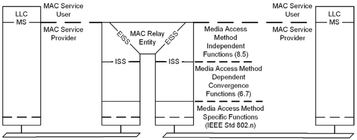
NOTE—The notation “IEEE Std 802.n” in this figure indicates that the specifications for these functions can be found in the relevant standard for the media access method concerned; for example, n would be 3 (IEEE Std 802.3) in the case of Ethernet.
Figure 6-1—Internal organization of the MAC sublayer
The MAC Sublayer comprises
a) Media access method-specific functions $^{15}$ that realize transmission and reception of MAC Protocol Data Units (MPDUs);
b) Media access method-dependent convergence functions that use item a) to provide a media access method-independent service;
c) Media access method-independent functions that use a media-independent service to provide the same or another media-independent service.
A MAC Bridge's MAC Relay Entity forwards frames between the instances of the media-independent ISS (IEEE Std 802.1AC).
A VLAN Bridge's MAC Relay Entity forwards frames between the instances of the media-independent EISS (6.8). The EISS is provided by the functions specified in 6.9 using the media-independent ISS (IEEE Std 802.1AC). The convergence functions that provide the ISS using the media-specific functions for each IEEE 802 LAN MAC type are specified in IEEE Std 802.1AC.
This clause
d) Summarizes basic architectural concepts and terms used throughout this standard, introduces the primitives and parameters of the MAC Service, and defines VLANs in terms of the connectivity provided to service users (IEEE Std 802.1AC, 6.2, 6.3);
e) Describes how Bridges preserve and maintain the quality of the MAC Service (6.4, 6.5);
f) Specifies the MAC ISS and MAC status parameters, their support by specific media access methods (IEEE Std 802.1AC), and support for signaled priority (IEEE Std 802.1AC, 6.14, 6.15, 6.20);
g) Specifies the EISS used by VLAN-aware stations, the encoding of VID and priority parameters in transmitted frames, and the classification of received frames that do not explicitly convey those parameters (6.8, 6.9, 6.12); and
h) Specifies how entities defined in terms of the ISS can support the EISS (6.17).
6.1 Basic architectural concepts and terms
The architectural concepts used in this and other IEEE 802.1 standards are based on the layered protocol model introduced by the OSI Reference Model (ISO/IEC 7498-1) and used in the MAC Service definition (IEEE Std 802.1AC), in IEEE Std 802, in other IEEE 802 standards, and elsewhere in networking. IEEE 802.1 standards in particular have developed terms and distinctions useful in describing the MAC Service and its support by protocol entities within the MAC Sublayer. $^{16}$ For further detailed discussion of these concepts and terms, see IEEE Std 802.1AC.
6.2 Provision of the MAC Service
The MAC Service provided in end stations attached to MAC Bridged Networks and Virtual Bridged Networks is the (unconfirmed) connectionless mode MAC Service defined in IEEE Std 802.1AC. The MAC Service is defined as an abstraction of the features common to a number of specific MAC Services; it describes the transfer of user data between source and destination end stations, via MA-UNITDATA request primitives and corresponding MA-UNITDATA indication primitives issued at MAC Service Access Points (MSAPs). Each MA-UNITDATA request and indication primitive has four parameters: Destination Address, Source Address, MAC Service data unit (MSDU), and Priority.
NOTE 1—The primitives of the MAC Service are closely aligned with those of the ISS (IEEE Std 802.1AC).
In a MAC Bridged Network, MAC Bridges provide a single instance of the MAC Service for the network as a whole—a single LAN, as defined in IEEE Std 802.1AC—by forwarding between the individual LANs that compose the network, though frames with specified group destination addresses are confined to individual LANs.
NOTE 2—MAC Bridges can be configured to completely partition a bridged network, though that is rarely intended.
In a Virtual Bridged Network, VLANs are defined in terms of the connectivity associations (IEEE Std 802.1AC) supported by the network: if service requests made at two different MSAPs both result in service indications at any third MSAP, then the two MSAPs are transmitting on the same VLAN; and if the service requests made at any given MSAP can result in service indications at either (or both) of two MSAPs, then those two MSAPs are receiving on the same VLAN. When only two MSAPs are in bidirectional communication, they are using the same VLAN for both transmit and receive if a third station could be added in such a way that it would receive transmissions from both.
NOTE 3—This definition of a VLAN accommodates an unavoidable and sometimes useful consequence of configuration possibilities: use of a single MSAP can result in transmission on one VLAN and reception on another.
NOTE 4—Protocol VLAN classification can be used to classify frames transmitted from a single MSAP into separate VLANs. Where protocol classification is used, the preceding rules apply to frames of a single classification.
6.2.1 Point-to-point, multipoint-to-multipoint, and rooted-multipoint connectivity
The types of connectivity supported by associations of Bridge Ports in Virtual Bridged Networks are often classified into three categories: point-to-point, multipoint-to-multipoint, and rooted-multipoint. Point-to-point connectivity is an association of exactly two Bridge Ports such that an ingress frame (for a given VLAN) at one Bridge Port may result in an egress frame at the other Bridge Port. Multipoint-to-multipoint connectivity is an association of two or more Bridge Ports such that an ingress frame at one Bridge Port may result in an egress frame at any or all of the other Bridge Ports. Rooted-multipoint connectivity is an association of two or more Bridge Ports where each Bridge Port is designated as either a Root or a Leaf Port, and an ingress frame at a Root Port may result in an egress frame at any or all Leaf Ports and other Root Ports, while an ingress frame at a Leaf Port may result in an egress frame at any or all Root Ports but never results in an egress frame at another Leaf Port. Note that point-to-point connectivity is a special case of the more general multipoint-to-multipoint connectivity, and that both point-to-point connectivity and multipoint-to-multipoint connectivity are special cases of rooted-multipoint connectivity where all Bridge Ports are designated as Root Ports.
6.3 Support of the MAC Service
In a MAC Bridged Network at most one LAN can be supported on each of the individual LANs that, bridged together, compose the network. On the individual LANs of a Virtual Bridged Network, frames for different VLANs can be distinguished by the addition of a VLAN tag as the initial octets of a frame's MSDU.
When a VLAN-unaware end station is attached to an individual LAN, it will transmit and receive only untagged frames, and thus uses the VID(s) assigned by the Bridge Ports that classify those frames.
NOTE 1—Where there are only two stations attached to an individual LAN, each can assign received untagged frames to a different VID. However, such assignments can defeat the operation of network configuration protocols and can only be recommended at the edge of a network to facilitate initial classification of untagged frames transmitted by VLAN-unaware end stations. Otherwise, a change in a frame's VID can severely impact network operation by introducing frame forwarding loops. The same considerations apply to the use of protocol VLAN classification. The use of different VID assignments by Bridge Ports attached to the same LAN is usually a network configuration error.
NOTE 2—The LLC Entity in a VLAN-unaware end station can receive MAC Service indications that correspond to the receipt of VLAN-tagged frames but, being unable to recognize the tag's EtherType value, will discard the frame and not deliver it to any LLC User.
A VLAN-aware end station can use the EISS Multiplex Entity (6.17) to provide multiple SAPs, one per VID of interest, to separate MAC Clients.
The objective of Bridge operation is to maximize the availability of the MAC Service to end stations and to assist in the maintenance of the network. Bridges can be configured to provide redundant paths between end stations, enabling the network to continue providing service in the event of component failure (of Bridge or LAN). The paths supported between end stations are predictable and configurable. Group addressed (multicast and broadcast) frames for any given VLAN take the same path as frames addressed to an individual end station (unicast), thus permitting the use of either individually addressed or group addressed frames to configure or diagnose paths for frames with either group or individual destination addresses. The paths taken for frames for any given VLAN between any two stations are symmetric, i.e., frames from station A (say) to station B traverse the same Bridges and LANs as those from B to A, only in the reverse order. This symmetry reduces the probability of one-way connectivity between stations and permits the use of station location learning to localize traffic (6.5.10).
The VLAN Identifier (VID) conveyed in the VLAN tag associates each frame with the following:
a) A VLAN.
b) A loop-free active topology.
6.4 Preservation of the MAC Service
The MAC Service offered by a network consisting of LANs interconnected by Bridges is similar to that offered by a single LAN (see 6.5).
a) Frames transmitted between end stations carry the MAC addresses of the peer-end stations in their destination and source address fields, not an address of a Bridge. The MAC Relay is not directly addressed by communicating end stations.
b) The MAC addresses of end stations are not restricted by the network's topology or configuration.
c) All MAC addresses need to be unique within a VLAN, and within any set of VLANs for which filtering information is shared by a Bridge.
6.5 Quality of service (QoS) maintenance
6.5.1 Service availability
Service availability is measured as that fraction of some total time during which the MAC Service is provided. The operation of a Bridge can increase or lower the service availability.
The service availability can be increased by automatic reconfiguration of the network in order to avoid the use of a failed component (e.g., repeater, cable, or connector) in the data path. The service availability can be lowered by failure of a Bridge, through denial of service by the Bridge, or through frame filtering by the Bridge. Changes in topology, caused by component failures, the addition or removal of components, or administrative changes, are detected and signaled by the following means:
a) Physical detection of component failure and signaling of that failure by the EISS (6.8 and 6.9);
b) Detection of component failure through the operation of a spanning tree algorithm and protocol;
c) Explicit signaling of reconfiguration events through the operation of a spanning tree algorithm and protocol.
NOTE 1—Each reference to spanning tree algorithms and protocols throughout Clause 6 includes any whose purpose is to verify that each transmitted frame gives rise to at most one service indication at any of the MSAPs for which frames for that LAN or VLAN are to be received. Such protocols include RSTP (13.4), MSTP (13.5), and SPB (Clause 27).
Automatic reconfiguration can be achieved rapidly on the detection of a physical topology change (see Clause 13), thus minimizing any service denial that is caused by the reconfiguration.
A Bridge may deny service and discard frames (6.5.2) in order to preserve other aspects of the MAC Service (6.5.3 and 6.5.4) when automatic reconfiguration takes place. Service may be denied to end stations that do not benefit from the reconfiguration; hence, the service availability is lowered for those end stations. Bridges may filter frames in order to localize traffic in the network. Should an end station move, it may then be unable to receive frames from other end stations until the filtering information held by the Bridges is updated.
To minimize the effects of service denial caused by reconfiguration events, filtering information that has been dynamically learned can be modified when automatic reconfiguration takes place, or in preparation for future reconfiguration events (Clause 13 and 13.16). However, filtering information that is statically configured cannot be modified in this way.
A Bridge may deny service and discard frames in order to prevent access to the network by devices that are not authorized for such access.
To maximize the service availability, no loss of service or delay in service provision should be caused by Bridges, except as a consequence of a failure, removal, or insertion of a network component; or as a consequence of the movement of an end station; or as a consequence of an attempt to perform unauthorized access. These events are regarded as extraordinary. The operation of any additional protocol necessary to maintain the quality of the MAC Service is thus limited to the configuration of the network and is independent of individual instances of service provision.
NOTE 2—This is true only in circumstances where admission control mechanisms are not present, i.e., where the Bridges provide a “best effort” service.
NOTE 3—The operation of management on the Bridge can result in the Bridge being reset, either as a result of a specific Bridge reset operation or as a consequence of manipulating the Bridge's configuration. From the point of view of service availability, resetting the Bridge is an extraordinary event that has a similar effect to physical removal of the Bridge from the network, followed by reinsertion of the Bridge into the network.
6.5.2 Frame loss
The MAC Service does not guarantee the delivery of Service Data Units (SDUs). Frames transmitted by a source station arrive, uncorrupted, at the destination station with high probability. The operation of a Bridge introduces minimal additional frame loss.
A frame transmitted by a source station can fail to reach its destination station as a result of
a) Frame corruption during physical layer transmission or reception.
b) Frame discard by a Bridge because
1) It is unable to transmit the frame within some maximum period of time and, hence, must discard the frame to prevent the maximum frame lifetime (6.5.6) from being exceeded.
2) It is unable to continue to store the frame due to exhaustion of internal buffering capacity as frames continue to arrive at a rate in excess of that at which they can be transmitted.
3) The size of the SDU carried by the frame exceeds the maximum supported by the MAC procedures employed on the LAN to which the frame is to be relayed.
4) Changes in the connected topology of the network necessitate frame discard for a limited period of time to maintain other aspects of QoS (13.16).
5) The device attached to the Bridge is not authorized for access to the network.
6) The configuration of Static Filtering Entries or Static VLAN Registration Entries in the FDB (8.8.1, 8.8.2) disallows the forwarding of frames with particular destination addresses or VLAN classifications on specific Ports.
7) A flow metering algorithm (8.6.5) determines that discard is necessary.
NOTE—As Static Filtering Entries and Static VLAN Registration Entries are associated with particular Ports or combinations of Ports, there is a possibility that misconfiguration of such entries will lead to unintended frame discard during or following automatic reconfiguration of the network.
6.5.3 Frame misordering
The MAC Service (IEEE Std 802.1AC) permits a negligible rate of reordering of frames with a given priority for a given combination of destination address, source address, and flow hash, if present, transmitted on a given VLAN. MA_UNITDATA.indication service primitives corresponding to MA_UNITDATA.request primitives, with the same requested priority and for the same combination of VLAN classification, destination address, source address, and flow hash, if present, are received in the same order as the request primitives were processed.
NOTE 1—The operation of the Forwarding Process in Bridges (8.6) is such that the frame-ordering characteristics of the MAC Service are preserved.
Where Bridges in a network are capable of connecting the individual MACs in such a way that multiple paths between any source station–destination station pairs exist, the operation of a protocol is required to ensure that a single path is used for every sequence of frames whose order must be maintained.
NOTE 2—Where STP is in use (see Clause 8 of IEEE Std 802.1D, 1998 Edition [B9]), frame misordering cannot occur during normal operation. When a protocol that is capable of rapid reconfiguration after network component failure (such as RSTP, MSTP, or SPB) is used, there is an increased probability that frames that are in transit through the network will be misordered, because a Bridge can buffer frames awaiting transmission through its Ports. The probability of misordering occurring as a result of such an event is dependent on implementation choices and is associated with reconfiguration events. Some known LAN protocols, for example, LLC Type 2 (ISO/IEC 8802-2), are sensitive to frame misordering and duplication; in order to allow Bridges that support RSTP to be used in environments where sensitive protocols are in use, the forceVersion parameter (13.7.2) can be used to force a Bridge that supports RSTP to operate in an STP-compatible manner. A more detailed discussion of misordering in RSTP can be found in K.3 of IEEE Std 802.1D-2004 [B10].
6.5.4 Frame duplication
The MAC Service (IEEE Std 802.1AC) permits a negligible rate of duplication of frames. The operation of Bridges introduces a negligible rate of duplication of user data frames.
The potential for frame duplication in a bridged network arises through the possibility of the following:
a) Repeated transmission, through a given Bridge Port, of a frame received on another Bridge Port;
b) Multiple paths between source and destination end stations;
c) A loop in a path between source and destination stations.
A Bridge does not transmit any received frame more than once through any Port (8.6.7).
When Bridges in a network connect individual LANs in such a way that physical topology is capable of providing multiple paths between any source and destination, a protocol is required to ensure that the active topology comprises a single path. SST Bridges assign all frames to a single active topology, other Bridges assign frames to an active topology using the VID or VID and destination address. For frames assigned to Ethernet Switched Paths (ESPs) by PBB-TE, the protocol comprises the operation of an external agent that configures Static Filtering Entries in the FDB (see 25.10); for all other frames RSTP, MSTP, or Intermediate System to Intermediate System Protocol for Shortest Path Bridging (ISIS-SPB) is used to configure the controls used for active topology enforcement (8.6.1). Reception of duplicate copies of a single transmitted frame can be avoided by loop prevention (6.5.4.1) or loop mitigation (6.5.4.2).
NOTE—Where RSTP, MSTP, or SPB is used (see Clause 13), there is a probability that a reconfiguration event can cause frames that are in transit through the network to be duplicated, because a Bridge can buffer frames awaiting transmission through its Ports. As the probability of duplication occurring as a result of such an event is small, and the frequency of reconfiguration events is also small, the degradation of the properties of the MAC Service caused by this source of frame duplication is considered to be negligible. A more detailed discussion of frame duplication in RSTP can be found in K.2 of IEEE Std 802.1D-2004 [B10].
6.5.4.1 Loop prevention
Each Bridge that participates in RSTP, MSTP, or ISIS-SPB calculates a spanning tree for each active topology, and prevents loops by exchanging information between neighboring Bridges to ensure either that their topology calculations are consistent and each frame is consistently allocated to the same active topology, or that frames are not relayed.
6.5.4.2 Loop mitigation
Each Bridge that participates in SPBM may mitigate loops. The properties of loop mitigation are listed below. Allowing temporary loops to form for unicast traffic and using loop mitigation provides for faster response to topology changes. Loop mitigation is accomplished if a unicast frame can only be forwarded by the Bridges as follows:
a) From at most one reception Port to at most one transmission Port; and
b) To a different transmission Port from the reception Port;
and
c) Each Bridge does not relay, from any reception Port, a frame whose source address and VID are the same as that used by any entity within the Bridge; and
d) Each Bridge does not transmit, through any Port, a frame whose destination address and VID are the same as that used by any entity within the Bridge;
and
e) All LANs in the network provide only point-to-point connectivity.
Loop mitigation limits the effect of loops since any loop in the active topology cannot include either the source or destination of the frame, nor can the loop cause multiple copies of the initial frame to be delivered to the destination, or to or from any LAN in the network that is not part of the loop.
Loop mitigation does not require that neighboring Bridges assign a given frame to the same active topology; or even that the reception and transmission Ports for that frame have been derived from the same topology calculation within a given Bridge. While this standard specifies the calculation of paths that are reverse path congruent (Clause 3) to support bidirectional communication, that property has no bearing on loop mitigation. As a consequence, the Dynamic Filtering Entries that are used for active topology enforcement (8.6.1) and loop mitigation with SPBM (27.4.1) can be updated one at a time after ISIS-SPB has completed a link state calculation or during the course of that calculation.
6.5.5 Transit delay
The MAC Service introduces a frame transit delay that is dependent on the particular media and MAC method employed. Frame transit delay is the elapsed time between an MA_UNITDATA.request primitive and the corresponding MA_UNITDATA.indication primitive. Elapsed time values are calculated only on SDUs that are successfully transferred.
Since the MAC Service is provided at an abstract interface within an end station, it is not possible to specify precisely the total frame transit delay. It is, however, possible to measure those components of delay associated with media access and with transmission and reception; and the transit delay introduced by an intermediate system, in this case a Bridge, can be measured.
The minimum additional transit delay introduced by a Bridge is the time taken to receive a frame plus that taken to access the media onto which the frame is to be relayed. Note that the frame is completely received before it is relayed as the Frame Check Sequence (FCS) is to be calculated and the frame discarded if in error.
6.5.6 Frame lifetime
The MAC Service ensures that an upper bound to the transit delay is experienced for a particular instance of communication. This maximum frame lifetime is necessary to ensure the correct operation of higher layer protocols. The additional transit delay introduced by a Bridge is discussed in 6.5.5.
To enforce the maximum frame lifetime, a Bridge may be required to discard frames. Since the information provided by the MAC Sublayer to a Bridge does not include the transit delay already experienced by any particular frame, Bridges discard frames to enforce a maximum delay in each Bridge.
The value of the maximum Bridge transit delay is based on both the maximum delays imposed by all Bridges in the network and the desired maximum frame lifetime. A recommended and an absolute maximum value are specified in Table 6-1.
Table 6-1—Bridge transit delay
<table><tr><td>Parameter</td><td>Recommended value</td><td>Absolute maximum</td></tr><tr><td>Maximum Bridge transit delay</td><td>1.0s</td><td>4.0s</td></tr></table>
6.5.7 Undetected frame error rate
The MAC Service introduces a very low undetected frame error rate in transmitted frames. Undetected errors are protected against by the use of an FCS that is appended to the frame by the MAC Sublayer of the source station prior to transmission, and checked by the destination station on reception.
The FCS calculated for a given SDU is dependent on the MAC method employed. It is therefore necessary to recalculate the FCS within a Bridge providing a relay function between IEEE 802 LAN MACs of dissimilar types if differences in the method of calculation and/or the coverage of the FCS, or changes to the data that is within the coverage of the FCS, would lead to a different FCS being calculated for the SDU by the two MAC methods. This introduces the possibility of additional undetected errors arising from the operation of a Bridge. For frames relayed between LANs of the same MAC type, the Bridge shall not introduce an undetected frame error rate greater than that which would have been achieved by preserving the FCS.
NOTE—Application of the techniques described in Annex O allows an implementation to achieve an arbitrarily small increase in undetected frame error rate, even in cases where the data that is within the coverage of the FCS is changed.
6.5.8 Maximum Service Data Unit Size
The Maximum Service Data Unit Size that can be supported by an IEEE 802 LAN varies with the MAC method and its associated parameters (e.g., speed, electrical characteristics). It may be constrained by the owner of the LAN. The Maximum Service Data Unit Size supported by a Bridge between two LANs is the smaller of that supported by the LANs. No attempt is made by a Bridge to relay a frame to a LAN that does not support the size of SDU conveyed by that frame.
6.5.9 Priority
The MAC Service includes priority as a QoS parameter. MA_UNITDATA.request primitives with a high priority may be given precedence over other request primitives made at the same station, or at other stations attached to the same LAN and can give rise to earlier MA_UNITDATA.indication primitives.
The MAC Sublayer maps the requested priority onto the priorities supported by the individual MAC method. The requested priority may be conveyed to the destination station.
The transmission delay experienced by a frame in a Bridge can be managed by associating a priority with the frame.
The transmission delay comprises
a) A queuing delay until the frame becomes first in line for transmission on the Port, in accordance with the procedure for selecting frames for transmission described in 8.6.8;
b) The access delay for transmission of the frame.
Queuing delays can be managed using priority. Access delays can be managed using priority in MAC methods that support more than one priority.
The priority associated with a frame can be signaled by means of the priority signaling mechanisms inherent in some IEEE 802 LAN MAC types. Since not all IEEE 802 LAN MAC types are able to signal the priority associated with a frame, VLAN Bridges regenerate priority based on a combination of signaled information and configuration information held in the Bridge.
The Bridge maps priority values onto one or more traffic classes; Bridges that support more than one traffic class are able to support expedited classes of traffic. The Forwarding Process, 8.6, describes the use of priority and traffic classes in Bridges. Given the constraints placed on frame misordering in a Bridge, as expressed in 6.5.3, the mappings of priority and traffic class are static.
NOTE 1—The term “traffic class,” as used in this standard, is used only in the context of the operation of the priority handling and queuing functions of the Forwarding Process, as described in 8.6. Any other meanings attached to this term in other contexts do not apply to the use of the term in this standard.
The ability to signal priority in IEEE 802 LANs, coupled with a consistent approach to the mapping of priority to traffic classes, and of priority to the priority requested from the individual LAN or supporting service, allows consistent use of priority information to be made, according to the capabilities of the Bridges and MAC methods that are involved in the transmission path.
NOTE 2—This standard defines a frame format and associated procedures that can be used to carry priority information across LAN MAC types that are not able to signal priority.
Under normal circumstances, priority is not modified in transit through the relay function of a Bridge; however, there may be some circumstances where it is desirable for management purposes to control how priority is propagated. The Priority Regeneration Table (Table 6-4) provides the ability to map incoming priority values on a per-Port basis, under management control. In its default state, this table provides an identity mapping from priority values to Regenerated priority values; i.e., by default, the Regenerated priority is identical to the incoming priority.
6.5.10 Throughput
The total throughput provided by a network can be significantly greater than that provided by an equivalent single LAN. Bridges may localize traffic within the network by filtering frames. Filtering services available in bridged networks are described in 6.16.
The throughput between end stations on individual LANs, communicating through a Bridge, can be lowered by frame discard in the Bridge due to the inability to transmit at the required rate on the LAN forming the path to the destination for an extended period.
6.6 Internal Sublayer Service (ISS)
The service primitives and parameters, the status parameters, and the point-to-point parameters of the ISS are specified in IEEE Std 802.1AC.
6.6.1 Control primitives and parameters
The ISS provides two control primitives, an M_CONTROL.request and an M_CONTROL.indication, and their associated parameters.
The M_CONTROL.request primitive has the form:
M_CONTROL.request (
destination_address
opcode
request_operand_list
)
The M_CONTROL.indication primitive has the form:
M_CONTROL.indication (opcode indication_operand_list)
See 36.1.2 for a description of the M_CONTROL parameters used for PFC.
6.7 Support of the ISS by specific MAC procedures
Support of the ISS by MAC Entities that use specific IEEE 802 media access methods is specified in IEEE Std 802.1AC.
6.7.1 Support of the ISS by IEEE Std 802.3 (Ethernet)
In addition to the provisions of 12.1.1 of IEEE Std 802.1AC-2012, an M_CONTROL.request primitive is mapped to an IEEE 802.3 MA_CONTROL.request primitive having the same parameters. An IEEE 802.3 MA_CONTROL.indication primitive is mapped to an M_CONTROL.indication primitive having the same parameters.
6.8 Enhanced Internal Sublayer Service (EISS)
The EISS is derived from the ISS (IEEE Std 802.1AC) by augmenting that specification with elements necessary to the operation of the tagging and untagging functions of a VLAN Bridge (3.259). Within the attached end station, these elements can be considered either to be below the MAC Service boundary, and pertinent only to the operation of the service provider, or to be local matters not forming part of the peer-to-peer nature of the MAC Service.
The EISS provides the same service status and point-to-point parameters as the ISS (IEEE Std 802.1AC).
6.8.1 Service primitives
The unit-data primitives that define this service are
EM_UNITDATA.indication
(
destination_address,
source_address,
mac_service_data_unit,
priority,
drop_eligible,
vlan_identifier,
frame_check_sequence,
service_access_point_identifier,
connection_identifier,
flow_hash,
time_to_live
)
EM_UNITDATA.request
(
destination_address,
source_address,
mac_service_data_unit,
priority,
drop_eligible,
vlan_identifier,
frame_check_sequence,
service_access_point_identifier,
connection_identifier,
flow_hash,
time_to_live
)
The destination_address, source_address, mac_service_data_unit, priority, drop_eligible, service_access_point_identifier, connection_identifier, and frame_check_sequence parameters are as defined for the ISS.
NOTE—Some of the functions supporting the EISS may result in changes to the mac_service_data_unit or other parameters used to construct a frame. The original FCS associated with a frame is invalidated if there are changes to any fields of the frame, if fields are added or removed, or if bit ordering or other aspects of the frame encoding have changed. An invalid FCS is signaled in the EISS by an unspecified value in the frame_check_sequence parameter. This signals the need for the FCS to be regenerated according to the normal procedures for the transmitting MAC. Two options for regenerating the FCS under these circumstances are discussed in Annex O.
The vlan_identifier parameter carries the VID.
The flow_hash parameter either is null or carries a value that may be used by the forwarding process in selecting a single forwarding port from a set of available forwarding ports (8.6.3). Transmission order is maintained for all frames from a source to a destination with the same flow hash value. A flow hash value may be retrieved from an F-TAG or otherwise derived from the contents of a service primitive (44.2.2). A flow hash is not required by the MAC Relay Entity, and successful filtering can be provided without this additional information; however, it is required for flow filtering services supported by SPBM with ECMP. Any protocol entity in the interface stack that does not specify use of the flow_hash assigns the flow_hash value (if any) supplied with a request from the user of the protocol entity (or with an indication from the provider of the service used by the protocol entity) to the flow_hash on associated requests made (or indications generated) by the protocol entity.
The time_to_live parameter either is null or carries a value that may be used to filter frames that have reached their limit of permitted network hops. A time_to_live value may be retrieved from an F-TAG in the mac_service_data_unit and processed as described in 44.2.2. Any protocol entity in the interface stack that does not specify use of the time_to_live assigns the time_to_live value (if any) supplied with a request from the user of the protocol entity (or with an indication from the provider of the service used by the protocol entity) to the time_to_live on associated requests made (or indications generated) by the protocol entity.
6.8.2 Status parameters
The EISS also makes available the MAC_Enabled and MAC_Operational status parameters that reflect the operational state and administrative controls over each instance of the service provided. The values of these parameters are mapped directly from the values made available by the ISS (IEEE Std 802.1AC).
6.8.3 Point-to-point parameters
The EISS also makes available the operPointToPointMAC and adminPointToPointMAC status parameters that reflect the point-to-point status of each instance of the service provided and provide administrative control over the use of that information. The values of these parameters are mapped directly from the values made available by the ISS (IEEE Std 802.1AC).
6.8.4 Control primitives and parameters
The EISS provides two control primitives, an EM_CONTROL.request and an EM_CONTROL.indication, and their associated parameters. The values of these parameters are mapped directly to/from the values made available by the corresponding ISS primitives (6.6.1).
The EM_CONTROL.request primitive has the form:
EM_CONTROL.request (
destination_address
opcode
request_operand_list
)
The EM_CONTROL.indication primitive has the form:
EM_CONTROL.indication (opcode indication_operand_list)
6.9 Support of the EISS
The EISS is supported by tagging and detagging functions that in turn use the ISS (IEEE Std 802.1AC). Any given instance of the EISS shall be supported by using one but not both of the following VLAN tag types:
a) C-VLAN tag (C-TAG); or
b) S-VLAN tag (S-TAG);
selected as specified in 9.5.
Each Bridge Port shall support the following parameters for use by these functions:
c) an Acceptable Frame Types parameter with at least one of the following values:
1) Admit Only VLAN-tagged frames;
2) Admit Only Untagged and Priority-tagged frames;
3) Admit All frames.
d) a PVID parameter for Port-based VLAN classification;
and may support the following parameter:
e) a VID Set for Port-and-Protocol-based classification (6.12).
f) A VID translation table;
g) An Egress VID translation table.
All three values for Acceptable Frame Types may be supported; if so, they shall be configurable using the management operations defined in Clause 12, and the default shall be Admit All Frames. A frame is treated as Untagged if the initial octets of the mac_service_data_unit parameter do not contain a VLAN tag of the type used to support the EISS (9.5), as Priority-tagged if the value contained in the VID field of the VLAN tag is zero, and as VLAN-tagged if the value is nonzero.
NOTE 1—The VID translation tables are for use only at the edge of administrative or control protocol domains, e.g., Network-Network Interfaces, SPB domains, or Root and Leaf interfaces to a rooted-multipoint service, as described in this standard. Control protocols that are designed for operation through ports where VID translation is permitted (e.g., MSTP, MVRP, CFM) explicitly compensate for the translation of VID values carried within their PDUs. Successful operation and maintenance of Bridged Networks depends on the fact that VID values are not translated at other ports or at ports within the operational span of control protocols that do not recognize translation.
The PVID and VID Set shall contain valid VID values (Table 9-2) and may be configured by management. If they have not been explicitly configured, the PVID shall assume the value of the default PVID defined in Table 9-2 and the VID Set shall be empty.
NOTE 2—The default behavior of a Bridge that supports Port-and-Protocol-based classification is the same as that of a Bridge that supports only Port-based classification, since all the Protocol Group Identifiers in the VID Set for each Port assign the same VID as the PVID.
The VID translation table and Egress VID translation table provide a mapping between “local VID” values and “relay VID” values. The local VID is the value encoded in a VLAN tag header in the initial octets of the mac_service_data_unit parameter of an ISS service primitive (M_UNITDATA.indication or M_UNITDATA.request). The relay VID is the value contained in the vlan_identifier parameter of an EISS service primitive (EM_UNITDATA.indication or EM_UNITDATA.request). The VID translation table may be supported by itself, or in combination with the Egress VID translation table. When only the VID translation table is supported it is used for bidirectional mapping between the local VID and the relay VID in both indication and request service primitives. This enforces a symmetric one-to-one translation (i.e., if local VID A maps to relay VID B then relay VID B will map to local VID A). When both tables are supported the VID translation table is used only for mapping the local VID to a relay VID in indication service primitives, and the Egress VID translation table is used for mapping the relay VID to a local VID in request service primitives. This allows asymmetric and many-to-one translations (e.g., for translating to and from SPVIDs at the edge of an SPT Region). Both tables are configurable by management, and the default configuration maps each value of the local VID to the same value for the relay VID, and vice versa. For Bridge Ports at the boundary of an SPBV SPT Region the tables are dynamically modified by the ISIS-SPB.
6.9.1 Data indications
On receipt of an M_UNITDATA.indication primitive from the ISS, the received frame is discarded if
a) The initial octets of the mac_service_data_unit do not contain a valid VLAN tag header (9.3) of the type used to support the EISS (9.5), and the Acceptable Frame Types is Admit Only VLAN-tagged frames; or
b) The initial octets of the mac_service_data_unit contain a valid VLAN tag header (9.3) of the type used to support the EISS (9.5), and
1) The VID value is FFF, reserved in Table 9-2 for future implementation use; or
2) The VID translation table is supported and the translated VID value (relay VID) is FFF (indicating local discard); or
3) The VID value is 000 (indicating Priority-tagged), and the Acceptable Frame Types is Admit Only VLAN-tagged frames; or
4) The VID value is in the range 001-FFE, and the Acceptable Frame Types is Admit Only Untagged and Priority-tagged frames.
Otherwise, an EM_UNITDATA.indication primitive is invoked, with parameter values determined as follows:
The destination_address, source_address, and frame_check_sequence parameters carry values equal to the corresponding parameters in the received data indication. The values of the remaining parameters are affected by the contents of the tag header if the frame contains a VLAN tag of the type supported by this instance of the EISS.
The value of the mac_service_data_unit parameter is as follows:
c) If the frame is tagged, then the value used is equal to the value of the received mac_service_data_unit following removal of the tag header.
d) Otherwise, the value used is equal to the value of the received mac_service_data_unit.
The value of the vlan_identifier parameter is as follows:
e) The value contained in the VID field, optionally translated using the VID translation table, if the frame is VLAN-tagged;
f) The value of the PVID for the Port, if Port-and-Protocol-based VLAN classification is not supported and the frame is untagged, Priority-tagged, or the VID translation table is supported and the translated VID value (relay VID) is zero;
g) As determined by Port-and-Protocol-based VLAN classification (6.12) if that capability is implemented and the frame is untagged or Priority-tagged or the VID translation table is supported and the translated VID value (relay VID) is zero.
The value of the drop_eligible and priority parameters are determined as follows:
h) If the frame is tagged, the value of the drop_eligible parameter and the received priority value are decoded from the tag header as described in 6.9.3. Otherwise,
i) The received priority value and the drop_eligible parameter value are the values in the M_UNITDATA.indication.
j) The value of the priority parameter is then regenerated from the received priority, as specified in 6.9.4.
6.9.2 Data requests
On invocation of an EM_UNITDATA.request primitive by a user of the EISS, the frame is discarded if the Egress VID translation table is supported and the translated VID value (local VID) is FFF (reserved in Table 9-2). Otherwise, an M-UNITDATA.request primitive is invoked, with parameter values as follows:
The destination_address, source_address, drop_eligible, and priority parameters carry values equal to the corresponding parameters in the received data request.
Unless the Bridge Port is a member of the untagged set (8.8.2) for the VID identified by the vlan_identifier parameter, then a tag header, formatted as necessary for the destination MAC type, is inserted as the initial octets of the mac_service_data_unit parameter. The values of the vlan_identifier (optionally translated using the VID translation table or Egress VID translation table), priority, and drop_eligible parameters are used to determine the contents of the tag header, in accordance with Clause 9.
If the Bridge Port is a member of the untagged set (8.8.2) for the VID identified by the vlan_identifier parameter, no tag header is inserted.
The remaining octets of the mac_service_data_unit parameter are those accompanying the EISS-request. If the data request is a consequence of relaying a frame and the MAC type of the Port differs from that used to receive the frame, they are modified, if necessary, in accordance with the procedures described in ISO/IEC 11802-5, IETF RFC 1042 (1988), and IETF RFC 1390.
The value of the frame_check_sequence parameter is determined as follows:
a) If the frame_check_sequence parameter received in the data request either is unspecified or still carries a valid value, then that value is used.
b) Otherwise, the value used is either unspecified or derived from the received FCS information by modification to take account of the conditions that have caused it to become invalid.
6.9.3 Priority Code Point encoding
The priority and drop_eligible parameters are encoded in the PCP field of the VLAN tag using the Priority Code Point Encoding Table for the Port, and they are decoded from the PCP using the Priority Code Point Decoding Table. For each Port, the Priority Code Point Encoding Table has 16 entries, corresponding to each of the possible combinations of the eight possible values of priority (0 through 7) with the two possible values of drop_eligible (True or False). For each Port, the Priority Code Point Decoding Table has 8 entries, corresponding to each of the possible PCP values.
Alternative values for each table are specified as rows in Table 6-2 and Table 6-3, with each alternative labeled by the number of distinct priorities that can be communicated, and the number of these for which drop precedence can be communicated. For example, the table entries 6P2D allow six distinct priorities with drop precedence for two. The default values (8P0D) specify a PCP value equal to the priority value and do not support communication of drop precedence in the PCP field. The combination of the priority and drop_eligible parameters is shown by the priority alone if drop_eligible is False, and by the priority followed by the letters “DE” if drop_eligible is True.
If the VLAN tag is an S-TAG, then Table 6-2 and Table 6-3 shall be supported. If the VLAN tag is a C-TAG, then the 8P0D row of each table shall be supported, and the remaining rows may be supported.
NOTE—To avoid potential misordering of packets, all Ports on a LAN should select the same row of Table 6-2 and Table 6-3. Interoperability considerations with Bridges supporting only the 8P0D row are discussed in I.8.
Table 6-2—Priority Code Point encoding
<table><tr><td colspan="2">priority drop_eligible</td><td>7</td><td>7DE</td><td>6</td><td>6DE</td><td>5</td><td>5DE</td><td>4</td><td>4DE</td><td>3</td><td>3DE</td><td>2</td><td>2DE</td><td>1</td><td>1DE</td><td>0</td><td>0DE</td></tr><tr><td rowspan="4">PCP</td><td>8P0D (default)</td><td>7</td><td>7</td><td>6</td><td>6</td><td>5</td><td>5</td><td>4</td><td>4</td><td>3</td><td>3</td><td>2</td><td>2</td><td>1</td><td>1</td><td>0</td><td>0</td></tr><tr><td>7P1D</td><td>7</td><td>7</td><td>6</td><td>6</td><td>5</td><td>4</td><td>5</td><td>4</td><td>3</td><td>3</td><td>2</td><td>2</td><td>1</td><td>1</td><td>0</td><td>0</td></tr><tr><td>6P2D</td><td>7</td><td>7</td><td>6</td><td>6</td><td>5</td><td>4</td><td>5</td><td>4</td><td>3</td><td>2</td><td>3</td><td>2</td><td>1</td><td>1</td><td>0</td><td>0</td></tr><tr><td>5P3D</td><td>7</td><td>7</td><td>6</td><td>6</td><td>5</td><td>4</td><td>5</td><td>4</td><td>3</td><td>2</td><td>3</td><td>2</td><td>1</td><td>0</td><td>1</td><td>0</td></tr></table>
Table 6-3—Priority Code Point decoding
<table><tr><td colspan="2">PCP</td><td>7</td><td>6</td><td>5</td><td>4</td><td>3</td><td>2</td><td>1</td><td>0</td></tr><tr><td rowspan="4"><eq>priority</eq> drop eligible</td><td>8P0D (default)</td><td>7</td><td>6</td><td>5</td><td>4</td><td>3</td><td>2</td><td>1</td><td>0</td></tr><tr><td>7P1D</td><td>7</td><td>6</td><td>4</td><td>4DE</td><td>3</td><td>2</td><td>1</td><td>0</td></tr><tr><td>6P2D</td><td>7</td><td>6</td><td>4</td><td>4DE</td><td>2</td><td>2DE</td><td>1</td><td>0</td></tr><tr><td>5P3D</td><td>7</td><td>6</td><td>4</td><td>4DE</td><td>2</td><td>2DE</td><td>0</td><td>0DE</td></tr></table>
The values in the Priority Code Point Encoding Table and Priority Code Point Decoding Table may be modified by management, as described in Clause 12. If this capability is provided, the value of the table entries shall be independently settable for each Port. The values shall be constrained as follows:
a) For any two priority values with the same drop_eligible value, the lower priority shall not map to a higher PCP than the higher priority.
b) The lower of any two PCP values shall not map to a higher priority than the higher PCP.
c) With the exception of values 0 and 1, any priority value combined with drop_eligible True shall not map to a higher PCP than the same priority value combined with drop_eligible False.
d) With the exception of values 0 and 1, any PCP value shall not map to a priority value combined with drop_eligible True if a lower PCP maps to the same priority value combined with drop_eligible False.
The values may be further constrained, but if the tables can be modified, the default values shown in Table 6-2 and Table 6-3, and the alternative sets of values in Table 6-2 and Table 6-3 shall be settable.
The drop_eligible parameter may also be encoded in and decoded from the Drop Eligible Indicator (DEI) in the VLAN tag. Use of the DEI allows the VLAN tag to convey eight distinct priorities, each with a DEI. If this capability is provided, it shall be independently manageable for each Port by means of a Use_DEI parameter. If the Use_DEI is True for the Port, the drop_eligible parameter is encoded in the DEI of transmitted frames, and the drop_eligible parameter shall be True for a received frame if the DEI is set in the VLAN tag or the Priority Code Point Decoding Table indicates drop_eligible True for the received PCP value. If the Use_DEI parameter is False, the DEI shall be transmitted as zero and ignored on receipt. The default value of the Use_DEI parameter is False.
6.9.4 Regenerating priority
The priority of each received frame is regenerated using priority information contained in the frame and the Priority Regeneration Table for the reception Port. For each reception Port, the Priority Regeneration Table has eight entries, corresponding to the eight possible values of priority (0 through 7). Each entry specifies, for the given value of received priority, the corresponding regenerated value.
For untagged frames, the priority parameter signaled in the corresponding M_UNITDATA.indication is taken to be the received priority. For tagged frames, the priority signaled in the PCP field of the tag header is taken to be the received priority.
NOTE 1—IEEE 802 LAN technologies signal a maximum of eight priority values. Annex I further explains the use of priority values and how they map to traffic classes.
Table 6-4 specifies default regenerated priority values for each of the eight possible values of the received priority. These default values shall be used as the initial values of the corresponding entries of the Priority Regeneration Table for each Port.
The values in the Priority Regeneration Table may be modified by management, as described in Clause 12. If this capability is provided, the value of the table entries shall be independently settable for each reception Port and for each value of received priority, and the Bridge shall have the capability to use the full range of values in the parameter ranges specified in Table 6-4.
NOTE 2—The regeneration and mapping of priority within the Bridge should be consistent with the end-to-end significance of that priority across the rest of the Bridged Network. The regenerated priority value is used:
— Via the traffic class table (8.6.6) to determine the traffic class for a given outbound Port, and
— Via fixed, MAC type-specific mappings (IEEE Std 802.1AC) to determine the access priority that will be used for certain media access methods.
Table 6-4—Priority regeneration
<table><tr><td>Received priority</td><td>Default regenerated priority</td><td>Range</td></tr><tr><td>0</td><td>0</td><td>0–7</td></tr><tr><td>1</td><td>1</td><td>0–7</td></tr><tr><td>2</td><td>2</td><td>0–7</td></tr><tr><td>3</td><td>3</td><td>0–7</td></tr><tr><td>4</td><td>4</td><td>0–7</td></tr><tr><td>5</td><td>5</td><td>0-7</td></tr><tr><td>6</td><td>6</td><td>0–7</td></tr><tr><td>7</td><td>7</td><td>0–7</td></tr></table>
In Bridges that support SRP, an SRP domain boundary port priority regeneration override table is maintained for each reception Port. This table associates a priority value with each SR class supported by the Bridge, and specifies the priority value to be used as the regenerated priority, in preference to the value in the
Priority Regeneration table, when the SRPdomainBoundaryPort parameter (35.1.4) for that SR class has the value TRUE. Table 6-5 specifies the default values for priority and regenerated priority for two SR classes, SR class A and SR class B. In cases where only SR class B is supported, only the default value shown in the table for SR Class B is used.
Table 6-5—Default SRP domain boundary port priority regeneration override values
<table><tr><td>SR class</td><td>Default priority</td><td>Default regenerated priority for SRP domain boundary Ports</td><td>Range</td></tr><tr><td>A</td><td>3</td><td>0</td><td>0–7</td></tr><tr><td>B</td><td>2</td><td>0</td><td>0–7</td></tr></table>
The priority values contained in the SRP domain boundary port priority regeneration override table may be modified by management, as described in Clause 12. If this capability is provided, the value of the table entries shall be independently settable for each reception Port and for each supported SR class, and the Bridge shall have the capability to use the full range of values in the parameter ranges specified in Table 6-5.
NOTE 3—The default values specified for the SRP domain boundary port Priority Regeneration Table map inbound PCP values onto the next lowest priority that is available, leaving the remaining priority values unchanged. The consequence of this remapping is that traffic entering an SRP domain that carries the priority value associated with that domain is forwarded by the Bridge at the domain boundary using a lower priority. There is no means of mapping these priority values back to their original values as frames exit from an SRP domain. The default mappings are based on the assumption that normally, two SR classes (A and B) are used to support traffic for which bandwidth has been reserved; if only the lower class (B) is supported, then the default override value for the unsupported A class does not apply.
NOTE 4—The ability for the priority regeneration table to be freely modified by management means that it is possible to create mappings that result in reserved and nonreserved traffic sharing the same priority. This will have unpredictable effects upon the behavior of the network with respect to the worst-case latency that can be assumed for reserved traffic.
6.10 Support of the ISS/EISS by PIPs
Each PIP on a BEB uses a single ISS-SAP (IEEE Std 802.1AC) and the I-TAG (9.5) to provide a separate Bridge Port (the VIP) for each backbone service instance configured for the PIP. Each VIP supports either the VLAN-unaware MAC Relay Entity of a T-component or the VLAN-aware MAC Relay Entity of an I-component. A single VIP ISS-SAP is provided to a T-component. An I-component uses an EISS-SAP, supported by its own instance of the functions specified in 6.9 with the S-TAG (9.5), for each VIP ISS-SAP. See Figure 6-2.
The EISS of each Virtual Instance Port (VIP-EISS) shall be supported by an instance of the functions of 6.9 using the S-TAG type (9.5). The ISS of all of the Virtual Instance Ports (VIP-ISS) shall be supported by a single instance of the functions specified in this subclause using the I-TAG type (9.5).
NOTE 1—Higher Layer Entities may interface to any VIP and/or the PIP at the Service Access Points (SAPs) represented by any VIP-ISS and/or the PIP-ISS using the Bridge Port Connectivity specified in 8.5.1. Protocol shims such as CFM MPs may interface at any VIP-EISS using the EISS Multiplex Entity specified in 6.17, or at the PIP-ISS using the Backbone Service Instance Multiplex Entity specified in 6.18. Figure 26-2 shows a PIP with both Bridge Port Connectivity and CFM shims.
Each PIP shall have an individual Backbone Media Access Control (B-MAC) address referred to as the PIP MAC address (26.4) for use by the functions specified in this subclause.
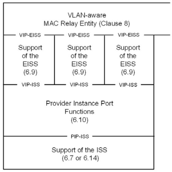
I-component
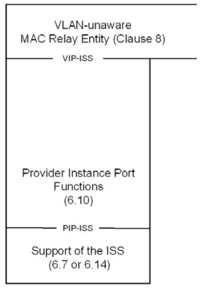
T-component
Figure 6-2—Provider Instance Ports (PIPs)
Each VIP shall support the following parameters for use by these functions:
a) A VIP-ISID parameter for the I-SID of the backbone service instance associated with this VIP;
b) A Default Backbone Destination;
c) An adminPointToPointMAC;
d) An enableConnectionIdentifier.
The VIP-ISID shall contain a valid I-SID value (9.7), which is configured by management.
The Default Backbone Destination parameter contains a MAC address to be used in the destination_address parameter of an M_UNITDATA.request at the PIP-ISS when a backbone destination address cannot be derived from the connection_identifier parameter of the M_UNITDATA.request from the VIP-ISS. The default value of the Default Backbone Destination is the Backbone Service Instance Group address for the VIP-ISID (generated by concatenating the Provider Backbone Bridge (PBB) organizationally unique identifier (OUI) with the VIP-ISID value as specified in 26.4).
The adminPointToPointMAC parameter of the VIP-ISS reflects the point-to-point status of the backbone service instance associated with the VIP. The default value of the adminPointToPointMAC parameter is ForceFalse. The value may be configured by management to ForceTrue when instantiating a VIP for a point-to-point backbone service instance. A value of ForceFalse or Auto results in a operPointToPointMAC value of FALSE; a value of ForceTrue results in a operPointToPointMAC value of TRUE. Whenever the operPointToPointMAC parameter transitions to FALSE, the value for the Default Backbone Destination parameter is set to the Backbone Service Instance Group address for the VIP-ISID. When the operPointToPointMAC parameter is TRUE, the Default Backbone Destination parameter is modified by subsequent M_UNITDATA.indications as specified in 6.10.1 (and described in 26.4.1).
The enableConnectionIdentifier parameter allows the VIP to use the connection_identifier parameter to learn associations between a B-MAC address and a Customer Media Access Control (C-MAC) address. The default value is TRUE. This parameter should be configured to FALSE at the root node of a point-to-multipoint TESI.
NOTE 2—There is a 1:1 relationship between a given value of the connection_identifier and a B-MAC address. This level of indirection is provided to allow the use of the connection_identifier parameter for other purposes by other types of Bridge Ports. The relationship between a given connection_identifier value and a B-MAC address is maintained as long as any FDB entry contains this value for the connection_identifier. No ageing mechanism other than that specified for Dynamic Filtering Entries is implied.
6.10.1 Data indications
On receipt of an M_UNITDATA.indication primitive from the PIP-ISS, if the PIP is congestion aware (5.4.1.4) and the initial octets of the mac_service_data_unit contain a valid CNM encapsulation, the received frame is processed according to 32.16. Otherwise, the received frame shall be discarded if
a) The initial octets of the mac_service_data_unit do not contain a valid I-TAG header; or
b) The Use Customer addresses (UCA) bit in the I-TAG is not zero; or
c) The Res2 field in the I-TAG is not zero; or
d) The I-SID value in the I-TAG does not match the VIP-ISID parameter for one of the VIPs supported by this PIP; or
e) The destination_address parameter of the received M_UNITDATA.indication primitive does not match one of the following:
1) The PIP MAC address; or
2) A Backbone Service Instance Group address; or
3) The broadcast address.
NOTE 1—The generation of I-tagged frames specified in 6.10.2 and the allowed manipulation of backbone addresses specified in 6.11 never result in an I-tagged frame with a broadcast destination address. The broadcast address is included in the previous list on the principle that the broadcast address is a valid address at any reception port by definition.
The received frame may be discarded if
f) The source_address parameter of the received M_UNITDATA.indication primitive is the PIP MAC address.
Otherwise, an M_UNITDATA.indication primitive is invoked at the VIP-ISS with a VIP-ISID value matching the I-SID in the I-TAG. The parameter values of the indication are determined as follows:
The destination_address parameter contains the value of the encapsulated C-DA field of the I-TAG.
The source_address parameter contains the value of the encapsulated C-SA field of the I-TAG.
If enableConnectionIdentifier is TRUE, then the connection_identifier parameter references the value of the source_address parameter (B-SA) of the M_UNITDATA.indication primitive received from the PIP-ISS; otherwise, the connection_identifier parameter is null. The connection_identifier parameter in the M_UNITDATA.indication primitive received from the PIP-ISS is ignored.
NOTE 2—The connection_identifier has only local significance meaning that it is used only at a specific PIP. The only requirement imposed by this subclause is that the connection_identifier uniquely identifies an individual B-MAC address. Whether the connection_identifier takes the value of that address, or a value from which that address can be determined, is an implementation decision that is not externally observable.
If the value of the operPointToPointMAC parameter of the VIP-ISS is TRUE, then the Default Backbone Destination parameter is set to the value of the source_address parameter of the M_UNITDATA.indication primitive.
The service_access_point_identifier parameter contains a value that uniquely identifies the VIP within the I-component. This is a local value that is used only within the I-component, and is used by the relay functions (Clause 8) as the port number of the VIP. The service_access_point_identifier parameter received in the M_UNITDATA.indication primitive is ignored.
The value of the drop_eligible and priority parameters are decoded from the I-PCP and I-DEI fields of the I-TAG as described in 6.10.3.
The value of the mac_service_data_unit parameter is the value of the received mac_service_data_unit following the removal of the I-TAG.
The value of the frame_check_sequence parameter is either unspecified or derived from the received FCS information modified to take into account the changes to the frame.
6.10.2 Data requests
On invocation of an M_UNITDATA.request primitive at any VIP-ISS, an M_UNITDATA.request primitive is invoked at the PIP-ISS, with parameter values as follows:
If enableConnectionIdentifier is TRUE, the connection_identifier is not null, and the connection_identifier references an address retained by the PIP, then the value for the destination_address is the address referenced by the connection_identifier. Otherwise, the value for the destination_address is the contents of the Default Backbone Destination parameter of the VIP.
The value for the source_address is the PIP MAC address.
The priority and drop_eligible parameters carry the same value as the corresponding parameter in the VIP-ISS request.
The connection_identifier parameter is NULL.
The mac_service_data_unit parameter is constructed from the mac_service_data_unit of the M_UNITDATA.request primitive from the VIP-ISS by prepending an I-TAG as follows:
a) The encapsulated C-SA field is the value of the source address parameter of the VIP-ISS request;
b) The encapsulated C-DA field is the value of the destination_address parameter of the VIP-ISS request;
c) The UCA, Res1, and Res2 fields are all zero;
d) The I-SID field is the value contained in the VIP-ISID parameter;
e) The I-PCP and I-DEI fields are encoded from the priority and drop_eligible parameters of the VIP-ISS request as specified in 6.10.3.
The value of the frame_check_sequence parameter is either unspecified or derived from the received FCS information modified to take into account the changes to the frame.
6.10.3 Priority Code Point encoding
The encoding (and decoding) of the I-PCP and I-DEI fields from (to) the priority and drop_eligible parameters is accomplished using a Priority Code Point Encoding Table (and Priority Code Point Decoding Table) as described in 6.9.3.
6.11 Support of the EISS by CBPs
The functions specified in this subclause replace the functions specified in 6.9 when the EISS is supported by a CBP in a BEB (Clause 25). See Figure 6-3. The functions specified in this subclause use a single instance of the ISS (IEEE Std 802.1AC) and provide a single instance of the EISS. The EISS shall be supported by functions using both the S-TAG and the I-TAG as specified in 9.5.
NOTE 1—Although the CBP does not transmit or receive S-tagged frames, it supports the S-TAG type in the sense that it is a port on an S-VLAN component and the vlan_identifier parameter contains a S-VID.
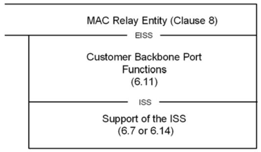
Figure 6-3—B-Component CBP
NOTE 2—Higher Layer Entities may interface to the CBP at the SAP represented by the ISS using the Bridge Port Connectivity specified in 8.5.1. Protocol shims such as CFM MPs may interface at the EISS using the EISS Multiplex Entity specified in 6.17, or at the ISS using the Backbone Service Instance Multiplex Entity specified in 6.18. Figure 26-2 shows a CBP with both Bridge Port Connectivity and CFM shims.
The CBP shall support the following parameters for use by these functions:
a) A PVID parameter for Port-based B-VLAN classification;
b) A Backbone Service Instance table.
The PVID shall contain a valid VID value (Table 9-2) and may be configured by management. If it has not been explicitly configured, the PVID shall assume the value of the default PVID defined in Table 9-2.
The Backbone Service Instance table is configurable by management and has one entry for each backbone service instance supported on the CBP. The Backbone Service Instance table is used to filter frames containing an I-SID value that is not configured on this CBP. It may also be used to provide backbone service instance-specific assignment of a B-VID, to translate I-SID values, and/or to translate backbone destination addresses. Entries in the Backbone Service Instance table may be set automatically by the protection switching procedures described in 26.10.3.4. The Backbone Service Instance table shall contain the following field for each entry:
c) Backbone-SID (I-SID). This contains the identifier used in the backbone network for the backbone service instance.
The Backbone Service Instance table may also contain one or more of the following additional fields for each entry:
d) B-VID (Backbone VLAN Identifier). If the B-VID field is supported, it shall contain a valid VID value (Table 9-2) for that backbone service instance. The default value is the same as the PVID.
e) Local-SID (Local Service Instance Identifier). This field is used to perform a bidirectional 1:1 mapping between the Backbone-SID (contained in the I-TAG in the mac_service_data_unit at the
EISS) and the Local-SID (contained in the I-TAG in the mac_service_data_unit at the ISS). The default value of the Local-SID field is the value of the Backbone-SID field.
f) Default Backbone Destination. If this field is present, it is used as the destination_address in the EISS indication when the destination_address parameter of the ISS indication is the Backbone Service Instance Group address. It allows the backbone provider to replace the Backbone Service Instance Group address with an individual or group address to limit the distribution of the frame within a B-VLAN. The default value is the Backbone Service Instance Group address.
NOTE 3—If a CBP is associated with a TESI the Default Backbone Destination field and the B-VID field is supported.
6.11.1 Data indications
On receipt of an M_UNITDATA.indication primitive from the ISS, the received frame shall be discarded if
a) The initial octets of the mac_service_data_unit do not contain a valid I-TAG; or
b) The Res2 field in the I-TAG is not zero; or
c) The Local-SID field of the Backbone Service Instance table is supported and the I-SID value in the I-TAG does not match the Local-SID value in any entry in the Backbone Service Instance table; or
d) The Local-SID field of the Backbone Service Instance table is not supported and the I-SID value in the I-TAG does not match the Backbone-SID value in any entry in the Backbone Service Instance table.
Otherwise, an EM_UNITDATA.indication primitive is invoked at the EISS with parameter values determined using one entry in the Backbone Service Instance table. If the Local-SID field of the Backbone Service Instance table is supported then the entry with a Local-SID value that matches the I-SID value in the I-TAG is selected. Otherwise, the entry with a Backbone-SID value that matches the I-SID value in the I-TAG is selected. The parameter values are then determined as follows:
The mac_service_data_unit parameter is determined as follows:
e) If the Local-SID field of the Backbone Service Instance table is supported, then value of the mac_service_data_unit parameter is the value of the mac_service_data_unit parameter of the ISS indication modified by replacing the value of the I-SID field in the I-TAG with the value of Backbone-SID field in the selected Backbone Service Instance table entry;
f) Otherwise, the mac_service_data_unit parameter contains the same value as the mac_service_data_unit parameter of the ISS indication.
The destination_address parameter is determined as follows:
g) If the destination_address in the ISS indication is the Backbone Service Instance Group address and the Default Backbone Destination field of the Backbone Service Instance table is supported, then the destination_address parameter is the Default Backbone Destination value in the selected Backbone Service Instance table entry;
h) Otherwise, if the destination_address in the ISS indication is the Backbone Service Instance Group address and the Local-SID field of the Backbone Service Instance table is supported, then the destination_address parameter is the Backbone Service Instance Group address constructed using the Backbone-SID value in the selected Backbone Service Instance table entry;
i) Otherwise, the destination_address parameter contains the same value as the destination_address parameter of the ISS indication.
The source_address parameter contains the same value as the source_address parameter of the ISS indication.
The value of the vlan_identifier parameter is determined as follows:
j) If the B-VID field of the Backbone Service Instance table is supported, then the vlan_identifier parameter contains the B-VID value in the selected Backbone Service Instance table entry;
k) Otherwise, the vlan_identifier parameter contains the value of the PVID parameter.
The value of the drop_eligible and priority parameters are determined as follows:
1) The value of the drop_eligible parameter and the received_priority value are decoded from the I-DEI and the I-PCP fields of the I-TAG in the mac_service_data_unit as described in 6.11.3;
m) The value of the priority parameter is then regenerated from the received_priority value, as specified for the received_priority in 6.11.4.
The value of the frame_check_sequence parameter is either unspecified or derived from the received FCS information modified as necessary to take into account changes to the frame.
6.11.2 Data requests
On invocation of an EM_UNITDATA.request primitive by a user of the EISS, the frame shall be discarded if
a) The initial octets of the mac_service_data_unit do not contain a valid I-TAG;
b) The Res2 field in the I-TAG is not zero;
c) The I-SID value in the I-TAG does not match the Backbone-SID value in any of the entries in the Backbone Service Instance table.
Otherwise, an M_UNITDATA.request primitive is invoked, with parameter values determined using the Backbone Service Instance table entry with a Backbone-SID value that matches the I-SID value in the I-TAG. The parameter values are determined as follows:
The value of the mac_service_data_unit parameter is determined as follows:
d) If the Local-SID field of the Backbone Service Instance table is supported, then mac_service_data_unit parameter contains the value of the mac_service_data_unit parameter of the EISS request modified by replacing the I-SID in the I-TAG with the Local-SID value in the selected Backbone Service Instance table entry;
e) Otherwise, the mac_service_data_unit parameter contains the same value as the mac_service_data_unit parameter of the EISS request.
The destination_address parameter is determined as follows:
f) If the Local-SID field of the Backbone Service Instance table is supported and the destination_address in the EISS request is the address of this CBP, or is a group address, then the destination_address parameter is the Backbone Service Instance Group address constructed from the Local-SID value in the selected Backbone Service Instance table entry;
g) If the Local-SID field of the Backbone Service Instance table is not supported and the destination_address in the EISS request is the address of this CBP, or is a group address, then the destination_address parameter is the Backbone Service Instance Group address constructed from the Backbone-SID value in the selected Backbone Service Instance table entry;
h) Otherwise, the destination_address parameter contains the same value as the destination_address parameter of the EISS request.
The source_address parameter contains the same value as the source_address parameter of the EISS request.
The priority and drop_eligible parameters carry the same value as the corresponding parameter in the EISS request.
The value of the frame_check_sequence parameter is either unspecified or derived from the received FCS information modified to take into account any changes to the frame.
6.11.3 Priority Code Point decoding
The decoding of the I-PCP and I-DEI fields to the priority and drop_eligible parameters is accomplished using a Priority Code Point Decoding Table as described in 6.9.3.
6.11.4 Regenerating priority
The priority of received frames is regenerated using priority information contained in the I-PCP and the Priority Regeneration table for the reception Port. For each reception Port, the Priority Regeneration table has eight entries, corresponding to the eight possible values of priority (0 through 7). Each entry specifies, for the given value of received_priority, the corresponding regenerated value. The priority decoded from the I-PCP field of the I-TAG is taken to be the received_priority.
NOTE—IEEE 802 LAN technologies signal a maximum of eight priority values. Annex I further explains the use of priority values and how they map to traffic classes.
Table 6-4 specifies default regenerated priority values for each of the eight possible values of the received_priority. These default values shall be used as the initial values of the corresponding entries of the Priority Regeneration table for each Port. The table may be configured as described in 6.9.4.
6.12 Protocol VLAN classification
Each instance of the tagging and detagging functions that supports the EISS (6.9), and implements the optional Port-and-Protocol-based VLAN classification, shall implement a VID Set, each member of which associates values of a Protocol Group Identifier (6.12.2) with a VID. Each Untagged and Priority-tagged frame received is assigned a vlan_identifier equal to the VID Set value for the reception Port and the Protocol Group Identifier selected by matching the received frame with a Protocol Template. See Figure 6-4.
The detagged_frame_type parameter indicates the frame format. Its value is determined as follows:
a) If the frame is Untagged or Priority-tagged, this parameter is present and indicates the link-layer encapsulation format of the Detagged Frame. The Detagged Frame of an Untagged Frame is the frame itself. The Detagged Frame of a Tagged Frame or Priority-tagged Frame is the frame that results from untagging the frame in accordance with the frame format described in Clause 9. The value of detagged_frame_type is as follows:
1) Ethernet, if the Detagged Frame uses EtherType-encapsulated IEEE 802.3 format.
2) RFC_1042, if the Detagged Frame is of the format specified by 10.5 in IEEE Std 802-2001 for the encoding of an IEEE 802.3 EtherType Field in an ISO/IEC 8802-2/SNAP header (this supersedes the original definition, which appeared in IETF RFC 1042 (1988)).
3) SNAP_Other, if the Detagged Frame contains an LLC UI PDU with DSAP and SSAP fields equal to the LLC address reserved for SNAP and the 5-octet Subnetwork Access Protocol (SNAP) Protocol Identifier (PID) value is not in either of the ranges used for RFC_1042 above.
4) LLC_Other, if the Detagged Frame contains both a DSAP and an SSAP address field in the positions specified by ISO/IEC 8802-2 Logical Link Control, but is not any of the formats described for LLC frames above.
b) Else the parameter is not present.
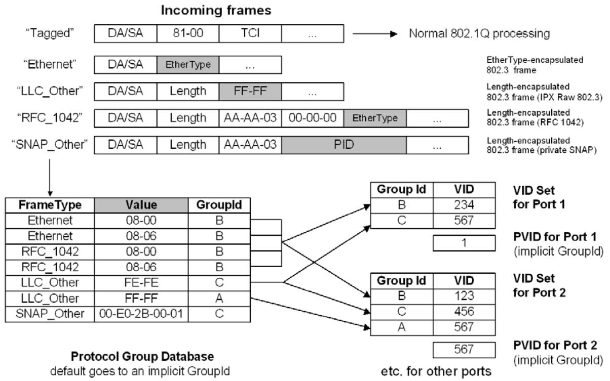
NOTE—The PID shown in this figure is a Protocol Identifier, as defined in 5.3 of IEEE Std 802. It is a 5-octet value, consisting of a 3-octet OUI or Company Identifier (CID) value followed by a 2-octet locally administered identifier.
Figure 6-4—Example of operation of Port-and-Protocol-based classification
The EtherType value is present if the detagged_frame_type parameter is present and has the value Ethernet or RFC_1042. Its value is the value of the IEEE 802.3 Length/Type Field present in the Detagged Frame. The value is determined as follows:
c) If the detagged_frame_type parameter is present and has the value Ethernet or RFC_1042, then this parameter is present and has the value of the IEEE 802.3 EtherType Field present in the Detagged Frame.
d) Else the parameter is not present.
The llc_saps parameter is present if the detagged_frame_type parameter is present and has the value LLC_Other. Its value is determined as follows:
e) If the detagged_frame_type parameter is present and has the value LLC_Other, then this parameter is present and its value is the pair of LLC ISO/IEC 8802-2 DSAP and SSAP address field values.
f) Else the parameter is not present.
NOTE 1—A frame that is encapsulated using values of hex FF/FF in the position where an LLC header is to be expected (as defined by ISO/IEC 8802-2) is known as a “Novell IPX Raw” encapsulation. Such frames do not conform to ISO/IEC 8802-2, in that they do not include some of the other required LLC fields. For the purposes of this standard, they are treated as LLC_Other, regardless of whether they are legal LLC frames.
NOTE 2—Bridges are not required, for the purposes of this standard, to completely verify whether the format of frames meets ISO/IEC 8802-2. They are required only to recognize the DSAP and SSAP fields of such frames.
The snap_pid parameter is present if the detagged_frame_type parameter is present and has the value SNAP_Other. Its value is determined as follows:
g) If the detagged_frame_type parameter is present and has the value SNAP_Other, then the parameter is present and its value is the contents of the 5 octets following the LLC header, i.e., the PID field.
h) Else the parameter is not present.
6.12.1 Protocol Templates
In a Bridge that supports Port-and-Protocol-based VLAN classification, a Protocol Template is a tuple that specifies a protocol to be identified in received frames. A Protocol Template has one of the following formats:
a) A value “Ethernet” and a 16-bit IEEE 802.3 EtherType Field value
b) A value "RFC_1042" and a 16-bit IEEE 802.3 EtherType Field value
c) A value "SNAP Other" and a 40-bit PID value
d) A value “LLC_Other” and a pair of ISO/IEC 8802-2 LSAP values: DSAP and SSAP
A Protocol Template matches a frame if
e) The frame's detagged_frame_type is Ethernet, the Protocol Template is of type Ethernet, and the frame's IEEE 802.3 EtherType Field is equal to the value of the IEEE 802.3 EtherType Field of the Protocol Template, or
f) The frame's detagged_frame_type is RFC_1042, the Protocol Template is of type RFC_1042 and the frame's IEEE 802.3 EtherType Field is equal to the IEEE 802.3 EtherType Field of the Protocol Template, or
g) The frame's detagged_frame_type is SNAP_Other, the Protocol Template is of type SNAP_Other, and the frame's snap_pid is equal to the PID of the Protocol Template, or
h) The frame's detagged_frame_type is LLC_Other, the Protocol Template is of type LLC_Other, and the frame's llc_saps matches the value of the DSAP and SSAP of the Protocol Template.
NOTE—If a port does not support Protocol Templates of the frame's detagged_frame_type, then no match will occur.
6.12.2 Protocol Group Identifiers
A Bridge that supports Port-and-Protocol-based VLAN classification shall support Protocol Group Identifiers.
A Protocol Group Identifier, shown as “Group Id” in Figure 6-4, designates a group of protocols that will be associated with one member of the VID Set of a Port. The association of protocols into groups is established by the contents of the Protocol Group Database, as described in 6.12.3. The identifier has scope only within a single Bridge.
An implicit Protocol Group Identifier is assigned to frames that match none of the entries in the Protocol Group Database. Therefore, every incoming frame can be assigned to a Protocol Group Identifier.
6.12.3 Protocol Group Database
A Bridge that supports Port-and-Protocol-based VLAN classification shall support a single Protocol Group Database. The Protocol Group Database groups together a set of one or more Protocols by assigning them the same Protocol Group Identifier (6.12.2). Each entry of the Protocol Group Database comprises the following:
a) A Protocol Template
b) A Protocol Group Identifier
The Protocol Group Database specifies a mapping from Protocol Templates to Protocol Group Identifiers. If two entries of the Protocol Group Database contain different Protocol Group Identifiers, then their Protocol Templates must also be different.
The entries of the Protocol Group Database may be configured by management. A Bridge that supports Port-and-Protocol-based VLAN classification shall support at least one of the Protocol Template formats.
An implicit Protocol Group Database entry exists that matches all frames. This entry is invoked for frames that do not match the template of any of the other entries. It references an implicit Protocol Group Identifier that selects the PVID on each port. In this way, it is ensured that all incoming frames are matched by a Protocol Group Identifier and, hence, are assigned to a VID.
NOTE—If there are no entries in the Protocol Group Database, then the frame relay behavior of this Bridge is identical to the frame relay behavior of a Bridge having the same number of Ports that supports only Port-based VLAN classification.
6.13 Support of the ISS for attachment to a PBN
This standard specifies both Customer Bridges (3.24) and Provider Bridges (3.169). The operation of Provider Bridges and PBNs is, by design, largely transparent to Customer Bridges and Customer Bridged Networks (CBNs). Figure 15-1 illustrates the relationship of the service provided by the MAC Sublayer functionality of Provider Bridges to that used by a Customer Bridge. This subclause enables a mechanism for a Customer Bridge attached to a PBN to request priority handling of frames.
The functions specified in this subclause provide the ISS to the MAC Relay Entity of a Customer Bridge by making use of the underlying ISS provided by the Media Access Method Convergence function as shown in Figure 6-5. These functions shall be one of the following:
a) When Service Access Priority Selection is disabled, the functions shall be null; i.e., each M_UNITDATA.request received from the provided ISS results in an M_UNITDATA.request with identical parameters presented to the underlying ISS, and each M_UNITDATA.indication received from the underlying ISS results in an M_UNITDATA.indication with identical parameters presented to the provided ISS.
b) When Service Access Priority Selection is enabled, the mac_service_data_unit in each M_UNITDATA.request is Priority-tagged with an S-TAG header when presented to the underlying ISS, and if an S-TAG header is present in the mac_service_data_unit parameter in an M_UNITDATA.indication received from the underlying ISS, the S-TAG header is removed before the M_UNITDATA.indication is presented to the provided ISS.
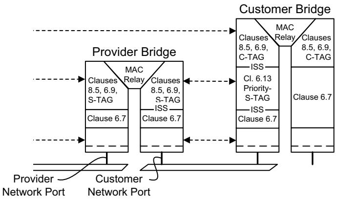
Figure 6-5—Service access priority selection
Specification of a null function allows a Customer Bridge without additional functionality to connect to a PBN.
Specification of the Service Access Priority Selection function allows the Customer Bridge Port to request priority handling of the frame from a Port-based service interface (15.3) to a PBN on the basis of the priority assigned within the CBN, while allowing for differences in cost and service level ascribed to individual values of priority within the service provider and customer networks.
6.13.1 Data requests
For each M_UNITDATA.request received from the provided ISS, an M_UNITDATA.request is presented to the underlying ISS with the following parameters:
The destination_address, source_address, and priority parameters are unchanged.
A tag header, formatted as necessary for the destination MAC type, is inserted as the initial octets of the mac_service_data_unit parameter. The Tag Protocol Identification is the Service VLAN Tag EtherType (9.5). The Tag Control Information (TCI) contains a null VID field, and PCP and DEI fields constructed as specified in 6.9.3 using a drop_eligible value of FALSE and a service_access_priority value derived from the priority parameter using Table 6-6.
Table 6-6—Service Access Priority
<table><tr><td>Received priority</td><td>Default service access priority</td><td>Range</td></tr><tr><td>0</td><td>0</td><td>0–7</td></tr><tr><td>1</td><td>1</td><td>0–7</td></tr><tr><td>2</td><td>2</td><td>0–7</td></tr><tr><td>3</td><td>3</td><td>0–7</td></tr><tr><td>4</td><td>4</td><td>0–7</td></tr><tr><td>5</td><td>5</td><td>0-7</td></tr><tr><td>6</td><td>6</td><td>0–7</td></tr><tr><td>7</td><td>7</td><td>0–7</td></tr></table>
Table 6-6 specifies default service_access_priority values for each of the eight possible values of the priority parameter in the M_UNITDATA.request received from the provided ISS. These default values shall be used as the initial values of the corresponding entries of the Service Access Priority Table for each Port supporting Service Access Priority Selection. The values in the table may be modified by management. If this capability is provided, the value of the table entries shall be independently settable for each Port and for each value of priority, and the Bridge shall have the capability to use the full range of the values in the parameter ranges specified in the table.
The frame_check_sequence parameter is either unspecified or contains a value modified from the received frame_check_sequence value taking into account the changes in the mac_service_data_unit parameter.
NOTE—The priority of the original service request made of the customer network can be carried transparently and unchanged across the PBN in the C-TAG.
6.13.2 Data indications
For each M_UNITDATA.indication received from the underlying ISS, an M_UNITDATA.request is presented to the supported ISS with the following parameters:
The destination_address and source_address parameters are unchanged.
If the initial octets of the mac_service_data_unit do not contain a tag header with the Service VLAN Tag EtherType value (9.5), then the mac_service_data_unit and frame_check_sequence parameters are unchanged; otherwise,
a) the mac_service_data_unit is detagged by removing the octets of the S-TAG header, and
b) the priority parameter is decoded from the PCP field (6.9.3),
c) the drop_eligible parameter is decoded from the Drop Eligible Indicator field (6.9.3), and
d) the frame_check_sequence parameter is either unspecified or contains a value modified from the received frame_check_sequence value taking into account the changes in the mac_service_data_unit parameter.
6.14 Support of the ISS within a system
A single system can comprise two or more instances of VLAN Bridge components connected by one or more of their Ports. If those Ports are not otherwise accessible, the ISS may be provided by means outside the scope of this specification. Figure 15-4 provides an example. Each instance of such an implementation of the ISS shall support the MAC status and Point-to-point parameters. An M_UNITDATA.request at one of the Ports connected to such an instance of the ISS shall result in M_UNITDATA.indications with identical parameters at all other Ports connected to that instance.
For convenience of management, such instances of ISS provision are assigned the LAN MAC Type 802.1. Management parameters common to MACs of this type are specified in Clause 12.
NOTE—The ISS can also be supported at Bridge Ports wholly contained within a system by any IEEE 802 LAN technology, subject to the system requirements of the particular media access method.
6.15 Support of the ISS by additional technologies
The ISS may be supported by other technologies that provide either an IEEE 802 MAC Service or an emulated IEEE 802 MAC Service. The technology is responsible for invoking an M_UNITDATA.indication with appropriate parameters (IEEE Std 802.1AC) for each received frame, and transmitting a frame in response to each M_UNITDATA.request. The mac_service_data_unit parameter in an M_UNITDATA.indication may include a tag header of a type recognized by the functions using the EISS (6.8). If multiplexing of multiple virtual instances of the MAC Service is provided, each virtual service must be
a) identified by the VID field in a tag header of a type recognized by the functions using the EISS, or
b) attached to separate instance of the ISS with no tag header in the mac_service_data_unit
(i.e., the only multiplexing recognized by the functions of the MAC Relay are those identified by a VID).
6.16 Filtering services in Bridged Networks
Bridges provide filtering services that support aspects of the maintenance of QoS—in particular, transit delay, priority, and throughput. In addition, these services provide a degree of administrative control over the propagation of particular MAC addresses in the network.
The services described are services in the most general sense; i.e., descriptions of functionality available to a MAC Service user or an administrator to control and access filtering capabilities. The descriptions make no assumptions about how the service might be realized. There are at least the following possibilities:
a) Use of existing protocols and mechanisms, defined in IEEE 802 standards and elsewhere.
b) Use of management functionality, either locally defined or via remote management protocols.
c) Other means, standardized or otherwise.
6.16.1 Purpose(s) of filtering service provision
Filtering services are provided for the purposes described in 6.16.1.1 and 6.16.1.2.
6.16.1.1 Administrative control
Filtering services provide administrative control over the use of particular source and destination addresses in designated parts of the network. Such control allows network managers and administrators to limit the extent of operation of network layer and other protocols that use individual and group MAC addresses by establishing administrative boundaries across which specific MAC addresses are not forwarded.
6.16.1.2 Throughput and end station load
Filtering services increase the overall throughput of the network, and reduce the load placed on end stations caused by the reception of frames that are destined for other end stations, by
a) Limiting frames destined for specific MAC addresses to parts of the network that, to a high probability, lie along a path between the source MAC address and the destination MAC address.
b) Reducing the extent of group addressed frames to those parts of the network that contain end stations that are legitimate recipients of that traffic.
c) In Virtual Bridged Networks, reducing the extent of frames on specific VLANs to those parts of the network that contain stations that are legitimate recipients of traffic on that VLAN.
NOTE—Some aspects of the filtering services described in this standard are dependent upon the active participation of end stations. Where such participation is not possible, those aspects of the filtering services will be unavailable.
6.16.2 Goals of filtering service provision
The filtering services provided can be used to
a) Allow the MAC Service provider to dynamically learn where the recipients of frames addressed to individual MAC addresses are located.
b) Allow end stations that are the potential recipients of MAC frames destined for group MAC addresses to dynamically indicate to the MAC Service provider which destination MAC address(es) they wish to receive.
c) Exercise administrative control over the extent of propagation of specific MAC addresses.
6.16.3 Users of filtering services
The filtering services provided are available to the following users:
a) Network management and administration, for the purposes of applying administrative control. Interactions between administrators of the network and the filtering service provider may be achieved by local means or by means of explicit management mechanisms.
b) End stations, for the purposes of controlling the destination addresses that they will receive. Interactions between end stations and the filtering service provider may be implicit, as is the case with the Learning Process (8.7), or by explicit use of filtering service primitives.
6.16.4 Basis of service
Filtering in Bridged Networks relies on the establishment of filtering rules, and subsequent filtering decisions, that are based on the value(s) contained in the Source MAC Address, Destination MAC Address, or VID fields in MAC frames.
NOTE—The filtering services defined by this standard use source address learning, destination address, and VID filtering.
6.16.5 Categories of service
Filtering services in Bridged Networks fall into the following categories:
a) Basic Filtering Services. These services are supported by the Forwarding Process (8.6) and by Static Filtering Entries (8.8.1), Static VLAN Registration Entries (8.8.2), Dynamic Filtering Entries (8.8.3), and Dynamic VLAN Registration Entries (8.8.5) in the FDB. The information contained in the Dynamic Filtering Entries is maintained through the operation of the Learning Process (8.7), while the information contained in the Dynamic VLAN Registration Entries is maintained through the operation of MVRP (11.2) and MIRP (Clause 39).
b) Extended Filtering Services. These services are supported by the Forwarding Process (8.6), and the Static Filtering Entries (8.8.1) and MAC Address Registration Entries (8.8.4) in the FDB. The information contained in the MAC Address Registration Entries is maintained through the operation of MMRP (10.9).
All Bridges shall support Basic Filtering Services and may support Extended Filtering Services.
6.16.6 Service configuration
In the absence of explicit information in the FDB, the behavior of the Forwarding Process with respect to the forwarding or filtering of frames destined for group MAC addresses depends upon the categories of service supported by the Bridge.
Basic Filtering Services support the filtering behavior required for regions of a Bridged Network in which potential recipients of multicast frames exist, but where either the recipients or the Bridges are unable to support the dynamic configuration of filtering information for those group MAC addresses, or the recipients have a requirement to receive all traffic destined for group MAC addresses.
Extended Filtering Services support the filtering behavior required for regions of a network in which potential recipients of multicast frames exist, and where both the potential recipients of frames and the Bridges are able to support dynamic configuration of filtering information for group MAC addresses. In order to integrate this extended filtering behavior with the needs of regions of the network that support only Basic Filtering Services, Bridges that support Extended Filtering Services can be statically and dynamically configured to modify their filtering behavior on a per-group MAC address basis, and also on the basis of the overall filtering service provided by each outbound Port with regard to multicast frames. The latter capability permits configuration of the Port's default forwarding or filtering behavior with regard to group MAC addresses for which no specific static or dynamic filtering information has been configured.
Service configuration provides the ability to configure the overall filtering for the following cases:
a) Bridges that only implement Basic Filtering Services.
b) Bridges that support Extended Filtering Services in a heterogeneous environment, where some equipment is unable to participate in Dynamic Multicast Filtering, or where some equipment (e.g., routers) has specific needs to see unfiltered traffic.
c) Bridges that support Extended Filtering Services in a homogeneous environment, where all equipment is able to participate in Dynamic Multicast Filtering.
6.16.7 Service definition for Extended Filtering Services
The Filtering Services are described by means of service primitives that define particular types of interaction between MAC Service users and the MAC Service provider across the MAC Service boundary. As these interactions are not defined between peer entities, they are described simply in terms of service requests sent from the MAC Service user to the MAC Service provider.
6.16.7.1 Dynamic registration and deregistration services
These services allow MAC Service users dynamic control over the set of destination MAC addresses that they will receive from the MAC Service provider, by
a) Registering/deregistering membership of specific Groups associated with those addresses.
b) Registering/deregistering individual MAC address information.
c) Registering/deregistering service requirements with regard to the overall forwarding/filtering behavior for Groups.
Provision of these services is achieved by means of MMRP and its associated procedures, as described in 10.9.
NOTE 1—These services can provide the MAC Service user with dynamic control over access to multicast data streams, for example, multiple video channels made available by a server using a different group MAC address for each channel. The ability to both register and deregister Group membership, coupled with the filtering action associated with the Group membership, limits the impact of such services on the bandwidth available in the network. These services can be used to control the reception of other categories of multicast traffic, for similar reasons.
REGISTER_MAC_ADDRESS (MAC_ADDRESS)
Indicates to the MAC Service provider that the MAC Service user wishes to receive frames containing the MAC address indicated in the MAC_ADDRESS parameter as the destination address. The MAC addresses that can be carried by this parameter do not include the following:
d) Any of the Reserved Addresses identified in Table 8-1, Table 8-2, or Table 8-3.
e) Any of the MRP Application addresses, as defined in Table 10-1.
DEREGISTER_MAC_ADDRESS (MAC_ADDRESS)
Indicates to the MAC Service provider that the MAC Service user no longer wishes to receive frames containing the MAC address indicated in the MAC_ADDRESS parameter as the destination address.
REGISTER_SERVICE_REQUIREMENT (REQUIREMENT_SPECIFICATION)
Indicates to the MAC Service provider that the MAC Service user has a requirement for any devices that support Extended Filtering Services to forward frames in the direction of the MAC Service user in accordance with the definition of the service requirement defined by the REQUIREMENT_SPECIFICATION parameter. The values that can be carried by this parameter are as follows:
f) Forward All Groups.
g) Forward Unregistered Groups.
DEREGISTER_SERVICE_REQUIREMENT (REQUIREMENT_SPECIFICATION)
Indicates to the MAC Service provider that the MAC Service user no longer has a requirement for any devices that support Extended Filtering Services to forward frames in the direction of the MAC Service user in accordance with the definition of the service requirement defined by the REQUIREMENT_SPECIFICATION parameter. The values that can be carried by this parameter are as follows:
h) Forward All Groups.
i) Forward Unregistered Groups.
The use of these services can result in the propagation of group MAC address and service requirement information across the spanning tree, affecting the contents of MAC Address Registration Entries (8.8.4) in Bridges and end stations, and thereby affecting the frame forwarding behavior of the Bridges and end stations with regard to multicast frames.
NOTE 2—If the EISS is supported, the Extended Filtering Service primitives issued by the MAC Service user should also include a VID parameter in order to identify the VLAN associated with the MAC_ADDRESS or REQUIREMENT_SPECIFICATION specified.
6.17 EISS Multiplex Entity
The EISS Multiplex Entity enables shims defined for the ISS to use the EISS. Figure 6-6 illustrates two EISS Multiplex Entities placed back-to-back.
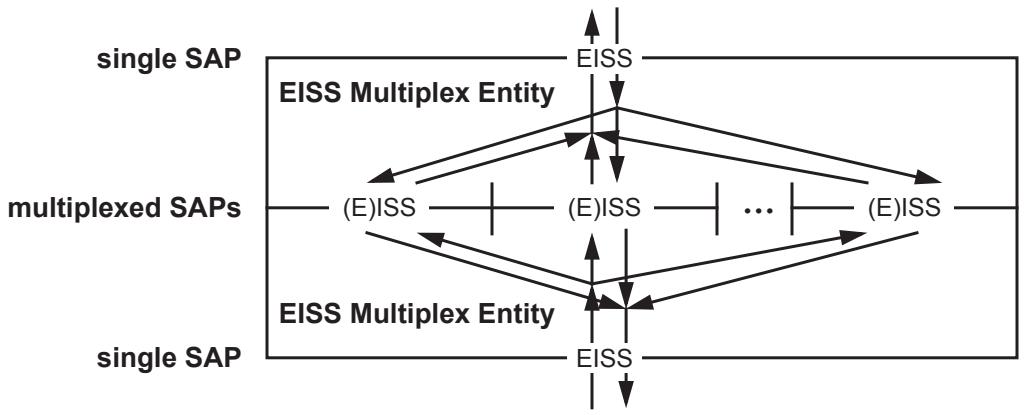
Figure 6-6—Two back-to-back EISS Multiplex Entities
An EISS Multiplex Entity has one EISS SAP, and a number of multiplexed SAPs, each either an ISS SAP or an EISS SAP. Each multiplexed ISS SAP is assigned to a single vlan_identifier value. Each multiplexed EISS SAP is assigned to one or more vlan_identifier values. Every vlan_identifier is assigned to some multiplexed SAP. Upon receiving a Request or Indication from its single EISS SAP, the EISS Multiplex Entity uses the vlan_identifier to select the corresponding one of its multiplexed SAPs to present the Request or Indication. Similarly, any Request or Indication received from a multiplexed SAP is presented to the single EISS SAP; the vlan_identifier parameter presented on the single EISS SAP is the one associated with the multiplexed ISS SAP, or the one obtained from the multiplexed EISS SAP.
Shims can be multiplexed in this fashion to separately serve multiple vlan_identifiers. Figure 22-1 illustrates CFM shims deployed in this manner.
The MAC_Operational status parameter (IEEE Std 802.1AC) presented to the uppermost EISS-SAP in Figure 6-6 is TRUE if and only if
a) The uppermost EISS-SAP's MAC_Enabled parameter is TRUE; and
b) At least one of its multiplexed SAPs' MAC_Operational status parameters is TRUE.
The MAC_Operational status parameter of each of the lower EISS Multiplex Entity's multiplexed SAPs in Figure 6-6 is computed separately and is TRUE if and only if
c) The lowermost EISS-SAP's MAC_Operational parameter is TRUE; and
d) That multiplexed SAP's MAC_Enabled parameter is TRUE.
6.18 Backbone Service Instance Multiplex Entity
The Backbone Service Instance Multiplex Entity allows shims defined for the ISS to be instantiated per backbone service instance at a SAP that supports multiple backbone service instances. Figure 6-7 illustrates two Backbone Service Instance Multiplex Entities placed back-to-back. A set of back-to-back Backbone Service Instance Multiplex Entities may be used at the ISS of a PIP or CBP to provide per Backbone Service Instance SAPs that support CFM shims at the Backbone Service Instance MD Level as shown in Figure 6-8 and the figures of 26.8.
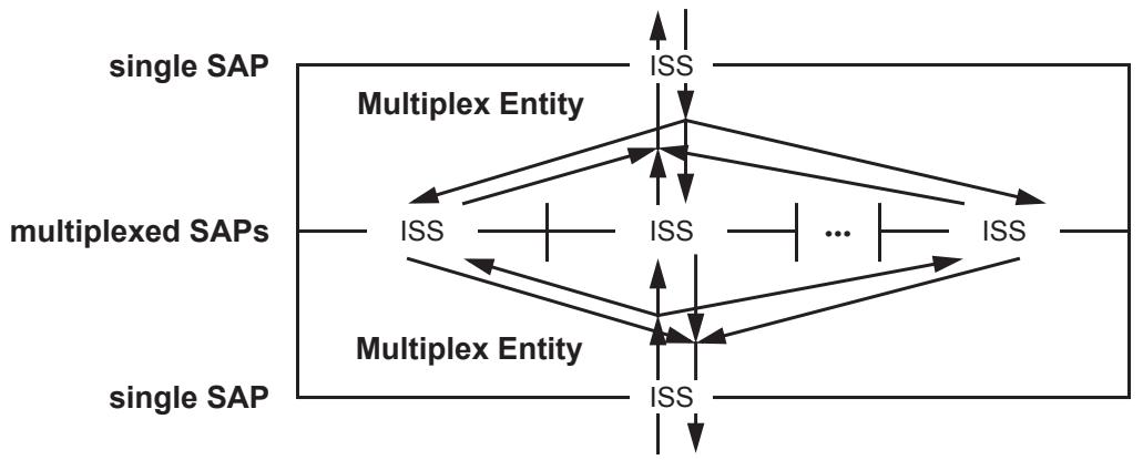
Figure 6-7—Two back-to-back Backbone Service Instance Multiplex Entities
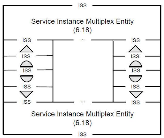
Figure 6-8—Backbone Service Instance Multiplex Entities with example CFM shims
NOTE 1—Figure 6-8 shows a representative placement of CFM shims between back-to-back Backbone Service Instance Multiplex Entities. This is not intended to imply any restriction that this is the only possible configuration of MEPs and MIPs.
A Backbone Service Instance Multiplex Entity has one ISS SAP that supports multiple backbone service instances, and a number of multiplexed ISS SAPs each supporting a single backbone service instance. Each multiplexed SAP has a single assigned I-SID value. Every I-SID value is assigned to a multiplexed SAP, and no I-SID value is assigned to more than one multiplexed SAP.
NOTE 2—There are implicitly $2^{24}$ multiplexed SAPs—one for each potential I-SID value. This does not require any implementation to support $2^{24}$ SAPs. The combined structure of back-to-back Backbone Service Instance Multiplex Entities is transparent to any frames with an I-SID value corresponding to a multiplexed SAP that does not have a protocol entity (e.g., CFM) instantiated at that SAP.
In the multiplexing direction, any Request or Indication received from a multiplexed SAP results in the generation of a corresponding Request or Indication to the single ISS SAP, with an I-TAG header added to the mac_service_data_unit as specified in 6.18.2. Similarly, in the demultiplexing direction any Request or Indication received from the single ISS SAP results in the generation of a corresponding Request or Indication at one of the multiplexed SAPs (determined by the I-SID contained in a I-TAG in the mac_service_data_unit), with the I-TAG removed from the mac_service_data_unit as specified in 6.18.1. When an I-TAG header with the UCA field containing a value of zero is removed, the C_DA and C_SA fields of the I-TAG remain in the mac_service_data_unit. In this case, a new EtherType field is prepended so the mac_service_data_unit still begins with a valid EtherType value. The Encapsulated Addresses EtherType value in Table 6-7 is allocated for this purpose.
Table 6-7—Encapsulated Addresses EtherType
<table><tr><td>Name</td><td>Value</td></tr><tr><td>IEEE 802.1Q Encapsulated Addresses EtherType</td><td>89-10</td></tr></table>
NOTE 3—This EtherType value is used only internally at the Backbone Service Multiplex Entity and does not appear in any frame on a LAN in the PBBN.
6.18.1 Demultiplexing direction
On receipt of an M_UNITDATA.request or M_UNITDATA.indication primitive from the single ISS SAP, the received frame shall be discarded if
a) The initial octets of the mac_service_data_unit do not contain a valid I-TAG; or
b) The Res2 field in the I-TAG is not zero.
Otherwise, an M_UNITDATA.request or M_UNITDATA.indication primitive is invoked at the multiplexed ISS SAP corresponding to the I-SID value in the I-TAG. The parameter values are determined as follows:
The connection_identifier parameter contains the same value as in the received primitive.
The destination_address and source_address parameters are determined as follows:
c) If the UCA bit is zero, the destination_address and source_address parameters contain the respective values in the received primitive;
d) Otherwise, the destination_address and source_address parameters contain the respective values in the C-DA and C-SA fields of the I-TAG.
The value of the drop_eligible and priority parameters are decoded from the I-DEI and the I-PCP fields of the I-TAG header in the mac_service_data_unit as described in 6.18.3.
The value of the mac_service_data_unit parameter is constructed from the value of the received mac_service_data_unit modified as follows:
e) If the UCA field in the I-TAG is zero, then the I-PCP, I-DEI, UCA, Res1, Res2, and I-SID fields of the I-TAG are removed and the Backbone Service Instance Tag EtherType value is replaced with the Encapsulated Addresses EtherType value (Table 6-7);
f) Otherwise, the entire I-TAG is removed.
The value of the frame_check_sequence parameter is either unspecified or derived from the received FCS information modified as necessary to take into account changes to the frame.
6.18.2 Multiplexing direction
On receipt of an M_UNITDATA.request or M_UNITDATA.indication primitive from any of the multiplexed ISS SAPs, an M_UNITDATA.request or M_UNITDATA.indication primitive is invoked at the single ISS SAP. The parameter values are determined as follows:
The source_address, priority, drop_eligible, and connection_identifier parameters contain the same value as in the received primitive.
The destination_address parameter is determined as follows:
a) If the destination_address in the received primitive is a group address and the UCA bit is set, then the destination_address parameter contains the Backbone Service Instance Group address constructed from the I-SID corresponding to the multiplexed ISS SAP at which the primitive was received;
b) Otherwise the destination_address parameter contains the same value as in the received primitive.
The value of the mac_service_data_unit parameter is equal to the value of the received mac_service_data_unit modified as follows:
c) If the initial two octets of the mac_service_data_unit match the Encapsulated Addresses EtherType value, then these octets are replaced with the Backbone Service Instance Tag EtherType value, and the I-PCP, I-DEI, UCA, Res1, Res2, and I-SID fields of an I-TAG are inserted following this EtherType value. The UCA, Res1 and Res2 fields all contain a value of zero. The I-SID field contains the value of the I-SID corresponding to the multiplexed ISS SAP at which the primitive was received. The values of the I-PCP and I-DEI fields are encoded from the drop_eligible and priority parameters as specified in 6.18.3.
d) If the initial two octets of the mac_service_data_unit do not match the Encapsulated Addresses EtherType value, then a complete I-TAG is prepended to the mac_service_data_unit. The UCA field contains a value of one. The Res1 and Res2 fields contain a value of zero. The C-DA and C-SA fields contain the destination_address and source_address from the received primitive, respectively. The I-SID field contains the value of the I-SID corresponding to the multiplexed ISS SAP at which the primitive was received. The values of the I-PCP and I-DEI fields are encoded from the drop_eligible and priority parameters as specified in 6.18.3.
The value of the frame_check_sequence parameter is either unspecified or derived from the received FCS information modified as necessary to take into account changes to the frame.
6.18.3 Priority Code Point encoding
The encoding (and decoding) of the I-PCP and I-DEI fields from (to) the priority and drop_eligible parameters is accomplished using a Priority Code Point Encoding Table (and Priority Code Point Decoding Table) as described in 6.9.3.
6.18.4 Status parameters
The MAC_Operational status parameter (IEEE Std 802.1AC) presented to the uppermost single ISS SAP in Figure 6-7 is TRUE if and only if
a) The uppermost single ISS SAP's MAC_Enabled parameter is TRUE; and
b) At least one of its multiplexed SAPs' MAC_Operational status parameters is TRUE.
The MAC_Operational status parameter of each of the multiplexed SAPs in Figure 6-7 is computed separately, and is TRUE if and only if
c) The lowermost single ISS SAP's MAC_Operational parameter is TRUE; and
d) That multiplexed SAP's MAC_Enabled parameter is TRUE.
6.19 TESI Multiplex Entity
The TESI Multiplex Entity allows shims defined for PBB-TE to be instantiated per TESI at a SAP that supports multiple TESIs. Figure 6-9 illustrates two TESI Multiplex Entities, placed back-to-back. A set of back-to-back TESI Multiplex Entities may be used at the multiplexed (E)ISS SAPs that are associated with ESP-VIDs on a CBP to provide per TESI SAPs that support CFM shims for PBB-TE MAs as shown in Figure 26-8.
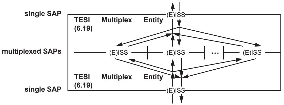
Figure 6-9—Two back-to-back Up and Down TESI Multiplex Entities
A TESI Multiplex Entity has one (E)ISS SAP that supports multiple TESIs, and a number of multiplexed (E)ISS SAPs each supporting a single TESI. Each multiplexed SAP has destination_address, source_address, and vlan_identifier combinations assigned by the TESI Multiplex Entity. Every destination_address, source_address, and vlan_identifier combination can be assigned to a multiplexed SAP, and no destination_address, source_address, and vlan_identifier combination is assigned to more than one multiplexed SAP.
Upon receiving a Request or Indication from its single (E)ISS SAP, the TESI Multiplex Entity uses the destination_address, source_address, and vlan_identifier to select the corresponding one of its multiplexed SAPs to present the Request or Indication. The Request or Indication presented at the multiplexed SAPs has the same parameters as the original Request or Indication at the Single SAP. Similarly, any Request or Indication received from a multiplexed SAP is transparently presented to the single (E)ISS SAP.
The MAC_Operational status parameter (6.8.2) presented to the uppermost single (E)ISS SAP in Figure 6-9 is TRUE if and only if
a) The uppermost single (E)ISS SAP's MAC_Enabled parameter is TRUE; and
b) At least one of its multiplexed SAPs' MAC_Operational status parameters is TRUE.
The MAC_Operational status parameter of each of the multiplexed SAPs in Figure 6-9 is computed separately, and is TRUE if and only if
c) The lowermost single (E)ISS SAP's MAC_Operational parameter is TRUE; and
d) That multiplexed SAP's MAC_Enabled parameter is TRUE.
The MAC_Operational parameter of the passive SAP on a PBB-TE MEP is set to FALSE when the PBB-TE MEP declares an errorCCMdefect (20.21.3) or an xconCCMdefect (20.23.3), setting the MAC_Operational parameter of the associated multiplexed SAP on the TESI Multiplex Entity to FALSE. The MAC_Operational parameter of the passive SAP on a PBB-TE MEP is set back to TRUE when both defects are cleared, setting back to TRUE the MAC_Operational parameter of the associated multiplexed SAP.
6.20 Support of the ISS with signaled priority
The functions specified in this subclause comprise a shim (3.201, IEEE Std 802.1AC) that uses an ISS SAP supported by a MAC entity (IEEE Std 802.1AC) to provide explicitly signaled priority information to an ISS SAP that supports a VLAN-unaware MAC Relay (Figure 6-10). Signaled priority information is derived from a VLAN tag header (9.3), if such header is present in the mac_service_data_unit. Any given instance of the ISS shall be supported by recognizing one but not both of the following VLAN Tag EtherTypes:
a) C-VLAN tag (C-TAG); or
b) S-VLAN tag (S-TAG).
The VLAN Tag EtherType is selected as specified in 9.5.
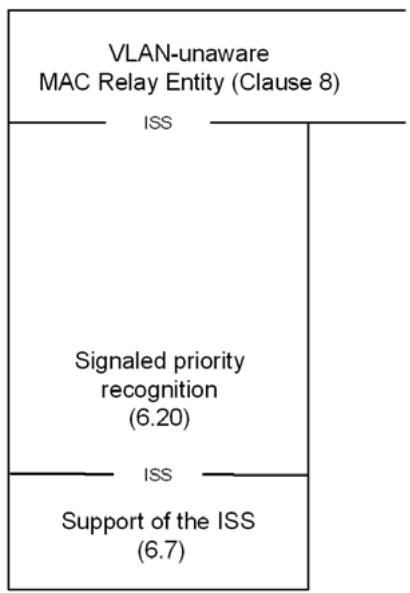
Figure 6-10—Supporting the ISS with signaled priority
6.20.1 Data indications
On receipt of an M_UNITDATA.indication primitive from the lower ISS SAP (Figure 6-10), an M_UNITDATA.indication primitive is invoked at the upper ISS SAP, with parameter values determined as follows:
The destination_address, source_address, connection_identifier, mac_service_data_unit, and frame_check_sequence parameters carry values equal to the corresponding parameters in the received data indication.
The value of the drop_eligible and priority parameters are determined as follows:
a) If the initial octets of the mac_service_data_unit contain a valid VLAN tag header (9.3) of the type used to support the EISS (9.5), the value of the drop_eligible parameter and the received priority value are decoded from the tag header as described in 6.9.3. Otherwise,
b) The received priority value and the drop_eligible parameter value are the values in the received data indication.
c) The value of the priority parameter is then regenerated from the received priority, as specified in 6.9.4.
6.20.2 Data requests
On receipt of an M_UNITDATA.request primitive from the upper ISS SAP (Figure 6-10), an M_UNITDATA.request primitive with identical parameter values is invoked at the lower ISS SAP.
6.21 Infrastructure Segment Multiplex Entity
The Infrastructure Segment Multiplex Entity allows shims defined for Segment Endpoint Ports (SEPs) and Segment Intermediate Ports (SIPs) to be instantiated per Infrastructure Segment at a SAP that supports multiple Infrastructure Segments. Figure 6-11 illustrates two Infrastructure Segment Multiplex Entities, placed back-to-back. A set of back-to-back Infrastructure Segment Multiplex Entities may be used at the multiplexed (E)ISS SAPs that are associated with SMP-VIDs on a PNP to provide per Infrastructure Segment SAPs that support CFM shims for Infrastructure Segment MAs as shown in Figure 26-10.
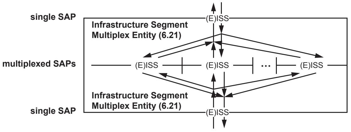
Figure 6-11—Two back-to-back Up and Down Infrastructure Segment Multiplex Entities
An Infrastructure Segment Multiplex Entity has one (E)ISS SAP that supports multiple Infrastructure Segment instances, and a number of multiplexed (E)ISS SAPs each supporting a single Infrastructure Segment instance. Each multiplexed SAP has destination_address, source_address, and vlan_identifier combinations assigned by the Infrastructure Segment Multiplex Entity. Every destination_address, source_address, and vlan_identifier combination can be assigned to a multiplexed SAP, and no destination_address, source_address, and vlan_identifier combination is assigned to more than one multiplexed SAP.
Upon receiving a Request or Indication from its single (E)ISS SAP, the Infrastructure Segment Multiplex Entity uses the destination_address, source_address, and vlan_identifier to select the corresponding one of its multiplexed SAPs to present the Request or Indication. The Request or Indication presented at the multiplexed SAPs has the same parameters as the original Request or Indication at the Single SAP. Similarly, any Request or Indication received from a multiplexed SAP is transparently presented to the single (E)ISS SAP.
The MAC_Operational status parameter (IEEE Std 802.1AC) presented to the uppermost single (E)ISS SAP in Figure 6-9 is TRUE if and only if
a) The uppermost single (E) ISS SAP's MAC Enabled parameter is TRUE; and
b) At least one of its multiplexed SAPs' MAC_Operational status parameters is TRUE.
The MAC_Operational status parameter of each of the multiplexed SAPs in Figure 6-9 is computed separately, and is TRUE if and only if
c) The lowermost single (E)ISS SAP's MAC Operational parameter is TRUE; and
d) That multiplexed SAP's MAC_Enabled parameter is TRUE.
The MAC_Operational parameter of the passive SAP on an Infrastructure Segment MEP is set to FALSE when the Infrastructure Segment MEP declares an errorCCMdefect (20.21.3) or an xconCCMdefect (20.23.3), setting the MAC_Operational parameter of the associated multiplexed SAP on the Infrastructure Segment Multiplex Entity to FALSE. The MAC_Operational parameter of the passive SAP on an Infrastructure Segment MEP is set back to TRUE when both defects are cleared, setting back to TRUE the MAC_Operational parameter of the associated multiplexed SAP.
7 Principles of Virtual Bridged Network operation
This clause establishes the principles and a model of Virtual Bridged Network operation. It defines the context necessary for
a) The operation of individual VLAN Bridges (Clause 8);
b) Their participation in the Spanning Tree Algorithm and Protocol (STP) (Clause 8 of IEEE Std 802.1D, 1998 Edition [B9]), Rapid Spanning Tree Algorithm and Protocol (RSTP) (Clause 13), Multiple Spanning Tree Algorithm and Protocol (MSTP) (Clause 13), and Shortest Path Bridging (SPB) protocols (Clause 27);
c) The management of individual Bridges (Clause 12); and
d) The management of VLAN Topology (Clause 11)
to support, preserve, and maintain the quality of the MAC Service as discussed in Clause 6.
7.1 Network overview
The operation of a Virtual Bridged Network, the Bridges, and the LANs that compose that network comprises
a) A physical topology comprising LANs, Bridges, and Bridge Ports. Each Bridge Port attaches a LAN to a Bridge and is capable of providing bidirectional connectivity for MAC user data frames. Each LAN is connected to every other LAN by a Bridge and zero or more other LANs and Bridges.
b) Calculation of one or more active topologies, each a loop-free subset of the physical topology.
c) Rules for the classification of MAC user data frames that allow each Bridge to allocate, directly or indirectly, each frame to one and only one active topology.
d) Management control of the connectivity provided for differently classified data frames by the selected active topology.
e) Implicit or explicit configuration of end station location information, identifying LANs with attached end stations that need to receive user data frames with a given destination address.
f) Communication of end station location information to allow Bridges to restrict user data frames to LANs in the path provided to their destination(s) by the chosen active topology.
These elements and their interrelationships are illustrated in Figure 7-1.
NOTE 1—The physical and active topologies can be represented as bi-partite graphs. Bridges and LANs are nodes in these graphs (including LANs that are point-to-point links) and the Bridge Ports are edges.
NOTE 2—This standard applies the notion of a physical topology to media access control methods, like wireless, where there is no tangible physical connection between a Bridge and an attached LAN. A Bridge Port models this association just as for wired connectivity.
NOTE 3—Each of the active topologies [see item b)] does not necessarily span the entire network, but does span all those Bridges and LANs between which data frame connectivity is desired for frames allocated to that active topology.
NOTE 4—The destination addressing information associated with a MAC user data frame includes the VLAN classification of the frame [see item d)].
NOTE 5—Implicit configuration [see item d)], or recognition, of end station location includes observation of the source address of the user data frame transmitted by that station. The user data frame communicates that location information [see item e)] along the portion of the chosen active topology leading to the frame's destination(s).
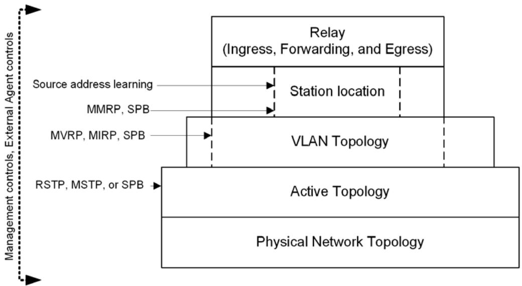
Figure 7-1—VLAN Bridging overview
7.2 Use of VLANs
VLANs and their VIDs provide a convenient and consistent network-wide reference for VLAN Bridges to
a) Identify rules for the classification of user data frames into VLANs;
b) Effectively extend the source and destination MAC addresses, by treating frames and addressing information for different VLANs independently;
c) Identify and select from different active topologies;
d) Identify configuration parameters that partition a physical network.
Taken together these capabilities allow VLAN Bridges to emulate a number of separately manageable, or virtual, Bridged Networks. A LAN that has been selected by network management to receive frames assigned to a given VLAN is said to form part of, belong to, or be a member of the VLAN. Similarly, end stations that are attached to those LANs and that can receive frames assigned to the VLAN are said to be attached to that VLAN.
NOTE—Separate control over the transmission and over the reception of frames to and from LANs and end stations is possible. To avoid ambiguity, VLAN membership is defined by reception.
Inclusion of the VID in VLAN-tagged frames guards against connectivity loops arising from differing classifications by different Bridges, and permits enhanced classification rules to be used by some Bridges, while others simply forward the previously classified frames.
The VLAN tag allows frames to carry priority information, even if the frame has not been classified as belonging to a particular VLAN.
7.3 Active topology
Bridges cooperate to calculate one or more loop-free and fully connected active topologies, i.e., spanning trees. The algorithms and protocols—RSTP (13.4), MSTP (13.5), SPB (Clause 27)—that support that calculation provide rapid recovery from network component failure (6.5.1) by using alternate physical connectivity, without requiring management intervention.
The Bridge's forwarding processes constrain the potential path for each user data frame to a single spanning tree. A Bridge that uses RSTP or STP allocates all frames to a single CST. An MST or SPT Region (13.8, 27.4.1) comprises the transitive closure of Bridges that use MSTP or SPB and that agree on the allocation of frames with a given VID to a given subtree within the region. That subtree can be an MSTI, a SPT, or the IST that is the logical continuation of the CST through the region. Interoperability between MST and SPT Bridges and SST Bridges, and between differently configured MST/SPT Bridges, is achieved by allocating all frames to the CST at region boundaries. Thus the spanning tree for a given frame can comprise subtrees of the CST together with an MSTI or SPT within each region. Frames with different VIDs can be assigned to the same or to different trees and subtrees within a region.
NOTE—In a stable network, the MSTP and SPB algorithms verify that each MST/SPT Region is fully connected internally. However, if the CST Root lies outside the region, the region can be partitioned temporarily as necessary to prevent external connectivity between Bridge Ports at the region boundary from creating a loop. A given region of the network can be an MST Region, an SPT Region, or both, but the protocol mechanisms that verify connectivity internal to the region require that regions do not overlap or subset other regions.
7.4 VLAN topology
Typically each of the VIDs for frames assigned to the CST, and to the IST or an MSTI within an MST Region, supports a different VLAN, and each VLAN is supported by only one VID and only one subtree within the region. However, frames for VLANs supported by SPB are assigned to the SPT rooted at the Bridge where they enter an SPT Region, and SPBV requires that each source Bridge for a given VLAN uses a unique SPVID. To provide interoperability with other regions and end systems that support a VLAN with a single VID, the VIDs for SPBV VLANs are translated at the SPT Region boundary (6.9, 27.12). SPBM uses a single VID for all the SPTs for a given VLAN.
NOTE 1—Support of a network comprising a single SPT Region with directly attached VLAN-unaware or priority tagging end stations does not require VID translation. This includes, for example, a PBN or PBBN where the edge of the network corresponds with the boundary of the SPT Region.
Within a given region, the SPTs that support any given shortest path VLAN provide full and symmetric connectivity (6.3). To allow frames in different VLANs to make use of equal cost shortest paths, multiple SPT Sets can be used, each providing full symmetric connectivity between all Bridges in the region.
Each VLAN may occupy the full extent of the active topology of its associated spanning tree(s) or a continuously connected subset of that active topology. The connected subset must be continuously connected; otherwise, the VLAN is split. The maximum extent of the connected subset may be bounded by management by explicitly excluding certain Bridge Ports from a VLAN's connectivity.
At any time the current extent of a VLAN can be further reduced from the maximum to include only those LANs that provide communication between attached devices, by the use of protocol that allows end stations to request and release services that use the VLAN. Such a protocol is specified in Clause 11. The dynamic determination of VLAN extent provides flexibility and bandwidth conservation, at the cost of network management complexity.
NOTE 2—Dynamic determination of VLAN extent is generally preferable to static configuration for bandwidth conservation, as the latter is error prone and can defeat potential alternate connectivity—requiring active management intervention to recover from network component failure.
NOTE 3—To accommodate end stations that do not participate in the MVRP specified in Clause 11, management controls associated with each Bridge Port allow the Port to identify the attached LAN as connecting end stations that require services using specified VLANs.
NOTE 4—Where a given VLAN is supported by multiple VIDs, as for SPB, management controls identify the VLAN by a Base VID (that used when frames are allocated to the CST). Use of this single VID reduces the configuration burden, particularly when Bridges are added to the SPT Region and further SPVIDs are allocated.
7.5 Locating end stations
Functioning as a distributed system, Bridges within the current extent of a VLAN can, through explicit and or implicit cooperation, locate those LANs where an attached end station or end stations are intended to receive frames addressed to a specified individual address or group address. Bridges can thus reduce traffic by confining frames to the LANs where their transmission is necessary.
NOTE 1—Individual Bridges do not determine the precise location of end stations but merely determine which of their Bridge Ports need to forward frames toward the destination(s). For the system of Bridges this is sufficient to restrict frames to the paths necessary to reach the destination LANs.
The Multiple MAC Registration Protocol (MMRP), specified in Clause 10, allows end stations to advertise their presence and their desire to join (or leave) a multicast group, or to register an individual MAC address, in the context of a VLAN. The protocol communicates this information to other Bridges, using the VLAN and its active topology.
NOTE 2—To accommodate end stations that do not participate in MMRP, management controls associated with each Bridge Port allow the port to identify the attached LAN as connecting end stations that are intended to receive specified group addresses. The continuous operation of MMRP and the propagation of location information through Bridges using the current active topology for the VLAN support multicast traffic reduction, while ensuring rapid restoration of multicast connectivity without management intervention if alternate connectivity is selected following network component failure.
Each end station implicitly advertises its attachment to an individual LAN and its individual MAC address whenever it transmits a frame. Bridges learn from the source address as they forward the frame along the active topology to its destination or destinations – or throughout the Bridged Network or VLAN if the location of the destination or destinations is unknown. The learned information is stored in the FDB (8.8) and used to filter frames on the basis of their destination addresses.
Address information learned from a frame with a given VID can be used to filter frames with other VIDs. For example, information learned from a frame with any of the VIDs that support SPB for a given VLAN (i.e., VIDs associated with the same Base VID) is used to filter frames with any of the VIDs for that VLAN. In some network configurations, it is also necessary to use address information learned in any one of a set of VLANs to filter frames with VIDs that identify any VLAN in the set (Shared VLAN Learning (SVL), Clause 3). In other configurations it is necessary or desirable not to share learned information between certain VLANs (Independent VLAN Learning (IVL), Clause 3) while in some cases it is immaterial whether address information is shared between VLANs. Annex F discusses the network configuration requirements, and some of the related interoperability issues.
Clause 15 and Clause 16 describe how the mapping of C-VLANs into S-VLANs is accomplished within PBNs and PBBNs. These networks provide additional mapping facilities to support hierarchies of VLANs allowing a provider a separate FDB from customers. The conformance definitions of 5.3 have been extended to support S-VLANs. Clause 25 and Clause 26 describe how the mapping of S-VLANs into backbone service instances is accomplished within PBBNs.
7.6 Ingress, forwarding, and egress rules
The relay function provided by each Bridge controls:
a) Classification of each received frame as belonging to one and only one VLAN, and discard or acceptance of the frame for further processing on the basis of that classification and the received frame format, which can be one of three possible types:
1) Untagged, and not explicitly identifying the frame as being associated with a particular VID;
2) Priority-tagged, i.e., including a tag header conveying explicit priority information but not identifying the frames as being associated with a specific VID;
3) VLAN-tagged, i.e., explicitly associating the frames with a particular VID. This aspect of relay implements the ingress rules.
b) Implementation of the decisions governing where each frame is to be forwarded as determined by the current extent of the VLAN topology (7.4), station location information (7.5), and the additional management controls specified in Clause 8. This aspect of relay implements the forwarding rules.
c) Queuing of frames for transmission through the selected Bridge Ports, management of the queued frames, selection of frames for transmission, and determination of the appropriate frame format type, VLAN-tagged or untagged. This aspect of relay implements the egress rules.
The structuring of the relay functionality into the implementation of ingress, forwarding, and egress rules constitutes a generic approach to the provision of VLAN functionality. All VLAN Bridges can correctly forward received frames that are already VLAN-tagged. These are classified as belonging to the VLAN identified by the VID in the tag header. All VLAN Bridges can also classify untagged and priority-tagged frames received on any given port as belonging to a specified VLAN. In addition to this default Port-based ingress classification, this standard specifies an optional Port-and-Protocol-based classification.
The classification of untagged and priority-tagged frames, and the addition or removal of tag headers, is performed in support of the EISS (6.9).
Frames that carry control information to determine the active topology and current extent of each VLAN, i.e., spanning tree or SPB and MVRP PDUs, and frames from other link constrained protocols, such as EAPOL and LLDP, are not forwarded. Permanently configured static entries in the FDB (8.2, 8.3, and 8.12) ensure that such frames are discarded by the Forwarding Process (8.6).
NOTE—MRPDUs destined for any MRP application are forwarded or filtered depending on whether the application concerned is supported by the Bridge, as specified in 8.1.2.
The forwarding rules specified for VLAN-tagged frames facilitate the interoperation of VLAN Bridges conformant to this standard with end stations that directly support attachment of MAC Service users to VLANs by transmitting VLAN-tagged frames, and with Bridges that are capable of additional proprietary ingress classification methods.
Frames transmitted on a given LAN by a VLAN Bridge for a given VLAN shall be either
d) All untagged; or
e) All VLAN-tagged with the same VID; or
f) All VLAN-tagged, each with an SPVID allocated to the Base VID for that VLAN.
8 Principles of Bridge operation
This clause
a) Explains the principal elements of the operation of Bridges, and the operation of Bridge components within systems, and lists the supporting functions.
b) Establishes a Bridge architecture that governs the provision of these functions.
c) Provides a model of Bridge operation in terms of processes and entities that support the functions.
d) Details the addressing requirements in a bridged network.
e) Specifies the addressing of entities in a Bridge.
8.1 Bridge operation
The principal elements of Bridge operation are
a) Relay and filtering of frames (8.1.1).
b) Maintenance of the information required to make frame filtering and relaying decisions (8.1.2).
c) Management of the above (Clause 12).
8.1.1 Relay
A Bridge relays individual MAC user data frames between the separate MACs of the individual LANs connected to its Ports. The functions that support relaying of frames and maintain the QoS are
a) Frame reception (8.5).
b) Discard on received frame in error (6.5.2).
c) Discard of frames that do not carry user data (IEEE Std 802.1AC).
d) Priority and drop eligibility decoding from a VLAN tag, if present, and regeneration of priority, if required (6.9).
e) Assignment of a VID to each received frame (6.9).
f) Ensure that each frame is confined to an active topology (8.6.1).
g) Frame discard to support management control over the active topology of each VLAN (6.9, 8.6.2, 8.6.4).
h) Frame discard following the application of filtering information (8.6.3).
i) Metering of frames, potentially marking as drop eligible or discarding frames exceeding bandwidth limits (8.6.5).
j) Forwarding of received frames to other Bridge Ports (8.6.6).
k) Selection of traffic class and queuing of frames by traffic class (8.6.6).
1) Frame discard to ensure that a maximum Bridge transit delay is not exceeded (6.5.6, 8.6.7).
m) Preferential discard of drop eligible frames to preserve QoS for other frames (8.6.7).
n) Selection of queued frames for transmission (8.6.8).
o) Mapping of SDUs and FCS recalculation, if required (6.5.7).
p) Frame discard on transmittable SDU size exceeded (6.5.8).
q) Selection of outbound access priority (6.5.9).
r) Frame transmission (8.5).
A VLAN-unaware MAC Relay Entity is supported by the ISS, and not the EISS, and correspondingly the functions that support relaying of frames in a MAC Bridge cannot make use of any parameters explicit to EISS, like the VIDs. This means in particular that for a MAC Bridge, item e) in the list above is not supported, items d) and g) would be supported in the form of
s) Regeneration of priority, if required (6.9.4);
t) Frame discard to support management control over the physical topology of the network;
and, every other item on the list is supported but without making any use of, or qualification upon, VIDs.
Figure 8-1 gives an example of the physical topology of a Bridged Network.
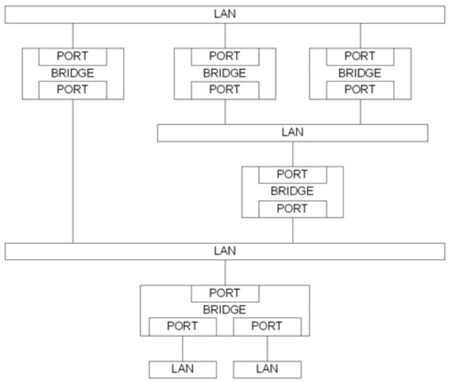
Figure 8-1—A Bridged Network
8.1.2 Filtering and relaying information
A Bridge maintains filtering and relaying information for the following purposes:
a) Duplicate frame prevention: to maintain a loop-free active topology for every frame;
b) Traffic segregation: to separate communication by different sets of network users;
c) Traffic reduction: to confine frames to the path(s) between their source and destination(s);
d) Traffic expediting: to classify frames in order to expedite time-critical traffic;
e) Frame format conversion: to tag or untag as appropriate for the destination LAN and stations.
8.1.3 Duplicate frame prevention
A Bridge filters frames, i.e., does not relay frames received by a Bridge Port to other Bridge Port on that Bridge, in order to prevent the duplication of frames (6.5.4). The functions that support the use and maintenance of information for this purpose are
a) Configuration and calculation of one or more spanning tree active topologies.
b) In MST Bridges, explicit configuration to assign VIDs to MSTIs (8.9).
c) In SPT Bridges: explicit or default selection of shortest path, CIST, or MSTI support for specified VLANs; and automatic assignment of VIDs to SPTs for shortest path VLANs.
8.1.4 Traffic segregation
A VLAN Bridge can filter frames to confine them to LANs that belong to the VLAN to which they are assigned and, thus, define the VLAN's maximum extent (7.4). The functions that support the use and maintenance of information for this purpose are
a) Configuration of a PVID for each Port, to associate a VID with untagged and priority-tagged received frames (6.9.1), and parameters for Protocol VLAN Classification (6.12) if implemented;
b) Configuration of Static VLAN Registration Entries (8.8.2);
c) Configuration of the Enable Ingress Filtering parameter to enable or disable application of Static VLAN Registration Entries to received frames.
A VLAN Bridge can filter frames to partially partition a Virtual Bridged Network. Frames assigned to any given VID and addressed to specific end stations or groups of end stations can be excluded from relay to certain Bridge Ports. The functions that support the use and maintenance of information for this purpose are
d) Permanent configuration of Reserved Addresses (Table 8-1, Table 8-2, and Table 8-3);
e) Configuration of Static Filtering Entries (8.8.1) and MAC Address Registration Entries (8.8.4).
NOTE—The use of VLANs is generally less error prone and is preferred to filtering using destination addresses if a Bridged Network is to be partitioned for reasons of scale, efficiency, management, or security. Destination address filtering is the only mechanism available to MAC Bridges.
8.1.5 Traffic reduction
A Bridge can filter frames so that LANs not attaching to or forming part of the path between the source and the potential destination(s) of any given communication do not have to support the transmission of related frames, potentially improving the quality of the MAC Service for other communications. The functions that support the use and maintenance of information for this purpose are
a) Automatic learning of dynamic filtering information for unicast destination addresses through observation of source addresses of frames;
b) Ageing out or flushing of dynamic filtering information that has been learned to support the movement of end stations and changes in active topology;
c) Automatic configuration of MAC Address Registration Entries by means of MMRP exchanges;
d) Explicit configuration of the management controls associated with the operation of MMRP by means of MAC Address Registration Entries.
A VLAN Bridge can also filter frames to confine them to LANs either that have end stations attached to their assigned VLAN or that connect those LANs and, thus, define the current practical extent of the VLAN (7.5).
e) Automatic inclusion and removal of Bridge Ports in the VLAN, through configuration of Dynamic VLAN Registration Entries by means of MVRP (8.8.5 and 11.2) or MIRP (Clause 39);
f) Explicit configuration of management controls associated with the operation of MVRP and MIRP by means of Static VLAN Registration Entries (8.8.2 and 11.2);
Items e) and f) are only supported by VLAN Bridges, while all other items in the list above are supported by every Bridge.
8.1.6 Traffic expediting
A Bridge classifies frames into traffic classes in order to expedite transmission of frames generated by critical or time-sensitive services. The function that supports the use and maintenance of information for this purpose is
a) Explicit configuration of traffic class information associated with the Ports of the Bridge.
8.1.7 Conversion of frame formats
A VLAN Bridge adds and removes tag headers (9.3) from frames and performs the associated frame translations that may be required. The function that supports the use and maintenance of information for this purpose is
a) Explicit configuration of tagging requirements on transmission for each Port (8.8.2, 6.9.2).
NOTE—As all incoming frames, including priority-tagged frames, are classified as belonging to a VLAN, the transmitting Port transmits VLAN-tagged frames or untagged frames. Hence, a station sending a priority-tagged frame via a Bridge will receive a response that is either VLAN-tagged or untagged, as described in 8.5.
8.2 Bridge architecture
A Bridge comprises at least one Bridge component. A Bridge component comprises
a) A MAC Relay Entity that interconnects the Bridge's Ports;
b) At least two Ports;
c) Higher layer entities, including at least a Spanning Tree Protocol Entity.
The VLAN Bridge architecture is illustrated in Figure 8-2. The MAC Relay Entity handles the media access method-independent functions of relaying frames among Bridge Ports, filtering frames, and learning filtering information. It uses the EISS (6.8, 6.9) provided by each Bridge Port.
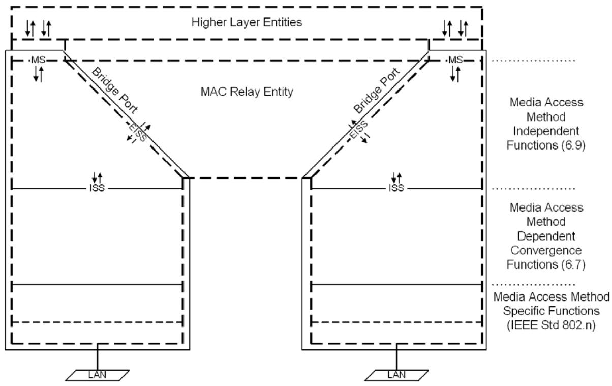
NOTE—The notation “IEEE Std 802.n” in this figure indicates that the specifications for these functions can be found in the relevant standard for the media access method concerned; for example, n would be 3 (IEEE Std 802.3) in the case of Ethernet.
Figure 8-2—VLAN Bridge architecture
The MAC Bridge architecture is illustrated in Figure 8-3. The main difference with the VLAN Bridge architecture is that it does not use the EISS and the VLAN-unaware MAC relay entity is supported by the ISS.
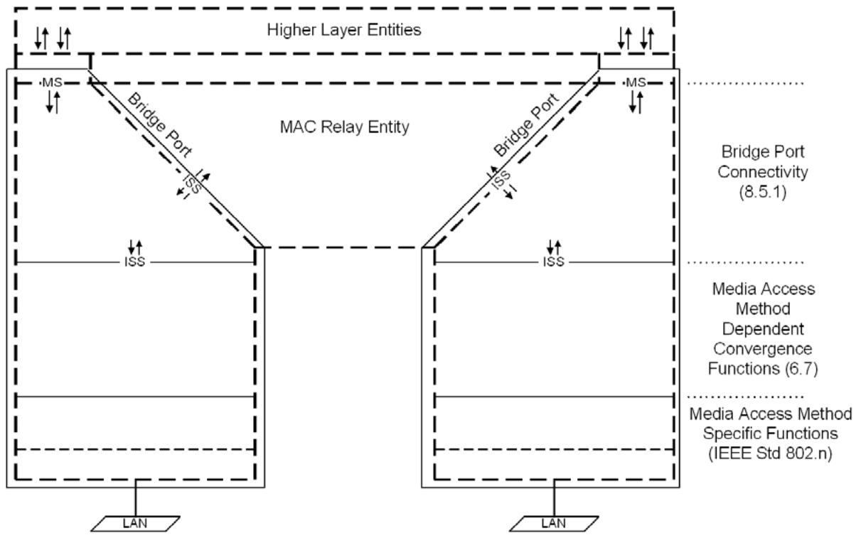
Figure 8-3—MAC Bridge architecture
Each Bridge Port also functions as an end station and shall provide the MAC Service to an LLC Entity that operates LLC Type 1 procedures to support protocol identification, multiplexing, and demultiplexing, for PDU transmission and reception by the Spanning Tree Protocol Entity and other higher layer entities. Other types of LLC procedures can also be supported for use by other protocols. The Bridge Port provides additional MSAPs if those are explicitly required by the specifications of the attached higher layer entities. Each instance of the MAC Service is provided to a distinct LLC Entity that supports protocol identification, multiplexing, and demultiplexing, for PDU transmission and reception by one or more higher layer entities.
NOTE—For simplicity of specification, this standard refers to a single LLC Entity that can provide both the procedures specified by ISO/IEC 8802-2 and EtherType protocol discrimination in the cases where the media access method for the attached LAN supports the latter.
If the Bridge Port can be directly attached to an IEEE 802 LAN, an instance of the MAC for that LAN type is permanently associated with the Port, handles the media access method-specific functions (MAC protocol and procedures), and provides an instance of the ISS as specified in IEEE Std 802.1AC to support frame transmission and reception by the other processes and entities that compose the Port.
Figure 8-2 illustrates a VLAN Bridge, and Figure 8-3 illustrates a MAC Bridge, with two Ports, each directly connected to a LAN.
8.3 Model of operation
The model of operation is simply a basis for describing the functionality of the Bridge. It is in no way intended to constrain real implementations of a Bridge; these may adopt any internal model of operation compatible with the externally visible behavior that this standard specifies. Conformance of equipment to this standard is purely in respect of observable protocol.
The processes and entities that model the operation of a Bridge Port include
a) A Bridge Port Transmit and Receive Process (8.5) that
1) Receives and transmits frames from and to the attached LAN (8.5, 6.8, 6.9, IEEE Std 802.1AC);
2) Can filter received frames if the VLAN tag is absent, or present, or conveys a null VID;
3) Classifies received frames into VLANs, assigning each a VID value;
4) Determines the format, VLAN-tagged or untagged, of transmitted frames;
5) Delivers and accepts frames to and from the MAC Relay Entity and LLC Entities;
b) The LLC Entity or Entities that support Higher Layer Entities such as
1) Spanning Tree Protocol;
2) Multiple Registration Protocol (MRP);
3) Bridge Management;
4) Linktrace response.
c) Zero or more CFM entities, each of which can be one of the following:
1) An MA Endpoint (MEP);
2) An MA Intermediate Point (MIP); or
3) A Linktrace Output Multiplexer (LOM).
As Bridge Ports on MAC Bridges provide only the ISS, items a2), a3), and a4) in the list above are not supported by MAC Bridges.
d) The Forwarding Process (8.6) that
1) Enforces loop-free active topologies for all frames (8.1.3, 8.4, 8.6.1);
2) Filters frames using their VID and destination MAC addresses (8.1.4, 8.6.2, 8.6.3, 8.6.4);
3) Optionally, classifies and meters received frames that are to be relayed to other Bridge Ports (8.6.5);
4) Forwards received frames that are to be relayed to other Bridge Ports (8.6.6, 8.6.7, 8.6.8);
e) The Learning Process (8.7) that observes the source addresses of frames received on each Port, and updates the FDB (8.1.5, 8.4);
f) The FDB (8.8) that holds filtering information and supports queries by the Forwarding Process about whether frames with given values of VID and destination MAC address field can be forwarded to a given Port.
NOTE 1—The processes and entities that model the operation of the VLAN-unaware MAC Relays on MAC Bridges are the same as the ones described above but excluding any use or qualification based on VID values.
Figure 8-4 illustrates a single instance of frame relay between the Ports of a Bridge with two Ports.
NOTE 2—In Figure 8-4, Figure 8-5, Figure 8-6, and Figure 8-7, the EISS is used by the VLAN-aware MAC Relay entities and the ISS is used by the VLAN-unaware MAC Relay entities.
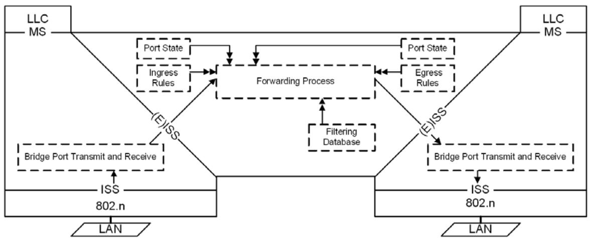
Figure 8-4—Relaying MAC frames
Figure 8-5 illustrates the inclusion of information carried by a single frame, received on one of the Ports of a Bridge with two Ports, in the FDB.
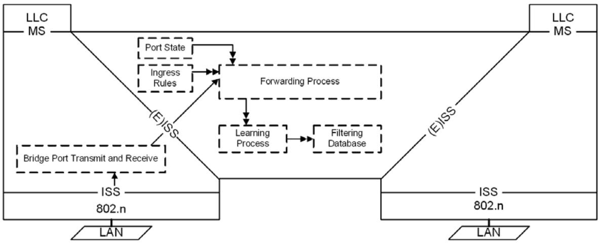
Figure 8-5—Observation of network traffic
Figure 8-6 illustrates the operation of the Spanning Tree Protocol Entity.
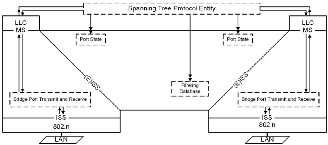
Figure 8-6—Operation of Spanning Tree Protocol Entity
Figure 8-7 illustrates the operation of the MRP Entity (8.11).
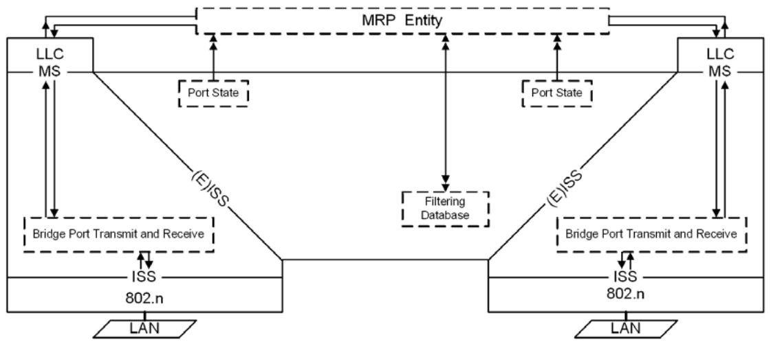
Figure 8-7—Operation of MRP
Higher Layer Entities that require only one point of attachment for the Bridge as a whole may attach to an LLC Entity that uses an instance of the MAC Service provided by a Management Port. A Management Port does not use an instance of the ISS to attach to a network but uses the Bridge Port Transmit and Receive Process and the MAC Relay Entity to provide connectivity to other Bridge Ports and the attached LANs.
NOTE 3—Management port functionality may also be provided by an end station connected to an IEEE 802 LAN that is wholly contained within the system that incorporates the Bridge. The absence of external connectivity to the LAN means that the management port is always forwarding.
Figure 8-8 illustrates the reception and transmission by an entity attached to a Management Port.
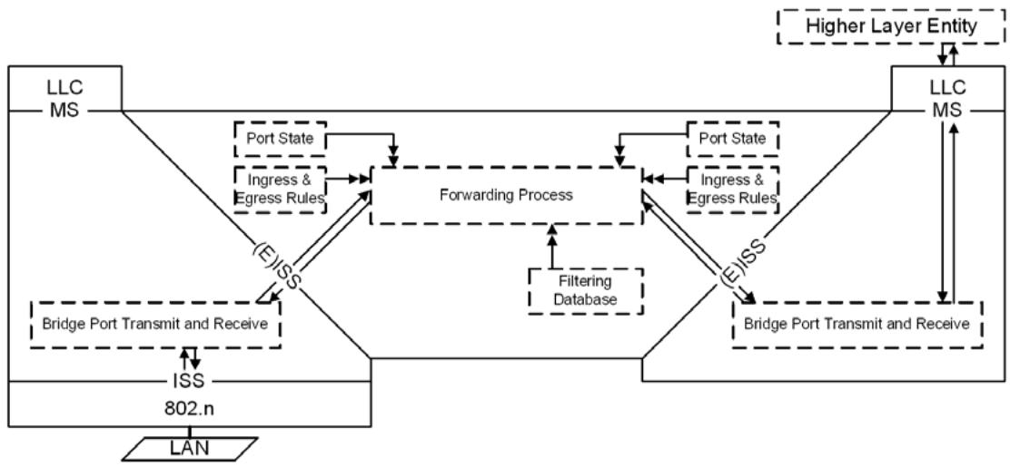
Figure 8-8—Management Port transmission and reception
Figure 8-8 illustrates the operation of the IPS Control entity. The IPS Control entity functions as an intermediary between the Bridge Management entity and the FDB for operations related to TESIs associated with an IPG. Infrastructure Segment MEPs associated with an IPG communicate the operational state of the associated Infrastructure Segment to the IPS control entity (26.11.3).
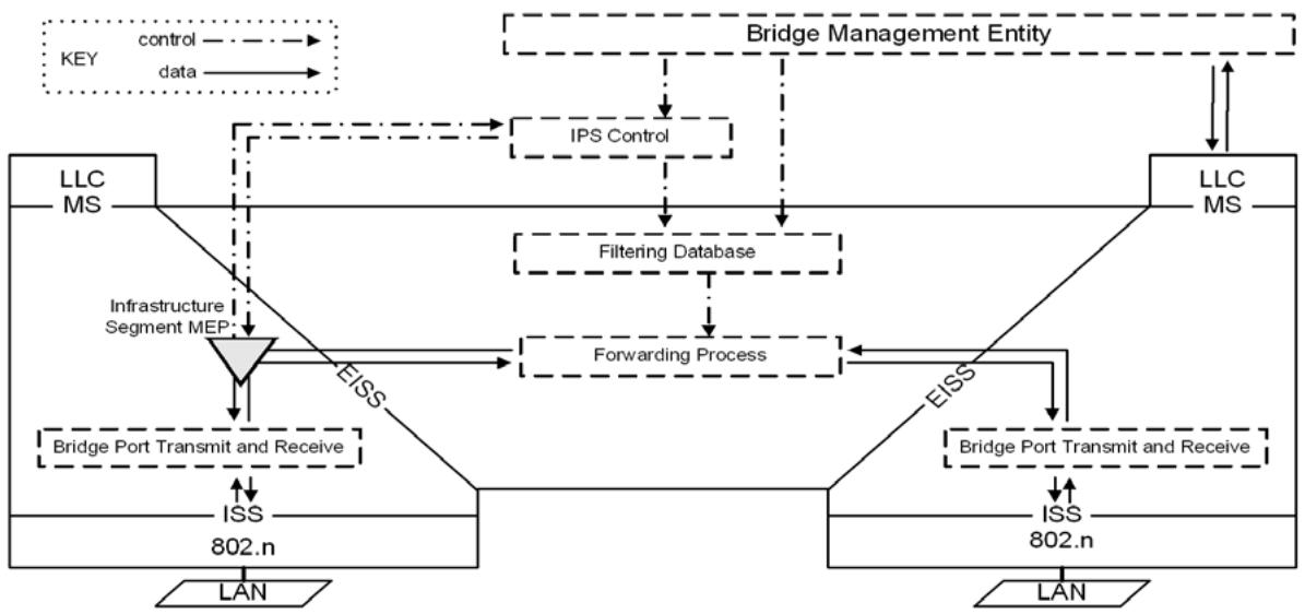
Figure 8-8—Infrastructure Segment MEP placement in a PNP
8.4 Active topologies, learning, and forwarding
An active topology is the connectivity provided, for frames with a specified set of VID, destination address, and source address values, by interconnecting the LANs and Bridges in a bridged network with forwarding Bridge Ports.
The distributed spanning tree algorithms and protocols, i.e., RSTP (Clause 13), MSTP (Clause 13), and ISIS-SPB (Clause 27), construct one or more active topologies, each simply and fully connected for frames being associated with any given VLAN and transmitted from any end station to any other. The forwarding and learning performed by each Bridge Port for each spanning tree is dynamically managed by RSTP, MSTP, or ISIS-SPB to prevent temporary loops and reduce excessive traffic in the network while minimizing denial of service following any change in the physical topology of the network.
PBB-TE enables construction of active topologies by the external agent that is responsible for setting up Ethernet Switched Paths (ESPs).
Any port that is not enabled, i.e., has MAC_Operational (IEEE Std 802.1AC) False or has been excluded from the active topology by management setting of the Administrative Bridge Port State to Disabled, has both forwarding and learning disabled for all spanning trees and ESPs.
If the Bridge Port is enabled, PBB-TE disables learning and enables forwarding for all frames allocated to each ESP-VID. An external agent manages the FDB to control the forwarding of frames with particular values of ESP-VID and destination MAC address.
The term Port State summarizes per-tree combinations of forwarding and learning, and any additional per-tree variables used by a given spanning tree protocol to enforce the active topologies it has calculated, and is used by RSTP and MSTP as follows. Any port that has learning and forwarding disabled is assigned the Port
State Discarding. A Port that has learning enabled but forwarding disabled has the Port State Learning, and a Port that both learns and forwards frames has the Port State Forwarding. However, the RSTP and MSTP state machines (Clause 13) do not control the Port State directly but use independent forwarding and learning variables for each tree.
ISIS-SPB controls both forwarding and learning variables for each SPT and Bridge Port directly when used to support Shortest Path Bridging VID (SPBV, Clause 27) just like RSTP and MSTP. ISIS-SPB disables learning and sets forwarding to TRUE when supporting Shortest Path Bridging MAC (SPBM, Clause 27).
RSTP constructs a single spanning tree, the CST, and maintains a single Port State for each Bridge Port. SST Bridges allocate all frames to that single spanning tree irrespective of their VLAN classification or source and destination MAC addresses.
MSTP constructs multiple spanning trees, the CIST and additional MSTIs, and maintains a Port State for each spanning tree for each Port. An MST Bridge allocates all frames classified as belonging to a given VLAN to the CIST or to one of the MSTIs using the MST Configuration Table. An MSTID of 0 identifies the CIST. A reserved MSTID value (TE-MSTID) is used to identify VIDs for use by PBB-TE with ESPs. Further MSTID values are used to identify the use of SPBV or SPBM. A single VID is used to identify frames assigned to any given VLAN that is supported by the CIST or an MSTI. That VID is used by the Forwarding Process (8.6) to identify the spanning tree for the relayed frame, and thus identifies the applicable Port State.
ISIS-SPB constructs symmetric (Clause 3) SPTs rooted at each Bridge within an SPT Region, and maintains independent forwarding and learning variables for each SPT for each Bridge Port.
Each frame classified as belonging to a VLAN supported by SPBV, is allocated to an SPT rooted at the Bridge that first relays the frame into the Region. If a C-VLAN, S-VLAN, or B-VLAN is supported by SPBV (Clause 27) the frame is assigned a Shortest Path VLAN Identifier (SPVID) that is used by the Forwarding Process (8.6) to identify both the VLAN and the SPT, and thus identifies the applicable learning and forwarding values.
If a B-VLAN is supported by SPBM, (Clause 27) the frame is assigned a B-VID value that identifies the frame as subject to SPBM and identifies the B-VLAN and the SPT Set (Clause 3). The SPT is identified (from among those in that set) by the source address of the frame (B-SA), which identifies the SPT root. When ISIS-SPB sets forwarding True for that SPT, a Dynamic Filtering Entry for that B-VID, source address tuple is included in the FDB so that it passes the active topology enforcement check (8.6.1). If a B-VLAN is supported by SPBM, learning is disabled for all frames for that B-VID.
Figure 8-6 illustrates the operation of the Spanning Tree Protocol Entity, which operates the spanning tree algorithm and its related protocols, and its modification of Port state information as part of determining the active topology of the network.
Figure 8-4 illustrates the Forwarding Process's use of the Port State: first, for a Port receiving a frame, to determine whether the received frame is to be relayed through any other Ports; and second, for another Port in order to determine whether the relayed frame is to be forwarded through that particular Port.
Figure 8-5 illustrates the use of the Port state information for a Port receiving a frame, in order to determine whether the station location information is to be incorporated in the FDB.
8.5 Bridge Port Transmit and Receive
The Bridge Port Transmit and Receive process supports the attachment of the Bridge Port to a network. It comprises the following functions:
a) In a VLAN Bridge component, mapping between the EISS (6.8) provided to the MAC Relay Entity, and the ISS (IEEE Std 802.1AC), adding, recognizing, interpreting, and removing VLAN tags as specified in 6.9 and illustrated in Figure 8-9;
b) In a MAC Bridge component, an optional shim (IEEE Std 802.1AC) that uses and provides the ISS (IEEE Std 802.1AC), recognizing and interpreting VLAN tags as specified in 6.20 and illustrated in Figure 8-10.
c) Connectivity, as specified in 8.5.1 (for non-TPMR Bridges) or 8.5.2 (for TPMRs), between the following ISS access points:
1) That provided by the MAC Entity for the LAN attached to the Port, as specified in IEEE Std 802.1AC;
2) That supporting the MAC Relay Entity; and
3) One or more that support Higher Layer Entities attached to the Port (8.5.3).
A single Port for a Bridge, known as the Management Port, may support Higher Layer Entities without providing a point of attachment to a LAN (see Figure 8-8).
8.5.1 Bridge Port connectivity
Each M_UNITDATA.indication provided by the ISS access point for an attached LAN [(1) in Figure 8-9] shall result in a corresponding M_UNITDATA.indication with identical parameters at each of the access points supporting the MAC Relay and Higher Layer Entities [(2), (3a) and (3b)]. Each M_UNITDATA.request from the ISS access point supporting the MAC Relay Entity shall result in a corresponding M_UNITDATA.indication with identical parameters at each of the access points for the Higher Layer Entities [(3a) and (3b)], and a corresponding M_UNITDATA.request with identical parameters at the access point for the LAN [(1)]. Each M_UNITDATA.request from an ISS access point supporting a Higher Layer Entity shall result in a corresponding M_UNITDATA.indication with identical parameters at the access points for the MAC Relay Entity, and at other access points for Higher Layer Entities, and a corresponding M_UNITDATA.request with identical parameters at the access point for the LAN.
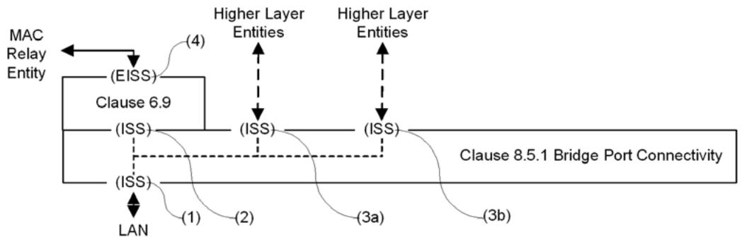
Figure 8-9—Bridge Port Transmit and Receive
NOTE—Figure 8-9 shows the relative position of the Bridge Port Transmit and Receive process and the VLAN tagging function (6.9) for a Customer Bridge or Provider Bridge that does not support CFM. For the relative positioning of these functions in a Bridge supporting CFM, see Figure 22-4. For the relative positioning of these functions in a BEB, see Figure 26-2.
The MAC_Enabled, MAC_Operational, and operPointToPointMAC status parameters for the ISS access point for the MAC Relay Entity and Higher Layer Entities [(2), (3a), and (3b) in Figure 8-9] shall take the same value as that for the LAN (1) if that is present, and shall be True otherwise (i.e., if the Port is a Management Port).
The consequence of the above connectivity is that frames relayed to a Bridge Port are both submitted to that Port's MAC Service users and transmitted on the attached LAN (see 8.13.9).
8.5.2 TPMR Port connectivity
Each M_UNITDATA.indication provided by the ISS access point for an attached LAN [(1) in Figure 8-10] shall result in a corresponding M_UNITDATA.indication with identical parameters at each of the access points supporting the MAC Relay and Higher Layer Entities[(2), (3a), and (3b)].
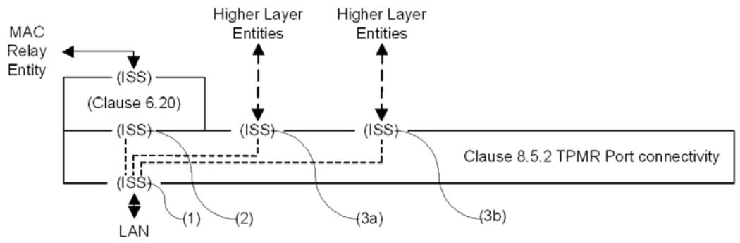
Figure 8-10—TPMR Port Transmit and Receive
Each M_UNITDATA.request from the ISS access point supporting the MAC Relay Entity (2) or a Higher Layer Entity [(3a) or (3b)] shall result in a corresponding M_UNITDATA.request with identical parameters at the access point for the LAN (1).
The MAC_Enabled, MAC_Operational, and operPointToPointMAC status parameters for the ISS access point for the MAC Relay Entity and Higher Layer Entities [(2), (3a), and (3b) in Figure 8-10] shall take the same value as for the LAN (1).
NOTE—These connectivity rules allow a higher layer entity to “listen” on both TPMR Ports to be able to determine the LAN on which a particular frame was received, and ensure that any frames sent by a higher layer entity are propagated only on the LAN associated with the Port on which the frame is transmitted. This differs from the propagation rules for other Bridges, where frames transmitted by a higher layer entity are also submitted to the forwarding process, and frames transmitted by the Forwarding Process on a given Port are received by any higher layer entity associated with that Port.
8.5.3 Support of Higher Layer Entities
The MAC Service is provided to a Higher Layer Entity using one of ISS access points provided for that purpose by the Bridge Port Connectivity function (8.5.1) or the TPMR Port Connectivity function (8.5.2).
Each ISS M_UNITDATA.indication with a destination MAC address that is either the individual address of an MSAP provided by the Bridge Port or a group address used by the attached LLC Entity shall cause an MA_UNITDATA.indication at that MSAP with destination address, source address, MSDU, and priority parameters identical to those in the M_UNITDATA.indication. No other indications or frames give rise to indications to the MAC Service user.
Each MA_UNITDATA.request at the MSAP shall result in an M_UNITDATA.request at the ISS access point with identical destination address, source address, MSDU, and priority parameters.
NOTE 1—Appropriate selection of the PVID for a Management Port facilitates attachment of an Internet Protocol (IP) stack supporting an SNMP Management Agent to any selected VID relayed by the Bridge. This function is not supported in Bridges that do not support the EISS, such as TPMRs.
NOTE 2—Higher Layer Entities attached to a Bridge Port can use the VLAN tag of received frames to achieve VLAN-awareness.
8.6 The Forwarding Process
Each frame submitted to the MAC Relay Entity shall be forwarded subject to the constituent functions of the Forwarding Process (Figure 8-11). Each function is described in terms of the action taken for a given frame received on a given Port (termed “the reception Port”). The frame can be forwarded for transmission on some Ports (termed “transmission Ports”) and discarded without being transmitted at the other Ports.
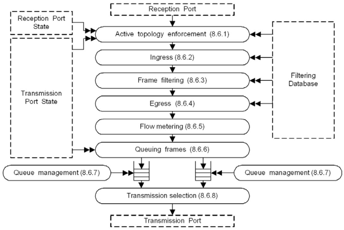
Figure 8-11—Forwarding Process functions
NOTE 1—IEEE Std 802.1Q, 2003 Edition, included frame formatting and FCS recalculation functions within the Forwarding Process. This standard now places those functions below the EISS interface, to allow the specification of additional methods for Bridge Port support of the EISS.
NOTE 2—IEEE Std 802.1D-2004 [B10], included priority mapping functions within the Forwarding Process. This standard now places this function below the ISS interface.
NOTE 3—The Forwarding Process models the MAC relay function and does not take into consideration what may occur once frames are passed to the Bridge Port for transmission. Conformant implementations of some media access methods can vary the transmission order in apparent violation of the transmission selection rules when observing frames on the medium. It may therefore not be possible to test conformance to this standard for some implementations simply by relating observed LAN traffic to the functionality of the forwarding process; tests also have to allow for the (conformant) behavior of the MAC.
Figure 8-4 illustrates the operation of the Forwarding Process in a single instance of frame relay between the Ports of a Bridge with two Ports.
8.6.1 Active topology enforcement
To prevent data loops and unwanted learning of source MAC addresses, the Forwarding Process determines the values (TRUE or FALSE) of the learning and forwarding controls (8.4) appropriate to each received frame and Bridge Port. If learning is TRUE for the reception Port and ingress filtering (8.6.2) would not cause the received frame to be discarded, the source address and VID are submitted to the Learning Process.
NOTE 1—VIDs are not applicable to MAC Bridges and only the source address is submitted to the Learning Process.
If forwarding is TRUE for the reception Port, and either the EVBMode parameter value (40.4) for the Port is not “EVB Bridge” or the value of the operReflectiveRelayControl parameter for the Port is FALSE, each Bridge Port, other than the reception Port, with forwarding TRUE is identified as a potential transmission Port. If forwarding is TRUE for the receiving Port and the EVBMode parameter value (40.4) for the Port is “EVB Bridge” and the operReflectiveRelayControl parameter value for the Port is TRUE, each Bridge Port, including the reception Port, with forwarding TRUE is identified as a potential transmission Port.
In an edge relay (ER), the forwarding process may set learning FALSE for all frames.
An SST Bridge supports a single active topology, the CST. For each Bridge Port, RSTP determines a single value for forwarding and a single value for learning (8.4) for all frames.
Bridges with MST, PBB-TE, or SPB capabilities use the VID of the received frame to determine forwarding and learning for that frame for each Bridge Port that is enabled, i.e., has MAC_Operational True and an Administrative Bridge Port State of Enabled, as follows:
If the Bridge supports PBB-TE, and the VID is an ESP-VID, forwarding is TRUE and learning is FALSE. Control over the active topology of each ESP is provided by configuration of Static Filtering Entries in the FDB (8.8.1, 25.10.1).
If the Bridge uses MSTP to configure the CIST, and the VID identifies a VLAN assigned to the CIST, forwarding and learning are as determined by MSTP (Clause 13) for the CIST.
If the Bridge uses MSTP to configure MSTIs, and the VID identifies a VLAN assigned to an MSTI calculated by MSTP, forwarding and learning are as determined by MSTP for that MSTI.
If the Bridge uses ISIS-SPB to configure the CIST, and the VID identifies a VLAN assigned to the CIST, forwarding and learning take the value of forwarding determined by ISIS-SPB (Clause 28) for the CIST.
If the Bridge uses ISIS-SPB, and the VID is used by SPBV as an SPVID, both forwarding and learning take the value of forwarding determined by ISIS-SPB for the SPT identified by that SPVID.
If the Bridge uses ISIS-SPB and the VID identifies a VLAN supported by SPBM, then for that VID
— Learning is False for all Bridge Ports;
Forwarding is True for the reception Port if and only if a Dynamic Filtering Entry for the frame's source address exists and specifies Forward for that Port; and
— Forwarding is True for all other Bridge Ports.
NOTE 2—Effective control over the egress component of an SPT for VLANs supported by SPBM is provided by ISIS-SPB configuration of (a) a Dynamic Filtering Entry for the VLAN's VID and Root MAC address (for unicast frames); and (b) MAC Address Registration Entries for the VID- and SPT-specific group MAC addresses (for multicast frames); and (c) a MAC Address Registration Entry for the VID to filter “All Unregistered Group Addresses” at all Ports.
All Bridges other than SST Bridges implement the MST Configuration Table (8.9.1). The use of VIDs to determine learning and forwarding, as required by this clause, shall be consistent with that table as follows. VIDs allocated by the MST Configuration Table (8.9.1) of value
— CIST-MSTID (0x000) are CIST VIDs.
— SPBM-MSTID (0xFFC) are Base VIDs supported by SPBM.
— SPBV-MSTID (0xFFD) are Base VIDs supported by SPBV.
— TE-MSTID (0xFFE) are ESP-VIDs supported by PBB-TE.
— SPVID-MSTID (0xFFFF) are VIDs reserved for use by ISIS-SPB as SPVIDs.
— All VIDs allocated to other values of MSTID are assigned to the MSTI identified by that MSTID.
NOTE 3—While the MST Configuration Table is capable of detailing the configuration of each SPVID, it captures the allocation of Base VIDs only. Individual allocation of SPVIDs are captured in the ISIS-SPB database, the SPB ECT Static Entry (12.25.4), and in the port VID translation tables. By specifying only the type of VID and its allocation to SPB, backwards compatibility with STP, RSTP, and MSTP is maintained.
8.6.1.1 Requirements for the use of reflective relay
VEPA ERs (8.6.3.1) used in EVB (Clause 40) require reflective relay (40.4, 8.6.1) to be enabled on an attached EVB Bridge SBP in order to ensure that all VSIs connected to the VEPA ER are able to receive frames transmitted on one of the other VSIs. The following requirements ensure that a device operates correctly when using reflective relay:
a) The operation of the device shall be such that it prevents the establishment of loops, i.e., the device shall not both request and provide reflective relay on the same port.
b) The device shall ensure that any frame that it transmits on a given port, and that is reflected back to the device through the attached Bridge Port, is filtered by the device in order to prevent it being delivered to the originating port.
c) Any device requesting reflective relay is responsible for performing frame replication as necessary for delivery to multiple ports.
NOTE—Information that can be used to assist in meeting these requirements is the source MAC address and the FID derived from the VID.
8.6.2 Ingress filtering
Each Port may support an Enable Ingress Filtering parameter. A frame received on a Port that is not in the member set (8.8.10) associated with the frame's VID shall be discarded if this parameter is set. The default value for this parameter is reset, i.e., Disable Ingress Filtering, for all Ports. Any Port that supports setting this parameter shall also support resetting it. The parameter may be configured by the management operations defined in Clause 12.
This function is not applicable to VLAN-unaware MAC Relays.
8.6.3 Frame filtering
The Forwarding Process takes filtering decisions, i.e., reduces the set of potential transmission Ports (8.6.1), for each received frame on the basis of
a) Destination MAC address;
b) VID;
c) Flow hash;
d) The information contained in the FDB for that MAC address and VID;
e) The default Group filtering behavior for the potential transmission Port (8.8.6);
in accordance with the definition of the FDB entry types (8.8.1, 8.8.3, and 8.8.4). The required behavior is summarized in 8.8.6, 8.8.9, Table 8-7, Table 8-8, and Table 8-9. Item b), specifying a VID value, is not applicable to VLAN-unaware MAC Relays. Flow hash is applicable only on Bridges supporting flow filtering (44.2).
Each of the reserved MAC addresses specified in Table 8-1 shall be permanently configured in the FDB in C-VLAN components and ERs. Each of the reserved MAC addresses specified in Table 8-2 shall be permanently configured in the FDB in S-VLAN components. Each of the reserved MAC addresses specified in Table 8-3 shall be permanently configured in the FDB in TPMR components. The FDB entries for reserved MAC addresses shall specify filtering for all Bridge Ports and all VIDs. Management shall not provide the capability to modify or remove entries for reserved MAC addresses.
The addresses in Table 8-1, Table 8-2, and Table 8-3 determine the scope of propagation of PDUs within a Bridged Network, as follows:
f) The Nearest Bridge group address is an address that no conformant TPMR component, S-VLAN component, C-VLAN component, or MAC Bridge can forward. PDUs transmitted using this destination address, or any of the other addresses that appear in all three tables, can therefore travel no further than those stations that can be reached via a single individual LAN from the originating station. Hence the Nearest Bridge group address is also known as the Individual LAN Scope group address.
g) The Nearest non-TPMR Bridge group address is an address that no conformant S-VLAN component, C-VLAN component, or MAC Bridge can forward; however, this address is relayed by a TPMR component. PDUs using this destination address, or any of the other addresses that appear in both Table 8-1 and Table 8-2 but not in Table 8-3, will be relayed by any TPMRs but will propagate no further than the nearest S-VLAN component, C-VLAN component, or MAC Bridge.
h) The Nearest Customer Bridge group address is an address that no conformant C-VLAN component or MAC Bridge can forward; however, it is relayed by TPMR components and S-VLAN components. PDUs using this destination address, or any of the other addresses that appear in Table 8-1 but not in either Table 8-2 or Table 8-3, will be relayed by TPMR components and S-VLAN components but will propagate no further than the nearest C-VLAN component or MAC Bridge.
Table 8-1—C-VLAN and MAC Bridge component Reserved addresses
<table><tr><td>Assignment</td><td>Value</td></tr><tr><td>Bridge Group Address, Nearest Customer Bridge group addressa</td><td>01-80-C2-00-00-00</td></tr><tr><td>IEEE MAC-specific Control Protocols group address</td><td>01-80-C2-00-00-01</td></tr><tr><td>IEEE 802.3 Slow_Protocols_Multicast address</td><td>01-80-C2-00-00-02</td></tr><tr><td>Nearest non-TPMR Bridge group address</td><td>01-80-C2-00-00-03</td></tr><tr><td>IEEE MAC-specific Control Protocols group address</td><td>01-80-C2-00-00-04</td></tr><tr><td>Reserved for future standardization</td><td>01-80-C2-00-00-05</td></tr><tr><td>Reserved for future standardization</td><td>01-80-C2-00-00-06</td></tr><tr><td>Metro Ethernet Forum ELMI protocol group addressb</td><td>01-80-C2-00-00-07</td></tr><tr><td>Provider Bridge Group Address</td><td>01-80-C2-00-00-08</td></tr><tr><td>Reserved for future standardization</td><td>01-80-C2-00-00-09</td></tr><tr><td>Reserved for future standardization</td><td>01-80-C2-00-00-0A</td></tr><tr><td>Reserved for future standardization</td><td>01-80-C2-00-00-0B</td></tr><tr><td>Reserved for future standardization</td><td>01-80-C2-00-00-0C</td></tr><tr><td>Provider Bridge MVRP Address</td><td>01-80-C2-00-00-0D</td></tr><tr><td>Individual LAN Scope group address<eq>^c</eq>, Nearest Bridge group address</td><td>01-80-C2-00-00-0E</td></tr><tr><td>Reserved for future standardization</td><td>01-80-C2-00-00-0F</td></tr></table>
$^{a}$ As stated in 13.41, in a Provider Edge Bridge, a C-VLAN component supporting a single service instance (i.e., with a single PEP) may forward (not filter) frames with the Nearest Customer Bridge Address as the destination address.
$^{b}$ This address is not exclusively reserved for this purpose; other uses are reserved for future standardization.
$^{c}$ It is intended that no IEEE 802.1 relay device will be defined that will forward frames that carry this destination address.
Table 8-2—S-VLAN component Reserved addresses
<table><tr><td>Assignment</td><td>Value</td></tr><tr><td>IEEE MAC-specific Control Protocols group address</td><td>01-80-C2-00-00-01</td></tr><tr><td>IEEE 802.3 Slow_Protocols_Multicast address</td><td>01-80-C2-00-00-02</td></tr><tr><td>Nearest non-TPMR Bridge group address</td><td>01-80-C2-00-00-03</td></tr><tr><td>IEEE MAC-specific Control Protocols group address</td><td>01-80-C2-00-00-04</td></tr><tr><td>Reserved for future standardization</td><td>01-80-C2-00-00-05</td></tr><tr><td>Reserved for future standardization</td><td>01-80-C2-00-00-06</td></tr><tr><td>Metro Ethernet Forum ELMI protocol group <eq>address^a</eq></td><td>01-80-C2-00-00-07</td></tr><tr><td>Provider Bridge Group Address</td><td>01-80-C2-00-00-08</td></tr><tr><td>Reserved for future standardization</td><td>01-80-C2-00-00-09</td></tr><tr><td>Reserved for future standardization</td><td>01-80-C2-00-00-0A</td></tr><tr><td>Individual LAN Scope group <eq>address^b</eq>, Nearest Bridge group address</td><td>01-80-C2-00-00-0E</td></tr></table>
$^{a}$ This address is not exclusively reserved for this purpose; other uses are reserved for future standardization.
$^{b}$ It is intended that no IEEE 802.1 relay device will be defined that will forward frames that carry this destination address.
Table 8-3—TPMR component Reserved addresses
<table><tr><td>Assignment</td><td>Value</td></tr><tr><td>IEEE MAC-specific Control Protocols group address</td><td>01-80-C2-00-00-01</td></tr><tr><td>IEEE 802.3 Slow_Protocols_Multicast address</td><td>01-80-C2-00-00-02</td></tr><tr><td>IEEE MAC-specific Control Protocols group address</td><td>01-80-C2-00-00-04</td></tr><tr><td>Individual LAN Scope group addressa, Nearest Bridge group address</td><td>01-80-C2-00-00-0E</td></tr></table>
$^{a}$ It is intended that no IEEE 802.1 relay device will be defined that will forward frames that carry this destination address.
NOTE 1—The reserved MAC addresses specified in Table 8-1, Table 8-2, and Table 8-3 determine the span of connectivity for the protocol frames using the address; they do not identify the protocol. The protocols are identified by the EtherType field following the address fields.
NOTE 2—An instance of IEEE 802.1AX Link Aggregation Control Protocol (LACP) intended to operate between non-TPMR Bridges, even through a TPMR, can use the Nearest non-TPMR Bridge group address. See K.2 for discussion of the use of TPMRs in a link using LACP.
8.6.3.1 Virtual edge port aggregator (VEPA) filtering
A VEPA ER filters frames as follows.
If the receiving port is a DRP, then the URP shall be selected as the only transmission Port.
If the receiving port is a URP, then in addition to the filtering specified in 8.6.3, if there is a filtering entry that specifies forwarding for the source MAC address and VLAN of the frame for any DRP, then that DRP shall be removed from the list of potential transmission Ports.
8.6.4 Egress filtering
This function is not applicable to VLAN-unaware MAC Relays.
Any Port that is not in the member set (8.8.10) for the frame's VID is removed from the set of potential egress Ports.
8.6.5 Flow classification and metering
The Forwarding Process may apply flow classification and metering to frames that are received on a Bridge Port and have one or more potential transmission ports.
Flow classification identifies a subset of traffic (frames) that may be subject to the same treatment in terms of metering and forwarding. Flow classification rules may be based on
a) Destination MAC address
b) Source MAC address
c) VID
d) Priority
Item c), specifying a VID value, is not applicable to VLAN-unaware MAC Relays.
Frames classified using the same set of classification rules are subject to the same flow meter. The flow meter can change the drop_eligible parameter associated with each frame and can discard frames on the basis of the following parameters for each received frame and previously received frames, and the time elapsed since those frames were received:
e) The received value of the drop_eligible parameter
f) The mac_service_data_unit size
The flow meter shall not base its decision on the parameters of frames received on other Bridge Ports, or on any other parameters of those Ports. The metering algorithm described in the Metro Ethernet Forum (MEF) Technical Specification 10.3 (MEF 10.3) [B45] should be used.
NOTE 1—Changing the value of the drop_eligible parameter may change the contents of the frame, depending on how the frame is tagged when transmitted, which may then require updating the frame_check_sequence. Mechanisms for conveying information from ingress to egress that the frame_check_sequence may require updating are implementation dependent.
NOTE 2—The flow meter described here can encompass a number of meters, each with a simpler specification. However, given the breadth of implementation choice permitted, further structuring to specify, for example, that frames can bypass a meter or are subject only to one of a number of meters provides no additional information.
NOTE 3—Although flow metering is applied after egress (Figure 8-11), the meter(s) operate per reception Port (see first sentence of 8.6.5), not per potential transmission Port(s).
8.6.6 Queuing frames
The Forwarding Process shall queue each received frame to each of the potential transmission Ports (8.6.1, 8.6.3, 8.6.4).
NOTE 1—The Forwarding Process is modeled as receiving a frame as the parameters of a data indication and transmitting through supplying the parameters of a data request. Queuing a frame awaiting transmission amounts to placing the parameters of a data request on an outbound queue.
The Forwarding Process provides storage for queued frames, awaiting an opportunity to submit these for transmission. The order of frames received on the same Bridge Port shall be preserved for
a) unicast frames with a given VID, priority, flow hash, and destination address and source address combination;
b) multicast frames with a given VID, priority, flow hash, and destination address.
Flow hash is applicable only on Bridges supporting flow filtering (44.2).
VID is not applicable to VLAN-unaware MAC Relays and the above combinations will exclude any reference to VID when applied to MAC Bridges.
The Forwarding Process provides one or more queues for a given Bridge Port, each corresponding to a distinct traffic class. Each frame is mapped to a traffic class using the Traffic Class Table for the Port and the frame's priority. Traffic class tables may be managed. Table 8-4 shows the recommended mapping for the number of classes implemented, in implementations that do not support the credit-based shaper transmission selection algorithm (8.6.8.2). The requirements for priority to traffic class mappings in implementations that support the credit-based shaper transmission selection algorithm are defined in 34.5. Up to eight traffic classes may be supported, allowing separate queues for each priority.
NOTE 2—Different numbers of traffic classes may be implemented for different Ports. Ports with media access methods that support a single transmission priority, such as Ethernet, can support more than one traffic class.
NOTE 3—A queue in this context is not necessarily a single FIFO data structure. A queue is a record of all frames of a given traffic class awaiting transmission on a given Bridge Port. The structure of this record is not specified. The transmission selection algorithm (8.6.8) determines which traffic class, among those classes with frames available for transmission, provides the next frame for transmission. The method of determining which frame within a traffic class is the next available frame is not specified beyond conforming to the frame ordering requirements of this subclause. This allows a variety of queue structures such as a single FIFO, or a set of FIFOs with one for each pairing of ingress and egress ports (i.e., Virtual Output Queuing), or a set of FIFOs with one for each VLAN or priority, or hierarchical structures.
In a congestion aware Bridge (Clause 30), the act of queuing a frame for transmission on a Bridge Port can result in the Forwarding Process generating a CNM. The CNM is injected back into the Forwarding Process (8.6.1) as if it had been received on that Bridge Port.
Table 8-4—Recommended priority to traffic class mappings
<table><tr><td rowspan="2" colspan="2"></td><td colspan="8">Number of available traffic classes</td></tr><tr><td>1</td><td>2</td><td>3</td><td>4</td><td>5</td><td>6</td><td>7</td><td>8</td></tr><tr><td rowspan="8">Priority</td><td>0 (Default)</td><td>0</td><td>0</td><td>0</td><td>0</td><td>0</td><td>1</td><td>1</td><td>1</td></tr><tr><td>1</td><td>0</td><td>0</td><td>0</td><td>0</td><td>0</td><td>0</td><td>0</td><td>0</td></tr><tr><td>2</td><td>0</td><td>0</td><td>0</td><td>1</td><td>1</td><td>2</td><td>2</td><td>2</td></tr><tr><td>3</td><td>0</td><td>0</td><td>0</td><td>1</td><td>1</td><td>2</td><td>3</td><td>3</td></tr><tr><td>4</td><td>0</td><td>1</td><td>1</td><td>2</td><td>2</td><td>3</td><td>4</td><td>4</td></tr><tr><td>5</td><td>0</td><td>1</td><td>1</td><td>2</td><td>2</td><td>3</td><td>4</td><td>5</td></tr><tr><td>6</td><td>0</td><td>1</td><td>2</td><td>3</td><td>3</td><td>4</td><td>5</td><td>6</td></tr><tr><td>7</td><td>0</td><td>1</td><td>2</td><td>3</td><td>4</td><td>5</td><td>6</td><td>7</td></tr></table>
NOTE—The rationale for these mappings is discussed in Annex I.
8.6.7 Queue management
A frame queued for transmission on a Port shall be removed from that queue
a) Following a transmit data request. No further attempt shall be made to transmit the frame on that Port even if the transmission is known to have failed.
b) If that is necessary to ensure that the maximum Bridge transit delay (6.5.6) will not be exceeded at the time at which the frame would subsequently be transmitted.
c) If the transmission Port is no longer forwarding for that frame (8.4, 8.6.1). Frames entering the queue subsequent to the transition out of the Forwarding state (e.g., CFM frames from Down MPs, as described in 22.1, Figure 22-4, and Figure 22-7) are not discarded.
NOTE 1—CFM frames may be excepted, and not removed from the queue, on a transition out of the Forwarding state (see 22.1.3).
The frame can be removed from the queue, and not subsequently transmitted
d) If the time for which buffering is guaranteed has been exceeded for that frame
e) By a queue management algorithm that attempts to improve the QoS provided by deterministically or probabilistically managing the queue depth based on the current and past queue depths.
Removal of a frame from a queue for any particular Port does not affect queuing of that frame for transmission on any other Port.
NOTE 2—Applicable queue management algorithms include RED (random early detection), and WRED (weighted random early detection) (IETF RFC 2309 [B22]). If the Bridge supports drop precedence, i.e., is capable of decoding or encoding the drop_eligible parameter from or to the PCP field of VLAN tags (6.9.3), the algorithm should exhibit a higher probability of dropping frames with drop_eligible True.
The probability of removing a frame with drop_eligible set shall not be less than that of removing a frame with drop_eligible False, all other conditions being equal. If a queue management algorithm is implemented, it should preferentially discard frames with drop_eligible True. If a Bridge supports encoding or decoding of drop_eligible from the PCP field of a VLAN tag (6.9.3) on any of its Ports, then it shall implement a boolean parameter Require Drop Encoding on each of its Ports with default value FALSE. If Require Drop Encoding is True and the Bridge Port cannot encode particular priorities with drop_eligible, then frames queued with those priorities and drop_eligible True shall be discarded and not transmitted.
8.6.8 Transmission selection
For each Port, frames are selected for transmission on the basis of the traffic classes that the Port supports and the operation of the transmission selection algorithms supported by the corresponding queues on that Port. For a given Port and supported value of traffic class, frames are selected from the corresponding queue for transmission if and only if
a) The operation of the transmission selection algorithm supported by that queue determines that there is a frame available for transmission; and
b) For each queue corresponding to a numerically higher value of traffic class supported by the Port, the operation of the transmission selection algorithm supported by that queue determines that there is no frame available for transmission.
In a port of a Bridge or station that supports PFC, a frame of priority n is not available for transmission if that priority is paused (i.e., if Priority_Paused[n] is TRUE (see 36.1.3.2)) on that port. When Transmission Selection is running above Link Aggregation, a frame of priority n is not available for transmission if that priority is paused on the physical port to which the frame is to be distributed.
NOTE 1—Two or more priorities can be combined in a single queue. In this case if one or more of the priorities in the queue are paused, it is possible for frames in that queue not belonging to the paused priority to not be scheduled for transmission.
NOTE 2—Mixing PFC and non-PFC priorities in the same queue results in non-PFC traffic being paused causing congestion spreading, and therefore is not recommended.
The strict priority transmission selection algorithm defined in 8.6.8.1 shall be supported by all Bridges as the default algorithm for selecting frames for transmission. The credit-based shaper transmission selection algorithm defined in 8.6.8.2, and the ETS algorithm defined in 8.6.8.3 may be supported in addition to the strict priority algorithm. Further transmission selection algorithms, selectable by management means, may be supported as an implementation option so long as the requirements of 8.6.6 are met.
The Transmission Selection Algorithm Table for a given Port assigns, for each traffic class that the Port supports, the transmission selection algorithm that is to be used to select frames for transmission from the corresponding queue. Transmission Selection Algorithm Tables may be managed, and allow the identification of vendor-specific transmission selection algorithms. The transmission selection algorithms are identified in the Transmission Selection Algorithm Table by means of integer identifiers, as defined in Table 8-5.
In implementations that do not support the credit-based shaper transmission selection algorithm, the recommended default configuration for the Transmission Selection Algorithm Tables is to assign the strict priority transmission selection algorithm to all supported traffic classes. In implementations that support the credit-based shaper transmission selection algorithm, the recommended default configuration for the Transmission Selection Algorithm Tables is defined in 34.5.
8.6.8.1 Strict priority algorithm
For a given queue that supports strict priority transmission selection, the algorithm determines that there is a frame available for transmission if the queue contains one or more frames. The order in which frames are selected for transmission from the queue shall maintain the ordering requirement specified in 8.6.6.
Table 8-5—Transmission selection algorithm identifiers
<table><tr><td>Transmission selection algorithm</td><td>Identifier</td></tr><tr><td>Strict priority (8.6.8.1)</td><td>0</td></tr><tr><td>Credit-based shaper (8.6.8.2)</td><td>1</td></tr><tr><td>Enhanced Transmission Selection (ETS) (8.6.8.3)</td><td>2</td></tr><tr><td>Reserved for future standardization</td><td>3–254</td></tr><tr><td>Vendor-specific Transmission Selection algorithm value for use with DCBX (D.2.9.8)</td><td>255</td></tr><tr><td>Vendor-specific</td><td>A four-octet integer, where the most significant 3 octets hold an OUI or CID value, and the least significant octet holds an integer value in the range 0–255 assigned by the owner of the OUI or CID.</td></tr></table>
8.6.8.2 Credit-based shaper algorithm
For a given queue that supports credit-based shaper transmission selection, the algorithm determines that a frame is available for transmission if the following conditions are all true:
a) The queue contains one or more frames.
b) The transmitAllowed signal for the queue is TRUE.
The order in which frames are selected for transmission from the queue shall maintain the ordering requirement specified in 8.6.6.
The following external parameters are associated with each queue that supports the operation of the credit-based shaper algorithm:
c) portTransmitRate. The transmission rate, in bits per second, that the underlying MAC Service that supports transmission through the Port provides. The value of this parameter is determined by the operation of the MAC.
d) idleSlope. The rate of change of credit, in bits per second, when the value of credit is increasing (i.e., while transmit is FALSE). The value of idleSlope can never exceed portTransmitRate. The value of idleSlope for a given queue is determined by the value of the operIdleSlope(N) parameter for that queue, as defined in 34.3.
The following internal parameters are associated with each queue that supports the credit-based shaper algorithm:
e) transmit. Takes the value TRUE for the duration of a frame transmission from the queue; FALSE when any frame transmission from the queue has completed.
f) credit. The transmission credit, in bits, that is currently available to the queue. If, at any time, there are no frames in the queue, and the transmit parameter is FALSE, and credit is positive, then credit is set to zero.
g) sendSlope. The rate of change of credit, in bits per second, when the value of credit is decreasing (i.e., while transmit is TRUE). The value of sendSlope is defined as follows:
$$
s e n d S l o p e = (i d l e S l o p e - p o r t T r a n s m i t R a t e)
$$
h) transmitAllowed. Takes the value TRUE when the credit parameter is zero or positive; FALSE when the credit parameter is negative.
NOTE 1—The value of credit is naturally constrained by the operating parameters for the algorithm, and also by the operation of any higher priority queues that use this algorithm. The lowest value that credit can reach depends on sendSlope and the largest frame that will be transmitted from the queue. This largest frame size is a consequence of the type of traffic that is being transmitted using the queue, rather than a limit imposed by the algorithm or by management. The highest value that can be accumulated in credit depends on idleSlope and the length of time that the algorithm may have to wait when the queue is not empty and there is other traffic being transmitted through the Port; for any given queue, that length of time is bounded, as discussed in Annex L, which also illustrates how the algorithm operates under varying conditions, and how its operation affects the maximum latency that can be experienced by SR traffic.
NOTE 2—In order for the credit-based shaper algorithm to operate as intended, it is necessary for all traffic classes that support the algorithm to be numerically higher than any traffic classes that support the strict priority algorithm defined in 8.6.8.1. The mapping of priorities onto traffic classes, and the choice of traffic classes that support particular transmission selection algorithms, is defined in 34.5.
Traffic classes using the credit-based shaper algorithm shall not use PFC and shall ignore the setting of the bits related to such classes in the PFC Enable bit vector (see D.2.11.6)
8.6.8.3 ETS algorithm
If ETS is enabled for a traffic class, transmission selection is performed based on the allocation of bandwidth to that traffic class. Bandwidth is distributed among ETS traffic classes that support ETS algorithm such that each traffic class is allocated available bandwidth in proportion to its TCBandwidth (see Clause 37).
For a given queue that supports ETS, the algorithm determines that there is a frame available for transmission if the following conditions are all true:
a) The queue contains one or more frames;
b) The ETS algorithm (37.3) determines that a frame should be transmitted from the queue; and
c) There are no frames available for transmission for any queues running strict priority or credit-based shaper algorithms.
The order in which frames are selected for transmission from the queue shall maintain the ordering requirement specified in 8.6.6.
8.7 The Learning Process
The Learning Process receives the source MAC addresses and VIDs, or only the source MAC addresses in the case of VLAN-unaware MAC Relays, of received frames from the Forwarding Process, subject to active topology enforcement (8.6.1) and the application of ingress filtering (8.6.2). The Learning Process is not invoked (8.6.1) for frames whose VID is an ESP-VID or identifies a VLAN supported by SPBM.
When invoked, the Learning Process shall create or update a Dynamic Filtering Entry (8.8.3) that specifies the reception Port for the frame's source address and, in the case of VLAN Bridge components, the frame's VID, if and only if the source address is an individual address, i.e., is not a group address, the resulting number of entries would not exceed the capacity of the FDB, and the filtering utility criteria for the receiving Bridge Port are met, as specified below.
If the FDB is already filled to capacity, but a new entry would otherwise be made, then an existing entry may be removed to make room for the new entry.
The purpose of filtering utility criteria is to reduce the capacity requirements of the FDB and to reduce the time for which service can be denied (6.5.1) by retaining filtering information learned prior to a change in the physical topology of the network. Filtering utility criteria shall be applied to the learning and retention of information for each FID (8.8.8). In Bridges other than EVB Bridges (5.23), enhanced filtering utility criteria may be implemented for any Bridge Port as specified below (8.7.2); if implemented, both the default (8.7.1) and the enhanced criteria shall be selectable by management. In EVB Bridges, the enhanced filtering utility criteria shall be implemented for all Bridge Ports, and the default filtering utility criteria shall not be implemented.
Figure 8-5 illustrates the operation of the Learning Process in the inclusion of station location information carried by a single frame, received on one of the Ports of a Bridge, in the FDB.
8.7.1 Default filtering utility criteria
The default for a VLAN Bridge is that the member set (8.8.10) for the frame's VID includes at least one Port.
NOTE—If the member set for a given VID is empty, that VID is not currently active, and the Bridge will filter all frames destined for that VID, regardless of their destination address.
The default filtering utility criteria are always met for MAC Bridges.
8.7.2 Enhanced filtering utility criteria
For a VLAN Bridge, the enhanced criteria are satisfied if at least one VID that uses the FID includes the reception Port and at least one other Port with a Port State of Learning or Forwarding in its member set, and:
a) The operPointToPointMAC parameter is FALSE for the reception Port; or
b) Ingress for the VID is permitted through a third Port; or
c) The reception Port has reflective relay enabled (40.4.2).
NOTE—The third port can, but is not required to, be in the member set.
For a MAC Bridge, the enhanced criteria are satisfied if there exists at least one Port different than the reception Port with a Port State of Learning or Forwarding, and:
d) The operPointToPointMAC parameter is FALSE for the reception Port; or
e) There exists third Port with a Port State of Learning or Forward; or
f) The reception Port has reflective relay enabled (40.4.2).
8.7.3 Ageing of Dynamic Filtering Entries
Dynamic Filtering Entries shall be automatically removed after a specified time, the Ageing Time, has elapsed since the entry was created or last updated by the Learning Process.
The ageing out of Dynamic Filtering Entries ensures that end stations that have been moved to a different part of the network will not be permanently prevented from receiving frames. It also takes account of changes in the active topology of the network that can cause end stations to appear to move from the point of view of the Bridge; i.e., the path to those end stations subsequently lies through a different Bridge Port.
The Ageing Time may be set by management (Clause 12). A range of applicable values and a recommended default is specified in Table 8-6; this is suggested to remove the need for explicit configuration in most cases. If the value of Ageing Time can be set by management, the Bridge shall have the capability to use values in the range specified, with a granularity of 1 s.
NOTE—The granularity is specified in order to establish a common basis for the granularity expressed in the management operations defined in Clause 12, not to constrain the granularity of the actual timer supported by a conformant implementation. If the implementation supports a granularity other than 1 s, then it is possible that the value read back by management following a Set operation will not match the actual value expressed in the Set.
Table 8-6—Ageing time parameter value
<table><tr><td>Parameter</td><td>Recommended default value</td><td>Range</td></tr><tr><td>Ageing time</td><td>300.0 s</td><td>10.0–1 000 000.0 s</td></tr></table>
The STP specified in Clause 8 of IEEE Std 802.1D, 1998 Edition [B9], includes a procedure for notifying all Bridges in the network of topology change. It specifies a short value for the Ageing Timer, to be enforced for a period after any topology change (8.3.5 of IEEE Std 802.1D, 1998 Edition [B9]). While the topology is not changing, this procedure allows normal ageing to accommodate extended periods during which addressed end stations do not generate frames themselves, perhaps through being powered down, without sacrificing the ability of the network to continue to provide service after automatic configuration.
8.8 The Filtering Database (FDB)
The FDB supports queries by the Forwarding Process to determine whether received frames, with given values of, destination MAC address, and for VLAN Bridge components, VID, are to be forwarded through a given potential transmission Port (8.6.1, 8.6.3, 8.6.4). It can also be used, by SPBM (8.6.1), to determine whether received frames with given values of source B-MAC address and B-VID, are to be forwarded from a given reception Port. The FDB contains filtering information in the form of filtering entries that are either
a) Static, and explicitly configured by management action; or
b) Dynamic, and automatically entered into the FDB by the normal operation of the Bridge and the protocols it supports.
Two entry types are used to represent static filtering information. The Static Filtering Entry represents static information in the FDB for individual and for group MAC addresses. It allows administrative control of
c) Forwarding of frames with particular destination addresses; and
d) The inclusion in the FDB of dynamic filtering information associated with Extended Filtering Services, and use of this information.
The FDB shall contain entries of the Static Filtering Entry type.
The Static VLAN Registration Entry represents all static information in the FDB for VLANs. It allows administrative control of
e) Forwarding of frames with particular VIDs;
f) The inclusion/removal of tag headers in forwarded frames; and
g) The inclusion in the FDB of dynamic VLAN membership information, and use of this information.
The FDB associated with VLAN Bridge components may contain entries of the Static VLAN Registration Entry type. The Static VLAN Registration Entry type is not applicable to MAC Bridge components.
Static filtering information is added to, modified, and removed from the FDB only under explicit management control except when PBB-TE IPS is deployed, in which case the static filtering information for traffic associated with IPGs configured on the Bridge is added to, modified, and removed from the FDB only under the direction of IPS Control (26.11.3). It shall not be automatically removed by any ageing mechanism. Management of static filtering information may be carried out by use of the remote management capability provided by Bridge Management (8.12) using the operations specified in Clause 12.
Four entry types are used to represent dynamic filtering information:
h) Each Dynamic Filtering Entry specifies the Port through which a frame with a given individual MAC address, and in the case of VLAN Bridge components, VID, has been or can be received. Dynamic Filtering Entries can be created and updated by the Learning Process (8.7) and by ISIS-SPB. Entries that are updated by the Learning Process are subject to ageing and removal by the FDB.
NOTE 1—ISIS-SPB has to create the Dynamic Filtering Entries for VLANs supported by SPBM, since learning is not used. Initial creation of these entries does no harm for VLANs supported by SPBV (when learning is used) as it can reduce flooding of frames to unknown destinations.
i) MAC Address Registration Entries support the registration of MAC addresses. They are created, updated, and removed by MMRP in support of Extended Filtering Services (8.8.4 and Clause 10) and by ISIS-SPB. If the Restricted_MAC_Address_Registration management control (10.12.2.3) is TRUE, then the creation of a MAC Address Registration Entry by MMRP is not permitted unless a Static Filtering Entry exists that permits dynamic registration for the Group concerned.
j) Dynamic VLAN Registration Entries are used to specify the Ports on which VLAN membership has been dynamically registered. They are not applicable to MAC Bridge components. They are created, updated, and removed by MVRP, MIRP, and ISIS-SPB, in support of automatic VLAN membership configuration (Clause 11 and Clause 39). The MVRP controlled Dynamic VLAN Registration Entries are subject to the state of the Restricted_VLAN_Registration management control (11.2.3.2.3). If the value of this control is TRUE, then the creation of a Dynamic VLAN Registration Entry is not permitted unless a Static VLAN Registration Entry exists that permits dynamic registration for the VID concerned.
k) Dynamic Reservation Entries are used to specify the Ports on which stream reservations have been made. They are created, updated, and removed by the operation of SRP defined in Clause 35.
Static Filtering Entries and MAC Address Registration Entries comprise
1) A MAC address specification;
m) A VID;
n) A Port Map, with a control element for each outbound Port to specify filtering for, that MAC address specification, and in the case of VLAN Bridge components, that VID.
Item m), and any reference to VIDs, are not applicable to MAC Bridge components.
Dynamic Filtering Entries comprise
o) A MAC address specification;
p) A locally significant FID (see 8.8.8);
q) A Port Map, with a control element for each outbound Port to specify filtering for, that MAC address specification, and in the case of VLAN Bridge components, for the VID(s) allocated to that FID.
Item p) and any reference to VIDs and FIDs are not applicable to MAC Bridge components.
The Port Map in Static and Dynamic Filtering Entries may contain a connection_identifier (8.8.12) for each outbound Port.
Static and Dynamic VLAN Registration Entries comprise
r) A VID;
s) A Port Map, with a control element for each outbound Port to specify filtering for the VID.
Static and Dynamic VLAN Registration Entries are not applicable to MAC Bridge components.
Dynamic Reservation Entries comprise
t) A MAC address specification;
u) A VID;
v) A Port Map, with a control element for each outbound Port to specify filtering for that MAC address specification, and in the case of VLAN Bridge components, in the VLAN specified by the VID.
Dynamic filtering information may be read by use of the remote management capability provided by Bridge Management (8.12) using the operations specified in Clause 12.
The Filtering Services supported by a Bridge (Basic and Extended Filtering Services) determine the default behavior of the Bridge with respect to the forwarding of frames destined for group MAC addresses. In Bridges that support Extended Filtering Services, the default forwarding behavior for group MAC addresses, for each Port, and for each VID, can be configured both statically and dynamically by means of Static Filtering Entries and/or MAC Address Registration Entries that can carry the following MAC address specifications:
w) All Group Addresses, for which no more specific Static Filtering Entry exists;
x) All Unregistered Group Addresses (i.e., all group MAC addresses for which no MAC Address Registration Entry exists), for which no more specific Static Filtering Entry exists.
NOTE 2—The All Group Addresses specification in item w), when used in a Static Filtering Entry with an appropriate control specification, provides the ability to configure a Bridge that supports Extended Filtering Services to behave as a Bridge that supports only Basic Filtering Services on some or all of its Ports. This might be done for the following reasons:
— The Ports concerned serve “legacy” devices that wish to receive multicast traffic, but are unable to register Group membership;
— The Ports concerned serve devices that need to receive all multicast traffic, such as routers or diagnostic devices.
The FDB shall support the creation, updating, and removal of Dynamic Filtering Entries by the Learning Process (8.7). In Bridges that support Extended Filtering Services, the FDB shall support the creation, updating, and removal of MAC Address Registration Entries by MMRP (Clause 10). In Bridges that support SPBM, Dynamic Filtering Entries are populated by ISIS-SPB (Clause 28). In Bridges that support SPBV the Dynamic Filtering Entries are created and updated by the Learning Process (8.7) and the use of ISIS-SPB for this operation is optional (28.12.9).
SPB (27.10) allocates SPVIDs dynamically to support shortest path bridging of frames assigned to one or more VLANs, each identified by a Base VID (Clause 3). A Static Filtering Entry should not be created for an SPVID, irrespective of whether that SPVID is currently used, and SPVIDs should not be used in registration protocols that create MAC Address Registration Entries or Dynamic VLAN Registration Entries. In an SPT Bridge, configuration or registration of an FDB entry with the Base VID of a VLAN supported by SPBV shall cause the Bridge to filter frames as if that entry was also present for every one of the SPVIDs for that Base VID.
In Bridges that support SRP, the FDB shall support the creation, updating, and removal of Dynamic Reservation Entries by SRP (Clause 35).
Figure 8-4 illustrates use of the FDB by the Forwarding Process in a single instance of frame relay between the Ports of a Bridge with two Ports.
Figure 8-5 illustrates the creation or update of a dynamic entry in the FDB by the Learning Process. The entries in the FDB, associated with VLAN Bridge components, allow MAC address information to be learned independently for each VID or set of VIDs, by relating a MAC address to the VID or set of VIDs on which that address was learned.
NOTE 3—The ability to create VLAN-dependent FDB entries allows a VLAN Bridge to support multiple end stations with the same individual MAC address residing on different VLANs. It also supports end stations with multiple interfaces, each using the same individual MAC address, as long as not more than one end station or interface that uses a given MAC address resides in a given VLAN.
Figure 8-6 illustrates the operation of the Spanning Tree Protocol Entity (8.10), which operates STP, and its notification of the FDB of changes in active topology signaled by that protocol.
There are no standardized constraints on the size of the FDB in an implementation for which conformance to this standard is claimed. The PICS proforma in Annex A requires the following to be specified for a given implementation:
y) The total number of entries (Static Filtering Entries, Dynamic Filtering Entries, MAC Address Registration Entries, Static VLAN Registration Entries, Dynamic VLAN Registration Entries, and Dynamic Reservation Entries) that the implementation of the FDB can support, and
z) Of that total number, the total number of VLAN Registration Entries (static and dynamic) that the FDB can support.
8.8.1 Static Filtering Entries
A Static Filtering Entry specifies
a) A MAC address specification, comprising
1) An individual MAC address; or
2) A group MAC address; or
3) All Individual Addresses, for which no more specific Filtering Entry exists; or
4) All Group Addresses, for which no more specific Static Filtering Entry exists; or
5) All Unregistered Group Addresses, for which no more specific Static Filtering Entry exists.
b) A VID specification, comprising
1) The VID of a specific VLAN to which the static filtering information applies; or
2) The wildcard VID (Table 9-2), indicating that the static filtering information applies to all VIDs for which no specific Static Filtering Entry exists.
c) A Port Map, containing a control element for each outbound Port, specifying that a frame with a destination MAC address, and in the case of VLAN Bridge components, VID that meets this specification is to be
1) Forwarded, independently of any dynamic filtering information held by the FDB; or
2) Filtered, independently of any dynamic filtering information; or
3) Forwarded or filtered on the basis of dynamic filtering information, or on the basis of the default Group filtering behavior for the outbound Port (8.8.6) if no dynamic filtering information is present specifically for the MAC address.
The Port Map may contain a connection_identifier (8.8.12) for each outbound Port.
MAC Bridges shall have the capability to support the first two values for the MAC address specification, and all three values for each control element for all Static Filtering Entries [i.e., shall have the capability to support item a1), item a2), item c1), item c2), and item c3)]. All VLAN Bridges shall have the capability to support the first two values for the MAC address specification, both values of the VID specification, and all three values for each control element for all Static Filtering Entries [i.e., shall have the capability to support item a1), item a2), item b1), item b2), item c1), item c2), and item c3)]. All Bridges supporting PBB-TE or SPT Bridges shall, in addition, support items a3) and a4) for ESP-VIDs (8.9) or VIDs identifying VLANs supported by SPBM, respectively, and shall always have in their FDBs Static Filtering Entries specifying items a3) and a4), and a Port Map specifying filtering for each outbound port, for every ESP-VID or SPBM VID, respectively.
A Bridge that supports Extended Filtering Services shall have the capability to support items a1), a2), a4), and a5) for the MAC address specification and all three control element values for all Static Filtering Entries.
For a given MAC address specification, a separate Static Filtering Entry with a distinct Port Map may be created for each VID from which frames are received by the Forwarding Process.
In addition to controlling the forwarding of frames, Static Filtering Entries provide the Registrar Administrative Control values for MMRP (Clause 10). Static configuration of forwarding of a specific destination MAC address to an outbound port indicates Registration Fixed on that port, which indicates a desire to receive the specific frames even in the absence of dynamic information. Static configuration of filtering of frames that might otherwise be sent to an outbound port indicates Registration Forbidden. The absence of a Static Filtering Entry for a MAC address, or the configuration of forwarding or filtering on the basis of dynamic filtering information, indicates Normal Registration.
8.8.2 Static VLAN Registration Entries
A Static VLAN Registration Entry specifies
a) The VID to which the static filtering information applies;
b) A Port Map, consisting of a control element for each outbound Port, specifying
1) The Registrar Administrative Control values for MVRP (Clause 11) and MIRP (Clause 39) for the VID. In addition to providing control over the operation of MVRP and MIRP, these values can also directly affect the forwarding behavior of the Bridge, as described in 8.8.10. The values that can be represented are
i) Registration Fixed (New ignored); or
ii) Registration Fixed (New propagated); or
iii) Registration Forbidden; or
i) Normal Registration.
2) Whether frames are to be VLAN-tagged or untagged when transmitted. The entries in the Port Map that specify untagged transmission compose the untagged set for the VID. The untagged set is empty if no Static VLAN Registration Entry exists for the VID.
Static VLAN Registration Entries are not applicable to MAC Bridge components.
A separate Static VLAN Registration Entry with a distinct Port Map may be created for each VID. All Bridges shall be capable of supporting all values for each control element for all Static VLAN Registration Entries; however, the ability to support more than one untagged VID on egress on any given Port is optional (see 5.4).
NOTE 1—In other words, it is possible to configure any VID as untagged on egress, but it is not necessarily possible to configure more than one VID as untagged on egress. It is an implementation option about whether only a single untagged VID per Port on egress is supported or whether multiple untagged VIDs per Port on egress are supported. When a single untagged VID per Port is supported, that VID is not necessarily the same as the PVID.
The initial state of the Permanent Database contains a Static VLAN Registration Entry for the VID corresponding to the Default PVID (Table 9-2). The Port Map in this entry specifies Registration Fixed and forwarding untagged for all Ports of the Bridge. This entry may be modified or removed from the Permanent Database by means of the management operations defined in Clause 12 if the implementation supports these operations.
NOTE 2—This initial state causes the default tagging state for the PVID to be untagged, and for all other VIDs to be tagged, unless otherwise configured; however, the management configuration mechanisms allow any VID (including the PVID) to be specified as VLAN-tagged or untagged on any Port.
NOTE 3—For VLANs supported by SPBV the Filtering specified by a static VLAN registration entry for the Base VID is applied for all SPVIDs associated with that Base VID.
8.8.3 Dynamic Filtering Entries
A Dynamic Filtering Entry specifies
a) An individual MAC address;
b) The FID, an identifier assigned by the MAC Bridge (8.8.8) to identify a set of VIDs for which no more than one Dynamic Filtering Entry can exist for any individual MAC address;
NOTE 1—An FID identifies a set of VIDs among which Shared VLAN Learning (SVL) (3.204) takes place. Any pair of FIDs identifies two sets of VIDs between which Independent VLAN Learning (IVL) (3.94) takes place. The allocation of FIDs by a Bridge is described in 8.8.8.
c) A Port Map specifying forwarding for the destination MAC address and FID to a single Port or, in the case of ECMP with flow filtering (44.1, 44.2), to a set of Ports from which one must be selected.
Item b), and any reference to FIDs and VIDs in the list above, are not applicable to MAC Bridge components.
The Port Map may contain a connection_identifier (8.8.12) for each outbound Port.
Dynamic Filtering Entries can be created, updated, and removed by the Learning Process (8.7). They shall be automatically removed after a specified time, the Ageing Time (8.7.3), has elapsed since the entry was created or last updated.
Dynamic Filtering Entries can also be created and updated by SPB (Clause 27). ISIS-SPB (Clause 28) refreshes these entries, so they are not aged out by the normal operation of the Learning Process. These entries are used by SPBM (Clause 27) to support both unicast loop mitigation (6.5.4.2) and multicast loop prevention (6.5.4.1) for active topology enforcement (8.6.1) as well as to locate end stations. Entries indicating a set of potential forwarding ports from which one must be selected are used by ECMP with flow filtering. SPBV updates Dynamic Filtering Entries by the normal Learning Process, but they may also be controlled by ISIS-SPB. This allows entries for the higher layer entities in a Bridge (see Figure 8-11) to be populated rapidly after any topology change.
No more than one Dynamic Filtering Entry shall be created in the FDB for a given combination of MAC address and FID. Dynamic Filtering Entries cannot be created or updated by management.
NOTE 2—Dynamic Filtering Entries may be read by management (Clause 12). In the case of VLAN Bridge components, the FID is represented in the management Read operation by any one of the VIDs that it represents. For a given VID, the set of VIDs that share the same FID may also be determined by management.
8.8.4 MAC Address Registration Entries
A MAC Address Registration Entry specifies
a) A MAC address specification, comprising
1) An individual MAC address; or
2) A group MAC address; or
3) All Group Addresses, for which no more specific Static Filtering Entry exists; or
4) All Unregistered Group Addresses, for which no more specific Static Filtering Entry exists.
b) The VID for which the dynamic filtering information was registered;
c) A Port Map, consisting of a control element for each outbound Port, which specifies forwarding (Registered) or filtering (Not registered) of frames destined to the MAC address and, in the case of VLAN Bridge components, the VID.
Item b) and any reference to VIDs, in the list above, are not applicable to MAC Bridge components.
MAC Address Registration Entries are created, modified, and deleted by the operation of MMRP (Clause 10) or by ISIS-SPB. No more than one MAC Address Registration Entry shall be created in the FDB for a given combination of MAC address specification and VID.
NOTE—It is possible to have a Static Filtering Entry that has values of Forward or Filter on some or all Ports that mask the dynamic values held in a corresponding MAC Address Registration Entry. The values in the MAC Address Registration Entry will continue to be updated by MMRP; hence, subsequent modification of that entry to allow the use of dynamic filtering information on one or more Ports immediately activates the true MMRP registration state that was hitherto masked by the static information.
The creation of MAC Address Registration Entries by MMRP is subject to the Restricted_MAC_Address_Registration management control (10.12.2.3). If the value of this control is TRUE, a dynamic entry for a given MAC address may only be created if a Static Filtering Entry already exists for that MAC address, in which the Registrar Administrative Control value is Normal Registration.
8.8.5 Dynamic VLAN Registration Entries
A Dynamic VLAN Registration Entry specifies
a) The VID to which the dynamic filtering information applies;
b) A Port Map with a control element for each outbound Port specifying whether the VID is registered on that Port.
Dynamic VLAN Registration Entries are not applicable to MAC Bridge components.
A separate Dynamic VLAN Registration Entry with a distinct Port Map may be created for each VID from which frames are received by the Forwarding Process.
The creation of Dynamic VLAN Registration Entries is subject to the Restricted_VLAN_Registration management control (11.2.3.2.3). If the value of this control is TRUE, a dynamic entry for a given VID may only be created if a Static VLAN Registration Entry already exists for that VID, in which the Registrar Administrative Control value is Normal Registration.
8.8.6 Default Group filtering behavior
Forwarding and filtering of group-addressed frames may be managed by specifying defaults for each VID and outbound Port, or just outbound Ports in the case of MAC Bridges. The behavior of each of these defaults, as modified by the control elements of more explicit FDB entries applicable to a given frame's MAC address, VID, and outbound Port, is as follows:
NOTE 1—As stated in 8.8.1 for VLAN Bridge components, for a given MAC address, there may be separate Static Filtering Entries with a distinct Port Map for each VID.
a) Forward All Groups. The frame is forwarded, unless an explicit Static Filtering Entry specifies filtering independent of any dynamic filtering information.
b) Forward Unregistered Groups. The frame is forwarded, unless
1) An explicit Static Filtering Entry specifies filtering independent of any dynamic filtering information; or
2) An explicit Static Filtering Entry specifies forwarding or filtering on the basis of dynamic filtering information, and an applicable explicit MAC Address Registration Entry exists specifying filtering; or
3) An applicable explicit Static Filtering Entry does not exist, but an applicable MAC Address Registration Entry specifies filtering.
c) Filter Unregistered Groups. The frame is filtered unless
1) An explicit Static Filtering Entry specifies forwarding independent of any dynamic filtering information; or
2) An explicit Static Filtering Entry specifies forwarding or filtering on the basis of dynamic filtering information, and an applicable explicit MAC Address Registration Entry exists specifying forwarding; or
3) An applicable explicit Static Filtering Entry does not exist, but an applicable MAC Address Registration Entry specifies forwarding.
In Bridges that support only Basic Filtering Services, the default Group filtering behavior is Forward All Groups for all Ports of the Bridge, for all VIDs.
NOTE 2—Forward All Groups corresponds directly to the behavior specified in IEEE Std 802.1D, 1993 Edition [B8] when forwarding group MAC addressed frames for which no static filtering information exists in the FDB. Forward All Groups makes use of information contained in Static Filtering Entries for specific group MAC addresses, but overrides any information contained in MAC Address Registration Entries. Forward Unregistered Groups is analogous to the forwarding behavior of a Bridge with respect to individual MAC addresses. If there is no static or dynamic information for a specific group MAC address, then the frame is forwarded; otherwise, the frame is forwarded in accordance with the statically configured or dynamically learned information.
In Bridges that support Extended Filtering Services, the default Group filtering behavior for each outbound Port, and in the case of VLAN Bridge components, for each VID, is determined by the following information contained in the FDB:
d) Any Static Filtering Entries that are applicable to that VID in the case of VLAN Bridge components, with a MAC address specification of All Group Addresses or All Unregistered Group Addresses;
e) Any MAC Address Registration Entries that are applicable to that VID in the case of VLAN Bridge components, with a MAC address specification of All Group Addresses or All Unregistered Group Addresses.
The means whereby this information determines the default Group filtering behavior is specified in 8.8.9, Table 8-8, and Table 8-9.
NOTE 3—The result is that the default Group filtering behavior, applicable in the case of VLAN Bridge components for each VID, can be configured for each Port of the Bridge via Static Filtering Entries, determined dynamically via MAC Address Registration Entries created/updated by MMRP (Clause 10), or both. For example, in the absence of any static or dynamic information in the FDB for All Group Addresses or All Unregistered Group Addresses, the default Group filtering behavior will be Filter Unregistered Groups on all Ports, for all VIDs. Subsequently, the creation of a Dynamic MAC Address Registration Entry for All Unregistered Group Addresses indicating “Registered”, for a given VID in the case of VLAN Bridge components, on a given Port would cause that Port to exhibit Forward Unregistered Groups behavior, for that VID in the case of VLAN Bridge components. Similarly, creating a Static Filtering Entry for All Group Addresses indicating “Registration Fixed” on a given Port, in the case of VLAN Bridge components for that VID, would cause that Port to exhibit Forward All Groups behavior.
Hence, by using appropriate combinations of “Registration Fixed,” “Registration Forbidden,” and “Normal Registration” in the Port Maps of Static Filtering Entries for the All Group Addresses and All Unregistered Group Addresses address specifications, it is possible, for a given Port, and in the case of VLAN Bridge components, VID, to
— Fix the default Group filtering behavior to be just one of the three behaviors described above; or
— Restrict the choice of behaviors to a subset of the three, and allow MMRP registrations (or their absence) to determine the final choice; or
— Allow any one of the three behaviors to be adopted, in accordance with any registrations received via MMRP.
<!-- merged from 802.1Q_2014_0201-0400.md -->
8.8.7 Dynamic Reservation Entries
A Dynamic Reservation Entry specifies the following:
a) A group MAC address or an individual MAC address.
b) The VID for which the dynamic reservation information was registered.
c) A Reservation Port Map, consisting of a control element for each outbound Port that specifies forwarding (reservation information exists for this Port) or filtering (reservation information does not exist for this Port) of frames for this Port. The initial value shall be filtering.
Dynamic Reservation Entries are created, modified, and deleted by the operation of SRP. No more than one Dynamic Reservation Entry shall be created in the FDB for a given combination of MAC address and VID.
8.8.8 Allocation of VIDs to FIDs
The allocation of VIDs to FIDs within a VLAN Bridge determines how learned individual MAC address information is used in forwarding and filtering decisions. If two VIDs are allocated to the same FID learned information is shared, i.e., an individual MAC address learned following receipt of a frame affects the forwarding or filtering of a subsequent frame with the same address as its destination address if either of the two VIDs have been assigned to each of the two frames. If two VIDs are allocated to different FIDs learned information is independent, i.e., an individual MAC address for frames that have one of the VIDs assigned does not affect forwarding or filtering of frames with the other VID. IVL can allow two separate stations to use the same MAC address, provided they use different VLANs, and also allows frames transmitted by a single station to be assigned to independent active topologies. SVL allows support of a single VLAN by multiple VIDs, enabling further control over the filtering of frames for that VLAN, and allowing SPB to support the VLAN with a set of symmetric trees while still using learning. Further considerations for the use of IVL and/or SVL are described in Annex F (informative).
A VLAN Bridge shall support either SVL or IVL, and may support both. If IVL is not supported the Bridge shall support a single FID. If IVL is supported, the number of FIDs shall be the same as the maximum number of VLANs supported by the implementation. For the purposes of the management operations, FIDs are numbered from 1 through N, where N is the maximum number of FIDs supported by the implementation. A Bridge that supports both SVL and IVL shall be capable of allocating any VID to any FID, through configuration of the VID to FID allocation table. Following any set of management operations designed to change the allocation of VIDs to FIDs, whether initiated by an administrative request or as a consequence of other aspects of the Bridge’s operation, the value of any FID that is in use should be the same as that of one of the VIDs allocated to that FID. One exception to this rule is the allocation of SPVIDs to FIDs for SPBV (Clause 27). SPVIDs that are allocated are associated with a Base VID’s FID. The learning behavior of SPVIDs assigned to a FID is determined by the learning behavior of the associated Base VID’s FID (27.11).
The VID to FID allocation table may be read and modified by means of the management operations defined in Clause 12. For each VID supported by the implementation, the allocation table indicates one of the following:
a) The VID is currently not allocated to any FID; or
b) A fixed allocation has been defined (via management), allocating this VID to a specific FID; or
c) A dynamic allocation has been defined, allocating this VID to a specific FID.
An SPT Bridge can dynamically allocate VIDs, that have been reserved for use as SPVIDs, to FIDs.
An MST Bridge shall support IVL and may support SVL. An MST Bridge shall be capable of allocating any FID to any MSTID through configuration of the FID to MSTID Allocation Table (12.12.2). An SPT Bridge supports both IVL and SVL.
8.8.9 Querying the FDB
If the VID assigned to a relayed frame identifies a VID or an ESP with a given outbound Bridge Port in its member set (8.8.10), the FDB entries that are applicable to the frame’s destination MAC address and VID determine whether the frame is filtered or forwarded through that Bridge Port. More than one entry can apply to a given frame. This subclause (8.8.9) specifies the effect of combining applicable entries, and of the absence of certain types of entries (not all possible entries are necessarily present). For an overview of the different types of entries, see the introductory text of 8.8.
The FDB entries associated with a VLAN Bridge component, applicable to a frame whose destination MAC address is a specific individual MAC address are the Dynamic Filtering Entry (if present) with that MAC address and the FID to which the frame’s VID is allocated (8.8.8), and all Static Filtering Entries (if any) with that MAC address, or with “All Individual MAC Address,” as their MAC address specification and a VID that is also allocated to that FID, as their VID specification. An entry with a wildcard VID applies only if there is no applicable Static Filtering Entry for a specific VID. Table 8-7 specifies the result of combining this information for an individual MAC address and a given outbound Bridge Port, and can be summarized as follows:
— IF any static entry for a VID allocated to the FID specifies Forward THEN Forward
— ELSE IF any static entry for a VID allocated to the FID specifies Filter THEN Filter
ELSE IF a static entry for the wildcard VID specifies Forward THEN Forward
ELSE IF a static entry for the wildcard VID specifies Filter THEN Filter
— ELSE IF dynamic (learnt filtering information) entry for the FID specifies Filter THEN Filter
ELSE Forward
Table 8-7—Combining Static and Dynamic Filtering Entries for an individual MAC address
<table><tr><td rowspan="3">Filtering Information</td><td colspan="5">Control Elements in any Static Filtering Entry or Entries for this individual MAC address, FID, and outbound Port specify:</td></tr><tr><td rowspan="2">Forward (Any Static Filtering Entry for this Address/FID/Port specifies Forward)</td><td rowspan="2">Filter (No Static Filtering Entry for this Address/FID/Port specifies Forward)</td><td colspan="3">Use Dynamic Filtering Information (No Static Filtering Entry for this Address/FID/Port specifies Forward or Filter), or no Static Filtering Entry present. Dynamic Filtering Entry Control Element for this individual MAC address, FID, and outbound Port specifies:</td></tr><tr><td>Forward</td><td>Filter</td><td>No Dynamic Filtering Entry present</td></tr><tr><td>Result</td><td>Forward</td><td>Filter</td><td>Forward</td><td>Filter</td><td>Forward</td></tr></table>
Table 8-7 is also applicable to MAC Bridge components but in this case there is no specific qualification on FIDs in the FDB entries and the result of combining this information for an individual MAC address and a given outbound Bridge Port can be summarized as follows:
— IF any static entry specifies Forward THEN Forward
— ELSE IF any static entry specifies Filter THEN Filter
— ELSE IF dynamic (learnt filtering information) entry specifies Filter THEN Filter
ELSE Forward
The FDB entries applicable (if present) to a frame whose destination MAC address is a specific group MAC address are the Static Filtering Entries and MAC Address Registration Entries (for the frame’s VID and for the wildcard VID) whose address specification is that group MAC address or “All Group Addresses” or “All Unregistered Group Addresses.” A Static Filtering Entry for a wildcard VID applies only if there is no applicable Static Filtering Entry for a specific VID, MAC Address Registration Entries do not use wildcard VIDs. Table 8-8 specifies the results, Registered or Not Registered for a given outbound Bridge Port, of combining the entries for the “All Group Addresses” and for combining the entries for “All Unregistered Group Addresses.” Table 8-9 combines these results with the entries for the specific group MAC address. The result of Table 8-8 for “All Group Addresses” can be summarized as follows:
IF a static entry for “All Group Addresses” and the frame’s VID specifies Forward (Registration Fixed) THEN “All Group Addresses” is Registered
ELSE IF a static entry for “All Group Addresses” and the frame’s VID specifies Filter (Registration Forbidden) THEN “All Group Addresses” is Not Registered
ELSE IF a dynamic (MAC Address Registration) entry for “All Group Addresses” and the frame’s VID specifies Forward (Registered) THEN “All Group Addresses” is Registered
— ELSE “All Group Addresses” is NOT Registered
NOTE 1—The result for “All Unregistered Group Addresses” is given by substituting that address specification for “All Group Address” throughout the summary.
Table 8-8—Combining Static Filtering Entry and MAC Address Registration Entry for “All Group Addresses” and “All Unregistered Group Addresses”
<table><tr><td rowspan="3">Filtering Information</td><td colspan="5">Static Filtering Entry Control Elementfor this group MAC address, VID, and outbound Port specifies:</td></tr><tr><td rowspan="2">Registration Fixed (Forward)</td><td rowspan="2">Registration Forbidden (Filter)</td><td colspan="3">Use MAC Address Registration Information, or no Static Filtering Entry present.MAC Address Registration Entry Control Element for this group MAC address, VID, and outbound Port specifies:</td></tr><tr><td>Registered (Forward)</td><td>Not Registered (Filter)</td><td>No MAC Address Registration Entry present</td></tr><tr><td>Result</td><td>Registered</td><td>Not Registered</td><td>Registered</td><td>Not Registered</td><td>Not Registered</td></tr></table>
The result of Table 8-9 can be summarized as follows:
IF a static entry for the specific group address and the frame’s VID specifies Forward THEN Forward
ELSE IF a static entry for the specific group address and the frame’s VID specifies Filter THEN Filter
ELSE IF a static entry for the specific group address and the wildcard VID specifies Forward THEN Forward
ELSE IF a static entry for the specific group address and the wildcard VID specifies Filter THEN Filter
— ELSE IF the Table 8-8 result for “All Group Addresses” is Registered THEN Forward
ELSE IF the Table 8-8 result for “All Unregistered Group Addresses” is Registered THEN Forward
ELSE IF a dynamic (MAC Address Registration) entry for the specific group address and the frame’s VID specifies Forward THEN Forward
ELSE Filter
Table 8-9—Forwarding or Filtering for specific group MAC addresses
<table><tr><td rowspan="3" colspan="4"></td><td colspan="5">Static Filtering Entry Control Element for this group MAC address, VID, and outbound Port specifies:</td></tr><tr><td rowspan="2">Registration Fixed (Forward)</td><td rowspan="2">Registration Forbidden (Filter)</td><td colspan="3">Use MAC Address Registration Information, or no Static Filtering Entry present. MAC Address Registration Entry Control Element for this group MAC address, VID, and outbound Port specifies:</td></tr><tr><td>Registered (Forward)</td><td>Not Registered (Filter)</td><td>No MAC Address Registration Entry present</td></tr><tr><td rowspan="3">All Group Addresses control elements for this VID and Port specify (Table 8-8):</td><td rowspan="2">Not Registered</td><td rowspan="2">All Unregistered Group Addresses control elements for this VID and Port specify (Table 8-8):</td><td>Not Registered</td><td>Forward</td><td>Filter</td><td>Forward</td><td>Filter (Filter Unregistered Groups)</td><td>Filter (Filter Unregistered Groups)</td></tr><tr><td>Registered</td><td>Forward</td><td>Filter</td><td>Forward</td><td>Forward (Forward Unregistered Groups)</td><td>Forward (Forward Unregistered Groups)</td></tr><tr><td colspan="3">Registered</td><td>Forward</td><td>Filter</td><td>Forward (Forward All Groups)</td><td>Forward (Forward All Groups)</td><td>Forward (Forward All Groups)</td></tr></table>
Table 8-8 and Table 8-9 are also applicable to MAC Bridge components but in this case there is no specific qualification on VIDs in the FDB entries and the result of combining this information for an individual MAC address and a given outbound Bridge Port can be summarized as follows:
— IF a static entry for the specific group address specifies Forward THEN Forward
ELSE IF a static entry for the specific group address specifies Filter THEN Filter
ELSE IF a static entry for the specific group address specifies Forward THEN Forward
ELSE IF a static entry for the specific group address specifies Filter THEN Filter
ELSE IF the Table 8-8 result for “All Group Addresses” is Registered THEN Forward
— ELSE IF the Table 8-8 result for “All Unregistered Group Addresses” is Registered THEN Forward
ELSE IF a dynamic (MAC Address Registration) entry for the specific group address specifies Forward THEN Forward
ELSE Filter
When forwarding or filtering a frame with a destination group MAC address, a VLAN Bridge may
a) Ignore the allocation of VIDs to FID, and use Table 8-9 directly for the frame’s VID; or
b) Take the same decision for all VIDs allocated to any given FID, forwarding if Table 8-9 specifies Forward for any VID allocated to the same FID as the frame’s VID, and filtering otherwise.
For a given destination MAC address and VID, a Dynamic Reservation Entry (8.8.7) may be present in the FDB, indicating, by means of its port map, which Ports have valid bandwidth reservations. If a Dynamic Reservation Entry exists in the FDB for that MAC address and VID, the port map in the Dynamic Reservation Entry is used to prevent frames being forwarded on Ports where no reservation exists. Table 8- 10 combines the output of Table 8-7 (for an individual MAC address) or Table 8-9 (for a group MAC address) with a Dynamic Reservation Entry to specify forwarding, or filtering, of a frame with that destination MAC address and VID through an outbound Port.
Table 8-10—Forwarding or Filtering with Dynamic Reservation Entries
<table><tr><td rowspan="2" colspan="2"></td><td colspan="2">Dynamic Reservation Entry Control Element for this individual or group MAC address, VID, and outbound Port specifies:</td></tr><tr><td>Forward</td><td>Filter</td></tr><tr><td rowspan="2">Output of Table 8-7 (individual MAC address) or Table 8-9 (group MAC address) for this group or individual MAC address, VID, and outbound Port specifies:</td><td>Forward</td><td>Forward</td><td>Filter</td></tr><tr><td>Filter</td><td>Filter</td><td>Filter</td></tr></table>
NOTE 2—Where a group MAC address is used as the destination address for reserved traffic, the reservation mechanisms used by SRP will prevent reservations being made for multiple streams using the same combination of MAC address and VID. The Dynamic Reservation Entry can then control which Port(s) the stream associated with the MAC address and VID is permitted to be transmitted through. The restriction preventing multiple streams from using the same group MAC address/VID is necessary because those different streams may be destined for different destination Ports; if the restriction was not imposed, it would not be possible to distinguish which frames belong to which streams and therefore through which Ports they should be transmitted.
8.8.10 Determination of the member set for a VID
The VLAN configuration information contained in the FDB of a VLAN Bridge component for a given VID may include a Static VLAN Registration Entry (8.8.2) and/or a Dynamic VLAN Registration Entry (8.8.5). This information defines the member set, the Ports through which members of the VLAN identified by that VID can be reached.
For a given VID, the FDB can contain a Static VLAN Registration Entry, a Dynamic VLAN Registration Entry, both, or neither. Table 8-11 combines Static VLAN Registration Entry and Dynamic VLAN Registration Entry information for a VID and Port to give a result member, or not member, for the Port. The member set for a given VID consists of all Ports for which the result is member.
The Forwarding Process uses the member set to apply ingress (8.6.2) and egress rules (8.6.4) for the VID.
Table 8-11—Determination of whether a Port is in a VID’s member set
<table><tr><td rowspan="3">Filtering Information</td><td colspan="5">Static VLAN Registration Entry Control Element for this VID and Port specifies:</td></tr><tr><td rowspan="2">Registration Fixed</td><td rowspan="2">Registration Forbidden</td><td colspan="3">Normal Registration, or no Static VLAN Registration Entry present. Dynamic VLAN Registration Entry Control Element for this VID and Port specifies:</td></tr><tr><td>Registered</td><td>Not Registered</td><td>No Dynamic VLAN Registration Entry present</td></tr><tr><td>Result</td><td>Member</td><td>Not member</td><td>Member</td><td>Not member</td><td>Not member</td></tr></table>
8.8.11 Permanent Database
The Permanent Database provides fixed storage for a number of Static Filtering Entries and Static VLAN Registration Entries. The FDB shall be initialized with the FDB entries contained in this fixed data store.
Entries may be added to and removed from the Permanent Database under explicit management control, using the management functionality defined in Clause 12. Changes to the contents of Static Filtering Entries or Static VLAN Registration Entries in the Permanent Database do not affect forwarding and filtering decisions taken by the Forwarding Process or the egress rules until such a time as the FDB is reinitialized.
NOTE 1—This aspect of the Permanent Database can be viewed as providing a “boot image” for the FDB, defining the contents of all initial entries, before any dynamic filtering information is added.
NOTE 2—Subclause 10.12.2.3 defines an initial state for the contents of the Permanent Database, required for the purposes of MMRP operation.
8.8.12 Connection_Identifier
A connection_identifier may be associated with the Bridge Port value maintained in a Dynamic Filtering Entry of the FDB for Bridge Ports that generate EM_UNITDATA.indications with a non-null connection_identifier parameter (e.g., a VIP as specified in 6.10). The connection_identifier has no effect on the Bridge operation specified in this clause other than being stored in the FDB and conveyed across the EISS as a parameter in an EM_UNITDATA.request or EM_UNITDATA.indication (6.8.1).
When the result of an FDB query (8.8.9) for a particular frame is that the frame will be forwarded, and the FDB entry determining that result has a connection_identifier, then that connection_identifier is included in the EM_UNITDATA.request. For a given VID and MAC address, a connection_identifier can be included in a Dynamic Filtering Entry of the FDB. The FDB entry that determines a filtering or forwarding result is specified in Table 8-7. If there are no entries for that MAC address and VID in the FDB, then a null value for the connection_identifier is used in the EM_UNITDATA.request.
When an EM_UNITDATA.indication with a non-null connection_identifier is received from an ingress port, and the Learning Process identifies or creates a Dynamic Filtering Entry for that frame’s source address and VID, the connection_identifier is included in the entry created for that port in the FDB.
8.9 MST, SPB, and ESP configuration information
In order to support multiple spanning trees, and SPB, all the Bridges in an MST or SPT Region have to be configured with assignments of VIDs to spanning trees.
The combination of the VID to FID allocations (8.8.8) and the FID to MSTI allocations (8.9.3) defines a mapping of VIDs to spanning trees, MSTIDs, represented by the MST Configuration Table (8.9.1). If an MSTID is included in the MSTI List (12.12.1), frames with VIDs allocated to that MSTID will be supported by an MSTI calculated by MSTP (Clause 13). If the MSTID is not included in the MSTI List, and is not a reserved MSTID, those frames will be supported by the IST.
A Bridge supporting PBB-TE can assign specific VID values to ESPs but can also support any of the spanning tree protocols. This is achieved by allocating the VIDs associated with the PBB-TE ESPs to a special MSTID, the TE-MSTID.
An SPT Bridge can allocate any given VLAN to the CIST, or to the reserved MSTIs, as well as supporting SPB for other VLANs within an SPT Region. The assignment of VLANs and VIDs to MSTIs is subject to similar considerations and constraints as for MST Bridges. In addition to the Base VID used to identify frames for the VLAN when transmitted on the CST outside the region, each VLAN supported by SPBV uses a number of dynamically allocated shortest path VIDs (SPVIDs), one for each SPT Bridge participating in the VLAN within the region.
The network administrator allocates enough SPVIDs for SPBV to avoid unintentionally excluding Bridges from the topology. The details of SPVID allocation, including mitigation of the consequences of not allocating enough SPVIDs, are specified in 27.10.
Administratively, by not translating from Base VID to SPVID, an SPBV VLAN can be forced to the IST. When there is no shortage of SPVIDs and the MST Configuration Identifiers (MCIDs) match but the Base VID algorithms disagree the algorithm defaults to the spanning tree. This behavior allows SPBV to change the Equal Cost Tree (ECT) Algorithms.
Dynamic SPVID allocation is supported by ISIS-SPB and allows the addition of Bridges to existing SPT Regions without disruptive configuration changes, as well as allowing supporting auto configuration of SPB in simple networks where all user data is assigned to a VLAN identified by the default PVID of 1 (Table 9- 2). However, prior to SPVID allocation, all Bridges in an SPT Region have to agree which VLANs are to be shortest path bridged, and which SPT Set (ECT Algorithm) is to be used for each of those VLANs. By default, all VLANs whose Base VID is allocated to MSTID 0xFFD will be supported by SPBV using the SPB default ECT Algorithm. The SPT configuration information can also specify that frames for SPBV and SPBM be supported by another specified SPB ECT Algorithm as specified by configuration (12.25.4, Table 28-1).
NOTE—The use of MSTIDs to support allocation of Base VIDs to SPB allows the per VLAN components of the necessary information to be conveyed in the MST Configuration Digest, thus avoiding any need for a separate digest. However, the digest is not specific about how the VIDs are mapped to specific SPTs, just that they are allocated to SPBV, SPBM, or SPVIDs.
8.9.1 MST Configuration Table
The MST Configuration Table specifies an MSTID for each possible VID.
In an MST Bridge, each MSTID identifies the MSTI to which the VID is allocated and an MSTID of zero identifies the CIST.
The combination of the VID to FID allocations (8.8.8) and the FID to MSTID allocations (8.9.3) define a mapping of VIDs to MSTIDs summarized in the MST Configuration Table (8.9.1).
8.9.2 MST configuration identification
For two or more MST Bridges to be members of the same MST Region (3.142), it is necessary for those Bridges to support the same MST Region configuration and to be interconnected only by means of LANs, with all intervening Bridges being members of the region or being transparent to the BPDUs of the members of the region. Two MST Region configurations are considered to be the same if the correspondence between VIDs and MSTIDs is identical in both configurations and they use the same information to identify the configuration, including the same Configuration Name.
NOTE 1—If two adjacent MST Bridges consider themselves to be in the same MST Region despite having different mappings of VIDs to MSTIDs, then the possibility exists of undetectable loops arising within the MST Region.
In order to ensure that adjacent MST Bridges are able to determine whether they are part of the same MST Region, the MST BPDU supports the communication of an MCID (13.8).
NOTE 2—As the MCID is smaller than the mapping information that it summarizes, there is a small but finite possibility that two MST Bridges will assume that they have the same MST Region Configuration when this is not actually the case. However, given the size of the identifier, this standard assumes that this possibility is sufficiently small that it can safely be ignored. Appropriate use of the Configuration Name and Revision Level portions of the identifier can remove the possibility of an accidental match between MCIDs that are derived from different configurations within a single administrative domain (see 13.8).
8.9.3 FID to MSTI Allocation Table
The FID to MSTI Allocation Table defines, for all FIDs that the Bridge supports, the MSTID to which the FID is allocated.
a) The IST is identified by the reserved MSTID value 0.
b) The use of PBB-TE is identified by the reserved MSTID value TE-MSTID (0xFFE).
c) Each MSTID in the MSTI List identifies an MSTI.
The reserved MSTID values 0 and TE-MSTID, SPBV-MSTID, SPBM-MSTID and 0xFFF are never used in the MSTI List.
d) The following MSTID values identify the method used to support the VLANs identified by the Base VIDs allocated to those MSTIDs:
1) 0xFFC—SPBM-MSTID
2) 0xFFD—SPBV-MSTID
3) 0xFFF—Allocated to FIDs that are not used to filter frames including SPVIDs for SPBV
NOTE—MSTIDs that are present in the MSTI List (12.12) identify spanning tree instances supported by MSTP. MSTIDs identify (indirectly) VLANs that are supported by SPB.
8.9.4 SPT Configuration Identification
For two or more SPT Bridges to be members of the same SPT Region (Clause 3), it is necessary for those Bridges to support the same SPT Region configuration and to be interconnected only by means of LANs, with all intervening Bridges being members of the region or being transparent to the BPDUs and/or SPB Hello PDUs of the members of the region. This requirement is identical to that for MST Regions: a given SPT Region can support selected MSTIs as well as SPTs. MCIDs only specify the VIDs that are configured.
Two SPT Region configurations are considered to be the same if they have the same MST Region configuration or alternate MST Region configuration, they agree on the VLANs that are to be shortest path bridged and they use the same ISIS-SPB. Furthermore by using ISIS-SPB they agree on which SPT Set is to be used for each of these VLANs (Clause 27).
The MST Region information captures the VIDs for SPB but it does not capture the operational state of the VIDs for SPB. This allows allocation of SPVIDs and upgrade of multiple ECT Algorithms without change to the MST Region when sufficient pre-allocation of VIDs has been configured. However, in situations where the network grows beyond the current allocation of VIDs, the options are to temporarily create a region boundary as the new configuration is deployed or allow in-service upgrades by making changes that are compatible with the current MST region configuration.
To support in-service upgrade from one set of VID to MSTID allocations to another, SPT Bridges support a second (auxiliary) MCID (28.9). Two such Bridges consider themselves to be in the same MST Region provided that at least one of their MCIDs matches with one of their neighbors. In this way, a new configuration can be incrementally introduced without time constraints, and put into operation, all the while maintaining operation as a single SPT Region.
8.10 Spanning Tree Protocol Entity
Figure 8-6 illustrates the operation of the Spanning Tree Protocol Entity, including the reception and transmission of frames containing BPDUs, the modification of the state information associated with individual Bridge Ports, and the notification of the FDB of changes in active topology.
A given MST Bridge is not required to support all of the spanning trees that exist within the MST bridged network. That is, the number of spanning trees operated by the Spanning Tree Protocol Entity in a given Bridge may be different from the number operated by that in another Bridge. However, as a direct consequence of the conditions stated in 8.9.2, the number of instances of the spanning tree protocol operated by a given MST Bridge is the same for all Bridges that are members of a given MST Region.
The ISIS-SPB Entity comprises an instance of IS-IS with SPB extensions as specified in Clause 28. The ISIS-SPB Entity is described, for the purposes of management, as distinct from the Spanning Tree Protocol Entity. Nonetheless, the ISIS-SPB and Spanning Tree Protocol Entities that calculate active topologies for the same Bridge Port use the same ISS SAP (ISS-SAP, 8.5, 27.2), and the same individual MAC address. However, ISIS-SPB uses one of the group MAC addresses in Table 8-12 and does not use the group MAC addresses used by the spanning tree protocol specified in Table 8-1. The ISIS-SPB Entity uses the state machines and state machine variables supported by the Spanning Tree Protocol Entity (Clause 27, 13.6) and calculates the Agreement Digest that the Spanning Tree Protocol Entity transmits in SPT BPDUs and/or SPB Hello PDUs.
8.11 MRP entities
The MRP entities operate the algorithms and protocols associated with the MRP Applications supported by the Bridge and consist of the set of MRP Participants for those MRP Applications (Clause 10).
Figure 8-7 illustrates the operation of an MRP entity, including the reception and transmission of frames containing MRPDUs, the use of control information contained in the FDB, and the notification of the FDB of changes in filtering information.
8.12 Bridge Management Entity
In order to facilitate interoperable management of Bridges by remote means (as opposed to management via some kind of management console attached directly to the Bridge), it is recommended that SNMP should be the protocol that is used, in conjunction with the SMIv2 MIB modules specified in Clause 17.
8.13 Addressing
All MAC Entities communicating across a bridged network use 48-bit Extended Unique Identifier (EUI-48) addresses. These can be universally administered addresses or a combination of universally administered and locally administered addresses.
8.13.1 End stations
Frames transmitted between end stations using the MAC Service carry the MAC address of the source and destination peer end stations in the source and destination address fields of the frames, respectively. The address, or other means of identification, of a Bridge is not carried in frames transmitted between peer users for the purpose of frame relay in the network.
In the absence of explicit filters configured via management as Static Filtering Entries, or via MMRP as MAC Address Registration Entries (8.8, Clause 10), frames with a destination address of the broadcast address or any other group address that is not a Reserved Address (8.6.3) are assigned by a VLAN Bridge component a VID and relayed throughout the VLAN identified by that VID.
8.13.2 Bridge Ports
A separate individual MAC address is associated with each instance of the MAC Service provided to an LLC Entity. That MAC address is used as the source address of frames transmitted by the LLC Entity.
Media access method-specific procedures can require the transmission and reception of frames that use an individual MAC address associated with the Bridge Port, but neither originate from nor are delivered to a MAC Service user. Where an individual MAC address is associated with the provision of an instance of the MAC Service by the Port, that address can be used as the source and/or the destination address of such frames, unless the specification of the media access method-specific procedures requires otherwise.
8.13.3 Use of LLC by Spanning Tree Protocol Entities
Spanning Tree Protocol Entities use the DL_UNITDATA.request and DL_UNITDATA.indication primitives (ISO/IEC 8802-2) provided by individual LLC Entities associated with each Bridge Port to transmit and receive BPDUs (Clause 14). The source_address and destination_address parameters of the DL_UNITDATA.request shall both denote the standard LLC address assigned to the Bridge spanning tree protocol (Table 8-12). Each DL_UNITDATA request primitive gives rise to the transmission of an LLC UI command PDU, which conveys the BPDU in its information field.17
Table 8-12—Standard LLC address assignment
<table><tr><td>Assignment</td><td>Value</td></tr><tr><td>Bridge spanning tree protocol</td><td>01000010</td></tr><tr><td>IS-IS PDUs</td><td>11111110</td></tr></table>
Code Representation: The least significant bit (LSB) of the value shown is the right-most. The bits increase in significance from right to left. It should be noted that the code representation used here has been chosen in order to maintain consistency with the representation used elsewhere in this standard.
A Protocol Identifier field, present in all BPDUs (Clause 14), serves to identify different protocols supported within the scope of the LLC address assignment. Further values of this field are reserved for future standardization. A Spanning Tree Protocol Entity that receives a BPDU with an unknown PID shall discard that PDU.
IS-IS PDUs are LLC (encoded with a DSAP and SSAP of 0xFE (section 7.5 of ISO/IEC 10589:2002), then a single byte indicating Control 0x03 (5.2.3 and 5.3.1 of IEEE Std 802.2, 1998 Edition [B11]) immediately followed by a IS-IS PDU starting with an Interdomain Routeing Protocol Discriminator equal to 0x83 (section 5.3 of ISO/IEC 9577:1999).
8.13.4 Reserved MAC addresses
Any frame with a destination address that is a reserved MAC address shall not be forwarded by a Bridge. Reserved MAC addresses for MAC Bridge components and C-VLAN components, for S-VLAN components, and for TPMR components are specified in Table 8-1, Table 8-2, and Table 8-3, respectively. These group MAC addresses are reserved for assignment to standard protocols, according to the criteria for such assignments.18
8.13.5 Group MAC addresses for spanning tree entity
A Spanning Tree Protocol Entity uses an instance of the MAC Service provided by each of the Bridge’s Ports to transmit frames addressed to the Spanning Tree Protocol Entities of all the other Bridges attached to the same LAN as that Port.
8.13.5.1 Group MAC addresses for spanning tree protocols
Spanning tree protocols use a reserved address for peer to peer communication between entities of the same type.
An EUI-48 universally administered group address, known as the Bridge Group Address, has been assigned (Table 8-1) for use by C-VLAN components for this purpose.
It is essential to the operation of the spanning tree protocols that frames with this destination address both reach all peer protocol entities attached to the same LAN and do not reach protocol entities attached to other LANs. The Bridge Group Address is therefore included in the block of MAC Bridge and C-VLAN components reserved MAC addresses and is always filtered by Customer Bridges and C-VLAN components of Provider Edge Bridges (8.6.3).
As a network of Provider Bridges needs to appear to attached Customer Bridges as if it was a single LAN, frames addressed to the Bridge Group Address are forwarded by S-VLAN components. Provider Bridges also use a spanning tree protocol to provide one or more loop-free active topologies, so a distinct EUI-48 universally administered group address, the Provider Bridge Group Address, which can be confined to the LANs that their Bridge Ports attach, has been assigned (Table 8-2). The Provider Bridge Group Address is included in both the C-VLAN component and the S-VLAN component reserved MAC addresses and is always filtered by all Bridges (8.6.3).
The source MAC address field of frames transmitted by Spanning Tree Protocol Entities contains the individual MAC address for the Bridge Port used to transmit the frame.
8.13.5.2 Group MAC addresses for SPB
ISIS-SPB use a group address for ISIS-SPB peer to peer communication. ISIS-SPB is configured to use only one of the addresses listed in Table 8-13. All other addresses in this table will be ignored by IS-IS and will not be filtered by the MAC Relay. The choice of which address is used depends on the environment.
Table 8-13—ISIS-SPB reserved addresses
<table><tr><td>Assignment</td><td>Value</td></tr><tr><td>All Level 1 Intermediate Systems</td><td><eq>01-80-C2-00-00-14^a</eq></td></tr><tr><td>All Level 2 Intermediate Systems</td><td><eq>01-80-C2-00-00-15^a</eq></td></tr><tr><td>All Intermediate Systems</td><td><eq>09-00-2B-00-00-05^a</eq></td></tr><tr><td>All Provider Bridge Intermediate Systems</td><td><eq>01-80-C2-00-00-2E</eq></td></tr><tr><td>All Customer Bridge Intermediate Systems</td><td><eq>01-80-C2-00-00-2F</eq></td></tr></table>
a The first three addresses are existing IS-IS addresses (Table 9 of ISO/IEC 10589:2002).
Table 8-13 lists the various addresses that may be configured for ISIS-SPB. Table 8-14 lists the deployment environments for SPB. The usage of ISIS-SPB is described in Clause 28. These addresses are from a reserved address space. These addresses have the property that
a) Where a given address in the set is used by a Bridge component to support ISIS-SPB, frames destined for that address shall not be forwarded by that Bridge component; i.e., a Static Filtering Entry for that address is maintained for that group MAC address in order to prevent the forwarding of frames destined for that address.
b) Where a given address in the set is not used by a Bridge component to support ISIS-SPB, frames destined for that address received on any Port that is part of a given active topology shall be forwarded by that Bridge component on all other Ports that are part of that active topology.
An SPT Bridge, whether it is running SPBV, or SPBM, or both, uses a single group MAC address. Table 8-14 provides the reference for the possible environments.
In Provider Bridge only environments, for SPBV the address should be the allocated All Provider Bridge Intermediate Systems address.
In Customer Bridge only environments where only SPBV is supported the address should be the All Customer Bridge Intermediate Systems address.
In SPBM or SPBV deployments where only Provider backbone components are configured the use of addresses is flexible as indicated in Table 8-14. To allow peering with other systems capable of using IS-IS for IP, the existing IS-IS addresses may be used.
Table 8-14—ISIS-SPB Recommended Address Usage
<table><tr><td>Network Deployment</td><td>Level 1</td><td>Level 2</td><td>All Levels</td></tr><tr><td>SPT Bridges Peering with other IS-IS capable systems</td><td>01-80-C2-00-00-14</td><td>01-80-C2-00-00-15</td><td>09-00-2B-00-00-05</td></tr><tr><td>SPT Bridges PBBs only</td><td>01-80-C2-00-00-14</td><td>01-80-C2-00-00-15</td><td>09-00-2B-00-00-05 or 01-80-C2-00-00-2E</td></tr><tr><td>SPT Bridges in SPBV mode for S-VLANs Provider Bridge</td><td colspan="3">01-80-C2-00-00-2E</td></tr><tr><td>SPT Bridges in SPBV mode for C-VLANs Customer Bridge</td><td colspan="3">01-80-C2-00-00-2F</td></tr></table>
8.13.6 Group MAC addresses for MRP Applications
An MRP Entity that supports a given MRP Application transmits frames addressed to all other MRP Entities that implement the same MRP Application. The peers of each such entity bound a region of the network that contains no peers, commonly a single LAN in the case where all Bridges attached to the LAN implement the application.
Universally administered EUI-48 group addresses are assigned to MRP applications, from a set of EUI-48 Universal Addresses, known as MRP application addresses, as shown in Table 10-1; these addresses are for use by VLAN components that support the MRP applications concerned. FDB entries for each MRP application address assigned to an application that is supported by a VLAN component should be configured in the FDB so frames for that application are confined to the peer region, while addresses for applications that are not supported should not be included. These group MAC addresses are reserved for assignment to standard protocols, according to the criteria for such assignments (see 8.13.4).
When an MRP Application operates among both Customer and Provider Bridges, a distinct EUI-48 universally administered group address is assigned for use by both C-VLAN components and S-VLAN components. MMRP is such an application, and uses the Customer and Provider Bridge MMRP Address assigned in Table 10-1. When an MRP application operates separately among Customer Bridges or among Provider Bridges, different distinct EUI-48 universally administered group addresses are assigned for use by C-VLAN components and for use by S-VLAN components. MVRP is such an application; C-VLAN components use the Customer Bridge MVRP address assigned in Table 10-1, while S-VLAN components use the Provider Bridge MVRP address assigned in Table 8-1. Note that because the Provider Bridge MVRP address is selected from the set of addresses that appear in Table 8-1 but not Table 8-2, it will always be filtered by C-VLAN components. Although the Provider Bridge MVRP Address is not selected from Table 10-1, an S-VLAN component should treat this as an MRP Application Address and configure an FDB entry to filter frames with this address.
An MRP Entity that supports a given MRP Application uses the individual MAC address for the Bridge Port through which the PDU is transmitted (8.13.2) as the source_address field of MAC frames conveying MRPDUs for that application.
8.13.7 Bridge Management Entities
The recommended protocol for remote Bridge management is SNMP, which typically uses IP as a network layer protocol; however, SNMP can also be supported directly over an IEEE 802 LAN, as specified in IETF RFC 4789. If implemented, the management protocol stack and address used shall be supported by a single LLC Entity attached to a Bridge Port. The Port should be a Management Port for the Bridge, as described in 8.3 and Figure 8-8, but may be a Port attached to a LAN, as described in 8.13.9, Figure 8-14, and Figure 8-15.
NOTE—An EUI-48 universally administered group address, known as the All LANs Bridge Management Group Address with a value of 01-80-C2-00-00-10 was assigned and recorded in the 1990 Edition of this standard. That address should not be used for Bridge management or for any other purpose.
8.13.8 Unique identification of a Bridge
A unique EUI-48 Universally Administered MAC address, termed the Bridge Address, shall be assigned to each Bridge. The Bridge Address may be the individual MAC address of a Bridge Port; in which case, use of the address of the lowest numbered Bridge Port (Port 1) is recommended.
NOTE—RSTP (Clause 13) and MSTP (Clause 13) require that a single unique identifier be associated with each Bridge. That identifier is derived from the Bridge Address as specified in 14.2.5.
8.13.9 Points of attachment and connectivity for Higher Layer Entities
The Higher Layer Entities in a Bridge, such as the Spanning Tree Protocol Entity (8.10), MRP entities (8.11), the ISIS-SPB Entity (Clause 28), and Bridge Management (8.12), are modeled as attaching directly to one or more individual LANs connected by the Bridge’s Ports, in the same way that any distinct end station is attached to the network. While these entities and the relay function of the Bridge use the same individual MAC entities to transmit and receive frames, the addressing and connectivity to and from these entities is the same as if they were attached as separate end stations “outside” the Port or Ports where they are actually attached. Figure 8-12 is functionally equivalent to Figure 8-2 but illustrates this logical separation between the points of attachment used by the Higher Layer Entities and those used by the MAC Relay Entity.
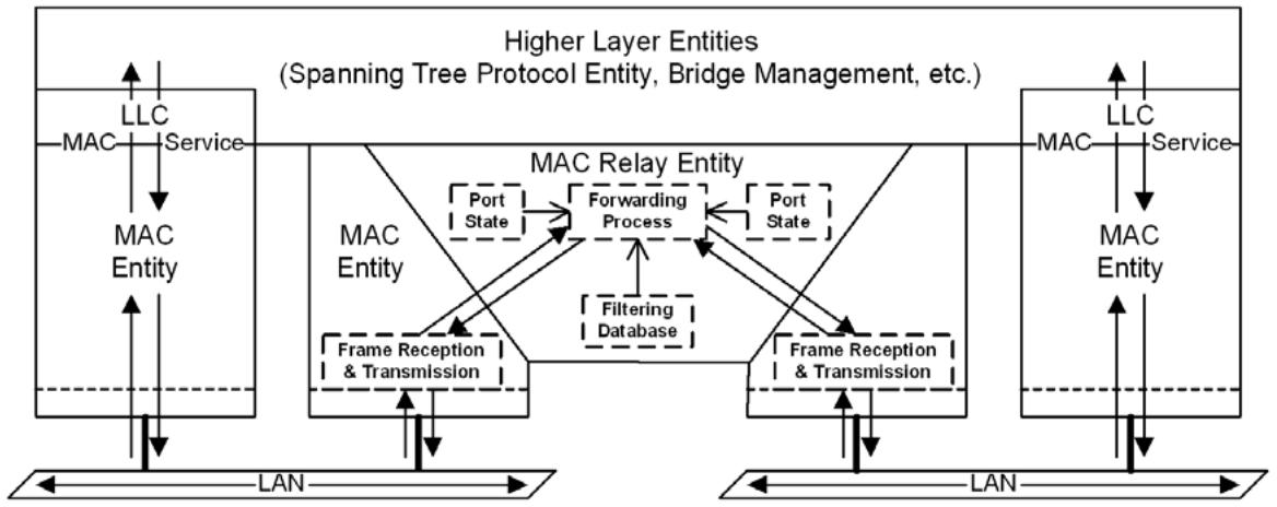
Figure 8-12—Logical points of attachment of the Higher Layer and Relay Entities
Figure 8-13 depicts the information used to control the forwarding of frames from one Bridge Port to another (the Port States and the content of the FDB) as a series of switches (shown in the open, disconnected state) inserted in the path provided by the MAC Relay Entity. For the Bridge to forward a given frame between two Ports, all three switches must be in the closed state. While showing Higher Layer Entities sharing the point of attachment to each LAN used by each Bridge Port to forward frames, this figure further illustrates a point made by Figure 8-12. Controls placed in the forwarding path have no effect on the ability of a Higher Layer Entity to transmit and receive frames to or from a given LAN using a direct attachment to that LAN (e.g., from entity A to LAN A); they only affect the path taken by any indirect transmission or reception (e.g., from entity A to or from LAN B).
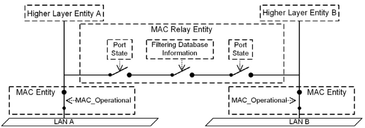
Figure 8-13—Effect of control information on the forwarding path
The functions provided by Higher Layer Entities can be categorized as requiring either
a) A single point of attachment to the Bridged Network, providing connectivity to stations attached to the network at any point (subject to administrative control), as does Bridge Management; or
b) A distinct point of attachment to each individual LAN attached by a Bridge Port, providing connectivity only to peer entities connected directly to that LAN, as do the Spanning Tree Protocol Entity and the MRP entity.
In the latter case, it is essential that the function associate each received and transmitted frame with a point of attachment. Frames transmitted or received via one point of attachment are not to be relayed to and from other Ports and attached LANs, so the MAC addresses (8.13.4) used to reach these functions are permanently configured in the FDB.
NOTE 1 —Addresses used to reach functions with distinct points of attachment are generally group MAC addresses.
NOTE 2—A single higher layer entity can incorporate both a function requiring a single point of attachment and a function requiring distinct points of attachment. The two functions are reached using different MAC addresses.
Figure 8-14 illustrates forwarding path connectivity for frames destined for Higher Layer Entities requiring per-Port points of attachment. Configuration of the Permanent Database in all Bridges to prevent relay of frames addressed to these entities means that they receive frames only via their direct points of attachment (i.e., from LAN A to entity A, and from LAN B to entity B), regardless of Port states.
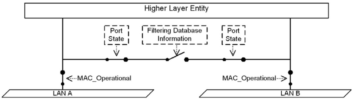
Figure 8-14—Per-Port points of attachment
Figure 8-15 and Figure 8-16 illustrate forwarding path connectivity for frames destined for a Higher Layer Entity requiring a single point of attachment. In both figures, the FDB permits relay of frames, as do the Port states in Figure 8-15 where frames received from LAN B are relayed by the Bridge to the entity and to LAN A.
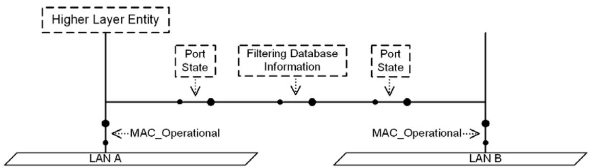
Figure 8-15—Single point of attachment—relay permitted
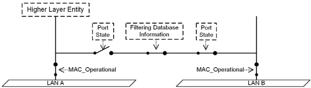
Figure 8-16—Single point of attachment—relay not permitted
In Figure 8-16, frames received from LAN A are received by the entity directly, but frames received from LAN B are not relayed by the Bridge and will only be received by the entity if another forwarding path is provided between LANs A and B. If the Discarding Port state shown resulted from spanning tree computation (and not from disabling the Administrative Bridge Port State), such a path will exist via one or more Bridges. If there is no active spanning tree path from B to A, the network has partitioned into two separate Bridged Networks, and the Higher Layer Entity shown is reachable only via LAN A.
Specific Higher Layer Entities can take notice of the Administrative Bridge Port State, as required by their specification. The Spanning Tree Protocol Entity is one such example—BPDUs are never transmitted or received on Ports with an Administrative Bridge Port State of Disabled.
If a Bridge Port’s MAC Entity is not operational, a Higher Layer Entity directly attached at the Port will not be reachable, as Figure 8-17 illustrates. The Spanning Tree Protocol Entity ensures that the Port State is Discarding if the MAC_Operational (IEEE Std 802.1AC) is FALSE even if the Administrative Bridge Port State is Enabled.
Port-based network access control (IEEE Std 802.1X) and MAC Security (IEEE Std 802.1AE-2006 [B6]) can be used to provide a further level of control over the connectivity provided by a Bridge Port to the MAC Relay Entity and the Higher Layer Entities within a Bridge. Port-based network access control creates two distinct SAPs for the LAN: the Controlled Port and the Uncontrolled Port. MAC_Operational is TRUE for the Controlled Port only when criteria for authentication, authorization, and secure connectivity have been satisfied; while MAC_Operational for the Uncontrolled Port is the same as that for direct access to the LAN.
Figure 8-17—Effect of Port State
Both the Spanning Tree Protocol Entity and the MAC Relay Entity attach to the Controlled Port, thus ensuring that the connectivity seen by each of those entities is the same. If MAC_Operational for the Controlled Port is FALSE, the Spanning Tree Protocol Entity will ensure that both forwarding and learning (8.4) will be FALSE for that Port (i.e., the Port State will be Discarding). The Uncontrolled Port supports the operation of protocol entities such as the Port Access Entity (PAE) specified by IEEE Std 802.1X, that participate in the authentication exchanges necessary before Controlled Port connectivity is permitted or that distribute other unsecured information.
Figure 8-18 illustrates the connectivity provided to Higher Layer Entities if the MAC entity is physically capable of transmitting and receiving frames but MAC_Operational is FALSE for the Controlled Port. Higher Layer Entity A and the PAE are connected to an Uncontrolled Port and can transmit and receive frames using the MAC entity associated with the Port for LAN A, which Higher Layer Entity B cannot. None of the three entities can transmit or receive to or from LAN B.
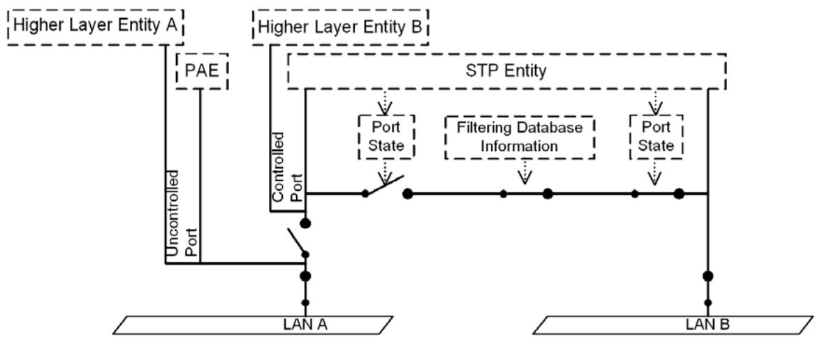
Figure 8-18—Controlled and Uncontrolled Port connectivity
NOTE 3—Reference should be made to IEEE Std 802.1X-2010 or later.
NOTE 4—The administrative and operational state values associated with the MAC, the Port’s authorization state, and the Bridge Port State equate to the ifAdminStatus and ifOperStatus parameters associated with the corresponding interface definitions; see IETF RFC 2863 [B28].
8.13.10 VLAN attachment and connectivity for Higher Layer Entities
In VLAN Bridges, two more switches appear in the forwarding path, corresponding to the actions taken by the Forwarding Process (8.6) in applying the ingress and egress rules (8.6.2 and 8.6.4), as illustrated in Figure 8-19.
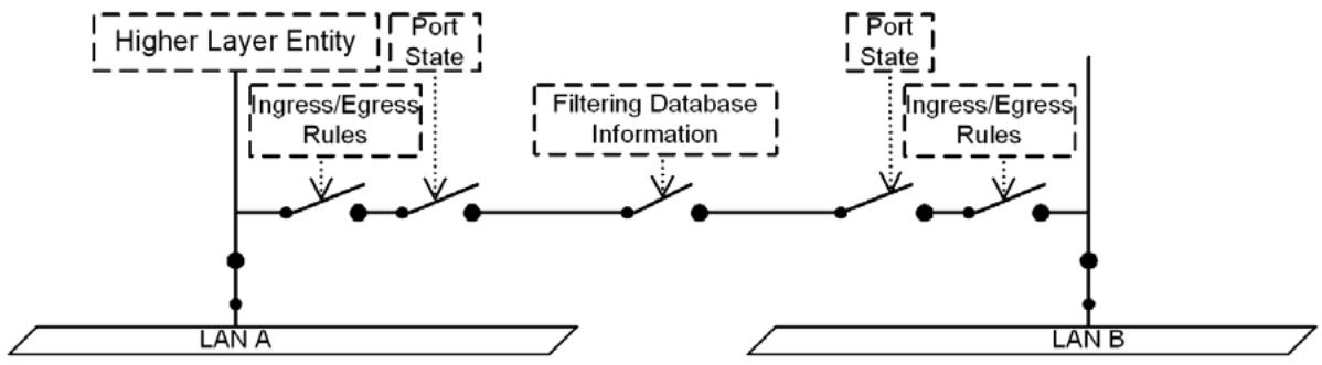
Figure 8-19—Ingress/egress control information in the forwarding path
As with Port state information, the configuration of the ingress and egress rules does not affect the reception of frames received on the same LAN as a Higher Layer Entity’s point of attachment. For example, the reception of a frame by Higher Layer Entity A that was transmitted on LAN A is unaffected by the ingress or egress configuration of either Port. However, for Higher Layer Entities that require only a single point of attachment, the ingress and egress configuration affects the forwarding path. For example, frames destined for Higher Layer Entity A that are transmitted on LAN B would be subjected to the ingress rules that apply to Port B and the egress rules that apply to Port A.
The decision about whether frames transmitted by Higher Layer Entities are VLAN-tagged or untagged depends on the Higher Layer Entity concerned and the connectivity that it requires:
a) Spanning Tree Bridge Protocol Data Units (ST BPDUs) transmitted by the Spanning Tree Protocol Entity are not forwarded by Bridges and must be visible to all other Spanning Tree Protocol Entities attached to the same LAN. Such frames shall be transmitted untagged;
NOTE—Any BPDUs or MVRPDUs that carry a tag header are not recognized as well-formed BPDUs or MVRPDUs and are not forwarded by the Bridge.
b) The definition of the MVRP application (11.2.3) calls for all MVRP frames to be transmitted untagged for similar reasons;
c) The definition of the MMRP application (Clause 10) calls for all MMRP frames originating from VLAN devices to be transmitted VLAN-tagged, in order for the VID in the tag to be used to identify the VLAN context in which the registration applies;
d) It may be necessary for PDUs transmitted for Bridge Management (8.12) to be VLAN-tagged in order to achieve the necessary connectivity for management in a Virtual Bridged Network. This is normally achieved by routing a packet containing the PDU to the routed subnet associated with the VLAN. Transmission of the packet through the router interface to that VLAN and subsequent forwarding of the resulting frame by VLAN Bridges ensures that the frame is correctly VLANtagged, as required.
8.13.11 CFM entities
CFM entities reside in shims. The entities in a CFM shim inspect every frame that passes through either of the shim’s two SAPs, and decides whether to pass that frame through to the other SAP, process it, or both. The decision whether pass it through is not dependent on the destination_address, but the decision whether to process the frame is dependent on the destination_address (see Clause 19). A CFM entity shall discard any frame, directed to it by reason of its VID and MD Level, whose destination_address parameter does not correspond to a MAC address recognized by that CFM entity.
Any given CFM entity is configured to recognize one or more individual MAC addresses, and one or more group MAC addresses, in received frames, and to use one or more individual MAC address or one or more group MAC addresses for transmitted frames. The individual MAC address is unique, within a bridged network, to a specific Bridge, though not necessarily to a single Bridge Port (J.6). For VLAN-based and backbone service instances, the group MAC addresses are selected from Table 8-15 and Table 8-16 according to the MD Level and OpCode fields in the CFM PDU header. For these service instances, Loopback Messages (LBMs, 20.2), Loopback Replies (LBRs, 20.2), and Linktrace Replies (LTRs, 20.3) are carried in unicast frames while Continuity Check Messages (CCMs, 20.1) use addresses from Table 8-15, and Linktrace Messages (LTMs, 20.3) use addresses from Table 8-16. In the case of TESI, all CFM messages use the individual MAC addresses or the group MAC addresses that are associated with the monitored service (20.1, 20.2, 20.3).
Table 8-15—CCM group destination MAC addresses
<table><tr><td colspan="2">01-80-C2-00-00-3y</td></tr><tr><td>MD Level of CCM</td><td>Four address bits “y”</td></tr><tr><td>7</td><td>7</td></tr><tr><td>6</td><td>6</td></tr><tr><td>5</td><td>5</td></tr><tr><td>4</td><td>4</td></tr><tr><td>3</td><td>3</td></tr><tr><td>2</td><td>2</td></tr><tr><td>1</td><td>1</td></tr><tr><td>0</td><td>0</td></tr></table>
Table 8-16—LTM group destination MAC addresses
<table><tr><td colspan="2">01-80-C2-00-00-3y</td></tr><tr><td>MD Level of LTM</td><td>Four address bits “y”</td></tr><tr><td>7</td><td>F</td></tr><tr><td>6</td><td>E</td></tr><tr><td>5</td><td>D</td></tr><tr><td>4</td><td>C</td></tr><tr><td>3</td><td>B</td></tr><tr><td>2</td><td>A</td></tr><tr><td>1</td><td>9</td></tr><tr><td>0</td><td>8</td></tr></table>
NOTE—The group destination MAC addresses in Table 8-15 are there primarily to make it possible for Bridges built prior to this standard to process CFM. This restriction on the choice of group destination MAC addresses to be used on a CFM PDU is relaxed for ESP-VIDs. See 22.8.
9 Tagged frame format
This clause specifies the format of the tags added to and removed from user data frames by the tag encoding and decoding functions that support the EISS (6.8, 6.9, 6.10, 6.11) and the Backbone Service Instance Multiplex Entity (6.18). It
a) Reviews the purpose of tagging, and the functionality provided;
b) Specifies generic rules for the representation of tag fields and their encoding in the octets of an MSDU;
c) Specifies a general tag format, comprising a Tag Protocol Identifier (TPID), Tag Control Information (TCI), with additional information as signaled in the TCI, and
d) Specifies the format of the TPID for each IEEE 802 media access control method;
e) Describes the types of tags that can be used, including the following:
1) A C-TAG used at ports on a C-VLAN component,
2) An S-TAG used at ports on an S-VLAN component,
3) An I-TAG used at PIPs on an I-component and CBPs on a B-component;
f) Documents the allocation of EtherType values to identify the types of tag specified in this standard;
g) Specifies the format of the TCI and additional information for each tag type.
Further analysis of the frame formats and the format translations that can occur when frames are tagged or untagged when relayed between different media access control methods can be found in Annex G.
9.1 Purpose of tagging
Tagging a frame with a VLAN tag:
a) Allows a VID to be conveyed, facilitating consistent VLAN classification of the frame throughout the network and enabling segregation of frames assigned to different VIDs;
b) Allows priority (IEEE Std 802.1AC, 6.8) to be conveyed with the frame when using IEEE 802 LAN media access control methods that provide no inherent capability to signal priority;
9.2 Representation and encoding of tag fields
In this subclause, octets are numbered starting from 1 and increasing in the order in which they are encoded in the sequence of octets that constitute an MSDU.
Where bits in consecutive octets are used to encode a binary number in a single field, the lower octet number encodes the more significant bits of the field, and the LSB of the lower octet number and the most significant bit (MSB) of the next octet both form part of the field.
Where the value of a field comprising a sequence of octets is represented as a sequence of two-digit hexadecimal values separated by hyphens (e.g., A1-5B-03), the leftmost hexadecimal value (A1 in this example) appears in the lowest numbered octet of the field and the rightmost hexadecimal value (03 in this example) appears in the highest numbered octet of the field.
The bits in an octet are numbered from 1 to 8, where 1 is the LSB.
When the terms set and reset are used in the text to indicate the values of single-bit fields, set is encoded as a binary 1 and reset as a binary 0 (zero).
When the encoding of a field or a number of fields is represented using a diagram:
a) Octets are shown with the lowest numbered octet nearest the top of the page, the octet numbering increasing from the top to bottom; or
b) Octets are shown with the lowest numbered octet nearest the left of the page, the octet numbering increasing from left to right;
c) Within an octet, bits are shown with bit 8 to the left and bit 1 to the right.
9.3 Tag format
Each tag comprises the following sequential information elements:
a) A Tag Protocol Identifier (TPID) (9.4);
b) Tag Control Information (TCI) that is dependent on the tag type (9.5, 9.6);
c) Additional information, if and as required by the tag type and TCI.
The tag encoding function supports each EISS (6.8) instance by using an instance of the ISS to transmit and receive frames and encodes the above information in the first and subsequent octets of the MSDU that will accompany an ISS M_UNITDATA.request, immediately prior to encoding the sequence of octets that constitute the corresponding EISS M_UNITDATA.request’s MSDU. On reception the tag decoding function is selected by the TPID and decodes the TCI and additional information octets (if present) prior to issuing an EISS M_UNITDATA.indication with an MSDU that comprises the subsequent octets.
9.4 TPID formats
The TPID includes an EtherType value that is used to identify the frame as a tagged frame and to select the correct tag decoding functions. Such an EtherType is known as the Tag EtherType.
Where the ISS instance used to transmit and receive tagged frames is provided by a media access control method that can support EtherType encoding directly (e.g., is an IEEE 802.3 MAC) or is media access method independent (e.g., 6.8), the TPID is EtherType encoded, i.e., is two octets in length and comprises solely the assigned EtherType value.
Where the ISS instance is provided by a media access method that cannot directly support EtherType encoding (e.g., is an IEEE 802.11 MAC), the TPID is encoded according to the rule for a Subnetwork Access Protocol (Clause 9 of IEEE Std 802-2014) that encapsulates Ethernet frames over LLC, and comprises the SNAP header (AA-AA-03) followed by the SNAP PID (00-00-00) followed by the two octets of the assigned EtherType value.
9.5 Tag Protocol identification
The following types of tags are specified:
a) A C-TAG, for general use by C-VLAN Bridges (5.9) and C-VLAN components of Provider Edge Bridges (5.10.1).
b) An S-TAG, reserved for use by S-VLAN Bridges (5.10), the S-VLAN component of Provider Edge Bridges (5.10.1) and BEBs (5.12), and C-VLAN Bridges signaling priority to a PBN or a PBBN (6.13).
c) An I-TAG, reserved for use by BEBs (5.7, 5.8, 5.12).
NOTE—The S-TAG is identical to the B-TAG (see 25.2).
A distinct EtherType has been allocated (Table 9-1) for use in the TPID field (9.4) of each tag type so they can be distinguished from each other, and from other protocols.
Table 9-1—IEEE 802.1Q EtherType allocations
<table><tr><td>Tag Type</td><td>Name</td><td>Value</td></tr><tr><td>Customer VLAN Tag</td><td>IEEE 802.1Q Tag Protocol EtherType (802.1QTagType)</td><td>81-00</td></tr><tr><td>Service VLAN Tag or Backbone VLAN Tag</td><td>IEEE 802.1Q Service Tag EtherType (802.1QSTagType)</td><td>88-a8</td></tr><tr><td>Backbone Service Instance Tag</td><td>IEEE 802.1Q Backbone Service Instance Tag EtherType (802.1QITagType)</td><td>88-e7</td></tr></table>
9.6 VLAN Tag Control Information (TCI)
The VLAN TCI field (Figure 9-1) is two octets in length and encodes the vlan_identifier, drop_eligible, and priority parameters of the corresponding EISS M_UNITDATA.request as unsigned binary numbers.
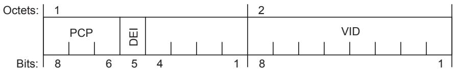
Figure 9-1—VLAN TCI format
The VID is encoded in a 12-bit field. A VLAN Bridge may not support the full range of VID values but shall support the use of all VID values in the range 0 through a maximum N, less than or equal to 4094 and specified for that implementation. Table 9-2 identifies VID values that have specific meanings or uses.
Table 9-2—Reserved VID values
<table><tr><td>VID value (hexadecimal)</td><td>Meaning/Use</td></tr><tr><td>0</td><td>The null VID. Indicates that the tag header contains only priority information; no VID is present in the frame. This VID value shall not be configured as a PVID or a member of a VID Set, or configured in any FDB entry, or used in any Management operation.</td></tr><tr><td>1</td><td>The default PVID value used for classifying frames on ingress through a Bridge Port. The PVID value of a Port can be changed by management.</td></tr><tr><td>2</td><td>The default SR_PVID value used for SRP (35.2.1.4(i)) Stream related traffic. The SR_PVID value of a Port can be changed by management.</td></tr><tr><td>FFF</td><td>Reserved for implementation use. This VID value shall not be configured as a PVID or a member of a VID Set, or transmitted in a tag header. This VID value may be used to indicate a wildcard match for the VID in management operations or FDB entries.</td></tr></table>
NOTE 1—There is a distinction between the range of VIDs that an implementation can support and the maximum number of active VIDs supported at any one time. An implementation supports only 16 active VIDs, for example, may use VIDs chosen from anywhere in the identifier space, or from a limited range. The latter can result in difficulties where different Bridges in the same network support different maximums. It is recommended that new implementations of this standard support the full range of VIDs, even if the number of active VIDs is limited.
The priority and drop_eligible parameters are conveyed in the 3-bit PCP field and the DEI field as specified in 6.9.3.
NOTE 2—Previous versions of this standard used bit 5 of octet 1 of the TCI in C-TAGs as a Canonical Format Indicator (CFI). Bridges conformant to this version of the standard will not interoperate with Bridges that set the CFI as a result of inserting C-TAGs in frames received from an 802.5 Token Ring LAN. Bridges conformant to this version of the standard will interoperate with Bridges that forward bit 5 of octet 1 as a CFI but do not have 802.5 Token Ring interfaces.
9.7 Backbone Service Instance Tag Control Information (I-TAG TCI)
The I-TAG TCI field (Figure 9-2) is 16 octets in length and encodes the priority, drop_eligible, destination_address, and source_address parameters of the corresponding service request primitive as unsigned binary numbers. I-TAGs are encoded and decoded at PIPs and CBPs of BEBs as specified in 6.10, 6.11, and 6.18.
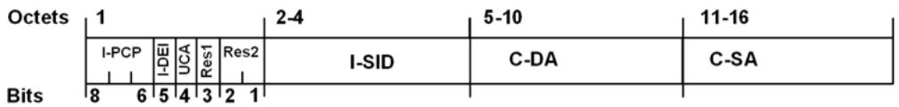
Figure 9-2—I-TAG TCI format
The I-TAG TCI contains the following fields:
a) I-PCP (Priority Code Point)—This 3-bit field encodes the priority and drop_eligible parameters of the service request primitive associated with this frame using the same encoding as specified for VLAN tags in 6.9.3. The PBBN operates on the priority associated with the B-TAG.
b) I-DEI (Drop Eligible Indicator)—This 1-bit field carries the drop_eligible parameter of the service request primitive associated with this frame. The PBBN operates on the drop eligibility associated with the B-TAG.
c) UCA (Use Customer Addresses)—A single-bit flag that, when containing a value of one, signals a Backbone Service Instance Multiplex Entity (6.18) to use the addresses contained in the C-DA and C-SA fields.
d) Res1 (Reserved 1)—This 1-bit field is used for any future format variations. The Res1 field contains a value of zero when the tag is encoded, and is ignored when the tag is decoded.
e) Res2 (Reserved 2)—This 2-bit field is used for any future format variations. The Res2 field contains a value of zero when the tag is encoded. The frame will be discarded if this field contains a nonzero value when the tag is decoded.
f) I-SID (Backbone Service Instance Identifier)—This 24-bit field carries the identifier of the backbone service instance.
g) C-DA (Encapsulated Customer Destination MAC address)—Contains the address in the destination_address parameter of the service request primitive associated with this frame. The address is represented using the Hexadecimal Representation as specified in IEEE Std 802 with the octet containing the I/G bit in the lowest numbered octet of the field.
h) C-SA (Encapsulated Customer Source MAC address)—Contains the address in the source_address parameter of the service request primitive associated with this frame. The address is represented using the Hexadecimal Representation as specified in IEEE Std 802 with the octet containing the I/G bit in the lowest numbered octet of the field.
The I-SID is encoded in a 24-bit field. Table 9-3 identifies I-SID values that have specific meanings or uses.
Table 9-3—Reserved I-SID values
<table><tr><td>I-SID value (hexadecimal)</td><td>Meaning/Use</td></tr><tr><td>0</td><td>Reserved for implementation use. This I-SID value shall not be configured as an identifier for a backbone service instance or transmitted in an I-TAG header. This I-SID value may be used in management and control operations, e.g., to indicate a deleted or null I-SID in ISIS-SPB TLVs (see Clause 28).</td></tr><tr><td>1</td><td>Default value—Unassigned ISID on a VIP.</td></tr><tr><td>2 through FE</td><td>Reserved for use by future amendments to this standard.</td></tr><tr><td>FF</td><td>SPBM default I-SID</td></tr><tr><td>FFFFFF</td><td>Reserved for implementation use. This I-SID value shall not be configured as an identifier for a backbone service instance or transmitted in an I-TAG header. This I-SID value may be used to indicate a wildcard match for the I-SID in management operations.</td></tr></table>
NOTE—There is a distinction between the range of I-SIDs that an implementation can support, and the maximum number of active backbone service instances supported at any one time. An implementation that supports only $2 ^ { 1 6 }$ active backbone service instances, for example, may use I-SIDs chosen from anywhere in the identifier space. Implementations of this standard support the full range of $\mathrm { \cdot _ { I - S i D s , } }$ even if the number of active backbone service instances is limited.
10 Multiple Registration Protocol (MRP) and Multiple MAC Registration Protocol (MMRP)
The Multiple Registration Protocol allows participants in an MRP application to register attributes with other participants in a Bridged Network. The definition of attribute types, their values, and the semantics associated with values when registered, are specific to each MRP application.
This clause
a) Provides an overview of the use of MRP within a bridged network (10.1)
b) Describes the architecture of MRP participants for end stations and Bridge Ports (10.2)
c) Specifies registration propagation between the per-Port Participants in a Bridge (10.3)
d) Details requirements to be met by the MRP design (10.4)
e) Details requirements for interoperability between MRP participants (10.5)
f) Provides an overview of protocol operation (10.6)
g) Provides a detailed specification of the protocol (10.7)
h) Describes the structure of PDUs exchanged between MRP participants (10.8)
Subclauses 10.9 through 10.12 define an MRP application, the Multiple MAC Registration Protocol (MMRP), that registers attributes of two types—MAC addresses and Group service requirements. Values of these attributes control MAC address filtering by MMRP participants.
Clause 11 defines a second MRP application, the Multiple VLAN Registration Protocol (MVRP), that registers VLAN membership information.
Clause 35 defines a third MRP application, the Multiple Stream Registration Protocol (MSRP), that registers data Stream characteristics and reserves Bridge resources as appropriate to provide QoS guarantees.
Clause 39 defines a fourth MRP application, the Multiple I-SID Registration Protocol (MIRP), that serves as an alternative to MVRP for per-VLAN flushing of learned MAC address information in I-components.
10.1 MRP overview
MRP allows a participant in a given MRP application to make or withdraw declarations of attributes, and for those declarations (or withdrawals) to result in the registration (or removal of registrations) of those attributes with the other MRP Participants for that application.
A declaration by an MRP Participant for an end station or Bridge Port is recorded by an Applicant state machine for the declared attribute and Port. Changes in the Applicant state machine’s variables trigger the transmission of MRPDUs to communicate the declaration (or withdrawal).
A registration is recorded by a Registrar state machine for the attribute at each participating end station and Bridge Port that receives the MRPDU. Removal of a given attribute registration occurs only if all the other participants connected to the same LAN withdraw the declaration.
Attributes registered on Bridge Ports that are part of the applicable active topology (8.4, 10.3.1) are declared on all the other Bridge Ports that are also part of that active topology. Hence, a given declaration is propagated to all application participants, and registered in each Bridge on those Ports that are “nearest” to the source or sources of the declaration within the active topology.
Figure 10-1 illustrates the result of a single end station making a declaration, and shows the Bridge Ports that also make declarations to propagate the attribute. The attribute is propagated to all LANs in the Bridged Network, but the directional nature of the propagation results in registration only on Bridge Ports that receive (as opposed to transmit) declarations.
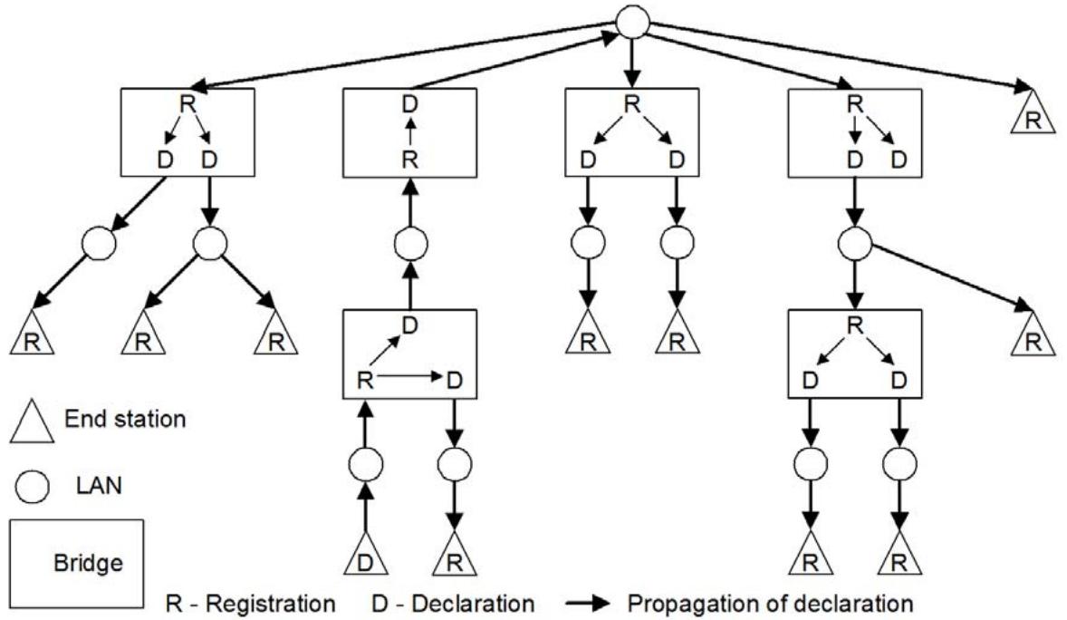
Figure 10-1—Example—Attribute value propagation from one station
NOTE—Unless otherwise stated, the following description assumes operation within the Base Spanning Tree Context (see 10.3.1). While registration can occur on any Bridge Port, regardless of Port State (8.4), propagation follows the spanning tree active topology. All the Bridge Ports shown in Figure 10-1, Figure 10-2, and Figure 10-3 are in the Forwarding Port State.
Figure 10-2 illustrates the result of different end stations declaring the same attribute on different LANs. All end stations register the attribute, and some Bridges register it on more than one Port.
The set of Bridge Ports and end stations that both declare and register a given attribute defines the subset of the active topology that contains all the participants declaring that attribute. A registration can be regarded as a pointer to participants that have declared that attribute, as illustrated in Figure 10-3 (using the same set of declarations and registrations that were illustrated in Figure 10-2).
Situations where it is desirable to form “reachability trees” are generally good candidates for the use of MRP. For example, if the attribute in Figure 10-3 is a group MAC address that is used as a destination address for a video data stream, and it is deemed desirable for that video data to be sent only to the subset of the active topology that contains end stations that have declared that attribute, then an end station that is the source of that video stream could use the presence or absence of a registration as an indication of whether to send the data on the LAN to which it is attached. Any Bridge receiving the data could determine on which Ports the data should be forwarded.
VLAN Bridges that do not support MRP are transparent to MRP exchanges, and forward received MRPDUs on all Ports that are in Forwarding. Similarly, VLAN Bridges that do not implement a given MRP application are transparent to MRP exchanges destined for that application, and forward any such received MRPDUs on all Ports that are in Forwarding.
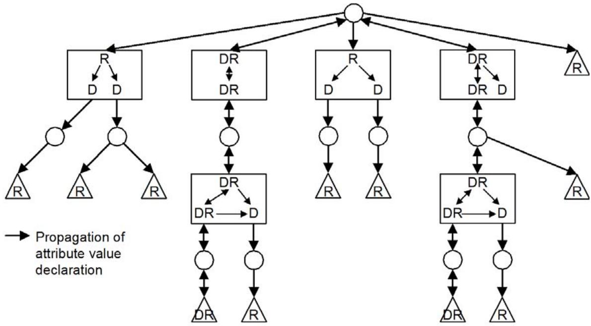
Figure 10-2—Example—Attribute value propagation from two stations
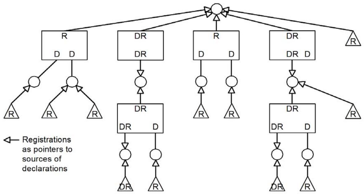
Figure 10-3—Example—Registrations as pointers to the sources of declarations
MRP operates only on Ports that are MAC_Operational (IEEE Std 802.1AC). If the Port is operating as a network access port (IEEE Std 802.1X), MRP uses the controlled port (8.13.9). On any Port whose MAC_Operational parameter is FALSE, any MRP entity shall not transmit MRPDUs, and shall discard, without processing, any received MRPDUs.
MRP provides a means to mark initial attribute declarations and propagated attribute declarations as “new,” signaling to the recipient of the declaration that the attribute value is being newly declared, or is being redeclared following a change in the underlying topology. The rules applied to the marking and propagation of newly declared values in this way are common to all MRP Applications; however, the action taken on receipt of an attribute declaration marked as “new” is specific to each MRP Application. For example, MMRP (10.9) makes no use of the “new” marking, whereas MVRP (Clause 11) uses the “new” marking to permit FDB entries to be flushed on a per-VID basis following a topology change.
10.2 MRP architecture
An MRP Participant consists of an application component, and an MRP Attribute Declaration (MAD) component. The application component is responsible for the semantics associated with attribute values and their registration, including the use of explicitly signaled new declarations, and uses the following two primitives to request MAD to make or withdraw attribute declarations:
MAD_Join.request (attribute_type, attribute_value, new)
MAD_Leave.request (attribute_type, attribute_value)
where attribute_type specifies the type of the attribute declaration, and attribute_value specifies the instance of that type, and the Boolean new parameter indicates an explicit new declaration. If the value of tcDetected (13.25) for the Port and MAP Context associated with the MRP Participant is nonzero, then the value of the new parameter in the propagated MAD_Join.request is set TRUE.
The MAD component executes MRP (10.6, 10.7), generating MRP messages for transmission and processing messages received from other Participants, and uses the following two primitives to notify its application component of a change in Attribute registration:
MAD_Join.indication (attribute_type, attribute_value, new)
MAD_Leave.indication (attribute_type, attribute_value)
One such Participant, per MRP application, exists for each point of attachment to a LAN where Attributes for that application are to be declared or registered, i.e., one Participant per application in an end station, and one per application per Port in a Bridge. The encoding of Attribute values in MRPDUs and their subsequent decoding is application specific, within the general structure specified in 10.8, and each MRPDU conveys messages generated by the MAD component for a single application.
Within a Bridge, a per application MRP Attribute Propagation (MAP) component (10.3) propagates information between the per-Port Participants, using the same request and indication primitives.
Figure 10-4 illustrates the components of MRP Participants in a two-Port Bridge and an end station.
For each MRP application, the following are defined:
a) A set of Attribute types used by the application.
b) The Attribute values permitted for each Attribute type.
c) The semantics associated with each Attribute type and value.
d) The use made of MAP Contexts by the application.
e) The group MAC address and EtherType for protocol exchanges between application Participants.
f) The structure and encoding of the Attribute types and values in MRPDUs.
g) The requirements for MRP state machine support in end stations and Bridges.
h) The circumstances, if any, in which the application makes use of the “new” declaration capability.
NOTE 1—Not all applications of MRP will make use of the “new” declaration capability.
i) If the application makes use of the “new” declaration capability, the semantics that new registrations carry in that application.
j) The number of attribute values out of the possible range of values for which the application is expected to be capable of maintaining current state information.
NOTE 2—In some applications, such as MVRP, the failure of one Bridge in a network to maintain state for all possible attribute values would have major consequences for the integrity of the network. For such applications, the application definition will mandate the ability to track the state of all possible attribute values.
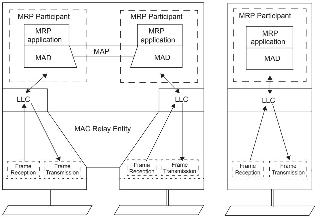
Figure 10-4—MRP architecture
10.3 MRP Attribute Propagation (MAP)
The MAP function enables propagation of attributes registered on Bridge Ports across the network to other participants. Each MRP application specifies the operation of the MAP function. This subclause specifies the operation of the MAP function for the MMRP application, the MVRP application (11.2.1), and the MSRP application (35.2). In addition, 35.2.4 specifies additional MSRP attribute processing rules that modify the MAP function defined below.
For a given MRP application and MAP Context (10.3.1), and for the set of Ports that are in a Forwarding state as defined by that MAP Context, and for the set of attributes associated with that MAP Context:
a) Any MAD_Join.indication, or any MAD_Join.request issued by the MRP application, received by MAP from a given Port in the set is propagated as a MAD_Join.request to the instance(s) of MAD associated with each other Port in the set. If the value of tcDetected (13.25) for the given Port and MAP Context is nonzero, then the value of the new parameter in the propagated MAD_Join.request is set TRUE, regardless of the value of this parameter in the indication or request that is being propagated.
b) Any MAD_Leave.indication, or any MAD_Leave.request issued by the MRP application, received by MAP from a given Port in the set is propagated as a MAD_Leave.request to the instance(s) of
MAD associated with each other Port in the set (Port P, say) if and only if no registration now exists for that Attribute on any other Port in the set excluding P.
These rules propagate attribute registrations through any given Port if any other Port has seen a registration for that attribute, and propagate deregistrations if all other Ports are now deregistered.
As the set of Ports that are in a Forwarding state for a given MAP Context can change dynamically, for example as a result of spanning tree reconfiguration, MAP operates as follows after such a change:
c) If a Port is added to the set, and that Port has registered an attribute (i.e., a MAD_Join.indication or MAD_Join.request has occurred more recently than any MAD_Leave.indication or MAD_Leave.request for the attribute), then MAD_Join.requests are propagated to the MAD instances for each of the other Ports in the set.
d) If a Port is added to the set, but that Port has not declared an attribute that other Ports in the set have registered, then MAD_Join.requests are propagated by those other Ports to the MAD instance for that Port.
e) If a Port is removed from the set, and that Port has registered an attribute and no other Port has, then MAD_Leave.requests are propagated to the MAD instances for each of the other Ports in the set.
NOTE—If a Port is removed from the set, and that Port has declared one or more attributes, then this Port transmits a Leave message (see 10.6) for every attribute that it has declared.
f) If a Port is removed from the set, and that Port has registered an attribute that another Port has also registered, then a MAD_Leave.request is propagated to the MAD instance for that other Port.
10.3.1 MAP Context
For a given Port of an MRP-aware Bridge and MRP application supported by that Bridge, an instance of an MRP Participant can exist for each MRP Attribute Propagation Context (MAP Context) understood by the Bridge. A MAP Context identifies the set of Bridge Ports that form the applicable active topology (8.4).
Examples of MAP Contexts are as follows:
a) The active topology formed by the operation of RSTP (Clause 13). This MAP Context provides the same connectivity as the spanning tree in each Bridge and is known as the Base Spanning Tree Context.
b) The active topology formed by the subset of Bridge Ports, and the underlying spanning tree, that support a given VID. This MAP Context is known as a VLAN Context.
NOTE—This standard uses the Base Spanning Tree Context and VLAN Contexts to define the operation of MMRP and MVRP; however, other MAP Contexts may be used for other applications, or for extending MMRP functionality.
MRP exchanges can occur on all of the Ports of a Bridge; however propagation across a Bridged Network of attribute registrations for a given application uses only those Bridge Ports that are part of the active topology identified by the MAP Context. Each MRP application specification identifies the contexts it can operate within, specifies rules for selecting forwarding Ports, and assigns MAP Context identifiers for use in conjunction with the operation of MRP and its administrative controls (10.7.2, 10.7.3).
A MAP Context identifier of 0 always identifies the Base Spanning Tree Context. The MRP application specifies how the MAP Context of each MRPDU is identified if any other context is used.
10.3.1.1 MAD and Port role changes
A spanning tree provides a loop-free active topology connecting all the Bridges and all the LANs in a network. Hence, any Bridge Port that is in a forwarding state connects two otherwise disconnected parts of the topology. Each Alternate Port on a Bridge A (say) connects to a LAN that has a Port of another Bridge with a better priority vector than A can supply; hence, each of A's Alternate Ports is a potential connection to part of the network that is not connected to any of A’s Designated Ports, all LANs and Bridges in any such part having an equal or worse priority vector than A. Therefore, an Alternate Port on A potentially connects to the part of the network connected to by A's Root Port. Since any part of the network is fully connected, in the absence of registration controls, A's Alternate Port will have registered the same attributes as its Root Port.
For implementations running over RSTP or MSTP, this gives rise to the risk of information loops when Port roles change; because of the store and forward nature of attribute propagation and the potentially rapid transitions of Port roles (compared to the relatively slow transitions that occurred with STP), these can arise even when there are no data loops.
To prevent such information loops from occurring, the information held by MAD’s Registrars for a Port (i.e., information registered on a Port as a result of protocol activity on the LAN to which that Port is connected) is discarded whenever the Port transitions from an Alternate port or Root Port role to become a Designated Port. No such discard is needed for changes in the other direction, i.e., changes from Designated Port to Root Port or Alternate Port.
10.4 Requirements to be met by MRP
MRP establishes, maintains, withdraws, and disseminates attribute declarations and registrations among the MRP Participants attached to a single LAN. The protocol meets the following requirements for Applicant and Registrar behavior, error recovery, performance, scalability, compatibility with non-MRP aware devices, and the load imposed on Bridges, end stations, and the network:
a) Participants can issue declarations for MRP application attributes (10.2, 10.3, 10.7.3, and 10.7.7).
b) Participants can withdraw declarations for attributes (10.2, 10.3, 10.7.3, and 10.7.7).
c) Each Bridge propagates declarations to MRP Participants (10.3).
d) MRP Participants can track the current state of declaration and registration of attributes on each Port of the participant device (10.7.7 and 10.7.8).
e) MRP Participants can remove state information relating to attributes that are no longer active within part or all of the network, e.g., as a result of the failure of a participant (10.7.8 and 10.7.9).
f) The latency involved in issuing, propagating, or revoking attribute declarations, is small (i.e., comparable to the frame propagation delay) and increases linearly as a function of the diameter of the network (10.7.7, 10.7.8, and 10.7.9).
g) MRP is resilient in the face of the failure of MRP Participants.
h) MRP is resilient in the face of single packet loss.
i) MRP will operate correctly in networks where
1) All Bridges support both Basic and Extended Filtering Services; or where
2) Some Bridges support only Basic Filtering Services and some both Basic and Extended Filtering Services (10.5, 10.7.7, 10.7.8, and 10.7.9).
j) The communications bandwidth consumed on any particular LAN by Applicants and Registrars in exchanging MRPDUs will be a small percentage of the total available bandwidth, and independent of the total traffic supported by the network. The bandwidth consumed will be a function of the number of attributes registered.
10.5 Requirements for interoperability between MRP Participants
To ensure the interoperability of MRP, the following are required:
a) All MRP applications use a group MAC address as the destination address of MRPDUs, selected in accordance with the stated requirements of the MRP application concerned for the type of Bridge component in which the application is implemented. The addresses used may be taken from the set of addresses specified in Table 10-1, or taken from the set of reserved addresses specified in Table 8-1, Table 8-2, and Table 8-3, or other group MAC addresses, chosen according to the particular properties required by the application concerned.
NOTE 1—The addresses in Table 8-1, Table 8-2, Table 8-3, and Table 10-1 differ from other group MAC addresses in terms of the scope of transmission within a network, as a consequence of the forwarding/filtering decisions that are taken relative to them by different types of Bridge component.
b) Table 10-1 specifies a set of group MAC addresses, some that have been assigned for use by existing applications defined in this standard, and the others reserved for future standards use. Addresses in this set have the property that
1) Where a given address in the set is used by a Bridge component to support an MRP application, frames destined for that address shall not be forwarded by that Bridge component; i.e., a Static Filtering Entry for that address is maintained for that group MAC address in order to prevent the forwarding of frames destined for that address.
2) Where a given address in the set is not used by a Bridge component to support any MRP application, frames destined for that address received on any Port that is part of a given active topology shall be forwarded by that Bridge component on all other Ports that are part of that active topology.
c) The transmission and reception of MRPDUs between MRP Participants, formatted as defined for the application using the generic PDU format defined in 10.8, shall use LLC procedures. Each MRP application uses a unique EtherType value in order to identify the application protocol. Table 10-2 specifies the EtherType values assigned to existing applications.
NOTE 2—For the purposes of this standard, the expression “use LLC procedures” includes making use of the service provided by link layer protocol entities that support protocol discrimination by means of an EtherType value.
d) MRPDUs, i.e., frames with the destination MAC addresses selected as specified in item a) and the EtherType values specified in item c), that are destined for applications supported by a Bridge component, and that are not well formed (i.e., are not structured and encoded as defined in 10.8 and with attribute types and values encoded as defined by the MRP application), shall be discarded on receipt.
Table 10-1—MRP application addresses
<table><tr><td><eq>Assignment^a</eq></td><td>Value</td></tr><tr><td>Customer and Provider Bridge MMRP address</td><td>01-80-C2-00-00-20</td></tr><tr><td>Customer Bridge MVRP address</td><td>01-80-C2-00-00-21</td></tr><tr><td>Reserved</td><td>01-80-C2-00-00-22</td></tr><tr><td>Reserved</td><td>01-80-C2-00-00-23</td></tr><tr><td>Reserved</td><td>01-80-C2-00-00-24</td></tr><tr><td>Reserved</td><td>01-80-C2-00-00-25</td></tr><tr><td>Reserved</td><td>01-80-C2-00-00-26</td></tr><tr><td>Reserved</td><td>01-80-C2-00-00-27</td></tr><tr><td>Reserved</td><td>01-80-C2-00-00-28</td></tr><tr><td>Reserved</td><td>01-80-C2-00-00-29</td></tr><tr><td>Reserved</td><td>01-80-C2-00-00-2A</td></tr><tr><td>Reserved</td><td>01-80-C2-00-00-2B</td></tr><tr><td>Reserved</td><td>01-80-C2-00-00-2C</td></tr><tr><td>Reserved</td><td>01-80-C2-00-00-2D</td></tr><tr><td>All Provider Bridge Intermediate Systems</td><td>01-80-C2-00-00-2E</td></tr><tr><td>All Customer Bridge Intermediate Systems</td><td>01-80-C2-00-00-2F</td></tr></table>
a MIRP is an MRP application, but is not assigned an address from this table (39.2.1.5, 39.2.1.6).
Table 10-2—MRP EtherType values
<table><tr><td>Assignment</td><td>Value</td></tr><tr><td>MMRP EtherType</td><td>88-F6</td></tr><tr><td>MVRP EtherType</td><td>88-F5</td></tr><tr><td>MSRP EtherType</td><td>22-EA</td></tr><tr><td>MIRP EtherType</td><td>89-29</td></tr></table>
10.6 Protocol operation
This subclause provides an informal introduction. The definitive specification of MRP is contained in 10.7 and 10.8.
MRP is a simple, fully distributed, many-to-many protocol, that supports efficient, reliable, and rapid declaration and registration of attributes by multiple participants on shared and virtual shared media. MRP also incorporates optimizations to speed attribute declarations and withdrawals on point-to-point media. Correctness of MRP operation is independent of the relative values of protocol timers, and the protocol design is based primarily on the exchange of idempotent protocol state rather than commands.
A full MRP Participant maintains Registrar and Applicant state machines for each Attribute of interest, and a LeaveAll state machine and PeriodicTransmission state machine for the participant as a whole.
The job of the Registrar is to record declarations of the attribute made by other Participants on the LAN. It does not send any protocol messages, as the Applicant looks after the interests of all would-be Participants.
The job of the Applicant is twofold:
a) To ensure that this Participant’s declaration is correctly registered by other Participants’ Registrars.
b) To prompt other Participants to reregister after one withdraws a declaration.
NOTE 1—Applicant-Only implementations are concerned only with item a).
The basic design of MRP is oriented to LAN environments, where there is generally a low probability of frame loss, and ensures that timely registration of attributes is unaffected unless at least two out of a set of immediately related frames are lost. The LeaveAll state machine periodically ensures that Participants reregister attributes, thus guarding against an extended failure to register or deregister. In potentially lossy environments such as service instances supported by PBNs, where frame losses are temporally correlated, the PeriodicTransmission machine ensures successful registration without immediately contributing to congestive loss.
If one Applicant has both declared and registered an Attribute, other Applicants do not need to reiterate the declaration. MRP messages convey both Applicant and Registrar state to allow suppression of such repeated declarations. The Applicant state machine distinguishes between Active Participants (that have sent a message or messages to make a declaration), Passive Participants (that require registration, but have not had to declare the attribute so far to register it, and will not have to explicitly deregister), and Observers (that do not require registration at present, but track the attribute’s registration in case they do and become Passive Participants). The following four distinct messages communicate the transmitting participant’s state for an Attribute:
Empty—Not declared, and not registered.
In—Not declared, but registered.
JoinEmpty—Declared, but not registered.
JoinIn—Declared and registered.
One message communicates a withdrawal of a prior declaration, so that Registrars do not have to track individual Applicants:
Leave—Previously registered, but now withdrawn.
A further message conveys a declaration from a new Participant, or a Participant newly added to the active topology reached through a Bridge Port. This information is propagated by the MAP component, and so includes additional registrations elsewhere in the bridged network:
New—Newly declared, and possibly not previously registered.
The LeaveAll state machine uses the following single message that applies to all Attributes.
— LeaveAll—All registrations will shortly be deregistered; Participants need to reregister.
The Registrar for each Attribute actually implements the following three states for the Attribute:
IN—Registered.
LV—Previously registered, but now being timed out.
MT—Not registered.
A single timer, the leavetimer, is associated with each Registrar and operates in the LV state. In that state, MRP messages for the Attribute report it as unregistered (using Empty or Join Empty) but the MAD Leave indication is delayed until the leavetimer expires and the state transitions to MT.
NOTE 2—The accuracy required for the leavetimer is sufficiently coarse to permit the use of a single operating system timer per Participant with 2 bits of state for each Registrar.
The Applicant for each Attribute implements states that record whether it wishes to make a new declaration, to maintain or withdraw an existing declaration, or has no declaration to make. It also records whether it has actively made a declaration, or has been passive, taking advantage of or simply observing the declarations of others. It counts the New, JoinIn, and JoinEmpty messages it has sent, and JoinIn messages sent by others, to ensure that at least two such messages have been sent since it last received a LeaveAll or Leave message, and at least one since it last received a JoinEmpty or Empty message. This ensures that each of the other Participant’s Registrars for the Attribute either have received (assuming no packet loss) two Join or New messages or have reported the Attribute as registered. The Applicant state machine (Table 10-3) uses the following states:
VO—Very anxious Observer. The applicant is not declaring the attribute, and has not received a JoinIn message since the state machine was initialized, or since last receiving a Leave or LeaveAll.
VP—Very anxious Passive. The applicant is declaring the attribute, but has neither sent a Join nor received a JoinIn since the state machine was initialized, or since last receiving a LeaveAll or Leave.
VN—Very anxious New. The applicant is declaring the attribute, but has not sent a message since receiving a MAD Join request for a new declaration.
AN—Anxious New. The applicant is declaring the attribute, and has sent a single New message since receiving the MAD Join request for the new declaration.
AA—Anxious Active. The applicant is declaring the attribute, and has sent a Join message, since the last Leave or LeaveAll, but either has not received another JoinIn or In, or has received a subsequent message specifying an Empty registrar state.
QA—Quiet Active. The applicant is declaring the attribute and has sent at least one of the required Join or New messages since the last Leave or LeaveAll, has seen or sent the other, and has received no subsequent messages specifying an Empty registrar state.
LA—Leaving Active. The applicant has sent a Join or New message since last receipt of a Leave or LeaveAll, but has subsequently received a MAD Leave request and has not yet sent a Leave message.
AO—Anxious Observer. The applicant is not declaring the attribute, but has received a JoinIn since last receiving a Leave or LeaveAll.
QO—Quiet Observer. The applicant is not declaring the attribute, but has received two JoinIns since last receiving a Leave or LeaveAll, and at least one since last receiving a message specifying an Empty registrar state.
AP—Anxious Passive. The applicant is declaring the attribute, and has not sent a Join or a New since last receiving a Leave or a LeaveAll but has received messages as for the Anxious Observer state.
QP—Quiet Passive. The applicant is declaring the attribute, and has not sent a Join or a New since last receiving a Leave or a LeaveAll but has received messages as for the Quiet Observer state.
LO—Leaving Observer. The applicant is not declaring the attribute, and has received a Leave or LeaveAll message.
If an Applicant receives a Leave or LeaveAll message it will send a JoinEmpty or Empty message, and that message will prompt any other Applicants that are declaring the attribute to send a JoinIn. An Applicant that sends a LeaveAll message will also ensure that an Empty message is sent to prompt other Applicants to repeat their declaration. Thus, if any Participant’s Registrar deregisters an Attribute, at least two messages will be lost before another Participant’s Applicant fails to make a required redeclaration.
To facilitate and encourage the transmission of timely protocol information and the encoding of messages for multiple Attributes within the same MRPDU, rather than the use and subsequent queuing of multiple PDUs prior to transmission, PDU transmission is specified in terms of requests for a transmission opportunity, and the Applicant and LeaveAll state machines specify the necessary addition of messages to an MRPDU when that opportunity occurs. Whenever a state machine transitions to a state that requires transmission of a message, a transmit opportunity is requested if one is not already pending. The message actually transmitted (if any) is that appropriate to the state of the machine when the opportunity is presented.
NOTE 3—Specifying transmit opportunity requests and their subsequent use is also intended to aid correct implementation in systems where a transmission is not possible immediately, e.g., shortly after whole or part of the system is initialized when other claims on system resources take precedence or interfaces are not yet available.
To support the efficient encoding of many messages in a single MRPDU, the number of message types has been kept to the minimum consistent with protocol goals and requirements, and the state machines specify both whether it is necessary to send a message and a message type that can always be sent—thus removing the need for a further “no message” encoding. The MRPDU structure and compact encoding (10.8) allows all potential attributes for certain MRP applications, e.g., MVRP (Clause 11), to be encoded in a single IEEE 802.3 frame and this further promotes protocol efficiency through ready detection of missing registrations. Protocol efficiency and correct registration are further supported by encoding a LeaveAll message (if required) at the beginning of the MRPDU, and by using an Applicant state machine that minimizes state changes for those Attributes whose redeclaration can be encoded in the same PDU—if the LeaveAll is received by another Participant so also will be the redeclaration, and sequential processing of the encoded messages by the recipient will ensure that the registration is uninterrupted. Applicant states for Attributes that cannot be redeclared in the same PDU allow for receipt of the LeaveAll but loss of the redeclaration.
LeaveAll messages are transmitted to ensure that any failure to withdraw a declaration does not result in an unwanted permanent registration—perhaps the system or process responsible for the registration has been removed from the LAN or has ceased to operate. Attributes registered by the Participant transmitting the LeaveAll as well as those receiving it are therefore timed out. The LeaveAll state machine (10.7.9) for the Participant operates a single timer, the leaveAllTimer, that causes a transmit opportunity to be requested when it expires, and transmission of a LeaveAll at the next opportunity. Reception of a LeaveAll message from another Participant causes the timer to be restarted without generating a message, thus suppressing multiple LeaveAll messages from Participants connected to the same LAN.
NOTE 4—In the face of changing inputs, arbitrary loss, delay, reordering, and unsignaled interruption in participation, no protocol will meet its objectives. What can be said is that the objectives will be met after a known period of operation within specified limits, and what failures are most likely otherwise. MRP favors ensuring that registrations are made, at the expense of tolerating prolonged registrations. Thus, the LeaveAll mechanism, when it has an effect, most often implements “garbage collection.” At the same time it will also ensure that failed registrations are (re-)established.
When MRP Participants are connected by a shared or virtual shared medium, protocol performance is improved and the effect on other protocols using the LAN minimized if the Participants transmit at different times, avoiding a multicast storm and allowing some to optimize their transmissions based on messages received. A request for a transmit opportunity starts a randomized join timer, with a maximum value chosen to ensure successful reregistration(s) within a Leave time period (10.7.4), and the transmit opportunity is offered when the timer expires. If more messages are to be sent than can fit in a single PDU, a further transmit opportunity is requested.
When two MRP Participants are connected by a point-to-point medium or service instance delaying MRPDU transmission provides no benefit. In bridged networks it is desirable to transmit without delay, minimizing the denial of service that might occur while registration changes propagate after reconfiguration, and maximizing the benefit from using protocols such as RSTP and MSTP. When operPointToPointMAC (IEEE Std 802.1AC) is TRUE, transmit opportunities are scheduled immediately on request, subject to rate limiting (10.7.4).
Use of point-to-point service connecting at most two Participants allows further protocol optimization, e.g., receipt of an In message does acknowledge registration. However, not all LAN media support reliable determination of point-to-point status, particularly if nonstandard bridge-like devices are present. When operating in point-to-point mode, MRP avoids behavior that could cause failure, potentially continuous rapid exchanges of messages, or flapping registrations if there are more than two Participants. This standard permits simple point-to-point subset implementations of MRP, but these will successfully operate on shared media—albeit at reduced efficiency.
NOTE 5—IEEE Std 802.1AE-2006 [B6] (MAC Security) can ensure that there are at most two communicating Participants.
In certain contexts, often encountered in PBNs or PBBNs, it is necessary to control the VLAN entries in the FDB using Static VLAN Registration Entries, and retain only the ability to signal the need to flush learned MAC Address Entries via MRP. A New-Only Participant supports this need by implementing only a part of the Applicant and Registrar state machines, but not implementing the LeaveAll state machine, and by transmitting and receiving only New messages. It is also possible to simplify an MRP Participant that only wishes to make declarations; for example, for an end station that uses MMRP (10.9) to declare a need to receive group addressed frames, but is not a source of such frames, and therefore does not need to support source pruning by registering declarations from other Participants. Such an Applicant-Only Participant does not implement the Registrar or LeaveAll state machines, never sends LeaveAll, Empty, or JoinEmpty messages (which would elicit unnecessary Joins from its peer Participants), and does not implement the administrative controls defined in 10.7.2 and 10.7.3. The following five types of MRP implementation conform to this standard:
Full Participant
Full Participant, point-to-point subset
— New-Only Participant
Applicant-Only Participant
— Applicant-Only point-to-point subset, also referred to as the Simple-Applicant Participant
While Simple-Applicant and Full Participant point-to-point subset implementations can operate on shared media, their initial Join and Leave messages are not suppressed. Significant additional, and unnecessary, traffic can result from attaching several such implementations to the same shared medium. Devices that do not perform registration should use an Applicant-Only Participant rather than a Simple-Applicant Participant.
NOTE 6—At the time of the development of this standard the LAN MACs most commonly used were point-to-point but the use of virtual shared media was increasing.
10.7 Protocol specification
The operation of MRP as executed by the MRP Attribute Declaration (MAD, 10.2) component of an MRP Participant is represented by the following state machines:
a) A per-Attribute Applicant state machine (10.7.7)
b) A per-Attribute Registrar state machine (10.7.8)
c) A LeaveAll state machine for the Participant as a whole (10.7.9)
d) A PeriodicTransmission state machine for the Participant as a whole (10.7.10)
These state machines are specified as compact state tables, and make use of the following:
e) Notational conventions and abbreviations for protocol events, actions, and timer operations (10.7.1)
f) Registrar Administrative Controls (10.7.2)
g) Applicant Administrative Controls (10.7.3)
h) Protocol timers (10.7.4)
i) Protocol event definitions (10.7.5)
j) Protocol action definitions (10.7.6)
A Full Participant implements the complete Applicant state machine (Table 10-3) and the Registrar state machine (Table 10-4) for each Attribute declared, registered, or tracked, together with a single instance of the LeaveAll state machine (Table 10-5) and the PeriodicTransmission state machine (Table 10-6).
The point-to-point subset of the Full Participant implements the same state machines, but omits certain Applicant state machine states and actions as specified by Table 10-3.
A New-Only Participant implements the Applicant state machine, with the omission of certain states and actions, as specified in Table 10-3, and the Registrar state machine (Table 10-4), for each Attribute declared, registered, or tracked, but does not implement the LeaveAll state machine (Table 10-5) or the PeriodicTransmission state machine (Table 10-6). Applications that permit both Full Participants and New-Only Participants define managed objects (12.9) to make the selection on a per-Port basis.
An Applicant-Only Participant implements the Applicant state machine, with the omission of certain states and actions as specified by Table 10-3, for each Attribute declared, registered, or tracked, together with a single instance of the PeriodicTransmission state machine (Table 10-6).
The point-to-point subset of the Applicant-Only Participant (the Simple-Applicant Participant) implements the same state machines, but omits certain Applicant state machine states and actions as specified by Table 10-3.
NOTE—Conceptually, per-Attribute state is maintained for all possible values of all Attribute types that are defined for a given application; however, in real implementations of MRP, it is likely that the range of possible Attribute values in some applications will preclude this, and the implementation will limit the state to those Attribute values in which the Participant has an immediate interest, either as a Member or as a likely future Member.
Timer values, their relationships, and default values are described in 10.7.11 and Table 10-7, protocol management statistics accumulated by each MAD component in 10.7.12, and interoperability considerations for potentially misordering networks in 10.7.13.
The encoding of MRP messages in MRPUs is specified in 10.8, which also specifies the parsing and checks applied to received PDUs.
10.7.1 Notational conventions and abbreviations
The following conventions are used in the abbreviations used in this subclause:
rXXX receive PDU XXX
sXXX send PDU XXX
txXXX transmit opportunity
XXX! state machine event
!XXX “Not XXX”; i.e., logical NOT applied to the condition XXX
The following abbreviations are used in the state machine descriptions. For their meaning, see 10.7.5 and 10.7.6.
Protocol events:
Begin! Initialize state machine (10.7.5.1)
New! A new declaration (10.7.5.4)
Join! Declaration without signaling new registration (10.7.5.5)
Lv! Withdraw a declaration (10.7.5.6)
tx! Transmission opportunity without a LeaveAll (10.7.5.7)
txLA! Transmission opportunity with a LeaveAll (10.7.5.8)
txLAF! Transmission opportunity with a LeaveAll, and with no room (Full) (10.7.5.9)
rNew! receive New message (10.7.5.14)
rJoinIn! receive JoinIn message (10.7.5.15)
rIn! receive In message (10.7.5.18)
rJoinMt! receive JoinEmpty message (10.7.5.16)
rMt! receive Empty message (10.7.5.19)
rLv! receive Leave message (10.7.5.17)
rLA! receive a LeaveAll message (10.7.5.20)
Flush! Port role changes from Root Port or Alternate Port to Designated Port (10.7.5.2)
Re-Declare! Port role changes from Designated to Root Port orAlternate Port (10.7.5.3)
periodic! A periodic transmission event occurs (10.7.5.10)
leavetimer! leavetimer has expired (10.7.5.21)
leavealltimer! leavealltimer has expired (10.7.5.22)
periodictimer! periodictimer has expired (10.7.5.23)
Protocol actions:
<table><tr><td>New</td><td>send a New indication to MAP and the MRP application (10.7.6.12)</td></tr><tr><td>Join</td><td>send a Join indication to MAP and the MRP application (10.7.6.13)</td></tr><tr><td>Lv</td><td>send a Lv indication to MAP and the MRP application (10.7.6.14)</td></tr><tr><td>sN</td><td>send a New message (10.7.6.2)</td></tr><tr><td>sJ</td><td>send a JoinIn or JoinMT message (10.7.6.3)</td></tr><tr><td>sL</td><td>send a Lv message (10.7.6.4)</td></tr><tr><td>s</td><td>send an In or an Empty message (10.7.6.5)</td></tr><tr><td>[s]</td><td>send an In or an Empty message, if required for optimization of the encoding (10.7.6.5)</td></tr><tr><td>[sL]</td><td>send a Lv message, if required for optimization of the encoding (10.7.6.4)</td></tr><tr><td>[sJ]</td><td>send a Join message, if required for optimization of the encoding (10.7.6.3)</td></tr><tr><td>sLA</td><td>send a Leave All message (10.7.6.6)</td></tr><tr><td>periodic</td><td>Periodic transmission event (10.7.6.7).</td></tr><tr><td>leavetimer</td><td>Leave period timer (10.7.4.2)</td></tr><tr><td>leavealltimer</td><td>Leave All period timer (10.7.4.3)</td></tr><tr><td>periodictimer</td><td>Periodic Transmission timer (10.7.4.4)</td></tr><tr><td>-x-</td><td>Inapplicable event/state combination. No action or state transition occurs in this case.</td></tr></table>
Timers are used in the state machine descriptions in order to cause actions to be taken after defined time periods have elapsed. The following terminology is used in the state machine descriptions to define timer states and the actions that can be performed upon them:
a) A timer is said to be running if the most recent action to be performed upon it was a start.
b) A running timer is said to have expired when the time period associated with the timer has elapsed since the most recent start action took place.
c) A timer is said to be stopped if it has expired or if the most recent action to be performed upon it was a stop action.
d) A start action sets a stopped timer to the running state, and associates a time period with the timer. This time period supersedes any periods that might have been associated with the timer by previous start events.
e) A stop action sets a timer to the stopped state.
The following abbreviations are used for the state names in the state tables and state diagrams:
Registrar states (see 10.6):
<table><tr><td>IN</td><td>In</td></tr><tr><td>LV</td><td>Leaving</td></tr><tr><td>MT</td><td>Empty</td></tr></table>
Applicant and Simple-Applicant states (see 10.6):
<table><tr><td>VO</td><td>Very anxious Observer</td></tr><tr><td>VP</td><td>Very anxious Passive</td></tr><tr><td>VN</td><td>Very anxious New</td></tr><tr><td>AN</td><td>Anxious New</td></tr><tr><td>AA</td><td>Anxious Active</td></tr><tr><td>QA</td><td>Quiet Active</td></tr><tr><td>LA</td><td>Leaving Active</td></tr><tr><td>AO</td><td>Anxious Observer</td></tr><tr><td>QO</td><td>Quiet Observer</td></tr><tr><td>AP</td><td>Anxious Passive</td></tr><tr><td>QP</td><td>Quiet Passive</td></tr><tr><td>LO</td><td>Leaving Observer</td></tr></table>
10.7.2 Registrar Administrative Controls
Associated with each instance of the Registrar state machines are Registrar Administrative Control parameters. These parameters allow administrative control to be exercised over the registration state of each Attribute value, and hence, via the propagation mechanism provided by MAP, allow control to be exercised over the propagation of declarations.
a) Normal Registration. The Registrar responds to incoming MRP messages as specified by Table 10- 4.
b) Registration Fixed (New ignored). The Registrar ignores all MRP messages, and remains IN (registered).
c) Registration Fixed (New propagated). The Registrar ignores all MRP messages except New, and remains IN (registered).
d) Registration Forbidden. The Registrar ignores all MRP messages, and remains MT (unregistered).
The default value of this parameter is Normal Registration.
If the value of this parameter is Registration Fixed (New ignored) or Registration Fixed (New propagated), In and JoinIn messages are sent. If the value of this parameter is Registration Forbidden, Empty or JoinEmpty messages are sent. If the value of this parameter is Registration Fixed (New propagated), only New messages are accepted.
NOTE—The Registrar Administrative Controls are realized by means of the contents of the Port Map parameters of static entries in the FDB for all MRP applications In the case of MMRP, the static entries concerned are Static Filtering Entries (8.8.1); in the case of MVRP and MIRP, the static entries concerned are Static VLAN Registration Entries (8.8.2). The contents of the Port Map parameters in static entries can be modified by means of the management operations defined in Clause 12. In the absence of such control information for a given attribute, the default value “Normal Registration” is assumed
10.7.3 Applicant Administrative Controls
An overall control parameter for each Applicant state machine, the Applicant Administrative Control, determines whether the Applicant state machine participates in MRP exchanges.
a) Normal Participant. The state machine participates normally in MRP exchanges.
b) New-Only Participant. The state machine sends only New MRP messages.
c) Non-Participant. The state machine does not send any MRP messages.
The default value of this parameter is Normal Participant.
NOTE 1—The Applicant Administrative Control parameters can be modified for any MRP application by means of the management operations defined in Clause 12. In the absence of such information for a given attribute, the default value “Normal Participant” is assumed.
NOTE 2—The Applicant Administrative Control parameters can be set per attribute type (see 12.9.2).
10.7.4 Protocol timers
10.7.4.1 jointimer
The Join Period Timer, jointimer, controls the interval between transmit opportunities that are applied to the Applicant state machine. An instance of this timer is required on a per-Port, per-MRP Participant basis. The value of JoinTime used to initialize this timer is determined in accordance with 10.7.11.
10.7.4.2 leavetimer
The Leave Period Timer, leavetimer, controls the period of time that the Registrar state machine will wait in the LV state before transiting to the MT state. An instance of the timer is required for each state machine that is in the LV state. The Leave Period Timer is set to the value LeaveTime when it is started; LeaveTime is defined in Table 10-7.
10.7.4.3 leavealltimer
The Leave All Period Timer, leavealltimer, controls the frequency with which the LeaveAll state machine generates LeaveAll PDUs. The timer is required on a per-Port, per-MRP Participant basis. The Leave All Period Timer is set to a random value, T, in the range LeaveAllTime $< \mathrm { T } < 1 . 5 ^ { * } \mathrm { I }$ eaveAllTime when it is started. LeaveAllTime is defined in Table 10-7.
10.7.4.4 periodictimer
The Periodic Transmission timer, periodictimer, controls the frequency with which the PeriodicTransmission state machine generates periodic! events. The timer is required on a per-Port basis. The Periodic Transmission timer is set to one second when it is started.
10.7.5 Protocol event definitions
Unless stated otherwise in these event definitions, MRPDU reception in a Bridge can occur through all Ports of a Bridge, and events generated as a result of such reception affect only those state machines that are associated with the Port through which the PDU was received.
10.7.5.1 Begin!
The state machine is initialized or reinitialized.
10.7.5.2 Flush!
A Flush! event signals to the Registrar state machine that there is a need to rapidly deregister information on the Port associated with the state machine as a result of a topology change that has occurred in the network topology that supports the propagation of MRP information. If the network topology is maintained by means of the spanning tree protocol state machines, then, for the set of Registrar state machines associated with a given Port and spanning tree instance, this event is generated when the Port Role changes from either Root Port or Alternate Port to Designated Port.
When a Flush! event occurs for a given Port and spanning tree instance, a leavealltimer! event (10.7.5.22) is also signaled to the LeaveAll state machine for that Port and spanning tree instance.
10.7.5.3 Re-declare!
A Re-declare! event signals to the Applicant and Registrar state machines that there is a need to rapidly redeclare registered information on the Port associated with the state machines as a result of a topology change that has occurred in the network topology that supports the propagation of MRP information. If the network topology is maintained by means of the spanning tree protocol state machines, then, for the set of Applicant and Registrar state machines associated with a given Port and spanning tree instance, this event is generated when the Port Role changes from Designated Port to either Root Port or Alternate Port.
10.7.5.4 New!
A new declaration is made. The event is deemed to have occurred if the MAD Service User issues a MAD_Join.request service primitive for the Attribute instance associated with that state machine, indicating a new declaration.
10.7.5.5 Join!
A declaration is made. The event is deemed to have occurred if the MAD Service User issues a MAD_Join.request service primitive for the Attribute instance associated with that state machine.
10.7.5.6 Lv!
A declaration is withdrawn. The event is deemed to have occurred if the MAD Service User issues a MAD_Leave.request service primitive for the Attribute instance associated with that state machine.
10.7.5.7 tx!
A transmission opportunity occurs, without a LeaveAll being signaled by the LeaveAll state machine.
NOTE—The tx! event is modified by the behavior of the LeaveAll state machine. If the LeaveAll state machine has signaled LeaveAll, then tx! is modified to txLA! (see 10.7.5.8).
10.7.5.8 txLA!
A transmission opportunity occurs, with a LeaveAll being signaled by the LeaveAll state machine.
10.7.5.9 txLAF!
A transmission opportunity occurs, with a LeaveAll being signaled by the LeaveAll state machine, and with no room available in the PDU.
10.7.5.10 periodic!
This event indicates to the Applicant state machine that the timer used to stimulate periodic transmission has expired.
10.7.5.11 periodicEnabled!
This event indicates to the Periodic Transmission state machine that it has been enabled by management action (12.9.3).
10.7.5.12 periodicDisabled!
This event indicates to the Periodic Transmission state machine that it has been disabled by management action (12.9.3).
10.7.5.13 Message reception events
For an instance of the Applicant state machine or the Registrar state machine, a message reception event is deemed to have occurred if an MRPDU (10.8) is received, and the following conditions are true:
a) The PDU was addressed to an MRP application (the MRP application address, Table 10-1, or MIRP address, 39.2.1.6) and had an Ethertype (Table 10-2) in accordance with that of the MRP application associated with the state machine.
b) The PDU contains a Message (10.8.1) in which the Attribute Type is the type associated with the state machine.
c) The Message contains a VectorAttribute (10.8.1.2) where the range defined by the FirstValue and NumberOfValues includes the attribute value associated with the state machine.
The specific type of message reception event is determined by the event value (10.8.2.5) associated with the state machine. The possible message reception event types are specified in 10.7.5.14 through 10.7.5.20.
10.7.5.14 rNew!
For an instance of the Applicant or Registrar state machine, a message reception event (10.7.5.13) occurs, and the event value (10.8.2.5) associated with the state machine specifies the New message.
10.7.5.15 rJoinIn!
For an instance of the Applicant or Registrar state machine, a message reception event (10.7.5.13) occurs, and the event value (10.8.2.5) associated with the state machine specifies the JoinIn message.
10.7.5.16 rJoinMt!
For an instance of the Applicant or Registrar state machine, a message reception event (10.7.5.13) occurs, and the event value (10.8.2.5) associated with the state machine specifies the JoinMt message.
10.7.5.17 rLv!
For an instance of the Applicant or Registrar state machine, a message reception event (10.7.5.13) occurs, and the event value (10.8.2.5) associated with the state machine specifies the Lv message.
10.7.5.18 rIn!
For an instance of the Applicant or Registrar state machine, a message reception event (10.7.5.13) occurs, and the event value (10.8.2.5) associated with the state machine specifies the In message.
10.7.5.19 rMt!
For an instance of the Applicant or Registrar state machine, a message reception event (10.7.5.13) occurs, and the event value (10.8.2.5) associated with the state machine specifies the Mt message.
10.7.5.20 rLA!
For an instance of the Applicant state machine, the Registrar state machine, or the LeaveAll state machine, the rLA! event is deemed to have occurred if either
a) The LeaveAll state machine associated with that instance of the Applicant or Registrar state machine performs the sLA action (10.7.6.6); or
b) An MRPDU (10.8) is received, and the following conditions are true:
1) The PDU’s destination MAC address and EtherType are in accordance with the definition of the MRP application associated with the state machine.
2) The PDU contains a Message (10.8.1) in which the Attribute Type is the type associated with the state machine.
3) The Message contains a LeaveAllEvent (10.8.2.6) that carries the value LeaveAll.
NOTE—The LeaveAll state machine operates on a per-application (not per-Attribute Type) basis, but the LeaveAll message operates on a per-Attribute Type basis. Hence, when the LeaveAll state machine issues a LeaveAll, it must generate a LeaveAll Attribute for each Attribute Type supported by the application concerned.
10.7.5.21 leavetimer!
For an instance of the Registrar state machine, the leavetimer! event is deemed to have occurred when the leavetimer associated with that state machine expires.
10.7.5.22 leavealltimer!
For an instance of the LeaveAll state machine, the leavealltimer! event is deemed to have occurred either when the leavealltimer associated with that state machine expires or when a Flush! event (10.7.5.2) occurs for the Port and spanning tree instance associated with that state machine.
10.7.5.23 periodictimer!
For an instance of the PeriodicTransmission state machine, the periodictimer! event is deemed to have occurred when the periodictimer associated with that state machine expires.
10.7.6 Protocol Action definitions
10.7.6.1 MRPDU transmission actions
Unless stated otherwise in these action definitions, MRPDU transmission as a result of the operation of a state machine in a Bridge occurs only through the Port associated with that state machine. MRPDUs shall be transmitted using the destination MAC address and EtherType value defined by the MRP application associated with the state machine.
When the action specifies the transmission of attribute state information, an MRPDU, formatted as defined in 10.8.1, is transmitted so that
a) The PDU contains a Message (10.8.1.2) that carries an Attribute Type (10.8.2.2) that corresponds to the type of attribute associated with the state machine concerned.
b) The Message contains a VectorAttribute (10.8.2.10) in which the FirstValue (10.8.2.7) and NumberOfValues (10.8.2.8) defines a range of attribute values that includes the attribute value associated with the state machine.
c) The Vector (10.8.2.10) encodes an AttributeEvent value in the vector position corresponding to the attribute value for this state machine. The choice of AttributeEvent value is determined by the specific transmission action, as defined below.
In the case of LeaveAll transmission actions, the LeaveAll event value specified by the transmission action is encoded in the NumberOfValues field of the VectorAttribute.
10.7.6.2 sN
The AttributeEvent value New is encoded in the Vector as specified in 10.7.6.1.
10.7.6.3 sJ, [sJ]
If the Registrar state is IN, then the AttributeEvent value JoinIn is encoded in the Vector as specified in 10.7.6.1.
If the Registrar state is MT or LV, then the AttributeEvent value JoinMt is encoded in the Vector as specified in 10.7.6.1.
NOTE—The [sJ] variant indicates that the action is only necessary in cases where transmitting the value, rather than terminating a vector and starting a new one, makes for more optimal encoding; i.e., transmitting the value is not necessary for correct protocol operation.
10.7.6.4 sL
The AttributeEvent value Lv is encoded in the Vector as specified in 10.7.6.1.
10.7.6.5 s, [s]
If the Registrar state is IN, then the AttributeEvent value In is encoded in the Vector as specified in 10.7.6.1.
If the Registrar state is MT or LV, then the AttributeEvent value Mt is encoded in the Vector as specified in 10.7.6.1.
NOTE—In the [s] variant, this value is transmitted only if its inclusion makes for more optimal encoding; i.e., transmitting the value is not necessary for correct protocol operation.
10.7.6.6 sLA
The LeaveAll event value specified by the transmission action is encoded in the NumberOfValues field of the VectorAttribute as specified in 10.7.6.1.
The sLA action also gives rise to a rLA! event (10.7.5.20) against all instances of the Applicant state machine, or the Registrar state machine, associated with the MRP participant.
10.7.6.7 periodic
Causes a periodic! event (10.7.5.10) against all Applicant state machines associated with the participant.
10.7.6.8 Start leavetimer
Causes leavetimer to be started, in accordance with the definition of the timer in 10.7.4.2.
10.7.6.9 Stop leavetimer
Causes leavetimer to be stopped.
10.7.6.10 Start leavealltimer
Causes leavealltimer to be started, in accordance with the definition of the timer in 10.7.4.3.
10.7.6.11 Start periodictimer
Causes periodictimer to be started, in accordance with the definition of the timer in 10.7.4.4.
10.7.6.12 New
This action causes a MAD_Join.indication primitive to be issued to the MAD Service User, indicating the Attribute instance corresponding to the state machine concerned, with the new parameter set TRUE.
10.7.6.13 Join
This action causes a MAD_Join.indication primitive to be issued to the MAD Service User, indicating the Attribute instance corresponding to the state machine concerned, with the new parameter set FALSE.
10.7.6.14 Lv
This action causes a MAD_Leave.indication primitive to be issued to the MAD Service User, indicating the Attribute instance corresponding to the state machine concerned.
10.7.7 Applicant state machine
A full MRP Participant maintains a single instance of the Applicant state machine (Table 10-3) for each Attribute value for which the Participant needs to maintain state information.
Table 10-3—Applicant state table
<table><tr><td rowspan="2" colspan="2"></td><td colspan="12">STATE</td></tr><tr><td><eq>VO^{11,12}</eq></td><td><eq>VP^6</eq></td><td><eq>VN^{6,12}</eq></td><td><eq>AN^{6,12}</eq></td><td><eq>AA^6</eq></td><td><eq>QA^{12}</eq></td><td><eq>LA^6</eq></td><td><eq>AO^{3,11}</eq></td><td><eq>QO^{3,11}</eq></td><td><eq>AP^{3,6}</eq></td><td><eq>QP^3</eq></td><td><eq>LO^6</eq></td></tr><tr><td rowspan="13">EVENT</td><td>Begin!<eq>^{12}</eq></td><td>—</td><td>VO</td><td>VO</td><td>VO</td><td>VO</td><td>VO</td><td>VO</td><td>VO</td><td>VO</td><td>VO</td><td>VO</td><td>VO</td></tr><tr><td>New!<eq>^{12}</eq></td><td>VN</td><td>VN</td><td>—</td><td>—</td><td>VN</td><td>VN</td><td>VN</td><td>VN</td><td>VN</td><td>VN</td><td>VN</td><td>VN</td></tr><tr><td>Join!</td><td>VP</td><td>—</td><td>—</td><td>—</td><td>—</td><td>—</td><td>AA</td><td>AP</td><td>QP</td><td>—</td><td>—</td><td>VP</td></tr><tr><td>Lv!</td><td>—</td><td>VO</td><td>LA</td><td>LA</td><td>LA</td><td>LA</td><td>—</td><td>—</td><td>—</td><td>AO</td><td>QO</td><td>—</td></tr><tr><td>rNew!</td><td>—</td><td>—</td><td>—</td><td>—</td><td>—</td><td>—</td><td>—</td><td>—</td><td>—</td><td>—</td><td>—</td><td>—</td></tr><tr><td>rJoinIn!</td><td><eq>AO^4</eq></td><td><eq>AP^4</eq></td><td>—</td><td>—</td><td>QA</td><td>—</td><td>—</td><td>QO</td><td>—</td><td>QP</td><td>—</td><td>—</td></tr><tr><td>rIn!</td><td>—</td><td>—</td><td>—</td><td>—</td><td><eq>QA^5</eq></td><td>—</td><td>—</td><td>—</td><td>—</td><td>—</td><td>—</td><td>—</td></tr><tr><td>rJoinMt! || rMt!</td><td>—</td><td>—</td><td>—</td><td>—</td><td>—</td><td>AA</td><td>—</td><td>—</td><td>AO</td><td>—</td><td>AP</td><td>VO</td></tr><tr><td>rLv! || rLA! || Re-declare!</td><td><eq>LO^1</eq></td><td>—</td><td>—</td><td>VN</td><td><eq>VP^9</eq></td><td><eq>VP^9</eq></td><td><eq>—^{10}</eq></td><td><eq>LO^1</eq></td><td><eq>LO^1</eq></td><td>VP</td><td>VP</td><td>—</td></tr><tr><td>periodic!</td><td>—</td><td>—</td><td>—</td><td>—</td><td>—</td><td>AA</td><td>—</td><td>—</td><td>—</td><td>—</td><td>AP</td><td>—</td></tr><tr><td>tx!<eq>^{7,12}</eq></td><td>[s]—</td><td>sJ AA</td><td>sN AN</td><td><eq>sN QA^8</eq></td><td>sJ QA</td><td>[sJ]—</td><td>sL VO</td><td>[s]—</td><td>[s]—</td><td>sJ QA</td><td>[s]—</td><td>s VO</td></tr><tr><td>txLA!<eq>^{2}</eq></td><td>[s]LO</td><td>s AA</td><td>sN AN</td><td>sN QA</td><td>sJ QA</td><td>sJ—</td><td>[s]LO</td><td>[s]LO</td><td>[s]LO</td><td>sJ QA</td><td>sJ QA</td><td>[s]—</td></tr><tr><td>txLAF!<eq>^{2}</eq></td><td>LO</td><td>VP</td><td>VN</td><td>VN</td><td>VP</td><td>VP</td><td>LO</td><td>LO</td><td>LO</td><td>VP</td><td>VP</td><td>—</td></tr></table>
Notes to the table:
1 Applicant-Only participants exclude the LO state, and transition to VO.
2 These events do not occur for Applicant-Only participants.
3 Point-to-point subset participants exclude the AO, QO, AP, and QP states.
4 Ignored (no transition) if point-to-point subset or if operPointToPointMAC is TRUE.
5 Ignored (no transition) if operPointToPointMAC is FALSE. See MRP Design Notes below.
6 Request opportunity to transmit on entry to VN, AN, AA, LA, VP, AP, and LO states.
7 If the MRPDU is full and cannot convey a required message there is no change of state and an additional transmit opportunity is requested if that has not been done already.
8 QA if the Registrar is IN, and AA otherwise. See MRP Design Notes below.
MRP design notes:
5 On shared media the receipt of In does not confirm registration by all Participants, and the In could have been sent by an Applicant-Only participant.
8 Since New messages do not convey registrar state, a Leave could have been received without an Empty or JoinEmpty prompt being sent, the transition to AA guards against loss of that Leave by another Applicant.
9 The design accepts a small possibility of a continued registration (after rLv! if a Lv! occurs before a further Join is sent) in return for not accumulating many Active participants when Join!s and Lv!s are frequent. rLv! processing is deliberately not optimized for point-to-point.
10If a Leave has been received, the Registrar for the transmitting participant is very probably IN, as this Applicant has not yet sent a Leave, so the pending Leave is required. The small savings from avoiding transmission of Leaves pending on receipt of LeaveAlls does not merit distinguishing the rLv! and rLA! cases.
11The VO, AO, and QO states represent states where the attribute is neither being declared by the Participant nor being registered by any other station on the LAN. In implementations where dynamic creation and discarding of state machines is desirable, the state machine can be discarded when in any of these states, pending a future requirement to declare or register that attribute value.
12A New-Only Participant recognizes only the Begin!, New!, and tx! events, and ignores all others, so can only reach the VO, VN, AN, and QA states.
10.7.8 Registrar state machine
A full MRP Participant maintains a single instance of this state machine for each Attribute value that is currently registered, or that the Registrar state machine is in the process of deregistering.
NOTE—As with the Applicant, state information is conceptually maintained for all possible values of all Attribute types that are defined for a given application; however, in real implementations of MRP, it is likely that the range of possible Attribute values in some applications will preclude this, and the implementation will limit the state to those Attribute values in which the Participant has an immediate interest. In the case of simple devices that have no interest in what other Participants have registered, it may be appropriate for that device to ignore Registrar operation altogether.
The detailed operation of this state machine is described in Table 10-4.
Table 10-4—Registrar state table
<table><tr><td rowspan="2" colspan="2"></td><td colspan="3">STATE</td></tr><tr><td>IN</td><td>LV</td><td>MT</td></tr><tr><td rowspan="6">EVENT</td><td>Begin!</td><td>MT</td><td>MT</td><td>MT</td></tr><tr><td>rNew!</td><td>NewIN</td><td>NewStop leavetimerIN</td><td>NewIN</td></tr><tr><td>rJoinIn! ||rJoinMt!</td><td>IN</td><td>Stop leavetimerIN</td><td>JoinIN</td></tr><tr><td>rLv! ||rLA! ||txLA! ||Re-declare!</td><td>Start leavetimerLV</td><td>-x-</td><td>-x-</td></tr><tr><td>Flush!</td><td>LvMT</td><td>LvMT</td><td>MT</td></tr><tr><td>leavetimer!</td><td>-x-</td><td>LvMT</td><td>MT</td></tr></table>
10.7.9 LeaveAll state machine
A single LeaveAll state machine exists for each full MRP Participant. Leave All messages generated by this state machine also generate LeaveAll events against all the Applicant and Registrar state machines associated with that Participant and Port; hence, LeaveAll generation is treated by those state machines in the same way as reception of a LeaveAll message from an external source.
The detailed operation of this state machine is described in Table 10-5.
Table 10-5—LeaveAll state table
<table><tr><td rowspan="2" colspan="2"></td><td colspan="2">STATE</td></tr><tr><td><eq>Active^a</eq></td><td>Passive</td></tr><tr><td rowspan="4">EVENT</td><td>Begin!</td><td>Start leavealltimer Passive</td><td>Start leavealltimer Passive</td></tr><tr><td>tx!</td><td>sLA Passive</td><td>-x-</td></tr><tr><td>rLA!</td><td>Start leavealltimer Passive</td><td>Start leavealltimer Passive</td></tr><tr><td>leavealltimer!</td><td>Start leavealltimer Active</td><td>Start leavealltimer Active</td></tr></table>
a Request opportunity to transmit on entry to the Active state
10.7.10 PeriodicTransmission state machine
A single PeriodicTransmission state machine exists for each Port. Periodic Transmission events are generated on a regular basis, against all Applicant state machines that are associated with that Port.
The detailed operation of this state machine is described in Table 10-6.
Table 10-6—PeriodicTransmission state table
<table><tr><td rowspan="2" colspan="2"></td><td colspan="2">STATE</td></tr><tr><td>Active</td><td>Passive</td></tr><tr><td rowspan="4">EVENT</td><td>Begin!</td><td>Start periodictimer Active</td><td>Start periodictimer Active</td></tr><tr><td>periodicEnabled!</td><td>-x-</td><td>Start periodictimer Active</td></tr><tr><td>periodicDisabled!</td><td>Passive</td><td>-x-</td></tr><tr><td>periodictimer!</td><td>Start periodictimer periodic Active</td><td>-x-</td></tr></table>
10.7.11 Timer values
MRP correctness is not critically dependent on the values of protocol timers. However, the protocol operates more efficiently, and with less likelihood of unwanted deregistrations, if the following relationships are maintained between timer values used by peer Participants:
a) LeaveTime should be at least twice the maximum JoinTime, plus six times the timer resolution, to allow reregistration after a Leave or LeaveAll even if a message is lost.
b) To minimize the volume of rejoining traffic generated following a LeaveAll, the value chosen for LeaveAllTime should be large relative to LeaveTime.
The default timer values (Table 10-7) maintain these relationships. They may be modified on a per-Port basis by means of the management functionality defined in Clause 12.
Table 10-7—MRP timer parameter values
<table><tr><td>Parameter</td><td>Value (centiseconds)</td></tr><tr><td>JoinTime</td><td>20</td></tr><tr><td>LeaveTime</td><td>60–100</td></tr><tr><td>LeaveAllTime</td><td>1000</td></tr></table>
NOTE—The default values for the MRP timers are independent of media access method or data rate. This is a deliberate choice, made in the interests of maximizing the “plug and play” characteristics of the protocol.
Implementation of the timers for MRP shall be based on a timer resolution of 1 centisecond or less.
If operPointToPointMAC (IEEE Std 802.1AC) is TRUE, a request for a transmit opportunity should result in such an opportunity as soon as is practicable, given other system constraints, and shall occur within the value specified for JoinTime subject to not more than three such transmission opportunities occurring in any period of 1.5*JoinTime.
If operPointToPointMAC is FALSE, and there is no pending request, a transmit opportunity shall occur at a time value randomized between 0 and JoinTime seconds. These provisions shall apply even if a point-topoint subset Applicant has been implemented.
10.7.12 Operational reporting and statistics
10.7.12.1 Failure to register
Each MRP Participant maintains a count of the number of times that it has received a registration request, but has failed to register the attribute concerned due to lack of space in the FDB to record the registration. The value of this count may be examined by management (see 12.9.2.1.3).
NOTE—Further action to be taken on such events is a matter for implementation choice.
10.7.12.2 Peer tracking
An implementation may support the ability to record against each Registrar state machine the MAC address of the originator of the MRPDU that caused the most recent state change for that state machine (see 12.9.3.1.3).
10.7.13 Interoperability considerations
Correct operation of MRP for a given MRP application requires that protocol exchanges among a given set of communicating MRP Participants maintain sequentiality; i.e., that Participant A cannot receive MRPDU B (generated as a consequence of Participant B receiving MRPDU A) before Participant A has received MRPDU A. In circumstances where the Participants concerned are all attached to the same LAN, such sequentiality is ensured. However, if a set of MRP Participants communicates via an intervening Bridge that does not implement that MRP application (or does not implement MRP at all), the sequentiality constraints expressed in 8.6.6, 8.6.7, and 8.6.8 are insufficient to guarantee the correct operation of MRP. In order for the correct sequencing of PDUs to be maintained through such a Bridge, the following constraint must be met:
If MRPDU A is received on Port X, and is due to be forwarded on Ports Y and Z, and subsequent to being forwarded on Y, MRPDU B is received on Port Y for forwarding on Port Z, then forwarding of B cannot precede A on Port Z.
NOTE—This expresses a stronger sequencing constraint for multicast frames than is stated in 8.6, but a weaker constraint than was required for conformance to IEEE Std 802.1D, 1993 Edition [B8].
The consequence of failure to meet this constraint is that the users of a given MRP application may experience an increased incidence of loss of registration. Therefore, it is inadvisable to construct LAN configurations involving forwarding of MRPDUs through intervening Bridges if those Bridges do not meet the constraint expressed previously.
10.8 Structure and encoding of Multiple Registration Protocol Data Units (MRPDUs)
This subclause describes the generic structure and encoding of the MRPDUs exchanged between all MRP Participants. The structure and encoding of elements that are specific to the operation of the MRP applications are defined by the applications themselves.
Each MRPDU identifies the MRP application by which it was generated, and to which it is being transmitted. Bridges that receive MRPDUs identified as belonging to an MRP application that they do not support shall forward such PDUs on all other Ports that are in a Forwarding state.
NOTE 1—If MRP is used to support an application that can operate in any MAP Context other than 0 (the Base Spanning Tree Context), the application specification describes how that context is identified in protocol exchanges.
Each MRPDU carries one or more MRP messages, each of which identify one or more MRP events (e.g., Join, Leave, LeaveAll) and the attribute class(es) and value(s) to which each event applies. A given MRP Participant shall process MRPDUs in the order in which they are received, and shall process the MRP Messages in a PDU in the order in which they were put into the Data Link Service Data Unit (DLSDU).
NOTE 2—Any messages generated as a consequence of state machine responses to an sLA action and its associated LeaveAll events will be put into the DLSDU after the LeaveAll message(s), or into a later DLSDU.
10.8.1 Structure
10.8.1.1 Transmission and representation of octets
All MRPDUs consist of an integral number of octets, numbered starting from 1 and increasing in the order that they are put into a DLSDU. The bits in each octet are numbered from 1 to 8, where 1 is the low-order bit.
When consecutive octets are used to represent a binary number, the lower octet number has the most significant value.
When the encoding of (an element of) an MRPDU is represented using a diagram in this clause, the following representations are used:
a) Octet 1 is shown toward the top of the page, higher numbered octets being toward the bottom.
b) Where more than one octet appears on a given line, octets are shown with the lowest numbered octet to the left, higher numbered octets being to the right.
c) Within an octet, bits are shown with bit 8 to the left and bit 1 to the right.
10.8.1.2 Structure definition
MRP makes use of an EtherType value as the means of identifying the MRP application that has transmitted, and that will receive, a given MRPDU. Table 10-2 lists the set of MRP applications that are defined, and the EtherType values that correspond to them.
A protocol version field is included in the structure of the MRPDU, in order to provide the ability to identify future enhancements to MRP applications.
MRPDUs exchanged according to the protocol specified in this clause shall have the following structure:
a) The first octet contains the ProtocolVersion.
Following the Protocol Version are one or more Messages. The last element in the PDU is an EndMark.
c) Each Message consists of an AttributeType, an AttributeLength, and an AttributeList, in that order.
d) An Attribute List consists of one or more VectorAttributes. The last element in the AttributeList is an EndMark.
e) A VectorAttribute consists of a VectorHeader, a FirstValue, and a Vector, in that order. The VectorHeader is able to encode both a LeaveAllEvent and the number of attribute events encoded in the vector.
f) If the end of an MRPDU is encountered before an EndMark is reached, then processing of the PDU is terminated as if an EndMark had been reached.
The following Backus-Naur Form (BNF) productions give the formal description of the MRPDU structure:
MRPDU ::= ProtocolVersion, Message {, Message}, EndMark
ProtocolVersion BYTE ::= Defined by the specific MRP application
Message ::= AttributeType, AttributeLength[, AttributeListLength], AttributeList
AttributeType BYTE ::= Nonzero integer defined by the specific MRP application
AttributeLength BYTE ::= Nonzero integer defined by the specific MRP application
AttributeListLength SHORT ::= Nonzero integer defined by the specific MRP application
AttributeList ::= VectorAttribute {, VectorAttribute}, EndMark
VectorAttribute ::= VectorHeader, FirstValue {, Vector}
VectorHeader SHORT ::= (LeaveAllEvent * 8192) + NumberOfValues
FirstValue ::= Defined by the specific MRP application
Vector ::= ThreePackedEvents {, ThreePackedEvents}
[, FourPackedEvents {, FourPackedEvents}]
ThreePackedEvents BYTE ::= (((((AttributeEvent) *6) + AttributeEvent) *6) + AttributeEvent)
AttributeEvent BYTE ::= New | JoinIn | In | JoinMt | Mt | Lv
FourPackedEvents BYTE ::= ((FourPackedType *64) + (FourPackedType *16)
+ (FourPackedType *4) + FourPackedType)
FourPackedType BYTE ::= Integer defined by the specific MRP application
LeaveAllEvent BYTE ::= NullLeaveAllEvent | LeaveAll
NumberOfValues SHORT ::= Number of events encoded in the vector
EndMark SHORT ::= 0x0000 | End of PDU
NullLeaveAllEvent ::= 0
LeaveAll ::= 1
New ::= 0
JoinIn ::= 1
In ::= 2
JoinMt ::= 3
Mt ::= 4
Lv ::= 5
The parameters carried in MRPDUs, as identified in this structure definition, shall be encoded as specified in 10.8.2.
Figure 10-5 illustrates the structure of the MRPDU and its components.
Octet #
<table><tr><td colspan="2">ProtocolVersion</td><td>Message 1</td><td>...</td><td>Message N</td><td>EndMark</td><td>MRPDU structure</td></tr><tr><td colspan="7">Octet #</td></tr><tr><td>1</td><td>2</td><td colspan="2">3</td><td>5</td><td>N</td><td></td></tr><tr><td colspan="2">AttributeType</td><td colspan="2">AttributeLength</td><td>AttributeListLength</td><td>AttributeList</td><td>Message structure</td></tr><tr><td colspan="7">Octet #</td></tr><tr><td colspan="5">1</td><td>N</td><td></td></tr><tr><td colspan="2">VectorAttribute 1</td><td>...</td><td>VectorAttribute N</td><td colspan="2">EndMark</td><td>Attribute List structure</td></tr><tr><td colspan="7">Octet #</td></tr><tr><td>1</td><td colspan="2">3</td><td>M</td><td colspan="2">N</td><td></td></tr><tr><td colspan="2">VectorHeader</td><td colspan="2">FirstValue</td><td colspan="2">Vector</td><td>VectorAttribute structure</td></tr><tr><td colspan="7">Octet #</td></tr><tr><td colspan="2">1</td><td colspan="5">2</td></tr><tr><td colspan="2">LeaveAllEvent</td><td colspan="4">NumberOfValues (13 bits)</td><td>VectorHeader structure</td></tr></table>
Figure 10-5—Format of the major components of an MRPDU
10.8.2 Encoding of MRPDU parameters
10.8.2.1 Encoding of ProtocolVersion
A ProtocolVersion shall be encoded in a single octet, taken to represent an unsigned binary number. It takes a value that is determined by the application concerned.
NOTE—The handling of protocol version information is defined in 10.8.3.5.
10.8.2.2 Encoding of AttributeType
An AttributeType shall be encoded as a single octet, taken to represent an unsigned binary number. The AttributeType identifies the type of Attribute to which the message applies. The range of values that can be taken by the AttributeType, and the meanings of those values, are defined by the application concerned. The value 0 is reserved, and shall not be used as an AttributeType by any MRP application. MRP applications may otherwise allocate meanings to any set of values of AttributeType in the range 1 through 255.
The definition of AttributeType values in the application associates the following with each AttributeType value defined:
a) The size, in octets, of attribute values, and how they are encoded.
b) Any restrictions that are placed upon the range of attribute values that the vector is permitted to represent.
10.8.2.3 Encoding of AttributeLength
An AttributeLength shall be encoded as a single octet, taken to represent an unsigned binary number. The AttributeLength indicates the length, in octets, of the FirstValue field (10.8.2.7) for the Attribute to which the message applies.
10.8.2.4 Encoding of AttributeListLength
An AttributeListLength shall be encoded as two octets, taken to represent an unsigned binary number. The AttributeListLength indicates the length, in octets, of the AttributeList field for the Attribute to which the message applies. This field is not present in all MRPDUs. Specifically, Multiple MAC Registration Protocol Data Units (MMRPDUs) and Multiple VLAN Registration Protocol Data Units (MVRPDUs) do not use this field, whereas Multiple Stream Protocol Data Units (MSRPDUs) do use this field.
10.8.2.5 Encoding of AttributeEvent
An AttributeEvent shall be encoded as an unsigned decimal number in the range 0 through 5. The permitted values and meanings of the AttributeEvent are as follows:
0: New operator
1: JoinIn operator
2: In operator
3: JoinMt operator
4: Mt operator
5: Lv operator
Further values of AttributeEvent are reserved.
The AttributeEvent is interpreted on receipt as a MAD event to be applied to the state machine for the Attribute defined by the AttributeType and AttributeValue to which the AttributeEvent relates.
10.8.2.6 Encoding of LeaveAllEvent
A LeaveAllEvent shall be encoded as an unsigned binary number. The permitted values and meanings of LeaveAllEvent are as follows:
0: NullLeaveAllEvent operator
1: LeaveAll operator
Further values of LeaveAllEvent are reserved.
The LeaveAllEvent is interpreted on receipt as a MAD Leave All event to be applied to the state machines for all Attributes of the type defined by the AttributeType field.
The value NullLeaveAllEvent signifies that there is no Leave All event to process, and is included purely for encoding efficiency in the vector attribute structures. Receipt of this value does not cause any event to be applied to any state machine.
10.8.2.7 Encoding of FirstValue
A FirstValue is encoded in N octets, taken to be an unsigned binary number, in accordance with the specification for the AttributeType defined by the MRP application concerned. The length, in octets, of the FirstValue field is specified by the value contained in the AttributeLength field (10.8.2.3). When NumberOfValues is greater than one (1) FirstValue is incremented in a way that is defined by each MRP application. For example MMRP simply increments FirstValue by adding the number one (1) to it, whereas MSRP adds one (1) to multiple fields within the FirstValue for each increment. Throughout this specification FirstValue incremented by one is denoted as FirstValue + 1, incrementing by two is denoted as FirstValue + 2, etc.
10.8.2.8 Encoding of VectorHeader
The VectorHeader is used to encode both the value of the LeaveAllEvent (10.8.2.6) and the NumberOfValues, the number of AttributeEvent values encoded in a Vector (10.8.2.10). The VectorHeader is taken to be an unsigned binary number, encoded in two octets, as follows:
a) The value of the LeaveAllEvent is multiplied by 8192.
b) The resulting number is added to NumberOfValues.
The range of values that NumberOfValues can take is restricted, such that the following are true:
c) The size of the Vector that is defined by this number will fit in the available space in the PDU.
d) Incrementing FirstValue the number of times specified in NumberOfValues does not exceed the permitted numeric range of FirstValue as defined for the application concerned.
e) The number of AttributeEvent values does not exceed 8191.
f) If the number of AttributeEvent values is zero, FirstValue is ignored and the value is skipped. However, FirstValue is still present, and of the correct length, in octets, as specified by the AttributeLength field (10.8.2.3) for the Attribute to which the message applies.
g) If LeaveAllEvent is a NullLeaveAllEvent, the number of AttributeEvent values is nonzero.
10.8.2.9 Encoding of EndMark
An EndMark shall be encoded as two octets, taken to represent an unsigned binary number. It takes the numeric value 0.
Further values of EndMark are reserved and shall not be used.
NOTE—As defined by the MRPDU structure definition in 10.8.1, if the end of the MRPDU is encountered, this is taken to be an End Mark from the point of view of processing the PDU contents.
10.8.2.10 Encoding of Vector
10.8.2.10.1 Encoding of Vector ThreePackedEvents
The Vector is encoded as zero or more 8-bit values, each containing a numeric value, ThreePackedEvents, derived from three packed numeric values, each of which represents an AttributeEvent, in the range 0 through 5.
As can be seen from the BNF definition of ThreePackedEvents, each 8-bit value is derived by successively adding an event value and multiplying the result by 6. In order to facilitate the subsequent description, the event values are numbered from first to third, as follows:
The NumberOfValues field in the VectorHeader of the VectorAttribute determines the number of 8-bit ThreePackedEvents values, E, that will be present in the vector; hence E is determined by dividing NumberOfValues by 3 and rounding any noninteger answer up to the nearest larger integer.
The FirstValue field of the VectorAttribute determines which of the originator’s state machines the first AttributeEvent value in the first ThreePackedEvents value relates to. The second AttributeEvent value in the first ThreePackedEvents value corresponds to the state machine identified by (FirstValue + 1), and the third AttributeEvent value in the first ThreePackedEvents value corresponds to the state machine identified by (FirstValue + 2), and so on, through subsequent packed values.
Where the NumberOfValues field carries a value that is not a multiple of 3, there will be either one or two AttributeEvent values packed in the final ThreePackedEvents that are ignored; these values are encoded as the numeric value 0 on transmission and are ignored on receipt.
NOTE—If NumberOfValues is zero, there will be no ThreePackedEvents encoded in the vector.
10.8.2.10.2 Encoding of Vector FourPackedEvents
The Vector is encoded as zero or more 8-bit values, each containing a numeric value, FourPackedEvents, derived from four packed numeric values, each of which represent a FourPackedType, in the range 0 through 3. The FourPackedTypes are defined by each MRP application that uses FourPackedEvents. Note that not all MRP applications use FourPackedEvents.
As can be seen from the BNF definition of FourPackedEvents, each 8-bit value is derived by successively adding a FourPackedType value and multiplying the result by 4. In order to facilitate the subsequent description, the event values are numbered from first to fourth, as follows:
$$
\text { FourPackedEvents BYTE } := ((\text { firstFourPackedType } * 6 4) + (\text { secondFourPackedType } * 1 6) + (\text { thirdFourPackedType } * 4) + (\text { fourthFourPackedType }))
$$
The NumberOfValues field in the VectorHeader of the VectorAttribute determines the number of 8-bit FourPackedEvents values, E, that will be present in the vector; hence E is determined by dividing NumberOfValues by 4 and rounding any noninteger answer up to the nearest larger integer.
The FirstValue field of the VectorAttribute determines which of the originator’s state machines the first FourPackedType value in the first FourPackedEvents value relates to. The second FourPackedType value in the first FourPackedEvents value corresponds to the state machine identified by (FirstValue + 1). The third FourPackedType value in the first FourPackedEvents value corresponds to the state machine identified by (FirstValue + 2), and the fourth FourPackedType value in the first FourPackedEvents value corresponds to the state machine identified by (FirstValue + 3), and so on, through subsequent packed values.
Where the NumberOfValues field carries a value that is not a multiple of 4, there will be one, two or three FourPackedType values packed in the final FourPackedEvent that are ignored; these values are encoded as the numeric value 0 on transmission and are ignored on receipt.
NOTE— If NumberOfValues is zero, there will be no FourPackedEvents encoded in the vector.
10.8.3 Packing and parsing MRPDUs
The use of the End Mark (10.8.2.9) to signal the end of an AttributeList and the end of an MRPDU, and the fact that the (physical) end of the PDU is interpreted as an End Mark, simplifies the requirements both for packing information into MRPDUs and for correctly interpreting that information on receipt.
10.8.3.1 Packing
Successive Messages are packed into the MRPDU, and within each Message, successive VectorAttributes are packed into each Message, until the end of the PDU is encountered or there are no more VectorAttributes to pack at that time. The following cases can occur:
a) The PDU has sufficient room for all the VectorAttributes that require to be transmitted at that time to be packed. In this case, the PDU is transmitted, and subsequent PDUs are transmitted when there are further VectorAttributes to transmit.
b) The PDU has enough room for the first N VectorAttributes that require to be transmitted at that time to be packed. In this case, the PDU is transmitted, and the next N VectorAttributes are encoded in a subsequent PDU.
10.8.3.2 Handling of received MRPDUs
Received MRPDUs, i.e., PDUs that are constructed in accordance with the MRPDU format defined in 10.8, that carry a destination MAC address and MRP EtherType value as specified for use by a defined MRP application, are processed as follows:
a) In Bridges and end stations that support the operation of the MRP application concerned, all such PDUs shall be submitted to the MRP Participant associated with the reception Port for further processing.
b) In Bridges that do not support the operation of the MRP application concerned, all such PDUs shall be submitted to the Forwarding Process.
10.8.3.3 Discarding badly formed MRPDUs
An MRP Participant that receives an MRPDU shall discard that PDU if the PDU is not formatted according to the MRPDU format defined in 10.8.
10.8.3.4 Parsing
Successive Messages, and within each Message, successive VectorAttributes, are unpacked from the PDU. If this process terminates because the end of the PDU is reached, then the end of the PDU is taken to signal termination both of the current AttributeList and the overall PDU. The following two cases can occur:
a) The last VectorAttribute to be unpacked was complete. In this case, the VectorAttribute is processed normally, and processing of the PDU terminates.
b) The last VectorAttribute to be unpacked was incomplete. In this case, the entire PDU is discarded, and processing of the PDU terminates.
10.8.3.5 Handling of protocol versions
In order to ensure compatibility with previous protocol versions, while allowing the protocol to be extended in the future, the following requirements shall be met by the implementation:
a) MRPDUs that carry a protocol version lower than the protocol version implemented shall be interpreted according to the definition corresponding to the protocol version carried in the PDU.
b) MRPDUs that carry a protocol version equal to or higher than the protocol version implemented shall be interpreted according to the definition corresponding to the protocol version implemented.
c) Where the MRPDU carries a higher protocol version than the version implemented, then
1) If a Message is encountered in which the AttributeType is not recognized, then that Message is discarded. This is achieved by discarding the successive VectorAttributes in the AttributeList until either an EndMark or the end of the PDU is reached. If an EndMark is reached, processing continues with the next Message.
2) If a VectorAttribute is encountered in which the AttributeEvent is not recognized for the AttributeType concerned, then the VectorAttribute is discarded and processing continues with the next VectorAttribute, if the end of the PDU has not been reached.
10.9 Multiple MAC Registration Protocol (MMRP)—Purpose
MMRP provides a mechanism that allows end stations and MAC Bridges to dynamically register (and subsequently, deregister) Group membership or individual MAC address information with the Bridges attached to the same LAN, and disseminates that information across all the Bridges that support Extended Filtering Services in the Bridged Network. The operation of MMRP relies upon the services provided by MRP.
The information registered, deregistered, and disseminated via MMRP can appear in any of the following forms:
a) Group membership information. This indicates the presence of MMRP participants that are members of a particular Group (or Groups), and carries the group MAC address(es) associated with the Group(s). The exchange of specific Group membership information can result in the creation or updating of MAC Address Registration Entries in the FDB to indicate the Port(s) and VID(s) of the VLAN(s) on which members of the Group(s) have been registered. The structure of these entries is described in 8.8.4.
b) Group service requirement information. This indicates that one or more MMRP participants require Forward All Groups or Forward Unregistered Groups to be the default Group filtering behavior (see 6.16.7 and 8.8.6).
c) Individual MAC address information.
Registration of Group membership information makes Bridges aware that frames destined for the group MAC address concerned should only be forwarded in the direction of the registered members of the Group. Therefore, forwarding of frames destined for the address associated with that Group occurs only on Ports on which such membership registration has been received.
Registration of Group service requirement information makes the Bridges aware that Ports that can forward frames in the direction from which the information has been received should modify their default Group forwarding behavior in accordance with the service requirement expressed.
NOTE 1—Modification of default Group forwarding behavior allows Bridge Ports to accommodate MMRP-unaware devices in the Bridged Network by forwarding frames destined for unregistered group MAC addresses.
The operation of MMRP can result in
d) The propagation of Group membership information and Group service requirement information, and consequent creation, updating, or deletion of MAC Address Registration Entries in the FDBs of all Bridges in the network that support Extended Filtering Services.
e) Consequent changes to the Group filtering behavior of such Bridges.
In VLAN Bridges, MMRP operates only when the Bridge Filtering Mode is set to Extended Filtering Mode. Bridges that are unable to operate in Extended Filtering Mode, or have been set to operate in Basic Filtering Mode, are transparent with respect to MMRP exchanges, and forward any MRPDUs destined for the MMRP application through all Ports that are in Forwarding.
NOTE 2—An MMRP user is not prevented from registering an individual MAC address associated with a location different from its actual location. Such registration could result in denial of service to the station associated with that MAC address and, possibly, the interception of associated traffic by an unintended recipient. Such consequences of the misuse of individual MAC address registration can be prevented by using MMRP individual MAC address registration only in secure network environments (i.e., only in networks providing perimeter security).
10.10 Model of operation
MMRP defines an MRP application that provides the extended filtering services defined in 6.16.5 and 6.16.7. To this end, MMRP makes use of
a) The declaration and propagation services offered by MRP Attribute Declaration (MAD; 10.2 and 10.3,) and MRP Attribute Propagation (MAP; 10.2 and 10.3) to declare and propagate Group membership, Group service requirement, and individual MAC address information within the Bridged Network.
b) The registration services offered by MAD (10.2 and 10.3) to allow Group membership, Group service requirement, and individual MAC address information to control the frame filtering behavior of participating devices.
Figure 10-6 illustrates the architecture of MMRP in the case of a two-Port Bridge and an end station, for a given VLAN Context. Where MMRP is used in multiple VLAN Contexts, an instance of the MMRP Participant exists for each VLAN context.
Figure 10-6—Operation of MMRP for a single VLAN Context
As shown in the diagram, the MMRP Participant consists of the following components:
c) The MMRP application, described in 10.12
d) MRP Attribute Propagation (MAP), described in 10.3
e) MRP Attribute Declaration (MAD), described in 10.2
10.10.1 Propagation of Group Membership information
The Forwarding Process uses the MAC Address Registration entries in the FDBs to ensure that frames are transmitted only through those Bridge Ports necessary to reach LANs to which Group members are attached. Figure 10-7 illustrates the MAC Address Registration Entries created by MMRP for a single Group.
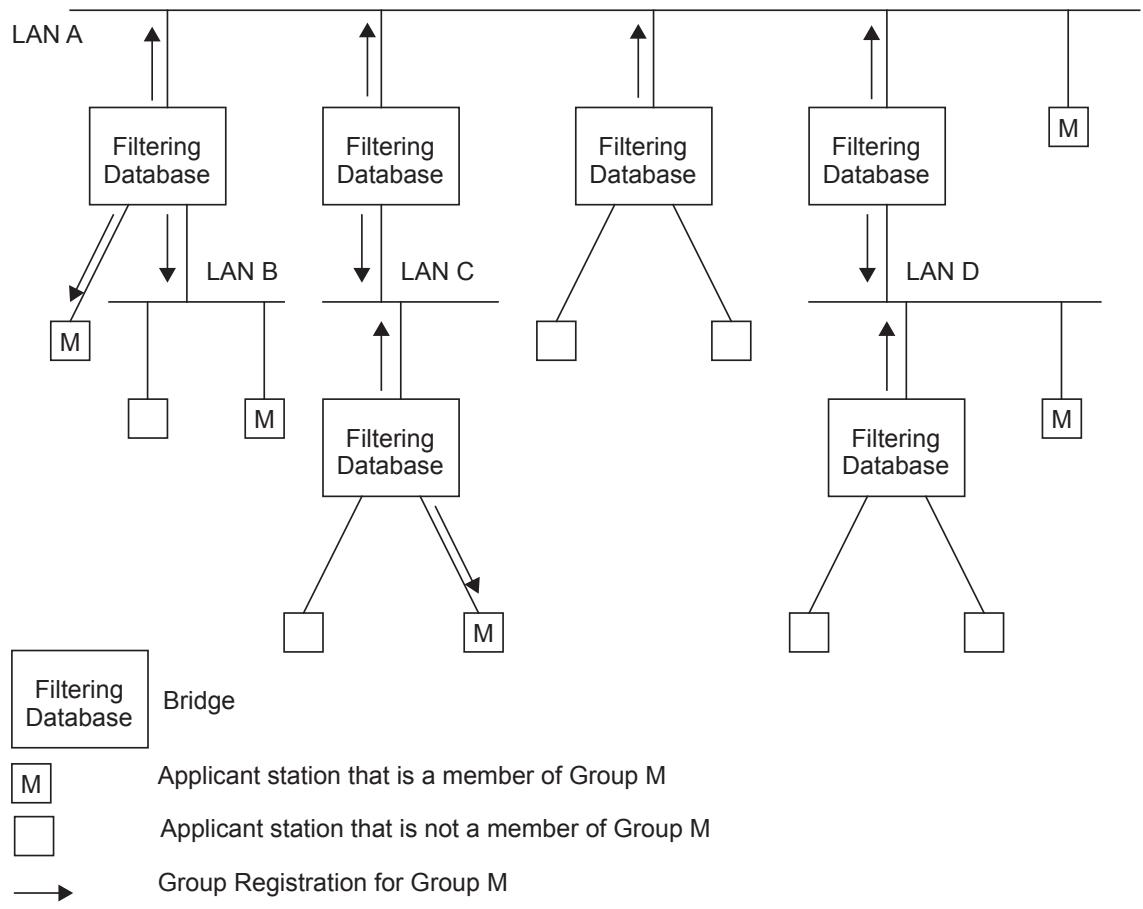
Figure 10-7—Example Directed Graph
By receiving frames from all Ports and forwarding only through Ports for which MMRP has created MAC Address Registration Entries, Bridges facilitate Group distribution mechanisms based on the concept of an Open Host Group. Any MMRP Participants (10.2) that wish to receive frames transmitted to a particular Group or Groups request membership of the Group(s) concerned. Any MAC Service user that wishes to send frames to a particular Group can do so from any point of attachment to the Bridged Network. These frames can be received on all LANs to which registered MMRP Participants are attached, but the filtering applied by Bridges ensures that frames are not transmitted on LANs that are not part of the active topology between the sources of the frames and the registered Group members. MMRP and the MAC Address Registration Entries thus restrict the frames to pruned subsets of the overall loop-free active topology.
NOTE—The term “Open Host Group” comes from the terminology introduced in the definition of the Internet Group Membership Protocol (IGMP) defined by the IETF.
MAC Service users that are sources of MAC frames destined for the Group do not have to register as members of the Group themselves unless they also wish to receive frames transmitted to the Group address by other sources.
10.10.2 Propagation of Group service requirement information
MMRP propagates Group service requirement information in the same manner as for Group registration information. If any Port in a given Bridge has a registered Group service requirement of All Groups or All Unregistered Groups (expressed in terms of the control information in Static Filtering Entries and/or MAC Address Registration Entries with a MAC address specification of All Groups or All Unregistered Groups), this fact is propagated on all other Ports of the Bridge, resulting in the registration of that information on Ports of adjacent Bridges. As a consequence of that registration, the default Group filtering behavior of those Ports can change in order to maintain compatibility with the service requirements expressed by the registered information, as defined in 8.8.6. This ensures that connectivity can be maintained in LANs where the service requirements of different regions of the Bridged Network differ.
NOTE—In a Bridged Network where the default Group filtering behavior is not the same for all “edge” Ports, service requirement propagation will tend to result in all “backbone” Ports switching to the highest precedence Group filtering behavior in use in the network. The precedence rules are defined in 8.8.6.
10.10.3 Source pruning
As described in 10.10.1, the operation of MMRP defines a subtree of the spanning tree as a result of the creation of MAC Address Registration Entries in the FDBs of the Bridges. End stations are also able to make use of the Group Membership information registered via MMRP to allow them to keep track of the set of Groups for which active members currently exist and the service requirements of upstream devices. This allows end stations that are sources of frames destined for a Group to suppress the transmission of such frames, if their registered Group membership and Group service requirement information indicates that there are no valid recipients of those frames reachable via the LANs to which they are attached.
NOTE—In effect, for the purposes of frame transmission, the end station can be viewed as if it operates as a single Port Bridge, with its own default Group filtering behavior and FDB entries updated via MMRP that tell it whether multicast frames that it has generated should be forwarded onto the attached LAN. In order to achieve this, it is necessary for the end station to implement both the Registrar and the Applicant functionality of MRP, as described in 10.6, 10.7.7, and 10.7.8. The Applicant-Only and Simple-Applicant Participants described in 10.6 do not contain the Registrar functionality that would be required for source pruning.
This end system behavior is known as source pruning. Source pruning allows MAC Service users that are sources of MAC frames destined for a number of Groups, such as server stations or routers, to avoid unnecessary flooding of traffic on their local LANs in circumstances where there are no current Group members in the network that wish to receive such traffic.
10.10.4 Use of Group service requirement registration by end stations
The ability to propagate Group service requirement information is described in this standard primarily as a means of propagating the requirements of the Bridges themselves. However, this mechanism can also be used by end stations that have requirements involving some aspect of promiscuous reception, such as Routers or network monitors. A MMRP-aware end station wishing to receive all multicast traffic can declare membership of All Groups on the LAN to which it is attached; similarly, an end station that wishes to receive unregistered multicast traffic can do so by declaring membership of All Unregistered Groups.
10.11 Default Group filtering behavior and MMRP propagation
The propagation of MMRP registrations within a VLAN Context has implications with respect to the choice of default Group filtering behavior within a Bridged Network. As MMRP frames are transmitted only on outbound Ports that are in the Member set (8.8.10) for the VID concerned, propagation of Group registrations by a given Bridge occurs only toward regions of the Bridged Network where that VID has been (statically or dynamically) registered. This is illustrated in Figure 10-8; dotted lines in the diagram show those regions of the Bridged Network where propagation of registrations for Group M for VID V does not occur. Consequently, the FDBs of the lower two Bridges will not contain any Dynamic MAC Address Registration Entry for Group M for VID V.
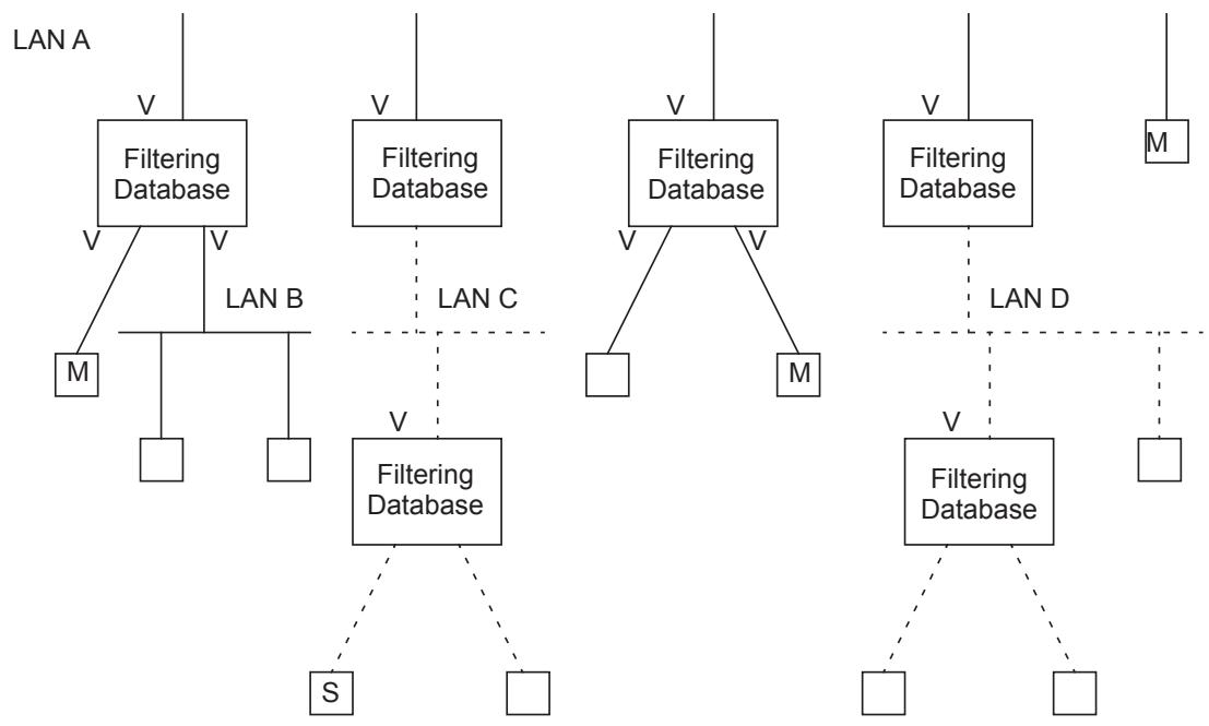
Filtering Database Bridge
M Applicant station that is a member of Group M in VLAN Context V
Applicant station that is not a member of Group M
S End station transmitting frames to Group M with VID V
Regions of the LAN where registrations for Group M in VLAN Context V are not propagated
Figure 10-8—Example of MMRP propagation in a VLAN Context
The action of these two Bridges on receipt of frames, on either of their lower Ports, destined for Group M and VID V, will depend upon the Default Group Filtering Behavior adopted by their upper Ports, which are the Ports that are in the Member set for VID V. If the Default Group Filtering Behavior is either Forward All Groups or Forward Unregistered Groups, then these Bridges will forward the frames. If the Default Group Filtering Behavior is Filter Unregistered Groups, then these Bridges will filter the frames. In the scenario shown, the choice of Default Group Filtering Behavior is therefore crucial with respect to whether end station S, or any other station that is “outside” the VLAN, is able to send frames to members of the Group. The choice between Filter Unregistered Groups and the other default behaviors therefore has the effect of defining VLANs that are closed to external unregistered traffic (Filter Unregistered Groups) or open to external unregistered traffic (either of the other default behaviors).
10.12 Definition of the MMRP application
10.12.1 Definition of MRP elements
10.12.1.1 Use of MAP Contexts by MMRP
MMRP operates within a MAP Context, or set of MAP Contexts, that is determined by the type of Bridge component supporting the MMRP application. In a MAC Bridge component MMRP operates in the Base Spanning Tree Context. In a C-VLAN component or S-VLAN component MMRP operates in the set of C-VLAN Contexts or S-VLAN Contexts, respectively, that corresponds to the VIDs that are supported by the Virtual Bridged Network.
The MAP Context Identifier used to identify a VLAN Context shall be equal to the VID used to identify the corresponding VLAN.
The set of Ports of a Bridge defined to be part of the active topology for a given VLAN Context shall be equal to the set of Ports of a Bridge for which the following are true:
a) The Port is a member of the Member set (8.8.10) for that VID; and
b) The Port is one of the Ports of the Bridge that are part of the active topology for the spanning tree that supports that VID.
NOTE—The above definition applies equally to SST and MST environments. It ensures that MMRP operates in either environment, without the MMRP implementations needing to be aware of whether the VLAN Contexts that apply are all supported by the same spanning tree, as in the SST environment, or are potentially distributed across two or more spanning trees, as in the MST environment.
VLAN Contexts can be hierarchical. For example, in a PBN that forwards C-VLAN-tagged frames between CBNs, there can be multiple C-VLAN Contexts within each S-VLAN context. Likewise, there can be multiple C-VLAN Contexts and/or S-VLAN Contexts within the Base Spanning Tree Context. While it is theoretically possible for an MMRP application to support hierarchical MAP Contexts by maintaining an MMRP Participant for each possible (or at least anticipated) combination of C-VLAN, S-VLAN and Base Spanning Tree MAP Contexts, an MMRP application is not required to support hierarchical MAP Contexts. The identification of MMRPDUs belonging to a hierarchical MAP Context, and the treatment of such MMRPDUs, is discussed in 10.12.1.2.
10.12.1.2 Context identification in MMRP
In a MAC Bridge component, received MMRPDUs that are untagged are identified with the Base Spanning Tree Context and are directed to the MRP Participant for the Base Spanning Tree. Received MMRPDUs that are VLAN-tagged identify hierarchical MAP Contexts. If the MMRP application does not support hierarchical MAP Contexts (i.e., maintain an MRP Participant for each possible S-VLAN and/or C-VLAN Context within the Base Spanning Tree Context), then the received MMRPDUs are not directed to any MRP Participant and are transmitted, including the original VLAN tag(s), on each port in the Base Spanning Tree Context except the reception port.
Implementations of MMRP in VLAN Bridges apply the same ingress rules (8.6.2) to received MMRPDUs that are defined for the reception Port. Therefore,
a) MMRP frames with no VLAN classification (i.e., untagged or priority-tagged MMRPDUs) are discarded if the Acceptable Frame Types parameter (6.9) for the Port is set to Admit Only VLANtagged frames. Otherwise, they are classified either according to the PVID for the Port, or as determined by protocol-based VLAN classification (6.12) if that capability is implemented.
b) VLAN-tagged MMRP frames are classified according to the VID carried in the tag header, optionally translated using the VID translation table (6.9).
c) If Ingress Filtering (8.6.2) is enabled, and if the Port is not in the Member set (8.8.10) for the MMRP frame’s VLAN classification, then the frame is discarded.
The VLAN classification thus associated with a received MMRP frame establishes the C-VLAN Context or S-VLAN Context for the received PDU, depending on whether the reception port is on a C-VLAN component or S-VLAN component, and identifies the MRP Participant instance to which the PDU is directed. MMRPDUs received at an S-VLAN component and containing a C-TAG, either alone or within an S-TAG, identify hierarchical MAP Contexts. If the MMRP application does not support hierarchical MAP Contexts (i.e., maintain an MRP Participant for each possible C-VLAN Context within each S-VLAN Context), then the received MMRPDUs are not directed to any MRP Participant and are transmitted, including the original C-TAG, on each port in the S-VLAN Context except the reception port.
MMRPDUs transmitted by MMRP Participants are VLAN classified according to the VLAN Context associated with that Participant. MMRP Participants in VLAN Bridges apply the same egress rules that are defined for the transmission Port (8.6.4). Therefore
d) MMRPDUs are transmitted through a given Port only if the Member Set for the VID concerned indicates that the VID is registered on that Port.
e) MMRPDUs are transmitted through a given Port as VLAN-tagged frames or as untagged frames in accordance with the state of the Untagged Set (8.8.10) for that Port and for the VID concerned.
Where VLAN-tagged frames are transmitted, the VID field of the tag header carries the VLAN Context Identifier value, optionally translated using the VID translation table (6.9).
10.12.1.3 MMRP application address
The group MAC address used as the destination address for MRPDUs destined for MMRP Participants shall be the group MAC address identified in Table 10-1 as “Customer and Provider Bridge MMRP address.”
10.12.1.4 MMRP application EtherType
The EtherType used for MRPDUs destined for MMRP Participants shall be the MMRP EtherType identified in Table 10-2.
10.12.1.5 MMRP ProtocolVersion
The ProtocolVersion for the version of MMRP defined in this standard takes the hexadecimal value 0x00.
10.12.1.6 MMRP AttributeType definitions
MMRP defines two AttributeTypes (10.8.2.2) that are carried in MRP exchanges, as follows:
a) The Service Requirement Vector Attribute Type.
b) The MAC Vector Attribute Type.
Attributes identified by the Service Requirement Vector Attribute Type are instances of VectorAttributes (10.8.1), used to identify values of Group service requirements. The value of AttributeType used to identify the Service Requirement Vector Attribute Type in MRPDUs (10.8.2.2) shall be 1.
Attributes identified by the MAC Vector Attribute Type are instances of VectorAttributes (10.8.1), used to identify a sequence of values of MAC addresses. The value of AttributeType used to identify the MAC Vector Attribute Type in MRPDUs (10.8.2.2) shall be 2.
10.12.1.7 MMRP FirstValue definitions
The FirstValue field (10.8.2.7) in instances of the MAC Vector Attribute Type shall be encoded in MRPDUs as six octets, each taken to represent an unsigned binary number. The octets are derived from the Hexadecimal Representation of an EUI-48 MAC Address (defined in IEEE Std 802) as follows:
a) Each two-digit hexadecimal numeral in the Hexadecimal Representation is taken to represent an unsigned hexadecimal value, in the normal way, i.e., the rightmost digit of each numeral represents the least significant digit of the value, the leftmost digit is the most significant.
b) The first octet of the attribute value encoding is derived from the left-most hexadecimal value in the Hexadecimal Representation of the MAC address. The LSB of the octet (bit 1) is assigned the LSB of the hexadecimal value, the second significant bit is assigned the value of the second significant bit of the hexadecimal value, and so on.
c) The second through sixth octets of the encoding are similarly assigned the value of the second through sixth hexadecimal values in the Hexadecimal Representation of the MAC address.
FirstValue+1 is defined as adding 1 to FirstValue. There are no restrictions on the range of values that can be represented in this data type.
The FirstValue field in instances of the Service Requirement Attribute Type shall be encoded in MRPDUs (10.8.2.7) as a single octet, taken to represent an unsigned binary number. Only two values of this type are defined:
d) All Groups shall be encoded as the value 0.
e) All Unregistered Groups shall be encoded as the value 1.
The remaining possible values (2 through 255) are reserved.
10.12.1.8 MMRP AttributeLength definitions
The AttributeLength field (10.8.2.3) in instances of the MAC Vector Attribute Type shall be encoded in MRPDUs (10.8) as an unsigned binary number, equal to the value 0x06.
The AttributeLength field (10.8.2.3) in instances of the Service Requirement Vector Attribute Type shall be encoded in MRPDUs (10.8) as an unsigned binary number, equal to the value 0x01.
10.12.1.9 MMRP AttributeListLength definitions
The AttributeListLength field (10.8.2.4) is not present in the MMRPDUs.
10.12.1.10 MMRP Vector definitions
The ThreePackedEvent vectors are encoded as defined in 10.8.2.10.1.
The FourPackedEvent vectors (10.8.2.10.2) are not present in the MMRPDUs.
10.12.2 Provision and support of Extended Filtering Services
10.12.2.1 Initiating MMRP registration and deregistration
The MMRP application element of an MRP Participant provides the dynamic registration and deregistration services defined in 6.16.7.1, as follows:
On receipt of a REGISTER_MAC_ADDRESS service primitive, the MMRP Participant issues a MAD_Join.request. The attribute_type parameter of the request carries the value of the MAC Vector Attribute Type (10.12.1.6) and the attribute_value parameter carries the value of the MAC_ADDRESS parameter of the service primitive.
On receipt of a DEREGISTER_MAC_ADDRESS service primitive, the MMRP Participant issues a MAD_Leave.request. The attribute_type parameter of the request carries the value of the MAC Vector Attribute Type (10.12.1.6) and the attribute_value parameter carries the value of the MAC_ADDRESS parameter of the service primitive.
On receipt of a REGISTER_SERVICE_REQUIREMENT service primitive, the MMRP Participant issues a MAD_Join.request. The attribute_type parameter of the request carries the value of the Service Requirement Vector Attribute Type (10.12.1.6) and the attribute_value parameter carries the value of the REQUIREMENT_SPECIFICATION parameter of the service primitive.
On receipt of a DEREGISTER_SERVICE_REQUIREMENT service primitive, the MMRP Participant issues a MAD_Leave.request. The attribute_type parameter of the request carries the value of the Service Requirement Vector Attribute Type (10.12.1.6) and the attribute_value parameter carries the value of the REQUIREMENT_SPECIFICATION parameter of the service primitive.
NOTE—If the EISS is supported, the Extended Filtering service primitives issued by the MAC Service user should include a VID parameter in addition to the MAC_ADDRESS or REQUIREMENT_SPECIFICATION parameters, in order to identify the MMRP Participant associated with the primitive.
10.12.2.2 Registration and deregistration events
The MMRP application element of an MRP Participant responds to registration and deregistration events signaled by MAD as follows:
On receipt of a MAD_Join.indication, the MMRP application element specifies the Port associated with the MMRP Participant as Forwarding in the Port Map field of the MAC Address Registration Entry (8.8.4) for the MAC address specification carried in the attribute_value parameter and the VID associated with the MAP Context. If such a MAC Address Registration Entry does not exist in the FDB, a new MAC Address Registration Entry is created.
Creation of new MAC Address Registration Entries may be restricted by the Restricted_MAC_Address_Registration control (10.12.2.3). If this control is TRUE, creation of a new dynamic entry is permitted only if there is a Static Filtering Entry for the MAC address with a Registrar Administrative Control value of Normal Registration.
NOTE—Group Membership and Group service requirement information can be recorded in the FDB by means of MAC Address Registration Entries (see 8.8.4). In the case of Group Membership Information, the MAC address specification in the MAC Address Registration Entry is a group MAC address. In the case of Group service requirement information, the MAC address specification is either “All Group Addresses” or “All Unregistered Group Addresses.”
On receipt of a MAD_Leave.indication, the MMRP application element specifies the Port associated with the MMRP Participant as Filtering in the Port Map field of the MAC Address Registration Entry (8.8.4) for the MAC address specification carried in the attribute_value parameter and the VID associated with the MAP Context. If such an FDB entry does not exist in the FDB, then the indication is ignored. If setting that Port to Filtering results in there being no Ports in the Port Map specified as Forwarding (i.e., all MMRP members are deregistered), then that MAC Address Registration Entry is removed from the FDB.
10.12.2.3 Administrative controls
The provision of static control over the registration state of the state machines associated with the MMRP application is achieved by means of the Registrar Administrative Control parameters associated with the operation of MRP (10.7.2). These parameters are represented in the FDB by the information held in Static Filtering Entries (8.8.1). If no Static Filtering Entry exists for a given MAC address specification, the value of the Registrar Administrative Control parameter for the corresponding attribute value is Normal Registration for all Ports of the Bridge.
The initial state of the Permanent Database (i.e., the state of the Permanent Database in a Bridge that has not been otherwise configured by management action) includes a Static Filtering Entry with a MAC address specification of All Groups, in which the Port Map indicates Registration Fixed (New ignored). This Static Filtering Entry will have the effect of determining the default Group filtering behavior of all Ports of the Bridge to be Forward All Groups. This Permanent Database entry may be deleted or updated by management action..
NOTE—This specification of an initial Static Filtering Entry means that operation using Forward Unregistered Groups or Filter Unregistered Groups requires a conscious action on the part of the network manager or administrator.
Where management capability is implemented, the Registrar Administrative Control parameters can be applied and modified by means of the management functionality defined in 12.7.
The provision of static control over the ability of Applicant state machines to participate in protocol exchanges is achieved by means of the Applicant Administrative Control parameters associated with the operation of MRP (10.7.3). Where management capability is implemented, the Applicant Administrative Control parameters can be applied and modified by means of the management functionality defined in Clause 12.
Further administrative control over dynamic MAC address registration may be achieved, if supported, by means of a per-Port Restricted_MAC_Address_Registration control parameter. If the value of this control is TRUE for a given Port, the creation or modification of Dynamic MAC Address Registration Entries as a result of MMRP exchanges on that Port shall be restricted only to those MAC addresses for which Static Filtering Entries exist in which the Registrar Administrative Control value is Normal Registration. If the value of the Restricted_MAC_Address_Registration control is FALSE, dynamic MAC address registration is not so restricted. Where management capability is implemented, the value of the Restricted_MAC_Address_Registration control can be manipulated by means of the management functionality defined in Clause 12. If management of this parameter is not supported, the value of this parameter shall be FALSE for all Ports.
10.12.3 Use of “new” declaration capability
MMRP does not make use of the “new” declaration capability.
10.12.4 Attribute value support requirements
Implementations of MMRP shall maintain state information for all attribute values that support the Group service requirement registration (10.12.1.7).
Implementations of MMRP shall be capable of supporting any attribute value in the range of possible values that can be registered using Group membership and individual MAC address registration (10.12.1.7); however, the maximum number of attribute values for which the implementation is able to maintain current state information is an implementation decision. The number of values that the implementation can support shall be stated in the PICS.
10.12.5 Registrar Administrative Controls
MMRP supports the Registration Fixed (New ignored) value, but not the Registration Fixed (New propagated) value, of the Registrar Administrative Controls (10.7.2)
11 VLAN topology management
The egress rules (8.6.4) defined for the Forwarding Process in VLAN Bridges rely on the existence of configuration information for each VID that defines the set of Ports of the Bridge through which one or more members are reachable. This set of Ports is known as the Member Set (8.8.10), and its membership is determined by the presence or absence of configuration information in the FDB, in the form of Static and Dynamic VLAN Registration Entries (8.8.2, 8.8.5).
Reliable operation of the VLAN infrastructure requires VLAN membership information held in the FDB to be maintained in a consistent manner across all VLAN Bridges in the Virtual Bridged Network, in order to ensure that frames destined for end station(s) on a given VLAN can be correctly delivered, regardless of where in the Bridged Network the frame is generated. Maintenance of this information by end stations that are sources of VLAN-tagged frames can allow such stations to suppress transmission of such frames if no members exist for the VLAN concerned.
This standard defines the following mechanisms that allow VLAN membership information to be configured:
a) Dynamic configuration and distribution of VLAN membership information by means of the MVRP, as described in 11.2.
b) Static configuration of VLAN membership information via Management mechanisms, as described in Clause 12, which allow configuration of Static VLAN Registration Entries.
These mechanisms provide for the configuration of VLAN membership information as a result of the following:
c) Dynamic registration actions taken by end stations or Bridges in the Bridged Network.
d) Administrative actions.
11.1 Static and dynamic VLAN configuration
The combined functionality provided by the ability to configure Static VLAN Registration Entries in the FDB, coupled with the use of the Restricted_VLAN_Registration control (11.2.3.2.3) and the ability of MVRP to dynamically create and update Dynamic VLAN Registration Entries, offers the following possibilities with respect to how VIDs are configured on a given Port:
a) Static configuration only. The management facilities described in Clause 12 are used to establish precisely which VIDs have this Port in their Member set, and the MVRP management controls are used to disable the operation of MVRP on that Port. Hence, any use of MVRP by devices reachable via that Port is ignored, and the Member set for all VIDs can therefore only be determined by means of static entries in the FDB.
b) Static configuration with topology changes. The management facilities described in Clause 12 are used to establish precisely which VLANs have this Port in their Member set, and the MVRP or MIRP management controls are used to permit the signaling, via MVRP or MIRP, of network topology changes that require flushing learned address information from the FDB. MVRPDUs and MIRPDUs received from devices reachable via that Port are ignored for the purposes of creating or deleting Dynamic VLAN Registration Entries in the FDB on that Port, and the Member set for all VLANs can therefore only be determined by means of static entries in the FDB.
c) Dynamic configuration only. The operation of MVRP is relied upon to establish Dynamic VLAN Registration Entries that will dynamically reflect which VIDs are registered on the Port, their contents changing as the configuration of the network changes. The MVRP management controls are set to enable the operation of MVRP on that Port.
d) Combined static and dynamic configuration. The static configuration mechanisms are used in order to configure some VLAN membership information; for other VIDs, MVRP is relied upon to establish the configuration. The MVRP management controls are set to enable the operation of MVRP on that Port.
All of the previous approaches are supported by the mechanisms defined in this standard, and each approach is applicable in different circumstances. For example:
e) Use of static configuration may be appropriate on Ports where the configuration of the attached devices is fixed, or where the network administrator wishes to establish an administrative boundary outside of which any MVRP registration information is to be ignored. For example, it might be desirable for all Ports serving end user devices to be statically configured in order to ensure that particular end users have access only to VLANs identified by particular VIDs.
f) Use of static configuration with topology changes can be appropriate where the configuration of VLANs and ports is static in some part of the network, but dynamic in another part, so that changes in the topology of the dynamic part can necessitate the flushing of learned MAC address information in Bridges in the static part. For example, in a PBBN, a topology change in a customer network with dual attachments to the provider can require a provider’s I-component to signal a MAC address flush across the backbone, even though the VLANs on the VIPs involved are statically configured.
g) Use of dynamic configuration may be appropriate on Ports where the VLAN configuration is inherently dynamic; where users of particular VIDs can connect to the network via different Ports on an ad hoc basis, or where it is desirable to allow dynamic reconfiguration in the face of spanning tree topology changes. In particular, if the “core” of the Virtual Bridged Network contains redundant paths that are pruned by the operation of the spanning tree protocol, then it is desirable for Bridge Ports that form the core network to be dynamically configured.
h) Use of both static and dynamic configuration can be appropriate on Ports where it is desirable to place restrictions on the configuration of some VIDs, while maintaining the flexibility of dynamic registration for others. For example, on Ports serving mobile end user devices, this would maintain the benefits of dynamic VLAN registration from the point of view of traffic reduction, while still allowing administrative control over some VIDs via that Port.
11.2 Multiple VLAN Registration Protocol (MVRP)
MVRP defines an MRP application that provides the VLAN registration service defined in 11.2.2. MVRP makes use of MRP Attribute Declaration (MAD) and MRP Attribute Propagation (MAP), which provide the common state machine descriptions and the common attribute propagation mechanisms defined for use in MRP-based applications. The MRP architecture, MAD, and MAP are defined in Clause 10.
MVRP provides a mechanism for dynamic maintenance of the contents of Dynamic VLAN Registration Entries for each VID, and for propagating the information they contain to other Bridges. This information allows MVRP-aware devices to dynamically establish and update their knowledge of the set of VIDs associated with VLANs that currently have active members, and through which Ports those members can be reached.
11.2.1 MVRP overview
The operation of MVRP is closely similar to the operation of MMRP (10.9), which is used for registering Group membership and individual MAC address information. The primary differences are as follows:
a) The attribute values carried by the protocol are 12-bit VID values, rather than Group service requirement information and EUI-48 MAC Addresses.
b) The act of registering/deregistering a VID affects the contents of Dynamic Registration Entries (8.8.5), rather than the contents of MAC Address Registration Entries (8.8.4).
c) In an SST environment, there is a single MVRP Participant per port, as opposed to one MMRP Participant per VID per port, and the MVRP Participants all operate in a single MAP Context.
In an MST environment, there is again a single MVRP Participant per port, but each MVRP Participant operates in multiple MAP Contexts.
MVRP allows both end stations and Bridges in a Bridged Network to issue and revoke declarations relating to membership of VLANs. The effect of issuing such a declaration is that each MVRP Participant that receives the declaration will create or update a Dynamic VLAN Registration Entry in the FDB to indicate that VID is registered on the reception Port. Subsequently, if all Participants on a LAN that had an interest in a given VID revoke their declarations, the Port attached to that LAN is set to Unregistered in the Dynamic VLAN Registration Entry for that VID by each MVRP Participant attached to that LAN.
Figure 11-1 illustrates the architecture of MVRP in the case of a two-Port Bridge and an end station.
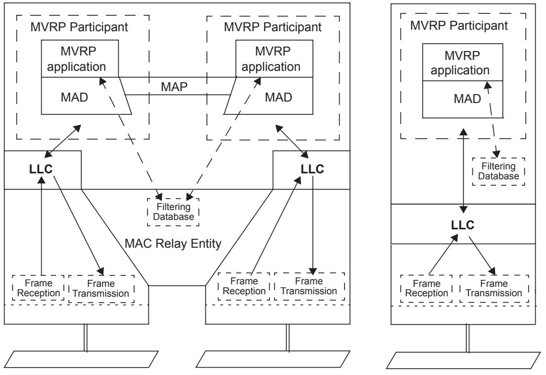
Figure 11-1—Operation of MVRP
As shown in the diagram, the MVRP Participant consists of the following components:
e) The MVRP application, described in 11.2.3
f) MRP Attribute Propagation (MAP), described in 10.3
g) MRP Attribute Declaration (MAD), described in 10.2
11.2.1.1 Behavior of end stations
VLAN-aware end stations participate in MVRP activity, as appropriate for the set of VIDs of VLANs of which they are currently members. MVRP provides a way for such an end station to ensure that the VIDs of VLAN(s) of which it is a member are registered for each Port on any LAN to which the end station is attached. MVRP also provides for that VID information to be propagated across the spanning tree to other VLAN-aware devices, as described in 11.2.1.2.
Incoming VLAN membership information (from all other devices on the same LAN) allows such end stations to “source prune” (i.e., discard at source; see 10.10.3) any traffic destined for VLANs that currently have no other members in the Bridged Network, thus avoiding the generation of unnecessary traffic on their local LANs. This is illustrated in Figure 11-1 by an FDB shown as being present in the end station.
NOTE—Non-VLAN-aware end stations have no need to register VLAN membership via MVRP; indeed, this would be impossible for them to achieve if truly VLAN-unaware, as they would have no knowledge of the set of VLANs in which they participate. Their VLAN registration requirements are taken care of by means of the configuration of PVIDs (and possibly other VLAN classification mechanisms) and the propagation of registered VIDs by the Bridges.
11.2.1.2 Behavior of Bridges
VLAN Bridges register and propagate VLAN memberships on all Bridge Ports that are part of the active topology of the underlying spanning tree(s). Incoming VID registration and deregistration information is used to update the Dynamic VLAN Registration Entries associated with each VID. Any changes in the state of registration of a given VID on a given Port are propagated on Ports that are part of the active topology of the underlying spanning tree, in order to ensure that other MVRP-aware devices in the Bridged Network update their FDBs appropriately. In Bridges that support multiple spanning tree instances, the MST Configuration Table (12.12, 13.8) is used to determine which spanning tree instance is to be used to propagate registration information for each supported VID.
The FDBs in all MVRP-aware devices are thus automatically configured such that the Port Map in the Dynamic VLAN Registration Entry for a given VID indicates that a given Port is registered if one or more members of the corresponding VLAN are reachable through the Port.
NOTE—The information that determines whether frames destined for each VID are transmitted VLAN-tagged or untagged is carried in Static VLAN Registration Entries (8.8.2); if no such entry exists for a VID, then it is assumed that frames for that VID are transmitted VLAN-tagged on all Ports. Therefore, if the configuration information held in the FDB for a given VID consists only of information configured by the operation of MVRP (i.e., only a Dynamic VLAN Registration Entry), then all traffic for that VID will be VLAN-tagged on transmission.
11.2.1.3 Use of the PVID and VID Set
The initial state of the Permanent Database contains a Static VLAN Registration Entry for the Default PVID, in which the Port Map indicates Registration Fixed (New ignored) on all Ports. This ensures that in the default state, where the value of every PVID of each Port is the Default PVID and where the VID Set of each Port is empty, membership of the Default PVID is propagated across the Bridged Network to all other MVRP-aware devices. Subsequent management action may change both the Permanent Database and the FDB in order to modify or remove this initial setting, and may change the PVID and/or VID Set value(s) on any Port of the Bridge.
NOTE—In the absence of any modification of these initial settings, this ensures that connectivity is established across the Bridged Network for the VLAN corresponding to the Default PVID.
11.2.2 VLAN registration service definition
The VLAN registration service allows MAC Service users to indicate to the MAC Service provider the set of VLANs in which they wish to participate; i.e., that the MAC Service user wishes to receive traffic destined for members of that set of VLANs. The service primitives allow the service user to
a) Register membership of a VLAN
b) Deregister membership of a VLAN
Provision of these services is achieved by means of MVRP and its associated procedures, as described in 11.2.3.
ES_REGISTER_VLAN_MEMBER (VID)
Indicates to the MAC Service provider that the MAC Service user wishes to receive frames destined for the VLAN identified by the VID parameter.
ES_DEREGISTER_VLAN_MEMBER (VID)
Indicates to the MAC Service provider that the MAC Service user no longer wishes to receive frames destined for the VLAN identified by the VID parameter.
The use of these services can result in the propagation of VID information across the spanning tree, affecting the contents of Dynamic VLAN Registration Entries (8.8.5) in Bridges and end stations in the Bridged Network, and thereby affecting the frame forwarding behavior of those Bridges and end stations.
11.2.3 Definition of the MVRP application
11.2.3.1 Definition of MRP elements
11.2.3.1.1 MAP Context for MVRP in SST environments
In an SST environment, MVRP operates in the Base Spanning Tree Context (10.3.1); i.e., MVRP operates only on the CIST. Consequently, all MVRPDUs sent and received by MVRP Participants in SST Bridges are transmitted as untagged frames.
11.2.3.1.2 MAP Contexts for MVRP in MST environments
In an MST environment, MVRP operates in multiple spanning tree contexts, one for each of the spanning trees. Each spanning tree context consists of the ports that are in the forwarding state for the corresponding spanning tree. The MVRP Participants associated with a given spanning tree operate in the MAP context identified by that spanning tree instance. MST Bridges can identify the MAP Contexts using the mappings of VID values to MSTID values (see 8.9.1). All MVRPDUs sent and received by MVRP Participants in MST Bridges are transmitted as untagged frames.
11.2.3.1.3 MVRP application address
The group MAC address used as the destination address for MRPDUs destined for MVRP Participants shall be either
a) The group MAC address identified in Table 10-1 as “Customer Bridge MVRP address” if the MVRP Participant is implemented in a C-VLAN component; or
b) The group MAC address identified in Table 8-1 as “Provider Bridge MVRP Address” if the MVRP Participant is implemented in an S-VLAN component.
11.2.3.1.4 MVRP application EtherType
The EtherType used for MRPDUs destined for MVRP Participants shall be the MVRP EtherType identified in Table 10-2.
11.2.3.1.5 MVRP ProtocolVersion
The ProtocolVersion for the version of MVRP defined in this standard takes the hexadecimal value 0x00.
11.2.3.1.6 MVRP AttributeType definitions
MVRP defines a single Attribute Type (10.8.2.2) that is carried in MRP exchanges, as follows:
Attributes identified by the VID Vector Attribute Type are instances of VectorAttributes (10.8.1), used to identify a sequence of values of VIDs. The value of AttributeType used to identify the VID Vector Attribute Type in MRPDUs (10.8.2.2) shall be 1.
11.2.3.1.7 MVRP FirstValue definitions
The FirstValue field in instances of the VID Vector Attribute Type shall be encoded in MRPDUs (10.4) as two octets, taken to represent an unsigned binary number, and equal to the value of the VID that is to be encoded.
The range of permitted values that can be encoded in the FirstValue fields in MVRP is restricted to the range 0 through 4094.The value 0 represents the VID of the untagged frame on which the MRPDU is transmitted or received, and 1 through 4094 identify specific VIDs. If enabled by management [item (e) in 12.9.2.2.2], and if there is only one VID whose untagged set includes the Port of an MVRP Participant, the Participant shall transmit the value 0 in place of that VID. All MVRP Participants shall translate the value 0 in a received message to the PVID of the receiving Port.
NOTE—Previous revisions of this Standard did not provide for transmission or reception of 0 as an MVRP Attribute value. No automatic means for determining whether the other MVRP Participants on a LAN are capable of receiving the value 0 are provided. Therefore, extreme care is in order when configuring an MVRP Participant to transmit Attribute value 0, as compliant implementations of previous revisions of this standard could drop such MRPDUs as badly formed.
11.2.3.1.8 MVRP AttributeLength definitions
The AttributeLength field (10.12.1.8) in instances of the VID Vector Attribute Type shall be encoded in MRPDUs (10.8) as an unsigned binary number, equal to the value 0x02.
11.2.3.1.9 MVRP AttributeListLength definitions
The AttributeListLength field (10.8.2.4) is not present in the MVRPDUs.
11.2.3.1.10 MVRP Vector definitions
The ThreePackedEvent vectors are encoded as defined in 10.8.2.10.1.
The FourPackedEvent vectors (10.8.2.10.2) are not present in the MVRPDUs.
11.2.3.2 Provision and support of the VLAN registration service
11.2.3.2.1 Initiating VLAN membership declaration
The MVRP application element of a MVRP Participant provides the dynamic registration and deregistration services defined in 11.2.2, as follows:
On receipt of an ES_REGISTER_VLAN_MEMBER service primitive, the MVRP Participant issues a MAD_Join.request service primitive (10.2, 10.3). The attribute_type parameter of the request carries the value of the VID Vector Attribute Type (11.2.3.1.6) and the attribute_value parameter carries the value of the VID parameter carried in the ES_REGISTER_VLAN_MEMBER primitive.
On receipt of an ES_DEREGISTER_VLAN_MEMBER service primitive, the MVRP Participant issues a MAD_Leave.request service primitive (10.2, 10.3). The attribute_type parameter of the request carries the value of the VID Vector Attribute Type (11.2.3.1.6) and the attribute_value parameter carries the value of the VID parameter carried in the ES_DEREGISTER_VLAN_MEMBER primitive.
11.2.3.2.2 VLAN membership registration
The MVRP application element of a MVRP Participant responds to registration and deregistration events signaled by MAD as follows:
On receipt of a MAD_Join.indication whose attribute_type is equal to the value of the VID Vector Attribute Type (11.2.3.1.6), the MVRP application element indicates the reception Port as Registered in the Port Map of the Dynamic VLAN Registration Entry for the VID indicated by the attribute_value parameter. If no such entry exists, there is sufficient room in the FDB, and the VID is within the range of values supported by the implementation (see 9.6), then an entry is created. If not, then the indication is not propagated and the registration fails.
The creation of new Dynamic VLAN Registration Entries can be restricted by use of the Restricted_VLAN_Registration control (11.2.3.2.3). If the value of this control is TRUE, then creation of a new dynamic entry is permitted only if there is a Static VLAN Registration Entry for the VID concerned, in which the Registrar Administrative Control value is Normal Registration.
On receipt of a MAD_Leave.indication whose attribute_type is equal to the value of the VID Vector Attribute Type (11.2.3.1.6), the MVRP application element indicates the reception Port as not Registered in the Port Map of the Dynamic VLAN Registration Entry for the VID indicated by the attribute_value parameter. If no such entry exists, the indication is ignored.
11.2.3.2.3 Administrative controls
The provision of static control over the declaration or registration state of the state machines associated with the MVRP application is achieved by means of the Registrar Administrative Control parameters provided by MRP (10.7.2). These parameters are represented as Static VLAN Registration Entries in the FDB (8.8.2). Where management capability is implemented, these parameters can be manipulated by means of the management functionality defined in 12.7.
The provision of static control over the ability of Applicant and Registrar state machines to participate in protocol exchanges is achieved by means of the Applicant Administrative Control parameters and Registrar Administrative Control parameters associated with the operation of MRP (10.7.2, 10.7.3). Where management capability is implemented, the Applicant and Registrar Administrative Control parameters can be applied and modified by means of the management functionality defined in 12.9. A separate managed variable [item (c) in 12.9.2.1.3] controls whether the Applicant state machine transmits 0 or the VID as the Attribute for a VLAN on a Port in that VLAN’s untagged set.
Further administrative control over dynamic VLAN registration can be achieved, if supported, by means of a per-Port Restricted_VLAN_Registration control parameter. If the value of this control is TRUE for a given Port, the creation or modification of Dynamic VLAN Registration Entries as a result of MVRP exchanges on that Port shall be restricted only to those VIDs for which Static VLAN Registration Entries exist in which the Registrar Administrative Control value is Normal Registration. If the value of the Restricted_VLAN_Registration control is FALSE, dynamic VLAN registration is not so restricted. The recommended default value of this parameter is FALSE. Where management capability is implemented, the value of the Restricted_VLAN_Registration control can be manipulated by means of the management functionality defined in 12.10. If management of this parameter is not supported, the value of this parameter shall be FALSE for all Ports.
11.2.4 VID translation table
If a VID Translation Table (6.9) is in use for a Bridge Port, the VID values received in MVRP Attributes are translated on reception of MVRPDUs prior to MVRP processing as specified in this subclause (11.2), and translated after processing for encoding MVRP Attributes in transmitted MVRPDUs. The interpretation of the MVRP Attribute value 0 is not affected by the VID Translation Table in either direction.
NOTE—In the case that the Port on which an MVRPDU is transmitted is in the untagged set of the VID matching the PVID of the Port receiving the MVRPDU, the use of the value 0 in the FirstValue field effectively performs a VID translation.
11.2.5 Use of “new” declaration capability
MVRP makes use of the “new” declaration capability in order to allow FDB entries to be removed or rapidly aged out on a per-VID basis following a topology change in the network connectivity supporting the VID concerned. The rules for propagation of “new” declarations as defined in Clause 10 ensure that all MADs that originate from, or are propagated through, a Bridge Port that has recently transitioned to Forwarding are marked as “new” declarations.
When any MVRP declaration marked as “new” is received on a given Port, either as a result of receiving an MVRPDU from the attached LAN (MAD_Join.indication), or as a result of receiving a request from MAP or the MVRP Application (MAD_Join.request), any Dynamic Filtering Entries in the FDB for that Port and for the VID corresponding to the attribute value in the MAD_Join primitive are removed.
11.2.6 New-Only Participant and Registrar Administrative Controls
A Bridge may support an MVRP New-Only Participant (10.6). This can be useful in an I-component that has statically configured S-VLAN registrations, but must still accommodate signaling the flushing of learned MAC address information. The choice of whether a given Port’s MVRP Participant operates as a Full Participant or a New-Only Participant is controlled by a managed object [12.9.2]. This managed object is separate from the one controlling whether a given Port uses Registration Fixed (New ignored) or Registration Fixed (New propagated) Static VLAN Registration Entries [item (d) in 12.7.7.3.3].
NOTE 1—Configuring an MVRP Participant as a New-Only Participant makes the assumption that all of the MVRP Participants on the LAN are configured completely via Static VLAN Registration Entries, and that no Dynamic VLAN Registration Entries are needed. If this assumption is violated, then the Bridged Network can fail to provide connectivity for the VLANs that need Dynamic VLAN Registration Entries. Therefore, extreme care is in order when configuring a New-Only MVRP Participant.
If a MAD_Join.indication is received by the MVRP MAD with the new parameter set, e.g., because a “new” MVRP declaration is received on a Port configured for New propagated [item (d) in 12.7.7.3.3] as a result of receiving an MVRPDU from the attached LAN, and that MAD_Join.indication does not correspond to a Static VLAN Registration Entry of Registration Fixed (New propagated) in the FDB, that MAD_Join.indication shall be discarded without being propagated.
NOTE 2—If only one S-VLAN is configured per VIP, then using a MIRP Participant (Clause 39) can provide bandwidth and processing savings over using an MVRP New-Only Participant on a VIP. See 39.2.1.1 and 39.2.1.6.
11.2.7 Attribute value support requirements
Implementations of MVRP shall be capable of supporting all attribute values in the range of possible values that can be registered using MVRP, and shall be capable of maintaining current state information for all attributes in the range of possible values.
12 Bridge management
This clause defines the set of managed objects, and their functionality, that allow administrative configuration of VLANs.
This clause
a) Introduces the functions of management to assist in the identification of the requirements placed on Bridges for the support of management facilities.
b) Establishes the correspondence between the Processes used to model the operation of the Bridge (8.3) and the managed objects of the Bridge.
c) Specifies the management operations supported by each managed object.
12.1 Management functions
Management functions relate to the users’ needs for facilities that support the planning, organization, supervision, control, protection, and security of communications resources, and account for their use. These facilities may be categorized as supporting the functional areas of Configuration, Fault, Performance, Security, and Accounting Management. Each functional area is summarized in 12.1.1 through 12.1.5, together with the facilities commonly required for the management of communication resources, and the particular facilities provided in that functional area by Bridge Management.
It can be necessary, particularly in PBNs, for multiple organizations to manage a single Bridge, with each organization having different abilities to manage, or even detect the existence of, Bridge Ports, Bridges, or entire networks. Access to all of the managed objects in Clause 12 for reading, writing, or detection can be restricted. Access by certain organizations can be limited to only a small number of managed objects, particularly to those specified in 12.14.
12.1.1 Configuration Management
Configuration Management provides for the identification of communications resources, initialization, reset and close-down, the supply of operational parameters, and the establishment and discovery of the relationship between resources. The facilities provided by Bridge Management in this functional area are
a) The identification of all Bridges that together make up the network and their respective locations and, as a consequence of that identification, the location of specific end stations to particular individual LANs.
b) The ability to remotely reset, i.e., reinitialize, specified Bridges.
c) The ability to control the priority with which a Bridge Port transmits frames.
d) The ability to force a specific configuration of a spanning tree.
e) The ability to control the propagation of frames with specific group MAC addresses to certain parts of the configured network.
f) The ability to identify the VIDs in use, and through which Ports of the Bridge and for which Protocols frames destined for a given VID may be received and/or forwarded.
g) The ability to create and delete the functional elements of CFM and to control their operation.
h) The ability to create and delete the functional elements of DDCFM and to control their operations.
i) The ability to create and delete the functional elements of congestion notification and to control their operation.
j) The ability to control the operation of MIRP.
k) The ability to control the operation of SPB.
l) The ability to configure the functional elements of EVB and to control their operation.
12.1.2 Fault Management
Fault Management provides for fault prevention, detection, diagnosis, and correction. The facilities provided by Bridge Management in this functional area are
a) The ability to identify and correct Bridge malfunctions, including error logging and reporting.
b) Within the context of multiple management organizations, the ability to
1) Actively monitor the connectivity of a set of managed endpoints on individual VLANs, simultaneously over multiple physical extents;
2) Actively monitor and ensure the segregation of data among different VLANs;
3) Issue trains of point-to-point query-response messages to selected network components in a VLAN;
4) Issue multicast query-relay-response messages to determine the path taken by frames addressed to specific individual MAC addresses through a VLAN;
5) Determine whether a flow of specified data frames (e.g., frames associated with a service instance or selected data frames with certain destination address) can reach a particular destination; and
6) Determine whether a flow of data frames can be sent without error from a specific location within a network to a station or stations specified by the DA field of each frame.
12.1.3 Performance Management
Performance Management provides for evaluation of the behavior of communications resources and of the effectiveness of communication activities. The facilities provided by Bridge Management in this functional area are as follows:
a) The ability to gather statistics relating to performance and traffic analysis. Specific metrics include network utilization, frame forward, and frame discard counts for individual Ports within a Bridge.
12.1.4 Security Management
Security Management provides for the protection of resources. Bridge Management does not provide any specific facilities in this functional area.
12.1.5 Accounting Management
Accounting Management provides for the identification and distribution of costs and the setting of charges. Bridge Management does not provide any specific facilities in this functional area.
12.2 VLAN Bridge objects
Managed objects model the semantics of management operations. Operations on an object supply information concerning, or facilitate control over, the process or entity associated with that object.
The managed resources of a VLAN Bridge or Bridge component are those of the processes and entities in 8.3. Specifically,
a) The Bridge Management Entity (12.4 and 8.12).
b) The individual MAC Entities associated with each Bridge Port (12.5, 8.2, and 8.5).
c) The Forwarding Process of the MAC Relay Entity (12.6, 8.2, and 8.6).
d) The FDB of the MAC Relay Entity (12.7 and 8.8).
e) The Bridge Protocol Entity (12.8 and 8.10).
f) MRP participants (Clause 10).
g) MVRP participants (12.10, Clause 11).
h) MMRP participants (12.11, Clause 10).
i) The MST Configuration Table (12.12).
j) Additional objects to support Provider Bridge management (12.13).
k) The CFM Entities (12.14).
l) The DDCFM Entities (12.17).
m) The PBB-TE protection switching Entities (12.18).
n) The TPMR Entities (12.19).
o) The management entities for FQTSS (12.20).
p) The congestion notification entities (12.21).
q) The Shortest Path Bridging managed objects.
r) The EVB entities (12.26).
The management of each of these resources is described in terms of managed objects and operations in 12.4 through 12.12.
NOTE—The values specified in this clause, as inputs and outputs of management operations, are abstract information elements. Questions of formats or encodings are a matter for particular protocols that convey or otherwise represent this information.
Some data elements that are represented by the managed objects specified in this clause are required to be persistent across reinitializations or rebooting of the system within which the objects are implemented. For example, it may be desirable for changes in configuration parameters to persist across such events. Where such a requirement exists, this is indicated in the specification by marking the object concerned with the keyword “Persistent.”
12.3 Data types
This subclause specifies the semantics of operations independent of their encoding in management protocol. The data types of the parameters of operations are defined only as required for that specification.
The following data types are used:
a) Boolean.
b) Enumerated, for a collection of named values.
c) Unsigned, for all parameters specified as “the number of” some quantity, and for spanning tree priority values that are numerically compared. When comparing spanning tree priority values, the lower number represents the higher priority value.
d) MAC address.
e) Latin1 String, as defined by ANSI X3.159, for all text strings.
f) Time Interval, an Unsigned value representing a positive integral number of seconds, for all spanning tree protocol timeout parameters;
g) Counter, for all parameters specified as a “count” of some quantity. A counter increments and wraps with a modulus of 2 to the power of 64.
h) MRP Time Interval, an Unsigned value representing a positive integral number of centiseconds, for all MRP timeout parameters.
i) Port Number, an Unsigned value assigned to a Port as part of a Port Identifier. Valid Port Numbers are in the range 1 through 4095.
j) Port Priority, an Unsigned value used to represent the priority component of a Port Identifier. Valid Port Priorities are in the range 0 through 240, in steps of 16.
k) Bridge Priority, an Unsigned value used to represent the priority component of a Bridge Identifier. Valid Bridge Priorities are in the range 0 through 61440, in steps of 4096.
l) ComponentID, an unsigned value used to uniquely identify the management objects for a particular VLAN Bridge component (12.2, Clause 8, 5.4) within a system (such as a BEB) comprising
multiple such components. ComponentIDs start at 1 and go through 4294967295. If the system has a single component it will have a ComponentID equal to 1.
m) ComponentType, an enumerated list used to classify a particular VLAN Bridge component within a system comprising multiple components.
n) Port Index, a handle, unique within a system, that identifies a port.
o) PIP Index, a Port Index for a PIP.
p) Percentage.
q) ECT-ALGORITHM. A 4-byte unsigned identifier. Used as a worldwide unique definition of an Equal Cost Tree (ECT) Algorithm, the first 3 bytes are expected to be taken from the OUI or CID space for the organization that has defined the algorithm. The last byte is allocated by that organization.
r) SPSourceID. A 20-bit Unsigned identifier. Used to represent a node uniquely within an SPT Domain (27.10).
s) Timer exp, an unsigned value from 0–31 representing a positive integer for the exponent of $^ { 2 , }$ which forms the multiplier of 10 μs, used for EVB protocol timeout parameters.
NOTE—For example, a value of 4 represents $2 ^ { 4 }$ 10 μs, or 160 μs.
t) Boolean array, an array of Boolean values.
12.4 Bridge Management Entity
The Bridge Management Entity is described in 8.12.
The objects that comprise this managed resource are
a) The Bridge Configuration (12.4.1)
b) The Port Configuration for each Port (12.4.2)
12.4.1 Bridge Configuration
The Bridge Configuration object models the operations that modify, or inquire about, the configuration of the Bridge’s resources. There is a single Bridge Configuration object per Bridge.
The management operations that can be performed on the Bridge Configuration are
a) Discover Bridge (12.4.1.1)
b) Read Bridge (12.4.1.2)
c) Set Bridge Name (12.4.1.3)
d) Reset Bridge (12.4.1.4)
e) Read component table entry (12.4.1.5)
f) Update component table entry (12.4.1.5)
12.4.1.1 Discover Bridge
12.4.1.1.1 Purpose
To solicit configuration information regarding the Bridge(s) in the network.
12.4.1.1.2 Inputs
a) Inclusion Range, a set of ordered pairs of specific MAC addresses. Each pair specifies a range of MAC addresses. A Bridge shall respond if and only if
1) For one of the pairs, the numerical comparison of its Bridge Address with each MAC address of the pair shows it to be greater than or equal to the first, and
2) Less than or equal to the second, and
3) Its Bridge Address does not appear in the Exclusion List parameter below.
The numerical comparison of one MAC address with another, for the purpose of this operation, is achieved by deriving a number from the MAC address according to the following procedure. The consecutive octets of the MAC address are taken to represent a binary number; the first octet that would be transmitted on a LAN medium when the MAC address is used in the source or destination fields of a MAC frame has the most significant value, the next octet the next most significant value. Within each octet, the first bit of each octet is the LSB.
b) Exclusion List, a list of specific MAC addresses.
12.4.1.1.3 Outputs
a) Bridge Address—the MAC address for the Bridge from which the Bridge Identifiers used by STP, RSTP, and MSTP are derived (8.13.8, 13.26).
b) Bridge Name—a text string of up to 32 characters, of locally determined significance.
c) Number of Ports—the number of Bridge Ports (MAC Entities).
d) Port Addresses—a list specifying the following for each Port:
1) Port Number—the number of the Bridge Port (13.27).
2) Port Address—the specific MAC address of the individual MAC Entity associated with the Port (8.13.2).
e) Uptime—count in seconds of the time elapsed since the Bridge was last reset or initialized.
NOTE—Events that are considered to reset or initialize the Bridge include changing the MCID.
12.4.1.2 Read Bridge
12.4.1.2.1 Purpose
To obtain general information regarding the Bridge.
12.4.1.2.2 Inputs
None.
12.4.1.2.3 Outputs
a) Bridge Address—the MAC address for the Bridge from which the Bridge Identifiers used by RSTP and MSTP are derived (8.13.8, 13.26).
b) Bridge Name—a text string of up to 32 characters, of locally determined significance.
c) Number of Ports—the number of Bridge Ports (MAC Entities).
d) Port Addresses—a list specifying the following for each Port:
1) Port Number (13.27).
2) Port Address—the specific MAC address of the individual MAC Entity associated with the Port (8.13.2).
e) Uptime—count in seconds of the time elapsed since the Bridge was last reset or initialized.
12.4.1.3 Set Bridge Name
12.4.1.3.1 Purpose
To associate a text string, readable by the Read Bridge operation, with a Bridge.
12.4.1.3.2 Inputs
a) Bridge Name—a text string of up to 32 characters.
12.4.1.3.3 Outputs
None.
12.4.1.4 Reset Bridge
12.4.1.4.1 Purpose
To reset the specified Bridge. The FDB is cleared and initialized with the entries specified in the Permanent Database, and the Bridge Protocol Entity is initialized.
12.4.1.4.2 Inputs
None.
12.4.1.4.3 Outputs
None.
12.4.1.5 Bridge component configuration
There is a single Bridge component table per system. Each entry in the component table represents a component of the system (Table 12-1). The entries hold the parameters for each component including the component type and capabilities.
The operations that can be implemented on component table entries are as follows:
a) Read component table entry
b) Update component table entry
NOTE—The Bridge component table is implemented in Clause 17 as the BridgeBaseTable (see Table 17-3).
12.4.1.5.1 Component type enumeration
The compComponentType parameter can be assigned the following values:
a) iComponent—An I-component (5.7)
b) bComponent—A B-component (5.8)
c) cVlanComponent—A C-VLAN component (5.5)
d) sVlanComponent—An S-VLAN component (5.6)
e) dBridgeComponent—A VLAN unaware component (5.12)
f) edgeRelay—An EVB station ER (5.24.1)
Table 12-1—Component table entry managed object
<table><tr><td>Name</td><td>Data type</td><td><eq>Operations\ supported^a</eq></td><td>References</td></tr><tr><td>compComponentId</td><td>ComponentID</td><td>R</td><td>12.3 l)</td></tr><tr><td>compMACAddress</td><td>MAC address</td><td>R</td><td>8.13.8, 13.24</td></tr><tr><td></td><td></td><td></td><td></td></tr><tr><td>compNumberPorts</td><td>unsigned (1..4095)</td><td>R</td><td>12.4.1.1.3 c)</td></tr><tr><td>compComponentType</td><td>ComponentType</td><td>R</td><td>12.3 m)</td></tr><tr><td>compDeviceCapabilities</td><td>Boolean array (0..7)</td><td>R</td><td>12.10.1.1.3 b)</td></tr><tr><td>compTrafficClassesEnabled</td><td>Boolean</td><td>RW</td><td>—</td></tr><tr><td>compMmrpEnabledStatus</td><td>Boolean</td><td>RW</td><td>—</td></tr></table>
a R= Read-only access; RW = Read/Write access.
12.4.1.5.2 Component device capabilities
The compDeviceCapabilities parameter contains an array of Boolean values for the following:
a) ExtendedFilteringServices
b) TrafficClasses
c) StaticEntryIndividualPort
d) IVLCapable
e) SVLCapable
f) HybridCapable
g) ConfigurablePvidTagging
h) LocalVlanCapable
12.4.2 Port configuration
The Port Configuration object models the operations that modify, or inquire about, the configuration of the Ports of a Bridge. Unless the system explicitly supports the ability to dynamically create and/or delete ports, there is a fixed set of Bridge Ports per Bridge (one for each MAC interface), and each is identified by a permanently allocated Port Number.
The allocated Port Numbers are not required to be consecutive. Also, some Port Numbers may be dummy entries, with no actual LAN Port (for example, to allow for expansion of the Bridge by addition of further MAC interfaces in the future). Such dummy Ports shall support the Port Configuration management operations and other Port-related management operations in a manner consistent with the Port being permanently disabled.
The information provided by the Port Configuration consists of summary data indicating its name and type. Specific counter information pertaining to the number of packets forwarded, filtered, and in error is maintained by the Forwarding Process resource. The management operations supported by the Bridge Protocol Entity allow for controlling the states of each Port.
A port table entry can be implemented by a Bridge for each Port of each component (Table 12-2). It comprises the parameters for each Port including the port type, capabilities, and statistics.
The management operations that can be performed on the port table are
a) Read port table entry (12.4.2.1)
b) Update port table entry (12.4.2.1)
Table 12-2—Port table entry
<table><tr><td>Name</td><td>Data type</td><td><eq>Operations\ supported^a</eq></td><td>References</td></tr><tr><td>portComponentId</td><td>ComponentID</td><td>R</td><td>12.4.1.5</td></tr><tr><td>portPortNumber</td><td>Port Number</td><td>R</td><td>13.25</td></tr><tr><td>portMACAddress</td><td>MAC address</td><td>R</td><td>12.4.1.1.3 a)</td></tr><tr><td></td><td></td><td></td><td></td></tr><tr><td>portDelayExceededDiscards</td><td>counter</td><td>R</td><td>—</td></tr><tr><td>portMtuExceededDiscards</td><td>counter</td><td>R</td><td>—</td></tr><tr><td>portCapabilities</td><td>unsigned</td><td>R</td><td>—</td></tr><tr><td>portTypeCapabilities</td><td>unsigned</td><td>R</td><td>—</td></tr><tr><td>portType</td><td>enumerated</td><td>R</td><td>12.4.2.1</td></tr><tr><td>portExternal</td><td>Boolean</td><td>R</td><td>—</td></tr><tr><td>portAdminPointToPoint</td><td>unsigned</td><td>RW</td><td>IEEE Std 802.1AC</td></tr><tr><td>portOperPointToPoint</td><td>Boolean</td><td>R</td><td>IEEE Std 802.1AC</td></tr><tr><td>portName</td><td>Latin1 String (SIZE(0..32))</td><td>RW</td><td>—</td></tr></table>
a R= Read-only access; RW = Read/Write access.
12.4.2.1 Port type capabilities and enumeration
The portTypeCapabilities array has a bit for each port type the Port can take, while the portType is an enumeration. The portTypeCapabilities can take any combination of port types while the portType can take exactly one of the following values:
a) C-VLAN Bridge Port
b) Provider Network Port (PNP)
c) Customer Network Port (CNP)
d) Customer Edge Port (CEP)
e) Customer Backbone Port (CBP)
f) Virtual Instance Port (VIP)
g) D-Bridge Port
h) Remote Customer Access Port (RCAP) (12.13.3)
i) Station-facing Bridge Port (SBP) (12.26.2)
j) Uplink Access Port (UAP) (12.26.4)
k) Uplink relay port (URP) (12.26.5)
NOTE—A portType is not required for a downlink relay port (DRP) or an S-channel Access Port (CAP) as no special EVB objects are necessary. A DRP is type C-VLAN Bridge Port while a CAP is type CNP.
12.5 MAC entities
The Management Operations and Facilities provided by the MAC Entities are those specified in the Layer Management standards of the individual MACs. A MAC Entity is associated with each Bridge Port.
12.5.1 ISS Port Number table managed object (optional)
An instance of the ISS Port Number table can be implemented by a Bridge system to identify the ISS interfaces that can be assigned to Bridge Ports. The ISS table is required when the Bridge Port assigned to an ISS and the ISS itself are referenced using different Port Numbers. The ISS table is keyed on the ISS Port Number. Each ISS table entry identifies a mapping from the ISS Port Number to a Bridge Port’s ComponentID and Port Number. An issToComponentID value of 0 indicates the ISS is not bound to a Bridge Port. The issToComponentID and issToPortNumber parameters are updated indirectly as a result of creating or updating other system-specific Port objects.
The operation that can be implemented on an ISS Port Number table is
a) Read ISS Port Number table entry (see Table 12-3)
Table 12-3—ISS Port Number table entry
<table><tr><td>Name</td><td>Data type</td><td><eq>Operations\ supported^a</eq></td><td>References</td></tr><tr><td>issPortNumber</td><td>Port Number</td><td>R</td><td>12.3 i)</td></tr><tr><td>issMACAddress</td><td>MAC address</td><td>R</td><td>8.13.2</td></tr><tr><td></td><td></td><td></td><td></td></tr><tr><td>issToComponentID</td><td>ComponentID, 0</td><td>R</td><td>12.4.2</td></tr><tr><td>issToPortNumber</td><td>Port Number, 0</td><td>R</td><td>12.4.2</td></tr></table>
a R= Read-only access; RW = Read/Write access.
12.6 Forwarding process
The Forwarding Process contains information relating to the forwarding of frames. Counters are maintained that provide information on the number of frames forwarded, filtered, and dropped due to error. Configuration data, defining how frame priority is handled, is maintained by the Forwarding Process.
The objects that comprise this managed resource are
a) The Port Counters (12.6.1)
b) The Priority Handling objects for each Port (12.6.2)
c) The Traffic Class Table for each Port (12.6.3)
12.6.1 The Port Counters
The Port Counters object models the operations that can be performed on the Port counters of the Forwarding Process resource. There are multiple instances (one for each VID for each MAC Entity) of the Port Counters object per Bridge.
The management operation that can be performed on the Port Counters is Read Forwarding Port Counters (12.6.1.1).
12.6.1.1 Read forwarding port counters
12.6.1.1.1 Purpose
To read the forwarding counters associated with a specific Bridge Port.
12.6.1.1.2 Inputs
a) Port Number (13.27)
b) Optionally, VID (9.6)
If the VID parameter is supported, then the forwarding Port counters are maintained per VID per Port. If the parameter is not supported, then the forwarding Port counters are maintained per Port only.
12.6.1.1.3 Outputs
a) Frames Received—count of all valid frames received (including BPDUs, frames addressed to the Bridge as an end station, and frames that were submitted to the Forwarding Process, 8.5).
b) Optionally, Octets Received—count of the total number of octets in all valid frames received (including BPDUs, frames addressed to the Bridge as an end station, and frames that were submitted to the Forwarding Process).
c) Discard Inbound—count of valid frames received that were discarded by the Forwarding Process (8.6).
d) Forward Outbound—count of frames forwarded to the associated MAC Entity (8.5).
e) Discard Lack of Buffers—count of frames that were to be transmitted through the associated Port but were discarded due to lack of buffers (8.6.6).
f) Discard Transit Delay Exceeded—count of frames that were to be transmitted but were discarded due to the maximum Bridge transit delay being exceeded (buffering may have been available, 8.6.6).
g) Discard on Error—count of frames that were to be forwarded on the associated MAC but could not be transmitted (e.g., frame would be too large, 6.5.8).
h) If Ingress Filtering is supported (8.6.2), Discard on Ingress Filtering—count of frames that were discarded as a result of Ingress Filtering being enabled.
i) If flow filtering is supported (44.2), Discard TTL Expired—count of frames discarded because they were received with the TTL field expired.
12.6.2 Priority handling
The Priority Handling object models the operations that can be performed on, or inquire about, the Default Priority parameter, the Priority Regeneration Table parameter, the Outbound Access Priority Table parameter, the Priority Code Point parameters, and the Service Access Priority parameters for each Port. The operations that can be performed on this object are
a) Read Port Default Priority (12.6.2.1)
b) Set Port Default Priority (12.6.2.2)
c) Read Port Priority Regeneration Table (12.6.2.3)
d) Set Port Priority Regeneration Table (12.6.2.4)
e) Read Port Priority Code Point Selection (12.6.2.5)
f) Set Port Priority Code Point Selection (12.6.2.6)
g) Read Port Priority Code Point Decoding Table (12.6.2.7)
h) Optionally, Set Port Priority Code Point Decoding Table (12.6.2.8)
i) Read Port Priority Code Point Encoding Table (12.6.2.9)
j) Optionally, Set Port Priority Code Point Encoding Table (12.6.2.10)
k) Read Use_DEI parameter (12.6.2.11)
l) Optionally, Set Use_DEI parameter (12.6.2.12)
m) Read Require Drop Encoding parameter (12.6.2.13)
n) Optionally, Set Require Drop Encoding parameter (12.6.2.14)
o) Read Service Access Priority Selection (12.6.2.15)
p) Optionally, Set Service Access Priority Selection (12.6.2.16)
q) Read Service Access Priority Table (12.6.2.17)
r) Optionally, Set Service Access Priority Table (12.6.2.18)
12.6.2.1 Read Port Default Priority
12.6.2.1.1 Purpose
To read the current state of the Default Priority parameter (IEEE Std 802.1AC) for a specific Bridge Port.
12.6.2.1.2 Inputs
a) Port number.
12.6.2.1.3 Outputs
a) Default Priority value—Integer in range 0–7.
12.6.2.2 Set Port Default Priority
12.6.2.2.1 Purpose
To set the current state of the Default Priority parameter (IEEE Std 802.1AC) for a specific Bridge Port.
12.6.2.2.2 Inputs
a) Port number.
b) Default Priority value—Integer in range 0–7.
12.6.2.2.3 Outputs
None.
12.6.2.3 Read Port Priority Regeneration Table
12.6.2.3.1 Purpose
To read the current state of the Priority Regeneration Table parameter (6.9.4) for a specific Bridge Port.
12.6.2.3.2 Inputs
a) Port number.
12.6.2.3.3 Outputs
a) Regenerated Priority value for Received Priority 0—Integer in range 0–7.
b) Regenerated Priority value for Received Priority 1—Integer in range 0–7.
c) Regenerated Priority value for Received Priority 2—Integer in range 0–7.
d) Regenerated Priority value for Received Priority 3—Integer in range 0–7.
e) Regenerated Priority value for Received Priority 4—Integer in range 0–7.
f) Regenerated Priority value for Received Priority 5—Integer in range 0–7.
g) Regenerated Priority value for Received Priority 6—Integer in range 0–7.
h) Regenerated Priority value for Received Priority 7—Integer in range 0–7.
12.6.2.4 Set Port Priority Regeneration Table
12.6.2.4.1 Purpose
To set the current state of the Priority Regeneration Table parameter (6.9.4) for a specific Bridge Port.
12.6.2.4.2 Inputs
a) Port number.
b) Regenerated Priority value for Received Priority 0—Integer in range 0–7.
c) Regenerated Priority value for Received Priority 1—Integer in range 0–7.
d) Regenerated Priority value for Received Priority 2—Integer in range 0–7.
e) Regenerated Priority value for Received Priority 3—Integer in range 0–7.
f) Regenerated Priority value for Received Priority 4—Integer in range 0–7.
g) Regenerated Priority value for Received Priority 5—Integer in range 0–7.
h) Regenerated Priority value for Received Priority 6—Integer in range 0–7.
i) Regenerated Priority value for Received Priority 7—Integer in range 0–7.
12.6.2.4.3 Outputs
None.
12.6.2.5 Read Port Priority Code Point Selection
12.6.2.5.1 Purpose
To read which row of the Priority Code Point Encoding Table and Priority Code Point Decoding Table (6.9.3) is currently selected for use on this Port.
12.6.2.5.2 Inputs
a) Port Number: the number of the Bridge Port.
12.6.2.5.3 Outputs
a) Priority Code Point Selection: this takes one of the following values:
1) 8P0D
2) 7P1D
3) 6P2D
4) 5P3D
12.6.2.6 Set Port Priority Code Point Selection
12.6.2.6.1 Purpose
To set which row of the Priority Code Point Encoding Table and Priority Code Point Decoding Table (6.9.3) will be selected for use on this Port.
12.6.2.6.2 Inputs
a) Port Number: the number of the Bridge Port.
b) Priority Code Point Selection: this takes one of the following values:
1) 8P0D
2) 7P1D
3) 6P2D
4) 5P3D
12.6.2.6.3 Outputs
None.
12.6.2.7 Read Priority Code Point Decoding Table
12.6.2.7.1 Purpose
To read the current contents of a row in the Priority Code Point Decoding Table (6.9.3) for a Port.
12.6.2.7.2 Inputs
a) Port Number: the number of the Bridge Port.
b) Priority Code Point Row: this takes one of the following values:
1) 8P0D
2) 7P1D
3) 6P2D
4) 5P3D
12.6.2.7.3 Outputs
a) Priority value for Priority Code Point 0: Integer in range 0–7.
b) Drop_eligible value for Priority Code Point 0: Boolean.
c) Priority value for Priority Code Point 1: Integer in range 0–7.
d) Drop_eligible value for Priority Code Point 1: Boolean.
e) Priority value for Priority Code Point 2: Integer in range 0–7.
f) Drop_eligible value for Priority Code Point 2: Boolean.
g) Priority value for Priority Code Point 3: Integer in range 0–7.
h) Drop_eligible value for Priority Code Point 3: Boolean.
i) Priority value for Priority Code Point 4: Integer in range 0–7.
j) Drop_eligible value for Priority Code Point 4: Boolean.
k) Priority value for Priority Code Point 5: Integer in range 0–7.
l) Drop_eligible value for Priority Code Point 5: Boolean.
m) Priority value for Priority Code Point 6: Integer in range 0–7.
n) Drop_eligible value for Priority Code Point 6: Boolean.
o) Priority value for Priority Code Point 7: Integer in range 0–7.
p) Drop_eligible value for Priority Code Point 7: Boolean.
12.6.2.8 Set Priority Code Point Decoding Table
12.6.2.8.1 Purpose
To modify the contents of a row in the Priority Code Point Decoding Table (6.9.3) for a Port.
12.6.2.8.2 Inputs
a) Port Number: the number of the Bridge Port.
b) Priority Code Point Row: this takes one of the following values:
1)2) 8P0D 7P1D 3) 6P2D 4) 5P3D
c) Priority value for Priority Code Point 0: Integer in range 0–7.
d) Drop_eligible value for Priority Code Point 0: Boolean.
e) Priority value for Priority Code Point 1: Integer in range 0–7.
f) Drop_eligible value for Priority Code Point 1: Boolean.
g) Priority value for Priority Code Point 2: Integer in range 0–7.
h) Drop_eligible value for Priority Code Point 2: Boolean.
i) Priority value for Priority Code Point 3: Integer in range 0–7.
j) Drop_eligible value for Priority Code Point 3: Boolean.
k) Priority value for Priority Code Point 4: Integer in range 0–7.
l) Drop_eligible value for Priority Code Point 4: Boolean.
m) Priority value for Priority Code Point 5: Integer in range 0–7.
n) Drop_eligible value for Priority Code Point 5: Boolean.
o) Priority value for Priority Code Point 6: Integer in range 0–7.
p) Drop_eligible value for Priority Code Point 6: Boolean.
q) Priority value for Priority Code Point 7: Integer in range 0–7.
r) Drop_eligible value for Priority Code Point 7: Boolean.
12.6.2.8.3 Outputs
None.
12.6.2.9 Read Priority Code Point Encoding Table
12.6.2.9.1 Purpose
To read the current contents of a row in the Priority Code Point Encoding Table (6.9.3) for a Port.
12.6.2.9.2 Inputs
a) Port Number: the number of the Bridge Port.
b) Priority Code Point Row: this takes one of the following values: 1) 8P0D
2) 7P1D
3) 6P2D
4) 5P3D
12.6.2.9.3 Outputs
a) Priority Code Point value for priority 0 with drop_eligible False: Integer in range 0–7.
b) Priority Code Point value for priority 0 with drop_eligible True: Integer in range 0–7.
c) Priority Code Point value for priority 1 with drop_eligible False: Integer in range 0–7.
d) Priority Code Point value for priority 1 with drop_eligible True: Integer in range 0–7.
e) Priority Code Point value for priority 2 with drop_eligible False: Integer in range 0–7.
f) Priority Code Point value for priority 2 with drop_eligible True: Integer in range 0–7.
g) Priority Code Point value for priority 3 with drop_eligible False: Integer in range 0–7.
h) Priority Code Point value for priority 3 with drop_eligible True: Integer in range 0–7.
i) Priority Code Point value for priority 4 with drop_eligible False: Integer in range 0–7.
j) Priority Code Point value for priority 4 with drop_eligible True: Integer in range 0–7.
k) Priority Code Point value for priority 5 with drop_eligible False: Integer in range 0–7.
l) Priority Code Point value for priority 5 with drop_eligible True: Integer in range 0–7.
m) Priority Code Point value for priority 6 with drop_eligible False: Integer in range 0–7.
n) Priority Code Point value for priority 6 with drop_eligible True: Integer in range 0–7.
o) Priority Code Point value for priority 7 with drop_eligible False: Integer in range 0–7.
p) Priority Code Point value for priority 7 with drop_eligible True: Integer in range 0–7.
12.6.2.10 Set Priority Code Point Encoding Table
12.6.2.10.1 Purpose
To modify the contents of a row in the Priority Code Point Encoding Table (6.9.3) for a Port.
12.6.2.10.2 Inputs
a) Port Number: the number of the Bridge Port.
b) Priority Code Point Row: this takes one of the following values:
1) 8P0D
2) 7P1D
3) 6P2D
4) 5P3D
c) Priority Code Point value for priority 0 with drop_eligible False: Integer in range 0–7.
d) Priority Code Point value for priority 0 with drop_eligible True: Integer in range 0–7.
e) Priority Code Point value for priority 1 with drop_eligible False: Integer in range 0–7.
f) Priority Code Point value for priority 1 with drop_eligible True: Integer in range 0–7.
g) Priority Code Point value for priority 2 with drop_eligible False: Integer in range 0–7.
h) Priority Code Point value for priority 2 with drop_eligible True: Integer in range 0–7.
i) Priority Code Point value for priority 3 with drop_eligible False: Integer in range 0–7.
j) Priority Code Point value for priority 3 with drop_eligible True: Integer in range 0–7.
k) Priority Code Point value for priority 4 with drop_eligible False: Integer in range 0–7.
l) Priority Code Point value for priority 4 with drop_eligible True: Integer in range 0–7.
m) Priority Code Point value for priority 5 with drop_eligible False: Integer in range 0–7.
n) Priority Code Point value for priority 5 with drop_eligible True: Integer in range 0–7.
o) Priority Code Point value for priority 6 with drop_eligible False: Integer in range 0–7.
p) Priority Code Point value for priority 6 with drop_eligible True: Integer in range 0–7.
q) Priority Code Point value for priority 7 with drop_eligible False: Integer in range 0–7.
r) Priority Code Point value for priority 7 with drop_eligible True: Integer in range 0–7.
12.6.2.10.3 Outputs
None.
12.6.2.11 Read Use_DEI Parameter
12.6.2.11.1 Purpose
To read the current state of the Use_DEI parameter (6.9.3) for the Port.
12.6.2.11.2 Inputs
a) Port Number: the number of the Bridge Port.
12.6.2.11.3 Outputs
a) Use_DEI parameter: Boolean.
12.6.2.12 Set Use_DEI Parameter
12.6.2.12.1 Purpose
To set the current state of the Use_DEI parameter (6.9.3) for the Port.
12.6.2.12.2 Inputs
a) Port Number: the number of the Bridge Port.
b) Use_DEI parameter: Boolean.
12.6.2.12.3 Outputs
None.
12.6.2.13 Read Require Drop Encoding Parameter
12.6.2.13.1 Purpose
To read the current state of the Require Drop Encoding parameter (8.6.6) for the Port.
12.6.2.13.2 Inputs
a) Port Number: the number of the Bridge Port.
12.6.2.13.3 Outputs
a) Require Drop Encoding parameter: Boolean.
12.6.2.14 Set Require Drop Encoding Parameter
12.6.2.14.1 Purpose
To set the current state of the Require Drop Encoding parameter (8.6.6) for the Port.
12.6.2.14.2 Inputs
a) Port Number: the number of the Bridge Port.
b) Require Drop Encoding parameter: Boolean.
12.6.2.14.3 Outputs
None.
12.6.2.15 Read Service Access Priority Selection
12.6.2.15.1 Purpose
To read the current state of whether Service Access Priority Selection is enabled (6.13) for the Port.
12.6.2.15.2 Inputs
a) Port Number: the number of the Bridge Port.
12.6.2.15.3 Outputs
a) Enable Service Access Priority Selection: the permissible values are as follows:
1) Enabled
2) Disabled
12.6.2.16 Set Service Access Priority Selection
12.6.2.16.1 Purpose
To enable or disable Service Access Priority Selection (6.13) for the Port.
12.6.2.16.2 Inputs
a) Port Number: the number of the Bridge Port.
b) Service Access Priority Selection: the permissible values are as follows:
1) Enabled
2) Disabled
12.6.2.16.3 Outputs
None.
12.6.2.17 Read Service Access Priority Table
12.6.2.17.1 Purpose
To read the current contents of the Service Access Priority Table (6.13.1) for the Port.
12.6.2.17.2 Inputs
a) Port Number: the number of the Bridge Port.
12.6.2.17.3 Outputs
a) Service Access Priority value for Received Priority 0: Integer in range 0–7.
b) Service Access Priority value for Received Priority 1: Integer in range 0–7.
c) Service Access Priority value for Received Priority 2: Integer in range 0–7.
d) Service Access Priority value for Received Priority 3: Integer in range 0–7.
e) Service Access Priority value for Received Priority 4: Integer in range 0–7.
f) Service Access Priority value for Received Priority 5: Integer in range 0–7.
g) Service Access Priority value for Received Priority 6: Integer in range 0–7.
h) Service Access Priority value for Received Priority 7: Integer in range 0–7.
12.6.2.18 Set Service Access Priority Table
12.6.2.18.1 Purpose
To modify the contents of the Service Access Priority Table (6.13.1) for the Port.
12.6.2.18.2 Inputs
a) Port Number: the number of the Bridge Port.
b) Service Access Priority value for Received Priority 0: Integer in range 0–7.
c) Service Access Priority value for Received Priority 1: Integer in range 0–7.
d) Service Access Priority value for Received Priority 2: Integer in range 0–7.
e) Service Access Priority value for Received Priority 3: Integer in range 0–7.
f) Service Access Priority value for Received Priority 4: Integer in range 0–7.
g) Service Access Priority value for Received Priority 5: Integer in range 0–7.
h) Service Access Priority value for Received Priority 6: Integer in range 0–7.
i) Service Access Priority value for Received Priority 7: Integer in range 0–7.
12.6.2.18.3 Outputs
None.
12.6.3 Traffic Class Table
The Traffic Class Table object models the operations that can be performed on, or inquire about, the current contents of the Traffic Class Table (8.6.6) for a given Port. The operations that can be performed on this object are Read Port Traffic Class Table and Set Port Traffic Class Table.
12.6.3.1 Read Port Traffic Class Table
12.6.3.1.1 Purpose
To read the contents of the Traffic Class Table (8.6.6) for a given Port.
12.6.3.1.2 Inputs
a) Port Number.
12.6.3.1.3 Outputs
a) The number of traffic classes, in the range 1 through 8, supported on the Port.
b) For each value of traffic class supported on the Port, the value of the traffic class in the range 0 through 7, and the set of priority values assigned to that traffic class.
12.6.3.2 Set Port Traffic Class Table
12.6.3.2.1 Purpose
To set the contents of the Traffic Class Table (8.6.6) for a given Port.
12.6.3.2.2 Inputs
a) Port number.
For each value of traffic class supported on the Port, the value of the traffic class in the range 0 through 7, and the set of priority values assigned to that traffic class.
NOTE—If a traffic class value greater than the largest traffic class available on the Port is specified, then the value applied to the Traffic Class Table is the largest available traffic class.
12.6.3.2.3 Outputs
None.
12.7 Filtering Database (FDB)
The FDB is described in 8.8. It contains filtering information used by the Forwarding Process (8.6) in deciding through which Ports of the Bridge frames should be forwarded.
The objects that comprise this managed resource are
a) The Filtering Database (12.7.1)
b) The Static Filtering Entries (12.7.2)
c) The Dynamic Filtering Entries (12.7.3)
d) The MAC Address Registration Entries (12.7.4)
e) The Static VLAN Registration Entries (12.7.5)
f) The Dynamic VLAN Registration Entries (12.7.5)
g) The Permanent Database (12.7.6)
12.7.1 The Filtering Database object
The Filtering Database object models the operations that can be performed on, or affect, the FDB as a whole. There is a single Filtering Database object per Bridge.
The management operations that can be performed on the Database are
a) Read Filtering Database (12.7.1.1)
b) Set Filtering Database Ageing Time (12.7.1.2)
c) Read Permanent Database (12.7.6.1)
d) Create Filtering Entry (12.7.7.1)
e) Delete Filtering Entry (12.7.7.2)
f) Read Filtering Entry (12.7.7.3)
g) Read Filtering Entry Range (12.7.7.4)
12.7.1.1 Read Filtering Database
12.7.1.1.1 Purpose
To obtain general information regarding the Bridge’s FDB.
12.7.1.1.2 Inputs
None.
12.7.1.1.3 Outputs
a) Filtering Database Size—the maximum number of entries that can be held in the FDB.
b) Number of Static Filtering Entries—the number of Static Filtering Entries (8.8.1) currently in the FDB.
c) Number of Dynamic Filtering Entries—the number of Dynamic Filtering Entries (8.8.3) currently in the FDB.
d) Number of Static VLAN Registration Entries—the number of Static VLAN Registration Entries (8.8.2) currently in the FDB.
e) Number of Dynamic VLAN Registration Entries—the number of Dynamic VLAN Registration Entries (8.8.5) currently in the FDB.
f) Ageing Time—for ageing out Dynamic Filtering Entries when the Port associated with the entry is in the Forwarding state (8.8.3).
g) If Extended Filtering Services are supported, Number of MAC Address Registration Entries—the number of MAC Address Registration Entries (8.8.4) currently in the FDB.
12.7.1.2 Set Filtering Database Ageing Time
12.7.1.2.1 Purpose
To set the ageing time for Dynamic Filtering Entries (8.8.3).
12.7.1.2.2 Inputs
a) Ageing Time.
12.7.1.2.3 Outputs
None.
12.7.2 A Static Filtering Entry object
A Static Filtering Entry object models the operations that can be performed on a single Static Filtering Entry in the FDB. The set of Static Filtering Entry objects within the FDB changes only under management control.
A Static Filtering Entry object supports the following operations:
a) Create Filtering Entry (12.7.7.1)
b) Delete Filtering Entry (12.7.7.2)
c) Read Filtering Entry (12.7.7.3)
d) Read Filtering Entry Range (12.7.7.4)
12.7.3 A Dynamic Filtering Entry object
A Dynamic Filtering Entry object models the operations that can be performed on a single Dynamic Filtering Entry (i.e., one that is created by the Learning Process as a result of the observation of network traffic) in the FDB.
A Dynamic Filtering Entry object supports the following operations:
a) Delete Filtering Entry (12.7.7.2)
b) Read Filtering Entry (12.7.7.3)
c) Read Filtering Entry Range (12.7.7.4)
12.7.4 A MAC Address Registration Entry object
A MAC Address Registration Entry object models the operations that can be performed on a single MAC Address Registration Entry in the FDB. The set of MAC Address Registration Entry objects within the FDB changes only as a result of MMRP exchanges.
A MAC Address Registration Entry object supports the following operations:
a) Read Filtering Entry (12.7.7.3)
b) Read Filtering Entry Range (12.7.7.4)
12.7.5 A VLAN Registration Entry object
A VLAN Registration Entry object models the operations that can be performed on a single VLAN Registration Entry in the FDB. The set of VLAN Registration Entry objects within the FDB changes under management control and also as a result of MVRP exchanges.
12.7.5.1 Static VLAN Registration Entry object
A Static VLAN Registration Entry object supports the following operations:
a) Create Filtering Entry (12.7.7.1)
b) Delete Filtering Entry (12.7.7.2)
c) Read Filtering Entry (12.7.7.3)
d) Read Filtering Entry Range (12.7.7.4)
12.7.5.2 Dynamic VLAN Registration Entry object
A Dynamic VLAN Registration Entry object supports the following operations:
a) Read Filtering Entry (12.7.7.3)
b) Read Filtering Entry Range (12.7.7.4)
12.7.6 Permanent Database object
The Permanent Database object models the operations that can be performed on, or affect, the Permanent Database. There is a single Permanent Database per FDB.
The management operations that can be performed on the Permanent Database are
a) Read Permanent Database (12.7.6.1)
b) Create Filtering Entry (12.7.7.1)
c) Delete Filtering Entry (12.7.7.2)
d) Read Filtering Entry (12.7.7.3)
e) Read Filtering Entry Range (12.7.7.4)
12.7.6.1 Read Permanent Database
12.7.6.1.1 Purpose
To obtain general information regarding the Permanent Database (8.8.11).
12.7.6.1.2 Inputs
None.
12.7.6.1.3 Outputs
a) Permanent Database Size—maximum number of entries that can be held in the Permanent Database.
b) Number of Static Filtering Entries—number of Static Filtering Entries (8.8.1) currently in the Permanent Database.
c) Number of Static VLAN Registration Entries—number of Static VLAN Registration Entries (8.8.2) currently in the Permanent Database.
12.7.7 General FDB operations
In these operations on the FDB, the operation parameters make use of VID values, even when operating on a Dynamic Filtering Entry (8.8.3) whose structure carries an FID rather than a VID. In this case, the value used in the VID parameter can be any VID that has been allocated to the FID concerned (8.8.8).
12.7.7.1 Create Filtering Entry
12.7.7.1.1 Purpose
To create or update a Static Filtering Entry (8.8.1) or Static VLAN Registration Entry (8.8.2) in the FDB or Permanent Database. Only static entries may be created in the FDB or Permanent Database.
12.7.7.1.2 Inputs
a) Identifier—FDB or Permanent Database.
b) Address—MAC address of the entry (not present in VLAN Registration Entries).
c) VID—VLAN Identifier of the entry.
d) Port Map—a set of control indicators, one for each Port, as specified in 8.8.1 and 8.8.2.
12.7.7.1.3 Outputs
a) Operation rejected because a Port identified by the Port Map includes a port already in the member set of a VID of a different type than the currently registered VID.
b) Operation rejected because the specified Static Filtering Entry is associated with and Infrastructure Protection Group (IPG) and is administered by IPS Control.
c) Operation rejected because the VID identifies an SPVID.
d) Operation accepted.
12.7.7.2 Delete Filtering Entry
12.7.7.2.1 Purpose
To delete a Filtering Entry or VLAN Registration Entry from the FDB or Permanent Database.
12.7.7.2.2 Inputs
a) Identifier—FDB or Permanent Database.
b) Address—MAC address of the desired entry (not present in VLAN Registration Entries).
c) VID—VLAN Identifier of the entry.
12.7.7.2.3 Outputs
None.
12.7.7.3 Read Filtering Entry
12.7.7.3.1 Purpose
To read a Filtering Entry, MAC Address Registration Entry, or VLAN Registration Entry from the Filtering or Permanent Databases.
12.7.7.3.2 Inputs
a) Identifier—FDB or Permanent Database.
b) Address—MAC address of the desired entry (not present in VLAN Registration Entries).
c) VID—VLAN Identifier of the entry.
d) Type—Static or Dynamic entry.
12.7.7.3.3 Outputs
a) Address—MAC address of the desired entry (not present in VLAN Registration Entries).
b) VID—VLAN Identifier of the entry.
c) Type—Static or Dynamic entry.
d) Port Map—a set of control indicators as appropriate for the entry (that may include a Connection Identifier), as specified in 8.8.1 through 8.8.5.
12.7.7.4 Read Filtering Entry range
12.7.7.4.1 Purpose
To read a range of FDB entries (of any type) from the Filtering or Permanent Databases.
Since the number of values to be returned in the requested range may have exceeded the capacity of the SDU conveying the management response, the returned entry range is identified. The indices that define the range take on values from zero up to Filtering Database Size minus one.
12.7.7.4.2 Inputs
a) Identifier—FDB or Permanent Database.
b) Start Index—inclusive starting index of the desired entry range.
c) Stop Index—inclusive ending index of the desired range.
12.7.7.4.3 Outputs
a) Start Index—inclusive starting index of the returned entry range.
b) Stop Index—inclusive ending index of the returned entry range.
c) For each index returned:
1) Address—MAC address of the desired entry (not present in VLAN Registration Entries).
2) VID—VLAN Identifier of the entry.
3) Type—Static or Dynamic entry.
4) Port Map—a set of control indicators as appropriate for the entry (that may include a Connection Identifier), as specified in 8.8.1 through 8.8.5.
12.8 Bridge Protocol Entity
The Bridge Protocol Entity is described in 8.10 and Clause 13.
The objects that comprise this managed resource are
a) The Protocol Entity
b) The Ports under its control
12.8.1 The Protocol Entity
The Protocol Entity object models the operations that can be performed on, or inquire about, the operation of STP. There is a single Protocol Entity per Bridge; it can therefore be identified as a single fixed component of the Protocol Entity resource.
The management operations that can be performed on the Protocol Entity are
a) Read CIST Bridge Protocol Parameters (12.8.1.1)
b) Read MSTI Bridge Protocol Parameters (12.8.1.2)
c) Set CIST Bridge Protocol Parameters (12.8.1.3)
d) Set MSTI Bridge Protocol Parameters (12.8.1.4)
12.8.1.1 Read CIST Bridge Protocol Parameters
12.8.1.1.1 Purpose
To obtain information regarding the Bridge’s Bridge Protocol Entity for the CIST.
12.8.1.1.2 Inputs
None.
12.8.1.1.3 Outputs
a) Bridge Identifier—as defined in 13.26.2. The Bridge Identifier for the CIST.
b) Time Since Topology Change—in an STP Bridge, the count in seconds of the time elapsed since the Topology Change flag parameter for the Bridge (8.5.3.12 of IEEE Std 802.1D, 1998 Edition [B9]) was last True, or in an RSTP or MSTP Bridge, the count in seconds since tcWhile timer (13.25) for any Port was nonzero.
c) Topology Change Count—in an STP Bridge, the count of the times the Topology Change flag parameter for the Bridge has been set (i.e., transitioned from False to True) since the Bridge was
powered on or initialized, or in an RSTP or MSTP Bridge, the count of times that there has been at least one nonzero tcWhile timer (13.25).
d) CIST Root Identifier (13.26.10).
e) CIST External Root Path Cost (13.26.10).
f) Root Port (13.26.9).
g) Max Age (13.26.11).
h) Forward Delay (13.26.11).
i) Bridge Max Age (13.26.4).
j) Bridge Hello Time (13.25). This parameter is present only if the Bridge supports STP or RSTP.
k) Bridge Forward Delay (13.26.4 ).
l) Hold Time (8.5.3.14 of IEEE Std 802.1D, 1998 Edition [B9]) or Transmission Limit (TxHoldCount in 13.26.12).
The following parameter is present only if the Bridge supports RSTP or MSTP:
m) forceVersion—the value of the Force Protocol Version parameter for the Bridge (13.7.2).
The following additional parameters are present only if the Bridge supports MSTP:
n) CIST Regional Root Identifier (13.26.10). The Bridge Identifier of the current CIST Regional Root.
o) CIST Path Cost (CIST Internal Root Path Cost, in 13.26.10). The CIST path cost from the transmitting Bridge to the CIST Regional Root.
p) MaxHops (13.26.4).
12.8.1.2 Read MSTI Bridge Protocol Parameters
12.8.1.2.1 Purpose
In an MST Bridge, to obtain information regarding the Bridge’s Bridge Protocol Entity for the specified spanning tree instance.
12.8.1.2.2 Inputs
a) MSTID—Identifies the set of parameters that will be returned. For Bridges that support MSTP, this parameter is the identifier of the spanning tree for which the operation is being performed. This parameter takes a value in the range 1 through 4094.
12.8.1.2.3 Outputs
a) MSTID—identifies the set of parameters that are being returned. This parameter is the identifier of the MST Instance for which the operation is being performed.
b) Bridge Identifier—as defined in 13.26.2. The Bridge Identifier for the spanning tree instance identified by the MSTID.
c) Time Since Topology Change—count in seconds of the time elapsed since tcWhile (13.25) was last nonzero for any Port for the given MSTI.
d) Topology Change Count—count of the times tcWhile (13.25) has been nonzero for any Port for the given MSTI since the Bridge was powered on or initialized.
e) Topology Change (tcWhile, 13.25). True if tcWhile is nonzero for any Port for the given MST.
f) Designated Root (MSTI Regional Root Identifier, 13.26.10). The Bridge Identifier of the Root Bridge for the spanning tree instance identified by the MSTID.
g) Root Path Cost (MSTI Internal Root Path Cost, 13.26.10). The path cost from the transmitting Bridge to the Root Bridge for the spanning tree instance identified by the MSTID.
h) Root Port (13.26.9). The Root Port for the spanning tree instance identified by the MSTID.
12.8.1.3 Set CIST Bridge Protocol Parameters
12.8.1.3.1 Purpose
To modify parameters in the Bridge’s Bridge Protocol Entity for the CIST, in order to force a configuration of the spanning tree and/or tune the reconfiguration time to suit a specific topology. In RSTP and MSTP implementations, this operation causes these values to be set for all Ports of the Bridge.
12.8.1.3.2 Inputs
a) Bridge Max Age—the new value (13.26.4).
b) Bridge Hello Time—the new value (13.25) This parameter is present only if the Bridge supports STP or RSTP.
c) Bridge Forward Delay—the new value (13.26.4).
d) Bridge Priority—the new value of the priority part of the Bridge Identifier (13.26.2) for the CIST.
The following parameters are present only if the Bridge supports RSTP or MSTP:
e) forceVersion—the new value of the Force Protocol Version parameter for the Bridge (13.7.2).
f) TxHoldCount—the new value of TxHoldCount (13.26.12).
The following parameter is present only if the Bridge supports MSTP:
g) MaxHops—the new value of MaxHops (13.26.4).
12.8.1.3.3 Outputs
a) Operation status. This takes one of the following values:
1) Operation rejected due to invalid Bridge Priority value (12.3); or
Operation rejected due to the specified Max Age, Hello Time, or Forward Delay values being outside the range specified for the parameter (see 12.8.1.3.4); or
3) Operation rejected due to the specified Max Age, Hello Time, or Forward Delay values not being in compliance with the requirements of this standard (see 12.8.1.3.4); or
4) Operation rejected due to the specified MaxHops value not being within the permitted range specified in Table 13-5; or
5) Operation accepted.
12.8.1.3.4 Procedure
In the following description, the references to Bridge Hello Time apply only to Bridges that support STP or RSTP.
The input parameter values are checked for compliance with their definitions in Clause 13. If they do not comply, or the value of Bridge Max Age or Bridge Forward Delay is less than the lower limit of the range specified in Table 13-5, then no action shall be taken for any of the supplied parameters. If the value of any of Bridge Max Age, Bridge Forward Delay, or Bridge Hello Time is outside the range specified in Table 13-5, then the Bridge need not take action.
Otherwise,
a) The Bridge’s Bridge Max Age, Bridge Hello Time, and Bridge Forward Delay parameters are set to the supplied values.
b) In STP Bridges, the Set Bridge Priority procedure (8.8.4 of IEEE Std 802.1D, 1998 Edition [B9]) is used to set the priority part of the Bridge Identifier to the supplied value.
c) In RSTP and MSTP Bridges, the priority component of the Bridge Identifier (13.26.2) is updated using the supplied value. For all Ports of the Bridge, the reselect for the CIST parameter (13.27) is set TRUE, and the selected parameter for the CIST (13.27) is set FALSE.
12.8.1.4 Set MSTI Bridge Protocol Parameters
12.8.1.4.1 Purpose
To modify parameters in the Bridge’s Bridge Protocol Entity for the specified spanning tree instance, in order to force a configuration of the spanning tree and/or tune the reconfiguration time to suit a specific topology.
12.8.1.4.2 Inputs
a) MSTID—identifies the set of parameters upon which the operation will be performed.
b) Bridge Priority—the new value of the priority part of the Bridge Identifier (13.26.2) for the spanning tree instance identified by the MSTID.
12.8.1.4.3 Outputs
a) Operation status. This takes one of the following values:
1) Operation rejected due to invalid Bridge Priority value (12.3); or
2) Operation rejected due to invalid MSTID (i.e, there is currently no MST Instance with that value of MSTID supported by the Bridge); or
3) Operation accepted.
12.8.1.4.4 Procedure
The Bridge Priority parameter value is checked for compliance with its definition in Clause 13. If it does not comply, then no action shall be taken.
Otherwise, the priority part of the Bridge Identifier is set to the supplied value for the specified spanning tree instance.
12.8.2 Bridge Port
A Bridge Port object models the operations related to an individual Bridge Port in relation to the operation of STP. There are a fixed set of Bridge Ports per Bridge; each can therefore be identified by a permanently allocated Port Number, as a fixed component of the Protocol Entity resource.
The management operations that can be performed on a Bridge Port are
a) Read CIST Port Parameters (12.8.2.1)
b) Read MSTI Port Parameters (12.8.2.2)
c) Set CIST Port Parameters (12.8.2.3)
d) Set MSTI Port Parameters (12.8.2.4)
e) Force BPDU Migration Check (12.8.2.5)
12.8.2.1 Read CIST Port Parameters
12.8.2.1.1 Purpose
To obtain information regarding a specific Port within the Bridge’s Bridge Protocol Entity, for the CIST.
12.8.2.1.2 Inputs
a) Port Number—the number of the Bridge Port.
12.8.2.1.3 Outputs
a) Uptime—count in seconds of the time elapsed since the Port was last reset or initialized (BEGIN, 13.26).
b) Port State—Discarding, Listening, Learning, or Forwarding (8.4).
c) Port Identifier—the unique Port identifier comprising two parts, the Port Number and the Port Priority field (13.27.46).
d) Path Cost (ExternalPortPathCost, 13.27.25).
e) Designated Root (CIST Root Identifier, 13.27.20).
f) Designated Cost (External Root Path Cost, 13.27.20).
g) Designated Bridge (13.27.20).
h) Designated Port (13.27.20).
i) Topology Change Acknowledge (13.27.72).
j) Hello Time (13.27.48).
k) adminEdgePort (13.27.1). Present in implementations that support the identification of edge ports.
l) operEdgePort (13.27.44). Present in implementations that support the identification of edge ports.
m) autoEdgePort (13.27.6). Optional and provided only in implementations that support the automatic identification of edge ports.
n) autoIsolatePort (13.27.19). Present in implementations that support detection of fragile Bridges.
o) isolatePort (13.27.27). Present in implementations that support detection of fragile Bridges.
p) MAC Enabled—the current state of the MAC Enabled parameter (IEEE Std 802.1AC). Present if the implementation supports the MAC Enabled parameter.
q) MAC Operational—the current state of the MAC Operational parameter (IEEE Std 802.1AC). Present if the implementation supports the MAC Operational parameter.
r) adminPointToPointMAC—the current state of the adminPointToPointMAC parameter (IEEE Std 802.1AC). Present if the implementation supports the adminPointToPointMAC parameter.
s) operPointToPointMAC—the current state of the operPointToPointMAC parameter (IEEE Std 802.1AC). Present if the implementation supports the operPointToPointMAC parameter.
t) restrictedRole—the current state of the restrictedRole parameter for the Port (13.27.63).
u) restrictedTcn—the current state of the restrictedTcn parameter for the Port (13.27.65).
v) Port Role—the current Port Role for the Port (i.e., Root, Alternate, Designated, or Backup)
w) Disputed—the current value of the disputed variable for the CIST for the Port (13.27.22).
x) enableBPDUrx—the value of enableBPDUrx (13.27.23).
y) enableBPDUtx—the value of enableBPDUtx (13.27.24).
z) pseudoRootId—the value of Bridge Identifier used by the L2 gateway protocol (13.27.51).
aa) isL2gp—the value of isL2gp (13.27.26).
The following additional parameters are present only if the Bridge supports MSTP:
ab) CIST Regional Root Identifier (13.26.10). The Bridge Identifier of the current CIST Regional Root.
ac) CIST Path Cost (CIST Internal Root Path Cost, in 13.26.10). The CIST path cost from the transmitting Bridge to the CIST Regional Root.
ad) Port Hello Time. The administrative value of Hello Time for the Port (13.27.48).
12.8.2.2 Read MSTI Port Parameters
12.8.2.2.1 Purpose
To obtain information regarding a specific Port within the Bridge’s Bridge Protocol Entity, for a given MSTI.
12.8.2.2.2 Inputs
a) Port Number—the number of the Bridge Port.
b) MSTID—identifies the set of parameters that will be returned, in the range 1 through 4094.
12.8.2.2.3 Outputs
a) MSTID—identifies the set of parameters that are being returned. This parameter is the identifier of the spanning tree for which the operation is being performed.
b) Uptime—count in seconds of the time elapsed since the Port was last reset or initialized (BEGIN).
c) State—the current state of the Port (i.e., Disabled, Listening, Learning, Forwarding, or Blocking) (8.4, 13.38).
d) Port Identifier—the unique Port identifier comprising two parts, the Port Number and the Port Priority field (13.27.46).
e) Path Cost (13.27.20).
f) Designated Root (13.27.20).
g) Designated Cost (13.27.20).
h) Designated Bridge (13.27.20).
i) Designated Port (13.27.20).
j) Port Role—the current Port Role for the Port (i.e., Root, Alternate, Designated, or Backup, 13.27.66)
k) Disputed—the current value of the disputed variable (13.27.22).
l) pseudoRootId—the new value of Bridge Identifier used by the L2 gateway protocol (13.27.51).
12.8.2.3 Set CIST port parameters
12.8.2.3.1 Purpose
To modify parameters for a Port in the Bridge’s Bridge Protocol Entity in order to force a configuration of the spanning tree for the CIST.
12.8.2.3.2 Inputs
a) Port Number—the number of the Bridge Port.
b) Path Cost—the new ExternalPortPathCost (13.27.25).
c) Port Priority—the new value of the priority field for the Port Identifier (13.27.46).
d) adminEdgePort—the new value of the adminEdgePort parameter (13.27.1). Present in implementations that support the identification of edge ports.
e) autoEdgePort—the new value of the autoEdgePort parameter (13.27.6). Optional and provided only in implementations that support the automatic identification of edge ports. .
f) autoIsolatePort—the new value of the autoIsolatePort parameter (13.27.19). Present in implmentations that suppport detection of fragile Bridges.
g) MAC Enabled—the new value of the MAC Enabled parameter (IEEE Std 802.1AC). May be present if the implementation supports the MAC Enabled parameter.
h) adminPointToPointMAC—the new value of the adminPointToPointMAC parameter (IEEE Std 802.1AC). May be present if the implementation supports the adminPointToPointMAC parameter.
i) restrictedRole—the new value of the restrictedRole parameter for the Port (13.27.63).
j) restrictedTcn—the new value of the restrictedTcn parameter for the Port (13.27.65).
k) enableBPDUrx—the new value of enableBPDUrx (13.27.23).
l) enableBPDUtx—the new value of enableBPDUtx (13.27.24).
m) pseudoRootId—the new value of Bridge Identifier used by the L2 gateway protocol (13.27.51).
n) isL2gp—the new value of isL2gp (13.27.26).
12.8.2.3.3 Outputs
a) Operation status. This takes one of the following values:
1) Operation rejected due to invalid Port Priority value (12.3); or
2) Operation accepted.
12.8.2.3.4 Procedure
In STP Bridges, the Set Path Cost procedure (8.8.6 of IEEE Std 802.1D, 1998 Edition [B9]) is used to set the Path Cost parameter for the specified Port for the specified spanning tree instance. The Set Port Priority procedure (8.8.5 of IEEE Std 802.1D, 1998 Edition [B9]) is used to set the priority part of the Port Identifier (8.5.5.1 of IEEE Std 802.1D, 1998 Edition [B9]) for the CIST to the supplied value.
In RSTP and MSTP Bridges, the Path Cost (13.27.25) and Port Priority (13.27.47) parameters for the Port are updated using the supplied values. The reselect parameter value for the CIST for the Port (13.27.62) is set TRUE, and the selected parameter for the CIST for the Port (13.27.67) is set FALSE.
12.8.2.4 Set MSTI port parameters
12.8.2.4.1 Purpose
To modify parameters for a Port in the Bridge’s Bridge Protocol Entity in order to force a configuration of the spanning tree for the specified spanning tree instance.
12.8.2.4.2 Inputs
a) MSTID—identifies the set of parameters upon which the operation will be performed. This parameter is the identifier of the spanning tree for which the operation is being performed.
b) Port Number—the number of the Bridge Port.
c) Path Cost—the new value (13.27.25).
d) Port Priority—the new value of the priority field for the Port Identifier (13.27.46).
e) pseudoRootId—the new value of Bridge Identifier used by the L2 gateway protocol (13.27.51).
12.8.2.4.3 Outputs
a) Operation status. This takes one of the following values:
1) Operation rejected due to invalid Port Priority value (12.3); or
2) Operation rejected due to invalid MSTID (i.e, there is currently no spanning tree instance with that value of MSTID supported by the Bridge); or
3) Operation accepted.
12.8.2.4.4 Procedure
The Path Cost (13.27.25) and Port Priority (13.27.47) parameters for the specified MSTI and Port are updated using the supplied values. The reselect parameter value for the MSTI for the Port (13.27.62) is set TRUE, and the selected parameter for the MSTI for the Port (13.27.67) is set FALSE.
12.8.2.5 Force BPDU Migration Check
This operation is available only in Bridges that support RSTP or MSTP, as specified in Clause 13.
12.8.2.5.1 Purpose
To force the specified Port to transmit Rapid Spanning Tree (RST) or MST BPDUs (see 13.32).
12.8.2.5.2 Inputs
a) Port Number—the number of the Bridge Port.
12.8.2.5.3 Outputs
None.
12.8.2.5.4 Procedure
The mcheck variable (13.27.38) for the specified Port is set to the value TRUE if the value of the forceVersion variable (13.7.2) is greater than or equal to 2.
12.9 MRP Entities
The operation of MRP is described in Clause 10.
The objects that comprise this managed resource are
a) The MRP Timer objects (12.9.1)
b) The MRP Attribute Type objects (12.9.2)
c) The Periodic State Machine objects (12.9.3)
12.9.1 The MRP Timer object
The MRP Timer object models the operations that can be performed on, or inquire about, the current settings of the timers used by MRP on a given Port. The management operations that can be performed on the MRP Participant are
a) Read MRP Timers (12.9.1.1)
b) Set MRP Timers (12.9.1.2)
NOTE—The MRP timer values modeled by this object are the values used to initialize timer instances that are used within the MRP state machines, not the timer instances themselves. Hence, there is a single MRP Timer object per Port, regardless of whether the Bridge supports single or multiple spanning trees.
12.9.1.1 Read MRP Timers
12.9.1.1.1 Purpose
To read the current MRP Timers for a given Port.
12.9.1.1.2 Inputs
a) The Port identifier.
12.9.1.1.3 Outputs
a) Current value of JoinTime—Centiseconds, Persistent. (10.7.4.1 and 10.7.11).
b) Current value of LeaveTime—Centiseconds, Persistent. (10.7.4.2 and 10.7.11).
c) Current value of LeaveAllTime—Centiseconds, Persistent. (10.7.4.3 and 10.7.11).
12.9.1.2 Set MRP Timers
12.9.1.2.1 Purpose
To set new values for the MRP Timers for a given Port.
12.9.1.2.2 Inputs
a) The Port identifier.
b) New value of JoinTime—Centiseconds (10.7.4.1 and 10.7.11).
c) New value of LeaveTime—Centiseconds (10.7.4.2 and 10.7.11).
d) New value of LeaveAllTime—Centiseconds (10.7.4.3 and 10.7.11).
12.9.1.2.3 Outputs
None.
12.9.2 The MRP Attribute Type object
The MRP Attribute Type object models the operations that can be performed on, or inquire about, the operation of MRP for a given Attribute Type (10.8.2.2). The management operations that can be performed on an MRP Attribute Type are
a) Read MRP Applicant Controls (12.9.2.1)
b) Set MRP Applicant Controls (12.9.2.2)
12.9.2.1 Read MRP Applicant Controls
12.9.2.1.1 Purpose
To read the current values of the MRP Applicant Administrative control parameters (10.7.3) and Transmit Zero parameters (11.2.3.1.7) associated with all MRP Participants for a given Port, MRP Application, and Attribute Type.
12.9.2.1.2 Inputs
a) The Port identifier.
b) The MRP Application.
c) The Attribute Type (10.8.2.2).
12.9.2.1.3 Outputs
a) The current Applicant Administrative Control Value, Persistent. (10.7.3);
b) Failed Registrations—count of the number of times that this MRP Application has failed to register an attribute of this type due to lack of space in the FDB, Persistent. (12.10.1.6).
c) Transmit zero enable—whether the transmission of 0 as an Attribute value is currently enabled (MVRP only). (11.2.3.1.7).
12.9.2.2 Set MRP Applicant Controls
12.9.2.2.1 Purpose
To set new values for the MRP Applicant Administrative control parameters (10.7.3) and Transmit Zero parameters (11.2.3.1.7) associated with all MRP Participants for a given Port, MRP Application, and Attribute Type.
12.9.2.2.2 Inputs
a) The Port identifier
b) The MRP Application
c) The Attribute Type (10.8.2.2) associated with the state machine
d) The desired Applicant Administrative Control Value (10.7.3)
e) The desired Transmit zero enable value (MVRP only) (11.2.3.1.7)
12.9.2.2.3 Outputs
None.
12.9.2.2.4 Procedures
A Bridge shall not allow both MIRP and MVRP to be enabled on the same VIP.
12.9.3 Periodic state machine objects
The Periodic state machine object models the operations that can be performed upon, or inquire about, the operation of the Periodic state machine for a given Port.
The management operations that can be performed on a Periodic state machine are Read Periodic state machine state and Set Periodic state machine state.
12.9.3.1 Read Periodic state machine state
12.9.3.1.1 Purpose
To inquire whether a particular Periodic state machine is enabled or disabled.
12.9.3.1.2 Inputs
a) The Port identifier.
12.9.3.1.3 Outputs
a) The Port identifier.
b) The state of the Periodic state machine. This can take either of the values “enabled” or “disabled.”
12.9.3.2 Set Periodic state machine state
12.9.3.2.1 Purpose
To enable or disable a particular Periodic state machine.
12.9.3.2.2 Inputs
a) The Port identifier.
b) The desired state of the Periodic state machine. This can take either of the values “enabled” or “disabled.”
12.9.3.2.3 Outputs
None.
12.10 Bridge VLAN managed objects
The following managed objects define the semantics of the management operations that can be performed on the VLAN aspects of a Bridge:
a) The Bridge VLAN Configuration managed object (12.10.1)
b) The VLAN Configuration managed object (12.10.2)
c) The VID to FID allocation managed object (12.10.3)
12.10.1 Bridge VLAN Configuration managed object
The Bridge VLAN Configuration managed object models operations that modify, or inquire about, the overall configuration of the Bridge’s VLAN resources. There is a single Bridge VLAN Configuration managed object per Bridge.
The management operations that can be performed on the Bridge VLAN Configuration managed object are
a) Read Bridge VLAN Configuration (12.10.1.1)
b) Configure PVID and VID Set values (12.10.1.2)
c) Configure Acceptable Frame Types parameters (12.10.1.3)
d) Configure Enable Ingress Filtering parameters (12.10.1.4)
e) Reset Bridge (12.10.1.5)
f) Configure Restricted_VLAN_Registration parameters (12.10.1.6)
g) Configure Protocol Group Database (12.10.1.7)
h) Configure VID to FID allocation (12.10.3)
i) Configure VID Translation Table (12.10.1.8)
j) Configure Egress VID Translation Table (12.10.1.9)
12.10.1.1 Read Bridge VLAN Configuration
12.10.1.1.1 Purpose
To obtain general VLAN information from a Bridge.
12.10.1.1.2 Inputs
None.
12.10.1.1.3 Outputs
a) The IEEE 802.1Q VLAN Version number. Reported as “1” by Bridges that support only SST operation, and reported as “2” by Bridges that support MST operation.
NOTE—No IEEE 802.1Q VLAN version numbers other than 1 and 2 are currently specified.
b) The optional VLAN features supported by the implementation:
1) The maximum number of VIDs supported;
2) Whether the implementation supports the ability to override the default PVID setting, and its egress status (VLAN-tagged or untagged) on each Port;
3) For a Bridge that supports Port-and-Protocol-based VLAN classification, which of the Protocol Template formats (6.12.1) are supported by the implementation.
4) For MST Bridges, the maximum number of MSTIs supported within an MST Region (i.e., the number of spanning tree instances that can be supported in addition to the CIST). For SST Bridges, this parameter may be either omitted or reported as “0.”
c) For each Port:
1) The Port number;
2) The PVID value (6.9) currently assigned to that Port;
3) For a Bridge that supports Port-and-Protocol-based VLAN classification, whether the implementation supports Port-and-Protocol-based VLAN classification on that Port;
4) For a Bridge that supports Port-and-Protocol-based VLAN classification on that Port, the maximum number of entries supported in the VID Set on that Port; the VID value and Protocol Group Identifier currently assigned to each entry in the VID Set (8.6.2) on that Port;
5) The state of the Acceptable Frame Types parameter (6.9). The permissible values for this parameter are
i) Admit Only VLAN-tagged frames;
ii) Admit Only Untagged and Priority Tagged frames;
iii) Admit All frames.
6) The state of the Enable Ingress Filtering parameter (6.9); Enabled or Disabled;
7) The state of the Restricted_VLAN_Registration parameter (11.2.3.2.3), TRUE or FALSE.
8) Whether the Bridge supports a VID Translation Table on that Port; whether the Bridge supports an Egress VID Translation Table on that Port;
For a Bridge that supports a VID Translation Table on that Port, a set of (Local VID, Relay VID) bindings (6.9);
10) For a Bridge that supports an Egress VID Translation Table on that Port, a set of (Relay VID, Local VID) bindings (6.9).
d) For a Bridge that supports Port-and-Protocol-based VLAN classification: the contents of the Protocol Group Database comprising a set of {Protocol Template, Protocol Group Identifier} bindings (6.12.1, 6.12.2, and 6.12.3); the maximum number of entries supported in the Protocol Group Database.
12.10.1.2 Configure PVID and VID Set values
12.10.1.2.1 Purpose
To configure the PVID and VID Set value(s) (6.9) associated with one or more Ports.
12.10.1.2.2 Inputs
a) For each Port to be configured, a Port number and the PVID value to be associated with that Port.
In addition, for a Bridge that supports Port-and-Protocol-based VLAN classification: for each Port to be configured, a Port number, a Protocol Group Identifier, and a VID value for the member of the Port’s VID Set that is to be configured.
12.10.1.2.3 Outputs
a) Operation status for each Port to be configured. This takes one of the following values:
1) Operation rejected due to there being no spare VID Set entries on this Port; or
2) Operation rejected due to the PVID or VID being out of the supported range for this Port; or
3) Operation accepted.
12.10.1.3 Configure Acceptable Frame Types parameters
12.10.1.3.1 Purpose
To configure the Acceptable Frame Types parameter (6.9) associated with one or more Ports.
12.10.1.3.2 Inputs
a) For each Port to be configured, a Port number and the value of the Acceptable Frame Types parameter to be associated with that Port. The permissible values of this parameter are (as defined in 6.9):
1) Admit Only VLAN-tagged frames
2) Admit Only Untagged and Priority Tagged frames
3) Admit All frames
12.10.1.3.3 Outputs
None.
12.10.1.4 Configure Enable Ingress Filtering parameters
12.10.1.4.1 Purpose
To configure the Enable Ingress Filtering parameter(s) (8.6.2) associated with one or more Ports.
12.10.1.4.2 Inputs
a) For each Port to be configured, a Port number and the value of the Enable Ingress Filtering parameter to be associated with that Port. The permissible values for the parameter are
1) Enabled
2) Disabled
12.10.1.4.3 Outputs
None.
12.10.1.5 Reset Bridge
12.10.1.5.1 Purpose
To reset all statically configured VLAN-related information in the Bridge to its default state. This operation
a) Deletes all VLAN Configuration managed objects.
b) Resets the PVID associated with each Bridge Port to the Default PVID value (Table 9-2).
c) Removes all entries in the Protocol Group Database and removes all members of the VID Set on each port, for a Bridge that supports Port-and-Protocol-based VLAN classification.
d) Resets the Acceptable Frame Types parameter value associated with each Port to the default value (6.9).
12.10.1.5.2 Inputs
None.
12.10.1.5.3 Outputs
None.
12.10.1.6 Configure Restricted_VLAN_Registration parameters
12.10.1.6.1 Purpose
To configure the Restricted_VLAN_Registration parameter (11.2.3.2.3) associated with one or more Ports.
12.10.1.6.2 Inputs
a) For each Port to be configured, a Port number and the value of the Restricted_VLAN_Registration parameter. The permissible values of this parameter are (as defined in 11.2.3.2.3) as follows:
1) TRUE
2) FALSE
12.10.1.6.3 Outputs
None.
12.10.1.7 Configure Protocol Group Database
To configure a Protocol Group Database (6.12.3) entry. This operation is not applicable to a Bridge that does not support Port-and-Protocol-based VLAN classification.
NOTE—Implementation of the Configure Protocol Group Database operation is not mandatory; conformant implementations may implement a fixed set of Protocol Group Database entries.
12.10.1.7.1 Inputs
a) A value representing the frame format to be matched: Ethernet, RFC_1042, SNAP_8021H, SNAP_Other or LLC_Other (6.12.1).
b) One of
1) An IEEE 802.3 EtherType value, for matching frame formats of Ethernet, RFC_1042, or SNAP_8021H;
2) A 40-bit Protocol Identifier (PID), for matching frame formats of SNAP_Other;
3) A pair of ISO/IEC 8802-2 DSAP and SSAP address field values, for matching frame formats of LLC_Other.
c) A Protocol Group Identifier (6.12.2).
NOTE—While the intent is to identify VID traffic, an ID of 0 may be used to indicate untagged traffic that needs prioritization.
12.10.1.7.2 Outputs
a) Operation status. This takes one of the following values:
1) Operation rejected due to there being no spare Protocol Group Database entries; or
2) Operation rejected due to an unsupported frame format; or
3) Operation rejected due to an unsupported value for an IEEE 802.3 EtherType value, PID, DSAP, or SSAP; or
4) Operation accepted.
12.10.1.8 VID Translation Configuration managed object
To configure the VID Translation Table (6.9) associated with a Port. This object is not applicable to Ports that do not support a VID Translation Table. The default configuration of the table has the value of the Relay VID equal to the value of the Local VID for all Local VID values. If the port supports an Egress VID translation table, the VID Translation Configuration object configures the Local VID to Relay VID mapping on ingress only. If an Egress VID translation is not supported, the VID Translation Configuration object defines a single bidirectional mapping.
The management operations that can be performed are as follows:
a) Read VID Translation Table Entry (12.10.1.8.1)
b) Configure VID Translation Table Entry (12.10.1.8.2)
12.10.1.8.1 Read VID Translation Table Entry
12.10.1.8.1.1 Purpose
To read the relay VID associated with the local VID.
12.10.1.8.1.2 Inputs
a) Port Number: the number of the port that is capable of performing VID translation.
b) Local VLAN Identifier: a 12-bit VID.
12.10.1.8.1.3 Outputs
a) Relay VLAN Identifier: a 12-bit VID.
12.10.1.8.2 Configure VID Translation Table Entry
12.10.1.8.2.1 Purpose
To modify an entry in the VID Translation Table.
12.10.1.8.2.2 Inputs
a) Port Number: the number of the port that is capable of performing VID translation. This port should be at the edge of an administrative or a control protocol domain (6.9).
b) Local VLAN Identifier: a 12-bit VID.
c) Relay VLAN Identifier: a 12-bit VID.
12.10.1.8.2.3 Outputs
a) Operation status. This takes one of the following values:
1) Operation rejected because the port does not have Egress VID translation capabilities.
2) Operation accepted.
12.10.1.9 Egress VID Translation Configuration managed object
To configure the Egress VID Translation Table (6.9) associated with a Port. This object is not applicable to Ports that do not support an Egress VID Translation Table. The default configuration of the table has the value of the Local VID equal to the value of the Relay VID for all Relay VID values.
The management operations that can be performed are as follows:
a) Read Egress VID Translation Table Entry (12.10.1.9.1)
b) Configure Egress VID Translation Table Entry (12.10.1.9.2)
12.10.1.9.1 Read Egress VID Translation Table Entry
12.10.1.9.1.1 Purpose
To read the local VID associated with the relay VID.
12.10.1.9.1.2 Inputs
a) Port Number: the number of the port that is capable of performing Egress VID translation.
b) Relay VLAN Identifier: a 12-bit VID.
12.10.1.9.1.3 Outputs
a) Local VLAN Identifier: a 12-bit VID.
12.10.1.9.2 Configure Egress VID Translation Table Entry
12.10.1.9.2.1 Purpose
To modify an entry in the Egress VID Translation Table.
12.10.1.9.2.2 Inputs
a) Port Number: the number of the port that is capable of performing Egress VID translation. This port should be at the edge of an administrative or a control protocol domain (6.9).
b) Relay VLAN Identifier: a 12-bit VID.
c) Local VLAN Identifier: a 12-bit VID.
12.10.1.9.2.3 Outputs
a) Operation rejected because the port does not have Egress VID translation capabilities.
b) Operation accepted.
12.10.2 VLAN Configuration managed object
The VLAN Configuration object models operations that modify, or inquire about, the configuration of a particular VID within a Bridge. There are multiple VLAN Configuration objects per Bridge; only one such object can exist for a given VID.
The management operations that can be performed on the VLAN Configuration are
a) Read VLAN Configuration (12.10.2.1)
b) Create VLAN Configuration (12.10.2.2)
c) Delete VLAN Configuration (12.10.2.3)
12.10.2.1 Read VLAN Configuration
12.10.2.1.1 Purpose
To obtain general information regarding a specific VLAN Configuration.
12.10.2.1.2 Inputs
a) VLAN Identifier: a 12-bit VID.
12.10.2.1.3 Outputs
a) VLAN Name: A text string of up to 32 characters of locally determined significance.
b) List of Untagged Ports: The set of Port numbers in the untagged set (8.8.2) for this VID.
c) List of Egress Ports: The set of Port numbers in the member set (8.8.10) for this VID.
NOTE—The values of the member set and the untagged set are determined by the values held in VLAN Registration Entries in the FDB (8.8.2, 8.8.5, and 8.8.10).
12.10.2.2 Create VLAN Configuration
12.10.2.2.1 Purpose
To create or update a VLAN Configuration managed object.
12.10.2.2.2 Inputs
a) VLAN Identifier: a 12-bit VID.
b) VLAN Name: a text string of up to 32 characters of locally determined significance.
NOTE—Static configuration of the member set and the Untagged set is achieved by means of the management operations for manipulation of VLAN Registration Entries (12.7.5).
12.10.2.2.3 Outputs
None.
12.10.2.3 Delete VLAN Configuration
12.10.2.3.1 Purpose
To delete a VLAN Configuration managed object.
12.10.2.3.2 Inputs
a) VLAN Identifier: a 12-bit VID.
12.10.2.3.3 Outputs
None.
12.10.3 The VID to FID allocation managed object
The VID to FID allocations managed object models operations that modify, or inquire about VID to FID allocations (8.8.8) that apply to the operation of the Learning Process and the FDB. The object is modeled as a fixed-length table, as follows:
a) A VID to FID allocation table (8.8.8) with an entry per VID supported by the implementation. Each table entry indicates, for that VID, that there is currently
1) No allocation defined; or
2) A fixed allocation to FID X; or
3) A dynamic allocation to FID X.
The management operations that can be performed on the VID to FID allocations managed object are
b) Read VID to FID allocations (12.10.3.1)
c) Read FID allocation for VID (12.10.3.2)
d) Read VIDs allocated to FID (12.10.3.3)
e) Set VID to FID allocation (12.10.3.4)
f) Delete VID to FID allocation (12.10.3.5)
12.10.3.1 Read VID to FID allocations
12.10.3.1.1 Purpose
To read the contents of a range of one or more entries in the VID to FID allocation table.
12.10.3.1.2 Inputs
a) First Entry—VID of first entry to be read.
b) Last Entry—VID of last entry to be read.
12.10.3.1.3 Outputs
a) List of Entries—For each entry that was read:
1) VID—the VLAN Identifier for this entry.
2) Allocation Type—the type of the allocation: Undefined, Fixed or Dynamic.
3) FID—the FID to which the VID is allocated (if not of type Undefined).
NOTE 1—Where this operation is implemented using a remote management protocol, PDU size constraints may restrict the number of entries that are actually read to fewer than was requested in the input parameters. In such cases, retrieving the remainder of the desired entry range can be achieved by repeating the operation with a modified entry range specification.
NOTE 2—The Allocation Type of Dynamic is applicable only for SPT Bridges and VIDs that have been reserved for use as SPVIDs.
12.10.3.2 Read FID allocation for VID
12.10.3.2.1 Purpose
To read the FID to which a specified VID is currently allocated.
12.10.3.2.2 Inputs
a) VID—the VLAN Identifier to which the read operation applies.
12.10.3.2.3 Outputs
a) VID—the VLAN Identifier to which the read operation applies.
b) Allocation Type—the type of the allocation: Undefined, Fixed or Dynamic.
c) FID—the FID to which the VID is allocated (if not of type Undefined).
NOTE—The Allocation Type of Dynamic is applicable only for SPT Bridges and VIDs that have been reserved for use as SPVIDs.
12.10.3.3 Read VIDs allocated to FID
12.10.3.3.1 Purpose
To read all VIDs currently allocated to a given FID.
12.10.3.3.2 Inputs
a) FID—the Filtering Identifier to which the read operation applies.
12.10.3.3.3 Outputs
a) FID—the Filtering Identifier to which the read operation applies
b) Allocation List—a list of allocations for this FID. For each element in the list:
1) Allocation Type—the type of the allocation: Fixed or Dynamic.
2) VID—the VID that is allocated.
NOTE—The Allocation Type of Dynamic is applicable only for SPT Bridges and VIDs that have been reserved for use as SPVIDs.
12.10.3.4 Set VID to FID allocation
12.10.3.4.1 Purpose
To establish a fixed allocation of a VID to an FID.
12.10.3.4.2 Inputs
a) VID—the VID of the entry to be set.
b) FID—the FID to which the VID is to be allocated.
12.10.3.4.3 Outputs
a) Operation status. This takes one of the following values:
1) Operation rejected due to VID exceeding the maximum VID supported by the allocation table; or
2) Operation rejected due to FID exceeding the maximum ID supported by the implementation; or
3) Operation accepted.
12.10.3.4.4 Procedure
In MST Bridges, the Configuration Digest element of the MCID is recalculated, in accordance with the definition in 13.8, following any change in the allocation of VIDs to FIDs that results in a change in the allocation of VIDs to spanning trees.
12.10.3.5 Delete VID to FID allocation
12.10.3.5.1 Purpose
To remove a fixed VID to FID allocation from the VID to FID allocation table. This operation has the effect of setting the value of the specified table entry to “Undefined.”
NOTE—If the VID concerned represents a currently active VID, then removal of a fixed allocation may result in the “Undefined” value in the table immediately being replaced by a dynamic allocation to an FID.
12.10.3.5.2 Inputs
a) VID—VID of the allocation to be deleted.
12.10.3.5.3 Outputs
a) Operation status. This takes one of the following values:
1) Operation rejected due to VID exceeding the maximum value supported by the allocation table; or
2) Operation accepted.
12.10.3.5.4 Procedure
In MST Bridges, the Configuration Digest element of the MCID is recalculated, in accordance with the definition in 13.8, and the MSTP state machine variables are reinitialized by asserting BEGIN, following any change in the allocation of VIDs to FIDs that results in a change in the allocation of VIDs to spanning trees.
12.11 MMRP entities
The following managed objects define the semantics of the management operations that can be performed on the operation of MMRP in a Bridge:
a) The MMRP Configuration managed object (12.11.1)
12.11.1 MMRP Configuration managed object
The MMRP Configuration managed object models operations that modify, or inquire about, the overall configuration of the operation of MMRP. There is a single MMRP Configuration managed object per Bridge.
The management operations that can be performed on the MMRP Configuration managed object are as follows:
a) Read MMRP Configuration (12.11.1.1)
b) Notify MAC address registration failure (12.11.1.2)
c) Configure Restricted_MAC_Address_Registration parameters (12.11.1.3)
12.11.1.1 Read MMRP Configuration
12.11.1.1.1 Purpose
To obtain general MMRP configuration information from a Bridge.
12.11.1.1.2 Inputs
None.
12.11.1.1.3 Outputs
a) For each Port:
1) The Port number.
2) The state of the Restricted_MAC_Address_Registration parameter, Persistent. (10.12.2.3), TRUE or FALSE.
12.11.1.2 Notify MAC address registration failure
12.11.1.2.1 Purpose
To notify a manager that MMRP has failed to register a given MAC address owing to lack of resources in the FDB for the creation of a MAC Address Registration Entry (8.8.4) or to the Restricted_MAC_Address_Registration parameter.
12.11.1.2.2 Inputs
None.
12.11.1.2.3 Outputs
a) The MAC address that MMRP failed to register;
b) The Port number of the Port on which the registration request was received.
c) The reason for the failure:
1) Lack of Resources; or
2) Registration Restricted.
12.11.1.3 Configure Restricted_MAC_Address_Registration parameters
12.11.1.3.1 Purpose
To configure the Restricted_MAC_Address_Registration parameter (10.12.2.3) associated with one or more Ports.
12.11.1.3.2 Inputs
a) For each Port to be configured, a Port number and the value of the Restricted_MAC_Address_Registration parameter. The permissible values of this parameter are (as defined in 10.12.2.3):
1) TRUE
2) FALSE
12.11.1.3.3 Outputs
None.
12.12 MST configuration entities
The following managed objects define the semantics of the management operations that can be performed on the MST configuration in a Bridge:
a) The MSTI List object (12.12.1)
b) The FID to MSTID Allocation Table object (12.12.2)
c) The MST Configuration Table object (12.12.3)
12.12.1 The MSTI List
For MST Bridges, the MSTI List object models the operations that modify, or inquire about, the list of MST spanning tree instances supported by the Bridge. The object is modeled as a list of MSTIDs corresponding to the MSTIs supported by the Bridge.
The MSTID List object supports the following operations:
a) Read MSTI List (12.12.1.1)
b) Create MSTI (12.12.1.2)
c) Delete MSTI (12.12.1.3)
12.12.1.1 Read MSTI List
12.12.1.1.1 Purpose
To read the list of MSTIDs that are currently supported by the Bridge.
12.12.1.1.2 Inputs
None.
12.12.1.1.3 Outputs
a) MSTID list. The list of MSTID values that are currently supported by the Bridge.
12.12.1.2 Create MSTI
12.12.1.2.1 Purpose
To create a new MSTI and its associated state machines and parameters, and to add its MSTID to the MSTI List.
12.12.1.2.2 Inputs
a) The MSTID of the MSTI to be created.
12.12.1.2.3 Outputs
a) Operation status. This takes one of the following values:
1) Operation rejected due to the number of MSTIs currently supported by the Bridge being equal to the maximum number of MSTIs that the Bridge is able to support.
2) Operation rejected as the MSTID value supplied in the input parameters is already present in the MSTI List.
3) Operation rejected as the MSTID value supplied in the input parameters is one of the reserved MSTID values (8.9.3).
4) Operation accepted.
12.12.1.3 Delete MSTI
12.12.1.3.1 Purpose
To delete an existing MSTI and its associated state machines and parameters, and to remove its MSTID from the MSTI List.
12.12.1.3.2 Inputs
a) The MSTID of the MSTI to be deleted.
12.12.1.3.3 Outputs
a) Operation status. This takes one of the following values:
1) Operation rejected as the MSTID value supplied in the input parameters is not present in the MSTI List.
2) Operation rejected as the MSTID value supplied in the input parameter currently has one or more FIDs allocated to it in the FID to MSTID Allocation Table.
3) Operation accepted.
12.12.2 The FID to MSTID Allocation Table
For MST Bridges, the FID to MSTID Allocation Table object models the operations that modify, or inquire about, the assignment of FIDs to spanning tree instances currently supported by the Bridge (8.9.3). The object is modeled as a fixed-length table in which each entry in the table corresponds to a FID, and the value of the entry specifies the MSTID of the spanning tree to which the set of VIDs supported by that FID are assigned. A value of zero in an entry specifies that the set of VIDs supported by that FID are assigned to the CST.
The MSTID Allocation Table object supports the following operations:
a) Read FID to MSTID allocations (12.12.2.1)
b) Set FID to MSTID allocation (12.12.2.2)
12.12.2.1 Read FID to MSTID allocations
12.12.2.1.1 Purpose
To read a range of one or more entries in the FID to MSTID Allocation Table.
12.12.2.1.2 Inputs
a) First FID—the FID of the first entry to be read.
b) Last FID—the FID of the last entry to be read.
If the value of Last FID is numerically equal to, or smaller than, the value of First FID, then a single table entry is read, corresponding to the value of First FID.
12.12.2.1.3 Outputs
a) List of entries—for each entry that was read:
1) The FID of the entry; and
2) The MSTID to which that FID is allocated.
12.12.2.2 Set FID to MSTID allocation
12.12.2.2.1 Purpose
To change the contents of an entry in the FID to MSTID Allocation Table.
12.12.2.2.2 Inputs
a) FID—the FID of the entry to be changed.
b) MSTID—the MSTID to which the FID is to be allocated.
12.12.2.2.3 Outputs
a) Operation status. This takes one of the following values:
1) Operation rejected as the MSTID value supplied in the input parameters is not present in the MSTI List.
2) Operation rejected as the FID value supplied in the input parameters is invalid or is not supported.
3) Operation accepted.
12.12.2.2.4 Procedure
The Configuration Digest element of the MCID is recalculated, in accordance with the definition in 13.8, following any change in the allocations of FIDs to MSTIDs.
12.12.3 The MST Configuration Table
The MST Configuration Table managed object models the operations that can be performed on the MST Configuration Table for the Bridge (3.141, 8.9.1, and 13.8). Associated with the table is the MCID for the Bridge (8.9.2, 13.8).
The MST Configuration Table is a read-only table, its elements derived from other configuration information held by the Bridge; specifically, the current state of the VID to FID allocation table (8.8.8, 12.10.3), and the FID to MSTID allocation table (8.9.3, 12.12.2). Hence, changes made to either of these tables can in turn affect the contents of the MST Configuration Table, and also affect the value of the “digest” element of the MCID. The MST Configuration Table is modeled as a fixed table of 4096 elements, as described in 13.8.
The MST Configuration Table managed object supports the following operations:
a) Read MST Configuration Table Element (12.12.3.1)
b) Read VIDs assigned to MSTID (12.12.3.2)
c) Read MST Configuration Identifier (12.12.3.3)
d) Set MST Configuration Identifier Elements (12.12.3.4)
12.12.3.1 Read MST Configuration Table Element
12.12.3.1.1 Purpose
To read a single element of the current MST Configuration Table for the Bridge (13.8).
12.12.3.1.2 Inputs
a) A VID value, in the range 0 through 4094.
12.12.3.1.3 Outputs
a) A VID value, in the range 0 through 4094.
b) The MSTID value corresponding to that VID.
12.12.3.2 Read VIDs assigned to MSTID
12.12.3.2.1 Purpose
To read the list of VIDs that are currently assigned to a given MSTID in the MST Configuration Table for the Bridge (13.8).
12.12.3.2.2 Inputs
a) An MSTID value, in the range 0 through 4095.
12.12.3.2.3 Outputs
a) A MSTID value, in the range 0 through 4095.
b) A 4096-bit vector in which bit N is set TRUE if VID N is assigned to the given MSTID and is otherwise set FALSE.
12.12.3.3 Read MST Configuration Identifier
12.12.3.3.1 Purpose
To read the current value of the MCID for the Bridge (13.8).
12.12.3.3.2 Inputs
None.
12.12.3.3.3 Outputs
a) The MCID (13.8), consisting of
1) The Configuration Identifier Format Selector in use by the Bridge. This has a value of 0 to indicate the format specified in this standard.
2) The Configuration Name.
3) The Revision Level.
4) The Configuration Digest.
12.12.3.4 Set MST Configuration Identifier Elements
12.12.3.4.1 Purpose
To change the current values of the modifiable elements of the MCID for the Bridge (13.8).
NOTE—The Configuration Digest element of the MCID is read-only; its value is recalculated whenever configuration changes occur that result in a change in the allocation of VIDs to MSTIs.
12.12.3.4.2 Inputs
a) The MCID (13.8) Format Selector in use by the Bridge. This has a value of 0 to indicate the format specified in this standard.
b) The Configuration Name.
c) The Revision Level.
12.12.3.4.3 Outputs
a) Operation Status. This can take the following values:
1) Operation rejected due to unsupported Configuration Identifier Format Selector value.
2) Operation accepted.
12.13 Provider Bridge management
The conformance requirements of Provider Bridges are specified in 5.10. The S-VLAN component and the externally accessible ports of all Provider Bridges, including Provider Edge Bridges, are managed using the managed objects defined in 12.4 through 12.12. This subclause defines additional managed objects specific to the operation of Provider Bridges.
The internal ports, LANs, C-VLAN components, and Port-mapping S-VLAN components of a Provider Edge Bridge are not managed directly using the managed objects defined in 12.4 through 12.12. Their operation is controlled and monitored through managed objects defined in this subclause.
Each externally accessible Bridge Port on a Provider Bridge is designated as a PNP, CNP, CEP, or RCAP. Designating a port as a CEP implies Provider Edge Bridge functionality and, specifically, the existence of a C-VLAN component associated with that port. This C-VLAN component is uniquely identified within the Bridge by the port number of the associated CEP. The management of the forwarding process, filtering data base, and C-VLANs of the C-VLAN component and the internal connections are achieved through the Customer Edge Port Configuration managed object defined here (12.13.2).
Designating a port as a RCAP implies the existence of a Port-mapping S-VLAN component associated with that port. The Port-mapping S-VLAN component is uniquely identified within the Bridge by the port number of the associated RCAP. Designating an internal port on the Port-mapping S-VLAN component as a C-tagged RCSI implies a C-VLAN component with a CEP connected via an internal LAN to that internal port (PAP). This C-VLAN component and internal connection are uniquely identified by the port number of the RCAP and the S-VID associated with the PAP or by the port number of the internal CEP. Designating an internal port on the Port-mapping S-VLAN component as a Port-based RCSI or a PNP implies an internal LAN connecting this port with a CNP or PNP, respectively. These ports and internal connections are uniquely identified by the port number of the RCAP and the S-VID associated with the PAP or by the port number of the CNP or PNP. The management of the forwarding process, filtering data base, and S-VLANs of Port-mapping S-VLAN components and their internal connections are achieved through the Remote Customer Access Port Configuration managed object defined here (12.13.3).
An internal connection between a CNP on the S-VLAN component and a PEP on the C-VLAN component is instantiated for each service instance. The CNP is identified by the CEP identifier and the S-VID value used for the PVID of the CNP. The PEP is identified by the CEP identifier and the C-VLAN Identifier (C-VID) value used for the PVID of the PEP. These PVID values and the connection between the CNP and PEP are established by reciprocal entries in the C-VID Registration Table (12.13.2.2) and the PEP Configuration Table (12.13.2.4) as follows:
a) An entry in the C-VID Registration Table is created for each C-VLAN supported in the C-VLAN component associated with a CEP. The CEP identifier and C-VID combination identify a PEP. The entry contains (among other parameters) an S-VID value corresponding to the PVID of the CNP, which associates the PEP with a specific CNP. Note that the CEP/C-VID combination identifies a single PEP; however, multiple CEP/C-VID combinations can identify the same PEP if the entries for those CEP/C-VID combinations contain the same S-VID value. This many-to-one mapping of CEP/ C-VID to PEP permits "bundling", i.e., mapping multiple C-VLANs to the same service instance.
b) An entry in the PEP Configuration Table is created for each S-VID corresponding to a service instance accessed by the C-VLAN component. The CEP identifier and S-VID combination identify a CNP. The entry contains (among other parameters) a C-VID value corresponding to the PVID of the PEP, which associates the CNP with a specific PEP. Note that the CEP/S-VID combination identifies a single CNP; however, multiple CEP/S-VID combinations can identify the same CNP if the entries for those CEP/S-VID combinations contain the same C-VID value. This many-to-one mapping of CEP/S-VID to CNP permits configuration of asymmetric VLANs and can be used to establish rooted-multipoint connectivity (F.1.3.2).
Management control of the member sets and untagged sets for C-VIDs in the C-VLAN component is provided in C-VID Registration Table entries rather than through Static VLAN Registration Entries (thus eliminating the need for Filtering Database managed objects for the C-VLAN component). Management control of the member sets and untagged sets for S-VIDs in the S-VLAN component is provided through Static VLAN Registration Entries in the FDB. Creating an entry for an S-VID in the PEP Configuration Table does not automatically modify the Static VLAN Registration Entries for the corresponding S-VLAN. A CNP is added to the member set and untagged set of an S-VLAN by including the CEP identifier (since the CEP identifier and S-VID combination identifies the CNP) in the Port Map of a Static VLAN Registration Entry for that S-VLAN (12.7.7.1, 8.8.2).
A C-VLAN component with more than one PEP (i.e., supporting more than one service instance) participates in the customer network spanning tree protocol by running an instance of RSTP with the enhancements specified in 13.41. This protocol instance is managed using the managed objects defined in 12.8 and 12.12. All BPDUs generated by this protocol instance use the MAC address of the CEP as a source address and as the Bridge address portion of Bridge Identifier. For each PEP, the protocol uses the S-VID value that is the PVID of the associated CNP as the port number. For the CEP, the protocol uses the value 0xFFF as the port number.
The following managed objects define the semantics of the management operations specific to Provider Bridges:
c) The Provider Bridge Port Type managed object (12.13.1)
d) The Customer Edge Port Configuration managed object (12.13.2)
e) The Remote Customer Access Port Configuration managed object (12.13.3)
12.13.1 Provider Bridge Port Type managed object
The management operations that can be performed on the Provider Bridge Port Type managed object are as follows:
a) Read Provider Bridge Port Type (12.13.1.1)
b) Configure Provider Bridge Port Type (12.13.1.2)
12.13.1.1 Read Provider Bridge Port Type
12.13.1.1.1 Purpose
To obtain information regarding the designated type of an externally accessible port on a Provider Bridge.
12.13.1.1.2 Inputs
a) Port Number: the number of the Bridge Port.
12.13.1.1.3 Outputs
a) Port Type: this takes one of the following values:
1) PNP
2) CNP
3) CEP
4) RCAP
12.13.1.2 Configure Provider Bridge Port Type
12.13.1.2.1 Purpose
To designate the type of an externally accessible port on a Provider Bridge.
12.13.1.2.2 Inputs
a) Port Number: the number of the Bridge Port.
b) Port Type: this takes one of the following values:
1) PNP
2) CNP
3) CEP
4) RCAP
12.13.1.2.3 Outputs
None.
12.13.2 Customer Edge Port Configuration managed object
The Customer Edge Port Configuration managed object applies to each externally accessible CEP on a Provider Edge Bridge. It includes
a) The C-VID Registration Table, which provides a mapping between a C-VID and the service instance represented by an S-VID selected for that C-VLAN. This table provides the equivalent functionality of
1) configuring the PVID of the internal CNP on the S-VLAN component;
2) adding the corresponding PEP on the C-VLAN component to the member set of the C-VLAN;
3) adding the PEP and/or CEP to the untagged set of the C-VLAN (if it is desired that frames forwarded to that port are transmitted untagged for this C-VLAN).
b) The PEP configuration parameters, which provide the subset of the Bridge VLAN Configuration managed object (12.10.1) that is relevant for the internal ports of the C-VLAN component associated with the CEP.
c) The Service Priority Regeneration Table, which provides the Priority Regeneration Table (12.6.2) for each internal CNP connected to the C-VLAN component associated with the CEP.
The management operations that can be performed are as follows:
d) Read C-VID Registration Table Entry (12.13.2.1)
e) Configure C-VID Registration Table Entry (12.13.2.2)
f) Read Provider Edge Port Configuration (12.13.2.3)
g) Set Provider Edge Port Configuration (12.13.2.4)
h) Read Service Priority Regeneration Table (12.13.2.5)
i) Set Service Priority Regeneration Table (12.13.2.6)
12.13.2.1 Read C-VID Registration Table Entry
12.13.2.1.1 Purpose
To read the VID of the service associated with a specific Customer VLAN in the C-VLAN component of a Provider Edge Bridge.
12.13.2.1.2 Inputs
a) Port Number: the number of the CEP.
b) Customer VLAN Identifier: a 12-bit C-VID.
12.13.2.1.3 Outputs
a) Service VLAN Identifier: a 12-bit S-VID.
b) Untagged PEP: a boolean indicating frames for this C-VLAN should be forwarded untagged through the Provider Edge Port.
c) Untagged CEP: a boolean indicating frames for this C-VLAN should be forwarded untagged through the Customer Edge Port.
12.13.2.2 Configure C-VID Registration Table Entry
12.13.2.2.1 Purpose
To modify an entry in the C-VID Registration Table.
12.13.2.2.2 Inputs
a) Port Number: the number of the CEP.
b) Customer VLAN Identifier: a 12-bit C-VID.
c) Service VLAN Identifier: a 12-bit S-VID.
d) Untagged PEP: a boolean indicating frames for this C-VLAN should be forwarded untagged through the Provider Edge Port.
e) Untagged CEP: a boolean indicating frames for this C-VLAN should be forwarded untagged through the Customer Edge Port.
12.13.2.2.3 Outputs
None.
12.13.2.3 Read Provider Edge Port Configuration
12.13.2.3.1 Purpose
To read the current configuration of an internal PEP in the C-VLAN component of a Provider Edge Bridge.
12.13.2.3.2 Inputs
a) Port Number: the number of the CEP.
b) Service VLAN Identifier: a 12-bit S-VID.
12.13.2.3.3 Outputs
a) PVID: a 12-bit C-VID to be used for untagged frames received at the PEP;
b) Default priority: an integer range 0-7 to be used for untagged frames received at the PEP;
c) Acceptable Frame Types: the Acceptable Frame Types (8.6.2) for frames received at the PEP. The permissible values for the parameter are as follows:
1) Admit only VLAN-tagged frames
2) Admit only Untagged and Priority-tagged frames
3) Admit all frames
d) Enable Ingress Filtering: the Enable Ingress Filtering parameter for frames received at the PEP. The permissible values for the parameter are as follows:
1) Enabled
2) Disabled
12.13.2.4 Set Provider Edge Port Configuration
12.13.2.4.1 Purpose
To modify the configuration of a PEP in the C-VLAN component of a Provider Edge Bridge.
12.13.2.4.2 Inputs
a) Port Number: the number of the CEP.
b) Service VLAN Identifier: a 12-bit S-VID.
c) PVID: a 12-bit C-VID to be used for untagged frames received at the PEP.
d) Default priority: an integer range 0-7 to be used for untagged frames received at the PEP.
e) Acceptable Frame Types: the Acceptable Frame Types (8.6.2) for frames received at the PEP. The permissible values for the parameter are as follows:
1) Admit only VLAN-tagged frames
2) Admit only Untagged and Priority-tagged frames
3) Admit all frames
f) Enable Ingress Filtering: the Enable Ingress Filtering parameter for frames received at the PEP. The permissible values for the parameter are as follows:
1) Enabled
2) Disabled
12.13.2.4.3 Outputs
None.
12.13.2.5 Read Service Priority Regeneration Table
12.13.2.5.1 Purpose
To read the current contents of the Priority Regeneration Table (6.9.3) for an internal CNP connected to the C-VLAN component associated with a CEP.
12.13.2.5.2 Inputs
a) Port Number: the number of the CEP.
b) Service VLAN Identifier: a 12-bit S-VID.
12.13.2.5.3 Outputs
a) Regenerated Priority value for Received Priority 0: Integer in range 0–7.
b) Regenerated Priority value for Received Priority 1: Integer in range 0–7.
c) Regenerated Priority value for Received Priority 2: Integer in range 0–7.
d) Regenerated Priority value for Received Priority 3: Integer in range 0–7.
e) Regenerated Priority value for Received Priority 4: Integer in range 0–7.
f) Regenerated Priority value for Received Priority 5: Integer in range 0–7.
g) Regenerated Priority value for Received Priority 6: Integer in range 0–7.
h) Regenerated Priority value for Received Priority 7: Integer in range 0–7.
12.13.2.6 Set Service Priority Regeneration Table
12.13.2.6.1 Purpose
To modify the contents of the Priority Regeneration Table (6.9.3) for an internal CNP connected to the C-VLAN component associated with a CEP.
12.13.2.6.2 Inputs
a) Port Number: the number of the CEP.
b) Service VLAN Identifier: a 12-bit S-VID.
c) Regenerated Priority value for Received Priority 0: Integer in range 0–7.
d) Regenerated Priority value for Received Priority 1: Integer in range 0–7.
e) Regenerated Priority value for Received Priority 2: Integer in range 0–7.
f) Regenerated Priority value for Received Priority 3: Integer in range 0–7.
g) Regenerated Priority value for Received Priority 4: Integer in range 0–7.
h) Regenerated Priority value for Received Priority 5: Integer in range 0–7.
i) Regenerated Priority value for Received Priority 6: Integer in range 0–7.
j) Regenerated Priority value for Received Priority 7: Integer in range 0–7.
12.13.2.6.3 Outputs
None.
12.13.3 Remote Customer Access Port Configuration managed object
Designating an external port as a RCAP automatically creates a Port-mapping S-VLAN component associated with that port. This Port-mapping S-VLAN component includes one internal PNP.
The Remote Customer Access Port Configuration managed object applies to each externally accessible RCAP on a Provider Edge Bridge. It includes
a) The Internal Interface Table, which configures the internal interfaces between the Port-mapping S-VLAN component and the S-VLAN or C-VLAN components. This table provides the equivalent functionality of
1) for an RCSI supporting a Port-based service interface:
i) creating an internal PAP connected to a CNP on the S-VLAN component;
ii) configuring both the PAP and CNP to accept only untagged frames;
iii) setting the member set for the external S-VID to include the PAP and RCAP;
iv) setting the PAP’s PVID to the external S-VID and adding that port to that S-VID’s untagged set;
v) setting the CNP’s PVID to the internal S-VID for the Port-based service instance and adding the port to that S-VID’s untagged set;
2) for an RCSI supporting a C-tagged service interface:
i) creating a PAP connected to a CEP on a C-VLAN component;
ii) setting the member set for the external S-VID to include the PAP and RCAP;
iii) configuring the PAP’s PVID to the external S-VID and adding the port to that S-VID’s untagged set;
3) for a PNP:
i) setting the member set for the external S-VID to include the PNP and RCAP;
adding the associated primary S-VLAN component PNP to the member set of the internal S-VLAN;
iii) configuring the associated primary S-VLAN component PNP’s VID translation table to translate between the external S-VID and the internal S-VID for the selected service instance.
Note that in the case of an RCSI supporting a C-tagged service interface the C-VLAN component can be further configured using the Customer Edge Port Configuration managed object. This configuration includes
The parameters to set the C-VID Registration Table entries (12.13.2.2);
— The PEP configuration parameters (12.13.2.4)
The Service Priority Regeneration Table entries (12.13.2.6)
all associated with the configuration of the internal CEP, which is directly connected to the internal PAP identified by the external S-VID and the RCAP.
The management operations that can be performed on the Remote Customer Access Port Configuration managed object are as follows:
b) Read Internal Interface Table Entry (12.13.3.1)
c) Configure Internal Interface Table Entry (12.13.3.2)
Further configuration related to a C-VLAN component associated with an RCSI supporting a C-tagged service interface is accomplished using the Customer Edge Port Configuration managed object (12.13.2).
12.13.3.1 Read Internal Interface Table Entry
12.13.3.1.1 Purpose
To read the Internal Interface Table entry associated with a specific external S-VID in a Port-mapping S-VLAN component of a RCAP.
12.13.3.1.2 Inputs
a) External Port Number: the number of the RCAP.
b) External S-VLAN Identifier: a 12-bit S-VID.
12.13.3.1.3 Outputs
a) Internal Port Number: the port number used to reference the internal interface;
b) A value indicating the type of internal interface associated with the external S-VID, one of
1) Port-based RCSI
2) C-tagged RCSI
3) PNP
4) Discard (external S-VID is not associated with an internal port)
c) Internal S-VLAN Identifier: a 12-bit S-VID (not applicable for a C-tagged RCSI).
12.13.3.2 Configure Internal Interface Table Entry
12.13.3.2.1 Purpose
To add or delete an entry in the Internal Interface Table.
12.13.3.2.2 Inputs
a) External Port Number: the number of the RCAP.
b) External S-VLAN Identifier: a 12-bit S-VID.
c) Internal Port Number (optional): the port number used to reference the internal interface;
d) A value indicating the type of internal interface associated with the external S-VID, one of
1) Port-based RCSI
2) C-tagged RCSI
3) PNP
4) Discard (delete entry for the external S-VID)
e) Internal S-VLAN Identifier: a 12-bit S-VID (not applicable for a C-tagged RCSI).
12.13.3.2.3 Outputs
None
12.14 CFM entities
The CFM managed objects model operations that modify, or inquire about, the configuration and the operation of CFM. Figure 12-1 illustrates the simple hierarchical relationships among the various CFM managed objects, including the control of access to those objects. See 17.4.9 for an explanation of methods available to distinguish between an Owner and a Maintenance Domain administrator. See Clause 18 for an explanation of the use of Maintenance Domains and Maintenance Associations (MAs).The following are the CFM managed objects in a Bridge:
a) Maintenance Domain list managed object (12.14.1)
b) CFM Stack managed object (12.14.2)
c) Default MD Level managed object (12.14.3)
d) Configuration Error List managed object (12.14.4)
e) Maintenance Domain managed objects (12.14.5)
f) Maintenance Association managed objects (12.14.6)
g) Maintenance association Endpoint managed objects (12.14.7)
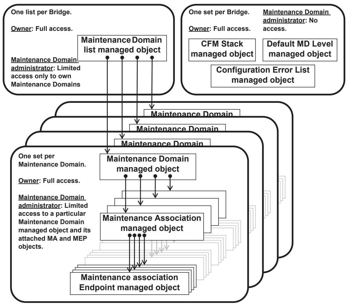
Figure 12-1—Relationships among CFM managed objects
12.14.1 Maintenance Domain list managed object
There is one Maintenance Domain list managed object per Bridge. It contains a list of the Maintenance Domains that have been configured on the Bridge.
The management operations that can be performed on the Maintenance Domain list managed object are as follows:
a) Read Maintenance Domain list (12.14.1.1)
b) Create Maintenance Domain managed object (12.14.1.2)
c) Delete Maintenance Domain managed object (12.14.1.3)
NOTE—In Provider Bridge applications, each Maintenance Domain, and thus each Maintenance Domain managed object, can be controlled by a different administrative organization. Some or all of these administrative organizations can be different from that which controls the Maintenance Domain list managed object or the managed objects in Clause 12 other than those in 12.14. See 17.3.9 for a discussion of the means by which control of and access to different instances of the Maintenance Domain managed object are allocated to these different administrative organizations.
12.14.1.1 Read Maintenance Domain list
12.14.1.1.1 Purpose
To obtain information about all of the Maintenance Domains in a Bridge.
12.14.1.1.2 Inputs
None.
12.14.1.1.3 Outputs
a) A list, perhaps empty, of the Maintenance Domain managed objects configured on the Bridge. For each item in the list, the Read Maintenance Domain list command returns:
1) A Maintenance Domain Name, including the format specifier from Table 21-19 (21.6.5.1)
2) A reference to that Maintenance Domain’s Maintenance Domain managed object (12.14.5)
12.14.1.2 Create Maintenance Domain managed object
12.14.1.2.1 Purpose
To create a new Maintenance Domain managed object in a Bridge, and add it to the Bridge’s Maintenance Domain list managed object.
12.14.1.2.2 Inputs
a) A Maintenance Domain Name, including the format specifier from Table 21-19 (21.6.5.1); default value is the character string (format 4) “DEFAULT.”
b) The MD Level at which the Maintenance Domain is to be created; default value is 0.
12.14.1.2.3 Outputs
a) Operation status. This takes one of the following values:
1) Operation rejected due to invalid Maintenance Domain Name (21.6.5.1);
2) Operation rejected because Maintenance Domain Name already exists;
3) Operation rejected due to invalid MD Level; or
4) Operation accepted.
12.14.1.3 Delete Maintenance Domain managed object
12.14.1.3.1 Purpose
To delete a specific Maintenance Domain managed object from a Bridge and from the Bridge’s Maintenance Domain list managed object.
12.14.1.3.2 Inputs
a) A reference to a particular Maintenance Domain managed object (12.14.5).
12.14.1.3.3 Outputs
a) Operation status. This takes one of the following values:
1) Operation rejected due to invalid or nonexistent Maintenance Domain; or
2) Operation accepted.
12.14.2 CFM Stack managed object
There is one CFM Stack managed object per Bridge. It permits retrieval of information about the MPs configured on a particular Bridge Port or aggregated port. The management operation that can be performed is
a) Read CFM Stack managed object (12.14.2.1)
12.14.2.1 Read CFM Stack managed object
12.14.2.1.1 Purpose
To obtain the contents of the CFM Stack managed object, which allows a network administrator to discover the relationships among MEPs and MHFs configured on a particular Bridge Port or aggregated port.
12.14.2.1.2 Inputs
a) An interface, either a Bridge Port, or an aggregated IEEE 802.3 port within a Bridge Port, on which MPs might be configured.
b) An MD Level.
c) A value indicating the direction in which any reported MP faces, either
1) Down (Active SAP is further away from the Frame filtering entity); or
2) Up (Active SAP is closer to the Frame filtering entity).
d) A specific VID, I-SID, Traffic Engineering service instance Identifier (TE-SID), or Segment Identifier (SEG-ID) associated with an MP, or 0, in the case that the MP is associated with no VID, I-SID, TE-SID, or SEG-ID.
12.14.2.1.3 Outputs
a) Operation status. This takes one of the following values:
1) Operation rejected due to illegal inputs;
2) No MP is configured on the indicated Bridge Port or aggregated port at the indicated MD Level and direction;
3) A MEP is configured; or
4) An MHF is configured.
b) Either the Maintenance Domain managed object (12.14.5) to which the MP’s MA is associated, or an indication that there is no Maintenance Domain associated with the MP.
c) Either the Maintenance Association managed object (12.14.6) to which the MP is associated, or an indication that there is no MA associated with the MP.
d) If a MEP is configured, its MA Endpoint Identifier (MEPID), else 0.
e) The MAC address of the MP.
12.14.3 Default MD Level managed object
There is a single Default MD Level managed object per Bridge component. It controls MIP Half Function (MHF) creation for VIDs or I-SIDs of I- or B-components that are not contained in the list of VIDs attached to any specific Maintenance Association managed object [item c) in 12.14.5.3.2], and the transmission of the Sender ID TLV (21.5.3) by those MHFs.
The management commands that can be performed on the Default MD Level managed object are as follows:
a) Read Default MD Level managed object (12.14.3.1).
b) Write Default MD Level managed object (12.14.3.2).
12.14.3.1 Read Default MD Level managed object
12.14.3.1.1 Purpose
To read the table of default parameters for controlling MHFs not associated with any MA configured on the Bridge component.
12.14.3.1.2 Input
a) A VID or I-SID in an I- or B-component.
12.14.3.1.3 Output
a) A list of VIDs associated with any MHF on the VID named in item a) in 12.14.3.1.2, always including that VID, or the Backbone-SID of the B-component or VIP-SID of the I-component associated with any MHF on the I-SID named in item a) in 12.14.3.1.2. The first VID is the MAs’ Primary VID. List is empty if no VID specified in 12.14.3.1.2.
b) A Boolean value indicating whether this entry is in effect or has been overridden by the existence of a Maintenance Association managed object associated with the same VID or I-SID of I- or Bcomponents and MD Level, and on which is configured an Up MEP. True if this Maintenance Domain managed object is in effect.
c) (writable) The MD Level at which MHFs are to be created.
d) (writable) An enumerated value indicating whether the management entity can create MHFs for this VID(s) or I-SID(s) of I- or B-components: defMHFnone: (n, the default), defMHFdefault (o), or defMHFexplicit (p) (22.2.3).
e) (writable) An enumerated value indicating what, if anything, is to be included in the Sender ID TLV (21.5.3) transmitted by MPs configured in the Default Maintenance Domain: sendIdNone (1, the default value), sendIdChassis (2), sendIdManage (3), or sendIdChassisManage (4).
12.14.3.2 Write Default MD Level managed object
12.14.3.2.1 Purpose
To write entries in the table of default parameters for controlling MHFs on VIDs or on I-SIDs used in an Ior B-component not associated with any MA.
12.14.3.2.2 Inputs
a) A list of VIDs or the VIP-SIDs used in the I-component or Backbone-SID used in the B-component, or 0, indicating no VID or I-SID. The first VID in the list is the Primary VID.
b) One of the writable managed object in 12.14.3.1.3.
12.14.3.2.3 Outputs
a) Operation status. This takes one of the following values:
1) Operation rejected because creating or assigning these VIDs or I-SIDs to this MD Level would exceed the number of MD Levels supported by some Bridge Port (item c) in 22.2.4);
2) Operation rejected because the VID list provided [item a) in 12.14.3.2.2] specifies a different Primary VID, or contains one or more but not all of the VIDs, in the definition of an MA or some other entry in the Default MD Level managed object; or
3) Operation accepted.
12.14.4 Configuration Error List managed object
The Configuration Error List managed object is a list of {identifier, port} pairs configured in error together with the identity of the configuration error. The identifier is a VID, I-SID, TE-SID, or SEG-ID and the port is a simple Bridge Port or aggregated Bridge Port.
12.14.4.1 Read Configuration Error List managed object
12.14.4.1.1 Purpose
To list the entries in the Configuration Error List where each entry describes the identifier and port pair that identifies the entry, together with a description of the particular configuration error.
12.14.4.1.2 Inputs
a) A VID, I-SID, or TE-SID, specifying which service instance to check for ports in error or a SEG-ID specifying which Infrastructure Segment to checkfor ports in error.
b) An interface, either a Bridge Port or an aggregated IEEE 802.3 port within a Bridge Port.
12.14.4.1.3 Outputs
a) An indication of the result of the operation:
1) Operation rejected due to illegal vlan_identifier;
2) Operation rejected due to illegal or nonexistent Bridge Port or aggregated port; or
3) Operation accepted.
b) If the operation was accepted, a vector of Boolean error conditions from 22.2.4, any of which may be true:
1) CFMleak
2) ConflictingVIDs
3) ExcessiveLevels and/or
4) OverlappedLevels
12.14.5 Maintenance Domain managed object
There can be any number of Maintenance Domain managed objects per Bridge. A Maintenance Domain managed object is required in order to create an MA with a Maintenance Association Identifier (MAID) that includes that Maintenance Domain’s Name. From this Maintenance Domain managed object, all Maintenance Association managed objects associated with that Maintenance Domain managed object can be accessed, and thus controlled.
The management operations that can be performed on the Maintenance Domain managed object are as follows:
a) Read Maintenance Domain managed object (12.14.5.1)
b) Write Maintenance Domain managed object (12.14.5.2)
c) Create Maintenance Association managed object (12.14.5.3)
d) Delete Maintenance Association managed object (12.14.5.4)
NOTE 1—The Maintenance Domain managed object is defined in such a manner that it can be configured identically in all of the Bridges in that Bridged Network. All of the information local to a particular MA or a particular Bridge is contained in other managed objects, e.g., the Maintenance Association managed object (12.14.6) or the Maintenance association Endpoint managed object (12.14.7).
NOTE 2—A single Maintenance Domain managed object can be used to manage any number of separate Maintenance Domains, as Maintenance Domains are defined in 18.1. For example, the Maintenance Association managed object for all of the physical links in a Bridged Network that are protected by MAs can be grouped together under a single Maintenance Domain managed object for the convenience of the network administrator.
NOTE 3—Multiple Maintenance Domain managed objects can be used to manage a single Maintenance Domain, as Maintenance Domains are defined in 18.1. For example, a PBN’s Domain Service Access Points (DoSAPs) could be split among two Maintenance Domain managed objects, one for point-to-point services and one for multipoint services.
12.14.5.1 Read Maintenance Domain managed object
12.14.5.1.1 Purpose
To obtain information from a Bridge about a specific Maintenance Domain managed object.
12.14.5.1.2 Inputs
a) A reference to a particular Maintenance Domain managed object (12.14.5).
12.14.5.1.3 Outputs
a) Operation status. This takes one of the following values:
1) Operation rejected due to nonexistent Maintenance Domain; or 2) Operation accepted.
b) The MD Level of the specific Maintenance Domain identified by the Input.
c) (writable) An enumerated value indicating whether the management entity can create MHFs for this Maintenance Domain: defMHFnone: (n, the default value), defMHFdefault (o), or defMHFexplicit (p) (22.2.3).
d) (writable) An enumerated value indicating what, if anything, is to be included in the Sender ID TLV (21.5.3) transmitted by MPs configured in this Maintenance Domain: sendIdNone (1, the default value), sendIdChassis (2), sendIdManage (3), or sendIdChassisManage (4) [item d) in 12.14.6.1.3].
e) (writable) The network address to which Fault Alarms (12.14.7.7) are to be transmitted, or a value indicating “Fault Alarms are not to be transmitted.” Default value is “not transmitted.”
NOTE—The variables c) through e) could be writable by the organization operating the Maintenance Domain.
f) A list of references to the Maintenance Association managed objects (12.14.6) attached to the indicated Maintenance Domain managed object.
12.14.5.2 Write Maintenance Domain managed object
12.14.5.2.1 Purpose
To alter a value of a specific Maintenance Domain managed object.
12.14.5.2.2 Inputs
a) A reference to a particular Maintenance Domain managed object (12.14.5).
b) A reference to a writable managed object in 12.14.5.1.3 to be altered.
c) A new value for the managed object.
12.14.5.2.3 Outputs
a) Operation status. This takes one of the following values:
1) Operation rejected due to nonexistent Maintenance Domain;
2) Operation rejected due to the selected managed object being Read-Only;
3) Operation rejected due to invalid value for the selected managed object; or
4) Operation accepted.
12.14.5.3 Create Maintenance Association managed object
12.14.5.3.1 Purpose
To create a new Maintenance Association managed object within a Maintenance Domain managed object.
12.14.5.3.2 Inputs
a) A reference to a particular Maintenance Domain managed object (12.14.5).
b) The Short MA Name of an MA within that Maintenance Domain, including the format specifier from Table 21-20 (21.6.5.4). In the case of a PBB-TE, VID-based, or Infrastructure Segment MA, the default value is a 2-octet integer (format 3) containing the primary VID, or 0, if the MA is not attached to a VID.
c) The list of VIDs, the I-SID, the TE-SID, or the SEG-ID monitored by this MA, or 0, if the MA is not attached to any VID, I-SID, TE-SID, or SEG-ID. In the case that a list of VIDs is specified, the first VID in the list is the MA’s Primary VID (default none). The specification of I-SID is allowed only in the case of I- or B-components. The TE-SID is allowed only in the case that PBB-TE or SPBM is supported. The SEG-ID is allowed only in the case that IPS is supported.
12.14.5.3.3 Outputs
a) Operation status. This takes one of the following values:
1) Operation rejected due to nonexistent Maintenance Domain;
2) Operation rejected due to invalid Short MA Name (21.6.5.4);
Operation rejected due to the existence of another MA in the same Maintenance Domain with the same Short MA Name;
4) Operation rejected because creation of this MA would exceed the number of MD Levels supported by some Bridge Port [item c) in 22.2.4];
5) Operation rejected because the VID list provided [item c) in 12.14.5.3.2] specifies a different Primary VID, or contains one or more, but not all, of the VIDs, in the definition of another MA or an entry in the Default MD Level managed object;
6) Operation rejected because the I-SID value specified does not correspond to a valid backbone service instance;
Operation rejected because the TE-SID value specified does not correspond to a valid TESI or set of SPBM path endpoints;
8) Operation rejected because the SEG-ID value specified does not correspond to a valid Infrastructure Segment; or
9) Operation accepted.
12.14.5.4 Delete Maintenance Association managed object
12.14.5.4.1 Purpose
To delete a specific Maintenance Association managed object from a Maintenance Domain managed object.
12.14.5.4.2 Inputs
a) A reference to a particular Maintenance Association managed object (12.14.6).
12.14.5.4.3 Outputs
a) Operation status. This takes one of the following values:
1) Operation rejected due to nonexistent MA; or
2) Operation accepted.
12.14.6 Maintenance Association managed object
There can be any number of Maintenance Association managed objects per Bridge, one for each service instance for which an MP is defined on that Bridge. From this Maintenance Association managed object, all Maintenance association Endpoint managed objects associated with that Maintenance Association managed object can be accessed, and thus controlled.
The management operations that can be performed on the Maintenance Association managed object are as follows:
a) Read Maintenance Association managed object (12.14.6.1)
b) Write Maintenance Association managed object (12.14.6.2)
c) Create Maintenance association Endpoint managed object (12.14.6.3)
d) Delete Maintenance association Endpoint managed object (12.14.6.4)
NOTE 1—The Maintenance Association managed object is defined in such a manner that it can be configured identically in all of the Bridges in its Maintenance Domain. All information local to a particular Bridge is contained in other managed objects, e.g., the Maintenance association Endpoint managed object (12.14.7).
NOTE 2—Although MHFs are created via the Maintenance Domain managed object, the Default MD Level managed object, and the Maintenance Association managed object, and although there is a Maintenance association Endpoint managed object, there is no “MIP Half Function managed object.” One reason for this omission is that no controls over the behavior of the MHF beyond its existence is required. Another is that the burden of implementing, providing access to, and providing the maintenance capabilities to access the counters and similar managed objects appropriate to an MHF Managed Object seemed to the developers of this standard to outweigh the benefits of having that information available.
12.14.6.1 Read Maintenance Association managed object
12.14.6.1.1 Purpose
To obtain information from a Bridge about a specific Maintenance Association managed object.
12.14.6.1.2 Inputs
a) A reference to a particular Maintenance Association managed object (12.14.6).
12.14.6.1.3 Outputs
a) Operation status. This takes one of the following values:
1) Operation rejected due to nonexistent MA; or 2) Operation accepted.
The VID(s), I-SID, TE-SID, or SEG-ID monitored by this MA, or 0, if the MA is not attached to any VID, I-SID, TE-SID, or SEG-ID. In the case of a list of VIDs, the first VID returned is the MA’s Primary VID.
c) (writable) An enumerated value indicating whether the management entity can create MHFs for this MA: defMHFnone: (n), defMHFdefault (o), defMHFexplicit (p), or defMHFdefer (q), (22.2.3), default value is defMHFdefer.
d) (writable) An enumerated value indicating what, if anything, is to be included in the Sender ID TLV (21.5.3) transmitted by MPs configured in this MA:
1) sendIdNone: The Sender ID TLV is not to be sent; 2) sendIdChassis: The Chassis ID Length, Chassis ID Subtype, and Chassis ID fields of the Sender ID TLV are to be sent, but not the Management Address Length or Management Address fields;
3) sendIdManage: The Management Address Length and Management Address of the Sender ID TLV are to be sent, but the Chassis ID Length is to be transmitted with a 0 value, and the Chassis ID Subtype and Chassis ID fields not sent;
4) sendIdChassisManage: The Chassis ID Length, Chassis ID Subtype, Chassis ID, Management Address Length, and Management Address fields are all to be sent; or
5) sendIdDefer: (the default value) The contents of the Sender ID TLV are determined by the Maintenance Domain managed object, item d) in 12.14.5.1.3.
e) (writable) An enumerated value, other than 0, indicating the interval between CCM transmissions to be used by all MEPs in the MA (20.8.1, 21.6.1.3) (default 1 s).
f) (writable) The network address to which Fault Alarms (12.14.7.7) are to be transmitted, a value indicating “not specified,” or a value indicating “Fault Alarms are not to be transmitted.” If “not specified,” the address used is that from the Maintenance Domain managed object [item e) in 12.14.5.1.3].
g) (writable) A list of the MEPIDs of the MEPs in the MA.
12.14.6.2 Write Maintenance Association managed object
12.14.6.2.1 Purpose
To alter a value of a specific Maintenance Association managed object.
12.14.6.2.2 Inputs
a) A reference to a particular Maintenance Association managed object (12.14.6).
b) A reference to one of the writable managed objects in 12.14.6.1.3 is to be altered.
c) A new value for the managed object.
12.14.6.2.3 Outputs
a) Operation status. This takes one of the following values:
1) Operation rejected due to nonexistent MA;
2) Operation rejected due to the selected managed object being Read-Only;
3) Operation rejected due to lack of authority to set this variable;
4) Operation rejected due to invalid value for the selected managed object; or
5) Operation accepted.
12.14.6.3 Create Maintenance association Endpoint managed object
12.14.6.3.1 Purpose
To create a new Maintenance association Endpoint managed object within a Maintenance Association managed object on a specific Bridge Port or aggregated port.
12.14.6.3.2 Inputs
a) A reference to a particular Maintenance Association managed object (12.14.6).
b) A MEPID for the created MEP.
c) A value indicating the direction in which the MEP faces on the Bridge Port or aggregated port, either 1) Down (Active SAP is further away from the Frame filtering entity) (the default); or 2) Up (Active SAP is closer to the Frame filtering entity).
d) An interface, either a Bridge Port or an aggregated IEEE 802.3 port within a Bridge Port.
12.14.6.3.3 Outputs
a) Operation status. This takes one of the following values:
1) Operation rejected due to nonexistent MA;
2) Operation rejected because the specified MEPID already exists in this MA in this Bridge;
3) Operation rejected because MEPID is not in the MA’s list of MEPIDs [item g) in 12.14.6.1.3];
4) Operation rejected due to the existence of a MEP in the same direction (Up or Down) at that same MD Level, for the same VID(s), I-SID, TE-SID, or SEG-ID as this MEP (or for no VID, I-SID, TE-SID, or SEG-ID, if this MEP’s MA has no VID, I-SID, TE-SID, or SEG-ID), on that Bridge Port or aggregated port;
5) Operation failed because one or more of the listed VIDs, I-SID, or TE-SID in this MA are assigned to some other MA on which Up MEPs are configured on any Bridge Port;
6) Operation rejected because the Bridge is incapable of instantiating a MEP on that Bridge Port or aggregated IEEE 802.3 port;
7) Operation rejected because an Up MEP cannot be configured for an MA that has no VID, I-SID, or TE-SID;
8) Operation rejected because a MEP exists on this MA that has a different value for its Up/Down parameter [item c) in 12.14.6.3.2]; or
9) Operation accepted.
12.14.6.4 Delete Maintenance association Endpoint managed object
12.14.6.4.1 Purpose
To delete an existing Maintenance association Endpoint managed object from a Maintenance Association managed object.
12.14.6.4.2 Inputs
a) A reference to a particular Maintenance association Endpoint managed object (12.14.7).
12.14.6.4.3 Outputs
a) Operation status. This takes one of the following values:
1) Operation rejected due to nonexistent MEP; or
2) Operation accepted.
12.14.7 Maintenance association Endpoint managed object
There can be any number of Maintenance association Endpoint managed objects per Bridge, one for each MEP defined within that Bridge. From this Maintenance association Endpoint managed object, all management objects related to that MEP can be controlled.
The management operations that can be performed on the Maintenance association Endpoint managed object are as follows:
a) Read Maintenance association Endpoint managed object (12.14.7.1)
b) Write Maintenance association Endpoint managed object (12.14.7.2)
c) Transmit Loopback Messages (12.14.7.3)
d) Transmit Linktrace Message (12.14.7.4)
e) Read Linktrace Reply (12.14.7.5)
f) Read MEP Database (12.14.7.6)
g) Transmit MEP Fault Alarm (12.14.7.7)
12.14.7.1 Read Maintenance association Endpoint managed object
12.14.7.1.1 Purpose
To obtain information from a Bridge about a specific Maintenance association Endpoint managed object.
12.14.7.1.2 Inputs
a) A reference to a particular Maintenance association Endpoint managed object (12.14.7).
12.14.7.1.3 Outputs
a) Operation status. This takes one of the following values:
1) Operation rejected due to nonexistent MEP; or 2) Operation accepted.
b) An interface, either a Bridge Port or an aggregated IEEE 802.3 port within a Bridge Port, to which the MEP is attached.
c) A value indicating the direction in which the MEP faces on the interface, either
1) Down (Active SAP is further away from Frame filtering entity); or 2) Up (Active SAP is closer to the Frame filtering entity).
d) (writable) An integer indicating the Primary VID of the MEP, always one of the VIDs assigned to the MEP’s MA. The value 0 indicates either that the Primary VID is that of the MEP’s MA or that the MEP’s MA is associated with no VID. In the case of a PBB-TE associated MEP, the Primary VID is not writable but is always associated with the value of the ESP-VID parameter identifying the MA’s ESP that has the MEP’s MAC address in its ESP-SA field (MEPprimaryVID, 20.9.7). In the case of an Infrastructure Segment associated MEP, the Primary VID (MEPprimaryVID, 20.9.7) is not writable but is always associated with the value of the SMP-VID parameter identifying the MA’s SMP that has the MEP’s MAC address in its SMP-SA field. In the case of an SPB associated MEP, the Primary VID is not writable but is always associated with the value of the SPVID for the node on which the MEP is configured (for SPBV) or the Base VID (for SPBM).
e) (writable) A Boolean flag indicating the administrative state of the MEP (20.9.1) (default FALSE).
f) A value indicating the current state of the MEP Fault Notification Generator state machine (20.37).
g) (writable) A Boolean flag indicating whether the MEP is or is not to generate CCMs (CCIenabled, 20.10.1) (default FALSE, no CCMs).
h) (writable) The priority parameter for CCMs and LTMs transmitted by the MEP (default value: the highest priority, i.e., that with the highest numerical value, allowed to pass through the Bridge Port for any of this MEP’s VIDs, I-SID, TE-SID, or SEG-ID).
NOTE—The management entity can obtain the default value for this variable from the Priority regeneration table in 6.9.3 by extracting the highest priority value in the table on this MEP’s Bridge Port (1 is lowest, then 2, then 0, then 3–7), appropriate to the direction in which frames are emitted from the MEP’s Active SAP.
i) The MAC address of the MEP (19.4). In the case of a MEP that is associated with a TESI, the MAC address of the CBP upon which the MEP is operating. In the case of a MEP that is associated with an Infrastructure Segment, the MAC address of the PNP upon which the MEP is operating.
j) (writable) The network address to which Fault Alarms (12.14.7.7) are to be transmitted, a value indicating “not specified,” or a value indicating “Fault Alarms are not to be transmitted.” If “not specified,” the address used is that from the Maintenance Association managed object [item f) in 12.14.6.1.3].
k) (writable) An integer value specifying the lowest priority defect that is allowed to generate a Fault Alarm (20.9.5):
1) All defects: DefRDICCM, DefMACstatus, DefRemoteCCM, DefErrorCCM, and DefXconCCM;
2) Only DefMACstatus, DefRemoteCCM, DefErrorCCM, and DefXconCCM (the default);
3) Only DefRemoteCCM, DefErrorCCM, and DefXconCCM;
4) Only DefErrorCCM and DefXconCCM;
5) Only DefXconCCM; or
6) No defects are to be reported.
l) (writable) The time that defects must be present before a Fault Alarm is issued (20.35.3) (default 2.5 s).
m) (writable) The time that defects must be absent before resetting a Fault Alarm (20.35.4) (default 10 s).
n) An enumerated value indicating the highest priority defect that has been present since the MEP Fault Notification Generator state machine was last in the FNG_RESET state (20.35.9):
1) DefNone: No defect has been present since the last FNG_RESET state;
2) DefRDICCM: The last CCM received by this MEP from some remote MEP contained the RDI bit, so variable item o) in 12.14.7.1.3 is set;
3) DefMACstatus: The last CCM received by this MEP from some remote MEP indicated that the transmitting MEP’s associated MAC is reporting an error status via the Port Status TLV (21.5.4) or Interface Status TLV (21.5.5), so variable item p) in 12.14.7.1.3 is set;
4) DefRemoteCCM: This MEP is not receiving CCMs from some other MEP in its configured list [item g) in 12.14.6.1.3], so variable item q) in 12.14.7.1.3 is set;
5) DefErrorCCM: This MEP is receiving invalid CCMs, so variable item r) in 12.14.7.1.3, is set; or
6) DefXconCCM: This MEP is receiving CCMs that could be from some other MA, so variable item s) in 12.14.7.1.3 is set.
o) A Boolean flag (20.35.7) indicating that some other MEP in this MEP’s MA is transmitting the RDI bit (can trigger DefRDICCM).
p) A Boolean flag (20.35.6) indicating that a Port Status TLV (21.5.4) or Interface Status TLV (21.5.5) is indicating an error condition (can trigger DefMACstatus).
q) A Boolean flag (20.35.5) indicating that CCMs are not being received from at least one of the configured remote MEPs (can trigger DefRemoteCCM).
r) A Boolean flag (20.21.3) indicating that erroneous CCMs are being received from some MEP in this MEP’s MA (can trigger DefErrorCCM).
s) A Boolean flag (20.23.3) indicating that CCMs are being received from a MEP that could be in some other MA (can trigger DefXconCCM).
t) The last-received CCM (20.21.2) that triggered a DefErrorCCM fault (20.21.3).
u) The last-received CCM (20.23.2) that triggered a DefXconCCM fault (20.23.3).
v) (optional) The total number of out-of-sequence CCMs received (20.16.12).
w) The total number of CCMs transmitted (20.10.2).
x) The next Loopback Transaction Identifier to be sent in an LBM (20.30.2).
y) The total number of valid, in-order LBRs received (20.33.1).
z) The total number of valid, out-of-order LBRs received (20.33.1).
aa) (optional) The total number of LBRs received whose mac_service_data_unit did not match (except for the OpCode) that of the corresponding LBM (20.2.3).
ab) The next LTM Transaction Identifier to be sent in an LTM (20.41.1).
ac) The total number of unexpected LTRs received (20.44.1).
ad) The total number of LBRs transmitted (20.28.2).
(writable) A list indicating which of the remote MEPs in the same MA are active. The Remote MEP state machines (20.20) are instantiated only for the active remote MEPs. By default, all configured remote MEPs in the same MA are active.
af) (writable) Only applicable for PBB-TE MEPs supporting the Traffic field (21.6.1.4), a Boolean flag indicating that the capability to report the presence of traffic is enabled. The default value is FALSE.
ag) (writable) Only applicable for PBB-TE MEPs supporting the Traffic field (21.6.1.4), a Boolean flag indicating that the mismatch defect is allowed to generate a Fault Alarm. The default value is FALSE.
ah) Only applicable for PBB-TE MEPs supporting the Traffic field (21.6.1.4), a Boolean flag indicating the presence of a traffic field mismatch defect (20.25.2) (can trigger DefMmCCM).
ai) Only applicable for PBB-TE MEPs supporting the Traffic field (21.6.1.4), a Boolean flag indicating the presence of a local mismatch defect (20.25.5) (can trigger DefMmCCM).
aj) Only applicable for PBB-TE MEPs supporting the Traffic field (21.6.1.4), an enumerated value indicating if the mismatch defect that has been present since the MEP Mismatch Fault Notification Generator state machine (20.40) was last in the MFNG_RESET state, either
1) DefNone: No defect has been present since the last MFNG_RESET state; or
2) DefMmCCM: This MEP is receiving CCMs that have different value in their Traffic field than the CCMs transmitted by this MEP or is transmitting CCMs with both the RDI and the Traffic field bit set to 1 and the disableLocdefect (20.25.4) variable is cleared, so variable item ah) in 12.14.7.1.3 is set.
ak) Only applicable for PBB-TE MEPs supporting the Traffic field (21.6.1.4), a value indicating the current state of the MEP Mismatch Fault Notification Generator state machine (20.40).
al) (writable) Only applicable for ECMP path MEPs, a list of flow hash values to be used in a path testing cycle (20.10.5).
12.14.7.2 Write Maintenance association Endpoint managed object
12.14.7.2.1 Purpose
To alter a value in a specific managed object within a specific Maintenance association Endpoint managed object.
12.14.7.2.2 Inputs
a) A reference to a particular Maintenance association Endpoint managed object (12.14.7).
b) A reference to one of the writable managed objects in 12.14.7.1.3 is to be altered.
c) A new value for the managed object.
12.14.7.2.3 Outputs
a) Operation status. This takes one of the following values:
1) Operation rejected due to nonexistent MEP;
2) Operation rejected due to the selected managed object being Read-Only;
3) Operation rejected due to invalid value for the selected managed object; or
4) Operation accepted.
12.14.7.3 Transmit Loopback Messages
12.14.7.3.1 Purpose
To signal to the MEP to transmit some number of LBMs.
NOTE—The Maintenance association Endpoint managed object (12.14.7) can be examined to determine whether the corresponding LBRs have been received by the MEP.
12.14.7.3.2 Inputs
a) A reference to a particular Maintenance association Endpoint managed object (12.14.7).
b) An indication of the target MAC address for LBMs transmitted by the MEP (20.31.1):
1) The MEPID of a MEP in that MA; or
2) An Individual destination MAC address; or
3) For PBB-TE and SPBM VID MEPs, an individual MAC address to be used as the MIP MAC address in a PBB-TE MIP TLV.
c) The number of LBMs to be transmitted (default 1).
d) An arbitrary amount of data to be included in a Data TLV, along with an indication whether the Data TLV is to be included (20.31.1) (default no Data TLV).
e) The priority and drop_eligible parameters to be used in the transmitted LBMs [default is CCM priority item h) in 12.14.7.1.3, drop_eligible FALSE].
f) In the case of a PBB-TE MEP, the Reverse VID to be used in the associated PBB-TE MIP TLV (21.7.5). The parameter is not required in the case of PBB-TE MEPs associated with point-to-point TESIs or if the b3) entry is a MAC address corresponding to an entry in the ESP-DA field of any of the MA’s ESPs.
g) In the case of an SPBM VID MEP, an individual or group MAC address to be used as the destination_address for the LBM primitive. If no value is provided the group MAC address for the SPBM default I-SID (Table 9-3, Figure 27-3) is used.
h) In the case of ECMP with flow filtering, a flow hash value if the destination address is an individual address.
12.14.7.3.3 Outputs
a) An indication of whether the command was accepted by the MEP:
1) Operation rejected due to nonexistent MEP;
2) Operation rejected due to invalid number of LBMs to be transmitted;
3) Operation rejected due to too much data to be transmitted;
4) Operation rejected due to invalid priority or drop_eligible parameters to be transmitted;
5) Operation rejected due to invalid ESP-VID;
6) The LBM(s) will be (or have been) sent; or
7) The LBM(s) will not be sent (e.g., because the Bridge is busy with another LBM transmit operation).
b) The Loopback Transaction Identifier (20.30.2) of the first LBM (to be) sent. The value returned is undefined if the Transmit Loopback Messages command was not accepted.
12.14.7.4 Transmit Linktrace Message
12.14.7.4.1 Purpose
To signal to the MEP to transmit an LTM and to create an LTM entry in the MEP’s Linktrace Database.
NOTE—The Maintenance association Endpoint managed object (12.14.7) can be examined to determine whether the corresponding LTRs have been received by the MEP.
12.14.7.4.2 Inputs
a) A reference to a particular Maintenance association Endpoint managed object (12.14.7).
b) The Flags field for LTMs transmitted by the MEP (20.42.1).
c) An indication of the Target MAC Address field to be transmitted, either
1) The MEPID of another MEP in the same MA; or
2) An individual MAC address.
d) An initial value for the LTM TTL field (21.8.4). Default value, if not specified, is 64.
e) In the case of a PBB-TE MEP, the Reverse VID to be used in the associated PBB-TE MIP TLV (21.7.5). The parameter is not required in the case of PBB-TE MEPs associated with point-to-point TESIs.
f) In the case of an SPBM VID MEP, an individual or group MAC address to be used as the destination_address for the LTM primitive. If no value is provided the group MAC address for the SPBM default I-SID (Table 9-3, Figure 27-3) is used.
g) In the case of ECMP with flow filtering, a flow hash value if the destination address is an Individual address.
12.14.7.4.3 Outputs
a) An indication of whether the command was accepted by the MEP:
1) Operation rejected due to nonexistent MEP;
2) Operation rejected due to invalid Flags field to be transmitted;
3) Operation rejected due to invalid Target MAC Address to be transmitted;
4) Operation rejected due to invalid LTM TTL field to be transmitted;
5) Operation rejected due to invalid ESP-VID;
6) The command was accepted and the LTM has (or will be) transmitted; or
7) The command was rejected and no LTM will be sent (e.g., because the Bridge is busy with another LTM transmit operation).
b) The LTM Transaction Identifier (20.41.1) of the LTM sent. The value returned is undefined if the Transmit Linktrace Message command was not accepted.
c) The LTM Egress Identifier TLV value transmitted in the LTM. The value returned is undefined if the Transmit Linktrace Message command was not accepted.
12.14.7.5 Read Linktrace Reply
12.14.7.5.1 Purpose
To obtain from the MEP’s Linktrace database (20.41.2) the LTM entry for a previously transmitted LTM with a specific LTM Transaction Identifier. An LTM entry consists of a list of LTR entries, each corresponding to a Linktrace Reply (LTR) PDU received in response to that LTM. The LTM Transaction Identifier returned by successful Transmit Linktrace Message command [item b) in 12.14.7.4.3] is used in the Read Linktrace Reply command [item b) in 12.14.7.5.2] to select the LTM entry.
See J.5 for a discussion of how to interpret the output from the Read Linktrace Reply command.
12.14.7.5.2 Inputs
a) A reference to a particular Maintenance association Endpoint managed object (12.14.7).
b) The LTM Transaction Identifier returned from a previous Transmit Linktrace Message command, indicating the LTM entry to which the LTR entries will be attached.
c) An index to distinguish among multiple LTRs with the same LTR Transaction Identifier field value.
12.14.7.5.3 Outputs
A list of LTR entries returned corresponding to the selected LTM Transaction Identifier (20.41.2). Each LTR entry in the list returns:
a) An indication of whether the command was accepted by the MEP:
1) Operation rejected due to nonexistent MEP;
2) Operation rejected due to LTM Transaction Identifier not found;
3) Operation rejected due to LTR entry has been discarded because too many LTRs have been returned corresponding to that LTM Transaction Identifier;
4) Operation rejected due to LTR entry with that index has not yet been returned; or
5) Operation accepted.
b) The integer Reply TTL field value returned in the LTR (20.41.2.2).
c) A Boolean value stating whether an LTM was forwarded by the responding MP, as returned in the FwdYes flag of the Flags field (20.41.2.1).
d) A Boolean value stating whether the forwarded LTM reached a MEP enclosing its MA, as returned in the TerminalMEP flag of the Flags field (20.41.2.1).
e) An octet string holding the Last Egress Identifier field returned in the LTR Egress Identifier TLV of the LTR (20.41.2.3).
f) An octet string holding the Next Egress Identifier field returned in the LTR Egress Identifier TLV of the LTR (20.41.2.4).
g) An enumerated value indicating the value returned in the Relay Action field (20.41.2.5): RlyHit, RlyFDB, or RlyMPDB.
h) (if returned in the LTR) An enumerated value indicating the format of the Chassis ID (21.5.3.2).
i) (if returned in the LTR) The Chassis ID (21.5.3.3).
j) (if returned in the LTR) The Management Address information of the Bridge transmitting the LTR (21.5.3.7).
k) (if returned in the LTR) An enumerated value indicating the value returned in the Ingress Action field (20.41.2.6) of the LTR: IngOK, IngDown, IngBlocked, or IngVID.
l) (if returned in the LTR) The MAC address returned in the Ingress MAC Address field (20.41.2.7).
m) (if returned in the LTR) An enumerated value indicating the format of the Ingress Port ID field (20.41.2.8).
n) (if returned in the LTR) The Ingress Port ID (20.41.2.9).
o) (if returned in the LTR) An enumerated value indicating the value returned in the Egress Action field (20.41.2.10) of the LTR: EgrOK, EgrDown, EgrBlocked, or EgrVID.
p) (if returned in the LTR) The MAC address returned in the Egress MAC Address field (20.41.2.11).
q) (if returned in the LTR) An enumerated value indicating the format of the Egress Port ID (20.41.2.12).
r) (if returned in the LTR) The Egress Port ID (20.41.2.13).
s) (if returned in the LTR) The OUI or CID and contents of any Organization-Specific TLVs (21.5.2) returned in the LTR.
12.14.7.6 Read MEP Database
12.14.7.6.1 Purpose
To obtain from the MEP the contents of one element in the MEP CCM Database.
12.14.7.6.2 Inputs
a) A reference to a particular Maintenance association Endpoint managed object (12.14.7).
b) The MEPID of a remote MEP whose information from the selected database is to be returned.
12.14.7.6.3 Outputs
a) An indication of whether the command was accepted by the MEP:
1)2) Operation rejected due to nonexistent MEP; Operation rejected due remote MEPID not configured in MA; or 3) Operation accepted.
b) An enumerated value indicating the operational state of the Remote MEP state machine (20.20) for this remote MEP:
1) RMEP_IDLE; 2) RMEP_START; 3) RMEP_FAILED; or 4) RMEP_OK.
c) The time (SysUpTime, IETF RFC 3418) at which the Remote MEP state machine last entered either the RMEP_FAILED or RMEP_OK state, or 0 if it has not yet entered either of those states.
d) The MAC address of the remote MEP (the source_address of the last received CCM) or 0 if no CCM has been received (20.19.7).
e) A Boolean value indicating the state of the RDI bit in the last received CCM (TRUE for RDI = 1), or FALSE, if none has been received (20.19.2). In the case of an ECMP path MEP, an array of Boolean values indicating the value of rMEPlastRDI[i] for i=0..(Npaths-1) indicating the RDI values in the
last CCMs received in each path test cycle period. These values are true for any RDI = 1 or false if all RDI = 0 or if no CCM has ever been received (20.19.2).
f) (optional) The enumerated value from the Port Status TLV (20.19.3) from the last CCM received from the remote MEP, or the default value:
1) psNoPortStateTLV: Indicates either that no CCM has been received, or that no Port Status TLV was present in the last CCM received.
g) (optional) The enumerated value from the Interface Status TLV (20.19.4) from the last CCM received from the remote MEP, or the default value:
1) isNoInterfaceStatusTLV: Indicates either that no CCM has been received or that no Interface Status TLV was present in the last CCM received.
h) (optional) The Sender ID TLV (20.19.5) from the last CCM received from the remote MEP or the default value:
1) isNoSenderIdTLV: Indicates either that no CCM has been received, or that no Sender ID TLV was present in the last CCM received.
12.14.7.7 Transmit MEP Fault Alarm
12.14.7.7.1 Purpose
To alert the Manager to the existence of a fault in a monitored MA by issuing a Fault Alarm. Transmit MEP Fault Alarm is not a command; it is an unsolicited notification from the xmitFaultAlarm() procedure, issued upon detection of the Fault Alarm condition by the MEP Fault Notification Generator state machine (20.37), or by the MEP Mismatch Fault Notification Generator state machine (20.40). The Fault Alarm is sent to the address specified in item j) in 12.14.7.1.3.
12.14.7.7.2 Outputs
a) An indication of which Bridge is reporting the Fault Alarm.
b) A reference, in a suitable format for the method of delivering the Fault Alarm, to the reporting MEP.
c) An enumerated value, equal to the contents of the variable highestDefect (20.35.9), and to the corresponding MEP managed object [item n) in 12.14.7.1.3] or indicating the presence of a mismatch defect [item aj) in 12.14.7.1.3].
12.15 Backbone Core Bridge (BCB) management
Each BCB is a conformant S-VLAN Bridge (5.10.1) that is managed by the managed objects summarized in 12.2 and specified in detail in 12.4 through 12.14.
12.16 Backbone Edge Bridge (BEB) management
The conformance requirements for BEBs are specified in 5.12. Each of the I-components and (or) the Bcomponent of a BEB are managed using the managed objects defined in 12.2, while this subclause adds managed objects used in conjunction with those of 12.2 to manage the overall configuration and the VIPs, PIPs, and CBPs of a BEB. This subclause specifies the additional managed objects specific to the operation of BEBs, which
a) Support a BEB configuration managed object identifying all the BEB components (12.16.1);
b) Identify BEB port types (12.16.2);
c) Provide additional managed objects for management of the VIPs, PIPs, and CBPs (12.16.3, 12.16.4, 12.16.5).
Only a single view of the BEB managed objects exists. This view may only contain the objects needed for the type of BEB under management. If the BEB contains only a single I-component then the view will have only the BEB configuration, BEB port configuration, VIP configuration, and PIP configuration managed objects. If the BEB has only a B-component, then the view will have only the BEB configuration, BEB port configuration, and CBP configuration managed objects.
An instance of a managed object associated with a BEB is referenced by a unique identifier. Rules associated with the selection of this identifier are specified within this subclause. Each BEB has a single BEB configuration managed object, which is described in this subclause and illustrated in Figure 12-2. This managed object is accessed at only one of the components within a given BEB, the B-component if that is present, and the single I-component otherwise, and is referenced by that component’s MAC address.
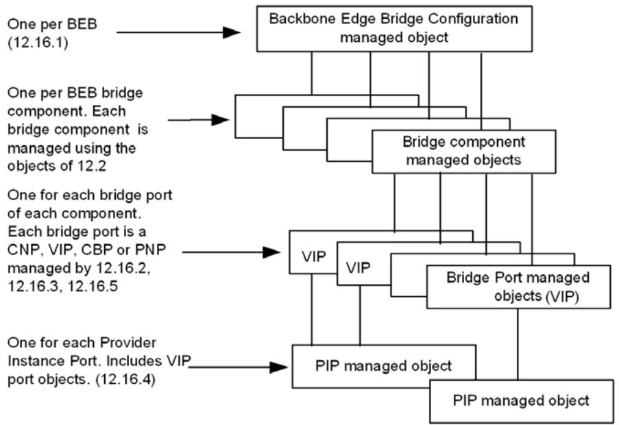
Figure 12-2—Relationship among BEB managed objects
Each VLAN Bridge component relays frames between Bridge Ports. In a BEB, these Bridge Ports can provide external connectivity directly, or can connect to other Bridge components through internal LANs. Each component contained within a BEB is associated with the BEB configuration managed object representing that BEB. The component is uniquely identified within the PBBN by the combination of a componentID unique within the BEB and by the MAC address of the BEB within that the component is contained. Each component may also be identified by the MAC address of the component that is unique within the PBBN. Within a BEB, a B-component uses two types of Bridge Ports—PNPs and CBPs—and an I-component uses two types of Bridge Ports—VIPs and CNPs. Each Bridge Port is represented by a Bridge Port managed object (12.4.2), a Provider Bridge Port Type managed object (12.13.1), and a BEB port configuration managed object (12.16.2). Each such managed object is uniquely identified, within the BEB, by the combination of the ComponentID and Port Number (12.3) of the associated Bridge Port.
Each VIP associated with an I-component is mapped to a PIP associated with that I-component. In general, multiple VIPs are associated with a single PIP. PIPs are not Bridge Ports, though they are ports on BEBs, as they are not used directly by the MAC Relay Entity (see Clause 8) of a Bridge component. Each VIP is supported by one and only one PIP. Each PIP is therefore identified uniquely by the ComponentID and Port Number of any of the VIPs that it supports and by convention is referenced by the smallest Port Number supported by the PIP. Each PIP is managed using the PIP configuration managed object (12.16.4), and each VIP is managed using the VIP configuration managed object of (12.16.3).
PIPs and CBPs of a BEB may be internal or external. Each externally accessible port on a BEB is designated as a PNP, CBP, PIP, or CNP.
The following managed objects define the semantics of the management operations specific to BEBs:
d) The BEB configuration managed object (12.16.1)
e) The BEB/PB/VLAN Bridge Port configuration managed object (12.16.2)
f) The VIP configuration managed object (12.16.3)
g) The PIP configuration managed object (12.16.4)
h) The CBP configuration managed object (12.16.5)
NOTE—All objects specified in 12.16 are persistent over power-up/down and system reboot unless otherwise specified.
12.16.1 BEB configuration managed object
The BEB configuration managed object identifies a BEB and all the managed objects that manage the BEB. The management operations that can be performed on the BEB configuration managed object are as follows:
a) Read BEB configuration (12.16.1.1)
b) Set BEB configuration (12.16.1.2)
c) Create BEB component (12.16.1.3)
d) Delete BEB component (12.16.1.4)
e) Create BEB Bridge Port (12.16.1.5)
f) Create BEB PIP (12.16.1.6)
g) Delete BEB Bridge Port (12.16.1.7)
h) Delete BEB PIP (12.16.1.8)
Items marked “(MIRP only)” shall be supported if the B-component supports the Multiple I-SID Registration Protocol (MIRP) (Clause 39).
12.16.1.1 Read BEB configuration
12.16.1.1.1 Purpose
All BEBs shall implement the read BEB configuration function to obtain information regarding the type of components and ports within a BEB. Items marked “(MIRP only)” shall be supported if the B-component supports the Multiple I-SID Registration Protocol (MIRP) (Clause 39).
12.16.1.1.2 Inputs
None.
12.16.1.1.3 Outputs
a) BEB address—the MAC address for the BEB used to access the BEB configuration managed object (8.13.8). Each BEB has a single BEB address even if the BEB has many components.
b) BEB name—a text string of up to 32 characters, of locally determined significance.
c) Number of I-components—in the BEB, which may range from 0 to many.
d) I-component addresses—a list specifying the following for each I-component or a NULL list value for no I-components:
1) ComponentID—the number of the I-component.
2) A Bridge address that is the MAC address for the I-Component (8.13.8).
e) Number of B-components—in the BEB, which may be 0 or 1.
f) B-component address—a list specifying the following for the B-component or a NULL list value for no B-component.
1) ComponentID—the number of the B-component.
2) A Bridge address that is the MAC address for the B-component (8.13.8).
g) Number of BEB ports (MAC Entities).
h) Port addresses—a list specifying the following for each port:
1) ComponentID—the number identifying the Bridge component associated with this port.
2) An interface—either that component’s Port Number for the Bridge Port, or in the case of a PIP, the PIP Index.
3) Port address—the specific MAC address associated with the port (8.13.2).
4) External port—a Boolean indicating that the port is an external port.
i) (MIRP only) A Boolean value specifying whether MIRP is (TRUE) or is not (FALSE) enabled in this B-component (Clause 39).
j) (MIRP only) The MIRP B-VID to which MIRPDUs transmitted from a PNP are to be assigned if item (k) contains the value cbpMirpGroup (1). The value 0 (the default value) indicates that the CBP PVID is to be used (39.2.1.6).
k) (MIRP only) An enumerated value specifying what destination_address and vlan_identifier are to be used when the MIRP Participant transmits an MIRPDU from a PNP:
1) cbpMirpGroup: Use the Nearest Customer Bridge group address from Table 8-1 with the MIRP B-VID (this is the default value) [item (a) in 39.2.1.6];
2) cbpMirpVlan: Use the Nearest Customer Bridge group address from Table 8-1 with the B-VID field from the Backbone Service Instance table [item (b) in 39.2.1.6]; or
3) cbpMirpTable: Use the Default Backbone Destination and B-VID fields from the Backbone Service Instance table [item (c) in 39.2.1.6].
l) (MIRP only) A Boolean value specifying the administrative status requested by management for attaching a MIRP Participant to a PNP or management Port. If TRUE, the BEB is to attach a MIRP Participant to exactly one PNP or management Port, and if FALSE, no MIRP Participant is to be present on any PNP or management Port. Default value is TRUE (39.1.2).
m) (MIRP only) The read-only Bridge Port Number (or 0, if none) of the PNP to which the MIRP Participant is attached (39.1.2).
12.16.1.2 Set BEB configuration
12.16.1.2.1 Purpose
All BEBs shall implement the set BEB configuration function to set the BEB Name. Items marked “(MIRP only)” shall be supported if the B-component supports the Multiple I-SID Registration Protocol (MIRP) (Clause 39). All items are persistent over power up or reboot.
12.16.1.2.2 Inputs
a) BEB Name—a text string of up to 32 characters, of locally determined significance.
b) (MIRP only) A Boolean value specifying whether MIRP is (TRUE) or is not (FALSE) enabled in this B-component (Clause 39).
c) (MIRP only) The MIRP B-VID to which received MIRPDUs are to be assigned if item (d) contains the value cbpMirpGroup (1). The value 0 (the default) indicates that the CBP PVID is to be used (39.2.1.6).
d) (MIRP only) An enumerated value specifying what destination_address and vlan_identifier are to be used when the MIRP Participant transmits an MIRPDU towards the MAC relay entity, either cbpMirpGroup (1), cbpMirpVlan (2), or cbpMirpTable (3) (39.2.1.6).
e) (MIRP only) A Boolean value specifying the administrative status requested by management for attaching a MIRP Participant to a PNP or management Port. If TRUE, the BEB is to attach a MIRP Participant to exactly one PNP or management Port, and if FALSE, no MIRP Participant is to be present on any PNP or management Port (39.1.2).
12.16.1.2.3 Outputs
None.
12.16.1.3 Create BEB component (optional)
12.16.1.3.1 Purpose
A BEB may implement the create BEB component function to allow the dynamic creation of new components. Components created by this command are persistent over power-up or reboot.
12.16.1.3.2 Inputs
a) ComponentType: this takes one of the following values:
1) I-Comp
2) B-Comp
12.16.1.3.3 Outputs
None.
12.16.1.4 Delete BEB component (optional)
12.16.1.4.1 Purpose
A BEB may implement the delete BEB component function to allow deletion of components. Component deletion using this command is persistent over power-up or reboot.
12.16.1.4.2 Inputs
a) ComponentID—indicates the component being deleted.
12.16.1.4.3 Outputs
None.
12.16.1.5 Create BEB Bridge Port (optional)
12.16.1.5.1 Purpose
A BEB may implement the create BEB Bridge Port function to allow dynamic creation of Bridge Ports. Bridge Ports created by this command are persistent over power-up or reboot.
12.16.1.5.2 Inputs
a) Port Index—indicates the port where the new Bridge Port will be created.
b) ComponentID—indicates the component where the new Bridge Port will be created.
c) Port type—this takes one of the following values:
1) CNP
2) PNP
3) CBP
4) VIP
12.16.1.5.3 Outputs
None.
12.16.1.6 Create BEB PIP (optional)
12.16.1.6.1 Purpose
A BEB may implement the create BEB PIP function to allow dynamic creation of PIPs. PIPs created by this command are persistent over power-up or reboot.
12.16.1.6.2 Inputs
a) Port Index—indicates the port where the new PIP will be created.
b) ComponentID—indicates the component where the new PIP will be created.
12.16.1.6.3 Outputs
None.
12.16.1.7 Delete BEB Bridge Port (optional)
12.16.1.7.1 Purpose
A BEB may implement the delete BEB Bridge Port function to allow deletion of Bridge Ports. Bridge Port deletion using this command is persistent over power-up or reboot.
12.16.1.7.2 Inputs
a) ComponentID—the component for the Bridge Port.
b) Port Number—the Port Number for the Bridge Port.
12.16.1.7.3 Outputs
None.
12.16.1.8 Delete BEB PIP (optional)
12.16.1.8.1 Purpose
A BEB may implement the delete BEB PIP function to allow deletion of PIPs. PIP deletion using this command is persistent over power-up or reboot.
12.16.1.8.2 Inputs
a) PIP Index—identifies the PIP within the BEB.
12.16.1.8.3 Outputs
None.
12.16.2 BEB/PB/VLAN Bridge Port configuration managed object
The management operations that can be performed on the BEB/PB/VLAN Bridge Port configuration managed object are as follows:
a) Read BEB/PB/VLAN Bridge port configuration (12.16.2.1).
12.16.2.1 Read BEB/PB/VLAN Bridge port configuration
12.16.2.1.1 Purpose
All BEBs shall implement the read BEB/PB/VLAN Bridge port configuration function to obtain information regarding the port type of a Bridge Port on the BEB.
12.16.2.1.2 Inputs
a) ComponentID—the number identifying the Bridge component associated with this port.
b) Port Number—that component’s Port Number for the Bridge Port.
12.16.2.1.3 Outputs
a) Port Type—this takes one of the following values:
1) C-VLAN Port
2) PNP (identical to the PNP Bridge Port type specified by 12.13.1)
3) CNP (identical to the CNP Bridge Port type specified by 12.13.1)
4) CEP (identical to the CEP Bridge Port type specified by 12.13.1)
5) CBP (5.12, 6.11, 12.13.1 will indicate PNP)
6) VIP (5.12, 6.10, 12.13.1 will indicate PNP)
NOTE—Support for C-VLAN ports requires equipment with VLAN Bridge (5.9) functions in addition to BEB (5.12) functions. Support for CEP ports requires equipment with Provider Bridge (5.10) functions in addition to BEB functions.
12.16.3 VIP configuration managed object
The VIP configuration managed object applies to each VIP (6.10) on a BEB whether its associated PIP is externally or internally accessible.
It includes
a) The VIP configuration parameters, which provide the subset of the Bridge VLAN Configuration managed object (12.10.1) that is relevant for the configuration of the backbone service instance.
The management operations that can be performed are as follows:
b) Read VIP configuration (12.16.3.1).
c) Set VIP configuration (12.16.3.2).
12.16.3.1 Read VIP configuration
12.16.3.1.1 Purpose
All BEBs with I-components shall implement the read VIP configuration function to allow reading the current configuration of the VIPs (6.10) in an I-component of a BEB. Each VIP is configured by 12.8, 12.10, 12.16.3.2. The adminPointToPointMAC parameter is configured by 12.8.2.3.2 while the PVID and Acceptable Frame Types parameters are supplied by the Bridge Port configuration of 12.10.1.2 and 12.10.1.3.
12.16.3.1.2 Inputs
a) ComponentID—the number identifying the Bridge component associated with this port.
b) Port Number—that component’s Port Number for the Bridge Port.
12.16.3.1.3 Outputs
a) ComponentID—the number identifying the Bridge component associated with this port.
b) Port Number—that component’s Port Number for the Bridge Port.
c) PIP Name—a text string of up to 32 characters that identifies the PIP within a BEB with which this VIP is associated.
d) VIP-ISID—the I-SID associated with this VIP (6.10).
e) Default Backbone Destination—an EUI-48 DA (6.10.2).
g) enableConnectionIdentifier—A Boolean to indicate if the connection_identifier parameter is allowed to learn associations between a B-MAC address and a C-MAC address (6.10).
12.16.3.2 Set VIP configuration
12.16.3.2.1 Purpose
All BEBs with I-components shall implement the set VIP configuration function to allow setting the configuration of the internal VIP in the I-component of a BEB.
12.16.3.2.2 Inputs
a) ComponentID—the number identifying the Bridge component associated with this port.
b) Port Number—that component’s Port Number for the Bridge Port.
c) VIP-ISID—the I-SID associated with this VIP (6.10).
e) enableConnectionIdentifier—A Boolean that determines if the connection_identifier parameter is allowed to learn associations between a B-MAC address and a C-MAC address (6.10). The default value is TRUE. This parameter should be configured to FALSE at the root node of a point-tomultipoint TESI.
12.16.3.2.3 Outputs
a) Operation status. This takes one of the following values:
1) Operation rejected because the Bridge Port identified by the ComponentID and Port Number is not a VIP;
2) Operation accepted.
12.16.4 PIP configuration managed object
The PIP Configuration managed object applies to each PIP (6.10) on a BEB.
It includes the following:
a) The VIP mapping, which provides the set of VIPs multiplexed on this PIP
b) The PIP MAC address, which is used as the B-SA for all encapsulated frames
The management operations that can be performed are as follows:
c) Read PIP Configuration (12.16.4.1)
d) Optionally, Set PIP Configuration (12.16.4.2)
e) Read VIP to PIP mapping (12.16.4.3)
f) Optionally, Set VIP to PIP mapping (12.16.4.4)
g) Read PIP Priority Code Point Selection (12.16.4.5)
h) Set PIP Priority Code Point Selection (12.16.4.6)
i) Read PIP Priority Code Point Decoding Table (12.16.4.7)
j) Optionally, Set PIP Priority Code Point Decoding Table (12.16.4.8)
k) Read PIP Priority Code Point Encoding Table (12.16.4.9)
l) Optionally, Set PIP Priority Code Point Encoding Table (12.16.4.10)
m) Read PIP Use_DEI parameter (12.16.4.11)
n) Optionally, Set PIP Use_DEI parameter (12.16.4.12)
o) Read PIP Require Drop Encoding parameter (12.16.4.13)
p) Optionally, Set PIP Require Drop Encoding parameter (12.16.4.14)
12.16.4.1 Read PIP configuration
12.16.4.1.1 Purpose
All BEBs with I-components shall implement the read PIP configuration function to allow reading the current configuration of the PIP in the I-component of a BEB.
12.16.4.1.2 Inputs
a) PIP Index—an identifier for the PIP within this BEB.
12.16.4.1.3 Outputs
a) PIP B-MAC address—identifies the PIP (6.10.2).
b) PIP Name—a text string of up to 32 characters used to identify a PIP within a BEB.
c) ComponentID—the number identifying the I-component with this PIP.
d) VIP map—a bit array of 4094 bits indicating all the VIPs associated with this port.
12.16.4.2 Set PIP configuration (optional)
12.16.4.2.1 Purpose
All BEBs with I-components may implement the set PIP configuration function to set the current configuration of the PIP in the I-component of a BEB.
12.16.4.2.2 Inputs
a) PIP Index—an identifier for the PIP within this BEB.
b) PIP B-MAC address—the B-MAC address used by this PIP in the B-SA field of transmitted frames.
c) PIP Name—a text string of up to 32 characters used to identify the PIP within a BEB.
d) VIP map—a bit array of 4094 bits indicating all the VIPs associated with this PIP.
12.16.4.2.3 Outputs
a) Operation status. This takes one of the following values:
1) Operation rejected because the PIP Index is invalid.
2) Operation rejected because the VIP map identifies a port that is not a VIP.
3) Operation accepted.
12.16.4.3 Read VIP to PIP mapping
12.16.4.3.1 Purpose
All BEBs with I-components shall implement the read VIP to PIP mapping function to allow reading the VIP to PIP map information from the PIP configuration managed object.
12.16.4.3.2 Inputs
a) ComponentID—the number identifying a Bridge component with a VIP.
b) Port Number—that component's Port Number for this VIP.
12.16.4.3.3 Outputs
a) ComponentID—the number identifying a Bridge component with a VIP.
b) Port Number—that component’s Port Number for this VIP.
c) PIP Index—identifies the PIP supporting this VIP.
d) PIP B-MAC address—the B-MAC address used by this PIP supporting this VIP (6.10.2).
e) PIP Name—a text string of up to 32 characters identifying the PIP supporting this VIP.
12.16.4.4 Set VIP to PIP mapping (optional)
12.16.4.4.1 Purpose
All BEBs with I-components may implement the set VIP to PIP mapping function to allow binding individual VIPs to PIPs. The set VIP to PIP mapping function allows setting map entries for individual VIPs while the set PIP configuration function sets the entire VIP to PIP map.
12.16.4.4.2 Inputs
a) ComponentID—the number identifying a Bridge component with a VIP.
b) Port Number—that component’s Port Number for this VIP.
c) PIP Index—an identifier for this PIP within this component of the BEB.
12.16.4.4.3 Outputs
a) Operation status. This takes one of the following values:
1) Operation rejected because the ComponentID and Port Number do not identify a VIP.
2) Operation rejected because the PIP Index does not identify a PIP within the specified component.
3) Operation accepted.
12.16.4.5 Read PIP Priority Code Point Selection
12.16.4.5.1 Purpose
To read which row of the Priority Code Point Encoding Table and Priority Code Point Decoding Table (6.10.3) is currently selected for use on this PIP.
12.16.4.5.2 Inputs
a) PIP Index—an identifier for this PIP within this component of the BEB.
12.16.4.5.3 Outputs
a) Priority Code Point Selection: this takes one of the following values:
1) 8P0D
2) 7P1D
3) 6P2D
4) 5P3D
12.16.4.6 Set PIP Priority Code Point Selection
12.16.4.6.1 Purpose
To set which row of the Priority Code Point Encoding Table and Priority Code Point Decoding Table (6.10.3) will be selected for use on this PIP.
12.16.4.6.2 Inputs
a) PIP Index—an identifier for this PIP within this component of the BEB.
b) Priority Code Point Selection—this takes one of the following values:
1) 8P0D
2) 7P1D
3) 6P2D
4) 5P3D
12.16.4.6.3 Outputs
None.
12.16.4.7 Read PIP Priority Code Point Decoding Table
12.16.4.7.1 Purpose
To read the current contents of a row in the Priority Code Point Decoding Table (6.10.3) for a PIP.
12.16.4.7.2 Inputs
a) PIP Index—an identifier for this PIP.
b) Priority Code Point Row—this takes one of the following values:
1) 8P0D
2) 7P1D
3) 6P2D
4) 5P3D
12.16.4.7.3 Outputs
a) Priority value for Priority Code Point 0: Integer in range 0–7.
b) Drop_eligible value for Priority Code Point 0: Boolean.
c) Priority value for Priority Code Point 1: Integer in range 0–7.
d) Drop_eligible value for Priority Code Point 1: Boolean.
e) Priority value for Priority Code Point 2: Integer in range 0–7.
f) Drop_eligible value for Priority Code Point 2: Boolean.
g) Priority value for Priority Code Point 3: Integer in range 0–7.
h) Drop_eligible value for Priority Code Point 3: Boolean.
i) Priority value for Priority Code Point 4: Integer in range 0–7.
j) Drop_eligible value for Priority Code Point 4: Boolean.
k) Priority value for Priority Code Point 5: Integer in range 0–7.
l) Drop_eligible value for Priority Code Point 5: Boolean.
m) Priority value for Priority Code Point 6: Integer in range 0–7.
n) Drop_eligible value for Priority Code Point 6: Boolean.
o) Priority value for Priority Code Point 7: Integer in range 0–7.
p) Drop_eligible value for Priority Code Point 7: Boolean.
12.16.4.8 Set PIP Priority Code Point Decoding Table (optional)
12.16.4.8.1 Purpose
To modify the contents of a row in the Priority Code Point Decoding Table (6.10.3) for a PIP.
12.16.4.8.2 Inputs
a) PIP Index—an identifier for this PIP.
b) b) Priority Code Point Row—this takes one of the following values:
1) 8P0D
2) 7P1D
3) 6P2D
4) 5P3D
c) Priority value for Priority Code Point 0: Integer in range 0–7.
d) Drop_eligible value for Priority Code Point 0: Boolean.
e) Priority value for Priority Code Point 1: Integer in range 0–7.
f) Drop_eligible value for Priority Code Point 1: Boolean.
g) Priority value for Priority Code Point 2: Integer in range 0–7.
h) Drop_eligible value for Priority Code Point 2: Boolean.
i) Priority value for Priority Code Point 3: Integer in range 0–7.
j) Drop_eligible value for Priority Code Point 3: Boolean.
k) Priority value for Priority Code Point 4: Integer in range 0–7.
l) Drop_eligible value for Priority Code Point 4: Boolean.
m) Priority value for Priority Code Point 5: Integer in range 0–7.
n) Drop_eligible value for Priority Code Point 5: Boolean.
o) Priority value for Priority Code Point 6: Integer in range 0–7.
p) Drop_eligible value for Priority Code Point 6: Boolean.
q) Priority value for Priority Code Point 7: Integer in range 0–7.
r) Drop_eligible value for Priority Code Point 7: Boolean.
12.16.4.8.3 Outputs
None.
12.16.4.9 Read PIP Priority Code Point Encoding Table
12.16.4.9.1 Purpose
To read the current contents of a row in the Priority Code Point Encoding Table (6.10.3) for a Port.
12.16.4.9.2 Inputs
a) PIP Index—an identifier for this PIP.
b) Priority Code Point Row: this takes one of the following values:
1) 8P0D
2) 7P1D
3) 6P2D
4) 5P3D
12.16.4.9.3 Outputs
a) Priority Code Point value for priority 0 with drop_eligible False: Integer in range 0–7.
b) Priority Code Point value for priority 0 with drop_eligible True: Integer in range 0–7.
c) Priority Code Point value for priority 1 with drop_eligible False: Integer in range 0–7.
d) Priority Code Point value for priority 1 with drop_eligible True: Integer in range 0–7.
e) Priority Code Point value for priority 2 with drop_eligible False: Integer in range 0–7.
f) Priority Code Point value for priority 2 with drop_eligible True: Integer in range 0–7.
g) Priority Code Point value for priority 3 with drop_eligible False: Integer in range 0–7.
h) Priority Code Point value for priority 3 with drop_eligible True: Integer in range 0–7.
i) Priority Code Point value for priority 4 with drop_eligible False: Integer in range 0–7.
j) Priority Code Point value for priority 4 with drop_eligible True: Integer in range 0–7.
k) Priority Code Point value for priority 5 with drop_eligible False: Integer in range 0–7.
l) Priority Code Point value for priority 5 with drop_eligible True: Integer in range 0–7.
m) Priority Code Point value for priority 6 with drop_eligible False: Integer in range 0–7.
n) Priority Code Point value for priority 6 with drop_eligible True: Integer in range 0–7.
o) Priority Code Point value for priority 7 with drop_eligible False: Integer in range 0–7.
p) Priority Code Point value for priority 7 with drop_eligible True: Integer in range 0–7.
12.16.4.10 Set PIP Priority Code Point Encoding Table (optional)
12.16.4.10.1 Purpose
To modify the contents of a row in the Priority Code Point Encoding Table (6.10.3) for a PIP.
12.16.4.10.2 Inputs
a) PIP Index—an identifier for this PIP.
b) b) Priority Code Point Row—this takes one of the following values:
1) 8P0D
2) 7P1D
3) 6P2D
4) 5P3D
c) Priority Code Point value for priority 0 with drop_eligible False: Integer in range 0–7.
d) Priority Code Point value for priority 0 with drop_eligible True: Integer in range 0–7.
e) Priority Code Point value for priority 1 with drop_eligible False: Integer in range 0–7.
f) Priority Code Point value for priority 1 with drop_eligible True: Integer in range 0–7.
g) Priority Code Point value for priority 2 with drop_eligible False: Integer in range 0–7.
h) Priority Code Point value for priority 2 with drop_eligible True: Integer in range 0–7.
i) Priority Code Point value for priority 3 with drop_eligible False: Integer in range 0–7.
j) Priority Code Point value for priority 3 with drop_eligible True: Integer in range 0–7.
k) Priority Code Point value for priority 4 with drop_eligible False: Integer in range 0–7.
l) Priority Code Point value for priority 4 with drop_eligible True: Integer in range 0–7.
m) Priority Code Point value for priority 5 with drop_eligible False: Integer in range 0–7.
n) Priority Code Point value for priority 5 with drop_eligible True: Integer in range 0–7.
o) Priority Code Point value for priority 6 with drop_eligible False: Integer in range 0–7.
p) Priority Code Point value for priority 6 with drop_eligible True: Integer in range 0–7.
q) Priority Code Point value for priority 7 with drop_eligible False: Integer in range 0–7.
r) Priority Code Point value for priority 7 with drop_eligible True: Integer in range 0–7.
12.16.4.10.3 Outputs
None.
12.16.4.11 Read PIP Use_DEI parameter
12.16.4.11.1 Purpose
To read the current state of the Use_DEI parameter (6.10.3) for the PIP.
12.16.4.11.2 Inputs
a) PIP Index—an identifier for this PIP.
12.16.4.11.3 Outputs
a) Use_DEI parameter: Boolean.
12.16.4.12 Set PIP Use_DEI parameter (optional)
12.16.4.12.1 Purpose
To set the current state of the Use_DEI parameter (6.10.3) for the PIP.
12.16.4.12.2 Inputs
a) PIP Index—an identifier for this PIP.
b) Use_DEI parameter: Boolean.
12.16.4.12.3 Outputs
None.
12.16.4.13 Read PIP Require Drop Encoding parameter
12.16.4.13.1 Purpose
To read the current state of the Require Drop Encoding parameter (8.6.6) for the PIP.
12.16.4.13.2 Inputs
a) PIP Index—an identifier for this PIP.
12.16.4.13.3 Outputs
a) Require Drop Encoding parameter—Boolean.
12.16.4.14 Set PIP Require Drop Encoding parameter (optional)
12.16.4.14.1 Purpose
To set the current state of the Require Drop Encoding parameter (8.6.6) for the PIP.
12.16.4.14.2 Inputs
a) PIP Index—an identifier for this PIP.
b) Require Drop Encoding parameter—Boolean.
12.16.4.14.3 Outputs
None.
12.16.5 CBP Configuration managed object
The CBP Configuration managed object includes the following:
a) A Backbone Service Instance table (6.11)
b) A Flow Filtering Control Table (44.2.2)
Item b) is applicable only on BEBs supporting ECMP with flow filtering.
The management operations that can be performed are as follows:
c) Read Backbone Service Instance table entry (12.16.5.1)
d) Set Backbone Service Instance table entry (12.16.5.2)
e) TESI assignment managed object (12.16.5.3)
f) Read Flow Filtering Control Table entry (12.16.5.4)
g) Set Flow Filtering Control Table entry (12.16.5.5)
12.16.5.1 Read Backbone Service Instance table entry
12.16.5.1.1 Purpose
All BEBs shall implement the read Backbone Service Instance table entry function to allow reading the Backbone Service Instance table entries in the CBP configuration managed object.
12.16.5.1.2 Inputs
a) ComponentID—the number identifying the Bridge component associated with this port.
b) Port Number —that component’s Port Number for the Bridge Port.
c) Backbone-SID —identifying the backbone service instance (6.11).
12.16.5.1.3 Outputs
a) ComponentID—the number identifying the Bridge component associated with this port.
b) Port Number—that component’s Port Number for the Bridge Port.
c) Backbone-SID—the identifier used in the PBBN for the backbone service instance (6.11).
d) B-VID (optional)—12-bit VID (6.11).
e) Default Backbone Destination (optional)—EUI-48 DA (6.11).
f) Local-SID (optional)—24-bit I-SID value (6.11).
12.16.5.2 Set Backbone Service Instance table entry
12.16.5.2.1 Purpose
All BEBs shall implement the set Backbone Service Instance table entry function to allow configuration of the backbone service instances available on each CBP. This information is persistent over power-up or reboot.
12.16.5.2.2 Inputs
a) ComponentID—the number identifying the Bridge component associated with this port.
b) Port Number—that component’s Port Number for the Bridge Port.
c) Backbone-SID—24-bit I-SID value (6.11).
d) B-VID (optional)—12-bit VID (6.11).
e) Default Backbone Destination (optional)—EUI-48 DA (6.11).
f) Local-SID (optional)—24-bit I-SID value (6.11).
12.16.5.2.3 Outputs
a) Operation status—this takes one of the following values:
1) Operation rejected because the ComponentID and Port Number do not identify a valid CBP.
2) Operation rejected because the B-VID is assigned to ECMP with flow filtering (12.25.4.1, Table 44-1) and the Bridge does not support flow filtering.
3) Operation accepted.
12.16.5.3 TESI assignment managed object
12.16.5.3.1 Purpose
All CBPs providing TESIs shall implement the TESI assignment managed object to assign a particular TESI on this CBP.
12.16.5.3.2 Inputs
a) ComponentID—the number identifying the Bridge component associated with this port.
b) Port Number—that component’s Port Number for the Bridge Port.
c) A series of ordered 3-tuples of the form <ESP-DA, ESP-SA, ESP-VID>.
12.16.5.3.3 Outputs
a) Operation status—this takes one of the following values:
1) Operation rejected because the ComponentID and Port Number do not identify a valid CBP;
2) Operation rejected because a 3-tuple in the provided series has a VID value in its ESP-VID field that is not allocated to TE-MSTID;
3) Operation rejected because no 3-tuple in the provided series has the CBP’s MAC address in its ESP-SA field;
4) Operation rejected because there are only two 3-tuples provided and the values in their ESP-DA and ESP-SA fields are not reversed;
5) Operation rejected because there are more than two different values specified in the ESP-DA fields of the provided series of 3-tuples;
6) Operation accepted.
12.16.5.4 Read Flow Filtering Control Table entry
12.16.5.4.1 Purpose
BEBs supporting ECMP with flow filtering shall implement the read Flow Filtering Control Table entry function to allow reading the Flow Filtering Control Table entries in the CBP configuration managed object.
12.16.5.4.2 Inputs
a) ComponentID—the number identifying the bridge component associated with this port.
b) Port Number —that component’s Port Number for the Bridge Port.
c) VID —identifying a B-VID.
12.16.5.4.3 Outputs
a) Operation status—this takes one of the following values:
1) Operation rejected because the ComponentID and Port Number do not identify a valid CBP;
2) Operation rejected because the CBP does not support F-TAG processing;
3) Operation accepted.
b) ComponentID—the number identifying the bridge component associated with this port.
c) Port Number—that component’s Port Number for the Bridge Port.
d) VID—the identifier of a B-VLAN.
e) Flow Filtering—indicates whether flow filtering behavior is enabled on the port for the VID (enabled/disabled).
f) Flow Hash Generation—indicates whether flow hash generation is enabled on the port for the VID (enabled/disabled).
g) TTL Value—the initial TTL value for frames entering the flow filtering SPT Domain (1..63).
12.16.5.5 Set Flow Filtering Control Table entry
12.16.5.5.1 Purpose
BEBs supporting ECMP with flow filtering shall implement the set Flow Filtering Control Table entry function to allow configuration of the initial TTL value for frames entering an SPT Domain. This information is persistent over power-up or reboot.
12.16.5.5.2 Inputs
a) ComponentID—the number identifying the bridge component associated with this port.
b) Port Number—that component’s Port Number for the Bridge Port.
c) VID—12-bit VID.
d) TTL Value—the initial TTL value for frames entering the SPT Domain, Integer in range 1–63. The default value is 8.
NOTE—The Flow Filtering and Flow Hash Generation fields in the Flow Filtering Control Table are controlled by ISIS-SPB (28.8) and therefore are not settable by management.
12.16.5.5.3 Outputs
a) Operation status—this takes one of the following values:
1) Operation rejected because the ComponentID and Port Number do not identify a valid CBP;
2) Operation rejected because the CBP does not support F-TAG processing;
3) Operation accepted.
12.17 DDCFM entities
The following are the DDCFM managed objects in a Bridge:
a) DDCFM Stack managed object (12.17.1)
b) Reflection Responder managed object (12.17.2)
c) RFM Receiver managed object (12.17.3)
d) Decapsulator Responder managed object (12.17.4)
e) SFM Originator managed object (12.17.5)
12.17.1 DDCFM Stack managed object
There is one DDCFM Stack managed object per Bridge. It allows the network administrator to retrieve DDCFM entities configured on a particular Bridge Port or an aggregated port within a Bridge Port. The management operation that can be performed is
a) Read DDCFM Stack managed object (12.17.1.1)
12.17.1.1 Read DDCFM Stack managed object
12.17.1.1.1 Purpose
To retrieve DDCFM entities configured on a particular Bridge Port or an aggregated port within a Bridge Port.
12.17.1.1.2 Input
a) An interface, either a Bridge Port, or an aggregated port within a Bridge Port
12.17.1.1.3 Outputs
a) Operation status. This takes one of the following values:
1) Operation rejected because of invalid reference to an interface;
2) Operation accepted, but there is no DDCFM entity configured on the specified interface; or
3) Operation accepted, there are (is a) DDCFM entities (entity) configured on the specified interface, and
b) If there are DDCFM entities configured on the specified interface, the following attributes should be returned:
1) An RR is configured, its associated maintenance domain, and the value indicating its direction; and/or
2) An RFM Receiver is configured, its associated maintenance domain; and/or
3) A DR is configured, its associated maintenance domain, and its associated MA; and/or
4) An SFM Originator is configured, its associated maintenance domain, its associated MA, and the value indicating its direction.
12.17.2 Reflection Responder managed object
The management operations that can be performed on the Reflection Responder managed object are as follows:
a) Create Reflection Responder managed object (12.17.2.1)
b) Write Reflection Responder managed object’s attributes (12.17.2.2)
c) Read Reflection Responder managed object’s attributes (12.17.2.3)
d) Delete Reflection Responder managed object (12.17.2.4)
e) Activate Reflection Responder (12.17.2.5)
f) Deactivate Reflection Responder (12.17.2.6)
12.17.2.1 Create Reflection Responder managed object
12.17.2.1.1 Purpose
To create a Reflection Responder (RR). After the creation, all the writable attributes have their default values unless being configured differently by the Write Reflection Responder managed object operation (12.17.2.2). The RR is in the inactive state after the creation and remains so until activated by a subsequent Activate Reflection Responder operation (12.17.2.5).
12.17.2.1.2 Inputs
a) A reference to a particular Reflection Responder managed object, which includes the following:
1) An interface (either a Bridge Port or an aggregated port within a Bridge Port) on which the RR is defined. The interface identifier could be MAC address or port identifier.
2) A reference to a particular Maintenance Domain managed object (12.14.5).
3) A value indicating the direction in which the RR faces, which can be either Down [Active SAP is further away from the Frame filtering entity (default)], or Up (Active SAP is closer to the Frame filtering entity).
12.17.2.1.3 Outputs
a) Operation status. This takes one of the following values:
1) Operation rejected because of invalid interface reference or invalid Maintenance Domain level; or
2) Operation accepted.
12.17.2.2 Write Reflection Responder managed object’s attributes
12.17.2.2.1 Purpose
To configure and alter the value of one or more writable attribute(s) of an Reflection Responder managed object. The attributes of an Reflection Responder managed object cannot be modified when the RR is active.
12.17.2.2.2 Inputs
a) Reference to a Reflection Responder managed object [12.17.2.1.2, item a)].
b) Writable attributes are as follows:
1) Reference to a Maintenance Association managed object (12.14.6) within the RR’s Maintenance Domain. If set to 0, the MA associated with the filtered frame shall be used for the Reflected Frame Message (RFM) emitted by the RR.
2) Reflection Filter definition(s), which is to specify what data frames are selected to be reflected. Multiple filters can be combined together by “&& (and)”, “|| (or)”, or “! (negation)” operations with precedence association being determined by “( ).” DDCFM-capable Bridges shall support each of the following filter primitives. Implementers may support additional filters, such as length of data frame being equal, larger or smaller than a particular value.
— All;
VID== vid; This primitive uses SVID if the RR is defined on a S component, and CVID if the RR is defined on a C component. Untagged frame shall not be selected by this filter primitive;
DA == xx.xx.xx.xx.xx.xx;
SA == xx.xx.xx.xx.xx.xx;
The first 2 bytes of the EtherType field ==xx;
3) Sampling Interval (29.2.3.4).
4) Reflection Target Address, which is a MAC address to which the reflected frames are targeted. Only individual address is allowed for the Reflection Target Address. The default is the source_address of the selected data frame being used for Reflection Target Address.
5) Continue option, indicating whether the selected data frames are to be continued toward the destination_address specified in the data frame. The default is TRUE to allow data frames to be forwarded to their destinations.
6) Boolean variable indicating if the duration is in seconds or in number of data frames.
7) Duration in seconds for the RR to remain active after being activated. Minimum 1 and maximum is implementation dependent.
8) The number data frames for the RR to reflect after being activated. Once this frame count is reached, the RR shall be deactivated automatically. Default is 0, which means the duration is limited by RR’s timer.
The priority and drop_eligible parameters to be used in the transmitted encapsulated frames (default value: the highest priority, i.e., that with the highest numerical value, allowed to pass through the Bridge Port for any of the VID. Default value for drop_eligible is FALSE).
10) FloodingEnabled Flag indicating whether flooding is allowed if Egress port cannot be identified for RFM by the FDB.
11) Truncation flag indicating if the received data frame should be truncated to keep the length of RFM encapsulated frame not exceeding the Maximum Service Data Unit Size (6.5.8). If the Truncation flag is not set and the RFM encapsulated frame exceeds the Maximum Service Data Unit Size, the filtered data frame is fragmented to two smaller frames and encapsulated in two separate RFMs.
12.17.2.2.3 Outputs
a) Operation status. This takes one of the following values:
1) Operation rejected because the referenced Reflection Responder managed object does not exist;
2) Operation rejected because of one or more invalid writable attribute(s);
3) Operation rejected because the referenced RR is active; or
4) Operation accepted.
12.17.2.3 Read Reflection Responder managed object’s attributes
12.17.2.3.1 Purpose
To retrieve values of attributes in a Reflection Responder managed object.
12.17.2.3.2 Input
a) Reference to a particular Reflection Responder managed object [12.17.2.1.2 item a)]
12.17.2.3.3 Outputs
a) Operation status. This takes one of the following values:
1) Operation rejected because of invalid reference to the Reflection Responder managed object;
2) Operation rejected because there is no RR with the given reference; or
3) Operation accepted.
b) If the operation is accepted, the following attributes for the RR should be returned:
1) Reference to the Reflection Responder managed object;
2) Reference to a Maintenance Association managed object (12.14.6) for the RFMs generated by the RR (writable);
3) Reflection Filter definition(s) (writable);
4) Sampling Interval (writable);
5) The Reflection Target Address (writable);
6) Continue option (writable);
7) Duration for RR to stay active after being activated (writable);
8) DurationInTimeFlag (writable);
9) The priority and drop_eligible parameters to be used in the transmitted RFMs (writable);
10) FloodingFlag (writable);
11) Truncation flag (writable);
12) Activation status (TRUE or FALSE);
13) Remaining time or count left for the RR to be active; and
14) nextRFMtransID (29.3.1.16) value.
12.17.2.4 Delete Reflection Responder managed object
12.17.2.4.1 Purpose
To delete a Reflection Responder managed object. If the corresponding RR is still active, the deletion will deactivate the RR and then delete the corresponding managed object.
12.17.2.4.2 Input
a) Reference to a Reflection Responder managed object [12.17.2.1.2, item a)]
12.17.2.4.3 Outputs
a) Operation status: this takes one of the following values:
1) Operation rejected because of invalid reference to RR;
2) Operation rejected because the referenced RR managed does not exist; or
3) Operation accepted.
12.17.2.5 Activate Reflection Responder
12.17.2.5.1 Purpose
To activate an RR.
Depending on the filter conditions specified for each RR, some RRs can potentially reflect large amount of data frames into the network, which could cause excessive extra traffic injected into the network and impact network performance. For those RRs, it is recommended that no more than one instance of the Reflection Responder managed object be activated per MD for an RR associated with an MP and that no more than one instance of the Reflection Responder managed object be activated per VID for an RR not associated with an MP (e.g., for an RR created on a Bridge Port).
12.17.2.5.2 Inputs
a) Reference to a Reflection Responder managed object [12.17.2.1.2 a)].
12.17.2.5.3 Outputs
a) Operation status. This takes one of the following values:
1) Operation rejected because invalid reference or the referenced RR does not exist;
2) Operation rejected because of the referenced RR already being activated; or
3) Operation accepted.
12.17.2.6 Deactivate Reflection Responder
12.17.2.6.1 Purpose
To deactivate an active RR before its duration expires.
12.17.2.6.2 Input
a) Reference to a Reflection Responder managed object [12.17.2.1.2, item a)].
12.17.2.6.3 Outputs
a) Operation status. This takes one of the following values:
1) Operation rejected because invalid reference or the referenced RR does not exist;
2) Operation rejected because of the referenced RR not being activated; or
3) Operation accepted.
12.17.3 RFM Receiver managed object
The management operations that can be performed on the RFM Receiver managed object are as follows:
a) Create RFM Receiver managed object (12.17.3.1)
b) Delete RFM Receiver managed object (12.17.3.2)
An RFM Receiver is active when the corresponding RFM Receiver managed object is created. Therefore, there is no “Activate and Deactivate” operations for the RFM Receiver managed object.
12.17.3.1 Create RFM Receiver managed object
12.17.3.1.1 Purpose
To create an RFM Receiver managed object. Once an RFM Receiver managed object is created, the corresponding RFM Receiver is able to receive RFMs.
12.17.3.1.2 Inputs
a) Reference to an RFM Receiver managed object, which could be either
1) Reference to an MP; or
2) An interface (either a Bridge Port or an aggregated port within a Bridge Port) on which RFM Receiver is created and a reference to the corresponding RR’s Maintenance Domain managed object.
12.17.3.1.3 Outputs
a) Operation status. This takes one of the following values:
1) Operation rejected because of invalid reference to the RFM Receiver managed object;
2) Operation rejected because the referenced RFM Receiver managed object already exists; or
3) Operation accepted.
12.17.3.2 Delete RFM Receiver managed object
12.17.3.2.1 Purpose
To delete an RFM Receiver managed object.
12.17.3.2.2 Input
a) Reference to an RFM Receiver managed object [12.17.3.1.2, item a)]
12.17.3.2.3 Outputs
a) Operation status. This takes one of the following values:
1) Operation rejected because of invalid reference to the RFM Receiver managed object;
2) Operation rejected because the referenced RFM Receiver managed object does not exist; or
3) Operation accepted.
12.17.4 Decapsulator Responder managed object
The management operations that can be performed on the Decapsulator Responder managed object are as follows:
a) Create Decapsulator Responder managed object (12.17.4.1)
b) Read Decapsulator Responder managed object (12.17.4.2)
c) Write Decapsulator Responder managed object’s attributes (12.17.4.3)
d) Delete Decapsulator Responder managed object (12.17.4.4)
e) Activate Decapsulator Responder (12.17.4.5)
f) Deactivate Decapsulator Responder (12.17.4.6)
12.17.4.1 Create Decapsulator Responder managed object
12.17.4.1.1 Purpose
To create a Decapsulator Responder managed object and corresponding Decapsulator Responder (DR).
12.17.4.1.2 Inputs
a) Reference to a DR, which could be either
1) Reference to an MP; or
2) A triple consisting of an interface (either a Bridge Port or an aggregated port within a Bridge Port), a reference to a Maintenance Domain managed object, and a reference to a Maintenance Association managed object.
12.17.4.1.3 Outputs
a) Operation status. This takes one of the following values:
1) Operation rejected because of invalid reference to a Decapsulator Responder managed object;
2) Operation rejected because the referenced Decapsulator Responder managed object already exists; or
3) Operation accepted.
12.17.4.2 Read Decapsulator Responder managed object
12.17.4.2.1 Purpose
To retrieve the attributes of a Decapsulator Responder managed object.
12.17.4.2.2 Input
a) Reference to a Decapsulator Responder managed object [12.17.4.1.2, item a)].
12.17.4.2.3 Outputs
a) Operation status. This takes one of the following values:
1) Operation rejected because of invalid reference to a Decapsulator Responder managed object;
2) Operation rejected because the referenced Decapsulator Responder managed object does not exist; or
3) Operation accepted.
b) If the operation is accepted, the following attributes for the DR should be returned:
1) Reference to the Decapsulator Responder managed object;
2) MAC address of the SFM Originator (writable);
3) The value of SourceAddressStayFlag (writable);
4) The value of FloodingEnabled flag (writable);
5) The specified duration in seconds, for DR to remain active once activated (writable);
6) Activation status;
7) Remaining time left for DR to be active; and
8) The total number of out-of-sequence SFMs received (29.3.8.7).
12.17.4.3 Write Decapsulator Responder managed object’s attributes
12.17.4.3.1 Purpose
To alter the value of one or more attributes of a Decapsulator Responder managed object when the corresponding DR is not active.
12.17.4.3.2 Inputs
a) Reference to a Decapsulator Responder managed object [12.17.4.1.2, item a)];
b) Reference to the attribute whose value is to be changed;
1) Boolean flag, SourceAddressStayFlag, to enforce the DR not to replace the source_address field of the decapsulated frame with the DR’s own MAC address. Default is FALSE;
2) MAC address of the SFM Originator, which is optional;
3) Boolean FloodingEnabled flag indicating if flooding is allowed (TRUE) or not (FALSE) if the Egress port cannot be identified by the FDB; and
4) Duration in seconds, for DR to remain active once activated.
12.17.4.3.3 Outputs
a) Operation status. This takes one of the following values:
1) Operation rejected because of invalid reference to a Decapsulator Responder managed object;
2) Operation rejected because the referenced Decapsulator Responder managed object does not exist;
3) Operation rejected because of invalid attribute reference or invalid value;
4) Operation rejected because the referenced DR is active; or
5) Operation accepted.
12.17.4.4 Delete Decapsulator Responder managed object
12.17.4.4.1 Purpose
To delete a Decapsulator Responder managed object. If the DR is still active, the deletion will deactivate the DR first and then delete the corresponding managed object.
12.17.4.4.2 Input
a) Reference to a Decapsulator Responder managed object [12.17.4.1.2, item a)].
12.17.4.4.3 Outputs
a) Operation status: this takes one of the following values:
1) Operation rejected because of invalid reference to a Decapsulator Responder managed object;
2) Operation rejected because the referenced Decapsulator Responder managed object does not exist; or
3) Operation accepted.
12.17.4.5 Activate Decapsulator Responder
12.17.4.5.1 Purpose
To activate a DR.
12.17.4.5.2 Input
a) Reference to the Decapsulator Responder managed object [12.17.4.1.2, item a)].
12.17.4.5.3 Outputs
a) Operation status. This takes one of the following values:
1) Operation rejected because of invalid reference;
2) Operation rejected because the referenced Decapsulator Responder managed object does not exist;
3) Operation rejected because the referenced DR has already been activated; or
4) Operation accepted.
12.17.4.6 Deactivate Decapsulator Responder
12.17.4.6.1 Purpose
To deactivate a DR.
12.17.4.6.2 Input
a) Reference to the Decapsulator Responder managed object [12.17.4.1.2, item a)].
12.17.4.6.3 Outputs
a) Operation status. This takes one of the following values:
1) Operation rejected because of invalid reference;
2) Operation rejected because the referenced Decapsulator Responder managed object does not exist;
3) Operation rejected because the referenced DR is not active; or
4) Operation accepted.
12.17.5 SFM Originator managed object
The management operations that can be performed on the SFM Originator managed object are as follows:
a) Create SFM Originator managed object (12.17.5.1)
b) Read SFM Originator managed object (12.17.5.2)
c) Delete SFM Originator managed object (12.17.5.3)
d) Write SFM Originator managed object’s attributes (12.17.5.4)
e) Activate SFM Originator (12.17.5.5)
f) Deactivate SFM Originator (12.17.5.6)
12.17.5.1 Create SFM Originator managed object
12.17.5.1.1 Purpose
To create a SFM Originator managed object.
12.17.5.1.2 Inputs
a) Reference to a SFM Originator managed object, which could be either
1) Reference to an MP; or
2) An interface (either a Bridge Port, or an aggregated port within a Bridge Port), a reference to a Maintenance Domain managed object, a reference to a Maintenance Association managed object, and a value indicating the direction in which the SFM Originator faces on the interface.
12.17.5.1.3 Outputs
a) Operation status. This takes one of the following values:
1) Operation rejected because of invalid reference;
2) Operation rejected because the referenced SFM Originator managed object already exists; or
3) Operation accepted.
12.17.5.2 Read SFM Originator managed object
12.17.5.2.1 Purpose
To retrieve attributes of SFM Originator managed object.
12.17.5.2.2 Inputs
a) Reference to a SFM Originator managed object [12.17.5.1.2, item a)].
12.17.5.2.3 Outputs
a) Operation status. This takes one of the following values:
1) Operation rejected because of invalid reference;
2) Operation rejected because the referenced SFM Originator managed object does not exist; or
3) Operation accepted.
b) If the operation is accepted, following attributes for the SFM Originator should be returned:
1) MAC address of the SFM Originator;
2) MAC address of the corresponding DR (writable);
3) Duration (writable);
4) Activation status: TRUE/FALSE; and
5) The remaining time left for the SFM Originator to remain active.
12.17.5.3 Delete SFM Originator managed object
12.17.5.3.1 Purpose
To delete a SFM Originator managed object, and the corresponding SFM Originator.
12.17.5.3.2 Inputs
a) The reference to a SFM Originator managed object [12.17.5.1.2, item a)].
12.17.5.3.3 Outputs
a) Operation status. This takes one of the following values:
1) Operation rejected because of invalid reference;
2) Operation rejected because the referenced SFM Originator managed object does not exist; or
3) Operation accepted.
12.17.5.4 Write SFM Originator managed object’s attribute
12.17.5.4.1 Purpose
To change an attribute of a SFM Originator managed object.
12.17.5.4.2 Inputs
a) Reference to a SFM Originator managed object [12.17.5.1.2, item a)];
b) MAC address of the corresponding DR; and
c) Duration in seconds, for SFM Originator to stay active once activated.
12.17.5.4.3 Outputs
a) Operation status. This takes one of the following values:
1) Operation rejected because of invalid reference of SFM Originator managed object or the attributes;
2) Operation rejected because the referenced SFM Originator managed object does not exist; or
3) Operation accepted.
12.17.5.5 Activate SFM Originator
12.17.5.5.1 Purpose
To activate a SFM Originator.
12.17.5.5.2 Input
a) Reference to the SFM Originator managed object [12.17.5.1.2, item a)].
12.17.5.5.3 Outputs
a) Operation status. This takes one of the following values:
1) Operation rejected because of invalid reference;
2) Operation rejected because the referenced SFM Originator managed object does not exist;
3) Operation rejected because the referenced SFM Originator has already been activated; or
4) Operation accepted.
12.17.5.6 Deactivate SFM Originator
12.17.5.6.1 Purpose
To deactivate a SFM Originator.
12.17.5.6.2 Input
a) Reference to a SFM Originator managed object [12.17.5.1.2, item a)].
12.17.5.6.3 Output
a) Operation status. This takes one of the following values:
1) Operation rejected because of invalid reference;
2) Operation rejected because the referenced SFM Originator managed object does not exist;
3) Operation rejected because the referenced SFM Originator is not active; or
4) Operation accepted.
12.18 PBB-TE Protection Switching managed objects
The PBB-TE Protection Switching managed objects model operations that create, modify, delete, or inquire about, the configuration and the operation of protection switching. The following are the PBB-TE Protection Switching managed objects in a B-component of an IB-BEB capable of supporting TESIs:
a) The TE protection group list managed object (12.18.1)
b) The TE protection group managed object (12.18.2)
12.18.1 TE protection group list managed object
There is one TE protection group list managed object per IB-BEB. It contains a list of the TE protection groups that have been configured on the IB-BEB.
The management operations that can be performed on the TE protection group list managed object are as follows:
a) Read TE protection group list (12.18.1.1)
b) Create TE protection group managed object (12.18.1.2)
c) Delete TE protection group managed object (12.18.1.3)
12.18.1.1 Read TE protection group list
12.18.1.1.1 Purpose
To obtain information about all of the TE protection groups in an IB-BEB.
12.18.1.1.2 Inputs
None.
12.18.1.1.3 Outputs
A list, perhaps empty, of the TE protection group managed objects configured on the IB-BEB. For each item in the list, the Read TE protection group list command returns:
a) A reference to a particular Maintenance Association managed object (12.14.6) identifying a PBB-TE MA that corresponds to the group’s working entity.
b) A reference to a particular Maintenance Association managed object (12.14.6) identifying a PBB-TE MA with the same endpoints as the one provided in item b) that corresponds to the group’s protection entity.
c) A reference to all TE protection group managed objects (12.18.2) that share a working or protection entity with the TE protection group in the list.
12.18.1.2 Create TE protection group managed object
12.18.1.2.1 Purpose
To create a new TE protection group managed object in an IB-BEB and add it to the IB-BEB’s TE protection group list managed object.
12.18.1.2.2 Inputs
a) A reference to a particular Maintenance Association managed object (12.14.6) identifying a PBB-TE MA that corresponds to the working entity.
b) A reference to a particular Maintenance Association managed object (12.14.6) identifying a PBB-TE MA with the same endpoints as the one provided in item a) that will monitor the protection entity.
12.18.1.2.3 Outputs
a) Operation status. This takes one of the following values:
1) Operation rejected due to nonexistent Maintenance Domain;
2) Operation rejected due to nonexistent MAs;
3) Operation rejected because the referred MAs do not correspond to PBB-TE services;
4) Operation rejected because the two referred MAs do not have the same endpoints;
5) Operation rejected because the two referred MAs do not belong to the same MD;
6) Operation rejected due to duplicate MAs; or
7) Operation accepted. In addition, the list, perhaps empty, of the TE protection group managed objects (12.18.2) that share a working or protection entity with the created TE protection group is provided.
12.18.1.3 Delete TE protection group managed object
12.18.1.3.1 Purpose
To delete a specific TE protection group managed object from an IB-BEB and from the IB-BEB’s TE protection group list managed object.
12.18.1.3.2 Inputs
a) A reference to a particular TE protection group managed object (12.18.2).
12.18.1.3.3 Outputs
a) Operation status. This takes one of the following values:
1) Operation rejected due to nonexistent TE protection group;
2) Operation rejected because the TE protection group is enabled; or
3) Operation accepted.
12.18.2 TE protection group managed object
There can be any number of TE protection group managed objects per IB-BEB, one for each working and protection pair of TESIs with common endpoints.
The management operations that can be performed on the TE protection group managed object are as follows:
a) Read TE protection group managed object (12.18.2.1)
b) Write TE protection group managed object (12.18.2.2)
c) TE protection group administrative commands managed object (12.18.2.3)
12.18.2.1 Read TE protection group managed object
12.18.2.1.1 Purpose
To obtain information from an IB-BEB about a specific TE protection group managed object.
12.18.2.1.2 Inputs
a) A reference to a particular TE protection group managed object (12.18.2).
12.18.2.1.3 Outputs
a) Operation status. This takes one of the following values:
1) Operation rejected due to nonexistent TE protection group; or
2) Operation accepted;
b) (writable) A list of Backbone-SIDs, identifying the protected backbone service instances, or NULL indicating that no backbone service instances are assigned to the TE protection group and that the TE protection group is disabled.
c) An enumerated value indicating the operational state of the Service Mapping state machine (Figure 26-17) for each TE protection group:
1) WORKING_PATH;
2) PROTECTION_PATH;
3) WTR; or
4) PROT_ADMIN.
d) An enumerated value indicating the status of active requests within the TE protection group:
1) NoRequest. No administrative command is in effect;
2) LoP. Set if LoP (26.10.3.3.4) is TRUE, indicating that an administrative command to prohibit the use of the protection entity is in effect;
3) FS. Set if FS (26.10.3.3.5) is TRUE, indicating that an administrative command to perform forced switching to the protection path(s) is in effect;
4) p.SFH. Set if SFH (26.10.3.3.3) is TRUE on the protection entity;
5) w.SFH. Set if SFH (26.10.3.3.3) is TRUE on the working entity;
6) MStoProtection. Set if MStoProtection (26.10.3.3.6) is TRUE, indicating that an administrative command to perform manual switching to the protection path(s) is in effect;
7) MStoWorking. Set if MStoWorking (26.10.3.3.7) is TRUE, indicating that an administrative command to perform manual switching to the working path is in effect;
e) (writable) (optional) The Wait-to-restore (WTR) period (26.10.3.3.8). In revertive operation it may be configured in steps of 1 min between 5 min and 12 min; the default value is 5 min. The value 0 indicates nonrevertive operation; and
f) (writable) (optional) The Hold-Off period (26.10.3.3.9). The range of the Hold-Off period is 0 s to 10 s in steps of 100 ms; the default value is 0.
12.18.2.2 Write TE protection group managed object
12.18.2.2.1 Purpose
To alter a value of a specific TE protection group managed object.
12.18.2.2.2 Inputs
a) A reference to a particular TE protection group managed object (12.18.2);
b) A reference to one of the writable managed objects in 12.18.2.1.3 that is to be altered; and
c) A new value for the managed object.
12.18.2.2.3 Outputs
a) Operation status. This takes one of the following values:
1) Operation rejected due to nonexistent TE protection group;
2) Operation rejected due to the selected managed object being Read-Only;
3) Operation rejected due to lack of authority to set this variable;
4) Operation rejected due to invalid value for the selected managed object;
5) Operation accepted.
12.18.2.3 TE protection group administrative commands managed object
12.18.2.3.1 Purpose
To set an administrative command on a TE protection group managed object.
12.18.2.3.2 Inputs
a) A reference to a particular TE protection group managed object (12.18.2); and
b) An enumerated value indicating the exercised administrative command:
1) Clear. An indication to clear all other administrative commands;
2) Lockout of Protection. An administrative command to prohibit the use of the protection entity;
3) Forced Switch. An administrative command to perform forced switching to the protection path(s);
4) Manual Switch To Protection. An administrative command to perform manual switching to the protection path(s) if it is operational;
5) Manual Switch To Working. An administrative command to perform manual switching to the working path if it is operational.
12.18.2.3.3 Outputs
a) Operation status. This takes one of the following values:
1) Operation rejected due to nonexistent TE protection group;
2) Operation rejected due to lack of authority to set this variable;
3) Operation rejected due to an active higher priority request; or
4) Operation accepted.
12.19 TPMR managed objects
The managed resources of a TPMR, accessed via the TPMR management entity, are those of the processes and entities defined in this clause, and listed as follows:
a) The TPMR management entity (12.19.1)
b) The individual MAC and PHY entities associated with each TPMR Port
c) The Forwarding Process of the MAC Relay Entity (8.6, 12.19.3)
d) The MAC Status Propagation Entity (MSPE) (23.3, 12.19.4)
The management of each of these resources is described in terms of managed objects and operations in the following subclauses.
12.19.1 TPMR management entity
The objects that comprise this managed resource are as follows:
a) The TPMR Configuration (12.19.1.1)
b) The Port Configuration for each Port (12.19.1.2)
12.19.1.1 TPMR configuration
The TPMR configuration object models the operations that modify, or inquire about, the configuration of the TPMR’s resources. There is a single TPMR configuration object per TPMR.
The management operations that can be performed on the TPMR configuration are as follows:
a) Read TPMR (12.19.1.1.1)
b) Set TPMR Name (12.19.1.1.2)
12.19.1.1.1 Read TPMR
12.19.1.1.1.1 Purpose
To obtain general information regarding the TPMR.
12.19.1.1.1.2 Inputs
None.
12.19.1.1.1.3 Outputs
a) TPMR Name—a text string of up to 32 characters, of locally determined significance.
b) TPMR MAC addresses—the MAC addresses of the two externally accessible TPMR Ports. The following information is returned for each Port:
1) The Port number.
2) The MAC address of the Port.
3) A Boolean value, which is TRUE if the MAC address is the management address for the TPMR, and is otherwise FALSE.
NOTE 1—The TPMR management entity may make use of one or both Ports of a TPMR to transmit and receive management frames. However, the MAC address used by the TPMR management entity as the source MAC address in transmitted management frames (the management MAC address) is the individual MAC address associated with one of the Ports of the TPMR (a management Port, see 8.3, 8.5).
NOTE 2—As the transmission and reception rules for a TPMR (8.5.2) mean that frames forwarded by a TPMR are not received by higher layer entities on the forwarding Port, by receiving management frames on either Port the TPMR management entity can determine which LAN incoming management frames were transmitted on, as incoming frames are only presented to higher layer entities attached to the reception Port.
c) Uptime—count in seconds of the time elapsed since the TPMR was last reset or initialized.
12.19.1.1.2 Set TPMR Name
12.19.1.1.2.1 Purpose
To associate a text string, readable by the Read TPMR operation, with a TPMR.
12.19.1.1.2.2 Inputs
a) TPMR Name—a text string of up to 32 characters.
12.19.1.1.2.3 Outputs
None.
12.19.1.2 Port configuration
The Port Configuration object models the operations that modify, or inquire about, the configuration of the Ports of a TPMR. By definition there are two Ports per TPMR (one for each MAC interface), and each is identified by a permanently allocated Port number.
The management operations that can be performed on the Port Configuration are as follows:
a) Read Port (12.19.1.2.1)
b) Set Port Name (12.19.1.2.2)
12.19.1.2.1 Read Port
12.19.1.2.1.1 Purpose
To obtain general information regarding a specific TPMR Port.
12.19.1.2.1.2 Inputs
a) Port Number—the number of the Port. This parameter can take the integer values 1 and 2 only.
12.19.1.2.1.3 Outputs
a) Port Name—a text string of up to 32 characters, of locally determined significance.
b) Port Type—the MAC Entity type of the Port (IEEE Std 802.3; ISO/IEC 8802-11; ISO 9314; other).
c) Management address forwarding status. This takes the value TRUE if forwarding is enabled for the management address on the Port or FALSE if forwarding is disabled for the management address on the Port (see 5.15).
12.19.1.2.2 Set Port Name
12.19.1.2.2.1 Purpose
To associate a text string, readable by the Read Port operation, with a TPMR Port.
12.19.1.2.2.2 Inputs
a) Port Number—the number of the Port. This parameter can take the integer values 1 and 2 only.
b) Port Name—a text string of up to 32 characters.
12.19.1.2.2.3 Outputs
None.
12.19.2 MAC and PHY entities
The management operations and facilities provided by the MAC and PHY entities are those specified in the layer management standards of the individual MACs and PHYs. A MAC entity, and its underlying PHY entity, is associated with each TPMR Port.
12.19.3 Forwarding Process
The Forwarding Process contains information relating to the forwarding of frames. Counters are maintained that provide information on the number of frames forwarded, filtered, and dropped due to error.
The objects that comprise this managed resource are as follows:
a) The Port Counters (12.19.3.1).
b) Optionally, the Priority Handling objects for each Port (12.19.3.2).
c) Optionally, The Traffic Class Table for each Port (12.6.3).
12.19.3.1 The Port Counters
The Port Counters object models the operations that can be performed on the Port counters of the Forwarding Process resource. There is one instance of the Port Counters object for each MAC Entity per TPMR (i.e., two instances total).
The management operation that can be performed on the Port Counters is as follows:
a) Read Forwarding Port Counters (12.19.3.1.1)
12.19.3.1.1 Read forwarding port counters
12.19.3.1.1.1 Purpose
To read the forwarding counters associated with a specific TPMR Port.
12.19.3.1.1.2 Inputs
a) Port Number—the number of the Port. This parameter can take the integer values 1 and 2 only.
12.19.3.1.1.3 Outputs
a) Frames Received—count of all valid frames received on this Port (including BPDUs, frames addressed to the TPMR as an end station, and frames that were submitted to the Forwarding Process, 8.6).
b) Octets Received—count of the total number of octets in all valid frames received on this Port (including BPDUs, frames addressed to the TPMR as an end station, and frames that were submitted to the Forwarding Process).
c) Frames Discarded by Forwarding Process—count of all frames that were received on this Port but were discarded by the Forwarding Process for any reason.
d) Frames Forwarded to Transmission Port—count of all frames that were received on this Port and were forwarded to the transmission Port (8.6.8).
e) Frames Discarded due to Queue Full—count of all frames received on this Port that were to be transmitted through the transmission Port but were discarded due to lack of available queue space (8.6.6, 8.6.7).
f) Frames Discarded Lifetime Exceeded—count of all frames received on this Port that were to be transmitted through the transmission Port but were discarded due to their frame lifetime having been exceeded (8.6.7).
g) Frames Discarded on Error—count of all frames received on this Port that were to be transmitted through the transmission Port but could not be transmitted (e.g., frame would be too large, 6.5.8).
h) Frame Discard on Error Details—a list of 16 elements, each containing the source address of a frame and the reason why the frame was discarded (e.g., frame too large). The list is maintained as a circular buffer. The reason for discard on error, at present, is as follows:
1) Transmissible SDU size exceeded.
12.19.3.2 Priority handling
The Priority Handling object models the operations that can be performed on, or inquire about, the Default Priority parameter, the Priority Regeneration Table parameter, the Outbound Access Priority Table parameter, the Priority Code Point parameters, and the Service Access Priority parameters for each Port. The operations that can be performed on this object are as follows:
a) Read Port Default Priority (12.6.2.1)
b) Set Port Default Priority (12.6.2.2)
c) Read Port Priority Regeneration Table (12.6.2.3)
d) Set Port Priority Regeneration Table (12.6.2.4)
e) Read Port Priority Code Point Selection (12.6.2.5)
f) Set Port Priority Code Point Selection (12.6.2.6)
g) Optionally, Read Port Priority Code Point Decoding Table (12.6.2.7)
h) Read Use_DEI parameter (12.6.2.11)
i) Optionally, Set Use_DEI parameter (12.6.2.12)
12.19.3.2.1 Read Port Default Priority
12.19.3.2.1.1 Purpose
To read the current state of the Default Priority parameter (IEEE Std 802.1AC) for a specific TPMR Port.
12.19.3.2.1.2 Inputs
a) Port number.
12.19.3.2.1.3 Outputs
a) Default Priority value—Integer in range 0–7.
12.19.3.2.2 Set Port Default Priority
12.19.3.2.2.1 Purpose
To set the current state of the Default Priority parameter (IEEE Std 802.1AC) for a specific TPMR Port.
12.19.3.2.2.2 Inputs
a) Port number.
b) Default Priority value—Integer in range 0–7.
12.19.3.2.2.3 Outputs
None.
12.19.3.2.3 Read Port Priority Regeneration Table
12.19.3.2.3.1 Purpose
To read the current state of the Priority Regeneration Table parameter (6.9.4) for a specific TPMR Port.
12.19.3.2.3.2 Inputs
a) Port number.
12.19.3.2.3.3 Outputs
a) Regenerated Priority value for Received Priority 0—Integer in range 0–7.
b) Regenerated Priority value for Received Priority 1—Integer in range 0–7.
c) Regenerated Priority value for Received Priority 2—Integer in range 0–7.
d) Regenerated Priority value for Received Priority 3—Integer in range 0–7.
e) Regenerated Priority value for Received Priority 4—Integer in range 0–7.
f) Regenerated Priority value for Received Priority 5—Integer in range 0–7.
g) Regenerated Priority value for Received Priority 6—Integer in range 0–7.
h) Regenerated Priority value for Received Priority 7—Integer in range 0–7.
12.19.3.2.4 Set Port Priority Regeneration Table
12.19.3.2.4.1 Purpose
To set the current state of the Priority Regeneration Table parameter (6.9.4) for a specific TPMR Port.
12.19.3.2.4.2 Inputs
a) Port number;
b) Regenerated Priority value for Received Priority 0—Integer in range 0–7.
c) Regenerated Priority value for Received Priority 1—Integer in range 0–7.
d) Regenerated Priority value for Received Priority 2—Integer in range 0–7.
e) Regenerated Priority value for Received Priority 3—Integer in range 0–7.
f) Regenerated Priority value for Received Priority 4—Integer in range 0–7.
g) Regenerated Priority value for Received Priority 5—Integer in range 0–7.
h) Regenerated Priority value for Received Priority 6—Integer in range 0–7.
i) Regenerated Priority value for Received Priority 7—Integer in range 0–7.
12.19.3.2.4.3 Outputs
None.
12.19.3.2.5 Read Port Priority Code Point Selection
12.19.3.2.5.1 Purpose
To read which row of the Priority Code Point Decoding Table (6.9.3) is currently selected for use on this Port.
12.19.3.2.5.2 Inputs
a) Port Number: the number of the TPMR Port.
12.19.3.2.5.3 Outputs
a) Priority Code Point Selection: this takes one of the following values:
1) 8P0D
2) 7P1D
3) 6P2D
4) 5P3D
12.19.3.2.6 Set Port Priority Code Point Selection
12.19.3.2.6.1 Purpose
To set which row of the Priority Code Point Decoding Table (6.9.3) will be selected for use on this Port.
12.19.3.2.6.2 Inputs
a) Port Number: the number of the TPMR Port.
b) Priority Code Point Selection: this takes one of the following values:
1) 8P0D
2) 7P1D
3) 6P2D
4) 5P3D
12.19.3.2.6.3 Outputs
None.
12.19.3.2.7 Read Priority Code Point Decoding Table
12.19.3.2.7.1 Purpose
To read the current contents of a row in the Priority Code Point Decoding Table (6.9.3) for a Port.
12.19.3.2.7.2 Inputs
a) Port Number: the number of the Bridge Port.
b) Priority Code Point Row: this takes one of the following values:
1) 8P0D
2) 7P1D
3) 6P2D
4) 5P3D
12.19.3.2.7.3 Outputs
a) Priority value for Priority Code Point 0: Integer in range 0–7.
b) Drop_eligible value for Priority Code Point 0: Boolean.
c) Priority value for Priority Code Point 1: Integer in range 0–7.
d) Drop_eligible value for Priority Code Point 1: Boolean.
e) Priority value for Priority Code Point 2: Integer in range 0–7.
f) Drop_eligible value for Priority Code Point 2: Boolean.
g) Priority value for Priority Code Point 3: Integer in range 0–7.
h) Drop_eligible value for Priority Code Point 3: Boolean.
i) Priority value for Priority Code Point 4: Integer in range 0–7.
j) Drop_eligible value for Priority Code Point 4: Boolean.
k) Priority value for Priority Code Point 5: Integer in range 0–7.
l) Drop_eligible value for Priority Code Point 5: Boolean.
m) Priority value for Priority Code Point 6: Integer in range 0–7.
n) Drop_eligible value for Priority Code Point 6: Boolean.
o) Priority value for Priority Code Point 7: Integer in range 0–7.
p) Drop_eligible value for Priority Code Point 7: Boolean.
12.19.3.2.8 Read Use_DEI Parameter
12.19.3.2.8.1 Purpose
To read the current state of the Use_DEI parameter (6.9.3) for the Port.
12.19.3.2.8.2 Inputs
a) Port Number: the number of the TPMR Port.
12.19.3.2.8.3 Outputs
a) Use_DEI parameter: Boolean.
12.19.3.2.9 Set Use_DEI Parameter
12.19.3.2.9.1 Purpose
To set the current state of the Use_DEI parameter (6.9.3) for the Port.
12.19.3.2.9.2 Inputs
a) Port Number: the number of the TPMR Port.
b) Use_DEI parameter: Boolean.
12.19.3.2.9.3 Outputs
None.
12.19.3.3 Traffic Class Table
The Traffic Class Table object models the operations that can be performed on, or inquire about, the current contents of the Traffic Class Table (8.6.6) for a given Port. The operations that can be performed on this object are Read Port Traffic Class Table and Set Port Traffic Class Table.
12.19.3.3.1 Read Port Traffic Class Table
12.19.3.3.1.1 Purpose
To read the contents of the Traffic Class Table (8.6.6) for a given Port.
12.19.3.3.1.2 Inputs
a) Port Number.
12.19.3.3.1.3 Outputs
a) The number of traffic classes, in the range 1 through 8, supported on the Port.
For each value of traffic class supported on the Port, the value of the traffic class in the range 0 through 7, and the set of priority values assigned to that traffic class.
12.19.3.3.2 Set Port Traffic Class Table
12.19.3.3.2.1 Purpose
To set the contents of the Traffic Class Table (8.6.6) for a given Port.
12.19.3.3.2.2 Inputs
a) Port number.
For each value of traffic class supported on the Port, the value of the traffic class in the range 0 through 7, and the set of priority values assigned to that traffic class.
NOTE—If a traffic class value greater than the largest traffic class available on the Port is specified, then the value applied to the traffic class Table is the largest available traffic class.
12.19.3.3.2.3 Outputs
None.
12.19.4 MAC Status Propagation Entity (MSPE)
The object that comprises this managed resource is as follows:
a) The MAC status propagation configuration for each Port of the TPMR (12.19.4.1).
12.19.4.1 MAC status propagation (MSP)
The MAC status propagation object models the operations that modify, or inquire about, the configuration and statistics of the MSPE for a particular Port of the TPMR.
The management operations that can be performed on the MAC status propagation configuration are as follows:
a) Read MSP performance parameters (12.19.4.1.1)
b) Set MSP performance parameters (12.19.4.1.2)
c) Read MSP statistics (12.19.4.1.3)
12.19.4.1.1 Read MSP performance parameters
12.19.4.1.1.1 Purpose
To solicit information regarding the current configuration of the MSP performance parameters with respect to a particular Port of the TPMR.
12.19.4.1.1.2 Inputs
a) Port number. The number of the Port of the TPMR. This can take the values 1 or 2 only.
12.19.4.1.1.3 Outputs
a) LinkNotify. The current value (Boolean) of LinkNotify (23.5.1) being used by the MSP state machines.
b) LinkNotifyWait. The current value, in centiseconds, of LinkNotifyWait (23.5.2) being used by the MSP state machines.
c) LinkNotifyRetry. The current value, in centiseconds, of LinkNotifyRetry (23.5.3) being used by the MSP state machines.
d) MACNotify. The current value (Boolean) of MACNotify (23.5.4) being used by the MSP state machines.
e) MACNotifyTime. The current value, in centiseconds, of MACNotifyTime (23.5.5) being used by the MSP state machines.
f) MACRecoverTime. The current value, in centiseconds, of MACRecoverTime (23.5.6) being used by the MSP state machines.
12.19.4.1.2 Set MSP performance parameters
12.19.4.1.2.1 Purpose
To change the MSP performance parameters to be used for a particular Port of the TPMR.
12.19.4.1.2.2 Inputs
a) Port number. The number of the Port of the TPMR. This can take the values 1 or 2 only.
b) LinkNotify. The desired value (Boolean) of LinkNotify (23.5.1) to be used by the MSP state machines.
c) LinkNotifyWait. The desired value, in centiseconds, of LinkNotifyWait (23.5.2) to be used by the MSP state machines.
d) LinkNotifyRetry. The desired value, in centiseconds, of LinkNotifyRetry (23.5.3) to be used by the MSP state machines.
e) MACNotify. The desired value (Boolean) of MACNotify (23.5.4) to be used by the MSP state machines.
f) MACNotifyTime. The desired value, in centiseconds, of MACNotifyTime (23.5.5) to be used by the MSP state machines.
g) MACRecoverTime. The desired value, in centiseconds, of MACRecoverTime (23.5.6) to be used by the MSP state machines.
12.19.4.1.2.3 Outputs
None.
12.19.4.1.3 Read MSP statistics
12.19.4.1.3.1 Purpose
To read the MSP statistics (23.12) for a particular Port of the TPMR.
12.19.4.1.3.2 Inputs
a) Port number. The number of the Port of the TPMR. This can take the values 1 or 2 only.
12.19.4.1.3.3 Outputs
a) acksTransmitted: The number of acks transmitted (23.6.15) by the Port’s Transmit Process as a consequence of txAck being set.
b) addNotificationsTransmitted: The number of adds transmitted (23.6.16) by the Port’s Transmit Process as a consequence of txAdd being set.
c) addConfirmationsTransmitted: The number of add confirms transmitted (23.6.17) by the Port’s Transmit Process as a consequence of txAddConfirm being set.
d) lossNotificationsTransmitted: The number of losses transmitted (23.6.18) by the Port’s Transmit Process as a consequence of txLoss being set.
e) lossConfirmationsTransmitted: The number of loss confirms transmitted (23.6.19) by the Port’s Transmit Process as a consequence of txLossConfirm being set.
f) acksReceived: The number of acks received (23.6.10) by the Port’s Transmit Process.
g) addNotificationsReceived: The number of adds received (23.6.11) by the Port’s Receive Process.
h) addConfirmationsReceived: The number of add confirms received (23.6.12) by the Port’s Receive Process.
i) lossNotificationsReceived: The number of losses received (23.6.13) by the Port’s Receive Process.
j) lossConfirmationsReceived: The number of loss confirms received (23.6.14) by the Port’s Receive Process.
k) addEvents: The number of transitions to STM:ADD directly from STM:DOWN or STM:LOSS (23.8).
l) lossEvents: The number of transitions to STM:LOSS directly from STM:UP or STM:ADD (23.8).
m) macStatusNotifications: The number of transitions to SNM:MAC_NOTIFICATION (23.9).
12.20 Management entities for FQTSS
The Bridge enhancements for support of FQTSS are defined in Clause 34.
The objects that comprise this managed resource are as follows:
a) The Bandwidth Availability Parameter Table (12.20.1)
b) The Transmission Selection Algorithm Table (12.20.2)
c) The Priority Regeneration Override Table (12.20.3)
12.20.1 The Bandwidth Availability Parameter Table
There is one Bandwidth Availability Parameter Table per Port of a Bridge component. Each table row contains a set of parameters for each traffic class that supports the credit-based shaper algorithm (8.6.8.2), as detailed in Table 12-4. Rows in the table can be created or removed dynamically in implementations that support dynamic configuration of ports and components.
Table 12-4—Bandwidth Availability Parameter Table row elements
<table><tr><td>Name</td><td>Data type</td><td>Operations supporteda</td><td>Conformanceb</td><td>References</td></tr><tr><td>Traffic class</td><td>unsigned integer [0..7]</td><td>R</td><td>BE</td><td>34.3</td></tr><tr><td>deltaBandwidth</td><td>percentage</td><td>RW</td><td>BE</td><td>34.3</td></tr><tr><td>adminIdleSlope</td><td>unsigned integer</td><td>RW</td><td>BE</td><td>34.3</td></tr><tr><td>operIdleSlope</td><td>unsigned integer</td><td>R</td><td>BE</td><td>34.3</td></tr></table>
a R = Read only access; RW = Read/Write access.
b B = Required for Bridge or Bridge component support of FQTSS; E = Required for end station support of FQTSS.
12.20.2 The Transmission Selection Algorithm Table
There is one Transmission Selection Algorithm Table per Port of a Bridge component. This is in addition to the Traffic Class Table managed object (12.6.3) that would also exist per Port of a Bridge component. Each table row contains a set of parameters for each traffic class that the Port supports, as detailed in Table 12-5.
Table 12-5—Transmission Selection Algorithm Table row elements
<table><tr><td>Name</td><td>Data type</td><td><eq>Operations\ supported^a</eq></td><td><eq>Conformance^b</eq></td><td>References</td></tr><tr><td>Traffic class</td><td>unsigned integer [0..7]</td><td>R</td><td>B</td><td>8.6.8</td></tr><tr><td>Transmission selection algorithm</td><td>enumerated (see Table 8-5)</td><td>RW</td><td>B</td><td>8.6.8, Table 8-5</td></tr></table>
a R = Read only access; RW = Read/Write access.
b B = Required for Bridge or Bridge component support of FQTSS.
12.20.3 The Priority Regeneration Override Table
There is one Priority Regeneration Override Table per Port of a Bridge component. This is in addition to the Priority Handling managed object (12.6.2) that would also exist per Port of a Bridge component. Each table row contains a set of parameters for each priority value that is associated with an SR class (3.231, 6.9.4), as detailed in Table 12-6.
Table 12-6—Priority Regeneration Override Table row elements
<table><tr><td>Name</td><td>Data type</td><td>Operations supporteda</td><td>Conformanceb</td><td>References</td></tr><tr><td>Received priority</td><td>integer [0..7]</td><td>R</td><td>B</td><td>6.9.4</td></tr><tr><td>Regenerated priority</td><td>integer [0..7]</td><td>RW</td><td>B</td><td>6.9.4</td></tr><tr><td>SRPdomainBoundaryPort</td><td>boolean</td><td>R</td><td>B</td><td>35.1.4</td></tr></table>
a R = Read only access; RW = Read/Write access.
bB = Required for Bridge or Bridge component support of FQTSS.
12.21 Congestion Notification managed objects
A number of the variables that implement congestion notification, including Congestion Points $( \mathrm { C P s } ) _ { \ r _ { 0 } }$ Reaction Points (RPs), and Congestion Notification Domain (CND) defense, are manageable objects.19 There are a number of managed objects, each including a number of variables. The managed objects are as follows:
a) CN component managed object (12.21.1)
b) CN component priority managed object (12.21.2)
c) CN Port priority managed object (12.21.3)
d) Congestion Point managed object (12.21.4)
e) Reaction Point port priority managed object (12.21.5)
f) Reaction Point group managed object (12.21.6)
NOTE—If multiple managed objects are altered over a period of time, then between the time the first and last object has been altered, operation of the state machines could produce unexpected results. This standard assumes that any number of managed objects can be altered as an atomic operation, so that no inconsistent intermediate states can occur. See 17.7.13 for one mechanism to ensure consistency.
12.21.1 CN component managed object
A single instance of the CN component managed object shall be implemented by a Bridge component or end station that is congestion aware. It comprises all of the variables included in the CN component variables (32.2), as illustrated in Table 12-7. An end station may omit the managed objects noted $^ { \circ } \mathrm { C } ^ { \circ \mathrm { 3 } }$ in the Conformance column of Table 12-7 if it does not support CPs, and may in any case omit the managed object marked “e.”
Table 12-7—CN component managed object row elements
<table><tr><td>Name</td><td>Data type</td><td>Operations supporteda</td><td>Conformanceb</td><td>References</td></tr><tr><td>cngMasterEnable</td><td>Boolean</td><td>RW</td><td>BE</td><td>32.2.1</td></tr><tr><td>cngCnmTransmitPriority</td><td>unsigned integer [0..7]</td><td>R</td><td>BC</td><td>32.2.2</td></tr><tr><td>cngDiscardedFrames</td><td>counter</td><td>R</td><td>BC</td><td>32.2.3</td></tr><tr><td>cngErroredPortList</td><td>list</td><td>R</td><td>Be</td><td>32.2.4</td></tr></table>
a R = Read only access; RW = Read/Write access.
b B = Required for a Bridge or Bridge component that is congestion aware; C = Required for an end station that implements one or more CPs; E = Required for an end station that is congestion aware; e = Optional for an end station that is congestion aware.
12.21.2 CN component priority managed object
The CN component priority managed object contains the managed objects that control a single CNPV for all Ports in an end station or Bridge component. It comprises all of the variables included in the congestion notification per-CNPV variables (32.3), as illustrated in Table 12-8. In one common use case for congestion notification, every Port of a Bridge or end station has the same number of CPs, each configured for the same set of priority values. This managed object facilitates configuring that case. These objects can override, and can be overridden by, the CN Port priority managed objects (12.21.3) as described in 32.1.3.
A CN component priority managed object shall be implemented by a Bridge component or end station that is congestion aware for each priority value that can be a CNPV. An end station may omit the managed objects noted $^ { \circ } \mathrm { C } ^ { \circ \circ }$ in the Conformance column in Table 12-8 if it does not support CPs. The operations that can be performed on a congestion-aware system’s CN component priority managed object are as follows:
a) Create CN component priority managed object (12.21.2.1)
b) Delete CN component priority managed object (12.21.2.2)
Table 12-8—CN component priority managed object row elements
<table><tr><td>Name</td><td>Data type</td><td><eq>Operations\ supported^a</eq></td><td><eq>Conformance^b</eq></td><td>References</td></tr><tr><td>cncpDefModeChoice</td><td>enum{cpcAdmin, cpcAuto}</td><td>RW</td><td>BE</td><td>32.3.1</td></tr><tr><td>cncpAlternatePriority</td><td>integer [0..7]</td><td>RW</td><td>BC</td><td>32.3.2</td></tr><tr><td>cncpAutoAltPri</td><td>integer [0..7]</td><td>R</td><td>BC</td><td>32.3.3</td></tr><tr><td>cncpAdminDefenseMode</td><td>enum{cptDisabled, cptInterior,cptInteriorReady, cptEdge}</td><td>RW</td><td>BE</td><td>32.3.4</td></tr><tr><td>cncpCreation</td><td>enum{cncpAutoEnable,cncpAutoDisable}</td><td>RW</td><td>BE</td><td>32.3.5</td></tr><tr><td>cncpLldpInstanceChoice</td><td>enum{cnlNone, cnlAdmin}</td><td>RW</td><td>BE</td><td>32.3.6</td></tr><tr><td>cncpLldpInstanceSelector</td><td>IEEE 802.1AB LLDP instanceselector</td><td>RW</td><td>BE</td><td>32.3.7</td></tr></table>
a R = Read only access; RW = Read/Write access.
bB = Required for a Bridge or Bridge component that is congestion aware; C = Required for an end station that implements one or more CPs; E = Required for an end station that is congestion aware.
12.21.2.1 Create CN component priority managed object
Creating a CN component priority managed object creates an instance of each of the congestion notification per-CNPV variables (32.3), and also creates the corresponding CN Port priority managed objects (12.21.3) and all their dependent managed objects and variables, on every Port in the Bridge component or end station, as illustrated in CN Port priority managed object. Depending on the value of cncpCreation (32.3.5), creating a CN component priority managed object can make the selected priority a CNPV throughout the Bridge component or end station.
12.21.2.2 Delete CN component priority managed object
Deleting a CN component priority managed object deletes all of the CN component variables (32.2), and also deletes the corresponding CN Port priority managed objects (12.21.3) and all their dependent managed objects and variables, on all Ports in the Bridge component or end station, thus making the priority not a CNPV throughout the Bridge component or end station.
12.21.3 CN Port priority managed object
There is one CN Port priority managed object per Port per priority in a congestion aware end station or Bridge component. It comprises some of the variables included in the CND defense per-Port per-CNPV variables (32.4), as illustrated in Table 12-9. These objects can override, and can be overridden by, the CN component managed objects (12.21.1) and CN component priority managed objects (12.21.2) as described in 32.1.3.
A CN Port priority managed object is created or deleted when the corresponding Port or CN component priority managed object is created or deleted, and its initial state on creation is determined by cncpCreation (32.3.5).
The CN Port priority managed object shall be implemented by a Bridge component or end station that is congestion aware. An end station may omit the managed objects noted $^ { \circ } \mathrm { C } ^ { \circ \mathrm { 3 } }$ in the Conformance column in Table 12-9 if it does not support CPs.
Table 12-9—CN Port priority managed object row elements
<table><tr><td>Name</td><td>Data type</td><td>Operations supporteda</td><td>Conformanceb</td><td>References</td></tr><tr><td>cnpdDefModeChoice</td><td>enum {cpcAdmin, cpcAuto, cpcComp}</td><td>RW</td><td>BE</td><td>32.4.1</td></tr><tr><td>cnpdAdminDefenseMode</td><td>enum {cptDisabled, cptInterior, cptInteriorReady, cptEdge}</td><td>RW</td><td>BE</td><td>32.4.2</td></tr><tr><td>cnpdAutoDefenseMode</td><td>enum {cptDisabled, cptInterior, cptInteriorReady, cptEdge}</td><td>R</td><td>BE</td><td>32.4.3</td></tr><tr><td>cnpdLldpInstanceChoice</td><td>enum {cnlNone, cnlAdmin}</td><td>RW</td><td>BE</td><td>32.4.4</td></tr><tr><td>cnpdLldpInstanceSelector</td><td>IEEE 802.1AB LLDP instance selector</td><td>RW</td><td>BE</td><td>32.4.5</td></tr><tr><td>cnpdAlternatePriority</td><td>integer [0..7]</td><td>RW</td><td>BC</td><td>32.4.6</td></tr></table>
a R = Read only access; RW = Read/Write access.
b B = Required for a Bridge or Bridge component that is congestion aware; C = Required for an end station that implements one or more CPs; E = Required for an end station that is congestion aware.
12.21.4 Congestion Point managed object
There is one Congestion Point managed object for each CP in a Bridge component or end station. It comprises some of the variables included in the CP variables (32.8), as illustrated in Table 12-10.
Table 12-10—Congestion Point managed object row elements
<table><tr><td>Name</td><td>Data type</td><td><eq>Operations\ supported^a</eq></td><td><eq>Conformance^b</eq></td><td>References</td></tr><tr><td>cpMacAddress</td><td>MAC address</td><td>R</td><td>BC</td><td>32.8.1</td></tr><tr><td>cpId</td><td>octet string (size = 8)</td><td>R</td><td>BC</td><td>32.8.2</td></tr><tr><td>cpQSp</td><td>unsigned integer</td><td>R</td><td>BC</td><td>32.8.3</td></tr><tr><td>cpW</td><td>real number</td><td>RW</td><td>BC</td><td>32.8.6</td></tr><tr><td>cpSampleBase</td><td>unsigned integer</td><td>RW</td><td>BC</td><td>32.8.11</td></tr><tr><td>cpDiscardedFrames</td><td>counter</td><td>R</td><td>BC</td><td>32.8.12</td></tr><tr><td>cpTransmittedFrames</td><td>counter</td><td>R</td><td>BC</td><td>32.8.13</td></tr><tr><td>cpTransmittedCnms</td><td>counter</td><td>R</td><td>BC</td><td>32.8.14</td></tr><tr><td>cpMinHeaderOctets</td><td>unsigned integer</td><td>RW</td><td>BC</td><td>32.8.15</td></tr></table>
a R = Read only access; RW = Read/Write access.
bB = Required for a Bridge or Bridge component that is congestion aware; C = Required for an end station that implements one or more CPs.
The Congestion Point managed object shall be implemented by a congestion aware Bridge component. It shall be implemented by an end station that supports CPs.
NOTE—The Recommended priority to traffic class mappings in Table 8-4 can assign more than one CNPV to the same traffic class, the same queue, and hence the same CP. There can be only one CP controlling a given queue, and that CP has one set of controlling managed objects, not one set per CNPV. That set of managed objects can be accessed using any of the CNPV values assigned to the CP’s queue. Thus, changing a managed object for one CNPV changes the managed object for all CNPVs assigned to the same queue.
12.21.5 Reaction Point port priority managed object
A congestion aware end station shall implement one Reaction Point port priority managed object for each CNPV on each port. The Reaction Point port priority managed object controls the creation of RPs on the port and CNPV, as illustrated in Table 12-11.
Table 12-11—Reaction Point port priority managed object row elements
<table><tr><td>Name</td><td>Data type</td><td>Operations supporteda</td><td>Conformanceb</td><td>References</td></tr><tr><td>rpppMaxRps</td><td>unsigned integer</td><td>RW</td><td>E</td><td>32.10.1</td></tr><tr><td>rpppCreatedRps</td><td>counter</td><td>R</td><td>E</td><td>32.10.2</td></tr><tr><td>rpppRpCentiseconds</td><td>unsigned integer</td><td>R</td><td>E</td><td>32.10.3</td></tr></table>
a R = Read only access; RW = Read/Write access.
bE = Required for an end station that is congestion aware.
12.21.6 Reaction Point group managed object
There is one Reaction Point group managed object for each set of RP group variables (32.11), as illustrated in Table 12-12. The Reaction Point group managed object shall be implemented by an end station that is congestion aware.
Table 12-12—Reaction Point group managed object row elements
<table><tr><td>Name</td><td>Data type</td><td><eq>Operations\ supported^a</eq></td><td><eq>Conformance^b</eq></td><td>References</td></tr><tr><td>rpgEnable</td><td>Boolean</td><td>RW</td><td>E</td><td>32.11.1</td></tr><tr><td>rpgTimeReset</td><td>unsigned integer</td><td>RW</td><td>E</td><td>32.11.2</td></tr><tr><td>rpgByteReset</td><td>unsigned integer</td><td>RW</td><td>E</td><td>32.11.3</td></tr><tr><td>rpgThreshold</td><td>unsigned integer</td><td>RW</td><td>E</td><td>32.11.4</td></tr><tr><td>rpgMaxRate</td><td>unsigned integer</td><td>RW</td><td>E</td><td>32.11.5</td></tr><tr><td>rpgAiRate</td><td>unsigned integer</td><td>RW</td><td>E</td><td>32.11.6</td></tr><tr><td>rpgHaiRate</td><td>unsigned integer</td><td>RW</td><td>E</td><td>32.11.7</td></tr><tr><td>rpgGd</td><td>real number</td><td>RW</td><td>E</td><td>32.11.8</td></tr><tr><td>rpgMinDecFac</td><td>real number</td><td>RW</td><td>E</td><td>32.11.9</td></tr><tr><td>rpgMinRate</td><td>unsigned integer</td><td>RW</td><td>E</td><td>32.11.10</td></tr></table>
a RW = Read/Write access.
b E = Required for an end station that is congestion aware.
12.22 Stream Reservation Protocol (SRP) entities
The Bridge enhancements for support of SRP are defined in Clause 35.
The objects that comprise this managed resource are
a) SRP Bridge Base Table (12.22.1)
b) SRP Bridge Port Table (12.22.2)
c) SRP Latency Parameter Table (12.22.3)
d) SRP Stream Table (12.22.4)
e) SRP Reservations Table (12.22.5)
12.22.1 SRP Bridge Base Table
There is a set of parameters that configure SRP operation for the entire device. Those parameters are shown in Table 12-13.
Table 12-13—SRP Bridge Base Table row elements
<table><tr><td>Name</td><td>Data type</td><td>Operations supporteda</td><td>Conformanceb</td><td>References</td></tr><tr><td>msrpEnabledStatus</td><td>Boolean</td><td>RW</td><td>B</td><td>35.2.1.4(d)</td></tr><tr><td>talkerPruning</td><td>Boolean</td><td>RW</td><td>B</td><td>35.2.1.4(b)</td></tr><tr><td>msrpMaxFanInPorts</td><td>unsigned integer</td><td>RW</td><td>B</td><td>35.2.1.4(f)</td></tr><tr><td>msrpLatencyMaxFrameSize</td><td>unsigned integer</td><td>RW</td><td>B</td><td>35.2.1.4(g)</td></tr></table>
a R = Read only access; RW = Read/Write access.
b B = required for Bridge or Bridge component support of SRP; E = required for end station support of SRP.
12.22.2 SRP Bridge Port Table
There is one SRP Configuration Parameter Table per Port of a Bridge component. Each table row contains a set of parameters for each MSRP entity per port, as detailed in Table 12-14.
Table 12-14—SRP Bridge Port Table row elements
<table><tr><td>Name</td><td>Data type</td><td><eq>Operations\ supported^a</eq></td><td><eq>Conformance^b</eq></td><td>References</td></tr><tr><td>msrpPortEnabledStatus</td><td>Boolean</td><td>RW</td><td>B</td><td>35.2.1.4(e)</td></tr><tr><td>MSRP Failed Registrations</td><td>counter</td><td>R</td><td>B</td><td>10.7.12.1</td></tr><tr><td>MSRP Last PDU Origin</td><td>MAC address</td><td>R</td><td>B</td><td>10.7.12.2</td></tr><tr><td>SR_PVID</td><td>unsigned integer[1..4094]</td><td>RW</td><td>B</td><td>Table 9-235.2.1.4(i)</td></tr></table>
a R = Read only access; RW = Read/Write access.
b B = required for Bridge or Bridge component support of SRP; E = required for end station support of SRP.
12.22.3 SRP Latency Parameter Table
There is one SRP Latency Parameter Table per Port of a Bridge component. Each table row contains a set of parameters for each traffic class supported on a port, as detailed in Table 12-15. Rows in the table can be created or removed dynamically in implementations that support dynamic configuration of ports and components.
Table 12-15—SRP Latency Parameter Table row elements
<table><tr><td>Name</td><td>Data type</td><td>Operations supporteda</td><td>Conformanceb</td><td>References</td></tr><tr><td>Traffic class</td><td>unsigned integer [0..7]</td><td>R</td><td>BE</td><td>34.3</td></tr><tr><td>portTcMaxLatency</td><td>unsigned integer</td><td>R</td><td>BE</td><td>35.2.1.4(a), 35.2.2.8.6</td></tr></table>
a R = Read only access; RW = Read/Write access.
$\mathsf { \Delta } ^ { \mathsf { b } } \mathrm { B }$ = required for Bridge or Bridge component support of SRP; E = required for end station support of SRP.
12.22.4 SRP Stream Table
There is one SRP Stream Table per Bridge component. Each table contains a set of parameters for each StreamID that is registered on the Bridge, as detailed in Table 12-16. Rows in the table are created and removed dynamically as StreamIDs are registered and deregistered on the Bridge.
Table 12-16—SRP Stream Table row elements
<table><tr><td>Name</td><td>Data type</td><td><eq>Operations\ supported^a</eq></td><td><eq>Conformance^b</eq></td><td>References</td></tr><tr><td>StreamID</td><td>octet string(size(8))</td><td>RW</td><td>BE</td><td>35.2.2.8.2</td></tr><tr><td>Stream Destination Address</td><td>MAC address</td><td>R</td><td>BE</td><td>35.2.2.8.3(a)</td></tr><tr><td>Stream VID</td><td>unsigned integer [0..4094]</td><td>R</td><td>BE</td><td>35.2.2.8.3(b)</td></tr><tr><td>MaxFrameSize</td><td>unsigned integer [0..65535]</td><td>R</td><td>BE</td><td>35.2.2.8.4(a)</td></tr><tr><td>MaxIntervalFrames</td><td>unsigned integer [0..65535]</td><td>R</td><td>BE</td><td>35.2.2.8.4(b)</td></tr><tr><td>Data Frame Priority</td><td>unsigned integer [0..7]</td><td>R</td><td>BE</td><td>35.2.2.8.5(a)</td></tr><tr><td>Rank</td><td>unsigned integer [0..1]</td><td>R</td><td>BE</td><td>35.2.2.8.5(b)</td></tr></table>
a R = Read only access; RW = Read/Write access.
b B = required for Bridge or Bridge component support of SRP; E = required for end station support of SRP.
12.22.5 SRP Reservations Table
There is one SRP Reservations Table per reservation direction per port of a Bridge component. Each table contains a set of parameters for each Talker or Listener Reservation that is registered on a port of the Bridge, as detailed in Table 12-17. Rows in the table can be created or removed dynamically as Talker and Listener declarations are registered and deregistered on a port of the Bridge.
Table 12-17—SRP Reservations Table row elements
<table><tr><td>Name</td><td>Data type</td><td><eq>Operations\ supported^a</eq></td><td><eq>Conformance^b</eq></td><td>References</td></tr><tr><td>StreamID</td><td>octet string(size(8))</td><td>RW</td><td>BE</td><td>35.2.2.8.2</td></tr><tr><td>Direction</td><td>unsigned integer[0..1]</td><td>R</td><td>BE</td><td>35.2.1.2</td></tr><tr><td>Declaration Type</td><td>unsigned integer [0..4]</td><td>R</td><td>BE</td><td>35.2.1.3</td></tr><tr><td>Accumulated Latency</td><td>unsigned integer</td><td>R</td><td>BE</td><td>35.2.2.8.6</td></tr><tr><td>Failed Bridge ID</td><td>BridgeId</td><td>R</td><td>BE</td><td>35.2.2.8.7(a)</td></tr><tr><td>Failure Code</td><td>unsigned integer [0..16]</td><td>R</td><td>BE</td><td>35.2.2.8.7(b)</td></tr><tr><td>Dropped Frames</td><td>counter</td><td>R</td><td>BE</td><td>35.2.5.1</td></tr><tr><td>Stream Age</td><td>unsigned integer</td><td>R</td><td>BE</td><td>35.2.1.4(c)</td></tr></table>
a R = Read only access; RW = Read/Write access.
bB = required for Bridge or Bridge component support of SRP; E = required for end station support of SRP.
12.23 Priority-based Flow Control objects
The following Priority-based Flow Control objects exist for each port that support PFC:
a) PFCLinkDelayAllowance: the allowance made for round-trip propagation delay of the link in bits,
b) PFCRequests: a count of the invoked PFC M_CONTROL.request primitives,
c) PFCIndications: a count of the received PFC M_CONTROL.indication primitives.
Table 12-15 shows the format and applicability of these objects.
Table 12-15—Priority-based Flow Control objects
<table><tr><td>Name</td><td>Data type</td><td>Operations supporteda</td><td>Conformanceb</td></tr><tr><td>PFCLinkDelayAllowance</td><td>unsigned integer</td><td>RW</td><td>BE</td></tr><tr><td>PFCRequests</td><td>unsigned integer</td><td>R</td><td>BE</td></tr><tr><td>PFCIndications</td><td>unsigned integer</td><td>R</td><td>BE</td></tr></table>
a R = Read only access; RW = Read/Write access.
b B = Required for Bridge or Bridge component support of PFC; E = Required for end station support of PFC.
NOTE—The PFC Initiator (see 36.2.1) can use the PFCLinkDelayAllowance parameter as one of the factors to determine when to issue a PFC M_CONTROL.request in order to not discard frames. The parameter can be written to adjust to different link characteristics that affect the link delay (e.g., link length or link technology). See Annex N for an example of how to compute this parameter.
12.24 1:1 PBB-TE IPS managed objects
The IPS managed objects model operations that create, modify, delete, or inquire about the configuration and the operation of IPS (26.11). To this end, they describe objects related to an Infrastructure Protection Group (IPG) (26.11.2.1). The following are the IPS managed objects associated with a Segment Endpoint Bridge (SEB):
a) TE protection group list managed object (12.18.1)
b) IPG managed object (12.24.2)
12.24.1 IPG list managed object
There is one TE protection group list managed object per SEB. The IPG list managed object contains a list of the IPGs that have been configured on the SEB.
The management operations that can be performed on the TE protection group list managed object are as follows:
a) Read Maintenance Domain list (12.14.1.1)
b) Create Maintenance Domain managed object (12.14.1.2)
c) Delete Maintenance Association managed object (12.14.5.4)
12.24.1.1 Read IPG list
12.24.1.1.1 Purpose
To obtain information about the set of IPGs associated with a SEB.
12.24.1.1.2 Inputs
None.
12.24.1.1.3 Outputs
A list, perhaps empty, of the IPG managed objects configured on the SEB. For each item in the list, the Read Maintenance Domain list command returns:
a) A value identifying the IPG.
b) A reference to the particular Maintenance Association managed object (12.14.6) identifying the Infrastructure Segment MA that corresponds to the working entity of the IPG.
c) A reference to the particular Maintenance Association managed object (12.14.6) identifying the Infrastructure Segment MA that corresponds to the protection entity of the IPG.
d) In the case of M:1 IPS, a prioritized list of references to Maintenance Association managed object (12.14.6), each of which identifies a candidate Protection Segment associated with the IPG.
12.24.1.2 Create IPG managed object
12.24.1.2.1 Purpose
To create a new IPG managed object in a SEB and add it to the TE protection group list managed object associated with the SEB.
12.24.1.2.2 Inputs
a) A reference to a particular Maintenance Association managed object (12.14.6) identifying the Infrastructure Segment MA that corresponds to the working entity of the IPG.
b) In the case of 1:1 IPS, a reference to a particular Maintenance Association managed object (12.14.6) identifying the Infrastructure Segment MA that corresponds to the protection entity of the IPG or, in the case of M:1 IPS, a prioritized list of references to Maintenance Association managed object (12.14.6), each of which identifies an Infrastructure Segment MA associated with an Infrastructure Segment that is a candidate Protection Segment for the IPG.
12.24.1.2.3 Outputs
a) Operation status. This takes one of the following values:
1) Operation rejected due to nonexistent MD;
2) Operation rejected due to a nonexistent MA;
3) Operation rejected because a referenced MA is not associated with an Infrastructure Segment;
4) Operation rejected because the referenced MAs do not belong to the same MD;
5) Operation rejected because two or more managed objects referenced are associated with the same MA;
6) Operation rejected because neither Segment Monitoring Path Identifier (SMP-ID) associated with a SEG-ID identifying one of the referenced Infrastructure MAs contains in its SMP-SA field the MAC address of a PNP associated with the SEB; or
7) Operation accepted.
12.24.1.3 Delete IPG managed object
12.24.1.3.1 Purpose
To remove a specific IPG managed object from the TE protection group list managed object associated with the SEB and to delete that IPG managed object.
12.24.1.3.2 Inputs
a) A reference to a particular IPG managed object (12.24.2).
12.24.1.3.3 Outputs
a) Operation status. This takes one of the following values:
1) Operation rejected due to nonexistent IPG;
2) Operation rejected because the IPG is enabled; or
3) Operation accepted.
12.24.2 IPG managed object
There can be any number of IPG managed objects per SEB.
The management operations that can be performed on the IPG managed object are as follows:
a) Read Maintenance Association managed object (12.14.6.1)
b) Write Maintenance Association managed object (12.14.6.2)
c) TE protection group administrative commands managed object (12.18.2.3)
12.24.2.1 Read IPG managed object
12.24.2.1.1 Purpose
To obtain information from a SEB regarding a specified IPG managed object.
12.24.2.1.2 Inputs
a) A reference to an IPG managed object (12.24.2).
12.24.2.1.3 Outputs
a) Operation status. This takes one of the following values:
1) Operation rejected due to nonexistent IPG; or
2) Operation accepted.
b) The MAID and Port Number associated with the Working Segment and an indication (TRUE or FALSE) about whether the Working Segment is operational
c) The MAID and Port Number associated with the Protection Segment and an indication (TRUE or FALSE) about whether the Protection Segment is operational.
d) (optional) In the case of M:1 IPS, the list of MAIDs and Port Numbers associated with Candidate Protection Segments ordered from highest to lowest priority and an indication (TRUE or FALSE) about whether each candidate Protection Segment is operational.
e) (writable) A list of TE-SIDs, possibly NULL, identifying TESIs protected by the IPG. If not NULL, the IPG is considered to be enabled.
f) An enumerated value indicating the operational state of the Service Mapping state machine (Figure 26-22) for each IPG:
1) WORKING_SEGMENT;
2) PROTECTION_SEGMENT;
3) WTR; or
4) PROT_ADMIN.
g) An enumerated value indicating the status of active requests within the IPG:
1) NoRequest: No administrative command is in effect;
2) LoP: Set if LoP (26.10.3.3.4) is TRUE, indicating that an administrative command to prohibit the use of the Protection Segment is in effect;
3) FS: Set if FS (26.10.3.3.5) is TRUE, indicating that an administrative command to perform forced switching to the Protection Segment is in effect;
4) p.SFH: Set if SFH (26.10.3.3.3) is TRUE on the Protection Segment;
5) w.SFH: Set if SFH (26.10.3.3.3) is TRUE on the Working Segment;
6) MStoProtection: Set if MStoProtection (26.10.3.3.6) is TRUE, indicating that an administrative command to perform manual switching to the Protection Segment is in effect;
7) MStoWorking: Set if MStoWorking (26.10.3.3.7) is TRUE, indicating that an administrative command to perform manual switching to the Working Segment is in effect.
h) (writable) (optional) The wait-to-restore (WTR) period (26.10.3.3.8.) In revertive operation it may be configured in steps of 1 min between 5 and 12 min; the default value is 5 min. The value 0 indicates nonrevertive operation. The value 0 is not permitted when the IPG is associated with M:1 IPS.
i) (writable) (optional) The hold-off period (26.10.3.3.9). The range of the hold-off period is 0 to 10 s in steps of 100 ms; the default value is 0.
j) (optional) An enumerated value indicating the operational state of the Protection Segment Selection state machine (Figure 26-26) for each IPG:
1) PS_ASSIGNED;
2) SEGMENT_OK;
3) SEGMENT_FAILED;
4) ASSIGN_NEW_PS; or
5) REVERT_TO_BETTER_PS.
k) (writable) (optional) The M:1 wait-to-restore (MWTR) period (26.11.5.4.7.). In revertive operation it may be configured in steps of 1 min between 5 and 12 min; the default value is 5 min. The value 0 indicates nonrevertive operation.
12.24.2.2 Write IPG managed object
12.24.2.2.1 Purpose
To update a writable item associated with a specified IPG managed object.
12.24.2.2.2 Inputs
a) A reference to an IPG managed object (12.24.2).
b) The identity of a writable item in 12.18.2.1.3 that is to be updated.
c) The updated value of the specified item.
12.24.2.2.3 Outputs
a) Operation status. This takes one of the following values:
1) Operation rejected due to specification of nonexistent IPG;
2) Operation rejected due to the selection of an item that is not writable;
3) Operation rejected due to lack of authority to set the value of this item;
4) Operation rejected due to the specification of an invalid value for the selected item; or
5) Operation accepted.
12.24.2.3 Apply administrative command to IPG managed object
12.24.2.3.1 Purpose
To apply a specified administrative command to an IPG managed object.
12.24.2.3.2 Inputs
a) A reference to an IPG managed object (12.24.2).
b) An enumerated value indicating the exercised administrative command:
1) Clear: An indication to clear all other administrative commands.
2) Lockout of Protection: An administrative command to prohibit the use of the Protection Segment.
3) Forced Switch: An administrative command to perform forced switching to the Protection Segment.
4) Manual Switch To Protection: An administrative command to perform manual switching to the Protection Segment if that Infrastructure Segment is operational.
5) Manual Switch To Working: An administrative command to perform manual switching to the Working Segment if that Infrastructure Segment is operational.
12.24.2.3.3 Outputs
a) Operation status. This takes one of the following values:
1) Operation rejected due to specification of a nonexistent IPG;
2) Operation rejected due to lack of authority to apply the specified command to the identified IPG managed object;
3) Operation rejected due to an active higher priority request; or
4) Operation accepted.
<!-- merged from 802.1Q_2014_0401-0600.md -->
12.25 Shortest Path Bridging managed objects
The Shortest Path Bridging managed objects model operations that create, modify, delete, or inquire about the configuration and the operation of an SPT Bridge and the region in which it is operating. These managed objects model only behaviors unique to SPB. Figure 12-3 illustrates the hierarchical relationships among the various SPB managed objects.
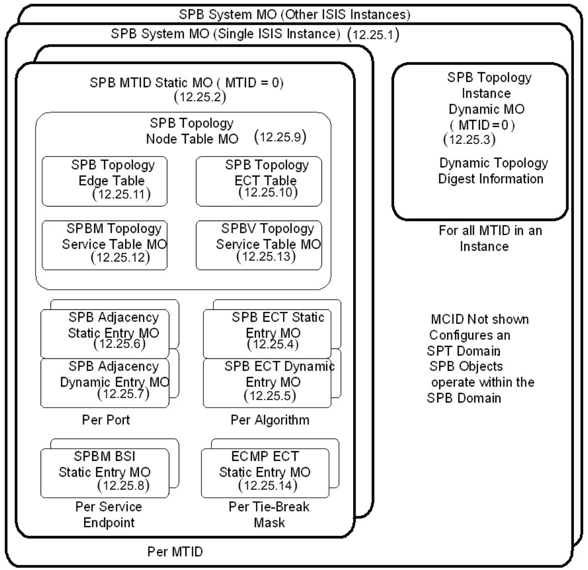
Figure 12-3—SPB managed objects (MOs)
IS-IS provides a logical topology instance and within each instance the SPT Domain defines a set of managed objects. The following are the managed objects in an SPT Bridge:
a) The SPB System managed object (12.25.1)
b) The SPB MTID Static managed object (12.25.2) (see Multi-Topology Identifier (MTID) in Clause 3)
c) The SPB Topology Instance Dynamic managed object (12.25.3)
d) The SPB ECT Static Entry managed object (12.25.4)
e) The SPB ECT Dynamic Entry managed object (12.25.5)
f) The SPB Adjacency Static Entry managed object (12.25.6)
g) The SPB Adjacency Dynamic Entry managed object (12.25.7)
h) The SPBM BSI Static Entry managed object (12.25.8)
i) The SPB Topology Node Table managed object (12.25.9)
j) The SPB Topology ECT Table managed object (12.25.10)
k) The SPB Topology Edge Table managed object (12.25.11)
l) The SPBM Topology Service Table managed object (12.25.12)
m) The SPBV Topology Service Table managed object (12.25.13)
n) The ECMP ECT Static Entry managed object (12.25.14)
12.25.1 The SPB System managed object
There is one SPB System managed object per ISIS-SPB area supported by an SPT Bridge. A single area only is supported in this version of the specification. It contains the fundamental SPB configuration parameters for the Bridge. It is persistent over reboot. The management operations that can be performed on the SPB System managed object are as follows:
a) Create SPB System managed object (12.25.1.1)
b) Write SPB System managed object (12.25.1.2)
c) Read SPB System managed object (12.25.1.3)
d) Delete SPB System managed object (12.25.1.4)
12.25.1.1 Create SPB System Managed object
12.25.1.1.1 Purpose
To create and configure the SPB System managed object on a Bridge.
12.25.1.1.2 Inputs
a) The part of the IS-IS Area Address that is domain specific (see Figure 4, ISO/IEC 10589:2002). This shall be set to zero in this version of this specification whenever SPB is the only protocol being supported by this IS-IS instance.
b) The MAC address to be used as the SPB System Identifier by all instances of ISIS-SPB on this Bridge. The System ID defaults to the Bridge Address if this input is not provided. The Bridge Address is the value returned by item a) of Discover Bridge (12.4.1.1.3) and Read Bridge (12.4.1.2.3).
c) The Group address used to address this ISIS-SPB instance (see Table 8-13). This address is configured to manage the transparency to ISIS-SPB of neighboring network elements, and also to specify the IS-IS Level at which this SPB instance is operating, which shall be Level 1 in this version of this specification.
12.25.1.1.3 Outputs
a) Operation status. This takes one of the following values:
1) Operation rejected because the specified IS-IS Area Address is already in use;
2) Operation rejected because the provided Group address does not correspond to an allowed address (Table 8-13);
3) Operation rejected because the specified SPB System Identifier value is not valid;
4) Operation rejected due to the Bridge’s inability to support the requested IS-IS Level; or
5) Operation accepted.
12.25.1.2 Write SPB System managed object
12.25.1.2.1 Purpose
To configure an SPB System managed object on a Bridge.
12.25.1.2.2 Inputs
a) The part of the IS-IS Area Address that is domain specific (see Figure 4, ISO/IEC 10589:2002). This shall be zero in this version of this specification.
b) The SPB System Shortest Path Source Identifier (SPSourceID) (27.10).
c) If SPBV mode is used, whether the SPVIDs associated with this Bridge are assigned, or are to be auto-allocated. The use of SPBV mode is inferred from the assignment of at least one VID to the reserved MSTID value 0xFFD (27.4) in the FID to MSTID Allocation Managed Object (12.12.2.2).
d) If SPBM mode is used, whether the SPsourceID associated with this Bridge is assigned, or is to be auto-allocated. The use of SPBM mode is inferred from the assignment of at least one VID to the reserved MSTID value 0xFFC (27.4) in the FID to MSTID Allocation Managed Object (12.12.2.2).
e) The agreement digest Convention identifier (28.4.3), specifying the agreement rules being used. It can take the values 1 to 3 as specified in 28.4.3.
12.25.1.2.3 Outputs
a) Operation status. This takes one of the following values:
1) Operation rejected due to the Bridge’s inability to support the requested SPB capability; or
2) Operation accepted.
12.25.1.3 Read SPB System managed object
12.25.1.3.1 Purpose
To obtain information about SPB System managed object on a Bridge.
12.25.1.3.2 Inputs
a) The part of the IS-IS Area Address that is domain specific (see Figure 4, ISO/IEC 10589:2002).
12.25.1.3.3 Outputs
a) The part of the IS-IS Area Address that is domain specific (see Figure 4, ISO/IEC 10589:2002).
b) The SPB System Identifier used by all instances of ISIS-SPB on this Bridge.
c) The Group address used to address this ISIS-SPB instance (Table 8-13). This address also identifies the IS-IS Level at which this SPB instance is operating.
d) The SPB System Name used by all instances of ISIS-SPB. This takes the value configured by Set Bridge Name (12.4.1.3) and which can also be read as item b) of Read Bridge (12.4.1.2).
e) The Bridge Priority (13.26.2). The value used by SPB is set in the CIST Bridge Protocol Parameters (12.8.1.3).
f) The SPB System SPSourceID (27.10).
g) The SPBV Mode, identifying whether, if SPBV mode is used, the SPVIDs associated with this Bridge are assigned, or are to be auto-allocated.
h) The SPBM Mode, identifying whether, if SPBM mode is used, the SPsourceID associated with this Bridge is assigned, or is to be auto-allocated.
i) The agreement digest Convention identifier (28.4.3), specifying the agreement rules being used.
12.25.1.4 Delete SPB System managed object
12.25.1.4.1 Purpose
To delete the SPB System managed object on a Bridge, so disabling it as an SPT Bridge.
12.25.1.4.2 Inputs
a) The part of the IS-IS Area Address that is domain specific (see Figure 4, ISO/IEC 10589:2002).
12.25.1.5 Outputs
a) Operation status. This takes one of the following values:
1) Operation rejected because one or more SPB MTID Static managed objects still exist and have not been deleted for this SPB instance; or
2) Operation accepted.
12.25.2 The SPB MTID Static managed object
There is one SPB MTID Static managed object per IS-IS Multi-Topology Identifier (MTID) used for SPB operation. It contains the SPB MTID value and the ISIS-SPB Overload flag for this MTID. It is persistent over reboot. The management operations that can be performed on the SPB MTID Static managed object are as follows:
a) Create SPB MTID Static managed object (12.25.2.1)
b) Write SPB MTID Static managed object (12.25.2.2)
c) Read SPB MTID Static managed object (12.25.2.3)
d) Delete SPB MTID Static managed object (12.25.2.4)
12.25.2.1 Create SPB MTID Static managed object
12.25.2.1.1 Purpose
To create and configure an SPB MTID Static managed object on a Bridge.
12.25.2.1.2 Inputs
a) An MTID to support IS-IS MT operation.
12.25.2.1.3 Outputs
a) Operation status. This takes one of the following values:
1) Operation rejected because the MTID is already in use; or 2) Operation accepted.
b) A Topology Index value that uniquely identifies this MTID Static managed object.
12.25.2.2 Write SPB MTID Static managed object
12.25.2.2.1 Purpose
To configure an SPB MTID Static managed object.
12.25.2.2.2 Inputs
a) An MTID to support IS-IS MT operation.
b) The Overload flag value, which has ISIS “no transit” semantics, applied only in this SPB topology.
12.25.2.2.3 Outputs
a) The MTID value.
b) The Overload flag value, which has ISIS “no transit” semantics, but applied only in this SPB topology.
12.25.2.3 Read SPB MTID Static managed object
12.25.2.3.1 Purpose
To obtain information about an SPB MTID Static managed object.
12.25.2.3.2 Inputs
a) An MTID to support IS-IS MT operation.
12.25.2.3.3 Outputs
a) The MTID value.
b) The Overload flag value, which has ISIS “no transit” semantics, but applied only in this SPB topology.
c) A Topology Index value that uniquely identifies this MTID Static managed object.
12.25.2.4 Delete SPB MTID Static managed object
12.25.2.4.1 Purpose
To delete an SPB MTID Static managed object.
12.25.2.4.2 Inputs
a) An MTID to support IS-IS MT operation.
12.25.2.4.3 Outputs
a) Operation status. This takes one of the following values:
Operation rejected because not all peer links in the SPB Adjacency Static Entry managed object for this MTID have an Administrative State of Disabled; or
2) Operation accepted.
12.25.3 The SPB Topology Instance Dynamic managed object
There is one SPB Topology Instance Dynamic managed object for each SPB MTID Static managed object. It contains the dynamic parameters computed for this Bridge as a consequence of its participation in SPB in the ISIS-SPB topology defined by the specified MTID within this instance of SPB. This object is automatically created as a consequence of the creation of the SPB MTID Static managed object associated with the topology. It is deleted with the deletion of the SPB MTID Static managed object associated with the topology. The management operations that can be performed on the SPB Topology Instance Dynamic managed object are as follows:
a) Read SPB Topology Instance Dynamic managed object
12.25.3.1 Read SPB Topology Instance Dynamic managed object
12.25.3.1.1 Purpose
To obtain information about the dynamic parameters computed by this Bridge as a consequence of its participation in SPB in the ISIS-SPB topology defined by the specified MTID within this instance of SPB.
12.25.3.1.2 Inputs
a) A Topology Index value that uniquely identifies a topology instance.
12.25.3.1.3 Outputs
a) The Topology Index value that uniquely identifies this topology instance.
b) The value of the topology Agreement Digest (13.17.1) being advertised by this Bridge to its peers in this ISIS-SPB Topology. This includes all parameters defined in the Agreement Digest (28.4).
c) The value of the MCID (8.9, 13.5, 13.8) being advertised by this Bridge to its peers.
d) The value of the Auxiliary MCID (27.4.1, 28.12.2) being advertised by this Bridge to its peers.
12.25.4 The SPB ECT Static Entry managed object
There is one SPB ECT Static Entry managed object per Base VID allocated to SPB operation. A Base VID exists in the context of a single ISIS-SPB MTID. The static Entry contains the SPB configuration parameters for the forwarding plane associated with the Base VID. It is persistent over reboot. The management operations that can be performed on the ECT Static Entry managed object are as follows:
a) Create an SPB ECT Static Entry managed object (12.25.4.1)
b) Read an SPB ECT Static Entry managed object (12.25.4.2)
c) Delete an SPB ECT Static Entry managed object (12.25.4.3)
12.25.4.1 Create SPB ECT Static Entry managed object
12.25.4.1.1 Purpose
To create and configure and interrogate an SPB ECT Static Entry managed object on a Bridge.
12.25.4.1.2 Inputs
a) A Topology Index value that uniquely identifies a topology instance.
b) A Base VID. This VID must have been assigned either to the reserved MSTID value 0xFFC for SPT Bridges in SPBM operation, or to the reserved MSTID value 0xFFD for SPBV (27.4) in the FID to MSTI Allocation table (12.12.2.2).
c) The identifier of the ECT Algorithm (ECT-ALGORITHM) to be used for this Base VID (Table 28- 1, Table 44-1). The Default is the LowPATHID 00-80-C2-01 (28.8).
d) The pre-configured value of the SPVID assigned to this Bridge if operating in SPBV mode. This input is ignored if auto-allocated is selected [item c) in 12.25.1.2.2]. This VID value must have been assigned to the reserved MSTID value 0xFFF (27.4) in the FID to MSTI Allocation Managed Object (12.12.2.2).
12.25.4.1.3 Outputs
a) Operation status. This takes one of the following values:
1) Operation rejected because the Topology Index value is not defined;
2) Operation rejected because the Base VID is already in use;
3) Operation rejected due to requested Base VID not assigned to specified SPB use;
4) Operation rejected due to requested SPVID not assigned to the SPBV pool; or
5) Operation accepted.
12.25.4.2 Read SPB ECT Static Entry managed object
12.25.4.2.1 Purpose
To obtain information about the SPB ECT Static Entry managed object for a Base VID.
12.25.4.2.2 Inputs
a) A Topology Index value that uniquely identifies a topology instance.
b) A Base VID. The value 4095 is a wildcard indicating that information, from any Base VID assigned to SPB operation, is requested.
12.25.4.2.3 Outputs
a) Operation status. This takes one of the following values:
1) Operation rejected because the Base VID is not assigned to SPB use; or
2) Operation accepted.
b) A Topology Index value that uniquely identifies this topology instance.
c) The Base VID.
d) The identifier of the ECT algorithm (ECT-ALGORITHM) to be used for this Base VID.
e) The value of the SPVID to be used by this Bridge for this Base VID if operating in SPBV mode.
12.25.4.3 Delete SPB ECT Static Entry managed object
12.25.4.3.1 Purpose
To delete the SPB ECT Static Entry managed object for a Base VID.
12.25.4.3.2 Inputs
a) A Topology Index value that uniquely identifies a topology instance.
b) A Base VID.
12.25.4.3.3 Outputs
a) Operation status. This takes one of the following values:
1) Operation rejected because the Bridge has services currently assigned to this Base VID;
2) Operation rejected because the SPT Region has services currently using this Base VID; or
3) Operation accepted.
12.25.5 The SPB ECT Dynamic Entry managed object
There is one SPB ECT Dynamic Entry managed object per Base VID allocated to SPB operation. It contains the SPB dynamic parameters associated with the Base VID. This object is automatically created as a consequence of the creation of the SPB ECT Static Entry managed object. It is deleted with the deletion of the SPB ECT Static Entry managed object. The management operations that can be performed on the ECT Dynamic Entry managed object are as follows:
a) Read SPB ECT Dynamic Entry managed object
12.25.5.1 Read SPB ECT Dynamic Entry managed object
12.25.5.1.1 Purpose
To obtain information about the SPB ECT Dynamic Entry managed object for a Base VID.
12.25.5.1.2 Inputs
a) A Topology Index value that uniquely identifies a topology instance.
b) A Base VID. The value 4095 is a wildcard indicating that information, from any Base VID assigned to SPB operation, is requested.
12.25.5.1.3 Outputs
a) The Topology Index value that uniquely identifies this topology instance.
b) The Base VID.
c) A flag identifying whether the operational mode of this Base VID is SPBV or SPBM.
d) A flag indicating that this Bridge has services currently assigned to this Base VID.
e) A flag indicating that the SPT Region has services currently using this Base VID.
f) A count of the number of ingress check failures (an error condition) on this Base VID since creation of this SPB ECT Dynamic Entry managed object.
12.25.6 The SPB Adjacency Static Entry managed object
There is one SPB Adjacency Static Entry managed object per port per ISIS-SPB topology. It contains the SPB configuration parameters for the port in a topology. It is persistent over reboot. The management operations that can be performed on the SPB Adjacency Static Entry managed object are as follows:
a) Write SPB Adjacency Static Entry managed object (12.25.6.1)
b) Read SPB Adjacency Static Entry managed object (12.25.6.2)
12.25.6.1 Write SPB Adjacency Static Entry managed object
12.25.6.1.1 Purpose
To configure an SPB Adjacency Static Entry managed object on a port for an ISIS-SPB topology.
12.25.6.1.2 Inputs
a) A Topology Index value that uniquely identifies a topology instance.
b) The system interface index of a port.
c) The value of the ieee802.1 SPB Link State metric for the link on this port. For MTID = 0, or when a single MTID only is in use, this value should be set equal to the Path Cost set in the CIST Port Parameters Managed Object (see 12.8.2.1 and 12.8.2.3).
d) The SPB administrative state of a port.
NOTE—Item c) – The primary function of IS-IS MT is to allow different link metrics to be associated with each topology, so that different routes are preferentially favored in different topologies. However, care must be taken when configuring IS-IS MT that CIST path costs are assigned to one topology, and that this topology is the one used to compute the CIST, in order that SPB calculates its part of the CIST consistently.
12.25.6.1.3 Outputs
a) The Topology Index value that uniquely identifies this topology instance.
b) The system interface index of the port.
c) The value of the ieee802.1 SPB Link State metric for the link on this port.
d) The SPB administrative state of this port.
12.25.6.2 Read SPB Adjacency Static Entry managed object
12.25.6.2.1 Purpose
To read back the parameters of an SPB Adjacency Static Entry managed object on a port for an ISIS-SPB topology.
12.25.6.2.2 Inputs
a) A Topology Index value that uniquely identifies a topology instance.
b) The system interface index of a port. The value of zero is a wildcard indicating information, for any interface on which SPB operation is enabled, is requested.
12.25.6.2.3 Outputs
a) The Topology Index value that uniquely identifies this topology instance.
b) The system interface index of the port.
c) The value of the ieee802.1 SPB Link State metric for the link on this port.
d) The SPB administrative state of this port.
12.25.7 The SPB Adjacency Dynamic Entry managed object
There is one SPB Adjacency Dynamic Entry managed object per port per ISIS-SPB topology. It contains the dynamically discovered SPB parameters for the port in that topology. The management operations that can be performed on the SPB Adjacency Dynamic Entry managed object are as follows:
a) Read SPB Adjacency Dynamic Entry managed object in a topology.
12.25.7.1 Read SPB Adjacency Dynamic Entry managed object
12.25.7.1.1 Purpose
To obtain information about an SPB Adjacency Dynamic Entry managed object on a port.
12.25.7.1.2 Inputs
a) A Topology Index value that uniquely identifies a topology instance.
b) The system interface index of a port. The value of zero is a wildcard indicating information, for any interface on which SPB operation is enabled, is requested.
c) The SPB System Identifier of a peer attached to the port.
12.25.7.1.3 Outputs
a) The Topology Index value that uniquely identifies this topology instance.
b) The system interface index of the port.
c) The SPB System Identifier of the peer attached to the port.
d) The Bridge Port Number (same as item d)1), 12.4.1.2.3).
e) The SPB operational state of this port.
f) The IS-IS System name of the peer attached to the port.
g) The value of the topology Agreement Digest (13.17.1) being advertised by the peer. This includes all parameters defined in the Agreement Digest (28.4).
h) The value of the MCID (8.9, 13.5, 13.8) being advertised by the peer.
i) The value of the Auxiliary MCID (27.4.1, 28.12.2) being advertised by the peer.
j) The value of the Local Circuit ID of this node, used by ISIS to select a single adjacency if more than one link connects a pair of SPT Bridges.
k) The value of the Local Circuit ID of the peer node, used by ISIS to select a single adjacency if more than one link connects a pair of SPT Bridges.
l) The value of the Port Identifier on this node for the link selected by ISIS to form the adjacency, equal to the value read as item c) from the CIST Port Parameters Managed Object (see 12.8.2.1) on this node.
m) The value of the Port Identifier on the peer node for the link selected by ISIS to form the adjacency with this node.
n) An index pointing into the isisCircTable in the IS-IS MIB for cross-referencing.
12.25.8 The SPBM BSI Static Entry managed object
There is one SPBM BSI Static Entry managed object for each I-SID assigned to an SPBM VID on a CBP. It contains the SPBM configuration parameters for an I-SID. It is persistent over reboot. The management operations that can be performed on the SPBM BSI Static Entry managed object are as follows:
a) Write SPBM BSI Static Entry managed object (12.25.8.1)
b) Read SPBM BSI Static Entry managed object (12.25.8.2)
12.25.8.1 Write SPBM BSI Static Entry managed object
12.25.8.1.1 Purpose
To configure an SPBM BSI Static Entry managed object for an I-SID assigned to an SPBM VID on a CBP.
12.25.8.1.2 Inputs
a) A Topology Index value which uniquely identifies a topology instance.
b) The system interface index of a CBP.
c) The I-SID identifying the backbone service instance.
d) A B-VID associated with this I-SID. There may be more than one object for a given I-SID, allowing it to be associated with multiple B-VIDs. This B-VID may differ from the B-VID specified in 12.16.5.2 that governs the VID assigned to the I-SID at the CBP; for example, to allow changing ISIS-SPB parameters when moving an I-SID from one B-VID to another. The B-VID to I-SID association in this managed object is advertised in ISIS-SPB so that forwarding state for the association is installed throughout the SPT domain, in addition to CBP state installed by 12.16.5.2. It is only the B-VID defined in 12.16.5.2 on which a CBP transmits; however, a CBP must receive from any B-VID with which its I-SID has an association.
e) Multicast transmit indication bit [item e) in 28.12.10].
f) Multicast receive indication bit [item f) in 28.12.10].
g) Shared tree transmit indication bit [item g) in 28.12.10].
h) Tie-Break Mask value [item h) in 28.12.10].
12.25.8.1.3 Outputs
a) Operation status. This takes one of the following values:
1) Operation rejected because the Topology Index value is not defined;
2) Operation rejected because the identified port does not exist or is not a CBP;
3) Operation rejected because the I-SID is not assigned to an SPBM VID; or
4) Operation accepted.
12.25.8.2 Read SPBM BSI Static Entry managed object
12.25.8.2.1 Purpose
To read back the parameters of an SPBM BSI Static Entry managed object for an I-SID assigned to an SPBM VID on a CBP.
12.25.8.2.2 Inputs
a) A Topology Index value that uniquely identifies a topology instance.
b) The system interface index of a CBP. The value of zero is a wildcard indicating information, for any interface on which SPB operation is enabled, is requested.
c) An I-SID identifying a backbone service instance. The value 0xFFFFFF is a wildcard indicating that information on all I-SIDs on the specified port(s) is requested.
d) A B-VID associated with this I-SID. The value 4095 is a wildcard indicating that information for any B-VID associated with the specified I-SID(s) is requested.
12.25.8.2.3 Outputs
a) Operation status—this takes one of the following values:
1) Operation rejected because the Topology Index value is not defined;
2) Operation rejected because the identified port does not exist or is not a CBP;
3) Operation rejected because the I-SID is not assigned to an SPBM VID; or
4) Operation accepted.
b) The Topology Index value that uniquely identifies this topology instance.
c) The system interface index of the port.
d) The I-SID identifying a backbone service instance.
e) The B-VID associated with this I-SID.
f) Multicast transmit indication bit [item e) in 28.12.10].
g) Multicast receive indication bit [item f) in 28.12.10].
h) Shared tree transmit indication bit [item g) in 28.12.10].
i) Tie-Break Mask value [item h) in 28.12.10].
If item b) in 12.25.8.2.2 is configured with the value 0, a list indexed by the CBP ports on the system containing items a) to i) [with the exception of item a2)].
12.25.9 The SPB Topology Node Table managed object
There is one SPB Topology Node Table managed object per Bridge per ISIS-SPB topology. It is populated by ISIS-SPB with the nodal SPB parameters discovered for all SPT Bridges participating in that topology within the SPT Region. This object is automatically created as a consequence of the creation of the SPB MTID Static managed object for that topology. It is deleted with the deletion of that SPB MTID Static managed object. The management operations that can be performed on the SPB Topology Node Table managed object are as follows:
a) Read SPB Topology Node Table managed object
12.25.9.1 Read SPB Topology Node Table managed object
12.25.9.1.1 Purpose
To obtain nodal information about all SPT Bridges in an SPT Region for an ISIS-SPB topology.
12.25.9.1.2 Inputs
a) A Topology Index value that uniquely identifies a topology instance.
b) The SPB System Identifier of ISIS-SPB on a remote Bridge. The value zero is a wildcard indicating that information, from all remote Bridges in the SPT region, is requested.
12.25.9.1.3 Outputs
A list, which may be empty, comprising one entry for each Bridge within the SPT Region of which the local IS-IS instance is aware. Each entry contains the following information about a remote Bridge:
a) The Topology Index value that uniquely identifies this topology instance.
b) The SPB System Identifier of ISIS-SPB on the remote Bridge.
c) The Bridge Priority [the value set in CIST Protocol Parameters (12.8.1.3) for the remote Bridge].
d) The SPSourceID (27.10) of the remote Bridge.
e) The SPB System Name of the remote Bridge.
If b) identifies a specific remote Bridge then the list above will comprise one entry per Base VID, as specified in item c), containing only information about the specific remote Bridge.
12.25.10 The SPB Topology ECT Table managed object
There is one SPB Topology ECT Table managed object per Bridge per ISIS-SPB topology. It is populated by ISIS-SPB with the nodal ECT parameters discovered for all SPT Bridges participating in that topology within the SPT Region. This object is automatically created as a consequence of the creation of the SPB MTID Static managed object. It is deleted with the deletion of that SPB MTID Static managed object. The management operations that can be performed on the SPB Topology ECT Table managed object are as follows:
a) Read SPB Topology ECT Table managed object
12.25.10.1 Read SPB Topology ECT Table managed object
12.25.10.1.1 Purpose
To obtain nodal ECT information, including the binding of ECT Algorithms to Base VIDs, about all SPT Bridges in an SPT Region for an ISIS-SPB topology.
12.25.10.1.2 Inputs
a) A Topology Index value that uniquely identifies a topology instance.
b) The SPB System Identifier of ISIS-SPB on a remote Bridge. The value zero is a wildcard indicating information, for all System identifiers, is requested.
c) The Base VID. The value 4095 is a wildcard indicating that information, from any Base VID assigned for SPB operation, is requested.
12.25.10.1.3 Outputs
A list, which may be empty, comprising one entry for each Bridge within the SPT Region of which the local ISIS-SPB instance is aware. Each entry contains the following information about a remote Bridge:
a) The Topology Index value that uniquely identifies this topology instance.
b) The SPB System Identifier of ISIS-SPB on the remote Bridge.
c) The Base VID.
d) The identifier of the ECT Algorithm being used.
e) The SPB operational mode (SPBV or SPBM).
f) The SPVID allocation mode (manual or automatic).
g) The value of the SPVID when operating in SPBV mode.
h) A flag indicating that this Bridge has services currently assigned to this Base VID.
If item b) identifies a specific remote Bridge then the list above will comprise one entry per Base VID as specified in item c), containing only information about the specific remote Bridge.
12.25.11 The SPB Topology Edge Table managed object
There is one SPB Topology Edge Table managed object per Bridge per ISIS-SPB topology. It is populated by ISIS-SPB with the discovered Edge (link) parameters for that topology within the SPT Region, referenced by the System Identifiers of the pair of SPT Bridges forming the end-points. This object is automatically created as a consequence of the creation of the SPB MTID Static managed object for that topology. It is deleted with the deletion of that SPB MTID Static managed object. The management operations that can be performed on the SPB Topology Edge Table managed object are as follows:
a) Read SPB Topology Edge Table managed object
12.25.11.1 Read SPB Topology Edge Table managed object
12.25.11.1.1 Purpose
To obtain information about all Edges interconnecting SPT Bridges within an SPT Region for an ISIS-SPB topology.
NOTE—The use of the ISIS Local Circuit ID for tie breaking enables a single Edge (adjacency) per node pair and a unique Port Identifier on each node for spanning tree compatibility; refer to 28.11 and the Read operation on SPB Adjacency Dynamic Entry managed object.
12.25.11.1.2 Inputs
a) A Topology Index value that uniquely identifies a topology instance.
b) The SPB System Identifier used by the near Bridge on an Edge. The value zero is a wildcard indicating information, for all System identifiers, is requested.
c) The SPB System Identifier used by the far Bridge on an Edge. The value zero is a wildcard indicating information, for all System identifiers, is requested.
12.25.11.1.3 Outputs
A list, which may be empty, comprising one entry for each Edge within the SPT Region of which the local IS-IS instance is aware. Each entry contains the following information about an Edge:
a) The Topology Index value that uniquely identifies this topology instance.
b) The SPB System Identifier used by the near Bridge on the Edge.
c) The SPB System Identifier used by the far Bridge on the Edge.
d) The value of the ieee802.1 SPB Link State metric for this Edge, which is being advertised by the near Bridge.
e) The value of the ieee802.1 SPB Link State metric for this Edge, which is being advertised by the far Bridge.
NOTE—The terms “near” and “far” are used locally solely to distinguish the two ends of the Edge and associated metric values, and do not signify any relationship between the SPT Bridges advertising the Edge and the local Bridge supporting the SPB Topology Edge Table managed object. As a consequence of this definition, in a stable topology two Edges are created per physical link, one advertised in a Link State PDU (LSP) by each Bridge.
12.25.12 The SPBM Topology Service Table managed object
There is one SPBM Topology Service Table managed object per Bridge per ISIS-SPB topology. It is populated by ISIS-SPB with the mapping of Service instances to SPT Bridges operating in SPBM mode participating in that topology discovered within the SPT Region. This object is automatically created as a consequence of the creation of the SPB MTID Static managed object for that topology. It is deleted with the deletion of that SPB MTID Static managed object. The SPBM Topology Service Table managed object only exists to provide Region-wide visibility of I-SID instance locations. Configuration of local I-SID instances is performed using the BEB Management (12.16) and the mapping of VIPs to PIPs (and hence to the B-MAC address associated with an I-SID) by PIP Management (12.16.4).
The management operations that can be performed on the SPBM Topology Service Table managed object are as follows:
a) Read SPBM Topology Service Table managed object
12.25.12.1 Read SPBM Topology Service Table managed object
12.25.12.1.1 Purpose
To obtain information about the location of all I-SID instances within an SPT Region in an ISIS-SPB topology.
12.25.12.1.2 Inputs
a) A Topology Index value that uniquely identifies a topology instance.
b) The SPB System Identifier of an SPT Bridges operating in SPBM mode hosting an I-SID. The value zero is a wildcard indicating information, from all remote Bridges in the SPT region hosting any I-SIDs, is requested.
c) An I-SID value. The value 0xFFFFFF is a wildcard indicating that information, from the remote Bridge(s) specified in item b) above hosting any I-SID, is requested.
d) The Base VID associated with this I-SID instance. The value 4095 is a wildcard indicating that information, from any Base VID assigned to SPB operation, is requested.
12.25.12.1.3 Outputs
A list, which may be empty, comprising one entry for each I-SID assigned to a Base VID within the SPT Region of which the local IS-IS instance is aware. Each entry contains the following information about the I-SID:
a) The Topology Index value that uniquely identifies this topology instance.
b) The SPB System Identifier of the SPT Bridges operating in SPBM mode hosting an I-SID instance.
c) The I-SID value.
d) The Base VID associated with this I-SID (and hence the ECT-ALGORITHM applied to this service).
e) The B-MAC address associated with this I-SID. If multiple I-SID instances are configured on a single Bridge but are reachable by different B-MAC addresses, a separate record is returned for each B-MAC address associated with that I-SID.
f) The I-SID instance service characteristic; transmit-only, receive-only, or both [item e) and item f) in 28.12.10; item e) and item f) in 12.25.8.1].
g) If ECMP is supported, the shared tree transmit indication [item g) in 28.12.10; item g) in 12.25.8.1.2].
h) If ECMP is supported, the Tie-Break Mask value [item h) in 28.12.10; item h) in 12.25.8.1.2].
NOTE—In general, an I-SID will be assigned to a single Base VID. During the administratively mediated migration of traffic from one ECT-ALGORITHM to a new one, an I-SID may be assigned to two Base VIDs for the duration of the transition in order to achieve loss-less migration (28.9.2).
12.25.13 The SPBV Topology Service Table managed object
There is one SPBV Topology Service Table managed object per Bridge per ISIS-SPB topology. It is populated by ISIS-SPB with the mapping of group MAC addresses to SPT Bridges operating in SPBV mode participating in that topology discovered within the SPT Region. This object is automatically created as a consequence of the creation of the SPB MTID Static managed object. It is deleted with the deletion of that SPB MTID Static managed object. The SPBV Topology Service Table managed object only exists to provide Region-wide visibility of group MAC address instance locations. Local configuration of group MAC address instances is performed using the procedures for management of Static Filtering Entries (12.7.2), or MMRP procedures (10.9).
The management operations that can be performed on the SPBV Topology Service Table managed object are as follows:
a) Read SPBV Topology Service Table managed object
12.25.13.1 Read SPBV Topology Service Table managed object
12.25.13.1.1 Purpose
To obtain information about all group MAC address instances within an SPT Region in an ISIS-SPB topology.
12.25.13.1.2 Inputs
a) A Topology Index value that uniquely identifies a topology instance.
b) The SPB System Identifier of an SPT Bridges operating in SPBV mode hosting a group MAC address. The value zero is a wildcard indicating information, from all remote Bridges in the SPT region hosting group MAC addresses, is requested.
c) The group MAC address value. The value zero is a wildcard indicating information, about all Group MACs for the specific Bridge(s) with the System Identifier as specified by item b), is requested.
12.25.13.1.3 Outputs
A list, which may be empty, and comprising one entry for each group MAC address instance within the SPT Region of which the local IS-IS instance is aware. Each entry contains the following information about the group MAC address:
a) The Topology Index value that uniquely identifies this topology instance.
b) The SPB System Identifier of the SPT Bridges operating in SPBV mode hosting a group MAC address instance.
c) The group MAC address value.
d) The Base VID (and hence ECT-ALGORITHM applied to this service).
e) The group MAC address instance service characteristic; transmit-only, receive-only, or both.
If item b) identifies a specific remote Bridge hosting an group address, then the list above will comprise only information about the specific remote Bridge.
12.25.14 The ECMP ECT Static Entry managed object
There is one ECMP ECT Static Entry managed object per Tie-Break Mask. It contains the Bridge Priority to be used for shared tree root selection for that Tie-Break Mask value. It is persistent over reboot. The management operations that can be performed on the ECMP ECT Static Entry managed object are as follows:
a) Write ECMP ECT Static Entry managed object (12.25.14.1)
b) Read ECMP ECT Static Entry managed object (12.25.14.2)
12.25.14.1 Write ECMP ECT Static Entry managed object
12.25.14.1.1 Purpose
To configure a different Bridge Priority to be used solely for shared tree root selection for a given Tie-Break Mask (28.12.6.1, 28.8).
12.25.14.1.2 Inputs
a) A Topology Index value which uniquely identifies a topology instance.
b) A Tie-Break Mask value [item d) in 28.12.6.1].
c) Bridge Priority [item e) in 28.12.6.1].
12.25.14.1.3 Outputs
a) Operation status. This takes one of the following values:
1) Operation rejected because the Topology Index value is not defined; or
2) Operation accepted.
12.25.14.2 Read ECMP ECT Static Entry managed object
12.25.14.2.1 Purpose
To read back the Bridge Priority for a given Tie-Break Mask.
12.25.14.2.2 Inputs
a) A Topology Index value that uniquely identifies a topology instance.
b) A Tie-Break Mask value [item d) in 28.12.6.1].
12.25.14.2.3 Outputs
a) Operation status—this takes one of the following values:
1) Operation rejected because the Topology Index value is not defined; or
2) Operation accepted.
b) The Topology Index value that uniquely identifies this topology instance.
c) The Tie-Break Mask value [item d) in 28.12.6.1].
d) The Bridge Priority [item e) in 28.12.6.1].
12.26 Edge Virtual Bridging (EVB) management
The conformance requirements for EVB Bridges and EVB stations are defined in 5.23 and 5.24, respectively. Each C-VLAN component, ER (5.24.1), and Port-mapping S-VLAN component can be managed using the managed objects of 12.4 through 12.12 along with the EVB managed objects specified in this subclause.
An EVB Bridge system (Figure 12-4) supports the EVB managed objects defined in 12.26.1 through 12.26.3 and 12.27. Optionally, an EVB Bridge supports the managed objects for S-channels defined in 12.26.4.
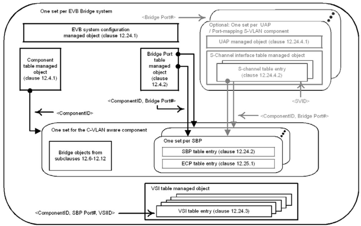
Figure 12-4—Relationships among EVB Bridge managed objects
An EVB station system (Figure 12-5) supports the EVB managed objects defined in 12.26.1, 12.26.3, 12.26.5, and 12.27. Optionally, an EVB station supports the managed objects for S-channels defined in 12.26.4.
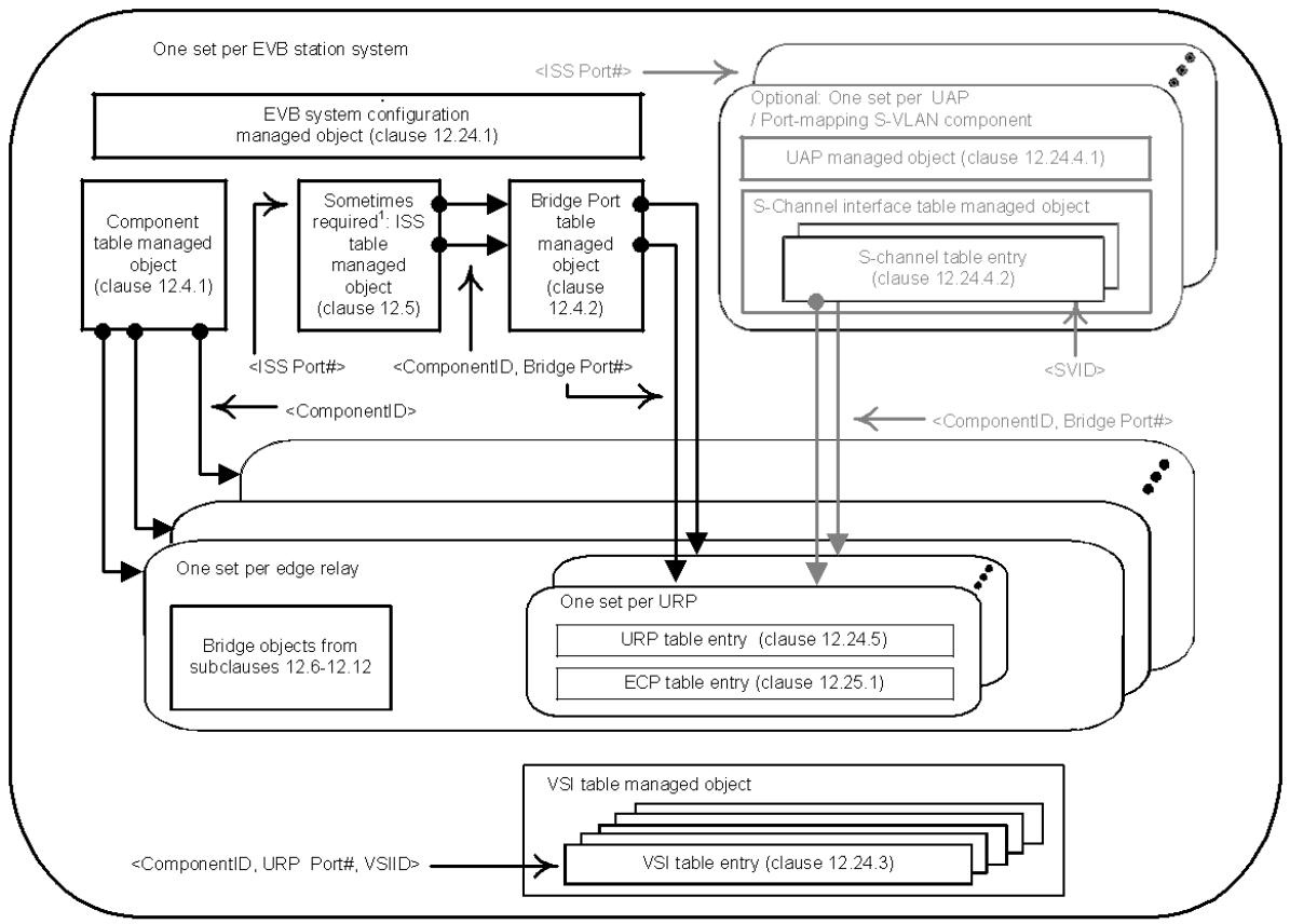
Note 1: ISS table managed object is required when URP Port# I= ISS Port#
Figure 12-5—Relationship among EVB station managed objects
The EVB-specific managed objects defined here:
a) Provide managed objects for identifying and configuring an EVB system and its system-wide default parameters for LLDP, Virtual Station Interface (VSI) Discovery and Configuration Protocol (VDP), and S-channel (12.26.1).
Provide managed objects for configuring the Station-facing Bridge Ports (SBPs) of EVB Bridges (12.26.2).
c) Provide a VSI table that contains the current VSI and VDP state for each VSI that is active in the EVB system (12.26.3).
d) Provide managed objects for configuring the Port-mapping S-VLAN components and S-channels (12.26.4).
e) Provide managed objects for configuring the URPs of the ERs (12.26.5).
For each EVB system, an EVB system configuration managed object exists containing the system-wide defaults used to initialize the other EVB objects.
Every Port of the EVB system (40.1, 40.2, 40.3) is uniquely identified by a ComponentID (12.3) and Port Number (12.3) [which together identify a Port Index (12.3)]. In EVB systems where the ISS and bound Bridge Port have different Port Numbers, an ISS table (12.5.1) allows determining the associated Bridge
Port’s ComponentID and Port Number from the scalar ISS Port Number. An example where the ISS table would be needed is an EVB station where the station has multiple LANs each attaching to different ERs and where the ERs each use the same Port Number (however different ComponentIDs) to identify their URPs (Figure 40-3). The ISS table is normally not necessary in an EVB Bridge since the single C-VLAN aware component provides a Bridge Port Number that is unique within the EVB Bridge for every ISS, allowing the ISS and the Bridge Port to use the same Port Number independent from the ComponentID.
The ERs of an EVB station have two types of ports. Each ER DRP provides attachment to one or more VSIs. No special EVB objects are used to manage the DRPs. URPs can attach to a LAN that can be externally accessible or attach through an internal LAN to a CAP of an S-channel. URPs are managed using the URP table. Each URP table entry identifies a URP within the system and allows configuration and monitoring of LLDP and VDP for the URP (12.26.5). For each URP there is also a ECP table entry that allows configuration and monitoring of ECP (12.27).
NOTE 1—The most common case is that a single VSI is associated with each DRP.
The C-VLAN component of an EVB Bridge has two types of Ports. Each C-VLAN Bridge Port is externally accessible and does not provide any EVB capabilities. No special EVB objects are used to manage the C-VLAN Bridge Ports. Each SBP attaches to a LAN that can be externally accessible or attach though an internal LAN to a CAP of an S-channel. SBPs are managed using the SBP table. Each SBP table entry identifies a single SBP within the system and allows configuration and monitoring of LLDP and VDP for the SBP (12.26.2). For each SBP there is also a ECP table entry that allows configuration and monitoring of ECP (12.27).
Within each EVB station and EVB Bridge, a table holding the VSIs allows monitoring of the active VSIs (12.26.3). VSI table entries are keyed on the VSI Instance Identifier (VSIID) and the URP’s or SBP’s ComponentID and Port Number. During the movement of VSIs within the data center network (DCN) it is possible to have a transient condition where the same VSIID exists at two locations. When these two instances are at the same URP or SBP, they are indistinguishable; therefore, the table holds only the state for the most recent VSI command. However, when the movement is between different URPs or SBPs, the table will hold two copies of the same VSIID differentiated by the ComponentID and Port Number of the URPs or SBPs.
NOTE 2—In the case where a VSI is migrated between DRPs of the same ER, there is no reason to de-associate, as the table does not maintain any state that identifies the DRP of the ER to which the VSI is attached.
An association is identified by its URP and VSIID. If an association is established for a VSI, and a new association is established on the same URP for the same VSIID, then the new association replaces the old one. A subsequent de-association for that VSIID will remove the current association, regardless of the parameters.
In EVB systems supporting S-channels, the optional UAP table and S-channel interface table are used to configure and control the Port-mapping S-VLAN components and CDCP (12.26.4).
Each ISS that is bound to an Uplink Access Port (UAP) automatically has a Port-mapping S-VLAN component with a default S-channel (using S-VID 1). Each S-channel is identified by the ISS Port Number of the UAP and the S-VID, for SBPs, or S-channel Identifier (SCID), for URPs, identifying the S-channel. The default S-channel carries all the un-S-tagged traffic that traverses the Port-mapping S-VLAN component.
In an EVB Bridge system, S-channels are automatically connected to SBPs when the S-Channel is created. If the S-channel is the default S-channel, it is connected to the SBP with the same Port Number as the ISS bound to the UAP. If the S-channel is not the default S-channel, a new SBP is allocated to the S-channel (which has a Port Number different from any ISS Port Number where a UAP or C-VLAN Bridge Port could be bound) and connected to the CAP through an internal LAN (6.14). With CDCP enabled and operating in the $^ { \circ } \mathrm { B } ^ { \prime }$ role, the S-channel interface table entries are automatically created (deleted) by CDCP to fill requests from the peer CDCP operating the ‘S’ role.
In an EVB station, S-channels are connected to URPs by the operating system. The URP Port Numbers are not reserved, so the UAP’s ISS Port Number may not be the same as the URP Port Number. The operating system is not required to automatically attach each S-channel to a URP; however, it can if it chooses. The URP Port Numbers have no restrictions beyond the normal requirement that every relay port be uniquely identified in the EVB system by a ComponentID and Port Number pair. With CDCP enabled and operating in the ‘S’ role, CDCP uses the S-channel interface table to build requests for creating (deleting) S-channels from the peer CDCP operating in the $ { ^ \mathrm { c B } } ^ { \mathrm { , } }$ role and enables these S-channels after the peer grants an S-VID for use by the S-channel.
Management of the UAP, Port-mapping S-VLAN component and CDCP is achieved through the UAP table (12.26.4.1). The management of CAPs and their LAN attachments is accomplished by the S-channel interface table entries (12.26.4.2). A UAP table entry along with the Port-mapping S-VLAN creation rules specified in 12.26.4 are sufficient to manage the Port-mapping S-VLAN component. The Bridge managed objects in 12.4 through 12.12 can optionally be used, in addition to the objects of 12.26.4, to manage the Port-mapping S-VLAN components.
The following managed objects, illustrated in Figure 12-4 and Figure 12-5, define the semantics of the management operations specific to EVB Bridges and stations:
The EVB system base managed object (12.26.1)
The SBP table entry managed object (12.26.2)
— The VSI table entry managed object (12.26.3)
— The MAC/VID pair table entry managed object (12.26.3)
The UAP table entry managed object (12.26.4)
The S-channels interface table entry managed object (12.26.4)
— The URP table entry managed object (12.26.5)
12.26.1 EVB system base table
An instance of the EVB system base table (Table 12-17) can be implemented by an EVB Bridge or EVB station. It comprises the identifiers for an EVB system (Clause 40) and system-wide default parameters used to support EVB services (D.2.13, 6.6.1), VSI discovery (Clause 41), and ECP (43.3).
Table 12-17—EVB system base table
<table><tr><td>Name</td><td>Data type</td><td><eq>Operations\ supported^a</eq></td><td><eq>Conformance^b</eq></td><td>References</td></tr><tr><td>evbSysType</td><td>enumerated {sysB, sysS}</td><td>R</td><td>BE</td><td>5.23, 5.24</td></tr><tr><td>evbSysNumExternalPorts</td><td>unsigned [1...4095]</td><td>R</td><td>BE</td><td>12.4.2, 12.5.1</td></tr><tr><td></td><td></td><td></td><td></td><td></td></tr><tr><td>evbSysEvbLldpTxEnable</td><td>Boolean</td><td>RW</td><td>BE</td><td>D.2.13</td></tr><tr><td>evbSysEvbLldpManual</td><td>Boolean</td><td>RW</td><td>BE</td><td>D.2.13</td></tr><tr><td>evbSysEvbLldpGidCapable</td><td>Boolean</td><td>RW</td><td>BE</td><td>D.2.13</td></tr><tr><td></td><td></td><td></td><td></td><td></td></tr><tr><td>evbSysEcpDfltAckTimerInit</td><td>timer exp</td><td>RW</td><td>BE</td><td>D.2, 43.3.6.1</td></tr><tr><td>evbSysEcpDfltMaxTries</td><td>unsigned [0...7]</td><td>RW</td><td>BE</td><td>D.2, 43.3.7.4</td></tr><tr><td></td><td></td><td></td><td></td><td></td></tr><tr><td>evbSysVdpDfltRsrcWaitDelay</td><td>timer exp</td><td>RW</td><td>BE</td><td>D.2.13, 41.5.5.7</td></tr><tr><td>evbSysVdpDfltReinitKeepAlive</td><td>timer exp</td><td>RW</td><td>BE</td><td>D.2.13, 41.5.5.5</td></tr></table>
a R= Read-only access; RW = Read/Write access.
bB = Required for an EVB Bridge system; E = Required for an EVB station system.
The management operations that can be performed on an EVB system table entry are as follows:
a) Read EVB system table entry
b) Update EVB system table entry
12.26.1.1 System identifiers
The evbSysType identifies the system type. The enumerated types for evbSysType are
a) sysB—EVB Bridge
b) sysS—EVB station
12.26.1.2 System defaults for EVB
The parameters evbSysEvbLldpTxEnable and evbSysEvbLldpManual are used to initialize the LLDP EVB objects for new SBPs and URPs. When evbSysLldpTxEnable is TRUE, a new SBP or URP will place the local EVB objects in the LLDP nearest Customer database; when FALSE, a new SBP or URP will not place the local EVB objects in the LLDP database. When evbSysLldpManual is FALSE, the operating configuration will be determined by the comparison between the local and remote LLDP EVB objects (automatic), regardless of the setting of evbSysLldpTxEnable. When evbSysLldpManual is TRUE, the configuration will be determined by the setting of the local EVB objects only (manual).
The evbSysLldpGidCapable parameter indicates if the port is capable of processing GroupIDs. GroupIDs can be used if both the EVB Bridge and EVB station indicate they are capable by setting the EVB LLDP object for GroupID capable to TRUE. On an EVB Station this means the station can provide GroupIDs rather than VIDs in VDP requests and accept VIDs in response from the EVB Bridge. On an EVB Bridge this means the Bridge can provide a VID corresponding to the GroupID provided by the EVB station.
The default value for evbSysEcpDfltAckTimerInit is 14, which provides a time of 164 ms. Systems are not required to implement smaller times and can reject requests to set the timers to small times; however, systems are required to implement 14 and above to allow fall back to the longest time proposed by the EVB Bridge or EVB station.
The default value for evbSysVdpDfltRsrcWaitDelay and evbSysVdpDfltReinitKeepAlive is system dependant. All systems support the values of 20 and above, which provide times of 10.5 seconds and greater. Systems are not required to implement smaller times and can reject requests to set the timers to small times; however, systems are required to implement 20 and above to allow fall back to the longest time proposed by the EVB Bridge or EVB station.
Table 12-18 shows how the system defaults are used to initialize the parameters in the SBP, URP, and ECP table entries.
Table 12-18—EVB system parameter defaults
<table><tr><td>System parameter</td><td>Default value</td><td>LLDP, SBP, URP, ECP entry parameter</td></tr><tr><td>evbSysEvbLldpTxEnable</td><td>TRUE</td><td>LLDP Transmit Enable</td></tr><tr><td>evbSysEvbLldpManual</td><td>FALSE</td><td>sbpLldpManual, urpLldpManual</td></tr><tr><td>evbSysEvbLldpGidCapable</td><td>system dependant</td><td>LLDP GID Capable</td></tr><tr><td>evbSysEcpDfltAckTimerInit</td><td>14, for 164 milliseconds</td><td>ecpAdminAckTimerInit</td></tr><tr><td>evbSysEcpDfltMaxTries</td><td>3</td><td>ecpAdminMaxTries</td></tr><tr><td>evbSysVdpDfltRsrcWaitDelay</td><td>system dependant</td><td>sbpVdpAdminRsrcWaitDelay, urpVdpAdminRsrcWaitDelay</td></tr><tr><td>evbSysVdpDfltReinitKeepAlive</td><td>system dependant</td><td>sbpVdpAdminReinitKeepAlive, urpVdpAdminReinitKeepAlive</td></tr></table>
12.26.2 SBP table entry
SBP table entries (Table 12-19) may be created explicitly or implicitly as a result of creating an entry in the S-channel interface table. When an SBP table entry is created, the port type in the Port table entry (Table 12- 2) changes to type ‘Station-facing Bridge Port’. When an SBP table entry is deleted, the Port table entry returns to type C-VLAN Bridge Port.
Whenever a new SBP table entry is created, a new entry is also created in the ECP table (12.27) keyed under the ComponentID and Port Number of the SBP. Whenever an SBP table entry is deleted, the corresponding entry in the ECP table is deleted.
The management operations that can be performed on an SBP table entry are as follows:
a) Read SBP table entry
b) Update SBP table entry
c) Create SBP table entry
d) Delete SBP table entry
Table 12-19—SBP table entry
<table><tr><td>Name</td><td>Data type</td><td><eq>Operations\ supported^a</eq></td><td><eq>Conformance^b</eq></td><td>References</td></tr><tr><td>sbpComponentID</td><td>ComponentID</td><td>R</td><td>B</td><td>12.4.1.5</td></tr><tr><td>sbpPortNumber</td><td>Port Number</td><td>R</td><td>B</td><td>12.4.2</td></tr><tr><td></td><td></td><td></td><td></td><td></td></tr><tr><td>sbpLldpManual</td><td>Boolean</td><td>RW</td><td>B</td><td>—</td></tr><tr><td></td><td></td><td></td><td></td><td></td></tr><tr><td>sbpVdpOperRsrcWaitDelay</td><td>timer exp</td><td>R</td><td>B</td><td>D.2.13, 41.5.5.7</td></tr><tr><td>sbpVdpOperReinitKeepAlive</td><td>timer exp</td><td>R</td><td>B</td><td>D.2.13, 41.5.5.5</td></tr><tr><td>sbpVdpOperToutKeepAlive</td><td>unsigned</td><td>R</td><td>B</td><td>D.2.13, 41.5.5.13</td></tr></table>
a R = Read-only access; RW = Read/Write access.
bB = Required for an EVB Bridge system.
12.26.3 VSI table entry
Each EVB system maintains a table of the active VSIs. The structure of a VSI table entry is shown in Table 12-20. This read-only table provides the current operation parameters of each VSI along with the VDP state associated with the VSI. The table is keyed on the SBP’s or URP’s ComponentID and Port Number and on the VSIID. The operations that can be performed on the VSI table are
a) Read entry for a ComponentID, Port Number and VSIID.
Table 12-20—VSI table entry
<table><tr><td>Name</td><td>Data type</td><td><eq>Operations\ supported^a</eq></td><td><eq>Conformance^b</eq></td><td>References</td></tr><tr><td>evbVsiComponentID</td><td>ComponentID</td><td>R</td><td>BE</td><td>12.4.1.5</td></tr><tr><td>evbVsiPortNumber</td><td>Port Number</td><td>R</td><td>BE</td><td>12.4.2</td></tr><tr><td>evbVsiIDType</td><td>enumerated</td><td>R</td><td>BE</td><td>41.2.6, Table 41-5</td></tr><tr><td>evbVsiID</td><td>Latin1 String (SIZE(16))</td><td>R</td><td>BE</td><td>41.2.7</td></tr><tr><td></td><td></td><td></td><td></td><td></td></tr><tr><td>evbVsiTimeSinceCreate</td><td>time interval</td><td>R</td><td>BE</td><td>41</td></tr><tr><td>evbVsiVdpOperCmd</td><td>enumerated</td><td>R</td><td>BE</td><td>41.2.1, Table 41-1</td></tr><tr><td>evbVsiOperRevert</td><td>Boolean</td><td>R</td><td>BE</td><td>41.2.3</td></tr><tr><td>evbVsiOperHard</td><td>Boolean</td><td>R</td><td>BE</td><td>41.2.3</td></tr><tr><td>evbVsiOperReason</td><td>unsigned (0..15)</td><td>R</td><td>BE</td><td>41.2.3</td></tr><tr><td></td><td></td><td></td><td></td><td></td></tr><tr><td>evbVsiMgrID</td><td>Latin1 String (SIZE(1))</td><td>R</td><td>BE</td><td>41.1.3</td></tr><tr><td>evbVsiType</td><td>Latin1 String (SIZE(3))</td><td>R</td><td>BE</td><td>41.2.4</td></tr><tr><td>evbVsiTypeVersion</td><td>Latin1 String (SIZE(1))</td><td>R</td><td>BE</td><td>41.2.5</td></tr><tr><td></td><td></td><td></td><td></td><td></td></tr><tr><td>evbVsiMvFormat</td><td>Latin1 String (SIZE(1))</td><td>R</td><td>BE</td><td>41.2.8</td></tr><tr><td>evbVsiNumMACs</td><td>unsigned</td><td>R</td><td>BE</td><td>41.2.9</td></tr><tr><td></td><td></td><td></td><td></td><td></td></tr><tr><td>evbVdpMachineState</td><td>enumerated</td><td>R</td><td>BE</td><td>41.5.5.14</td></tr><tr><td>evbVdpCmdsSucceeded</td><td>counter</td><td>R</td><td>BE</td><td>41.5</td></tr><tr><td>evbVdpCmdsFailed</td><td>counter</td><td>R</td><td>BE</td><td>41.5</td></tr><tr><td>evbVdpCmdsReverts</td><td>counter</td><td>R</td><td>BE</td><td>41.5</td></tr></table>
a R = Read-only access; RW = Read/Write access.
b B = Required for an EVB Bridge system; E = Required for an EVB station system.
Each EVB Bridge or EVB station maintains a table of the VID/MACs on each VSI. The structure of a VSI MAC/VLAN table entry is shown in Table 12-21. This read-only table provides the current GroupID/VID/ MAC assignments for each VSI. The operations that can be performed on the VSI table are
b) Read entries for a ComponentID, Port Number, and VSIID
c) Read entries for a ComponentID and Port Number
Table 12-21—VSI MAC/VLAN table entry
<table><tr><td>Name</td><td>Data type</td><td><eq>Operations\ supported^a</eq></td><td><eq>Conformance^b</eq></td><td>References</td></tr><tr><td>evbMvComponentID</td><td>ComponentID</td><td>R</td><td>BE</td><td>12.4.1.5</td></tr><tr><td>evbMvPortNumber</td><td>Port Number</td><td>R</td><td>BE</td><td>12.4.2</td></tr><tr><td>evbMvVsiIDType</td><td>enumerated</td><td>R</td><td>BE</td><td>41.2.6, Table 41-5</td></tr><tr><td>evbMvVsiID</td><td>Latin1 String (SIZE(16))</td><td>R</td><td>BE</td><td>41.2.7</td></tr><tr><td>evbMvVsiGroupID</td><td>unsigned</td><td>R</td><td>BE</td><td>41.2.9</td></tr><tr><td>evbMvVsiVID</td><td>unsigned (1..4094)</td><td>R</td><td>BE</td><td>41.2.9</td></tr><tr><td>evbMvVsiMAC</td><td>MAC address</td><td>R</td><td>BE</td><td>41.2.9</td></tr></table>
a R= Read-only access; RW = Read/Write access.
b B = Required for an EVB Bridge system; E = Required for an EVB station system.
12.26.4 S-channel configuration and management
The S-channel managed objects are not required unless the system implements S-channels.
Creating a UAP table entry (40.2) causes a Port-mapping S-VLAN component (15.6) to be instantiated and sets the portType parameter of the Port table entry (12.4.2) to type ‘Uplink Access Port’. The Port-mapping S-VLAN component automatically includes a default S-channel with one CAP that can attach to an SBP or a URP through an internal LAN (6.14). Each UAP is identified by the ISS Port Number where the UAP is attached. The default S-channel and CAP shall be identified by the S-VID 1 and SCID 1.
12.26.4.1 UAP table entry
The management operations that can be performed on the UAP table entry (Table 12-22) managed object are as follows:
a) Read UAP table entry
b) Update UAP table entry
c) Create UAP table entry
d) Delete UAP table entry
Table 12-23 shows the default values for the UAP table entry parameters.
The available SVIDs determined by the range of uapSchAdminCdcpSvidPoolLow and uapSchAdminCdcpSvidPoolHigh limit the S-channel capacity indicated by uapSchCdcpAdminChnCap to the available SVIDs plus one for the default S-channel. If the capacity is greater than the VID range plus one, then the VID range overrides the capacity (i.e., the actual capacity is never bigger than the available VID range plus one).
Table 12-22—UAP table entry
<table><tr><td>Name</td><td>Data type</td><td><eq>Operations\ supported^a</eq></td><td><eq>Conformance^b</eq></td><td>References</td></tr><tr><td>uapISSPortNumber</td><td>Port Number</td><td>R</td><td>BE</td><td>12.4.2, 12.5.1</td></tr><tr><td></td><td></td><td></td><td></td><td></td></tr><tr><td>uapComponentID</td><td>ComponentID</td><td>R</td><td>be</td><td>12.4.1.5</td></tr><tr><td>uapPortNumber</td><td>Port Number</td><td>R</td><td>be</td><td>12.4.2</td></tr><tr><td></td><td></td><td></td><td></td><td></td></tr><tr><td>uapSchCdcpAdminEnable</td><td>Boolean</td><td>RW</td><td>BE</td><td>42.4.2</td></tr><tr><td>uapSchCdcpAdminRole</td><td>enumerated</td><td>RW</td><td>BE</td><td>42.4.2</td></tr><tr><td>uapSchCdcpAdminChnCap</td><td>unsigned [1...167]</td><td>RW</td><td>BE</td><td>42.4.1</td></tr><tr><td>uapSchCdcpOperChnCap</td><td>unsigned [1...167]</td><td>R</td><td>BE</td><td>42.4.8</td></tr><tr><td>uapSchAdminCdcpSvidPoolLow</td><td>unsigned [0,2...4094]</td><td>RW</td><td>BE</td><td>42.4.7</td></tr><tr><td>uapSchAdminCdcpSvidPoolHigh</td><td>unsigned [0,2...4094]</td><td>RW</td><td>BE</td><td>42.4.7</td></tr><tr><td>uapSchOperState</td><td>enumerated</td><td>R</td><td>BE</td><td>42.4.14</td></tr><tr><td>uapSchCdcpRemoteEnabled</td><td>Boolean</td><td>R</td><td>BE</td><td>42.4.14</td></tr><tr><td>uapSchCdcpRemoteRole</td><td>enumerated</td><td>R</td><td>BE</td><td>42.4.12</td></tr></table>
a R = Read-only access; RW = Read/Write access.
b B = Required for an EVB Bridge system; E = Required for an EVB station system; b = Optional for an EVB Bridge system; e = Optional for an EVB station system.
Table 12-23—UAP table entry parameters
<table><tr><td>UAP table name</td><td>Default values</td></tr><tr><td>uapSchCdcpAdminEnable</td><td>TRUE</td></tr><tr><td>uapSchCdcpAdminRole</td><td>schS if EVB station and schB if EVB Bridge</td></tr><tr><td>uapSchCdcpAdminChnCap</td><td>1</td></tr><tr><td>uapSchAdminCdcpSvidPoolLow</td><td>0</td></tr><tr><td>uapSchAdminCdcpSvidPoolHigh</td><td>0</td></tr></table>
12.26.4.2 S-channel interface table entry
The S-channel interface table entry applies to each internal S-channel configured on an EVB Bridge or EVB station, as shown in Table 12-24. The management operations that can be performed on an S-channel interface table entry are as follows:
a) Read S-channel interface table entry
b) Update S-channel interface table entry
c) Create S-channel interface table entry
d) Delete S-channel interface table entry
Table 12-24—S-channel interface table entry
<table><tr><td>Name</td><td>Data type</td><td><eq>Operations\ supported^a</eq></td><td><eq>Conformance^b</eq></td><td>References</td></tr><tr><td>schUapISSPortNumber</td><td>Port Number</td><td>R</td><td>BE</td><td>12.4.2,12.5.1</td></tr><tr><td>schScid</td><td>unsigned[1...4094]</td><td>R</td><td>bE</td><td>42.4.3</td></tr><tr><td>schSvid</td><td>unsigned[0...4094]</td><td>R</td><td>BE</td><td>42.4.3</td></tr><tr><td></td><td></td><td></td><td></td><td></td></tr><tr><td>schComponentID</td><td>ComponentID</td><td>R</td><td>be</td><td>42.1, 12.4.1.5</td></tr><tr><td>schCapPortNumber</td><td>Port Number</td><td>R</td><td>be</td><td>42.1, 12.4.2</td></tr><tr><td></td><td></td><td></td><td></td><td></td></tr><tr><td>schSbpOrUrpComponentID</td><td>ComponentID</td><td>RW</td><td>BE</td><td>12.4.1.5</td></tr><tr><td>schSbpOrUrpPortNumber</td><td>Port Number</td><td>RW</td><td>BE</td><td>12.4.2</td></tr></table>
a R= Read-only access; RW = Read/Write access.
bB = Required for an EVB Bridge system; E = Required for an EVB station system; b = Optional for an EVB Bridge system; e = Optional for an EVB station system.
If the S-channel interface table is being used with a UAP operating in the cdcpS role, then the table is keyed on schUapISSPortNumber and schScid. If the S-channel interface table is being used with a UAP operating in the cdcpB role, then the table is keyed on the schUapISSPortNumber and schSvid.
The schComponentID and schCapPortNumber refer to the Port-mapping S-VLAN component and the Port which may also be identified by the schISSPortNumber and S-VID (or SCID).
The schSbpOrUrpComponentID and schSbpOrUrpPortNumber are the ComponentID and Port Number of the attached SBP or URP.
12.26.5 ER management
ERs can be built dynamically or statically within an EVB station. Each ER is assigned a ComponentID that is unique for the EVB station system. An ER always has a single URP that exists as long as the ER exists. The DRPs of an ER may be built either along with the ER or on demand.
12.26.5.1 URP table entry
When a URP table entry is created, a corresponding Component table entry is created for the ER along with a Port table entry for the URP. When a URP table entry is deleted, the corresponding Component table entry is deleted along with the corresponding Port table entry.
When each URP table entry is created, a corresponding entry is created in the ECP table (12.27) and keyed under the ComponentID and Port Number of the URP. Whenever a URP table entry is deleted, the corresponding entry in the ECP table is deleted.
The management operations that can be performed on the URP table entry (Table 12-25) managed object are as follows:
a) Read URP table entry
b) Update URP table entry
c) Create URP table entry
d) Delete URP table entry
Table 12-25—URP table entry
<table><tr><td>Name</td><td>Data type</td><td><eq>Operations\ supported^a</eq></td><td><eq>Conformance^b</eq></td><td>References</td></tr><tr><td>urpComponentID</td><td>ComponentID</td><td>R</td><td>E</td><td>12.4.1.5</td></tr><tr><td>urpPortNumber</td><td>Port Number</td><td>R</td><td>E</td><td>12.4.2</td></tr><tr><td>urpBindToISSPortNumber</td><td>unsigned[0...4095]</td><td>RW</td><td>e</td><td>12.5.1</td></tr><tr><td></td><td></td><td></td><td></td><td></td></tr><tr><td>urpLldpManual</td><td>Boolean</td><td>RW</td><td>E</td><td></td></tr><tr><td></td><td></td><td></td><td></td><td></td></tr><tr><td>urpVdpOperRsrcWaitDelay</td><td>timer exp</td><td>R</td><td>E</td><td>D.2.13, 41.5.5.7</td></tr><tr><td>urpVdpOperRespWaitDelay</td><td>unsigned</td><td>R</td><td>E</td><td>D.2.13, 41.5.5.9</td></tr><tr><td>urpVdpOperReinitKeepAlive</td><td>timer exp</td><td>R</td><td>E</td><td>D.2.13, 41.5.5.5</td></tr></table>
a R = Read-only access; RW = Read/Write access.
b E = Required for an EVB station system; e = Optional for an EVB station system.
12.27 Edge Control Protocol (ECP) management
12.27.1 ECP table entry
The management operations that can be performed on the ECP table entry managed object are as follows:
a) Read ECP table entry.
ECP table entries are created or deleted implicitly as a result of the creation or deletion of other port objects.
Table 12-26—ECP table entry
<table><tr><td>Name</td><td>Data type</td><td><eq>Operations\ supported^a</eq></td><td><eq>Conformance^b</eq></td><td>References</td></tr><tr><td>ecpComponentID</td><td>ComponentID</td><td>R</td><td>BE</td><td>12.4.1.5</td></tr><tr><td>ecpPortNumber</td><td>Port Number</td><td>R</td><td>BE</td><td>12.4.2</td></tr><tr><td></td><td></td><td></td><td></td><td></td></tr><tr><td>ecpOperAckTimerInit</td><td>timer exp</td><td>R</td><td>BE</td><td>D.2.13, 43.3.7.1</td></tr><tr><td>ecpOperMaxRetries</td><td>unsigned [0...7]</td><td>R</td><td>BE</td><td>D.2.13, 43.3.7.4</td></tr><tr><td>ecpTxFrameCount</td><td>counter</td><td>R</td><td>BE</td><td>43</td></tr><tr><td>ecpTxRetryCount</td><td>counter</td><td>R</td><td>BE</td><td>43</td></tr><tr><td>ecpTxFailures</td><td>counter</td><td>R</td><td>BE</td><td>43</td></tr><tr><td>ecpRxFrameCount</td><td>counter</td><td>R</td><td>BE</td><td>43</td></tr></table>
a R = Read-only access; RW = Read/Write access.
bB = Required for an EVB Bridge system; E = Required for an EVB station system.
13 Spanning tree protocols
The spanning tree algorithms and protocols specified by this standard provide simple and full connectivity throughout a Bridged Network comprising arbitrarily interconnected Bridges. Each Bridge can use Rapid Spanning Tree Algorithm and Protocol (RSTP), Multiple Spanning Tree Algorithm and Protocol (MSTP), or Shortest Path Bridging (SPB) protocols.
NOTE 1—The spanning tree protocols specified by this standard supersede the STP specified in IEEE Std 802.1D revisions prior to 2004 ([B8], [B9]), but facilitate migration by interoperating with the latter without configuration restrictions beyond those previously imposed by STP. However, networks that include Bridges using STP can reconfigure slowly and constrain active topologies.
NOTE 2—Although the active topologies determined by the spanning tree protocols connect all the components of a Bridged Network, filtering (MVRP, etc.) can restrict frames to a subset of each active topology.
RSTP assigns all frames to a Common Spanning Tree (CST), without being aware of the active topology assignments made by MSTP or SPB that allow frames to follow separate paths within Multiple Spanning Tree (MST) or Shortest Path Tree (SPT) Regions. Each of these regions comprises MST or SPT Bridges that consistently assign any given frame to the same active topology (see 8.4) and the LANs that interconnect those Bridges. These regions and other Bridges and LANs are connected into the CST, to provide loop-free network wide connectivity even if active topology assignments or spanning tree protocols differ locally.
MSTP and SPB connect all Bridges and LANs with a single Common and Internal Spanning Tree (CIST) that supports the automatic determination of each region, choosing its maximum possible extent. The connectivity calculated for the CIST provides the CST for interconnecting the regions, and an Internal Spanning Tree (IST) within each region. MSTP calculates a number of independent Multiple Spanning Tree Instances (MSTIs) within each region, and ensures that frames with a given VID are assigned to one and only one of the MSTIs or the IST within the region (or reserved for use by SPB or PBB-TE), that the assignment is consistent among all Bridges within the region, and that the stable connectivity of each MSTI and the IST at the boundary of the region matches that of the CST. SPB calculates symmetric sets of SPTs, each rooted at a Bridge within a region, and ensures that frames for any given VLAN are assigned to the same symmetric SPT set within the region (or to the IST, an MSTI, or PBB-TE). Within an SPT Region, all Bridges that receive a given shortest path bridged frame assign that frame to the same SPT. The assignment process is specified in Clause 27, and can be done in one of two ways: by using additional VIDs (SPBV, Clause 3), or by using the frame’s MAC addresses (SPBM, Clause 3). SPT Bridges use the VID of each received frame to decide whether to use the IST, MSTI, PBB-TE, SPBV, or SPBM. ISIS-SPB can dynamically allocate the additional VIDs (SPVIDs) used by SPBV mode, and ensure that their allocation is consistent within a region.
Spanning Tree Protocol Entities transmit and receive BPDUs (Clause 14) to convey parameters used by RSTP and MSTP to calculate CST, CIST, and MSTI spanning trees. BPDUs also convey parameters that all the spanning tree protocols use to interoperate with each other, that determine the extent of MST and SPT Regions, and that ensure that temporary loops are not created when neighboring Bridges are acting on different topology information. SPB uses ISIS-SPB (see Clause 28) to share information used to calculate the IST and SPTs, and to perform that calculation. SPT BPDU information that ensures loop-free connectivity even if neighboring Bridges’ views of the topology differ (13.17) is also carried in SPB Hello PDUs (28.12.2).
This clause
a) Specifies protocol design and support requirements (13.1, 13.2) and design goals (13.3).
b) Provides an overview of RSTP (13.4), MSTP (13.5), SPBV, and SPBM (13.6) operation.
c) Describes how the spanning tree protocols interoperate and coexist (13.7).
d) Specifies how spanning tree priority vectors (13.9) are calculated (13.10, 13.11) and used to assign the Port Roles (13.12) that determine the Port States, i.e., forwarding and learning (8.4), for each tree.
e) Shows that RSTP, MSTP, and ISIS-SPB provide stable connectivity (13.13).
f) Describes how spanning tree priority vectors are communicated (13.14) and changed (13.15).
g) Describes how Port Roles are used to change Port States without introducing loops (13.16).
h) Recommends defaults and ranges for the parameters that determine each tree’s topology (13.18).
i) Describes the updating of learned station location information when a tree reconfigures (13.19).
j) Specifies additional controls that can speed reconfiguration or prevent unwanted outcomes (13.20).
k) Describes how loops are prevented when a LAN is only providing one-way connectivity (13.21), and can be prevented when the network includes Bridges whose protocol operation can fail (13.23).
l) Describes how a Bridge’s protocol processing can be ‘hot upgraded’ in an active network (13.22).
m) Specifies RSTP, MSTP, and support for SPB using state machines (13.24–13.40).
n) Specifies the use and configuration of the spanning tree protocols for the special cases of a Provider Edge Bridge’s CEPs (13.41), a BEB’s VIPs (13.42), and an L2 Gateway Port connecting a customer to a provider (13.20, 13.40).
NOTE 3—Readers of this specification are urged to begin by familiarizing themselves with RSTP.
Clause 14 specifies the format of BPDUs. Clause 27 describes the uses of SPB. Clause 28 specifies ISIS-SPB. The text of this clause (Clause 13) takes precedence should any conflict be apparent between it and the text in other parts of this standard (in particular, Clause 12, Clause 14, and Annex A). Within this clause (Clause 13) the state machine specifications (13.24–13.40) take precedence over the general description (13.1–13.23). A distinctive font is used to highlight references to state machine variables, procedures, and STATES in the general description.
13.1 Protocol design requirements
The spanning tree algorithm and its associated protocols operate in Bridged Networks of arbitrary physical topology comprising MST or SST Bridges connecting shared media or point-to-point LANs, to support, preserve, and maintain the quality of the MAC Service in all its aspects as specified by Clause 6.
RSTP configures the Port State (8.4) of each Bridge Port. MSTP configures the Port State for the CIST and each MSTI, and verifies the allocation of VIDs to FIDs and FIDs to trees. ISIS-SPB configures the Port State for the CIST and each SPT, configures the VID Translation Table for each Bridge Port, allocates FIDs to SPT sets, and assigns frames to SPTs using SPVIDs or MAC addresses (for SPBV and SPBM, respectively, see Clause 27). Operating both independently and together RSTP, MSTP, and ISIS-SPB meet the following requirements:
a) They configure one or more active topologies that fully connect all physically connected LANs and Bridges, and stabilize (with high probability) within a short, known bounded interval after any change in the physical topology, maximising service availability (6.5.1).
b) The active topology for any given frame remains simply connected at all times (6.5.3, 6.5.4), and will (with high probability) continue to provide simple and full connectivity for frames even in the presence of administrative errors (e.g., in the allocation of VIDs to MSTIs).
c) The configured stable active topologies are unicast multicast congruent, downstream congruent, and reverse path congruent (symmetric) (3.137, 3.247, 6.3).
d) The same symmetric active topology is used, in a stable network, for all frames using the same FID, i.e., between any two LANs all such frames are forwarded through the same Bridge Ports (6.3).
e) The active topology for a given VID can be chosen by the network administrator to be a common spanning tree, one of multiple spanning trees (if MSTP is implemented), or shortest path (if ISIS-SPB is implemented).
f) Each active topology is predictable, reproducible, and manageable, allowing Configuration Management (following traffic analysis) to meet Performance Management goals (6.5 and 6.5.10).
g) The configured network can support VLAN-unaware end stations, such that they are unaware of their attachment to a single LAN or a Bridged Network, or their use of a VID (6.2).
h) The communications bandwidth on any particular LAN is always a small fraction of the total available bandwidth (6.5.10).
NOTE—The spanning tree protocols cannot protect against temporary loops caused by the interconnection of LANs by devices other than Bridges (e.g., LAN repeaters) that operate invisibly with respect to support of the MAC ISS and the MAC_Operational status parameter (IEEE Std 802.1AC).
13.2 Protocol support requirements
In order for the spanning tree protocols to operate, the following are required:
a) A unique group MAC address used by the Spanning Tree Protocol Entities (8.10) of participating Bridges or Bridge components (5.2), and recognized by all the Bridges attached to a LAN.
b) An identifier for each Bridge or Bridge component, unique within the Bridged Network.
c) An identifier for each Bridge Port, unique within a Bridge or Bridge component.
Values for each of these parameters shall be provided by each Bridge. The unique MAC address that identifies the Spanning Tree Protocol Entities of MAC Bridges, VLAN Bridges (5.9), and C-VLAN components (5.5) is the Bridge Group Address (Table 8-1). The unique MAC address that identifies the Spanning Tree Protocol Entities of S-VLAN components is the Provider Bridge Group Address (Table 8-2).
To allow management of active topology (for RSTP, MSTP, or SPB) means of assigning values to the following are required:
d) The relative Bridge Priority of each Bridge in the network.
e) A Port Path Cost for each Bridge Port.
f) The relative Port Priority of each Bridge Port.
13.2.1 MSTP support requirements
MSTP does not require any additional configuration, provided that communication between end stations is supported by a number of VLANs. However, to realize the improved throughput and associated frame loss and transit delay performance improvements made possible by the use of multiple spanning trees, the following are required:
a) Assessment of the probable distribution of traffic between VLANs and between sets of communicating end stations using those VLANs.
b) Per MSTI assignment of Bridge Priority and Internal Port Path Costs to configure the MSTIs.
c) Consistent assignment of VIDs to MSTIDs within each potential MST Region (3.142).
d) Administrative agreement on the Configuration Name and Revision Level used to represent the assignments of VIDs to MSTIDs.
13.2.2 SPB support requirements
In order for the ISIS-SPB protocol to operate, the following are required:
a) An MTID indicating the topology information to be used for route calculation.
b) An IS-IS Area Address for the IS-IS routing area.
c) An IS-IS system ID for the SPT Bridge, normally the Bridge Identifier.
d) A group MAC address for use by IS-IS SPB (Table 8-14).
e) A Base VID for each SPB VLAN.
f) An ECT-ALGORITHM identifying the algorithm for calculating SPTs and selecting from among Equal Cost Trees.
SPBV can provide both CST and SPT support for VLANs without further configuration. To support default SPB operation this standard specifies a default configuration for SPT Bridges (13.8).
13.3 Protocol design goals
All the spanning tree protocols meet the following goal, which simplifies operational practice:
a) Bridges do not have to be individually configured before being added to the network, other than having their MAC addresses assigned through normal procedures.
b) In normal operation, the time taken to configure the active topology of a network comprising pointto-point LANs is independent of the timer values of the protocol.
RSTP and MSTP meet the following goal, which limits the complexity of Bridges and their configuration:
c) The memory requirements associated with each Bridge Port are independent of the number of Bridges and LANs in the network.
It is highly desirable that the operation of ISIS-SPB supports updating of the SPB configuration so that
d) SPT Bridges can be added to a region without disrupting communication for existing VLANs.
e) Additional VLANs can be supported by SPB without disrupting communication for the VLANs that are already supported by SPB, or for those VLANs that are supported by RSTP or MSTP.
f) SPB support can be enabled or disabled for individual VLANs that are being used to support user communication, with the minimum of frame loss on those VLANs.
13.4 RSTP overview
RSTP configures the Port State (8.4) of each Bridge Port in the Bridge Local Area Network. RSTP ensures that the stable connectivity provided by each Bridge between its ports and by the individual LANs attached to those ports is predictable, manageable, full, simple, and symmetric. RSTP further ensures that temporary loops in the active topology do not occur if the network has to reconfigure in response to the failure, removal, or addition of a network component, and that erroneous station location information is removed from the FDB after reconfiguration.
Each of the Bridges in the network transmits Configuration Messages (13.14). Each message contains spanning tree priority vector (13.9) information that identifies one Bridge as the Root Bridge of the network, and allows each Bridge to compute its own lowest path cost to that Root Bridge before transmitting its own Configuration Messages. A Port Role (13.12) of Root Port is assigned to the one port on each Bridge that provides that lowest cost path to the Root Bridge, and a Port Role of Designated Port to the one Bridge Port that provides the lowest cost path from the attached LAN to the Root Bridge. Alternate Port and Backup Port roles are assigned to Bridge Ports that can provide connectivity if other network components fail.
State machines associated with the Port Roles maintain and change the Port States that control forwarding (8.6) and learning (8.7) of frames. In a stable network, Root Ports and Designated Ports are Forwarding, while Alternate, Backup, and Disabled Ports are Discarding. Each Port’s role can change if a Bridge, Bridge Port, or LAN fails, is added to, or removed from network. Port state transitions to Learning and Forwarding are delayed, and ports can temporarily transition to the Discarding state to prevent loops and to ensure that misordering (6.5.3) and duplication (6.5.4) rates remain negligible.
RSTP provides rapid recovery of connectivity to minimize frame loss (6.5.2). A new Root Port, and Designated Ports attached to point-to-point LANs, can transition to Forwarding without waiting for protocol timers to expire. A Root Port can transition to Forwarding without transmitting or receiving messages from other Bridges, while a Designated Port attached to a point-to-point LAN can transition when it receives an explicit agreement transmitted by the other Bridge attached to that LAN. The forwarding transition delay used by a Designated Port attached to a shared media LAN is long enough for other Bridges attached to that LAN to receive and act on transmitted messages, but is independent of the overall network size. If all the LANs in a network are point-to-point, RSTP timers define worst-case delays that only occur if protocol messages are lost or rate transmission limits are exceeded.
A Bridge Port attached to a LAN that has no other Bridges attached to it may be administratively configured as an Edge Port. RSTP monitors the LAN to ensure that no other Bridges are connected, and may be configured to automatically detect an Edge Port. Each Edge Port transitions directly to the Forwarding Port State, since there is no possibility of it participating in a loop.
13.4.1 Computation of the active topology
The Bridge with the best Bridge Identifier is selected as the Root Bridge. The unique Bridge Identifier for each Bridge is derived, in part, from the Bridge Address (8.13.8) and, in part, from a manageable priority component (13.26). The relative priority of Bridges is determined by the numerical comparison of the unique identifiers, with the lower numerical value indicating the better identifier.
Every Bridge has a Root Path Cost associated with it. For the Root Bridge this is zero. For all other Bridges, it is the sum of the Port Path Costs on the least cost path to the Root Bridge. Each port’s Path Cost may be managed, 13.18 recommends default values for ports attached to LANs of various speeds.
The Bridge Port on each Bridge with the lowest Root Path Cost is assigned the role of Root Port for that Bridge (the Root Bridge does not have a Root Port). If a Bridge has two or more ports with the same Root Path Cost, then the port with the best Port Identifier is selected as the Root Port. Part of the Port Identifier is fixed and different for each port on a Bridge, and part is a manageable priority component (13.26). The relative priority of Bridge Ports is determined by the numerical comparison of the unique identifiers, with the lower numerical value indicating the better identifier.
Each LAN in the Bridged Network also has an associated Root Path Cost. This is the Root Path Cost of the lowest cost Bridge with a Bridge Port connected to that LAN. This Bridge is selected as the Designated Bridge for that LAN. If there are two or more Bridges with the same Root Path Cost, then the Bridge with the best priority (least numerical value) is selected as the Designated Bridge. The Bridge Port on the Designated Bridge that is connected to the LAN is assigned the role of Designated Port for that LAN. If the Designated Bridge has two or more ports connected to the LAN, then the Bridge Port with the best priority Port Identifier (least numerical value) is selected as the Designated Port.
In a Bridged Network whose physical topology is stable, i.e., RSTP has communicated consistent information throughout the network, every LAN has one and only one Designated Port, and every Bridge with the exception of the Root Bridge has a single Root Port connected to a LAN. Since each Bridge provides connectivity between its Root Port and its Designated Ports, the resulting active topology connects all LANs (is “spanning”) and will be loop-free (is a “tree”).
Any Bridge Port that is enabled, but not a Root or Designated Port, is a Backup Port if that Bridge is the Designated Bridge for the attached LAN, and an Alternate Port otherwise. An Alternate Port offers an alternate path in the direction of the Root Bridge to that provided by the Bridge’s own Root Port, whereas a Backup Port acts as a backup for the path provided by a Designated Port in the direction of the leaves of the spanning tree. Backup Ports exist only where there are two or more connections from a given Bridge to a given LAN; hence, they (and the Designated Ports that they back up) can only exist where the Bridge has two or more ports attached to a shared media LAN, or directly connected by a point-to-point LAN.
13.4.2 Example topologies
The spanning tree examples in this clause use the conventions of Figure 13-1.
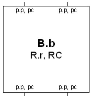
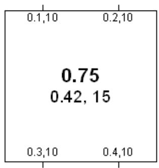
A template for and example of an STP Bridge.B.b is the Bridge Identifier (including the manageable priority componentB.). R.r and RC are the Root Identifier, Root Path Cost,and the Designated Bridge Identifier, for the Root Port. p.p, pc are the Port Identifier (with manageable priority p.) and the Port Path Cost for a Bridge Port.
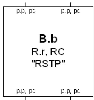
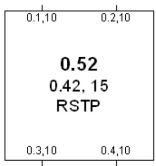
A template for and example of an RSTP Bridge.
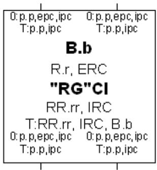
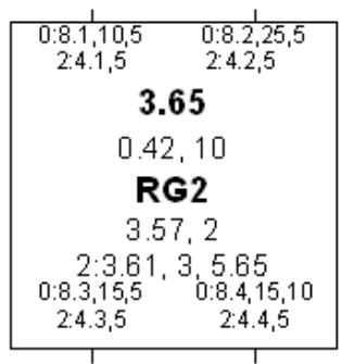
A template for and an example of an MSTP Bridge. B.b is the CIST Bridge Identifier. R.r, ERC,RR.rr are the ClST Root Identifier, External Root Path Cost, and Regional Root Identifier. CI identifies the Configuration Identifier for the Bridge RR.rr, IRC the ClST Regional Root Identifier and the Internal Root Path Cost T:RR.rr, IRC, B.b, is the Regional Root Identifier, Internal Root Path Cost IRC, and Bridge Identifier for the MSTI with MSTID T. O:p.p,epc, ipc are the ClST Port Identifier, External Port Path Cost, and Internal Port Path Cost for a Bridge Port T:p.p,ipc are the Port Identifiers and their Regional Costs for MSTI T. Any of the above information may be selectiv ely omitted if deemed irrelevant for the purposes of a diagram
A LAN
Connections between Bridges and LANs indicate the Port Role and Port State by means of their end point symbols, and in some examples, may show the tr ansmission of BPDUs from a Port onto a LAN by means of arrowheads, as shown in the following table.
<table><tr><td>Port Role</td><td>Port State</td><td>Legend</td></tr><tr><td>Designated& operEdge</td><td>DiscardingLearningForwarding</td><td>●●●●●●●●●●●●●●●●●●●●●●●●●●●●●●●●●●●●●●●●●●●●●●●●●●●●●●●●●●●●●●●●●●●●●●●●●●●●●●●●●●●●●●●●●●●●●●●●●●●●○○○○○○○○○○○○○○○○○○○○○○○○○○○○○○○○○○○○○○○○○○○○○○○○○○○○○○○○○○○○○○○○○○○○○○○○○○○○○○○○○○○○○○○○○○○○○○○○○○○○ ○○○○○○○○○○○○○○○○○○○○○○○○○○○○○○○○○○○○○○○○○○○○○○○○○○○○○○○○○○○○○○○○○○○○○○○○○○○○○○○○○○○○○○○○○○○○○○○○○○○○-</td></tr><tr><td>Root PortorMaster Port</td><td>DiscardingLearningForwarding</td><td>○○○○○○○○○○○○○○○○○○○○○○○○○○○○○○○○○○○○○○○○○○○○○○○○○○○○○○○○○○○○○○○○○○○○○○○○○○○○○○○○○○○○○○○○○○○○○○○○○○○</td></tr><tr><td>Alternate</td><td>DiscardingLearningForwarding</td><td>—+—+——</td></tr><tr><td>Backup</td><td>DiscardingLearningForwarding</td><td>—+—>1></td></tr><tr><td>Disabled</td><td>-</td><td>—</td></tr><tr><td colspan="3">Transmitted Bpdus</td></tr><tr><td colspan="2">DesignatedDesignated ProposalRootRoot Agreement</td><td>—→—→→—→→—→→→</td></tr></table>
NOTE—These diagrammatic conventions allow the representation of Alternate and Backup Ports that are in Learning or F orwarding states; this can happen as a transitory condition due to implementation dependent delays in switching off Learning andfor Forwarding on a Port that changes role from Designated or Root to AIternate or Backup.
Figure 13-1—Diagrammatic conventions for spanning tree topologies
Figure 13-2 shows a simple, redundantly connected, structured wiring configuration, with Bridges connected by point-to-point LANs A through N, and a possible spanning tree active topology of the same network. Bridge 111 has been selected as the Root (though one cannot tell simply by looking at the active topology which Bridge is the Root).
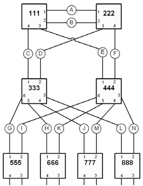
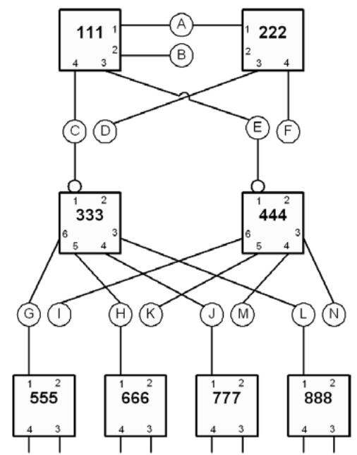
Figure 13-2—Physical topology and active topology
Figure 13-3 shows the Port Roles and Port States of each Bridge Port. It can be seen that Bridge 111 is the Root, as its Ports are all Designated Ports, each of the remaining Bridges have one Root Port.
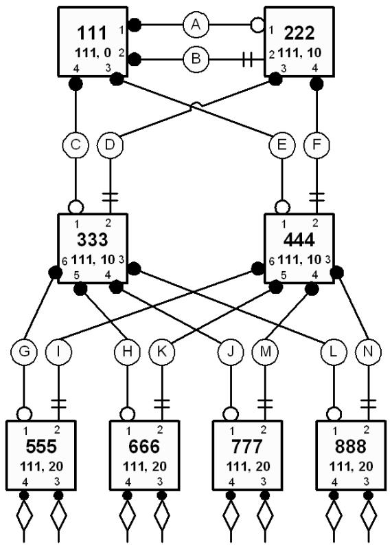
Figure 13-3—Port Roles and Port States
Figure 13-4 shows the result of connecting two of the ports of Bridge 888 to the same LAN. As port 4 of Bridge 888 has worse priority than port 3 and both offer the same Root Path Cost, port 4 will be assigned the Backup Port Role and will therefore be in the Discarding Port State. Should port 3 or its connection to LAN O fail, port 4 will be assigned the Designated Port Role and will transition to the Forwarding Port State.
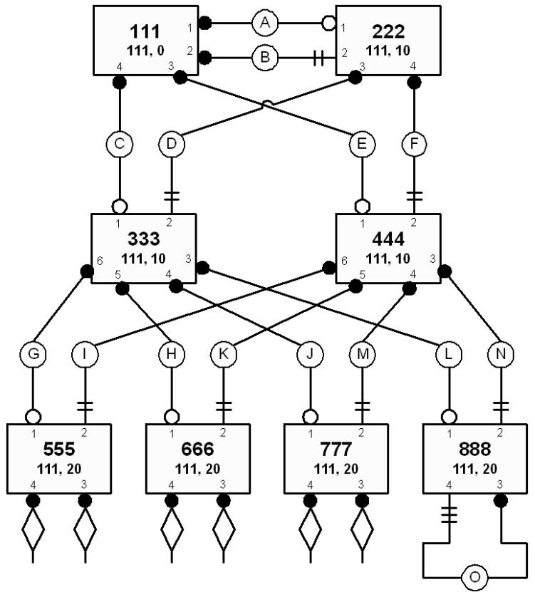
Figure 13-4—A Backup Port
Figure 13-5 shows a “ring” topology constructed from point-to-point links, as in some resilient backbone configurations. Bridge 111 is the Root, as in previous examples.
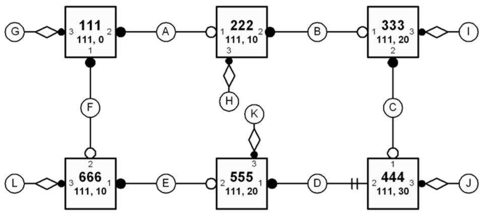
Figure 13-5—“Ring Backbone” example
13.5 MSTP overview
MSTP specifies the following:
a) An MST Configuration Identifier (MCID) (13.8) that allows each Bridge to advertise its assignment, to a specified MSTI or to the IST, of frames with any given VID.
b) A priority vector (13.9) that comprises Bridge identifier and path cost information for constructing a deterministic and manageable single spanning tree active topology, the CIST, that
1) Fully and simply connects all Bridges and LANs in a Bridged Network.
2) Permits the construction and identification of MST Regions of Bridges and LANs that are guaranteed fully connected by the Bridges and LANs within each region.
3) Ensures that paths within each MST Region are always preferred to paths outside the region.
c) An MSTI priority vector (13.9), comprising information for constructing a deterministic and independently manageable active topology for any given MSTI within each region.
d) Comparisons and calculations performed by each Bridge in support of the distributed spanning tree algorithm (13.10). These select a CIST priority vector for each Bridge Port, based on the priority vectors and MCIDs received from other Bridges and on an incremental Path Cost associated with each reception port. The resulting priority vectors are such that in a stable network:
1) One Bridge is selected to be the CIST Root of the Bridged Network as a whole.
2) A minimum cost path to the CIST Root is selected for each Bridge and LAN, thus preventing loops while ensuring full connectivity.
3) The one Bridge in each MST Region whose minimum cost path to the Root is not through another Bridge using the same MCID is identified as its region’s CIST Regional Root.
4) Conversely, each Bridge whose minimum cost path to the Root is through a Bridge using the same MCID is identified as being in the same region as that Bridge.
e) Priority vector comparisons and calculations performed by each Bridge for each MSTI (13.11). In a stable network:
1) One Bridge is independently selected for each MSTI to be the MSTI Regional Root.
2) A minimum cost path to the MSTI Regional Root that lies wholly within the region is selected for each Bridge and LAN.
f) CIST Port Roles (13.12) that identify the role in the CIST active topology played by each port on a Bridge:
1) The Root Port provides the minimum cost path from the Bridge to the CIST Root (if the Bridge is not the CIST Root) through the Regional Root (if the Bridge is not a Regional Root).
2) A Designated Port provides the least cost path from the attached LAN through the Bridge to the CIST Root.
3) Alternate or Backup Ports provide connectivity if other Bridges, Bridge Ports, or LANs fail or are removed.
g) MSTI and SPT Port Roles (13.12) that identify the role played by each port on a Bridge for each MSTI’s or SPT’s active topology within and at the boundaries of a region.
1) The Root Port provides the minimum cost path from the Bridge to the Regional Root (if the Bridge is not the Regional Root for the tree).
2) A Designated Port provides the least cost path from the attached LAN though the Bridge to the Regional Root.
3) A Master Port provides connectivity from the region to a CIST Root that lies outside the region. The Bridge Port that is the CIST Root Port for the CIST Regional Root is the Master Port for all MSTIs and SPTs.
4) Alternate or Backup Ports provide connectivity if other Bridges, Bridge Ports, or LANs fail or are removed.
h) State machines and state variables associated with each spanning tree (CIST, MSTI, or SPT), port, and port role, to select and change the Port State (8.4, 13.24) that controls the processing and forwarding of frames assigned to that tree by a MAC Relay Entity (8.3).
13.5.1 Example topologies
Figure 13-6 is an example Bridged Network, using the conventions of Figure 13-1, and chosen to illustrate MSTP calculations rather than as an example of a common or desirable physical topology.
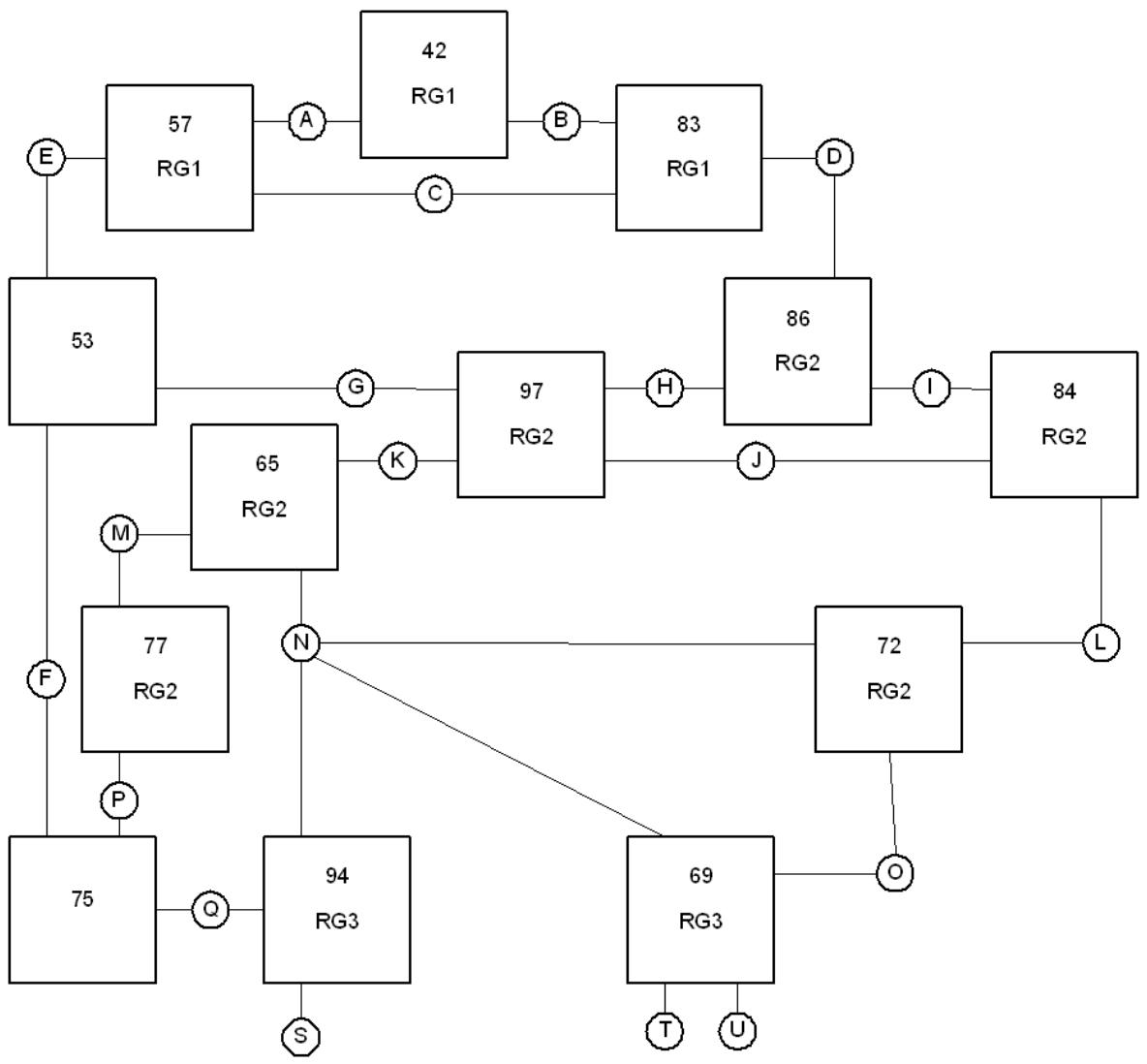
Figure 13-6—An MST Bridge network
Figure 13-7 is the same network showing Bridges and LANs with better CIST spanning tree priorities higher on the page, and including CIST priority vectors, port roles, and MST Regions. In this example:
a) Bridge 0.42 is the CIST Root because it has the best (numerically lowest) Bridge Identifier.
b) Bridges 0.57 and 2.83 are in the same MST Region (1) as 0.42, because they have the same MCID as the latter. Because they are in the same MST Region as the CIST Root, their External Root Path Cost is 0, and their CIST Regional Root is the CIST Root.
c) LANs A, B, C, and D are in Region 1 because their CIST Designated Bridge is a Region 1 MST Bridge, and no STP Bridges are attached to those LANs. LAN E is not in an MST Region (or in its own region—an equivalent view) because it is attached to Bridge 0.53, which is not an MST Bridge.
d) Bridges 0.77, 0.65, 0.97, 0.86, 3.84, and 3.72 are in the same MST Region (2) since they have the same MCID and are interconnected by LANs for which one of them is the CIST Designated Bridge.
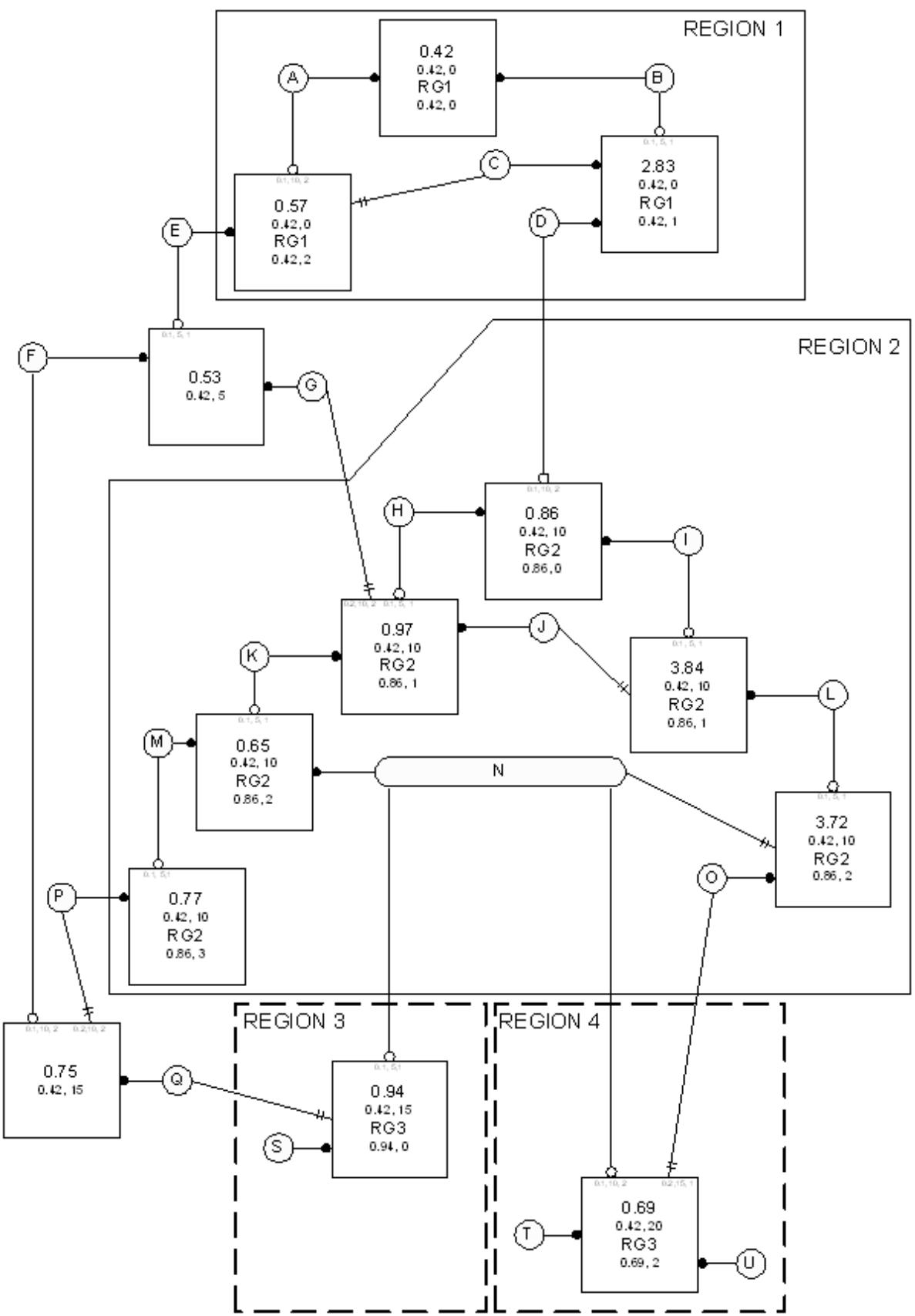
Figure 13-7—CIST Priority Vectors, Port Roles, and MST Regions
e) Bridge 0.86 is the CIST Regional Root for Region 2 because it is has the lowest External Root Path Cost through a Boundary Port.
f) LAN N is in Region 2 because its CIST Designated Bridge is in Region 2. Frames assigned to different MSTIDs may reach N from Bridge 0.86 (for example) by either Bridge 0.65 or Bridge 3.72, even though Bridges 0.94 and 0.69 with MCIDs that differ from those for Bridges in Region 2 are attached to this shared LAN.
g) Bridges 0.94 and 0.69 are in different regions, even though they have the same MCID, because the LAN that connects them (N) is in a different region.
Figure 13-8 shows a possible active topology of MSTI 2 within Region 2.
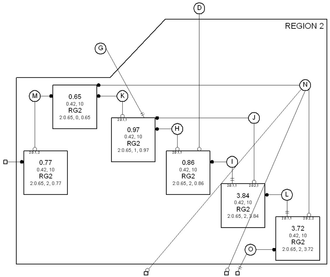
Connections to other MST regions
Figure 13-8—MSTI Active Topology in Region 2
h) Bridge 0.65 has been chosen as the MSTI Regional Root because it has the best (numerically the lowest) Bridge Identifier of all Bridges in the region for this MSTI.
i) The connectivity between the whole of Region 2 and Region 1 is provided through a single Bridge Port, the Master Port on Bridge 0.86. This port was selected for this role because it is the CIST Root Port on the CIST Regional Root for the region (see Figure 13-7).
j) The connectivity between the whole of Region 2 and LANs and Bridges outside the region for the MSTI is the same as that for the CIST. This connectivity is similar to that which might result by replacing the entire region by a single SST Bridge. The region has a single Root Port (this port is the Master Port for each MSTI) and a number of Designated Ports.
13.5.2 Relationship of MSTP to RSTP
MSTP is based on RSTP, extended so frames for different VLANs can follow different trees within regions.
a) The same fundamental spanning tree algorithm selects the CIST Root Bridge and Port Roles, but extended priority vector components are used within (13.9, 13.10) in each region. As a result each region resembles a single Bridge from the point of view of the CST as calculated by RSTP.
b) Each MSTI’s Regional Root Bridge and Port Roles are also computed using the same fundamental spanning tree algorithm with modified priority vector components (13.11).
c) Different Bridges may be selected as the Regional Root for different MSTIs by modifying the manageable priority component of the Bridge Identifier differently for the MSTIs.
d) MST Configuration Identification is not applicable to RSTP.
e) The Port Roles used by the CIST (Root, Designated, Alternate, Backup or Disabled Port) are the same as those of RSTP. The MSTIs use the additional port role Master Port. The Port States associated with each spanning tree and port are the same as those of RSTP.
f) The state variables for each Bridge Port for each tree and for the Bridge itself are those specified for RSTP as per port and per Bridge with a few exceptions, additions, and enhancements.
g) The performance parameters specified for RSTP apply to the CIST, with a few exceptions, additions, and enhancements. A simplified set of performance parameters apply to the MSTIs.
h) This standard specifies RSTP state machines and procedures as a subset of MSTP.
13.5.3 Modeling an MST or SPT Region as a single Bridge
The nominal replacement of an entire region by a single RST Bridge leads to little impact on the remainder of the Bridged Network. This design is intended to assist those familiar with RSTP to comprehend and verify MSTP, and to administer networks using MSTP. Treating the MST Regions as single Bridges provides the network administrator with a natural hierarchy. The internal management of MST Regions can be largely separated from the management of the active topology of the network as a whole.
The portion of the active topology of the network that connects any two Bridges in the same MST Region traverses only MST Bridges and LANs in that region and never Bridges of any kind outside the region; in other words, connectivity within the region is independent of external connectivity. This is because the protocol parameters that determine the active topology of the network as a whole, the Root Identifier and Root Path Cost (known in the MSTP specification as the CIST Root Identifier and CIST External Root Path Cost) are carried unchanged throughout and across the MST Region, so Bridges within the region will always prefer spanning tree information that has been propagated within the region to information that has exited the region and is attempting to reenter it.
NOTE 1—No LAN can be in more than one MST Region at a time, so two Bridges (0.11 and 0.22 say) that would otherwise be in the same region by virtue of having the same MST Configuration and of being directly connected by a LAN, may be in distinct regions if that is a shared LAN with other Bridges attached (having a different MST Configuration) and no other connectivity between 0.11 and 0.22 and lying wholly within their region is available. The region that the shared LAN belongs to may be dynamically determined. No such dynamic partitioning concerns arise with single Bridges. Obviously the sharing of LANs between administrative regions militates against the partitioning of concerns and should only be done following careful analysis.
The Port Path Cost (MSTP’s External Port Path Cost) is added to the Root Path Cost just once at the Root Port of the CIST Regional Root, the closest Bridge in the region to the Root Bridge of the entire network. The Message Age used by STP and RSTP is also only incremented at this port. If the CIST Root is within a region, it also acts as the Regional Root, and the Root Path Cost and Message Age advertised are zero, just as for a single Bridge.
Within an MST Region, each MSTI operates in much the same way as an independent instance of RSTP with dedicated Regional Root Identifier, Internal Root Path Cost, and Internal Port Path Cost parameters.
Moreover, the overall spanning tree (the CIST) includes a fragment (the IST) within each MST Region that can be viewed as operating in the same way as an MSTI with the Regional Root as its root.
NOTE 2—Since an MST Region behaves like a single Bridge and does not partition (except in the unusual configuration involving shared LANs noted above), it has a single Root Port in the CST active topology. Partitioning a network into two or more regions can therefore force nonoptimal blocking of Bridge Ports at the boundaries of those regions.
13.6 SPB overview
Clause 27 provides a comprehensive overview of SPT Bridges using SPBV and SPBM mode operation. This subclause (13.6) summarizes aspects of SPB operation that relate to the transmission and reception of BPDUs, and their role in providing interoperability with RSTP and MSTP, and in carrying the agreements that ensure that each SPT provides loop-free connectivity throughout an SPT Region. The details of agreements are considered in 13.17, the assignment of frames to SPTs in 8.4 and Clause 27, and protocols and procedures to allow plug-and-play generation of SPVIDs in Clause 28.
Considerations of backward and forward compatibility and interoperability figure largely in this clause (Clause 13) and to some extent these consideration revolve around the notion of MST or SPT Region, with each region capable of using different protocols or different configurations. These considerations should not be allowed to obscure the fact that the ideal network configuration (from the point of view of connectivity and bandwidth efficiency) comprises a single region, or possibly one core region with RST Bridges attached, and that separate regions are most likely to arise when continued connectivity is being provided by the CST as configuration changes are made to Bridges in the network. If an SPT Region is bounded by BEBs or LAN with no other Bridges attached, B-VLANs can be supported by SPBM mode, with frames assigned to SPTs using their MAC addresses, while other B-VLANs and S-VLANs can be supported by SPBV mode, with frames assigned to each SPT by SPVID. In both cases, however, SPTs are calculated in the same way and the effects on this clause (Clause 13) are limited to allowing loop mitigation (6.5.4.2) for unicast frames supported by SPBM mode as well as loop prevention (6.5.4.1). The need for unicast multicast congruence (Clause 3), the simplification possible by not introducing differences between SPBM mode unicast forwarding and the other uses of SPTs, and the need for source address lookup to support loop mitigation means that all shortest path bridged frames are assigned to an SPT rooted at the source Bridge and follow the standard bridging paradigm of multicast distribution with filtering, even when the frame has a single destination and the path to the destination is known through the use of routing protocol (ISIS-SPB).
NOTE—When loop mitigation is used for unicast frames, the Port State used to prevent loops (as expressed by the state machine variables forwarding and learning) need only apply to frames with group destination addresses.
SPT Bridges send and receive BPDUs in order to advertise their presence to, and recognize the presence of, other Bridges. The requirement for loop-free SPT connectivity also means that SPT Bridges have to communicate with their nearest neighbors, when calculations that follow the reception of ISIS-SPB messages have been completed rather than as a part of the IS-IS protocol itself. The agreements (13.17) that satisfy this requirement could be separated conceptually from other uses of BPDUs, but the opportunity to share common information elements, synchronization of neighbor state, and an overall reduction in the number of protocol frames sent make it convenient to use BPDUs to integrate its specification with the other protocol variables, procedures, and state machines in this clause (13.24–13.40). Agreement Protocol variables with exactly the same semantics are also carried in SPB Hello PDUs. The protocol handles duplicated and misordered agreement information, so that updated information can be received from SPB Hello PDUs or both SPB Hello PDUs and BPDUs.
SPT Bridges use the configuration and active topology management parameters (Bridge Identifiers, Port Path Costs) already required for the CIST. They also retain MSTP capabilities as a subset of their operation, though it is always possible to configure zero MSTIs.
13.7 Compatibility and interoperability
RSTP, MSTP, and the ISIS-SPB are designed to interoperate with each other and with STP. This subclause (13.7) reviews aspects of their design that are important to meeting that requirement. ISIS-SPB and SPT BPDUs include the functionality provided by MSTP and MST BPDUs, so the compatibility with RSTP and STP provided by the latter extends to SPB.
13.7.1 Designated Port selection
Correct operation of the spanning tree protocols requires that all Bridge Ports attached to any given LAN agree on a single CIST Designated Port after a short interval sufficient for any Bridge Port to receive a configuration message from that Designated Port.
A unique spanning tree priority (13.9) is required for each Bridge Port for STP, which has no other way of communicating port roles. Since port numbers on different Bridges are not guaranteed to be unique, this necessitates the inclusion of the transmitting Bridge’s Bridge Identifier in the STP BPDU. RSTP and MSTP’s Port Protocol Migration state machines (13.32) ensure that all Bridges attached to any LAN with an attached STP Bridge send and receive STP BPDUs exclusively.
NOTE 1—This behavior satisfies the requirement for unique, agreed Designated Port for LANs with attached STP Bridges, but means that an MST Region cannot completely emulate a single Bridge since the transmitted Designated Bridge Identifier can differ on Bridge Ports at the region’s boundary.
MSTP transmits and receives the Regional Root Identifier and not the Designated Bridge Identifier in the BPDU fields recognized by RSTP (14.4) to allow both the MST and the RST Bridges potentially connected to a single LAN to perform comparisons (13.9, 13.10) between all spanning tree priority vectors transmitted that yield a single conclusion about which RST Bridge or MST Region includes the Designated Port. MST and RST BPDUs convey the transmitting port’s CIST Port Role. This is checked on receipt by RSTP when receiving messages from a Designated Bridge, thus ensuring that an RST Bridge does not incorrectly identify one MST Bridge Port as being Designated rather than another, even while omitting the competing Bridge Ports’ Designated Bridge Identifiers from comparisons.
NOTE 2—This ability of MST Bridges to communicate the full set of MSTP information on shared LANs to which RST Bridges are attached avoids the need for the Port Protocol Migration machines to detect RST Bridges. Two or more MST and one or more RST Bridges may be connected to a shared LAN, with full MSTP operation. This includes the possibility of different MSTI Designated Ports (see 13.5.1).
13.7.2 Force Protocol Version
A Force Protocol Version parameter, controlled by management, permits emulation of aspects of the behavior of earlier versions of spanning tree protocol that are not strictly required for interoperability. The value of this parameter applies to all Bridge Ports.
a) STP BPDUs, rather than MST BPDUs, are transmitted if Force Protocol Version is 0.
b) RST BPDUs, rather than MST BPDUs, are transmitted if Force Protocol Version is 2. RST BPDUs omit the MCID and all MSTI Information.
c) All received BPDUs are treated as being from a different MST Region if Force Protocol Version is 0 or 2.
d) Rapid transitions are disabled if Force Protocol Version is 0. This allows MST Bridges to support applications and protocols that can be sensitive to the increased rates of frame duplication and misordering that can arise under some circumstances, as discussed in Annex K of IEEE Std 802.1D-2004 [B10].
e) The MSTP state machines allow full MSTP behavior if Force Protocol Version is 3 or more.
f) SPT BPDUs are transmitted if Force Protocol Version is 4 or more.
NOTE—Force Protocol Version does not support multiple spanning trees with rapid transitions disabled.
13.8 MST Configuration Identifier (MCID)
It is essential that all Bridges within an MST or SPT Region agree on the allocation of VIDs to spanning trees. If the allocation differs, frames for some VIDs may be duplicated or not delivered to some LANs at all. MST and SPT Bridges check that they are allocating VIDs to the same spanning trees as their neighbors in the same region by transmitting and receiving MCIDs in BPDUs. Each MCID includes a Configuration Digest that is compact but designed so that two matching identifiers have a very high probability of denoting the same allocation of VIDs to MSTIDs (Clause 3, 8.4) even if the identifiers are not explicitly managed. Suitable management practices for equipment deployment and for choosing Configuration Names and Revision Levels (see below) can guarantee that the identifiers will differ if the VID to tree allocation differs within a single administrative domain.
An MST or SPT Region comprises one or more MST or SPT Bridges with the same MCIDs, interconnected by and including LANs for which one of those Bridges is the Designated Bridge for the CIST and which have no Bridges attached that cannot receive and transmit RST BPDUs.
SPT BPDUs are a superset of MST BPDUs received and validated by MST Bridges as if they were MST BPDUs, so MSTP operates within an SPT Region just as if it were an MST Region. However, each shortest path VLAN is represented by a reserved MSTID value that is included in the Configuration Digest, so an SPT Region contains only SPT Bridges.
Each MCID contains the following components:
a) A Configuration Identifier Format Selector, the value 0 encoded in a fixed field of one octet to indicate the use of the following components as specified in this standard.
b) The Configuration Name, a variable length text string encoded within a fixed field of 32 octets, conforming to IETF RFC 2271’s definition of SnmpAdminString. If the Configuration Name is less than 32 characters, the text string should be terminated by the NUL character, with the remainder of the 32-octet field filled with NUL characters. Otherwise, the text string is encoded with no terminating NUL character.
c) The Revision Level, an unsigned integer encoded within a fixed field of 2 octets.
d) The Configuration Digest, a 16-octet signature of type HMAC-MD5 (see IETF RFC 2104) created from the MST Configuration Table (Clause 3, 8.9). To calculate the digest, the table is considered to contain 4096 consecutive two octet elements, where each element of the table (with the exception of the first and last) contains an MSTID value encoded as a binary number, with the first octet being most significant. The first element of the table contains the value 0, the second element the MSTID value corresponding to VID 1, the third element the MSTID value corresponding to VID 2, and so on, with the next to last element of the table containing the MSTID value corresponding to VID 4094, and the last element containing the value 0. The key used to generate the signature consists of the 16-octet string specified in Table 13-1.
Table 13-1—Configuration Digest Signature Key
<table><tr><td>Parameter</td><td>Mandatory value</td></tr><tr><td>Configuration Digest Signature Key</td><td>0x13AC06A62E47FD51F95D2BA243CD0346</td></tr></table>
NOTE—The formulation of the signature as described above does not imply that a separate VID to MSTID translation table has to be maintained by the implementation; rather that it should be possible for the implementation to derive the logical contents of such a table, and the signature value as specified above, from the other configuration information maintained by the implementation, as described in Clause 12.
The Configuration Digests of some VID to MSTID translations are shown in Table 13-2 to help verify implementations of this specification.
Table 13-2—Sample Configuration Digest Signature Keys
<table><tr><td>VID to MSTID translation</td><td>Configuration Digest</td></tr><tr><td>All VIDs map to the CIST, no VID mapped to any MSTI</td><td>0xAC36177F50283CD4B83821D8AB26DE62</td></tr><tr><td>All VIDs map to MSTID 1</td><td>0xE13A80F11ED0856ACD4EE3476941C73B</td></tr><tr><td>Every VID maps to the MSTID equal to (VID modulo 32) + 1</td><td>0x9D145C267DBE9FB5D893441BE3BA08CE</td></tr></table>
It is recommended that MST Bridge implementations provide an easily selectable or default configuration comprising a Configuration Name of the Bridge Address as a text string using the Hexadecimal Representation specified in IEEE Std 802, a Revision Level of 0, and a Configuration Digest representing a VID to MSTID translation table containing the value 0 for every element. Such a table represents the mapping of all VIDs to the CIST. Since the Bridge Address is unique to each Bridge, no two Bridges using this default configuration will be identified as belonging to the same region.
It is recommended that SPT Bridge implementations provide an easily selectable or default configuration comprising a Configuration Name of 'IEEE802.1 SPB Default', a Revision Level of 0, and a Configuration Digest representing an MST Configuration Table containing the value 0xFFD for VID 1, the value 0xFFF for VIDs 3600 to 3999, and the value 0 for every other element. Such a table represents the mapping of the default PVID to SPBV, an SPVID pool containing VIDs 3600 to 3999, and mapping all other VLANs to the CIST. This will allow SPT Bridges using the default configuration to form an SPT Region and operate the default VLAN in SPBV mode.
An Auxiliary MCID (14.4, 27.4.1, 28.12.2) is specified for SPB configuration and is conveyed in SPT BPDUs and SPB Hello PDUs. When a configuration change that cannot introduce loops is made, the previous MCID can be retained in the Auxiliary MCID, allowing a neighboring Bridge whose configuration has not yet been changed to maintain communication without creating a region boundary. This allows an operator to increase the number of SPVIDs available to SPBV mode or the number of Base VIDs for SPBV or SPBM modes (for example) without disrupting communication. To avoid creating a region boundary all the Bridges have to be configured so they are all using the same new MCID before any other change can be made.
13.9 Spanning tree priority vectors
Priority vectors permit concise specification of each protocol’s computation of the active topology, both in terms of the entire network and of the operation of individual Bridges in support of the distributed algorithm. MST, RST, and STP Bridges use spanning tree priority vector information in Configuration Messages (13.14), sent and received from neighboring Bridges, to assign Port Roles that determine each port’s participation in a fully and simply connected active topology based on one or more spanning trees. SPT Bridges use ISIS-SPB to disseminate the information necessary to calculate Port Roles throughout SPT Regions, and to perform those calculations, but also use this Configuration Message information for the CIST to ensure that neighboring Bridges agree on that active topology, and to receive the information if the CIST Root lies outside their SPT Region.
CIST priority vectors comprise the following components:
a) CIST Root Identifier, the Bridge Identifier of the CIST Root;
b) CIST External Root Path Cost, the inter-regional cost from the transmitting Bridge to the CIST Root;
c) CIST Regional Root Identifier, the Bridge Identifier of the single Bridge in a region whose CIST Root Port connects to a LAN in a different region, or of the CIST Root if that is within the region;
d) CIST Internal Root Path Cost, the cost to the CIST Regional Root;
e) CIST Designated Bridge Identifier, the Bridge Identifier for the transmitting Bridge for the CIST;
f) CIST Designated Port Identifier, the Port Identifier for the transmitting port for the CIST;
g) CIST Receiving Port Identifier (not conveyed in Configuration Messages, used as tie-breaker between otherwise equal priority vectors within a receiving Bridge).
The first two components of the CIST priority vector are significant throughout the network. The CIST External Root Path Cost transmitted by a Bridge is propagated along each path from the CIST Root, is added to at Bridge Ports that receive the priority vector from a Bridge in a different region, and thus accumulates costs at the Root Ports of Bridges that are not MST or SPT Bridges or are CIST Regional Roots and is constant within a region. The CIST Internal Root Path Cost is only significant and defined within a region. The last three components are used as locally significant tie breakers, not propagated within or between regions. The set of all CIST spanning tree priority vectors is thus totally ordered.
Since RSTP is not aware of regions, RSTP specifications also refer to the CIST Root Identifier and CIST External Root Path Cost simply as the Root Bridge Identifier and Root Path Cost, respectively, and omit the CIST Internal Root Path Cost (as does STP). MSTP encodes the CIST Regional Root Identifier in the BPDU field used by RSTP to convey the Designated Bridge Identifier (14.1.1), so an entire region appears to an RSTP capable Bridge as a single Bridge. RSTP’s CST use of CIST priority vectors can be conveniently specified by the use of the zero for the Internal Root Path Cost and the same values for both the Regional Root Identifier and Designated Bridge Identifier.
NOTE 1—The path to the CIST Root from a Bridge with a CIST Root Port within a region always goes to or through the CIST Regional Root.
NOTE 2—STP lacks the fields necessary for MST Bridges to communicate the Designated Bridge Identifier to resolve a potential priority vector tie, and MSTP BPDUs are not sent on a LAN to which an STP Bridge is attached.
Each MSTI priority vector comprises the following components for the particular MSTI in a given region:
h) MSTI Regional Root Identifier, the Bridge Identifier of the MSTI Regional Root;
i) MSTI Internal Root Path Cost, the path cost to the MSTI Regional Root;
j) MSTI Designated Bridge Identifier, the Bridge Identifier for the transmitting Bridge for this MSTI;
k) MSTI Designated Port Identifier, the Port Identifier for the transmitting port for this MSTI;
l) MSTI Receiving Port Identifier (not conveyed in Configuration Messages).
The set of priority vectors for a given MSTI is only defined within a region. Within each region they are totally and uniquely ordered. A CIST Root Identifier, CIST External Root Path Cost, and CIST Regional Root Identifier tuple defines the connection of the region to the external CST and is required to be associated with the source of the MSTI priority vector information when assessing the agreement of information for rapid transitions to forwarding, but plays no part in priority vector calculations.
As each Bridge and Bridge Port receives priority vector information from Bridges and ports closer to the Root, calculations and comparisons are made to decide which priority vectors to record, and what information to pass on. Decisions about a given port’s role are made by comparing the priority vector components that could be transmitted with that received by the port. For all components, a lesser numerical value is better, and earlier components in the above lists are more significant. As each Bridge Port receives information from ports closer to the Root, additions are made to one or more priority vector components to yield a worse priority vector for potential transmission through other ports of the same Bridge.
NOTE 3—The consistent use of lower numerical values to indicate better information is deliberate as the Designated Port that is closest to the Root Bridge, i.e., has a numerically lowest path cost component, is selected from among potential alternatives for any given LAN (13.9). Adopting the conventions that lower numerical values indicate better information, that where possible more significant priority components are encoded earlier in the octet sequence of a BPDU (14.1), and that earlier octets in the encoding of individual components are more significant (14.2) allow concatenated octets that compose a priority vector to be compared as if they were a multiple octet encoding of a single number, without regard to the boundaries between the encoded components. To reduce the confusion that naturally arises from having the lesser of two numerical values represent the better of the two, i.e., that chosen all other factors being equal, this clause uses the following consistent terminology. Relative numeric values are described as “least,” “lesser,” “equal,” and “greater,” and their comparisons as “less than,” “equal to,” or “greater than,” while relative spanning tree priorities are described as “best,” “better,” “the same,” “different,” and “worse” and their comparisons as “better than,” “the same as,” “different from,” and “worse than.” The operators “<” and “=” represent less than and equal to, respectively. The terms “superior” and “inferior” are used for comparisons that are not simply based on priority but include the fact that a priority vector can replace an earlier vector transmitted by the same Bridge Port. All of these terms are defined for priority vectors in terms of the numeric comparison of components below (13.10, 13.11).
NOTE 4—To ensure that the CIST and each MSTI’s view of the boundaries of each region remain in synchronization at all times, each BPDU carries priority vector information for the CIST as well as for MSTIs. Associating the CIST Root Identifier, External Path Cost, and Regional Root Identifier with the priority vector information for each MSTI does not therefore raise a requirement to transmit these components separately. A single bit per MSTI vector, the Agreement flag, satisfies the requirement to indicate that the vector beginning with the MSTI Regional Root Identifier for that specific MSTI has always been associated with the single CIST Root Identifier, etc. transmitted in the BPDU.
To allow the active topology to be managed for each tree through adjusting the relative priority of different Bridges and Bridge Ports for selection as the CIST Root, a CIST or MSTI Regional Root, Designated Bridge, or Designated Port, the priority component of the Bridge’s Bridge Identifier can be independently chosen for the CIST and for each MSTI. The priority component used by the CIST for its CIST Regional Root Identifier can also be chosen independently of that used for the CIST Root Identifier. Independent configuration of Port Path Cost and Port Priority values for the CIST and for each MSTI can also be used to control selection of the various roles for the CIST and for each MSTI.
In principle an SPT priority vector could be defined within an SPT Region, comprising a Regional Root Identifier and Internal Root Path Cost, and would reflect the construction of each SPT (lowest Internal Root Path Cost from each Bridge and LAN to the Regional Root). However, the set of such vectors cannot be totally ordered by the addition of purely local tie-breaker components: as each SPT Set has to be symmetric. Clause 28 specifies ISIS-SPB’s calculation of SPTs.
13.10 CIST Priority Vector calculations
The port priority vector is the priority vector held for the port when the reception of BPDUs and any pending update of information has been completed:
port priority vector = {RootID : ExtRootPathCost :
RRootID : IntRootPathCost :
DesignatedBridgeID : DesignatedPortID : RcvPortID}
The message priority vector is the priority vector conveyed in a received Configuration Message. For a Bridge with Bridge Identifier B receiving a Configuration Message on a port $P _ { B }$ from a Designated Port $P _ { D }$ on Bridge D claiming a CIST Root Identifier of $R _ { D _ { \mathrm { { \ell } } } }$ a CIST External Root Path Cost of $\mathrm { E R C } _ { D } ,$ a CIST Regional Root Identifier of $R R _ { D } ,$ , and a CIST Internal Root Path Cost of $H C _ { D } .$
message priority vector = $\{R_{D}:ERC_{D}:RR_{D}:IRC_{D}:D:P_{D}:P_{B}\}$
If B is not in the same region as D, the Internal Root Path Cost has no meaning to B and is set to 0.
NOTE 1—If a Configuration Message is received in an RST or STP BPDU, both the Regional Root Identifier and the Designated Bridge Identifier are decoded from the single BPDU field used for the Designated Bridge Parameter (the MST BPDU field in this position encodes the CIST Regional Root Identifier). An STP or RST Bridge is always treated by MSTP as being in an region of its own, so the Internal Root Path Cost is decoded as zero.
The received CIST message priority vector is the same as B’s port priority vector if
$$
\begin{array}{l} \left(R _ {D} = = R o o t I D\right) \& \& \left(E R C _ {D} = = E x t R o o t P a t h C o s t\right) \& \& \left(R R _ {D} = = R R o o t I D\right) \& \& \\ \left(I R C _ {D} = = I n t R o o t P a t h C o s t\right) \& \& (D = = D e s i g n a t e d B r i d g e I D) \& \& \left(P _ {D} = = D e s i g n a t e d P o r t I D\right) \\ \end{array}
$$
and is better if
$$
\begin{array}{l} \left(\left(R _ {D} < \text { RootID }\right)\right) | | \\ \left(\left(R _ {D} = = R o o t I D\right) \& \& \left(E R C _ {D} < E x t R o o t P a t h C o s t\right)\right) | | \\ \left(\left(R _ {D} = = R o o t I D\right) \& \& \left(E R C _ {D} = = E x t R o o t P a t h C o s t\right) \& \& \left(R R _ {D} < R R o o t I D\right)\right) \mid \\ \begin{array}{r l} \left(\left(R _ {D} = = R o o t I D\right) \& \& \left(E R C _ {D} = = E x t R o o t P a t h C o s t\right) \& \& \left(R R _ {D} = = R R o o t I D\right) \right. \\ & \& \& \left(I R C _ {D} < I n t R o o t P a t h C o s t)\right) | | \end{array} \\ \begin{array}{c} \left(\left(R _ {D} = = R o o t I D\right) \& \& \left(E R C _ {D} = = E x t R o o t P a t h C o s t\right) \& \& \left(R R _ {D} = = R R o o t I D\right) \right. \\ \& \& \left(I R C _ {D} = = I n t R o o t P a t h C o s t\right) \& \& (D < D e s i g n a t e d B r i d g e I D)) | | \end{array} \\ \begin{array}{r l} & ((R _ {D} = = R o o t I D) \& \& (E R C _ {D} = = E x t R o o t P a t h C o s t) \& \& (R R _ {D} = = R R o o t I D) \\ & \quad \& \& (I R C _ {D} = = I n t R o o t P a t h C o s t) \& \& (D = = D e s i g n a t e d B r i d g e I D) \\ & \quad \& \& (P _ {D} < D e s i g n a t e d P o r t I D)) \end{array} \\ \end{array}
$$
A received CIST message priority vector is superior to the port priority vector ${ \mathrm { i f } } ,$ and only if, the message priority vector is better than the port priority vector, or the Designated Bridge Identifier Bridge Address and Designated Port Identifier Port Number components are the same; in which case, the message has been transmitted from the same Designated Port as a previously received superior message, i.e., if
$$
\begin{array}{l} \begin{array}{c} (\{R _ {D}: E R C _ {D}: R R _ {D}: I R C _ {D}: D: P _ {D}: P _ {B} \} \\ \text { is better than } \end{array} \\ \{R o o t I D: E x t R o o t P a t h C o s t: R R o o t I D: I n t R o o t P a t h C o s t: \\ \text { DesignatedBridgeID }: \text { DesignatedPortID }: R c v P o r t I D \} \\ \begin{array}{r l} \mid & \left(\text {(D.BridgeAddress = = DesignatedBridgeID.BridgeAddress)} \& \& \right. \\ & \left(P _ {D}. \text {PortNumber = = DesignatedPortID.PortNumber})\right) \end{array} \\ \end{array}
$$
If the message priority vector received in a Configuration Message from a Designated Port is superior, it will replace the current port priority vector.
A root path priority vector for a port can be calculated from a port priority vector that contains information from a message priority vector, as follows:
If the port priority vector was received from a Bridge in a different region (13.29.8), the External Port Path Cost $E P C _ { P B }$ is added to the External Root Path Cost component, and the Regional Root Identifier is set to the value of the Bridge Identifier for the receiving Bridge. The Internal Root Path Cost component will have been set to zero on reception.
$$
\text { root path priority vector } = \{R _ {D}: E R C _ {D} + E P C _ {P B}: B: 0: D: P _ {D}: P _ {B} \}
$$
If the port priority vector was received from a Bridge in the same region (13.29.8), the Internal Port Path Cost $I P C _ { P B }$ is added to the Internal Root Path Cost component.
$$
\text { root path priority vector } = \{R _ {D}: E R C _ {D}: R R _ {D}: I R C _ {D} + I P C _ {P B}: D: P _ {D}: P _ {B} \}
$$
The Bridge priority vector for a Bridge B is the priority vector that would, with the Designated Port Identifier set equal to the transmitting Port Identifier, be used as the message priority vector in Configuration Messages transmitted on Bridge B’s Designated Ports if B was selected as the Root Bridge of the CIST.
$$
\text { Bridge priority vector } = \{B: 0: B: 0: B: 0: 0 \}
$$
The root priority vector for Bridge B is the best priority vector of the set of priority vectors comprising
a) The Bridge priority vector; plus
b) All root path priority vectors that
1) Have a Designated Bridge Identifier D that is not equal to B, and
2) Were received from a Bridge Port attached to a LAN that is not in the same SPT Region as B; plus
c) The root path priority vector calculated by ISIS-SPB (if SPB is enabled, and the attached LAN is within the Bridge’s SPT Region).
NOTE 2—The BPDUs sent and received by all Bridges attached to a LAN allow MST and SPT Bridges to determine whether each attached LAN is within their region independently of priority vector values. SPT Bridges take advantage of this fact by using ISIS-SPB to communicate the CST priority vector for each of SPT Region’s potential Master Ports throughout the region, at the same time as ISIS-SPB calculates the Port Roles for each SPT (see Clause 28).
If the Bridge priority vector is the best of this set of priority vectors, Bridge B has been selected as the CIST Root. Otherwise, the root priority vector will only be that calculated by ISIS-SPB if the Root Bridge or Regional Root is within the Bridge’s SPT Region.
The designated priority vector for a port Q on Bridge B is the root priority vector with B’s Bridge Identifier B substituted for the DesignatedBridgeID and Q’s Port Identifier $\mathcal { Q } _ { B }$ substituted for the DesignatedPortID and RcvPortID components. If Q is attached to a LAN that has one or more STP Bridges attached (as determined by the Port Protocol Migration state machine), B’s Bridge Identifier B is also substituted for the RRootID component.
If the designated priority vector is better than the port priority vector and the LAN attached to the port is not within the Bridge’s SPT Region (possibly because SPB is not enabled), the port will be the Designated Port for that LAN and the current port priority vector will be updated. If the attached LAN is within the Bridge’s SPT Region, then the Port Role is as calculated by ISIS-SPB and the port priority vector will be updated with the designated priority vector if and only if the port is a Designated Port. The message priority vector in Configuration Messages transmitted by a port always comprises the components of the designated priority vector for the port, even if the port is a Root Port.
13.11 MST Priority Vector calculations
The port priority vector for a given MSTI is the priority vector held for the port per MSTI when the reception of BPDUs and any pending update of information has been completed:
$$
\text { port priority vector } = \quad \begin{array}{l} \{\text { RRootID }: \text { IntRootPathCost }: \\ \text { DesignatedBridgeID }: \text { DesignatedPortID }: \text { RcvPortID } \} \end{array}
$$
The message priority vector for a given MSTI is the MSTI priority vector conveyed in a received Configuration Message. For a Bridge with Bridge Identifier B receiving a Configuration Message on a Regional Port $P _ { B }$ from a Designated Port $P _ { D }$ on Bridge D belonging to the same MST Region and claiming an Internal Root Path Cost of $I R C _ { D }$ :
$$
\text { message priority vector } = \{R R _ {D}: I R C _ {D}: D: P _ {D}: P _ {B} \}
$$
An MSTI message priority vector received from a Bridge not in the same MST Region is discarded.
An MSTI message priority vector received from a Bridge Port internal to the region is the same as the port priority vector if
$$
\begin{array}{r l} & ((R R _ {D} = = R R o o t I D) \& \& (I R C _ {D} = = I n t R o o t P a t h C o s t) \& \& (D = = D e s i g n a t e d B r i d g e I D) \\ & \quad \& \& (P _ {D} = = D e s i g n a t e d P o r t I D)) \end{array}
$$
and is better if
$$
\begin{array}{l} \left(\left(R R _ {D} < R R o o t I D\right)\right) \mid \mid \\ \left(\left(R R _ {D} = = R R o o t I D\right) \& \& \left(I R C _ {D} < I n t R o o t P a t h C o s t\right)\right) | | \\ \left(\left(R R _ {D} = = R R o o t I D\right) \& \& \left(I R C _ {D} = = I n t R o o t P a t h C o s t\right) \& \& (D < D e s i g n a t e d B r i d g e I D)\right) | | \\ \begin{array}{l} \left(\left(R R _ {D} = = R R o o t I D\right) \& \& \left(I R C _ {D} = = I n t R o o t P a t h C o s t\right) \& \& (D = = D e s i g n a t e d B r i d g e I D) \right. \\ \& \& \left(P _ {D} < D e s i g n a t e d P o r t I D)\right) \end{array} \\ \end{array}
$$
An MSTI message priority vector is superior to the port priority vector if, and only if, the message priority vector is better than the port priority vector, or the Designated Bridge Identifier Bridge Address and Designated Port Identifier Port Number components are the same; in which case, the message has been transmitted from the same Designated Port as a previously received superior message, i.e., if
$$
\begin{array}{l} \left(\left\{R R _ {D}: I R C _ {D}: D: P _ {D}: P _ {B} \right\} \right. \\ i s b e t t e r t h a n \\ \{R R o o t I D: I n t R o o t P a t h C o s t: D e s i g n a t e d B r i d g e I D: D e s i g n a t e d P o r t I D: R c v P o r t I D \} \\ ) \mid ((D. B r i d g e A d d r e s s = = D e s i g n a t e d B r i d g e I D. B r i d g e A d d r e s s) \& \& \\ (P _ {D}. \text { PortNumber } = = \text { DesignatedPortID.PortNumber })) \\ \end{array}
$$
If the message priority vector received in a Configuration Message from a Designated Port for the MSTI is superior, it will replace the current port priority vector.
NOTE 1—The agree flag (13.27.3) for the port and this MSTI will be cleared if the CIST Root Identifier, CIST External Root Path Cost, and CIST Regional Root Identifier in the received BPDU are not better than or the same as those for the CIST designated priority vector for the port following processing of the received BPDU.
A root path priority vector for a given MSTI can be calculated for a port that has received a port priority vector from a Bridge in the same region by adding the Internal Port Path Cost $I P C _ { P B }$ to the Internal Root Path Cost component.
$$
\text { root path priority vector } = \{R R _ {D}: I R C _ {D} + I P C _ {P B}: D: P _ {D}: P _ {B})
$$
NOTE 2—Internal Port Path Costs are independently manageable for each MSTI, as are the priority components of the Bridge and Port Identifiers. The ability to independently manage the topology of each MSTI without transmitting individual Port Path Costs is a key reason for retaining the use of a Distance Vector protocol for constructing MSTIs. A simple link state protocol requires transmission (or a priori sharing) of all Port Costs for all links.
The Bridge priority vector for a Bridge B for a given MSTI is the priority vector that would, with the Designated Port Identifier set equal to the transmitting Port Identifier, be used as the message priority vector in Configuration Messages transmitted on Bridge B’s Designated Ports if B was selected as the Root Bridge of a given tree.
$$
\text { Bridge priority vector } = \{B: 0: B: 0 \}
$$
The root priority vector for Bridge B is the best priority vector of the set of priority vectors comprising the Bridge priority vector plus all root path priority vectors whose Designated Bridge Identifier D is not equal to
B. If the Bridge priority vector is the best of this set of priority vectors, Bridge B has been selected as the Root of the tree.
The designated priority vector for a port Q on Bridge B is the root priority vector with B’s Bridge Identifier B substituted for the DesignatedBridgeID and $\varrho \mathrm { s }$ Port Identifier $\mathcal { Q } _ { B }$ substituted for the DesignatedPortID and RcvPortID components.
If the designated priority vector is better than the port priority vector, the port will be the Designated Port for the attached LAN and the current port priority vector will be updated. The message priority vector in MSTP BPDUs transmitted by a port always comprises the components of the designated priority vector of the port, even if the port is a Root Port.
Figure 13-8 shows the priority vectors and the active topology calculated for an MSTI in a region of the example network of Figure 13-6.
13.12 Port Role assignments
Each Bridge assigns CIST Port Roles (when new information becomes available as specified in this subclause, 13.12) before assigning MSTI or SPT Port Roles. The calculations specified in 13.10 are used to assign a role to each Bridge Port that is enabled as follows:
a) If the Bridge is not the CIST Root, the source of the root priority vector is the Root Port.
b) Each port whose port priority vector is the designated priority vector is a Designated Port.
c) Each port, other than the Root Port, with a port priority vector received from another Bridge is a Alternate Port.
d) Each port with a port priority vector received from another port on this Bridge is a Backup Port.
If the port is not enabled, i.e., its MAC_Operational status is FALSE or its Administrative Bridge Port state is Disabled (8.4), it is assigned the Disabled Port role for the CIST, all MSTIs, and all SPTs, to identify it as having no part in the operation of any of the spanning trees or the active topology of the network.
If the Bridge is an MST or SPT Bridge, the calculations specified in 13.11 are used to assign a role to each enabled Bridge Port for each MSTI as follows:
e) If the port is the CIST Root Port and the CIST port priority vector was received from a Bridge in another MST or SPT Region, the port is the Master Port.
f) If the Bridge is not the MSTI Regional Root, the port that is the source of the MSTI root priority vector is the Root Port.
g) Each port whose port priority vector is the designated priority vector derived from the root priority vector is a Designated Port.
h) Each port, other than the Master Port or the Root Port, with a port priority vector received from another Bridge or a CIST port priority vector from a Bridge in another region, is an Alternate Port.
i) Each port that has a port priority vector that has been received from another port on this Bridge is a Backup Port.
Independently of priority vector values and active topology calculations, each SPT Bridge Port determines from received BPDUs whether all the Bridges attached to its LAN are in the same SPT Region. If not, the port is a Boundary Port, and its role for each SPT is determined by its CIST Port Role as follows:
j) If the port is the CIST Root Port, the port is the Master Port for all SPTs.
k) If the port is not the CIST Root Port, the port’s role is the same as that for the CIST.
By excluding Boundary Ports from the physical topology used to calculate SPTs, and adopting CIST connectivity at those ports, ISIS-SPB ensures that the use of SPVIDs (see Clause 27) is not required on shared media LANs attached to Bridges in other regions.
SPT Bridges use ISIS-SPB to assign Port Roles for each SPT to non-Boundary Ports as follows:
l) If the Bridge is not the SPT Root Bridge, the port that ISIS-SPB has calculated as providing the path for frames assigned to the SPT and forwarded to the Bridge from that SPT Root is the Root Port.
m) Each port, other than the Root Port, that ISIS-SPB has calculated as providing a path for frames forwarded from the SPT Root to the attached LAN is a Designated Port.
n) Each port that is attached to the same LAN as another port on that same Bridge that is a Designated Port for the SPT, is a Backup Port.
o) Each port not assigned a Root, Designated, or Backup Port role is an Alternate Port.
13.13 Stable connectivity
This subclause provides an analysis to show that RSTP, MSTP, and ISIS-SPB meet the goal of providing full and simple connectivity for frames assigned to any given VID in a stable network, i.e., where the physical topology has remained constant for long enough that the spanning tree information communicated and processed by Bridges is not changing.
NOTE 1—The FDB can be configured to prevent connectivity, in particular this analysis assumes that every Bridge Port is a member of every VID’s Member Set (8.8.10). Spanning tree protocol controls can also be used to prevent new connectivity (to allow for upgrades), or to disallow certain topologies (restricting the location of the CIST Root, for example). This analysis assumes that those controls are not being used, that all the Bridges are using conformant protocol implementations and that the LANs are providing omnidirectional connectivity.
Every LAN provides connectivity for all frames between all attached Bridge Ports. Every Bridge provides connectivity between and only between its CIST Root and Designated Ports for frames assigned to the CIST; between the Root, Designated, and Master Ports for a given MSTI for frames assigned to that MSTI; and between Root and Designated Ports for a given SPT for frames assigned to that SPT. Any given Bridge does not assign frames to more than one tree and has one Root Port per tree, unless it is the Root of that tree.
Every LAN has one and only one CIST Designated Port, and every Bridge apart from the CIST Root has one and only one CIST Root Port. The CIST spanning tree priority vector of the Designated Port attached to the LAN that is connected to a Bridge’s Root Port is better than of any Designated Port of that Bridge. The CIST thus connects all Bridges and LANs (is “spanning”) and loop-free (is a “tree”).
Each MST or SPT Region is bounded by CST Root and Alternate Ports. At the CST Root Ports connectivity for frames assigned to MSTIs or SPTs within the connected regions is the same as that for the CIST. Every region apart from that containing the CIST Root has a single CST Root Port, identified as the Master Port for each MSTI. The CIST spanning tree priority vector of the LAN attached to the region’s CST Root Port is better than that of any CST Designated Port of a Bridge in the region attached to a LAN also attached to the CST Root Port of another region. The CST thus provides loop-free connectivity between all regions.
NOTE 2—The term “Common Spanning Tree (CST)” refers to the CIST connectivity between regions, and the term “Internal Spanning Tree (IST)” to the CIST connectivity within each region. An RST Bridge and the LANs for which it is the Designated Bridge are conveniently considered as forming an MST region of limited extent.
Within each region each frame is consistently assigned to the CIST, an MSTI, or an SPT, and each of these spanning trees provides full loop-free connectivity to each of the Bridges within the region, just as the CIST does for the network as a whole, including connectivity between the CST Root Port (Master Port) and the CST Designated Ports. Since each Bridge or LAN is in one and only one region, and it has already been shown that loop-free connectivity is provided between regions, loop-free connectivity is thus provided between all the Bridges and LANs in the network.
Figure 13-9 illustrates the above connectivity with the simple example of Region 1 from the example network of Figure 13-6 and Figure 13-8. Bridge 0.42 has been selected as the CIST Root and Regional Root, Bridge 0.57 as the Regional Root for MSTI 1, and Bridge 2.83 for MSTI 2 by management of the per MSTI Bridge Identifier priority component. The potential loop through the three Bridges in the region is blocked at different Bridge Ports for the CIST, and each MSTI, but the connectivity across the region and from each LAN and Bridge in the region through the boundaries of the region is the same in all cases.
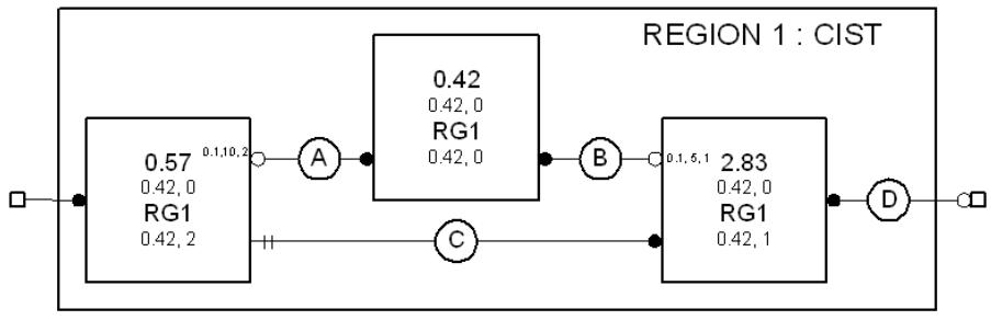
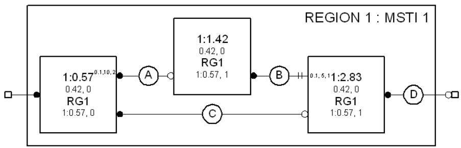
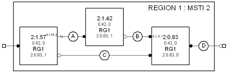
Figure 13-9—CIST and MSTI active topologies in Region 1 of the example network
13.14 Communicating spanning tree information
A Spanning Tree Protocol Entity transmits and receives group addressed BPDUs (Clause 14, 8.13.4) through each of its Bridge Ports to communicate with the Spanning Tree Protocol Entities of the other Bridges attached to the same LAN. The group address used is one of a small number of addresses that identify frames that are not directly forwarded by Bridges (8.6.3), but the information in the BPDU can be used by a Bridge in calculating its own BPDUs to transmit and can stimulate that transmission.
BPDUs are used to convey the following:
a) Configuration Messages
b) Topology Change Notification (TCN) Messages
c) MCIDs
d) Agreement parameters to support SPB
Designated Ports also transmit BPDUs at intervals to guard against loss and to assist in the detection of failed components (LANs, Bridges, or Bridge Ports), so all messages are designed to be idempotent.
A Configuration Message for the CIST can be encoded in an STP Configuration BPDU, an RST BPDU, an MST BPDU, or an SPT BPDU (14.1, 14.5). A TCN Message for the CIST can be encoded in an STP Topology Change Notification BPDU (14.2), or an RST, MST, or SPT BPDU with the TC flag set. Configuration and TCN Messages for the CIST and for all MSTIs in an MST Region are encoded in a single MST or SPT BPDU, as is the MCID. No more than 64 MSTI Configuration Messages shall be encoded in an MST BPDU, and no more than 64 MSTIs shall be supported by an MST Bridge.
When SPB is enabled, ISIS-SPB is used to communicate CST priority vectors, IST topology information, and CST topology change information to and from the other Bridges in the SPT Region and to calculate IST and SPT Port Roles and designated priority vectors. However, the full CIST priority information is still conveyed in SPT BPDUs, partly to encode agreement information for the IST, but principally to support interoperability at the boundaries of each region without having to assess whether the transmitting port is at a boundary before deciding what to encode in each BPDU.
Configuration and Topology Change Notification BPDUs are distinguished from each other and from RST and MST BPDUs by their BPDU Type (Clause 14). RST and MST BPDUs share the same BPDU Type and are distinguished by their version identifiers.
Bridges implementing STP (Clause 8 of IEEE Std 802.1D, 1998 Edition [B9]) transmit and decode Configuration and Topology Change Notification BPDUs, and ignore RST and MST BPDUs on receipt. This ensures that connection of a Bridge Port of such a Bridge to a LAN that is also attached to a Bridge implementing RSTP or MSTP is detected, as transmission of RSTP or MSTP BPDUs does not suppress regular transmissions by the STP Bridge. This functionality is provided by the Port Protocol Migration state machine for RSTP (13.32). The Port Protocol Migration state machines select the BPDU types used to encode spanning tree messages so that all Bridges attached to the same LAN participate in a spanning tree protocol, while maximizing the available functionality. If one or more attached Bridges only implement STP, only Configuration and Topology Change Notification BPDUs will be used and the functionality provided by the protocol will be constrained.
13.15 Changing spanning tree information
Addition, removal, failure, or management of the parameters of Bridges and LAN connectivity can change spanning tree information and require Port Role changes in all or part of the network (for the CIST) or all or part of an MST or SPT Region (for an MSTI or SPT Set). A CIST or MSTI configuration message received in a BPDU is considered superior to, and will replace, that recorded in the reception Port’s port priority vector if its message priority vector is better, or if it was transmitted by the same Designated Bridge and Designated Port and the message priority vector, timer, or hop count information differ from those recorded.
RSTP and MSTP propagate new information rapidly from Bridge to Bridge, superseding prior information and stimulating further transmissions until it reaches either Designated Ports that have already received the new information through redundant paths in the network or the leaves of the spanning tree, as defined by the new configuration. Configuration Message transmissions will then once more occur at regular intervals from ports selected as Designated Ports.
To ensure that old information does not endlessly circulate through redundant paths in the network, preventing the effective propagation of the new information, MSTP associates a hop count with the information for each spanning tree. The hop count is assigned by the CIST Regional Root or the MSTI Regional Root and decremented by each reception Port. Received information is discarded and the port made a Designated Port if the hop count reaches zero.
RSTP and MSTP’s CST processing do not use an explicit hop count (for reasons of STP compatibility), but detect circulating aged information by treating the BPDU Message Age parameter as an incrementing hop count with Max Age as its maximum value. MSTP increments Message Age for information received at the boundary of an MST Region, discarding the information if necessary.
If a Bridge Port’s MAC_Operational parameter becomes FALSE, the port becomes a Disabled Port and received information is discarded. Spanning tree information for the tree can be recomputed, the Bridge’s Port Roles changed, and new spanning tree information transmitted if necessary. Not all component failure conditions can be detected in this way, so each Designated Port transmits BPDUs at regular intervals and a reception Port will discard information and become a Designated Port if two transmissions are missed.
NOTE—Use of a separate hop count and message loss detection timer provides superior reconfiguration performance compared with the original use of Message Age and Max Age by STP. Connectivity loss detection is not compromised by the need to allow for the overall diameter of the network, nor does the time allowed extend the number of hops permitted to aged recirculating information. Management calculation of the necessary parameters for custom topologies is also facilitated, as no allowance needs to be made for relative timer jitter and accuracy in different Bridges.
ISIS-SPB communicates CST, IST, and SPT information throughout an SPT Region using link state procedures specified in Clause 28. In addition to the normal hop-by-hop distribution of this information, which is essential to guarantee its dissemination, each link state PDU (LSP) is also broadcast on the SPT rooted at the originating Bridge, so new information can reach Bridges in the region with the same delay as data.
13.16 Changing Port States with RSTP or MSTP
The Port State for the CIST and each MSTI for each Bridge Port is controlled by state machines whose goal is to maximize connectivity without introducing temporary loops in each of these active topologies. Root Ports, Master Ports, and Designated Ports are transitioned to the Forwarding Port State, and Alternate Ports and Backup Ports to the Discarding Port State, as rapidly as possible. Transitions to the Discarding Port State can be simply effected without the risk of data loops. This subclause (13.16) describes the conditions that RSTP and MSTP use to transition a Port State for a given spanning tree to Forwarding.
Starting with the assumption that any connected fragment of a network is composed of Bridges, Bridge Ports, and connected LANs that form a subtree of a spanning tree, ports with Root Port, Master Port, or Designated Port roles are transitioned using conditions that ensure that the newly enlarged fragment continues to form either a subtree or the whole of the spanning tree. Since the conditions are used every time a fragment is enlarged, it is possible to trace the growth of a fragment from a single Bridge—a consistent, if small, subtree of a spanning tree—to any sized fragment, thus justifying the initial assumption.
Port States in two subtrees, each bounded by ports that are not forwarding or are attached to LANs not attached to any other Bridge, can be made consistent by waiting for any changes in the priority vector information used to assign Port Roles to reach all Bridges in the network, thus ensuring that the subtrees are not, and are not about to be, joined by other Forwarding Ports. However, it can be shown that a newly selected Root Port can forward frames as soon as prior recent root ports on the same Bridge cease to do so, without further communication from other Bridges. Rapid transitions of Designated Ports and Master Ports do require an explicit Agreement from the Bridges in the subtrees to be connected. The Agreement mechanism is described, together with a Proposal mechanism that forces satisfaction of the conditions if they have not already been met by blocking Designated Ports connecting lower subtrees that are not yet in agreement. The same Agreement mechanism is then used to transition the newly blocked ports back to forwarding, advancing any temporary cut in the active topology toward the edge of the network.
13.16.1 Subtree connectivity and priority vectors
Any given Bridge B, the LANs connected through its Forwarding Designated Ports, the further Bridges connected to those LANs through their Root Ports, the LANs connected to their Forwarding Designated Ports, and so on, recursively, constitute a subtree $S _ { B } .$ . Any LAN L that is part of $S _ { B }$ will be connected to B through a Forwarding Designated Port $P _ { C L }$ on a Bridge C also in $S _ { B } . L$ cannot be directly connected to any port $P _ { B }$ on Bridge B unless B and C are one and the same, since the message priority vector for $P _ { B }$ is better than that of any port of any other Bridge in $\mathrm { S _ { B } , }$ and prior to Forwarding $P _ { C L }$ will have advertised its spanning port priority vector for long enough for it to receive any better message priority vector (within the design probabilities of protocol failure due to repeated BPDU loss) or will have engaged in an explicit confirmed exchange (see below) with all other Bridge Ports attached to that LAN.
NOTE—The analysis for the distance vector-based RSTP and MSTP differs from that for the link state-based ISIS-SPB (see 13.17). In the latter C’s priority vector can become better than B’s while C remains in $S _ { B } ,$ without B being aware of the improvement first.
13.16.2 Root Port transition to Forwarding
It follows from the above that B’s Root Port can be transitioned to Forwarding immediately whether it is attached to a LAN in $S _ { B }$ or in the rest of the network, provided that all prior recent Root Ports on B (that might be similarly arbitrarily attached) have been transitioned to Discarding and the Root Port was not a Backup Port recently (B and C the same as above).
13.16.3 Designated Port transition to Forwarding
On any given Bridge A, the Designated Port $P _ { A M }$ connected to a LAN M can be transitioned to Forwarding provided that the message priority advertised by the Designated Port $P _ { C L }$ on any LAN L in any subtree $S _ { M I } .$ , $S _ { M 2 } ,$ etc. connected to M is worse than that advertised by $P _ { A M } { \mathrm { i } }$ that any Bridge D attached to L has agreed that $P _ { C L }$ is the Designated Port; and that only the Root Port and Designated Ports on D are Forwarding. A sufficient condition for $P _ { A M }$ to transition to Forwarding is that M is a point-to-point link attached to the Root Port $P _ { B M }$ of a Bridge B, that the port priority of $P _ { B M }$ is the same as or worse than that of $P _ { A M } ,$ and any port $P _ { B N }$ on B is Discarding or similarly attached to a Bridge C. $P _ { B M }$ signals this condition to $P _ { A M }$ by setting the Agreement flag in a Configuration Message carrying $P _ { B M } \mathrm { ^ { 2 } s }$ designated priority and Port Role.
NOTE 1—RSTP and MSTP use adminPointToPointMAC and operPointToPointMAC (IEEE Std 802.1AC) to allow the point-to-point status of LANs to be managed and used by the Port Role Transition state machines for Designated Ports. A newly selected Root Port can be transitioned to Forwarding rapidly, even if attached to a shared media LAN.
Figure 13-10 illustrates the generation of an Agreement at a Bridge’s Root Port from an Agreement received or a Port State of Discarding at each of its Designated Ports, and a Port State of Discarding at each of its Alternate and Backup Ports. A Bridge receiving a Proposal transitions any Designated Port not already synchronized to Discarding so it can send the Agreement, and that port solicits an Agreement by sending a Proposal in its turn.
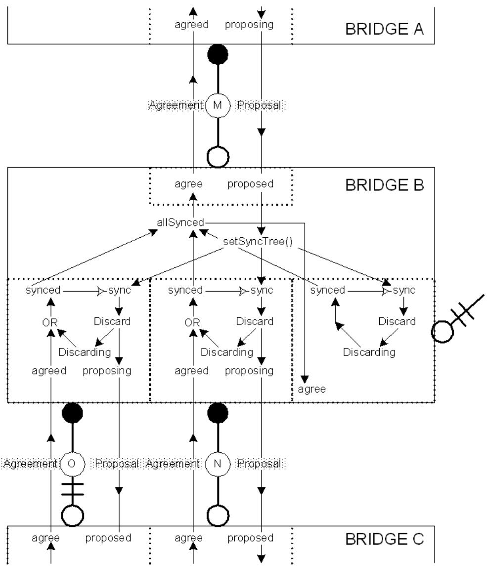
Figure 13-10—Agreements and Proposals
NOTE 2—Agreements can be generated without prior receipt of a Proposal as soon as the necessary conditions are met. Subsequent receipt of a Proposal serves to elicit a further Agreement. If all other ports have already been synchronized (allSynced in Figure 13-10) and the Proposal’s priority vector does not convey worse information, synchronization is maintained and there is no need to transition Designated Ports to Discarding once more, or to transmit further Proposals.
13.16.4 Master Port transition to Forwarding
While the connectivity of the CIST from the CIST Regional Root through an MST Region to the rest of the CST comprises a subtree rooted in the CIST Regional Root, the connectivity of the MSTI from the Master Port includes both a subtree below the CIST Regional Root and a subtree rooted in the MSTI Regional Root and connected to the CIST Regional Root by an MSTI Root Port. In the example network of Figure 13-6, this latter subtree continues CST connectivity, from the Master Port on Bridge 86 through to LAN N, for frames allocated to the MSTI within Region 2 (see Figure 13-11). In general either MSTI subtree could be providing CST connectivity through a prior Master Port: the connectivity of both subtrees has to agree with the new CIST Regional Root, before a new Master Port transitions to Forwarding.
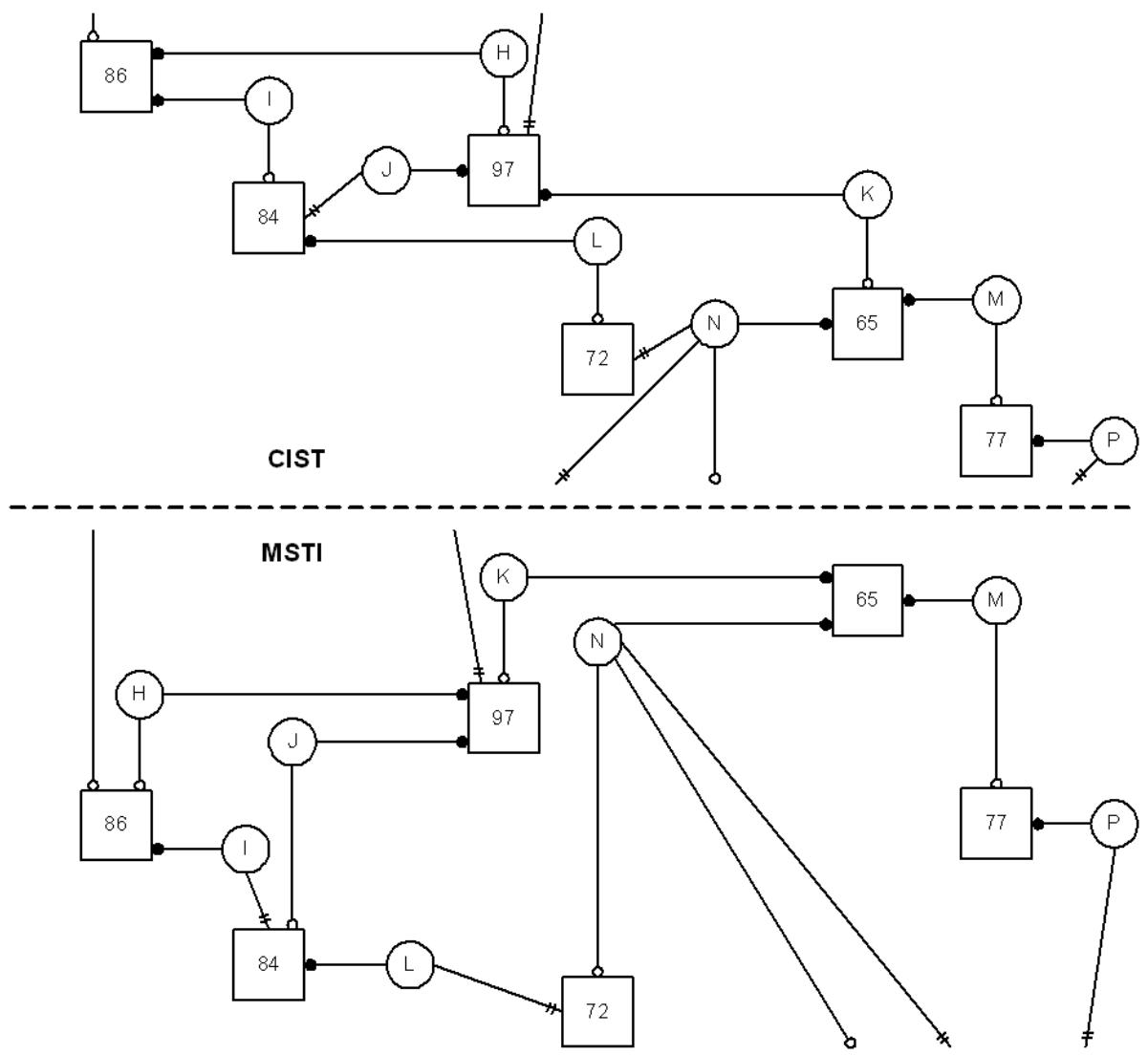
Figure 13-11—CIST and MSTI Active Topologies in Region 2 of Figure 13-6
NOTE 1—The physical layout shown in the two halves of Figure 13-11 differs in order to reflect the different priorities and logical topologies for the two spanning tree instances. The layout convention is that Designated Ports are shown as horizontal lines, Root Ports as vertical lines, and Alternate Ports as diagonal lines.
Figure 13-12 illustrates the extension of the Agreement mechanism to signal from Designated Ports to Root Ports as well as vice versa. To ensure that an MSTI does not connect alternate Master Ports, an Agreement is only recognized at an MSTI Port when the associated CIST Regional Root information matches that selected by the reception Port. Proposals, eliciting Agreements, necessarily flow from Designated Ports to Root Ports with the propagation of spanning tree information, so a new CIST Regional Root cannot transmit a Proposal directly on its MSTI Root Ports. However, updating a CIST Designated Port’s port priority vector with a new Regional Root Identifier forces the port to discard frames for all MSTIs, thus initiating the Proposal from the first Bridge nearer the MSTI Regional Root that learns of the new Regional Root.
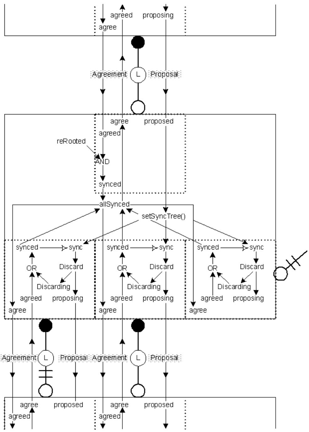
Figure 13-12—Enhanced Agreements
When an Agreement AMR is sent by a Root Port $P _ { M R }$ on a Regional Root M, it attests that the CIST Root Identifier and External Root Path Cost components of the message priority advertised on all LANs connected to the CIST by $P _ { M R }$ through M are the same as or worse than those accompanying $A _ { M R } .$ The connectivity provided by each MSTI can be independent of that provided by the CIST within the MST Region and can therefore connect $P _ { M R }$ and one or more CIST Root Ports external to but attached at the boundary of the region even as CIST connectivity within the region is interrupted in order to satisfy the conditions for generating $\mathbf { A } _ { \mathrm { M R } } .$ . The Agreement cannot therefore be generated unless all MSTI subtrees as well as the CIST subtree internal to the region are in Agreement. To ensure that an MSTI does not connect to a CIST subtree external to the region that does not meet the constraints on the CST priority vector components, an Agreement received at an MSTI Designated Port from a Bridge Port not internal to the region is only recognized if the CIST Root Identifier and External Root Path Cost of the CIST root priority vector selected by the transmitting Bridge Port are equal to or worse than those selected by the receiver. Updating of a CIST Designated Port’s port priority vector with a worse CIST Root Identifier and External Root Path Cost forces the port to discard frames for all MSTIs, thus initiating a Proposal that will elicit agreement.
NOTE 2—MSTI Designated Ports are prompted to discard frames, as required above, as follows. The CIST Port Information state machine sets sync for all MSTIs on a transition into the UPDATE state if updating the port priority with the designated priority changes the Regional Root Identifier or replaces the CIST Root Identifier or External Path Cost with a worse tuple. The MSTI’s Port Role Transition machine acts on the sync, instructing the port to discard frames, and setting synced and cancelling sync when the port is discarding or an agreement is received.
NOTE 3—A “cut” in an MSTI can be transferred to the CST, either at a Designated Port attached to the same LAN as an STP Bridge or at the Root Port of a Bridge in an adjacent region. If the CST priority components have already been synced, as is likely if the original cut was caused by changes in physical topology within the region, the cut will terminate there. Otherwise, the transferred cut precedes a cut in the CIST, and the synced port may terminate the latter. In that way, cuts in the CST will proceed through an MST Region by the quickest tree that will carry them.
NOTE 4—In the important topology where the CIST Root Bridge is within an MST Region, cuts are not transferred from the region’s IST to any MSTI. CIST cuts propagating in the region will not disrupt MSTI connectivity.
13.17 Changing Port States with SPB
While the link state routing protocols are less likely to create temporary loops than distance vector-based protocols, loops are still possible if (for example) two (or more) links fail about the same time. Any potential loop is a serious problem for bridged networks, as a frame that is multicast or whose destination has not been learned and is traveling around a loop is copied to each of the connected subtrees on every circuit, consuming bandwidth throughout the network. Each SPT Bridge Port uses SPT BPDUs and/or SPB Hello PDUs (28.2) to ensure that additions to each active topology do not occur unless there is sufficient agreement between neighboring Bridges (with some ports temporarily transitioned to Discarding if necessary) to ensure that a temporary loop will not be created.
Like RSTP and MSTP, agreements (see 13.16, Figure 13-12) are used to ensure that ports that transition to forwarding do not create loops. However, IS-IS distributes information in parallel with computation, rather than computing a new active topology hop-by-hop as priority vector information is passed from the Root Bridge to members of a potential subtree. Moreover the distribution path is not restricted to the potential subtree. Arbitrary distribution and parallel computation means that different Bridges can complete topology calculations at quite different times, with two major consequences as follows.
First, each Bridge is not necessarily aware of priority vector changes passed to any subtree connected through one of its Designated Ports before any other Bridge in that subtree. A forwarding Designated Port on a given Bridge can only provide connectivity to another Bridge through the latter’s Root Port; and new connectivity is only allowed if the Designated Port has received an agreement showing that the Root Port’s designated priority is worse than its own. When RSTP (or MSTP) is used priority vectors propagate down the tree: so each Bridge knows that its forwarding parents (connected through its Root Port) either have a better designated priority or have discarded any agreement previously received. None of those parents can therefore provide an agreement allowing connectivity through their Root Port to one of the given Bridge’s Designated Ports (potentially creating a loop), unless one of the Designated Ports between the parent and the given Bridge becomes Discarding—allowing an agreement to be sent but interrupting the potential loop. When the CIST or an SPT is supported by ISIS-SPB, a Bridge Port needs to receive an explicit message from its neighbors discarding any outstanding agreement before it can start forwarding as a Designated Port or (if it is the Root Port) before the Bridge’s Designated Ports can use an improved designated priority to transition to forwarding. A given port cannot discard outstanding agreements until all the other ports of the Bridge have either received suitable agreements or stopped forwarding, or until the given port itself is Discarding.
The second major consequence of arbitrary distribution and parallel computation is that received Agreements that appear to contradict the results of the last local link state computation can become useful after a future computation completes. Agreements received after the last computation can be retained until they prove useful (following a further link state update) or are superseded by the receipt of a further agreement or a changed Port Role. The Bridge transmitting the agreement will not create any connectivity that is inconsistent with the agreement until it has been explicitly discarded. For example, two Designated Ports attached to the same LAN cannot both transition to forwarding, each using an old Agreement with a Root Port role from the other. To minimize the number of messages needed to create new connectivity, unsatisfactory received Agreements are voluntarily discarded when a link state topology calculation completes. In addition to the Agreement Digest, the Agreement Protocol (13.16, 13.17) uses a two-bit Agreement Number and a Discarded Agreement Number (in SPT BPDUs and SPB Hello PDUs) to allow for message delay, loss, duplication, and misordering. Once an Agreement has been sent it is considered outstanding until the Agreement Protocol declares a new topology match.
Agreements for the IST use CIST information present in MST and SPT BPDUs. This minimizes active topology disruption while allowing parallel adoption of a new topology since neighboring Bridges can communicate IST priority vectors, propagate agreements, and signal the need for temporary cuts to speed transitions to forwarding: even while those neighbors’ views of the entire active topology differ as a consequence of differences in their knowledge of the latest physical topology. A single BPDU or SPB Hello PDU cannot convey the same per-tree state for all possible SPTs, so the input to their link state calculation is summarized in a Agreement Digest (28.4). If a received digest matches the Bridge’s own digest, the Bridge can compute the implied received Agreements. Using a digest means neighboring Bridges cannot synchronize their local views of any SPT’s active topology until they have synchronized their views of the physical topology of the entire SPT Region, but reducing the number of messages is worthwhile.
NOTE 1—Management VLANs with modest bandwidth needs should be allocated to the IST in SPT Regions.
The per-port per-tree state machine variable agreed (see Figure 13-12) is recomputed after ISIS-SPB completes a link state calculation, including the calculation of each port’s designated priority vector, and after each BPDU is received: agreed is TRUE if and only if the port is a Root or Alternate Port with no outstanding agreements worse than its designated priority vector, or a Designated Port with no outstanding agreements and a received agreement that is worse than its designated priority vector and any outstanding agreement for the Bridge’s Root Port. As in Figure 13-12 each port is synced if it is either agreed or Discarding for the tree, and agree is TRUE for a given port when all other ports are synced. Unused outstanding agreements are discarded, by their recipient, only when agree is TRUE, since any continued connectivity has to be supported by continued agreement if loops are to be prevented.
To avoid delays that might otherwise occur waiting for Agreements to percolate up the tree, sync is set for all Designated Ports to force those that are not agreed to Discarding, so that the Root Port can transmit an Agreement to its neighbor. However, it is an implementation issue about how long sync requires to take effect: the likelihood of receiving an Agreement for the CIST from the Designated Port’s neighbor before the port can be transitioned to Discarding and then to Forwarding again can be taken into account. Each
BPDU’s CIST Proposal flag should be set when a Designated Port is Discarding, thus providing a prompt for the return of an Agreement just as described above (13.16) for RSTP and MSTP.
The Agreement Digest conveys fresh Agreements for all SPTs (all identified by the same Agreement Number used for the CIST) and discards those received for prior topologies (identified by the Discarded Agreement Number). Since different trees will have different Root Ports (in the same Bridge), if all Bridges waited for agreed to be set for all other ports for all other trees before transmitting a fresh digest the protocol would deadlock. If the Root Port is not agreed but all other ports are synced, then agree is also set for any port that is Discarding, thus avoiding the potential deadlock. When a link state computation completes, each Bridge transitions any Designated Port that is not agreed for an SPT to Discarding as rapidly as possible so that it can send the fresh digest to its neighbors, and does not attempt to optimize Port State transitions by waiting to receive a matching digest.
NOTE 2—In all comparisons between SPT priority vectors, the specified comparisons take place within the CST context, and agreed is only set if the CST Root and External Path Cost match exactly. This allow the Port Role Transition state machine for the Master Port at the SPT Region boundary, where the IST and each SPT are connected into the CST, to function just as for MSTP.
The considerations and state machine conditions detailed in this subclause (13.17) can be summarized (for an SPT Bridge with all ports providing connectivity within an SPT Region) as follows:
A Root Port satisfies the conditions for Forwarding if and only if
a) The Agreement Protocol has declared a topology match; and
b) Since (and including) that topology match, no outstanding Agreement Digest sent through the port is for a topology where:
1) This Bridge is or was farther from the SPT’s Root Bridge than in the current topology; or
2) The port was a Designated Port or Backup Port.
A Designated Port satisfies the conditions for Forwarding if and only if
c) The Agreement Protocol has declared a topology match; and
d) Since (and including) that topology match, no outstanding Agreement Digest sent through the port is for a topology where:
1) Any other Bridge attached to the same LAN is or was as close or closer to the SPT’s Root Bridge than this Bridge is in the current topology; or
2) The port was a Root Port or Alternate Port.
Note that a Root Port can only become Forwarding following receipt of a fresh Agreement Digest if all Designated Ports either satisfy the conditions for Forwarding or are made Discarding. A Designated Port can only become Forwarding if the Root Port also satisfies the conditions for Forwarding, or is made Discarding.
An Agreement Digest is sent on all ports as soon as possible after ISIS-SPB completes a link state calculation, but is only sent if (for every SPT):
e) The port sending the Agreement Digest is Discarding; or
f) The port is a Root Port or a Designated Port, that satisfies the necessary conditions for Forwarding (item (a) to item (d) above), and every other port of the Bridge is either Discarding or is a Root or Designated Port that also satisfies those conditions.
13.17.1 Agreement Digest
The Agreement Digest is calculated as specified in 28.4.
The purpose of the Agreement Digest is to prevent temporary loops and its use as an input to the Port Role Transition and Port State Transition state machines is specified in 13.29, 13.37, and 13.38. Successful operation of ISIS-SPB relies on the fact that SPT Bridges attached to the same LAN will, in the absence of continual physical topology changes in the network or continual loss of ISIS-SPB frames, advertise the same Agreement Digest in transmitted BPDUs and SPB Hello PDUs. Conditions that would result in permanent disagreement, and consequent failure to provide SPB, are captured in the MCID (13.8). Differences in the MCID result in both MST and SPT Bridge Ports attached to the LAN being identified as bounding a region, so connectivity can be provided using the CST.
13.18 Managing spanning tree topologies
The active topology of the CIST, and the topologies that can result after the failure or addition of network components, may be managed by assigning values to some or all of the following:
— The Bridge Priority component of the CIST Bridge Identifier for one or more Bridges.
The External Port Path Cost (also referred to as the Port Path Cost for RSTP) for some Bridge Ports.
— Components of the MCID for Bridges with the same Configuration Digest.
— The CIST Internal Port Path Cost Port (for MSTP and ISIS-SPB) for some Bridge Ports.
— The Port Priority component of the Port Identifier for some Bridge Ports.
Within an MST Region, the active topology of each MSTI may be managed by assigning values to some or all of the following:
— The Bridge Priority component of the MSTI Regional Root Identifier.
— The Internal Port Path Cost for the MSTI for some Bridge Ports.
— The Port Priority component of the MSTI’s Port Identifier for some Bridge Ports.
In general topology management objectives can be met by modifying only a few parameter values in a few Bridges in the network. Table 13-3 specifies default values and ranges for Bridge Priorities and Port Priorities. If these parameters can be updated by management, the Bridge shall have the capability to use the full range of values with the granularity specified.
Table 13-3—Bridge and Port Priority values
<table><tr><td>Parameter</td><td>Recommended or default value</td><td>Range</td></tr><tr><td>Bridge Priority</td><td>32 768</td><td>0–61 440 in steps of 4096</td></tr><tr><td>Port Priority</td><td>128</td><td>0–240 in steps of 16</td></tr></table>
NOTE 1—The stated ranges and granularities for Bridge Priority and Port Priority differ from those in IEEE Std 802.1D, 1998 Edition [B9], and earlier revisions of that standard. Expressing these values in steps of 4096 and 16 allows consistent management of old and new implementations of this standard; the steps chosen ensure that bits that have been re-assigned are not modified, but priority values can be directly compared.
Table 13-4 recommends defaults and ranges for Port Path Cost and Internal Port Path Cost values, chosen according to the speed of the attached LAN, to minimize the administrative effort required to provide reasonable active topologies. If these values can be set by management, the Bridge shall be able to use the full range of values in the parameter ranges specified, with a granularity of 1.
Table 13-4—Port Path Cost values
<table><tr><td>Link Speed</td><td>Recommended value</td><td>Recommended range</td><td>Range</td></tr><tr><td><=100 Kb/s</td><td>200 000 000</td><td>20 000 000–200 000 000</td><td>1–200 000 000</td></tr><tr><td>1 Mb/s</td><td>20 000 000</td><td>2 000 000–200 000 000</td><td>1–200 000 000</td></tr><tr><td>10 Mb/s</td><td>2 000 000</td><td>200 000–20 000 000</td><td>1–200 000 000</td></tr><tr><td>100 Mb/s</td><td>200 000</td><td>20 000–2 000 000</td><td>1–200 000 000</td></tr><tr><td>1 Gb/s</td><td>20 000</td><td>2 000–200 000</td><td>1–200 000 000</td></tr><tr><td>10 Gb/s</td><td>2 000</td><td>200–20 000</td><td>1–200 000 000</td></tr><tr><td>100 Gb/s</td><td>200</td><td>20–2 000</td><td>1–200 000 000</td></tr><tr><td>1 Tb/s</td><td>20</td><td>2–200</td><td>1–200 000 000</td></tr><tr><td>10 Tb/s</td><td>2</td><td>1–20</td><td>1–200 000 000</td></tr></table>
When two or more links are aggregated (see IEEE Std 802.1AX), Port Path Cost and Internal Port Path Cost values can be modified to reflect the actual throughput. However, as the primary purpose of Path Cost is to select active topologies, it can be inappropriate to track throughput too closely, as the resultant active topology could fluctuate or differ from that intended by the network administrator. For example, if the network administrator had chosen aggregated links for resilience (rather than for increased data rate), it would be inappropriate to change topology as a result of one of the links in an aggregation failing. Similarly, with links that can autonegotiate their data rate, reflecting such changes of data rate in changes to Path Cost is not necessarily appropriate. As a default behavior, dynamic changes of data rate should not automatically cause changes in Port Path Cost.
NOTE 2—BPDUs are capable of carrying 32 bits of Root Path Cost information, though IEEE Std 802.1D, 1998 Edition [B9], and its earlier revisions limited the range of the Port Path Cost parameter to a 16-bit unsigned integer value. Table 13-4 uses the full 32-bit range to extend the range of supported link speeds. Additional recommended values can be calculated as 20 000 000 000/(Link Speed in Kb/s). Limiting the range of the Path Cost parameter to 1–200 000 000 ensures that the accumulated Path Cost cannot exceed 32 bits over a concatenation of 20 hops. Where Bridges using the IEEE Std 802.1D, 1998 Edition [B9], recommendations and others using Table 13-4 are mixed in the same Bridged Network, explicit configuration is likely to be necessary to obtain reasonable CST topologies.
13.19 Updating learned station location information
In normal stable operation, learned station location information held in the FDB need only change as a consequence of the physical relocation of stations. It is therefore desirable to employ a long ageing time for Dynamic Filtering Entries (8.8.3), especially as many end stations transmit frames following power-up causing the information to be relearned.
However, when the active topology reconfigures, stations can appear to move from the point of view of any given Bridge even if that Bridge’s Port States have not changed. If a Bridge Port is no longer part of an active topology, stations are no longer reachable through that port, and its Dynamic Filtering Entries are removed from that Bridge’s FDB. Conversely, stations formerly reachable through other ports might be reachable through a newly active port. Dynamic Filtering Entries for the other ports are removed, and RSTP and MSTP transmit Topology Change Notification Messages both through the newly active Port and through the other active Ports on that Bridge. TCNs signal additional connectivity, not just changes in connectivity, as relearning a station’s location is only possible if it can be reached, and if that is possible when a port is removed from the active topology another port will be added. A TCN is sent when a Bridge Port joins the active topology, and not before, so that Bridges can relearn removed station location information and minimize unnecessary flooding of frames. A Bridge that receives a TCN on an active port removes Dynamic Filtering Entries for their other active ports and propagates the TCN through those ports.
NOTE 1—STP allowed for the presence of LAN repeaters that could partition a shared media LAN, thus causing stations to appear to move when the partition was repaired later—with the only Bridge Port changing Port Role or Port State transitioning to Discarding at that time. This scenario does not occur with current technology, and its future likelihood does not justify the use of TCNs to signal connectivity loss. Bridge Ports that participate in the MAC status propagation protocol should be capable of originating TCNs when that protocol signals additional connectivity.
The Topology Change state machine (13.39) avoids removing learned information when ports temporarily revert to Discarding to suppress loops. It treats a port as joining the active topology when it becomes forwarding, and no longer active when it becomes an Alternate, Backup, or Disabled Port and stops forwarding and learning. TCNs are not generated following Edge Port (operEdge, 13.27.44) Port State changes, as these do not affect connectivity or station location information in the rest of the network, nor are Dynamic Filtering Entries for Edge Ports removed when TCNs are received.
Dynamic Filtering Entries for MAC addresses previously learned on a Root Port may be modified to move those addresses to an Alternate Port that becomes the new Root Port and a TCN sent only through the new Root Port (and not through other active ports), reducing the need to flood frames. This optimization is possible because a retiring Root Port that becomes Discarding temporarily partitions the active topology into two subtrees, one including all Bridges and LANs hitherto reachable through the retiring Root Port, and the other including all the others. If the new Root Port simply provides a new path to the first of these subtrees, its stations will not appear to move from the point of view of Bridges in the other subtree. Alternatively if a the tree reconfiguration is more complex one or more newly Designated Port will become active and will transmit the necessary TCNs.
NOTE 2—The rules described require removal of potentially invalid learned information for a minimum set of ports on each Bridge. A Bridge implementation can flush information from more ports than strictly necessary, removing (for example) all Dynamic Filtering Entries rather than just those for the specified ports. This does not result in incorrect operation, but will result in more flooding of frames with unknown destination addresses.
Changes in the active topology of any given MSTI or SPT do not change Dynamic Filtering Entries for the CIST or any other MSTI or SPT, unless the underlying changes in the physical topology that gave rise to the reconfiguration also cause those trees to reconfigure. Changes to the CST, i.e., the connectivity provided between regions, can cause end station location changes for all trees. Changes to an IST can cause CST end station location changes but do not affect MSTIs in that region unless those trees also reconfigure.
On receipt of a CIST TCN Message from a Bridge Port not internal to the region, or on a change in Port Role for a Bridge Port at the region boundary, TCN Messages are transmitted through each of the other ports of the receiving Bridge for each MSTI and the Dynamic Filtering Entries for those ports are removed.
NOTE 3—The port receiving the CIST TCN Message can be a Master Port, a Designated Port attached to the same LAN as an STP Bridge, or a Designated Port attached to the same LAN as the Root Ports of Bridges in other regions.
TCN Messages for the CIST are always encoded in the same way, irrespective of whether they are perceived to have originated from topology changes internal to the region or outside it. This allows RST Bridges whose Root Ports attach to a LAN within an MST Region to receive these TCN Messages correctly.
Since each SPT is rooted at the source of the frames assigned to that SPT, or at the point where those frames enter the SPT Region, entries are only learned for the Root Port of an SPT. Any apparent changes in station location due to changes in an SPT’s active topology only occur when a Bridge changes the Root Port for that SPT, and are accommodated by removing the Dynamic Filtering Entries for the prior Root Port and FID associated with the SPT Set. If the same new Root Port is chosen for all SPTs, in the SPT set, with that prior Root Port, the entries can be moved to the new Root Port rather than simply being deleted.
NOTE 4—Dynamic Filtering Entries created by ISIS-SPB as a result of that protocol’s direct knowledge of the location of some stations are not removed when a TCN is received, but can be changed by ISIS-SPB as result of its calculations.
NOTE 5—Topology changes for the IST are always propagated by TCNs received and transmitted in BPDUs, and are not injected as a result of ISIS-SPB calculations as the latter complete prior to new connectivity being established.
13.20 Managing reconfiguration
The priority component of the Bridge Identifier can be managed for the CIST, and independently for each MSTI, to allow preferential selection of the first choice Root Bridge and of alternate Roots that will be used if the better choices have failed or lack connectivity. The Port Path Cost of each Bridge Port can also be managed to allow preferential selection of the path from each Bridge to the Root, with the priority component of each Bridge’s Bridge Identifier providing a manageable tie-breaker between equal cost paths.
In the event of LAN or Bridge failure, fastest reconfiguration (and thus highest service availability) can usually be provided by a Bridge that can substitute a prior Alternate Port for a Root Port that now lacks or provides inferior connectivity to the Root. Figure 13-2 illustrates a simple topology where most failures can be handled in this way. Configuration to place a backup Root Bridge adjacent to the primary (Bridges 222 and 111 in the figure, respectively) enables Alternate Port to Root Port failover in the other Bridges. If the original Root Port and its replacement Alternate Port have the same Root Port Path Cost, Bridges further from the Root will not see a topology change. Figure 13-5 illustrates a ring topology, where simple failover copes with few failures. However, locating a backup Root Bridge adjacent to the preferred Root remains effective in reducing the effect of any change.
RSTP and MSTP are distance vector protocols: following the failure of a Root Bridge (or selection of a costlier path to the Root) spanning tree priority vectors conveying the prior Root can circulate in the network until that information ages out (i.e., until Message Age exceeds Max Age, or the remainingHops parameter is decremented to zero). To accommodate a wide range of networks, the default setting of these parameters permit 20 hops. However, if the preferred and alternate Roots are located at the center of the network, many networks can be configured with minimal values (6 hops, Table 13-5) so each message can only be received by any node at most twice. In larger networks, for example ring backbones with other Bridges redundantly attached to adjacent Bridges in the ring, the unwanted effects of recirculating information can be prevented by configuring the restrictedRole parameter (13.27.64). This parameter prevents information from being propagated through ports that should never provide connectivity toward the Root. In Figure 13-3, for example, restrictedRole could be configured for any or all of the Designated Ports.
Other potentially disruptive effects of reconfiguration can be prevented or mitigated by setting the restrictedTcn parameter (13.27.65) for a port.
The configuration of a subtree of a spanning tree defined by the connectivity provided by a given Bridge B (say) can be made independent of the rest of the tree by configuring B’s Root Port as a Layer 2 Gateway Port (L2GP). An L2GP Port behaves as if it is in continual receipt of a fixed, manageable, spanning tree priority vector. Provided that this fixed priority vector is worse than the actual priority vector transmitted by the Designated Port for the LAN attached to B’s Root Port, there is no potential for a loop. Each port in the subtree will transmit a worse priority vector. If a received message priority vector is worse than the fixed value the disputed flag is set, causing the L2GP port to transition to Discarding. Thus stability of the spanning tree priority vector information in the subtree is maintained, at the possible expense of the connectivity between the subtree and the rest of the tree. Alternatively, if another Bridge within B’s subtree becomes the source of better priority information, causing B’s L2GP port to assume a Designated Port Role, a dispute will exist between the newly propagated spanning tree information and the fixed information for the L2GP port, and will also cause that port to become Discarding.
The L2GP capability is optional, and is primarily intended to be used for service access protection (25.9) when a single customer’s Bridged Network is connected to a PBBN or a PBN. Two or more Bridge Ports on one or more of the Bridges within the customer’s network, are connected to a single service instance supported by the provider’s network, and are configured as L2GP ports. The L2GP ports’ fixed priority vectors are each defined by a different, configured pseudoRootId (13.27.51). Only the L2GP port with the best pseudoRootId can provide connectivity to the provider’s network. Spanning tree information from that port will be disseminated throughout the customer’s network and will be disputed by the other L2GP port, causing the latter to become Discarding. If all the customer network’s ports that are bridged to other networks (such as PBNs or PBBNs) are configured as L2GP ports, those ports neither have to transmit or receive BPDUs to prevent loops—though connectivity through providers’ networks to other networks will not be protected. Enabling BPDU reception for each L2GP port prevents loops that might otherwise be caused by attaching another of the customer’s network’s ports to the provider network.
13.21 Partial and disputed connectivity
It is possible for the connectivity between Bridge Ports attached to the same LAN to fail, in system or media access method-dependent ways, so that BPDUs and data frames are transmitted in one direction only. As a result it is possible for more than one port attached to the same LAN to believe itself to be the Designated Port. To ensure that the active topology remains loop-free, a Designated Port will recognize that a dispute is in progress and stop learning from or forwarding frames, if it receives a BPDU with a worse message priority and the Learning flag set from another port that claims to be Designated.
If two (Designated) ports attached to the same shared media LAN cannot communicate with each other at all, but can each communicate with a third (Root) port, a potential loop exists if one of the Designated Ports has a priority vector that is worse than that of the Root Port. To ensure that such loop does not occur, a Root Port that receives an inferior message from a Designated Port detects a dispute if the Learning flag is set, and transitions to Discarding.
13.22 In-service upgrades
It can be desirable to upgrade the control plane software of a bridging system, without interrupting existing data connectivity, while the Spanning Tree Protocol Entity is not operating. This can be done, without the risk of creating data loops, providing that the other Bridges in the network are suitably configured. However, the failure of a network component (Bridge or LAN) while the upgrade is in progress can result in a loss of connectivity, as the ways in which the network can reconfigure are restricted. This subclause (13.22) describes the necessary configuration of the other Bridges in the network; the behavior of the upgrading system is assumed to be system dependent and is not specified in detail, except as follows:
a) Frames can be received from and transmitted to ports that were forwarding prior to beginning the upgrade, and are not forwarded to or from any other port.
b) Frames received on ports that were learning prior to beginning the upgrade can be submitted to the Learning Process, while frames received on other ports are not.
c) BPDUs are not transmitted, and received BPDUs are discarded, while the upgrade is in progress.
d) If there is to be no interruption in connectivity when the upgrade is complete, the parameters of BPDUs received prior to beginning the upgrade are retained, or recovered using ISIS-SPB.
NOTE 1—If received BPDU information is not retained, the spanning tree protocol variables and state machines are reinitialized by asserting BEGIN, and there will be a brief interruption in connectivity.
The need for a control plane software upgrade can result from the need to change any component of that software, and rarely from upgrades to the Spanning Tree Protocol Entity itself. The in-service upgrade procedures described here depend on the operation of specifically identified features of the RSTP, MSTP, and ISIS-SPB specified in this standard (Clause 13), and do not ensure loop-free operation if the necessary criteria are not met by all Bridges in the network. In particular, safe upgrades are not supported in networks including Bridges operating STP as specified in the IEEE Std 802.1D, 1998 Edition [B9], and earlier revisions. It is essential for the network administrator to base-line the network, i.e., verify its configuration and the configuration of its components, prior to attempting an in-service upgrade. It is recommended that a single system be upgraded at a time, and its subsequent correct operation verified prior to making further changes.
If all the LANs that connect the Bridges in the network provide point-to-point connectivity, connecting at most two Bridges, and each Bridge Port thus connecting to another Bridge meets the following conditions:
e) operPointToPointMAC (13.28.16) is TRUE; and
f) operEdge (13.27.44) is FALSE;
NOTE 2—Apart from the requirement for a point-to-point physical topology, these conditions can be ensured by setting adminPointToPointMAC (IEEE Std 802.1AC) TRUE, and both AdminEdge and AutoEdge FALSE.
then a Designated Port will not transition from Discarding to Learning or Forwarding without receiving an Agreement from its immediate neighbor (see 13.37). This prevents the introduction of data loops while one or more Bridges are being upgraded, even if other Bridges or LANs fail or are added to the network. To prevent existing connectivity being disrupted (provided no other network additions or failures occur) the following are also necessary:
g) Prior to the upgrade, each of the upgrading Bridge’s immediately neighboring ports that is a Root Port (for a given tree) has to be configured as an Layer 2 Gateway Port (13.20) (for that tree), with the same information that it was previously receiving from the upgrading Bridge.
h) After the upgrade, each of the ports thus temporarily configured as an Layer 2 Gateway Port needs to have its normal configuration restored.
NOTE 3—If the upgrading Bridge is capable of sending periodic ‘canned BPDUs’ containing the same information as immediately prior to the upgrade, there is no requirement for neighbor L2GP configuration, or for the point-to-point and operEdge conditions. Attempts by neighboring Bridges to operate outside the parameters dictated by the ‘canned BPDUs’ will result in disputes, preventing new connectivity.
On the SPB ports within an SPT Region, the functions of the Layer 2 Gateway Port described in items g) and h) above are replaced by those of “Restart Signaling for IS-IS” (IETF RFC 5306 [B34]), which allows the forwarding state across an adjacency to be maintained while an IS-IS element is restarted. When the neighbor (running) shortest path Bridge receives a restart request, it performs the procedures of IETF RFC 5306, and for as long as it maintains the state of the IS-IS adjacency as “UP” it also maintains its received Agreement Digest at the last value received from the restarting Bridge before it requested restart. If the adjacency is successfully reacquired by the procedures of IETF RFC 5306, as signaled by the restarting Bridge clearing the Restart Request bit in an SPB Hello PDU, its running neighbor shall include its current Agreement Digest value in its SPB Hello response [and update it as required thereafter according to the Agreement Protocol (13.17)].
Once the restarting Bridge has achieved LSP Database Synchronization according to the procedures of IETF RFC 5306 [B34], it shall compute its local value of the Agreement Digest prior to making any changes to its FDB. On ports for which a Digest match is achieved with a neighbor, full installation of unicast and multicast state may be performed immediately. On ports that do not have a Digest match (caused for example by a propagating topology\change), the restarting Bridge shall assume when computing allowed forwarding entries that Digest Agreement has never been achieved on the affected adjacency (where “allowed” is determined by the value of the Agreement Digest Convention Identifier; see 28.4.3). In either event, a Digest Agreement shall be sent to the neighbor as soon as possible, as specified by the Agreement Protocol.
SPB ports on the boundary of an SPT Region use the procedures of a) to h) unaltered.
13.23 Fragile Bridges
Some, nonconformant, bridging systems are known to be “fragile,” i.e., they can suffer from unpredictable interruptions to Spanning Tree Protocol Entity operation and will forward data frames while no longer sending or receiving BPDUs, on some or all ports. If the spanning tree protocol implementations of the other Bridges in the network conform to prior revisions of this standard and IEEE Std 802.1D-2004 [B10], these interruptions can result data loops even in networks of point-to-point LANs. This revision of this standard allows a Bridge Port attached to point-to-point LAN to ensure that its neighbor remains capable of receiving and transmitting BPDUs, even if that neighbor’s RSTP or MSTP implementation conforms to a prior revision of this standard, and to block connectivity (by transitioning to Discarding) otherwise. The CIST Proposal flag is set in all BPDUs transmitted by a Designated Port, and used to solicit an Agreement from the neighbor (which might otherwise not transmit). This capability is controlled by the AutoIsolate (13.27.19) variable, is disabled by default to allow for in-service upgrades, and is only effective if the neighboring Bridge is capable of RSTP or MSTP operation.
13.24 Spanning tree protocol state machines
Each Spanning Tree Protocol Entity’s operation of the protocols specified in this clause (Clause 13) is specified by the following state machines:
a) Port Role Selection (PRS, 13.36)
for the CIST and for each MSTI, with the following state machines for each Bridge Port:
b) Port Timers (PTI, 13.30)
c) Port Protocol Migration (PPM, 13.32)
d) Port Receive (PRX, 13.31)
e) Port Transmit (PRT, 13.34)
f) Bridge Detection (BDM, 13.33)
and the following optional state machine for each Bridge Port:
g) Layer 2 Gateway Port Receive (L2GPRX, 13.40)
and the following state machines for each Bridge Port for the CIST and for each MSTI:
h) Port Information (PIM, 13.35)
i) Topology Change (TCM, 13.39)
and the following state machines for each Bridge Port for the CIST, for each MSTI, and for each SPT:
j) Port Role Transitions (PRT, 13.37)
k) Port State Transition (PST, 13.38)
Each state machine and its associated variable and procedural definitions are specified in detail in 13.25 through 13.40. The state machine notation is specified in Annex E. Figure 13-13 is not itself a state machine but provides an overview of the state machines, their state variables, and communication between machines. Figure 13-14 describes its notation.
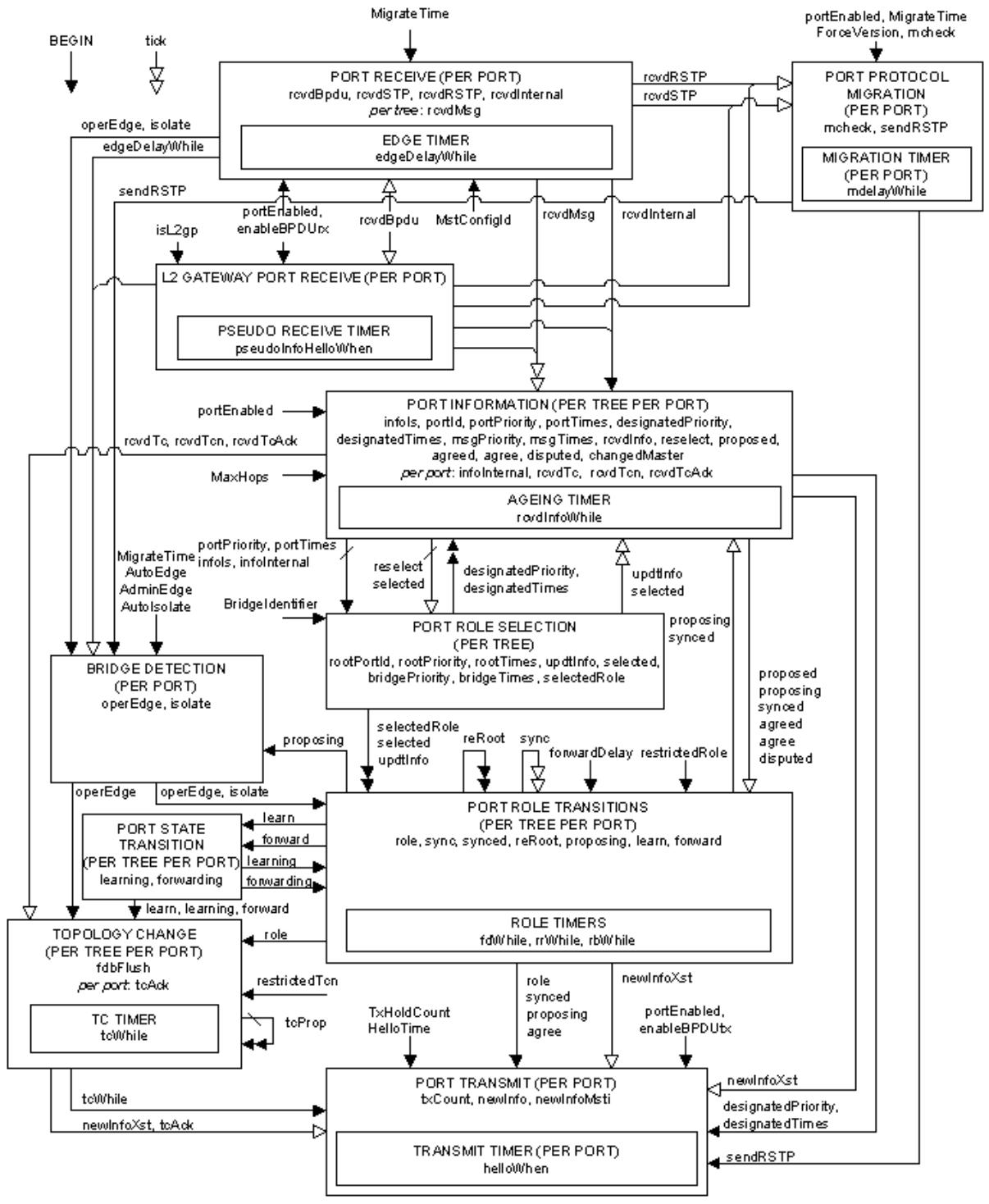
NOTE: For orvenien ce all timers are collected together into one state machine .
Figure 13-13—Spanning tree protocol state machines—overview and relationships
NOTATION:
Variables are shown both within the machine where they are principally usedand between machines where theyare used to communicate information. In the latter case they are shown with a variety of arrow styles, running from one machine to another, that provide an overview of how the variables are typically used:
Not changed by the target machine.Where the state machines are both per Port,this variable communicates between machine instances for the same port.
Set (or cleared) by the originating machine,cleared (or set) by the target machine.Where the state machinesare both per Port, this variable communicates between machine instances for the same port.
As above except that the originating per port machine instance communicates with multiple port machine instances (by setting or clearing variables owned by those Ports).
As above except that multiple per Port instances communicate with (an)other instance(s) (by seting or clearing variables owned by the originating Ports).
ABBREVIATIONS:
BDM:
PIM:
PPM:
PRS:
PRT:
PRX:
PST:
PTI:
PTX:
TCM:
Bridge Detection Machine
Port Information Machine
Port Protocol Migration Machine
Port Role Selection Machine
PortRole Transitions Machine
Port ReceiveMachine
Port State Transitions Machine
Port TImers Machine
Port Transmit Machine
Topology Change Machine
Figure 13-14—MSTP overview notation
13.25 State machine timers
The timer variables declared in this subclause are part of the specification. The accompanying descriptions are provided to aid in the comprehension of the protocol only, and are not part of the specification. Each timer variable represents an integral number of seconds before timer expiry.
One instance of the following shall be implemented per port:
a) edgeDelayWhile (13.25.1)
b) helloWhen (13.25.3)
c) mdelayWhile (13.25.4)
One instance of the following shall be implemented per port when L2GP functionality is provided:
d) pseudoInfoHelloWhen (13.25.10)
One instance per port of the following shall be implemented for the CIST and one per port for each MSTI:
e) fdWhile (13.25.2)
f) rrWhile (13.25.7)
g) rbWhile (13.25.5)
h) tcWhile (13.25.9)
i) rcvdInfoWhile (13.25.6)
j) tcDetected (13.25.8)
Table 13-5 specifies values and ranges for the initial values of timers and for transmission rate limiting performance parameters. Default values are specified to avoid the need to set values prior to operation in most cases, and are widely applicable to networks using the spanning tree protocols specified in this standard. The table recommends Bridge Hello Time, Bridge Max Age, and Bridge Forward Delay values that maximize interoperability in networks that include Bridges using STP as specified in IEEE Std 802.1D, 1998 Edition [B9]. Ranges are specified to ensure that the protocols operate correctly.
NOTE—Changes to Bridge Forward Delay do not affect reconfiguration times, unless the network includes Bridges that do not conform to this revision of this standard. Changes to Bridge Max Age can have an effect, as it is possible for old information to persist in loops in the physical topology for a number of “hops” equal to the value of Max Age in seconds, and thus exhaust the Transmit Hold Count in small loops.
Table 13-5—Timer and related parameter values
<table><tr><td>Parameter</td><td>Default</td><td>Permitted range</td><td>Interoperability recommendations</td></tr><tr><td>Migrate Time</td><td>3.0</td><td><eq>_{a}</eq></td><td><eq>_{a}</eq></td></tr><tr><td>(Bridge) Hello Time</td><td>2.0</td><td><eq>_{a}</eq></td><td><eq>_{a}</eq></td></tr><tr><td>Bridge Max Age</td><td>20.0</td><td>6.0–40.0</td><td>20.0</td></tr><tr><td>Bridge Forward Delay</td><td>15.0</td><td>4.0–30.0</td><td>15.0</td></tr><tr><td>Transmit Hold Count</td><td>6</td><td>1–10</td><td>6</td></tr><tr><td>Max Hops</td><td>20</td><td>6–40</td><td>—</td></tr></table>
All times are in seconds. —a Not applicable, value is fixed.
Bridge Max Age, Bridge Forward Delay, and Transmit Hold Count may be set by management, if this capability is provided the Bridge shall have the capability to use the full range of values in the parameter ranges specified in the “Permitted range” column of Table 13-5, with a timer resolution of r seconds, where $0 < r < = 1$ . To support interoperability with previous revisions of this standard and IEEE Std 802.1D-2004 [B10], a Bridge shall enforce the following relationships:
$$
2 \times (B r i d g e \_ F o r w a r d \_ D e l a y - 1. 0 s e c o n d s) > = B r i d g e \_ M a x \_ A g e
$$
$$
B r i d g e \_ M a x \_ A g e > = 2 \times (B r i d g e \_ H e l l o \_ T i m e + 1. 0 s e c o n d s)
$$
13.25.1 edgeDelayWhile
The Edge Delay timer. The time remaining, in the absence of a received BPDU, before this port is identified as an operEdgePort.
13.25.2 fdWhile
The Forward Delay timer. Used to delay Port State transitions until other Bridges have received spanning tree information.
13.25.3 helloWhen
The Hello timer. Used to ensure that at least one BPDU is transmitted by a Designated Port in each HelloTime period.
13.25.4 mdelayWhile
The Migration Delay timer. Used by the Port Protocol Migration state machine to allow time for another RST Bridge on the same LAN to synchronize its migration state with this port before the receipt of a BPDU can cause this port to change the BPDU types it transmits. Initialized to MigrateTime (13.26.6).
13.25.5 rbWhile
The Recent Backup timer. Maintained at its initial value, twice HelloTime, while the port is a Backup Port.
13.25.6 rcvdInfoWhile
The Received Info timer. The time remaining before information, i.e., portPriority (13.27.47) and portTimes (13.27.48), received in a Configuration Message is aged out if a further message is not received.
13.25.7 rrWhile
The Recent Root timer.
13.25.8 tcDetected
The Topology Change timer for MRP application usage. ‘New’ messages are sent while this timer is running (see 10.2).
13.25.9 tcWhile
The Topology Change timer. TCN Messages are sent while this timer is running.
13.25.10 pseudoInfoHelloWhen
The Pseudo Info Hello When timer. Used by the Layer 2 Gateway Port Receive (L2GPRX, 13.40) state machine to prompt the simulated reception at HelloTime intervals of a BPDU (see 13.29.11).
13.26 Per Bridge variables
The variables declared in this subclause (13.26) are part of the specification. The accompanying descriptions are provided to aid in the comprehension of the protocol only, and are not part of the specification.
There is one instance per Bridge component of the following variable(s):
a) ForceProtocolVersion (13.26.5)
b) TxHoldCount (13.26.12)
c) MigrateTime (13.26.6)
One instance of the following shall be implemented per Bridge component if MSTP or ISIS-SPB is implemented:
d) MstConfigId (13.26.7)
The above parameters ((a) through (d)) are not modified by the operation of the spanning tree protocols, but are treated as constants by the state machines. If ForceProtocolVersion or MSTConfigId are modified by management, BEGIN shall be asserted for all state machines.
There is one instance per Bridge of each of the following for the CIST and one for each MSTI.
e) BridgeIdentifier (13.26.2)
f) BridgePriority (13.26.3)
g) BridgeTimes (13.26.4)
h) rootPortId (13.26.9)
i) rootPriority (13.26.10)
j) rootTimes (13.26.11)
BridgeIdentifier, BridgePriority, and BridgeTimes are not modified by the operation of the spanning tree protocols but are treated as constants by the state machines. If they are modified by management, spanning tree priority vectors and Port Role assignments for all trees shall be recomputed, as specified by the operation of the Port Role Selection state machine (13.36) by clearing selected (13.27.67) and setting reselect (13.27.62) for all Bridge Ports for the relevant MSTI and for all trees if the CIST parameter is changed.
If the ISIS-SPB is implemented there is one instance per Bridge component, of the following variable(s), with that single instance supporting all SPTs:
k) agreementDigest (13.26.1)
l) AuxMstConfigId (13.26.8)
13.26.1 agreementDigest
The Agreement Digest calculated by ISIS-SPB (28.4), and updated with other calculated parameters (see 13.36).
13.26.2 BridgeIdentifier
The unique Bridge Identifier assigned to this Bridge for this tree (CIST or MSTI).
The 12-bit system ID extension component of a Bridge Identifier (14.2.5) shall be set to zero for the CIST and to the value of the MSTID for an MSTI, thus allocating distinct Bridge Identifiers to the CIST and each MSTI—all based on the use of a single Bridge Address component value for the MST Bridge as a whole.
NOTE—This convention is used to convey the MSTID for each MSTI Configuration Message in an MST BPDU.
The most significant 4 bits of the Bridge Identifier (the settable Priority component) for the CIST and for each MSTI can be modified independently of the setting of those bits for all other trees, as a part of allowing full and independent configuration control to be exerted over each spanning tree instance.
13.26.3 BridgePriority
For the CIST, the value of the CIST Bridge priority vector, as defined in 13.10. The CIST Root Identifier, CIST Regional Root Identifier, and Designated Bridge Identifier components are all equal to the value of the CIST Bridge Identifier. The remaining components (External Root Path Cost, Internal Root Path Cost, and Designated Port Identifier) are set to zero.
For a given MSTI, the value of the MSTI Bridge priority vector, as defined in 13.11. The MSTI Regional Root Identifier and Designated Bridge Identifier components are equal to the value of the MSTI Bridge Identifier (13.26.2). The remaining components (MSTI Internal Root Path Cost, Designated Port Identifier) are set to zero.
BridgePriority is used by updtRolesTree() in determining the value of the rootPriority variable (see 13.26.10).
13.26.4 BridgeTimes
For the CIST, BridgeTimes comprises
a) The current values of Bridge Forward Delay and Bridge Max Age (13.25, Table 13-5).
b) A Message Age value of zero.
c) The current value of Max Hops (13.25, Table 13-5). This parameter value is determined only by management.
For a given MSTI, BridgeTimes comprises
d) The current value of MaxHops (Max Hops in Table 13-5), the initial value of remainingHops for MSTI information generated at the boundary of an MSTI region (see 13.26.11).
BridgeTimes is used by updtRolesTree() in determining the value of the rootTimes variable (13.26.11).
13.26.5 ForceProtocolVersion
The Force Protocol Version parameter for the Bridge (13.7.2).
13.26.6 MigrateTime
The value of the Migrate Time parameter as specified in Table 13-5. This value shall not be changed.
13.26.7 MstConfigId
The current value of the Bridge’s MCID (13.8). Changes in this parameter cause BEGIN to be asserted for the state machines for the Bridge, for all trees, and for each port.
13.26.8 AuxMstConfigId
The previous value of the Bridge’s MCID (13.8). This value is saved in nonvolatile memory when certain non-critical configuration is made if the Bridge supports the ISIS-SPB non critical changes (27.4.1).
13.26.9 rootPortId
For the CIST, the Port Identifier of the Root Port, and a component of the CIST root priority vector (13.10).
For a given MSTI, the Port Identifier of the Root Port, and a component of the MSTI root priority vector (13.11).
13.26.10 rootPriority
For the CIST: the Root Identifier, External Root Path Cost, Regional Root Identifier, Internal Root Path Cost, Designated Bridge Identifier, and Designated Port Identifier components of the Bridge’s CIST root priority vector (13.10).
For a given MSTI: the MSTI Regional Root Identifier, Internal Root Path Cost, Designated Bridge Identifier, and Designated Port Identifier components of the Bridge’s MSTI root priority vector (13.11).
13.26.11 rootTimes
For the CIST, the Bridge’s timer parameter values (Message Age, Max Age, Forward Delay, and remainingHops). The values of these timers are derived (see 13.29.34) from the values stored in the CIST’s portTimes parameter (13.27.48) for the Root Port or from BridgeTimes (13.26.4).
For a given MSTI, the value of remainingHops derived (13.29.34) from the value stored in the MSTI’s portTimes parameter (13.27.48) for the Root Port or from BridgeTimes (13.26.4).
13.26.12 TxHoldCount
The value of Transmit Hold Count (Table 13-5) for the Bridge. If this is modified, the value of txCount (13.27) for all ports shall be set to zero.
13.27 Per port variables
The variables declared in this subclause (13.27) are part of the specification. The accompanying descriptions are provided to aid in the comprehension of the protocol only, and are not part of the specification.
There is one instance per port of each of the following variables:
a) AdminEdge (13.27.1)
b) ageingTime (13.27.2)
c) AutoEdge (13.27.18)
d) AutoIsolate (13.27.19)
e) enableBPDUrx (13.27.23)
f) enableBPDUtx (13.27.24)
g) ExternalPortPathCost (13.27.25)
h) isL2gp (13.27.26)
i) isolate (13.27.27)
j) mcheck (13.27.38)
k) newInfo (13.27.42)
l) operEdge (13.27.44)
m) portEnabled (13.27.45)
n) rcvdBpdu (13.27.52)
o) rcvdRSTP (13.27.56)
p) rcvdSTP (13.27.57)
q) rcvdTcAck (13.27.59)
r) rcvdTcn (13.27.60)
s) restrictedRole (13.27.64)
t) restrictedTcn (13.27.65)
u) sendRSTP (13.27.69)
v) tcAck (13.27.72)
w) tick (13.27.74)
x) txCount (13.27.75)
If MSTP or the ISIS-SPB is implemented, there is one instance per port, applicable to the CIST and to all MSTIs and SPTs, of the following variable(s):
y) rcvdInternal (13.27.54)
z) restrictedDomainRole (13.27.63)
If MSTP or the ISIS-SPB is implemented, there is one instance per port of each of the following variables for the CIST:
aa) infoInternal (13.27.31)
ab) master (13.27.36)
ac) mastered (13.27.37)
A single per port instance of the following variable(s) applies to all MSTIs:
ad) newInfoMsti (13.27.43)
If the Layer 2 Gateway Port Receive state machine (13.20, 13.40) is implemented for a port, there is one instance for the CIST, and one instance for each MSTI, for that port of the following variable:
ae) pseudoRootId (13.27.51)
If the ISIS-SPB is implemented, there is one instance per port of the following variable(s):
af) agreedMisorder (13.27.10)
ag) agreedN (13.27.11)
ah) agreedND (13.27.12)
ai) agreeN (13.27.16)
aj) agreeND (13.27.17)
If the ISIS-SPB is implemented, there is one instance per port of the following variable(s), with that single instance supporting all SPTs:
ak) agreedDigest (13.27.6)
al) agreedDigestValid (13.27.7)
am) agreeDigest (13.27.8)
an) agreeDigestValid (13.27.9)
ao) agreedTopology (13.27.14)
There is one instance per port of each of the following variables for the CIST, one per port for each MSTI and one per port for each SPT:
ap) agree (13.27.3)
aq) agreed (13.27.4)
ar) designatedPriority (13.27.20)
as) designatedTimes (13.27.21)
at) disputed (13.27.22)
au) fdbFlush (13.27.28)
av) forward (13.27.29)
aw) forwarding (13.27.30)
ax) infoIs (13.27.32)
ay) InternalPortPathCost (13.27.33)
az) learn (13.27.34)
ba) learning (13.27.35)
bb) msgPriority (13.27.39)
bc) msgTimes (13.27.40)
bd) portId (13.27.46)
be) portPriority (13.27.47)
bf) portTimes (13.27.48)
bg) proposed (13.27.49)
bh) proposing (13.27.50)
bi) rcvdInfo (13.27.53)
bj) rcvdMsg (13.27.55)
bk) rcvdTc (13.27.58)
bl) reRoot (13.27.61)
bm) reselect (13.27.62)
bn) role (13.27.66)
bo) selected (13.27.67)
bp) selectedRole (13.27.68)
bq) sync (13.27.70)
br) synced (13.27.71)
bs) tcProp (13.27.73)
bt) updtInfo (13.27.76)
If the ISIS-SPB is implemented, there is one instance per port of the following variable(s) for the CIST and one per port for each SPT:
bu) agreedPriority (13.27.13)
bv) agreementOutstanding (13.27.15)
If the ISIS-SPB is implemented, there is one instance per port of the following variables for each SPT:
bw) agreedAbove (13.27.5)
bx) neighbourPriority (13.27.41)
13.27.1 AdminEdge
A Boolean. Set by management if the port is to be identified as operEdge immediately on initialization, without a delay to detect other Bridges attached to the LAN. The recommended default value is FALSE.
13.27.2 ageingTime
FDB entries for this port are aged out after ageingTime has elapsed since they were first created or refreshed by the Learning Process. The value of this parameter is normally Ageing Time (8.8.3, Table 8-6), and is changed to FwdDelay (13.28.10) for a period of FwdDelay after fdbFlush (13.27.28) is set by the topology change state machine if stpVersion (13.28.23) is TRUE.
13.27.3 agree
A Boolean. See 13.16 and Figure 13-12.
13.27.4 agreed
A Boolean. Set, for the CIST or an MSTI, if an Agreement has been received indicating that the Port States and transmitted priority vectors for the other Bridge attached to this LAN are (and, in the absence of further communication with this Bridge and within the design probabilities of protocol failure due to repeated BPDU loss, will remain) compatible with a loop-free active topology determined by this port’s priority vectors (13.16, 13.24).
13.27.5 agreedAbove
A Boolean controlled by the updtAgreement() procedure to indicate agreement on the neighbor(s) superior priority vector.
13.27.6 agreedDigest
The Agreement Digest conveyed in the last BPDU received, if the port is internal to an SPT Region.
13.27.7 agreedDigestValid
A Boolean. TRUE if the Agreement Valid flag was set in the last BPDU or SPB Hello PDU that conveyed an Agreement Digest.
13.27.8 agreeDigest
The Agreement Digest currently encoded in SPT BPDUs transmitted from the port.
13.27.9 agreeDigestValid
A Boolean. TRUE if the Agreement Valid flag is to be set in transmitted SPT BPDUs and SPB Hello PDUs.
13.27.10 agreedMisorder
A Boolean. TRUE if the Agreement Protocol (13.16, 13.17) has received an out of order message as indicated by the received Agreement Number (13.27.16), reset when an in order message is received.
13.27.11 agreedN
The Agreement Number associated with the last BPDU received, if the port is within an SPT Region. It takes values 0, 1, 2, or 3, and all arithmetic using this variable is modulo 4, e.g., 1 + 1 = 2, 3 + 1 = 0, 0 – 1 = 3.
13.27.12 agreedND
The Discarded Agreement Number (see 13.17) to be included in SPT BPDUs transmitted from the port. The variable values 0, 1, 2, or 3, are encoded in a two-bit field and all arithmetic using this variable is modulo 4.
13.27.13 agreedPriority
The priority vector associated with the worst priority received by a CIST or SPT Designated Port from an SPT Region in SPT BPDUs that are sent by Root Ports, zero if there is no such agreement.
13.27.14 agreedTopology
A Boolean. TRUE if the Agreement Protocol has declared a topology match for agreeDigest (13.27.8), and agreeDigest has the same value as the last calculated agreementDigest (13.26.1). Reset to FALSE whenever agreementDigest is recalculated by ISIS-SPB, and set TRUE by updtDigest().
13.27.15 agreementOutstanding
The priority vector for the worst priority associated with outstanding Agreements made by a CIST or SPT Root Port, Alternate Port, or Backup Port within an SPT Region. in SPT BPDUs. When an SPT BPDU, from the same SPT Region, is received with a Discarded Agreement Number that is the immediate precursor of the current agreeN (13.27.16), the CIST’s agreementOutstanding is set to the port’s designatedPriority. On reception of a BPDU that is either not an SPT BPDU or is from a different SPT Region, the agreeND (13.27.17) is set to the value of the agreeN (13.27.16), so there is no outstanding Agreement.
13.27.16 agreeN
The Agreement Number (see 13.17) transmitted in SPT BPDUs. The variable values 0, 1, 2, or 3, are encoded in a two-bit field and arithmetic using this variable is modulo 4.
13.27.17 agreeND
The last Discarded Agreement Number (see 13.17) received in an SPT BPDU. It takes values 0, 1, 2, or 3, and arithmetic using this variable is modulo 4. If agreeND matches agreeN, there is no outstanding agreement.
13.27.18 AutoEdge
A Boolean. Set by management if the Bridge detection state machine (BDM, 13.33) is to detect other Bridges attached to the LAN, and set operEdge automatically. The recommended default is TRUE.
13.27.19 AutoIsolate
A Boolean. Set by management if isolate (13.27.27) is to be set, causing a Designated Port to transition to Discarding if both AdminEdge (13.27.1) and AutoEdge (13.27.18) are FALSE and the other Bridge presumed to be attached to the same point-to-point LAN does not transmit periodic BPDUs—either as a Designated Port or in response to BPDUs with the Proposal flag set (see 13.23). The recommended default of this parameter is FALSE. AdminEdge and AutoEdge are both reset only on ports that are known to connect to other Bridges.
13.27.20 designatedPriority
For the CIST and a given port, the CIST Root Identifier, External Root Path Cost, Regional Root Identifier, Internal Root Path Cost, Designated Bridge Identifier, and Designated Port Identifier components of the port’s CIST designated priority vector, as defined in 13.10.
For a given MSTI and port, the Regional Root Identifier, Internal Root Path Cost, Designated Bridge Identifier, and Designated Port Identifier components of the designated priority vector, as defined in 13.11.
13.27.21 designatedTimes
For the CIST and a given port, the set of timer parameter values (Message Age, Max Age, Forward Delay, and remainingHops) that are used to update Port Times when updtInfo is set. These timer parameter values are used in BPDUs transmitted from the port. The value of designatedTimes is copied from the CIST rootTimes Parameter (13.26.11) by the operation of the updtRolesTree() procedure.
For a given MSTI and port, the value of remainingHops used to update this MSTI’s portTimes parameter when updtInfo is set. This timer parameter value is used in BPDUs transmitted from the port. The updtRolesTree() procedure (13.29.34) copies designatedTimes from the MSTI’s rootTimes (13.26.11).
13.27.22 disputed
A Boolean. See 13.21, 13.20, Figure 13-20, 13.29.16, Figure 13-24, and Figure 13-25.
13.27.23 enableBPDUrx
A Boolean. This per port management parameter is set by default, and should not be clear unless the port is configured as a Layer Two Gateway Port (i.e., isL2gp is set). When clear it can allow loops to be created, or can result in no connectivity. When cleared, BPDUs received on the port are discarded and not processed.
13.27.24 enableBPDUtx
A Boolean. This per port management parameter is set by default, and should not be clear unless the port is configured as a Layer Two Gateway Port (i.e., isL2gp is set). When clear it can allow loops to be created, or can result in no connectivity. When cleared, no BPDUs are transmitted by this port.
13.27.25 ExternalPortPathCost
The port’s contribution, when it is the CIST Master Port (for MSTP and ISIS-SPB) or the CST Root Port (for RSTP and MSTP), to the External Root Path Cost (13.9) for the Bridge.
13.27.26 isL2gp
A Boolean. Set by management to identify a port configured to be a Layer Two Gateway Port. This parameter is set to FALSE by default. When set, enableBPDUtx should be cleared.
13.27.27 isolate
A Boolean. Set by the Bridge detection state machine (BDM, 13.33) when the Spanning Tree Protocol Entity of a neighboring Bridge has apparently failed (see 13.23, 13.27.19).
13.27.28 fdbFlush
A Boolean. Set by the topology change state machine to instruct the FDB to remove entries for this port, immediately if rstpVersion (13.28.21) is TRUE, or by rapid ageing (13.27.2) if stpVersion (13.28.23) is TRUE. Reset by the FDB once the entries are removed if rstpVersion is TRUE, and immediately if stpVersion is TRUE. Setting the fdbFlush variable does not result in removal of FDB entries in the case that the port is an Edge Port (i.e., operEdge is TRUE). The FDB removes entries only for those VIDs that have a fixed registration (see 10.7.2) on any port of the Bridge that is not an Edge Port.
NOTE—If MVRP or MIRP is in use, the topology change notification and flushing mechanisms defined in MRP (Clause 10) and MVRP (11.2.5) are responsible for filtering entries in the FDB for VIDs that are dynamically registered using MVRP or MIRP (i.e., for which there is no fixed registration in the Bridge on non-Edge Ports).
13.27.29 forward
A Boolean. Set or cleared by the Port Role Transitions state machine (13.37) to instruct the Port State Transitions state machine (13.38) to enable or disable forwarding.
13.27.30 forwarding
A Boolean. Set or cleared by the Port State Transitions state machine (13.38) to indicate that forwarding has been enabled or disabled.
13.27.31 infoInternal
If infoIs is Received, indicating that the port has received current information from the Designated Bridge for the attached LAN, infoInternal is set if that Designated Bridge is in the same MST Region as the receiving Bridge and reset otherwise.
13.27.32 infoIs
A variable that takes the values Mine, Aged, Received, or Disabled, to indicate the origin/state of the port’s Spanning Tree information (portInfo) held for the port, as follows:
a) If infoIs is Received, the port has received current (not aged out) information from the Designated Bridge for the attached LAN (a point-to-point Bridge link being a special case of a LAN).
b) If infoIs is Mine, information for the port has been derived from the Root Port for the Bridge (with the addition of root port cost information). This includes the possibility that the Root Port is “Port 0,” i.e., the Bridge is the Root Bridge for the Bridged Network.
c) If infoIs is Aged, information from the Root Bridge has been aged out. Just as for reselect (13.27.62), the state machine does not formally allow the Aged state to persist. However, if there is a delay in recomputing the new root port, correct processing of a received BPDU is specified.
d) Finally if the port is disabled, infoIs is Disabled.
13.27.33 InternalPortPathCost
The port’s contribution, when it is an IST or SPT Root Port (for MSTP and ISIS-SPB) to the Internal Root Path Cost (13.9) for the Bridge.
13.27.34 learn
A Boolean. Set or cleared by the Port Role Transitions state machine (13.37) to instruct the Port State Transitions state machine (13.38) to enable or disable learning.
13.27.35 learning
A Boolean. Set or cleared by the Port State Transitions state machine (13.38) to indicate that learning has been enabled or disabled.
13.27.36 master
A Boolean. Used to determine the value of the Master flag for a given MSTI and port in transmitted MST BPDUs.
Set TRUE if the Port Role for the MSTI and Port is Root Port or Designated Port, and the Bridge has selected one of its ports as the Master Port for this MSTI or the mastered flag is set for this MSTI for any other Bridge Port with a Root Port or Designated Port Role. Set FALSE otherwise.
13.27.37 mastered
A Boolean. Used to record the value of the Master flag for a given MSTI and port in MST BPDUs received from the attached LAN.
NOTE—master and mastered signal the connection of the MSTI to the CST via the Master Port throughout the MSTI. These variables and their supporting procedures do not affect the connectivity provided by this standard but permit future enhancements to MSTP providing increased flexibility in the choice of Master Port without abandoning plug-andplay network migration. They are therefore omitted from the overviews of protocol operation, including Figure 13-13.
13.27.38 mcheck
A Boolean. May be set by management to force the Port Protocol Migration state machine to transmit RST (or MST or SPT) BPDUs for a MigrateTime (13.26.6, Table 13-5) period, to test whether all STP Bridges on the attached LAN have been removed and the port can continue to transmit RST BPDUs. Setting mcheck has no effect if stpVersion (13.28.23) is TRUE.
13.27.39 msgPriority
For the CIST and a given port, the CIST Root Identifier, External Root Path Cost, Regional Root Identifier, Internal Root Path Cost, Designated Bridge Identifier, and Designated Port Identifier components of the CIST message priority vector conveyed in a received BPDU, as defined in 13.10.
For a given MSTI and port, the Regional Root Identifier, Internal Root Path Cost, Designated Bridge Identifier, and Designated Port Identifier components of the MSTI message priority vector, as defined in 13.11 and conveyed in a received BPDU for this MSTI.
13.27.40 msgTimes
For the CIST and a given port, the timer parameter values (Message Age, Max Age, Forward Delay, Hello Time, and remainingHops) conveyed in a received BPDU. If the BPDU is an STP or RST BPDU without MSTP parameters, remainingHops is set to the value of the MaxHops component of BridgeTimes (13.26.4).
For a given MSTI and port, the value of remainingHops received in the same BPDU as the message priority components of this MSTI’s msgPriority parameter.
13.27.41 neighbourPriority
For a port attached to a point-to-point LAN within the same SPT Region, the designated priority of the other Bridge attached to that LAN as calculated by ISIS-SPB for a given SPT. Receipt of an Agreement Digest matching the Bridge component’s agreementDigest implies receipt of an Agreement, with agreedPriority == neighbourPriority, for each SPT for which the port’s selectedRole is DesignatedPort.
If the port is attached to a shared media LAN that is within the same SPT Region, i.e., all Bridges attached to that LAN are within the Region, then neighbourPriority is the best (13.9) of all the neighbor’s calculated designated priority vectors, and an SPT BPDU with a matching digest has to be received from all the neighbors before agreedPriority is updated.
13.27.42 newInfo
A Boolean. Set TRUE if a BPDU conveying changed CIST information is to be transmitted. It is set FALSE by the Port Transmit state machine.
13.27.43 newInfoMsti
A Boolean. Set TRUE if a BPDU conveying changed MSTI information is to be transmitted. It is set FALSE by the Port Transmit state machine.
13.27.44 operEdge
A Boolean. The value of the operEdgePort parameter [item l) in 12.18.2.1.3], as determined by the operation of the Bridge Detection state machine (13.33).
13.27.45 portEnabled
A Boolean. Set if the Bridge’s MAC Relay Entity and Spanning Tree Protocol Entity can use the MAC Service provided by the Bridge Port’s MAC entity to transmit and receive frames to and from the attached LAN, i.e., portEnabled is TRUE if and only if
a) MAC_Operational (IEEE Std 802.1AC) is TRUE; and
b) Administrative Bridge Port State (8.4, 13.12) for the port is Enabled.
13.27.46 portId
The Port Identifier for this port. This variable forms a component of the port priority and designated priority vectors (13.10, 13.11).
The most significant 4 bits of the Port Identifier (the settable Priority component) for the CIST and for each MSTI can be modified independently of the setting of those bits for all other trees, as a part of allowing full and independent configuration control to be exerted over each spanning tree instance.
13.27.47 portPriority
For the CIST and a given port, the CIST Root Identifier, External Root Path Cost, Regional Root Identifier, Internal Root Path Cost, Designated Bridge Identifier, and Designated Port Identifier components of the port’s port priority vector (13.10).
For a given MSTI and port, the Regional Root Identifier, Internal Root Path Cost, Designated Bridge Identifier, and Designated Port Identifier components of the port’s MSTI port priority vector (13.11).
13.27.48 portTimes
For the CIST and a given port, the port’s timer parameter values (Message Age, Max Age, Forward Delay, Hello Time, and remainingHops). The Hello Time timer parameter value is used in transmitted BPDUs.
For a given MSTI and port, the value of remainingHops for this MSTI in transmitted BPDUs.
13.27.49 proposed
A Boolean. See 13.16, Figure 13-10, Figure 13-12, 13.29.14, 13.29.19, 13.37, and Figure 13-24.
13.27.50 proposing
A Boolean. See 13.16, Figure 13-10, Figure 13-12, 13.29.14, 13.29.15, 13.33, and Figure 13-25.
13.27.51 pseudoRootId
A Bridge Identifier configured by management for L2GP operation. By default, it is set to the BridgeIdentifier (13.26.2).
13.27.52 rcvdBPDU
A Boolean. Set by system-dependent processes, this variable notifies the Port Receive state machine (13.31) when a valid (Clause 14) Configuration, TCN, RST, MST, or SPT BPDU (14.3) is received on the port. Reset by the Port Receive state machine.
13.27.53 rcvdInfo
Set to the result of the rcvInfo() procedure (13.29.12).
13.27.54 rcvdInternal
A Boolean. Set TRUE by the Receive Machine if the BPDU received was transmitted by a Bridge in the same MST Region as the receiving Bridge.
13.27.55 rcvdMsg
A Boolean. See 13.29.13 and 13.31.
13.27.56 rcvdRSTP
A Boolean. See 13.31, 13.29.31, and 13.32.
13.27.57 rcvdSTP
A Boolean. See 13.31, 13.29.31, and 13.32.
13.27.58 rcvdTc
A Boolean. See 13.29.13, 13.29.24, and 13.39.
13.27.59 rcvdTcAck
A Boolean. See 13.29.24 and 13.39.
13.27.60 rcvdTcn
A Boolean. See 13.29.13, 13.29.24, and 13.39.
13.27.61 reRoot
A Boolean. Set by a newly selected Root Port to force prior Root Ports to Discarding, before it becomes forwarding. See Figure 13-24, 13.29.21, Figure 13-23, Figure 13-25, and Figure 13-26.
13.27.62 reselect
A Boolean. Set to prompt recomputation of the CIST or an MSTI. See 13.35 and 13.36.
13.27.63 restrictedDomainRole
A Boolean. Set by management. If TRUE, causes a port that is a Boundary Port of an SPT Region not to be selected as Root Port for the CIST, any MSTI, or any SPT, even it has the best spanning tree priority vector. See 13.20, 27.7, and restrictedRole (13.27.64).
13.27.64 restrictedRole
A Boolean. Set by management. If TRUE causes the port not to be selected as Root Port for the CIST or any MSTI, even it has the best spanning tree priority vector. Such a port will be selected as an Alternate Port after the Root Port has been selected. This parameter should be FALSE by default. If set, it can cause lack of spanning tree connectivity. It is set by a network administrator to prevent Bridges external to a core region of the network influencing the spanning tree active topology, possibly because those Bridges are not under the full control of the administrator.
13.27.65 restrictedTcn
A Boolean. Set by management. If TRUE causes the port not to propagate received topology change notifications and topology changes to other ports. This parameter should be FALSE by default. If set it can cause temporary loss of connectivity after changes in a spanning trees active topology as a result of persistent incorrectly learned station location information. It is set by a network administrator to prevent Bridges external to a core region of the network, causing address flushing in that region, possibly because those Bridges are not under the full control of the administrator or MAC_Operational for the attached LANs transitions frequently.
13.27.66 role
The current Port Role. DisabledPort, RootPort, DesignatedPort, AlternatePort, BackupPort, or MasterPort.
NOTE—The MasterPort role applies to each MSTI when the CIST Port Role is RootPort and connects to another MST Region. An MSTI Master Port is part of the stable active topology for frames assigned to that MSTI, just as the CIST Root Port forwards frames for the IST. The Port State for each MSTI may differ as required to suppress temporary loops.
13.27.67 selected
A Boolean. See 13.36 and 13.29.22.
13.27.68 selectedRole
A newly computed role for the port.
13.27.69 sendRSTP
A Boolean. See 13.32 and 13.34.
13.27.70 sync
A Boolean. Set to force the Port State to be compatible with the loop-free active topology determined by the priority vectors held by this Bridge (13.16, 13.24) for this tree (CIST or MSTI), transitioning the Port State to Discarding, and soliciting an Agreement if possible, if the port is not already synchronized (13.27.71).
13.27.71 synced
A Boolean. TRUE only if the Port State is compatible with the loop-free active topology determined by the priority vectors held by this Bridge for this tree (13.16, 13.24).
13.27.72 tcAck
A Boolean. Set to transmit a Configuration Message with a topology change acknowledge flag set.
13.27.73 tcProp
A Boolean. Set by the Topology Change state machine of any other port, to indicate that a topology change should be propagated through this port.
13.27.74 tick
A Boolean. See the Port Timers state machine (13.30).
13.27.75 txCount
A counter. Incremented by the Port Transmission (13.34) state machine on every BPDU transmission, and decremented used by the Port Timers state machine (13.30) once a second. Transmissions are delayed if txCount reaches TxHoldCount (13.26.12).
13.27.76 updtInfo
A Boolean. Set by the Port Role Selection state machine (13.36, 13.29.34) to tell the Port Information state machine that it should copy designatedPriority to portPriority and designatedTimes to portTimes.
13.28 State machine conditions and parameters
The following variable evaluations are defined for notational convenience in the state machines:
a) allSptAgree (13.28.1)
b) allSynced (13.28.2)
c) allTransmitReady (13.28.3)
d) BestAgreementPriority (13.28.4)
e) cist (13.28.5)
f) cistRootPort (13.28.6)
g) cistDesignatedPort (13.28.7)
h) EdgeDelay (13.28.8)
i) forwardDelay (13.28.9)
j) FwdDelay (13.28.10)
k) HelloTime (13.28.11)
l) MaxAge (13.28.12)
m) msti (13.28.13)
n) mstiDesignatedOrTCpropagatingRootPort (13.28.14)
o) mstiMasterPort (13.28.15)
p) operPointToPointMAC (13.28.16)
q) rcvdAnyMsg (13.28.17)
r) rcvdCistMsg (13.28.18)
s) rcvdMstiMsg (13.28.19)
t) reRooted (13.28.20)
u) rstpVersion (13.28.21)
v) spt (13.28.22)
w) stpVersion (13.28.23)
x) updtCistInfo (13.28.24)
y) updtMstiInfo (13.28.25)
13.28.1 allSptAgree
TRUE, if and only if, agree is TRUE for the given port for all SPTs.
13.28.2 allSynced
The condition allSynced is TRUE for a given port, for a given tree, if and only if
a) For all ports for the given tree, selected is TRUE, the port’s role is the same as its selectedRole, and updtInfo is FALSE; and
b) The role of the given port is
1) Root Port or Alternate Port and synced is TRUE for all ports for the given tree other than the Root Port; or
2) Designated Port and synced is TRUE for all ports for the given tree other than the given port; or
3) Designated Port, and the tree is an SPT or the IST, and the Root Port of the tree and the given port are both within the Bridge’s SPT Region, and both learning and forwarding are FALSE for the given port; or
4) Master Port and synced is TRUE for all ports for the given tree other than the given port.
13.28.3 allTransmitReady
TRUE, if and only if, for the given port for all trees
a) selected is TRUE; and
b) updtInfo is FALSE.
13.28.4 BestAgreementPriority
The best of all possible priority vectors, i.e., numerically the lowest.
13.28.5 cist
TRUE only for CIST state machines; i.e., FALSE for MSTI or SPT state machine instances.
13.28.6 cistRootPort
TRUE if the CIST role for the given port is RootPort.
13.28.7 cistDesignatedPort
TRUE if the CIST role for the given port is DesignatedPort.
13.28.8 EdgeDelay
Returns the value of MigrateTime if operPointToPointMAC is TRUE, and the value of MaxAge otherwise.
13.28.9 forwardDelay
Returns the value of HelloTime if sendRSTP is TRUE, and the value of FwdDelay otherwise.
13.28.10 FwdDelay
The Forward Delay component of the CIST’s designatedTimes parameter (13.27.21).
13.28.11 HelloTime
The Hello Time component of the CIST’s portTimes parameter (13.27.48) with the recommended default value given in Table 13-5.
13.28.12 MaxAge
The Max Age component of the CIST’s designatedTimes parameter (13.27.21).
13.28.13 msti
TRUE only for MSTI state machines; i.e., FALSE for CIST or SPT state machine instances.
13.28.14 mstiDesignatedOrTCpropagatingRootPort
TRUE if the role for any MSTI for the given port is either
a) DesignatedPort; or
b) RootPort, and the instance for the given MSTI and port of the tcWhile timer is not zero.
13.28.15 mstiMasterPort
TRUE if the role for any MSTI for the given port is MasterPort.
13.28.16 operPointToPoint
TRUE if operPointToPointMAC (IEEE Std 802.1AC) is TRUE for the Bridge Port.
13.28.17 rcvdAnyMsg
TRUE for a given port if rcvdMsg is TRUE for the CIST or any MSTI for that port.
13.28.18 rcvdCistMsg
TRUE for a given port if and only if rcvdMsg is TRUE for the CIST for that port.
13.28.19 rcvdMstiMsg
TRUE for a given port and MSTI if and only if rcvdMsg is FALSE for the CIST for that port and rcvdMsg is TRUE for the MSTI for that port.
13.28.20 reRooted
TRUE if the rrWhile timer is clear (zero) for all Ports for the given tree other than the given Port.
13.28.21 rstpVersion
TRUE if ForceProtocolVersion (13.7.2) is greater than or equal to 2.
13.28.22 spt
TRUE only for SPT state machines, in an SPT Bridge; i.e., FALSE for CIST and MSTI state machine instances.
13.28.23 stpVersion
TRUE if Force Protocol Version (13.7.2) is less than 2.
13.28.24 updtCistInfo
TRUE for a given port if and only if updtInfo is TRUE for the CIST for that port.
13.28.25 updtMstiInfo
TRUE for a given port and MSTI if and only if updtInfo is TRUE for the MSTI for that port or updtInfo is TRUE for the CIST for that port.
NOTE—The dependency of rcvdMstiMsg and updtMstiInfo on CIST variables for the port reflects the fact that MSTIs exist in a context of CST parameters. The state machines ensure that the CIST parameters from received BPDUs are processed and updated prior to processing MSTI information.
13.29 State machine procedures
The following procedures perform the functions specified for both the state machines for all trees, or specifically for the CIST, a given MSTI, or a given SPT:
a) betterorsameInfo(newInfoIs) (13.29.1)
b) clearAllRcvdMsgs() (13.29.2)
c) clearReselectTree() (13.29.3)
d) disableForwarding() (13.29.4)
e) disableLearning() (13.29.5)
f) enableForwarding() (13.29.6)
g) enableLearning() (13.29.7)
h) fromSameRegion() (13.29.8)
i) newTcDetected() (13.29.9)
j) newTcWhile() (13.29.10)
k) pseudoRcvMsgs() (13.29.11)
l) rcvInfo() (13.29.12)
m) rcvMsgs() (13.29.13)
n) recordAgreement() (13.29.15)
o) recordDispute() (13.29.16)
p) recordMastered() (13.29.17)
q) recordPriority() (13.29.18)
r) recordProposal() (13.29.19)
s) recordTimes() (13.29.20)
t) setReRootTree() (13.29.21)
u) setSelectedTree() (13.29.22)
v) setSyncTree() (13.29.23)
w) setTcFlags() (13.29.24)
x) setTcPropTree() (13.29.25)
y) syncMaster() (13.29.26)
z) txConfig() (13.29.27)
aa) txRstp() (13.29.28)
ab) txTcn() (13.29.29)
ac) updtBPDUVersion() (13.29.31)
ad) updtRcvdInfoWhile() (13.29.33)
ae) updtRolesTree() (13.29.34)
af) updtRolesDisabledTree() (13.29.35)
The following procedures perform the functions specified for all SPTs, or for a given SPT or the CIST when ISIS-SPB is implemented:
ag) rcvAgreements() (13.29.14)
ah) updtAgreement() (13.29.30)
ai) updtDigest() (13.29.32)
All references to named variables in the specification of procedures are to instances of the variables corresponding to the instance of the state machine using the function, i.e., to the CIST or the given MSTI or the given SPT as appropriate. References to forwarding and learning apply to frames assigned to the specified tree.
13.29.1 betterorsameInfo(newInfoIs)
Returns TRUE if, for a given port and tree (CIST or MSTI), either
a) The procedure’s parameter newInfoIs is Received, and infoIs is Received and the msgPriority vector is better than or the same as (13.10) the portPriority vector; or,
b) The procedure’s parameter newInfoIs is Mine, and infoIs is Mine and the designatedPriority vector is better than or the same as (13.10) the portPriority vector.
Returns False otherwise.
NOTE—This procedure is not invoked (in the case of a MSTI) if the received BPDU carrying the MSTI information was received from another MST Region. In that event, the Port Receive Machine (using rcvMsgs()) does not set rcvdMsg for any MSTI, and the Port Information Machine’s SUPERIOR_DESIGNATED state is not entered.
13.29.2 clearAllRcvdMsgs()
Clears rcvdMsg for the CIST and all MSTIs, for this port.
13.29.3 clearReselectTree()
Clears reselect for the tree (the CIST or a given MSTI) for all ports of the Bridge.
13.29.4 disableForwarding()
An implementation-dependent procedure that causes the Forwarding Process (8.6) to stop forwarding frames through the port. The procedure does not complete until forwarding has stopped.
13.29.5 disableLearning()
An implementation-dependent procedure that causes the Learning Process (8.7) to stop learning from the source address of frames received on the port. The procedure does not complete until learning has stopped.
13.29.6 enableForwarding()
An implementation-dependent procedure that causes the Forwarding Process (8.6) to start forwarding frames through the port. The procedure does not complete until forwarding has been enabled.
13.29.7 enableLearning()
An implementation-dependent procedure that causes the Learning Process (8.7) to start learning from frames received on the port. The procedure does not complete until learning has been enabled.
13.29.8 fromSameRegion()
Returns TRUE if rcvdRSTP is TRUE, and the received BPDU conveys a MCID that matches that held for the Bridge. Returns FALSE otherwise. If SPB protocols are implemented, fromSameRegion() returns TRUE if the Bridge detects that either its MCID (13.26.7) or its Auxiliary MCID (13.26.8) match either the MCID or Auxiliary MCID carried by the received SPT BPDU.
13.29.9 newTcDetected()
If the value of tcDetected is zero and sendRSTP is TRUE, this procedure sets the value of tcDetected to HelloTime plus one second. The value of HelloTime is taken from the CIST’s portTimes parameter (13.27.48) for this port.
If the value of tcDetected is zero and sendRSTP is FALSE, this procedure sets the value of tcDetected to the sum of the Max Age and Forward Delay components of rootTimes.
Otherwise, the procedure takes no action.
13.29.10 newTcWhile()
If the value of tcWhile is zero and sendRSTP is TRUE, this procedure sets the value of tcWhile to HelloTime plus one second and sets either newInfo TRUE for the CIST or newInfoMsti TRUE for a given MSTI. The value of HelloTime is taken from the CIST’s portTimes parameter (13.27.48) for this port.
If the value of tcWhile is zero and sendRSTP is FALSE, this procedure sets the value of tcWhile to the sum of the Max Age and Forward Delay components of rootTimes and does not change the value of either newInfo or newInfoMsti.
Otherwise, the procedure takes no action.
13.29.11 pseudoRcvMsgs()
Using local parameters, this procedure simulates the processing that would be applied by rcvInfo() and rcvMsgs() to a BPDU received on the port, from the same region and with the following parameters:
a) Message Age, Max Age, Hello Time and Forward Delay are derived from BridgeTimes (13.26.4);
b) The CIST information carries the message priority vector (13.10) with a value of {pseudoRootId, 0, pseudoRootId, 0, 0, 0};
c) A CIST Port Role of Designated Port, with the Learning and Forwarding flags set;
d) The Version 1 Length is 0 and Version 3 Length calculated appropriately;
e) For each MSTI configured on the Bridge, the corresponding MSTI Configuration Message carries:
1) A message priority vector with a value of {pseudoRootId, 0, 0, 0};
2) A Port Role of Designated Port, with the Learning and Forwarding flags set;
3) MSTI Remaining Hops set to the value of the MaxHops component of BridgeTimes (13.26.4).
NOTE—If two L2GP ports are configured with the same CIST pseudoRootId then the IST may partition within the MST Region, but either of the L2GP ports can be selected to provide connectivity from the Region/customer network to a provider’s network on an MSTI by MSTI basis.
13.29.12 rcvInfo()
Returns SuperiorDesignatedInfo if, for a given port and tree (CIST or MSTI):
a) The received CIST or MSTI message conveys a Designated Port Role, and
1) The message priority (msgPriority—13.27.39) is superior (13.10 or 13.11) to the port’s port priority vector, or
2) The message priority is the same as the port’s port priority vector, and any of the received timer parameter values (msgTimes—13.27.40) differ from those already held for the port (portTimes—13.27.48).
Otherwise, returns RepeatedDesignatedInfo if, for a given port and tree (CIST or MSTI):
b) The received CIST or MSTI message conveys a Designated Port Role, and
1) A message priority vector and timer parameters that are the same as the port’s port priority vector and timer values; and
2) infoIs is Received.
Otherwise, returns InferiorDesignatedInfo if, for a given port and tree (CIST or MSTI):
c) The received CIST or MSTI message conveys a Designated Port Role.
Otherwise, returns InferiorRootAlternateInfo if, for a given port and tree (CIST or MSTI):
d) The received CIST or MSTI message conveys a Root Port, Alternate Port, or Backup Port Role and a CIST or MSTI message priority that is the same as or worse than the CIST or MSTI port priority vector.
Otherwise, returns OtherInfo.
NOTE—A Configuration BPDU implicitly conveys a Designated Port Role.
13.29.13 rcvMsgs()
This procedure is invoked by the Port Receive state machine (13.31) to decode a received BPDU. Sets rcvdTcn and rcvdTc for each and every MSTI if a TCN BPDU has been received, and extracts the message priority and timer values from the received BPDU storing them in the msgPriority and msgTimes variables.
If ISIS-SPB is implemented, ForceProtocolVersion is 4 (or greater), the BPDU is an SPT BPDU, and has been received on a Bridge Port that is internal to the SPT Region (i.e., is not a Boundary Port, see 13.12), then the rcvAgreements() procedure processes the CIST and SPT information conveyed by the BPDU.
Otherwise (i.e., if rcvAgreements() is not used), this procedure sets rcvdMsg for the CIST and makes the received CST or CIST message available to the CIST Port Information state machines.
If and only if rcvdInternal is set, this procedure sets rcvdMsg for each and every MSTI for which a MSTI message is conveyed in the BPDU, and makes available each MSTI message and the common parts of the CIST message priority (the CIST Root Identifier, External Root Path Cost, and Regional Root Identifier) to the Port Information state machine for that MSTI.
13.29.14 rcvAgreements()
This procedure is used to process agreements received in SPT BPDUs and in SPB Hello PDUs. The same variables are used in both cases. In the case of SPT BPDUs, this procedure is invoked by the rcvMsgs() procedure that decodes received BPDUs.
If the received Agreement Number is equal to the value of agreedN plus three, agreedMisorder is set TRUE.
The variables agreedN and agreeND are set to the values of the received Agreement Number and Discard Agreement Number, respectively. The variables agreedDigest and agreedDigestValid are updated with the values of the received Agreement Digest and Agreement Digest flag, respectively.
The CIST proposed flag is set to the value of the Proposal flag for the CIST in the received BPDU.
The updtDigest() procedure is invoked. The updtAgreement() procedure is invoked for the port, for the CIST and for each SPT.
13.29.15 recordAgreement()
For the CIST and a given port, if rstpVersion is TRUE, operPointToPointMAC (IEEE Std 802.1AC) is TRUE, and the received CIST Message has the Agreement flag set, then the CIST agreed flag is set and the CIST proposing flag is cleared. Otherwise, the CIST agreed flag is cleared. Additionally, if the CIST message was received from a Bridge in a different MST Region, i.e., the rcvdInternal flag is clear, the agreed and proposing flags for this port for all MSTIs are set or cleared to the same value as the CIST agreed and proposing flags. If the CIST message was received from a Bridge in the same MST Region, the MSTI agreed and proposing flags are not changed.
For a given MSTI and port, if operPointToPointMAC (IEEE Std 802.1AC) is TRUE, and
a) The message priority vector of the CIST Message accompanying the received MSTI Message (i.e., received in the same BPDU) has the same CIST Root Identifier, CIST External Root Path Cost, and Regional Root Identifier as the CIST port priority vector, and
b) The received MSTI Message has the Agreement flag set,
the MSTI agreed flag is set and the MSTI proposing flag is cleared. Otherwise, the MSTI agreed flag is cleared.
NOTE—MSTI Messages received from Bridges external to the MST Region are discarded and not processed by recordAgreeement() or recordProposal().
13.29.16 recordDispute()
For the CIST and a given port, if the CIST message has the learning flag set:
a) The disputed variable is set; and
b) The agreed variable is cleared.
Additionally, if the CIST message was received from a Bridge in a different MST region (i.e., if the rcvdInternal flag is clear), then for all the MSTIs:
c) The disputed variable is set; and
d) The agreed variable is cleared.
For a given MSTI and port, if the received MSTI message has the learning flag set:
e) The disputed variable is set; and
f) The agreed variable is cleared.
13.29.17 recordMastered()
For the CIST and a given port, if the CIST message was received from a Bridge in a different MST Region, i.e., the rcvdInternal flag is clear, the mastered variable for this port is cleared for all MSTIs.
For a given MSTI and port, if the MSTI message was received on a point-to-point link and the MSTI Message has the Master flag set, set the mastered variable for this MSTI. Otherwise, reset the mastered variable.
13.29.18 recordPriority()
Sets the components of the portPriority variable to the values of the corresponding msgPriority components.
13.29.19 recordProposal()
For the CIST and a given port, if the received CIST Message conveys a Designated Port Role, and has the Proposal flag set, the CIST proposed flag is set. Otherwise, the CIST proposed flag is not changed. Additionally, if the CIST Message was received from a Bridge in a different MST Region, i.e., the rcvdInternal flag is clear, the proposed flags for this port for all MSTIs are set or cleared to the same value as the CIST proposed flag. If the CIST message was received from a Bridge in the same MST Region, the MSTI proposed flags are not changed.
For a given MSTI and port, if the received MSTI Message conveys a Designated Port Role, and has the Proposal flag set, the MSTI proposed flag is set. Otherwise, the MSTI proposed flag is not changed.
13.29.20 recordTimes()
For the CIST and a given port, sets portTimes’ Message Age, Max Age, Forward Delay, and remainingHops to the received values held in msgTimes and portTimes’ Hello Time to the default specified in Table 13-5.
For a given MSTI and port, sets portTime’s remainingHops to the received value held in msgTimes.
13.29.21 setReRootTree()
Sets reRoot TRUE for this tree (the CIST or a given MSTI) for all ports of the Bridge.
13.29.22 setSelectedTree()
Sets selected TRUE for this tree (the CIST or a given MSTI) for all ports of the Bridge if reselect is FALSE for all ports in this tree. If reselect is TRUE for any port in this tree, this procedure takes no action.
13.29.23 setSyncTree()
Sets sync TRUE for this tree (the CIST or a given MSTI) for all ports of the Bridge.
13.29.24 setTcFlags()
For the CIST and a given port:
a) If the Topology Change Acknowledgment flag is set for the CIST in the received BPDU, sets rcvdTcAck TRUE.
b) If rcvdInternal is clear and the Topology Change flag is set for the CIST in the received BPDU, sets rcvdTc TRUE for the CIST and for each and every MSTI.
c) If rcvdInternal is set, sets rcvdTc for the CIST if the Topology Change flag is set for the CIST in the received BPDU.
For a given MSTI and port, sets rcvdTc for this MSTI if the Topology Change flag is set in the corresponding MSTI message.
13.29.25 setTcPropTree()
If and only if restrictedTcn is FALSE for the port that invoked the procedure, sets tcProp TRUE for the given tree (the CIST or a given MSTI) for all other ports.
13.29.26 syncMaster()
For all MSTIs, for each port that has infoInternal set:
a) Clears the agree, agreed, and synced variables; and
b) Sets the sync variable.
13.29.27 txConfig()
Transmits a Configuration BPDU. The first four components of the message priority vector (13.27.39) conveyed in the BPDU are set to the value of the CIST Root Identifier, External Root Path Cost, Bridge Identifier, and Port Identifier components of the CIST’s designatedPriority parameter (13.27.20) for this port. The topology change flag is set if (tcWhile != 0) for the port. The topology change acknowledgment flag is set to the value of tcAck for the port. The remaining flags are set to zero. The value of the Message Age, Max Age, and Fwd Delay parameters conveyed in the BPDU are set to the values held in the CIST’s designatedTimes parameter (13.27.21) for the port. The value of the Hello Time parameter conveyed in the BPDU is set to the value held in the CIST’s portTimes parameter (13.27.48) for the port.
13.29.28 txRstp()
Transmits a RST BPDU, MST BPDU, or SPT BPDU as determined by the value of ForceProtocolVersion (13.7.2), and encoded as specified by Clause 14. All per port variables referenced in this subclause (13.29.28) are those for the transmitting port.
The first six components of the CIST message priority vector (13.27.39) conveyed in the BPDU are set to the value of the CIST’s designatedPriority parameter (13.27.20). The Port Role in the BPDU (14.2.9) is set to the current value of the CIST’s role (13.27.66). The Agreement and Proposal flags in the BPDU are set to the values of agree (13.27.3) and proposing (13.27.50), respectively. The CIST topology change flag is set if (tcWhile != 0) for the port. The topology change acknowledge flag in the BPDU is never used and is set to zero. The Learning and Forwarding flags in the BPDU are set to the values of learning (13.27.35) and forwarding (13.27.30) for the CIST, respectively. The value of the Message Age, Max Age, and Fwd Delay parameters conveyed in the BPDU are set to the values held in the CIST’s designatedTimes parameter (13.27.21). The value of the Hello Time parameter conveyed in the BPDU is set to the value held in the CIST’s portTimes parameter (13.27.48).
If the value of the Force Protocol Version parameter is less than 3, no further parameters are encoded in the BPDU and the protocol version parameter is set to 2 (denoting a RST BPDU). Otherwise, MST BPDU parameters are encoded:
a) The version 3 length.
b) The MST Configuration Identifier parameter of the BPDU is the value of MstConfigId (13.26.7).
c) The CIST Internal Root Path Cost (13.27.20).
d) The CIST Bridge Identifier (CIST Designated Bridge Identifier—13.27.20).
e) The CIST Remaining Hops (13.27.21).
f) The parameters of each MSTI message, encoded in MSTID order.
NOTE—No more than 64 MSTIs may be supported. The parameter sets for all of these can be encoded in a standardsized Ethernet frame. The number of MSTIs supported can be zero: an SPT Bridge, for example, is not obliged to have MSTIs configured in order to support SPB.
If the value of the Force Protocol Version parameter is less than 3, no further parameters are encoded in the BPDU and the protocol version parameter is set to 3 (denoting a MST BPDU). Otherwise, SPT BPDU parameters are encoded, and the protocol version parameter is set to 4 (denoting an SPT BPDU):
g) agreeN (13.27.16) is encoded in the Agreement Number field.
h) agreedND (13.27.17) is encoded in the Discarded Agreement Number field.
i) agreeDigest (13.27.8) is encoded in the Agreement Digest field.
13.29.29 txTcn()
Transmits a TCN BPDU.
13.29.30 updtAgreement()
If ISIS-SPB is implemented, this procedure is invoked for a given port, for the CIST or a given SPT, by the updtRolesTree() procedure used by the Port Role Selection machine (13.36), and by the rcvAgreements() procedure. The Port Role Selection machine itself could have been invoked following receipt of a BPDU on a port that is at the boundary of the SPT Region, possibly changing the context for the link state calculation, or following a link state update computed by ISIS-SPB following receipt of an IS-IS PDU.
If the procedure has been invoked for the CIST:
a) If the port’s selectedRole is DesignatedPort, agreed is TRUE if and only if
1) agreedTopology is TRUE; and
2) designatedPriority is the same or better (13.9) than agreedPriority.
b) If the port’s selectedRole is not DesignatedPort, agreed is TRUE if and only if
1) agreementOutstanding is the same or better than designatedPriority.
If the procedure has been invoked for an SPT, and the port’s selectedRole is DesignatedPort:
c) agreedAbove is reset to FALSE;
d) if agreedTopology is TRUE:
1) agreementOutstanding (13.27.15) is set to BestAgreementPriority (13.28.4); and
2) agreedPriority (13.27.13) is set to the sum of neighbourPriority (13.27.41) and InternalPortPathCost.
e) if agreedTopology is FALSE and agreedPriority is less than the sum of neighbourPriority and InternalPortPathCost:
1) agreedPriority (13.27.13) is set to the sum of neighbourPriority (13.27.41) and InternalPortPathCost.
f) agreed (13.27.4) is TRUE if and only if
1) designatedPriority is better than agreedPriority.
If the procedure has been invoked for an SPT and the port’s selectedRole is not DesignatedPort:
g) agreedPriority is set to BestAgreementPriority;
h) if agreedTopology is TRUE:
1) agreedAbove is set TRUE, and
2) agreementOutstanding (13.27.15) is set is set to the sum of neighbourPriority (13.27.41) and InternalPortPathCost.
i) if agreedTopology is FALSE and agreementOutstanding is better than the sum of neighbourPriority and InternalPortPathCost:
1) agreementOutstanding is set to the sum of neighbourPriority (13.27.41) and InternalPortPathCost.
j) agreed is TRUE if and only if
1) agreedAbove is TRUE, and
2) agreementOutstanding is the same as or better than designatedPriority.
Independently of whether the procedure was invoked for the CIST or an SPT:
k) if agreed is FALSE, then the sync variable is set TRUE.
13.29.31 updtBPDUVersion()
Sets rcvdSTP TRUE if the BPDU received is a version 0 or version 1 TCN or a Config BPDU. Sets rcvdRSTP TRUE if the received BPDU is a RST BPDU or a MST BPDU.
13.29.32 updtDigest()
Updates agreeDigest and agreeN, following calculation of a new topology or topologies by ISIS-SPB, and checks for a topology match with the updated values of those variables, as follows.
If agreeDigest is not equal to agreementDigest and
a) agreeN is equal to agreeND, or
b) agreeN plus one is equal to agreeND:
c) agreeDigest is set equal to agreementDigest, and
d) agreeDigestValid is reset to FALSE, and
e) agreeN is set equal to agreeN plus one.
Additionally, if agreeDigest is now equal to agreementDigest and
f) agreeDigest equals agreedDigest, and
g) agreedDigestValid is TRUE:
then
h) if agreedND is not equal to agreedN plus one, then
1) agreedND is set equal to agreedN plus one, and
2) newInfoMsti is set.
and
i) if agreeND is equal to agreeN and agreedMisorder is FALSE, or
j) if agreeND is set equal to agreeN plus one, then
1) agreedTopology is set TRUE, and
2) agreedMisorder is set FALSE;
otherwise, i.e., if (f) and (g) above are not both TRUE:
k) if agreedND is not equal to agreedN, then
1) agreedND is set equal to agreedN, and
2) newInfoMsti is set.
The agreeDigest, agreeN, and agreedND variables determine the values of the Agreement Digest, Agreement Number (AN), and Discarded Agreement Number (DAN), transmitted in SPT BPDU and SPB Hello PDUs. This procedure is used by updtRolesTree() before using updtAgreement() for each SPT, and also by rcvAgreements(), since the latter can rotate the AN sequence window number and thus allow agreeDigest to be updated with agreementDigest.
Wherever newInfoMsti is set in this procedure, transmission of an SPB Hello PDU to convey the updated digest and sequence number information is also requested. SPT BPDUs and SPB Hello PDUs perform additional functions and are subject to different rate limiters, but both convey the Agreement Digest and related information.
13.29.33 updtRcvdInfoWhile()
Updates rcvdInfoWhile (13.25). The value assigned to rcvdInfoWhile is three times the Hello Time, if either
a) Message Age, incremented by 1 second and rounded to the nearest whole second, does not exceed Max Age and the information was received from a Bridge external to the MST Region (rcvdInternal FALSE);
or
b) remainingHops, decremented by one, is greater than zero and the information was received from a Bridge internal to the MST Region (rcvdInternal TRUE);
and is zero otherwise.
The values of Message Age, Max Age, remainingHops, and Hello Time used in these calculations are taken from the CIST’s portTimes parameter (13.27.48) and are not changed by this procedure.
13.29.34 updtRolesTree()
This procedure calculates the following priority vectors (13.9, 13.10 for the CIST, 13.11 for a MSTI) and timer values, for the CIST or a given MSTI:
a) The root path priority vector for each Bridge Port that is not Disabled and has a port priority vector (portPriority plus portId—see 13.27.47 and 13.27.46) that has been recorded from a received message and not aged out (infoIs == Received).
b) The root path priority vector propagated and calculated by ISIS-SPB (if ISIS-SPB is implemented and ForceProtocolVersion is 4).
c) The Bridge’s root priority vector (rootPortId, rootPriority—13.26.9, 13.26.10), chosen as the best of the set of priority vectors comprising the Bridge’s own Bridge priority vector (BridgePriority— 13.26.3) plus all calculated root path priority vectors whose:
DesignatedBridgeID Bridge Address component is not equal to that component of the Bridge’s own Bridge priority vector (13.10) and,
2) Port’s restrictedRole parameter is FALSE and,
3) Port’s restrictedDomainRole parameter is FALSE or the port is not a Boundary Port of the SPT Region (13.12).
NOTE 1—If ISIS-SPB is being used but did not provide the selected root priority vector for the CIST, that priority vector will be associated with the Master Port of the SPT Region (a Boundary Port of, and not internal to, the Region) and will be used by ISIS-SPB to propagate the CST component of the priority vector throughout the Region.
d) The Bridge’s root times, (rootTimes—13.26.11), set equal to
1) BridgeTimes (13.26.4), if the chosen root priority vector is the Bridge priority vector, or was calculated by ISIS-SPB; otherwise,
2) portTimes (13.27.48) for the port associated with the selected root priority vector, with the Message Age component incremented by 1 second and rounded to the nearest whole second if the information was received from a Bridge external to the MST Region (rcvdInternal FALSE), and with remainingHops decremented by one if the information was received from a Bridge internal to the MST Region (rcvdInternal TRUE).
e) The designated priority vector (designatedPriority—13.27.20) for each port that is not internal an SPT Region; and
f) The designated times (designatedTimes—13.27.21) for each port set equal to the value of root times.
If the root priority vector for the CIST is recalculated, and has a different Regional Root Identifier than that previously selected, and has or had a nonzero CIST External Root Path Cost, the syncMaster() procedure (13.29.26) is invoked.
NOTE 2—Changes in Regional Root Identifier will not cause loops if the Regional Root is within an MST Region, as is the case if and only if the MST Region is the Root of the CST. This important optimization allows the MSTIs to be fully independent of each other in the case where they compose the core of a network.
The CIST, MSTI, or SPT Port Role for each port is assigned, and its port priority vector and timer information are updated as specified in the remainder of this subclause (13.41.2).
If the port is Disabled (infoIs == Disabled), selectedRole is set to DisabledPort.
Otherwise, if this procedure was invoked for an MSTI or an SPT, for a port that is not Disabled, and that has CIST port priority information that was received from a Bridge external to its Bridge’s Region (infoIs == Received and infoInternal == FALSE), then
g) If the selected CIST Port Role (calculated for the CIST prior to invoking this procedure for an MSTI or SPT) is RootPort, selectedRole is set to MasterPort.
h) If selected CIST Port Role is AlternatePort, selectedRole is set to AlternatePort.
i) Additionally, updtInfo is set if the port priority vector differs from the designated priority vector or the port’s associated timer parameter differs from the one for the Root Port.
Otherwise, for the CIST for a port that is not Disabled and not internal to an SPT Region, or for an MSTI for a port of that is not Disabled and whose CIST port priority information was not received from a Bridge external to the Region (infoIs != Received or infoInternal == TRUE), the CIST or MSTI port role is assigned, and the port priority vector and timer information updated as follows:
j) If the port priority vector information was aged (infoIs = Aged), updtInfo is set and selectedRole is set to DesignatedPort;
k) If the port priority vector was derived from another port on the Bridge or from the Bridge itself as the Root Bridge (infoIs = Mine), selectedRole is set to DesignatedPort. Additionally, updtInfo is set if the port priority vector differs from the designated priority vector or the port’s associated timer parameter(s) differ(s) from the Root Port’s associated timer parameters;
l) If the port priority vector was received in a Configuration Message and is not aged (infoIs == Received), and the root priority vector is now derived from it, selectedRole is set to RootPort, and updtInfo is reset;
m) If the port priority vector was received in a Configuration Message and is not aged (infoIs == Received), the root priority vector is not now derived from it, the designated priority vector is not better than the port priority vector, and the designated Bridge and designated port components of the port priority vector do not reflect another port on this Bridge, selectedRole is set to AlternatePort, and updtInfo is reset;
n) If the port priority vector was received in a Configuration Message and is not aged (infoIs == Received), the root priority vector is not now derived from it, the designated priority vector is not better than the port priority vector, and the designated Bridge and designated port components of the port priority vector reflect another port on this Bridge, selectedRole is set to BackupPort, and updtInfo is reset;
o) If the port priority vector was received in a Configuration Message and is not aged (infoIs == Received), the root priority vector is not now derived from it, the designated priority vector is better than the port priority vector, selectedRole is set to DesignatedPort, and updtInfo is set.
Otherwise, for the CIST or an SPT, for a port that is not Disabled and is internal to an SPT Region, ISIS-SPB determines the selectedRole (and other parameters, see 13.36), and uses updtAgreement() (13.29.30).
13.29.35 uptRolesDisabledTree()
This procedure sets selectedRole to DisabledPort for all ports of the Bridge for a given tree (CIST, or MSTI, or SPT).
13.30 The Port Timers state machine
The Port Timers state machine shall implement the function specified by the state diagram in Figure 13-15 and the attendant definitions in 13.25 through 13.29.
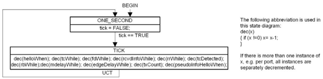
Figure 13-15—Port Timers state machine
The state machine uses tick (13.27), a signal set by an implementation-specific system clock function at one second intervals, to decrement the timer variables for the CIST and all MSTIs for the port. The state machine that uses a given timer variable is responsible for setting its initial value.
13.31 Port Receive state machine
The Port Receive state machine shall implement the function specified by the state diagram in Figure 13-16 and the attendant definitions in 13.25 through 13.29.
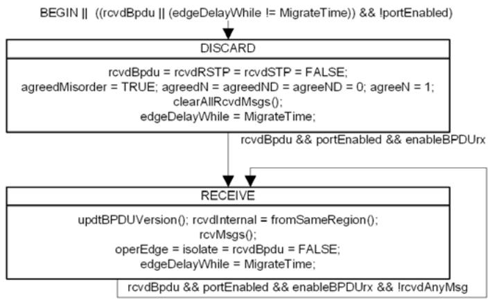
Figure 13-16—Port Receive state machine
This state machine receives and decodes validated BPDUs. The rcvdMsg flag is set for the CIST and for each MSTI supported by the receiving Bridge if the received BPDU is from the same MST or SPT Region. The next BPDU is not processed until all rcvdMsg flags have been cleared by the per-tree state machines.
NOTE—This standard does not specify or constrain the means used by the rcvMsgs() procedure to identify or extract per-tree information from a BPDU for processing by rcvInfo() in the Port Information Machine RECEIVE state.
13.32 Port Protocol Migration state machine
The Port Protocol Migration state machine shall implement the function specified by the state diagram in Figure 13-17 and the attendant definitions in 13.25 through 13.29.
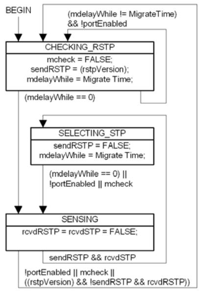
Figure 13-17—Port Protocol Migration state machine
13.33 Bridge Detection state machine
The Bridge Detection state machine shall implement the function specified by the state diagram in Figure 13-18 and the attendant definitions in 13.25 through 13.29.
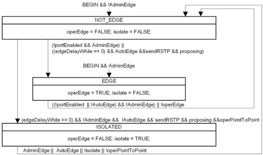
Figure 13-18—Bridge Detection state machine
13.34 Port Transmit state machine
The Port Transmit state machine shall implement the function specified by the state diagram in Figure 13-19 and the attendant definitions in 13.25 through 13.29.
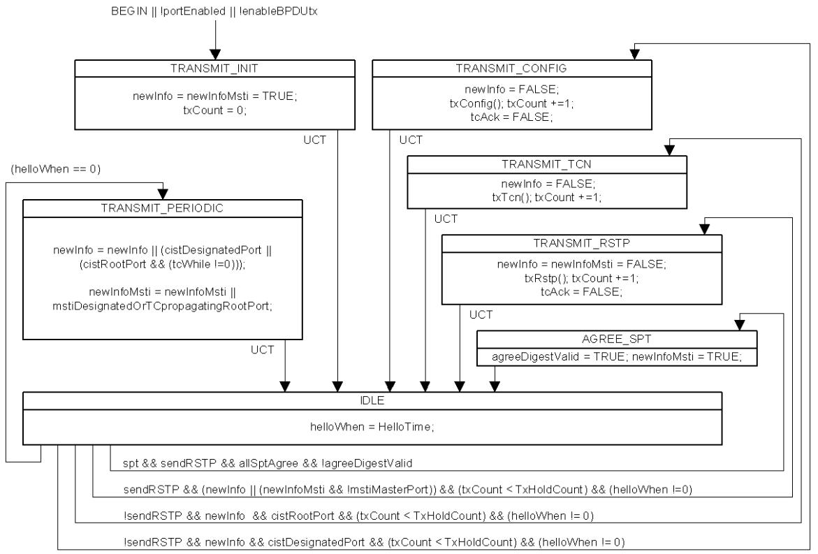
Alltransitions,except UCT,are qualified by "&& allTransmitReady"
Figure 13-19—Port Transmit state machine
This state machine is responsible for transmitting BPDUs. It also determines when the Agreement Digest in SPT BPDUs can be updated, and prompts transmission when that has been done.
NOTE 1—Any single received BPDU that changes the CIST Root Identifier, CIST External Root Path Cost, or CIST Regional Root associated with MSTIs should be processed entirely, or not at all, before encoding BPDUs for transmission.This recommendation minimizes the number of BPDUs to be transmitted following receipt of a BPDU with new information. It is not required for correctness and has not therefore been incorporated into the state machines.
NOTE 2—If a CIST state machine sets newInfo, this machine will ensure that a BPDU is transmitted conveying the new CIST information. If MST BPDUs can be transmitted through the port, this BPDU will also convey new MSTI information for all MSTIs. If a MSTI state machine sets newInfoMsti, and MST BPDUs can be transmitted through the port, this machine will ensure that a BPDU is transmitted conveying information for the CIST and all MSTIs. Separate newInfo and newInfoMsti variables are provided to avoid requiring useless transmission of a BPDU through a port that can only transmit STP BPDUs (as required by the Force Protocol Version parameter or Port Protocol Migration machine) following a change in MSTI information without any change to the CIST.
13.35 Port Information state machine
The Port Information state machine for each tree shall implement the function specified by the state diagram in Figure 13-20 and the attendant definitions in 13.25 through 13.29.
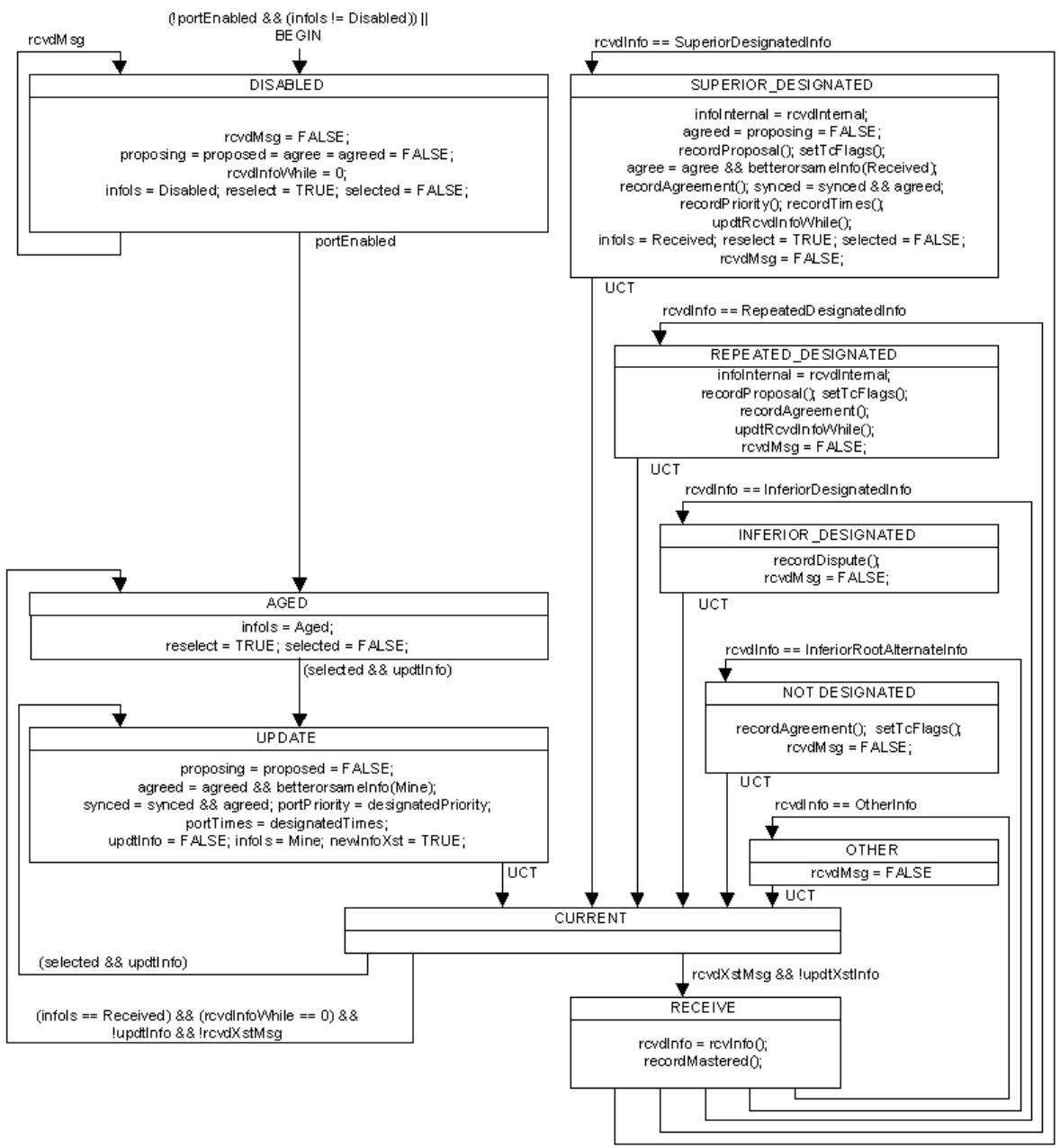
Figure 13-20—Port Information state machine
This state machine is responsible for recording the spanning tree information currently in use by the CIST or a given MSTI for a given port, ageing that information out if it was derived from an incoming BPDU, and recording the origin of the information in the infoIs variable. The selected variable is cleared and reselect set to signal to the Port Role Selection machine that port roles need to be recomputed. The infoIs and portPriority variables from all ports are used in that computation and, together with portTimes, determine new values of designatedPriority and designatedTimes. The selected variable is set by the Port Role Selection machine once the computation is complete.
13.36 Port Role Selection state machine
The Port Role Selection state machine shall implement the function specified by the state diagram in Figure 13-21 and the attendant definitions in 13.25 through 13.29.
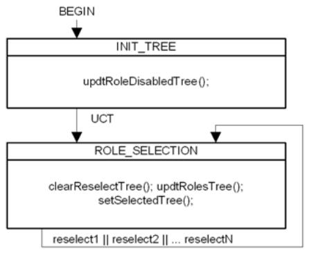
Figure 13-21—Port Role Selection state machine
When ISIS-SPB finishes a link state calculation, it clears the selected variable for each port for each SPT before updating agreementDigest (13.26.1) for the Bridge component, the root priority vector (rootPortId, rootPriority—13.26.9, 13.26.10) for each SPT and the selectedRole (13.12, 13.27.68), designated priority vector (designatedPriority—13.27.20), and neighbourPriority for each port for each SPT. ISIS-SPB then sets reselect for each SPT.
13.37 Port Role Transitions state machine
The Port Role Transitions state machine shall implement the function specified by the state diagram in the following figures:
a) Part 1: Figure 13-22 for both the initialization of this state machine and the states associated with the DisabledPort role; and
b) Part 2: Figure 13-23 for the states associated with the MasterPort role; and
c) Part 3: Figure 13-24 for the states associated with the RootPort role; and
d) Part 4: Figure 13-25 for the states associated with the DesignatedPort role; and
e) Part 5: Figure 13-26 for the states associated with the AlternatePort and BackupPort roles;
and the attendant definitions in 13.25 through 13.29.
As Figure 13-22, Figure 13-23, Figure 13-24, Figure 13-25, and Figure 13-26 are component parts of the same state machine, the global transitions associated with these diagrams are possible exit transitions from the states shown in any of the diagrams.
Figure 13-22 and Figure 13-26 show the Port Roles for ports that do not form part of the active topology of the given tree.
Figure 13-23, Figure 13-24, and Figure 13-25 show the Port Roles that form part of the active topology.
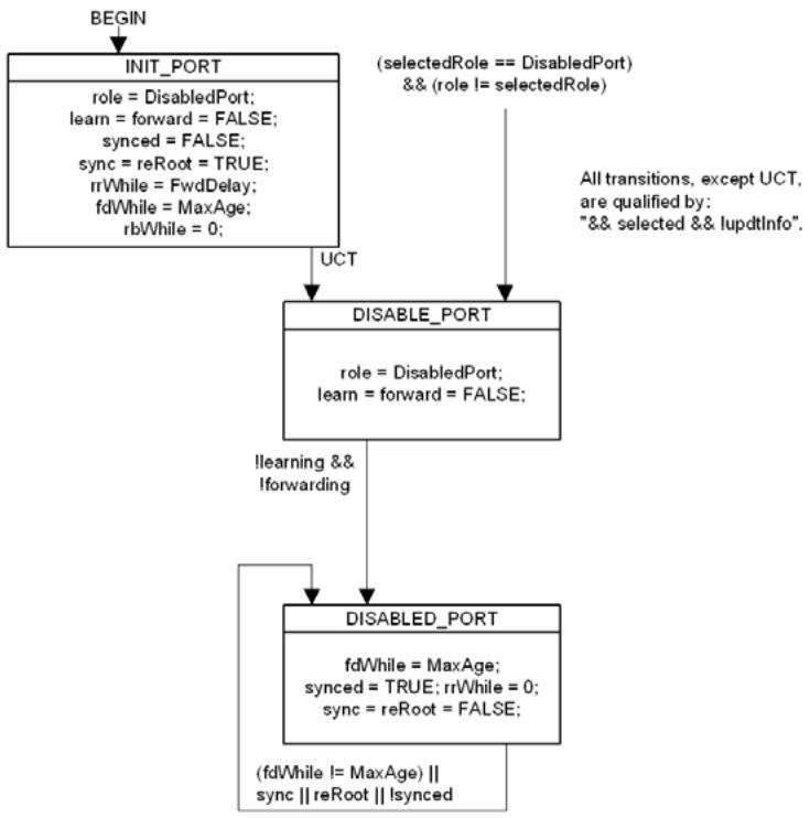
Figure 13-22—Disabled Port role transitions
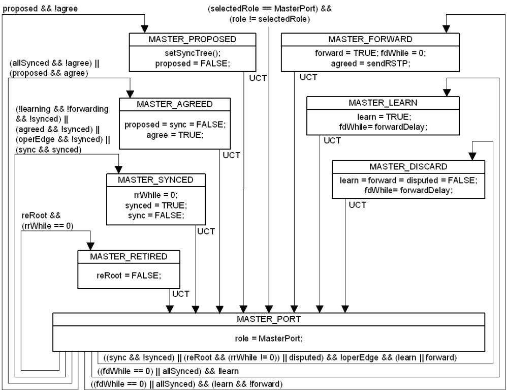
Alltransitions,except UCT,arequalified by "&&selected && lupdtlnfo".
Figure 13-23—Port Role Transitions state machine—MasterPort
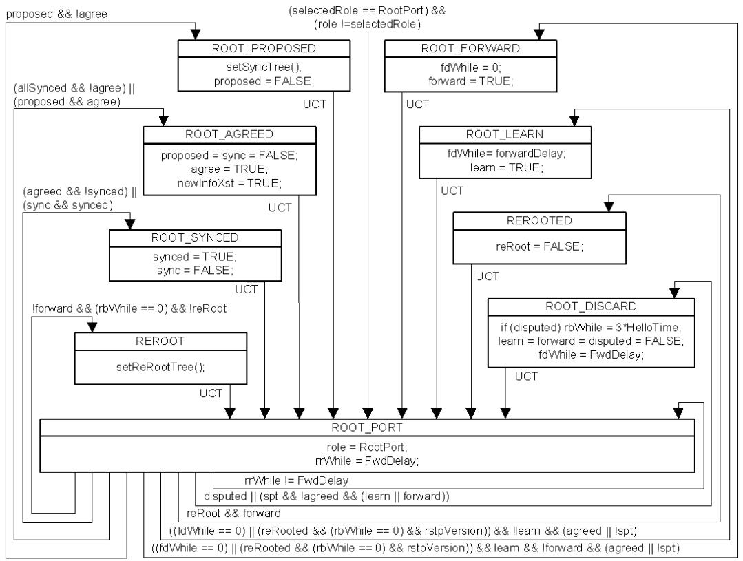
Alltransitions,except UCT,are qualified by "&& selected && lupdtinfo".
Figure 13-24—Port Role Transitions state machine—RootPort
All transitions,except UCT,are qualified by "&& selected && lupdtlnfo"
Figure 13-25—Port Role Transitions state machine—DesignatedPort
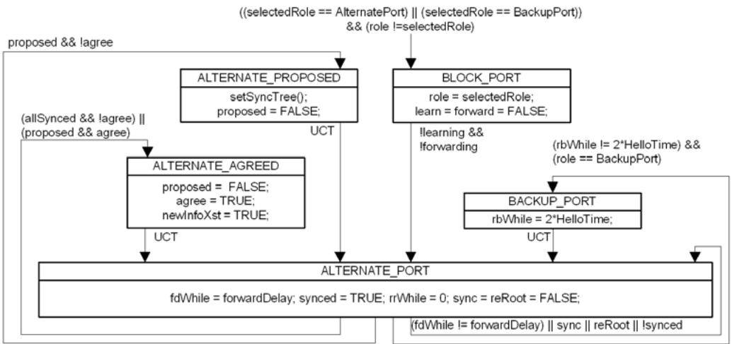
Alltransitions,except UCT,are qualified by "&& selected && lupdtlnfo".
Figure 13-26—Port Role Transitions state machine—AlternatePort and BackupPort
13.38 Port State Transition state machine
The Port State Transition state machine shall implement the function specified by the state diagram in Figure 13-27 and the attendant definitions in 13.25 through 13.29.
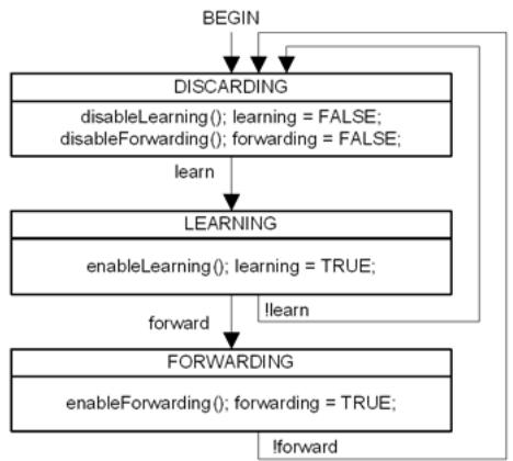
Figure 13-27—Port State Transition state machine
NOTE—A small system-dependent delay may occur on each of the transitions shown in the referenced state machine.
This state machine operates independently of the type of tree (CIST, MSTI, or SPT) and whether backbone bridging is being supported. However, the way in which the Bridge supports the learn and forward variables and the disableForwarding(), disableLearning(), enableForwarding(), and enableLearning() procedures are supported does vary (see 8.4, 8.6, 8.6.1). The forwarding and learning variables provide implementationindependent reporting of the current state.
13.38.1 Port State transitions for the CIST and MSTIs
The CIST and each MSTI are always supported by an explicit Port State, enforced by Bridge’s implementation of the Forwarding Process, and the procedures prompt that implementation to take the necessary action to forward and/or learn from received frames (as requested).
13.38.2 Port State transitions for SPTs
The enableLearning() and disableLearning() procedures return without taking an action: for SPBV mode learning does not occur until forwarding is enabled (8.6.1); for SPBM mode the Learning Process (8.7) neither creates or deletes Dynamic Filtering Entries.
When a VLAN is supported by an SPT Bridge using SPBV mode, a Dynamic VLAN Registration Entry is created for each SPVID and Enable Ingress Filtering (8.6.2) enabled on each port. Connectivity is provided, and loops prevented, by adding and removing ports from the Dynamic VLAN Registration Entry (27.13).
The enableForwarding() procedure adds the port to the Dynamic VLAN Registration Entry for each SPVID that is associated with the SPT (provided the VLAN topology extends through the port, see 27.13). Similarly disableForwarding() removes the port from the registration entry.
When frames with a given VID are supported by SPBM mode, MAC address-based ingress filtering is used to discard a received frame if there is no corresponding Dynamic Filtering Entry (8.8, 8.6.1, 27.14) for that VID and the frame’s source MAC address with the receiving port in the Port Map.
ISIS-SPB identifies the port that provides the shortest path to a given Bridge: this is the Root Port for the SPT rooted at that Bridge. The individual MAC addresses (there can be more than one) known to ISIS-SPB as identifying sources for which that given Bridge first transmits frames within the SPT Region (entering the region from an attached Bridge or station, or from a protocol entity within the Bridge) or as identifying destinations for which that Bridge is the last recipient within the region (delivering frames to an attached Bridge or station, or to a protocol entity within the Bridge) are associated with that Root Port. If loop mitigation (6.5.4.2) is used for unicast frames, a Dynamic Filtering Entry is created for those addresses and VID, permitting forwarding through that port and no others, without reference to the state machines specified in this clause (Clause 13), and the setting or clearing of the forward variable for any port. The enableForwarding() procedure creates or modifies these Dynamic Filtering Entries, so that forwarding to and from a given port is permitted, if and only if loop prevention (6.5.4.1) is used for both unicast and multicast frames and the port’s role is RootPort, and has no effect otherwise. Similarly if loop prevention is being used, disableForwarding() modifies or removes any existing Dynamic Filtering Entry so that forwarding to or from the port is not permitted.
NOTE—The Port Role Transition machine allows an SPT to transition a Root Port to Discarding in support of enableForwarding() and disableForwarding() as specified in this subclause (13.38.2). The need to specify that transition could have been avoided by specifying that the Dynamic Filtering Entry would only permit forwarding through a given port if forward was TRUE for the port for every other SPT for which it was a Designated Port. While equivalent, such a specification approach would have been obscure and many implementors would have failed to spot the way to avoid checking variables for all SPTs when processing a change for a single tree.
An SPT Bridge using SPBM mode uses source-specific multicast addresses, so that the destination address alone can be used to identify the SPT (Clause 27) on egress, and a Static Filtering Entry (8.8.1) is created for that multicast address and the B-VIDs supported by the SPT. If enableForwarding() is invoked for a Designated Port, the Static Filtering Entry’s control element for that port is updated to specify that frames should be Forwarded through the port. The control element is modified to specify Filtered if enableForwarding() is invoked and the port’s role is not Designated Port, or if disabledForwarding() is used.
13.39 Topology Change state machine
The Topology Change state machine for each tree shall implement the function specified by the state diagram in Figure 13-28 and the attendant definitions in 13.25 through 13.29.
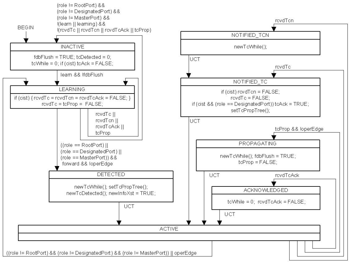
Figure 13-28—Topology Change state machine
NOTE—MRP (Clause 10) uses the tcDetected variable maintained by this state machine.
13.40 Layer 2 Gateway Port Receive state machine
If implemented, the Layer 2 Gateway Port state machine for each port shall implement the function specified by the state diagram in Figure 13-29 and the attendant definitions in 13.25 through 13.29.
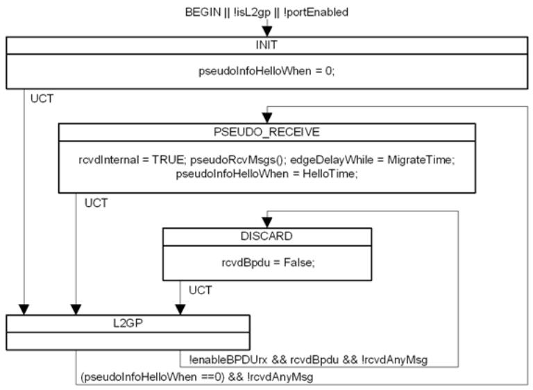
Figure 13-29—L2 Gateway Port Receive state machine
NOTE—The functionality provided by this state machine is discussed in 13.20, 25.9.2, 26.4.3, and 13.29.11.
13.41 CEP spanning tree operation
This subclause specifies the operation of the Spanning Tree Protocol Entity within a C-VLAN component that supports a CEP (Figure 15-4) of a Provider Edge Bridge. The CEP and each PEP are treated as separate Bridge Ports by the spanning tree protocol.
If the C-VLAN component connects to the S-VLAN component with a single PEP, and the associated service instance supports no more than two customer interfaces, then all frames (including ST BPDUs) addressed to the Bridge Group Address may be relayed between the two ports of the C-VLAN component without modification. Otherwise, the Spanning Tree Protocol Entity shall execute RSTP, as modified by the provisions of this subclause (13.41).
The RSTP enhancements specified do not reduce PBN connectivity between CEPs to a single spanning tree of service instances but ensure that connectivity for frames assigned to any given C-VLAN is loop-free. In this respect, the C-VLAN component’s spanning tree protocol operation is equivalent to, but simpler to manage than, the operation of MSTP.
13.41.1 PEP operPointToPointMAC and operEdge
The value of the adminPointToPointMAC parameter for a PEP is always Auto, and no management control over its setting is provided. The value of the operPointToPointMAC parameter, used by the RSTP state machines, shall be TRUE if the service instance corresponding to the PEP connects at most two customer interfaces, and FALSE otherwise.
The value of the AdminEdge, AutoEdge, and operEdge parameters for a PEP are always FALSE, TRUE, and FALSE, respectively. No management control over their setting is provided.
13.41.2 updtRolesTree()
The spanning tree priority vectors timer values are calculated, and the port role for each port, its port priority vector, and timer information updated as specified in 13.29.34, with one exception. If selectedRole was to be set to AlternatePort, the port is a PEP, and the root priority vector was derived from another PEP, then the selectedRole shall be set to Root Port.
NOTE—The effect of this enhancement is to allow the C-VLAN component to have multiple Root Ports (just as if separate per S-VLAN trees were being provided), if they are all PEPs. As the C-VLAN component assigns each frame to a single C-VLAN and maps any given C-VLAN to and from at most one PEP, no loop is created.
13.41.3 setReRootTree(), setSyncTree(), setTcPropTree()
The setReRootTree() and setSyncTree() procedures specified in 13.29.21 and 13.29.23 set the reRoot and sync variables for all ports of the Bridge, and the setTcPropTree() as specified in 13.29.25 sets the tcProp variable for all ports other than the port that invoked the procedure. If the port invoking the procedure is a CEP, then this behavior is unchanged; if it is a PEP, then the behavior of each procedure shall be as follows:
The setReRootTree() procedure sets reRoot for the port invoking the procedure and for the CEP.
— The setSyncTree() procedure sets sync for the port invoking the procedure and for the CEP.
The setTcPropTree() procedure sets tcProp for the CEP.
13.41.4 allSynced, reRooted
RSTP specifies a single value of the allSynced and reRooted state machine conditions for all Bridge Ports. This specification requires an independent value of each of these conditions for each port of the C-VLAN component. If that port is the CEP, then allSynced shall be TRUE if and only if synced is TRUE for all PEPs, and reRooted shall be TRUE if and only if rrWhile is zero for all PEPs. If the port for which the condition is being evaluated is a PEP, then allSynced shall take the value of synced for the CEP, and reRooted shall be TRUE if and only if rrWhile is zero for the CEP.
13.41.5 Configuration parameters
All configuration parameters for RSTP should be set to their recommended defaults, with the exception of the following, which are chosen to minimize the chance of interfering with the customer’s configuration (e.g., by the C-VLAN component becoming the root of the customer spanning tree), as follows:
a) The Bridge Priority (13.18, Table 13-3, 13.26.2) should be set to 61 440. This sets the priority part of the Bridge Identifier (the most significant 4 bits) to hex F.
b) The following 12 bits (the Bridge Identifier system ID extension) should be set to hex FFF.
c) The Port Priority (13.18, Table 13-3, 13.27.47) should be set to 32. This sets the priority part of the Port Identifier (the most significant 4 bits) to hex 2, a higher priority than the default (128, or hex 8).
d) The Port Path Cost values for PEPs should be set to 128.
All BPDUs generated by the Spanning Tree Protocol Entity within a C-VLAN component use the MAC address of the CEP as a source address and as the Bridge address portion of the Bridge Identifier. For each internal PEP, the protocol uses the S-VID associated with the corresponding internal CNP on the S-VLAN component as a port number. For the CEP, the value 0xFFF is used as the port number.
13.42 Virtual Instance Port (VIP) spanning tree operation
This subclause specifies the operation of the Spanning Tree Protocol Entity within an I-component in a BEB. The CNPs and VIPs are treated as separate Bridge Ports by the spanning tree protocol.
If the I-component has a single CNP and a single VIP supported by a point-to-point backbone service instance, then all frames (including ST BPDUs) addressed to the Provider Bridge Group address may be relayed between the two ports of the I-component without modification. Otherwise, the Spanning Tree Protocol Entity shall execute RSTP, as modified by the provisions of this subclause.
The RSTP enhancements specified ensure that connectivity for frames assigned to any given S-VLAN is loop-free.
The parameters and functions of the RSTP used on the VIPs get the same values and functionality as defined for PEPs of a C-VLAN component as defined in 13.41. The Bridge Identifier Priority and system ID extension get the values specified in 13.41.5. These changes in RSTP ensure that no VIP is blocked due to the operation of RSTP and the I-component will never be elected as root.
NOTE—The effect of not blocking any VIP in the I-component (never set the port role alternate to a VIP) will not cause a loop since the I-component maps any given S-VID to at most one VIP.
14 Encoding of Bridge Protocol Data Units (BPDUs)
This clause specifies formats, and the encoding, decoding, and validation of BPDUs exchanged by protocol entities operating RSTP, MSTP, and other protocols enhancing or designed to interoperate with STP, RSTP, or MSTP (Clause 13).
Interoperability with STP, as specified in IEEE Std 802.1D, 1998 Edition [B9], and prior revisions, is provided as specified by the state machines and procedures in Clause 13 of this standard. Parameter type encodings for STP BPDUs are a subset of those used for RSTP, MSTP, and SPT BPDUs, and the fields encoded in STP Configuration BPDUs are a subset of those used in RST BPDUs.
The format of MST BPDUs is compatible with that specified for RST BPDUs, with the addition of fields to convey information for the IST and each MSTI, and is shown in Figure 14-1.
The format of SPT BPDUs comprises the fields specified for MST BPDUs, with the addition of fields that communicate the Agreement Number, Discarded Agreement Number, and Agreement Digest (13.17).
The Protocol Version Identifier encoded in all BPDUs serves to distinguish RST BPDUs, MST BPDUs, and SPT BPDUs. A BPDU Type is also encoded in all BPDUs, and distinguishes the Configuration and TCN BPDUs used by STP and by the spanning tree protocols specified in this standard when interoperating with STP implementations.
Figure 14-1 shows the overall format of RST, MST, SPT, and STP Configuration BPDUs. Figure 14-2 shows the format of STP TCN BPDUs.
14.1 BPDU Structure
14.1.1 Transmission and representation of octets
All BPDUs shall contain an integral number of octets. The octets in a BPDU are numbered starting from 1 and increasing in the order they are put into a Data Link Service Data Unit (DLSDU).When bit positions in an octet or a sequence of octets encode a number, the number is encoded as an unsigned binary numeral with bit positions in lower octet numbers having more significance. Within an octet the bits are numbered from 8 to 1, where 1 is the low-order bit. Where sequences of bits are represented, high order bits are shown to the left of lower order bits in the same octet, and bits in lower octet numbers are shown to the left of bits in higher octet numbers.
<table><tr><td></td><td>Octet</td></tr><tr><td>Protocol Identifier</td><td>1-2</td></tr><tr><td>Protocol Version Identifier</td><td>3</td></tr><tr><td>BPDU Type</td><td>4</td></tr><tr><td>CIST Flags</td><td>5</td></tr><tr><td>CIST Root Identifier</td><td>6-13</td></tr><tr><td>CIST External Path Cost</td><td>14-17</td></tr><tr><td>CIST Regional Root Identifier</td><td>18-25</td></tr><tr><td>CIST Port Identifier</td><td>26-27</td></tr><tr><td>Message Age</td><td>28-29</td></tr><tr><td>Max Age</td><td>30-31</td></tr><tr><td>Hello Time</td><td>32-33</td></tr><tr><td>Forward Delay</td><td>34-35</td></tr><tr><td>Version 1 Length = 0 (RST, MST, SPT BPDUs only)</td><td>36</td></tr><tr><td>Version 3 Length (MST, SPT BPDUs only)</td><td>37-38</td></tr><tr><td>MST Configuration Identifier</td><td>39-89</td></tr><tr><td>CIST Internal Root Path Cost</td><td>90-93</td></tr><tr><td>CIST Bridge Identifier</td><td>94-101</td></tr><tr><td>CIST Remaining Hops</td><td>102</td></tr><tr><td>MSTI Configuration Messages (may be absent)</td><td rowspan="4">103-39 + Version 3 Length(40 + Version 3 Length)-(41 + Version 3 Length)(42 + Version 3 Length)-(92 + Version 3 Length)(93 + Version 3 Length)-(41 + Version 3 Length+ Version 4 Length)</td></tr><tr><td>Version 4 Length (SPT BPDUs only)</td></tr><tr><td>Auxiliary MCID (SPT BPDUs only)</td></tr><tr><td>SPT Agreement Number, Discarded Agreement Number, Agreement Digest (SPT BPDUs only)</td></tr></table>
NOTE—BPDUs are encoded in LLC Type 1 frames following the DSAP, LSAP, and UI fields, so if that frame is received from directly an IEEE 802.3 MAC with the MAC addresses aligned on an even octet boundaries then the BPDU octet pairs 6 and 7, 14 and 15, 18 and 19, etc. will also be aligned on those boundaries.
Figure 14-1—RST, MST, SPT, and STP Configuration BPDU format
<table><tr><td></td><td>Octet</td></tr><tr><td>Protocol Identifier</td><td>1-2</td></tr><tr><td>Protocol Version Identifier</td><td>3</td></tr><tr><td>BPDU Type</td><td>4</td></tr></table>
Figure 14-2—STP TCN BPDU format
14.1.2 Common BPDU fields
A Protocol Identifier is encoded in the initial octets of all BPDUs. The single Protocol Identifier value of 0000 0000 0000 0000 identifies the spanning tree family of protocols (STP, RSTP, and MSTP) and BPDUs whose formats are compatible with
a) STP BPDUs, as specified in this clause and in IEEE Std 802.1D, 1998 Edition [B9]
b) RST BPDUs, as specified in this clause and Clause 9 of IEEE Std 802.1D-2004 [B10]
c) The BPDUs specified in IEEE Std 802.1G, now withdrawn
d) MST BPDUs, as specified in this clause
e) SPT BPDUs, as specified in this clause
NOTE—ISIS-SPB (Clause 27, Clause 28) sends and receives its own PDUs to support the distributed computation of symmetric SPTs.
A Protocol Version Identifier and BPDU Type are also encoded in all BPDUs.
14.2 Encoding of parameter types
14.2.1 Encoding of Protocol Identifiers
A Protocol Identifier shall be encoded in two octets.
14.2.2 Encoding of Protocol Version Identifiers
A Protocol Version Identifier shall be encoded in one octet. If two Protocol Version Identifiers are interpreted as unsigned binary numbers, the greater identifies the more recently defined Protocol Version.
14.2.3 Encoding of BPDU types
The type of the BPDU shall be encoded as a single octet. The bit pattern contained in the octet merely serves to distinguish the type; no ordering relationship between BPDUs of different types is implied.
14.2.4 Encoding of flags
A flag shall be encoded as a bit in a single octet. A flag is set if the bit takes the value 1. A number of flags may be encoded in a single octet. Bits in the octet that do not correspond to flags defined for the BPDU’s type are reset, i.e., shall take the value 0. No additional flags will be defined for a BPDU of given protocol version and type.
14.2.5 Encoding of Bridge Identifiers
A Bridge Identifier is a 64-bit unsigned integer. If two Bridge Identifiers are numerically compared, the lesser number denotes the Bridge of the better priority.
NOTE 1—Use of the terms “higher” and “lower” to describe both the relative numerical values and the relative priority of Spanning Tree information can cause confusion, as lesser numbers convey better priorities. In this clause and in Clause 13, relative numeric values are described as “least,” “lesser,” “equal,” and “greater,” and their comparisons as “less than,” “equal to,” or “greater than,” while relative spanning tree priorities are described as “best,” “better,” “the same,” “different,” and “worse” and their comparisons as “better than,” “the same as,” “different from,” and “worse than.” The terms “superior” and “inferior” describe comparisons not simply based on strict ordered comparison of priority components.
The most significant 4 bits of a Bridge Identifier comprise a settable priority component (13.20, 13.26.2), and can be modified for the CIST or for an MSTI independently of those for other MSTIs (or for the CIST), allowing the Bridge Identifier priority to be used to provide full and independent control over the configuration of each of those trees. Each SPT uses the same Bridge Identifier as the CIST, so SPT Bridge Identifiers are not separately encoded.
NOTE 2—To maintain management compatibility with implementations of revisions of this standard prior to the IEEE Std 802.1s-2002 amendment, and of IEEE Std 802.1D, 1998 Edition [B9] and prior revisions, the priority component is considered to be a 16-bit value for management purposes, but the values that it can be set to are restricted to only those values where the least significant 12 bits are zero (i.e., only the most significant 4 bits are settable).
The next most significant 12 bits of a Bridge Identifier (when encoded, the least significant 4 bits of the most significant octet plus the second most significant octet) comprise a locally assigned system ID extension, that provides a distinct Bridge Identifier for each MSTI. The CIST is identified by the system ID extension of zero. Each MSTI has a system ID extension value equal to its MSTID, a convention used to convey the MSTID for each MSTI parameter set in an MST BPDU.
The least significant 48 bits of the Bridge Identifier ensure its uniqueness and are derived from the globally unique Bridge Address (8.13.8) and are encoded in the third through eighth most significant octets of the encoded identifier according to the following procedure.
The third most significant octet is derived from the initial octet of the MAC address; the LSB of the octet (Bit 1) is assigned the value of the first bit of the Bridge Address, the next most significant bit is assigned the value of the second bit of the Bridge Address, and so on. The fourth through eighth octets are similarly assigned the values of the second to the sixth octets of the Bridge Address.
14.2.6 Encoding of External Root Path Cost and Internal Root Path Cost
The External Root Path Cost shall be encoded in four octets as a number of arbitrary cost units. The Internal Root Path Cost is similarly encoded in four octets. Subclause 13.18 recommends Port Path Cost values so that a common interpretation can be placed on path cost values, and reasonable spanning tree configurations obtained without explicit management.
NOTE—IEEE Std 802.1D-2004 [B10] refers to the External Root Path Cost as Root Path Cost and does not use Internal Root Path Cost.
14.2.7 Encoding of Port Identifiers
A Port Identifier is a 16-bit unsigned integer. If two Port Identifiers are numerically compared, the lesser number denotes the port of better priority. The most significant 4 bits of a Port Identifier is a settable priority component that permits the relative priority of ports on the same Bridge to be managed (13.27.46), and can be modified independently for the CIST and each MSTI. The less significant 12 bits is the Port Number expressed as an unsigned binary number, and is same for the CIST and all MSTIs. The value 0 is not used as a Port Number.
The Port Identifier for the CIST is encoded in two octets, comprising both the CIST’s priority component and the Port Number used for all spanning trees. The 4-bit priority component for each MSTI is encoded as a binary number, in the MSTI Configuration Message for that MSTI. Each SPT uses the same Port Identifier as the CIST, so SPT Port Identifiers are not separately encoded.
NOTE—IEEE Std 802.1D, 1998 Edition [B9], and prior revisions specified a priority component of 8 bits and a Port Number of 8 bits. To maintain management compatibility with prior implementations the priority component is still considered to be an 8-bit value, but its values are restricted to those where the least significant 4 bits are zero (and hence ignored in encoding).
14.2.8 Encoding of Timer Values
Timer Values shall be encoded in two octets, taken to represent an unsigned binary number multiplied by a unit of time of 1/256 of a second. This permits times in the range 0 to, but not including, 256 s to be represented.
14.2.9 Encoding of Port Role values
Port Role values shall be encoded in two consecutive flag bits, taken to represent an unsigned integer, as follows:
a) A value of 0 indicates Master Port;
b) A value of 1 indicates Alternate or Backup;
c) A value of 2 indicates Root;
d) A value of 3 indicates Designated.
NOTE—IEEE Std 802.1D-2004 [B10] identified the Port Role value of 0 as Unknown, as it not used as a CIST Port Role in transmitted BPDUs. A received BPDU with a CIST Port Role value of 0 is identified as a Configuration BPDU.
14.2.10 Encoding of Length Values
Version 1 Length Values are encoded in one octet, taken to represent an unsigned binary number. No further length values are encoded for Version 2. Length Values for Version 3 and 4 are encoded in two octets.
14.2.11 Encoding of Hop Counts
The number of remaining Hops parameter shall be encoded in a single octet.
14.3 Transmission of BPDUs
A Bridge Protocol Entity shall encode 0000 0000 0000 0000 in Octets 1 and 2 (conveying the Protocol Identifier), the remaining fields shall be encoded to convey an STP Configuration BPDU, an STP TCN BPDU, an RST BPDU, or an MST BDU as required by the Force Protocol Version parameter, the Port Protocol Migration state machine, and other protocol parameters, all as specified in Clause 13.
a) If transmission of an STP Configuration BPDU is required, the Protocol Version Identifier shall be 0, and the BPDU Type shall be 0000 0000.
b) If transmission of an STP TCN BPDU is required, the Protocol Version Identifier shall be 0, and the BPDU Type shall be 1000 0000.
c) If transmission of an RST BPDU is required, the Protocol Version Identifier shall be 2, and the BPDU Type shall be 0000 0010.
d) If transmission of an MST BPDU is required, the Protocol Version Identifier shall be 3, and the BPDU Type shall be 0000 0010.
e) If transmission of an SPT BPDU is required, the Protocol Version Identifier shall be 4, and the BPDU Type shall be 0000 0010.
The remaining parameters for STP Configuration, RST, MST, and SPT BPDUs shall be encoded as specified below (14.4).
14.4 Encoding and decoding of STP Configuration, RST, MST, and SPT BPDUs
STP Configuration, RST, MST, and SPT BPDU protocol parameters are encoded for transmission, and decoded, checked or ignored on receipt as follows:
a) Bit 1 of Octet 5 conveys the CIST Topology Change flag.
b) Bit 2 of Octet 5 conveys the CIST Proposal flag in RST, MST, and SPT BPDUs. It is unused in STP Configuration BPDUs, and shall be transmitted as 0 and ignored on receipt.
c) Bits 3 and 4 of Octet 5 conveys the CIST Port Role in RST, MST, and SPT BPDUs. It is unused in STP Configuration BPDUs, and shall be transmitted as 0 and ignored on receipt.
d) Bit 5 of Octet 5 conveys the CIST Learning flag in RST, MST, and SPT BPDUs. It is unused in STP Configuration BPDUs, and shall be transmitted as 0 and ignored on receipt.
e) Bit 6 of Octet 5 conveys the CIST Forwarding flag in RST, MST, and SPT BPDUs. It is unused in STP Configuration BPDUs, and shall be transmitted as 0 and ignored on receipt.
f) Bit 7 of Octet 5 conveys the CIST Agreement flag in RST, MST, and SPT BPDUs. It is unused in STP Configuration BPDUs, and shall be transmitted as 0 and ignored on receipt.
g) Bit 8 of Octet 5 conveys the Topology Change Acknowledge Flag in STP Configuration BPDUs. It is unused in RST, MST, and SPT BPDUs, and shall be transmitted as 0 and ignored on receipt.
h) Octets 6 through 13 convey the CIST Root Identifier.
NOTE 1—The 12-bit system ID extension component of the CIST Root Identifier can be received and subsequently transmitted as an arbitrary value, even in MST BPDUs, since the CIST Root may be an STP Bridge.
i) Octets 14 through 17 convey the CIST External Root Path Cost.
j) Octets 18 through 25 shall take the value of the CIST Regional Root Identifier when transmitted in RST and MST BPDUs, and the value of the CIST Bridge Identifier of the transmitting Bridge when transmitted in STP Configuration BPDUs. On receipt of an STP Configuration or RST BPDU both the CIST Regional Root Identifier and the CIST Designated Bridge Identifier shall be decoded from this field. On receipt of an MST BPDU the CIST Regional Root Identifier shall be decoded from this field.
k) Octets 26 and 27 convey the CIST Port Identifier of the transmitting Bridge Port.
l) Octets 28 and 29 convey the Message Age timer value.
m) Octets 30 and 31 convey the Max Age timer value.
n) Octets 32 and 33 convey the Hello Time timer value used by the transmitting Bridge Port.
o) Octets 34 and 35 convey the Forward Delay timer value.
No further octets shall be encoded in STP Configuration BPDUs. Additional octets in received BPDUs identified by the validation procedure (14.5) as STP Configuration BPDUs shall be ignored. The specification of encoding or decoding of further octets in this subclause refers only to RST, MST, and SPT BPDUs.
p) Octet 36 conveys the Version 1 Length. This shall be transmitted as 0. It is checked on receipt by the validation procedure (14.5).
No further octets shall be encoded in RST BPDUs. Additional octets in received BPDUs identified by the validation procedure (14.5) as RST BPDUs shall be ignored. The specification of encoding or decoding of further octets in this subclause refers only to MST and SPT BPDUs.
NOTE 2—As Version 2 does not specify any additional fields beyond the end of the Version 0 information, there is no Version 2 Length field specified in Version 2 of the protocol and therefore no need for a Version 2 length field here.
q) Octets 37 and 38 convey the Version 3 Length. Its value is the number of octets taken by the parameters that follow in the BPDU. It is checked on receipt by the validation procedure (14.5).
r) Octets 39 through 89 convey the elements of the MCID (13.8):
1) The Configuration Identifier Format Selector is encoded in octet 39 and shall take the value 0000 0000;
2) The Configuration Name is encoded in octets 40 through 71;
3) The Revision Level is encoded as a number in octets 72 through 73;
4) The Configuration Digest is encoded in octets 74 through 89.
s) Octets 90 through 93 convey the CIST Internal Root Path Cost.
t) Octets 94 through 101 convey the CIST Bridge Identifier of the transmitting Bridge. The 12-bit system ID extension component of the CIST Bridge Identifier shall be transmitted as 0. The behavior on receipt is unspecified if it is nonzero.
NOTE 3—The most significant 4 bits of the Bridge Identifier constitute the manageable priority component for each MSTI and are separately encoded in MSTI Configuration Messages in the BPDU.
u) Octet 102 encodes the value of remaining Hops for the CIST.
v) A sequence of zero or more, up to a maximum of 64, MSTI Configuration Messages follows, each encoded as specified in 14.4.1.
No further octets shall be encoded in MST Configuration BPDUs. Additional octets in received BPDUs identified by the validation procedure (14.5) as MST Configuration BPDUs shall be ignored. The specification of encoding or decoding of further octets in this subclause refers only to SPT BPDUs.
w) Octets 1 and 2 following the Version 3 information convey the Version 4 Length. Its value is the number of octets that follow the Version 4 Length in the BPDU, up to but not including octets added by subsequent revisions of this standard and associated with Versions 5 or greater. It is checked on receipt by the validation procedure (14.5).
x) Octets 1 through 51 following the Version 4 Length encode the Auxiliary MCID (if present) as follows:
1) The Configuration Identifier Format Selector is encoded in octet 1 and shall take the value 0000 0000;
2) The Configuration Name is encoded in octets 2 through 33;
3) The Revision Level is encoded as a number in octets 34 through 35;
4) The Configuration Digest is encoded in octets 36 through 51.
y) Octets 1 and 2 following the Auxiliary MCID are encoded (if present) as follows:
1) Bits 1 and 2 of Octet 1 convey the Agreement Number (13.27.11, 13.27.16).
2) Bits 3 and 4 of Octet 1 convey the Discarded Agreement Number (13.27.12, 13.27.17).
3) Bit 5 of Octet 1 conveys the Agreement Valid flag (13.27.7, 13.27.9).
4) Bit 6 of Octet 1 conveys the Restricted Role flag (13.27.63, 27.20).
5) Bits 7 through 8 of Octet 1 are unused, and shall be transmitted as 0 and ignored on receipt.
6) Octet 2 is unused, and shall be transmitted as 0 and ignored on receipt.
z) The remaining Octets following the Version 4 Length and covered by that length comprise the Agreement Digest (13.17.1, 28.4).
No further octets shall be encoded in BPDUs. Additional octets in received BPDUs shall be ignored.
14.4.1 MSTI Configuration Messages
A single instance of the following set of parameters is encoded for each MSTI supported by the transmitting Bridge.
a) Bits 1, 2, 3 and 4, 5, 6, 7, and 8, respectively, of Octet 1 convey the Topology Change flag, Proposal flag, Port Role, Learning flag, Forwarding flag, Agreement flag, and Master flag for this MSTI.
b) Octets 2 through 9 convey the Regional Root Identifier (13.27.20) as illustrated in Figure 14-3. This includes the value of the MSTID for this Configuration Message encoded in bits 4 through 1 of Octet 1, and bits 8 through 1 of Octet 2.
NOTE—The most significant 4 bits of each MSTI’s Regional Root Identifier constitute a manageable priority component.
c) Octets 10 through 13 convey the Internal Root Path Cost.
d) Bits 5 through 8 of Octet 14 convey the value of the Bridge Identifier Priority for this MSTI. Bits 1 through 4 of Octet 14 shall be transmitted as 0, and ignored on receipt.
e) Bits 5 through 8 of Octet 15 convey the value of the Port Identifier Priority for this MSTI. Bits 1 through 4 of Octet 15 shall be transmitted as 0, and ignored on receipt.
f) Octet 16 conveys the value of remainingHops for this MSTI (13.27.21).
<table><tr><td></td><td>Octet</td></tr><tr><td>MSTI Flags</td><td>1</td></tr><tr><td>MSTI Regional Root Identifier</td><td>2–9</td></tr><tr><td>MSTI Internal Root Path Cost</td><td>10–13</td></tr><tr><td>MSTI Bridge Priority</td><td>14</td></tr><tr><td>MSTI Port Priority</td><td>15</td></tr><tr><td>MSTI Remaining Hops</td><td>16</td></tr></table>
Figure 14-3—MSTI Configuration Message parameters and format
14.5 Validation of received BPDUs
The receiving protocol entity shall examine Octets 1 and 2 (conveying the Protocol Identifier), Octet 3 (conveying the Protocol Version Identifier encoded as a number), Octet 4 (conveying the BPDU Type) and the total length of the received BPDU (including the preceding fields, but none prior to the Protocol Identifier) to determine the further processing required as follows:
a) If the Protocol Identifier is 0000 0000 0000 0000, the BPDU Type is 0000 0000, and the BPDU contains 35 or more octets, it shall be decoded as an STP Configuration BPDU.
If the Protocol Identifier is 0000 0000 0000 0000, the BPDU Type is 1000 0000 (where bit 8 is shown at the left of the sequence), and the BPDU contains 4 or more octets, it shall be decoded as an STP TCN BPDU (9.3.2 of IEEE Std 802.1D-2004 [B10]).
c) If the Protocol Identifier is 0000 0000 0000 0000, the Protocol Version Identifier is 2, and the BPDU Type is 0000 0010 (where bit 8 is shown at the left of the sequence), and the BPDU contains 36 or more octets, it shall be decoded as an RST BPDU.
d) If the Protocol Identifier is 0000 0000 0000 0000, the Protocol Version Identifier is 3 or greater, the BPDU Type is 0000 0010, the Bridge is configured as an MST Bridge or an SPT Bridge or according to a future revision of this standard that intends to provide interoperability with prior revisions, and the BPDU:
1) Contains 35 or more but less than 103 octets; or
2) Contains a Version 1 Length that is not 0; or
3) Contains a Version 3 length that does not represent an integral number, from 0 to 64 inclusive, of MSTI Configuration Messages, it shall be decoded as an RST BPDU.
e) If the Protocol Identifier is 0000 0000 0000 0000, the Protocol Version Identifier is 3 or greater and the Bridge is configured as an MST Bridge or the Protocol Version Identifier is 3 and the Bridge is configured as an SPT Bridge or according to a future revision of this standard that intends to provide interoperability with prior revisions, the BPDU Type is 0000 0010, and the BPDU:
1) Contains 102 or more octets; and
2) Contains a Version 1 Length of 0; and
3) Contains a Version 3 length representing an integral number, from 0 to 64 inclusive, of MSTI Configuration Messages, it shall be decoded as an MST BPDU.
f) If the Protocol Identifier is 0000 0000 0000 0000, the Protocol Version Identifier is 3 or greater, the BPDU Type is 0000 0010, the Bridge is configured as an SPT Bridge or according to a future revision of this standard that intends to provide interoperability with prior revisions, and the BPDU:
1) Contains 102 or more octets; and
2) Contains a Version 1 Length of 0; and
3) Contains a Version 3 length representing an integral number, from 0 to 64 inclusive, of MSTI Configuration Messages; and
4) Is not a well-formed an SPT BPDU, i.e.,
i) Contains less than 6 octets following the octets specified by the Version 3 length;
ii) Has a Version 4 length that is less than 55;
iii) Does not contain an MCID Format Selector of 1,
it shall be decoded as an MST BPDU.
g) If the Protocol Identifier is 0000 0000 0000 0000, the Protocol Version Identifier is 4 or greater, the BPDU Type is 0000 0010, the Bridge is configured as an MST Bridge or an SPT Bridge or according to a future revision of this standard that intends to provide interoperability with prior revisions, and the BPDU:
1) Contains 106 or more octets; and
2) Contains a Version 1 Length of 0; and
Contains a Version 3 length representing an integral number, from 0 to 64 inclusive, of MSTI Configuration Messages; and
4) Is a well-formed an SPT BPDU, i.e., contains
i) At least 6 octets following the octets specified by the Version 3 length
ii) A Version 4 length of 55 or greater
iii) An MCID Format Selector of 1,
it shall be decoded as an SPT BPDU.
h) Otherwise, the BPDU shall be discarded and not processed.
NOTE 1—The LLC LSAP that identifies BPDUs is reserved for standard protocols, no other protocols using that LSAP have been standardized though they may be at some future time. At that time, BPDUs with different PIDs may be processed according to the rules of those protocols but will still be discarded from the point of view of MSTP.
NOTE 2—These validation rules do not contain a loopback check of the form specified for use with STP Configuration BPDUs in 9.3.4 of IEEE Std 802.1D-2004 [B10].
14.6 Validation and interoperability
The validation rules above (14.5) follow a consistent general approach that allows future version enhancements to be made while retaining backwards compatibility. In particular, tests (a) and (b) in 14.5 above do not check the Protocol Version Identifier.
In general, for an implementation that supports version A of a given protocol, a received PDU of a given type that carries a protocol version number B is interpreted as follows:
a) Where B is greater than or equal to A, the PDU shall be interpreted as if it carried the supported version number, A. Specifically:
1) All PDU types, parameters, and flags that are defined in version A shall be interpreted in the manner specified for version A of the protocol for the given BPDU type.
2) All PDU types, parameters, and flags that are undefined in version A for the given BPDU type shall be ignored.
3) All octets that appear in the PDU beyond the largest numbered octet defined for version A for the given BPDU type shall be ignored.
b) Where B is less than A, the PDU shall be interpreted as specified for the version number, B, carried in the BPDU. Specifically:
1) All PDU parameters and flags shall be interpreted in the manner specified for version B of the protocol for the given PDU type.
2) All PDU parameters and flags that are undefined in version B for the given BPDU type shall be ignored.
3) All octets that appear in the PDU beyond the largest numbered octet defined for version B for the given BPDU type shall be ignored.
NOTE—In other words, if the protocol version implemented differs from the protocol version number carried in the PDU, then only those PDU types, parameters, and flags that are specified within the lesser numbered protocol version are interpreted by the implementation (in accordance with the lesser numbered protocol version’s specification), and no attempt is made to interpret any additional PDU types, parameters, and flags that may be specified within the greater numbered protocol version. In the specific case of STP (version 0) and RSTP (version 2), as there is only a single RST BPDU type defined in version 2, and as the RST BPDU type is undefined in version 0, a version 0 implementation will ignore all RST BPDUs. Version 2 implementations, however, recognize and process both version 0 and version 2 BPDUs. As version 2 makes no changes to the BPDU types defined for version 0 (and always transmits such BPDU types with 0 as the version identifier), version 0 BPDUs are always interpreted by version 2 implementations according to their version 0 definition.
15 Support of the MAC Service by PBNs
Provider Bridges interconnect the separate MACs of the IEEE 802 LANs that compose a PBN, relaying frames to provide connectivity between all LANs that provide customer interfaces for each service instance. The position of the Provider Bridge S-VLAN component bridging function within the MAC Sublayer is shown in Figure 15-1.
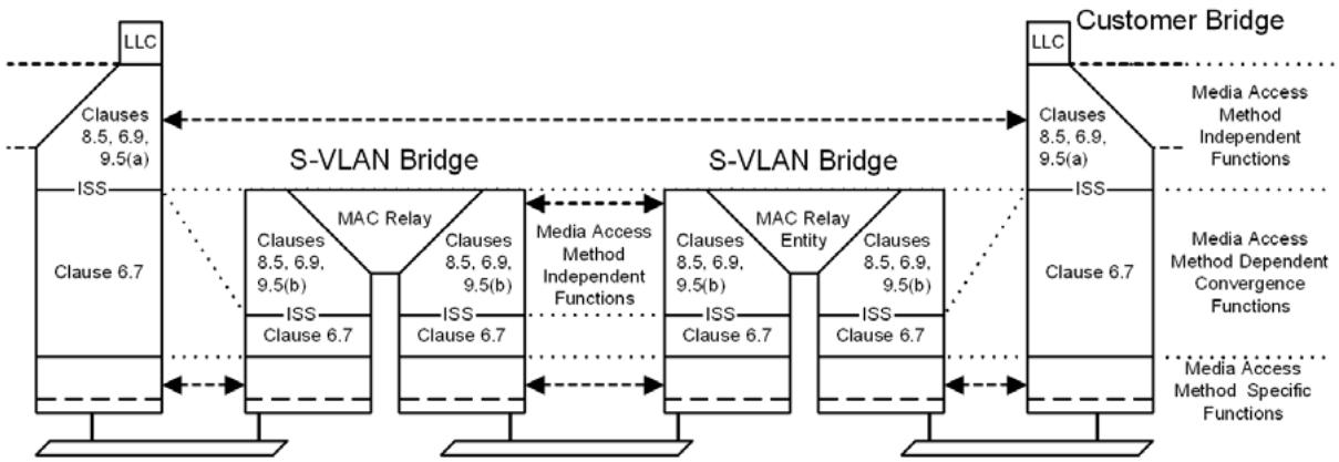
Figure 15-1—Internal organization of the MAC sublayer in a PBN
This clause discusses the following aspects of provisioning service instances on a PBN:
a) Service transparency
b) Customer service interfaces
c) Service instance segregation
d) Service instance selection and identification
e) Service priority selection
f) Service access protection
NOTE—In describing the MAC Service, this standard makes use of term “service” as defined by the OSI Reference Model (ISO/IEC 7498-1). In this sense, a service comprises a set of primitives and associated parameters, provided by one protocol layer in the architectural model to the protocol layer above, and the causal relationships between the primitives invoked by an upper layer protocol (ULP) entity in one system with those resulting indications to a peer entity in another system. The term “service” used by service providers, while including layering concepts, goes far beyond this formal definition, and commonly specifies some or all of the following: interfacing considerations across multiple protocol layers (including physical connectors, for example); selection of interface points; interfacing equipment; QoS guarantees and measurement methods; charging methods and responsibilities; connectivity verification and other management tools; and regulatory issues. Many of these aspects lie outside the scope of this standard; the reader is referred to the bibliography in Annex Q, which includes references to completed and ongoing work in the MEF (Metro Ethernet Forum) and the ITU.
15.1 Service transparency
The operation of Provider Bridges and the networks they compose is, by design, largely transparent to Customer Bridges and CBNs as illustrated by Figure 15-1.
The service provided by Provider Bridges is transparent to the use of the MAC Service by end stations attached to the CBNs and transparent to the operation of media access method-independent functions by Customer Bridges.
The service is not transparent to the operation of media access method-dependent convergence functions, specified in IEEE Std 802.1AC, or to the operation of the media access method-specific functions specified by standards for each media access method. Media access method-dependent and -specific functions operate between Bridges, whether Customer Bridges or Provider Bridges, attached to the same LAN. Where these functions make use of standard group MAC addresses, those addresses are included in the Reserved Addresses that are always filtered by Customer Bridges (Table 8-1) and by Provider Bridges (Table 8-2).
Frames transmitted and received by media access method-independent functions particular to PBN operation are not forwarded by Customer Bridges between provider networks. Where these frames are addressed using standard group MAC addresses, those addresses are included in the Reserved Addresses that are always filtered by Customer Bridges (Table 8-1). In addition, such frames may be filtered from PEPs.
15.2 Customer service interfaces
A service provider can offer a customer one or more types of service interfaces, each providing different capabilities for service selection, priority selection, and service access protection (15.8, 15.9, and 15.10). Some service interfaces are provided by the service provider operating systems that include C-VLAN components, or by customer operating systems that include S-VLAN components. In all cases, segregation of different service instances is achieved at an interface wholly under the control of the service provider by authentication and authorization of the attached customer systems, and by verification of customer provided parameters that provide service instance selection.
NOTE—The term “service access protection” describes provision of service access over multiple access LANs with redundancy and rapid failover in case of failure of an access LAN or attached equipment.
Access to a given service instance can be provided through different types of customer interface.
15.3 Port-based service interface
The customer service interfaces that can be provided by a provider network are specified by reference to a CNP provided by the S-VLAN component of a Provider Bridge. The CNP provides a single service instance, as illustrated in Figure 15-2 and Figure 15-3. The attached customer system can be a Bridge, a router, or an end station.
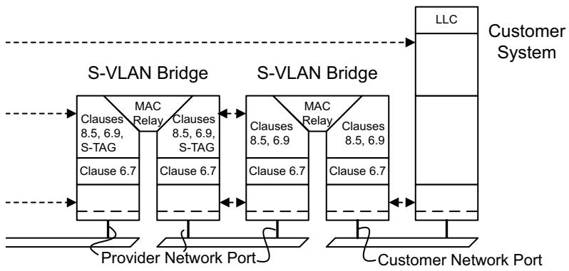
Figure 15-2—Port-based service interface to a PBN
This interface is Port-based; i.e., customers select and identify different service instances by associating each with a different CNP. Frames transmitted to a CNP by a C-VLAN aware customer system do not include an S-VID but can be priority-tagged with an S-TAG (6.13).
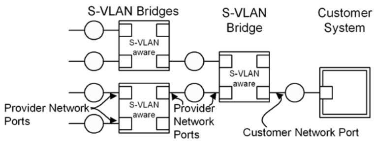
Figure 15-3—Port-based service interface to a PBN
NOTE—The terms “Customer Network Port,” “Customer Edge Port,” “Provider Network Port,” and “Provider Edge Port,” do not refer to the ownership of equipment, or necessarily to differently implemented Ports, but to Ports that are configured to fulfil the requirements of precise roles within a structured provider network design. These requirements are described in 15.6 through 15.10 and in Clause 16. All “Network” Ports are part of S-VLAN components, and all “Edge” Ports are part of C-VLAN components, whereas all “Customer” Ports receive data from a single customer inbound to the network and transmit data outbound from the network to a single customer. See Clause 3 for definitions.
15.4 C-tagged service interface
A C-tagged service interface can be provided by a Provider Edge Bridge comprising one or more C-VLAN components attached to Port-based service interfaces provided by a single S-VLAN component, as illustrated by Figure 15-4 and Figure 15-5.
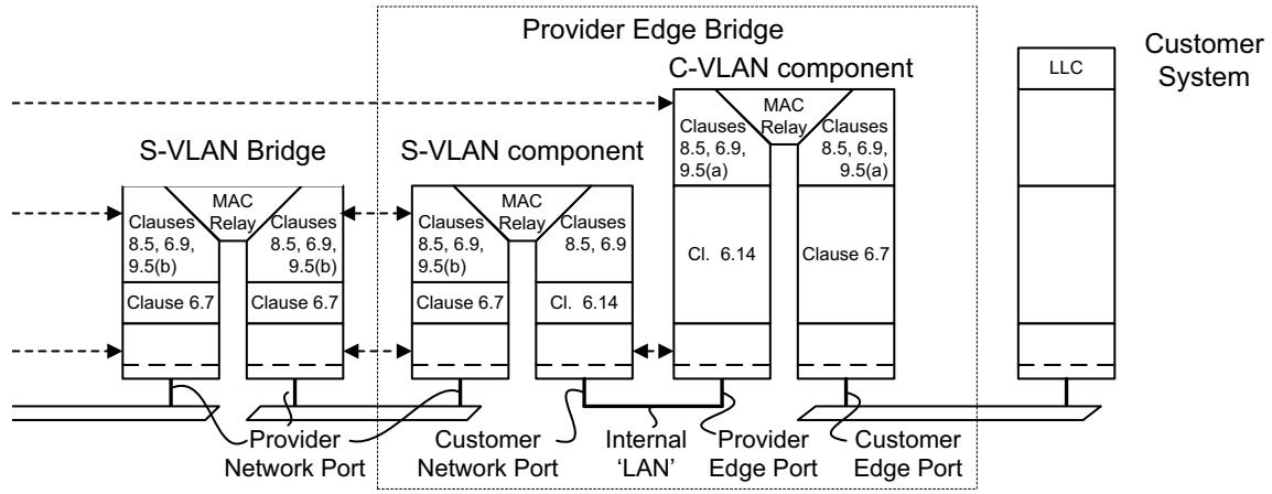
Figure 15-4—C-tagged service interface to a PBN
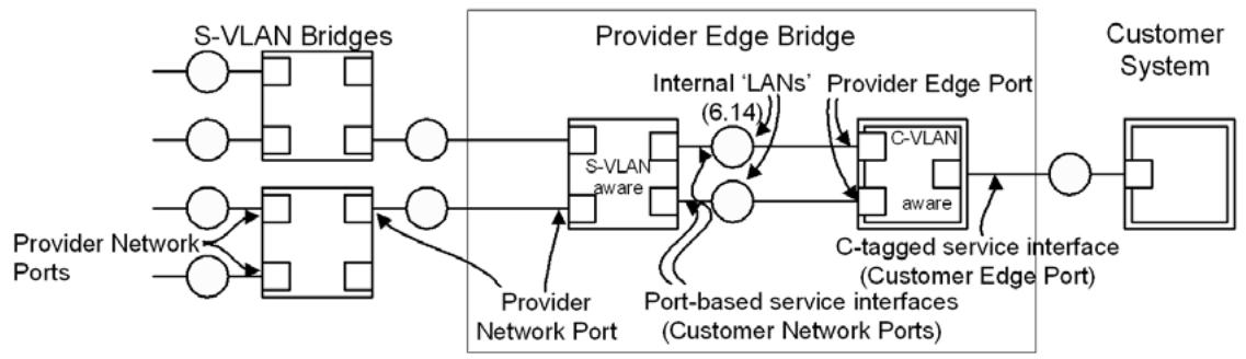
Figure 15-5—C-tagged service interface to a PBN
The C-tagged service interface allows service instance selection and identification by C-VID. Each frame from the customer system is assigned to a C-VLAN and presented at zero or one internal Port-based service interfaces, each supporting a single service instance that the customer desires to carry that C-VLAN.
NOTE—The restriction that each C-VLAN map to a single service instance allows the customer equipment receiving frames to correctly identify the service instance used, supports mechanisms that guard against accidental creation of data loops, and prevents configuration of the C-VLAN component to create a multi-point service from point-to-point service instances. The service provider can offer a multi-point service through appropriate configuration of the S-VLAN component.
Similarly frames from the provider network are assigned to an internal interface or “LAN” on the basis of the S-VID. As each internal interface supports a single service instance, no S-TAG is used at this interface. If multiple C-VLANs are supported by this service instance, the frames will have C-TAGs with the possible exception of frames for a single C-VLAN. The C-VLAN component applies a PVID to untagged frames received on each internal “LAN,” allowing full control over the delivery of frames for each C-VLAN through the CEP.
Each Provider Edge Bridge can support multiple CEPs for the same customer or for multiple customers. Each CEP is supported by a dedicated C-VLAN component as illustrated in Figure 15-6.
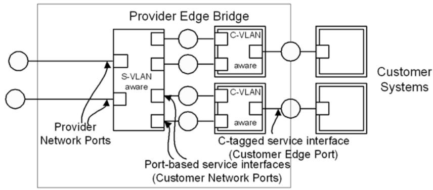
Figure 15-6—Customer Edge Ports (CEPs)
15.5 S-tagged service interface
An S-tagged service interface can be provided to an S-VLAN Bridge operated by a customer as illustrated by Figure 15-7 and Figure 15-8, or to a customer-operated Provider Edge Bridge that in turn provides C-tagged service interfaces within the customer’s own network as described in 15.4.
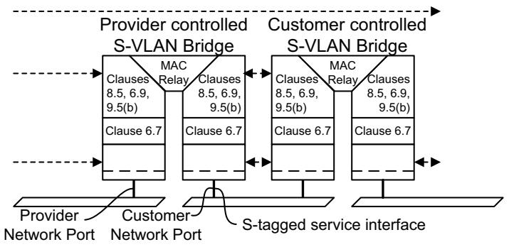
Figure 15-7—S-tagged service interface to a PBN
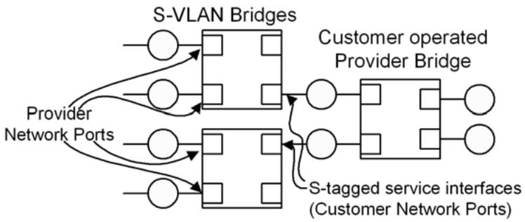
Figure 15-8—S-tagged interface to a PBN
15.6 Remote customer service interfaces (RCSIs)
An RCSI provides a C-tagged or Port-based service interface to a customer attached via an access PBN as depicted in Figure 16-2 (16.2). Multiple RCSIs can be provided over a LAN interconnecting two PBNs through the use of a Port-mapping S-VLAN component as shown in Figure 15-2. The Port-mapping S-VLAN component has one external port (RCAP) and one or more internal Ports (PAPs) that each support one RCSI. The Port-mapping S-VLAN component also can have an internal PNP for service instances that do not require an RCSI.
The Port-mapping S-VLAN component is configured to associate a unique S-VID with each PAP. Furthermore, each S-VID configured in the Port-mapping S-VLAN component has the RCAP and exactly one other Port in its member set. This ensures that each external service instance is mapped to only one internal port. See Figure 15-9
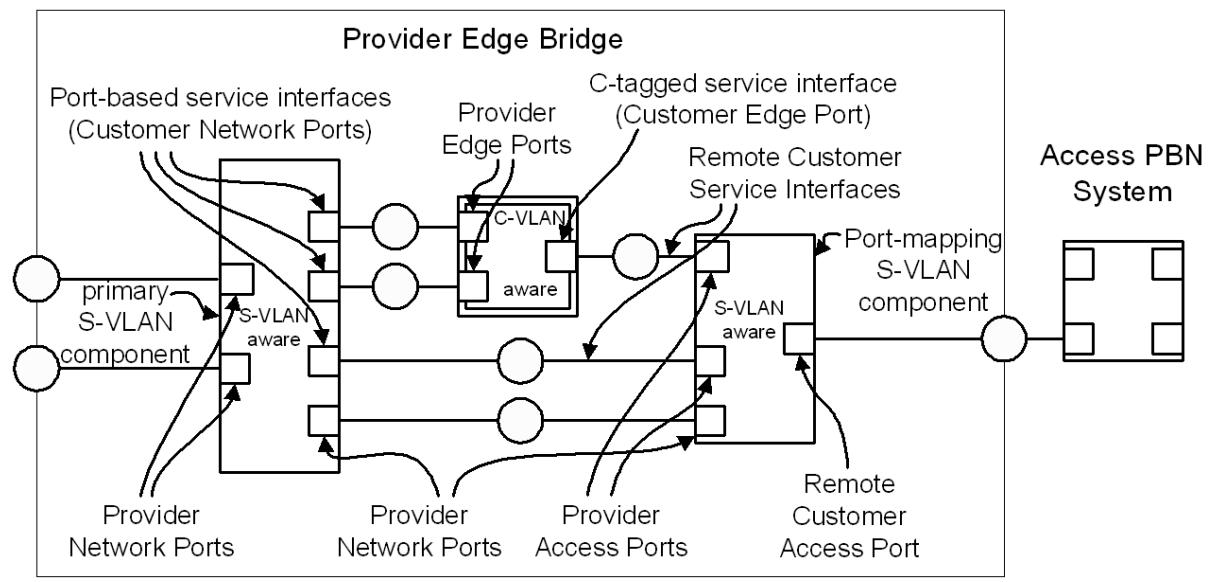
Figure 15-9—RCSIs to a PBN
Each RCSI supported by a RCAP is associated with a PAP connected via an internal LAN to either a CNP, providing a Port-based service interface (15.3), or a CEP, providing a C-tagged service interface (15.4). The external S-VID mapped to an RCSI identifies a service instance originating at a remote customer interface LAN attached to an access PBN (16.2). To provide separation between the external S-VID space used by the access PBN and the internal S-VID space for this PBN, frames on an RCSI do not carry an S-TAG. When frames transit an RCSI the internal S-VID is set by the PVID of the CNP and the external S-VID by the PVID of the PAP.
NOTE—If two CNPs associated with different RCSIs on the same RCAP belong to the same internal S-VLAN, frames received on the RCAP with one S-VID can be transmitted on that same external port with a different S-VID. This is sometimes referred to as “Hairpin Switching” and is described in 16.2.
In addition to the RCSIs, a PNP on the Port-mapping S-VLAN component is connected via an internal LAN to a PNP on the primary S-VLAN component. External service instances that are not associated with an RCSI can be mapped to this Port. This allows multiple service instances to be passed between the PBNs without requiring a separate Port for each service instance. On this interface service frames carry S-TAGs and the VID translation table of the PNP on the S-VLAN component is used to provide independence between internal and external S-VID spaces.
A Provider Edge Bridge can support multiple RCAPs connected to other PBNs. Each RCAP can support multiple RCSIs for one or more customers. Each RCAP is supported by a Port-mapping S-VLAN component as illustrated in Figure 15-10. As shown in the figure, each Port-mapping S-VLAN component with a RCAP can have one PNP and multiple PAPs providing either Port-based or C-tagged RCSIs.
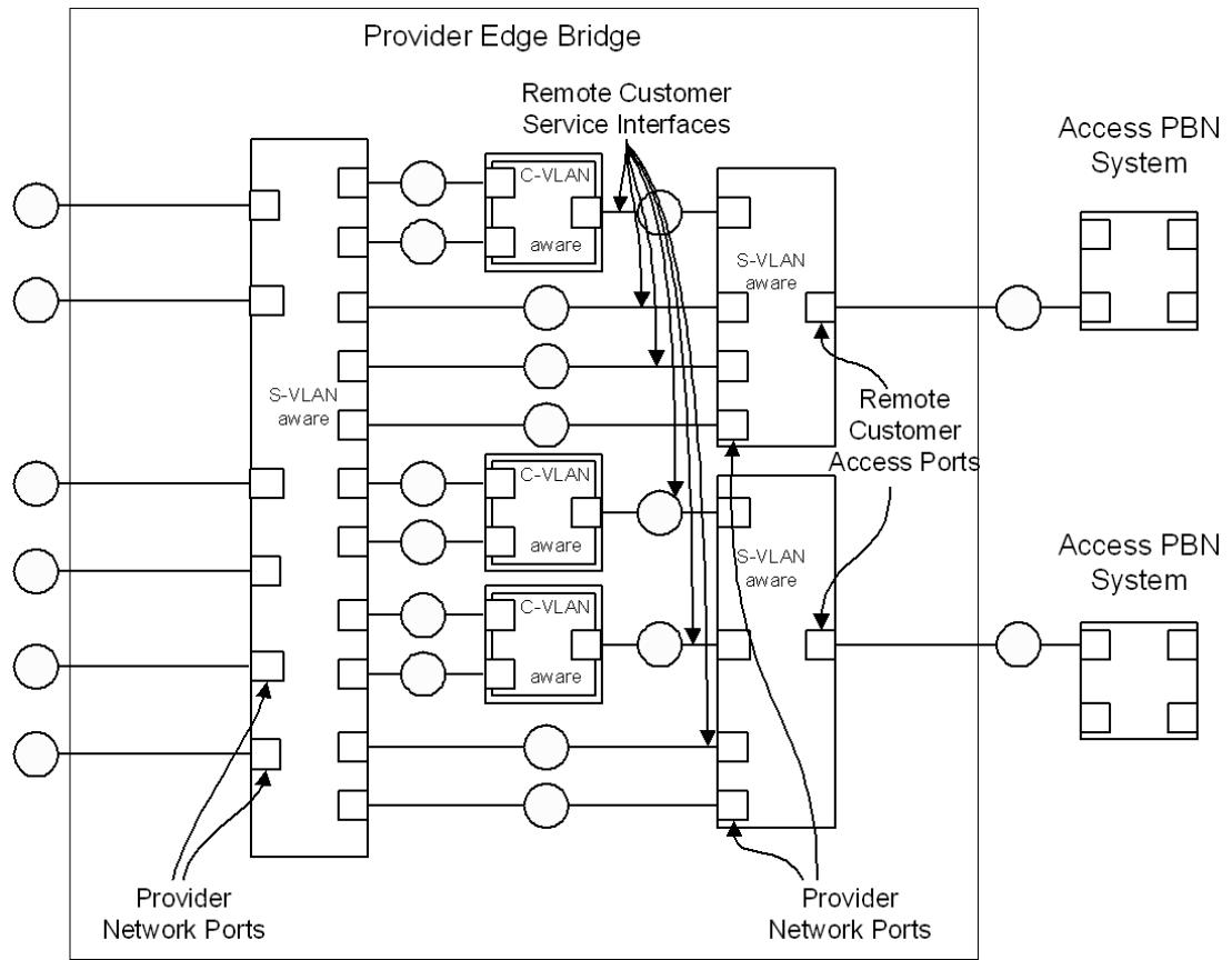
Figure 15-10—Remote Customer Access Ports (RCAPs)
Figure 15-11 shows a C-tagged RCSI. Since S-VLAN components are transparent to C-VLAN control PDUs, i.e., PDUs using addresses in Table 8-1 but not in Table 8-2, these control PDUs exchanged via the CEP reach the next (e.g., customer controlled) C-VLAN component across the access PBN. S-VLAN control PDUs, using addresses in Table 8-2, exchanged on the RCAP will normally reach the neighboring Provider Bridge in the adjacent PBN.
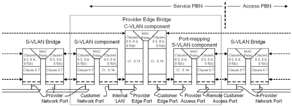
Figure 15-11—C-tagged RCSI to a PBN
Frames traversing the internal LAN between the Port-mapping S-VLAN component and the C-VLAN component do not contain an S-TAG. The S-VID for frames received on this interface by the Port-mapping S-VLAN component is provided by the PAP’s PVID.
Figure 15-12 shows a Port-based RCSI. In this case the PAP is connected to a CNP on the S-VLAN component. Frames carried over the internal LAN between the PAP and CNP do not contain an S-TAG. An S-VID is provided at each Port by the respective Port’s PVID. These S-VIDs are not required to have the same value.
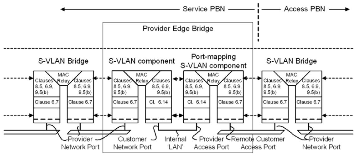
Figure 15-12—Port-based RCSI to a PBN
Figure 15-13 shows the PNP on the Port-mapping S-VLAN component connected to a PNP on the S-VLAN component. Service frames carried over this interface have S-TAGs and S-VID translation can be performed.
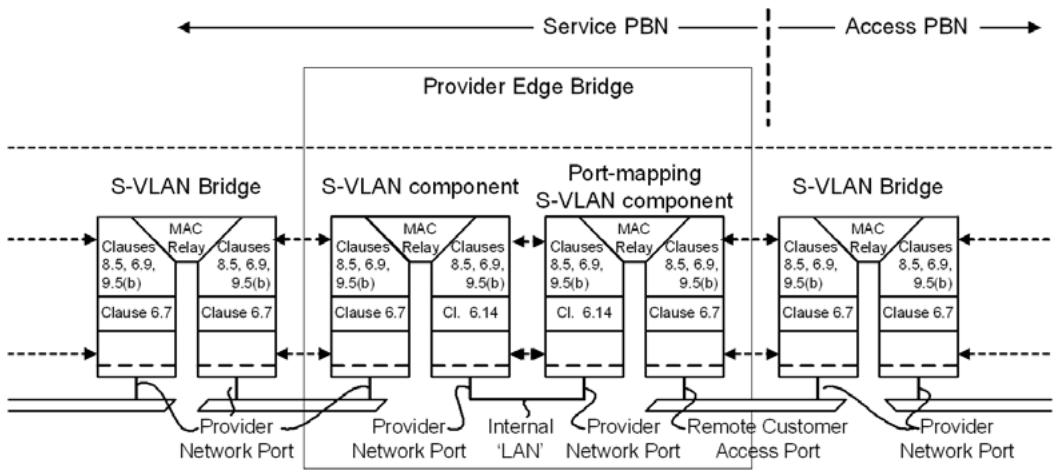
Figure 15-13—Provider Network Port (PNP) interface
15.7 Service instance segregation
Segregation of data frames associated with different MAC Service instances is achieved by supporting each service instance with a separate S-VLAN and ensuring that
a) Provider Bridges are configured such that no customer data frames are transmitted through a PNP untagged, i.e., without an S-TAG.
No frames are accepted, i.e., received and relayed, from any customer system without first being subject to service instance selection.
c) No frames are delivered to any customer system without explicit service instance identification.
d) Prior to transmission through a PNP, customer data frames are received through a CNP within the provider network that is exclusively accessed by a single customer. The S-VIDs of all frames received through that CNP correspond to service instances that the customer is permitted to access.
e) Provider Bridges and the S-VLAN component of each Provider Edge Bridge within the provider network can only be directly controlled by the service provider. Customer equipment, including customer-owned Provider Bridges, are not within the provider network and are controlled by the customer.
f) Only frames that have been transmitted through a PNP can be received through other PNPs within the provider network.
15.8 Service instance selection and identification
Service instance selection is provided for Port-based service interfaces by configuring a CNP with a PVID value corresponding to the S-VID used to identify the service instance and an Acceptable Frame Types value of Admit Only Untagged and Priority-tagged frames.
Service instance selection is provided for C-tagged service interfaces by a C-VLAN component internal to a Provider Edge Bridge. The C-VLAN component uses the C-VID to direct frames to an internal PEP supporting a specific service instance. Frames for at most one C-VLAN can be conveyed untagged over a single service instance. Management control of associating C-VIDs with PEPs is accomplished using the C-VID Registration Table (12.13.2), which provides equivalent functionality to configuring the PVID of the internal CNP with the S-VID of the service instance, and adding the PEP to the Member Set, and possibly Untagged Set, of the C-VLAN. No management control is provided for Protocol-based VID assignment on internal CNPs.
NOTE 1—A Provider Edge Bridge can configure the C-VLAN component associated with a CEP to select the same service instance for all frames. This creates a service interface similar, but not identical, to a Port-based service interface. The C-VLAN component allows modification of the C-TAG (insertion of a C-TAG with the PVID value in untagged frames, assigning the PVID value to priority-tagged frames, or stripping the C-TAG from frames forwarded through the PEP) but never forwards a frame with a null C-VID. A Port-based service interface does not modify the C-TAG of received frames in any way. A Provider Edge Bridge may offer a Port-based service interface by configuring the Port to be a CNP rather than a CEP; in which case, there is no associated C-VLAN component.
Service instance selection is provided by the attached customer system for S-tagged service interfaces. The CNP is configured with Enable Ingress Filtering (8.6.2), and the Port is only included in the Member Set for S-VLANs corresponding to service instances that the customer is permitted to use.
For all service interfaces described, the CNP determines the S-VID for each customer data frame as specified in 6.9.1 for an EISS instance using an S-TAG type.
The VID Translation Table for the Port (6.9.1) allows a service provider to assign S-VIDs independently from those used by a customer (or other service provider) to identify service instances on an S-tagged service interface (15.5). The table also allows customers to identify the same service instance by different VIDs at different interfaces.
NOTE 2—The means used by a service provider and a customer to determine the VIDs used by the customer to select and identify a given service instance are outside the scope of this standard.
The service instance for each frame received by the attached customer system is identified in the same way as frames transmitted using the same interface, but not necessarily in the same way that the service instance is selected or identified at other interfaces. A single service instance can support Port-based, C-tagged, and S-tagged service interfaces.
15.9 Service priority selection
For all service interface types, the service priority is selected using the received priority for each frame, possible regenerated using the Priority Regeneration Table (6.9.4). The mechanism for determining the received priority varies with the type of service interface.
Service priority selection is provided for Port-based service interfaces using the received priority signaled from the media access method of the port. If the media access method used to attach to the interface does not directly support priority, this will result in the selection of a single value for all frames. A customer system may also signal priority to a Port-based service interface on a per-frame basis by priority-tagging each frame with an S-TAG with a null VID. Subclause 6.13 specifies a function to support priority-tagging with an S-TAG on Customer Bridges.
Service priority selection is provided by C-tagged service interfaces using the priority conveyed in the C-TAG of each frame. A C-tagged service interface can provide a single service instance for all C-VIDs received and in this way function much as a Port-based service interface with the addition of the capability of the customer to independently signal priority with each frame.
Service priority selection is provided by S-tagged interfaces using the received priority decoded from the PCP field in the S-TAG.
15.10 Service access protection
A customer system or systems at a single location can attach to two or more service interfaces using separate LANs for attachment, thus providing fault tolerance through redundancy of the interface components.
16 Principles of Provider Bridged Network (PBN) operation
This clause establishes the principles and a model of PBN operation. It provides the context necessary to understand how the
a) Operation of individual Provider Bridges (Clause 8),
b) Configuration and management of individual Provider Bridges (Clause 12), and
c) Management of spanning tree and VLAN topologies within a provider network (Clause 7, Clause 11, Clause 13)
support, preserve, and maintain the quality of each instance of the MAC Service offered to the customers of the provider network (Clause 6, Clause 15), including
d) Independence of each service instance supported by a service provider from other service instances (Clause 15);
e) Identification of service instances within the provider network (Clause 15, 8.8);
f) Maintenance of service availability in the event of the failure, restoration, removal, or insertion of LAN components connecting a customer network to a provider network (Clause 6, Clause 11, Clause 13, 16.2).
A PBN is a Virtual Bridged Network that comprises Provider Bridges (S-VLAN Bridges and Provider Edge Bridges) and attached LANs, under the administrative control of a single service provider. The principal elements of provider network operation are those specified in Clause 7 for Virtual Bridged Networks in general, as amended by this clause.
NOTE 1—Unless explicitly stated, the term “provider network” in this standard refers to a PBN. The term “Provider Bridged Network (PBN)” is used exclusively to refer to networks configured and managed as specified by this clause and comprising only (a) Provider Bridges and Provider Edge Bridges and (b) communications media and equipment providing the ISS (IEEE Std 802.1AC). Although the requirements of Clause 15 are generally applicable to similar services, a generalized framework for all network designs that could support these requirements, while useful in the context of other equipment and services, is outside the scope of this standard. This clause describes specific best practice for PBNs to ensure that the requirements for Bridge functionality are clear. Conformance of a Provider Bridge implementation to this standard does not require that the implementation be used as specified in this clause, merely that it is capable of being so used.
NOTE 2—Within a provider network, an instance or instances of the MAC Service are reserved for the service provider’s own use to configure and manage the network. All frames associated with such service instances, and that are not confined to an individual LAN, are subject to service instance selection, segregation, and identification as specified in 16.1.
16.1 PBN overview
The principal elements of PBN operation comprise
a) Service instance segregation within the provider network for customer frames (15.6).
b) Service instance selection on ingress, and service instance identification on egress, for each customer frame (15.8).
c) Resource allocation and configuration to provide service instance connectivity (16.3).
and may also include
d) Management of customer end station address learning (16.4).
e) Prevention of connectivity loops formed through attached networks (16.5).
16.2 Provider Bridged Network (PBN)
An example PBN is illustrated by Figure 16-1.
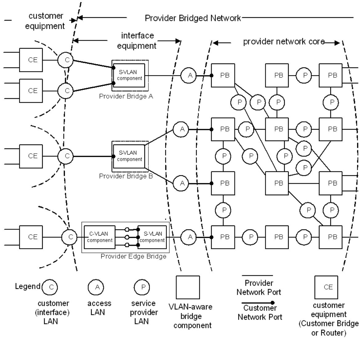
Figure 16-1—PBN with interface examples
Customer equipment attaches, via one or more customer interface LANs, to equipment that provides the service interfaces specified in Clause 15. That interface equipment can be located in the core of the provider network, such that both the equipment and the attached LANs are secure against direct addition of frames either by the customer or by others. More commonly the interface equipment connects to the network core using one or more access LANs, which can be subject to external interference. Figure 16-1 provides examples. Within the network core, Provider Bridges and LANs are secured so that only the service provider can manage the reception, transmission, and relay of frames between Provider Bridges.
The arbitrary physical network topology of the network core and the connectivity that it provides to support segregated instances (15.6) of the MAC Service is designed and managed (16.3) by the service provider to meet bandwidth and service availability requirements at the PNPs. Application of the S-VLAN ingress and egress rules at these Ports in support of service instance selection and identification (15.8) ensures that frames cannot be transmitted or received on any service instance by any customer’s equipment without prior agreement with the service provider.
Although the application of the ingress and egress rules, together with the use of the MSTP restrictedRole and restrictedTcn (13.27.64, 13.27.65) parameters and MVRP registration controls (16.3), permit service providers to allow direct attachment of customer-operated equipment to access LANs, there are commonly other reasons, such as Operations, Administration, and Maintenance (OAM) support of access LANs, why interface equipment is mandated. The interface equipment, as illustrated by, but not limited to, the examples in Figure 16-1 can be used to partition and enhance network access functionality to provide
a) Service instance multiplexing on a single access LAN;
b) Provision of resilient, and optionally physically route diverse, access;
c) Reduced management of customer use of multiple service instances;
d) Selective multiplexing of C-VLANs onto service instances;
e) Reliable identification of the customer point of attachment;
without requiring customer systems to understand the internal details of the provider network.
Provider Bridge A in Figure 16-1 uses physically separate customer interface LANs to provide separate Port-based service interfaces to the customer equipment and uses S-TAGs to multiplex the corresponding service instances over a single access LAN. The interface equipment can be managed by the service provider to use S-VIDs that do not require use of a VID Translation Table at the edge of the core network. Alternatively, the latter can translate S-VIDs to remove the need for such management, with all interface equipment using the same S-VIDs in the same way.
Provider Bridge B in Figure 16-1 uses a single customer interface LAN to provide a Port-based service interface to the customer equipment and uses two access LANs to provide resilient connectivity to distinct Provider Bridges in the core network. Receipt of Provider Bridge BPDUs by Bridge B protects against the failure of an access LAN, of one of the core Bridges, or of some internal physical connectivity within the provider network. Use of the MSTP restrictedRole and restrictedTcn parameters by PNPs ensures that receipt of frames from the access LANs cannot disrupt the active topology or address learning within the core network. Where multiple service instances are provided at a single customer point of attachment, both access links can be used.
Provider Edge Bridge C in Figure 16-1 provides a C-tagged service interface to the customer equipment and uses C-TAGs on the customer interface LAN to select between multiple S-VLAN-tagged service instances on the access LAN. Individual C-VLANs can be conveyed on any service instance, and this distribution of C-VLANs can be changed in response to changes in the connectivity offered by the service instances through customer systems at other points of customer attachment. The traffic for a particular C-VLAN can be the majority of that carried on a specific service instance; specifying that frames for that C-VLAN are untagged on the internal LAN that corresponds to that service instance within the Provider Edge Bridge allows those frames to be carried through the provider network without a C-VID following the S-VID if the overhead of conveying the additional octets is a concern.
NOTE 1—In the scenario where a customer network has multiple service interfaces to a provider network, and the customer network VLAN topology is such that frames sent from a single MAC source on different C-VLANs will enter the provider network on different service interfaces and be mapped to the same service instance (same S-VLAN), then the C-MAC address will appear to be duplicated and potentially cause oscillation in the learning process within the Provider Network. This scenario can be avoided by restricting a MAC address to enter the provider network at the same service interface for all C-VLANs, or by mapping the different C-VLANs to different service instances (different S-VLANs), or by restricting the service instance to be point-to-point so the provider Bridges do not need to learn the C-MAC addresses.
In some cases a service provider needs to reach a customer interface LAN that is not directly attached to the service provider’s network but is attached instead to another PBN. Figure 16-2 shows some examples in which a customer interface LAN is connected to an access PBN that is not the PBN providing service to the customer.
NOTE 2—The PBN providing access to the customer interface LANs in these examples can provide other services to its own customers as well.
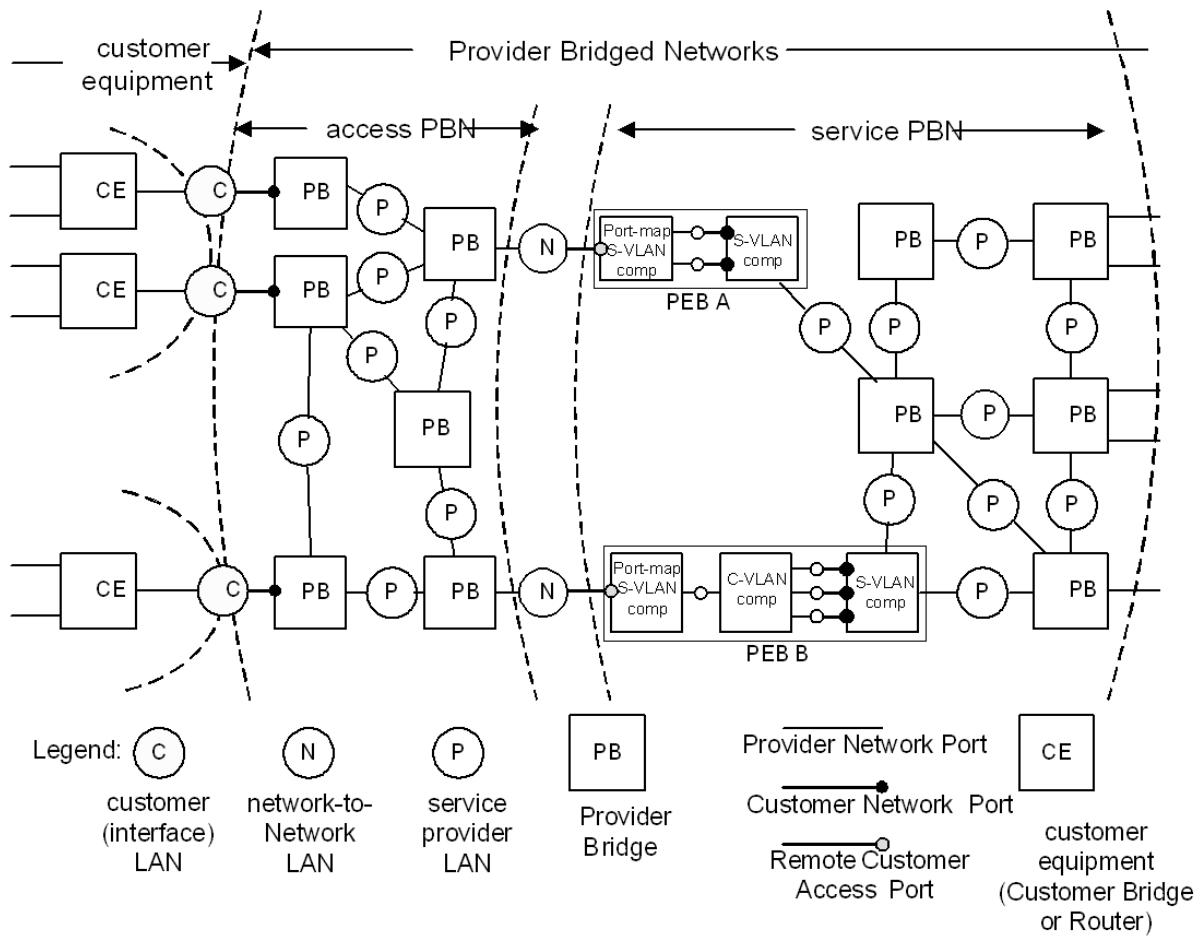
Figure 16-2—Examples of remote customer service access via a second PBN
In these examples the service provider uses a Port-based service provided by the access PBN to reach the customer interface LANs. Each such access service is identified by a distinct S-VID at the network-tonetwork interface LAN. The service PBN uses this S-VID to select an RCSI that provides either a Port-based or C-tagged service interface as specified in Clause 15. An RCSI provides service instance selection and identification (15.3) and service management for each customer interface LAN. Each RCSI carries frames to/from a single customer interface LAN.
PEB A in Figure 16-2 receives traffic from two customer interface LANs attached to the access PBN. The traffic from each customer interface LAN is carried over a separate RCSI. In the example shown each RCSI is connected to a Port-based service interface (CNP). If the two customer interface LANs participate in the same service instance (i.e., their RCSI CNPs belong to the same S-VLAN) a frame received from one RCSI CNP can be transmitted on the other RCSI CNP. Thus a frame received on the network-to-network LAN with one S-VID can be subsequently transmitted on that same external LAN with a different S-VID. This behavior is sometimes called “Hairpin Switching”.20
The structure allowing a frame to be received and subsequently transmitted on the same external interface while avoiding loops and misdelivery of multicast frames is illustrated in Figure 16-3. Frames from/to $\mathrm { C E } _ { 1 }$ have S-VID A and frames from/to $\mathrm { C E } _ { 2 }$ have S-VID B. Thus the two customer interface LANs cannot exchange traffic within the access PBN. In PEB A external S-VIDs A and B select or identify different RCSI PAPs.
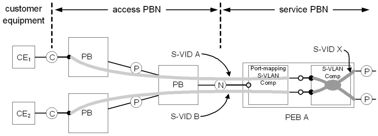
Figure 16-3—Access service separation and “Hairpin Switching”
In this example, both RCSI CNPs belong to the same internal S-VLAN in the service provider’s network identified by S-VID X. Frames can be relayed between all Ports belonging to S-VID X, including between the two RCSIs. When a frame is received on one RCSI and subsequently transmitted on the other RCSI the frame is received and transmitted on the same external RCAP. However, in this case the external S-VIDs in the received and transmitted frames are different. If the sets of endpoints in the access PBN associated with each external S-VID are disjoint there is no possibility of looping or misdelivery of multicast frames.
PEB B in Figure 16-2 receives traffic from a customer interface LAN and provides a C-tagged RCSI (CEP). The capabilities of a C-tagged RCSI are the same as those provided by an external CEP as described above.
16.3 Service instance connectivity
The VLAN Topology of each S-VLAN is established by the mechanisms introduced in 7.1 and Figure 7-1. The service provider can use and configure MSTP to provide a number of independent spanning tree active topologies and can assign each S-VLAN independently to one of these to best use the resources in the network. MVRP running in the context of each spanning tree active topology configures the extent of each S-VLAN to the subset of that active topology necessary to support connectivity between the customer points of attachment to the MAC Service instance provided, and it can reconfigure that connectivity as required if the spanning tree active topology changes.
NOTE 1—Autoconfiguration of the extent of each S-VLAN is accomplished by the service provider configuring the MVRP Administrative Control “Registration Fixed (New ignored)” for the S-VLAN on each CNP where the corresponding MAC Service Instance can be selected. The Enable Ingress Filtering parameter is not typically used within an individual provider network, as it limits the ability of the network to carry service instances following changes in the active topology. However, it can be used to limit the reachability of service instances used by the service provider for network management and to restrict service instances carried from one provider network domain to another.
The operation of MSTP within a provider network is independent of the operation of any spanning tree protocol within attached customer networks. This independence is achieved by using the Provider Bridge Group Address (Table 8-1) as the destination address of all MSTP BPDUs transmitted on all Provider Bridge Ports and by setting the restrictedRole and restrictedTcn parameters (13.27.64, 13.27.65) for CNPs.
Frames received by CNPs and addressed to the Bridge Group Address are subject to service instance selection and relay in the same way as customer data frames.
NOTE 2—Customer BPDUs addressed to the Bridge Group Address are conveyed transparently, allowing the customer to use an instance of MSTP or RSTP that is completely independent of the provider network to establish and maintain full and loop-free connectivity of the customer connected networks and services. A customer can also use MVRP to limit the transmission of frames assigned to C-VLANs to the service instances required for C-VLAN connectivity.
The operation of MVRP within a provider network is independent of the operation of any configuration protocol within attached customer networks. The Provider Bridge MVRP Address (Table 8-1) is used as the destination address of all MVRPDUs transmitted in support of the MVRP Application. Frames received by CNPs and addressed to an MRP Application Address (Table 10-1) not in use by the S-VLAN component are subject to service instance selection and relay in the same way as customer data frames. The MVRP Administrative Control for each S-VLAN is either “Registration Fixed (New ignored)” or “Registration Forbidden” on all CNPs, so no information is received from any Provider Bridge MVRPDU that has been erroneously transmitted by a customer system.
16.4 Service provider learning of customer end station addresses
Customer data frames for any given MAC Service instance are restricted to that part of the provider network that supports the VLAN topology of the associated S-VLAN as described in 16.3 and are further restricted by learning the source addresses of frames as described in Clause 7 and Clause 8.
In a PBN that commonly provides interfaces to each customer at a small fraction of the total number of customer interfaces provided, the requirement for learning customer end station addresses can be much reduced by applying enhanced filtering utility criteria (8.7). In particular, learning can be restricted to the ingress and egress Provider Bridge Ports of each S-VLAN that connects only two customer points of attachment, or to the customer systems attached to those Ports.
The "new" flag in MVRP can be used to flush learned addresses on a specific service instance in a PBN in response to a topology change in the Customer Network.
16.5 Detection of connectivity loops through attached networks
The transmission and reception of MSTP BPDUs through CNPs will detect accidental direct connection of those ports, or their interconnection by a network that is transparent to frames with the Provider Bridge Group Address as the destination MAC address. However, a service provider cannot rely on any customer network relaying such frames and should develop a policy and mechanisms to deal with potential data loops that can arise if the attached customer systems do not correctly operate their own instance or instances of a spanning tree protocol.
NOTE 1—Use of the restrictedRole parameter at ingress ports ensures that receipt of BPDUs addressed to the Provider Bridge Group Address cannot disrupt internal connectivity within the provider network.
NOTE 2—Specification of service provider policies, mechanisms, and heuristics used to detect or minimize the impact of data loops created by customer systems is not addressed by this standard. They can include, but are not limited to, bandwidth limitation, charging policies, detection of the repetitive movement of the apparent location of customer stations, and customer agreement to allow the use of service provider loop detection protocols by not filtering the associated frames.
NOTE 3—A data loop is not the only possible cause of excess bandwidth consumption by a given customer of a provider network, and the service provider is usually required to meet service guarantees to other customers irrespective of the cause of the excess bandwidth demand. Data loops are not a unique threat to satisfactory overall network performance. Their distinct characteristic is consumption of discretionary bandwidth without benefiting any customer. The customer that creates the loop can suffer particularly serious network degradation or excess cost as the service provider limits the total bandwidth consumed by that customer. It is therefore in the interests of each customer and the service provider to raise service satisfaction by preventing and detecting loops.
Each C-VLAN component within a Provider Edge Bridge implements RSTP, with the enhancements to support loop-free connectivity between CEPs, as specified in 13.41, thus interoperating with customer equipment and spanning tree configurations to support reliable and deterministic prevention of loops, and supporting provision of redundant connectivity.
16.6 Network management
Management of a Provider Bridge is directly under the control of the service provider. Provider network customers shall not have access to managed objects related to elements of Provider Bridges within the provider network.
17 Management Information Base (MIB)
The clause contains a complete SMIv2 MIB set for all features of this standard. Previous versions of this standard (e.g., IEEE Std 802.1Q-2005, IEEE Std 802.1Q-1998) relied on MIB modules defined by the IETF Bridge Working Group. IETF RFC 4663 [B32] describes more details of the IETF transition of responsibility for bridging-related MIB modules from the IETF Bridge MIB Working Group to the IEEE 802.1 Working Group.
17.1 Internet Standard Management Framework
For a detailed overview of the documents that describe the current Internet Standard Management Framework, refer to section 7 of IETF RFC 3410 (2002).
Managed objects are accessed via a virtual information store, termed the Management Information Base or MIB. MIB objects are generally accessed through the Simple Network Management Protocol (SNMP). Objects in the MIB are defined using the mechanisms defined in the Structure of Management Information (SMI). This clause specifies a MIB module that is compliant to the SMIv2, which is described in IETF STD 58, IETF RFC 2578, IETF RFC 2579, and IETF RFC 2580.
Control of the transmission of Fault Alarms, which are Notifications in SNMP, are described by IETF STD 62, IETF RFC 3413, IETF RFC 3417, and IETF RFC 4789. As a consequence of the concentration of control of the reporting of SNMP Notifications in the SNMP-TARGET-MIB and SNMP-NOTIFICATION-MIB of IETF RFC 3413, the variables controlling Fault Alarm notifications described in Clause 12 [item e) in 12.14.5.1.3, item f) in 12.14.6.1.3, and item j) in 12.14.7.1.3] require no specific objects in the MIB modules in 17.7.
17.2 Structure of the MIB
The IEEE 802.1Q MIB is divided into a number of modules corresponding to the project that created the functionality. The managed objects in most of these modules have been reindexed to allow their use within the PBB MIB module (and thus avoid a duplication of objects).
A summary of the modules contained in this clause is presented in Table 17-1.
Table 17-1—Structure of the MIB modules
<table><tr><td>Module</td><td>Subclause</td><td>Defining IEEE standard</td><td>Reference</td><td>Notes</td></tr><tr><td>IEEE8021-TC-MIB</td><td>17.7.1</td><td>802.1ap</td><td>—</td><td>Textual conventions for all modules</td></tr><tr><td>IEEE8021-BRIDGE-MIB</td><td>17.7.2</td><td>802.1D, 802.1p, and 802.1t</td><td>Clause 8</td><td>Adapted from IETF RFC 4188 and IETF RFC 4363</td></tr><tr><td>IEEE8021-SPANNING-TREE-MIB</td><td>17.7.3</td><td>802.1w</td><td>Clause 13</td><td>Adapted from IETF RFC 4318</td></tr><tr><td>IEEE8021-Q-BRIDGE-MIB</td><td>17.7.4</td><td>802.1Q, 802.1u, and 802.1v</td><td>Clause 8</td><td>Adapted from IETF RFC 4363</td></tr><tr><td>IEEE8021-PB-MIB</td><td>17.7.5</td><td>802.1ad</td><td>Clause 16</td><td>Initial version in IEEE Std 802.1ap</td></tr><tr><td>IEEE8021-MSTP-MIB</td><td>17.7.6</td><td>802.1s</td><td>Clause 13</td><td>Initial version in IEEE Std 802.1ap</td></tr><tr><td>IEEE8021-CFM-MIB</td><td>17.7.7.1</td><td>802.1ag</td><td>Clause 20</td><td>Initial version in IEEE Std 802.1ag</td></tr><tr><td>IEEE8021-CFM-V2-MIB</td><td>17.7.7.2</td><td>802.1ag</td><td>Clause 20</td><td>Initial version in IEEE Std 802.1ap</td></tr><tr><td>IEEE8021-PBB-MIB</td><td>17.7.8</td><td>802.1ah</td><td>Clause 26</td><td>Initial version in IEEE Std 802.1ap</td></tr><tr><td>IEEE8021-DDCFM-MIB</td><td>17.7.9</td><td>802.1Qaw</td><td>Clause 29</td><td>Initial version of IEEE Std 802.1Qaw</td></tr><tr><td>IEEE8021-PBBTE-MIB</td><td>17.7.10</td><td>802.1Qay</td><td>—</td><td>Initial version in IEEE Std 802.1Qay</td></tr><tr><td>IEEE8021-TPMR-MIB</td><td>17.7.11</td><td>802.1aj</td><td>5.13, 5.15</td><td>Initial version in IEEE Std 802.1aj</td></tr><tr><td>IEEE8021-FQTSS-MIB</td><td>17.7.12</td><td>802.1Qav</td><td>Clause 34</td><td>Initial version in IEEE Std 802.1Qav</td></tr><tr><td>IEEE8021-CN-MIB</td><td>17.7.13</td><td>802.1Qau</td><td>Clause 30</td><td>Initial version in IEEE Std 802.1Qau</td></tr><tr><td>IEEE8021-SRP-MIB</td><td>17.7.14</td><td>802.1Qat</td><td>Clause 35</td><td>Initial version in IEEE Std 802.1Qat</td></tr><tr><td>IEEE8021-MVRPX-MIB</td><td>17.7.15</td><td>802.1Qbe</td><td>11.2</td><td>Initial version in IEEE Std 802.1Qbe</td></tr><tr><td>IEEE8021-MIRP-MIB</td><td>17.7.16</td><td>802.1Qbe</td><td>Clause 39</td><td>Initial version in IEEE Std 802.1Qbe</td></tr><tr><td>IEEE8021-PFC-MIB</td><td>17.7.17</td><td>802.1Qbb</td><td>Clause 36</td><td>Initial version in IEEE Std 802.1Qbb</td></tr><tr><td>IEEE8021-TEIPS-MIB</td><td>17.7.18</td><td>802.1Qbf</td><td>26.11</td><td>Initial version in IEEE Std 802.1Qbf</td></tr><tr><td>IEEE8021-SPB-MIB</td><td>17.7.19</td><td>802.1aq</td><td>Clause 27, Clause 28</td><td>Initial version in IEEE Std 802.1aq</td></tr><tr><td>IEEE8021-EVB-MIB</td><td>17.7.20</td><td>802.1Qbg</td><td>5.23, 5.24</td><td>Initial version in IEEE Std 802.1Qbg</td></tr><tr><td>IEEE8021-ECMP-MIB</td><td>17.7.21</td><td>802.1Qbp</td><td>Clause 44, Clause 28</td><td>Initial version in IEEE Std 802.1Qbp</td></tr></table>
17.2.1 Structure of the IEEE8021-TC-MIB
The purpose of the IEEE8021-TC-MIB is to define textual conventions used throughout the IEEE 802.1Q MIB modules. Textual conventions (TCs) originally appeared in each of the MIB modules for IEEE Std 802.lQ produced by the IETF. However, with the transition of all modules for IEEE Std 802.1Q to this clause, it made sense to have a single module with all the textual conventions contained within it. Note that many of the original IETF TCs are still used in the various MIB modules for VLAN-Bridge management and they have not been imported here.
NOTE—The IEEE8021-FQTSS-MIB module in 17.7.12 defines additional TEXTUAL-CONVENTIONs that are utilized by the managed objects that support use of the Credit-based shaper algorithm (8.6.8.2, 34).
The textual conventions contained in this IEEE8021-TC module are summarized in Table 17-2.
Table 17-2 — IEEE8021-TC-MIB Structure
<table><tr><td>IEEE MIB object</td><td>Reference</td></tr><tr><td>IEEE8021PbbComponentIdentifier</td><td>12.3 l)</td></tr><tr><td>IEEE8021PbbComponentIdentifierOrZero</td><td>12.3 l)</td></tr><tr><td>IEEE8021PbbServiceIdentifier</td><td>12.16.3, 12.16.5</td></tr><tr><td>IEEE8021PbbServiceIdentifierOrUnassigned</td><td>12.16.3, 12.16.5</td></tr><tr><td>IEEE8021PbbIngressEgress</td><td>12.16.3, 12.16.5</td></tr><tr><td>IEEE8021PriorityCodePoint</td><td>12.6.2</td></tr><tr><td>IEEE8021BridgePortNumber</td><td>12.3 i), 17.3.2.2</td></tr><tr><td>IEEE8021BridgePortNumberOrZero</td><td>12.3 i), 17.3.2.2</td></tr><tr><td>IEEE8021BridgePortType</td><td>12.16.1.1.3 h4), 12.16.2.1, 12.13.1.1, 12.13.1.2</td></tr><tr><td>IEEE8021VlanIndex</td><td>9.6</td></tr><tr><td>IEEE8021VlanIndexOrWildcard</td><td>9.6</td></tr><tr><td>IEEE8021MstIdentifier</td><td>13.8</td></tr><tr><td>IEEE8021ServiceSelectorType</td><td>—</td></tr><tr><td>IEEE8021ServiceSelectorValueOrNone</td><td>—</td></tr><tr><td>IEEE8021ServiceSelectorValue</td><td>—</td></tr><tr><td>IEEE8021PortAcceptableFrameTypes</td><td>12.10.1.3, 12.13.2.3, 12.13.2.4</td></tr><tr><td>IEEE8021PriorityValue</td><td>12.13.2.3</td></tr><tr><td>IEEE8021PbbTeProtectionGroupId</td><td>12.19.2</td></tr><tr><td>IEEE8021PbbTeEsp</td><td>3.75</td></tr><tr><td>IEEE8021PbbTeTSidId</td><td>3.243</td></tr><tr><td>IEEE8021PbbTeProtectionGroupConfigAdmin</td><td>26.10.3.3.4, 26.10.3.3.5, 26.10.3.3.6, 26.10.3.3.7, 12.18.2.1.3 d)</td></tr><tr><td>IEEE8021PbbTeProtectionGroupActiveRequests</td><td>12.18.2.3.2</td></tr><tr><td>ieee8021TeipsV2Ipgid</td><td>12.24.2</td></tr><tr><td>ieee8021TeipsV2IpgConfigAdmin</td><td>26.10.3.3.4, 26.10.3.3.5, 26.10.3.3.6, 26.10.3.3.7, 12.14.2.1.2 f) and j)</td></tr><tr><td>ieee8021TeipsV2IpgActiveRequests</td><td>12.24.2.2.1 b)</td></tr><tr><td>ieee8021TeipsV2Segid</td><td>26.11.1, 3.98</td></tr><tr><td>ieee8021TeipsV2Smpid</td><td>26.11.1, 3.192</td></tr></table>
The textual conventions used by IEEE 802.1Q MIB modules not contained in this TC module, but contained in IETF RFC 4318 and IETF RFC 4363 are as follows:
BridgeId
Timeout
PortList
VlanIdOrAny
VlanIdOrNone
VlanIdOrAnyOrNone
17.2.2 Structure of the IEEE8021-BRIDGE-MIB
The work in this standard is based upon the BRIDGE MIB version in IETF RFC 4188 and the P-BRIDGE MIB originally in IETF RFC 4363. While many tables and objects are similar, this IEEE8021-BRIDGE-MIB has been reindexed and rerooted with its inclusion in this clause.
Objects in this MIB module are arranged into subtrees. Each subtree is organized as a set of related objects. The overall structure and assignment of objects to their subtrees is shown below. Where appropriate, the corresponding IETF RFC 4188 object name, IEEE Std 802.1D-2004 [B10] management object name, and reference is also included. If the IETF RFC mapping is missing, it means there is no equivalent in the old MIBs. If the Managed Object is missing, it means that no managed object is specified in the referenced clause.
Table 17-3 indicates the structure of the IEEE8021-BRIDGE-MIB module as well as showing its relationship to the IETF MIB that is being obsoleted.
Table 17-3—IEEE8021-BRIDGE-MIB structure and relationship to IETF RFC 4188 and this standard
<table><tr><td>IEEE MIB table/object</td><td>IETF MIB table/object</td><td>Reference</td></tr><tr><td>ieee8021BridgeBaseTable</td><td>dot1dBase</td><td>12.4.1</td></tr><tr><td>ieee8021BridgeBaseComponentId*</td><td>—</td><td>—</td></tr><tr><td>ieee8021BridgeBaseBridgeAddress</td><td>dot1dBaseBridgeAddress</td><td>12.4.1.1.3 a)</td></tr><tr><td>ieee8021BridgeBaseNumPorts</td><td>dot1dBaseNumPorts</td><td>12.4.1.1.3 c)</td></tr><tr><td>ieee8021BridgeBaseComponentType</td><td>—</td><td>12.3 m)</td></tr><tr><td>ieee8021BridgeBaseDeviceCapabilities</td><td>dot1dDeviceCapabilities</td><td>12.10.1.1.3 b)</td></tr><tr><td>ieee8021BridgeBaseTrafficClassesEnabled</td><td>dot1dTrafficClassesEnabled</td><td>—</td></tr><tr><td>ieee8021BridgeBaseMmrpEnabledStatus</td><td>dot1dGmrpStatus</td><td>—</td></tr><tr><td>ieee8021BridgeBaseRowStatus</td><td></td><td></td></tr><tr><td>ieee8021BridgeBasePortTable</td><td>dot1dBasePortTable</td><td>12.4.2</td></tr><tr><td>ieee8021BridgeBasePortComponentId*</td><td>—</td><td>—</td></tr><tr><td>ieee8021BridgeBasePort*</td><td>dot1dBasePort</td><td>12.4.2.1</td></tr><tr><td>ieee8021BridgeBasePortIfIndex</td><td>dot1dBasePortIfIndex</td><td>—</td></tr><tr><td>ieee8021BridgeBasePortDelayExceededDiscards</td><td>dot1dBasePortDelayExceededDiscards</td><td>12.6.1.1.3 f)</td></tr><tr><td>ieee8021BridgeBasePortMtuExceededDiscards</td><td>dot1dBasePortMtuExceededDiscards</td><td>12.6.1.1.3 g)</td></tr><tr><td>ieee8021BridgePortCapabilities</td><td>dot1dPortCapabilities</td><td>12.10.1.1.3 c)</td></tr><tr><td>ieee8021BridgeBasePortTypeCapabilities</td><td></td><td>—</td></tr><tr><td>ieee8021BridgeBasePortType</td><td></td><td>—</td></tr><tr><td>ieee8021BridgeBasePortExternal</td><td></td><td>—</td></tr><tr><td>ieee8021BridgeBasePortAdminPointToPoint</td><td>dot1dStpPortAdminPointToPoint</td><td>12.8.2.1.3 o)</td></tr><tr><td>ieee8021BridgeBasePortOperPointToPoint</td><td>dot1dStpPortOperPointToPoint</td><td>12.8.2.1.3 p)</td></tr><tr><td>ieee8021BridgeBasePortName</td><td>ifDescr</td><td>12.4.2.1</td></tr><tr><td>ieee8021BridgeTpPortTable</td><td>dot1dTpPortTable</td><td>12.4.2</td></tr><tr><td>ieee8021BridgeTpPortComponentId*</td><td>—</td><td>—</td></tr><tr><td>ieee8021BridgeTpPort*</td><td>dot1dTpPort</td><td>—</td></tr><tr><td>ieee8021BridgeTpPortMaxInfo</td><td>dot1dTpPortMaxInfo</td><td>—</td></tr><tr><td>ieee8021BridgeTpPortInFrames</td><td>dot1dTpPortInFrames</td><td>12.6.1.1.3 a)</td></tr><tr><td>ieee8021BridgeTpPortOutFrames</td><td>dot1dTpPortOutFrames</td><td>12.6.1.1.3 d)</td></tr><tr><td>ieee8021BridgeTpPortInDiscards</td><td>dot1dTpPortInDiscards</td><td>12.6.1.1.3 c)</td></tr><tr><td>ieee8021BridgePortPriorityTable</td><td>dot1dPortPriorityTable</td><td>12.6.2</td></tr><tr><td>(AUGMENTS ieee8021BridgeBasePortEntry)</td><td>(AUGMENTS dot1dBasePortEntry)</td><td>—</td></tr><tr><td>ieee8021BridgePortDefaultUserPriority</td><td>dot1dPortDefaultUserPriority</td><td>—</td></tr><tr><td>ieee8021BridgePortNumTrafficClasses</td><td>dot1dPortNumTrafficClasses</td><td>—</td></tr><tr><td>ieee8021BridgePortPriorityCodePointSelection</td><td></td><td>12.6.2.6, 12.6.2.7</td></tr><tr><td>ieee8021BridgePortUseDEI</td><td></td><td>12.6.2.11, 12.6.2.12</td></tr><tr><td>ieee8021BridgePortRequireDropEncoding</td><td></td><td>12.6.2.13, 12.6.2.14</td></tr><tr><td>ieee8021BridgePortServiceAccessPrioritySelection</td><td></td><td>12.6.2.15, 12.6.2.16</td></tr><tr><td>ieee8021BridgeUserPriorityRegenTable</td><td>dot1dUserPriorityRegenTable</td><td>IEEE Std 802.1AC</td></tr><tr><td>ieee8021BridgeUserPriorityRegenComponentId*</td><td></td><td>—</td></tr><tr><td>ieee8021BridgeBasePort*</td><td>dot1dBasePort</td><td>—</td></tr><tr><td>ieee8021BridgeUserPriority*</td><td>dot1dUserPriority</td><td>—</td></tr><tr><td>ieee8021BridgeRegenUserPriority</td><td>dot1dRegenUserPriority</td><td>—</td></tr><tr><td>ieee8021BridgeTrafficClassTable</td><td>dot1dTrafficClassTable</td><td>Table 8-4</td></tr><tr><td>ieee8021BridgeTrafficClassComponentId*</td><td></td><td>—</td></tr><tr><td>ieee8021BridgeBasePort*</td><td>dot1dBasePort</td><td>—</td></tr><tr><td>ieee8021BridgeTrafficClassPriority*</td><td>dot1dTrafficClassPriority</td><td>—</td></tr><tr><td>ieee8021BridgeTrafficClass</td><td>dot1dTrafficClass</td><td>—</td></tr><tr><td>ieee8021BridgePortOutboundAccessPriorityTable</td><td>dot1dPortOutboundAccessPriority-Table</td><td>Table 8-4</td></tr><tr><td>ieee8021BridgePortOutboundAccessPriorityComponentId*</td><td></td><td>—</td></tr><tr><td>ieee8021BridgeBasePort*</td><td>dot1dBasePort</td><td>—</td></tr><tr><td>ieee8021BridgePortOutboundAccessPriority*</td><td>dot1dPortOutboundAccessPriority</td><td>—</td></tr><tr><td>ieee8021BridgePortDecodingTable</td><td></td><td>12.6.2</td></tr><tr><td>ieee8021BridgePortDecodingComponentId*</td><td></td><td>—</td></tr><tr><td>ieee8021BridgePortDecodingPortNum*</td><td></td><td>—</td></tr><tr><td>ieee8021BridgePortDecodingPriorityCodePointRow*</td><td></td><td>—</td></tr><tr><td>ieee8021BridgePortDecodingPriorityCodePoint*</td><td></td><td>—</td></tr><tr><td>ieee8021BridgePortDecodingPriority</td><td></td><td>12.6.2.7, 12.6.2.8</td></tr><tr><td>ieee8021BridgePortDecodingDropEligible</td><td></td><td>12.6.2.11, 12.6.2.12</td></tr><tr><td>ieee8021BridgePortEncodingTable</td><td></td><td>12.6.2</td></tr><tr><td>ieee8021BridgePortEncodingComponentId*</td><td></td><td>—</td></tr><tr><td>ieee8021BridgePortEncodingPortNum*</td><td></td><td>—</td></tr><tr><td>ieee8021BridgePortEncodingPriorityCodePointRow*</td><td></td><td>—</td></tr><tr><td>ieee8021BridgePortEncodingPriorityCodePoint*</td><td></td><td>—</td></tr><tr><td>ieee8021BridgePortEncodingDropEligible*</td><td></td><td>—</td></tr><tr><td>ieee8021BridgePortEncodingPriority</td><td></td><td>12.6.2.9, 12.6.2.10</td></tr><tr><td>ieee8021BridgeServiceAccessPriorityTable</td><td></td><td>—</td></tr><tr><td>ieee8021BridgeServiceAccessPriorityComponentId*</td><td></td><td>—</td></tr><tr><td>ieee8021BridgeServiceAccessPriorityPortNum*</td><td></td><td>—</td></tr><tr><td>ieee8021BridgeServiceAccessPriorityReceived*</td><td></td><td>—</td></tr><tr><td>ieee8021BridgeServiceAccessPriorityValue</td><td></td><td>12.6.2.15, 12.6.2.16</td></tr><tr><td>ieee8021BridgePortMrpTable</td><td>dot1dPortGarpTable</td><td>12.9</td></tr><tr><td>(AUGMENTS ieee8021BridgeBasePortEntry)</td><td>(AUGMENTS dot1dBasePortEntry)</td><td>12.9.1.1, 12.9.1.2</td></tr><tr><td>ieee8021BridgePortMrpJoinTime</td><td>dot1dPortGarpJoinTime</td><td>—</td></tr><tr><td>ieee8021BridgePortMrpLeaveTime</td><td>dot1dPortGarpLeaveTime</td><td>—</td></tr><tr><td>ieee8021BridgePortMrpLeaveAllTime</td><td>dot1dPortGarpLeaveAllTime</td><td>—</td></tr><tr><td>ieee8021BridgePortMmrpTable</td><td>dot1dPortGmrpTable</td><td>12.11</td></tr><tr><td>(AUGMENTS ieee8021BridgeBasePortEntry)</td><td>(AUGMENTS dot1dBasePortEntry)</td><td>—</td></tr><tr><td>ieee8021BridgePortMmrpEnabledStatus</td><td>dot1dPortGmrpStatus</td><td>—</td></tr><tr><td>ieee8021BridgePortMmrpFailedRegistrations</td><td>dot1dPortGmrpFailedRegistrations</td><td>—</td></tr><tr><td>ieee8021BridgePortMmrpLastPduOrigin</td><td>dot1dPortGmrpLastPduOrigin</td><td>—</td></tr><tr><td>ieee8021BridgePortRestrictedGroupRegistration</td><td>dot1dPortRestrictedGroupRegistration</td><td>12.11.1.3</td></tr><tr><td>ieee8021BridgeILanIfTable</td><td></td><td>17.3.2.2</td></tr><tr><td>ieee8021BridgeILanIfRowStatus</td><td></td><td>—</td></tr><tr><td>ieee8021BridgeDot1dPortTable</td><td></td><td>17.5.3</td></tr><tr><td>ieee8021BridgeBasePortComponentId*</td><td></td><td>—</td></tr><tr><td>ieee8021BridgeBasePort*</td><td></td><td>—</td></tr><tr><td>ieee8021BridgeDot1dPortRowStatus</td><td></td><td>—</td></tr><tr><td colspan="2">ieee8021BridgePortTable</td><td>12.5.1</td></tr><tr><td></td><td>ieee8021BridgePhyPort</td><td></td></tr><tr><td></td><td>ieee8021BridgePhyIfIndex</td><td></td></tr><tr><td></td><td>8021BridgePhyMacAddress</td><td></td></tr><tr><td></td><td>ieee8021BridgePhyPortToComponentId</td><td></td></tr><tr><td></td><td>ieee8021BridgePhyPortToInternalPort</td><td></td></tr><tr><td colspan="2">ieee8021BridgeBaseIfToPortTable</td><td>17.3.2</td></tr><tr><td></td><td>ieee8021BridgeBaseIfToPortComponentID</td><td></td></tr><tr><td></td><td>ieee8021BridgeBaseIfIndexPort</td><td></td></tr></table>
*This object is an INDEX of the table in which it resides.
The IEEE8021-BRIDGE-MIB contains the following object subtrees:
a) The ieee8021BridgeBase Subtree
This subtree contains the objects that are applicable to all types of Bridges.
b) The ieee8021BridgeTp Subtree
This subtree contains objects that describe the entity’s state with respect to transparent bridging. If transparent bridging is not supported, this subtree will not be implemented. This subtree is applicable to transparent-only Bridges.
c) The ieee8021BridgePriority Subtree
This subtree contains the objects for configuring and reporting status of Priority-based queuing mechanisms in a Bridge. This includes per Bridge Port user_priority treatment, mapping of user_priority in frames into internal traffic classes, and outbound user_priority and access_priority.
d) The ieee8021BridgeMrp Subtree
This subtree contains the objects for configuring and reporting on operation of the Multiple Registration Protocol (MRP).
e) The ieee8021BridgeMmrp Subtree
This subtree contains the objects for configuring and reporting on operation of the Multiple MAC Registration Protocol (MMRP).
f) The ieee8021BridgeInternal LAN Subtree
This subtree contains the objects for configuring and reporting on operation of the Internal LAN interface. An I-LAN Interface is used to create internal connections between Bridge Ports in an IEEE 802.1 device.
The IEEE Std 802.1D-2004 [B10] management objects in Table 17-4 have not been included in the BRIDGE-MIB module for the indicated reasons. Note that there is a conformance requirement that the base modules SNMPv2-MIB [RFC3418] and IF-MIB [RFC2863] will be implemented as a default on all Bridges.
Table 17-4 — IEEE 802.1D objects not in the IEEE8021-BRIDGE-MIB
<table><tr><td>IEEE 802.1D object</td><td>Disposition</td></tr><tr><td>Bridge.BridgeName</td><td>Same as sysDescr (SNMPv2-MIB)</td></tr><tr><td>Bridge.BridgeUpTime</td><td>Same as sysUpTime (SNMPv2-MIB)</td></tr><tr><td>Bridge.PortAddresses</td><td>Same as ifPhysAddress (IF-MIB)</td></tr></table>
17.2.3 Structure of the IEEE8021-SPANNING-TREE MIB
A RSTP MIB originally appeared in IETF RFC 4318. While many tables and objects are similar, the IEEE8021-SPANNING-TREE MIB has been merged with spanning tree objects from the original BRIDGE MIB in IETF RFC 4188 and also reindexed and rerooted with its inclusion in this subclause.
This subclause defines an SMIv2 MIB module for managing RSTP capability originally defined by the IEEE Std 802.1t™ and IEEE Std 802.1w™ amendments to IEEE Std 802.1D, 1998 Edition [B9], for bridging between LANs. The objects in this MIB are defined to apply both to transparent bridging and to Bridges connected by subnetworks other than LANs.
The IEEE8021-RSTP MIB in this clause, however, is based on IEEE Std 802.1D-2004 [B10], though the references are to this standard.
Table 17-5 indicates the structure of the IEEE8021-RSTP MIB module as well as showing its relationship to the IETF MIB that is being obsoleted.
Table 17-5—IEEE8021-SPANNING-TREE MIB structure and relationship to IETF RFC 4318 and this standard
<table><tr><td>IEEE MIB table/object</td><td>IETF MIB table/object</td><td>Reference</td></tr><tr><td>ieee8021SpanningTreeTable</td><td>dot1dStp</td><td>12.8.1</td></tr><tr><td>ieee8021SpanningTreeComponentId*</td><td></td><td>—</td></tr><tr><td>ieee8021SpanningTreeProtocolSpecification</td><td>dot1dStpProtocolSpecification</td><td>—</td></tr><tr><td>ieee8021SpanningTreePriority</td><td>dot1dStpPriority</td><td>12.8.1.1.3 a)</td></tr><tr><td>ieee8021SpanningTreeTimeSinceTopology-Change</td><td>dot1dStpTimeSinceTopology-Change</td><td>12.8.1.1.3 b)</td></tr><tr><td>ieee8021SpanningTreeTopChanges</td><td>dot1dStpTopChanges</td><td>12.8.1.1.3 c)</td></tr><tr><td>ieee8021SpanningTreeDesignatedRoot</td><td>dot1dStpDesignatedRoot</td><td>12.8.1.1.3 e)</td></tr><tr><td>ieee8021SpanningTreeRootCost</td><td>dot1dStpRootCost</td><td>12.8.1.1.3 f)</td></tr><tr><td>ieee8021SpanningTreeRootPort</td><td>dot1dStpRootPort</td><td>12.8.1.1.3 g)</td></tr><tr><td>ieee8021SpanningTreeMaxAge</td><td>dot1dStpMaxAge</td><td>12.8.1.1.3 h)</td></tr><tr><td>ieee8021SpanningTreeHelloTime</td><td>dot1dStpHelloTime</td><td>12.8.1.1.3 k)</td></tr><tr><td>ieee8021SpanningTreeHoldTime</td><td>dot1dStpHoldTime</td><td>12.8.1.1.3 m)</td></tr><tr><td>ieee8021SpanningTreeForwardDelay</td><td>dot1dStpForwardDelay</td><td>12.8.1.1.3 i)</td></tr><tr><td>ieee8021SpanningTreeBridgeMaxAge</td><td>dot1dStpBridgeMaxAge</td><td>12.8.1.1.3 j)</td></tr><tr><td>ieee8021SpanningTreeBridgeHelloTime</td><td>dot1dStpBridgeHelloTime</td><td>12.8.1.1.3 k)</td></tr><tr><td>ieee8021SpanningTreeBridgeForwardDelay</td><td>dot1dStpBridgeForwardDelay</td><td>12.8.1.1.3 l)</td></tr><tr><td>ieee8021SpanningTreeVersion</td><td>dot1dStpVersion</td><td>12.8.1.1.3 n)</td></tr><tr><td>ieee8021SpanningTreeRstpTxHoldCount</td><td>dot1dStpTxHoldCount</td><td>12.8.1.1.3 m)</td></tr><tr><td>ieee8021SpanningTreePortTable</td><td>dot1dStpPortTable</td><td>12.8.2</td></tr><tr><td>ieee8021SpanningTreePortComponentId*</td><td>—</td><td>—</td></tr><tr><td>ieee8021SpanningTreePort*</td><td>dot1dStpPort</td><td>12.8.2.1.2 a)</td></tr><tr><td>ieee8021SpanningTreePortPriority</td><td>dot1dStpPortPriority</td><td>12.8.2.1.3 c)</td></tr><tr><td>ieee8021SpanningTreePortState</td><td>dot1dStpPortState</td><td>12.8.2.1.3 b)</td></tr><tr><td>ieee8021SpanningTreePortEnable</td><td>dot1dStpPortEnable</td><td>12.8.2.1.3 m)</td></tr><tr><td>ieee8021SpanningTreePortPathCost</td><td>dot1dStpPortPathCost</td><td>12.8.2.1.3 d)</td></tr><tr><td>ieee8021SpanningTreePortDesignatedRoot</td><td>dot1dStpPortDesignatedRoot</td><td>12.8.2.1.3 e)</td></tr><tr><td>ieee8021SpanningTreePortDesignatedCost</td><td>dot1dStpPortDesignatedCost</td><td>12.8.2.1.3 f)</td></tr><tr><td>ieee8021SpanningTreePortDesignatedBridge</td><td>dot1dStpPortDesignatedBridge</td><td>12.8.2.1.3 g)</td></tr><tr><td>ieee8021SpanningTreePortDesignatedPort</td><td>dot1dStpPortDesignatedPort</td><td>12.8.2.1.3 h)</td></tr><tr><td>ieee8021SpanningTreePortForwardTransitions</td><td>dot1dStpPortForwardTransitions</td><td>—</td></tr><tr><td>ieee8021SpanningTreeRstpPortProtocolMigration</td><td>dot1dStpPortProtocolMigration</td><td>12.8.2.5</td></tr><tr><td>ieee8021SpanningTreeRstpPortAdminEdgePort</td><td>dot1dStpPortAdminEdgePort</td><td>12.8.2.1.3 k)</td></tr><tr><td>ieee8021SpanningTreeRstpPortOperEdgePort</td><td>dot1dStpPortOperEdgePort</td><td>12.8.2.1.3 l)</td></tr><tr><td>ieee8021SpanningTreeRstpPortAdminPathCost</td><td>dot1dStpPortAdminPathCost</td><td>12.8.2.1.3 d)</td></tr><tr><td colspan="2">ieee8021SpanningTreePortExtensionTableAUGMENTS ieee8021SpanningTreePortEntry</td><td>12.8.2</td></tr><tr><td>ieee8021SpanningTreeRstpPortAutoEdgePort</td><td>—</td><td>12.8.2.1.3</td></tr><tr><td>ieee8021SpanningTreeRstpPortAutoIsolatePort</td><td>—</td><td>12.8.2.1.3</td></tr><tr><td>ieee8021SpanningTreeRstpPortIsolatePort</td><td>—</td><td>12.8.2.1.3</td></tr></table>
*This object is an INDEX of the table in which it resides.
The IEEE8021-SPANNING-TREE MIB contains the following object subtrees:
a) The ieee8021SpanningTree Subtree
This subtree contains the objects that denote the Bridge’s state with respect to the spanning tree protocol.
b) The ieee8021SpanningTreePort Subtree
This subtree contains the objects that denote the Bridge Port’s state with respect to the spanning tree protocol.
For compatibility with the original MIB defined in IETF RFC 4318, the IEEE8021-SPANNING-TREE-MIB continues use disabled, blocking, listening, learning, forwarding, and broken ieee8021SpanningTreePortStates. The learning and forwarding states correspond exactly to the Learning and Forwarding Port States specified in Clause 12 of this standard. Disabled, blocking, listening, and broken all correspond to the Discarding Port State—while those ieee8021SpanningTreePortStates serve to distinguish reasons for discarding frames, the operation of the Forwarding and Learning processes is the same for all of them. The ieee8021SpanningTreePortState broken represents the failure or unavailability of the Port’s MAC as indicated by MAC_Operational FALSE; disabled represents exclusion of the Port from the active topology by management setting of the Administrative Port State to Disabled; blocking represents exclusion of the Port from the active topology by the spanning tree algorithm [computing an Alternate or Backup Port Role (17.7 of IEEE Std 802.1D-2004 [B10])]; listening represents a Port that the spanning tree algorithm has selected to be part of the active topology (computing a Root Port or Designated Port role) but is temporarily discarding frames to guard against loops or incorrect learning.
The IEEE 802.1D management objects in Table 17-6 have not been included in the STP-MIB module for the indicated reasons.
Table 17-6 — Clause 12 objects not in the IEEE8021-SPANNING-TREE MIB
<table><tr><td>IEEE 802.1D object</td><td>Disposition</td></tr><tr><td>SpanningTreeProtocol</td><td></td></tr><tr><td>.BridgeIdentifier</td><td>Combination of ieee8021SpanningTreePriority and ieee8021BridgeBaseBridgeAddress</td></tr><tr><td>SpanningTreeProtocolPort</td><td></td></tr><tr><td>.Uptime</td><td>Same as ifLastChange (IF-MIB)</td></tr><tr><td>.PortIdentifier</td><td>Combination of ieee8021SpanningTreePort and ieee8021SpanningTreePortPriority</td></tr><tr><td>.DiscardLackOfBuffers</td><td>Redundant</td></tr></table>
17.2.4 Structure of the IEEE8021-Q-BRIDGE-MIB
A Q-BRIDGE MIB originally appeared in IETF RFC 4363. While many tables and objects are similar, it has been reindexed and rerooted with its inclusion in this subclause.
Objects in this MIB module are arranged into subtrees. Each subtree is organized as a set of related objects. Where appropriate, the corresponding IETF RFC 4363 object name and IEEE Std 802.1Q management reference is also included.
Unlike IEEE Std 802.1D, 1998 Edition [B9], this standard does not define exact syntax for a set of managed objects. The following cross-references indicate only the subclause numbering of the descriptions of management operations from Clause 12.
Table 17-7 indicates the structure of the IEEE8021-Q-BRIDGE-MIB module as well as showing its relationship to the IETF MIB that is being obsoleted.
Table 17-7—IEEE8021-QBRIDGE MIB structure and relationship to IETF RFC 4363 and this standard
<table><tr><td>IEEE MIB table/object</td><td>IETF MIB table/object</td><td>Reference</td></tr><tr><td>ieee8021QBridgeTable</td><td>dot1qBase</td><td>12.4</td></tr><tr><td>ieee8021QBridgeComponentId*</td><td>—</td><td>—</td></tr><tr><td>ieee8021QBridgeVlanVersionNumber</td><td>dot1qVlanVersionNumber</td><td>12.10.1.1</td></tr><tr><td>ieee8021QBridgeMaxVlanId</td><td>dot1qMaxVlanId</td><td>9.6</td></tr><tr><td>ieee8021QBridgeMaxSupportedVlans</td><td>dot1qMaxSupportedVlans</td><td>12.10.1.1</td></tr><tr><td>ieee8021QBridgeNumVlans</td><td>dot1qNumVlans</td><td>12.7.1.1</td></tr><tr><td>ieee8021QBridgeMvrpEnabledStatus</td><td>dot1qGvrpStatus</td><td>—</td></tr><tr><td>ieee8021QBridgeCVlanPortTable</td><td></td><td></td></tr><tr><td>ieee8021QBridgeCVlanPortComponentId*</td><td></td><td></td></tr><tr><td>ieee8021QBridgeCVlanPortNumber</td><td></td><td></td></tr><tr><td>ieee8021QBridgeCVlanPortRowStatus</td><td></td><td></td></tr><tr><td>ieee8021QBridgeFdbTable</td><td>dot1qFdbTable</td><td>12.7.1</td></tr><tr><td>ieee8021QBridgeFdbComponentId*</td><td>—</td><td>—</td></tr><tr><td>ieee8021QBridgeFdbId*</td><td>dot1qFdbId</td><td>—</td></tr><tr><td>ieee8021QBridgeFdbDynamicCount</td><td>dot1qFdbDynamicCount</td><td>12.7.1.1.3</td></tr><tr><td>ieee8021QBridgeFdbLearnedEntryDiscards</td><td></td><td></td></tr><tr><td>ieee8021QBridgeFdbAgingTime</td><td></td><td></td></tr><tr><td>ieee8021QBridgeTpFdbTable</td><td>dot1qTpFdbTable</td><td>12.7.1</td></tr><tr><td>ieee8021QBridgeFdbComponentId*</td><td>—</td><td>—</td></tr><tr><td>ieee8021QBridgeFdbId*</td><td>—</td><td></td></tr><tr><td>ieee8021QBridgeTpFdbAddress*</td><td>dot1qTpFdbAddress</td><td>—</td></tr><tr><td>ieee8021QBridgeTpFdbPort</td><td>dot1qTpFdbPort</td><td>—</td></tr><tr><td>ieee8021QBridgeTpFdbStatus</td><td>dot1qTpFdbStatus</td><td>—</td></tr><tr><td>ieee8021QBridgeTpGroupTable</td><td>dot1qTpGroupTable</td><td>12.7.4</td></tr><tr><td>ieee8021QBridgeVlanCurrentComponentId*</td><td>—</td><td>—</td></tr><tr><td>ieee8021QBridgeVlanIndex*</td><td>—</td><td>—</td></tr><tr><td>ieee8021QBridgeTpGroupAddress*</td><td>dot1qTpGroupAddress</td><td>—</td></tr><tr><td>ieee8021QBridgeTpGroupEgressPorts</td><td>dot1qTpGroupEgressPorts</td><td>—</td></tr><tr><td>ieee8021QBridgeTpGroupLearnt</td><td>dot1qTpGroupLearnt</td><td>—</td></tr><tr><td>ieee8021QBridgeForwardAllTable</td><td>dot1qForwardAllTable</td><td>12.7.212.7.7</td></tr><tr><td>ieee8021QBridgeForwardAllComponentId*</td><td>—</td><td>—</td></tr><tr><td>ieee8021QBridgeVlanIndex*</td><td>—</td><td>—</td></tr><tr><td>ieee8021QBridgeForwardAllPorts</td><td>dot1qForwardAllPorts</td><td>—</td></tr><tr><td>ieee8021QBridgeForwardAllStaticPorts</td><td>dot1qForwardAllStaticPorts</td><td>—</td></tr><tr><td>ieee8021QBridgeForwardAllForbiddenPorts</td><td>dot1qForwardAllForbiddenPorts</td><td>—</td></tr><tr><td>ieee8021QBridgeForwardUnregisteredTable</td><td>dot1qForwardUnregisteredTable</td><td>12.7.212.7.7</td></tr><tr><td>ieee8021QBridgeForwardUnregisteredComponentId*</td><td>—</td><td>—</td></tr><tr><td>ieee8021QBridgeVlanIndex*</td><td>—</td><td>—</td></tr><tr><td>ieee8021QBridgeForwardUnregisteredPorts</td><td>dot1qForwardUnregisteredPorts</td><td>—</td></tr><tr><td>ieee8021QBridgeForwardUnregisteredStaticPorts</td><td>dot1qForwardUnregisteredStaticPorts</td><td>—</td></tr><tr><td>ieee8021QBridgeForwardUnregisteredForbiddenPorts</td><td>dot1qForwardUnregisteredForbiddenPorts</td><td>—</td></tr><tr><td>ieee8021QBridgeStaticUnicastTable</td><td>dot1qStaticUnicastTable</td><td>12.7.7,8.8.1</td></tr><tr><td>ieee8021QBridgeFdbComponentId*</td><td>—</td><td>—</td></tr><tr><td>ieee8021QBridgeFdbId*</td><td>—</td><td></td></tr><tr><td>ieee8021QBridgeStaticUnicastAddress*</td><td>dot1qStaticUnicastAddress</td><td>—</td></tr><tr><td>ieee8021QBridgeStaticUnicastReceivePort*</td><td>dot1qStaticUnicastReceivePort</td><td>—</td></tr><tr><td>ieee8021QBridgeStaticUnicastStaticEgressPorts</td><td>dot1qStaticUnicastAllowedToGoTo</td><td>8.5</td></tr><tr><td>ieee8021QBridgeStaticUnicastForbiddenEgressPorts</td><td>dot1qStaticUnicastAllowedToGoTo</td><td>8.5</td></tr><tr><td>ieee8021QBridgeStaticUnicastStorageType</td><td></td><td></td></tr><tr><td>ieee8021QBridgeStaticUnicastRowStatus</td><td>dot1qStaticUnicastStatus</td><td>—</td></tr><tr><td>ieee8021QBridgeStaticMulticastTable</td><td>dot1qStaticMulticastTable</td><td>12.7.7, 8.8.1</td></tr><tr><td>ieee8021QBridgeVlanCurrentComponentId*</td><td>—</td><td>—</td></tr><tr><td>ieee8021QBridgeVlanIndex*</td><td>—</td><td>—</td></tr><tr><td>ieee8021QBridgeStaticMulticastAddress*</td><td>dot1qStaticMulticastAddress</td><td>—</td></tr><tr><td>ieee8021QBridgeStaticMulticastReceivePort*</td><td>dot1qStaticMulticastReceivePort</td><td>—</td></tr><tr><td>ieee8021QBridgeStaticMulticastStaticEgressPorts</td><td>dot1qStaticMulticastStaticEgress-Ports</td><td>—</td></tr><tr><td>ieee8021QBridgeStaticMulticastForbiddenEgressPorts</td><td>dot1qStaticMulticastForbiddenE-gressPorts</td><td>—</td></tr><tr><td>ieee8021QBridgeStaticMulticastStorageType</td><td></td><td>—</td></tr><tr><td>ieee8021QBridgeStaticMulticastRowStatus</td><td>dot1qStaticMulticastStatus</td><td>—</td></tr><tr><td>ieee8021QBridgeVlan</td><td>dot1qVlan</td><td>—</td></tr><tr><td>ieee8021QBridgeVlanNumDeletes</td><td>dot1qVlanNumDeletes</td><td>—</td></tr><tr><td>ieee8021QBridgeVlanCurrentTable</td><td>dot1qVlanCurrentTable</td><td>12.10.2</td></tr><tr><td>ieee8021QBridgeVlanCurrentComponentId*</td><td>—</td><td>—</td></tr><tr><td>ieee8021QBridgeVlanTimeMark*</td><td>dot1qVlanTimeMark</td><td>—</td></tr><tr><td>ieee8021QBridgeVlanIndex*</td><td>dot1qVlanIndex</td><td>—</td></tr><tr><td>ieee8021QBridgeVlanFdbId</td><td>dot1qVlanFdbId</td><td>—</td></tr><tr><td>ieee8021QBridgeVlanCurrentEgressPorts</td><td>dot1qVlanCurrentEgressPorts</td><td>12.10.2.1</td></tr><tr><td>ieee8021QBridgeVlanCurrentUntaggedPorts</td><td>dot1qVlanCurrentUntaggedPorts</td><td>12.10.2.1</td></tr><tr><td>ieee8021QBridgeVlanStatus</td><td>dot1qVlanStatus</td><td>—</td></tr><tr><td>ieee8021QBridgeVlanCreationTime</td><td>dot1qVlanCreationTime</td><td>—</td></tr><tr><td>ieee8021QBridgeVlanStaticTable</td><td>dot1qVlanStaticTable</td><td>12.7.5</td></tr><tr><td>ieee8021QBridgeVlanStaticComponentId*</td><td>—</td><td>—</td></tr><tr><td>ieee8021QBridgeVlanStaticVlanIndex*</td><td>—</td><td>—</td></tr><tr><td>ieee8021QBridgeVlanStaticName</td><td>dot1qVlanStaticName</td><td>12.10.2.1</td></tr><tr><td>ieee8021QBridgeVlanStaticEgressPorts</td><td>dot1qVlanStaticEgressPorts</td><td>12.7.7.3, 11.2.3.2.3</td></tr><tr><td>ieee8021QBridgeVlanForbiddenEgressPorts</td><td>dot1qVlanForbiddenEgressPorts</td><td>12.7.7.3, 11.2.3.2.3</td></tr><tr><td>ieee8021QBridgeVlanStaticUntaggedPorts</td><td>dot1qVlanStaticUntaggedPorts</td><td>12.10.2.1</td></tr><tr><td>ieee8021QBridgeVlanStaticRowStatus</td><td>dot1qVlanStaticRowStatus</td><td>—</td></tr><tr><td>ieee8021QBridgeNextFreeLocalVlanTable</td><td>dot1qVlan</td><td>—</td></tr><tr><td>ieee8021QBridgeNextFreeLocalVlanComponentId*</td><td>—</td><td>—</td></tr><tr><td>ieee8021QBridgeNextFreeLocalVlanIndex</td><td>dot1qNextFreeLocalVlanIndex</td><td>—</td></tr><tr><td>ieee8021QBridgePortVlanTable</td><td>dot1qPortVlanTable</td><td>12.10.1</td></tr><tr><td>(AUGMENTS ieee8021BridgeBasePortEntry)</td><td>(AUGMENTS dot1dBasePortEntry)</td><td>—</td></tr><tr><td>ieee8021QBridgePvid</td><td>dot1qPvid</td><td>12.10.1.1</td></tr><tr><td>ieee8021QBridgePortAcceptableFrameTypes</td><td>dot1qPortAcceptableFrameTypes</td><td>12.10.1.3</td></tr><tr><td>ieee8021QBridgePortIngressFiltering</td><td>dot1qPortIngressFiltering</td><td>12.10.1.4</td></tr><tr><td>ieee8021QBridgePortmvrpEnabledStatus</td><td>dot1qPortGvrpStatus</td><td>—</td></tr><tr><td>ieee8021QBridgePortmvrpFailedRegistrations</td><td>dot1qPortGvrpFailedRegistrations</td><td>—</td></tr><tr><td>ieee8021QBridgePortmvrpLastPduOrigin</td><td>dot1qPortGvrpLastPduOrigin</td><td>—</td></tr><tr><td>ieee8021QBridgePortRestrictedVlanRegistration</td><td>dot1qPortRestrictedVlanRegistration</td><td>11.2.3.2.3, 12.10.1.7</td></tr><tr><td>ieee8021QBridgePortVlanStatisticsTable</td><td>dot1qPortVlanStatisticsTable</td><td>12.1.3</td></tr><tr><td>ieee8021BridgeBasePortComponentId*</td><td>—</td><td>—</td></tr><tr><td>ieee8021BridgeBasePort*</td><td>dot1dBasePort</td><td>—</td></tr><tr><td>ieee8021QBridgeVlanIndex*</td><td>dot1qVlanIndex</td><td>—</td></tr><tr><td>ieee8021QBridgeTpVlanPortInFrames</td><td>dot1qTpVlanPortInFrames dot1qTpVlanPortHCInFrames</td><td>12.6.1.1.3(a)</td></tr><tr><td>ieee8021QBridgeTpVlanPortOutFrames</td><td>dot1qTpVlanPortOutFrames dot1qTpVlanPortHCOutFrames</td><td>12.6.1.1.3(d)</td></tr><tr><td>ieee8021QBridgeTpVlanPortInDiscards</td><td>dot1qTpVlanPortInDiscards dot1qTpVlanPortHCInDiscards</td><td>12.6.1.1.3</td></tr><tr><td>ieee8021QBridgeProtocolGroupTable</td><td>dot1vProtocolGroupTable</td><td>12.10.1</td></tr><tr><td>ieee8021QBridgeProtocolGroupComponentId*</td><td>—</td><td>—</td></tr><tr><td>ieee8021QBridgeProtocolTemplateFrameType*</td><td>dot1vProtocolTemplateFrameType</td><td>12.10.1.7</td></tr><tr><td>ieee8021QBridgeProtocolTemplateProtocolValue*</td><td>dot1vProtocolTemplateProtocol-Value</td><td>12.10.1.7</td></tr><tr><td>ieee8021QBridgeProtocolGroupId</td><td>dot1vProtocolGroupId</td><td>12.10.1.7</td></tr><tr><td>ieee8021QBridgeProtocolGroupRowStatus</td><td>dot1vProtocolGroupRowStatus</td><td>—</td></tr><tr><td>ieee8021QBridgeProtocolPortTable</td><td>dot1vProtocolPortTable</td><td>12.10.1</td></tr><tr><td>ieee8021BridgeBasePortComponentId*</td><td>—</td><td>—</td></tr><tr><td>ieee8021BridgeBasePort*</td><td>dot1dBasePort</td><td>—</td></tr><tr><td>ieee8021QBridgeProtocolPortGroupId*</td><td>dot1vProtocolPortGroupId</td><td>12.10.1.7</td></tr><tr><td>ieee8021QBridgeProtocolPortGroupVid</td><td>dot1vProtocolPortGroupVid</td><td>12.10.1.7</td></tr><tr><td>ieee8021QBridgeProtocolPortRowStatus</td><td>dot1vProtocolPortRowStatus</td><td>—</td></tr><tr><td>ieee8021QBridgeVidXTable</td><td></td><td>12.10.1.8 12.13.2.1</td></tr><tr><td>ieee8021QBridgeBasePortComponentId*</td><td></td><td></td></tr><tr><td>ieee8021QBridgeBasePort*</td><td></td><td></td></tr><tr><td>ieee8021QBridgeVidXLocalVid*</td><td></td><td></td></tr><tr><td>ieee8021QBridgeVidXRelayVid</td><td></td><td></td></tr><tr><td>ieee8021QBridgeVidXRowStatus</td><td></td><td></td></tr><tr><td>ieee8021QBridgeEgressVidXV2Table</td><td></td><td>12.10.1.9 12.13.2.1</td></tr><tr><td>ieee8021BridgeBasePortComponentId*</td><td></td><td></td></tr><tr><td>ieee8021QBridgeBasePort*</td><td></td><td></td></tr><tr><td>ieee8021QBridgeEgressVidXV2RelayVid*</td><td></td><td></td></tr><tr><td>ieee8021QBridgeEgressVidXV2LocalVid</td><td></td><td></td></tr><tr><td>ieee8021QBridgeEgressVidXV2RowStatus</td><td></td><td></td></tr></table>
*This object is an INDEX of the table in which it resides.
The IEEE8021-Q-BRIDGE-MIB contains the following object subtrees:
a) The ieee8021QBridgeBase Subtree
This subtree contains the objects that are applicable to all Bridges implementing IEEE Std 802.1Q VLANs.
b) The ieee8021QBridgeTp Subtree
This subtree contains objects that control the operation and report the status of transparent bridging. This includes management of the dynamic FDBs for both unicast and multicast forwarding. This subtree will be implemented by all Bridges that perform destination-address filtering.
c) The ieee8021QBridgeStatic Subtree
This subtree contains objects that control static configuration information for transparent bridging. This includes management of the static entries in the FDBs for both unicast and multicast forwarding.
d) The ieee8021QBridgeVlan Subtree
This subtree contains objects that control configuration and report status of the VLANs known to a Bridge. This includes management of the statically configured VIDs as well as reporting VIDs discovered by other means [e.g., Multiple VLAN Registration Protocol (MVRP)]. It also controls configuration and reports status of per-Port objects relating to VIDs and reports traffic statistics. It also provides for management of the VID to FID allocation.
e) The ieee8021QBridgeProtocol Subtree
This subtree contains objects that control configuration and report status of the mappings from Protocol Templates to Protocol Group Identifiers used for Port-and-Protocol-based VLAN classification.
f) The ieee8021QBridgeVIDX Subtree
This subtree contains objects that control configuration of VID translation for VLAN ports. A single symmetric translation value or an individual ingress and egress translation is allowed depending on the management table supported.
The Clause 12 management objects in Table 17-8 have not been included in the IEEE8021-Q-BRIDGE-MIB for the indicated reasons. Note that the assumption is made the base modules SNMPv2-MIB and IF-MIB will be implemented as a default on all Bridges.
Table 17-8—Clause 12 management not in IEEE8021-Q-BRIDGE-MIB
<table><tr><td>Clause 12 operation</td><td>Disposition</td></tr><tr><td>Reset Bridge (12.4.1.4)</td><td>Not appropriate for this MIB module</td></tr><tr><td>Reset VLAN Bridge (12.10.1.5)</td><td>Not appropriate for this MIB module</td></tr><tr><td>Read Permanent Database (12.7.6.1)</td><td>Count rows</td></tr><tr><td>Permanent Database Size</td><td>Count rows</td></tr><tr><td>Number of Static Filtering Entries</td><td>Count rows in ieee8021QBridgeStaticUnicastTable+ ieee8021QBridgeStaticMulticastTable</td></tr><tr><td>Number of Static VLAN Registration Entries</td><td>Count rows in ieee8021QBridgeVlanStaticTable</td></tr><tr><td>Read Filtering Entry Range (12.7.7.4)</td><td>Use GetNext operation</td></tr><tr><td>Read Filtering Database (12.7.1.1)</td><td>Count rows</td></tr><tr><td>Filtering Database Size</td><td>Count rows</td></tr><tr><td>Number of Dynamic Group Address Entries</td><td>Count rows applicable to each FDB in ieee8021QBridgeTpGroupTable</td></tr></table>
17.2.5 Structure of the IEEE8021-PB-MIB
The IEEE8021-PB-MIB provides objects to configure and manage provider Bridges.
Objects in this MIB module are arranged into subtrees. Each subtree is organized as a set of related objects.
Where appropriate, the corresponding Clause 12 management reference is also included.
Table 17-9 indicates the structure of the IEEE8021-PB-MIB module.
Table 17-9—IEEE8021-PB-MIB structure and relationship to this standard
<table><tr><td>IEEE MIB table</td><td>IEEE MIB object</td><td>Reference</td></tr><tr><td colspan="2">ieee8021PbCVidRegistrationTable</td><td>12.13.2.1, 12.13.2.2</td></tr><tr><td></td><td>ieee8021BridgeBasePortComponentId*</td><td>—</td></tr><tr><td></td><td>ieee8021BridgeBasePort*</td><td>—</td></tr><tr><td></td><td>ieee8021PbCVidRegistrationCVid*</td><td>—</td></tr><tr><td></td><td>ieee8021PbCVidRegistrationSVid</td><td>—</td></tr><tr><td></td><td>ieee8021PbCVidRegistrationUntaggedPep</td><td>—</td></tr><tr><td></td><td>ieee8021PbCVidRegistrationUntaggedCep</td><td>—</td></tr><tr><td></td><td>ieee8021PbCVidRegistrationRowStatus</td><td>—</td></tr><tr><td colspan="2">ieee8021PbEdgePortTable</td><td>12.13.2.3, 12.13.2.4</td></tr><tr><td></td><td>ieee8021BridgeBasePortComponentId*</td><td>—</td></tr><tr><td></td><td>ieee8021BridgeBasePort*</td><td>—</td></tr><tr><td></td><td>ieee8021PbEdgePortSVid*</td><td>—</td></tr><tr><td></td><td>ieee8021PbEdgePortPVID</td><td>—</td></tr><tr><td></td><td>ieee8021PbEdgePortDefaultUserPriority</td><td>—</td></tr><tr><td></td><td>ieee8021PbEdgePortAcceptableFrameTypes</td><td>—</td></tr><tr><td></td><td>ieee8021PbEdgePortEnableIngressFiltering</td><td>—</td></tr><tr><td colspan="2">ieee8021PbServicePriorityRegenerationTable</td><td>12.13.2.5, 12.13.2.6</td></tr><tr><td></td><td>ieee8021BridgeBasePortComponentId*</td><td>—</td></tr><tr><td></td><td>ieee8021BridgeBasePort*</td><td>—</td></tr><tr><td></td><td>ieee8021PbServicePriorityRegenerationSVid*</td><td>—</td></tr><tr><td></td><td>ieee8021PbServicePriorityRegenerationReceivedPriority*</td><td>—</td></tr><tr><td></td><td>ieee8021PbServicePriorityRegenerationRegeneratedPriority</td><td>—</td></tr><tr><td colspan="2">ieee8021PbCnpTable</td><td>12.13.2</td></tr><tr><td></td><td>ieee8021BridgeBasePortComponentId*</td><td>—</td></tr><tr><td></td><td>ieee8021BridgeBasePort*</td><td>—</td></tr><tr><td></td><td>ieee8021PbCnpCComponentId</td><td>—</td></tr><tr><td></td><td>ieee8021PbCnpSVid</td><td>—</td></tr><tr><td></td><td>ieee8021PbCnpRowStatus</td><td>—</td></tr><tr><td colspan="2">ieee8021PbPnpTable</td><td>12.13.2</td></tr><tr><td></td><td>ieee8021BridgeBasePortComponentId*</td><td>—</td></tr><tr><td></td><td>ieee8021BridgeBasePort*</td><td>—</td></tr><tr><td></td><td>ieee8021PbPnpRowStatus</td><td>—</td></tr><tr><td colspan="2">ieee8021PbCepTable</td><td>12.13.2</td></tr><tr><td></td><td>ieee8021BridgeBasePortComponentId*</td><td>—</td></tr><tr><td></td><td>ieee8021BridgeBasePort*</td><td>—</td></tr><tr><td></td><td>ieee8021PbCepCComponentId</td><td>—</td></tr><tr><td></td><td>ieee8021PbCepCepPortNumber</td><td>—</td></tr><tr><td></td><td>ieee8021PbCepRowStatus</td><td>—</td></tr><tr><td colspan="2">ieee8021PbRcapTable</td><td>12.13.3</td></tr><tr><td></td><td>ieee8021BridgeBasePortComponentId*</td><td>—</td></tr><tr><td></td><td>ieee8021BridgeBasePort*</td><td>—</td></tr><tr><td></td><td>ieee8021PbRcapSComponentId</td><td>—</td></tr><tr><td></td><td>ieee8021PbRcapRcapPortNumber</td><td>—</td></tr><tr><td></td><td>ieee8021PbRcapRowStatus</td><td>—</td></tr><tr><td colspan="2">ieee8021PbInternalInterfaceTable</td><td>12.13.3</td></tr><tr><td></td><td>ieee8021BridgeBasePortComponentId*</td><td>—</td></tr><tr><td></td><td>ieee8021BridgeBasePort*</td><td>—</td></tr><tr><td></td><td>ieee8021PbIiExternalSVid*</td><td>—</td></tr><tr><td></td><td>ieee8021PbIiInternalPortNumber</td><td>—</td></tr><tr><td></td><td>ieee8021PbIiInternalPortType</td><td>—</td></tr><tr><td></td><td>ieee8021PbIiInternalSVid</td><td>—</td></tr><tr><td></td><td>ieee8021PbIiRowStatus</td><td>—</td></tr></table>
*This object is an INDEX of the table in which it resides.
17.2.6 Structure of the IEEE8021-MSTP-MIB
The IEEE8021-MSTP-MIB provides objects to configure and manage multiple spanning trees.
Objects in this MIB module are arranged into subtrees. Each subtree is organized as a set of related objects. Where appropriate, the corresponding Clause 12 management reference is also included.
Table 17-10 indicates the structure of the IEEE8021-MSTP-MIB module.
Table 17-10—IEEE8021-MSTP-MIB structure and relationship to this standard
<table><tr><td>IEEE MIB table</td><td>IEEE MIB object</td><td>Reference</td></tr><tr><td colspan="2">ieee8021MstpCistTable</td><td>12.8.1.1, 12.8.1.3</td></tr><tr><td></td><td>ieee8021MstpCistComponentId*</td><td>—</td></tr><tr><td></td><td>ieee8021MstpCistBridgeIdentifier</td><td>—</td></tr><tr><td></td><td>ieee8021MstpCistTopologyChange</td><td>—</td></tr><tr><td></td><td>ieee8021MstpCistRegionalRootIdentifier</td><td>13.26.3</td></tr><tr><td></td><td>ieee8021MstpCistPathCost</td><td>13.9 d), 13.11</td></tr><tr><td></td><td>ieee8021MstpCistMaxHops</td><td>13.26.4</td></tr><tr><td colspan="2">ieee8021MstpTable</td><td>12.8.1.2, 12.8.1.4, 12.12.3.2, 12.12.1</td></tr><tr><td></td><td>ieee8021MstpComponentId*</td><td>—</td></tr><tr><td></td><td>ieee8021MstpId*</td><td>—</td></tr><tr><td></td><td>ieee8021MstpBridgeId</td><td>13.26.2</td></tr><tr><td></td><td>ieee8021MstpTimeSinceTopologyChange</td><td>13.23</td></tr><tr><td></td><td>ieee8021MstpTopologyChanges</td><td>13.23</td></tr><tr><td></td><td>ieee8021MstpTopologyChange</td><td>—</td></tr><tr><td></td><td>ieee8021MstpDesignatedRoot</td><td>13.26.3</td></tr><tr><td></td><td>ieee8021MstpRootPathCost</td><td>13.26.3</td></tr><tr><td></td><td>ieee8021MstpRootPort</td><td>13.26.9</td></tr><tr><td></td><td>ieee8021MstpBridgePriority</td><td>13.26.3</td></tr><tr><td></td><td>ieee8021MstpVids0</td><td></td></tr><tr><td></td><td>ieee8021MstpVids1</td><td></td></tr><tr><td></td><td>ieee8021MstpVids2</td><td></td></tr><tr><td></td><td>ieee8021MstpVids3</td><td></td></tr><tr><td></td><td>ieee8021MstpRowStatus</td><td>—</td></tr><tr><td colspan="2">ieee8021MstpCistPortTable</td><td>12.8.2.1, 12.8.2.3, 12.8.2.5</td></tr><tr><td></td><td>ieee8021MstpCistPortComponentId*</td><td>—</td></tr><tr><td></td><td>ieee8021MstpCistPortNum*</td><td>—</td></tr><tr><td></td><td>ieee8021MstpCistPortUptime</td><td>—</td></tr><tr><td></td><td>ieee8021MstpCistPortAdminPathCost</td><td>13.27.25</td></tr><tr><td></td><td>ieee8021MstpCistPortDesignatedRoot</td><td>13.27.20</td></tr><tr><td></td><td>ieee8021MstpCistPortTopologyChangeAck</td><td>13.27.72</td></tr><tr><td></td><td>ieee8021MstpCistPortAdminHelloTime</td><td>12.8.2.1</td></tr><tr><td></td><td>ieee8021MstpCistPortAdminEdgePort</td><td>13.27.1</td></tr><tr><td></td><td>ieee8021MstpCistPortOperEdgePort</td><td>13.27.44</td></tr><tr><td></td><td>ieee8021MstpCistPortOperHelloTime</td><td>12.8.2.1</td></tr><tr><td></td><td>ieee8021MstpCistPortMacEnabled</td><td>12.8.2.1.3 m)</td></tr><tr><td></td><td>ieee8021MstpCistPortMacOperational</td><td>12.8.2.1.3 n)</td></tr><tr><td></td><td>ieee8021MstpCistPortRestrictedRole</td><td>13.27.63</td></tr><tr><td></td><td>ieee8021MstpCistPortRestrictedTcn</td><td>13.27.65</td></tr><tr><td></td><td>ieee8021MstpCistPortRole</td><td>—</td></tr><tr><td></td><td>ieee8021MstpCistPortDisputed</td><td>13.27.22</td></tr><tr><td></td><td>ieee8021MstpCistPortCistRegionalRootId</td><td>13.9 c), 13.11</td></tr><tr><td></td><td>ieee8021MstpCistPortCistPathCost</td><td>13.27.25</td></tr><tr><td></td><td>ieee8021MstpCistPortProtocolMigration</td><td>13.27.22</td></tr><tr><td></td><td>ieee8021MstpCistPortEnableBPDURx</td><td>13.27.31</td></tr><tr><td></td><td>ieee8021MstpCistPortEnableBPDUTx</td><td>13.27.32</td></tr><tr><td></td><td>ieee8021MstpCistPortPseudoRootId</td><td>13.27.33</td></tr><tr><td></td><td>ieee8021MstpCistPortIsL2Gp</td><td>13.27.31</td></tr><tr><td colspan="2">ieee8021MstpPortTable</td><td>12.8.2.2, 12.8.2.4</td></tr><tr><td></td><td>ieee8021MstpPortComponentId*</td><td>—</td></tr><tr><td></td><td>ieee8021MstpPortMstpId*</td><td>—</td></tr><tr><td></td><td>ieee8021MstpPortNum*</td><td>—</td></tr><tr><td></td><td>ieee8021MstpPortUptime</td><td>—</td></tr><tr><td></td><td>ieee8021MstpPortState</td><td>13.38</td></tr><tr><td></td><td>ieee8021MstpPortPriority</td><td>13.27.47</td></tr><tr><td></td><td>ieee8021MstpPortPathCost</td><td>13.27.25</td></tr><tr><td></td><td>ieee8021MstpPortDesignatedRoot</td><td>13.27.20</td></tr><tr><td></td><td>ieee8021MstpPortDesignatedCost</td><td>13.27.20</td></tr><tr><td></td><td>ieee8021MstpPortDesignatedBridge</td><td>13.27.20</td></tr><tr><td></td><td>ieee8021MstpPortDesignatedPort</td><td>13.27.20</td></tr><tr><td></td><td>ieee8021MstpPortRole</td><td>—</td></tr><tr><td></td><td>ieee8021MstpPortDisputed</td><td>13.27.22</td></tr><tr><td colspan="2">ieee8021MstpFidToMstiV2Table</td><td>12.12.2.2</td></tr><tr><td></td><td>ieee8021MstpFidToMstiV2ComponentId*</td><td></td></tr><tr><td></td><td>ieee8021MstpFidToMstiV2Fid*</td><td></td></tr><tr><td></td><td>ieee8021MstpFidToMstiV2MstpId*</td><td></td></tr><tr><td colspan="2">ieee8021MstpVlanV2Table</td><td>12.12.3.1</td></tr><tr><td></td><td>ieee8021MstpVlanV2ComponentId*</td><td></td></tr><tr><td></td><td>ieee8021MstpVlanV2Id*</td><td></td></tr><tr><td></td><td>ieee8021MstpVlanV2MstpId*</td><td></td></tr><tr><td colspan="2">ieee8021MstpConfigIdTable</td><td>12.12.3.3, 12.12.3.4</td></tr><tr><td></td><td>ieee8021MstpConfigIdComponentId*</td><td>—</td></tr><tr><td></td><td>ieee8021MstpConfigIdFormatSelector</td><td>13.8:1</td></tr><tr><td></td><td>ieee8021MstpConfigurationName</td><td>13.8:2</td></tr><tr><td></td><td>ieee8021MstpRevisionLevel</td><td>13.8:3</td></tr><tr><td></td><td>ieee8021MstpConfigurationDigest</td><td>13.8:4</td></tr><tr><td colspan="2">ieee8021MstpCistPortExtensionTable AUGMENTS Ieee8021MstpCistPortEntry</td><td>12.8.2</td></tr><tr><td></td><td>ieee8021MstpCistPortAutoEdgePort</td><td>12.8.2.1.3</td></tr><tr><td></td><td>ieee8021MstpCistPortAutoIsolatePort</td><td>12.8.2.1.3</td></tr></table>
*This object is an INDEX of the table in which it resides.
17.2.7 Structure of the IEEE8021-CFM-MIB
Subclause 12.14 of this document defines the information model associated with this standard in a protocolindependent manner. Table 17-11 and Table 17-12 describe the relationship between the SMIv2 objects defined in the MIB module in 17.4.9, the variables defined in Clause 20, and the protocol-independent objects defined in 12.14.
Note that there are actually two MIB modules—IEEE8021-CFM-MIB and IEEE8021-CFM-V2-MIB. The former contains all original and current tables as well as deprecated tables. The latter contains reindexed tables (to support PBB per Clause 26) and a complete conformance clause that lists all the current tables. Table 17-11 lists only the current tables (i.e., the deprecated tables are not listed) in IEEE8021-CFM-MIB module and Table 17-12 lists the reindexed tables in IEEE8021-CFM-V2-MIB module (that replace the deprecated tables of IEEE8021-CFM-MIB).
Table 17-11—IEEE8021-CFM-MIB correspondence between variables, managed objects, and MIB objects
<table><tr><td>Variable</td><td>IEEE MIB table/object</td><td>Reference</td></tr><tr><td>Maintenance Domain managed object (12.14.5)</td><td>dot1agCfmMdTable</td><td></td></tr><tr><td></td><td><eq>dot1agCfmMdIndex^*</eq></td><td>12.14.1.1.3 a2)</td></tr><tr><td></td><td>dot1agCfmMdFormat, dot1agCfmMdmName</td><td>12.14.1.2.2 a)</td></tr><tr><td>mdLevel (20.7.1)</td><td>dot1agCfmMdMdmLevel</td><td>12.14.5.1.3 b)</td></tr><tr><td></td><td>dot1agCfmMdmhfCreation</td><td>12.14.5.1.3 c)</td></tr><tr><td></td><td>dot1agCfmMdmhfIdPermission</td><td>12.14.5.1.3 d)</td></tr><tr><td></td><td>controlled by IETF RFC 3413</td><td>12.14.5.1.3 e)</td></tr><tr><td></td><td>dot1agCfmMdIndex</td><td>12.14.5.1.3 f)</td></tr><tr><td>Maintenance Association managed object (12.14.6)</td><td>dot1agCfmMaNetTable, dot1agCfmMaMepListTable</td><td></td></tr><tr><td></td><td>dot1agCfmMaIndex*</td><td>12.14.6.1.2 a)</td></tr><tr><td></td><td>dot1agCfmMaNetFormat, dot1agCfmMaNetName</td><td>12.14.5.3.2 b)</td></tr><tr><td></td><td>dot1agCfmVlanVid, dot1agCfmMaCompNumberOfVids</td><td>12.14.6.1.3 b)</td></tr><tr><td></td><td>dot1agCfmMaCompMhfCreation</td><td>12.14.6.1.3 c)</td></tr><tr><td></td><td>dot1agCfmMaCompIdPermission</td><td>12.14.6.1.3 d)</td></tr><tr><td>CCMinterval (20.8.1)</td><td>dot1agCfmMaNetCcmInterval</td><td>12.14.6.1.3 e)</td></tr><tr><td></td><td>controlled by IETF RFC 3413</td><td>12.14.6.1.3 f)</td></tr><tr><td></td><td>dot1agCfmMaMepListIdentifier</td><td>12.14.6.1.3 g)</td></tr><tr><td>MEP managed object (12.14.7)</td><td>dot1agCfmMepTable</td><td></td></tr><tr><td></td><td>dot1agCfmMdIndex*, dot1agCfmMaIndex*, dot1agCfmMepIdentifier*</td><td>12.14.7.1.2 a)</td></tr><tr><td></td><td>dot1agCfmMepIfIndex</td><td>12.14.7.1.3 b)</td></tr><tr><td></td><td>dot1agCfmMepDirection</td><td>12.14.7.1.3 c)</td></tr><tr><td></td><td>dot1agCfmMepPrimaryVid</td><td>12.14.7.1.3 d)</td></tr><tr><td>MEPactive (20.9.1)</td><td>dot1agCfmMepActive</td><td>12.14.7.1.3 e)</td></tr><tr><td>20.37</td><td>dot1agCfmMepFngState</td><td>12.14.7.1.3 f)</td></tr><tr><td>CCIenabled (20.10.1)</td><td>dot1agCfmMepCciEnabled</td><td>12.14.7.1.3 g)</td></tr><tr><td></td><td>dot1agCfmMepCcmLtmPriority</td><td>12.14.7.1.3 h)</td></tr><tr><td></td><td>dot1agCfmMepMacAddress</td><td>12.14.7.1.3 i)</td></tr><tr><td></td><td>controlled by IETF RFC 3413</td><td>12.14.7.1.3 j)</td></tr><tr><td>lowestAlarmPri (20.9.5)</td><td>dot1agCfmMepLowPrDef</td><td>12.14.7.1.3 k)</td></tr><tr><td>fngAlarmTime (20.35.3)</td><td>dot1agCfmMepFngAlarmTime</td><td>12.14.7.1.3 l)</td></tr><tr><td>fngResetTime (20.35.4)</td><td>dot1agCfmMepFngResetTime</td><td>12.14.7.1.3 m)</td></tr><tr><td>highestDefect (20.35.9)</td><td>dot1agCfmMepHighestPrDefect</td><td>12.14.7.1.3 n)</td></tr><tr><td>someRDIdefect (20.35.7)</td><td rowspan="5">dot1agCfmMepDefects</td><td>12.14.7.1.3 o)</td></tr><tr><td>someMACstatusDefect (20.35.6)</td><td>12.14.7.1.3 p)</td></tr><tr><td>someRMEPCCMdefect (20.35.5)</td><td>12.14.7.1.3 q)</td></tr><tr><td>errorCCMdefect (20.21.3)</td><td>12.14.7.1.3 r)</td></tr><tr><td>xconCCMdefect (20.23.3)</td><td>12.14.7.1.3 s)</td></tr><tr><td>errorCCMlastFailure (20.21.2)</td><td>dot1agCfmMepErrorCcmLastFailure</td><td>12.14.7.1.3 t)</td></tr><tr><td>xconCCMlastFailure (20.23.2)</td><td>dot1agCfmMepXconCcmLastFailure</td><td>12.14.7.1.3 u)</td></tr><tr><td>CCMsequenceErrors (20.16.12)</td><td>dot1agCfmMepCcmSequenceErrors</td><td>12.14.7.1.3 v)</td></tr><tr><td>CCIsentCCMs (20.10.2)</td><td>dot1agCfmMepCciSentCcms</td><td>12.14.7.1.3 w)</td></tr><tr><td>nextLBMtransID (20.30.2)</td><td>dot1agCfmMepNextLbmTransId</td><td>12.14.7.1.3 x)</td></tr><tr><td></td><td>dot1agCfmMepLbrIn</td><td>12.14.7.1.3 y)</td></tr><tr><td></td><td>dot1agCfmMepLbrInOutOfOrder</td><td>12.14.7.1.3 z)</td></tr><tr><td></td><td>dot1agCfmMepLbrBadMsdu</td><td>12.14.7.1.3 aa)</td></tr><tr><td>nextLTMtransID (20.41.1)</td><td>dot1agCfmMepLtmNextSeqNumber</td><td>12.14.7.1.3 ab)</td></tr><tr><td></td><td>dot1agCfmMepUnexpLtrIn</td><td>12.14.7.1.3 ac)</td></tr><tr><td></td><td>dot1agCfmMepLbrOut</td><td>12.14.7.1.3 ad)</td></tr><tr><td></td><td>dot1agCfmMepPbbTeCanReportPbbTePresence</td><td>12.14.7.1.3 af)</td></tr><tr><td></td><td>dot1agCfmMepPbbTeTrafficMismatchDefect</td><td>12.14.7.1.3 ah)</td></tr><tr><td></td><td>dot1agCfmMepPbbTeLbmReverseVid</td><td>12.14.7.3.2 f)</td></tr><tr><td></td><td>dot1agCfmMepPbbTeLtmReverseVid</td><td>12.14.7.4.2 e)</td></tr><tr><td></td><td>dot1agCfmMepPbbTeMismatchAlarm</td><td>12.14.7.1.3 ag)</td></tr><tr><td></td><td>dot1agCfmMepPbbTeMismatchDefect</td><td>12.14.7.1.3 ai)</td></tr><tr><td></td><td>dot1agCfmMepPbbTeMismatchSinceReset</td><td>12.14.7.1.3 aj)</td></tr><tr><td>Transmit Loopback Messages (12.14.7.3)</td><td>dot1agCfmMepTable, dot1agCfmMepTransmitLbmStatus</td><td></td></tr><tr><td></td><td>dot1agCfmMdIndex*, dot1agCfmMaIndex*, dot1agCfmMepIdentifier*</td><td>12.14.7.3.2 a)</td></tr><tr><td></td><td>dot1agCfmMepTransmitLbmDestMacAddress, dot1agCfmMepTransmitLbmDestMepId, dot1agCfmMepTransmitLbmDestIsMepId</td><td>12.14.7.3.2 b)</td></tr><tr><td></td><td>dot1agCfmMepTransmitLbmMessages</td><td>12.14.7.3.2 c)</td></tr><tr><td></td><td>dot1agCfmMepTransmitLbmDataTlv</td><td>12.14.7.3.2 d)</td></tr><tr><td></td><td>dot1agCfmMepTransmitLbmVlanPriority, dot1agCfmMepTransmitLbmVlanDropEnable</td><td>12.14.7.3.2 e)</td></tr><tr><td></td><td>dot1agCfmMepTransmitLbmResultOK</td><td>12.14.7.3.3 a)</td></tr><tr><td></td><td>dot1agCfmMepTransmitLbmSeqNumber</td><td>12.14.7.3.3 b)</td></tr><tr><td>Transmit Linktrace Message (12.14.7.4)</td><td>dot1agCfmMepTable</td><td></td></tr><tr><td></td><td><eq>dot1agCfmMdIndex^*, \dot{ dot1agCfmMaIndex}^*, \dot{ dot1agCfmMepIdentifier}^*</eq></td><td>12.14.7.4.2 a)</td></tr><tr><td></td><td>dot1agCfmMepTransmitLtmFlags</td><td>12.14.7.4.2 b)</td></tr><tr><td></td><td>dot1agCfmMepTransmitLtmTargetMacAd-dress dot1agCfmMepTransmitLtmTargetMe-pId, dot1agCfmMepTransmitLtmTargetIsMepId</td><td>12.14.7.4.2 c)</td></tr><tr><td></td><td>dot1agCfmMepTransmitLtmTtl</td><td>12.14.7.4.2 d)</td></tr><tr><td></td><td>dot1agCfmMepTransmitLtmResult</td><td>12.14.7.4.3 a)</td></tr><tr><td></td><td>dot1agCfmMepTransmitLtmSeqNumber</td><td>12.14.7.4.3 b)</td></tr><tr><td></td><td>dot1agCfmMepTransmitLtmEgressIdentifier</td><td>12.14.7.4.3 c)</td></tr><tr><td>Read Linktrace Reply (12.14.7.5)</td><td>dot1agCfmLtrTable</td><td></td></tr><tr><td></td><td><eq>dot1agCfmMdIndex^*, \dot{ dot1agCfmMaIndex}^*, \dot{ dot1agCfmMepIdentifier}^*</eq></td><td>12.14.7.5.2 a)</td></tr><tr><td></td><td><eq>dot1agCfmLtrSeqNumber^*</eq></td><td>12.14.7.5.2 b)</td></tr><tr><td></td><td><eq>dot1agCfmLtrReceiveOrder^*</eq></td><td>12.14.7.5.2 c)</td></tr><tr><td>ltrReplyTTL (20.41.2.2)</td><td>dot1agCfmLtrTtl</td><td>12.14.7.5.3 b)</td></tr><tr><td rowspan="2">ltrFlags (20.41.2.1)</td><td>dot1agCfmLtrForwarded</td><td>12.14.7.5.3 c)</td></tr><tr><td>dot1agCfmLtrTerminalMep</td><td>12.14.7.5.3 d)</td></tr><tr><td>ltrLastEgressId (20.41.2.3)</td><td>dot1agCfmLtrLastEgressIdentifier</td><td>12.14.7.5.3 e)</td></tr><tr><td>ltrNextEgressId (20.41.2.4)</td><td>dot1agCfmLtrNextEgressIdentifier</td><td>12.14.7.5.3 f)</td></tr><tr><td>ltrRelayAction (20.41.2.5)</td><td>dot1agCfmLtrRelay</td><td>12.14.7.5.3 g)</td></tr><tr><td>ltrIngressAction (20.41.2.6)</td><td>dot1agCfmLtrIngress</td><td>12.14.7.5.3 k)</td></tr><tr><td>ltrIngressAddress (20.41.2.7)</td><td>dot1agCfmLtrIngressMac</td><td>12.14.7.5.3 l)</td></tr><tr><td>ltrIngressPortIdSubtype (20.41.2.8)</td><td>dot1agCfmLtrIngressPortIdSubtype</td><td>12.14.7.5.3 m)</td></tr><tr><td>ltrIngressPortId (20.41.2.9)</td><td>dot1agCfmLtrIngressPortId</td><td>12.14.7.5.3 n)</td></tr><tr><td>ltrEgressAction (20.41.2.10)</td><td>dot1agCfmLtrEgress</td><td>12.14.7.5.3 o)</td></tr><tr><td>ltrEgressAddress (20.41.2.11)</td><td>dot1agCfmLtrEgressMac</td><td>12.14.7.5.3 p)</td></tr><tr><td>ltrEgressPortIdSubtype (20.41.2.12)</td><td>dot1agCfmLtrEgressPortIdSubtype</td><td>12.14.7.5.3 q)</td></tr><tr><td>ltrEgressPortId (20.41.2.13)</td><td>dot1agCfmLtrEgressPortId</td><td>12.14.7.5.3 r)</td></tr><tr><td>ltrOrgSpecTlv (20.41.2.15)</td><td>dot1agCfmLtrOrganizationSpecificTlv</td><td>12.14.7.5.3 s)</td></tr><tr><td rowspan="3">ltrSenderIdTlv (20.41.2.14)</td><td>dot1agCfmLtrChassisIdSubtype</td><td>12.14.7.5.3 h)</td></tr><tr><td>dot1agCfmLtrChassisId</td><td>12.14.7.5.3 i)</td></tr><tr><td>dot1agCfmLtrManAddressDomain, dot1ag-CfmLtrManAddress</td><td>12.14.7.5.3 j)</td></tr><tr><td>Read MEP Database (12.14.7.6)</td><td>dot1agCfmMepDbTable</td><td></td></tr><tr><td></td><td>dot1agCfmMdIndex*, dot1agCfmMaIndex*, dot1agCfmMepIdentifier*</td><td>12.14.7.6.2 a)</td></tr><tr><td></td><td>dot1agCfmMepDbRMepIdentifier*</td><td>12.14.7.6.2 b)</td></tr><tr><td>20.20</td><td>dot1agCfmMepDbRMepState</td><td>12.14.7.6.3 b)</td></tr><tr><td></td><td>dot1agCfmMepDbRMepFailedOkTime</td><td>12.14.7.6.3 c)</td></tr><tr><td>rMEPmacAddress (20.19.7)</td><td>dot1agCfmMepDbMacAddress</td><td>12.14.7.6.3 d)</td></tr><tr><td>rMEPlastRDI and rMEPlas-tRDI[i] (20.19.2)</td><td>dot1agCfmMepDbRdi</td><td>12.14.7.6.3 e)</td></tr><tr><td>rMEPlastPortState (20.19.3)</td><td>dot1agCfmMepDbPortStatusTlv</td><td>12.14.7.6.3 f)</td></tr><tr><td>rMEPlastInterfaceStatus (20.19.4)</td><td>dot1agCfmMepDbInterfaceStatusTlv</td><td>12.14.7.6.3 g)</td></tr><tr><td rowspan="3">rMEPlastSenderId (20.19.5)</td><td>dot1agCfmMepDbChassisIdSubtype</td><td rowspan="3">12.14.7.6.3 h)</td></tr><tr><td>dot1agCfmMepDbChassisId</td></tr><tr><td>dot1agCfmMepDbManAddressDomain, dot1ag-CfmMepDbManAddress</td></tr><tr><td></td><td>dot1agCfmMepDbRMepIsActive</td><td>12.14.7.1.3 ae)</td></tr><tr><td>Transmit MEP Fault Alarm (12.14.7.7)</td><td>dot1agCfmFaultAlarm</td><td></td></tr><tr><td></td><td>dot1agCfmMepHighestPrDefect</td><td>12.14.7.7.2 b), 12.14.7.7.2 c)</td></tr></table>
*This object is an INDEX of the table in which it resides.
Table 17-12—IEEE8021-CFM-V2-MIB correspondence between variables, managed objects, and MIB objects
<table><tr><td>Variable</td><td>IEEE MIB table/object</td><td>Reference</td></tr><tr><td>CFM Stack managed object (12.14.2)</td><td>ieee8021CfmStackTable</td><td></td></tr><tr><td></td><td>ieee8021CfmStackifIndex*</td><td>12.14.2.1.2 a)</td></tr><tr><td></td><td>ieee8021CfmStackServiceSelectorType*</td><td>12.14.2.1.2 d)</td></tr><tr><td></td><td>ieee8021CfmStackServiceSelectorOrNone*</td><td>12.14.2.1.2 d)</td></tr><tr><td></td><td>ieee8021CfmStackMdLevel*</td><td>12.14.2.1.2 b)</td></tr><tr><td></td><td>ieee8021CfmStackDirection*</td><td>12.14.2.1.2 c)</td></tr><tr><td></td><td>ieee8021CfmStackMdIndex</td><td>12.14.2.1.3 b)</td></tr><tr><td></td><td>ieee8021CfmStackMaIndex</td><td>12.14.2.1.2 c)</td></tr><tr><td></td><td>ieee8021CfmStackMepId</td><td>12.14.2.1.3 d)</td></tr><tr><td></td><td>ieee8021CfmStackMacAddress</td><td>12.14.2.1.3 e)</td></tr><tr><td>Default MD Level managed object (12.14.3)</td><td>ieee8021CfmDefaultMdTable</td><td></td></tr><tr><td></td><td>ieee8021CfmDefaultMdComponentId*ieee8021CfmDefaultMdPrimarySelectorType*ieee8021CfmDefaultMdPrimarySelector*</td><td>12.14.3.1.3 a), 12.14.3.2.2 a)</td></tr><tr><td></td><td>ieee8021CfmDefaultMdStatus</td><td>12.14.3.1.3 b)</td></tr><tr><td></td><td>ieee8021CfmDefaultMdLevel</td><td>12.14.3.2.2 b)</td></tr><tr><td></td><td>ieee8021CfmDefaultMdDefMhfCreation, ieee8021CfmDefaultMdMhfCreation</td><td>12.14.3.1.3 d)</td></tr><tr><td></td><td>ieee8021CfmDefaultMdDefIdPermission, ieee8021CfmDefaultMdIdPermission</td><td>12.14.3.1.3 e)</td></tr><tr><td>Configuration Error List managed object (12.14.4)</td><td>ieee8021CfmConfigErrorListTable</td><td></td></tr><tr><td></td><td>ieee8021CfmConfigErrorListSelectorType*ieee8021CfmConfigErrorListSelector*</td><td>12.14.4.1.2 a)</td></tr><tr><td></td><td>ieee8021CfmConfigErrorListIfIndex*</td><td>12.14.4.1.2 b)</td></tr><tr><td></td><td>ieee8021CfmConfigErrorListErrorType</td><td>12.14.4.1.3 b)</td></tr><tr><td>Maintenance Association managed object (12.14.6)</td><td>ieee8021CfmVlanTable</td><td>12.14.3.1.3 a), 12.14.3.2.2 a), 12.14.5.3.2 c), 12.14.6.1.3 b)</td></tr><tr><td></td><td>ieee8021CfmVlanComponentId*</td><td>—</td></tr><tr><td></td><td>ieee8021CfmVlanSelector*</td><td>—</td></tr><tr><td></td><td>ieee8021CfmVlanRowStatus</td><td>—</td></tr><tr><td>Maintenance Association managed object (12.14.6)</td><td>ieee8021CfmMaCompTable</td><td></td></tr><tr><td></td><td>ieee8021CfmMaComponentId*dot1agCfmMdIndex*dot1agCfmMaIndex*</td><td>12.14.6.1.2 a)</td></tr><tr><td></td><td>ieee8021CfmMaCompPrimarySelectorType, ieee8021CfmMaCompPrimarySelectorOrNone</td><td></td></tr><tr><td></td><td>ieee8021CfmMaNetFormat, ieee8021CfmMaNetName</td><td>12.14.5.3.2 b)</td></tr><tr><td></td><td>ieee8021CfmMaCompNumberOfVids</td><td>12.14.6.1.3 b)</td></tr><tr><td></td><td>ieee8021CfmMaCompMhfCreation</td><td>12.14.6.1.3 c)</td></tr><tr><td></td><td>ieee8021CfmMaCompIdPermission</td><td>12.14.6.1.3 d)</td></tr><tr><td>CCMinterval (20.8.1)</td><td>ieee8021CfmMaNetCcmInterval</td><td>12.14.6.1.3 e)</td></tr><tr><td></td><td>controlled by IETF RFC 3413</td><td>12.14.6.1.3 f)</td></tr></table>
*This object is an INDEX of the table in which it resides.
17.2.8 Structure of the IEEE8021-PBB-MIB
The IEEE8021-PBB-MIB provides objects to configure and manage PBBs.
Objects in this MIB module are arranged based on their description in Clause 12. Where appropriate in the table, the corresponding Clause 12 management reference is included.
Table 17-13 indicates the structure of the IEEE8021-PBB-MIB module.
Table 17-13—IEEE8021-PBB-MIB structure and relationship to this standard
<table><tr><td>Variable</td><td>Clause 17 MIB table/group</td><td>Reference</td></tr><tr><td>Backbone Edge Bridge Configuration</td><td>ieee8021PbbBackboneEdgeBridgeObjects</td><td>12.16.1.1, 12.16.1.2</td></tr><tr><td></td><td>ieee8021PbbBackboneEdgeBridgeAddress</td><td></td></tr><tr><td></td><td>ieee8021PbbBackboneEdgeBridgeName</td><td></td></tr><tr><td></td><td>ieee8021PbbNumberOfIComponents</td><td></td></tr><tr><td></td><td>ieee8021PbbNumberOfBComponents</td><td></td></tr><tr><td></td><td>ieee8021PbbNumberOfBebPorts</td><td></td></tr><tr><td></td><td>ieee8021PbbNextAvailablePipIfIndex</td><td></td></tr><tr><td>Virtual Instance Port Configuration</td><td>ieee8021PbbVipTable</td><td>12.16.2.1</td></tr><tr><td></td><td>ieee8021BridgeBasePortComponentId*</td><td></td></tr><tr><td></td><td>ieee8021BridgeBasePort*</td><td></td></tr><tr><td></td><td>ieee8021PbbVipPipIfIndex</td><td></td></tr><tr><td></td><td>ieee8021PbbVipISid</td><td></td></tr><tr><td></td><td>ieee8021PbbVipDefaultDstBMAC</td><td></td></tr><tr><td></td><td>ieee8021PbbVipRowStatus</td><td></td></tr><tr><td>I-SID to VIP Cross Reference</td><td>ieee8021IsidToVipTable</td><td>12.16.3.1, 12.16.3.2</td></tr><tr><td></td><td>ieee8021PbbISidToVipISid*</td><td></td></tr><tr><td></td><td>ieee8021PbbISidToVipComponentId</td><td></td></tr><tr><td></td><td>ieee8021PbbISidToVipPort</td><td></td></tr><tr><td>Provider Instance Port Configuration</td><td>ieee8021PbbPipTable</td><td>12.16.4.1, 12.16.4.2</td></tr><tr><td></td><td>ieee8021PbbPipIfIndex*</td><td></td></tr><tr><td></td><td>ieee8021PbbPipBMACAddress</td><td></td></tr><tr><td></td><td>ieee8021PbbPipName</td><td></td></tr><tr><td></td><td>ieee8021PbbPipIComponentId</td><td></td></tr><tr><td></td><td>ieee8021PbbPipVipMap</td><td></td></tr><tr><td></td><td>ieee8021PbbPipVipMap1</td><td></td></tr><tr><td></td><td>ieee8021PbbPipVipMap2</td><td></td></tr><tr><td></td><td>ieee8021PbbPipVipMap3</td><td></td></tr><tr><td></td><td>ieee8021PbbPipVipMap4</td><td></td></tr><tr><td></td><td>ieee8021PbbPipRowStatus</td><td></td></tr><tr><td>Provider Instance Port Priority</td><td>ieee8021PbbPipPriorityTable</td><td>12.16.4.1, 12.16.4.2</td></tr><tr><td></td><td>(AUGMENTS ieee8021PbbPipEntry)</td><td></td></tr><tr><td></td><td>ieee8021PbbPipPriorityCodePointSelection</td><td>12.16.4.5, 12.16.4.6</td></tr><tr><td></td><td>ieee8021PbbPipUseDEI</td><td>12.16.4.11, 12.16.4.12</td></tr><tr><td></td><td>ieee8021PbbPipRequireDropEncoding</td><td>12.16.4.13, 12.16.4.14</td></tr><tr><td>Provider Instance Port Traffic Class</td><td>ieee8021PbbPipTrafficClassTable</td><td></td></tr><tr><td></td><td>ieee8021PbbPipIfIndex*</td><td></td></tr><tr><td></td><td>ieee8021PbbPipTrafficClassPriority*</td><td></td></tr><tr><td></td><td>ieee8021PbbPipTrafficClass</td><td></td></tr><tr><td>PIP Priority Code Point Decoding Table</td><td>ieee8021PbbPipDecodingTable</td><td>12.16.4.7, 12.16.4.8</td></tr><tr><td></td><td>ieee8021PbbPipIfIndex*</td><td></td></tr><tr><td></td><td>ieee8021PbbPipDecodingPriorityCodePointRow*</td><td></td></tr><tr><td></td><td>ieee8021PbbPipDecodingPriorityCodePoint*</td><td></td></tr><tr><td></td><td>ieee8021PbbPipDecodingPriority</td><td></td></tr><tr><td></td><td>ieee8021PbbPipDecodingDropEligible</td><td></td></tr><tr><td>PIP Priority Code Point Encoding Table</td><td>ieee8021PbbPipEncodingTable</td><td>12.16.4.9, 12.16.4.10</td></tr><tr><td></td><td>ieee8021PbbPipIfIndex*</td><td></td></tr><tr><td></td><td>ieee8021PbbPipEncodingPriorityCodePointRow*</td><td></td></tr><tr><td></td><td>ieee8021PbbPipEncodingPriorityCodePoint*</td><td></td></tr><tr><td></td><td>ieee8021PbbPipEncodingDropEligible*</td><td></td></tr><tr><td></td><td>ieee8021PbbPipEncodingPriority</td><td></td></tr><tr><td>VIP to PIP Cross Reference</td><td>ieee8021PbbVipToPipMappingTable</td><td>12.16.4.3, 12.16.4.4</td></tr><tr><td></td><td>ieee8021BridgeBasePortComponentId*</td><td></td></tr><tr><td></td><td>ieee8021BridgeBasePort*</td><td></td></tr><tr><td></td><td>ieee8021PbbVipToPipMappingPipIfIndex</td><td></td></tr><tr><td></td><td>ieee8021PbbVipToPipMappingStorageType</td><td></td></tr><tr><td></td><td>ieee8021PbbVipToPipMappingRowStatus</td><td></td></tr><tr><td>Customer Backbone Port Configuration</td><td>ieee8021PbbCBPServiceMappingTable</td><td>12.16.5.1, 12.16.5.2</td></tr><tr><td></td><td>ieee8021BridgeBasePortComponentId*</td><td></td></tr><tr><td></td><td>ieee8021BridgeBasePort*</td><td></td></tr><tr><td></td><td>ieee8021PbbCBPServiceMappingBackboneSid*</td><td></td></tr><tr><td></td><td>ieee8021PbbCBPServiceMappingBVid</td><td></td></tr><tr><td></td><td>ieee8021PbbCBPServiceMappingDefaultBackboneDest</td><td></td></tr><tr><td></td><td>ieee8021PbbCBPServiceMappingLocalSid</td><td></td></tr><tr><td></td><td>ieee8021PbbCBPServiceMappingRowStatus</td><td></td></tr><tr><td>Customer Backbone Port creation/deletion</td><td>ieee8021PbbCbpTable</td><td>17.5.3.3.4</td></tr><tr><td></td><td>ieee8021BridgeBasePortComponentId*</td><td></td></tr><tr><td></td><td>ieee8021BridgeBasePort*</td><td></td></tr><tr><td></td><td>ieee8021PbbCbpRowStatus</td><td></td></tr></table>
*This object is an INDEX of the table in which it resides.
17.2.9 Structure of the IEEE8021-DDCFM-MIBs
The IEEE8021-DDCFM-MIB provides objects to configure and manage the DDCFM capabilities.
Objects in this MIB module are arranged into subtrees. Each subtree is organized as a set of related objects as follows:
a) RR subtree: this subtree contains the objects that are applicable to Bridges that support DDCFM’s RR function.
b) RFM Receiver subtree: this subtree contains the objects that are applicable to Bridges or end stations that support DDCFM’s RFM Receiver function.
c) DR subtree: this subtree contains the objects that are applicable to Bridges that support DDCFM’s DR function.
d) SFM Originator subtree: this subtree contains the objects that are applicable to Bridges or end stations that support DDCFM’s SFM Originator function.
Table 17-14 indicates the structure of the IEEE8021-DDCFM-MIB module.
Table 17-14 — IEEE8021-DDCFM-MIB structure and relationship to this standard
<table><tr><td>Variable</td><td>Clause 17 MIB Table/Group</td><td>Reference</td></tr><tr><td colspan="2">ieee8021DdcfmStackTable</td><td>DDCFM Stack managed object (12.17.1)</td></tr><tr><td></td><td>ieee8021DdcfmStackIfIndex</td><td>12.17.1.1.2 a)</td></tr><tr><td></td><td>ieee8021DdcfmStackRrMdLevel</td><td rowspan="2">12.17.1.1.3 b1)</td></tr><tr><td></td><td>ieee8021DdcfmStackRrDirection</td></tr><tr><td></td><td>ieee8021DdcfmStackRFMreceiverMdLevel</td><td>12.17.1.1.3 b2)</td></tr><tr><td></td><td>ieee8021DdcfmStackDrMdLevel</td><td rowspan="2">12.17.1.1.3 b3)</td></tr><tr><td></td><td>ieee8021DdcfmStackDrVlanIdOrNone</td></tr><tr><td></td><td>ieee8021DdcfmStackSFMOriginatorMdLevel</td><td rowspan="3">12.17.1.1.3 b4)</td></tr><tr><td></td><td>ieee8021DdcfmStackSFMOriginatorVlanIdOrNone</td></tr><tr><td></td><td>ieee8021DdcfmStackSFMOriginatorDirection</td></tr><tr><td colspan="2">ieee8021DdcfmRrTable</td><td>Reflection Respondermanaged object (12.17.2)</td></tr><tr><td></td><td>ieee8021DdcfmRr</td><td></td></tr><tr><td></td><td>ieee8021DdcfmRrIfIndex</td><td>12.17.2.1.2 a1)</td></tr><tr><td></td><td>ieee8021DdcfmRrMdIndex</td><td>12.17.2.1.2 a2)</td></tr><tr><td></td><td>ieee8021DdcfmRrDirection</td><td>12.17.2.1.2 a3)</td></tr><tr><td></td><td>ieee8021DdcfmRrPrimaryVlanIdOrNone</td><td>12.17.2.2.2 b1)</td></tr><tr><td></td><td>ieee8021DdcfmRrFilter</td><td>12.17.2.2.2 b2)</td></tr><tr><td></td><td>ieee8021DdcfmRrSamplingInterval</td><td>12.17.2.2.2 b3)</td></tr><tr><td></td><td>ieee8021DdcfmRrTargetAddress</td><td>12.17.2.2.2 b4)</td></tr><tr><td></td><td>ieee8021DdcfmRrContinueFlag</td><td>12.17.2.2.2 b5)</td></tr><tr><td></td><td>ieee8021DdcfmRrDuration</td><td>12.17.2.2.2 b7)</td></tr><tr><td></td><td>ieee8021DdcfmRrDurationInTimeFlag</td><td>12.17.2.2.2 b6)</td></tr><tr><td></td><td>ieee8021DdcfmRrVlanPriorityieee8021DdcfmRrVlanDropEligible</td><td>12.17.2.2.2 b9)</td></tr><tr><td></td><td>ieee8021DdcfmRrFloodingFlag</td><td>12.17.2.2.2 b10)</td></tr><tr><td></td><td>ieee8021DdcfmRrTruncationFlag</td><td>12.17.2.2.2 b.11</td></tr><tr><td>ReflectionRequest(29.3.1.15)</td><td>ieee8021DdcfmRrActivationStatus</td><td>12.18.1.2.3 b12)</td></tr><tr><td>RRwhile (29.3.1.9)</td><td>ieee8021DdcfmRrRemainDuration</td><td>12.17.2.3.3 b13)</td></tr><tr><td>nextRFMtransID(29.3.1.16)</td><td>ieee8021DdcfmRrNextRfmTransID</td><td>12.17.2.3.3 b14)</td></tr><tr><td colspan="2">ieee8021DdcfmRFMReceiverTable</td><td>RFM Receiver managedobject (12.17.3)</td></tr><tr><td></td><td>ieee8021DdcfmRFMReceiver</td><td></td></tr><tr><td></td><td>ieee8021DdcfmRfmReceiverIfIndexieee8021DdcfmRfmReceiverMdIndex</td><td>12.18.2.1.2 a2)</td></tr><tr><td colspan="2">ieee8021DdcfmDrTable</td><td>Decapsulator Respondermanaged object (12.17.4)</td></tr><tr><td></td><td>ieee8021DdcfmDr</td><td></td></tr><tr><td></td><td>ieee8021DdcfmDrIfIndexieee8021DdcfmDrMdIndexieee8021DdcfmDrVlanIdOrNone</td><td>12.17.3.1.2 a2)</td></tr><tr><td></td><td>ieee8021DdcfmDrSourceAddressStayFlag</td><td>12.17.4.3.2 b1)</td></tr><tr><td></td><td>ieee8021DdcfmDrSfmOriginator</td><td>12.17.4.3.2 b2)</td></tr><tr><td></td><td>ieee8021DdcfmDrFloodingFlag</td><td>12.17.4.3.2 b3)</td></tr><tr><td>DRtime (29.3.8.2)</td><td>ieee8021DdcfmDrDuration</td><td>12.17.4.3.2 b4)</td></tr><tr><td>DRactive (29.3.8.4)</td><td>ieee8021DdcfmDrActivationStatus</td><td>12.17.3.2.3 b6)</td></tr><tr><td>DRwhile (29.3.8.1)</td><td>ieee8021DdcfmDrRemainDuration</td><td>12.17.3.2.3 b7)</td></tr><tr><td>SFMsequenceErrors (29.3.8.7)</td><td>ieee8021DdcfmDrSFMsequenceErrors</td><td>12.17.4.2.3 b8)</td></tr><tr><td colspan="2">ieee8021DdcfmSoTable</td><td>SFM Originator managed object (12.17.5)</td></tr><tr><td></td><td>ieee8021DdcfmSFMOriginator</td><td></td></tr><tr><td></td><td>ieee8021DdcfmSfmIfIndexieee8021DdcfmSoMdIndexieee8021DdcfmSoVlanIdOrNoneieee8021DdcfmSoDirection</td><td>12.17.4.1.2 a2)</td></tr><tr><td></td><td>ieee8021DdcfmSoDrMacAddress</td><td>12.17.5.4.3 b2)</td></tr><tr><td></td><td>ieee8021DdcfmSoDuration</td><td>12.17.5.4.3 b3)</td></tr><tr><td></td><td>ieee8021DdcfmSoActivationStatus</td><td>12.17.4.2.3 b4)</td></tr><tr><td></td><td>ieee8021DdcfmSoRemainDuration</td><td>12.17.4.2.3 b5)</td></tr></table>
17.2.10 Structure of the IEEE8021-PBBTE-MIB
The IEEE8021-PBBTE-MIB provides objects to configure and manage PBBs that support Traffic Engineering.
Objects in this MIB module are arranged into subtrees. Each subtree is organized as a set of related objects. Where appropriate, the corresponding Clause 12 management reference is also included.
Table 17-15 shows the mapping of the PBB-TE Clause 12 managed objects to the tables and columns of the PBB-TE MIB that model those managed objects.
Table 17-15—IEEE8021-PBBTE-MIB Structure and relationship to this standard
<table><tr><td>Variable</td><td>IEEE MIB table/object</td><td>Reference</td></tr><tr><td></td><td>ieee8021PbbTeProtectionGroupListTable</td><td></td></tr><tr><td></td><td>ieee8021PbbTeProtectionGroupListGroupId</td><td>12.18.1</td></tr><tr><td></td><td>ieee8021PbbTeProtectionGroupListWorkingMA</td><td>12.18.1.1.3 a)</td></tr><tr><td></td><td>ieee8021PbbTeProtectionGroupListProtectionMA</td><td>12.18.1.1.3 b)</td></tr><tr><td></td><td>ieee8021PbbTeMASharedGroupTable</td><td></td></tr><tr><td></td><td>ieee8021PbbTeMASharedGroupId</td><td>12.18.1.1.3 c)</td></tr><tr><td></td><td>ieee8021PbbTeTesiTable</td><td></td></tr><tr><td></td><td>ieee8021PbbTeTesiComponent</td><td>12.16.5.3.2 a)</td></tr><tr><td></td><td>ieee8021PbbTeTesiBridgePort</td><td>12.16.5.3.2 b)</td></tr><tr><td></td><td>ieee8021PbbTeTeSiEspTable</td><td></td></tr><tr><td></td><td>ieee8021PbbTeTeSiEspEspIndex</td><td>12.16.5.3.2 c)</td></tr><tr><td></td><td>ieee8021PbbTeTeSiEspEsp</td><td>12.16.5.3.2 c)</td></tr><tr><td></td><td>ieee8021PbbTeProtectionGroupConfigTable</td><td></td></tr><tr><td></td><td>ieee8021PbbTeProtectionGroupConfigState</td><td>12.18.2.1.3 d)</td></tr><tr><td></td><td>ieee8021PbbTeProtectionGroupConfigCommandStatus</td><td>12.18.2.1.3 d)</td></tr><tr><td></td><td>ieee8021PbbTeProtectionGroupConfigCommandLast</td><td>12.18.2.1.3 b)</td></tr><tr><td></td><td>ieee8021PbbTeProtectionGroupConfigAdmin</td><td>12.18.2.3.2 b)</td></tr><tr><td></td><td>ieee8021PbbTeProtectionGroupConfigActiveRequests</td><td>12.18.2.1.3 d)</td></tr><tr><td>WTRwhile(26.10.3.2.1)</td><td>ieee8021PbbTeProtectionGroupConfigWTR</td><td>12.18.2.1.3 e)</td></tr><tr><td>HoldOffWhile(26.10.3.2.2)</td><td>ieee8021PbbTeProtectionGroupConfigHoldOff</td><td>12.18.2.1.3 f)</td></tr><tr><td></td><td>ieee8021PbbTeProtectionGroupISidTable</td><td></td></tr><tr><td></td><td>ieee8021PbbTeProtectionGroupISidGroupId</td><td>12.18.2.1.3 b)</td></tr><tr><td></td><td>ieee8021PbbTeBridgeStaticForwardAnyUnicastTable</td><td></td></tr><tr><td></td><td>ieee8021PbbTeBridgeStaticForwardAnyUnicastVlanIndex</td><td>8.8.1</td></tr><tr><td></td><td>ieee8021PbbTeBridgeStaticForwardAnyUnicastEgressPorts</td><td>8.8.1</td></tr><tr><td></td><td>ieee8021pbbTeBridgeStaticForwardAnyUnicastForbiddedPorts</td><td>8.8.1</td></tr></table>
This standard defines a TE-SID as an implementation-dependent identifier used to refer to a TESI. However, TE-SIDs are used externally by management to refer to these TESIs; in particular they are used to create MAs that monitor the health of a TESI. Thus, while the identifier itself is implementation dependent, a canonical external representation of the identifiers is needed for the purpose of MIB definition. The textual convention IEEE8021PbbTeTSidId is used to represent TE-SID values externally. This convention defines TE-SIDs to be a simple integer of local significance to a particular Bridge component for the purpose of MIB management.
A TESI consists of a set of ESPs. Each ESP is identified by a 3 tuple consisting of an <ESP-DA,ESP-SA,ESP-VID>. These tuples are represented by the textual convention IEEE8021PbbTeEsp, which is a fixed length octet string containing the two MAC addresses along with the VID value.
TESIs themselves are represented by the ieee8021PbbTeTeSiEspTable. This table has five columns. Two are indices and consist of the TE-SID and an index into the list of ESPs. The remaining columns consist of the ESP itself along with a storage type and row status. The storage type indicates if the value defined by this row of the MIB persists across system restarts. The row status column is used by the management station to add, delete, activate, and deactivate rows from this table. Consider Figure 26-7 of this standard. The ieee8021PbbTeTeSiEspTable for that switch would have the information shown in Table 17-16, assuming no other TESIs were configured. In the example shown in Table 17-16, two TESIs are present in the system. The first has a single ESP, while the second has two ESPs.
Table 17-16—Example of ieee8021PbbTeTeSiEspTable
<table><tr><td>ID</td><td>EspIndex</td><td>Esp</td><td>StorageType</td><td>RowStatus</td></tr><tr><td>1</td><td>1</td><td></td><td>nonVolatile</td><td>Active</td></tr><tr><td>2</td><td>1</td><td></td><td>nonVolatile</td><td>Active</td></tr><tr><td>2</td><td>2</td><td></td><td>nonVolatile</td><td>Active</td></tr></table>
17.2.10.1 Using the MIB to create MAs associated with TESIs
In order to support protection switching, PBB-TE defines a mechanism to allow redundant TESIs to carry the same traffic. The implementation of protection switching requires a mechanism to monitor the health of this TESI. The CFM MA is used as this mechanism.
Configuring an MA requires adding a row to the CFM MIB’s StackTable. Two columns are used in the StackTable to define the data stream upon which the MA operates. These are the IEEE8021ServiceSelectorType column and the IEEE8021ServiceSelectorValue column. The first column defines how the value in the second column is to be interpreted. If the value of the first column is set to tesid(3), then the second column is interpreted as the external representation of a TE-SID.
Thus, TESIs, and their corresponding identifiers, configured in the ieee8021PbbTeTeSiEspTable provide the TE-SID values that are used as parameters to rowcreate operations for the CFMStackTable to create MAs that monitor the health of TESIs in a PBB-TE network. Creating entries in the CFMStackTable, in turn, defines MAID values, represented as unsigned integers, that are used subsequently to configure the protected service.
17.2.10.2 Using the MIB to create protection groups
A TE protection group is a group of two TESIs referred to as WORKING and PROTECTION between a pair of CBPs. The TE protection group carries a set of backbone service instances between these CBPs and in the event of failure of one of the TESIs, the other TESI is used to transport the backbone service instances.
The TE protection groups are created by adding rows to the ieee8021PbbTeProtectionGroupListTable. Each entry in the table contains two columns indicating the MAs associated with the TESIs used to carry the traffic and a RowStatus column used to managed the creation and deletion of the TE protection group. The MAs are referred to by MAID and can be found in the StackTable of the CFM MIB managed objects.
17.2.10.3 Using the MIB to query and configure protection groups
Each configuration group has status and configuration information that can be managed. This information is located in the ieee8021PbbTeProtectionGroupConfigTable. This table allows management stations to determine which TESI is being used to transmit traffic and it also allows for management commands to switch the traffic between the two TESIs. There are also optional parameters that configure the time to trigger a switchover and the time to restore after a failure condition has cleared.
17.2.10.4 Using the MIB to prevent erroneous forwarding in the PBB-TE network
Normally in a bridged network, a frame with an unknown unicast destination address is flooded to an appropriate set of ports determined by the frame’s VID. PBB-TE networks do not operate this way. A frame with an unknown unicast destination MAC address whose VID is an ESP-VID is discarded. Item a) 3) of 8.8.1 takes care of this. This clause allows for a new kind of filtering entry. This filtering entry applies to all frames with individual, as opposed to group or broadcast, destination addresses to which no other filtering entry applies. By associating a drop action with this filtering action, the relay function will cause all frames that arrive with a VID belonging to the set of PBB-TE VIDs with an unknown DA to be dropped. The table that sets up these filtering entries is called the ieee8021PbbTeBridgeStaticForwardAnyUnicastTable.
17.2.11 Structure of the TPMR MIB
The TPMR MIB is organized into the following MIB groups:
TPMR Configuration
TPMR Port Configuration
TPMR Port Counters
TPMR Port Discard Details
TPMR MSP Configuration
TPMR MSP Statistics
Clause 12 defines the information model associated with this standard in a protocol-independent manner. Table 17-17 describes the relationship between the SMIv2 objects defined in this MIB module and the protocol-independent objects defined in Clause 12.
Table 17-17—IEEE8021-TPMR-MIB Structure and relationship to this standard
<table><tr><td>Managed object definition</td><td>MIB table/object</td><td>Reference</td></tr><tr><td>TPMR nameTPMR uptime</td><td>system (SNMPv2-MIB)sysNamesysUpTime</td><td>12.19.1.1.1.3:a and 12.19.1.1.2.2:a12.19.1.1.1.3:c</td></tr><tr><td>TPMR port nameTPMR port typeTPMR port MAC address</td><td>ifTable (IF-MIB)ifNameifTypeifPhysAddress</td><td>12.19.1.2.1.3:a and 12.19.1.2.2.2:b12.19.1.2.1.3:b12.19.1.1.1.3:b,2</td></tr><tr><td>TPMR port numberTPMR port management MAC addressTPMR port management MAC address forwarding</td><td>ieee8021TpmrPortTableieee8021TpmrPortNumberieee8021TpmrPortMgmtAddrieee8021TpmrPortMgmtAddrForwardingieee8021TpmrPortStatsTableAUGMENTS ieee8021TpmrPortTable</td><td>12.19.1.1.1.3:b,112.19.1.1.1.3:b,312.19.1.2.1.3:c</td></tr><tr><td>TPMR port Rx Frames</td><td>ieee8021TpmrPortStatsRxFrames</td><td>12.19.3.1.1.3:a</td></tr><tr><td>TPMR port Rx Octets</td><td>ieee8021TpmrPortStatsRxOctets</td><td>12.19.3.1.1.3:b</td></tr><tr><td>TPMR port Forwarded Frames</td><td>ieee8021TpmrPortStatsFramesForwarded</td><td>12.19.3.1.1.3:d</td></tr><tr><td>TPMR port Discarded Frames</td><td>ieee8021TpmrPortStatsFramesDiscarded</td><td>12.19.3.1.1.3:c</td></tr><tr><td>TPMR port Discarded Frames Queue Full</td><td>ieee8021TpmrPortStatsFramesDiscardedQueue Full</td><td>12.19.3.1.1.3:e</td></tr><tr><td>TPMR port Discarded Frames Lifetime</td><td>ieee8021TpmrPortStatsFramesDiscardedLifetime</td><td>12.19.3.1.1.3:f</td></tr><tr><td>TPMR port Discarded Frames Error</td><td>ieee8021TpmrPortStatsFramesDiscardedError</td><td>12.19.3.1.1.3:g</td></tr><tr><td></td><td>ieee8021TpmrPortDiscardDetailsTable</td><td></td></tr><tr><td rowspan="4">TPMR port discard details: source address</td><td>ieee8021BridgeBasePortComponentIda</td><td rowspan="4">12.19.3.1.1.3:h</td></tr><tr><td>ieee8021TpmrPortNumber*</td></tr><tr><td>ieee8021TpmrPortDiscardDetailsIndex *</td></tr><tr><td>ieee8021TpmrPortDiscardDetailsSource</td></tr><tr><td>TPMR port discard details: error reason</td><td>ieee8021TpmrPortDiscardDetailsReason</td><td>12.19.3.1.1.3:h</td></tr><tr><td></td><td>ieee8021TpmrMspTableAUGMENTS ieee8021TpmrPortTable</td><td></td></tr><tr><td>TPMR MSP link notify</td><td>ieee8021TpmrMspLinkNotify</td><td>12.19.4.1.1.3:a and 12.19.4.1.2.2:b</td></tr><tr><td>TPMR MSP link notify wait</td><td>ieee8021TpmrMspLinkNotifyWait</td><td>12.19.4.1.1.3:b and 12.19.4.1.2.2:c</td></tr><tr><td>TPMR MSP link notify retry</td><td>ieee8021TpmrMspLinkNotifyRetry</td><td>12.19.4.1.1.3:c and 12.19.4.1.2.2:d</td></tr><tr><td>TPMR MSP MAC notify</td><td>ieee8021TpmrMspMacNotify</td><td>12.19.4.1.1.3:d and 12.19.4.1.2.2:e</td></tr><tr><td>TPMR MSP MAC notify time</td><td>ieee8021TpmrMspMacNotifyTime</td><td>12.19.4.1.1.3:e and 12.19.4.1.2.2:f</td></tr><tr><td>TPMR MSP MAC notify recover</td><td>ieee8021TpmrMspMacRecoverTime</td><td>12.19.4.1.1.3:f and 12.19.4.1.2.2:g</td></tr><tr><td></td><td>ieee8021TpmrMspStatsTableAUGMENTS ieee8021TpmrPortTable</td><td></td></tr><tr><td>TPMR MSP tx acks</td><td>ieee8021TpmrMspStatsTxAcks</td><td>12.19.4.1.3.3:a</td></tr><tr><td>TPMR MSP tx add notifications</td><td>ieee8021TpmrMspStatsTxAddNotifications</td><td>12.19.4.1.3.3:b</td></tr><tr><td>TPMR MSP tx add conformations</td><td>ieee8021TpmrMspStatsTxAddConfirmations</td><td>12.19.4.1.3.3:c</td></tr><tr><td>TPMR MSP tx loss notifications</td><td>ieee8021TpmrMspStatsTxLossNotifications</td><td>12.19.4.1.3.3:d</td></tr><tr><td>TPMR MSP tx loss conformations</td><td>ieee8021TpmrMspStatsTxLossConfirmations</td><td>12.19.4.1.3.3:e</td></tr><tr><td>TPMR MSP rx acks</td><td>ieee8021TpmrMspStatsRxAcks</td><td>12.19.4.1.3.3:f</td></tr><tr><td>TPMR MSP rx add notifications</td><td>ieee8021TpmrMspStatsRxAddNotifications</td><td>12.19.4.1.3.3:g</td></tr><tr><td>TPMR MSP rx add conformations</td><td>ieee8021TpmrMspStatsRxAddConfirmations</td><td>12.19.4.1.3.3:h</td></tr><tr><td>TPMR MSP rx loss notifications</td><td>ieee8021TpmrMspStatsRxLossNotifications</td><td>12.19.4.1.3.3:i</td></tr><tr><td>TPMR MSP rx loss conformations</td><td>ieee8021TpmrMspStatsRxLossConfirmations</td><td>12.19.4.1.3.3:j</td></tr><tr><td>TPMR MSP add events</td><td>ieee8021TpmrMspStatsAddEvents</td><td>12.19.4.1.3.3:k</td></tr><tr><td>TPMR MSP loss events</td><td>ieee8021TpmrMspStatsLossEvents</td><td>12.19.4.1.3.3:l</td></tr><tr><td>TPMR MSP MAC status notifications</td><td>ieee8021TpmrMspStatsMacStatusNotifications</td><td>12.19.4.1.3.3:m</td></tr></table>
a This object is an INDEX of the table in which it resides.
17.2.12 Structure of the IEEE8021-FQTSS-MIB
The IEEE8021-FQTSS-MIB provides objects to configure and manage those aspects of a VLAN Bridge that are related to Forwarding and Queuing Enhancements for time-sensitive streams (FQTSS) (see Clause 34).
Objects in this MIB module are arranged into subtrees. Each subtree is organized as a set of related objects. Where appropriate, the corresponding Clause 12 management reference is also included.
Table 17-18 indicates the structure of the IEEE8021-FQTSS-MIB module.
Table 17-18—FQTSS MIB structure and object cross reference
<table><tr><td>MIB table</td><td>MIB object</td><td>References</td></tr><tr><td colspan="3">ieee8021FqtssBap subtree</td></tr><tr><td colspan="2">ieee8021FqtssBapTable</td><td>Bandwidth Availability Parameter Table, 12.20.1, 34.3</td></tr><tr><td rowspan="6"></td><td>ieee8021FqtssBAPTrafficClass</td><td>Traffic class (Table index)</td></tr><tr><td>ieee8021FqtssDeltaBandwidth</td><td>deltaBandwidth, 12.20.1, 34.3</td></tr><tr><td>ieee8021FqtssOperIdleSlopeMs</td><td>operIdleSlope, 12.20.1, 34.3</td></tr><tr><td>ieee8021FqtssOperIdleSlopeLs</td><td>operIdleSlope, 12.20.1, 34.3</td></tr><tr><td>ieee8021FqtssAdminIdleSlopeMs</td><td>adminIdleSlope, 12.20.1, 34.3</td></tr><tr><td>ieee8021FqtssAdminIdleSlopeLs</td><td>adminIdleSlope, 12.20.1, 34.3</td></tr><tr><td colspan="3">ieee8021FqtssMappings subtree</td></tr><tr><td colspan="2">ieee8021FqtssTxSelectionAlgorithmTable</td><td>Transmission Selection Algorithm Table, 12.20.2, 8.6.8</td></tr><tr><td rowspan="2"></td><td>ieee8021FqtssTrafficClass</td><td>Traffic class (Table index)</td></tr><tr><td>ieee8021FqtssTxSelectionAlgorithmID</td><td>Transmission selection algorithm, 12.20.2, 8.6.8</td></tr><tr><td colspan="2">ieee8021FqtssSrpRegenOverrideTable</td><td>SRP domain boundary port priority regeneration override table, 12.20.3, 35.1.4, 6.9.4</td></tr><tr><td></td><td>ieee8021FqtssSrClassPriority</td><td>Received priority (Table index)</td></tr><tr><td></td><td>ieee8021FqtssPriorityRegenOverride</td><td>Regenerated priority, 12.20.3, 6.9.4</td></tr><tr><td></td><td>ieee8021FqtssSrpBoundaryPort</td><td>SRPdomainBoundaryPort, 12.20.3, 35.1.4</td></tr></table>
17.2.13 Structure of the Congestion Notification MIB
Subclause 12.21 of this document defines the information model associated with this standard in a protocolindependent manner. Table 17-19 describes the relationship between the SMIv2 objects defined in the MIB module in 17.7.13 and the variables and managed objects defined in Clause 12 and Clause 32.
Table 17-19—Variables, managed object tables, and MIB objects
<table><tr><td>Clause 32 table or variable</td><td>Clause 12/ Clause 32 reference</td><td>MIB object (17.7)</td></tr><tr><td>CN component managed object, CN component variables</td><td>12.21.1 32.2</td><td>ieee8021CnGlobalTable</td></tr><tr><td>cngMasterEnable</td><td>32.2.1</td><td>ieee8021CnGlobalMasterEnable</td></tr><tr><td>cngCnmTransmitPriority</td><td>32.2.2</td><td>ieee8021CnGlobalCnmTransmitPriority</td></tr><tr><td>cngDiscardedFrames</td><td>32.2.3</td><td>ieee8021CnGlobalDiscardedFrames</td></tr><tr><td>cngErroredPortList</td><td>32.2.4</td><td>ieee8021CnErroredPortTable</td></tr><tr><td>CN component priority managed object, congestion notification per-CNPV variables</td><td>12.21.2 32.3</td><td>ieee8021CnCompntPriTable</td></tr><tr><td>cncpDefModeChoice</td><td>32.3.1</td><td>ieee8021CnComPriDefModeChoice</td></tr><tr><td>cncpAlternatePriority</td><td>32.3.2</td><td>ieee8021CnComPriAlternatePriority</td></tr><tr><td>cncpAutoAltPri</td><td>32.3.3</td><td>ieee8021CnComPriAutoAltPri</td></tr><tr><td>cncpAdminDefenseMode</td><td>32.3.4</td><td>ieee8021CnComPriAdminDefenseMode</td></tr><tr><td>cncpCreation</td><td>32.3.5</td><td>ieee8021CnComPriCreation</td></tr><tr><td>cncpLldpInstanceChoice</td><td>32.3.6</td><td>ieee8021CnComPriLldpInstanceChoice</td></tr><tr><td>cncpLldpInstanceSelector</td><td>32.3.7</td><td>ieee8021CnComPriLldpInstanceSelector</td></tr><tr><td>CN Port priority managed object, CND defense per-Port per-CNPV variables</td><td>12.21.2 32.4</td><td>ieee8021CnPortPriTable</td></tr><tr><td>cnpdDefModeChoice</td><td>32.4.1</td><td>ieee8021CnPortPriDefModeChoice</td></tr><tr><td>cnpdAdminDefenseMode</td><td>32.4.2</td><td>ieee8021CnPortPriAdminDefenseMode</td></tr><tr><td>cnpdAutoDefenseMode</td><td>32.4.3</td><td>ieee8021CnPortPriAutoDefenseMode</td></tr><tr><td>cnpdLldpInstanceChoice</td><td>32.4.4</td><td>ieee8021CnPortPriLldpInstanceChoice</td></tr><tr><td>cnpdLldpInstanceSelector</td><td>32.4.5</td><td>ieee8021CnPortPriLldpInstanceSelector</td></tr><tr><td>cnpdAlternatePriority</td><td>32.4.6</td><td>ieee8021CnPortPriAlternatePriority</td></tr><tr><td>Congestion Point managed object, CP variables</td><td>12.21.4 32.8</td><td>ieee8021CnCpTable</td></tr><tr><td>cpMacAddress</td><td>32.8.1</td><td>ieee8021CnCpMacAddress</td></tr><tr><td>cpId</td><td>32.8.2</td><td>ieee8021CnCpIdentifier</td></tr><tr><td>cpQSp</td><td>32.8.3</td><td>ieee8021CnCpQueueSizeSetPoint</td></tr><tr><td>cpW</td><td>32.8.6</td><td>ieee8021CnCpFeedbackWeight</td></tr><tr><td>cpSampleBase</td><td>32.8.11</td><td>ieee8021CnCpMinSampleBase</td></tr><tr><td>cpDiscardedFrames</td><td>32.8.12</td><td>ieee8021CnCpDiscardedFrames</td></tr><tr><td>cpTransmittedFrames</td><td>32.8.13</td><td>ieee8021CnCpTransmittedFrames</td></tr><tr><td>cpTransmittedCnms</td><td>32.8.14</td><td>ieee8021CnCpTransmittedCnms</td></tr><tr><td>cpMinHeaderOctets</td><td>32.8.15</td><td>ieee8021CnCpMinHeaderOctets</td></tr><tr><td>(None)a</td><td>(none)</td><td>ieee8021CnCpidToInterfaceTable</td></tr><tr><td>Reaction Point port priority managed object, RP per-Port per-CNPV variables</td><td>12.21.5 32.10</td><td>ieee8021CnRpPortPriTable</td></tr><tr><td>rpppMaxRps</td><td>32.10.1</td><td>ieee8021CnRpPortPriMaxRps</td></tr><tr><td>rpppCreatedRps</td><td>32.10.2</td><td>ieee8021CnRpPortPriCreatedRps</td></tr><tr><td>rpppRpCentiseconds</td><td>32.10.3</td><td>ieee8021CnRpPortPriCentiseconds</td></tr><tr><td>Reaction Point group managed object, RP group variables</td><td>12.21.6 32.11</td><td>ieee8021CnRpGroupTable</td></tr><tr><td>rpgEnable</td><td>32.11.1</td><td>ieee8021CnRpgEnable</td></tr><tr><td>rpgTimeReset</td><td>32.11.2</td><td>ieee8021CnRpgTimeReset</td></tr><tr><td>rpgByteReset</td><td>32.11.3</td><td>ieee8021CnRpgByteReset</td></tr><tr><td>rpgThreshold</td><td>32.11.4</td><td>ieee8021CnRpgThreshold</td></tr><tr><td>rpgMaxRate</td><td>32.11.5</td><td>ieee8021CnRpgMaxRate</td></tr><tr><td>rpgAiRate</td><td>32.11.6</td><td>ieee8021CnRpgAiRate</td></tr><tr><td>rpgHaiRate</td><td>32.11.7</td><td>ieee8021CnRpgHaiRate</td></tr><tr><td>rpgGd</td><td>32.11.8</td><td>ieee8021CnRpgGd</td></tr><tr><td>rpgMinDecFac</td><td>32.11.9</td><td>ieee8021CnRpgMinDecFac</td></tr><tr><td>rpgMinRate</td><td>32.11.10</td><td>ieee8021CnRpgMinRate</td></tr></table>
a This table is an artifact of SNMP, required to find an entry in the ieee8021CnCpTable, given a CPID (32.8.2, 33.4.4).
17.2.14 Structure of the IEEE8021-SRP-MIB
The IEEE8021-SRP-MIB provides objects to configure and manage those aspects of a VLAN Bridge that are related to the Stream Reservation Protocol (SRP).
Objects in this MIB module are arranged into subtrees. Each subtree is organized as a set of related objects. Where appropriate, the corresponding Clause 12 management reference is also included.
Table 17-20 indicates the structure of the IEEE8021-SRP-MIB module.
Table 17-20—SRP MIB structure and object cross reference
<table><tr><td>MIB table</td><td>MIB object</td><td>References</td></tr><tr><td colspan="3">ieee8021SrpConfiguration subtree</td></tr><tr><td colspan="2">ieee8021SrpBridgeBaseTable</td><td>SRP control and status information for a Bridge. Augments ieee8021BridgeBaseEntry.</td></tr><tr><td></td><td>ieee8021SrpBridgeBaseMsrpEnabledStatus</td><td>Is MSRP enabled on this device? True or False, 12.22.1, 35.2.1.4d</td></tr><tr><td></td><td>ieee8021SrpBridgeBaseMsrpTalkerPruning</td><td>talkerPruning, 12.22.1, 35.2.1.4b</td></tr><tr><td></td><td>ieee8021SrpBridgeBaseMsrpMaxFanInPorts</td><td>msrpMaxFanInPorts, 12.22.1, 35.2.1.4(f)</td></tr><tr><td></td><td>ieee8021SrpBridgeBaseMsrpLatencyMaxFrameSize</td><td>msrpLatencyMaxFrameSize, 12.22.1, 35.2.1.4(g)</td></tr><tr><td colspan="2">ieee8021SrpBridgePortTable</td><td>SRP Control and Status information for each port on the Bridge. Augments ieee8021BridgeBasePortEntry.</td></tr><tr><td></td><td>ieee8021SrpBridgePortMsrpEnabledStatus</td><td>Is MSRP enabled on this port? True or False, 12.22.2, 35.2.1.4e.</td></tr><tr><td></td><td>ieee8021SrpBridgePortMsrpFailedRegistrations</td><td>How many failed registrations have there been on this port, 10.7.12.1, 12.22.2.</td></tr><tr><td></td><td>ieee8021SrpBridgePortMsrpLastPduOrigin</td><td>Source MAC address of last MSRPDU received on this port, 10.7.12.2, 12.22.2.</td></tr><tr><td></td><td>ieee8021SrpBridgePortSrPvid</td><td>Default VID for Streams on this port, Table 9-2, Table 12-14, 12.22.2, 35.2.1.4(i)</td></tr><tr><td colspan="3">ieee8021SrpLatency subtree</td></tr><tr><td colspan="2">ieee8021SrpLatencyTable</td><td>Maximum port latency per traffic class, 12.22.3, 35.2.2.8.6</td></tr><tr><td></td><td>ieee8021SrpTrafficClass</td><td>Traffic class (Table index)</td></tr><tr><td></td><td>ieee8021SrpPortTcLatency</td><td>Maximum port latency for the associated traffic class, 12.22.3, 35.2.1.4a, 35.2.2.8.6</td></tr><tr><td colspan="3">ieee8021SrpStreams subtree</td></tr><tr><td colspan="2">ieee8021SrpStreamTable</td><td>Components that define the characteristics of a Stream., 12.22.4, 35.2.2.8.</td></tr><tr><td></td><td>ieee8021SrpStreamID</td><td>StreamID (Table index), 12.22.4, 35.2.2.8.2.</td></tr><tr><td></td><td>ieee8021SrpStreamDestinationAddress</td><td>Stream destination MAC address, 12.22.4, 35.2.2.8.3a.</td></tr><tr><td></td><td>ieee8021SrpStreamVlanID</td><td>VID for Stream (0=default), 12.22.4,35.2.2.8.3b.</td></tr><tr><td></td><td>ieee8021SrpStreamTspecMaxFrameSize</td><td>Maximum frame size sent by Talker, 12.22.4,35.2.2.8.4a.</td></tr><tr><td></td><td>ieee8021SrpStreamTspecMaxIntervalFrames</td><td>Maximum number of frames sent per class measurement interval, 12.22.4, 35.2.2.8.4b, 34.4.</td></tr><tr><td></td><td>ieee8021SrpStreamDataFramePriority</td><td>The Priority Code Point (PCP) value that the data Stream will be tagged with, 12.22.4, 35.2.2.8.5a.</td></tr><tr><td></td><td>ieee8021SrpStreamRank</td><td>Emergency/nonemergency Rank associated with the Stream, 12.22.4, 35.2.2.8.5b.</td></tr><tr><td colspan="3">ieee8021SrpReservations subtree</td></tr><tr><td colspan="2">ieee8021SrpReservationsTable</td><td>A table containing Stream attribute registrations per port, 12.22.5, 35.2.4.</td></tr><tr><td></td><td>ieee8021SrpReservationStreamId</td><td>StreamID (Table index), 12.22.5, 35.2.2.8.2.</td></tr><tr><td></td><td>ieee8021SrpReservationDirection</td><td>Talker or Listener (Table index), 12.22.5, 35.2.1.2.</td></tr><tr><td></td><td>ieee8021SrpReservationDeclarationType</td><td>Advertise or Failed for Talkers. Asking Failed, Ready or Ready Failed for Listeners.12.22.5, 35.2.1.3.</td></tr><tr><td></td><td>ieee8021SrpReservationAccumulatedLatency</td><td>Latency at ingress port for Talker registrations, or latency at end of egress media for Listener Declarations, 12.22.5, 35.2.2.8.6.</td></tr><tr><td></td><td>ieee8021SrpReservationFailureBridgeId</td><td>Bridge ID of Bridge that change Talker Advertise to Talker Failed, 12.22.5, 35.2.2.8.7a.</td></tr><tr><td></td><td>ieee8021SrpReservationFailureCode</td><td>Failure Code associated with Bridge that changed Talker Advertise to Talker Failed, 12.22.5, 35.2.2.8.7b.</td></tr><tr><td></td><td>ieee8021SrpReservationDroppedStreamFrames</td><td>Number of stream data frames (not MSRPDUs) that have been dropped for this stream on this port, 12.22.5, 35.2.5.1.</td></tr><tr><td></td><td>ieee8021SrpReservationStreamAge</td><td>Number of seconds since reservation was established, 12.22.5, 35.2.1.4c.</td></tr></table>
17.2.15 Structure of the MVRP extension MIB
The IEEE8021-MVRPX-MIB augments the Bridge Port VLAN table to add three variables to control whether the MVRP Participant on each Port operates as a Full Participant or a New-Only Participant (10.6), how New messages are treated, and whether to transmit the 0 VID. Table 17-21 describes the relationship between the SMIv2 objects defined in the MIB module in 17.7.15 and the variables and managed objects defined in Clause 12.
Table 17-21—IEEE8021-MVRPX-MIB structure and relationship to this standard
<table><tr><td>Clause 17 MIB table/object</td><td>Reference</td></tr><tr><td>ieee8021MvrpxPortTable</td><td>12.9.2</td></tr><tr><td>(AUGMENTS ieee8021BridgeBasePortEntry)</td><td>—</td></tr><tr><td>ieee8021MvrpxPortNewOnly</td><td>12.9.2.1.3,12.9.2.2.2</td></tr><tr><td>ieee8021MvrpxPortMvrpNewPropagated</td><td>12.7.7.1.2:d,12.7.7.3.3:d</td></tr><tr><td>ieee8021MvrpxPortXmitZero</td><td>12.9.2.1.3:c,12.9.2.2.2:e</td></tr></table>
17.2.16 Structure of the MIRP MIB
The IEEE8021-MIRP-MIB provides objects to configure the Multiple I-SID Registration Protocol defined in Clause 39. Table 17-19 describes the relationship between the SMIv2 objects defined in the MIB module in 17.7.13 and the variables and managed objects defined in Clause 12.
Table 17-22—IEEE8021-MIRP-MIB structure and relationship to this standard
<table><tr><td>Clause 17 MIB table/object</td><td>Reference</td></tr><tr><td>ieee8021MirpV2PortTable</td><td>12.7.7</td></tr><tr><td>(AUGMENTS ieee8021BridgeBasePortEntry)</td><td>—</td></tr><tr><td>ieee8021MirpV2PortEnabledStatus</td><td>12.7.7.1, 12.7.7.2</td></tr><tr><td>ieee8021PbbBackboneEdgeBridgeObjects</td><td>12.6.1.1, 12.16.1.2</td></tr><tr><td>ieee8021PbbMirpEnableStatus</td><td>12.16.1.1.3:i</td></tr><tr><td>ieee8021PbbMirpBvid</td><td>12.16.1.1.3:j, 12.16.1.2.2:c</td></tr><tr><td>ieee8021PbbMirpDestSelector</td><td>Table 8-1, 12.16.1.1.3:k, 12.16.1.2.2:d</td></tr><tr><td>ieee8021PbbMirpPnpEnable</td><td>12.16.1.1.3:j, 12.16.1.2.2:c</td></tr><tr><td>ieee8021PbbMirpPnpPortNumber</td><td>12.16.1.1.3:j, 12.16.1.2.2:c</td></tr></table>
17.2.17 Structure of the PFC MIB
Subclause 12.23 defines the information model associated with this standard in a protocol-independent manner. Table 17-11 describes the relationship between the SMIv2 objects defined in the MIB module in 17.7.13 and the variables and managed objects defined in Clause 12 and Clause 36.
Table 17-23—Variables, managed object tables, and MIB objects
<table><tr><td>Variable</td><td>Reference</td><td>MIB object (17.7.13)</td></tr><tr><td>PFC Interface Table</td><td>17.7.13</td><td>ieee8021PfcIfTable</td></tr><tr><td>(AUGMENTS ifEntry)</td><td>—</td><td>—</td></tr><tr><td>PFCLinkDelayAllowance</td><td>12.23</td><td>ieee8021PfcLinkDelayAllowance</td></tr><tr><td>PFCRequests</td><td>12.23</td><td>ieee8021PfcRequests</td></tr><tr><td>PFCIndications</td><td>12.23</td><td>ieee8021PfcIndications</td></tr></table>
17.2.18 Structure of the IEEE80221-TEIPS MIB
The IEEE8021-TEIPS-MIB provides objects to configure and manage IPS in PBB-TE Region (26.11).
Objects in this MIB module are arranged into subtrees. Each subtree is organized as a set of related objects. Where appropriate, the corresponding Clause 12 management reference is also included.
Table 17-11 shows the mapping of the IPS Clause 12 managed objects to the tables and columns of the TEIPS MIB that model those managed objects.
Table 17-24—IEEE8021-TE IPS MIB Structure and relationship to this standard
<table><tr><td>Variable</td><td>MIB Object</td><td>Reference</td></tr><tr><td></td><td>ieee8021TeipsV2IpgTable</td><td></td></tr><tr><td></td><td>ieee8021TeipsV2Ipgid</td><td>12.24.1.1.3 a)</td></tr><tr><td></td><td>ieee8021TeipsV2IpgWorkingMA</td><td>12.24.1.1.3 b)</td></tr><tr><td></td><td>ieee8021TeipsV2IpgProtectionMA</td><td>12.24.1.1.3 c)</td></tr><tr><td></td><td>ieee8021TeipsV2IpgWorkingPortNumber</td><td>12.24.2.2.1 b)</td></tr><tr><td></td><td>ieee8021TeipsV2IpgProtectionPortNumber</td><td>12.24.2.1.1 c)</td></tr><tr><td></td><td>ieee8021TeipsV2TesiTable</td><td></td></tr><tr><td></td><td>ieee8021TeipsV2TesiId</td><td>12.24.2.1.3 f)</td></tr><tr><td></td><td>ieee8021TeipsV2CandidatePsTable</td><td></td></tr><tr><td></td><td>ieee8021TeipsV2CandidatePsMA</td><td>12.24.2.1.3 e)</td></tr><tr><td></td><td>ieee8021TeipsV2CandidatePsPortNumber</td><td>12.24.2.1.3 e)</td></tr><tr><td></td><td>ieee8021TeipsV2CandidatePsOperational</td><td>12.24.2.1.3 e)</td></tr><tr><td></td><td>ieee8021TeipsV2IpgConfigTable</td><td></td></tr><tr><td></td><td>ieee8021TeipsV2IpgConfigState</td><td>12.24.2.1.3 g)</td></tr><tr><td></td><td>ieee8021TeipsV2IpgConfigCommandStatus</td><td>12.24.2.1.3 h)</td></tr><tr><td></td><td>ieee8021TeipsV2IpgConfigCommandLast</td><td>12.24.2.3.2 b)</td></tr><tr><td></td><td>ieee8021TeipsV2IpgConfigAdmin</td><td>12.24.2.2.1 b)</td></tr><tr><td></td><td>ieee8021TeipsV2IpgConfigActiveRequests</td><td>12.24.2.1.3 h)</td></tr><tr><td>WTRwhile(26.10.3.2.1)</td><td>ieee8021TeipsV2IpgConfigWTR</td><td>12.24.2.1.3 i)</td></tr><tr><td>HoldOffWhile(26.10.3.2.2)</td><td>ieee8021TeipsV2IpgConfigHoldOff</td><td>12.24.2.1.3 j)</td></tr><tr><td></td><td>ieee8021TeipsV2IpgM1ConfigState</td><td>12.24.2.1.3 k)</td></tr><tr><td>WTRwhile(26.10.3.2.1)</td><td>ieee8021TeipsV2IpgConfigMWTR</td><td>12.24.2.1.3 l)</td></tr></table>
An IPG can be referenced externally. For this reason, a canonical external IPG identifier is provided via the textual convention IEEE8021TeipsIpgid. The convention defines a simple integer of local significance to a particular Bridge component for the purpose of MIB management.
An Infrastructure Segment can be referenced externally. For this reason, a canonical external Infrastructure Segment Identifier (SEG-ID) is provided via the textual convention IEEE8021TeipsSegid. The convention defines a simple integer of local significance to a particular Bridge component for the purpose of MIB management.
In the case of 1:1 IPS, an IPG specifies a Working Segment and a Protection Segment. In the case of M:1 IPS, the IPG specifies a Working Segment and a list of candidate Protection Segments from which the Protection Segment is selected. Each Infrastructure Segment is associated with a pair of Segment Monitoring Paths (SMPs). Each SMP is identified by a 3-tuple consisting of a <SMP-DA,SMP-SA,SMP-VID> tuple. Each such tuple is represented by the textual convention IEEE8021TeipsSmpid, which is a fixed-length octet string containing the two MAC addresses and the VID value.
17.2.18.1 Using the MIB to create MAs associated with Infrastructure Segments
IPS requires a mechanism to monitor the health of each Infrastructure Segment associated with an IPG. The CFM MA provides this mechanism.
Configuring an MA requires adding a row to the CFM MIB’s StackTable. Two columns are used in the StackTable to define the Infrastructure Segment upon which the MA operates. These are the IEEE8021ServiceSelectorType column and the IEEE8021ServiceSelectorValue column. The first column defines how the value in the second column is to be interpreted. If the value of the first column is set to segid(4), then the second column is interpreted as the external representation of a SEG-ID.
Thus, Infrastructure Segments, and their corresponding identifiers, configured in the ieee8021TeipsV2SegTable provide the SEG-ID values that are used as parameters to rowcreate operations for the CFMStackTable to create MAs that monitor the health of Infrastructure Segments.
Creating entries in the CFMStackTable, in turn, defines MAID values, represented as unsigned integers, that are used subsequently to configure the protected services.
17.2.18.2 Using the MIB to create IPGs
IPGs are created by adding rows to the ieee8021TeipsV2IpgTable. Each entry in the table contains columns representing the Working and Protection Segment MAs associated with the IPG, the Port Number associated with each Infrastructure Segment MA, and a RowStatus column used to manage the creation and deletion of the IPG. The MAs are referred to by MAID and can be found in the StackTable of the CFM MIB managed objects. The value of the Port Number column is derived from the corresponding Infrastructure Segment MA.
17.2.18.3 Using the MIB to query and configure IPGs
Each IPG has status and configuration information that can be managed. This information is located in the ieee8021TeipsV2IpgConfigTable. This table allows management stations to determine whether the Working Segment or Protection Segment is active, and it allows traffic to be switched by management command. It provides optional parameters for configuration of the waiting time before triggering a switchover and the time to restore after a failure condition has cleared.
17.2.19 Structure of the IEEE8021-SPB-MIB
The IEEE8021-SPB-MIB is an new MIB to control the configuration of ISIS-SPB. SPB builds on the 802.1 MIBs and reuses aspects of existing MIBs.
This SPB MIB provides objects to configure SPB defined in Clause 27 and Clause 28. This is the complete MIB for SPBV and SPBM. Table 17-25 describes the relationship between the SMIv2 objects defined in the MIB module in (17.7.19) and the variables and managed objects defined in Clause 12.
Table 17-25—IEEE8021-SPB-MIB structure and relationship to this standard
<table><tr><td>Clause 17 MIB table/object</td><td>Reference</td></tr><tr><td>ieee8021SpbSys</td><td>12.25.1</td></tr><tr><td>ieee8021SpbSysAreaAddress</td><td>12.25.1.3.2, 12.25.1.3.3</td></tr><tr><td>ieee8021SpbSysId</td><td>12.25.1.3.3, Clause 3</td></tr><tr><td>ieee8021SpbSysControlAddr</td><td>12.25.1.3.3</td></tr><tr><td>ieee8021SpbSysName</td><td>12.25.1.3.3</td></tr><tr><td>ieee8021SpbSysBridgePriority</td><td>12.25.1.3.3, 13.26.3</td></tr><tr><td>ieee8021SpbmSysSPSourceId</td><td>12.25.1.3.3, Clause 3</td></tr><tr><td>ieee8021SpbvSysMode</td><td>12.25.1.3.3, Clause 3</td></tr><tr><td>ieee8021SpbmSysMode</td><td>12.25.1.3.3, Clause 3</td></tr><tr><td>ieee8021SpbSysDigestConvention</td><td>12.25.1.3.3, 28.4.3</td></tr><tr><td>ieee8021SpbMtidStaticTable</td><td>12.25.2</td></tr><tr><td>ieee8021SpbMtidStaticTableEntry</td><td>12.25.2.3.3</td></tr><tr><td>ieee8021SpbMtidStaticEntryMtid</td><td>12.25.1.3.2, 12.25.2.3.3, 28.12</td></tr><tr><td>ieee8021SpbMTidStaticEntryMtidOverload</td><td>12.25.2.3.3, 27.8.1</td></tr><tr><td>ieee8021SpbMtidStaticEntryRowStatus</td><td>12.25.2.3.3</td></tr><tr><td>ieee8021SpbTopIx</td><td>12.25.2.3.3</td></tr><tr><td>ieee8021SpbTopIxDynamicTable</td><td>12.25.3</td></tr><tr><td>ieee8021SpbTopIxDynamicTableEntry</td><td>12.25.3</td></tr><tr><td>ieee8021SpbTopIxDynamicEntryTopIx</td><td>12.25.3.1.2, 28.12</td></tr><tr><td>ieee8021SpbTopIxDynamicEntryAgreeDigest</td><td>12.25.3.1.3, 28.4</td></tr><tr><td>ieee8021SpbTopIxDynamicEntryMCID</td><td>12.25.3.1.3, 13.8</td></tr><tr><td>ieee8021SpbTopIxDynamicEntryAuxMCID</td><td>12.25.3.1.3, 28.9</td></tr><tr><td>ieee8021SpbEctStaticTable</td><td>12.25.4</td></tr><tr><td>ieee8021SpbEctStaticTableEntry</td><td>12.25.4</td></tr><tr><td>ieee8021SpbEctStaticEntryTopIx</td><td>12.25.4.1.2,28.12</td></tr><tr><td>ieee8021SpbEctStaticEntryBaseVid</td><td>12.25.4.1.2, Clause 3</td></tr><tr><td>ieee8021SpbEctStaticEntryEctAlgorithm</td><td>12.25.4.1.2, Clause 3</td></tr><tr><td>ieee8021SpbvEctStaticEntrySpvid</td><td>12.25.4.1.2, Clause 3</td></tr><tr><td>ieee8021SpbEctStaticEntryRowStatus</td><td>12.25.4.1.2</td></tr><tr><td>ieee8021SpbEctDynamicTable</td><td>12.25.5</td></tr><tr><td>ieee8021SpbEctDynamicTableEntry</td><td>12.25.5</td></tr><tr><td>ieee8021SpbEctDynamicEntryTopIx</td><td>12.25.5.1.2,12.25.5.1.3, 28.12</td></tr><tr><td>ieee8021SpbEctDynamicEntryBaseVid</td><td>12.25.5.1.2,12.25.5.1.3, Clause 3</td></tr><tr><td>ieee8021SpbEctDynamicEntryMode</td><td>12.25.5.1.3, 28.12.4</td></tr><tr><td>ieee8021SpbEctDynamicEntryLocalUse</td><td>12.25.5.1.3, 28.12.4</td></tr><tr><td>ieee8021SpbEctDynamicEntryRemoteUse</td><td>12.25.5.1.3, 28.12.4</td></tr><tr><td>ieee8021SpbEctDynamicEntryIngressCheckDiscards</td><td>12.25.5.1.3</td></tr><tr><td>ieee8021SpbAdjStaticTable</td><td>12.25.6</td></tr><tr><td>ieee8021SpbAdjStaticTableEntry</td><td>12.25.6</td></tr><tr><td>ieee8021SpbAdjStaticEntryTopIx</td><td>12.25.6.1.2,12.25.6.1.3,28.12</td></tr><tr><td>ieee8021SpbAdjStaticEntryIfIndex</td><td>12.25.6.1.2,12.25.6.1.3</td></tr><tr><td>ieee8021SpbAdjStaticEntryMetric</td><td>12.25.6.1.2,12.25.6.1.3,28.12.7</td></tr><tr><td>ieee8021SpbAdjStaticEntryIfAdminState</td><td>12.25.6.1.2,12.25.6.1.3</td></tr><tr><td>ieee8021SpbAdjStaticEntryRowStatus</td><td>12.25.6.1.3</td></tr><tr><td>ieee8021SpbAdjDynamicTable</td><td>12.25.7</td></tr><tr><td>ieee8021SpbAdjDynamicTableEntry</td><td>12.25.7</td></tr><tr><td>ieee8021SpbAdjDynamicEntryTopIx</td><td>12.25.7.1.2, 12.25.7.1.3, 28.12</td></tr><tr><td>ieee8021SpbAdjDynamicEntryIfIndex</td><td>12.25.7.1.2, 12.25.7.1.3</td></tr><tr><td>ieee8021SpbAdjDynamicEntryPeerSysId</td><td>12.25.7.1.3, Clause 3</td></tr><tr><td>ieee8021SpbAdjDynamicEntryPort</td><td>12.25.7.1.3</td></tr><tr><td>ieee8021SpbAdjDynamicEntryIfOperState</td><td>12.25.7.1.3</td></tr><tr><td>ieee8021SpbAdjDynamicEntryPeerSysName</td><td>12.25.7.1.3</td></tr><tr><td>ieee8021SpbAdjDynamicEntryPeerAgreeDigest</td><td>12.25.7.1.3, 28.4</td></tr><tr><td>ieee8021SpbAdjDynamicEntryPeerMCID</td><td>12.25.7.1.3, 28.12.2, 27.4.1</td></tr><tr><td>ieee8021SpbAdjDynamicEntryPeerAuxMCID</td><td>12.25.7.1.3, 28.12.2</td></tr><tr><td>ieee8021SpbAdjDynamicEntryLocalCircuitID</td><td>12.25.7.1.3, 28.11</td></tr><tr><td>ieee8021SpbAdjDynamicEntryPeerLocalCircuitID</td><td>12.25.7.1.3, 28.11</td></tr><tr><td>ieee8021SpbAdjDynamicEntryPortIdentifier</td><td>12.25.7.1.3, 28.11, 14.2.7</td></tr><tr><td>ieee8021SpbAdjDynamicEntryPeerPortIdentifier</td><td>12.25.7.1.3, 28.11, 14.2.7</td></tr><tr><td>ieee8021SpbAdjDynamicEntryIsisCircIndex</td><td>12.25.7.1.3, 28.11</td></tr><tr><td>ieee8021SpbTopNodeTable</td><td>12.25.9</td></tr><tr><td>ieee8021SpbTopNodeTableEntry</td><td>12.25.9</td></tr><tr><td>ieee8021SpbTopNodeEntryTopIx</td><td>12.25.9.1.2,12.25.9.1.3,28.12</td></tr><tr><td>ieee8021SpbTopNodeEntrySysId</td><td>12.25.9.1.2,12.25.9.1.3, Clause 3</td></tr><tr><td>ieee8021SpbTopNodeEntryBridgePriority</td><td>12.25.9.1.3,13.26.3</td></tr><tr><td>ieee8021SpbmTopNodeEntrySPsourceID</td><td>12.25.9.1.3, Clause 3</td></tr><tr><td>ieee8021SpbTopNodeEntrySysName</td><td>12.25.9.1.3</td></tr><tr><td>ieee8021SpbTopEctTable</td><td>12.25.10</td></tr><tr><td>ieee8021SpbTopEctTableEntry</td><td>12.25.10</td></tr><tr><td>ieee8021SpbTopEctEntryTopIx</td><td>12.25.10.1.2,12.25.10.1.3</td></tr><tr><td>ieee8021SpbTopEctEntrySysId</td><td>12.25.10.1.2,12.25.10.1.3, Clause 3</td></tr><tr><td>ieee8021SpbTopEctEntryBaseVid</td><td>12.25.10.1.2,12.25.10.1.3, Clause 3</td></tr><tr><td>ieee8021SpbTopEctEntryEctAlgorithm</td><td>12.25.10.1.3, Clause 3</td></tr><tr><td>ieee8021SpbTopEctEntryMode</td><td>12.25.10.1.3</td></tr><tr><td>ieee8021SpbvTopEctSysMode</td><td>12.25.10.1.3</td></tr><tr><td>ieee8021SpbvTopEctEntrySpvid</td><td>12.25.10.1.3</td></tr><tr><td>ieee8021SpbTopEctEntryLocalUse</td><td>12.25.10.1.3, 28.12.5</td></tr><tr><td>ieee8021SpbTopEdgeTable</td><td>12.25.11</td></tr><tr><td>ieee8021SpbTopEdgeTableEntry</td><td>12.25.11</td></tr><tr><td>ieee8021SpbTopEdgeEntryTopIx</td><td>12.25.11.1.2, 12.25.11.1.3, 28.12</td></tr><tr><td>ieee8021SpbTopEdgeEntrySysIdNear</td><td>12.25.11.1.2, 12.25.11.1.3, Clause 3</td></tr><tr><td>ieee8021SpbTopEdgeEntrySysIdFar</td><td>12.25.11.1.2, 12.25.11.1.3, Clause 3</td></tr><tr><td>ieee8021SpbTopEdgeEntryMetricNear2Far</td><td>12.25.11.1.3, 28.12.7</td></tr><tr><td>ieee8021SpbTopEdgeEntryMetricFar2Near</td><td>12.25.11.1.3, 28.12.7</td></tr><tr><td>ieee8021SpbmTopSrvTable</td><td>12.25.12</td></tr><tr><td>ieee8021SpbmTopSrvTableEntry</td><td>12.25.12</td></tr><tr><td>ieee8021SpbmTopSrvEntryTopIx</td><td>12.25.12.1.2,12.25.11.1.3, 28.12</td></tr><tr><td>ieee8021SpbmTopSrvEntrySysId</td><td>12.25.12.1.2,12.25.11.1.3, Clause 3</td></tr><tr><td>ieee8021SpbmTopSrvEntryIsid</td><td>12.25.12.1.2,12.25.11.1.3,28.12.10</td></tr><tr><td>ieee8021SpbmTopSrvEntryBaseVid</td><td>12.25.12.1.2,12.25.11.1.3,28.12.10</td></tr><tr><td>ieee8021SpbmTopSrvEntryIsidFlags</td><td>12.25.12.1.2,12.25.11.1.3,28.12.10</td></tr><tr><td>ieee8021SpbmTopSrvEntryMac</td><td>12.25.11.1.3,28.12.10</td></tr><tr><td>ieee8021SpbvTopSrvTable</td><td>12.25.13</td></tr><tr><td>ieee8021SpbvTopSrvTableEntry</td><td>12.25.13</td></tr><tr><td>ieee8021SpbvTopSrvEntryTopIx</td><td>12.25.13.1.2,12.25.13.1.3, 28.12</td></tr><tr><td>ieee8021SpbvTopSrvEntrySysId</td><td>12.25.13.1.2,12.25.13.1.3, Clause 3</td></tr><tr><td>ieee8021SpbvTopSrvEntryMMac</td><td>12.25.13.1.2,12.25.13.1.3, 28.12.9</td></tr><tr><td>ieee8021SpbvTopSrvEntryMMacFlags</td><td>12.25.13.1.3,28.12.9</td></tr><tr><td>ieee8021SpbvTopSrvEntryBaseVid</td><td>12.25.13.1.3, Clause 3</td></tr><tr><td>ieee8021SpbmBsiStaticTable</td><td>12.25.8, 28.12.10</td></tr><tr><td>ieee8021SpbmBsiStaticTableEntry</td><td>12.25.8</td></tr><tr><td>ieee8021SpbmBsiStaticEntryIsid</td><td>12.25.8.1, 12.25.8.2</td></tr><tr><td>ieee8021SpbmBsiStaticEntryBaseVid</td><td>12.25.8.1, 12.25.8.2</td></tr><tr><td>ieee8021SpbmBsiStaticEntryTBit</td><td>12.25.8.1, 12.25.8.2</td></tr><tr><td>ieee8021SpbmBsiStaticEntryRBit</td><td>12.25.8.1, 12.25.8.2</td></tr><tr><td>ieee8021SpbmBsiStaticEntryTsBit</td><td>12.25.8.1, 12.25.8.2</td></tr><tr><td>ieee8021SpbmBsiStaticEntryTieBreakMask</td><td>12.25.8.1, 12.25.8.2</td></tr><tr><td>ieee8021SpbmBsiStaticEntryRowStatus</td><td></td></tr><tr><td>dot1agCfmMepSpbmTable</td><td>12.14.7, 27.19</td></tr><tr><td>dot1agCfmMepSpbmEntry</td><td>12.14.7</td></tr><tr><td>dot1agCfmMepTransmitLbmSpbmDA</td><td>12.14.7.3</td></tr><tr><td>dot1agCfmMepTransmitLtmSpbmDA</td><td>12.14.7.4</td></tr><tr><td>dot1agCfmMepSpbmEspTable</td><td>12.14.5.3.2, 27.19.1</td></tr><tr><td>dot1agCfmMepSpbmEspEntry</td><td>12.14.5.3.2</td></tr><tr><td>dot1agCfmMepSpbmEspIndex</td><td>12.14.5.3.2</td></tr><tr><td>dot1agCfmMepSpbmEspEsp</td><td>12.14.5.3.2</td></tr><tr><td>dot1agCfmMepSpbmEspRowStatus</td><td></td></tr></table>
17.2.20 Structure of the IEEE8021-EVB-MIB
The IEEE8021-EVB-MIB provides objects to configure and manage an EVB station system or EVB Bridge system. Objects in this MIB module are arranged into subtrees. Each subtree is organized as a set of related objects. Where appropriate, the corresponding Clause 12 management reference is also included. Table 17-26 indicates the structure of the IEEE8021-EVB-MIB module.
Table 17-26—EVB MIB structure and object cross reference
<table><tr><td>MIB table</td><td>MIB object</td><td>References</td></tr><tr><td colspan="3">ieee8021BridgeEvbNotifications subtree</td></tr><tr><td></td><td></td><td></td></tr><tr><td colspan="3">ieee8021BridgeEvbObjects subtree</td></tr><tr><td colspan="2">ieee8021BridgeEvbSys</td><td>12.26.1</td></tr><tr><td></td><td>ieee8021BridgeEvbSysType</td><td></td></tr><tr><td></td><td>ieee8021BridgeEvbSysNumExternalPorts</td><td></td></tr><tr><td></td><td>ieee8021BridgeEvbSysEvbLldpTxEnable</td><td></td></tr><tr><td></td><td>ieee8021BridgeEvbSysEvbLldpManual</td><td></td></tr><tr><td></td><td>ieee8021BridgeEvbSysEvbLldpGidCapable</td><td></td></tr><tr><td></td><td>ieee8021BridgeEvbSysEcpAckTimerExp</td><td></td></tr><tr><td></td><td>ieee8021BridgeEvbSysEcpMaxRetries</td><td></td></tr><tr><td></td><td>ieee8021BridgeEvbSysVdpDfltRsrcWaitDelayExp</td><td></td></tr><tr><td></td><td>ieee8021BridgeEvbSysVdpDfltReinitKeepAliveExp</td><td></td></tr><tr><td colspan="2">ieee8021BridgeEvbSbpTable</td><td>12.26.2</td></tr><tr><td></td><td>ieee8021BridgeEvbSbpComponentID</td><td></td></tr><tr><td></td><td>ieee8021BridgeEvbSbpPortNumber</td><td></td></tr><tr><td></td><td>ieee8021BridgeEvbSbpLldpManual</td><td></td></tr><tr><td></td><td>ieee8021BridgeEvbSbpVdpOperRsrcWaitDelayExp</td><td></td></tr><tr><td></td><td>ieee8021BridgeEvbSbpVdpOperReinitKeepAliveExp</td><td></td></tr><tr><td></td><td>ieee8021BridgeEvbSbpVdpOperToutKeepAlive</td><td></td></tr><tr><td></td><td>ieee8021BridgeEvbSbpRowStatus</td><td></td></tr><tr><td colspan="2">ieee8021BridgeEvbVsiDbTable</td><td>12.26.3</td></tr><tr><td></td><td>ieee8021BridgeEvbVsiComponentID</td><td></td></tr><tr><td></td><td>ieee8021BridgeEvbVsiPortNumber</td><td></td></tr><tr><td></td><td>ieee8021BridgeEvbVsiID</td><td></td></tr><tr><td></td><td>ieee8021BridgeEvbVsiTimeSinceCreate</td><td></td></tr><tr><td></td><td>ieee8021BridgeEvbVsiVdpOperCmd</td><td></td></tr><tr><td></td><td>ieee8021BridgeEvbVsiOperRevert</td><td></td></tr><tr><td></td><td>ieee8021BridgeEvbVsiOperHard</td><td></td></tr><tr><td></td><td>ieee8021BridgeEvbVsiOperReason</td><td></td></tr><tr><td></td><td>ieee8021BridgeEvbVsiMgrID (Deprecated)</td><td></td></tr><tr><td></td><td>ieee8021BridgeEvbVsiType</td><td></td></tr><tr><td></td><td>ieee8021BridgeEvbVsiTypeVersion</td><td></td></tr><tr><td></td><td>ieee8021BridgeEvbVsiMvFormat</td><td></td></tr><tr><td></td><td>ieee8021BridgeEvbVsiNumMACs</td><td></td></tr><tr><td></td><td>ieee8021BridgeEvbVDPMachineState</td><td></td></tr><tr><td></td><td>ieee8021BridgeEvbVDPCommandsSucceeded</td><td></td></tr><tr><td></td><td>ieee8021BridgeEvbVDPCommandsFailed</td><td></td></tr><tr><td></td><td>ieee8021BridgeEvbVDPCommandReverts</td><td></td></tr><tr><td></td><td>ieee8021BridgeEvbVsiMgrID16</td><td></td></tr><tr><td></td><td>ieee8021BridgeEvbVSIMvFormat</td><td></td></tr><tr><td colspan="2">ieee8021BridgeEvbVsiDbMacTable</td><td>12.26.3</td></tr><tr><td></td><td>ieee8021BridgeEvbVsiComponentID</td><td></td></tr><tr><td></td><td>ieee8021BridgeEvbVsiPortNumber</td><td></td></tr><tr><td></td><td>ieee8021BridgeEvbVsiID</td><td></td></tr><tr><td></td><td>ieee8021BridgeEvbGroupID</td><td></td></tr><tr><td></td><td>ieee8021BridgeEvbVsiMac</td><td></td></tr><tr><td></td><td>ieee8021BridgeEvbVsiVlanId</td><td></td></tr><tr><td colspan="2">ieee8021BridgeEvbUapConfigTable</td><td>12.26.4.1</td></tr><tr><td></td><td>ieee8021BridgePort</td><td></td></tr><tr><td></td><td>ieee8021BridgeEvbUapComponentId</td><td></td></tr><tr><td></td><td>ieee8021BridgeEvbUapPort</td><td></td></tr><tr><td></td><td>ieee8021BridgeEvbUapConfigIfIndex</td><td></td></tr><tr><td></td><td>ieee8021BridgeEvbUapCdcpAdminEnable</td><td></td></tr><tr><td></td><td>ieee8021BridgeEvbUapAdminCdcpRole</td><td></td></tr><tr><td></td><td>ieee8021BridgeEvbUapAdminCdcpChanCap</td><td></td></tr><tr><td></td><td>ieee8021BridgeEvbUapOperCdcpChanCap</td><td></td></tr><tr><td></td><td>ieee8021BridgeEvbUapAdminCdcpSVIDPoolLow</td><td></td></tr><tr><td></td><td>ieee8021BridgeEvbUapAdminCdcpSVIDPoolHigh</td><td></td></tr><tr><td></td><td>ieee8021BridgeEvbUapOperState</td><td></td></tr><tr><td></td><td>ieee8021BridgeEvbUapCdcpRemoteEnabled</td><td></td></tr><tr><td></td><td>ieee8021BridgeEvbUapCdcpRemoteRole</td><td></td></tr><tr><td></td><td>ieee8021BridgeEvbUapConfigRowStatus</td><td></td></tr><tr><td colspan="2">ieee8021BridgeEvbCapConfigTable</td><td>12.26.4.2</td></tr><tr><td></td><td>ieee8021BridgeBridgePort</td><td></td></tr><tr><td></td><td>ieee8021BridgeEvbCapSchID</td><td></td></tr><tr><td></td><td>ieee8021BridgeEvbCapComponentId</td><td></td></tr><tr><td></td><td>ieee8021BridgeEvbCapIfIndex</td><td></td></tr><tr><td></td><td>ieee8021BridgeEvbCapPortNumber</td><td></td></tr><tr><td></td><td>ieee8021BridgeEvbCapSChannelID</td><td></td></tr><tr><td></td><td>ieee8021BridgeEvbCapAssociateSbpOrUrpCompID</td><td></td></tr><tr><td></td><td>ieee8021BridgeEvbCapAssociateSbpOrUrpPort</td><td></td></tr><tr><td></td><td>ieee8021BridgeEvbCapRowStatus</td><td></td></tr><tr><td colspan="2">ieee8021BridgeEvbUrpTable</td><td>12.26.5</td></tr><tr><td></td><td>ieee8021BridgeEvbUrpComponentID</td><td></td></tr><tr><td></td><td>ieee8021BridgeEvbUrpPort</td><td></td></tr><tr><td></td><td>ieee8021BridgeEvbUrpIfIndex</td><td></td></tr><tr><td></td><td>ieee8021BridgeEvbUrpBindToIssPort</td><td></td></tr><tr><td></td><td>ieee8021BridgeEvbUrpLldpManual</td><td></td></tr><tr><td></td><td>ieee8021BridgeEvbUrpVdpOperRsrcWaitDelayExp</td><td></td></tr><tr><td></td><td>ieee8021BridgeEvbUrpVdpOperRespWaitDelay</td><td></td></tr><tr><td></td><td>ieee8021BridgeEvbUrpVdpOperReinitKeepAliveExp</td><td></td></tr><tr><td></td><td>ieee8021BridgeEvbUrpRowStatus</td><td></td></tr><tr><td colspan="2">ieee8021BridgeEvbEcpTable</td><td>12.27.1</td></tr><tr><td></td><td>ieee8021BridgeEvbEcpComponentID</td><td></td></tr><tr><td></td><td>ieee8021BridgeEvbEcpPort</td><td></td></tr><tr><td></td><td>ieee8021BridgeEvbEcpOperAckTimerInitExp</td><td></td></tr><tr><td></td><td>ieee8021BridgeEvbecpOperMaxRetries</td><td></td></tr><tr><td></td><td>ieee8021BridgeEvbEcpTxFrameCount</td><td></td></tr><tr><td></td><td>ieee8021BridgeEvbEcpTxRetryCount</td><td></td></tr><tr><td></td><td>ieee8021BridgeEvbEcpFailures</td><td></td></tr><tr><td></td><td>ieee8021BridgeEvbEcpRxFrameCount</td><td></td></tr><tr><td colspan="3">ieee8021BridgeEvbConformance subtree</td></tr><tr><td colspan="2">ieee8021BridgeEvbGroups</td><td></td></tr><tr><td></td><td>ieee8021BridgeEvbSysGroup</td><td></td></tr><tr><td></td><td>ieee8021BridgeEvbSbpConfigGroup</td><td></td></tr><tr><td></td><td>ieee8021BridgeEvbVsiDbGroup</td><td></td></tr><tr><td></td><td>ieee8021BridgeEvbUapConfigGroup</td><td></td></tr><tr><td></td><td>ieee8021BridgeEvbCapConfigGroup</td><td></td></tr><tr><td></td><td>ieee8021BridgeEvbUrpConfigGroup</td><td></td></tr><tr><td></td><td>ieee8021BridgeEvbsEcpConfigGroup</td><td></td></tr><tr><td colspan="2">ieee8021BridgeEvbCompliances</td><td></td></tr><tr><td></td><td>ieee8021BridgeEvbbCompliance</td><td></td></tr><tr><td></td><td>ieee8021BridgeEvbsCompliance</td><td></td></tr></table>
17.2.21 Structure of the IEEE8021-ECMP-MIB
The IEEE8021-ECMP-MIB provides for configuration of flow filtering (44.2) on ports (CBPs and PNPs) and the configuration of ISIS-SPB advertisements specific to the ECMP ECT Algorithm (44.1.2). It also allows reading of FDB state and statistics related to ECMP and flow filtering. Table 17-27 indicates the relationship between the SMIv2 objects defined in the MIB module (17.7.21) and managed objects defined in Clause 12.
Table 17-27—IEEE8021-ECMP-MIB structure and relationship to this standard
<table><tr><td>Clause 17 MIB table/object</td><td>Reference</td></tr><tr><td>ieee8021QBridgeEcmpFdbTable</td><td>12.7.7.3, 8.8.3</td></tr><tr><td>(AUGMENTS ieee8021QBridgeTpFdbEntry)</td><td></td></tr><tr><td>ieee8021QBridgeEcmpFdbPortList</td><td></td></tr><tr><td>ieee8021EcmpFlowFilterCtlTable</td><td>12.16.5.4, 12.16.5.5, 44.2.2</td></tr><tr><td>ieee8021EcmpFlowFilterCtlVid</td><td></td></tr><tr><td>ieee8021EcmpFlowFilterCtlEnabled</td><td></td></tr><tr><td>ieee8021EcmpFlowFilterCtlHashGen</td><td></td></tr><tr><td>ieee8021EcmpFlowFilterCtlTtl</td><td></td></tr><tr><td>ieee8021EcmpEctStaticTable</td><td>12.25.14, 28.12.6.1</td></tr><tr><td>ieee8021EcmpEctStaticEntryTieBreakMask</td><td></td></tr><tr><td>ieee8021EcmpEctStaticEntryBridgePriority</td><td></td></tr><tr><td>ieee8021EcmpEctStaticEntryRowStatus</td><td></td></tr><tr><td>ieee8021EcmpTopSrvTable</td><td>12.25.12.1.3, 28.12.10</td></tr><tr><td>(AUGMENTS ieee8021SpbmTopSrvTableEntry)</td><td></td></tr><tr><td>ieee8021EcmpTopSrvEntryTsBit</td><td></td></tr><tr><td>ieee8021EcmpTopSrvEntryTieBreakMask</td><td></td></tr><tr><td>ieee8021QBridgePortVlanTtlStatisticsTable</td><td>12.6.1.1.3, 44.2.2.1</td></tr><tr><td>(AUGMENTS ieee8021QBridgePortVlanStatisticsEntry)</td><td></td></tr><tr><td>ieee8021QBridgeTpVlanPortTtlDiscards</td><td></td></tr></table>
17.3 Relationship to other MIBs
In order to facilitate interoperable management of VLAN Bridges by remote means, 17.7 contains a complete set of SMIv2 MIB modules.
Some of these MIB modules have been derived from, and now replace, previous IETF MIB modules, as noted in Table 17-1. This was necessary because significant changes had to be made in these MIB modules, in particular the table indexing schemes, to support the evolution of VLAN Bridges. For example, Provider Backbone Bridging, described in Clause 26, supports multiple Bridge instances within a BEB. To avoid duplication of the base Bridge MIB modules within a PBB MIB module, the base Bridge modules have been reindexed to allow their use within a BEB. A BEB may have multiple I-components and zero or one Bcomponents. A component identifier index, unique within a particular BEB, is used in the various MIB tables of these modules to distinguish between instances. In Bridges supporting multiple component or Bridge instances, the component identifier index is still present but is set to a default value of 1.
17.3.1 Relationship of the IEEE8021-TC-MIB to other MIB modules
Textual conventions (TCs) originally appeared in each of the MIB modules for IEEE Std 802.lQ produced by the IETF. However, with the transition of all modules for IEEE Std 802.1Q to this clause, it made sense to have a single module with all the TCs contained within it. Note that many of the original IETF TCs are still used in the various MIB modules for VLAN-Bridge management since they can be used unchanged.
These TCs in the IEEE8021-TC-MIB module, as well as many TCs from IETF MIB modules, are used by all of the MIB modules presented in this clause.
The component identifier (IEEE8021PbbComponentIdentifierTC) is defined in this module and is used as the syntax for component ID table indices in subsequent MIB modules.
17.3.2 Relationship of the IEEE8021-BRIDGE-MIB to other MIB modules
As described in Table 17-4 of 17.2.2, some IEEE 802.1D management objects have not been included in this MIB module because they overlap with objects in other MIB modules that are applicable to a Bridge implementing this MIB module.
17.3.2.1 Relationship to the SNMPv2-MIB
The SNMPv2-MIB [RFC3418] defines objects that are generally applicable to managed devices. These objects apply to the device as a whole, irrespective of whether the device’s sole functionality is bridging, or whether bridging is only a subset of the device’s functionality.
As explained in Table 17-4 of 17.2.2, full support for the IEEE 802.1D management objects requires that the SNMPv2-MIB objects sysDescr and sysUpTime be implemented. Note that compliance with the current SNMPv2-MIB module requires additional objects and notifications to be implemented, as specified in IETF RFC 3418.
17.3.2.2 Relationship to the IF-MIB
The IF-MIB [RFC2863], requires that any MIB that is an adjunct of the IF-MIB clarify specific areas within the IF-MIB. These areas were intentionally left vague in the IF-MIB in order to avoid over-constraining the MIB, thereby precluding management of certain media types.
The IF-MIB enumerates several areas that a media-specific MIB must clarify. Each of these areas is addressed in a following subclause. The implementor is referred to the IF-MIB in order to understand the general intent of these areas.
The IF-MIB [RFC2863] defines managed objects for managing network interfaces. A network interface is thought of as being attached to a subnetwork. Note that this term is not to be confused with subnet, which refers to an addressing partitioning scheme used in the Internet suite of protocols. The term segment is used in this clause to refer to such a subnetwork, whether it be an Ethernet LAN, a ring, a WAN link, or even an SDH virtual circuit.
As explained in 17.2.2, full support for the IEEE 802.1D management objects requires that the IF-MIB objects ifIndex, ifType, ifDescr, ifPhysAddress, and ifLastChange are implemented. Note that compliance to the current IF-MIB module requires additional objects and notifications to be implemented as specified in IETF RFC 2863.
Implicit in this BRIDGE-MIB is the notion of Bridge Ports (3.23). Each Bridge Port is associated with one interface of the interfaces subtree (one row in ifTable), and in most situations, each Bridge Port is associated with a different interface. However, there are situations in which multiple Bridge Ports are associated with the same interface. That is, for a given IF-MIB, interface refers to one of the interface points in the bridging architecture (in Figure 8-1), and that zero or more multiple interface table entries can thus be instantiated for a given Bridge Port. An example of such a situation would be several Bridge Ports each corresponding oneto-one with several Ethernet private lines (or SDH virtual circuits) but all on the same interface. Alternatively, there is the Link Aggregation (IEEE Std 802.1AX) case where there are many physical Ports for one Bridge Port.
Each Bridge Port is uniquely identified by a Port Number. A Port Number has no mandatory relationship to an interface number, but in the simple case, a Port Number will have the same value as the corresponding interface’s interface number. As a result of limitations in the BPDU for STP, this standard [see 12.3 i)] limits the maximum number of Bridge Ports to 4095. However, in the absence of spanning tree there is no restriction. As a result, Port Numbers are in the range (1..65535) to allow correspondence to interface numbers—but the STP restriction must be adhered to if it is supported on a Bridge.
Discontinuities in the value of the counter on the Bridge Port can occur at reinitialization of the management system, and at other times as indicated by the value of ifCounterDiscontinuityTime object of the associated interface (if any).
Some entities perform other functionalities as well as bridging through the sending and receiving of data on their interfaces. In such situations, only a subset of the data sent/received on an interface is within the domain of the entity’s bridging functionality. This subset is considered to be delineated according to a set of protocols, with some protocols being bridged, and other protocols not being bridged. For example, in an entity that exclusively performs bridging, all protocols would be considered as bridged, whereas in an entity that performs IP routing on IP datagrams and only Bridges other protocols, only the non-IP data would be considered as having been bridged.
Thus, this BRIDGE-MIB (and in particular, its counters) are applicable only to that subset of the data on an entity’s interfaces that is sent/received for a protocol being bridged. All such data is sent/received via the Ports of the Bridge.
The BRIDGE MIB also defines a new interface type called an internal LAN (I-LAN). This interface is identified by an ifIndex and is intended to help manage internal associations between bridging components. The BRIDGE-MIB provides the ability to create and destroy I-LAN interfaces. When an I-LAN interface is created, a corresponding row is created in the ifTable. The ifType of this interface is 247.21
I-LAN interfaces support stacking through the ifStackTable. Through this mechanism, the I-LAN interface can create internal connections between components. For example, an I-LAN interface can connect two C-VLAN components in a system. To complete this process, the following steps are required:
a) Create C-VLAN component 1.
b) Create C-VLAN Port 1 on component 1.
c) Create a Bridge Port interface (ifType 209) identified by ifIndex 1 using a external mechanism.
d) Associate C-VLAN Port 1 on component 1 to Bridge Port interface 1.
e) Create an I-LAN interface identified with ifIndex 2.
f) Stack Bridge Port interface 1 on the I-LAN interface 2.
g) Create C-VLAN component 2.
h) Create C-VLAN Port 1 on component 2.
i) Create a Bridge Port interface (ifType 209) identified by ifIndex 3 using a external mechanism.
j) Associate C-VLAN Port 1 on component 2 to Bridge Port interface 3.
k) Stack Bridge Port interface 3 on the I-LAN interface 2.
The result of the previous configuration steps are displayed in the Figure 17-1.
As a result, traffic can now be forwarded between C-VLAN component 1 and C-VLAN component 2 through the internal LAN.
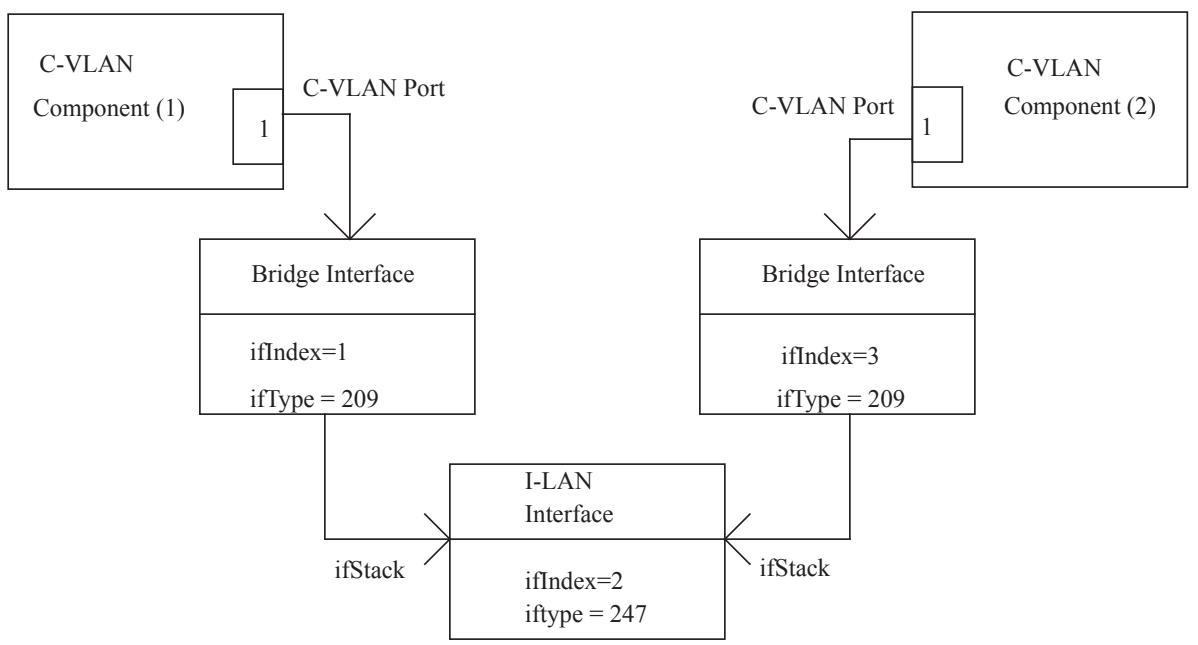
Figure 17-1—C-VLAN component internal LAN managed system
17.3.2.3 FDB for IEEE 802.1D Bridges
The tables needed to explicitly manage the FDB for IEEE 802.1D Bridges have been removed from the IEEE8021-BRIDGE-MIB. There were separate tables for this function in the original IETF MIBs, but these duplicate tables in the IEEE8021-QBRIDGE MIB and are not needed.
As a result, single FDB implementations, like IEEE Std 802.1D, should just implement the ieee8021QBridgeTpFdbTable with an ieee8021QBridgeFdbId of 1, and setting any VID indices to 0.
17.3.3 Relationship of the IEEE8021-RSTP MIB to other MIB modules
The objects in the RSTP MIB supplement those defined in the BRIDGE MIB.
The original IETF BRIDGE-MIB [RFC1493] and its SMIv2-compliant version [RFC4188] have been replaced by 17.7.2. Besides using different prefix names for modules, an additional index was added to allow use of the RSTP MIB module in PBB.
17.3.4 Relationship of the IEEE8021-Q-BRIDGE-MIB to other MIB modules
17.3.4.1 Relationship to the IF-MIB
This standard assumes the interpretation of the Interfaces Subtree to be in accordance with the IF-MIB [RFC2863], which states that the interfaces table (ifTable) contains information on the managed resource’s interfaces and that each sublayer below the internetwork layer of a network interface is considered an interface.
This standard does not make any assumption that within an entity, VIDs that are instantiated as an entry in dot1qVlanCurrentTable—either by management configuration through dot1qVlanStaticTable or by dynamic means (e.g., through MVRP)—are also represented by an entry in ifTable.
<!-- merged from 802.1Q_2014_0601-0800.md -->
Where an entity contains higher-layer protocol entities (e.g., IP-layer interfaces that transmit and receive traffic to/from a VLAN), these should be represented by an interface that represents the protocol entity and an interface of ifType l2vlan (135) with the ifStackTable indicating the stacking relationship between the two entities.
17.3.4.1.1 ifStackTable
In addition, the IF-MIB [RFC2863] defines a table 'ifStackTable' for describing the relationship between logical interfaces within an entity. It is anticipated that implementors will use this table to describe the binding of (for example) Link Aggregation Group (LAG) interfaces to physical Ports, although the presence of VLANs makes the representation less than perfect for showing connectivity. The ifStackTable cannot represent the full capability of this standard, since this standard makes a distinction between VLAN bindings on ingress to and egress from a Port. These relationships may or may not be symmetrical; whereas, Interface MIB Evolution assumes a symmetrical binding for transmit and receive. This makes it necessary to define other manageable objects for configuring which Ports are in the member set for which VIDs.
17.3.4.1.2 ifRcvAddressTable
This table contains all MAC addresses, unicast, multicast, and broadcast, for which an interface will receive packets and forward them up to a higher-layer entity for local consumption. Note that this does not include addresses for data-link layer control protocols such as STP, RSTP, MSTP, MMRP, or MVRP. The format of the address, contained in ifRcvAddressAddress, is the same as for ifPhysAddress.
This table does not include unicast or multicast addresses that are accepted for possible forwarding out some other Port. This table is explicitly not intended to provide a Bridge address filtering mechanism.
17.3.4.2 Relationship to IEEE8021-BRIDGE-MIB
This subclause defines how objects in the IEEE8021-BRIDGE-MIB module should be represented for devices that implement the extensions. Some of the old objects are less useful in such devices, but must still be implemented for reasons of backwards compatibility.
17.3.4.2.1 ieee8021BridgeBase subtree
This subtree contains objects that are applicable to all types of Bridges. Interpretation of this subtree is unchanged.
17.3.4.2.2 ieee8021BridgeTp subtree
This subtree contains objects that describe the entity’s state with respect to transparent bridging.
In a device operating with a single FDB, interpretation of this subtree is unchanged.
In a device supporting multiple FDBs, this subtree is interpreted as follows:
a) ieee8021BridgeTpLearnedEntryDiscards
The number of times that any of the FDBs became full.
b) ieee8021BridgeTpAgingTime
This applies to all FDBs.
c) ieee8021BridgeTpFdbTable
Report MAC addresses learned on each Port, regardless of which FDB they have been learned in. If an address has been learned in multiple databases on a single Port, report it only once. If an address has been learned in multiple databases on more than one Port, report the entry on any one of the valid Ports.
d) ieee8021BridgeTpPortTable
This table is Port-based and is not affected by multiple FDBs or multiple VIDs. The counters should include frames received or transmitted for all VIDs.
17.3.4.2.3 ieee8021BridgeStatic subtree
This optional subtree contains objects that describe the configuration of destination-address filtering.
In a device operating with a single FDB, interpretation of this subtree is unchanged.
In a device supporting multiple FDBs, this subtree is interpreted as follows:
a) ieee8021BridgeStaticTable
Entries read from this table include all static entries from all of the FDBs. Entries for the same MAC address and receive Port in more than one FDB must appear only once, since these are the indices of this table. This table should be implemented as read-only in devices that support multiple FDBs. Instead, write access should be provided through dot1qStaticUnicastTable and dot1qStaticMulticastTable, as defined in this standard.
17.3.4.2.4 Additions to the IEEE8021-BRIDGE-MIB
To supplement the BRIDGE-MIB, this module contains the following:
a) Support for multiple traffic classes and dynamic multicast filtering as per IEEE Std 802.1D.
b) Support for bridged VLANs as per IEEE Std 802.1Q.
c) Support for 64-bit versions of BRIDGE-MIB Port counters.
17.3.5 Relationship of the IEEE8021-PB-BRIDGE MIB to other MIB modules
To supplement the Q-BRIDGE-MIB, this module contains the following:
a) The Q-Bridge MIB directly supports VID translation. The original bidirectional VID translation of PB MIB is supported by the Q-Bridge MIB as well as separate ingress and egress VID translation.
b) Support for Provider Edge Bridges.
17.3.6 Relationship of the IEEE8021-MSTP-MIB to other MIB modules
The objects in the IEEE8021-MSTP-MIB supplement those defined in the IEEE8021-RSTP MIB.
17.3.7 Relationship of the IEEE8021-CFM-MIB to other MIB modules
17.3.7.1 Relationship to Interface MIB
Subclause 17.7.7 defines a CFM MIB module that supports 12.14 with the textual conventions imported from the TC MIB in 17.7.1. A system implementing the CFM MIB module in 17.7.7 shall also implement at least the System Group of the SNMPv2-MIB defined in IETF RFC 3418 and the Interfaces Group (the Interfaces MIB module, or IF-MIB) defined in IETF RFC 2863. The Interfaces Group has one conceptual row in a table for every interface in a system. Section 3.3 of IETF RFC 2863 defines hierarchical relationships among interfaces.
IETF RFC 2863 also requires that any MIB module that is an adjunct of the Interface Group clarify specific areas within the Interface MIB module. These areas were intentionally left vague in IETF RFC 2863 to avoid over-constraining the MIB, thereby precluding management of certain media types. These areas are clarified in other clauses that define the Bridge MIB modules. Even if a Bridge supports none of these, if it supports the CFM MIB module, and hence, the Interfaces Group, the clarifications from the other clauses shall be applied to the Interfaces Group. The relationship between IETF RFC 2863 and IETF RFC 3418 interfaces and Bridge Ports is also described in previous subclauses of 17.3. In addition, if both the CFM MIB module (17.7.7) and IEEE Std 802.1AX, are supported, a Bridge shall
a) Assign each IEEE 802.1AX Port in the aggregation its own conceptual row in the IETF RFC 2863 IF-MIB; and
b) Assign one conceptual row in the IETF RFC 2863 IF-MIB that references the aggregated Port. This may be the same as the interface identifying the Bridge Port. It shall not be the same as any of the IEEE 802.1AX Ports being aggregated.
17.3.7.2 IEEE8021-CFM-MIB and IEEE8021-CFM-V2-MIB
The inclusion of PBB (Clause 26) required the addition of additional indices to numerous tables in the CFM MIB. As a result, these tables are deprecated in the existing IEEE8021-CFM-MIB module and new reindexed tables are created in a second IEEE8021-CFM-V2-MIB module. Unchanged tables remain in the IEEE8021-CFM-MIB module. Specifically, groups with tables left unchanged are imported in the IEEE8021-CFM-V2-MIB module to appear in the compliance statement and new groups containing the new reindexed tables are added to the compliance statement.
The following tables are renamed:
dot1agPbbCfmStackTable
dot1agPbbCfmVlanTable
dot1agPbbCfmDefaultMdTable
dot1agPbbCfmConfigErrorListTable
dot1agPbbCfmMaCompTable
The new names are as follows:
ieee8021CfmStackTable
ieee8021CfmVlanTable
ieee8021CfmDefaultMdTable
ieee8021CfmConfigErrorListTable
ieee8021CfmMaCompTable
17.3.8 Relationship of the IEEE8021-PBB-MIB to other MIB modules
The IF-MIB, [RFC2863], requires that any MIB that is an adjunct of the IF-MIB clarify specific areas within the IF-MIB. These areas were intentionally left vague in the IF-MIB in order to avoid over-constraining the MIB, thereby precluding management of certain media types. The IF-MIB enumerates several areas that a media-specific MIB must clarify. Each of these areas is addressed in a following subclause. The implementor is referred to the IF-MIB in order to understand the general intent of these areas. The IF-MIB [RFC2863] defines managed objects for managing network interfaces.
A network interface is considered attached to a subnetwork. The term segment is used to refer to such a subnetwork, whether it be an Ethernet LAN, a ring, a WAN link, or even an SDH virtual circuit. Full support for PBB managed objects requires that the IF-MIB objects ifIndex, ifType, ifDescr, ifPhysAddress, and ifLastChange be implemented. Note that compliance to the current IF-MIB module requires additional objects and notifications to be implemented as specified in IETF RFC 2863.
The interpretation of the Interfaces Subtree is assumed to be in accordance with the IF-MIB, which states that the interfaces table (ifTable) contains information on the managed resource’s interfaces and that each sublayer below the internetwork layer of a network interface is considered an interface. Specifically, in the
PBB MIB module, the PIP index has been equated to an interface index (ifIndex). Therefore, when a PIP is created, a row is also created in the ifTable identified by the PIP’s ifIndex. The ifType of this interface is 248.22
In addition, the IF-MIB defines a table 'ifStackTable' for describing the relationship between logical interfaces within an entity. The ifStackTable cannot represent the full capability of this standard, since this standard makes a distinction between VLAN bindings on ingress to and egress from a Port. These relationships may or may not be symmetrical; whereas, Interface MIB Evolution assumes a symmetrical binding for transmit and receive. This makes it necessary to define other manageable objects for configuring which Ports are in the member set for which VIDs.
A PIP supports stacking through the ifStackTable. For external PIP interfaces, a PIP can be stacked on an Ethernet interface (ifType 6). If the PIP is internal, it can be stacked on an I-LAN interface to create a connection between an I-component and a B-component. The following is an example of how this process is completed:
a) Create I-component 1.
b) Create VIP 1 on component 1.
c) Create a PIP identified by ifIndex 1.
d) Associate VIP 1 on component 1 to the PIP.
e) Create an I-LAN interface identified with ifIndex 2.
f) Stack PIP 1 on the I-LAN interface 2.
g) Create B-component 2.
h) Create CBP 1 on component 2.
i) Associate CBP 1 on component 2 to I-LAN interface 2.
The result of the previous configuration steps are displayed in Figure 17-2.
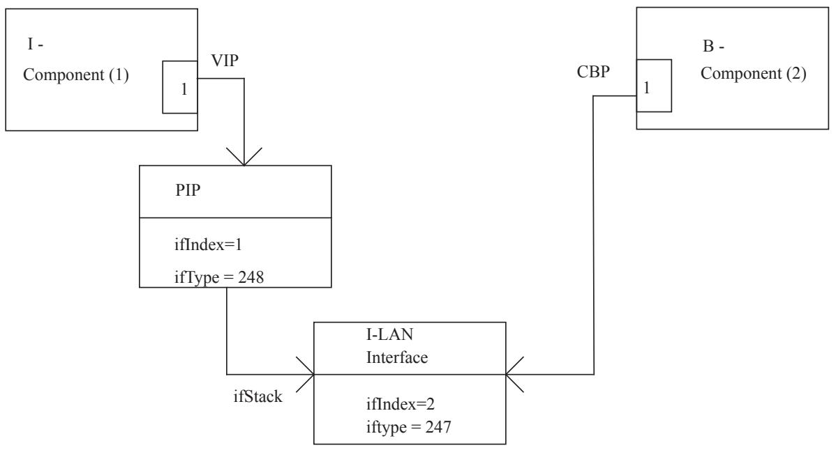
Figure 17-2—I/B-component internal LAN managed system
As a result, traffic can now be forwarded between I-component 1 and B-component 2 once a service is provisioned.
17.3.9 Relationship of the IEEE8021-DDCFM to other MIB modules
Subclause 17.7.9 defines the DDCFM MIB module that supports 12.17. A system implementing the DDCFM MIB module in 17.7.9 shall also implement at least the System Group of the SNMPv2-MIB defined in IETF RFC 3418 and Interfaces Group (the Interfaces MIB module, or IF-MIB) defined in IETF RFC 2863.
17.3.10 Relationship of the IEEE8021-PBBTE-MIB to other MIB modules
The IEEE8021-PBBTE-MIB is used to manage IB-BEBs that support additional PBB-TE functionality for the configuration of TESIs across provider backbone networks. The IEEE8021-PBBTE-MIB uses textual conventions and objects from the following MIB modules:
IEEE8021-TC-MIB
IEEE8021-BRIDGE-MIB
Q-BRIDGE-MIB
IEEE8021-Q-BRIDGE-MIB
The IEEE8021-PBBTE-MIB has the purpose of managing PBB-TE-specific functionality. As a PBB-TE IB-BEB is a specialized PBB IB-BEB with additional functionality, management of the system will also require that the system support the following Clause 17 MIB modules:
IEEE8021-BRIDGE-MIB
IEEE8021-CFM-MIB
IEEE8021-CFM-V2-MIB
IEEE8021-Q-BRIDGE-MIB
IEEE8021-MSTP-MIB
IEEE8021-PB-MIB
IEEE8021-PBB-MIB
Specifically, support of the IEEE-PBBTE-MIB requires that the system support the MIB and compliances in Table 17-28.
Table 17-28—PBB-TE required MIB compliances
<table><tr><td>MIB</td><td>Compliance</td></tr><tr><td>IEEE8021-PBB-MIB</td><td>ieee8021PbbWithPbbTeCompliance</td></tr><tr><td>IEEE8021-CFM-MIB</td><td rowspan="2">dot1agCfmWithPbbTeCompliance</td></tr><tr><td>IEEE8021-CFM-V2-MIB</td></tr></table>
17.3.11 Relationship of the TPMR MIB to other MIB modules
Subclause 17.7.11 defines a TPMR MIB module that supports the managed objects defined in 12.19. A system implementing the TPMR MIB module in 17.7.11 shall also implement at least the System Group of the SNMPv2-MIB defined in IETF RFC 3418 and the Interfaces Group (the Interfaces MIB module, or IF-MIB) defined in IETF RFC 2863. The Interfaces Group has one conceptual row in a table for every interface in a system. See Table 17-17 for the key objects from the System and Interfaces groups.
17.3.12 Relationship of the IEEE8021-FQTSS-MIB to other MIB modules
The IEEE8021-FQTSS-MIB provides objects that extend the core management functionality of a Bridge, as defined by the IEEE8021-BRIDGE-MIB (17.7.2), in order to support the additional management functionality needed when the FQTSS, as defined in Clause 34, is supported by the Bridge. As support of the objects defined in the IEEE8021-FQTSS-MIB also requires support of the IEEE8021-BRIDGE-MIB, the provisions of 17.3.2 apply to implementations claiming support of the IEEE8021-FQTSS-MIB.
17.3.13 Relationship of the IEEE802-CN-MIB to other MIB modules
17.3.13.1 Interface MIB
Subclause 17.7.13 defines a Congestion Notification MIB (IEEE802-CN-MIB) module that supports congestion notification with the textual conventions imported from the TC MIB in 17.7.13. A system implementing the IEEE802-CN-MIB module in 17.7.13 shall also implement at least the System Group of the SNMPv2-MIB defined in IETF RFC 3418 and the Interfaces Group (the Interfaces MIB module, or IF-MIB) defined in IETF RFC 2863. The Interfaces Group has one conceptual row in a table for every interface in a system. Section 3.3 of IETF RFC 2863 defines hierarchical relationships among interfaces. IETF RFC 2863 also requires that any MIB module that is an adjunct of the Interface Group clarify specific areas within the Interface MIB module. These areas were intentionally left vague in IETF RFC 2863 to avoid over-constraining the MIB, thereby precluding management of certain media types. These areas are clarified in other clauses that define the MIB modules in this standard. Even if a system supports none of these, if it supports the IEEE802-CN-MIB module, and hence, the Interfaces Group, the clarifications from the other clauses shall be applied to the Interfaces Group. The relationship between IETF RFC 2863 and IETF RFC 3418 interfaces and ports is also described in previous subclauses of 17.3. In addition, if both the IEEE802- CN-MIB module (17.7.13) and IEEE Std 802.1AX are supported, a Bridge component or end station may
a) Assign each port in the aggregation its own conceptual row in the IETF RFC 2863 IF-MIB; and
b) Assign one conceptual row in the IETF RFC 2863 IF-MIB that references the aggregated port. This can be the same as the interface identifying the port. It shall not be the same as any of the ports being aggregated.
17.3.13.2 IEEE8021-CFM-MIB and IEEE8021-CFM-V2-MIBs
Subclause 31.1 allows a system that supports either the dot1agCfmVlanTable from the IEEE8021-CFM-MIB module or the ieee8021CfmVlanTable from the IEEE8021-CFM-V2-MIB module to use those tables to select the vlan_identifier for a transmitted CNM.
17.3.14 Relationship of the IEEE8021-SRP-MIB to other MIB modules
The IEEE8021-SRP-MIB provides objects that extend the core management functionality of a Bridge, as defined by the IEEE8021-BRIDGE-MIB (17.7.2), in order to support the management functionality needed when the SRP extensions, as defined in Clause 35, are supported by the Bridge. As support of these objects defined in the IEEE8021-SRP-MIB also requires support of the IEEE8021-TC-MIB, IEEE8021-BRIDGE-MIB and IEEE8021-FQTSS-MIB, the provisions of 17.3.2 apply to implementations claiming support of the IEEE8021-SRP-MIB.
17.3.15 Relationship of the IEEE8021-MVRPX-MIB to other MIB modules
The IEEE8021-MVRPX-MIB, because it adds variables to the ieee8021BridgeBasePortEntry in the IEEE8021-BRIDGE-MIB, depends upon that MIB. It also imports items from the SNMPv2-SMI, SNMPv2- TC, and SNMPv2-CONF MIBs, and requires the systemGroup of the SNMPv2-MIB for conformance.
17.3.16 Relationship of the IEEE8021-MIRP-MIB to other MIB modules
The IEEE8021-MIRP-MIB, because it extends the variables in the IEEE8021-PBB-MIB (17.7.8), depends upon that MIB. Because it adds a variable to the ieee8021BridgeBasePortEntry in the IEEE8021-BRIDGE-MIB, it also depends upon that MIB. It also imports items from the SNMPv2-SMI, SNMPv2-TC, SNMPv2- CONF and Q-BRIDGE-MIB MIBs, and requires the systemGroup of the SNMPv2-MIB for conformance.
17.3.17 Relationship of the PFC MIB to other MIB modules
Subclause 17.7.13 defines a PFC MIB module. A system implementing the PFC MIB module in 17.7.13 shall also implement at least the System Group of the SNMPv2-MIB defined in IETF RFC 3418 and the Interfaces Group (the Interfaces MIB module, or IF-MIB) defined in IETF RFC 2863. The Interfaces Group has one conceptual row in a table for every interface in a system. Section 3.3 of IETF RFC 2863 defines hierarchical relationships among interfaces. IETF RFC 2863 also requires that any MIB module that is an adjunct of the Interface Group clarify specific areas within the Interface MIB module. These areas were intentionally left vague in IETF RFC 2863 to avoid over constraining the MIB, thereby precluding management of certain media types. These areas are clarified in other clauses which define the MIB modules in this standard. Even if a system supports none of these, if it supports the PFC MIB module, and hence, the Interfaces Group, the clarifications from the other clauses shall be applied to the Interfaces Group. The relationship between IETF RFC 2863 and IETF RFC 3418 interfaces and ports is also described in previous subclauses of 17.3.
17.3.18 Relationship of the IEEE8021-TEIPS-MIB to other MIB modules
The IEEE8021-TEIPS-MIB is used to manage IB-BEBs and BCBs that support IPS functionality. The IEEE8021-TEIPS-MIB uses textual conventions and objects from the following MIB modules:
IEEE8021-TC-MIB
IEEE8021-BRIDGE-MIB
The IEEE8021-TEIPS-MIB has the purpose of managing IPS in PBB-TE Region (26.11). Thus, use of the IEEE8021-TEIPS-MIB requires that the system support the same set of MIB modules specified within 17.3.10 and requires the compliances described by Table 17-21.
17.3.19 Relationship of the of the IEEE8021-SPB-MIB to other MIB modules
The IEEE8021-SPB-MIB, because it provides mainly control plane functions and reuses VLANs in the Q-BRIDGE-MIB depends on that MIB. It also imports items from the SNMPv2-SMI, SNMPv2-TC, IF-MIB and IEEE8021-TC-MIB, and requires SNMPv2-CONF for conformance.
17.3.20 Relationship of the IEEE8021-EVB-MIB to other MIB modules
The IEEE8021-EVB-MIB provides objects that extend the core management functionality of a Bridge, as defined by the IEEE8021-BRIDGE-MIB (17.7.2), in order to support the management functionality needed for EVB (5.23, 5.24), as defined in Clause 40, Clause 41, Clause 42, and Clause 43. As support of the objects defined in the IEEE8021-EVB-MIB also requires support of the IEEE8021-TC-MIB and IEEE8021-BRIDGE-MIB, the provisions of 17.3.2 apply to implementations claiming support of the IEEE8021-EVB-MIB.
17.3.21 Relationship of the of the IEEE8021-ECMP-MIB to other MIB modules
The IEEE8021-ECMP-MIB extends SPBM functionality and therefore is closely related to the IEEE8021-SPB-MIB and IEEE8021-PBB-MIB. For example, it includes configuration for an optional
ISIS-SPB sub-TLV for the ECMP ECT Algorithm (28.12.6.1) and configuration for flow filtering on PNPs and CBPs (44.2.2).
Because it provides control functions related to VIDs, it depends on the Q-BRIDGE-MIB. It also augments tables defined in the IEEE8021-Q-BRIDGE-MIB (adding the ability to read the FDB Port Map for an individual address and adding TTL discard statistics). It also imports items from the SNMPv2-SMI, SNMPv2-TC, and IEEE8021-TC-MIB and requires SNMPv2-CONF for conformance.
17.4 Security considerations
SNMP versions prior to SNMPv3 did not include adequate security. Even if the network itself is secure (for example, by using IPsec), there is no control about who on the secure network is allowed to access and GET/ SET (read/change/create/delete) the objects in these MIB modules.
It is recommended that implementers consider the security features as provided by the SNMPv3 framework (see IETF RFC 3410 (2002), section 8), including full support for the SNMPv3 cryptographic mechanisms (for authentication and privacy).
Further, deployment of SNMP versions prior to SNMPv3 is not recommended. Instead, it is recommended to deploy SNMPv3 and to enable cryptographic security. It is then a customer/operator responsibility to ensure that the SNMP entity giving access to an instance of these MIB modules is properly configured to give access to the objects only to those principals (users) that have legitimate rights to indeed GET or SET (change/create/delete) them.
17.4.1 Security considerations of the IEEE8021-TC-MIB
This module does not define any management objects. Instead, it defines a set of textual conventions that may be used by other MIB modules to define management objects. Meaningful security considerations are contained in the following subclauses that describe security considerations for other MIB modules that define management objects with a SYNTAX of any of these textual conventions.
17.4.2 Security considerations of the IEEE8021-BRIDGE-MIB
There are a number of management objects defined in the IEEE8021-BRIDGE-MIB module that have a MAX-ACCESS clause of read-write and/or read-create. Such objects may be considered sensitive or vulnerable in some network environments. The support for SET operations in a nonsecure environment without proper protection can have a negative effect on network operations.
Some of the readable objects in this MIB module (i.e., objects with a MAX-ACCESS other than notaccessible) may be considered sensitive or vulnerable in some network environments. It is thus important to control all types of access (including GET and/or NOTIFY) to these objects and possibly to even encrypt the values of these objects when sending them over the network via SNMP.
The following tables and objects in the IEEE8021-BRIDGE-MIB can be manipulated to interfere with the operation of priority classes. This could, for example, be used to force a reinitialization of state machines, thus causing network instability. Another possibility would be for an attacker to override established policy on Port priorities, thus giving a user (or an attacker) unauthorized preferential treatment.
ieee8021TrafficClassesEnabled
ieee8021GmrpStatus
ieee8021PortPriorityTable
ieee8021UserPriorityRegenTable
ieee8021TrafficClassTable ieee8021PortGarpTable ieee8021PortGmrpTable
a) The writable object ieee8021BridgeTpAgingTime controls how fast dynamically-learned forwarding information is aged out. Setting this object to a large value may simplify FDB overflow attacks. Setting this object to too small a value may compromise the throughput of the network by causing excessive flooding.
b) The writable ieee8021BridgeStaticTable provides a filtering mechanism controlling to which Ports frames originating from a specific source may be forwarded. Write access to this table can be used to turn provisioned filtering off or to add filters to prevent rightful use of the network.
Some of the readable objects in this MIB module (i.e., objects with a MAX-ACCESS other than notaccessible) may be considered sensitive or vulnerable in some network environments. It is thus important to control all types of access (including GET and/or NOTIFY) to these objects and possibly to even encrypt the values of these objects when sending them over the network via SNMP. These tables and objects and their sensitivity/vulnerability are described as follows:
The objects ieee8021DeviceCapabilities and ieee8021PortCapabilitiesTable in the IEEE8021-P-BRIDGE-MIB could be used by an attacker to determine which attacks might be useful to attempt against a given device.
The readable objects defined in the IEEE8021-BRIDGE-MIB module provide information about the topology of a bridged network and the attached active stations. The addresses listed in the ieee8021BridgeTpFdbTable usually reveal information about the manufacturer of the MAC hardware, which can be useful information for mounting other specific attacks.
The two notifications, newRoot and topologyChange, are emitted during spanning tree computation and may trigger management systems to inspect the status of Bridges and to recompute internal topology information. Hence, forged notifications may cause management systems to perform unnecessary computations and to generate additional SNMP traffic directed to the Bridges in a network. Therefore, forged notifications may be part of a denial of service attack.
17.4.3 Security considerations of the IEEE8021-SPANNING-TREE MIB
There are a number of management objects defined in this MIB module with a MAX-ACCESS clause of read-write and/or read-create. Such objects may be considered sensitive or vulnerable in some network environments. The support for SET operations in a nonsecure environment without proper protection can have a negative effect on network operations. These tables and objects and their sensitivity/vulnerability are described below.
Writable objects that could be misused to cause network delays and spanning tree instabilities include
ieee8021SpanningTreeVersion ieee8021SpanningTreeRstpTxHoldCount ieee8021SpanningTreeRstpPortProtocolMigration ieee8021SpanningTreeRstpPortAdminEdgePort ieee8021SpanningTreeRstpPortAdminPathCost ieee8021SpanningTreeRstpPortAdminPointToPoint
Some of the readable objects in this MIB module (i.e., objects with a MAX-ACCESS other than notaccessible) may be considered sensitive or vulnerable in some network environments. It is thus important to control all types of access (including GET and/or NOTIFY) to these objects and possibly to even encrypt the values of these objects when sending them over the network via SNMP. These tables and objects and their sensitivity/vulnerability are described below:
ieee8021SpanningTreeVersion could be read by an attacker to identify environments containing applications or protocols that are potentially sensitive to RSTP mode.
The writable objects
ieee8021SpanningTreePriority
ieee8021SpanningTreeBridgeMaxAge
ieee8021SpanningTreeBridgeHelloTime
ieee8021SpanningTreeBridgeForwardDelay
ieee8021SpanningTreePortPriority
ieee8021SpanningTreePortEnable
ieee8021SpanningTreePortPathCost
influence the spanning tree protocol. Unauthorized write access to these objects can cause the spanning tree protocol to compute other default topologies or it can change the speed in which the spanning tree protocol reacts to failures.
17.4.4 Security considerations of the IEEE8021-Q-BRIDGE-MIB
There are a number of management objects defined in this MIB module with a MAX-ACCESS clause of read-write and/or read-create. Such objects may be considered sensitive or vulnerable in some network environments. The support for SET operations in a nonsecure environment without proper protection can have a negative effect on network operations. These tables and objects and their sensitivity/vulnerability are described below.
The following tables and objects in the IEEE8021-Q-BRIDGE-MIB could be manipulated to interfere with the operation of VLANs. This could, for example, be used to force a reinitialization of state machines to cause network instability, or to change the forwarding and filtering policies.
ieee8021GvrpStatus
ieee8021ForwardAllTable
ieee8021StaticUnicastTable
ieee8021StaticMulticastTable
ieee8021VlanStaticTable
ieee8021PortVlanTable
ieee8021LearningConstraintsTable
ieee8021ProtocolGroupTable
ieee8021ProtocolPortTable
Some of the readable objects in this MIB module (i.e., objects with a MAX-ACCESS other than notaccessible) may be considered sensitive or vulnerable in some network environments. It is thus important to control all types of access (including GET and/or NOTIFY) to these objects and possibly to even encrypt the values of these objects when sending them over the network via SNMP. These tables and objects and their sensitivity/vulnerability are described below.
The following read-only tables and objects in the IEEE8021-Q-BRIDGE-MIB could be used by an attacker to determine which attacks might be useful to attempt against a given device, could be used by an attacker to detect whether their attacks are being blocked or filtered, or could be used to understand the logical topology of the network.
ieee8021MaxVlanID
ieee8021MaxSupportedVlans
ieee8021NumVlans
ieee8021FdbTable
ieee8021TpFdbTable
ieee8021TpPortGroupTable
ieee8021VlanCurrentTable
ieee8021PortVlanStatisticsTable
17.4.5 Security considerations of the IEEE8021-PB-MIB
There are a number of management objects defined in this MIB module with a MAX-ACCESS clause of read-write and/or read-create. Such objects may be considered sensitive or vulnerable in some network environments. The support for SET operations in a non-secure environment without proper protection can have a negative effect on network operations. These tables and objects and their sensitivity/vulnerability are described below.
The following tables and objects in the PB-MIB could be manipulated to interfere with the operation of VLANs. This could, for example, be used to force a reinitialization of state machines to cause network instability, or to change the forwarding and filtering policies.
ieee8021PbProviderBridgePortTable
ieee8021PbVidTranslationTable
ieee8021PbCVidRegistrationTable
ieee8021PbEdgePortTable
ieee8021PbInternalInterfaceTable
17.4.6 Security considerations of the IEEE8021-MSTP-MIB
There are a number of management objects defined in this MIB module with a MAX-ACCESS clause of read-write and/or read-create. Such objects may be considered sensitive or vulnerable in some network environments. The support for SET operations in a nonsecure environment without proper protection can have a negative effect on network operations. These tables and objects and their sensitivity/vulnerability are described below.
Writable objects that could be misused to cause network delays and spanning tree instabilities include the following:
ieee8021CistEnableBPDURx
ieee8021CistEnableBPDUTx
ieee8021CistPortAdminEdgePort
ieee8021CistPortMacEnabled
ieee8021MstpPortPriority
ieee8021MstpPortPathCost
Some of the readable objects in this MIB module (i.e., objects with a MAX-ACCESS other than notaccessible) may be considered sensitive or vulnerable in some network environments. It is thus important to control all types of access (including GET and/or NOTIFY) to these objects and possibly to even encrypt the values of these objects when sending them over the network via SNMP. These tables and objects and their sensitivity/vulnerability are described below:
ieee8021SpanningTreeVersion could be read by an attacker to identify environments containing applications or protocols that are potentially sensitive to RSTP mode.
17.4.7 Security considerations of the IEEE8021-CFM-MIB
It is expected that, in some provider networks, management access to a Bridge can be granted, by an organization that owns and is responsible for the normal operations of the Bridge, to another organization that needs to configure and manage CFM entities in that Bridge. For example, a Provider could sell a service to a customer that connects sites in cities thousands of kilometers apart. That Provider might not have a physical presence in all of those cities (or any of them, for that matter) and therefore would need to contract with other Providers to supply a number of interconnected PBNs that together are able to offer the service to the customer. The relationship between the Provider and Owner is not necessarily cordial; there can be personal or financial incentives for misbehavior.
To support this scenario, the MIB module in 17.7.7 defines the Maintenance Domain table— dot1agCfmMdTable. Each row (dot1agCfmMdEntry) in this table corresponds to one Maintenance Domain managed object (12.14.5). A Maintenance Domain managed object can be created, read, and written by the Bridge’s Owner. More limited access to that object can be granted to another Provider, who thereby becomes that Maintenance Domain’s administrator. Associated with each row in the Maintenance Domain table are any number of rows (dot1agCfmMaNetEntry and dot1agCfmMaCompEntry) in the MA tables— dot1agCfmMaNetTable and dot1agCfmMaCompTable. Each of the paired rows in these two tables corresponds to a Maintenance Association managed object (12.14.6). A Maintenance Domain administrator has the ability to create and alter these rows. Additional MIB tables are defined in 17.7.7 that correspond to the Maintenance Domain list managed object (12.14.1), the CFM Stack managed object (12.14.2), and the Default MD Level managed object (12.14.3), all of which can be used by an Owner of the Bridge, but not by a Maintenance Domain administrator.
The SNMPv3 framework (IETF STD 62) defines a securityName, which provides for secure identification of a user (or group of users) via an SNMPv3 Security Model. For ease of reference in this present standard, the “Owner” of a system (in particular, a Bridge) is defined as a user whose “MIB view” includes READ-WRITE access to the System Group of the SNMPv2-MIB (IETF RFC 3418). A Management Domain administrator is then a user whose MIB view includes more limited access to the Maintenance Domain managed object, and full READ-WRITE access to its subordinate Maintenance Association managed objects (12.14.6), each of which is a pair of rows (dot1agCfmMaNetEntry and dot1agCfmMaCompEntry) in the two tables—dot1agCfmMaNetTable and dot1agCfmMaCompTable.
A Bridge can support IETF STD 62 (SNMPv3) in order to provide a secure means for confining access by Management Domain administrators to their corresponding Maintenance Association managed objects, and to prevent inappropriate access to the rest of the Bridge’s management objects. If the SNMPv3 framework is not implemented in a Bridge, an Owner is defined, imprecisely, as an administrator of the Bridge, and a Management Domain administrator (even less precisely) as an administrator of one Management Domain.
Therefore, it is recommended that the implementors consider the security features as provided by the SNMPv3 framework, including full support for the SNMPv3 cryptographic mechanisms (for authentication and privacy). Specifically, a Bridge can use the User-Based Security Model, IETF RFC 3414, and/or the View-Based Access Control Model, IETF RFC 3415, for controlling access to the CFM managed objects. It is then a customer/user responsibility to ensure that the SNMP agent giving access to an instance of this MIB is properly configured to give access to the objects only to those principals (users) that have legitimate rights to GET or SET (change/create/delete) them.
The control of access by Providers to other MIB modules, for example, the Interface Group, is not specified by this standard.
There are a number of management objects defined in this MIB module with a MAX-ACCESS clause of read-write and/or read-create. Such objects may be considered sensitive or vulnerable in some network environments. The support for SET operations in a nonsecure environment without proper protection can have a negative effect on network operations. Table 17-29 lists the MIB tables and objects and their sensitivity/vulnerability.
Table 17-29—Sensitive managed objects: tables and notifications
<table><tr><td>Table or object</td><td>Reason for sensitivity to security considerations</td></tr><tr><td>dot1agCfmDefaultMdTable, dot1agCfmVlanTable</td><td>The integrity of the spanning tree(s) running in a network is dependent on certain configuration parameters, especially Static VLAN Registration Entries (8.8.2). The assignment of VIDs to particular service instances, and hence to MAs, is controlled by the administrator responsible for the integrity of the spanning tree, namely the Owner of the Bridge.</td></tr><tr><td>dot1agCfmMdTable, dot1agCfmMaNetTable, dot1ag-CfmMaCompTable, dot1agCfmVlanTable, dot1agCfmMaMepListTable, dot1agCfmMepTable, dot1agCfmMepDbTable, dot1agCfmLtrTable, dot1agCfmFaultAlarm</td><td>The business relationships among the various Maintenance Domain administrators, and between them and the Owner of the Bridge, are not defined by this standard. The ability of one Maintenance Domain administrator to identify another, or even detect the presence of another Maintenance Domain administrator, in the same Bridge, may jeopardize those business relationships. The CFM MIB module separates objects by Maintenance Domain so that the Bridge Owner can ensure that management by one Maintenance Domain administrator does not conflict with management by another.</td></tr></table>
There is no detailed list in this standard of all vulnerable objects with a MAX-ACCESS clause of read-write or read-create and of the security threats associated to their intentional or unintentional manipulation by write actions. The reason is that this standard takes the approach that objects within a maintenance domain are protected as if in a “walled garden,” accessible only by administrators authorized for the respective Maintenance Domains. See Figure 12-1 for an illustration of this concept.
The only exceptions to this approach are the read-create MIB objects that define the maintenance domains themselves and their capabilities. The vulnerabilities associated with these objects are shown in Table 17-30.
Table 17-30—Sensitive managed objects: variables in dot1agCfmMdTable
<table><tr><td>Object</td><td>Reason for sensitivity to security considerations</td></tr><tr><td>dot1agCfmMdFormat, dot1agCfmMd-Name</td><td>An intentional or accidental write operation on these objects may lead to the modification of the identifiers of the Maintenance Domains and would impact the capacity of existing administrators to identify and manage the entities within those Maintenance Domains.</td></tr><tr><td>dot1agCfmMdMdLevel</td><td>An intentional or accidental write operation on this object may impact the CFM operations on the Maintenance Domain by altering the MD Level associated with the Maintenance Domain.</td></tr><tr><td>dot1agCfmMdMhfCreation</td><td>An intentional or accidental write operation on this object may impact the capabilities for creating MIP Half Functions (MHFs) in the Maintenance Domain.</td></tr></table>
17.4.8 Security considerations of the IEEE8021-PBB-MIB
There are a number of management objects defined in this MIB module with a MAX-ACCESS clause of read-write and/or read-create. Such objects may be considered sensitive or vulnerable in some network environments. The support for SET operations in a nonsecure environment without proper protection can have a negative effect on network operations. These tables and objects and their sensitivity/vulnerability are described next.
The following tables and objects in the PBB MIB could be manipulated to interfere with the operation of PBBs. This could, for example, be used to force a reinitialization of state machines to cause network instability, or changing the forwarding and filtering policies. The following are vulnerable writable objects from the IEEE8021-PBB-MIB:
ieee8021PbbVipISid
ieee8021PbbPipVipMap
In addition, the following are vulnerable tables from the IEEE8021-PBB-MIB:
ieee8021PbbCBPServiceMappingTable
ieee8021PbbPipPriorityTable
ieee8021PbbVipToPipMappingTable
ieee8021PbbCbpTable
Some of the readable objects in this MIB module (i.e., objects with a MAX-ACCESS other than notaccessible) may be considered sensitive or vulnerable in some network environments. It is thus important to control all types of access (including GET and/or NOTIFY) to these objects and possibly to even encrypt the values of these objects when sending them over the network via SNMP.
The following read-only tables and objects in this MIB could be used by an attacker to determine which attacks might be useful to attempt against a given device, or could be used to understand the logical topology of the network:
ieee8021PbbBackboneEdgeBridgeAddress
ieee8021PbbVipPipIfIndex
ieee8021PbbISidToVipComponentId
ieee8021PbbISidToVipPort
17.4.9 Security considerations of the IEEE8021-DDCFM-MIB
There are a number of management objects defined in DDCFM MIB module with a MAX-ACCESS clause of read-write and/or read-create. Such objects may be considered sensitive or vulnerable in some network environments. The support for SET operations in a nonsecure environment without proper protection can have a negative effect on network operations. Table 17-31 lists the MIB tables and objects and their sensitivity/vulnerability.
Table 17-31—Sensitive managed objects (of DDCFM): tables and notifications
<table><tr><td>Table or object</td><td>Reason for sensitivity to security considerations</td></tr><tr><td>ieee8021DdcfmRr</td><td>Once created and activated, ieee8021DdcfmRr can intercept selected data frames traversing through a Bridge interface, and send its copy encapsulated in RFM header to a specific destination within the maintenance domain. The action can create extra traffic within the maintenance domain.</td></tr><tr><td>ieee8021DdcfmDr</td><td>Once created and activated, ieee8021DdcfmDr will decapsulate received SFM and send the decapsulated data frame to location specified by the data frame's destination_address. This action practically injects specific traffic into the network.</td></tr><tr><td>ieee8021DdcfmSFMOriginator</td><td>Once created and activated, ieee8021DdcfmSFMOriginator injects SFMs into the maintenance domain. However, if the corresponding ieee8021DdcfmDr is not activated, the received SFMs are dropped. Therefore, ieee8021DdcfmSFMOriginator is less sensitive than the corresponding ieee8021DdcfmDr.</td></tr></table>
Some of the readable objects in this MIB module (i.e., objects with a MAX-ACCESS other than notaccessible) may be considered sensitive or vulnerable in some network environments. It is thus important to control even GET and/or NOTIFY access to these objects and possibly to even encrypt the values of these objects when sending them over the network via SNMP. Table 17-32 lists the MIB tables and objects that are sensitive to read.
Table 17-32—Sensitive managed objects (of DDCFM) for read
<table><tr><td>Table or object</td><td>Reason for sensitivity to security considerations</td></tr><tr><td>ieee8021DdcfmRFMReceiver</td><td>Once created, ieee8021DdcfmRFMReceiver can receive the RFM, which encapsulate actual data frame that could be sensitive and need to be protected. It is very important to control the GET operation on this object.</td></tr></table>
17.4.10 Security considerations of the IEEE8021-PBBTE-MIB
There are a number of management objects defined in this MIB module with a MAX-ACCESS clause of read-write and/or read-create. Such objects may be considered sensitive or vulnerable in some network environments. The support for SET operations in a nonsecure environment without proper protection can have a negative effect on network operations. These tables and objects and their sensitivity/vulnerability are described below.
The following tables and objects in the PBB MIB could be manipulated to interfere with the operation of IB PBBs. This could, for example, be used to force a reinitialization of state machines to cause network instability, or changing the forwarding and filtering policies. The following are all the writable objects from the IEEE8021-PBB-MIB:
ieee8021PbbTeProtectionGroupListWorkingMA ieee8021PbbTeProtectionGroupListProtectionMA ieee8021PbbTeProtectionGroupListRowStatus ieee8021PbbTeTesiComponent ieee8021PbbTeTesiBridgePort ieee8021PbbTeProtectionGroupConfigCommandAdmin
ieee8021PbbTeProtectionGroupConfigWTR
ieee8021PbbTeProtectionGroupConfigHoldOff
ieee8021PbbTeProtetcionGroupConfigNotifyEnable
ieee8021PbbTeProtectionGroupISidGroupId
ieee8021PbbTeProtectionGroupISidRowStatus
ieee8021PbbTeBridgeStaticForwardAnyUnicastTable
ieee8021PbbTeBridgeStaticForwardAnyUnicastEgressPorts
ieee8021PbbTeBridgeStaticForwardAnyUnicastForbiddenPorts
17.4.11 Security considerations of the TPMR MIB
There are a number of management objects defined in this MIB module with a MAX-ACCESS clause of read-write and/or read-create. Such objects may be considered sensitive or vulnerable in some network environments. The support for SET operations in a nonsecure environment without proper protection can have a negative effect on network operations. These tables and objects and their sensitivity/vulnerability are described below.
The following object in the SNMPv2-MIB could be manipulated to interfere with the operation of a management system and its ability to recognize and manage a TPMR device.
sysName
The following object in the SNMPv2-MIB could be manipulated to interfere with the operation of a management system and its ability to recognize and manage a TPMR Port.
ifName
The following objects in the TPMR-MIB could be manipulated to interfere with the operation of MSP on a TPMR Port and, for example, be used to cause network instability.
ieee8021TpmrMspLinkNotify
ieee8021TpmrMspLinkNotifyWait
ieee8021TpmrMspLinkNotifyRetry
ieee8021TpmrMspMacNotify
ieee8021TpmrMspMacNotifyTime
ieee8021TpmrMspMacRecoverTime
17.4.12 Security considerations of the IEEE8021-FQTSS-MIB
There are a number of management objects defined in the IEEE8021-FQTSS-MIB module that have a MAX-ACCESS clause of read-write and/or read-create. Such objects may be considered sensitive or vulnerable in some network environments. The support for SET operations in a nonsecure environment without proper protection can have a negative effect on network operations.
Some of the readable objects in this MIB module (i.e., objects with a MAX-ACCESS other than notaccessible) may be considered sensitive or vulnerable in some network environments. It is thus important to control all types of access (including GET and/or NOTIFY) to these objects and possibly to even encrypt the values of these objects when sending them over the network via SNMP.
The following tables and objects in the IEEE8021-FQTSS-MIB can be manipulated to interfere with the operation of the forwarding and queuing mechanisms in a manner that would be detrimental to the transmission of time-sensitive streams:
ieee8021FqtssDeltaBandwidth
ieee8021FqtssAdminIdleSlopeMs
ieee8021FqtssAdminIdleSlopeLs
ieee8021FqtssTxSelectionAlgorithmID
ieee8021FqtssPriorityRegenOverride
a) ieee8021FqtssDeltaBandwidth can be manipulated to reduce the amount of bandwidth available to a given SR class.
b) ieee8021FqtssAdminIdleSlopeMs and ieee8021FqtssAdminIdleSlopeLs can be manipulated to change the overall amount of bandwidth available to stream traffic on a Port, in a network where SRP is not used for stream reservations.
c) ieee8021FqtssTxSelectionAlgorithmID can be manipulated in order to apply the wrong transmission selection algorithm to a traffic class that was being used by stream traffic.
d) ieee8021FqtssPriorityRegenOverride can be manipulated to disrupt stream traffic within an SRP domain with non-stream traffic entering from outside the SRP domain boundary.
17.4.13 Security considerations of the Congestion Notification MIB
There are a number of management objects defined in the IEEE8021-MIRP-MIB module with a MAX-ACCESS clause of read-write and/or read-create. Such objects may be considered sensitive or vulnerable in some network environments. The support for SET operations in a nonsecure environment without proper protection can have a negative effect on network operations. These tables and objects and their sensitivity/ vulnerability are described in the paragraphs that follow.
Improper manipulation of certain tables and objects can result in the misidentification of the boundaries of CNDs (30.6). Any such errors can result in the following problems:
a) Frames not originated through an RP (31.2.2.2) can pass through CPs (31.1.1). The inability to throttle these frames via CNMs (33.3) can cause legitimate, RP-originated frames to experience unacceptably high loss rates.
b) Frames not originating through an RP (31.2.2.2) can pass through queues in the bridged network that are not CPs (31.1.1), where they can encounter uncontrolled congestion. This can cause those frames to experience unacceptably high loss rates.
c) The CN-TAG (30.5) in a data frame or CNM can be improperly discarded. This can cause that CNM, or a CNM resulting from the data frame, to be discarded by the end station that sourced the frame. As a result, that flow, and all flows passing through the same CPs, can experience unacceptably high loss rates.
d) The CN-TAG in a data frame or CNM can be improperly retained. This can result in a failure of two end stations to communicate, because the receiving end station is unable to process frames with CN-TAGs.
The following tables and objects in the IEEE8021-MIRP-MIB can cause such CND boundary identification errors:
ieee8021CnGlobalMasterEnable
ieee8021CnComPriDefModeChoice
ieee8021CnComPriAdminDefenseMode
ieee8021CnComPriCreation
ieee8021CnComPriLldpInstanceChoice
ieee8021CnComPriLldpInstanceSelector
ieee8021CnComPriRowStatus
ieee8021CnPortPriDefModeChoice
ieee8021CnPortPriAdminDefenseMode
ieee8021CnPortPriLldpInstanceChoice
ieee8021CnPortPriLldpInstanceSelector
Improper manipulation of certain other objects can result in assigning a data frame or CNM to the incorrect priority. This can result in the affected data streams experiencing loss rates that are either higher or lower than expected by the network administrator. Lower than expected loss rates for one data stream can cause higher than expected loss rates for other streams. These affects are typically, but not universally, less severe than the loss rate anomalies caused by CND boundary misidentification. The following variables can cause improper priority assignment:
ieee8021CnGlobalCnmTransmitPriority
ieee8021CnComPriAlternatePriority
ieee8021CnPortPriAlternatePriority
Improper manipulation of the remainder of the read-write and read-create objects can cause the congestion notification algorithm to operate in ways not intended by the network administrator. This can result in excessively high data frame loss rates and/or low link utilization rates. These variables are the following:
ieee8021CnCpQueueSizeSetPoint
ieee8021CnCpFeedbackWeight
ieee8021CnCpMinSampleBase
ieee8021CnCpMinHeaderOctets
ieee8021CnRpPortPriMaxRps
ieee8021CnRpgEnable
ieee8021CnRpgTimeReset
ieee8021CnRpgByteReset
ieee8021CnRpgThreshold
ieee8021CnRpgMaxRate
ieee8021CnRpgAiRate
ieee8021CnRpgHaiRate
ieee8021CnRpgGd
ieee8021CnRpgMinDecFac
ieee8021CnRpgMinRate
Unintended access to any of the readable tables or variables in the IEEE8021-MIRP-MIB alerts the reader that congestion notification is configured, and (for all tables and variables except those in the ieee8021CnGlobalTable and ieee8021CnCpidToInterfaceTable) on which priority value or values congestion notification is configured. This information can suggest to an attacker what applications are being run, and thus suggest application-specific attacks, or to enable the attacker to detect whether their attacks are successful. It is thus important to control even GET and/or NOTIFY access to these objects and possibly to even encrypt the values of these objects when sending them over the network via SNMP.
17.4.14 Security considerations of the IEEE8021-SRP-MIB
The purpose of MSRP is to create reservations for various types of data streams, including audio/video (AV) content. Access to the objects within the IEEE8021-SRP-MIB module, whether they have MAX-ACCESS of read-write, read-create, or read-only, may reveal sensitive information in some network environments. Very serious health and safety situations could arise if MSRP was involved in configuring network resources for an emergency public safety announcement and the MSRP behavior of the bridged network was allowed to be modified unexpectedly.
With these considerations in mind it is thus important to control all types of access (including GET and/or NOTIFY) to these objects and possibly even encrypt their values when sending them over the network via SNMP.
The following tables and objects in the IEEE8021-SRP-MIB can be manipulated to interfere with the operation of the stream reservation mechanisms in a manner that would be detrimental to the transmission of the associated stream data:
ieee8021SrpBridgeBaseMsrpEnabledStatus
ieee8021SrpBridgeBaseMsrpTalkerPruning
ieee8021SrpBridgeBaseMsrpMaxFanInPorts
ieee8021SrpBridgeBaseMsrpLatencyMaxFrameSize
ieee8021SrpBridgePortMsrpEnabledStatus
ieee8021SrpBridgePortSrPvid
a) ieee8021SrpBridgeBaseMsrpEnabledStatus can be manipulated to enable or disable MSRP operations for the entire Bridge.
b) ieee8021SrpBridgeBaseMsrpTalkerPruning can be manipulated to stop the propagation of Talker attributes if Listeners are not configured to support Talker Pruning.
c) ieee8021SrpBridgeBaseMsrpMaxFanInPorts can be manipulated to set the number of ingress ports supporting streaming down to one, which would stop Talkers streams from coming in on any other port.
d) ieee8021SrpBridgeBaseMsrpLatencyMaxFrameSize can be manipulates to set a frame size that is so large or so small that it causes the Bridge to calculate unreasonable maximum latency.
e) ieee8021SrpBridgePortMsrpEnabledStatus can be manipulated to enable or disable MSRP on a particular port, perhaps allowing sensitive stream data to be sent to unacceptable devices.
ieee8021SrpBridgePortSrPvid can be manipulated to move Streams to a VLAN that has been blocked by management, thus disabling reception of the Stream by one or more Listeners.
17.4.15 Security considerations of the IEEE8021-MVRPX-MIB
The objects in IEEE8021-MVRPX-MIB could be manipulated to interfere with the operation of PBBs. Setting ieee8021MvrpxPortNewOnly, ieee8021MvrpxPortMvrpNewPropagated, or ieee8021MvrpxPortXmitZero to the wrong value could cause New messages to be transmitted when they should not be or suppressed when they should be transmitted. This can result in the FDB being flushed either too often or not at all, or in lost or spurious VLAN registrations. Extra New messages waste resources in the Bridge’s supervisory processor and can cause unnecessary flooding of data frames to unknown destinations, and lost New messages can prevent connectivity until the entries in the FDB time out. Lost or spurious VLAN registrations can cause the loss of connectivity for particular VLANs, or waste system resources transporting data frames to parts of the network where they are not needed.
17.4.16 Security considerations of the IEEE8021-MIRP-MIB
The following tables and objects in the IEEE8021-MIRP-MIB could be manipulated to interfere with the operation of PBBs. They could, for example, prevent Multiple I-SID Registration Protocol Data Units (MIRPDUs) from reaching their intended destinations, or cause them to reach unintended destinations. The former could result in temporary loss of service due to MAC address entries being timed out, instead of being flushed. The latter could result in excessive computation time taken by the PIPs or I-components unnecessarily receiving the MIRPDUs. The following are vulnerable writable objects from the IEEE8021- MIRP-MIB:
ieee8021MirpV2PortTable
ieee8021MirpV2PortEnabledStatus
ieee8021PbbMirpEnableStatus
ieee8021PbbMirpBvid
ieee8021PbbMirpDestSelector
ieee8021PbbMirpPnpEnable
ieee8021PbbMirpPnpPortNumber
17.4.17 Security considerations for the PFC MIB
One management object defined in the IEEE8021-PFC-MIB module has a MAXACCESS clause of readwrite. Such object can be considered sensitive or vulnerable in some network environments. The support for SET operations in a nonsecure environment without proper protection can have a negative effect on network operations. The management object is
PFCLinkDelayAllowance
Improper setting of this management object can result in improper network operations. If the value of this management object is too high, then PFC can be invoked excessively, negatively impacting the link bandwidth. If the value of this management object is too low, then PFC can be invoked too late and frame loss can occur.
17.4.18 Security considerations of the IEEE8021-TEIPS-MIB
There are a number of management objects defined in this MIB module with a MAX-ACCESS clause of read-write and/or read-create. Such objects may be considered sensitive or vulnerable in some network environments. The support for SET operations in a nonsecure environment without proper protection can have a negative effect on network operations. These tables and objects and their sensitivity/vulnerability are described below.
The following tables and objects in the TEIPS-MIB could be manipulated to interfere with the operation of PBBs. This could, for example, be used to force a reinitialization of state machines to cause network instability or to change the forwarding and filtering policies. The following are all the writable objects from the IEEE8021-TEIPS-MIB:
ieee8021TeipsV2Ipgid
ieee8021TeipsV2IpgWorkingMA
ieee8021TeipsV2IpgProtectionMA
ieee8021TeipsV2TesiId
ieee8021TeipsV2CandidatePsMA
ieee8021TeipsV2IpgConfigWTR
ieee8021TeipsV2IpgConfigHoldOff
ieee8021TeipsV2IpgConfigMWTR
17.4.19 Security considerations of the IEEE8021-SPB-MIB
There are a number of management objects defined in this MIB module with a MAX-ACCESS clause of read-write and/or read-create. Such objects may be considered sensitive or vulnerable in some network environments. The support for SET operations in a non-secure environment without proper protection can have a negative effect on network operations. These tables and objects and their sensitivity/vulnerability are described next.
ieee8021SpbMtidStaticEntryMtid
The following tables and objects in the SPB-MIB could be manipulated to interfere with the operation of Shortest Path Bridges. This could, for example, be used to misconfigure the network to cause loss of connectivity, or misconnect traffic. The following are vulnerable writable objects from the IEEE8021-SPB-MIB:
ieee8021SpbSys
ieee8021SpbSysAreaAddress
ieee8021SpbSysId
ieee8021SpbSysControlAddr
ieee8021SpbSysName
ieee8021SpbSysBridgePriority
ieee8021SpbMtidStaticTable
ieee8021SpbMtidStaticTableEntry
ieee8021SpbMTidStaticEntryMtidOverload
ieee8021SpbmBsiStaticTable
dot1agCfmMepSpbmEspTable
Some of the readable objects in this MIB module (i.e., objects with a MAX-ACCESS other than not accessible) may be considered sensitive or vulnerable in some network environments. It is thus important to control all types of access (including GET and/or NOTIFY) to these objects and possibly to even encrypt the values of these objects when sending them over the network via SNMP. The following read-only tables with there respective objects in this MIB could be used by an attacker to understand the logical topology of the network:
ieee8021SpbEctDynamicTable
ieee8021SpbAdjDynamicTable
ieee8021SpbTopNodeTable
ieee8021SpbTopEctTable
ieee8021SpbTopEdgeTable
17.4.20 Security considerations of the IEEE8021-EVB-MIB
The purpose of EVB is to coordinate VSIs within an EVB station with a data center network (DCN). In this environment the EVB station and the EVB Bridge may be under different management authorities. Access to the objects within the IEEE8021-EVB-MIB module of the EVB Bridge by the EVB station and access to objects within the IEEE8021-EVB-MIB module of the EVB station by the EVB Bridge may therefore need to be restricted.
Access to the objects within the IEEE8021-EVB-MIB module, whether they have MAX-ACCESS of readwrite, read-create, or read-only, can reveal sensitive information in some network environments. Very serious health and safety situations could arise if EVB systems were involved in configuring network resources for an emergency public safety announcement and the EVB Bridge system behavior of the bridged network was allowed to be modified unexpectedly.
With these considerations in mind, it is thus important to control all types of access (including GET and/or NOTIFY) to these objects. SNMP versions prior to SNMPv3 did not include adequate security. Even if the network itself is secure (for example, by using IPsec), there is no control about who on the secure network is allowed to access and GET/SET (read/change/create/delete) the objects in this MIB module.
It is recommended that implementers consider the security features as provided by the SNMPv3 framework (see IETF RFC 3410 (2002), section 8), including full support for the SNMPv3 cryptographic mechanisms (for authentication and privacy).
Further, deployment of SNMP versions prior to SNMPv3 is not recommended. Instead, it is recommended to deploy SNMPv3 and to enable cryptographic security. It is then a customer/operator responsibility to ensure that the SNMP entity giving access to an instance of this MIB module is properly configured to give access to the objects only to the principals (users) that have legitimate rights to indeed GET or SET (change/ create/delete) them.
There are a number of management objects defined in IEEE8021-EVB-MIB module with a MAX-ACCESS clause of read-write and/or read-create. Such objects may be considered sensitive or vulnerable in some network environments. The support for SET operations in a non-secure environment without proper protection can have a negative effect on network operations. Table 17-33 describes the tables and objects and their sensitivities/vulnerabilities.
Table 17-33—Sensitive managed objects (of EVB): tables and notifications
<table><tr><td>Table or object</td><td>Reason for sensitivity to security considerations</td></tr><tr><td>evbSysEvbLldpTxEnableevbSysEvbLldpManualevbSysEvbLldpGidCapable</td><td>The EVB TLV exchange controls how the VDP, ECP and reflective relay parameters are set. These parameters allow manual configurations of the EVB parameters, which can be used to disable the operation of these protocols.</td></tr><tr><td>ieee8021BridgeEvbSysEcpAckTimerieee8021BridgeEvbSysEcpMaxRetires</td><td>The ECP timer and re-try count are set to provide reliable delivery of control frames. Incorrect settings can cause failures of the control protocols.</td></tr><tr><td>ieee8021BridgeEvbSysVdpDfltRsrcWaitDelay</td><td>The VDP resource timer determines the time required by the system to locate a profile. Setting this time too short may make VDP requests always fail.</td></tr><tr><td>ieee8021BridgeEvbSbpRowStatusieee8021BridgeEvbUapRowStatusieee8021BridgeEvbCapRowStatusieee8021BridgeEvbUrpRowStatus</td><td>These variables allow creations of new ports on an EVB Bridge or EVB station. Inappropriate use of these may allow un-authorized interception of data.</td></tr></table>
Some of the readable objects in this MIB module (i.e., objects with a MAX-ACCESS other than notaccessible) may be considered sensitive or vulnerable in some network environments. It is thus important to control even GET and/or NOTIFY access to these objects and possibly to even encrypt the values of these objects when sending them over the network via SNMP. Table 17-34 provides the identity of VSIs and the addresses used to access them that could be used to identify the user application and what addresses can be used to interfere with or intercept their traffic.
Table 17-34—Sensitive managed objects (of EVB) for read
<table><tr><td></td><td></td></tr><tr><td>ieee8021BridgeEvbVsiDbTable</td><td>The VSI database provides a list of all operating VSIs along with their primary system keys. This information may be used to spy on the operating applications and the activity associated with each application.</td></tr><tr><td>ieee8021BridgeEvbVsiDbMacTable</td><td>The VSI MAC table provides the network addresses associated with operating applications. This information may be used in system attacks.</td></tr></table>
17.4.21 Security considerations of the IEEE8021-ECMP-MIB
There are a number of management objects defined in this MIB module with a MAX-ACCESS clause of read-write and/or read-create. Such objects may be considered sensitive or vulnerable in some network environments. The support for SET operations in a non-secure environment without proper protection can have a negative effect on network operations. These objects and their sensitivity/vulnerability are described next.
The following objects in the IEEE8021-ECMP-MIB could be manipulated to interfere with the operation of ECMP networks. These could, for example, be used to misconfigure the network to cause loss of connectivity or undesirable path selection. The following are vulnerable writable objects from the IEEE8021-ECMP-MIB:
ieee8021EcmpFlowFilterCtlTtl
ieee8021EcmpEctStaticEntryBridgePriority
ieee8021EcmpEctStaticEntryRowStatus
17.5 Dynamic component and Port creation
17.5.1 Overview of the dynamically created Bridge entities
The IEEE Bridge MIBs allow for the possibility of Bridge components and Bridge Ports to be created under the control of management operations. This functionality is optional. Compliant Bridges need not support this functionality or may tie the creation of components and Ports to the insertion or extraction of system hardware. This subclause outlines the rules and table interactions used by management stations to create soft configurable dynamic components and Ports on those systems that support this functionality.
A Bridge component contains, at a minimum, a collection of Bridge Ports, a relay unit that forwards and filters frames that travel between Ports, and managed objects to control the operation of the component. Certain types of components may contain other objects. These will be addressed later in this subclause in component-specific text.
Bridge components are the Owners of Bridge Ports, so components must be created before components can be populated with Ports.
The tables that are indexed by a single component ID index are as follows:
ieee8021BridgeBaseTable
ieee8021QBridgeTable
ieee8021QBridgeNextFreeLocalVlanTable
ieee8021QBridgeLearningConstraintDefaultTable
ieee8021CistTable
ieee8021MstConfigIdTable
ieee8021CfmVlanTable
17.5.1.1 Components
A component contains a relay function whose purpose is to move frames between interfaces to the relay called a Bridge Port or an Edge Relay Port. Different types of components are provided in this standard that are used to construct different types of Bridges.
17.5.1.2 Bridge Ports
A Bridge Port or Edge Relay Port is a frame source or sink directly attached to the relay function of a Bridge component.
17.5.1.3 Internal LAN connections
A BEB is composed of zero or one B-component and zero or more I-components. When the BEB has both a B-component and some I-components, the PIPs and CBPs of these I-components are connected by internal LAN connections. There needs to be a way to specify the interconnections between the PIPs on the
I-component and the CBP on the B-component. This is done via the ieee8021BridgeILanIfTable defined in the IEEE8021-BRIDGE-MIB.
Essentially, this table allows for the creation of a new “interface” to represent the connection and then the ifStackTable is used to specify the interconnection.
These interconnections are used in multi-component Bridges, such as
Provider Edge Bridges,
BEBs,
EVB stations,
EVB Bridges,
to specify the relationship between two interfaces in the following manner:
Two Port interfaces are interconnected if the invocation of a request operation at one of the interfaces causes an indication operation with the same parameters to happen at the other interface.
17.5.1.4 Provider Instance Ports (PIPs)
Even though it is not a Bridge Port, the creation of PIPs on I-components are discussed as part of the Bridge Port creation logic for I-components.
17.5.2 Component creation
A component is created by making an entry in the ieee8021BridgeBaseTable with the ieee8021BridgeBaseComponentType set to the proper value. Components can also be created indirectly by making entries in other system-specific tables, which then automatically create entries in the ieee8021BridgeBaseTable.
A Bridge component consists of a relay function and related Bridge Ports or Edge Relay Ports. The component type determines if the relay operates on untagged, C-tagged, or S-tagged frames. It also determines which specific type(s) of Bridge Ports or Edge Relay Ports may be created on the component.
17.5.2.1 D-component creation
The D-component has no specific component creation rules.
17.5.2.2 C-VLAN component creation
C-VLAN components are used in the following different types of Bridges
a) C-VLAN Bridges,
b) Provider Edge Bridges,
c) EVB Bridges.
Provider Edge Bridge C-VLAN components are created implicitly by the creation of a CEP on the S-VLAN component of the Provider Edge Bridge. C-VLAN components that belong to customer Bridges or to EVB Bridges are created by a management station performing a row-create on the component table or by implicit action such as the insertion of blades into a system.
17.5.2.3 S-VLAN component creation
S-VLAN components are used in three different ways in Bridges. The first is as the S-VLAN component of an S-VLAN Bridge or Provider Edge Bridge or the foundation for an I-component or B-component. The second is as a Port-mapping S-VLAN component in a Provider Edge Bridge. The third is as a Port-mapping S-VLAN component in an EVB station or an EVB Bridge.
Provider Edge Bridge Port-mapping S-VLAN components are created implicitly by the creation of a RCAP on the primary S-VLAN component of the Provider Edge Bridge.
EVB Bridge and EVB station Port-mapping S-VLAN components are created implicitly by the creation of an Uplink Access Port (UAP) on an ISS of an EVB Bridge or an EVB station. For an EVB Bridge the ISS is allocated to a Bridge Port of the primary C-VLAN component. On an EVB station the ISS has no permanent Bridge Port or Edge Relay Port assignment.
17.5.2.4 B-component creation
The B-component has no specific component creation rules.
17.5.2.5 I-component creation
The I-component has no specific component creation rules.
17.5.2.6 ER creation
ERs of an EVB station are created implicitly by the creation of a URP, or actions such as the insertion of blades into a system or the installation of a software driver on the EVB station.
17.5.2.7 T-component creation
The T-component has no specific component creation rules.
17.5.3 Port creation
This subclause discusses how Ports of each relevant Port type are created on each relevant component type.
The general procedure is for the network administrator to perform an SNMP row-create operation on a table specific to the type of Port being created. If the operation succeeds, an entry will be implicitly created in the ieee8021BridgeBasePortTable by the agent.
The specific details are outlined in the 17.5.3.1 through 17.5.3.7.
17.5.3.1 Port creation on D-components
D-components are used in IEEE 802.1D Bridges. Creation of a Port on a D-component requires specifying the component and Port index in the ieee8021BridgeCreatableBaseBridgeGroup table.
The type of the component referred to by the component ID parameter must be dBridgeComponent.
The implicitly constructed ieee8021BridgeBasePortTable entry will have the following fields filled in:
ieee8021BridgeBaseComponentId
ieee8021BridgeBasePort
ieee8021BridgeBasePortIfIndex
- As per IEEE 802.1D Port Table
- As per IEEE 802.1D Port Table
- Implementation Specific Action
<table><tr><td>ieee8021BridgeBasePortDelayExceededDiscards</td></tr><tr><td>ieee8021BridgeBasePortMtuExceededDiscards</td></tr><tr><td>ieee8021BridgeBasePortCapabilities</td></tr><tr><td>ieee8021BridgeBasePortTypeCapabilities</td></tr></table>
<table><tr><td>ieee8021BridgeBasePortType</td></tr><tr><td>ieee8021BridgeBasePortExternal</td></tr></table>
- Statistic, reset to 0 by creation
- Statistic, reset to 0 by creation
- Implementation Specific
- Implementation Specific bit customerVlanPort(0) must be set
- dBridgePort(8)
- Implementation Specific
17.5.3.2 Port creation on C-VLAN components
C-VLAN components support three different types of Bridge Ports. These are C-VLAN Ports, CEPs, PEPs, and SBPs.
A C-VLAN component that is not part of a Provider Edge Bridge may have C-VLAN Ports. A C-VLAN component that is part of a Provider Edge Bridge must have exactly 1 CEP and any number of PEPs.
The only type of Ports that may be created by operating on the C-VLAN component that is not part of an EVB Bridge are the C-VLAN Ports. On an EVB Bridge it is possible to create both C-VLAN Bridge Ports and SBPs.
CEPs are created by a management action on the S-VLAN component of a Provider Edge Bridge. From a management perspective, these entities are managed through the S-VLAN component or via management operations specific to the Provider Edge Bridge.
PEPs, together with the associated CNP and the internal connection between them, are created by performing row-create operations for a C-VID in the ieee8021PbCvidRegistrationTable and the corresponding S-VID in the ieee8021PbEdgePortTable.
17.5.3.2.1 Creating C-VLAN Ports
C-VLAN Ports are created by performing a row-create operation on the ieee8021QBridgeCVlanPortTable for a C-VLAN component that is configured to act as a VLAN Bridge. The required columns are the component ID and the Port Number to use for the newly created Port.
The type of the component referred to by the component ID parameter must be cVlanComponent configured for Q-Bridge operation.
The implicitly constructed ieee8021BridgeBasePortTable entry will have the following fields filled in:
<table><tr><td>ieee8021BridgeBasePortComponentId</td><td>- As per QBridgeCVlanPortTable</td></tr><tr><td>ieee8021BridgeBasePort</td><td>- As per QBridgeCVlanPortTable</td></tr><tr><td>ieee8021BridgeBasePortIfIndex</td><td>- Implementation Specific Action</td></tr><tr><td>ieee8021BridgeBasePortDelayExceededDiscards</td><td>- Statistic, reset to 0 by creation</td></tr><tr><td>ieee8021BridgeBasePortMtuExceededDiscards</td><td>- Statistic, reset to 0 by creation</td></tr><tr><td>ieee8021BridgeBasePortCapabilities</td><td>- Implementation Specific</td></tr><tr><td>ieee8021BridgeBasePortTypeCapabilities</td><td>- Implementation Specific bit customerVlanPort(0) must be set</td></tr><tr><td>ieee8021BridgeBasePortType</td><td>- customerVlanPort(2)</td></tr><tr><td>ieee8021BridgeBasePortExternal</td><td>- Implementation Specific</td></tr></table>
17.5.3.2.2 Creating SBPs
SBPs are created by performing a row-create operation on the ieee8021BridgeEvbSbpConfigTable for a C-VLAN component that is configured to act as an EVB Bridge. The required columns are the component ID and the Port Number to use for the newly created Port.
The type of the component referred to by the component ID parameter is a cVlanComponent configured for Q-Bridge operation.
The implicitly constructed ieee8021BridgeBasePortTable entry will have the following fields filled in:
<table><tr><td>ieee8021BridgeBasePortComponentId</td><td>- As per ieee8021BridgeEvbSbpConfigTable</td></tr><tr><td>ieee8021BridgeBasePort</td><td>- As per ieee8021BridgeEvbSbpConfigTable</td></tr><tr><td>ieee8021BridgeBasePortIfIndex</td><td>- Implementation Specific Action</td></tr><tr><td>ieee8021BridgeBasePortDelayExceededDiscards</td><td>- Statistic, reset at creation</td></tr><tr><td>ieee8021BridgeBasePortMtuExceededDiscards</td><td>- Statistic, reset at creation</td></tr><tr><td>ieee8021BridgeBasePortCapabilities</td><td>- Implementation Specific</td></tr><tr><td>ieee8021BridgeBasePortTypeCapabilities</td><td>- Implementation Specific:bit Station-facing Bridge Port (8) is set</td></tr><tr><td>ieee8021BridgeBasePortType</td><td>- Station-facing Bridge Port (8)</td></tr><tr><td>ieee8021BridgeBasePortExternal</td><td>- Implementation Specific</td></tr></table>
17.5.3.2.3 Creating CEPs
CEPs are created by doing a RowStatus create operation on the CEP table belonging to the PEB.
17.5.3.2.4 Creating PEPs
PEPs, together with the associated CNP and the internal connection between them, are created by performing row-create operations for a C-VID in the ieee8021PbCvidRegistrationTable and the corresponding S-VID in the ieee8021PbEdgePortTable. See the discussion on provisioning a C-tagged service interface in 17.6.1.2.
17.5.3.3 Port creation on S-VLAN components
S-VLAN components are the S-VLAN component of an S-VLAN Bridge or Provider Bridges. There are two different types of Ports that may be created on S-VLAN components. These are PNPs and CNPs.
17.5.3.3.1 Creating PNPs
A PNP on an S-VLAN component works pretty much the same way as a customerVlanPort on a C-VLAN component except that the VID value used for forwarding and filtering decisions must come from an S-TAG and not a C-TAG.
Creating a PNP on a Provider Bridge is done by adding an entry to the ieee8021PbPnpTable specifying the componentId and Port Number.
<table><tr><td>ieee8021BridgeBasePortComponentId</td><td>- Component to which the new Port belongs</td></tr><tr><td>ieee8021BrdigeBasePort</td><td>- Port Number for the new Port</td></tr></table>
The type of the component referred to by the component ID parameter must be sVlanComponent.
This will cause an implicit entry in the ieee8021QBridgePortVlan table associated with the S-VLAN component.
The Component ID must refer to the S-VLAN component of a Provider Edge Bridge and the Port Number must refer to the Port Number of the PNP associated with that S-VLAN component.
The implicitly constructed ieee8021BridgeBasePortTable entry will have the following fields filled in:
<table><tr><td>ieee8021BridgeBasePortComponentId</td><td>- As per PbPnpTable</td></tr><tr><td>ieee8021BridgeBasePort</td><td>- As per PbPnpTable</td></tr><tr><td>ieee8021BridgeBasePortIfIndex</td><td>- Implementation Specific Action</td></tr><tr><td>ieee8021BridgeBasePortDelayExceededDiscards</td><td>- Statistic, reset to 0 by creation</td></tr><tr><td>ieee8021BridgeBasePortMtuExceededDiscards</td><td>- Statistic, reset to 0 by creation</td></tr><tr><td>ieee8021BridgeBasePortCapabilities</td><td>- Implementation Specific</td></tr><tr><td>ieee8021BridgeBasePortTypeCapabilities</td><td>- Implementation Specific bit providerNetworkPort(1) must be set</td></tr><tr><td>ieee8021BridgeBasePortType</td><td>- providerNetworkPort(3)</td></tr><tr><td>ieee8021BridgeBasePortExternal</td><td>- Implementation Specific</td></tr></table>
17.5.3.3.2 Creating CNPs
There are two variants on the creation of CNPs. CNPs are either internal or external. Internal CNPs are directly connected to either a PEP on a C-VLAN component or a PAP on a Port-mapping S-VLAN component of a PEB and provide a C-tagged or Port-based service interface, respectively. External CNPs are connected to an external customer system and provide either a Port-based or S-tagged service interface.
a) Creating an external CNP
The external CNP is used to provide a Port-based or S-tagged service interface to customer of the PBN.
Creating an external CNP requires specifying the component ID and Bridge Port Number of the Port to be created. This is done by creating an entry in the ieee8021PbCnpTable.
This creates a new entry in the ieee8021QBridgePortVlanTable for the provider Bridge’s S-VLAN component.
This operation also created a new entry in the ieee8021BridgeBasePortTable.
The implicitly constructed ieee8021BridgeBasePortTable entry will have the following fields filled in:
<table><tr><td>ieee8021BridgeBasePortComponentId</td><td>- As per PbCnpTable</td></tr><tr><td>ieee8021BridgeBasePort</td><td>- As per PbCnpTable</td></tr><tr><td>ieee8021BridgeBasePortIfIndex</td><td>- Implementation Specific Action</td></tr><tr><td>ieee8021BridgeBasePortDelayExceededDiscards</td><td>- Statistic, reset to 0 by creation</td></tr><tr><td>ieee8021BridgeBasePortMtuExceededDiscards</td><td>- Statistic, reset to 0 by creation</td></tr><tr><td>ieee8021BridgeBasePortCapabilities</td><td>- Implementation Specific</td></tr><tr><td>ieee8021BridgeBasePortTypeCapabilities</td><td>- Implementation Specific bit customerNetworkPort(2) must be set</td></tr><tr><td>ieee8021BridgeBasePortType</td><td>- customerNetworkPort(4)</td></tr><tr><td>ieee8021BridgeBasePortExternal</td><td>- Implementation Specific</td></tr></table>
b) Creating an internal CNP
The internal CNP is used to provide a C-tagged service interface or a Port-based RCSI to the customer of a PBN.
An internal CNP, together with the associated PEP and the internal connection between them, is created by performing row-create operations for an S-VID in the ieee8021PbEdgePortTable and the corresponding C-VID in the ieee8021PbCvidRegistrationTable. See the discussion on provisioning a C-tagged service interface in 17.6.1.2. An internal CNP together with the associated PAP and the internal connection between them are created by configuring a Port-based RCSI, that is, performing a row-create operation on the ieee8021PbInternalInterfaceTable with an ieee8021PbIiInternalPortType of customerNetworkPort.
Internal CNPs are not directly manageable.
17.5.3.3.3 Creating a CEP
CEPs are created either by doing a row-create operation on the Provider Edge Bridge’s CEP table or as a side effect of mapping an external S-VID on a RCAP to a C-tagged RCSI. The ieee8021PbCepTable contains the following columns:
<table><tr><td>ieee8021BridgeBasePortComponentId</td><td>- S-VLAN component ID that “owns” the CEP</td></tr><tr><td>ieee8021BridgeBasePort</td><td>- The Port Number of the CEP on the S-VLAN component.</td></tr><tr><td>ieee8021PbCepCComponentId</td><td>- C-VLAN component read only index cross-ref for entity MIB</td></tr><tr><td>ieee8021PbCepCepPortNumber</td><td>- C-VLAN component Port read-only index cross-ref for entity MIB</td></tr><tr><td>ieee8021PbCepRowStatus</td><td>- Controls the creation and deletion of the Port</td></tr></table>
Note that the C-VLAN component containing the newly created CEP does not appear in the IEEE 802.1 Bridge MIB’s list of components. So ieee8021PbCepCComponentId and the ieee8021PbCepCepPortNumber, are index values that are not further interpreted by any IEEE 802.1 MIB. These index values, if present, can be used in an implementation-dependent manner to allow management stations to cross reference entries in other MIBs, such as the IETF’s entity MIB, back to the information managed by the IEEE MIBs.
The newly created Port will be added to the Port list of the S-VLAN component of the Provider Edge Bridge.
The implicitly constructed ieee8021BridgeBasePortTable entry will have the following fields filled in:
<table><tr><td>ieee8021BridgeBasePortComponentId</td><td>- As per CustomerEdgePortTable</td></tr><tr><td>ieee8021BridgeBasePort</td><td>- As per CustomerEdgePortTable</td></tr><tr><td>ieee8021BridgeBasePortIfIndex</td><td>- Implementation Specific Action</td></tr><tr><td>ieee8021BridgeBasePortDelayExceededDiscards</td><td>- Statistic, reset to 0 by creation</td></tr><tr><td>ieee8021BridgeBasePortMtuExceededDiscards</td><td>- Statistic, reset to 0 by creation</td></tr><tr><td>ieee8021BridgeBasePortCapabilities</td><td>- Implementation Specific</td></tr><tr><td>ieee8021BridgeBasePortTypeCapabilities</td><td>- Implementation Specific bit customerEdgePort(3) must be set</td></tr><tr><td>ieee8021BridgeBasePortType</td><td>- customerEdgePort(5)</td></tr><tr><td>ieee8021BridgeBasePortExternal</td><td>- Implementation Specific</td></tr></table>
17.5.3.3.4 Creating an RCAP
RCAPs are created by doing a row-create operation on the Provider Edge Bridge’s RCAP table. The ieee8021PbRcapTable contains the following columns:
<table><tr><td>ieee8021BridgeBasePortComponentId</td><td>- primary S-VLAN component ID that “owns” the RCAP</td></tr><tr><td>ieee8021BridgeBasePort</td><td>- The Port Number of the RCAP on the primaryS-VLAN component.</td></tr><tr><td>ieee8021PbRcapSComponentId</td><td>- Port-mapping S-VLAN component read only index cross-ref for entity MIB</td></tr><tr><td>ieee8021PbRcapRcapPortNumber</td><td>- Port-mapping S-VLAN component Port read-only index cross-ref for entity MIB</td></tr><tr><td>ieee8021PbRcapRowStatus</td><td>- Controls the creation and deletion of the Port</td></tr></table>
Note that the Port-mapping S-VLAN component containing the newly created RCAP does not appear in the IEEE 802.1 Bridge MIB’s list of components. So ieee8021PbRcapSComponentId and the ieee8021PbRcapRcapPortNumber, are index values that are not further interpreted by any IEEE 802.1 MIB. These index values, if present, can be used in an implementation-dependent manner to allow management stations to cross reference entries in other MIBs, such as the IETF’s entity MIB, back to the information managed by the IEEE MIBs.
The newly created Port will be added to the Port list of the primary S-VLAN component of the Provider Edge Bridge.
The implicitly constructed ieee8021BridgeBasePortTable entry will have the following fields filled in:
<table><tr><td>ieee8021BridgeBasePortComponentId</td><td>- As per RcapTable</td></tr><tr><td>ieee8021BridgeBasePort</td><td>- As per RcapTable</td></tr><tr><td>ieee8021BridgeBasePortIfIndex</td><td>- Implementation Specific Action</td></tr><tr><td>ieee8021BridgeBasePortDelayExceededDiscards</td><td>- Statistic, reset to 0 by creation</td></tr><tr><td>ieee8021BridgeBasePortMtuExceededDiscards</td><td>- Statistic, reset to 0 by creation</td></tr><tr><td>ieee8021BridgeBasePortCapabilities</td><td>- Implementation Specific</td></tr><tr><td>ieee8021BridgeBasePortTypeCapabilities</td><td>- Implementation Specific bit remoteCustomerAccessPort(7) must be set</td></tr><tr><td>ieee8021BridgeBasePortType</td><td>- remoteCustomerAccessPort(9)</td></tr><tr><td>ieee8021BridgeBasePortExternal</td><td>- Implementation Specific</td></tr></table>
17.5.3.3.5 Creating an Uplink Access Port (UAP)
UAPs are created by doing a row-create operation on the EVB Bridge’s or EVB station’s ieee8021BridgeEvbUapConfigTable. The required column is the ISS Port Number to use for the newly created Port. The ComponentID and PortNumber are specified if the system chooses to build an implicit ieee8021BridgeBasePortTable entry. The ieee8021BridgeEvbUapConfigTable contains the following columns:
ieee8021BridgeEvbUapIssPortNumber
ieee8021BridgeEvbUapComponentId
ieee8021BridgeEvbUapPortNumber
ieee8021BridgeEvbUapCdcpAdminEnable
ieee8021BridgeEvbUapAdminCDCPRole
ieee8021BridgeEvbUapAdminCDCPChanCap
ieee8021BridgeEvbUapOperCDCPChanCap
ieee8021BridgeEvbUapAdminCDCPSVIDPoolLow
ieee8021BridgeEvbUapAdminCDCPSVIDPoolHigh
ieee8021BridgeEvbUapOperState
ieee8021BridgeEvbUapCdcpRemoteEnabled
ieee8021BridgeEvbUapCdcpRemoteRole
ieee8021BridgeEvbUapConfigRowStatus
The optional implicitly constructed ieee8021BridgeBasePortTable entry will have the following fields filled in:
<table><tr><td>ieee8021BridgeBasePortComponentId</td><td>- As per ieee8021BridgeEvbUapConfigTable</td></tr><tr><td>ieee8021BridgeBasePort</td><td>- As per ieee8021BridgeEvbUapConfigTable UapPortNumber</td></tr><tr><td>ieee8021BridgeBasePortIfIndex</td><td>- Implementation Specific Action</td></tr><tr><td>ieee8021BridgeBasePortDelayExceededDiscards</td><td>- Statistic, reset to 0 by creation</td></tr><tr><td>ieee8021BridgeBasePortMtuExceededDiscards</td><td>- Statistic, reset to 0 by creation</td></tr><tr><td>ieee8021BridgeBasePortCapabilities</td><td>- Implementation Specific</td></tr><tr><td>ieee8021BridgeBasePortTypeCapabilities</td><td>- Implementation Specific: bit Uplink Access Port (9) is set</td></tr><tr><td>ieee8021BridgeBasePortType</td><td>- Uplink Access Port</td></tr><tr><td>ieee8021BridgeBasePortExternal</td><td>- Implementation Specific</td></tr></table>
17.5.3.4 Port creation on B-components
B- and I-components are the two components that constitute a BEB (see Clause 26). These components provide what is generally known as “MAC in MAC” transport of Ethernet frames.
Ports on these BEB components are created using 12.16 managed objects.
17.5.3.4.1 Creating PNPs
A B-component is an S-VLAN component with one or more CBPs. A B-component may be a component of a BEB. PNP creation on a B-component follows the same logic used to create a PNP on an S-VLAN component.
Creating a PNP on a BEB is done by adding an entry to the ieee8021PbPnpTable specifying the componentId and Port Number.
<table><tr><td>ieee8021BridgeBasePortComponentId</td><td>- Component to which the new Port belongs</td></tr><tr><td>ieee8021BridgeBasePort</td><td>- Port Number for the new Port</td></tr></table>
The type of the component referred to by the component ID parameter must be sVlanComponent.
As a PNP is a Port on a B-component, which is a type of S-VLAN component, the act of creating a PNP causes entries to be made in the ieee8021QBridgePortVlanTable and the ieee8021BridgeBasePortTable.
The implicitly constructed ieee8021BridgeBasePortTable entry will have the following fields filled in:
<table><tr><td>ieee8021BridgeBasePortComponentId</td><td>- As per PbPnpTable</td></tr><tr><td>ieee8021BridgeBasePort</td><td>- As per PbPnpTable</td></tr><tr><td>ieee8021BridgeBasePortIfIndex</td><td>- Implementation Specific Action</td></tr><tr><td>ieee8021BridgeBasePortDelayExceededDiscards</td><td>- Statistic, reset to 0 by creation</td></tr><tr><td>ieee8021BridgeBasePortMtuExceededDiscards</td><td>- Statistic, reset to 0 by creation</td></tr><tr><td>ieee8021BridgeBasePortCapabilities</td><td>- Implementation Specific</td></tr><tr><td>ieee8021BridgeBasePortTypeCapabilities</td><td>- Implementation Specific bit providerNetworkPort(1) must be set</td></tr><tr><td>ieee8021BridgeBasePortType</td><td>- providerNetworkPort(3)</td></tr><tr><td>ieee8021BridgeBasePortExternal</td><td>- Implementation Specific</td></tr></table>
17.5.3.4.2 Creating CBPs
Creating a CBP on a B-component is done by creating an entry in the ieee8021PbbCbpTable with the following column values:
<table><tr><td>ieee8021BridgeBasePortComponentId</td><td>- Component number of the B-component</td></tr><tr><td>ieee8021BridgeBasePort</td><td>- Port Number for the newly created Port</td></tr></table>
As a CBP is a Port on a B-component, which is a type of S-VLAN component, the act of creating a PNP causes entries to be made in the ieee8021QBridgePortVlanTable and the ieee8021BridgeBasePortTable.
The implicitly constructed ieee8021BridgeBasePortTable entry will have the following fields filled in:
<table><tr><td>ieee8021BridgeBasePortComponentId</td><td>- As per PbbCbpTable</td></tr><tr><td>ieee8021BridgeBasePort</td><td>- As per PbbCbpTable</td></tr><tr><td>ieee8021BridgeBasePortIfIndex</td><td>- Implementation Specific Action</td></tr><tr><td>ieee8021BridgeBasePortDelayExceededDiscards</td><td>- Statistic, reset to 0 by creation</td></tr><tr><td>ieee8021BridgeBasePortMtuExceededDiscards</td><td>- Statistic, reset to 0 by creation</td></tr><tr><td>ieee8021BridgeBasePortCapabilities</td><td>- Implementation Specific</td></tr><tr><td>ieee8021BridgeBasePortTypeCapabilities</td><td>- Implementation Specific bit customerBackbonePort(4) must be set</td></tr><tr><td>ieee8021BridgeBasePortType</td><td>- customerBackbonePort(6)</td></tr><tr><td>ieee8021BridgeBasePortExternal</td><td>- Implementation Specific</td></tr></table>
17.5.3.5 Port creation on I-components
Creating a Bridge Port on an I-component works the same way as creating a Port on a B-component with the exception that the rules for determining the legality of the Port type are different.
Creating PIPs works in a manner analogous to the creation of a Bridge Port, but as PIPs are not Bridge Ports the details are somewhat different.
17.5.3.5.1 Creating CNPs
The CNP is used to provide a Port-based or S-tagged service interface to customer of the PBBN.
Creating a CNP of requires specifying the I-component ID and Bridge Port Number of the Port to be created. This is done by creating an entry in the ieee8021PbCnpTable.
This creates a new entry in the ieee8021QBridgePortVlanTable for the provider Bridge’s I-component.
This operation also created a new entry in the ieee8021BridgeBasePortTable.
The implicitly constructed ieee8021BridgeBasePortTable entry will have the following fields filled in:
<table><tr><td>ieee8021BridgeBasePortComponentId</td><td>- As per QBridgePortVlanTable</td></tr><tr><td>ieee8021BridgeBasePort</td><td>- As per QBridgePortVlanTable</td></tr><tr><td>ieee8021BridgeBasePortIfIndex</td><td>- Implementation Specific Action</td></tr><tr><td>ieee8021BridgeBasePortDelayExceededDiscards</td><td>- Statistic, reset to 0 by creation</td></tr><tr><td>ieee8021BridgeBasePortMtuExceededDiscards</td><td>- Statistic, reset to 0 by creation</td></tr><tr><td>ieee8021BridgeBasePortCapabilities</td><td>- Implementation Specific</td></tr><tr><td>ieee8021BridgeBasePortTypeCapabilities</td><td>- Implementation Specific bit (2) must be set</td></tr><tr><td>ieee8021BridgeBasePortType</td><td>- customerNetworkPort(4)</td></tr><tr><td>ieee8021BridgeBasePortExternal</td><td>- Implementation Specific</td></tr></table>
17.5.3.5.2 Creating VIPs
The creation of VIP starts with the creation of an entry in the ieee8021PbbVipTable with the following columns set:
<table><tr><td>ieee8021BridgeBasePortComponentId</td><td>- Component Number of I-component</td></tr><tr><td>ieee8021BridgeBasePort</td><td>- As appropriate</td></tr><tr><td>ieee8021PbbVipRowStatus</td><td>- Probably either createAndGo or createAndWait</td></tr></table>
An entry will be created in the ieee8021PbbVipTable with the following columns set:
<table><tr><td>ieee8021PbbVipPipIfIndex</td><td>- 0</td></tr><tr><td>ieee8021PbbVipISid</td><td>- 1</td></tr><tr><td>ieee8021PbbVipDefaultDstBMAC</td><td>- 00-1E-83-00-00-01</td></tr><tr><td>ieee8021PbbVipRowStatus</td><td>- “Active”</td></tr></table>
As a VIP is a Port on a I-component, which is a type of S-VLAN component, the act of creating a VIP causes entries to be made in the ieee8021QBridgePortVlanTable and the ieee8021BridgeBasePortTable.
The implicitly constructed ieee8021BridgeBasePortTable entry will have the following fields filled in:
<table><tr><td>ieee8021BridgeBasePortComponentId</td><td>- As per QBridgePortVlanTable</td></tr><tr><td>ieee8021BridgeBasePort</td><td>- As per QBridgePortVlanTable</td></tr><tr><td>ieee8021BridgeBasePortIfIndex</td><td>- Implementation Specific Action</td></tr><tr><td>ieee8021BridgeBasePortDelayExceededDiscards</td><td>- Statistic, reset to 0 by creation</td></tr><tr><td>ieee8021BridgeBasePortMtuExceededDiscards</td><td>- Statistic, reset to 0 by creation</td></tr><tr><td>ieee8021BridgeBasePortCapabilities</td><td>- Implementation Specific</td></tr><tr><td>ieee8021BridgeBasePortTypeCapabilities</td><td>- Implementation Specific bit virtualInstancePort must be set</td></tr><tr><td>ieee8021BridgeBasePortType</td><td>- virtualInstancePort</td></tr><tr><td>ieee8021BridgeBasePortExternal</td><td>- Implementation Specific</td></tr></table>
Note that before becoming operational, the VIP must be assigned to a PIP and must be assigned to a service by setting an I-SID value. Furthermore, the mapping tables must be set up in a consistent basis.
17.5.3.5.3 Creating PIPs
PIPs are not Bridge Ports, but they are necessary parts of the internal operation of a BEB. They share many characteristics of Bridge Ports, simply because both PIPs and Bridge Ports are interfaces that transfer MAC frames, but are not connected to a MAC relay function.
PIPs are created using a BEB managed object. This object maps to the ieee8021PbbPipTable in the PBB MIB module. An entry needs to be created in the table with the following attributes:
<table><tr><td>ieee8021PbbPipIfIndex</td><td>- A previously unallocated ifIndex value</td></tr><tr><td>ieee8021PbbPipBMACAddress</td><td>- Implementation Default or specified value</td></tr><tr><td>ieee8021PbbPipName</td><td>- Implementation Default or specified value</td></tr><tr><td>ieee8021PbbPipIComponentId</td><td>- I-component index to which this PIP belongs</td></tr><tr><td>ieee8021PbbPipVipMap</td><td>- Empty Mapping</td></tr></table>
Note that before the operation can occur on this PIP, it may be necessary to modify the B-MAC address value of the PIP, especially in the case where local MAC addresses are used in the PBBN.
17.5.3.6 Required post creation operations
Before a Bridge Port is ready for operational use, the Bridge Port must be associated with an entity that acts as a frame source and frame sink. For a Bridge with or without the dynamic Port creation capability, this will likely be an ISS. For a Bridge with dynamic Port creation, it will be an ISS.
Most Bridge Ports manage this association by using the ieee8021BridgeBasePortIfIndex column in the ieee8021BridgeBasePort table. It is system dependent if the ieee8021BridgeBasePortIfIndex column in the ieee8021BridgeBasePort table needs to be filled in with the appropriate ifIndex for the newly created Bridge Port. Systems that enforce a specific mapping between Bridge Port Numbers and physical interfaces may have the agent automatically fill in this field and the association may not be modifiable.
The association for CEPs is managed by the ieee8021PbCepTable.
The association between PEPs and CNPs for PEBs is managed implicitly by the creation of the PEP/CNP pair by adding a CEP to the member set of an S-VID.
The association between PAPs and CNPs for PEBs is managed implicitly by the creation of a PAP/CNP pair by mapping an external S-VID on a RCAP to a Port-based RCSI. The association between PAPs and CEPs for PEBs is managed implicitly by the creation of a PAP/CEP pair by mapping an external S-VID on a RCAP to a C-tagged RCSI.
The association between PIPs and CBPs is managed by the internal LAN table (ieee8021BridgeILanIfTable).
Additionally, for Ports on elements of Provider Bridges and PBBs, instances in service tables must be created before the Ports are capable of passing frames according to the relevant clauses of this standard and subsequent amendments.
17.5.3.7 Port creation on ERs
Creating a URP implicitly creates the ER itself. When a URP is created it is not necessarily bound to an ISS. The operating environment of the EVB system may choose to bind the URP to either an S-channel or to an ISS when it chooses. The ER may be created with a DRP or it may dynamically create them on demand from the operating environment.
Creating a DRP on an ER works the same way as creating a Port on a C-VLAN aware component (17.5.3.2) with the exception that the rules for determining the legality of the Port type are different.
17.5.3.7.1 Creating DRPs
DRPs are created by performing a row-create operation on the ieee8021EvbPortTable for an ER. The required columns are the component ID and the Port Number to use for the newly created DRP.
17.5.3.7.2 Creating URPs
URPs are created by performing a row-create operation on the ieee8021BridgeEvbUrpConfigTable of an EVB station. The required columns are the component ID and the Port Number to use for the newly created Port.
The implicitly constructed ieee8021BridgeBaseTable entry will have the following fields filled in:
<table><tr><td>ieee8021BridgeBaseComponentId</td><td>- As per ieee8021BridgeEvbUrpConfigTabl</td></tr><tr><td>ieee8021BridgeBaseBridgeAddress</td><td>- As per ieee8021BridgeEvbUrpConfigTabl</td></tr><tr><td>ieee8021BridgeBaseNumPorts</td><td>- Implementation Specific Action</td></tr><tr><td>ieee8021BridgeBaseComponentType</td><td>- Type edge relay</td></tr><tr><td>ieee8021BridgeBaseDeviceCapabilities</td><td>- Implementation Specific</td></tr><tr><td>ieee8021BridgeBaseTrafficClassesEnabled</td><td>- Implementation Specific</td></tr><tr><td>ieee8021BridgeBaseMmrpEnabledStatus</td><td>- Implementation Specific</td></tr><tr><td>ieee8021BridgeBaseRowStatus</td><td></td></tr></table>
The implicitly constructed ieee8021BridgeBasePortTable entry will have the following fields filled in:
<table><tr><td>ieee8021BridgeBasePortComponentId</td><td>- As per ieee8021BridgeEvbUrpConfigTabl</td></tr><tr><td>ieee8021BridgeBasePort</td><td>- As per ieee8021BridgeEvbUrpConfigTabl</td></tr><tr><td>ieee8021BridgeBasePortIfIndex</td><td>- Implementation Specific Action</td></tr><tr><td>ieee8021BridgeBasePortDelayExceededDiscards</td><td>- Statistic, reset to 0 by creation</td></tr><tr><td>ieee8021BridgeBasePortMtuExceededDiscards</td><td>- Statistic, reset to 0 by creation</td></tr><tr><td>ieee8021BridgeBasePortCapabilities</td><td>- Implementation Specific</td></tr><tr><td>ieee8021BridgeBasePortTypeCapabilities</td><td>- Implementation Specific: bit Uplink Relay Port(10) is set</td></tr><tr><td>ieee8021BridgeBasePortType</td><td>- Uplink Relay Port (10)</td></tr><tr><td>ieee8021BridgeBasePortExternal</td><td>- Implementation Specific</td></tr></table>
17.6 MIB operations for service interface configuration
This subclause outlines, on a per-service interface basis, the MIB operations that a Provider must perform to configure each type of service interface. The clause is organized into two broad subclauses. The first subclause explains how service interfaces for Provider networks (Clause 15, Clause 16, etc.), are configured. The second subclause explains how service interfaces for Provider Backbone Networks (Clause 25, Clause 26, etc.), are configured. Both of these subclauses have the same substructure. First, a description of the MIB operations that are service interface type independent, and secondly a description of the service type MIB operations organized in a per-service type manner.
17.6.1 Provisioning PBN service interfaces
This clause assumes that the components and Ports, if dynamic, have been created, although there may be some notes on the parameters used for Port creation on a per-service basis, if there are restrictions. This subclause describes the MIB operations needed to configure service interfaces for PBN equipment.
Table 17-35 lists the parameters required for each of the service interface types that can be used to interface to a provider network. These parameter names are used in subsequent clauses as values to be entered in the appropriate MIB tables.
Table 17-35—Provider Bridge service interface parameters
<table><tr><td rowspan="2">Parameter</td><td rowspan="2">Description</td><td colspan="3">Customer service interface type</td></tr><tr><td>Port-based</td><td>C-tagged</td><td>S-tagged</td></tr><tr><td>ComponentID</td><td>ID of the S-VLAN component</td><td>Mandatory</td><td>Mandatory</td><td>Mandatory</td></tr><tr><td>Port Number</td><td>Bridge Port Number that Receives Customer Frames</td><td>CNP Port Number</td><td>CEP Port Number</td><td>CNP Port Number</td></tr><tr><td>RelaySVid</td><td>S-VID value used within the provider network</td><td>Mandatory</td><td>Mandatory</td><td>Mandatory</td></tr><tr><td>CVid</td><td>C-VID value used to identify frames to be transported by the specified service</td><td>Not needed</td><td>Mandatory</td><td>Not needed</td></tr><tr><td>LocalSVid</td><td>S-VID value used to identify the frames to be transported by the service</td><td>Not needed</td><td>Not Needed</td><td>OptionalIf not specified, the RelaySVid value is used</td></tr><tr><td>Default CVID value</td><td>C-VID value to be used for frames received from the Provider Network without C-TAGs</td><td>Not needed</td><td>Mandatory</td><td>Not needed</td></tr><tr><td>Default Priority Value</td><td>Priority value to be used for frames received from the Provider Network without C-TAGs</td><td>Not needed</td><td>Mandatory</td><td>Not needed</td></tr></table>
17.6.1.1 Provisioning a Port-based service interface
This subclause describes the MIB operations needed to provision a Port-based service interface.
Creating a Port-based service on a CNP requires manipulation of the Port member sets of the ieee8021QBridgeVlanStaticTable. One must manipulate the Port member sets for the row with the following index values:
ieee8021QBridgeVlanStaticComponentId - ComponentId
ieee8021QBridgeVlanStaticVlanIndex - RelaySVid
The CNP must be added to the PortList specified by the ieee8021QBridgeVlanStaticEgressPorts column of this row and must be added to the PortList specified by the ieee8021QBridgeVlanStaticUntaggedPorts column of this row.
One may, or may not, wish to allow the customer to specify priorities for the arriving customer traffic. In either case one must set the ieee8021QBridgePortAcceptableFrameTypes column of the entry in the ieee8021QBrigePortVlanTable indexed by
ieee8021BridgeBasePortComponentId - ComponentId
ieee8021BridgeBasePort - PortNumber
to admitUntaggedAndPriority and set the ieee8021QBridgePortIngressFiltering column to TRUE to ensure that customers may not “spoof” the provider network by sending S-tagged frames to the CNP.
17.6.1.2 Provisioning a C-tagged service interface
This subclause describes the MIB operations needed to provision a C-tagged service interface.
The CEP must be added to the Port member set of each S-VID on the S-VLAN component of the Provider Edge Bridge that is to provide service for the CEP. This is done by modifying the ieee8021QBridgeVlanStaticTable ieee8021QBridgeStaticEgressPorts PortList whose matching index column values are as follows:
ieee8021QBridgeVlanStaticComponentId - ComponentId
ieee8021QBridgeVlanStaticVlanIndex - RelaySVid
Adding the CEP to the member set of an S-VID implies the existence of a CNP on the S-VLAN component that is internally connected to a PEP on the C-VLAN component. Enabling the CEP to send and receive frames from the service instance identified by the RelaySVid requires creating a linkage between the S-VID, the CNP, the PEP, and a C-VID. This is accomplished by configuring the ieee8021PbEdgePortTable and ieee8021PbCVidRegistrationTable.
Each S-VID value that is associated with a provider service instance accessed through the CEP requires that an entry be made in the ieee8021PbEdgePortTable. An entry in this table maps an S-VID to a CNP and associates that CNP with a specific PEP. The CNP is identified by the CEP port number and the S-VID that form the index values for the table. The contents of the table entry identify the PEP by specifying the C-VID value used as the PVID for that PEP (as well as providing other configuration parameters for that PEP). A CNP is implicitly created by the first entry identifying a given PEP (i.e., the first entry that contains a given C-VID value). In some cases it is useful to create multiple entries to map multiple S-VIDs to the same CNP. Two or more entries map to the same CNP if the C-VID value identifying the PVID of the PEP is the same (the other values of the entry should be the same as well). This many-to-one mapping of S-VIDs to CNP/ PEP pairs can be used to configure asymmetric VLANs for supporting rooted-multipoint connectivity (F.1.3.2). The table entry with the following index values:
ieee8021BridgeBasePortComponentId - ComponentId
ieee8021BridgeBasePort - PortNumber
ieee8021PAbEdgePortSVid - RelaySVid
needs to have the following columns set:
ieee8021PbEdgePortPVID - DefaultCVid
ieee8021PbEdgePortDefaultUserPriority - DefaultPriority
ieee8021PbEdgePortAcceptableFrameType - As Desired
ieee8021PbEdgePortEnableIngressFiltering - As Desired
Each C-VID value that is to be mapped to a provider service instance requires that an entry be made in the ieee8021PbCvidRegistrationTable. An entry in this table maps a C-VID to a PEP and associates that PEP with a specific CNP. The PEP is identified by the CEP port number and the C-VID that form the index values for the table. The contents of the table entry identify the CNP by specifying the S-VID value used as the PVID for that CNP (as well as providing member set and untagged set information for the C-VID). A PEP is implicitly created by the first entry identifying a given CNP (i.e., the first entry that contains a given S-VID value). In some cases it is useful to create multiple entries to map multiple C-VIDs to the same PEP. Two or more entries map to the same PEP if the S-VID value identifying the PVID of the CNP is the same. This many-to-one mapping of C-VIDs to PEP/CNP pairs can be used to support bundling multiple C-VLANs into a single service instance. The table entry with the following index values:
ieee8021BridgeBasePortComponentId - ComponentId
ieee8021BridgeBasePort - PortNumber
ieee8021PbCVidRegistrationCVid - CVid
needs to have the following columns set:
<table><tr><td>ieee8021PbCVidRegistrationSVid</td><td>- RelaySVid</td></tr><tr><td>ieee8021PbCVidRegistrationUntaggedPep</td><td>- As Desired</td></tr><tr><td>ieee8021PbCVidRegistrationUntaggedCep</td><td>- As Desired</td></tr></table>
17.6.1.3 Provisioning an S-tagged service interface
This subclause describes the MIB operations needed to provision an S-tagged service interface.
Creating an S-tagged-based service interface requires manipulation of the Port member sets of the CNP entry in the ieee8021QBridgeVlanStaticTable. One must manipulate the Port member sets for the row with the following index values:
<table><tr><td>ieee8021QBridgeVlanStaticComponentId</td><td>- ComponentId</td></tr><tr><td>ieee8021QBridgeVlanStaticVlanIndex</td><td>- RelaySVid</td></tr></table>
The CNP must be added to the PortList specified by the ieee8021QBridgeVlanStaticEgressPorts column of this row. The CNP must not be in the PortList specified by the ieee8021QBrdigeVlanStaticUntaggedPorts column of this row as this service requires S-TAGS in all frames.
If the Provider wishes to use separate S-TAG values for the customer and provider S-VLAN spaces, then the entry in the ieee8021PbVidTranslationTable indexed by the following:
<table><tr><td>ieee8021BridgeBasePortComponentId</td><td>- ComponentId</td></tr><tr><td>ieee8021bridgeBasePort</td><td>- PortNumber</td></tr><tr><td>ieee8021PbVidTranslationLocalVid</td><td>- LocalSVid</td></tr></table>
must be created or changed so that the ieee8021PvVidTranslationRelayVid column is set to the RelaySVid.
17.6.2 Provisioning Backbone Bridged Network service interfaces
This subclause describes the MIB operations needed to provision service interfaces on PBBNs. In particular, this subclause assumes that the provider backbone network service instance exists and that the following information is available:
The I-SID value that identifies the correct backbone service instance is known.
At any BEB that is to have a service interface map customer data to a backbone service instance, given the I-SID, the following information can be determined:
The Component ID of the B-component that contains the appropriate PNP used to access the service instance.
— The Port number of the PNP.
— The B-VID value used to transport that service over the Backbone Core.
The DA used to transport the frame over the Backbone Core. Either a default MAC address, or the service MAC address.
Furthermore, the core of the network is assumed to be operationally correct. That is, if a frame is presented to the Backbone Core by a BEB with the proper B-VID value and proper Backbone Destination MAC address (B-DA) at the proper PNP, then the frame will arrive at the appropriate VIP(s). This can be achieved by statically configuring the member sets of the BCBs or by configuring the network such that dynamic address and VLAN registration protocols ensure that the Core Bridges Port member sets and FDBs are set appropriately.
Provisioning a service interface in a BEB to access a backbone service interface requires configuring two components. The first is the I-component. The I-component determines the backbone service instance to which customer data is mapped. The second component is the B-component. The B-component determines how the backbone service instance is forwarded over the PBBN core. Thus, the I-component determines the I-SID value, and thus the backbone service instance, to which the customer data belongs and the B-component determines the B-VID and B-DA values that will be used by the relay functions of the BCBs to determine the forwarding path through the core network used by the customer’s data.
In the case of an I-tagged service interface, the service interface used by the customer is configured on the CBP of a BEB and the physical interconnection between the backbone network and the customer network is between the CBP of a provider managed B-component and the PIP of a customer managed I-component.
To simplify the discussion of service interface provisioning, this subclause first discusses interface typeindependent provisioning of the B-component, and then service interface-independent provisioning of the I-component. Following that discussion, interface type-specific configuration is discussed. This typespecific configuration consists of instructions on how to determine the parameters needed by the service independent configuration of both the I- and B-components along with the provisioning of service-specific tables in the I- and B-components.
Table 17-36 lists the parameters required to provision each type of service interface per Clause 25. The parameters are used in the descriptions of the MIB table operations needed to configure each service in the following subclauses.
Table 17-36—PBB service interface parameters
<table><tr><td rowspan="2">Parameter</td><td rowspan="2">Description</td><td colspan="4">Service interface type</td></tr><tr><td>Port-based</td><td>Unbundled one-to-one S-tagged</td><td>Bundled many-to-one or all-to-one S-tagged</td><td>I-tagged service interface</td></tr><tr><td>IComponentID</td><td>Component ID of the I-component of a BEB</td><td>Mandatory</td><td>Mandatory</td><td>Mandatory</td><td>Not needed</td></tr><tr><td>BComponentID</td><td>Component ID of the B-component of a BEB</td><td>Mandatory</td><td>Mandatory</td><td>Mandatory</td><td>Mandatory</td></tr><tr><td>CBPPortNumber</td><td>Port number of a Customer Backbone Port</td><td>Mandatory</td><td>Mandatory</td><td>Mandatory</td><td>Mandatory</td></tr><tr><td>BackboneSid</td><td>I-SID value used between the PIP and CBP</td><td>Mandatory</td><td>Mandatory</td><td>Mandatory</td><td>Mandatory</td></tr><tr><td>MappingType</td><td>Used for point-to-multipoint services where ingress or egress limiting is needed</td><td>Optional</td><td>Optional</td><td>Optional</td><td>Optional</td></tr><tr><td>DefaultDestAddress</td><td>MAC address to use as the backbone DA</td><td>Optional. If not specified, the service default address is used.</td><td>Optional. If not specified, the service default address is used.</td><td>Optional. If not specified, the service default address is used.</td><td>Optional. If not specified, the service default address is used.</td></tr><tr><td>B-Vid</td><td>Backbone VID that identifies the VLAN to transport the service over the backbone</td><td>Optional. If not specified, the default B-VLAN is used</td><td>Optional. If not specified, the default B-VLAN is used</td><td>Optional. If not specified, the default B-VLAN is used</td><td>Optional. If not specified, the default B-VLAN is used</td></tr><tr><td>LocalSID</td><td>I-SID value to be used in the backbone network.</td><td>Optional. If not specified, the BackboneSID value is used</td><td>Optional. If not specified, the BackboneSID value is used</td><td>Optional. If not specified, the BackboneSID value is used</td><td>Optional. If not specified, the BackboneSID value is used</td></tr><tr><td>PCPSpec</td><td>Priority Code Point encoding and decoding specifications</td><td>Optional. Note that separate values may be required for the I- and B-components</td><td>Optional. Note that separate values may be required for the I- and B-components</td><td>Optional. Note that separate values may be required for the I- and B-components</td><td>Not needed</td></tr><tr><td>LocalSVid</td><td>S-TAG value that designates traffic at the CNP, if different from the RelaySVid</td><td>Not needed</td><td>Optional. RelaySVid used if not specified</td><td>Optional. RelaySVid used if not specified</td><td>Not needed</td></tr><tr><td>RelaySVid</td><td>S-TAG value used within the I-component to identify traffic belonging to a particular service instance</td><td>Mandatory</td><td>Mandatory</td><td>Mandatory</td><td>Not needed</td></tr><tr><td>VIPPortNumber</td><td>Port number of the VIP</td><td>Mandatory</td><td>Mandatory</td><td>Mandatory</td><td>Not needed</td></tr><tr><td>PIPIndex</td><td>Identifier of the PIP to which the VIP belongs</td><td>Mandatory</td><td>Mandatory</td><td>Mandatory</td><td>Not needed</td></tr><tr><td>VIP-SID</td><td>ISID value used by a VIP</td><td>Mandatory</td><td>Mandatory</td><td>Mandatory</td><td>Not needed</td></tr><tr><td>adminPointToPointMAC</td><td>Indicates if the service is a point-to-point service</td><td>Optional</td><td>Optional</td><td>Optional</td><td>Optional</td></tr><tr><td>CNPPortNumber</td><td>The Bridge Port number of a CNP on an I-component</td><td>Mandatory</td><td>Mandatory</td><td>Mandatory</td><td>Not needed</td></tr></table>
17.6.2.1 Service type-independent provisioning of the B-component
All frames that are transmitted over a PBBN service instance ultimately start at a CBP. Thus part of provisioning any service interface requires configuration of the CBP. This is done with the ieee8021PbbCBPServiceMappingTable.
Provisioning this portion of the service interface is straightforward. One needs to add a row to the ieee8021PbbCBPServiceMappingTable whose columns are set to the values specified in the required parameters. Furthermore, one may need to ensure that both the CBP and PNP belong to the member set of the B-VID if dynamic configuration of VIDS is not supported.
17.6.2.2 Service type-independent provisioning of the I-component
The I-component needs to be configured when either Port-based or S-tagged service interfaces are configured. Traffic belonging to an I-tagged service interface does not transit the I-component; hence there is no configuration of the I-component for that service. The I-component’s provisioning is more service interface dependent than the provisioning of the B-component. However, some of the logic needed to provision the I-component does not depend upon the service being provisioned. In particular the configuration of the ieee8021PbbVIPTable and the ieee8021PbbPipTable is provisioned almost identically for both Port-based and S-tagged service instances.
17.6.2.2.1 Configuring the ieee8021PbbVipTable
Traffic for both Port-based and S-tagged services interfaces transitions a VIP on the I-component The particular VIP over with the traffic transits determines the backbone service instance, and thus the I-SID value for the traffic. A VIP must be created for each service instance for which the I-component forwards traffic. Bundled services interfaces map multiple customer S-VIDs to a single service instance. Generally, when creating a service the first step is to create the VIP that will carry this service. This is done by creating a row in the ieee8021PbbVipTable. The following columns must be set in the table:
As a side effect of this row creation, a row will be created in the ieee8021PbbISidToVipTable. Essentially, this table implements the inverse mapping, taking an I-SID value to the VIP that is the local endpoint of the service instance.
17.6.2.2.2 Configuring the ieee8021PbbPipTable
For Port-based, unbundled service interfaces, and for the first S-VID allocated to a bundled service, then the VIP used for the service must be configured to use the appropriate PIP. Use the IComponentID and PIPIndex to select a row in this table. Set the bit corresponding to the VIPPortNum in the appropriate MAP column of that row to 1. This adds the VIP to the PIP and, as a side effect, sets the ieee8021PbbVipPipIfindex column in the ieee8021PbbVipTable.
17.6.2.3 Service-dependent provisioning for an I-tagged service interface
The I-tagged service interface of a PBBN allows a customer to attach directly to a CBP of a B-component of a BEB allowing the customer to transport frames that already possess an I-TAG. A scenario for this is when the customer is also a backbone provider and is purchasing transport across another Provider’s network. Another scenario is when an access network provides an I-tagged interface. The I-tagged service interface is defined in 25.5
The provisioning is accomplished by using the parameter values of Table 17-7 and applying the procedures outlined in 17.6.2.1 to provision the B-component.
17.6.2.4 Service-dependent provisioning a Port-based service interface
The Port-based service interface of a PBBN causes all of the traffic arriving at the CNP of the I-component of a BEB to mapped to a single backbone service instance. The Port-based interface of a PBBN provides the same customer service as a Port-based service interface of a PBN. The implementation of this service interface in a PBBN is defined in 25.3.
17.6.2.4.1 Configuring the B-component
Given the PIP, one uses the I-LAN table to find the B-component and CBP that the traffic for this service will transit. This gives us the following two parameters:
BComponentId—B-component ID for the CBP
CBPPortNumber—Port number of the CBP on this B-component
These two service parameters found from the I-LAN table along with the remainder of the parameters defined in Table 17-5 are used to configure the B-component as outlined in 17.6.2.1. As a side effect of configuring the CBP via the ServiceMapping table, the ieee8021PbbVipDefaultDstBMAC column is set in the ieee8021PbbVipTable.
17.6.2.4.2 Configuring the Port operating modes and I-component VID
The first step is to configure the I-component VID used to interconnect the VIP with the CNP. This is done by creating an entry in the ieee8021QBridgeVlanStaticTable with the columns set to the following values:
ieee8021QBridgeVlanStaticComponentId
ieee8021QBridgeVlanStaticVlanIndex
ieee8021QBridgeVlanStaticName
ieee8021QBridgeVlanStaticEgressPorts
ieee8021QBridgeVlanStaticUntaggedPorts
- IcomponentId
- IcompPVid
- Something administratively convenient
- Port List containing just the VIP and the CNP
- PortList containing just the VIP and the CNP
This sets the VIP and the CNP to be the only Ports present on the new I-component PVID. Furthermore, they are both set for untagged traffic. Thus, traffic arriving at one Port will be relayed to the other Port without any S-TAGs.
The final step is to configure the ingress filtering on both the VIP and CNP. This is done by modifying their entries in the ieee8021QBridgePortVlanTable. For both of these Ports, the following columns in the table must be set:
ieee8021QBridgePortAcceptableFrameTypes
ieee8021QBridgePortIngressFiltering
ieee8021QBridgePVid
- acceptUntaggedAndPriority
- TRUE
- IcompPVid
17.6.2.5 Service-dependent provisioning for an S-tagged service interfaces
This subclause describes the MIB operations specific to S-tagged service interface provisioning. Configuration is done in a manner similar to Port-based services. The configuration differences are largely confined to different configurations of the CNP and VIP Port member sets, tagging, and ingress filtering.
The parameters for an S-tagged service interface are similar to those for a Port-based service interface.
17.6.2.5.1 Configuring the B-component
If the service interface to be created is unbundled, or if the service interface is bundled and the newly configured service interface is the first S-VID value to be transported on this Backbone I-SID, then the Bcomponent will need to be configured.
The first step is to find the B-component ID and CBP for the traffic. Given the PIP, one uses the I-LAN table to find the B-component and CBP that the traffic for this service interface will transit. This gives us the following two parameters:
BComponentId—B-component ID for the CBP
CBPPortNumber—Port number of the CBP on this B-component
These, together with the BackboneSid, DefaultDestAddress, and BVid value can be used to configure the B-component as per the previous instructions. As a side effect of configuring the CBP via the ServiceMapping table, the ieee8021PbbVipDefaultDstBMAC column is set in the ieee8021PbbVipTable.
17.6.2.5.2 Configuring the I-component for S-tagged service interfaces
These service interfaces are configured by creating one or more static VLANs on the I-component whose S-VIDs are the values specified as the S-VID parameters to the service. For a one-to-one service, exactly one S-VID value is specified. For a many-to-one or all-to-one service, multiple S-VID values are specified. This is done by creating an entry in the ieee8021QBridgeVlanStaticTable with the columns set to the following values:
ieee8021QBridgeVlanStaticComponentId ieee8021QBridgeVlanStaticVlanIndex ieee8021QBridgeVlanStaticName ieee8021QBridgeVlanStaticEgressPorts - IcomponentId - S-VID - Something administratively convenient - Port List containing just the VIP and the CNP
For the one-to-one service set:
ieee8021QBridgeVlanStaticUntaggedPorts
- PortList containing just the VIP
For the many-to-one or all-to-one service:
ieee8021QBridgeVlanStaticUntaggedPorts
- Null set
For the unbundled one-to-one service, the VIP and CNP are set to be the only Ports that are members of the I-component’s VLAN identified by S-VID. Adding the VIP to the set of untagged Ports means that the data will be sent to the CBP on the B-component untagged.
For the bundled many-to-one or all-to-one service interfaces, the VIP may be in the member set of more than one S-VID. This is the mechanism by which multiple CNP services, identified by S-VID, are mapped to the same I-SID value. Furthermore, unlike the unbundled service, the VIP is not a member of the untagged egress set of the S-VID.
17.7 MIB modules23, 24
In this subclause, certain terms (e.g., “SHOULD” and “MUST”) denote requirements terminology according to the usage specified in IETF RFC 2119, as is customary for IETF MIB module definitions. In the MIB modules definitions below, if any discrepancy between the DESCRIPTION text and the corresponding definition in any other part of this standard occur, the definitions outside this subclause take precedence.
17.7.1 Definitions for the IEEE8021-TC-MIB module
IEEE8021-TC-MIB DEFINITIONS ::= BEGIN
-- ====================
-- TEXTUAL-CONVENTIONS MIB for IEEE 802.1
-- ==================
IMPORTS
MODULE-IDENTITY, Unsigned32, org
FROM SNMPv2-SMI -- RFC 2578
TEXTUAL-CONVENTION
FROM SNMPv2-TC; -- RFC 2579
ieee8021TcMib MODULE-IDENTITY
LAST-UPDATED "201412150000Z" -- December 15, 2014
ORGANIZATION "IEEE 802.1 Working Group"
CONTACT-INFO
" WG-URL: http://grouper.ieee.org/groups/802/1/index.html
WG-EMail: stds-802-1@ieee.org
Contact: IEEE 802.1 Working Group Chair
Postal: C/O IEEE 802.1 Working Group
IEEE Standards Association
445 Hoes Lane
P.O. Box 1331
Piscataway
NJ 08855-1331
USA
E-mail: STDS-802-1-L@LISTSERV.IEEE.ORG"
DESCRIPTION
"Textual conventions used throughout the various IEEE 802.1 MIB modules.
Unless otherwise indicated, the references in this MIB module are to IEEE Std 802.1Q-2014.
Copyright (C) IEEE (2014).
This version of this MIB module is part of IEEE Std 802.1Q; see the draft itself for full legal notices."
Revision "201412150000Z" -- December 15, 2014
DESCRIPTION
"Published as part of IEEE Std 802.1Q 2014 revision.
Cross references updated and corrected.
Updating of definition of IEEE8021PbbIngressEgress
New identifier types for new SPBM MA types"
REVISION "201202150000Z" -- February 15, 2012
DESCRIPTION
"Modified IEEE8021BridgePortType textual convention to include stationFacingBridgePort,
uplinkAccessPort, and uplinkRelayPort types."
REVISION "201108230000Z" -- August 23, 2011
DESCRIPTION
"Modified textual conventions to support the IEEE 802.1 MIBs for PBB-TE Infrastructure Protection Switching."
REVISION "201104060000Z" -- April 6, 2011
DESCRIPTION
"Modified textual conventions to support Remote Customer Service Interfaces."
REVISION "201102270000Z" -- February 27, 2011
DESCRIPTION
"Minor edits to contact information etc. as part of 2011 revision of IEEE Std 802.1Q."
REVISION "200811180000Z" -- November 18, 2008
DESCRIPTION
"Added textual conventions needed to support the IEEE 802.1 MIBs for PBB-TE. Additionally, some textual conventions were modified for the same reason."
REVISION "200810150000Z" -- October 15, 2008
DESCRIPTION
"Initial version."
::= { org ieee(111) standards-association-numbers-series-standards(2) lan-man-stds(802) ieee802dot1(1) 1 1 }
ieee802dot1mibs OBJECT IDENTIFIER
::= { org ieee(111) standards-association-numbers-series-standards(2) lan-man-stds(802) ieee802dot1(1) 1 }
-- =====================
-- Textual Conventions
-- =====================
IEEE8021PbbComponentIdentifier ::= TEXTUAL-CONVENTION
DISPLAY-HINT "d"
STATUS current
DESCRIPTION
"The component identifier is used to distinguish between the multiple virtual Bridge instances within a PB or PBB. Each virtual Bridge instance is called a component. In simple situations where there is only a single component the default value is 1. The component is identified by a component identifier unique within the BEB and by a MAC address unique within the PBBN. Each component is associated with a Backbone Edge Bridge (BEB) Configuration managed object."
REFERENCE "12.3 1)"
SYNTAX Unsigned32 (1..4294967295)
IEEE8021PbbComponentIdentifierOrZero ::= TEXTUAL-CONVENTION
DISPLAY-HINT "d"
STATUS current
DESCRIPTION
"The component identifier is used to distinguish between the multiple virtual Bridge instances within a PB or PBB. In simple situations where there is only a single component the default value is 1. The component is identified by a component identifier unique within the BEB and by a MAC address unique within the PBBN. Each component is associated with a Backbone Edge Bridge (BEB) Configuration managed object.
The special value '0' means 'no component identifier'. When this TC is used as the SYNTAX of an object, that object must specify the exact meaning for this value."
REFERENCE "12.3 1)"
SYNTAX Unsigned32 (0 | 1..4294967295)
IEEE8021PbbServiceIdentifier ::= TEXTUAL-CONVENTION
DISPLAY-HINT "d"
STATUS current
DESCRIPTION
"The service instance identifier is used at the Customer Backbone Port of a PBB to distinguish a service instance (Local-SID). If the Local-SID field is supported, it is used to perform a bidirectional 1:1 mapping between the Backbone I-SID and the Local-SID. If the Local-SID field is not supported, the Local-SID value is the same as the Backbone I-SID value."
REFERENCE "12.16.3, 12.16.5"
SYNTAX Unsigned32 (256..16777214)
IEEE8021PbbServiceIdentifierOrUnassigned ::= TEXTUAL-CONVENTION
DISPLAY-HINT "d"
STATUS current
DESCRIPTION
"The service instance identifier is used at the Customer Backbone Port of a PBB to distinguish a service instance (Local-SID). If the Local-SID field is supported, it is used to perform a bidirectional 1:1 mapping between the Backbone I-SID and the Local-SID. If the Local-SID field is not supported, the Local-SID value is the same as the BackboneI-SID value.
The special value of 1 indicates an unassigned I-SID."
REFERENCE "12.16.3, 12.16.5"
SYNTAX Unsigned32 (1|256..16777214)
IEEE8021PbbIngressEgress ::= TEXTUAL-CONVENTION
STATUS current
DESCRIPTION
"A 2 bit selector which determines if frames on this VIP may ingress to the PBBN but not egress the PBBN, egress to the PBBN but not ingress the PBBN, or both ingress and egress the PBBN."
REFERENCE "12.16.3, 12.16.5"
SYNTAX BITS {
ingress(0),
egress(1)
}
IEEE8021PriorityCodePoint ::= TEXTUAL-CONVENTION
STATUS current
DESCRIPTION
"Bridge ports may encode or decode the PCP value of the frames that traverse the port. This textual convention names the possible encoding and decoding schemes that the port may use. The priority and drop_eligible parameters are encoded in the Priority Code Point (PCP) field of the VLAN tag using the Priority Code Point Encoding Table for the Port, and they are decoded from the PCP using the Priority Code Point Decoding Table."
REFERENCE "12.6.2.6"
SYNTAX INTEGER {
codePoint8p0d(1),
codePoint7p1d(2),
codePoint6p2d(3),
codePoint5p3d(4)
}
IEEE8021BridgePortNumber ::= TEXTUAL-CONVENTION
DISPLAY-HINT "d"
STATUS current
DESCRIPTION
"An integer that uniquely identifies a Bridge Port, as specified in 17.3.2.2.
This value is used within the spanning tree protocol to identify this port to neighbor Bridges."
REFERENCE "17.3.2.2"
SYNTAX Unsigned32 (1..65535)
IEEE8021BridgePortNumberOrZero ::= TEXTUAL-CONVENTION
DISPLAY-HINT "d"
STATUS current
DESCRIPTION
"An integer that uniquely identifies a Bridge Port. The value 0 means no port number, and this must be clarified in the DESCRIPTION clause of any object defined using this TEXTUAL-CONVENTION."
REFERENCE "17.3.2.2"
SYNTAX Unsigned32 (0..65535)
IEEE8021BridgePortType ::= TEXTUAL-CONVENTION
STATUS current
DESCRIPTION
"A port type. The possible port types are:
customerVlanPort(2) - Indicates a port is a C-tag aware port of an enterprise VLAN aware Bridge.
providerNetworkPort(3) - Indicates a port is an S-tag aware port of a Provider Bridge or Backbone Edge Bridge used for connections within a PBN or PBBN.
customerNetworkPort(4) - Indicates a port is an S-tag
aware port of a Provider Bridge or Backbone Edge
Bridge used for connections to the exterior of a
PBN or PBBN.
customerEdgePort(5) - Indicates a port is a C-tag
aware port of a Provider Bridge used for connections
to the exterior of a PBN or PBBN.
customerBackbonePort(6) - Indicates a port is a I-tag
aware port of a Backbone Edge Bridge's B-component.
virtualInstancePort(7) - Indicates a port is a virtual
S-tag aware port within a Backbone Edge Bridge's
I-component which is responsible for handling
S-tagged traffic for a specific backbone service
instance.
dBridgePort(8) - Indicates a port is a VLAN-unaware
member of an 802.1D Bridge.
remoteCustomerAccessPort (9) - Indicates a port is an
S-tag aware port of a Provider Bridge used for
connections to remote customer interface LANs
through another PBN.
stationFacingBridgePort (10) - Indicates a port of a
Bridge that supports the EVB status parameters
(40.4) with an EVBMode parameter value of
EVB Bridge.
uplinkAccessPort (11) - Indicates a port on a
Port-mapping S-VLAN component that connects an EVB
Bridge with an EVB station.
uplinkRelayPort (12) - Indicates a port of an edge relay
that supports the EVB status parameters (40.4)
with an EVBMode parameter value of EVB station."
REFERENCE "40.4, 12.13.1.1, 12.13.1.2, 12.16, 12.16.1.1.3"
12.16.2.1, 12.26"
SYNTAX INTEGER {
none(1),
customerVlanPort(2),
providerNetworkPort(3),
customerNetworkPort(4),
customerEdgePort(5),
customerBackbonePort(6),
virtualInstancePort(7),
dBridgePort(8),
remoteCustomerAccessPort(9),
stationFacingBridgePort(10),
uplinkAccessPort(11),
uplinkRelayPort(12)
}
IEEE8021VlanIndex ::= TEXTUAL-CONVENTION
DISPLAY-HINT "d"
STATUS current
DESCRIPTION
"A value used to index per-VLAN tables: values of 0 and
4095 are not permitted. If the value is between 1 and 4094 inclusive, it represents an IEEE 802.1Q VLAN-ID with global scope within a given bridged domain (see VlanId textual convention). If the value is greater than 4095, then it represents a VLAN with scope local to the particular agent, i.e., one without a global VLAN-ID assigned to it. Such VLANs are outside the scope of IEEE 802.1Q, but it is convenient to be able to manage them in the same way using this MIB."
REFERENCE "9.6"
SYNTAX Unsigned32 (1..4094|4096..4294967295)
IEEE8021VlanIndexOrWildcard ::= TEXTUAL-CONVENTION
DISPLAY-HINT "d"
STATUS current
DESCRIPTION
"A value used to index per-VLAN tables. The value 0 is not permitted, while the value 4095 represents a 'wildcard' value. An object whose SYNTAX is IEEE8021VlanIndexOrWildcard must specify in its DESCRIPTION the specific meaning of the wildcard value. If the value is between 1 and 4094 inclusive, it represents an IEEE 802.1Q VLAN-ID with global scope within a given bridged domain (see VlanId textual convention). If the value is greater than 4095, then it represents a VLAN with scope local to the particular agent, i.e., one without a global VLAN-ID assigned to it. Such VLANs are outside the scope of IEEE 802.1Q, but it is convenient to be able to manage them in the same way using this MIB."
REFERENCE "9.6"
SYNTAX Unsigned32 (1..4294967295)
IEEE8021MstIdentifier ::= TEXTUAL-CONVENTION
DISPLAY-HINT "d"
STATUS current
DESCRIPTION
"In an MSTP Bridge, an MSTID, i.e., a value used to identify a spanning tree (or MST) instance. In the PBB-TE environment the value 4094 is used to identify VIDs managed by the PBB-TE procedures."
SYNTAX Unsigned32 (1..4094)
IEEE8021ServiceSelectorType ::= TEXTUAL-CONVENTION
STATUS current
DESCRIPTION
"A value that represents a type (and thereby the format)
of a IEEE8021ServiceSelectorValue. The value can be one of
the following:
ieeeReserved(0) Reserved for definition by IEEE 802.1
recommend to not use zero unless
absolutely needed.
vlanId(1) 12-Bit identifier as described in IEEE802.1Q.
isid(2) 24-Bit identifier as described in IEEE802.1ah.
tesid(3) 32 Bit identifier as described below.
segid(4) 32 Bit identifier as described below.
path-tesid(5) 32 Bit identifier as described below.
group-isid(6) 24 Bit identifier as described below.
ieeeReserved(7) Reserved for definition by IEEE 802.1
To support future extensions, the IEEE8021ServiceSelectorType textual convention SHOULD NOT be subtyped in object type definitions. It MAY be subtyped in compliance statements in order to require only a subset of these address types for a compliant implementation.
The tesid is used as a service selector for MAs that are present in Bridges that implement PBB-TE functionality. A selector of this type is interpreted as a 32 bit unsigned value of type IEEE8021PbbTeTSidId. This type is used to index the ieee8021PbbTeTeSiEspTable to find the ESPs which comprise the TE Service Instance named by this TE-SID value.
The segid is used as a service selector for MAs that are present in Bridges that implement IPS functionality. A selector of this type is interpreted as a 32 bit unsigned value of type IEEE8021TeipsSegid. This type is used to index the Ieee8021TeipsSegTable to find the SMPs which comprise the Infrastructure Segment named by this segid value.
The path-tesid is used as a service selector for SPBM path MAs. A selector of this type is interpreted as a 32 bit unsigned value corresponding to the MA index dot1agCfmMaIndex. This type is used to index the dot1agCfmMepSpbmEspTable to find the ESPs which comprise the SPBM path associated with an SPBM path MA.
The group-isid is used as a service selector for SPBM group MAs. A selector of this type is interpreted as a 24 bit unsigned value corresponding to the I-SID associated with an SPBM group MA.
Implementations MUST ensure that IEEE8021ServiceSelectorType objects and any dependent objects (e.g., IEEE8021ServiceSelectorValue objects) are consistent. An inconsistentValue error MUST be generated if an attempt to change an IEEE8021ServiceSelectorType object would, for example, lead to an undefined IEEE8021ServiceSelectorValue value."
SYNTAX INTEGER {
vlanId(1),
isid(2),
tesid(3),
segid(4),
path-tesid(5),
group-isid(6),
ieeeReserved(7)
}
IEEE8021ServiceSelectorValueOrNone ::= TEXTUAL-CONVENTION
DISPLAY-HINT "d"
STATUS current
DESCRIPTION
"An integer that uniquely identifies a generic MAC Service, or none. Examples of service selectors are a VLAN-ID (IEEE 802.1Q) and an I-SID (IEEE 802.1ah).
An IEEE8021ServiceSelectorValueOrNone value is always interpreted within the context of an IEEE8021ServiceSelectorType value. Every usage of the IEEE8021ServiceSelectorValueOrNone textual convention is
required to specify the IEEE8021ServiceSelectorType object that provides the context. It is suggested that the IEEE8021ServiceSelectorType object be logically registered before the object(s) that use the IEEE8021ServiceSelectorValueOrNone textual convention, if they appear in the same logical row.
The value of an IEEE8021ServiceSelectorValueOrNone object must always be consistent with the value of the associated IEEE8021ServiceSelectorType object. Attempts to set an IEEE8021ServiceSelectorValueOrNone object to a value inconsistent with the associated IEEE8021ServiceSelectorType must fail with an inconsistentValue error.
The special value of zero is used to indicate that no service selector is present or used. This can be used in any situation where an object or a table entry MUST either refer to a specific service, or not make a selection.
Note that a MIB object that is defined using this TEXTUAL-CONVENTION SHOULD clarify the meaning of 'no service' (i.e., the special value 0), as well as the maximum value (i.e., 4094, for a VLAN ID)." SYNTAX Unsigned32 (0 | 1..4294967295)
IEEE8021ServiceSelectorValue ::= TEXTUAL-CONVENTION DISPLAY-HINT "d" STATUS current DESCRIPTION
"An integer that uniquely identifies a generic MAC Service. Examples of service selectors are a VLAN-ID (IEEE 802.1Q) and an I-SID (IEEE 802.1ah).
An IEEE8021ServiceSelectorValue value is always interpreted within the context of an IEEE8021ServiceSelectorType value. Every usage of the IEEE8021ServiceSelectorValue textual convention is required to specify the IEEE8021ServiceSelectorType object that provides the context. It is suggested that the IEEE8021ServiceSelectorType object be logically registered before the object(s) that use the IEEE8021ServiceSelectorValue textual convention, if they appear in the same logical row.
The value of an IEEE8021ServiceSelectorValue object must always be consistent with the value of the associated IEEE8021ServiceSelectorType object. Attempts to set an IEEE8021ServiceSelectorValue object to a value inconsistent with the associated IEEE8021ServiceSelectorType must fail with an inconsistentValue error.
Note that a MIB object that is defined using this TEXTUAL-CONVENTION SHOULD clarify the maximum value (i.e., 4094, for a VLAN ID)." SYNTAX Unsigned32 (1..4294967295)
IEEE8021PortAcceptableFrameTypes ::= TEXTUAL-CONVENTION STATUS current DESCRIPTION
"Acceptable frame types on a port."
REFERENCE "12.10.1.3, 12.13.3.3, 12.13.3.4"
SYNTAX INTEGER {
admitAll(1),
admitUntaggedAndPriority(2),
admitTagged(3)
}
IEEE8021PriorityValue ::= TEXTUAL-CONVENTION
DISPLAY-HINT "d"
STATUS current
DESCRIPTION
"An 802.1Q user priority value."
REFERENCE "12.13.3.3"
SYNTAX Unsigned32 (0..7)
IEEE8021PbbTeProtectionGroupId ::= TEXTUAL-CONVENTION
DISPLAY-HINT "d"
STATUS current
DESCRIPTION
"The PbbTeProtectionGroupId identifier is used to distinguish protection group instances present in the B Component of an IB-BEB."
REFERENCE "12.18.2"
SYNTAX Unsigned32 (1..429467295)
IEEE8021PbbTeEsp ::= TEXTUAL-CONVENTION
STATUS current
DESCRIPTION
"This textual convention is used to represent the logical components that comprise the 3-tuple that identifies an Ethernet Switched Path. The 3-tuple consists of a destination MAC address, a source MAC address and a VID. Bytes (1..6) of this textual convention contain the ESP-MAC-DA, bytes (7..12) contain the ESP-MAC-SA, and bytes (13..14) contain the ESP-VID."
REFERENCE "3.75"
SYNTAX OCTET STRING (SIZE(14))
IEEE8021PbbTeTSidId ::= TEXTUAL-CONVENTION
DISPLAY-HINT "d"
STATUS current
DESCRIPTION
"This textual convention is used to represent an identifier that refers to a TE Service Instance. Note that, internally a TE-SID is implementation dependent. This textual convention defines the external representation of TE-SID values."
REFERENCE "3.240"
SYNTAX Unsigned32 (1..42947295)
IEEE8021PbbTeProtectionGroupConfigAdmin ::= TEXTUAL-CONVENTION
STATUS current
DESCRIPTION
"This textual convention is used to represent administrative commands that can be issued to a protection group. The value noAdmin(1) is used to indicate that no administrative action is to be performed."
REFERENCE "26.10.3.3.5"
26.10.3.3.6
26.10.3.3.7
12.18.2.3.2"
SYNTAX INTEGER {
clear(1),
lockOutProtection(2),
forceSwitch(3),
manualSwitchToProtection(4),
manualSwitchToWorking(5)
}
IEEE8021PbbTeProtectionGroupActiveRequests ::= TEXTUAL-CONVENTION
STATUS current
DESCRIPTION
"This textual convention is used to represent the status of active requests within a protection group."
REFERENCE
"12.18.2.1.3 d)"
SYNTAX INTEGER {
_noRequest(1),
loP(2),
fs(3),
pSFH(4),
wSFH(5),
manualSwitchToProtection(6),
manualSwitchToWorking(7)
}
IEEE8021TeipsIpgid ::= TEXTUAL-CONVENTION
DISPLAY-HINT "d"
STATUS current
DESCRIPTION
"The TEIPS IPG identifier is used to distinguish IPG instances present in a PBB."
REFERENCE "12.24.1.1.3 a)"
SYNTAX Unsigned32 (1..429467295)
IEEE8021TeipsSegid ::= TEXTUAL-CONVENTION
DISPLAY-HINT "d"
STATUS current
DESCRIPTION
"This textual convention is used to represent an identifier that refers to an Infrastructure Segment.
Note that, internally a SEG-ID implementation dependent. This textual convention defines the external representation of SEG-ID values."
REFERENCE
"26.11.1"
SYNTAX Unsigned32 (1..42947295)
IEEE8021TeipsSmpid ::= TEXTUAL-CONVENTION
STATUS current
DESCRIPTION
"This textual convention is used to represent the logical components that comprise the 3-tuple that identifies a Segment Monitoring Path (SMP). The 3-tuple consists of a destination MAC address, a source MAC address and a VID. Bytes (1..6) of this textual convention contain the SMP-MAC-DA, bytes (7..12) contain the SMP-MAC-SA, and bytes
(13..14) contain the SMP-VID."
REFERENCE "26.11.1"
SYNTAX OCTET STRING (SIZE(14))
IEEE8021TeipsIpgConfigAdmin ::= TEXTUAL-CONVENTION
STATUS current
DESCRIPTION
"This textual convention is used to represent administrative commands that can be issued to an IPG. The value clear(1) is used to indicate that no administrative action is to be performed."
REFERENCE "12.24.2.1.3 h)"
SYNTAX INTEGER {
clear(1),
lockOutProtection(2),
forceSwitch(3),
manualSwitchToProtection(4),
manualSwitchToWorking(5)
}
IEEE8021TeipsIpgConfigActiveRequests ::= TEXTUAL-CONVENTION
STATUS current
DESCRIPTION
"This textual convention is used to represent the status of active requests within an IPG."
REFERENCE
"12.24.2.1.3 d)"
SYNTAX INTEGER {
_noRequest(1),
loP(2),
fs(3),
pSFH(4),
wSFH(5),
manualSwitchToProtection(6),
manualSwitchToWorking(7)
}
END
17.7.2 Definitions for the IEEE8021-BRIDGE-MIB module
IEEE8021-BRIDGE-MIB DEFINITIONS ::= BEGIN
-- Bridge MIB for IEEE 802.1Q devices
IMPORTS
MODULE-IDENTITY, OBJECT-TYPE,
Integer32, Counter64
FROM SNMPv2-SMI
RowStatus, MacAddress, TruthValue, TimeInterval
FROM SNMPv2-TC
MODULE-COMPLIANCE, OBJECT-GROUP
FROM SNMPv2-CONF
ifIndex, InterfaceIndexOrZero, ifGeneralInformationGroup
FROM IF-MIB
ieee802dot1mibs, IEEE8021PbbComponentIdentifier,
IEEE8021BridgePortNumber, IEEE8021PriorityCodePoint,
IEEE8021BridgePortType, IEEE8021PriorityValue,
IEEE8021PbbComponentIdentifierOrZero,
IEEE8021BridgePortNumberOrZero
FROM IEEE8021-TC-MIB
SnmpAdminString
FROM SNMP-FRAMEWORK-MIB
systemGroup
FROM SNMPv2-MIB
;
ieee8021BridgeMib MODULE-IDENTITY
LAST-UPDATED "201412150000Z" -- December 15, 2014
ORGANIZATION "IEEE 802.1 Working Group"
CONTACT-INFO
" WG-URL: http://grouper.ieee.org/groups/802/1/index.html
WG-EMail: stds-802-1@ieee.org
Contact: IEEE 802.1 Working Group Chair
Postal: C/O IEEE 802.1 Working Group
IEEE Standards Association
445 Hoes Lane
P.O. Box 1331
Piscataway
NJ 08855-1331
USA
E-mail: STDS-802-1-L@LISTSERV.IEEE.ORG"
DESCRIPTION
"The Bridge MIB module for managing devices that support IEEE Std 802.1Q. This MIB module is derived from the IETF BRIDGE-MIB, RFC 4188.
Unless otherwise indicated, the references in this MIB module are to IEEE Std 802.1Q-2014.
Copyright (C) IEEE (2014).
This version of this MIB module is part of IEEE802.1Q; see the draft itself for full legal notices."
REVISION "201412150000Z" -- December 15, 2014
DESCRIPTION "Published as part of IEEE Std 802.1Q 2014 revision.
Cross references updated and corrected."
REVISION "201208100000Z" -- August 10, 2012
DESCRIPTION "Added an enumeration for tComponent in ieee8021BridgeBaseComponentType as part of IEEE Std 802.1Q Cor-2."
REVISION "201202150000Z" -- February 15, 2012
DESCRIPTION "Extended ieee8021BridgeBaseComponentType to include erComponent and ieee8021BridgeBasePortTypeCapabilities to include stationFacingBridgePort, uplinkAccessPort and uplinkRelayPort.
Added tables ieee8021BridgeBaseIfToPortTable and ieee8021BridgePortTable as part of IEEE Std 802.1Qbg."
REVISION "201104060000Z" -- April 6, 2011
DESCRIPTION "Modifications to support Remote Customer Service Interfaces."
REVISION "201102270000Z" -- February 27, 2011
DESCRIPTION "Minor edits to contact information etc. as part of 2011 revision of IEEE Std 802.1Q."
REVISION "200810150000Z" -- October 15, 2008
DESCRIPTION "Initial revision, derived from RFC 4188."
::= { ieee802dotlmibs 2 }
====================
subtrees in the Bridge MIB =====================
e8021BridgeNotifications
OBJECT IDENTIFIER ::= { ieee8021BridgeMib 0 }
e8021BridgeObjects
OBJECT IDENTIFIER ::= { ieee8021BridgeMib 1 }
e8021BridgeConformance
OBJECT IDENTIFIER ::= { ieee8021BridgeMib 2 }
e8021BridgeBase
OBJECT IDENTIFIER ::= { ieee8021BridgeObjects 1 }
e8021BridgeTp
OBJECT IDENTIFIER ::= { ieee8021BridgeObjects 2 }
e8021BridgePriority
OBJECT IDENTIFIER ::= { ieee8021BridgeObjects 3 }
e8021BridgeMrp
OBJECT IDENTIFIER ::= { ieee8021BridgeObjects 4 }
e8021BridgeMmrp
OBJECT IDENTIFIER ::= { ieee8021BridgeObjects 5 }
e8021BridgeInternalLan
OBJECT IDENTIFIER ::= { ieee8021BridgeObjects 6 }
e8021BridgeDotld
OBJECT IDENTIFIER ::= { ieee8021BridgeObjects 7 }
-- =====================
-- the ieee8021BridgeBase subtree
-- =====================
-- Implementation of the ieee8021BridgeBase subtree is mandatory
-- for all Bridges.
-- =====================
-- =====================
-- the ieee8021BridgeBaseTable
-- =====================
ieee8021BridgeBaseTable OBJECT-TYPE
SYNTAX SEQUENCE OF Ieee8021BridgeBaseEntry
MAX-ACCESS not-accessible
STATUS current
DESCRIPTION
"A table that contains generic information about every Bridge component. All writable objects in this table MUST be persistent over power up restart/reboot."
REFERENCE "12.4.1"
::= { ieee8021BridgeBase 1 }
ieee8021BridgeBaseEntry OBJECT-TYPE
SYNTAX Ieee8021BridgeBaseEntry
MAX-ACCESS not-accessible
STATUS current
DESCRIPTION
"A list of objects containing information for each Bridge component."
INDEX { ieee8021BridgeBaseComponentId }
::= { ieee8021BridgeBaseTable 1 }
IEEE8021BridgeBaseEntry ::=
SEQUENCE {
ieee8021BridgeBaseComponentId
IEEE8021PbbComponentIdentifier,
ieee8021BridgeBaseBridgeAddress
MacAddress,
ieee8021BridgeBaseNumPorts
Integer32,
ieee8021BridgeBaseComponentType
INTEGER,
ieee8021BridgeBaseDeviceCapabilities
BITS,
ieee8021BridgeBaseTrafficClassesEnabled
TruthValue,
ieee8021BridgeBaseMmrpEnabledStatus
TruthValue,
ieee8021BridgeBaseRowStatus
RowStatus
}
ieee8021BridgeBaseComponentId OBJECT-TYPE
SYNTAX IEEE8021PbbComponentIdentifier
MAX-ACCESS not-accessible
STATUS current
DESCRIPTION
"The component identifier is used to distinguish between the multiple virtual Bridge instances within a PBB. In simple
situations where there is only a single component the default value is 1."
::= { ieee8021BridgeBaseEntry 1 }
ieee8021BridgeBaseBridgeAddress OBJECT-TYPE
SYNTAX MacAddress
MAX-ACCESS read-create
STATUS current
DESCRIPTION
"The MAC address used by this Bridge when it is referred to in a unique fashion. It is recommended that this be the numerically smallest MAC address of all ports that belong to this Bridge. However, it is only required to be unique. When concatenated with ieee8021SpanningTreePriority, a unique BridgeIdentifier is formed, which is used in the Spanning Tree Protocol.
This object may not be modified while the corresponding instance of ieee8021BridgeBaseRowStatus is active(1).
The value of this object MUST be retained across reinitializations of the management system."
REFERENCE "12.4.1.1.3 a)"
::= { ieee8021BridgeBaseEntry 2 }
ieee8021BridgeBaseNumPorts OBJECT-TYPE
SYNTAX Integer32
UNITS "ports"
MAX-ACCESS read-only
STATUS current
DESCRIPTION
"The number of ports controlled by this bridging entity."
REFERENCE "12.4.1.1.3 c)"
::= { ieee8021BridgeBaseEntry 3 }
ieee8021BridgeBaseComponentType OBJECT-TYPE
SYNTAX INTEGER {
iComponent(1),
bComponent(2),
cVlanComponent(3),
sVlanComponent(4),
dBridgeComponent(5),
erComponent(6),
tComponent(7)
}
MAX-ACCESS read-create
STATUS current
DESCRIPTION
"Indicates the component type(s) of this Bridge. The following component types are possible:
iComponent(1) - An S-VLAN component of a Backbone Edge Bridge which performs encapsulation of customer frames.
bComponent(2) - An S-VLAN component of a Backbone Edge Bridge which bundles backbone service instances into B-VLANs.
cVlanComponent(3) - A C-VLAN component of an enterprise VLAN Bridge or of a Provider Bridge used to process C-tagged frames.
sVlanComponent(4) - An S-VLAN component of a Provider Bridge.
dBridgeComponent(5) - A VLAN unaware component of an IEEE 802.1Q Bridge.
erComponent (6) - An Edge Relay component of an EVB Station.
tComponent (7) - A TPMR component in a Backbone Edge Bridge.
This object may not be modified while the corresponding instance of ieee8021BridgeBaseRowStatus is active(1).
The value of this object MUST be retained across reinitializations of the management system."
REFERENCE "12.3 m")
::= { ieee8021BridgeBaseEntry 4 }
ieee8021BridgeBaseDeviceCapabilities OBJECT-TYPE
SYNTAX BITS {
dot1dExtendedFilteringServices(0),
dot1dTrafficClasses(1),
dot1qStaticEntryIndividualPort(2),
dot1qIVLCapable(3),
dot1qSVLCapable(4),
dot1qHybridCapable(5),
dot1qConfigurablePvidTagging(6),
dot1dLocalVlanCapable(7)
}
MAX-ACCESS read-create
STATUS current
DESCRIPTION
"Indicates the optional parts of 802.1Q that are implemented by this device and are manageable through this MIB. Capabilities that are allowed on a per-port basis are indicated in ieee8021BridgeBasePortCapabilities.
dot1dExtendedFilteringServices(0),
-- can perform filtering of
-- individual multicast addresses
-- controlled by MMRP.
dot1dTrafficClasses(1),
-- can map priority to
-- multiple traffic classes.
dot1qStaticEntryIndividualPort(2),
-- dot1qStaticUnicastReceivePort &
-- dot1qStaticMulticastReceivePort
-- can represent non-zero entries.
dot1qIVLCapable(3), -- Independent VLAN Learning (IVL).
dot1qSVLCapable(4), -- Shared VLAN Learning (SVL).
dot1qHybridCapable(5),
-- both IVL & SVL simultaneously.
dot1qConfigurablePvidTagging(6),
-- whether the implementation
-- supports the ability to
-- override the default PVID
-- setting and its egress status
-- (VLAN-Tagged or Untagged) on
-- each port.
dot1dLocalVlanCapable(7)
-- can support multiple local
-- Bridges, outside of the scope
-- of 802.1Q defined VLANs.
This object may not be modified while the corresponding instance of ieee8021BridgeBaseRowStatus is active(1).
The value of this object MUST be retained across reinitializations of the management system."
REFERENCE "12.10.1.1.3 b)"
::= { ieee8021BridgeBaseEntry 5 }
ieee8021BridgeBaseTrafficClassesEnabled OBJECT-TYPE
SYNTAX TruthValue
MAX-ACCESS read-create
STATUS current
DESCRIPTION
"The value true(1) indicates that Traffic Classes are enabled on this Bridge. When false(2), the Bridge operates with a single priority level for all traffic.
This object may be modified while the corresponding instance of ieee8021BridgeBaseRowStatus is active(1).
The value of this object MUST be retained across reinitializations of the management system."
DEFVAL { true }
::= { ieee8021BridgeBaseEntry 6 }
ieee8021BridgeBaseMmrpEnabledStatus OBJECT-TYPE
SYNTAX TruthValue
MAX-ACCESS read-create
STATUS current
DESCRIPTION
"The administrative status requested by management for MMRP. The value true(1) indicates that MMRP should be enabled on this device, in all VLANs, on all ports for which it has not been specifically disabled. When false(2), MMRP is disabled, in all VLANs and on all ports, and all MMRP packets will be forwarded transparently. This object affects both Applicant and Registrar state machines. A transition from false(2) to true(1) will cause a reset of all MMRP state machines on all ports.
This object may be modified while the corresponding instance of ieee8021BridgeBaseRowStatus is active(1).
The value of this object MUST be retained across reinitializations of the management system."
DEFVAL { true }
::= { ieee8021BridgeBaseEntry 7 }
ieee8021BridgeBaseRowStatus OBJECT-TYPE
SYNTAX RowStatus
MAX-ACCESS read-create
STATUS current
DESCRIPTION
"The object indicates the status of an entry, and is used to create/delete entries.
The following objects MUST be set prior to making a new entry active:
ieee8021BridgeBaseBridgeAddress
ieee8021BridgeBaseComponentType
ieee8021BridgeBaseDeviceCapabilities
It is recommended that these three objects not be allowed to be modified while the corresponding instance of ieee8021BridgeBaseRowStatus object is active(1).
The following objects are not required to be set before making a new entry active (they will take their defaults), and they also may be modified while the corresponding instance of this object is active(1):
ieee8021BridgeBaseTrafficClassesEnabled
ieee8021BridgeBaseMmrpEnabledStatus
The value of this object and all corresponding instances of other objects in this table MUST be retained across reinitializations of the management system."
::= { ieee8021BridgeBaseEntry 8 }
-- The Generic Bridge Port Table
ieee8021BridgeBasePortTable OBJECT-TYPE
SYNTAX SEQUENCE OF Ieee8021BridgeBasePortEntry
MAX-ACCESS not-accessible
STATUS current
DESCRIPTION
"A table that contains generic information about every port that is associated with this Bridge. Transparent, and source-route ports are included."
REFERENCE "12.4.2"
::= { ieee8021BridgeBase 4 }
ieee8021BridgeBasePortEntry OBJECT-TYPE
SYNTAX Ieee8021BridgeBasePortEntry
MAX-ACCESS not-accessible
STATUS current
DESCRIPTION
"A list of objects containing information for each port of the Bridge."
INDEX { ieee8021BridgeBasePortComponentId,
ieee8021BridgeBasePort }
::= { ieee8021BridgeBasePortTable 1 }
Ieee8021BridgeBasePortEntry ::=
SEQUENCE {
ieee8021BridgeBasePortComponentId
IEEE8021PbbComponentIdentifier,
ieee8021BridgeBasePort
IEEE8021BridgePortNumber,
ieee8021BridgeBasePortIfIndex
InterfaceIndexOrZero,
ieee8021BridgeBasePortDelayExceededDiscards
Counter64,
ieee8021BridgeBasePortMtuExceededDiscards
Counter64,
ieee8021BridgeBasePortCapabilities
BITS,
ieee8021BridgeBasePortTypeCapabilities
BITS,
ieee8021BridgeBasePortType
IEEE8021BridgePortType,
ieee8021BridgeBasePortExternal
TruthValue,
ieee8021BridgeBasePortAdminPointToPoint
INTEGER,
ieee8021BridgeBasePortOperPointToPoint
TruthValue,
ieee8021BridgeBasePortName
SnmpAdminString
}
ieee8021BridgeBasePortComponentId OBJECT-TYPE
SYNTAX IEEE8021PbbComponentIdentifier
MAX-ACCESS not-accessible
STATUS current
DESCRIPTION
"The component identifier is used to distinguish between the multiple virtual Bridge instances within a PBB. In simple situations where there is only a single component the default value is 1."
::= { ieee8021BridgeBasePortEntry 1 }
ieee8021BridgeBasePort OBJECT-TYPE
SYNTAX IEEE8021BridgePortNumber
MAX-ACCESS not-accessible
STATUS current
DESCRIPTION
"The port number of the port for which this entry contains Bridge management information."
REFERENCE "12.4.2.1"
::= { ieee8021BridgeBasePortEntry 2 }
ieee8021BridgeBasePortIfIndex OBJECT-TYPE
SYNTAX InterfaceIndexOrZero
MAX-ACCESS read-write
STATUS current
DESCRIPTION
"The value of the instance of the IfIndex object, defined in the IF-MIB, for the interface corresponding to this port, or the value 0 if the port has not been bound to an underlying frame source and sink.
It is an implementation specific decision as to whether this object may be modified if it has been created or if 0 is a legal value.
The underlying IfEntry indexed by this column MUST be persistent across reinitializations of the management system."
::= { ieee8021BridgeBasePortEntry 3 }
ieee8021BridgeBasePortDelayExceededDiscards OBJECT-TYPE
SYNTAX Counter64
UNITS "frames"
MAX-ACCESS read-only
STATUS current
DESCRIPTION
"The number of frames discarded by this port due to excessive transit delay through the Bridge. It is incremented by both transparent and source route Bridges.
Discontinuities in the value of the counter can occur at re-initialization of the management system, and at other times as indicated by the value of ifCounterDiscontinuityTime object of the associated interface (if any)."
REFERENCE "12.6.1.1.3 f)"
::= { ieee8021BridgeBasePortEntry 4 }
ieee8021BridgeBasePortMtuExceededDiscards OBJECT-TYPE
SYNTAX Counter64
UNITS "frames"
MAX-ACCESS read-only
STATUS current
DESCRIPTION
"The number of frames discarded by this port due to an excessive size. It is incremented by both transparent and source route Bridges.
Discontinuities in the value of the counter can occur at re-initialization of the management system, and at other times as indicated by the value of ifCounterDiscontinuityTime object of the associated interface (if any)."
REFERENCE "12.6.1.1.3 g)"
::= { ieee8021BridgeBasePortEntry 5 }
ieee8021BridgeBasePortCapabilities OBJECT-TYPE
SYNTAX BITS {
dot1qDot1qTagging(0),
dot1qConfigurableAcceptableFrameTypes(1),
dot1qIngressFiltering(2)
}
MAX-ACCESS read-only
STATUS current
DESCRIPTION
"Indicates the parts of IEEE 802.1Q that are optional on a per-port basis, that are implemented by this device, and that are manageable through this MIB.
dot1qDot1qTagging(0), -- supports 802.1Q VLAN tagging of -- frames and MVRP.
dot1qConfigurableAcceptableFrameTypes(1),
-- allows modified values of -- dot1qPortAcceptableFrameTypes.
dot1qIngressFiltering(2)
-- supports the discarding of any
-- frame received on a Port whose
-- VLAN classification does not
-- include that Port in its Member
-- set."
REFERENCE "12.10.1.1.3 c)"
::= { ieee8021BridgeBasePortEntry 6 }
ieee8021BridgeBasePortTypeCapabilities OBJECT-TYPE
SYNTAX BITS {
customerVlanPort(0),
providerNetworkPort(1),
customerNetworkPort(2),
customerEdgePort(3),
customerBackbonePort(4),
virtualInstancePort(5),
dBridgePort(6),
remoteCustomerAccessPort(7),
stationFacingBridgePort(8),
uplinkAccessPort(9),
uplinkRelayPort(10)
}
MAX-ACCESS read-only
STATUS current
DESCRIPTION
"Indicates the capabilities of this port. The corresponding instance of ieee8021BridgeBasePortType can potentially take any of the values for which the corresponding bit in this object is 1. The possible port types are as follows:
customerVlanPort(0) - Indicates the port can be a C-TAG aware port of an enterprise VLAN aware Bridge.
providerNetworkPort(1) - Indicates the port can be an S-TAG aware port of a Provider Bridge or Backbone Edge Bridge used for connections within a PBN or PBBN.
customerNetworkPort(2) - Indicates the port can be an S-TAG aware port of a Provider Bridge or Backbone Edge Bridge used for connections to the exterior of a PBN or PBBN.
customerEdgePort(3) - Indicates the port can be a C-TAG aware port of a Provider Bridge used for connections to the exterior of a PBN or PBBN.
customerBackbonePort(4) - Indicates the port can be a I-TAG aware port of a Backbone Edge Bridge's B-component.
virtualInstancePort(5) - Indicates the port can be a virtual S-TAG aware port within a Backbone Edge Bridge's I-component which is responsible for handling S-tagged traffic for a specific backbone service instance.
dBridgePort(6) - Indicates the port can be a VLAN-unaware
member of an 802.1Q Bridge.
remoteCustomerAccessPort(7) - Indicates the port can be an S-TAG aware port of a Provider Bridge capable of providing Remote Customer Service Interfaces.
stationFacingBridgePort(8) - Indicates the station-facing Bridge Port in a EVB Bridge.
uplinkAccessPort(9) - Indicates the uplink access port in an EVB Bridge or EVB station.
uplinkRelayPort (10) - Indicates the uplink relay port in an EVB station."
REFERENCE "40.4, 12.13.1.1, 12.13.1.2, 12.16, 12.16.2.1, 12.26"
::= { ieee8021BridgeBasePortEntry 7 }
ieee8021BridgeBasePortType OBJECT-TYPE
SYNTAX IEEE8021BridgePortType
MAX-ACCESS read-only
STATUS current
DESCRIPTION
"The port type. This value MUST be persistent over power up restart/reboot."
REFERENCE "40.4, 12.13.1.1, 12.13.1.2, 12.16, 12.16.2.1, 12.26"
::= { ieee8021BridgeBasePortEntry 8 }
ieee8021BridgeBasePortExternal OBJECT-TYPE
SYNTAX TruthValue
MAX-ACCESS read-only
STATUS current
DESCRIPTION
"A boolean indicating whether the port is external. A value of true(1) means the port is external. A value of false(2) means the port is internal."
REFERENCE "12.4.2.1"
::= { ieee8021BridgeBasePortEntry 9 }
ieee8021BridgeBasePortAdminPointToPoint OBJECT-TYPE
SYNTAX INTEGER {
forceTrue(1),
forceFalse(2),
auto(3)
}
MAX-ACCESS read-write
STATUS current
DESCRIPTION
"For a port running spanning tree, this object represents the administrative point-to-point status of the LAN segment attached to this port, using the enumeration values of IEEE Std 802.1AC. A value of forceTrue(1) indicates that this port should always be treated as if it is connected to a point-to-point link. A value of forceFalse(2) indicates that this port should be treated as having a shared media connection. A value of auto(3) indicates that this port is considered to have a
point-to-point link if it is an Aggregator and all of its members are aggregatable, or if the MAC entity is configured for full duplex operation, either through auto-negotiation or by management means. Manipulating this object changes the underlying adminPointToPointMAC.
For a VIP, the adminPointToPointMAC parameter controls the mechanism by which the Default Backbone Destination parameter for the VIP is determined. For a backbone service instance that includes only 2 VIPs, the value may be set to forceTrue(1) which permits dynamic learning of the Default Backbone Destination parameter. For a backbone service instance that includes more than 2 VIPs, the value MUST be set to ForceFalse(2) or auto(3).
When this object is set to forceTrue(1) for a VIP, the Default Backbone Destination parameter is modified by the subsequent M_UNITDATA.indications as specified in 6.10.1 (and described in 26.4.1). Whenever the parameter is set to forceFalse(2) or auto(3), the value for the Default Backbone Destination parameter is set to the Backbone Service Instance Group Address for the VIP-ISID.
The value of this object MUST be retained across reinitializations of the management system." REFERENCE "IEEE Std 802.1AC, 6.10, 12.8.2.1.3 o), 12.8.2.3.2 f), 26.4.1" DEFVAL { forceFalse } ::= { ieee8021BridgeBasePortEntry 10 }
ieee8021BridgeBasePortOperPointToPoint OBJECT-TYPE SYNTAX TruthValue MAX-ACCESS read-only STATUS current DESCRIPTION
"For a port running spanning tree, this object represents the operational point-to-point status of the LAN segment attached to this port. It indicates whether a port is considered to have a point-to-point connection. If adminPointToPointMAC is set to auto(2), then the value of operPointToPointMAC is determined in accordance with the specific procedures defined for the MAC entity concerned, as defined in IEEE Std 802.1AC. The value is determined dynamically; that is, it is re-evaluated whenever the value of adminPointToPointMAC changes, and whenever the specific procedures defined for the MAC entity evaluate a change in its point-to-point status.
For a VIP, this object simply reflects the value of the corresponding instance of ieee8021BridgeBasePortAdminPointToPoint. The value will be true(1) if that object is forceTrue(1), and the value will be false(2) if the value of that object is either forceFalse(2) or auto(3)." REFERENCE "IEEE Std 802.1AC, 6.10, 12.8.2.1.3 p), 12.8.2.3.2 f), 26.4.1" ::= { ieee8021BridgeBasePortEntry 11 }
ieee8021BridgeBasePortName OBJECT-TYPE SYNTAX SnmpAdminString MAX-ACCESS read-only
STATUS current
DESCRIPTION
"A text string of up to 32 characters, of locally determined significance."
REFERENCE "12.4.2.1"
::= { ieee8021BridgeBasePortEntry 12 }
-- ===================
-- The Generic Bridge ifIndex to Port Table
-- ===================
ieee8021BridgeBaseIfToPortTable OBJECT-TYPE
SYNTAX SEQUENCE OF Ieee8021BridgeBaseIfToPortEntry
MAX-ACCESS not-accessible
STATUS current
DESCRIPTION
"A table that contains generic information about every ifIndex that is associated with this Bridge."
REFERENCE "17.2.2"
::= { ieee8021BridgeBase 5 }
ieee8021BridgeBaseIfToPortEntry OBJECT-TYPE
SYNTAX Ieee8021BridgeBaseIfToPortEntry
MAX-ACCESS not-accessible
STATUS current
DESCRIPTION
"A list of objects containing information for each ifIndex of the Bridge."
INDEX { ifIndex }
::= { ieee8021BridgeBaseIfToPortTable 1 }
Ieee8021BridgeBaseIfToPortEntry ::=
SEQUENCE {
ieee8021BridgeBaseIfIndexComponentId
IEEE8021PbbComponentIdentifier,
ieee8021BridgeBaseIfIndexPort
IEEE8021BridgePortNumber
}
ieee8021BridgeBaseIfIndexComponentId OBJECT-TYPE
SYNTAX IEEE8021PbbComponentIdentifier
MAX-ACCESS read-only
STATUS current
DESCRIPTION
"The component ID for this ifIndex."
::= { ieee8021BridgeBaseIfToPortEntry 1 }
ieee8021BridgeBaseIfIndexPort OBJECT-TYPE
SYNTAX IEEE8021BridgePortNumber
MAX-ACCESS read-only
STATUS current
DESCRIPTION
"The port for this ifIndex."
::= { ieee8021BridgeBaseIfToPortEntry 2 }
-- port number table section 12.5.1
ieee8021BridgePhyPortTable OBJECT-TYPE
SYNTAX SEQUENCE OF Ieee8021BridgePhyPortEntry
MAX-ACCESS not-accessible
STATUS current
DESCRIPTION
"A table that contains ISS port number to Bridge componentID and port number mapping."
REFERENCE "12.5.1"
::= { ieee8021BridgeBase 6}
ieee8021BridgePhyPortEntry OBJECT-TYPE
SYNTAX Ieee8021BridgePhyPortEntry
MAX-ACCESS not-accessible
STATUS current
DESCRIPTION
"A list of objects containing mapping for ISS port numbers to Bridge componentID and port numbers "
INDEX { ieee8021BridgePhyPort }
::= { ieee8021BridgePhyPortTable 1 }
Ieee8021BridgePhyPortEntry ::=
SEQUENCE {
ieee8021BridgePhyPort
IEEE8021BridgePortNumber,
ieee8021BridgePhyPortIfIndex
InterfaceIndexOrZero,
ieee8021BridgePhyMacAddress
MacAddress,
ieee8021BridgePhyPortToComponentId
IEEE8021PbbComponentIdentifierOrZero,
ieee8021BridgePhyPortToInternalPort
IEEE8021BridgePortNumberOrZero
}
ieee8021BridgePhyPort OBJECT-TYPE
SYNTAX IEEE8021BridgePortNumber
MAX-ACCESS not-accessible
STATUS current
DESCRIPTION
"The ISS port."
REFERENCE "12.26"
::= { ieee8021BridgePhyPortEntry 1 }
ieee8021BridgePhyPortIfIndex OBJECT-TYPE
SYNTAX InterfaceIndexOrZero
MAX-ACCESS read-only
STATUS current
DESCRIPTION
"The value of the instance of the IfIndex object, defined in the IF-MIB, for the interface corresponding to this port, or the value 0 if the port has not been bound to an underlying frame source and sink.
The underlying IfEntry indexed by this column MUST be persistent across reinitializations of the management system."
::= { ieee8021BridgePhyPortEntry 2 }
ieee8021BridgePhyMacAddress OBJECT-TYPE
SYNTAX MacAddress
MAX-ACCESS read-only
STATUS current
DESCRIPTION "The MAC address"
::= { ieee8021BridgePhyPortEntry 3 }
ieee8021BridgePhyPortToComponentId OBJECT-TYPE
SYNTAX IEEE8021PbbComponentIdentifierOrZero
MAX-ACCESS read-only
STATUS current
DESCRIPTION
"The component ID that this ISS port belongs to."
::= { ieee8021BridgePhyPortEntry 4 }
ieee8021BridgePhyPortToInternalPort OBJECT-TYPE
SYNTAX IEEE8021BridgePortNumberOrZero
MAX-ACCESS read-only
STATUS current
DESCRIPTION
"The port number to which this ISS port maps to."
::= { ieee8021BridgePhyPortEntry 5 }
-- ====================
-- the ieee8021BridgeTp subtree
-- ====================
-- This is implemented by those Bridges that support the
-- transparent bridging mode. A transparent Bridge will
-- implement this subtree.
-- ====================
-- Port Table for Transparent Bridges
-- ====================
ieee8021BridgeTpPortTable OBJECT-TYPE
SYNTAX SEQUENCE OF Ieee8021BridgeTpPortEntry
MAX-ACCESS not-accessible
STATUS current
DESCRIPTION
"A table that contains information about every port that
is associated with this transparent Bridge."
REFERENCE "12.4.2"
::= { ieee8021BridgeTp 1 }
ieee8021BridgeTpPortEntry OBJECT-TYPE
SYNTAX Ieee8021BridgeTpPortEntry
MAX-ACCESS not-accessible
STATUS current
DESCRIPTION
"A list of objects containing information for each port of
a transparent Bridge."
INDEX { ieee8021BridgeTpPortComponentId,
ieee8021BridgeTpPort }
::= { ieee8021BridgeTpPortTable 1 }
IEEE8021BridgeTpPortEntry ::=
SEQUENCE {
ieee8021BridgeTpPortComponentId
IEEE8021PbbComponentIdentifier,
ieee8021BridgeTpPort
IEEE8021BridgePortNumber,
ieee8021BridgeTpPortMaxInfo
Integer32,
ieee8021BridgeTpPortInFrames
Counter64,
ieee8021BridgeTpPortOutFrames
Counter64,
ieee8021BridgeTpPortInDiscards
Counter64
}
ieee8021BridgeTpPortComponentId OBJECT-TYPE
SYNTAX IEEE8021PbbComponentIdentifier
MAX-ACCESS not-accessible
STATUS current
DESCRIPTION
"The component identifier is used to distinguish between the multiple virtual Bridge instances within a PBB. In simple situations where there is only a single component the default value is 1."
::= { ieee8021BridgeTpPortEntry 1 }
ieee8021BridgeTpPort OBJECT-TYPE
SYNTAX IEEE8021BridgePortNumber
MAX-ACCESS not-accessible
STATUS current
DESCRIPTION
"The port number of the port for which this entry contains Transparent bridging management information."
::= { ieee8021BridgeTpPortEntry 2 }
ieee8021BridgeTpPortMaxInfo OBJECT-TYPE
SYNTAX Integer32
UNITS "bytes"
MAX-ACCESS read-only
STATUS current
DESCRIPTION
"The maximum size of the INFO (non-MAC) field that this port will receive or transmit."
::= { ieee8021BridgeTpPortEntry 3 }
ieee8021BridgeTpPortInFrames OBJECT-TYPE
SYNTAX Counter64
UNITS "frames"
MAX-ACCESS read-only
STATUS current
DESCRIPTION
"The number of frames that have been received by this port from its segment. Note that a frame received on the interface corresponding to this port is only counted by this object if and only if it is for a protocol being processed by the local bridging function, including
Bridge management frames.
Discontinuities in the value of the counter can occur at re-initialization of the management system, and at other times as indicated by the value of ifCounterDiscontinuityTime object of the associated interface (if any)."
REFERENCE "12.6.1.1.3 a)"
::= { ieee8021BridgeTpPortEntry 4 }
ieee8021BridgeTpPortOutFrames OBJECT-TYPE
SYNTAX Counter64
UNITS "frames"
MAX-ACCESS read-only
STATUS current
DESCRIPTION
"The number of frames that have been transmitted by this port to its segment. Note that a frame transmitted on the interface corresponding to this port is only counted by this object if and only if it is for a protocol being processed by the local bridging function, including Bridge management frames.
Discontinuities in the value of the counter can occur at re-initialization of the management system, and at other times as indicated by the value of ifCounterDiscontinuityTime object of the associated interface (if any)."
REFERENCE "12.6.1.1.3 d)"
::= { ieee8021BridgeTpPortEntry 5 }
ieee8021BridgeTpPortInDiscards OBJECT-TYPE
SYNTAX Counter64
UNITS "frames"
MAX-ACCESS read-only
STATUS current
DESCRIPTION
"Count of received valid frames that were discarded (i.e., filtered) by the Forwarding Process.
Discontinuities in the value of the counter can occur at re-initialization of the management system, and at other times as indicated by the value of ifCounterDiscontinuityTime object of the associated interface (if any)."
REFERENCE "12.6.1.1.3 c)"
::= { ieee8021BridgeTpPortEntry 6 }
-- the ieee8021BridgePriority subtree
-- Port Priority Table
ieee8021BridgePortPriorityTable OBJECT-TYPE
SYNTAX SEQUENCE OF Ieee8021BridgePortPriorityEntry
MAX-ACCESS not-accessible
STATUS current
DESCRIPTION
"A table that contains information about every port that is associated with this transparent Bridge."
::= { ieee8021BridgePriority 1 }
ieee8021BridgePortPriorityEntry OBJECT-TYPE
SYNTAX Ieee8021BridgePortPriorityEntry
MAX-ACCESS not-accessible
STATUS current
DESCRIPTION
"A list of Default User Priorities for each port of a transparent Bridge. This is indexed by ieee8021BridgeBasePortComponentId and ieee8021BridgeBasePort."
AUGMENTS { ieee8021BridgeBasePortEntry }
::= { ieee8021BridgePortPriorityTable 1 }
Ieee8021BridgePortPriorityEntry ::=
SEQUENCE {
ieee8021BridgePortDefaultUserPriority
IEEE8021PriorityValue,
ieee8021BridgePortNumTrafficClasses
Integer32,
ieee8021BridgePortPriorityCodePointSelection
IEEE8021PriorityCodePoint,
ieee8021BridgePortUseDEI
TruthValue,
ieee8021BridgePortRequireDropEncoding
TruthValue,
ieee8021BridgePortServiceAccessPrioritySelection
TruthValue
}
ieee8021BridgePortDefaultUserPriority OBJECT-TYPE
SYNTAX IEEE8021PriorityValue
MAX-ACCESS read-write
STATUS current
DESCRIPTION
"The default ingress priority for this port. This only has effect on media, such as Ethernet, that do not support native priority.
The value of this object MUST be retained across reinitializations of the management system."
::= { ieee8021BridgePortPriorityEntry 1 }
ieee8021BridgePortNumTrafficClasses OBJECT-TYPE
SYNTAX Integer32 (1..8)
MAX-ACCESS read-write
STATUS current
DESCRIPTION
"The number of egress traffic classes supported on this port. This object may optionally be read-only.
The value of this object MUST be retained across reinitializations of the management system."
::= { ieee8021BridgePortPriorityEntry 2 }
ieee8021BridgePortPriorityCodePointSelection OBJECT-TYPE
SYNTAX IEEE8021PriorityCodePoint
MAX-ACCESS read-write
STATUS current
DESCRIPTION
" This object identifies the rows in the PCP encoding and decoding tables that are used to remark frames on this port if this remarking is enabled."
REFERENCE "12.6.2.6, 12.6.2.7"
::= { ieee8021BridgePortPriorityEntry 3 }
ieee8021BridgePortUseDEI OBJECT-TYPE
SYNTAX TruthValue
MAX-ACCESS read-write
STATUS current
DESCRIPTION
"If the Use_DEI is set to true(1) for the Port then the drop_eligible parameter is encoded in the DEI of transmitted frames, and the drop_eligible parameter shall be true(1) for a received frame if the DEI is set in the VLAN tag or the Priority Code Point Decoding Table indicates drop_eligible True for the received PCP value. If the Use_DEI parameter is false(2), the DEI shall be transmitted as zero and ignored on receipt. The default value of the Use_DEI parameter is false(2)."
REFERENCE "12.6.2.11, 12.6.2.12"
::= { ieee8021BridgePortPriorityEntry 4 }
ieee8021BridgePortRequireDropEncoding OBJECT-TYPE
SYNTAX TruthValue
MAX-ACCESS read-write
STATUS current
DESCRIPTION
"If a Bridge supports encoding or decoding of drop_eligible from the PCP field of a VLAN tag (6.7.3) on any of its Ports, then it shall implement a Boolean parameter Require Drop Encoding on each of its Ports with default value false(2). If Require Drop Encoding is True and the Bridge Port cannot encode particular priorities with drop_eligible, then frames queued with those priorities and drop_eligible true(1) shall be discarded and not transmitted."
REFERENCE "12.6.2.13, 12.6.2.14"
DEFVAL { false }
::= { ieee8021BridgePortPriorityEntry 5 }
ieee8021BridgePortServiceAccessPrioritySelection OBJECT-TYPE
SYNTAX TruthValue
MAX-ACCESS read-write
STATUS current
DESCRIPTION
"Indication of whether the Service Access Priority Selection function is supported on the Customer Bridge Port to request priority handling of the frame from a Port-based service interface."
REFERENCE "12.6.2.15, 12.6.2.16"
::= { ieee8021BridgePortPriorityEntry 6 }
-- =====================
-- Priority Regeneration Table
-- =====================
ieee8021BridgeUserPriorityRegenTable OBJECT-TYPE
SYNTAX SEQUENCE OF Ieee8021BridgeUserPriorityRegenEntry
MAX-ACCESS not-accessible
STATUS current
DESCRIPTION
"A list of Regenerated User Priorities for each received priority on each port of a Bridge. The regenerated priority value may be used to index the Traffic Class Table for each input port. This only has effect on media that support native priority. The default values for Regenerated User Priorities are the same as the User Priorities."
REFERENCE "6.5.9, 6.9.4"
::= { ieee8021BridgePriority 2 }
ieee8021BridgeUserPriorityRegenEntry OBJECT-TYPE
SYNTAX Ieee8021BridgeUserPriorityRegenEntry
MAX-ACCESS not-accessible
STATUS current
DESCRIPTION
"A mapping of incoming priority to a regenerated priority."
INDEX { ieee8021BridgeBasePortComponentId,
ieee8021BridgeBasePort,
ieee8021BridgeUserPriority }
::= { ieee8021BridgeUserPriorityRegenTable 1 }
Ieee8021BridgeUserPriorityRegenEntry ::=
SEQUENCE {
ieee8021BridgeUserPriority
IEEE8021PriorityValue,
ieee8021BridgeRegenUserPriority
IEEE8021PriorityValue
}
ieee8021BridgeUserPriority OBJECT-TYPE
SYNTAX IEEE8021PriorityValue
MAX-ACCESS not-accessible
STATUS current
DESCRIPTION
"The priority for a frame received on this port."
::= { ieee8021BridgeUserPriorityRegenEntry 1 }
ieee8021BridgeRegenUserPriority OBJECT-TYPE
SYNTAX IEEE8021PriorityValue
MAX-ACCESS read-write
STATUS current
DESCRIPTION
"The regenerated priority that the incoming User Priority is mapped to for this port.
The value of this object MUST be retained across reinitializations of the management system."
::= { ieee8021BridgeUserPriorityRegenEntry 2 }
-- Traffic Class Table
ieee8021BridgeTrafficClassTable OBJECT-TYPE
SYNTAX SEQUENCE OF Ieee8021BridgeTrafficClassEntry
MAX-ACCESS not-accessible
STATUS current
DESCRIPTION
"A table mapping evaluated priority to Traffic Class, for forwarding by the Bridge. Traffic class is a number in the range (0..(ieee8021BridgePortNumTrafficClasses-1))."
REFERENCE "8.6.6, Table 8-4"
::= { ieee8021BridgePriority 3 }
ieee8021BridgeTrafficClassEntry OBJECT-TYPE
SYNTAX Ieee8021BridgeTrafficClassEntry
MAX-ACCESS not-accessible
STATUS current
DESCRIPTION
"Priority to Traffic Class mapping."
INDEX { ieee8021BridgeBasePortComponentId,
ieee8021BridgeBasePort,
ieee8021BridgeTrafficClassPriority }
::= { ieee8021BridgeTrafficClassTable 1 }
IEEE8021BridgeTrafficClassEntry ::=
SEQUENCE {
ieee8021BridgeTrafficClassPriority
IEEE8021PriorityValue,
ieee8021BridgeTrafficClass
Integer32
}
ieee8021BridgeTrafficClassPriority OBJECT-TYPE
SYNTAX IEEE8021PriorityValue
MAX-ACCESS not-accessible
STATUS current
DESCRIPTION
"The Priority value determined for the received frame.
This value is equivalent to the priority indicated in the tagged frame received, or one of the evaluated priorities, determined according to the media-type.
For untagged frames received from Ethernet media, this value is equal to the ieee8021BridgePortDefaultUserPriority value for the ingress port.
For untagged frames received from non-Ethernet media, this value is equal to the ieee8021BridgeRegenUserPriority value for the ingress port and media-specific priority."
::= { ieee8021BridgeTrafficClassEntry 1 }
ieee8021BridgeTrafficClass OBJECT-TYPE
SYNTAX Integer32 (0..7)
MAX-ACCESS read-write
STATUS current
DESCRIPTION
"The Traffic Class the received frame is mapped to.
The value of this object MUST be retained across reinitializations of the management system."
::= { ieee8021BridgeTrafficClassEntry 2 }
-- Outbound Access Priority Table
ieee8021BridgePortOutboundAccessPriorityTable OBJECT-TYPE
SYNTAX SEQUENCE OF Ieee8021BridgePortOutboundAccessPriorityEntry
MAX-ACCESS not-accessible
STATUS current
DESCRIPTION
"A table mapping regenerated priority to Outbound
Access Priority. This is a fixed mapping for all port
types, with three options for IEEE 802.17 RPR."
REFERENCE "IEEE Std 802.1AC"
::= { ieee8021BridgePriority 4 }
ieee8021BridgePortOutboundAccessPriorityEntry OBJECT-TYPE
SYNTAX Ieee8021BridgePortOutboundAccessPriorityEntry
MAX-ACCESS not-accessible
STATUS current
DESCRIPTION
"Regenerated priority to Outbound Access Priority mapping."
INDEX { ieee8021BridgeBasePortComponentId,
ieee8021BridgeBasePort,
ieee8021BridgeRegenUserPriority }
::= { ieee8021BridgePortOutboundAccessPriorityTable 1 }
IEEE8021BridgePortOutboundAccessPriorityEntry ::=
SEQUENCE {
ieee8021BridgePortOutboundAccessPriority
IEEE8021PriorityValue
}
ieee8021BridgePortOutboundAccessPriority OBJECT-TYPE
SYNTAX IEEE8021PriorityValue
MAX-ACCESS read-only
STATUS current
DESCRIPTION
"The Outbound Access Priority the received frame is mapped to."
::= { ieee8021BridgePortOutboundAccessPriorityEntry 1 }
-- ieee8021BridgePortDecodingTable:
ieee8021BridgePortDecodingTable OBJECT-TYPE
SYNTAX SEQUENCE OF Ieee8021BridgePortDecodingEntry
MAX-ACCESS not-accessible
STATUS current
DESCRIPTION
"A table that contains information about Priority Code Point Decoding Table for a Port of a provider Bridge. Alternative values for each table are specified as rows in Table 6-3 (6.9.3), with each alternative labeled by the number of distinct priorities that can be communicated, and the number of these for which drop precedence can be communicated. All writable objects in this table MUST
be persistent over power up restart/reboot."
::= { ieee8021BridgePriority 5 }
ieee8021BridgePortDecodingEntry OBJECT-TYPE
SYNTAX Ieee8021BridgePortDecodingEntry
MAX-ACCESS not-accessible
STATUS current
DESCRIPTION
"A list of objects containing Priority Code Point Decoding information for a port of a provider Bridge."
INDEX { ieee8021BridgePortDecodingComponentId,
ieee8021BridgePortDecodingPortNum,
ieee8021BridgePortDecodingPriorityCodePointRow,
ieee8021BridgePortDecodingPriorityCodePoint }
::= { ieee8021BridgePortDecodingTable 1 }
Ieee8021BridgePortDecodingEntry ::= SEQUENCE {
ieee8021BridgePortDecodingComponentId
IEEE8021PbbComponentIdentifier,
ieee8021BridgePortDecodingPortNum
IEEE8021BridgePortNumber,
ieee8021BridgePortDecodingPriorityCodePointRow
IEEE8021PriorityCodePoint,
ieee8021BridgePortDecodingPriorityCodePoint Integer32,
ieee8021BridgePortDecodingPriority
IEEE8021PriorityValue,
ieee8021BridgePortDecodingDropEligible TruthValue
}
ieee8021BridgePortDecodingComponentId OBJECT-TYPE
SYNTAX IEEE8021PbbComponentIdentifier
MAX-ACCESS not-accessible
STATUS current
DESCRIPTION
"The component identifier is used to distinguish between the multiple virtual Bridge instances within a PBB. In simple situations where there is only a single component the default value is 1."
::= { ieee8021BridgePortDecodingEntry 1 }
ieee8021BridgePortDecodingPortNum OBJECT-TYPE
SYNTAX IEEE8021BridgePortNumber
MAX-ACCESS not-accessible
STATUS current
DESCRIPTION
"A unique identifier of a port controlled by this VLAN bridging entity."
::= { ieee8021BridgePortDecodingEntry 2 }
ieee8021BridgePortDecodingPriorityCodePointRow OBJECT-TYPE
SYNTAX IEEE8021PriorityCodePoint
MAX-ACCESS not-accessible
STATUS current
DESCRIPTION
"The specific row in Table 6-2 (6.9.3) indicating the PCP."
::= { ieee8021BridgePortDecodingEntry 3 }
ieee8021BridgePortDecodingPriorityCodePoint OBJECT-TYPE
SYNTAX Integer32 (0..7)
MAX-ACCESS not-accessible
STATUS current
DESCRIPTION
"The specific PCP value in Table 6-2 (6.9.3)."
::= { ieee8021BridgePortDecodingEntry 4 }
ieee8021BridgePortDecodingPriority OBJECT-TYPE
SYNTAX IEEE8021PriorityValue
MAX-ACCESS read-write
STATUS current
DESCRIPTION
"The specific priority value in Table 6-2 (6.9.3)."
REFERENCE "6.9.3, 12.6.2.8, 12.6.2.9"
::= { ieee8021BridgePortDecodingEntry 5 }
ieee8021BridgePortDecodingDropEligible OBJECT-TYPE
SYNTAX TruthValue
MAX-ACCESS read-write
STATUS current
DESCRIPTION
"The drop eligibility value in Table 6-3 (6.7.3)."
REFERENCE "6.9.3, 12.6.2.8, 12.6.2.9"
::= { ieee8021BridgePortDecodingEntry 6 }
-- ieee8021BridgePortEncodingTable:
ieee8021BridgePortEncodingTable OBJECT-TYPE
SYNTAX SEQUENCE OF Ieee8021BridgePortEncodingEntry
MAX-ACCESS not-accessible
STATUS current
DESCRIPTION
"A table that contains information about Priority Code Point Decoding Table for a Port of a provider Bridge. Alternative values for each table are specified as rows in Table 6-2 (6.9.3), with each alternative labeled by the number of distinct priorities that can be communicated, and the number of these for which drop precedence can be communicated. All writable objects in this table MUST be persistent over power up restart/reboot."
::= { ieee8021BridgePriority 6 }
ieee8021BridgePortEncodingEntry OBJECT-TYPE
SYNTAX Ieee8021BridgePortEncodingEntry
MAX-ACCESS not-accessible
STATUS current
DESCRIPTION
"A list of objects containing Priority Code Point Encoding information for a port of a provider Bridge."
INDEX { ieee8021BridgePortEncodingComponentId,
ieee8021BridgePortEncodingPortNum,
ieee8021BridgePortEncodingPriorityCodePointRow,
ieee8021BridgePortEncodingPriorityCodePoint,
ieee8021BridgePortEncodingDropEligible }
::= { ieee8021BridgePortEncodingTable 1 }
IEEE8021BridgePortEncodingEntry ::= SEQUENCE {
ieee8021BridgePortEncodingComponentId
IEEE8021PbbComponentIdentifier,
ieee8021BridgePortEncodingPortNum
IEEE8021BridgePortNumber,
ieee8021BridgePortEncodingPriorityCodePointRow
IEEE8021PriorityCodePoint,
ieee8021BridgePortEncodingPriorityCodePoint
Integer32,
ieee8021BridgePortEncodingDropEligible
TruthValue,
ieee8021BridgePortEncodingPriority
IEEE8021PriorityValue
}
ieee8021BridgePortEncodingComponentId OBJECT-TYPE
SYNTAX IEEE8021PbbComponentIdentifier
MAX-ACCESS not-accessible
STATUS current
DESCRIPTION
"The component identifier is used to distinguish between the multiple virtual Bridge instances within a PBB. In simple situations where there is only a single component the default value is 1."
::= { ieee8021BridgePortEncodingEntry 1 }
ieee8021BridgePortEncodingPortNum OBJECT-TYPE
SYNTAX IEEE8021BridgePortNumber
MAX-ACCESS not-accessible
STATUS current
DESCRIPTION
"A unique identifier of a port controlled by this VLAN bridging entity."
::= { ieee8021BridgePortEncodingEntry 2 }
ieee8021BridgePortEncodingPriorityCodePointRow OBJECT-TYPE
SYNTAX IEEE8021PriorityCodePoint
MAX-ACCESS not-accessible
STATUS current
DESCRIPTION
"The specific row in Table 6-2 (6.9.3) indicating the PCP row.
(i.e. 8P0D, 7P1D, 6P2D, 5P3D)"
::= { ieee8021BridgePortEncodingEntry 3 }
ieee8021BridgePortEncodingPriorityCodePoint OBJECT-TYPE
SYNTAX Integer32 (0..7)
MAX-ACCESS not-accessible
STATUS current
DESCRIPTION
"The specific row in Table 6-2 (6.9.3) indicating the PCP.
(i.e., 0,1,2,3,4,5,6,7)"
::= { ieee8021BridgePortEncodingEntry 4 }
ieee8021BridgePortEncodingDropEligible OBJECT-TYPE
SYNTAX TruthValue
MAX-ACCESS not-accessible
STATUS current
DESCRIPTION
"The specific row in Table 6-2 (6.9.3) indicating the drop
eligibility. A value of true(1) means eligible for drop."
::= { ieee8021BridgePortEncodingEntry 5 }
ieee8021BridgePortEncodingPriority OBJECT-TYPE
SYNTAX IEEE8021PriorityValue
MAX-ACCESS read-write
STATUS current
DESCRIPTION
"The encoding priority in Table 6-2 (6.9.3)."
REFERENCE "6.9.3, 12.6.2.9, 12.6.2.10"
::= { ieee8021BridgePortEncodingEntry 6 }
-- ========
-- ieee8021BridgeServiceAccessPriorityTable:
-- ========
ieee8021BridgeServiceAccessPriorityTable OBJECT-TYPE
SYNTAX SEQUENCE OF Ieee8021BridgeServiceAccessPriorityEntry
MAX-ACCESS not-accessible
STATUS current
DESCRIPTION
"A table that contains information about the Service Access Priority Selection function for a provider Bridge. The use of this table enables a mechanism for a Customer Bridge attached to a Provider Bridged Network to request priority handling of frames. All writable objects in this table MUST be persistent over power up restart/reboot."
::= { ieee8021BridgePriority 7 }
ieee8021BridgeServiceAccessPriorityEntry OBJECT-TYPE
SYNTAX Ieee8021BridgeServiceAccessPriorityEntry
MAX-ACCESS not-accessible
STATUS current
DESCRIPTION
"A list of objects containing information about the Service Access Priority Selection function for a provider Bridge."
INDEX { ieee8021BridgeServiceAccessPriorityComponentId,
ieee8021BridgeServiceAccessPriorityPortNum,
ieee8021BridgeServiceAccessPriorityReceived }
::= { ieee8021BridgeServiceAccessPriorityTable 1 }
Ieee8021BridgeServiceAccessPriorityEntry ::= SEQUENCE {
ieee8021BridgeServiceAccessPriorityComponentId
IEEE8021PbbComponentIdentifier,
ieee8021BridgeServiceAccessPriorityPortNum
IEEE8021BridgePortNumber,
ieee8021BridgeServiceAccessPriorityReceived
IEEE8021PriorityValue,
ieee8021BridgeServiceAccessPriorityValue
IEEE8021PriorityValue
}
ieee8021BridgeServiceAccessPriorityComponentId OBJECT-TYPE
SYNTAX IEEE8021PbbComponentIdentifier
MAX-ACCESS not-accessible
STATUS current
DESCRIPTION
"The component identifier is used to distinguish between the multiple virtual Bridge instances within a PBB. In simple
situations where there is only a single component the default value is 1."
::= { ieee8021BridgeServiceAccessPriorityEntry 1 }
ieee8021BridgeServiceAccessPriorityPortNum OBJECT-TYPE
SYNTAX IEEE8021BridgePortNumber
MAX-ACCESS not-accessible
STATUS current
DESCRIPTION
"A unique identifier of a port controlled by this VLAN bridging entity."
::= { ieee8021BridgeServiceAccessPriorityEntry 2 }
ieee8021BridgeServiceAccessPriorityReceived OBJECT-TYPE
SYNTAX IEEE8021PriorityValue
MAX-ACCESS not-accessible
STATUS current
DESCRIPTION
"The default received priority value in Table 6-4 (IEEE Std 802.1AC).
(i.e., 0,1,2,3,4,5,6,7)"
::= { ieee8021BridgeServiceAccessPriorityEntry 3 }
ieee8021BridgeServiceAccessPriorityValue OBJECT-TYPE
SYNTAX IEEE8021PriorityValue
MAX-ACCESS read-write
STATUS current
DESCRIPTION
"The regenerated priority value in Table 6-4 (IEEE Std 802.1AC).
(i.e., 0,1,2,3,4,5,6,7)"
REFERENCE "12.6.2.17, 112.6.2.18"
::= { ieee8021BridgeServiceAccessPriorityEntry 4 }
-- ====================
-- the ieee8021BridgeMrp subtree
-- ====================
-- ====================
-- The MRP Port Table
-- ====================
ieee8021BridgePortMrpTable OBJECT-TYPE
SYNTAX SEQUENCE OF Ieee8021BridgePortMrpEntry
MAX-ACCESS not-accessible
STATUS current
DESCRIPTION
"A table of MRP control information about every Bridge port. This is indexed by ieee8021BridgeBasePortComponentId and ieee8021BridgeBasePort."
::= { ieee8021BridgeMrp 1 }
ieee8021BridgePortMrpEntry OBJECT-TYPE
SYNTAX Ieee8021BridgePortMrpEntry
MAX-ACCESS not-accessible
STATUS current
DESCRIPTION
"MRP control information for a Bridge Port."
AUGMENTS { ieee8021BridgeBasePortEntry }
::= { ieee8021BridgePortMrpTable 1 }
IEEE8021BridgePortMrpEntry ::=
SEQUENCE {
ieee8021BridgePortMrpJoinTime
TimeInterval,
ieee8021BridgePortMrpLeaveTime
TimeInterval,
ieee8021BridgePortMrpLeaveAllTime
TimeInterval
}
ieee8021BridgePortMrpJoinTime OBJECT-TYPE
SYNTAX TimeInterval
UNITS "centi-seconds"
MAX-ACCESS read-write
STATUS current
DESCRIPTION
"The MRP Join time, in centiseconds.
The value of this object MUST be retained across reinitializations of the management system."
DEFVAL { 20 }
::= { ieee8021BridgePortMrpEntry 1 }
ieee8021BridgePortMrpLeaveTime OBJECT-TYPE
SYNTAX TimeInterval
UNITS "centi-seconds"
MAX-ACCESS read-write
STATUS current
DESCRIPTION
"The MRP Leave time, in centiseconds.
The value of this object MUST be retained across reinitializations of the management system."
DEFVAL { 60 }
::= { ieee8021BridgePortMrpEntry 2 }
ieee8021BridgePortMrpLeaveAllTime OBJECT-TYPE
SYNTAX TimeInterval
UNITS "centi-seconds"
MAX-ACCESS read-write
STATUS current
DESCRIPTION
"The MRP LeaveAll time, in centiseconds.
The value of this object MUST be retained across reinitializations of the management system."
DEFVAL { 1000 }
::= { ieee8021BridgePortMrpEntry 3 }
-- =====================-
-- The MMRP Port Configuration and Status Table
-- =====================-
ieee8021BridgePortMmrpTable OBJECT-TYPE
SYNTAX SEQUENCE OF Ieee8021BridgePortMmrpEntry
MAX-ACCESS not-accessible
STATUS current
DESCRIPTION
"A table of MMRP control and status information
every Bridge Port. Augments the ieee8021BridgeBasePortTable."
::= { ieee8021BridgeMmrp 1 }
ieee8021BridgePortMmrpEntry OBJECT-TYPE
SYNTAX Ieee8021BridgePortMmrpEntry
MAX-ACCESS not-accessible
STATUS current
DESCRIPTION
"MMRP control and status information for a Bridge Port."
AUGMENTS { ieee8021BridgeBasePortEntry }
::= { ieee8021BridgePortMmrpTable 1 }
IEEE8021BridgePortMmrpEntry ::=
SEQUENCE {
ieee8021BridgePortMmrpEnabledStatus
TruthValue,
ieee8021BridgePortMmrpFailedRegistrations
Counter64,
ieee8021BridgePortMmrpLastPduOrigin
MacAddress,
ieee8021BridgePortRestrictedGroupRegistration
TruthValue
}
ieee8021BridgePortMmrpEnabledStatus OBJECT-TYPE
SYNTAX TruthValue
MAX-ACCESS read-write
STATUS current
DESCRIPTION
"The administrative state of MMRP operation on this port. The value true(1) indicates that MMRP is enabled on this port in all VLANs as long as ieee8021BridgeMmrpEnabledStatus is also true(1). A value of false(2) indicates that MMRP is disabled on this port in all VLANs: any MMRP packets received will be silently discarded, and no MMRP registrations will be propagated from other ports. Setting this to a value of true(1) will be stored by the agent but will only take effect on the MMRP protocol operation if ieee8021BridgeMmrpEnabledStatus
also indicates the value true(1). This object affects all MMRP Applicant and Registrar state machines on this port. A transition from false(2) to true(1) will cause a reset of all MMRP state machines on this port.
The value of this object MUST be retained across reinitializations of the management system."
DEFVAL { true }
::= { ieee8021BridgePortMmrpEntry 1 }
ieee8021BridgePortMmrpFailedRegistrations OBJECT-TYPE
SYNTAX Counter64
UNITS "failed MMRP registrations"
MAX-ACCESS read-only
STATUS current
DESCRIPTION
"The total number of failed MMRP registrations, for any reason, in all VLANs, on this port."
::= { ieee8021BridgePortMmrpEntry 2 }
ieee8021BridgePortMmrpLastPduOrigin OBJECT-TYPE
SYNTAX MacAddress
MAX-ACCESS read-only
STATUS current
DESCRIPTION
"The Source MAC Address of the last MMRP message received on this port."
::= { ieee8021BridgePortMmrpEntry 3 }
ieee8021BridgePortRestrictedGroupRegistration OBJECT-TYPE
SYNTAX TruthValue
MAX-ACCESS read-write
STATUS current
DESCRIPTION
"The state of Restricted Group Registration on this port. If the value of this control is true(1), then creation of a new dynamic entry is permitted only if there is a Static Filtering Entry for the VLAN concerned, in which the Registrar Administrative Control value is Normal Registration.
The value of this object MUST be retained across reinitializations of the management system."
REFERENCE "11.2.3.2.3, 12.11.1.3"
DEFVAL { false }
::= { ieee8021BridgePortMmrpEntry 4 }
-- I-LAN Interface configuration table
-- =
ieee8021BridgeILanIfTable OBJECT-TYPE
SYNTAX SEQUENCE OF Ieee8021BridgeILanIfEntry
MAX-ACCESS not-accessible
STATUS current
DESCRIPTION
"This table is a sparse augmentation of ifTable and controls the creation of the I-LAN Interface. An I-LAN Interface is used to create internal connections between Bridge Ports in a 802.1 device. An I-LAN Interfaces can be directly associated with a set of Bridge Ports. An I-LAN Interfaces can also be used as a stacking interface to relate other interfaces before association to Bridge Ports.
For example, an I-LAN interface can be created to link traffic between a PIP and a CBP. In this case a CBP is created on the B-Component and the CBP's related IfEntry is stacked upon the IfEntry of the I-LAN. The PIP is stacked upon the I-LAN using the IfStackTable. Finally, a VIP is created on the I-Component and is associated with the PIP, thus completing the path from the I-Component's MAC relay to the CBP on the B-Component.
Entries in this table MUST be persistent over power up restart/reboot."
REFERENCE "17.3.2.2"
::= { ieee8021BridgeInternalLan 1 }
ieee8021BridgeILanIfEntry OBJECT-TYPE
SYNTAX Ieee8021BridgeILanIfEntry
MAX-ACCESS not-accessible
STATUS current
DESCRIPTION
"Each entry consists of a Row Status to control creation."
INDEX { ifIndex }
::= { ieee8021BridgeILanIfTable 1 }
IEEE8021BridgeILanIfEntry ::=
SEQUENCE {
ieee8021BridgeILanIfRowStatus
RowStatus
}
ieee8021BridgeILanIfRowStatus OBJECT-TYPE
SYNTAX RowStatus
MAX-ACCESS read-create
STATUS current
DESCRIPTION
"This object is used to create and delete entries in this table and the Interface table."
::= { ieee8021BridgeILanIfEntry 1 }
-- ===================
-- Dynamic Port Creation table
-- ==================
ieee8021BridgeDot1dPortTable OBJECT-TYPE
SYNTAX SEQUENCE OF Ieee8021BridgeDot1dPortEntry
MAX-ACCESS not-accessible
STATUS current
DESCRIPTION
"This table provides the capability to dynamically create and delete MAC Bridge Ports. Each entry in this table MUST have a corresponding entry in the ieee8021BridgeBasePortTable.
Entries in this table MUST be persistent over power up restart/reboot."
REFERENCE "17.5.3"
::= { ieee8021BridgeDot1d 1 }
ieee8021BridgeDot1dPortEntry OBJECT-TYPE
SYNTAX Ieee8021BridgeDot1dPortEntry
MAX-ACCESS not-accessible
STATUS current
DESCRIPTION
"Each entry consists of a Row Status to control creation."
INDEX { ieee8021BridgeBasePortComponentId,
ieee8021BridgeBasePort }
::= { ieee8021BridgeDot1dPortTable 1 }
IEEE8021BridgeDot1dPortEntry ::=
SEQUENCE {
ieee8021BridgeDot1dPortRowStatus
RowStatus
}
ieee8021BridgeDot1dPortRowStatus OBJECT-TYPE
SYNTAX RowStatus
MAX-ACCESS read-create
STATUS current
DESCRIPTION
"This object is used to create and delete entries in this table and the ieee8021BridgeBasePortTable."
::= { ieee8021BridgeDot1dPortEntry 1 }
-- IEEE 802.1Q Bridge MIB - Conformance Information
-- ===================
ieee8021BridgeCompliances
OBJECT IDENTIFIER ::= { ieee8021BridgeConformance 1 }
ieee8021BridgeGroups
OBJECT IDENTIFIER ::= { ieee8021BridgeConformance 2 }
-- ===================
-- units of conformance
-- ===================
-- ===================
-- the ieee8021BridgeBase group
-- ==================
ieee8021BridgeBaseBridgeGroup OBJECT-GROUP
OBJECTS {
ieee8021BridgeBaseBridgeAddress,
ieee8021BridgeBaseNumPorts,
ieee8021BridgeBaseComponentType
}
STATUS current
DESCRIPTION
"Bridge level information for this device."
::= { ieee8021BridgeGroups 1 }
ieee8021BridgeBasePortGroup OBJECT-GROUP
OBJECTS {
ieee8021BridgeBasePortIfIndex,
ieee8021BridgeBasePortDelayExceededDiscards,
ieee8021BridgeBasePortMtuExceededDiscards,
ieee8021BridgeBasePortType,
ieee8021BridgeBasePortExternal,
ieee8021BridgeBasePortAdminPointToPoint,
ieee8021BridgeBasePortOperPointToPoint,
ieee8021BridgeBasePortName
}
STATUS current
DESCRIPTION
"Information for each port on this device."
::= { ieee8021BridgeGroups 2 }
ieee8021BridgeCapGroup OBJECT-GROUP
OBJECTS {
ieee8021BridgeBaseDeviceCapabilities,
ieee8021BridgeBasePortCapabilities,
ieee8021BridgeBasePortTypeCapabilities
}
STATUS current
DESCRIPTION
"A collection of objects indicating the optional capabilities of the device."
::= { ieee8021BridgeGroups 3 }
ieee8021BridgeDeviceMmrpGroup OBJECT-GROUP
OBJECTS {
ieee8021BridgeBaseMmrpEnabledStatus
}
STATUS current
DESCRIPTION
"A collection of objects providing device-level control for the Multicast Filtering extended Bridge services."
::= { ieee8021BridgeGroups 4 }
-- ===================
-- the ieee8021BridgeTp group
-- ==================
ieee8021BridgeTpPortGroup OBJECT-GROUP
OBJECTS {
ieee8021BridgeTpPortMaxInfo,
ieee8021BridgeTpPortInFrames,
ieee8021BridgeTpPortOutFrames,
ieee8021BridgeTpPortInDiscards
}
STATUS current
DESCRIPTION
"Dynamic Filtering Database information for each port of the Bridge."
::= { ieee8021BridgeGroups 6 }
-- ===================
-- Bridge Priority groups
-- ==================
ieee8021BridgeDevicePriorityGroup OBJECT-GROUP
OBJECTS {
ieee8021BridgeBaseTrafficClassesEnabled
}
STATUS current
DESCRIPTION
"A collection of objects providing device-level control for the Priority services."
::= { ieee8021BridgeGroups 7 }
ieee8021BridgeDefaultPriorityGroup OBJECT-GROUP
OBJECTS {
ieee8021BridgePortDefaultUserPriority,
ieee8021BridgePortPriorityCodePointSelection,
ieee8021BridgePortUseDEI,
ieee8021BridgePortRequireDropEncoding,
ieee8021BridgePortServiceAccessPrioritySelection
}
STATUS current
DESCRIPTION
"A collection of objects defining the priority applicable to each port for media that do not support native priority."
::= { ieee8021BridgeGroups 8 }
ieee8021BridgeRegenPriorityGroup OBJECT-GROUP
OBJECTS {
ieee8021BridgeRegenUserPriority
}
STATUS current
DESCRIPTION
"A collection of objects defining the User Priorities applicable to each port for media that support native priority."
::= { ieee8021BridgeGroups 9 }
ieee8021BridgePriorityGroup OBJECT-GROUP
OBJECTS {
ieee8021BridgePortNumTrafficClasses,
ieee8021BridgeTrafficClass
}
STATUS current
DESCRIPTION
"A collection of objects defining the traffic classes within a Bridge for each evaluated priority."
::= { ieee8021BridgeGroups 10 }
ieee8021BridgeAccessPriorityGroup OBJECT-GROUP
OBJECTS {
ieee8021BridgePortOutboundAccessPriority
}
STATUS current
DESCRIPTION
"A collection of objects defining the media-dependent outbound access level for each priority."
::= { ieee8021BridgeGroups 11 }
ieee8021BridgePortMrpGroup OBJECT-GROUP
OBJECTS {
ieee8021BridgePortMrpJoinTime,
ieee8021BridgePortMrpLeaveTime,
ieee8021BridgePortMrpLeaveAllTime
}
STATUS current
DESCRIPTION
"A collection of objects providing port level control and status information for MRP operation."
::= { ieee8021BridgeGroups 12 }
ieee8021BridgePortMmrpGroup OBJECT-GROUP
OBJECTS {
ieee8021BridgePortMmrpEnabledStatus,
ieee8021BridgePortMmrpFailedRegistrations,
ieee8021BridgePortMmrpLastPduOrigin,
ieee8021BridgePortRestrictedGroupRegistration
}
STATUS deprecated
DESCRIPTION
"A collection of objects providing port level control and status information for MMRP operation."
::= { ieee8021BridgeGroups 13 }
ieee8021BridgePortDecodingGroup OBJECT-GROUP
OBJECTS {
ieee8021BridgePortDecodingPriority,
ieee8021BridgePortDecodingDropEligible
}
STATUS current
DESCRIPTION
"A collection of objects providing statistics counters for decoding priority and drop eligibility for Bridge Ports."
::= { ieee8021BridgeGroups 14 }
ieee8021BridgePortEncodingGroup OBJECT-GROUP
OBJECTS {
ieee8021BridgePortEncodingPriority
}
STATUS current
DESCRIPTION
"A collection of objects providing statistics counters for encoding priority and drop eligibility for Bridge Ports."
::= { ieee8021BridgeGroups 15 }
ieee8021BridgeServiceAccessPriorityGroup OBJECT-GROUP
OBJECTS {
ieee8021BridgeServiceAccessPriorityValue
}
STATUS current
DESCRIPTION
"A collection of objects providing statistics counters for service access priority."
::= { ieee8021BridgeGroups 16 }
-- Internal LAN group
-- ----
ieee8021BridgeInternalLANGroup OBJECT-GROUP
OBJECTS {
ieee8021BridgeILanIfRowStatus
}
STATUS current
DESCRIPTION
"A collection of objects providing control of internal LAN configuration."
::= { ieee8021BridgeGroups 17 }
-- Bridge Creation Group
-- ----
ieee8021BridgeCreatableBaseBridgeGroup OBJECT-GROUP
OBJECTS {
ieee8021BridgeBaseRowStatus
}
STATUS current
DESCRIPTION
"Controls the management system directed creation of Bridge Components."
::= { ieee8021BridgeGroups 18 }
-- Dot1d Dynamic Port Creation group
-- ====================
ieee8021BridgeDot1dDynamicPortCreationGroup OBJECT-GROUP
OBJECTS {
ieee8021BridgeDot1dPortRowStatus
}
STATUS current
DESCRIPTION
"A collection of objects providing dynamic creation and deletion of MAC Bridge Ports."
::= { ieee8021BridgeGroups 19 }
-- ====================
-- Bridge interface index to port table group
-- ====================
ieee8021BridgeBaseIfToPortGroup OBJECT-GROUP
OBJECTS {
ieee8021BridgeBaseIfIndexComponentId,
ieee8021BridgeBaseIfIndexPort
}
STATUS current
DESCRIPTION
"A collection of objects providing a map between interface index and component ID and Bridge Ports."
::= { ieee8021BridgeGroups 20 }
-- ====================
-- Bridge interface index to component group
-- ====================
ieee8021BridgePhyPortGroup OBJECT-GROUP
OBJECTS {
ieee8021BridgePhyPortIfIndex,
ieee8021BridgePhyMacAddress,
ieee8021BridgePhyPortToComponentId,
ieee8021BridgePhyPortToInternalPort
}
STATUS current
DESCRIPTION
"The collection of objects used to represent a ISS port management objects."
::= { ieee8021BridgeGroups 21 }
-- ====================
-- compliance statements
-- ====================
ieee8021BridgeCompliance1 MODULE-COMPLIANCE
STATUS current
DESCRIPTION
"The compliance statement for devices supporting VLAN-unaware bridging services as defined in IEEE Std 802.1Q. Such devices support path cost values of 32-bits, and Bridge and port priority
values are more restricted than in 802.1D-1995.
Full support for the IEEE 802.1Q management objects requires implementation of the objects listed in the systemGroup from the SNMPv2-MIB [RFC3418], as well as the objects listed in the ifGeneralInformationGroup from the IF-MIB [RFC2863]."
MODULE SNMPv2-MIB -- The SNMPv2-MIB, RFC 3418
MANDATORY-GROUPS {
systemGroup
}
MODULE IF-MIB -- The interfaces MIB, RFC 2863
MANDATORY-GROUPS {
ifGeneralInformationGroup
}
MODULE
MANDATORY-GROUPS {
ieee8021BridgeBaseBridgeGroup,
ieee8021BridgeBasePortGroup
}
GROUP ieee8021BridgeCreatableBaseBridgeGroup
DESCRIPTION
"Implementation of this group is mandatory for Bridges that allow management systems to add and delete Bridge components. Provider Backbone Edge Bridges would typically fall in this category."
GROUP ieee8021BridgeTpPortGroup
DESCRIPTION
"Implementation of this group is mandatory for Bridges that support the transparent bridging mode. A transparent Bridge will implement this group."
GROUP ieee8021BridgeInternalLANGroup
DESCRIPTION
"Implementation of this group is optional. It can be supported to provide control over the relationship between interfaces and Bridge Ports where such relationships are more complex than a simple 1-to-1 mapping."
GROUP ieee8021BridgeDotldDynamicPortCreationGroup
DESCRIPTION
"Implementation of this group is optional. It can be supported to provide the ability to dynamically create and delete MAC Bridge Ports."
GROUP ieee8021BridgeBaseIfToPortGroup
DESCRIPTION
"A collection of objects providing a map between interface index and component ID and Bridge Ports."
GROUP ieee8021BridgePhyPortGroup
DESCRIPTION
"A colection of objects providing a map between port numbers to the component id, interface index."
::= { ieee8021BridgeCompliances 3 }
ieee8021BridgeCompliance MODULE-COMPLIANCE
STATUS current
DESCRIPTION
"The compliance statement for devices supporting
VLAN-unaware bridging services as defined in
IEEE Std 802.1Q. Such devices support
path cost values of 32-bits, and Bridge and port priority
values are more restricted than in 802.1D-1995.
Full support for the IEEE 802.1Q management objects requires
implementation of the objects listed in the systemGroup
from the SNMPv2-MIB [RFC3418], as well as the objects
listed in the ifGeneralInformationGroup from the
IF-MIB [RFC2863]."
MODULE SNMPv2-MIB -- The SNMPv2-MIB, RFC 3418
MANDATORY-GROUPS {
systemGroup
}
MODULE IF-MIB -- The interfaces MIB, RFC 2863
MANDATORY-GROUPS {
ifGeneralInformationGroup
}
MODULE
MANDATORY-GROUPS {
ieee8021BridgeBaseBridgeGroup,
ieee8021BridgeBasePortGroup
}
GROUP ieee8021BridgeCreatableBaseBridgeGroup
DESCRIPTION
"Implementation of this group is mandatory for
Bridges that allow management systems to add and delete
Bridge components. Provider Backbone Edge Bridges would
typically fall in this category."
GROUP ieee8021BridgeTpPortGroup
DESCRIPTION
"Implementation of this group is mandatory for
Bridges that support the transparent bridging
mode. A transparent Bridge will implement
this group."
GROUP ieee8021BridgeInternalLANGroup
DESCRIPTION
"Implementation of this group is optional. It can be supported
to provide control over the relationship between interfaces and
Bridge Ports where such relationships are more complex than a
simple 1-to-1 mapping."
GROUP ieee8021BridgeDot1dDynamicPortCreationGroup
DESCRIPTION
"Implementation of this group is optional. It can be supported
to provide the ability to dynamically create and delete Bridge Ports."
::= { ieee8021BridgeCompliances 1 }
ieee8021BridgePriorityAndMulticastFilteringCompliance MODULE-COMPLIANCE STATUS deprecated
DESCRIPTION
"The compliance statement for device support of Priority and Multicast Filtering extended bridging services."
MODULE
MANDATORY-GROUPS { ieee8021BridgeCapGroup }
GROUP ieee8021BridgeDeviceMmrpGroup
DESCRIPTION
"This group is mandatory for devices supporting the MMRP application, defined by IEEE 802.1Q Extended Filtering Services."
GROUP ieee8021BridgeDevicePriorityGroup
DESCRIPTION
"This group is mandatory only for devices supporting the priority forwarding operations defined by IEEE 802.1Q."
GROUP ieee8021BridgeDefaultPriorityGroup
DESCRIPTION
"This group is mandatory only for devices supporting the priority forwarding operations defined by the extended Bridge services with media types, such as Ethernet, that do not support native priority."
GROUP ieee8021BridgeRegenPriorityGroup
DESCRIPTION
"This group is mandatory only for devices supporting the priority forwarding operations defined by IEEE Std 802.1Q and that have interface media types that support native priority, e.g., IEEE Std 802.17."
GROUP ieee8021BridgePriorityGroup
DESCRIPTION
"This group is mandatory only for devices supporting the priority forwarding operations defined by IEEE Std 802.1Q."
GROUP ieee8021BridgeAccessPriorityGroup
DESCRIPTION
"This group is optional and is relevant only for devices supporting the priority forwarding operations defined by IEEE Std 802.1Q and that have interface media types that support native Access Priority, e.g., IEEE 802.17."
GROUP ieee8021BridgePortMrpGroup
DESCRIPTION
"This group is mandatory for devices supporting any of the MRP applications: e.g., MMRP, defined by the extended filtering services; or MVRP.
Refer to the Q-BRIDGE-MIB for
conformance statements for MVRP."
GROUP ieee8021BridgePortMmrpGroup
DESCRIPTION
"This group is mandatory for devices supporting the MMRP application, as defined by IEEE 802.1Q Extended Filtering Services."
GROUP ieee8021BridgePortDecodingGroup
DESCRIPTION
"This group is optional and supports Priority Code Point Decoding Table for a Port of a provider Bridge."
GROUP ieee8021BridgePortEncodingGroup
DESCRIPTION
"This group is optional and supports Priority Code Point Encoding Table for a Port of a provider Bridge."
GROUP ieee8021BridgeServiceAccessPriorityGroup
DESCRIPTION
"This group is optional and supports Priority Code Point Encoding Table for a Port of a provider Bridge."
OBJECT ieee8021BridgePortNumTrafficClasses
MIN-ACCESS read-only
DESCRIPTION
"Write access is not required."
OBJECT ieee8021BridgeTrafficClass
MIN-ACCESS read-only
DESCRIPTION
"Write access is not required."
OBJECT ieee8021BridgeRegenUserPriority
MIN-ACCESS read-only
DESCRIPTION
"Write access is not required."
::= { ieee8021BridgeCompliances 2 }
END
17.7.3 Definitions for the IEEE8021-SPANNING-TREE-MIB module
IEEE8021-SPANNING-TREE-MIB DEFINITIONS ::= BEGIN
-- MIB for IEEE 802.1Q spanning tree devices
--
IMPORTS
MODULE-IDENTITY, OBJECT-TYPE, NOTIFICATION-TYPE,
Counter64, Integer32, TimeTicks
FROM SNMPv2-SMI
MODULE-COMPLIANCE, OBJECT-GROUP, NOTIFICATION-GROUP
FROM SNMPv2-CONF
TruthValue
FROM SNMPv2-TC
ieee802dot1mibs, IEEE8021PbbComponentIdentifier,
IEEE8021BridgePortNumber
FROM IEEE8021-TC-MIB
BridgeId, Timeout
FROM BRIDGE-MIB
;
ieee8021SpanningTreeMib MODULE-IDENTITY
LAST-UPDATED "201412150000Z" -- December 15, 2014
ORGANIZATION "IEEE 802.1 Working Group"
CONTACT-INFO
" WG-URL: http://grouper.ieee.org/groups/802/1/index.html
WG-EMail: stds-802-1@ieee.org
Contact: IEEE 802.1 Working Group Chair
Postal: C/O IEEE 802.1 Working Group
IEEE Standards Association
445 Hoes Lane
P.O. Box 1331
Piscataway
NJ 08855-1331
USA
E-mail: STDS-802-1-L@LISTSERV.IEEE.ORG"
DESCRIPTION
"The Spanning-Tree MIB module for managing devices that support IEEE 802.1Q. This MIB module is derived from the IETF BRIDGE-MIB, RFC 4188."
Unless otherwise indicated, the references in this MIB module are to IEEE Std 802.1Q-2014.
Copyright (C) IEEE (2014).
This version of this MIB module is part of IEEE802.1Q; see the draft itself for full legal notices."
REVISION "201412150000Z" -- December 15, 2014
DESCRIPTION
"Published as part of IEEE Std 802.1Q 2014 revision. Cross references updated and corrected. ieee8021SpanningTreeRstpTxHoldCount default value
changed to 6 to match Table 13-5."
REVISION "201103240000Z" -- March 24, 2011
DESCRIPTION
"Minor edits to contact information and addition of fragile Bridge as part of 2011 revision of IEEE Std 802.1Q."
REVISION "200810150000Z" -- October 15, 2008
DESCRIPTION
"Initial revision, derived from RFC 4188."
::= { ieee802dot1mibs 3 }
-- ===================
-- subtrees in the Spanning-Tree MIB
-- ===================
ieee8021SpanningTreeNotifications
OBJECT IDENTIFIER ::= { ieee8021SpanningTreeMib 0 }
ieee8021SpanningTreeObjects
OBJECT IDENTIFIER ::= { ieee8021SpanningTreeMib 1 }
ieee8021SpanningTreeConformance
OBJECT IDENTIFIER ::= { ieee8021SpanningTreeMib 2 }
-- ===================
-- the ieee8021SpanningTreeTable
-- ===================
ieee8021SpanningTreeTable OBJECT-TYPE
SYNTAX SEQUENCE OF Ieee8021SpanningTreeEntry
MAX-ACCESS not-accessible
STATUS current
DESCRIPTION
"A table that contains information related to STP about every Bridge."
REFERENCE "12.8.1"
::= { ieee8021SpanningTreeObjects 1 }
ieee8021SpanningTreeEntry OBJECT-TYPE
SYNTAX Ieee8021SpanningTreeEntry
MAX-ACCESS not-accessible
STATUS current
DESCRIPTION
"A list of objects containing information for each Bridge about the Spanning Tree Protocol for that Bridge."
INDEX { ieee8021SpanningTreeComponentId }
::= { ieee8021SpanningTreeTable 1 }
IEEE8021SpanningTreeEntry ::=
SEQUENCE {
ieee8021SpanningTreeComponentId
IEEE8021PbbComponentIdentifier,
ieee8021SpanningTreeProtocolSpecification
INTEGER,
ieee8021SpanningTreePriority
Integer32,
ieee8021SpanningTreeTimeSinceTopologyChange
TimeTicks,
ieee8021SpanningTreeTopChanges
Counter64,
ieee8021SpanningTreeDesignatedRoot
BridgeId,
ieee8021SpanningTreeRootCost
Integer32,
ieee8021SpanningTreeRootPort
IEEE8021BridgePortNumber,
ieee8021SpanningTreeMaxAge
Timeout,
ieee8021SpanningTreeHelloTime
Timeout,
ieee8021SpanningTreeHoldTime
Integer32,
ieee8021SpanningTreeForwardDelay
Timeout,
ieee8021SpanningTreeBridgeMaxAge
Timeout,
ieee8021SpanningTreeBridgeHelloTime
Timeout,
ieee8021SpanningTreeBridgeForwardDelay
Timeout,
ieee8021SpanningTreeVersion
INTEGER,
ieee8021SpanningTreeRstpTxHoldCount
Integer32
}
ieee8021SpanningTreeComponentId OBJECT-TYPE
SYNTAX IEEE8021PbbComponentIdentifier
MAX-ACCESS not-accessible
STATUS current
DESCRIPTION
"The component identifier is used to distinguish between the multiple virtual Bridge instances within a PBB. In simple situations where there is only a single component the default value is 1."
::= { ieee8021SpanningTreeEntry 1 }
ieee8021SpanningTreeProtocolSpecification OBJECT-TYPE
SYNTAX INTEGER {
unknown(1),
decLb100(2),
ieee8021d(3),
ieee8021q(4)
}
MAX-ACCESS read-only
STATUS current
DESCRIPTION
"An indication of what version of the Spanning Tree Protocol is being run. The value 'decLb100(2)' indicates the DEC LANbridge 100 Spanning Tree protocol. IEEE 802.1D implementations will return 'ieee8021d(3)'. New enumerated values may be added in the future to the definition of this object to reflect future versions of the IEEE Spanning Tree protocol."
::= { ieee8021SpanningTreeEntry 2 }
ieee8021SpanningTreePriority OBJECT-TYPE
SYNTAX Integer32 (0..65535)
MAX-ACCESS read-write
STATUS current
DESCRIPTION
"The value of the write-able portion of the Bridge ID (i.e., the first two octets of the (8 octet long) Bridge ID). The other (last) 6 octets of the Bridge ID are given by the value of ieee8021BridgeBaseBridgeAddress. On Bridges supporting IEEE 802.1t or IEEE 802.1w, permissible values are 0-61440, in steps of 4096.
The value of this object MUST be retained across reinitializations of the management system."
REFERENCE "12.8.1.1.3 a)"
::= { ieee8021SpanningTreeEntry 3 }
ieee8021SpanningTreeTimeSinceTopologyChange OBJECT-TYPE
SYNTAX TimeTicks
UNITS "centi-seconds"
MAX-ACCESS read-only
STATUS current
DESCRIPTION
"The time (in hundredths of a second) since the last time a topology change was detected by the Bridge entity.
For RSTP, this reports the time since the tcWhile timer for any port on this Bridge was nonzero."
REFERENCE "12.8.1.1.3 b)"
::= { ieee8021SpanningTreeEntry 4 }
ieee8021SpanningTreeTopChanges OBJECT-TYPE
SYNTAX Counter64
UNITS "topology changes"
MAX-ACCESS read-only
STATUS current
DESCRIPTION
"The total number of topology changes detected by this Bridge since the management entity was last reset or initialized.
Discontinuities in the value of the counter can occur at re-initialization of the management system."
REFERENCE "12.8.1.1.3 c)"
::= { ieee8021SpanningTreeEntry 5 }
ieee8021SpanningTreeDesignatedRoot OBJECT-TYPE
SYNTAX BridgeId
MAX-ACCESS read-only
STATUS current
DESCRIPTION
"The Bridge identifier of the root of the spanning tree, as determined by the Spanning Tree Protocol, as executed by this node. This value is used as the Root Identifier parameter in all Configuration Bridge PDUs originated by this node."
REFERENCE "12.8.1.1.3 e)"
::= { ieee8021SpanningTreeEntry 6 }
ieee8021SpanningTreeRootCost OBJECT-TYPE
SYNTAX Integer32
MAX-ACCESS read-only
STATUS current
DESCRIPTION
"The cost of the path to the root as seen from this Bridge."
REFERENCE "12.8.1.1.3 f)"
::= { ieee8021SpanningTreeEntry 7 }
ieee8021SpanningTreeRootPort OBJECT-TYPE
SYNTAX IEEE8021BridgePortNumber
MAX-ACCESS read-only
STATUS current
DESCRIPTION
"The port number of the port that offers the lowest cost path from this Bridge to the root Bridge."
REFERENCE "12.8.1.1.3 g)"
::= { ieee8021SpanningTreeEntry 8 }
ieee8021SpanningTreeMaxAge OBJECT-TYPE
SYNTAX Timeout
UNITS "centi-seconds"
MAX-ACCESS read-only
STATUS current
DESCRIPTION
"The maximum age of Spanning Tree Protocol information learned from the network on any port before it is discarded, in units of hundredths of a second. This is the actual value that this Bridge is currently using."
REFERENCE "12.8.1.1.3 h)"
::= { ieee8021SpanningTreeEntry 9 }
ieee8021SpanningTreeHelloTime OBJECT-TYPE
SYNTAX Timeout
UNITS "centi-seconds"
MAX-ACCESS read-only
STATUS current
DESCRIPTION
"The amount of time between the transmission of Configuration Bridge PDUs by this node on any port when it is the root of the spanning tree, or trying to become so, in units of hundredths of a second. This is the actual value that this Bridge is currently using."
REFERENCE "12.8.1.1.3 k)"
::= { ieee8021SpanningTreeEntry 10 }
ieee8021SpanningTreeHoldTime OBJECT-TYPE
SYNTAX Integer32
UNITS "centi-seconds"
MAX-ACCESS read-only
STATUS current
DESCRIPTION
"This time value determines the interval length during which no more than two Configuration Bridge PDUs shall be transmitted by this node, in units of hundredths of a second."
REFERENCE "12.8.1.1.3 m)"
::= { ieee8021SpanningTreeEntry 11 }
ieee8021SpanningTreeForwardDelay OBJECT-TYPE
SYNTAX Timeout
UNITS "centi-seconds"
MAX-ACCESS read-only
STATUS current
DESCRIPTION
"This time value, measured in units of hundredths of a second, controls how fast a port changes its spanning state when moving towards the Forwarding state. The value determines how long the port stays in each of the Listening and Learning states, which precede the Forwarding state. This value is also used when a topology change has been detected and is underway, to age all dynamic entries in the Filtering Database.
[Note that this value is the one that this Bridge is currently using, in contrast to
ieee8021SpanningTreeBridgeForwardDelay, which is the value that this Bridge and all others would start using if/when this Bridge were to become the root.]"
REFERENCE "12.8.1.1.3 i)"
::= { ieee8021SpanningTreeEntry 12 }
ieee8021SpanningTreeBridgeMaxAge OBJECT-TYPE
SYNTAX Timeout (600..4000)
UNITS "centi-seconds"
MAX-ACCESS read-write
STATUS current
DESCRIPTION
"The value that all Bridges use for MaxAge when this Bridge is acting as the root. Note that 802.1D-1998 specifies that the range for this parameter is related to the value of ieee8021SpanningTreeBridgeHelloTime. The granularity of this timer is specified by 802.1D-1998 to be 1 second. An agent may return an SNMP badValue error (or its equivalent if another protocol is used) if a set is attempted to a value that is not a whole number of seconds.
The value of this object MUST be retained across reinitializations of the management system."
REFERENCE "12.8.1.1.3 j)"
::= { ieee8021SpanningTreeEntry 13 }
ieee8021SpanningTreeBridgeHelloTime OBJECT-TYPE
SYNTAX Timeout (100..1000)
UNITS "centi-seconds"
MAX-ACCESS read-write
STATUS current
DESCRIPTION
"The value that all Bridges use for HelloTime when this Bridge is acting as the root. The granularity of this timer is specified by 802.1D-1998 to be 1 second. An agent may return an SNMP badValue error (or its equivalent if another protocol is used) if a set is attempted to a value that is not a whole number of seconds.
The value of this object MUST be retained across reinitializations of the management system."
REFERENCE "12.8.1.1.3 k)"
::= { ieee8021SpanningTreeEntry 14 }
ieee8021SpanningTreeBridgeForwardDelay OBJECT-TYPE
SYNTAX Timeout (400..3000)
UNITS "centi-seconds"
MAX-ACCESS read-write
STATUS current
DESCRIPTION
"The value that all Bridges use for ForwardDelay when this Bridge is acting as the root. Note that 802.1D-1998 specifies that the range for this parameter is related to the value of ieee8021SpanningTreeBridgeMaxAge. The granularity of this timer is specified by 802.1D-1998 to be 1 second. An agent may return an SNMP badValue error (or its equivalent if another protocol is used) if a set is attempted to a value that is not a whole number of seconds.
The value of this object MUST be retained across reinitializations of the management system."
REFERENCE "12.8.1.1.3 1)"
::= { ieee8021SpanningTreeEntry 15 }
ieee8021SpanningTreeVersion OBJECT-TYPE
SYNTAX INTEGER {
stp(0),
rstp(2),
mstp(3)
}
MAX-ACCESS read-write
STATUS current
DESCRIPTION
"The version of Spanning Tree Protocol the Bridge is currently running. The values are directly from the IEEE standard. New values may be defined as future versions of the protocol become available.
The value 'stp(0)' indicates the Bridge is running the Spanning Tree Protocol specified in IEEE 802.1D-1998.
The value 'rstp(2)' indicates the Bridge is running RSTP specified in IEEE 802.1Q.
The value 'mstp(3)' indicates the Bridge is running MSTP specified in Clause 13 of IEEE802.1Q
The value of this object MUST be retained across reinitializations of the management system."
REFERENCE "12.8.1.1.3 n)"
::= { ieee8021SpanningTreeEntry 16 }
ieee8021SpanningTreeRstpTxHoldCount OBJECT-TYPE
SYNTAX Integer32 (1..10)
MAX-ACCESS read-write
STATUS current
DESCRIPTION
"The value used by the Port Transmit state machine to limit the maximum transmission rate. This is used by Bridges that are running RSTP.
The value of this object MUST be retained across reinitializations of the management system."
REFERENCE "12.8.1.1.3 m), 13.26.12"
DEFVAL { 6 }
::= { ieee8021SpanningTreeEntry 17 }
-- To The Spanning Tree Port Table
-- To The Spanning Tree Port Table OBJECT-TYPE
SYNTAX SEQUENCE OF Ieee8021SpanningTreePortEntry
MAX-ACCESS not-accessible
STATUS current
DESCRIPTION
"A table that contains port-specific information for the Spanning Tree Protocol."
REFERENCE "12.8.2"
::= { ieee8021SpanningTreeObjects 2 }
ieee8021SpanningTreePortEntry OBJECT-TYPE
SYNTAX Ieee8021SpanningTreePortEntry
MAX-ACCESS not-accessible
STATUS current
DESCRIPTION
"A list of objects containing information maintained by every port about the Spanning Tree Protocol state for that port."
INDEX { ieee8021SpanningTreePortComponentId,
ieee8021SpanningTreePort }
::= { ieee8021SpanningTreePortTable 1 }
Ieee8021SpanningTreePortEntry ::=
SEQUENCE {
ieee8021SpanningTreePortComponentId
IEEE8021PbbComponentIdentifier,
ieee8021SpanningTreePort
IEEE8021BridgePortNumber,
ieee8021SpanningTreePortPriority
Integer32,
ieee8021SpanningTreePortState
INTEGER,
ieee8021SpanningTreePortEnabled
TruthValue,
ieee8021SpanningTreePortPathCost
Integer32,
ieee8021SpanningTreePortDesignatedRoot
BridgeId,
ieee8021SpanningTreePortDesignatedCost
Integer32,
ieee8021SpanningTreePortDesignatedBridge
BridgeId,
ieee8021SpanningTreePortDesignatedPort
OCTET STRING,
ieee8021SpanningTreePortForwardTransitions
Counter64,
ieee8021SpanningTreeRstpPortProtocolMigration
TruthValue,
ieee8021SpanningTreeRstpPortAdminEdgePort
TruthValue,
ieee8021SpanningTreeRstpPortOperEdgePort
TruthValue,
ieee8021SpanningTreeRstpPortAdminPathCost
Integer32
}
ieee8021SpanningTreePortComponentId OBJECT-TYPE
SYNTAX IEEE8021PbbComponentIdentifier
MAX-ACCESS not-accessible
STATUS current
DESCRIPTION
"The component identifier is used to distinguish between the multiple virtual Bridge instances within a PBB. In simple situations where there is only a single component the default value is 1."
::= { ieee8021SpanningTreePortEntry 1 }
ieee8021SpanningTreePort OBJECT-TYPE
SYNTAX IEEE8021BridgePortNumber
MAX-ACCESS not-accessible
STATUS current
DESCRIPTION
"The port number of the port for which this entry contains Spanning Tree Protocol management information."
REFERENCE "12.8.2.1.2 a)"
::= { ieee8021SpanningTreePortEntry 2 }
ieee8021SpanningTreePortPriority OBJECT-TYPE
SYNTAX Integer32 (0..255)
MAX-ACCESS read-write
STATUS current
DESCRIPTION
"The value of the priority field that is contained in the first (in network byte order) octet of the (2 octet long) Port ID. The other octet of the Port ID is given by the value of ieee8021SpanningTreePort.
On Bridges supporting IEEE 802.1t or IEEE 802.1w, permissible values are 0-240, in steps of 16.
The value of this object MUST be retained across reinitializations of the management system."
REFERENCE "12.8.2.1.3 c)"
::= { ieee8021SpanningTreePortEntry 3 }
ieee8021SpanningTreePortState OBJECT-TYPE
SYNTAX INTEGER {
disabled(1),
blocking(2),
listening(3),
learning(4),
forwarding(5),
broken(6)
}
MAX-ACCESS read-only
STATUS current
DESCRIPTION
"The port's current state, as defined by application of the Spanning Tree Protocol. This state controls what
action a port takes on reception of a frame. If the Bridge has detected a port that is malfunctioning, it will place that port into the broken(6) state. For ports that are disabled (see ieee8021SpanningTreePortEnabled), this object will have a value of disabled(1). The values disabled, blocking, listening, and broken correspond to the Clause 12 port state of 'Discarding'. The value learning corresponds to the Clause 12 port state of 'Learning'. The value forwarding corresponds to the Clause 12 port state of 'Forwarding'."
REFERENCE "12.8.2.1.3 b)"
::= { ieee8021SpanningTreePortEntry 4 }
ieee8021SpanningTreePortEnabled OBJECT-TYPE
SYNTAX TruthValue
MAX-ACCESS read-write
STATUS current
DESCRIPTION
"The enabled/disabled status of the port. A value of true(1) means the spanning-tree protocol is enabled for this port.
The value of this object MUST be retained across reinitializations of the management system."
REFERENCE "12.8.2.1.3 m)"
::= { ieee8021SpanningTreePortEntry 5 }
ieee8021SpanningTreePortPathCost OBJECT-TYPE
SYNTAX Integer32 (1..20000000)
MAX-ACCESS read-write
STATUS current
DESCRIPTION
"The contribution of this port to the path cost of paths towards the spanning tree root which include this port. Table 13-4 recommends defaults and ranges for Port Path Cost values, in inverse proportion to the speed of the attached LAN. If this object is used to set the Path Cost it is possible to restore the default setting using the ieee8021SpanningTreeRstpPortAdminPathCost object.
Table 13-4 recommends defaults and ranges for Port Path Cost values, in inverse proportion to the speed of the attached LAN. If this object is used to set the Path Cost it is possible to restore the default setting using the ieee8021MstpPortAdminPathCost object.
The value of this object MUST be retained across reinitializations of the management system."
REFERENCE "12.8.2.1.3 d)"
::= { ieee8021SpanningTreePortEntry 6 }
ieee8021SpanningTreePortDesignatedRoot OBJECT-TYPE
SYNTAX BridgeId
MAX-ACCESS read-only
STATUS current
DESCRIPTION
"The unique Bridge Identifier of the Bridge recorded as the Root in the Configuration BPDUs
transmitted by the Designated Bridge for the segment to which the port is attached."
REFERENCE "12.8.2.1.3 e)"
::= { ieee8021SpanningTreePortEntry 7 }
ieee8021SpanningTreePortDesignatedCost OBJECT-TYPE
SYNTAX Integer32
MAX-ACCESS read-only
STATUS current
DESCRIPTION
"The path cost of the Designated Port of the segment connected to this port. This value is compared to the Root Path Cost field in received Bridge PDUs."
REFERENCE "12.8.2.1.3 f)"
::= { ieee8021SpanningTreePortEntry 8 }
ieee8021SpanningTreePortDesignatedBridge OBJECT-TYPE
SYNTAX BridgeId
MAX-ACCESS read-only
STATUS current
DESCRIPTION
"The Bridge Identifier of the Bridge that this port considers to be the Designated Bridge for this port's segment."
REFERENCE "12.8.2.1.3 g)"
::= { ieee8021SpanningTreePortEntry 9 }
ieee8021SpanningTreePortDesignatedPort OBJECT-TYPE
SYNTAX OCTET STRING (SIZE (2))
MAX-ACCESS read-only
STATUS current
DESCRIPTION
"The Port Identifier of the port on the Designated Bridge for this port's segment."
REFERENCE "12.8.2.1.3 h)"
::= { ieee8021SpanningTreePortEntry 10 }
ieee8021SpanningTreePortForwardTransitions OBJECT-TYPE
SYNTAX Counter64
UNITS "forwarding transitions"
MAX-ACCESS read-only
STATUS current
DESCRIPTION
"The number of times this port has transitioned from the Learning state to the Forwarding state.
Discontinuities in the value of the counter can occur at re-initialization of the management system, and at other times as indicated by the value of ifCounterDiscontinuityTime object of the associated interface (if any)."
::= { ieee8021SpanningTreePortEntry 11 }
ieee8021SpanningTreeRstpPortProtocolMigration OBJECT-TYPE
SYNTAX TruthValue
MAX-ACCESS read-write
STATUS current
DESCRIPTION
"When operating in RSTP (version 2) mode, writing true(1)
to this object forces this port to transmit RSTP BPDUs.
Any other operation on this object has no effect and
it always returns false(2) when read."
REFERENCE "12.8.2.5"
::= { ieee8021SpanningTreePortEntry 12 }
ieee8021SpanningTreeRstpPortAdminEdgePort OBJECT-TYPE
SYNTAX TruthValue
MAX-ACCESS read-write
STATUS current
DESCRIPTION
"The administrative value of the Edge Port parameter.
A value of true(1) indicates that this port should be
assumed as an edge-port, and a value of false(2) indicates
that this port should be assumed as a non-edge-port.
Setting this object will also cause the corresponding
instance of ieee8021SpanningTreeRstpPortOperEdgePort to
change to the same value. Note that even when this
object's value is true(1), the value of the corresponding
instance of ieee8021SpanningTreeRstpPortOperEdgePort can
be false(2) if a BPDU has been received.
The value of this object MUST be retained across
reinitializations of the management system."
REFERENCE "12.8.2.1.3 k)"
::= { ieee8021SpanningTreePortEntry 13 }
ieee8021SpanningTreeRstpPortOperEdgePort OBJECT-TYPE
SYNTAX TruthValue
MAX-ACCESS read-only
STATUS current
DESCRIPTION
"The operational value of the Edge Port parameter. The
object is initialized to the value of the corresponding
instance of ieee8021SpanningTreeRstpPortAdminEdgePort.
When the corresponding instance of
ieee8021SpanningTreeRstpPortAdminEdgePort is set, this
object will be changed as well. This object will also be
changed to false(2) on reception of a BPDU."
REFERENCE "12.8.2.1.3 l)"
::= { ieee8021SpanningTreePortEntry 14 }
ieee8021SpanningTreeRstpPortAdminPathCost OBJECT-TYPE
SYNTAX Integer32 (0..20000000)
MAX-ACCESS read-write
STATUS current
DESCRIPTION
"The administratively assigned value for the contribution
of this port to the path cost of paths toward the spanning
tree root.
Writing a value of '0' assigns the automatically calculated
default Path Cost value to the port. If the default Path
Cost is being used, this object returns '0' when read.
This complements the object ieee8021SpanningTreePortPathCost,
which returns the operational value of the path cost.
The value of this object MUST be retained across reinitializations of the management system."
REFERENCE "12.8.2.1.3 d)"
::= { ieee8021SpanningTreePortEntry 15 }
-- The Spanning Tree Port Extension Table
--
ieee8021SpanningTreePortExtensionTable OBJECT-TYPE
SYNTAX SEQUENCE OF Ieee8021SpanningTreePortExtensionEntry
MAX-ACCESS not-accessible
STATUS current
DESCRIPTION
"A table that contains port-specific information for the Spanning Tree Protocol."
REFERENCE "12.8.2"
::= { ieee8021SpanningTreeObjects 3 }
ieee8021SpanningTreePortExtensionEntry OBJECT-TYPE
SYNTAX Ieee8021SpanningTreePortExtensionEntry
MAX-ACCESS not-accessible
STATUS current
DESCRIPTION
"A list of additional objects containing information maintained by every port about the Spanning Tree Protocol state for that port."
AUGMENTS { ieee8021SpanningTreePortEntry }
::= { ieee8021SpanningTreePortExtensionTable 1 }
IEEE8021SpanningTreePortExtensionEntry ::=
SEQUENCE {
ieee8021SpanningTreeRstpPortAutoEdgePort
TruthValue,
ieee8021SpanningTreeRstpPortAutoIsolatePort
TruthValue,
ieee8021SpanningTreeRstpPortIsolatePort
TruthValue
}
ieee8021SpanningTreeRstpPortAutoEdgePort OBJECT-TYPE
SYNTAX TruthValue
MAX-ACCESS read-write
STATUS current
DESCRIPTION
"The administrative value of the Auto Edge Port parameter.
A value of true(1) indicates if the Bridge detection state machine (BDM, 13.31) is to detect other Bridges attached to the LAN, and set ieee8021SpanningTreeRstpPortOperEdgePort automatically.
The default value is true(1)
This is optional and provided only by implementations that support the automatic identification of edge ports.
The value of this object MUST be retained across
reinitializations of the management system."
REFERENCE "12.8.2.1.3 m)"
::= { ieee8021SpanningTreePortExtensionEntry 1 }
ieee8021SpanningTreeRstpPortAutoIsolatePort OBJECT-TYPE
SYNTAX TruthValue
MAX-ACCESS read-only
STATUS current
DESCRIPTION
"The operational value of the Isolate Port parameter.
A value of true(1) indicates a Designated Port will transition to discarding if both
ieee8021SpanningTreeRstpPortAdminEdgePort and
ieee8021SpanningTreeRstpPortAutoEdgePort are FALSE and the other Bridge presumed to be attached to the same point-to-point LAN does not transmit periodic BPDUs.
This is optional and provided only by implementations that support the automatic identification of edge ports."
REFERENCE "12.8.2.1.3 n)"
::= { ieee8021SpanningTreePortExtensionEntry 2 }
ieee8021SpanningTreeRstpPortIsolatePort OBJECT-TYPE
SYNTAX TruthValue
MAX-ACCESS read-only
STATUS current
DESCRIPTION
"The operational value of the Isolate Port parameter.
A value of true(1), Set by the Bridge detection state machine (BDM, 13.31), indicates when the Spanning Tree Protocol Entity of a neighboring Bridge has apparently failed."
REFERENCE "12.8.2.1.3 o)"
::= { ieee8021SpanningTreePortExtensionEntry 3 }
-- ====================
-- Notifications for use by Bridges
-- ====================
-- Notifications for the Spanning Tree Protocol
-- ====================
ieee8021SpanningTreeNewRoot NOTIFICATION-TYPE
-- OBJECTS { }
STATUS current
DESCRIPTION
"The ieee8021SpanningTreeNewRoot notification indicates that the sending agent has become the new root of the Spanning Tree; the notification is sent by a Bridge soon after its election as the new root, e.g., upon expiration of the Topology Change Timer, immediately subsequent to its election."
::= { ieee8021SpanningTreeNotifications 1 }
ieee8021SpanningTreeTopologyChange NOTIFICATION-TYPE
-- OBJECTS { }
STATUS current
DESCRIPTION
"A ieee8021SpanningTreeTopologyChange notification is sent by a Bridge when any of its configured ports transitions from the Learning state to the Forwarding state, or from the Forwarding state to the Blocking state. The notification is not sent if a ieee8021SpanningTreeNewRoot notification is sent for the same transition."
::= { ieee8021SpanningTreeNotifications 2 }
-- ====================
-- IEEE 802.1D MIB - Conformance Information
-- ====================
ieee8021SpanningTreeCompliances
OBJECT IDENTIFIER ::= { ieee8021SpanningTreeConformance 1 }
ieee8021SpanningTreeGroups
OBJECT IDENTIFIER ::= { ieee8021SpanningTreeConformance 2 }
-- ====================
-- units of conformance
-- ====================
-- ====================
-- the ieee8021SpanningTree group
-- ====================
ieee8021SpanningTreeGroup OBJECT-GROUP
OBJECTS {
ieee8021SpanningTreeProtocolSpecification,
ieee8021SpanningTreePriority,
ieee8021SpanningTreeTimeSinceTopologyChange,
ieee8021SpanningTreeTopChanges,
ieee8021SpanningTreeDesignatedRoot,
ieee8021SpanningTreeRootCost,
ieee8021SpanningTreeRootPort,
ieee8021SpanningTreeMaxAge,
ieee8021SpanningTreeHelloTime,
ieee8021SpanningTreeHoldTime,
ieee8021SpanningTreeForwardDelay,
ieee8021SpanningTreeBridgeMaxAge,
ieee8021SpanningTreeBridgeHelloTime,
ieee8021SpanningTreeBridgeForwardDelay,
ieee8021SpanningTreeVersion
}
STATUS current
DESCRIPTION
"Bridge level Spanning Tree data for this device."
::= { ieee8021SpanningTreeGroups 1 }
ieee8021SpanningTreeRstpGroup OBJECT-GROUP
OBJECTS {
ieee8021SpanningTreeRstpTxHoldCount
}
STATUS current
DESCRIPTION
"Bridge level Rstp data for this device."
::= { ieee8021SpanningTreeGroups 2 }
ieee8021SpanningTreePortGroup OBJECT-GROUP
OBJECTS {
ieee8021SpanningTreePortPriority,
ieee8021SpanningTreePortState,
ieee8021SpanningTreePortEnabled,
ieee8021SpanningTreePortPathCost,
ieee8021SpanningTreePortDesignatedRoot,
ieee8021SpanningTreePortDesignatedCost,
ieee8021SpanningTreePortDesignatedBridge,
ieee8021SpanningTreePortDesignatedPort,
ieee8021SpanningTreePortForwardTransitions
}
STATUS current
DESCRIPTION
"Spanning Tree data for each port on this device."
::= { ieee8021SpanningTreeGroups 3 }
ieee8021SpanningTreeRstpPortGroup OBJECT-GROUP
OBJECTS {
ieee8021SpanningTreeRstpPortProtocolMigration,
ieee8021SpanningTreeRstpPortAdminEdgePort,
ieee8021SpanningTreeRstpPortOperEdgePort,
ieee8021SpanningTreeRstpPortAdminPathCost
}
STATUS current
DESCRIPTION
"Rstp data for each port on this device."
::= { ieee8021SpanningTreeGroups 4 }
ieee8021SpanningTreeRstpFragileGroup OBJECT-GROUP
OBJECTS {
ieee8021SpanningTreeRstpPortAutoEdgePort,
ieee8021SpanningTreeRstpPortAutoIsolatePort,
ieee8021SpanningTreeRstpPortIsolatePort
}
STATUS current
DESCRIPTION
"Rstp fragile Bridge data for each port
on this device."
::= { ieee8021SpanningTreeGroups 6 }
-- To the Notification Group
-- The Notification Group
ieee8021SpanningTreeNotificationGroup NOTIFICATION-GROUP
NOTIFICATIONS {
ieee8021SpanningTreeNewRoot,
ieee8021SpanningTreeTopologyChange
}
STATUS current
DESCRIPTION
"Group of notifications."
::= { ieee8021SpanningTreeGroups 5 }
-- compliance statements
ieee8021SpanningTreeCompliance MODULE-COMPLIANCE
STATUS current
DESCRIPTION
"The compliance statement for devices supporting the Spanning Tree Protocol."
MODULE
MANDATORY-GROUPS {
ieee8021SpanningTreeGroup,
ieee8021SpanningTreePortGroup
}
OBJECT ieee8021SpanningTreePriority
SYNTAX Integer32 (0|4096|8192|12288|16384|20480|24576
|28672|32768|36864|40960|45056|49152
|53248|57344|61440)
DESCRIPTION
"The possible values defined by IEEE 802.1t."
OBJECT ieee8021SpanningTreePortPriority
SYNTAX Integer32 (0|16|32|48|64|80|96|112|128
|144|160|176|192|208|224|240)
DESCRIPTION
"The possible values defined by IEEE 802.1t."
GROUP ieee8021SpanningTreeNotificationGroup
DESCRIPTION
"Implementation of this group is optional."
::= { ieee8021SpanningTreeCompliances 1 }
ieee8021SpanningTreeRstpCompliance MODULE-COMPLIANCE
STATUS current
DESCRIPTION
"The compliance statement for devices supporting RSTP."
MODULE
MANDATORY-GROUPS {
ieee8021SpanningTreeGroup,
ieee8021SpanningTreeRstpGroup,
ieee8021SpanningTreePortGroup,
ieee8021SpanningTreeRstpPortGroup
}
OBJECT ieee8021SpanningTreePriority
SYNTAX Integer32 (0|4096|8192|12288|16384|20480|24576
|28672|32768|36864|40960|45056|49152
|533248|57344|61440)
DESCRIPTION
"The possible values defined by IEEE 802.1t."
OBJECT ieee8021SpanningTreePortPriority
SYNTAX Integer32 (0|16|32|48|64|80|96|112|128
|144|160|176|192|20B|224|240)
DESCRIPTION
"The possible values defined by IEEE 802.1t."
GROUP ieee8021SpanningTreeNotificationGroup
DESCRIPTION
"Implementation of this group is optional."
GROUP ieee8021SpanningTreeRstpFragileGroup
DESCRIPTION
"Implementation of this group is optional."
::= { ieee8021SpanningTreeCompliances 2 }
END
17.7.4 Definitions for the IEEE8021-Q-BRIDGE-MIB module
IEEE8021-Q-BRIDGE-MIB DEFINITIONS ::= BEGIN
-- MIB for IEEE 802.1Q Devices
IMPORTS
MODULE-IDENTITY, OBJECT-TYPE, Gauge32,
Counter64, Unsigned32, TimeTicks, Integer32
FROM SNMPv2-SMI
RowStatus, StorageType, TruthValue, MacAddress
FROM SNMPv2-TC
SnmpAdminString
FROM SNMP-FRAMEWORK-MIB
MODULE-COMPLIANCE, OBJECT-GROUP
FROM SNMPv2-CONF
ieee8021BridgeBasePortComponentId, ieee8021BridgeBasePort,
ieee8021BridgeBasePortEntry
FROM IEEE8021-BRIDGE-MIB
ieee802dot1mibs, IEEE8021PbbComponentIdentifier,
IEEE8021BridgePortNumber, IEEE8021BridgePortNumberOrZero,
IEEE8021VlanIndex, IEEE8021VlanIndexOrWildcard,
IEEE8021PortAcceptableFrameTypes
FROM IEEE8021-TC-MIB
PortList, VlanId
FROM Q-BRIDGE-MIB
TimeFilter
FROM RMON2-MIB;
ieee8021QBridgeMib MODULE-IDENTITY
LAST-UPDATED "201412150000Z" -- December 15, 2014
ORGANIZATION "IEEE 802.1 Working Group"
CONTACT-INFO
" WG-URL: http://grouper.ieee.org/groups/802/1/index.html
WG-EMail: stds-802-1@ieee.org
Contact: IEEE 802.1 Working Group Chair
Postal: C/O IEEE 802.1 Working Group
IEEE Standards Association
445 Hoes Lane
P.O. Box 1331
Piscataway
NJ 08855-1331
USA
E-mail: STDS-802-1-L@LISTSERV.IEEE.ORG"
DESCRIPTION
"The VLAN Bridge MIB module for managing Virtual Bridged Local Area Networks, as defined by IEEE Std 802.1Q.
This MIB module is derived from the IETF Q-BRIDGE-MIB from RFC 4363.
Unless otherwise indicated, the references in this MIB module are to IEEE Std 802.1Q-2014.
Copyright (C) IEEE (2014).
This version of this MIB module is part of IEEE802.1Q;
see the draft itself for full legal notices."
REVISION "201412150000Z" -- December 15, 2014
DESCRIPTION
"Published as part of IEEE Std 802.1Q 2014 revision.
Cross references updated and corrected.
VLAN Learning Constraints objects deprecated
and removed from compliances.
ieee8021QbridgeEgressVidXTable properly reindexed;
old version deprecated and new version named
ieee8021QbridgeEgressVidXV2Table."
REVISION "201112120000Z" -- December 12, 2011
DESCRIPTION
"Addition of the VID Translation MIB Subtree for 802.1aq"
REVISION "201102270000Z" -- February 27, 2011
DESCRIPTION
"Minor edits to contact information etc. as part of
2011 revision of IEEE Std 802.1Q."
REVISION "200810150000Z" -- October 15, 2008
DESCRIPTION
"Initial version, derived from RFC 4363."
::= { ieee802dot1mibs 4 }
ieee8021QBridgeMibObjects OBJECT IDENTIFIER ::= { ieee8021QBridgeMib 1 }
-- ====================
-- subtrees in the Q-BRIDGE MIB
-- ====================
ieee8021QBridgeBase OBJECT IDENTIFIER ::= { ieee8021QBridgeMibObjects 1 }
ieee8021QBridgeTp OBJECT IDENTIFIER ::= { ieee8021QBridgeMibObjects 2 }
ieee8021QBridgeStatic OBJECT IDENTIFIER ::= { ieee8021QBridgeMibObjects 3 }
ieee8021QBridgeVlan OBJECT IDENTIFIER ::= { ieee8021QBridgeMibObjects 4 }
ieee8021QBridgeProtocol OBJECT IDENTIFIER ::= { ieee8021QBridgeMibObjects 5 }
ieee8021QBridgeVIDX OBJECT IDENTIFIER ::= { ieee8021QBridgeMibObjects 6 }
-- ====================
-- ieee8021QBridgeBase subtree
-- ====================
-- ieee8021QBridgeTable - Table of VLAN Bridges
-- ====================
ieee8021QBridgeTable OBJECT-TYPE
SYNTAX SEQUENCE OF Ieee8021QBridgeEntry
MAX-ACCESS not-accessible
STATUS current
DESCRIPTION
"A table that contains generic information about every
VLAN Bridge."
REFERENCE "12.4"
::= { ieee8021QBridgeBase 1 }
ieee8021QBridgeEntry OBJECT-TYPE
SYNTAX Ieee8021QBridgeEntry
MAX-ACCESS not-accessible
STATUS current
DESCRIPTION
"A list of objects containing information for each VLAN Bridge."
INDEX { ieee8021QBridgeComponentId }
::= { ieee8021QBridgeTable 1 }
IEEE8021QBridgeEntry ::=
SEQUENCE {
ieee8021QBridgeComponentId IEEE8021PbbComponentIdentifier,
ieee8021QBridgeVlanVersionNumber INTEGER,
ieee8021QBridgeMaxVlanId VlanId,
ieee8021QBridgeMaxSupportedVlans Unsigned32,
ieee8021QBridgeNumVlans Gauge32,
ieee8021QBridgeMvrpEnabledStatus TruthValue
}
ieee8021QBridgeComponentId OBJECT-TYPE
SYNTAX IEEE8021PbbComponentIdentifier
MAX-ACCESS not-accessible
STATUS current
DESCRIPTION
"The component identifier is used to distinguish between the multiple virtual Bridge instances within a PBB. In simple situations where there is only a single component the default value is 1."
::= { ieee8021QBridgeEntry 1 }
ieee8021QBridgeVlanVersionNumber OBJECT-TYPE
SYNTAX INTEGER {
version1(1),
version2(2)
}
MAX-ACCESS read-only
STATUS current
DESCRIPTION
"The version number of IEEE 802.1Q that this device supports. Reported as 1 by VLAN Bridges that support only SST operation, and reported as 2 by VLAN Bridges that support MST operation."
REFERENCE "12.10.1.1"
::= { ieee8021QBridgeEntry 2 }
ieee8021QBridgeMaxVlanId OBJECT-TYPE
SYNTAX VlanId
MAX-ACCESS read-only
STATUS current
DESCRIPTION
"The maximum IEEE 802.1Q VLAN-ID that this device supports."
REFERENCE "9.6"
::= { ieee8021QBridgeEntry 3 }
ieee8021QBridgeMaxSupportedVlans OBJECT-TYPE
SYNTAX Unsigned32
UNITS "vlans"
MAX-ACCESS read-only
STATUS current
DESCRIPTION
"The maximum number of IEEE 802.1Q VLANs that this device supports."
REFERENCE "12.10.1.1"
::= { ieee8021QBridgeEntry 4 }
ieee8021QBridgeNumVlans OBJECT-TYPE
SYNTAX Gauge32
UNITS "vlans"
MAX-ACCESS read-only
STATUS current
DESCRIPTION
"The current number of IEEE 802.1Q VLANs that are configured in this device."
REFERENCE "12.7.1.1"
::= { ieee8021QBridgeEntry 5 }
ieee8021QBridgeMvrpEnabledStatus OBJECT-TYPE
SYNTAX TruthValue
MAX-ACCESS read-write
STATUS current
DESCRIPTION
"The administrative status requested by management for MVRP. The value true(1) indicates that MVRP should be enabled on this device, on all ports for which it has not been specifically disabled. When false(2), MVRP is disabled on all ports, and all MVRP packets will be forwarded transparently. This object affects all MVRP Applicant and Registrar state machines. A transition from false(2) to true(1) will cause a reset of all MVRP state machines on all ports.
The value of this object MUST be retained across reinitializations of the management system."
DEFVAL { true }
::= { ieee8021QBridgeEntry 6 }
-- ========
-- ieee8021QBridgeCVlanPortTable - Table of C-VLAN ports
-- ========
ieee8021QBridgeCVlanPortTable OBJECT-TYPE
SYNTAX SEQUENCE OF Ieee8021QBridgeCVlanPortEntry
MAX-ACCESS not-accessible
STATUS current
DESCRIPTION
"This table provides the capability to create and delete customer VLAN ports. Entries in this table must be persistent over power up restart/reboot."
REFERENCE "12.16.1.1.3 h4), 12.16.2.1,
12.13.1.1, 12.13.1.2, 12.15"
::= { ieee8021QBridgeBase 2 }
ieee8021QBridgeCVlanPortEntry OBJECT-TYPE
SYNTAX Ieee8021QBridgeCVlanPortEntry
MAX-ACCESS not-accessible
STATUS current
DESCRIPTION
"A list of objects containing information for each VLAN Bridge."
INDEX { ieee8021QBridgeCVlanPortComponentId,
ieee8021QBridgeCVlanPortNumber }
::= { ieee8021QBridgeCVlanPortTable 1 }
IEEE8021QBridgeCVlanPortEntry ::=
SEQUENCE {
ieee8021QBridgeCVlanPortComponentId IEEE8021PbbComponentIdentifier,
ieee8021QBridgeCVlanPortNumber IEEE8021BridgePortNumber,
ieee8021QBridgeCVlanPortRowStatus RowStatus
}
ieee8021QBridgeCVlanPortComponentId OBJECT-TYPE
SYNTAX IEEE8021PbbComponentIdentifier
MAX-ACCESS not-accessible
STATUS current
DESCRIPTION
"The componentcontaining the customer VLAN port represented by this row."
::= { ieee8021QBridgeCVlanPortEntry 1 }
ieee8021QBridgeCVlanPortNumber OBJECT-TYPE
SYNTAX IEEE8021BridgePortNumber
MAX-ACCESS not-accessible
STATUS current
DESCRIPTION
"The customer VLAN port number represented by this row."
::= { ieee8021QBridgeCVlanPortEntry 2 }
ieee8021QBridgeCVlanPortRowStatus OBJECT-TYPE
SYNTAX RowStatus
MAX-ACCESS read-create
STATUS current
DESCRIPTION
"This indicates the status of the entry, and is used to create and delete entries in this table. Each entry in this table that is valid will have a corresponding entry in the ieee8021BridgeBasePortTable whose value for ieee8021BridgeBasePortType is customerVlanPort(2). The corresponding value of ieee8021BridgeBasePortIfIndex must be set at the time the value of this object transitions to valid(1).
Entries in this table must be persistent across reinitializations of the management system."
::= { ieee8021QBridgeCVlanPortEntry 3 }
-- ====================
-- the ieee8021QBridgeTp subtree
-- ====================
-- the current Filtering Database Table
-- ====================
ieee8021QBridgeFdbTable OBJECT-TYPE
SYNTAX SEQUENCE OF Ieee8021QBridgeFdbEntry
MAX-ACCESS not-accessible
STATUS current
DESCRIPTION
"A table that contains configuration and control information for each Filtering Database currently operating on this device. Entries in this table appear automatically when VLANs are assigned FDB IDs in the ieee8021QBridgeVlanCurrentTable."
REFERENCE "12.7.1"
::= { ieee8021QBridgeTp 1 }
ieee8021QBridgeFdbEntry OBJECT-TYPE
SYNTAX Ieee8021QBridgeFdbEntry
MAX-ACCESS not-accessible
STATUS current
DESCRIPTION
"Information about a specific Filtering Database."
INDEX { ieee8021QBridgeFdbComponentId,
ieee8021QBridgeFdbId }
::= { ieee8021QBridgeFdbTable 1 }
IEEE8021QBridgeFdbEntry ::=
SEQUENCE {
ieee8021QBridgeFdbComponentId
IEEE8021PbbComponentIdentifier,
ieee8021QBridgeFdbId
Unsigned32,
ieee8021QBridgeFdbDynamicCount
Gauge32,
ieee8021QBridgeFdbLearnedEntryDiscards
Counter64,
ieee8021QBridgeFdbAgingTime
Integer32
}
ieee8021QBridgeFdbComponentId OBJECT-TYPE
SYNTAX IEEE8021PbbComponentIdentifier
MAX-ACCESS not-accessible
STATUS current
DESCRIPTION
"The component identifier is used to distinguish between the multiple virtual Bridge instances within a PBB. In simple situations where there is only a single component the default value is 1."
::= { ieee8021QBridgeFdbEntry 1 }
ieee8021QBridgeFdbId OBJECT-TYPE
SYNTAX Unsigned32 (0..4294967295)
MAX-ACCESS not-accessible
STATUS current
DESCRIPTION
"The identity of this Filtering Database."
::= { ieee8021QBridgeFdbEntry 2 }
ieee8021QBridgeFdbDynamicCount OBJECT-TYPE
SYNTAX Gauge32
UNITS "database entries"
MAX-ACCESS read-only
STATUS current
DESCRIPTION
"The current number of dynamic entries in this Filtering Database."
REFERENCE "12.7.1.1.3"
::= { ieee8021QBridgeFdbEntry 3 }
ieee8021QBridgeFdbLearnedEntryDiscards OBJECT-TYPE
SYNTAX Counter64
UNITS "database entries"
MAX-ACCESS read-only
STATUS current
DESCRIPTION
"The total number of Filtering Database entries that have been or would have been learned, but have been discarded due to a lack of storage space in the Filtering Database. If this counter is increasing, it indicates that the Filtering Database is regularly becoming full (a condition that has unpleasant performance effects on the subnetwork). If this counter has a significant value but is not presently increasing, it indicates that the problem has been occurring but is not persistent.
Discontinuities in the value of the counter can occur at re-initialization of the management system."
::= { ieee8021QBridgeFdbEntry 4 }
ieee8021QBridgeFdbAgingTime OBJECT-TYPE
SYNTAX Integer32 (10..1000000)
UNITS "seconds"
MAX-ACCESS read-write
STATUS current
DESCRIPTION
"The timeout period in seconds for aging out dynamically-learned forwarding information.
802.1D-1998 recommends a default of 300 seconds.
The value of this object MUST be retained across reinitializations of the management system."
REFERENCE "12.7.1.2"
::= { ieee8021QBridgeFdbEntry 5 }
-- Multiple Filtering Databases for 802.1Q Transparent Devices -- This table is an alternative to the ieee8021BridgeTpFdbTable, -- previously defined for 802.1D devices that only support a -- single Filtering Database.
-- ieee8021QBridgeTpFdbTable OBJECT-TYPE
SYNTAX SEQUENCE OF Ieee8021QBridgeTpFdbEntry
MAX-ACCESS not-accessible
STATUS current
DESCRIPTION
"A table that contains information about unicast entries for which the device has forwarding and/or filtering information. This information is used by the transparent bridging function in determining how to propagate a received frame."
REFERENCE "12.7.1"
::= { ieee8021QBridgeTpFdbEntry OBJECT-TYPE
SYNTAX Ieee8021QBridgeTpFdbEntry
MAX-ACCESS not-accessible
STATUS current
DESCRIPTION
"Information about a specific unicast MAC address for which the device has some forwarding and/or filtering information."
INDEX { ieee8021QBridgeFdbComponentId,
ieee8021QBridgeFdbId,
ieee8021QBridgeTpFdbAddress }
::= { ieee8021QBridgeTpFdbTable 1 }
Ieee8021QBridgeTpFdbEntry ::=
SEQUENCE {
ieee8021QBridgeTpFdbAddress
MacAddress,
ieee8021QBridgeTpFdbPort
IEEE8021BridgePortNumberOrZero,
ieee8021QBridgeTpFdbStatus
INTEGER
}
ieee8021QBridgeTpFdbAddress OBJECT-TYPE
SYNTAX MacAddress
MAX-ACCESS not-accessible
STATUS current
DESCRIPTION
"A unicast MAC address for which the device has forwarding and/or filtering information."
::= { ieee8021QBridgeTpFdbEntry 1 }
ieee8021QBridgeTpFdbPort OBJECT-TYPE
SYNTAX IEEE8021BridgePortNumberOrZero
MAX-ACCESS read-only
STATUS current
DESCRIPTION
"Either the value '0', or the port number of the port on which a frame having a source address equal to the value of the corresponding instance of ieee8021QBridgeTpFdbAddress has been seen. A value of '0' indicates that the port number has not been learned but that the device does have some forwarding/filtering information about this address (e.g., in the ieee8021QBridgeStaticUnicastTable). Implementors are encouraged to assign the port value to this object whenever it is learned, even for addresses for which the corresponding value of ieee8021QBridgeTpFdbStatus is not learned(3)."
::= { ieee8021QBridgeTpFdbEntry 2 }
ieee8021QBridgeTpFdbStatus OBJECT-TYPE
SYNTAX INTEGER {
other(1),
invalid(2),
learned(3),
self(4),
mgmt(5)
}
MAX-ACCESS read-only
STATUS current
DESCRIPTION
"The status of this entry. The meanings of the values are:
other(1) - none of the following. This may include the case where some other MIB object (not the corresponding instance of ieee8021QBridgeTpFdbPort, nor an entry in the ieee8021QBridgeStaticUnicastTable) is being used to determine if and how frames addressed to the value of the corresponding instance of ieee8021QBridgeTpFdbAddress are being forwarded.
invalid(2) - this entry is no longer valid (e.g., it was learned but has since aged out), but has not yet been flushed from the table.
learned(3) - the value of the corresponding instance of ieee8021QBridgeTpFdbPort was learned and is being used.
self(4) - the value of the corresponding instance of ieee8021QBridgeTpFdbAddress represents one of the device's addresses. The corresponding instance of ieee8021QBridgeTpFdbPort indicates which of the device's ports has this address.
mgmt(5) - the value of the corresponding instance of ieee8021QBridgeTpFdbAddress is also the value of an existing instance of ieee8021QBridgeStaticUnicastAddress."
::= { ieee8021QBridgeTpFdbEntry 3 }
-- Dynamic Group Registration Table
--
ieee8021QBridgeTpGroupTable OBJECT-TYPE
SYNTAX SEQUENCE OF Ieee8021QBridgeTpGroupEntry
MAX-ACCESS not-accessible
STATUS current
DESCRIPTION
"A table containing filtering information for VLANs configured into the Bridge by (local or network) management, or learned dynamically, specifying the set of ports to which frames received on a VLAN for this FDB and containing a specific Group destination address are allowed to be forwarded."
REFERENCE "12.7.4"
::= { ieee8021QBridgeTp 3 }
ieee8021QBridgeTpGroupEntry OBJECT-TYPE
SYNTAX Ieee8021QBridgeTpGroupEntry
MAX-ACCESS not-accessible
STATUS current
DESCRIPTION
"Filtering information configured into the Bridge by management, or learned dynamically, specifying the set of ports to which frames received on a VLAN and containing a specific Group destination address are allowed to be forwarded. The subset of these ports learned dynamically is also provided."
INDEX { ieee8021QBridgeVlanCurrentComponentId,
ieee8021QBridgeVlanIndex,
ieee8021QBridgeTpGroupAddress
::= { ieee8021QBridgeTpGroupTable 1 }
IEEE8021QBridgeTpGroupEntry ::=
SEQUENCE {
ieee8021QBridgeTpGroupAddress
MacAddress,
ieee8021QBridgeTpGroupEgressPorts
PortList,
ieee8021QBridgeTpGroupLearnt
PortList
}
ieee8021QBridgeTpGroupAddress OBJECT-TYPE
SYNTAX MacAddress
MAX-ACCESS not-accessible
STATUS current
DESCRIPTION
"The destination Group MAC address in a frame to which this entry's filtering information applies."
::= { ieee8021QBridgeTpGroupEntry 1 }
ieee8021QBridgeTpGroupEgressPorts OBJECT-TYPE
SYNTAX PortList
MAX-ACCESS read-only
STATUS current
DESCRIPTION
"The complete set of ports, in this VLAN, to which frames destined for this Group MAC address are currently being explicitly forwarded. This does not include ports for which this address is only implicitly forwarded, in the ieee8021QBridgeForwardAllPorts list."
::= { ieee8021QBridgeTpGroupEntry 2 }
ieee8021QBridgeTpGroupLearnt OBJECT-TYPE
SYNTAX PortList
MAX-ACCESS read-only
STATUS current
DESCRIPTION
"The subset of ports in ieee8021QBridgeTpGroupEgressPorts that were learned by MMRP or some other dynamic mechanism, in this Filtering database."
::= { ieee8021QBridgeTpGroupEntry 3 }
-- ----
-- Service Requirements subtree
-- ----
ieee8021QBridgeForwardAllTable OBJECT-TYPE
SYNTAX SEQUENCE OF Ieee8021QBridgeForwardAllEntry
MAX-ACCESS not-accessible
STATUS current
DESCRIPTION
"A table containing forwarding information for each VLAN, specifying the set of ports to which forwarding of all multicasts applies, configured statically by management or dynamically by MMRP. An entry appears in this table for all VLANs that are currently instantiated."
REFERENCE "12.7.2, 12.7.7"
::= { ieee8021QBridgeTp 4 }
ieee8021QBridgeForwardAllEntry OBJECT-TYPE
SYNTAX Ieee8021QBridgeForwardAllEntry
MAX-ACCESS not-accessible
STATUS current
DESCRIPTION
"Forwarding information for a VLAN, specifying the set of ports to which all multicasts should be forwarded, configured statically by management or dynamically by MMRP."
INDEX { ieee8021QBridgeVlanCurrentComponentId,
ieee8021QBridgeForwardAllVlanIndex }
::= { ieee8021QBridgeForwardAllTable 1 }
Ieee8021QBridgeForwardAllEntry ::=
SEQUENCE {
ieee8021QBridgeForwardAllVlanIndex
IEEE8021VlanIndexOrWildcard,
ieee8021QBridgeForwardAllPorts
PortList,
ieee8021QBridgeForwardAllStaticPorts
PortList,
ieee8021QBridgeForwardAllForbiddenPorts
PortList
}
ieee8021QBridgeForwardAllVlanIndex OBJECT-TYPE
SYNTAX IEEE8021VlanIndexOrWildcard
MAX-ACCESS not-accessible
STATUS current
DESCRIPTION
"The VLAN-ID or other identifier referring to this VLAN."
::= { ieee8021QBridgeForwardAllEntry 1 }
ieee8021QBridgeForwardAllPorts OBJECT-TYPE
SYNTAX PortList
MAX-ACCESS read-only
STATUS current
DESCRIPTION
"The complete set of ports in this VLAN to which all multicast group-addressed frames are to be forwarded.
This includes ports for which this need has been determined dynamically by MMRP, or configured statically by management."
::= { ieee8021QBridgeForwardAllEntry 2 }
ieee8021QBridgeForwardAllStaticPorts OBJECT-TYPE
SYNTAX PortList
MAX-ACCESS read-write
STATUS current
DESCRIPTION
"The set of ports configured by management in this VLAN to which all multicast group-addressed frames are to be forwarded. Ports entered in this list will also appear in the complete set shown by ieee8021QBridgeForwardAllPorts. This value will be restored after the device is reset. This only applies to ports that are members of the VLAN,
defined by ieee8021QBridgeVlanCurrentEgressPorts. A port may not be added in this set if it is already a member of the set of ports in ieee8021QBridgeForwardAllForbiddenPorts. The default value is a string of ones of appropriate length, to indicate the standard behavior of using basic filtering services, i.e., forward all multicasts to all ports.
The value of this object MUST be retained across reinitializations of the management system."
::= { ieee8021QBridgeForwardAllEntry 3 }
ieee8021QBridgeForwardAllForbiddenPorts OBJECT-TYPE
SYNTAX PortList
MAX-ACCESS read-write
STATUS current
DESCRIPTION
"The set of ports configured by management in this VLAN for which the Service Requirement attribute Forward All Multicast Groups may not be dynamically registered by MMRP. This value will be restored after the device is reset. A port may not be added in this set if it is already a member of the set of ports in ieee8021QBridgeForwardAllStaticPorts. The default value is a string of zeros of appropriate length.
The value of this object MUST be retained across reinitializations of the management system."
::= { ieee8021QBridgeForwardAllEntry 4 }
ieee8021QBridgeForwardUnregisteredTable OBJECT-TYPE
SYNTAX SEQUENCE OF Ieee8021QBridgeForwardUnregisteredEntry
MAX-ACCESS not-accessible
STATUS current
DESCRIPTION
"A table containing forwarding information for each VLAN, specifying the set of ports to which forwarding of multicast group-addressed frames for which no more specific forwarding information applies. This is configured statically by management and determined dynamically by MMRP. An entry appears in this table for all VLANs that are currently instantiated."
REFERENCE "12.7.2, 12.7.7"
::= { ieee8021QBridgeTp 5 }
ieee8021QBridgeForwardUnregisteredEntry OBJECT-TYPE
SYNTAX Ieee8021QBridgeForwardUnregisteredEntry
MAX-ACCESS not-accessible
STATUS current
DESCRIPTION
"Forwarding information for a VLAN, specifying the set of ports to which all multicasts for which there is no more specific forwarding information shall be forwarded. This is configured statically by management or dynamically by MMRP."
INDEX { ieee8021QBridgeVlanCurrentComponentId,
ieee8021QBridgeForwardUnregisteredVlanIndex }
::= { ieee8021QBridgeForwardUnregisteredTable 1 }
IEEE8021QBridgeForwardUnregisteredEntry ::=
SEQUENCE {
ieee8021QBridgeForwardUnregisteredVlanIndex
IEEE8021VlanIndexOrWildcard,
ieee8021QBridgeForwardUnregisteredPorts
PortList,
ieee8021QBridgeForwardUnregisteredStaticPorts
PortList,
ieee8021QBridgeForwardUnregisteredForbiddenPorts
PortList
}
ieee8021QBridgeForwardUnregisteredVlanIndex OBJECT-TYPE
SYNTAX IEEE8021VlanIndexOrWildcard
MAX-ACCESS not-accessible
STATUS current
DESCRIPTION
"The VLAN-ID or other identifier referring to this VLAN."
::= { ieee8021QBridgeForwardUnregisteredEntry 1 }
ieee8021QBridgeForwardUnregisteredPorts OBJECT-TYPE
SYNTAX PortList
MAX-ACCESS read-only
STATUS current
DESCRIPTION
"The complete set of ports in this VLAN to which multicast group-addressed frames for which there is no more specific forwarding information will be forwarded. This includes ports for which this need has been determined dynamically by MMRP, or configured statically by management."
::= { ieee8021QBridgeForwardUnregisteredEntry 2 }
ieee8021QBridgeForwardUnregisteredStaticPorts OBJECT-TYPE
SYNTAX PortList
MAX-ACCESS read-write
STATUS current
DESCRIPTION
"The set of ports configured by management, in this VLAN, to which multicast group-addressed frames for which there is no more specific forwarding information are to be forwarded. Ports entered in this list will also appear in the complete set shown by ieee8021QBridgeForwardUnregisteredPorts. This value will be restored after the device is reset. A port may not be added in this set if it is already a member of the set of ports in ieee8021QBridgeForwardUnregisteredForbiddenPorts. The default value is a string of zeros of appropriate length, although this has no effect with the default value of ieee8021QBridgeForwardAllStaticPorts.
The value of this object MUST be retained across reinitializations of the management system."
::= { ieee8021QBridgeForwardUnregisteredEntry 3 }
ieee8021QBridgeForwardUnregisteredForbiddenPorts OBJECT-TYPE
SYNTAX PortList
MAX-ACCESS read-write
STATUS current
DESCRIPTION
"The set of ports configured by management in this VLAN for which the Service Requirement attribute Forward Unregistered Multicast Groups may not be dynamically registered by MMRP. This value will be restored after the device is reset. A port may not be added in this set if it is already a member of the set of ports in ieee8021QBridgeForwardUnregisteredStaticPorts. The default value is a string of zeros of appropriate length."
The value of this object MUST be retained across reinitializations of the management system."
::= { ieee8021QBridgeForwardUnregisteredEntry 4 }
-- The Static (Destination-Address Filtering) Database
ieee8021QBridgeStaticUnicastTable OBJECT-TYPE
SYNTAX SEQUENCE OF Ieee8021QBridgeStaticUnicastEntry
MAX-ACCESS not-accessible
STATUS current
DESCRIPTION
"A table containing filtering information for Unicast MAC addresses for each Filtering Database, configured into the device by (local or network) management specifying the set of ports to which frames received from specific ports and containing specific unicast destination addresses are allowed to be forwarded.
Entries are valid for unicast addresses only.
Two modes of operation are supported by this table. When the receive port index is non-zero, this table is supporting an 802.1D filtering database as specified in 14.7.6.1 of IEEE Std 802.1D. If the receive port is zero, the table is operating as specified in IEEE Std 802.1Q 8.8.1 and 12.7.7. An agent must at least support the IEEE Std 802.1Q mode of operation."
REFERENCE "8.8.1, 12.7.7;
802.1D 7.9.1, 14.7.6.1"
::= { ieee8021QBridgeStatic 1 }
ieee8021QBridgeStaticUnicastEntry OBJECT-TYPE
SYNTAX Ieee8021QBridgeStaticUnicastEntry
MAX-ACCESS not-accessible
STATUS current
DESCRIPTION
"Filtering information configured into the device by (local or network) management specifying the set of ports to which frames received from a specific port and containing a specific unicast destination address are allowed to be forwarded."
INDEX {
ieee8021QBridgeStaticUnicastComponentId,
ieee8021QBridgeStaticUnicastVlanIndex,
ieee8021QBridgeStaticUnicastAddress,
ieee8021QBridgeStaticUnicastReceivePort
}
::= { ieee8021QBridgeStaticUnicastTable 1 }
IEEE8021QBridgeStaticUnicastEntry ::=
SEQUENCE {
ieee8021QBridgeStaticUnicastComponentId
IEEE8021PbbComponentIdentifier,
ieee8021QBridgeStaticUnicastVlanIndex
IEEE8021VlanIndexOrWildcard,
ieee8021QBridgeStaticUnicastAddress
MacAddress,
ieee8021QBridgeStaticUnicastReceivePort
IEEE8021BridgePortNumberOrZero,
ieee8021QBridgeStaticUnicastStaticEgressPorts
PortList,
ieee8021QBridgeStaticUnicastForbiddenEgressPorts
PortList,
ieee8021QBridgeStaticUnicastStorageType
StorageType,
ieee8021QBridgeStaticUnicastRowStatus
RowStatus
}
ieee8021QBridgeStaticUnicastComponentId OBJECT-TYPE
SYNTAX IEEE8021PbbComponentIdentifier
MAX-ACCESS not-accessible
STATUS current
DESCRIPTION
"The component identifier is used to distinguish between the multiple virtual Bridge instances within a PBB. In simple situations where there is only a single component the default value is 1."
::= { ieee8021QBridgeStaticUnicastEntry 1 }
ieee8021QBridgeStaticUnicastVlanIndex OBJECT-TYPE
SYNTAX IEEE8021VlanIndexOrWildcard
MAX-ACCESS not-accessible
STATUS current
DESCRIPTION
"The Vlan to which this entry applies."
::= { ieee8021QBridgeStaticUnicastEntry 2 }
ieee8021QBridgeStaticUnicastAddress OBJECT-TYPE
SYNTAX MacAddress
MAX-ACCESS not-accessible
STATUS current
DESCRIPTION
"The destination MAC address in a frame to which this entry's filtering information applies. This object must take the value of a unicast address."
::= { ieee8021QBridgeStaticUnicastEntry 3 }
ieee8021QBridgeStaticUnicastReceivePort OBJECT-TYPE
SYNTAX IEEE8021BridgePortNumberOrZero
MAX-ACCESS not-accessible
STATUS current
DESCRIPTION
"Either the value '0' or the port number of the port from which a frame must be received in order for this entry's filtering information to apply. A value of zero indicates that this entry applies on all ports of the
device for which there is no other applicable entry. An implementation is required to support the '0' value and may optionally support non-zero values for this column."
::= { ieee8021QBridgeStaticUnicastEntry 4 }
ieee8021QBridgeStaticUnicastStaticEgressPorts OBJECT-TYPE
SYNTAX PortList
MAX-ACCESS read-create
STATUS current
DESCRIPTION
"The set of ports to which frames received from a specific port and destined for a specific unicast address must be forwarded, regardless of any dynamic information, e.g., from MMRP. A port may not be added in this set if it is already a member of the set of ports in ieee8021QBridgeStaticUnicastForbiddenEgressPorts. The default value of this object is a string of ones of appropriate length."
DEFVAL { ''H }
::= { ieee8021QBridgeStaticUnicastEntry 5 }
ieee8021QBridgeStaticUnicastForbiddenEgressPorts OBJECT-TYPE
SYNTAX PortList
MAX-ACCESS read-create
STATUS current
DESCRIPTION
"The set of ports to which frames received from a specific port and destined for a specific unicast MAC address must not be forwarded, regardless of any dynamic information, e.g., from MMRP. A port may not be added in this set if it is already a member of the set of ports in ieee8021QBridgeStaticUnicastStaticEgressPorts. The default value of this object is a string of zeros of appropriate length."
DEFVAL { ''H }
::= { ieee8021QBridgeStaticUnicastEntry 6 }
ieee8021QBridgeStaticUnicastStorageType OBJECT-TYPE
SYNTAX StorageType
MAX-ACCESS read-create
STATUS current
DESCRIPTION
"The storage type for this conceptual row. If this object has a value of permanent(4), then no other objects are required to be able to be modified."
DEFVAL { nonVolatile }
::= { ieee8021QBridgeStaticUnicastEntry 7 }
ieee8021QBridgeStaticUnicastRowStatus OBJECT-TYPE
SYNTAX RowStatus
MAX-ACCESS read-create
STATUS current
DESCRIPTION
"This object indicates the status of this entry, and is used to create/delete entries in the table.
An entry of this table may be set to active without setting any other columns of the table. Also, other columns of this
table may be set while the value of this object is active(1)."
::= { ieee8021QBridgeStaticUnicastEntry 8 }
ieee8021QBridgeStaticMulticastTable OBJECT-TYPE
SYNTAX SEQUENCE OF Ieee8021QBridgeStaticMulticastEntry
MAX-ACCESS not-accessible
STATUS current
DESCRIPTION
"A table containing filtering information for Multicast and Broadcast MAC addresses for each VLAN, configured into the device by (local or network) management specifying the set of ports to which frames received from specific ports and containing specific Multicast and Broadcast destination addresses are allowed to be forwarded. A value of zero in this table (as the port number from which frames with a specific destination address are received) is used to specify all ports for which there is no specific entry in this table for that particular destination address. Entries are valid for Multicast and Broadcast addresses only."
REFERENCE "12.7.7, 8.8.1"
::= { ieee8021QBridgeStatic 2 }
ieee8021QBridgeStaticMulticastEntry OBJECT-TYPE
SYNTAX Ieee8021QBridgeStaticMulticastEntry
MAX-ACCESS not-accessible
STATUS current
DESCRIPTION
"Filtering information configured into the device by (local or network) management specifying the set of ports to which frames received from this specific port for this VLAN and containing this Multicast or Broadcast destination address are allowed to be forwarded."
INDEX {
ieee8021QBridgeVlanCurrentComponentId,
ieee8021QBridgeVlanIndex,
ieee8021QBridgeStaticMulticastAddress,
ieee8021QBridgeStaticMulticastReceivePort
}
::= { ieee8021QBridgeStaticMulticastTable 1 }
Ieee8021QBridgeStaticMulticastEntry ::=
SEQUENCE {
ieee8021QBridgeStaticMulticastAddress
MacAddress,
ieee8021QBridgeStaticMulticastReceivePort
IEEE8021BridgePortNumberOrZero,
ieee8021QBridgeStaticMulticastStaticEgressPorts
PortList,
ieee8021QBridgeStaticMulticastForbiddenEgressPorts
PortList,
ieee8021QBridgeStaticMulticastStorageType
StorageType,
ieee8021QBridgeStaticMulticastRowStatus
RowStatus
}
ieee8021QBridgeStaticMulticastAddress OBJECT-TYPE
SYNTAX MacAddress
MAX-ACCESS not-accessible
STATUS current
DESCRIPTION
"The destination MAC address in a frame to which this entry's filtering information applies. This object must take the value of a Multicast or Broadcast address."
::= { ieee8021QBridgeStaticMulticastEntry 1 }
ieee8021QBridgeStaticMulticastReceivePort OBJECT-TYPE
SYNTAX IEEE8021BridgePortNumberOrZero
MAX-ACCESS not-accessible
STATUS current
DESCRIPTION
"Either the value '0' or the port number of the port from which a frame must be received in order for this entry's filtering information to apply. A value of zero indicates that this entry applies on all ports of the device for which there is no other applicable entry. An implementation is required to support the '0' value and may optionally support non-zero values for this column."
::= { ieee8021QBridgeStaticMulticastEntry 2 }
ieee8021QBridgeStaticMulticastStaticEgressPorts OBJECT-TYPE
SYNTAX PortList
MAX-ACCESS read-create
STATUS current
DESCRIPTION
"The set of ports to which frames received from a specific port and destined for a specific Multicast or Broadcast MAC address must be forwarded, regardless of any dynamic information, e.g., from MMRP. A port may not be added in this set if it is already a member of the set of ports in ieee8021QBridgeStaticMulticastForbiddenEgressPorts. The default value of this object is a string of ones of appropriate length."
DEFVAL { ''H }
::= { ieee8021QBridgeStaticMulticastEntry 3 }
ieee8021QBridgeStaticMulticastForbiddenEgressPorts OBJECT-TYPE
SYNTAX PortList
MAX-ACCESS read-create
STATUS current
DESCRIPTION
"The set of ports to which frames received from a specific port and destined for a specific Multicast or Broadcast MAC address must not be forwarded, regardless of any dynamic information, e.g., from MMRP. A port may not be added in this set if it is already a member of the set of ports in ieee8021QBridgeStaticMulticastStaticEgressPorts. The default value of this object is a string of zeros of appropriate length."
DEFVAL { ''H }
::= { ieee8021QBridgeStaticMulticastEntry 4 }
ieee8021QBridgeStaticMulticastStorageType OBJECT-TYPE
SYNTAX StorageType
MAX-ACCESS read-create
STATUS current
DESCRIPTION
"The storage type for this conceptual row. If this object has a value of permanent(4), then no other objects are required to be able to be modified."
DEFVAL { nonVolatile }
::= { ieee8021QBridgeStaticMulticastEntry 5 }
ieee8021QBridgeStaticMulticastRowStatus OBJECT-TYPE
SYNTAX RowStatus
MAX-ACCESS read-create
STATUS current
DESCRIPTION
"This object indicates the status of this entry, and is used to create/delete entries in the table.
An entry of this table may be set to active without setting any other columns of the table. Also, other columns of this table may be set while the value of this object is active(1)."
::= { ieee8021QBridgeStaticMulticastEntry 6 }
-- ===================
-- The Current VLAN Database
-- ==================
ieee8021QBridgeVlanNumDeletes OBJECT-TYPE
SYNTAX Counter64
UNITS "vlan deletions"
MAX-ACCESS read-only
STATUS current
DESCRIPTION
"The number of times a VLAN entry has been deleted from the ieee8021QBridgeVlanCurrentTable (for any reason).
If an entry is deleted, then inserted, and then deleted, this counter will be incremented by 2. Discontinuities in this value can only occur at a reboot."
::= { ieee8021QBridgeVlan 1 }
ieee8021QBridgeVlanCurrentTable OBJECT-TYPE
SYNTAX SEQUENCE OF Ieee8021QBridgeVlanCurrentEntry
MAX-ACCESS not-accessible
STATUS current
DESCRIPTION
"A table containing current configuration information for each VLAN currently configured into the device by (local or network) management, or dynamically created as a result of MVRP requests received."
REFERENCE "12.10.2"
::= { ieee8021QBridgeVlan 2 }
ieee8021QBridgeVlanCurrentEntry OBJECT-TYPE
SYNTAX Ieee8021QBridgeVlanCurrentEntry
MAX-ACCESS not-accessible
STATUS current
DESCRIPTION
"Information for a VLAN configured into the device by (local or network) management, or dynamically created as a result of MVRP requests received."
INDEX { ieee8021QBridgeVlanTimeMark,
ieee8021QBridgeVlanCurrentComponentId,
ieee8021QBridgeVlanIndex }
::= { ieee8021QBridgeVlanCurrentTable 1 }
IEEE8021QBridgeVlanCurrentEntry ::= SEQUENCE {
ieee8021QBridgeVlanTimeMark
TimeFilter,
ieee8021QBridgeVlanCurrentComponentId
IEEE8021PbbComponentIdentifier,
ieee8021QBridgeVlanIndex
IEEE8021VlanIndex,
ieee8021QBridgeVlanFdbId
Unsigned32,
ieee8021QBridgeVlanCurrentEgressPorts
PortList,
ieee8021QBridgeVlanCurrentUntaggedPorts
PortList,
ieee8021QBridgeVlanStatus
INTEGER,
ieee8021QBridgeVlanCreationTime
TimeTicks
}
ieee8021QBridgeVlanTimeMark OBJECT-TYPE
SYNTAX TimeFilter
MAX-ACCESS not-accessible
STATUS current
DESCRIPTION
"A TimeFilter for this entry. See the TimeFilter textual convention to see how this works."
::= { ieee8021QBridgeVlanCurrentEntry 1 }
ieee8021QBridgeVlanCurrentComponentId OBJECT-TYPE
SYNTAX IEEE8021PbbComponentIdentifier
MAX-ACCESS not-accessible
STATUS current
DESCRIPTION
"The component identifier is used to distinguish between the multiple virtual Bridge instances within a PBB. In simple situations where there is only a single component the default value is 1."
::= { ieee8021QBridgeVlanCurrentEntry 2 }
ieee8021QBridgeVlanIndex OBJECT-TYPE
SYNTAX IEEE8021VlanIndex
MAX-ACCESS not-accessible
STATUS current
DESCRIPTION
"The VLAN-ID or other identifier referring to this VLAN."
::= { ieee8021QBridgeVlanCurrentEntry 3 }
ieee8021QBridgeVlanFdbId OBJECT-TYPE
SYNTAX Unsigned32
MAX-ACCESS read-only
STATUS current
DESCRIPTION
"The Filtering Database used by this VLAN. This is one of the ieee8021QBridgeFdbId values in the ieee8021QBridgeFdbTable. This value is allocated automatically by the device whenever the VLAN is created: either dynamically by MVRP, or by
management, in ieee8021QBridgeVlanStaticTable. Allocation of this value follows the learning constraints defined for this VLAN in ieee8021QBridgeLearningConstraintsTable."
::= { ieee8021QBridgeVlanCurrentEntry 4 }
ieee8021QBridgeVlanCurrentEgressPorts OBJECT-TYPE
SYNTAX PortList
MAX-ACCESS read-only
STATUS current
DESCRIPTION
"The set of ports that are transmitting traffic for this VLAN as either tagged or untagged frames."
REFERENCE "12.10.2.1"
::= { ieee8021QBridgeVlanCurrentEntry 5 }
ieee8021QBridgeVlanCurrentUntaggedPorts OBJECT-TYPE
SYNTAX PortList
MAX-ACCESS read-only
STATUS current
DESCRIPTION
"The set of ports that are transmitting traffic for this VLAN as untagged frames."
REFERENCE "12.10.2.1"
::= { ieee8021QBridgeVlanCurrentEntry 6 }
ieee8021QBridgeVlanStatus OBJECT-TYPE
SYNTAX INTEGER {
other(1),
permanent(2),
dynamicMvrp(3)
}
MAX-ACCESS read-only
STATUS current
DESCRIPTION
"This object indicates the status of this entry.
other(1) - this entry is currently in use, but the conditions under which it will remain so differ from the following values.
permanent(2) - this entry, corresponding to an entry in ieee8021QBridgeVlanStaticTable, is currently in use and will remain so after the next reset of the device. The port lists for this entry include ports from the equivalent ieee8021QBridgeVlanStaticTable entry and ports learned dynamically.
dynamicMvrp(3) - this entry is currently in use and will remain so until removed by MVRP. There is no static entry for this VLAN, and it will be removed when the last port leaves the VLAN."
::= { ieee8021QBridgeVlanCurrentEntry 7 }
ieee8021QBridgeVlanCreationTime OBJECT-TYPE
SYNTAX TimeTicks
MAX-ACCESS read-only
STATUS current
DESCRIPTION
"The value of sysUpTime when this VLAN was created."
::= { ieee8021QBridgeVlanCurrentEntry 8 }
-- The Static VLAN Database
ieee8021QBridgeVlanStaticTable OBJECT-TYPE
SYNTAX SEQUENCE OF Ieee8021QBridgeVlanStaticEntry
MAX-ACCESS not-accessible
STATUS current
DESCRIPTION
"A table containing static configuration information for each VLAN configured into the device by (local or network) management. All entries are persistent and will be restored after the device is reset."
REFERENCE "12.7.5"
::= { ieee8021QBridgeVlan 3 }
ieee8021QBridgeVlanStaticEntry OBJECT-TYPE
SYNTAX Ieee8021QBridgeVlanStaticEntry
MAX-ACCESS not-accessible
STATUS current
DESCRIPTION
"Static information for a VLAN configured into the device by (local or network) management."
INDEX { ieee8021QBridgeVlanStaticComponentId,
ieee8021QBridgeVlanStaticVlanIndex }
::= { ieee8021QBridgeVlanStaticTable 1 }
Ieee8021QBridgeVlanStaticEntry ::=
SEQUENCE {
ieee8021QBridgeVlanStaticComponentId
IEEE8021PbbComponentIdentifier,
ieee8021QBridgeVlanStaticVlanIndex
IEEE8021VlanIndex,
ieee8021QBridgeVlanStaticName
SnmpAdminString,
ieee8021QBridgeVlanStaticEgressPorts
PortList,
ieee8021QBridgeVlanForbiddenEgressPorts
PortList,
ieee8021QBridgeVlanStaticUntaggedPorts
PortList,
ieee8021QBridgeVlanStaticRowStatus
RowStatus
}
ieee8021QBridgeVlanStaticComponentId OBJECT-TYPE
SYNTAX IEEE8021PbbComponentIdentifier
MAX-ACCESS not-accessible
STATUS current
DESCRIPTION
"The component identifier is used to distinguish between the multiple virtual Bridge instances within a PBB. In simple situations where there is only a single component the default value is 1."
::= { ieee8021QBridgeVlanStaticEntry 1 }
ieee8021QBridgeVlanStaticVlanIndex OBJECT-TYPE
SYNTAX IEEE8021VlanIndex
MAX-ACCESS not-accessible
STATUS current
DESCRIPTION
"The VLAN-ID or other identifier referring to this VLAN."
::= { ieee8021QBridgeVlanStaticEntry 2 }
ieee8021QBridgeVlanStaticName OBJECT-TYPE
SYNTAX SnmpAdminString (SIZE (0..32))
MAX-ACCESS read-create
STATUS current
DESCRIPTION
"An administratively assigned string, which may be used to identify the VLAN."
REFERENCE "12.10.2.11"
::= { ieee8021QBridgeVlanStaticEntry 3 }
ieee8021QBridgeVlanStaticEgressPorts OBJECT-TYPE
SYNTAX PortList
MAX-ACCESS read-create
STATUS current
DESCRIPTION
"The set of ports that are permanently assigned to the egress list for this VLAN by management. Changes to a bit in this object affect the per-port, per-VLAN Registrar control for Registration Fixed for the relevant MVRP state machine on each port. A port may not be added in this set if it is already a member of the set of ports in ieee8021QBridgeVlanForbiddenEgressPorts. The default value of this object is a string of zeros of appropriate length, indicating not fixed."
REFERENCE "12.7.7.3, 11.2.3.2.3"
::= { ieee8021QBridgeVlanStaticEntry 4 }
ieee8021QBridgeVlanForbiddenEgressPorts OBJECT-TYPE
SYNTAX PortList
MAX-ACCESS read-create
STATUS current
DESCRIPTION
"The set of ports that are prohibited by management from being included in the egress list for this VLAN. Changes to this object that cause a port to be included or excluded affect the per-port, per-VLAN Registrar control for Registration Forbidden for the relevant MVRP state machine on each port. A port may not be added in this set if it is already a member of the set of ports in ieee8021QBridgeVlanStaticEgressPorts. The default value of this object is a string of zeros of appropriate length, excluding all ports from the forbidden set."
REFERENCE "12.7.7.3, 11.2.3.2.3"
::= { ieee8021QBridgeVlanStaticEntry 5 }
ieee8021QBridgeVlanStaticUntaggedPorts OBJECT-TYPE
SYNTAX PortList
MAX-ACCESS read-create
STATUS current
DESCRIPTION
"The set of ports that should transmit egress packets for this VLAN as untagged. The default value of this object for the default VLAN (ieee8021QBridgeVlanIndex = 1) is a string of appropriate length including all ports. There is no specified default for other VLANs. If a device agent cannot
support the set of ports being set, then it will reject the set operation with an error. For example, a manager might attempt to set more than one VLAN to be untagged on egress where the device does not support this IEEE 802.1Q option."
REFERENCE "12.10.2.1"
::= { ieee8021QBridgeVlanStaticEntry 6 }
ieee8021QBridgeVlanStaticRowStatus OBJECT-TYPE
SYNTAX RowStatus
MAX-ACCESS read-create
STATUS current
DESCRIPTION
"This object indicates the status of this entry, and is used to create/delete entries. Any object in an entry of this table may be modified while the value of the corresponding instance of this object is active(1)."
::= { ieee8021QBridgeVlanStaticEntry 7 }
ieee8021QBridgeNextFreeLocalVlanTable OBJECT-TYPE
SYNTAX SEQUENCE OF Ieee8021QBridgeNextFreeLocalVlanEntry
MAX-ACCESS not-accessible
STATUS current
DESCRIPTION
"A table that contains information about the next free VLAN value for a statically configured VLAN Bridge."
::= { ieee8021QBridgeVlan 4 }
ieee8021QBridgeNextFreeLocalVlanEntry OBJECT-TYPE
SYNTAX Ieee8021QBridgeNextFreeLocalVlanEntry
MAX-ACCESS not-accessible
STATUS current
DESCRIPTION
"The next free VLAN value for a statically configured VLAN Bridge"
INDEX { ieee8021QBridgeNextFreeLocalVlanComponentId }
::= { ieee8021QBridgeNextFreeLocalVlanTable 1 }
IEEE8021QBridgeNextFreeLocalVlanEntry ::=
SEQUENCE {
ieee8021QBridgeNextFreeLocalVlanComponentId
IEEE8021PbbComponentIdentifier,
ieee8021QBridgeNextFreeLocalVlanIndex
Unsigned32
}
ieee8021QBridgeNextFreeLocalVlanComponentId OBJECT-TYPE
SYNTAX IEEE8021PbbComponentIdentifier
MAX-ACCESS not-accessible
STATUS current
DESCRIPTION
"The component identifier is used to distinguish between the multiple virtual Bridge instances within a PBB. In simple situations where there is only a single component the default value is 1."
::= { ieee8021QBridgeNextFreeLocalVlanEntry 1 }
ieee8021QBridgeNextFreeLocalVlanIndex OBJECT-TYPE
SYNTAX Unsigned32 (0|4096..4294967295)
MAX-ACCESS read-only
STATUS current DESCRIPTION
"The next available value for ieee8021QBridgeVlanIndex of a local VLAN entry in ieee8021QBridgeVlanStaticTable. This will report values >=4096 if a new Local VLAN may be created or else the value 0 if this is not possible."
A row creation operation in this table for an entry with a local VlanIndex value may fail if the current value of this object is not used as the index. Even if the value read is used, there is no guarantee that it will still be the valid index when the create operation is attempted; another manager may have already got in during the intervening time interval. In this case, ieee8021QBridgeNextFreeLocalVlanIndex should be re-read and the creation re-tried with the new value.
This value will automatically change when the current value is used to create a new row."
::= { ieee8021QBridgeNextFreeLocalVlanEntry 2 }
-- The VLAN Port Configuration Table
ieee8021QBridgePortVlanTable OBJECT-TYPE
SYNTAX SEQUENCE OF Ieee8021QBridgePortVlanEntry
MAX-ACCESS not-accessible
STATUS current
DESCRIPTION
"A table containing per-port control and status information for VLAN configuration in the device."
REFERENCE "12.10.1"
::= { ieee8021QBridgeVlan 5 }
ieee8021QBridgePortVlanEntry OBJECT-TYPE
SYNTAX Ieee8021QBridgePortVlanEntry
MAX-ACCESS not-accessible
STATUS current
DESCRIPTION
"Information controlling VLAN configuration for a port on the device. This is indexed by ieee8021BridgeBasePort."
AUGMENTS { ieee8021BridgeBasePortEntry }
::= { ieee8021QBridgePortVlanTable 1 }
IEEE8021QBridgePortVlanEntry ::=
SEQUENCE {
ieee8021QBridgePvid
IEEE8021VlanIndex,
ieee8021QBridgePortAcceptableFrameTypes
IEEE8021PortAcceptableFrameTypes,
ieee8021QBridgePortIngressFiltering
TruthValue,
ieee8021QBridgePortMvrpEnabledStatus
TruthValue,
ieee8021QBridgePortMvrpFailedRegistrations
Counter64,
ieee8021QBridgePortMvrpLastPduOrigin
MacAddress,
ieee8021QBridgePortRestrictedVlanRegistration
TruthValue
}
ieee8021QBridgePvid OBJECT-TYPE
SYNTAX IEEE8021VlanIndex
MAX-ACCESS read-write
STATUS current
DESCRIPTION
"The PVID, the VLAN-ID assigned to untagged frames or Priority-tagged frames received on this port.
The value of this object MUST be retained across reinitializations of the management system."
REFERENCE "12.10.1.1"
DEFVAL { 1 }
::= { ieee8021QBridgePortVlanEntry 1 }
ieee8021QBridgePortAcceptableFrameTypes OBJECT-TYPE
SYNTAX IEEE8021PortAcceptableFrameTypes
MAX-ACCESS read-write
STATUS current
DESCRIPTION
"When this is admitTagged(3), the device will discard untagged frames or Priority-tagged frames received on this port. When admitAll(1), untagged frames or Priority-tagged frames received on this port will be accepted and assigned to a VID based on the PVID and VID Set for this port.
This control does not affect VLAN-independent Bridge Protocol Data Unit (BPDU) frames, such as MVRP and Spanning Tree Protocol (STP). It does affect VLAN-dependent BPDU frames, such as MMRP.
The value of this object MUST be retained across reinitializations of the management system."
REFERENCE "12.10.1.3"
DEFVAL { admitAll }
::= { ieee8021QBridgePortVlanEntry 2 }
ieee8021QBridgePortIngressFiltering OBJECT-TYPE
SYNTAX TruthValue
MAX-ACCESS read-write
STATUS current
DESCRIPTION
"When this is true(1), the device will discard incoming frames for VLANs that do not include this Port in its Member set. When false(2), the port will accept all incoming frames.
This control does not affect VLAN-independent BPDU frames, such as MVRP and STP. It does affect VLAN-dependent BPDU frames, such as MMRP.
The value of this object MUST be retained across reinitializations of the management system."
REFERENCE "12.10.1.4"
DEFVAL { false }
::= { ieee8021QBridgePortVlanEntry 3 }
ieee8021QBridgePortMvrpEnabledStatus OBJECT-TYPE
SYNTAX TruthValue
MAX-ACCESS read-write
STATUS current
DESCRIPTION
"The state of MVRP operation on this port. The value true(1) indicates that MVRP is enabled on this port, as long as ieee8021QBridgeMvrpEnabledStatus is also enabled for this device. When false(2) but ieee8021QBridgeMvrpEnabledStatus is still enabled for the device, MVRP is disabled on this port: any MVRP packets received will be silently discarded, and no MVRP registrations will be propagated from other ports. This object affects all MVRP Applicant and Registrar state machines on this port. A transition from false(2) to true(1) will cause a reset of all MVRP state machines on this port.
The value of this object MUST be retained across reinitializations of the management system."
DEFVAL { true }
::= { ieee8021QBridgePortVlanEntry 4 }
ieee8021QBridgePortMvrpFailedRegistrations OBJECT-TYPE
SYNTAX Counter64
UNITS "failed MVRP registrations"
MAX-ACCESS read-only
STATUS current
DESCRIPTION
"The total number of failed MVRP registrations, for any reason, on this port.
Discontinuities in the value of the counter can occur at re-initialization of the management system, and at other times as indicated by the value of ifCounterDiscontinuityTime object of the associated interface (if any)."
::= { ieee8021QBridgePortVlanEntry 5 }
ieee8021QBridgePortMvrpLastPduOrigin OBJECT-TYPE
SYNTAX MacAddress
MAX-ACCESS read-only
STATUS current
DESCRIPTION
"The Source MAC Address of the last MVRP message received on this port."
::= { ieee8021QBridgePortVlanEntry 6 }
ieee8021QBridgePortRestrictedVlanRegistration OBJECT-TYPE
SYNTAX TruthValue
MAX-ACCESS read-write
STATUS current
DESCRIPTION
"The state of Restricted VLAN Registration on this port. If the value of this control is true(1), then creation of a new dynamic VLAN entry is permitted only if there is a Static VLAN Registration Entry for the VLAN concerned, in which the Registrar Administrative Control value for
this port is Normal Registration.
The value of this object MUST be retained across reinitializations of the management system."
REFERENCE "11.2.3.2.3, 12.10.1.6."
DEFVAL { false }
::= { ieee8021QBridgePortVlanEntry 7 }
-- =====================
-- Per port VLAN Statistics Table
-- =====================
ieee8021QBridgePortVlanStatisticsTable OBJECT-TYPE
SYNTAX SEQUENCE OF Ieee8021QBridgePortVlanStatisticsEntry
MAX-ACCESS not-accessible
STATUS current
DESCRIPTION
"A table containing per-port, per-VLAN statistics for traffic received."
::= { ieee8021QBridgeVlan 6 }
ieee8021QBridgePortVlanStatisticsEntry OBJECT-TYPE
SYNTAX Ieee8021QBridgePortVlanStatisticsEntry
MAX-ACCESS not-accessible
STATUS current
DESCRIPTION
"Traffic statistics for a VLAN on an interface."
INDEX { ieee8021BridgeBasePortComponentId,
ieee8021BridgeBasePort,
ieee8021QBridgeVlanIndex }
::= { ieee8021QBridgePortVlanStatisticsTable 1 }
Ieee8021QBridgePortVlanStatisticsEntry ::=
SEQUENCE {
ieee8021QBridgeTpVlanPortInFrames Counter64,
ieee8021QBridgeTpVlanPortOutFrames Counter64,
ieee8021QBridgeTpVlanPortInDiscards Counter64
}
ieee8021QBridgeTpVlanPortInFrames OBJECT-TYPE
SYNTAX Counter64
UNITS "frames"
MAX-ACCESS read-only
STATUS current
DESCRIPTION
"The number of valid frames received by this port from its segment that were classified as belonging to this VLAN. Note that a frame received on this port is counted by this object if and only if it is for a protocol being processed by the local forwarding process for this VLAN. This object includes received Bridge management frames classified as belonging to this VLAN (e.g., MMRP, but not MVRP or STP.
Discontinuities in the value of the counter can occur at re-initialization of the management system, and at
other times as indicated by the value of
ifCounterDiscontinuityTime object of the associated
interface (if any)."
REFERENCE "12.6.1.1.3(a)"
::= { ieee8021QBridgePortVlanStatisticsEntry 1 }
ieee8021QBridgeTpVlanPortOutFrames OBJECT-TYPE
SYNTAX Counter64
UNITS "frames"
MAX-ACCESS read-only
STATUS current
DESCRIPTION
"The number of valid frames transmitted by this port to
its segment from the local forwarding process for this
VLAN. This includes Bridge management frames originated
by this device that are classified as belonging to this
VLAN (e.g., MMRP, but not MVRP or STP).
Discontinuities in the value of the counter can occur
at re-initialization of the management system, and at
other times as indicated by the value of
ifCounterDiscontinuityTime object of the associated
interface (if any)."
REFERENCE "12.6.1.1.3(d)"
::= { ieee8021QBridgePortVlanStatisticsEntry 2 }
ieee8021QBridgeTpVlanPortInDiscards OBJECT-TYPE
SYNTAX Counter64
UNITS "frames"
MAX-ACCESS read-only
STATUS current
DESCRIPTION
"The number of valid frames received by this port from
its segment that were classified as belonging to this
VLAN and that were discarded due to VLAN-related reasons.
Specifically, the IEEE 802.1Q counters for Discard
Inbound and Discard on Ingress Filtering.
Discontinuities in the value of the counter can occur
at re-initialization of the management system, and at
other times as indicated by the value of
ifCounterDiscontinuityTime object of the associated
interface (if any)."
REFERENCE "12.6.1.1.3"
::= { ieee8021QBridgePortVlanStatisticsEntry 3 }
-- ========
-- The VLAN Learning Constraints Table (now deprecated)
-- ========
ieee8021QBridgeLearningConstraintsTable OBJECT-TYPE
SYNTAX SEQUENCE OF Ieee8021QBridgeLearningConstraintsEntry
MAX-ACCESS not-accessible
STATUS deprecated
DESCRIPTION
"A table containing learning constraints for sets of
Shared and Independent VLANs. Entries in this table are
persistent and are preserved across reboots."
REFERENCE "12.10.3.1 of IEEE Std 802.1Q-2012"
::= { ieee8021QBridgeVlan 8 }
ieee8021QBridgeLearningConstraintsEntry OBJECT-TYPE
SYNTAX Ieee8021QBridgeLearningConstraintsEntry
MAX-ACCESS not-accessible
STATUS deprecated
DESCRIPTION
"A learning constraint defined for a VLAN."
INDEX { ieee8021QBridgeLearningConstraintsComponentId,
ieee8021QBridgeLearningConstraintsVlan,
ieee8021QBridgeLearningConstraintsSet }
::= { ieee8021QBridgeLearningConstraintsTable 1 }
IEEE8021QBridgeLearningConstraintsEntry ::=
SEQUENCE {
ieee8021QBridgeLearningConstraintsComponentId
IEEE8021PbbComponentIdentifier,
ieee8021QBridgeLearningConstraintsVlan
IEEE8021VlanIndex,
ieee8021QBridgeLearningConstraintsSet
Integer32,
ieee8021QBridgeLearningConstraintsType
INTEGER,
ieee8021QBridgeLearningConstraintsStatus
RowStatus
}
ieee8021QBridgeLearningConstraintsComponentId OBJECT-TYPE
SYNTAX IEEE8021PbbComponentIdentifier
MAX-ACCESS not-accessible
STATUS deprecated
DESCRIPTION
"The component identifier is used to distinguish between the multiple virtual Bridge instances within a PBB. In simple situations where there is only a single component the default value is 1."
::= { ieee8021QBridgeLearningConstraintsEntry 1 }
ieee8021QBridgeLearningConstraintsVlan OBJECT-TYPE
SYNTAX IEEE8021VlanIndex
MAX-ACCESS not-accessible
STATUS deprecated
DESCRIPTION
"The index of the row in ieee8021QBridgeVlanCurrentTable for the VLAN constrained by this entry."
::= { ieee8021QBridgeLearningConstraintsEntry 2 }
ieee8021QBridgeLearningConstraintsSet OBJECT-TYPE
SYNTAX Integer32 (0..65535)
MAX-ACCESS not-accessible
STATUS deprecated
DESCRIPTION
"The identity of the constraint set to which ieee8021QBridgeLearningConstraintsVlan belongs. These values may be chosen by the management station."
::= { ieee8021QBridgeLearningConstraintsEntry 3 }
ieee8021QBridgeLearningConstraintsType OBJECT-TYPE
SYNTAX INTEGER {
independent(1),
shared(2)
}
MAX-ACCESS read-create
STATUS deprecated
DESCRIPTION
"The type of constraint this entry defines.
independent(1) - the VLAN, ieee8021QBridgeLearningConstraintsVlan,
uses a filtering database independent from all
other VLANs in the same set, defined by
ieee8021QBridgeLearningConstraintsSet.
shared(2) - the VLAN, ieee8021QBridgeLearningConstraintsVlan,
shares the same filtering database as all other VLANs
in the same set, defined by
ieee8021QBridgeLearningConstraintsSet."
::= { ieee8021QBridgeLearningConstraintsEntry 4 }
ieee8021QBridgeLearningConstraintsStatus OBJECT-TYPE
SYNTAX RowStatus
MAX-ACCESS read-create
STATUS deprecated
DESCRIPTION
"The status of this entry. Any object in an entry of this table
may be modified while the value of the corresponding instance
of this object is active(1)."
::= { ieee8021QBridgeLearningConstraintsEntry 5 }
ieee8021QBridgeLearningConstraintDefaultsTable OBJECT-TYPE
SYNTAX SEQUENCE OF Ieee8021QBridgeLearningConstraintDefaultsEntry
MAX-ACCESS not-accessible
STATUS deprecated
DESCRIPTION
"A table containing learning constraints for sets of
Shared and Independent VLANs."
REFERENCE "12.10.3.1 of IEEE Std 802.1Q-2012"
::= { ieee8021QBridgeVlan 9 }
ieee8021QBridgeLearningConstraintDefaultsEntry OBJECT-TYPE
SYNTAX Ieee8021QBridgeLearningConstraintDefaultsEntry
MAX-ACCESS not-accessible
STATUS deprecated
DESCRIPTION
"A learning constraint defined for a VLAN."
INDEX { ieee8021QBridgeLearningConstraintDefaultsComponentId }
::= { ieee8021QBridgeLearningConstraintDefaultsTable 1 }
Ieee8021QBridgeLearningConstraintDefaultsEntry ::=
SEQUENCE {
ieee8021QBridgeLearningConstraintDefaultsComponentId
IEEE8021PbbComponentIdentifier,
ieee8021QBridgeLearningConstraintDefaultsSet
Integer32,
ieee8021QBridgeLearningConstraintDefaultsType
INTEGER
}
ieee8021QBridgeLearningConstraintDefaultsComponentId OBJECT-TYPE
SYNTAX IEEE8021PbbComponentIdentifier
MAX-ACCESS not-accessible
STATUS deprecated
DESCRIPTION
"The component identifier is used to distinguish between the multiple virtual Bridge instances within a PBB. In simple situations where there is only a single component the default value is 1."
::= { ieee8021QBridgeLearningConstraintDefaultsEntry 1 }
ieee8021QBridgeLearningConstraintDefaultsSet OBJECT-TYPE
SYNTAX Integer32 (0..65535)
MAX-ACCESS read-write
STATUS deprecated
DESCRIPTION
"The identity of the constraint set to which a VLAN belongs, if there is not an explicit entry for that VLAN in ieee8021QBridgeLearningConstraintsTable.
The value of this object MUST be retained across reinitializations of the management system."
::= { ieee8021QBridgeLearningConstraintDefaultsEntry 2 }
ieee8021QBridgeLearningConstraintDefaultsType OBJECT-TYPE
SYNTAX INTEGER {
independent(1),
shared(2)
}
MAX-ACCESS read-write
STATUS deprecated
DESCRIPTION
"The type of constraint set to which a VLAN belongs, if there is not an explicit entry for that VLAN in ieee8021QBridgeLearningConstraintsTable. The types are as defined for ieee8021QBridgeLearningConstraintsType.
The value of this object MUST be retained across reinitializations of the management system."
::= { ieee8021QBridgeLearningConstraintDefaultsEntry 3 }
-- ===================
-- ieee8021QBridgeProtocol subtree
-- ==================
ieee8021QBridgeProtocolGroupTable OBJECT-TYPE
SYNTAX SEQUENCE OF Ieee8021QBridgeProtocolGroupEntry
MAX-ACCESS not-accessible
STATUS current
DESCRIPTION
"A table that contains mappings from Protocol Templates to Protocol Group Identifiers used for Port-and-Protocol-based VLAN Classification.
Entries in this table must be persistent over power up restart/reboot."
REFERENCE "12.10.1"
::= { ieee8021QBridgeProtocol 1 }
ieee8021QBridgeProtocolGroupEntry OBJECT-TYPE
SYNTAX Ieee8021QBridgeProtocolGroupEntry
MAX-ACCESS not-accessible
STATUS current
DESCRIPTION
"A mapping from a Protocol Template to a Protocol Group Identifier."
REFERENCE "12.10.1.1.3 d)"
INDEX { ieee8021QBridgeProtocolGroupComponentId,
ieee8021QBridgeProtocolTemplateFrameType,
ieee8021QBridgeProtocolTemplateProtocolValue }
::= { ieee8021QBridgeProtocolGroupTable 1 }
Ieee8021QBridgeProtocolGroupEntry ::=
SEQUENCE {
ieee8021QBridgeProtocolGroupComponentId
IEEE8021PbbComponentIdentifier,
ieee8021QBridgeProtocolTemplateFrameType
INTEGER,
ieee8021QBridgeProtocolTemplateProtocolValue
OCTET STRING,
ieee8021QBridgeProtocolGroupId
Integer32,
ieee8021QBridgeProtocolGroupRowStatus
RowStatus
}
ieee8021QBridgeProtocolGroupComponentId OBJECT-TYPE
SYNTAX IEEE8021PbbComponentIdentifier
MAX-ACCESS not-accessible
STATUS current
DESCRIPTION
"The component identifier is used to distinguish between the multiple virtual Bridge instances within a PBB. In simple situations where there is only a single component the default value is 1."
::= { ieee8021QBridgeProtocolGroupEntry 1 }
ieee8021QBridgeProtocolTemplateFrameType OBJECT-TYPE
SYNTAX INTEGER {
ethernet (1),
rfc1042 (2),
snap8021H (3),
snapOther (4),
llcOther (5)
}
MAX-ACCESS not-accessible
STATUS current
DESCRIPTION
"The data-link encapsulation format or the 'detagged_frame_type' in a Protocol Template."
REFERENCE "12.10.1.8"
::= { ieee8021QBridgeProtocolGroupEntry 2 }
ieee8021QBridgeProtocolTemplateProtocolValue OBJECT-TYPE
SYNTAX OCTET STRING (SIZE (2 | 5))
MAX-ACCESS not-accessible
STATUS current
DESCRIPTION
"The identification of the protocol above the data-link layer in a Protocol Template. Depending on the frame type, the octet string will have one of the
following values:
For 'ethernet', 'rfc1042' and 'snap8021H',
this is the 16-bit (2-octet) IEEE 802.3 Type Field.
For 'snapOther',
this is the 40-bit (5-octet) PID.
For 'llcOther',
this is the 2-octet IEEE 802.2 Link Service Access
Point (LSAP) pair: first octet for Destination Service
Access Point (DSAP) and second octet for Source Service
Access Point (SSAP)."
REFERENCE "12.10.1.8"
::= { ieee8021QBridgeProtocolGroupEntry 3 }
ieee8021QBridgeProtocolGroupId OBJECT-TYPE
SYNTAX Integer32 (0..2147483647)
MAX-ACCESS read-create
STATUS current
DESCRIPTION
"Represents a group of protocols that are associated
together when assigning a VID to a frame."
REFERENCE "12.10.1.8"
::= { ieee8021QBridgeProtocolGroupEntry 4 }
ieee8021QBridgeProtocolGroupRowStatus OBJECT-TYPE
SYNTAX RowStatus
MAX-ACCESS read-create
STATUS current
DESCRIPTION
"This object indicates the status of this entry."
::= { ieee8021QBridgeProtocolGroupEntry 5 }
ieee8021QBridgeProtocolPortTable OBJECT-TYPE
SYNTAX SEQUENCE OF Ieee8021QBridgeProtocolPortEntry
MAX-ACCESS not-accessible
STATUS current
DESCRIPTION
"A table that contains VID sets used for
Port-and-Protocol-based VLAN Classification."
REFERENCE "12.10.1"
::= { ieee8021QBridgeProtocol 2 }
ieee8021QBridgeProtocolPortEntry OBJECT-TYPE
SYNTAX Ieee8021QBridgeProtocolPortEntry
MAX-ACCESS not-accessible
STATUS current
DESCRIPTION
"A VID set for a port."
REFERENCE "12.10.1.1.3 c)"
INDEX { ieee8021BridgeBasePortComponentId,
ieee8021BridgeBasePort,
ieee8021QBridgeProtocolPortGroupId }
::= { ieee8021QBridgeProtocolPortTable 1 }
Ieee8021QBridgeProtocolPortEntry ::=
SEQUENCE {
ieee8021QBridgeProtocolPortGroupId
Integer32,
ieee8021QBridgeProtocolPortGroupVid
VlanId,
ieee8021QBridgeProtocolPortRowStatus
RowStatus
}
ieee8021QBridgeProtocolPortGroupId OBJECT-TYPE
SYNTAX Integer32 (1..2147483647)
MAX-ACCESS not-accessible
STATUS current
DESCRIPTION
"Designates a group of protocols in the Protocol Group Database."
REFERENCE "12.10.1.2"
::= { ieee8021QBridgeProtocolPortEntry 1 }
ieee8021QBridgeProtocolPortGroupVid OBJECT-TYPE
SYNTAX VlanId
MAX-ACCESS read-create
STATUS current
DESCRIPTION
"The VID associated with a group of protocols for each port."
REFERENCE "12.10.1.2"
::= { ieee8021QBridgeProtocolPortEntry 2 }
ieee8021QBridgeProtocolPortRowStatus OBJECT-TYPE
SYNTAX RowStatus
MAX-ACCESS read-create
STATUS current
DESCRIPTION
"This object indicates the status of this entry."
::= { ieee8021QBridgeProtocolPortEntry 3 }
-- ===================
-- ieee8021QBridgeVIDX subtree
--
-- ===================
ieee8021QBridgeVIDXTable OBJECT-TYPE
SYNTAX SEQUENCE OF Ieee8021QBridgeVIDXEntry
MAX-ACCESS not-accessible
STATUS current
DESCRIPTION
"This table is used to configure the VID Translation Table defined in 12.10.1.8 and 6.9. The Bridge VID Translation Table is used to implement a mapping between a local VID, and a relay VID, used by the filtering and forwarding process. Each row in this table is indexed by component, port, and local VID value and a value to be used for the specified VID as specified in (6.9). Entries in this table must be persistent over power up restart/reboot."
REFERENCE "12.10.1.8, 6.9"
::= { ieee8021QBridgeVIDX 1 }
ieee8021QBridgeVIDXEntry OBJECT-TYPE
SYNTAX Ieee8021QBridgeVIDXEntry
MAX-ACCESS not-accessible
STATUS current
DESCRIPTION
"An entry for the S-VID translation table which includes both the Local and Relay S-VIDs."
INDEX { ieee8021BridgeBasePortComponentId,
ieee8021BridgeBasePort,
ieee8021QBridgeVIDXLocalVid }
::= { ieee8021QBridgeVIDXTable 1 }
IEEE8021QBridgeVIDXEntry ::=
SEQUENCE {
ieee8021QBridgeVIDXLocalVid VlanId,
ieee8021QBridgeVIDXRelayVid VlanId,
ieee8021QBridgeVIDXRowStatus RowStatus
}
ieee8021QBridgeVIDXLocalVid OBJECT-TYPE
SYNTAX VlanId
MAX-ACCESS not-accessible
STATUS current
DESCRIPTION
"The Local VID after translation received at the ISS or EISS."
REFERENCE "12.10.1.8.1, 12.10.1.8.2"
::= { ieee8021QBridgeVIDXEntry 1 }
ieee8021QBridgeVIDXRelayVid OBJECT-TYPE
SYNTAX VlanId
MAX-ACCESS read-create
STATUS current
DESCRIPTION
"The Relay VID received before translation received at ISS or EISS."
REFERENCE "12.10.1.8.1, 12.10.1.8.2"
::= { ieee8021QBridgeVIDXEntry 2 }
ieee8021QBridgeVIDXRowStatus OBJECT-TYPE
SYNTAX RowStatus
MAX-ACCESS read-create
STATUS current
DESCRIPTION
"This indicates the status of an entry in this table, and is used to create/delete entries. It is an implementation specific decision as to whether any column in this table may be set while the corresponding instance of this object is valid(1)."
REFERENCE "12.10.1.8.1, 12.10.1.8.2"
::= { ieee8021QBridgeVIDXEntry 3 }
-- ====================
-- ieee8021QBridgeEgressVidXTable:
-- ====================
ieee8021QBridgeEgressVidXTable OBJECT-TYPE
SYNTAX SEQUENCE OF Ieee8021QBridgeEgressVidXEntry
MAX-ACCESS not-accessible
STATUS deprecated
DESCRIPTION
"This table is used to configure the VID Translation Table defined in 12.10.1.9 and 6.9. The Bridge VID Egress Translation Table is used to implement a mapping between a relay VID, and a local VID, used by the filtering and
forwarding process. Each row in this table is indexed by component, port, and relay VID value and a value to be used for the specified local VID as specified in (6.9). Entries in this table must be persistent over power up restart/reboot."
REFERENCE "12.10.1.9, 6.9"
::= { ieee8021QBridgeVIDX 2 }
ieee8021QBridgeEgressVidXEntry OBJECT-TYPE
SYNTAX Ieee8021QBridgeEgressVidXEntry
MAX-ACCESS not-accessible
STATUS deprecated
DESCRIPTION
"An entry for the Egress VID translation table which includes both the relay and local IDs between which the PNP or CNP translates."
INDEX { ieee8021BridgeBaseEgressPortComponentId,
ieee8021BridgeEgressBasePort,
ieee8021QBridgeEgressVidXRelayVid }
::= { ieee8021QBridgeEgressVidXTable 1 }
IEEE8021QBridgeEgressVidXEntry ::=
SEQUENCE {
ieee8021QBridgeEgressVidXRelayVid VlanId,
ieee8021QBridgeEgressVidXLocalVid VlanId,
ieee8021QBridgeEgressVidXRowStatus RowStatus
}
ieee8021QBridgeEgressVidXRelayVid OBJECT-TYPE
SYNTAX VlanId
MAX-ACCESS not-accessible
STATUS deprecated
DESCRIPTION
"The Relay VID after translation transmitted to the ISS or EISS."
REFERENCE "12.10.1.9.1, 12.10.1.9.2"
::= { ieee8021QBridgeEgressVidXEntry 1 }
ieee8021QBridgeEgressVidXLocalVid OBJECT-TYPE
SYNTAX VlanId
MAX-ACCESS read-create
STATUS deprecated
DESCRIPTION
"The Local VID before translation transmitted to the ISS or EISS."
REFERENCE "12.10.1.9.1, 12.10.1.9.2"
::= { ieee8021QBridgeEgressVidXEntry 2 }
ieee8021QBridgeEgressVidXRowStatus OBJECT-TYPE
SYNTAX RowStatus
MAX-ACCESS read-create
STATUS deprecated
DESCRIPTION
"This indicates the status of an entry in this table, and is used to create/delete entries. It is an implementation specific decision as to whether any column in this table may be set while the corresponding instance of this object is valid(1)."
REFERENCE "12.10.1.9.1, 12.10.1.9.2"
::= { ieee8021QBridgeEgressVidXEntry 3 }
-- ========
-- ieee8021QBridgeEgressVidXV2Table:
-- ========
ieee8021QBridgeEgressVidXV2Table OBJECT-TYPE
SYNTAX SEQUENCE OF Ieee8021QBridgeEgressVidXV2Entry
MAX-ACCESS not-accessible
STATUS current
DESCRIPTION
"This table is used to configure the VID Translation
Table defined in 12.10.1.9 and 6.9. The Bridge VID
Egress Translation Table is used to implement a mapping between a
relay VID, and a local VID, used by the filtering and
forwarding process. Each row in this table is indexed by
component, port, and relay VID value and a value to be used
for the specified local VID as specified in (6.9). Entries in
this table must be persistent over power up restart/reboot."
REFERENCE "12.10.1.9, 6.9"
::= { ieee8021QBridgeVIDX 3 }
ieee8021QBridgeEgressVidXV2Entry OBJECT-TYPE
SYNTAX Ieee8021QBridgeEgressVidXV2Entry
MAX-ACCESS not-accessible
STATUS current
DESCRIPTION
"An entry for the Egress VID translation table which includes
both the relay and local IDs between which the PNP or CNP
translates."
INDEX { ieee8021BridgeBasePortComponentId,
ieee8021BridgeBasePort,
ieee8021QBridgeEgressVidXV2RelayVid }
::= { ieee8021QBridgeEgressVidXV2Table 1 }
IEEE8021QBridgeEgressVidXV2Entry ::=
SEQUENCE {
ieee8021QBridgeEgressVidXV2RelayVid VlanId,
ieee8021QBridgeEgressVidXV2LocalVid VlanId,
ieee8021QBridgeEgressVidXV2RowStatus RowStatus
}
ieee8021QBridgeEgressVidXV2RelayVid OBJECT-TYPE
SYNTAX VlanId
MAX-ACCESS not-accessible
STATUS current
DESCRIPTION
"The Relay VID after translation transmitted to the
ISS or EISS."
REFERENCE "12.10.1.9.1, 12.10.1.9.2"
::= { ieee8021QBridgeEgressVidXV2Entry 1 }
ieee8021QBridgeEgressVidXV2LocalVid OBJECT-TYPE
SYNTAX VlanId
MAX-ACCESS read-create
STATUS current
DESCRIPTION
"The Local VID before translation transmitted to the ISS or EISS."
REFERENCE "12.10.1.9.1, 12.10.1.9.2"
::= { ieee8021QBridgeEgressVidXV2Entry 2 }
ieee8021QBridgeEgressVidXV2RowStatus OBJECT-TYPE
SYNTAX RowStatus
MAX-ACCESS read-create
STATUS current
DESCRIPTION
"This indicates the status of an entry in this table, and is used to create/delete entries. It is an implementation specific decision as to whether any column in this table may be set while the corresponding instance of this object is valid(1)."
REFERENCE "12.10.1.9.1, 12.10.1.9.2"
::= { ieee8021QBridgeEgressVidXV2Entry 3 }
-- ===================
-- IEEE 802.1Q MIB - Conformance Information
-- ===================
ieee8021QBridgeConformance
OBJECT IDENTIFIER ::= { ieee8021QBridgeMib 2 }
ieee8021QBridgeGroups
OBJECT IDENTIFIER ::= { ieee8021QBridgeConformance 1 }
ieee8021QBridgeCompliances
OBJECT IDENTIFIER ::= { ieee8021QBridgeConformance 2 }
-- ===================
-- units of conformance
-- ===================
ieee8021QBridgeBaseGroup OBJECT-GROUP
OBJECTS {
ieee8021QBridgeVlanVersionNumber,
ieee8021QBridgeMaxVlanId,
ieee8021QBridgeMaxSupportedVlans,
ieee8021QBridgeNumVlans,
ieee8021QBridgeMvrpEnabledStatus
}
STATUS current
DESCRIPTION
"A collection of objects providing device-level control and status information for the VLAN Bridge services."
::= { ieee8021QBridgeGroups 1 }
ieee8021QBridgeFdbUnicastGroup OBJECT-GROUP
OBJECTS {
ieee8021QBridgeFdbDynamicCount,
ieee8021QBridgeFdbLearnedEntryDiscards,
ieee8021QBridgeFdbAgingTime,
ieee8021QBridgeTpFdbPort,
ieee8021QBridgeTpFdbStatus
}
STATUS current
DESCRIPTION
"A collection of objects providing information about all unicast addresses, learned dynamically or statically configured by management, in each Filtering Database."
::= { ieee8021QBridgeGroups 2 }
ieee8021QBridgeFdbMulticastGroup OBJECT-GROUP
OBJECTS {
ieee8021QBridgeTpGroupEgressPorts,
ieee8021QBridgeTpGroupLearnt
}
STATUS current
DESCRIPTION
"A collection of objects providing information about all multicast addresses, learned dynamically or statically configured by management, in each Filtering Database."
::= { ieee8021QBridgeGroups 3 }
ieee8021QBridgeServiceRequirementsGroup OBJECT-GROUP
OBJECTS {
ieee8021QBridgeForwardAllPorts,
ieee8021QBridgeForwardAllStaticPorts,
ieee8021QBridgeForwardAllForbiddenPorts,
ieee8021QBridgeForwardUnregisteredPorts,
ieee8021QBridgeForwardUnregisteredStaticPorts,
ieee8021QBridgeForwardUnregisteredForbiddenPorts
}
STATUS current
DESCRIPTION
"A collection of objects providing information about service requirements, learned dynamically or statically configured by management, in each Filtering Database."
::= { ieee8021QBridgeGroups 4 }
ieee8021QBridgeFdbStaticGroup OBJECT-GROUP
OBJECTS {
ieee8021QBridgeStaticUnicastStaticEgressPorts,
ieee8021QBridgeStaticUnicastForbiddenEgressPorts,
ieee8021QBridgeStaticUnicastStorageType,
ieee8021QBridgeStaticUnicastRowStatus,
ieee8021QBridgeStaticMulticastStaticEgressPorts,
ieee8021QBridgeStaticMulticastForbiddenEgressPorts,
ieee8021QBridgeStaticMulticastStorageType,
ieee8021QBridgeStaticMulticastRowStatus
}
STATUS current
DESCRIPTION
"A collection of objects providing information about unicast and multicast addresses statically configured by management, in each Filtering Database or VLAN."
::= { ieee8021QBridgeGroups 5 }
ieee8021QBridgeVlanGroup OBJECT-GROUP
OBJECTS {
ieee8021QBridgeVlanNumDeletes,
ieee8021QBridgeVlanFdbId,
ieee8021QBridgeVlanCurrentEgressPorts,
ieee8021QBridgeVlanCurrentUntaggedPorts,
ieee8021QBridgeVlanStatus,
ieee8021QBridgeVlanCreationTime
}
STATUS current
DESCRIPTION
"A collection of objects providing information about all VLANs currently configured on this device."
::= { ieee8021QBridgeGroups 6 }
ieee8021QBridgeVlanStaticGroup OBJECT-GROUP
OBJECTS {
ieee8021QBridgeVlanStaticName,
ieee8021QBridgeVlanStaticEgressPorts,
ieee8021QBridgeVlanForbiddenEgressPorts,
ieee8021QBridgeVlanStaticUntaggedPorts,
ieee8021QBridgeVlanStaticRowStatus,
ieee8021QBridgeNextFreeLocalVlanIndex
}
STATUS current
DESCRIPTION
"A collection of objects providing information about VLANs statically configured by management."
::= { ieee8021QBridgeGroups 7 }
ieee8021QBridgeVlanStatisticsGroup OBJECT-GROUP
OBJECTS {
ieee8021QBridgeTpVlanPortInFrames,
ieee8021QBridgeTpVlanPortOutFrames,
ieee8021QBridgeTpVlanPortInDiscards
}
STATUS current
DESCRIPTION
"A collection of objects providing per-port packet statistics for all VLANs currently configured on this device."
::= { ieee8021QBridgeGroups 8 }
ieee8021QBridgeLearningConstraintsGroup OBJECT-GROUP
OBJECTS {
ieee8021QBridgeLearningConstraintsType,
ieee8021QBridgeLearningConstraintsStatus
}
STATUS deprecated
DESCRIPTION
"A collection of objects defining the Filtering Database constraints all VLANs have with each other."
::= { ieee8021QBridgeGroups 9 }
ieee8021QBridgeLearningConstraintDefaultGroup OBJECT-GROUP
OBJECTS {
ieee8021QBridgeLearningConstraintDefaultsSet,
ieee8021QBridgeLearningConstraintDefaultsType
}
STATUS deprecated
DESCRIPTION
"A collection of objects defining the default Filtering Database constraints for VLANs that have no specific constraints defined."
::= { ieee8021QBridgeGroups 10 }
ieee8021QBridgeClassificationDeviceGroup OBJECT-GROUP
OBJECTS {
ieee8021QBridgeProtocolGroupId,
ieee8021QBridgeProtocolGroupRowStatus
}
STATUS current
DESCRIPTION
"VLAN classification information for the Bridge."
::= { ieee8021QBridgeGroups 11 }
ieee8021QBridgeClassificationPortGroup OBJECT-GROUP
OBJECTS {
ieee8021QBridgeProtocolPortGroupVid,
ieee8021QBridgeProtocolPortRowStatus
}
STATUS current
DESCRIPTION
"VLAN classification information for individual ports."
::= { ieee8021QBridgeGroups 12 }
ieee8021QBridgePortGroup2 OBJECT-GROUP
OBJECTS {
ieee8021QBridgePvid,
ieee8021QBridgePortAcceptableFrameTypes,
ieee8021QBridgePortIngressFiltering,
ieee8021QBridgePortMvrpEnabledStatus,
ieee8021QBridgePortMvrpFailedRegistrations,
ieee8021QBridgePortMvrpLastPduOrigin,
ieee8021QBridgePortRestrictedVlanRegistration
}
STATUS current
DESCRIPTION
"A collection of objects providing port-level VLAN control and status information for all ports."
::= { ieee8021QBridgeGroups 13 }
ieee8021QBridgeCVlanPortGroup OBJECT-GROUP
OBJECTS {
ieee8021QBridgeCVlanPortRowStatus
}
STATUS current
DESCRIPTION
"Objects used to create/delete customer VLAN ports."
::= { ieee8021QBridgeGroups 14 }
ieee8021QBridgeVIDXGroup OBJECT-GROUP
OBJECTS {
ieee8021QBridgeVIDXRelayVid,
ieee8021QBridgeVIDXRowStatus
}
STATUS current
DESCRIPTION
"Ingress or Ingress/Egress VID translation for individual ports."
::= { ieee8021QBridgeGroups 15 }
ieee8021QBridgeEgressVIDXGroup OBJECT-GROUP
OBJECTS {
ieee8021QBridgeEgressVidXLocalVid,
ieee8021QBridgeEgressVidXRowStatus
}
STATUS deprecated
DESCRIPTION
"Egress VID translation for individual ports."
::= { ieee8021QBridgeGroups 16 }
ieee8021QBridgeEgressVIDXV2Group OBJECT-GROUP
OBJECTS {
ieee8021QBridgeEgressVidXV2LocalVid,
ieee8021QBridgeEgressVidXV2RowStatus
}
STATUS current
DESCRIPTION
"Egress VID translation for individual ports."
::= { ieee8021QBridgeGroups 17 }
-- ===================
-- compliance statements
-- ===================
ieee8021QBridgeCompliance MODULE-COMPLIANCE
STATUS deprecated
DESCRIPTION
"The compliance statement for device support of LAN Bridge services."
MODULE
MANDATORY-GROUPS {
ieee8021QBridgeBaseGroup,
ieee8021QBridgeVlanGroup,
ieee8021QBridgeVlanStaticGroup,
ieee8021QBridgePortGroup2
}
GROUP ieee8021QBridgeFdbUnicastGroup
DESCRIPTION
"This group is mandatory for Bridges that 802.1Q transparent bridging."
GROUP ieee8021QBridgeFdbMulticastGroup
DESCRIPTION
"This group is mandatory for Bridges that 802.1Q transparent bridging."
GROUP ieee8021QBridgeServiceRequirements
DESCRIPTION
"This group is mandatory for Bridges that extended filtering services. All objects read-write if extended-filtering services enabled."
GROUP ieee8021QBridgeFdbStaticGroup
DESCRIPTION
"This group is optional."
GROUP ieee8021QBridgeVlanStatisticsGroup
DESCRIPTION
"This group is optional as there may be significant implementation cost associated with its support."
GROUP ieee8021QBridgeClassificationDeviceGroup
DESCRIPTION
"This group is mandatory ONLY for devices implementing VLAN Classification as specified in IEEE 802.1v."
GROUP ieee8021QBridgeClassificationPortGroup
DESCRIPTION
"This group is mandatory ONLY for devices implementing VLAN Classification as specified in IEEE 802.1v."
GROUP ieee8021QBridgeCVlanPortGroup
DESCRIPTION
"This group is mandatory ONLY for devices supporting creation/deletion of customer VLAN ports."
GROUP ieee8021QBridgeVIDXGroup
DESCRIPTION
"This group is mandatory ONLY for devices supporting VID translation of customer and/or provider VLAN ports."
GROUP ieee8021QBridgeEgressVIDXGroup
DESCRIPTION
"This group is mandatory ONLY for devices supporting separate Ingress and Egress VID translation of of customer and provider VLAN ports."
OBJECT ieee8021QBridgePortAcceptableFrameTypes
MIN-ACCESS read-only
DESCRIPTION
"Write access is not required as this is an optional capability in IEEE 802.1Q."
OBJECT ieee8021QBridgePortIngressFiltering
MIN-ACCESS read-only
DESCRIPTION
"Write access is not required as this is an optional capability in IEEE 802.1Q."
OBJECT ieee8021QBridgeLearningConstraintDefaultsSet
MIN-ACCESS read-only
DESCRIPTION
"Write access is not required as this is an optional capability in IEEE 802.1Q-2012."
OBJECT ieee8021QBridgeLearningConstraintDefaultsType
MIN-ACCESS read-only
DESCRIPTION
"Write access is not required as this is an optional capability in IEEE 802.1Q-2012."
OBJECT ieee8021QBridgeProtocolGroupId
MIN-ACCESS read-only
DESCRIPTION
"Write access is not required as this is an optional capability in IEEE 802.1v."
OBJECT ieee8021QBridgeProtocolGroupRowStatus
MIN-ACCESS read-only
DESCRIPTION
"Write access is not required as this is an optional capability in IEEE 802.1v."
::= { ieee8021QBridgeCompliances 1 }
ieee8021QBridgeComplianceV2 MODULE-COMPLIANCE
STATUS current
DESCRIPTION
"The compliance statement for device support of Virtual LAN Bridge services."
MODULE
MANDATORY-GROUPS {
ieee8021QBridgeBaseGroup,
ieee8021QBridgeVlanGroup,
ieee8021QBridgeVlanStaticGroup,
ieee8021QBridgePortGroup2
}
GROUP ieee8021QBridgeFdbUnicastGroup
DESCRIPTION
"This group is mandatory for Bridges that implement 802.1Q transparent bridging."
GROUP ieee8021QBridgeFdbMulticastGroup
DESCRIPTION
"This group is mandatory for Bridges that implement 802.1Q transparent bridging."
GROUP ieee8021QBridgeServiceRequirementsGroup
DESCRIPTION
"This group is mandatory for Bridges that implement extended filtering services. All objects must be read-write if extended-filtering services are enabled."
GROUP ieee8021QBridgeFdbStaticGroup
DESCRIPTION
"This group is optional."
GROUP ieee8021QBridgeVlanStatisticsGroup
DESCRIPTION
"This group is optional as there may be significant implementation cost associated with its support."
GROUP ieee8021QBridgeClassificationDeviceGroup
DESCRIPTION
"This group is mandatory ONLY for devices implementing VLAN Classification as specified in IEEE 802.1v."
GROUP ieee8021QBridgeClassificationPortGroup
DESCRIPTION
"This group is mandatory ONLY for devices implementing VLAN Classification as specified in IEEE 802.1v."
GROUP ieee8021QBridgeCVlanPortGroup
DESCRIPTION
"This group is mandatory ONLY for devices supporting creation/deletion of customer VLAN ports."
GROUP ieee8021QBridgeVIDXGroup
DESCRIPTION
"This group is mandatory ONLY for devices supporting VID translation of customer and/or provider VLAN ports."
GROUP ieee8021QBridgeEgressVIDXV2Group
DESCRIPTION
"This group is mandatory ONLY for devices supporting separate Ingress and Egress VID translation of of customer and provider VLAN ports."
OBJECT ieee8021QBridgePortAcceptableFrameTypes
MIN-ACCESS read-only
DESCRIPTION
"Write access is not required as this is an optional capability in IEEE 802.1Q."
OBJECT ieee8021QBridgePortIngressFiltering
MIN-ACCESS read-only
DESCRIPTION
"Write access is not required as this is an optional capability in IEEE 802.1Q."
OBJECT ieee8021QBridgeProtocolGroupId
MIN-ACCESS read-only
DESCRIPTION
"Write access is not required as this is an optional capability in IEEE 802.1v."
OBJECT ieee8021QBridgeProtocolGroupRowStatus
MIN-ACCESS read-only
DESCRIPTION
"Write access is not required as this is an optional capability in IEEE 802.1v."
::= { ieee8021QBridgeCompliances 2 }
END
17.7.5 Definitions for the IEEE8021-PB-MIB module
IEEE8021-PB-MIB DEFINITIONS ::= BEGIN
-- MIB for IEEE Std 802.1Q Provider Bridge Devices
IMPORTS
MODULE-IDENTITY, OBJECT-TYPE
FROM SNMPv2-SMI
TruthValue, RowStatus
FROM SNMPv2-TC
ieee802dot1mibs, IEEE8021PbbComponentIdentifierOrZero,
IEEE8021PortAcceptableFrameTypes, IEEE8021PriorityValue,
IEEE8021BridgePortNumberOrZero, IEEE8021BridgePortType
FROM IEEE8021-TC-MIB
ieee8021BridgeBasePortComponentId, ieee8021BridgeBasePort
FROM IEEE8021-BRIDGE-MIB
VlanId, VlanIdOrNone
FROM Q-BRIDGE-MIB
MODULE-COMPLIANCE, OBJECT-GROUP
FROM SNMPv2-CONF;
ieee8021PbMib MODULE-IDENTITY
LAST-UPDATED "201412150000Z" -- December 15, 2014
ORGANIZATION "IEEE 802.1 Working Group"
CONTACT-INFO
" WG-URL: http://grouper.ieee.org/groups/802/1/index.html
WG-EMail: stds-802-1@ieee.org
Contact: IEEE 802.1 Working Group Chair
Postal: C/O IEEE 802.1 Working Group
IEEE Standards Association
445 Hoes Lane
P.O. Box 1331
Piscataway
NJ 08855-1331
USA
E-mail: STDS-802-1-L@LISTSERV.IEEE.ORG"
DESCRIPTION
"Provider Bridge MIB module.
Unless otherwise indicated, the references in this MIB module are to IEEE Std 802.1Q-2014.
Copyright (C) IEEE (2014).
This version of this MIB module is part of IEEE802.1Q; see the draft itself for full legal notices."
REVISION "201412150000Z" -- December 15, 2014
DESCRIPTION
"Published as part of IEEE Std 802.1Q 2014 revision. Cross references updated and corrected. Bug fixes to conformance section."
REVISION "201202100000Z" -- February 10, 2012"
DESCRIPTION
"Deprecated ieee8021PbVidTranslationTable
moved the new object to the Q Bridge as part
of VID translation for 802.1aq."
REVISION "201104060000Z" -- April 6, 2011
DESCRIPTION
"Additions to support Remote Customer Service Interfaces."
REVISION "201102270000Z" -- February 27, 2011
DESCRIPTION
"Change to ieee8021PbEdgePortAcceptableFrameTypes
permissible values, addition of
IEEE8021BridgePortNumberOrZero to IMPORTS,
as part of 2011 revision of IEEE Std 802.1Q."
REVISION "201008260000Z" -- August 26, 2010
DESCRIPTION
"Minor edits to contact information etc. as part of
revision of Std 802.1Q."
REVISION "200810150000Z" -- October 15, 2008
DESCRIPTION
"Initial version."
::= { ieee802dot1mibs 5 }
ieee8021PbNotifications OBJECT IDENTIFIER ::= { ieee8021PbMib 0 }
ieee8021PbObjects OBJECT IDENTIFIER ::= { ieee8021PbMib 1 }
ieee8021PbConformance OBJECT IDENTIFIER ::= { ieee8021PbMib 2 }
-- ieee8021PbVidTranslationTable:
-- Deprecated and moved VID translation to Q Bridge MIB.
ieee8021PbVidTranslationTable OBJECT-TYPE
SYNTAX SEQUENCE OF Ieee8021PbVidTranslationEntry
MAX-ACCESS not-accessible
STATUS deprecated
DESCRIPTION
"This table is used to configure the VID Translation Table defined in 12.10.1.8. The VID Translation Table is used to implement a bidirectional mapping between a local S-VID, used in data and protocol frames transmitted and received through a CNP or PNP, and a relay S-VID, used by the filtering and forwarding process. Each row in this table is indexed by component, port, and local S-VID value and indicates the relay S-VID value to be used for the specified S-VID. If no entry for a component, port, and local-svid is present in this table is present then the relay S-VID used for a frame received on that port with the local S-VID value will be the S-VID that has the same numeric value as the local S-VID of the received frame.
Entries in this table must be persistent over power up restart/reboot."
REFERENCE "12.10.1.8"
::= { ieee8021PbObjects 1 }
ieee8021PbVidTranslationEntry OBJECT-TYPE
SYNTAX Ieee8021PbVidTranslationEntry
MAX-ACCESS not-accessible
STATUS deprecated
DESCRIPTION
"An entry for the S-VID translation table which includes both the Local and Relay S-VIDs between which the PNP or CNP translates.
Note that the component ID of entries in this table must refer to the S-VLAN Component of a Provider Bridge."
INDEX { ieee8021BridgeBasePortComponentId,
ieee8021BridgeBasePort,
ieee8021PbVidTranslationLocalVid }
::= { ieee8021PbVidTranslationTable 1 }
IEEE8021PbVidTranslationEntry ::= SEQUENCE {
ieee8021PbVidTranslationLocalVid
VlanId,
ieee8021PbVidTranslationRelayVid
VlanId,
ieee8021PbVidTranslationRowStatus
RowStatus
}
ieee8021PbVidTranslationLocalVid OBJECT-TYPE
SYNTAX VlanId
MAX-ACCESS not-accessible
STATUS deprecated
DESCRIPTION
"The S-VID on received(transmitted) at the ISS of a CNP or PNP."
::= { ieee8021PbVidTranslationEntry 1 }
ieee8021PbVidTranslationRelayVid OBJECT-TYPE
SYNTAX VlanId
MAX-ACCESS read-create
STATUS deprecated
DESCRIPTION
"The translated S-VID delivered(received) over the EISS from a CNP or PNP. The default value of this object on creation will be the value of the corresponding instance of ieee8021PbVidTranslationLocalVid."
::= { ieee8021PbVidTranslationEntry 2 }
ieee8021PbVidTranslationRowStatus OBJECT-TYPE
SYNTAX RowStatus
MAX-ACCESS read-create
STATUS deprecated
DESCRIPTION
"This indicates the status of an entry in this table, and is used to create/delete entries.
It is an implementation specific decision as to whether any column in this table may be set while the corresponding instance of this object is valid(1)."
::= { ieee8021PbVidTranslationEntry 3 }
-- ieee8021PbCVIDRegistrationTable:
ieee8021PbCVidRegistrationTable OBJECT-TYPE
SYNTAX SEQUENCE OF Ieee8021PbCVidRegistrationEntry
MAX-ACCESS not-accessible
STATUS current
DESCRIPTION
"A table used in a CEP to create the mapping between a C-VID and a service represented by an S-VID.
Note that the component ID of entries in this table must refer to the S-VLAN component of a Provider Edge Bridge and the Port Number must refer to the port number of the Customer Edge Port associated with that Provider Edge Bridge.
Entries in this table must be persistent over power up restart/reboot."
REFERENCE "12.13.2.1, 12.13.2.2"
::= { ieee8021PbObjects 2 }
ieee8021PbCVidRegistrationEntry OBJECT-TYPE
SYNTAX Ieee8021PbCVidRegistrationEntry
MAX-ACCESS not-accessible
STATUS current
DESCRIPTION
"An element of the C-VID registration table accessed by PB C-VLAN component, Customer Edge Port Bridge Port number, and C-VID. Each element contains the mapping between a C-VID and the S-VID which carries the service and booleans for handling untagged frames at the PEP and CEP."
INDEX { ieee8021BridgeBasePortComponentId,
ieee8021BridgeBasePort,
ieee8021PbCVidRegistrationCVid }
::= { ieee8021PbCVidRegistrationTable 1 }
Ieee8021PbCVidRegistrationEntry ::= SEQUENCE {
ieee8021PbCVidRegistrationCVid
VlanId,
ieee8021PbCVidRegistrationSVid
VlanId,
ieee8021PbCVidRegistrationUntaggedPep
TruthValue,
ieee8021PbCVidRegistrationUntaggedCep
TruthValue,
ieee8021PbCVidRegistrationRowStatus
RowStatus
}
ieee8021PbCVidRegistrationCVid OBJECT-TYPE
SYNTAX VlanId
MAX-ACCESS not-accessible
STATUS current
DESCRIPTION
"C-VID of this C-VID registration entry."
::= { ieee8021PbCVidRegistrationEntry 1 }
ieee8021PbCVidRegistrationSVid OBJECT-TYPE
SYNTAX VlanId
MAX-ACCESS read-create
STATUS current
DESCRIPTION
"S-VID for this C-VID registration entry."
::= { ieee8021PbCVidRegistrationEntry 2 }
ieee8021PbCVidRegistrationUntaggedPep OBJECT-TYPE
SYNTAX TruthValue
MAX-ACCESS read-create
STATUS current
DESCRIPTION
"A flag indicating if this C-VID should be carried untagged at the PEP. A value of true(1) means untagged."
DEFVAL { true }
::= { ieee8021PbCVidRegistrationEntry 3 }
ieee8021PbCVidRegistrationUntaggedCep OBJECT-TYPE
SYNTAX TruthValue
MAX-ACCESS read-create
STATUS current
DESCRIPTION
"A flag indicating if this C-VID should be carried untagged at the CEP. A value of true(1) means untagged."
DEFVAL { true }
::= { ieee8021PbCVidRegistrationEntry 4 }
ieee8021PbCVidRegistrationRowStatus OBJECT-TYPE
SYNTAX RowStatus
MAX-ACCESS read-create
STATUS current
DESCRIPTION
"This indicates the status of an entry in this table, and is used to create/delete entries.
The value of ieee8021PbCVidRegistrationSVid must be set before an entry in this table can be made valid.
It is an implementation specific decision as to whether any column in this table may be set while the corresponding instance of this object is valid(1)."
::= { ieee8021PbCVidRegistrationEntry 5 }
-- ========
-- ieee8021PbEdgePortTable:
-- ========
ieee8021PbEdgePortTable OBJECT-TYPE
SYNTAX SEQUENCE OF Ieee8021PbEdgePortEntry
MAX-ACCESS not-accessible
STATUS current
DESCRIPTION
"A Provider Edge Port (PEP) table which indicate the subset of parameters needed for each PEP."
REFERENCE "12.13.2.3, 12.13.2.4"
::= { ieee8021PbObjects 3 }
ieee8021PbEdgePortEntry OBJECT-TYPE
SYNTAX Ieee8021PbEdgePortEntry
MAX-ACCESS not-accessible
STATUS current
DESCRIPTION
"An entry in the PEP table indexed by ComponentID and S-VID and containing parameters used to configure ingress filtering on the PEP, thus affecting traffic transiting from the provider network to the customer edge port. The columns allow the default C-VID value and default priority to be specified and PEP's ingress filtering operation to be controlled.
Note that the component ID of entries in this table must refer to an S-VLAN component of a provider edge Bridge and the Bridge Port number must refer to the port number of a Customer Edge Port associated with that Provider Edge Bridge."
INDEX { ieee8021BridgeBasePortComponentId,
ieee8021BridgeBasePort,
ieee8021PbEdgePortSVisd }
::= { ieee8021PbEdgePortTable 1 }
Ieee8021PbEdgePortEntry ::= SEQUENCE {
ieee8021PbEdgePortSVisd
VlanId,
ieee8021PbEdgePortPVID
VlanId,
ieee8021PbEdgePortDefaultUserPriority
IEEE8021PriorityValue,
ieee8021PbEdgePortAcceptableFrameTypes
IEEE8021PortAcceptableFrameTypes,
ieee8021PbEdgePortEnableIngressFiltering
TruthValue
}
ieee8021PbEdgePortSVisd OBJECT-TYPE
SYNTAX VlanId
MAX-ACCESS not-accessible
STATUS current
DESCRIPTION
"The 12 bit S-VID associated with the PEP."
::= { ieee8021PbEdgePortEntry 1 }
ieee8021PbEdgePortPVID OBJECT-TYPE
SYNTAX VlanId
MAX-ACCESS read-write
STATUS current
DESCRIPTION
"A 12-bit C-VID to be used for untagged frames received at the Provider Edge Port."
::= { ieee8021PbEdgePortEntry 2 }
ieee8021PbEdgePortDefaultUserPriority OBJECT-TYPE
SYNTAX IEEE8021PriorityValue
MAX-ACCESS read-write
STATUS current
DESCRIPTION
"An integer range 0-7 to be used for untagged frames received at the Provider Edge Port."
::= { ieee8021PbEdgePortEntry 3 }
ieee8021PbEdgePortAcceptableFrameTypes OBJECT-TYPE
SYNTAX IEEE8021PortAcceptableFrameTypes
MAX-ACCESS read-write
STATUS current
DESCRIPTION
"the Acceptable Frame Types for frames received at the PEP.
The permissible values for the parameter are:
1) Admit all frames;
2) Admit only untagged and Priority-tagged frames;
3) Admit only VLAN-tagged frames."
DEFVAL { admitAll }
::= { ieee8021PbEdgePortEntry 4 }
ieee8021PbEdgePortEnableIngressFiltering OBJECT-TYPE
SYNTAX TruthValue
MAX-ACCESS read-write
STATUS current
DESCRIPTION
"Filtering parameter for frames received at the PEP.
The permissible values for the parameter are:
true(1) Enabled;
false(2) Disabled."
DEFVAL { true }
::= { ieee8021PbEdgePortEntry 5 }
-- ========
-- ieee8021PbServicePriorityRegenerationTable:
-- ========
ieee8021PbServicePriorityRegenerationTable OBJECT-TYPE
SYNTAX SEQUENCE OF Ieee8021PbServicePriorityRegenerationEntry
MAX-ACCESS not-accessible
STATUS current
DESCRIPTION
"The priority regeneration table for this PEP."
REFERENCE "12.13.2.5, 12.13.2.6"
::= { ieee8021PbObjects 4 }
ieee8021PbServicePriorityRegenerationEntry OBJECT-TYPE
SYNTAX Ieee8021PbServicePriorityRegenerationEntry
MAX-ACCESS not-accessible
STATUS current
DESCRIPTION
"An element of the PEP priority regeneration table indexed by Component ID, Bridge Port number, S-VID, and received priority. Each element contains the regenerated priority.
Note that the component ID of entries in this table must refer to the S-VLAN component of a Provider Edge Bridge and the Port Number must refer to the port number of the Customer Edge Port associated with that S-VLAN component."
INDEX { ieee8021BridgeBasePortComponentId,
ieee8021BridgeBasePort,
ieee8021PbServicePriorityRegenerationSVID,
ieee8021PbServicePriorityRegenerationReceivedPriority }
::= { ieee8021PbServicePriorityRegenerationTable 1 }
Ieee8021PbServicePriorityRegenerationEntry ::= SEQUENCE {
ieee8021PbServicePriorityRegenerationSVID
VlanId,
ieee8021PbServicePriorityRegenerationReceivedPriority
IEEE8021PriorityValue,
ieee8021PbServicePriorityRegenerationRegeneratedPriority
IEEE8021PriorityValue
}
ieee8021PbServicePriorityRegenerationSVid OBJECT-TYPE
SYNTAX VlanId
MAX-ACCESS not-accessible
STATUS current
DESCRIPTION
"S-VID for this regeneration table entry."
::= { ieee8021PbServicePriorityRegenerationEntry 1 }
ieee8021PbServicePriorityRegenerationReceivedPriority OBJECT-TYPE
SYNTAX IEEE8021PriorityValue
MAX-ACCESS not-accessible
STATUS current
DESCRIPTION
"Received priority for this regeneration table entry."
::= { ieee8021PbServicePriorityRegenerationEntry 2 }
ieee8021PbServicePriorityRegenerationRegeneratedPriority OBJECT-TYPE
SYNTAX IEEE8021PriorityValue
MAX-ACCESS read-write
STATUS current
DESCRIPTION
"The regenerated priority contained in this regeneration table entry."
::= { ieee8021PbServicePriorityRegenerationEntry 3 }
-- ========
-- ieee8021PbCnpTable
-- ========
ieee8021PbCnpTable OBJECT-TYPE
SYNTAX SEQUENCE OF Ieee8021PbCnpEntry
MAX-ACCESS not-accessible
STATUS current
DESCRIPTION
"This table is used for dynamic creation and deletion of Customer Network Ports on S-VLAN components or I-components. Creation of an entry in this table will implicitly also create a corresponding entry in the ieee8021BridgeBasePortTable.
Entries in this table must be persistent across reinitializations of the management system."
REFERENCE "12.13.2"
::= { ieee8021PbObjects 5 }
ieee8021PbCnpEntry OBJECT-TYPE
SYNTAX Ieee8021PbCnpEntry
MAX-ACCESS not-accessible
STATUS current
DESCRIPTION
"Represents a dynamically created Customer Network Port."
INDEX { ieee8021BridgeBasePortComponentId,
ieee8021BridgeBasePort }
::= { ieee8021PbCnpTable 1 }
IEEE8021PbCnpEntry ::= SEQUENCE {
ieee8021PbCnpCComponentId
IEEE8021PbbComponentIdentifierOrZero,
ieee8021PbCnpSVID
VlanIdOrNone,
ieee8021PbCnpRowStatus
RowStatus
}
ieee8021PbCnpCComponentId OBJECT-TYPE
SYNTAX IEEE8021PbbComponentIdentifierOrZero
MAX-ACCESS read-create
STATUS current
DESCRIPTION
"The component ID of the C-Vlan component if this is an internal customer network port. The value must be 0 for an external customer network port.
This value must be consistent with the value of the corresponding instance of ieee8021PbCnpSVID.
Both must be non-zero, or both must be zero."
::= { ieee8021PbCnpEntry 1 }
ieee8021PbCnpSVID OBJECT-TYPE
SYNTAX VlanIdOrNone
MAX-ACCESS read-create
STATUS current
DESCRIPTION
"The S-VID for service for an internal customer network port.
For an external port, this value must be 0.
This value must be consistent with the value of the corresponding instance of ieee8021PbCnpCComponentId.
Both must be non-zero, or both must be zero."
::= { ieee8021PbCnpEntry 2 }
ieee8021PbCnpRowStatus OBJECT-TYPE
SYNTAX RowStatus
MAX-ACCESS read-create
STATUS current
DESCRIPTION
"This object is used for creation/deletion of entries in this table.
All columns in this table must have valid values before this object can be set to active(1).
While the value of this object is active(1), the values of other columns in the same entry may not be modified."
::= { ieee8021PbCnpEntry 3 }
-- ====================
-- ieee8021PbPnpTable
-- ================= Color
ieee8021PbPnpTable OBJECT-TYPE
SYNTAX SEQUENCE OF Ieee8021PbPnpEntry
MAX-ACCESS not-accessible
STATUS current
DESCRIPTION
"This table is used for dynamic creation and deletion of Provider Network Ports on S-VLAN components or B-components. Creation of an entry in this table will implicitly also create a corresponding entry in the ieee8021BridgeBasePortTable.
Entries in this table must be persistent across reinitializations of the management system."
REFERENCE "12.13.1"
::= { ieee8021PbObjects 6 }
ieee8021PbPnpEntry OBJECT-TYPE
SYNTAX Ieee8021PbPnpEntry
MAX-ACCESS not-accessible
STATUS current
DESCRIPTION
"Represents a dynamically created Provider Network Port."
INDEX { ieee8021BridgeBasePortComponentId,
ieee8021BridgeBasePort }
::= { ieee8021PbPnpTable 1 }
Ieee8021PbPnpEntry ::= SEQUENCE {
ieee8021PbPnpRowStatus
RowStatus
}
ieee8021PbPnpRowStatus OBJECT-TYPE
SYNTAX RowStatus
MAX-ACCESS read-create
STATUS current
DESCRIPTION
"This object is used for creation/deletion of entries in this table."
::= { ieee8021PbPnpEntry 1 }
-- ====================
-- ieee8021PbCepTable
-- ====================
ieee8021PbCepTable OBJECT-TYPE
SYNTAX SEQUENCE OF Ieee8021PbCepEntry
MAX-ACCESS not-accessible
STATUS current
DESCRIPTION
"This table is used to create Customer Edge Ports, CEPs, on a provider edge Bridge. It is indexed by the ComponentId of the PEB's S-VLAN component and by the port number for the CEP. Note that the CEP's port number belongs to the set of port numbers associated with the PEB's S-VLAN component.
Entries in this table must be persistent across reinitializations of the management system. However, note that some column values, as noted below, may change across system reinitializations."
::= { ieee8021PbObjects 7 }
ieee8021PbCepEntry OBJECT-TYPE
SYNTAX Ieee8021PbCepEntry
MAX-ACCESS not-accessible
STATUS current
DESCRIPTION
"The entry of the ieee8021PbCepTable. Note that the component index must refer to the S-VLAN component of a PEB, and that the port number for the CEP is allocated from the port number space of that S-VLAN component."
INDEX { ieee8021BridgeBasePortComponentId,
ieee8021BridgeBasePort }
::= { ieee8021PbCepTable 1 }
IEEE8021PbCepEntry ::=
SEQUENCE {
ieee8021PbCepCComponentId IEEE8021PbbComponentIdentifierOrZero,
ieee8021PbCepCepPortNumber IEEE8021BridgePortNumberOrZero,
ieee8021PbCepRowStatus RowStatus
}
ieee8021PbCepCComponentId OBJECT-TYPE
SYNTAX IEEE8021PbbComponentIdentifierOrZero
MAX-ACCESS read-only
STATUS current
DESCRIPTION
"This column is an implementation specific column that may be used to map the C component associated with this CEP to other tables within the system, such as the Entity MIB. This column may not be created or modified by management station action. A value of 0 is always legal, and non-zero values will be interpreted in an implementation specific manner. The value of this column may or may not persist across system restarts."
::= { ieee8021PbCepEntry 1 }
ieee8021PbCepCepPortNumber OBJECT-TYPE
SYNTAX IEEE8021BridgePortNumberOrZero
MAX-ACCESS read-only
STATUS current
DESCRIPTION
"This column is an implementation specific column that may be used to map the CEP to other tables within the system, for example the Entity MIB. This column may not be created or modified by management station action. A value of 0 is always legal, and non-zero values will be interpreted in an implementation specific manner. The value of this column may or may not persist across system restarts."
::= { ieee8021PbCepEntry 2 }
ieee8021PbCepRowStatus OBJECT-TYPE
SYNTAX RowStatus
MAX-ACCESS read-create
STATUS current
DESCRIPTION
"This indicates the status of the entry, and is used to create and delete entries in this table."
::= { ieee8021PbCepEntry 3 }
-- ieee8021PbRcapTable
-- ieee8021PbRcapTable OBJECT-TYPE
SYNTAX SEQUENCE OF IEEE8021PbRcapEntry
MAX-ACCESS not-accessible
STATUS current
DESCRIPTION
"This table is used to create Remote Customer Access Ports, on a provider edge Bridge. It is indexed by the ComponentId of the PEB's S-VLAN component and by the port number for the RCAP. Note that the index port number belongs to the set of port numbers associated with the PEB's primary S-VLAN component.
Entries in this table must be persistent across reinitializations of the management agent. However, note that some column values, as noted below, may change across system reinitializations."
::= { ieee8021PbObjects 8 }
ieee8021PbRcapEntry OBJECT-TYPE
SYNTAX Ieee8021PbRcapEntry
MAX-ACCESS not-accessible
STATUS current
DESCRIPTION
"The entry of the ieee8021PbRcapTable. Note that the component index must refer to the primary S-VLAN component of a PEB, and that the port number index for the RCAP is allocated from the port number space of that S-VLAN component."
INDEX { ieee8021BridgeBasePortComponentId,
ieee8021BridgeBasePort }
::= { ieee8021PbRcapTable 1 }
IEEE8021PbRcapEntry ::=
SEQUENCE {
ieee8021PbRcapSComponentId IEEE8021PbbComponentIdentifierOrZero,
ieee8021PbRcapRcapPortNumber IEEE8021BridgePortNumberOrZero,
ieee8021PbRcapRowStatus RowStatus
}
ieee8021PbRcapSComponentId OBJECT-TYPE
SYNTAX IEEE8021PbbComponentIdentifierOrZero
MAX-ACCESS read-only
STATUS current
DESCRIPTION
"This column is an implementation specific column that may be used to map the Port-mapping S-VLAN component associated with this RCAP to other tables within the system, such as the Entity MIB. This column may not be created or modified by management station action. A value of 0 is always legal, and non-zero values will be interpreted in an implementation specific manner. The value of this column may or may not persist across system restarts."
::= { ieee8021PbRcapEntry 1 }
ieee8021PbRcapRcapPortNumber OBJECT-TYPE
SYNTAX IEEE8021BridgePortNumberOrZero
MAX-ACCESS read-only
STATUS current
DESCRIPTION
"This column is an implementation specific column that may be used to map the RCAP to other tables within the system, for example the Entity MIB. This column may not be created or modified by management station action. A value of 0 is
always legal, and non-zero values will be interpreted in an implementation specific manner. The value of this column may or may not persist across system restarts."
::= { ieee8021PbRcapEntry 2 }
ieee8021PbRcapRowStatus OBJECT-TYPE
SYNTAX RowStatus
MAX-ACCESS read-create
STATUS current
DESCRIPTION
"This indicates the status of the entry, and is used to create and delete entries in this table."
::= { ieee8021PbRcapEntry 3 }
-- ====================
-- ieee8021PbInternalInterfaceTable:
-- ==================
ieee8021PbInternalInterfaceTable OBJECT-TYPE
SYNTAX SEQUENCE OF Ieee8021PbIiEntry
MAX-ACCESS not-accessible
STATUS current
DESCRIPTION
"A table used in a Port-mapping S-VLAN component associated with a Remote Customer Access Port to manage the mapping between external S-VIDs and internal interfaces/S-VIDs.
Note that the component ID of entries in this table must refer to the primary S-VLAN component of a Provider Edge Bridge and the Port Number must refer to the port number of a Remote Customer Access Port associated with that S-VLAN component.
Entries in this table must be persistent over power up restart/reboot."
REFERENCE "12.13.3.1, 12.13.3.2"
::= { ieee8021PbObjects 9 }
ieee8021PbIiEntry OBJECT-TYPE
SYNTAX Ieee8021PbIiEntry
MAX-ACCESS not-accessible
STATUS current
DESCRIPTION
"An element of the internal interface table accessed by PB S-VLAN component ID, Remnote Customer Access Port Bridge Port number, and external S-VID. Each element contains the mapping between an external S-VID and the internal port it selects and, except in the case of a C-tagged service interface the internal S-VID which carries the service."
INDEX { ieee8021BridgeBasePortComponentId,
ieee8021BridgeBasePort,
ieee8021PbIiExternalSVid }
::= { ieee8021PbInternalInterfaceTable 1 }
Ieee8021PbIiEntry ::= SEQUENCE {
ieee8021PbIiExternalSVid VlanId,
ieee8021PbIiInternalPortNumber IEEE8021BridgePortNumberOrZero,
ieee8021PbIiInternalPortType IEEE8021BridgePortType,
ieee8021PbIiInternalSVid VlanIdOrNone,
ieee8021PbIiRowStatus RowStatus
}
ieee8021PbIiExternalSVid OBJECT-TYPE
SYNTAX VlanId
MAX-ACCESS not-accessible
STATUS current
DESCRIPTION
"External S-VID for this internal interface table entry."
::= { ieee8021PbIiEntry 1 }
ieee8021PbIiInternalPortNumber OBJECT-TYPE
SYNTAX IEEE8021BridgePortNumberOrZero
MAX-ACCESS read-only
STATUS current
DESCRIPTION
"The port number for the internal port on the primary S-VLAN component. This port number is used in FDB entries that reference an RCSI.
The port number of the Remote Customer Access Port can be used to identify a PNP on the primary S-VLAN component connected to a PNP on the Port-mapping S-VLAN component."
::= { ieee8021PbIiEntry 2 }
ieee8021PbIiInternalPortType OBJECT-TYPE
SYNTAX IEEE8021BridgePortType
MAX-ACCESS read-create
STATUS current
DESCRIPTION
"The port type of the internal port on the primary S-VLAN component. This indicates the type of RCSI as follows:
providerNetworkPort(3) - Indicates a PNP (not an RCSI)
customerNetworkPort(4) - Indicates a Port-based RCSI
customerEdgePort(5) - Indicates a C-tagged RCSI
Other port type values are not valid for this field."
::= { ieee8021PbIiEntry 3 }
ieee8021PbIiInternalSVid OBJECT-TYPE
SYNTAX VlanIdOrNone
MAX-ACCESS read-create
STATUS current
DESCRIPTION
"Internal S-VID for this external S-VID entry."
::= { ieee8021PbIiEntry 4 }
ieee8021PbIiRowStatus OBJECT-TYPE
SYNTAX RowStatus
MAX-ACCESS read-create
STATUS current
DESCRIPTION
"This indicates the status of an entry in this table, and is used to create/delete entries.
The value of ieee8021PbIiExternalSVid must be set before an entry in this table can be made valid.deprecated
It is an implementation specific decision as to whether any
column in this table may be set while the corresponding instance of this object is valid(1)."
::= { ieee8021PbIiEntry 5 }
-- Conformance Information
-- ====================
ieee8021PbGroups
OBJECT IDENTIFIER ::= { ieee8021PbConformance 1 }
ieee8021PbCompliances
OBJECT IDENTIFIER ::= { ieee8021PbConformance 2 }
-- Units of conformance
-- ====================
ieee8021PbVidTranslationGroup OBJECT-GROUP
OBJECTS {
ieee8021PbVidTranslationRelayVid,
ieee8021PbVidTranslationRowStatus
}
STATUS deprecated
DESCRIPTION
"The collection of objects used to represent a PB C-VID/S-VID translation."
::= { ieee8021PbGroups 1 }
ieee8021PbCVidRegistrationGroup OBJECT-GROUP
OBJECTS {
ieee8021PbCVidRegistrationSVid,
ieee8021PbCVidRegistrationUntaggedPep,
ieee8021PbCVidRegistrationUntaggedCep,
ieee8021PbCVidRegistrationRowStatus
}
STATUS current
DESCRIPTION
"The collection of objects used to represent a CEP translation."
::= { ieee8021PbGroups 2 }
ieee8021PbEdgePortGroup OBJECT-GROUP
OBJECTS {
ieee8021PbEdgePortPVID,
ieee8021PbEdgePortDefaultUserPriority,
ieee8021PbEdgePortAcceptableFrameTypes,
ieee8021PbEdgePortEnableIngressFiltering
}
STATUS current
DESCRIPTION
"The collection of objects user to represent a PEP."
::= { ieee8021PbGroups 3 }
ieee8021PbServicePriorityRegenerationGroup OBJECT-GROUP
OBJECTS {
ieee8021PbServicePriorityRegenerationRegeneratedPriority
}
STATUS current
DESCRIPTION
"A regenerated priority value for a PEP."
::= { ieee8021PbGroups 4 }
ieee8021PbDynamicCnpGroup OBJECT-GROUP
OBJECTS {
ieee8021PbCnpCComponentId,
ieee8021PbCnpSVid,
ieee8021PbCnpRowStatus
}
STATUS current
DESCRIPTION
"A set of objects used for dynamic creation and deletion of customer network ports."
::= { ieee8021PbGroups 5 }
ieee8021PbDynamicPnpGroup OBJECT-GROUP
OBJECTS {
ieee8021PbPnpRowStatus
}
STATUS current
DESCRIPTION
"A set of objects used for dynamic creation and deletion of provider network ports."
::= { ieee8021PbGroups 6 }
ieee8021PbDynamicCepGroup OBJECT-GROUP
OBJECTS {
ieee8021PbCepCComponentId,
ieee8021PbCepCepPortNumber,
ieee8021PbCepRowStatus
}
STATUS current
DESCRIPTION
"A set of objects used for dynamic creation and deletion of customer edge ports."
::= { ieee8021PbGroups 7 }
ieee8021PbDynamicRcapGroup OBJECT-GROUP
OBJECTS {
ieee8021PbRcapSComponentId,
ieee8021PbRcapRcapPortNumber,
ieee8021PbCepRowStatus
}
STATUS deprecated
DESCRIPTION
"A set of objects used for dynamic creation and deletion of remote customer access ports."
::= { ieee8021PbGroups 8 }
ieee8021PbInternalInterfaceGroup OBJECT-GROUP
OBJECTS {
ieee8021PbIiInternalPortNumber,
ieee8021PbIiInternalPortType,
ieee8021PbIiInternalSVid,
ieee8021PbIiRowStatus
}
STATUS current
DESCRIPTION
"A set of objects used for dynamic creation and deletion of internal interfaces on a Port-mapping S-VLAN component."
::= { ieee8021PbGroups 9 }
ieee8021PbDynamicRcapV2Group OBJECT-GROUP
OBJECTS {
ieee8021PbRcapSComponentId,
ieee8021PbRcapRcapPortNumber,
ieee8021PbRcapRowStatus
}
STATUS current
DESCRIPTION
"A set of objects used for dynamic creation and deletion of remote customer access ports."
::= { ieee8021PbGroups 10 }
-- ===================
-- Compliance statements
-- ==================
ieee8021PbCompliance MODULE-COMPLIANCE
STATUS deprecated
DESCRIPTION
"The compliance statement for device support of Provider Bridge services."
MODULE
MANDATORY-GROUPS {
ieee8021PbVidTranslationGroup,
ieee8021PbCVidRegistrationGroup,
ieee8021PbEdgePortGroup,
ieee8021PbServicePriorityRegenerationGroup
}
GROUP ieee8021PbDynamicCnpGroup
DESCRIPTION
"This group is optional and supports dynamic creation and deletion of customer network ports."
GROUP ieee8021PbDynamicPnpGroup
DESCRIPTION
"This group is optional and supports dynamic creation and deletion of provider network ports."
GROUP ieee8021PbDynamicCepGroup
DESCRIPTION
"This group is optional and supports dynamic creation and deletion of customer edge ports."
GROUP ieee8021PbDynamicRcapGroup
DESCRIPTION
"This group is optional and supports dynamic creation and deletion of remote customer access ports."
GROUP ieee8021PbInternalInterfaceGroup
DESCRIPTION
"This group is optional and supports dynamic creation and deletion of internal interfaces on Port-mapping S-VLAN components."
::= { ieee8021PbCompliances 1 }
ieee8021PbComplianceV2 MODULE-COMPLIANCE
STATUS current
DESCRIPTION
"The compliance statement for device support of Provider Bridge services."
MODULE
MANDATORY-GROUPS {
ieee8021PbCVidRegistrationGroup,
ieee8021PbEdgePortGroup,
ieee8021PbServicePriorityRegenerationGroup
}
GROUP ieee8021PbDynamicCnpGroup
DESCRIPTION
"This group is optional and supports dynamic creation and deletion of customer network ports."
GROUP ieee8021PbDynamicPnpGroup
DESCRIPTION
"This group is optional and supports dynamic creation and deletion of provider network ports."
GROUP ieee8021PbDynamicCepGroup
DESCRIPTION
"This group is optional and supports dynamic creation and deletion of customer edge ports."
GROUP ieee8021PbDynamicRcapV2Group
DESCRIPTION
"This group is optional and supports dynamic creation and deletion of remote customer access ports."
GROUP ieee8021PbInternalInterfaceGroup
DESCRIPTION
"This group is optional and supports dynamic creation and deletion of internal interfaces on Port-mapping S-VLAN components."
::= { ieee8021PbCompliances 2 }
END
17.7.6 Definitions for the IEEE8021-MSTP-MIB module
IEEE8021-MSTP-MIB DEFINITIONS ::= BEGIN
-- MIB for IEEE 802.1Q Multiple Spanning Tree Bridge Devices
IMPORTS
MODULE-IDENTITY, OBJECT-TYPE, Integer32, Counter64,
Unsigned32, TimeTicks
FROM SNMPv2-SMI
TruthValue, RowStatus
FROM SNMPv2-TC
ieee802dot1mibs, IEEE8021PbbComponentIdentifier,
IEEE8021BridgePortNumber, IEEE8021VlanIndex,
IEEE8021MstIdentifier
FROM IEEE8021-TC-MIB
BridgeId
FROM BRIDGE-MIB
SnmpAdminString
FROM SNMP-FRAMEWORK-MIB
MODULE-COMPLIANCE, OBJECT-GROUP
FROM SNMPv2-CONF;
ieee8021MstpMib MODULE-IDENTITY
LAST-UPDATED "201412150000Z" -- December 15, 2014
ORGANIZATION "IEEE 802.1 Working Group"
CONTACT-INFO
" WG-URL: http://grouper.ieee.org/groups/802/1/index.html
WG-EMail: stds-802-1@ieee.org
Contact: IEEE 802.1 Working Group Chair
Postal: C/O IEEE 802.1 Working Group
IEEE Standards Association
445 Hoes Lane
P.O. Box 1331
Piscataway
NJ 08855-1331
USA
E-mail: STDS-802-1-L@LISTSERV.IEEE.ORG"
DESCRIPTION
"The Bridge MIB modules for managing devices that support IEEE Std 802.1Q multiple spanning tree groups.
Unless otherwise indicated, the references in this MIB module are to IEEE Std 802.1Q-2014.
Copyright (C) IEEE (2014).
This version of this MIB module is part of IEEE Std 802.1Q; see the draft itself for full legal notices."
REVISION "201412150000Z" -- December 15, 2014
DESCRIPTION
"Published as part of IEEE Std 802.1Q 2014 revision. Cross references updated and corrected.
Instances of ...value of mstp(2)... changed to
...value of mstp(3).
Defval for ieee8021MstpCistPortAdminEdgePort
changed to false.
ieee8021MstpVlanV2Table DESCRIPTION updated
(4094 not 4096).
Bug fixes to conformance section."
REVISION "201208100000Z" -- August 10, 2012
DESCRIPTION
"Updated cross references to other clauses, particularly
Clause 13, as part of 802.1Q Cor-2."
REVISION "201112120000Z" -- December 12, 2011
DESCRIPTION
"Deprecated ieee8021MstpFidToMstiTable for an identical
ieee8021MstpFidToMstiV2Table to add 4095 to the range
of ieee8021MstpFidToMstiV2Fid and to add 0 and 4095 to
the range of ieee8021MstpFidToMstiV2MstId for 802.1aq.
Deprecated ieee8021MstpVlanTable for an identical
ieee8021MstpVlanV2Table to add 0 & 4095 to the range
of ieee8021MstpVlanV2MstId for 802.1aq"
REVISION "201103230000Z" -- March 23, 2011
DESCRIPTION
"Minor edits to contact information, correction to range of
ieee8021MstpCistMaxHops and addition of fragile Bridge
as part of 2011 revision of IEEE Std 802.1Q."
REVISION "200810150000Z" -- October 15, 2008
DESCRIPTION
"Initial version."
::= { ieee802dot1mibs 6 }
ieee8021MstpNotifications OBJECT IDENTIFIER ::= { ieee8021MstpMib 0 }
ieee8021MstpObjects OBJECT IDENTIFIER ::= { ieee8021MstpMib 1 }
ieee8021MstpConformance OBJECT IDENTIFIER ::= { ieee8021MstpMib 2 }
-- ===================
-- MSTP CIST Table
-- ==================
ieee8021MstpCistTable OBJECT-TYPE
SYNTAX SEQUENCE OF Ieee8021MstpCistEntry
MAX-ACCESS not-accessible
STATUS current
DESCRIPTION
"The Common and Internal Spanning Tree (CIST) Table. Each row in
the table represents information regarding a Bridge's Bridge
Protocol Entity for the CIST.
Note that entries will exist in this table only for Bridge
components for which the corresponding instance of
ieee8021SpanningTreeVersion (from the IEEE8021-SPANNING-TREE-MIB)
has a value of mstp(3).
This table contains objects corresponding to the following items
from 12.8.1.1 and 12.8.1.3. Some of those items are provided
in the IEEE8021-SPANNING-TREE-MIB as noted below.
From 12.8.1.1:
Items a), c), o), p), and q) are defined in this table
The remaining items are covered in the
IEEE8021-SPANNING-TREE-MIB:
b) ieee8021SpanningTreeTimeSinceTopologyChange
c) ieee8021SpanningTreeTopChanges
e) ieee8021SpanningTreeDesignatedRoot
f) ieee8021SpanningTreeRootCost
g) ieee8021SpanningTreeRootPort
h) ieee8021SpanningTreeMaxAge
i) ieee8021SpanningTreeForwardDelay
j) ieee8021SpanningTreeBridgeMaxAge
k) ieee8021SpanningTreeBridgeHelloTime
l) ieee8021SpanningTreeBridgeForwardDelay
m) ieee8021SpanningTreeHoldTime
n) ieee8021SpanningTreeVersion
From 12.8.1.3:
Item g) is defined in this table
The remaining items are covered in the
IEEE8021-SPANNING-TREE-MIB:
a) ieee8021SpanningTreeBridgeMaxAge
b) ieee8021SpanningTreeBridgeHelloTime
c) ieee8021SpanningTreeBridgeForwardDelay
d) ieee8021SpanningTreePriority
e) ieee8021SpanningTreeVersion
f) ieee8021RstpStpExtTxHoldCount"
REFERENCE "12.8.1.1, 12.8.1.3"
::= { ieee8021MstpObjects 1 }
ieee8021MstpCistEntry OBJECT-TYPE
SYNTAX Ieee8021MstpCistEntry
MAX-ACCESS not-accessible
STATUS current
DESCRIPTION
"A CIST Table entry."
INDEX { ieee8021MstpCistComponentId }
::= { ieee8021MstpCistTable 1 }
IEEE8021MstpCistEntry ::= SEQUENCE {
ieee8021MstpCistComponentId IEEE8021PbbComponentIdentifier,
ieee8021MstpCistBridgeIdentifier BridgeId,
ieee8021MstpCistTopologyChange TruthValue,
ieee8021MstpCistRegionalRootIdentifier BridgeId,
ieee8021MstpCistPathCost Unsigned32,
ieee8021MstpCistMaxHops Integer32
}
ieee8021MstpCistComponentId OBJECT-TYPE
SYNTAX IEEE8021PbbComponentIdentifier
MAX-ACCESS not-accessible
STATUS current
DESCRIPTION
"The component identifier is used to distinguish between the multiple virtual Bridge instances within a PBB. In simple situations where there is only a single component the default value is 1."
::= { ieee8021MstpCistEntry 1 }
ieee8021MstpCistBridgeIdentifier OBJECT-TYPE
SYNTAX BridgeId
MAX-ACCESS read-only
STATUS current
DESCRIPTION
"The Bridge Identifier for the CIST."
REFERENCE "12.8.1.1"
::= { ieee8021MstpCistEntry 2 }
ieee8021MstpCistTopologyChange OBJECT-TYPE
SYNTAX TruthValue
MAX-ACCESS read-only
STATUS current
DESCRIPTION
"In an STP Bridge, the value of the Topology Change parameter (14.8.1.1.3, item d of IEEE Std 802.1D, 2004 Edition), or in an RSTP or MSTP Bridge, asserted if the tcWhile timer for any Port for the CIST is non-zero."
REFERENCE "13.25.9, 14.8.1.1.3:d of IEEE 802.1D-2004"
::= { ieee8021MstpCistEntry 3 }
ieee8021MstpCistRegionalRootIdentifier OBJECT-TYPE
SYNTAX BridgeId
MAX-ACCESS read-only
STATUS current
DESCRIPTION
"In an MSTP Bridge, the CIST Regional Root Identifier parameter, i.e. the Bridge Identifier of the current CIST Regional Root."
REFERENCE "13.16.4, 13.26.3"
::= { ieee8021MstpCistEntry 4 }
ieee8021MstpCistPathCost OBJECT-TYPE
SYNTAX Unsigned32 (0..2147483647)
MAX-ACCESS read-only
STATUS current
DESCRIPTION
"In an MSTP Bridge, the CIST Path Cost parameter, i.e. the CIST path cost from the transmitting Bridge to the CIST Regional Root. The sum (about 20 possible out of the given range) of multiple port path costs. Also, if the 'transmitting Bridge' is the 'CIST Regional Root', then this value could be zero."
REFERENCE "13.9:d, 13.10"
::= { ieee8021MstpCistEntry 5 }
ieee8021MstpCistMaxHops OBJECT-TYPE
SYNTAX Integer32 (6..40)
MAX-ACCESS read-write
STATUS current
DESCRIPTION
"In an MSTP Bridge, the MaxHops parameter.
The value of this object MUST be retained across reinitializations of the management system."
REFERENCE "13.26.4"
::= { ieee8021MstpCistEntry 6 }
-- ieee8021MstpTable:
-- ieee8021MstpTable:
ieee8021MstpTable OBJECT-TYPE
SYNTAX SEQUENCE OF Ieee8021MstpEntry
MAX-ACCESS not-accessible
STATUS current
DESCRIPTION
"In an MSTP Bridge, the MSTP Table. Each row in the Table represents information regarding a Bridge's Bridge Protocol Entity for the specified Spanning Tree instance.
Entries in this table MUST be retained across reinitializations of the management system.
Note that entries can be created in this table only for Bridge components for which the corresponding instance of ieee8021SpanningTreeVersion (from the IEEE8021-SPANNING-TREE-MIB) has a value of mstp(3)."
REFERENCE "12.8.1.2, 12.8.1.4, 12.12.3.2, 12.12.1"
::= { ieee8021MstpObjects 2 }
ieee8021MstpEntry OBJECT-TYPE
SYNTAX Ieee8021MstpEntry
MAX-ACCESS not-accessible
STATUS current
DESCRIPTION
"A MSTP Table entry."
INDEX { ieee8021MstpComponentId, ieee8021MstpId }
::= { ieee8021MstpTable 1 }
IEEE8021MstpEntry ::= SEQUENCE {
ieee8021MstpComponentId IEEE8021PbbComponentIdentifier,
ieee8021MstpId IEEE8021MstIdentifier,
ieee8021MstpBridgeId BridgeId,
ieee8021MstpTimeSinceTopologyChange TimeTicks,
ieee8021MstpTopologyChanges Counter64,
ieee8021MstpTopologyChange TruthValue,
ieee8021MstpDesignatedRoot BridgeId,
ieee8021MstpRootPathCost Integer32,
ieee8021MstpRootPort IEEE8021BridgePortNumber,
ieee8021MstpBridgePriority Integer32,
ieee8021MstpVids0 OCTET STRING,
ieee8021MstpVids1 OCTET STRING,
ieee8021MstpVids2 OCTET STRING,
ieee8021MstpVids3 OCTET STRING,
ieee8021MstpRowStatus RowStatus
}
ieee8021MstpComponentId OBJECT-TYPE
SYNTAX IEEE8021PbbComponentIdentifier
MAX-ACCESS not-accessible
STATUS current
DESCRIPTION
"The component identifier is used to distinguish between the multiple virtual Bridge instances within a PBB. In simple situations where there is only a single component the default value is 1."
::= { ieee8021MstpEntry 1 }
ieee8021MstpId OBJECT-TYPE
SYNTAX IEEE8021MstIdentifier
MAX-ACCESS not-accessible
STATUS current
DESCRIPTION
"In an MSTP Bridge, this parameter is the MSTID, i.e. the identifier of a Spanning Tree (or MST) Instance."
::= { ieee8021MstpEntry 2 }
ieee8021MstpBridgeId OBJECT-TYPE
SYNTAX BridgeId
MAX-ACCESS read-only
STATUS current
DESCRIPTION
"In an MSTP Bridge, the Bridge Identifier for the MSTI."
REFERENCE "13.26.2"
::= { ieee8021MstpEntry 3 }
ieee8021MstpTimeSinceTopologyChange OBJECT-TYPE
SYNTAX TimeTicks
UNITS "centi-seconds"
MAX-ACCESS read-only
STATUS current
DESCRIPTION
"In an MSTP Bridge, count in seconds of the time elapsed since tcWhile was last non-zero for any Port for the MSTI."
REFERENCE "13.25.9"
::= { ieee8021MstpEntry 4 }
ieee8021MstpTopologyChanges OBJECT-TYPE
SYNTAX Counter64
UNITS "topology changes"
MAX-ACCESS read-only
STATUS current
DESCRIPTION
"In an MSTP Bridge, count of the times tcWhile has been non-zero for any Port for the MSTI since the Bridge was powered on or initialized."
REFERENCE "13.25.9"
::= { ieee8021MstpEntry 5 }
ieee8021MstpTopologyChange OBJECT-TYPE
SYNTAX TruthValue
MAX-ACCESS read-only
STATUS current
DESCRIPTION
"In an MSTP Bridge, the Topology Change parameter value: true(1) if tcWhile is non-zero for any Port for the MSTI."
REFERENCE "13.25.9"
::= { ieee8021MstpEntry 6 }
ieee8021MstpDesignatedRoot OBJECT-TYPE
SYNTAX BridgeId
MAX-ACCESS read-only
STATUS current
DESCRIPTION
"In an MSTP Bridge, the Designated Root parameter value, i.e. the Bridge Identifier of the Root Bridge for the MSTI."
REFERENCE "13.27.20"
::= { ieee8021MstpEntry 7 }
ieee8021MstpRootPathCost OBJECT-TYPE
SYNTAX Integer32
MAX-ACCESS read-only
STATUS current
DESCRIPTION
"In an MSTP Bridge, the Root Path Cost parameter value, i.e. the path cost from the transmitting Bridge to the Root Bridge for the MSTI."
REFERENCE "13.27.20"
::= { ieee8021MstpEntry 8 }
ieee8021MstpRootPort OBJECT-TYPE
SYNTAX IEEE8021BridgePortNumber
MAX-ACCESS read-only
STATUS current
DESCRIPTION
"In an MSTP Bridge, the Root Port parameter value, i.e. the Root Port for the MSTI."
REFERENCE "13.26.9"
::= { ieee8021MstpEntry 9 }
ieee8021MstpBridgePriority OBJECT-TYPE
SYNTAX Integer32 (0..61440)
MAX-ACCESS read-create
STATUS current
DESCRIPTION
"In an MSTP Bridge, the Bridge Priority parameter value for the MSTI, i.e. the most significant 4 bits of the Bridge Identifier for the MSTI."
REFERENCE "13.26.3"
::= { ieee8021MstpEntry 10 }
ieee8021MstpVids0 OBJECT-TYPE
SYNTAX OCTET STRING (SIZE(128))
MAX-ACCESS read-only
STATUS current
DESCRIPTION
"This object contains the first 1024 bits of the 4096 bit vector indicating which VIDs are assigned to this MSTID. The high order bit of the first octet corresponds to the first bit of the vector, while the low order bit of the last octet corresponds to the last bit of this portion of the vector. A bit that is on (equal to 1) indicates that the corresponding VID is assigned to this MSTID."
::= { ieee8021MstpEntry 11 }
ieee8021MstpVids1 OBJECT-TYPE
SYNTAX OCTET STRING (SIZE(128))
MAX-ACCESS read-only
STATUS current
DESCRIPTION
"This object contains the second 1024 bits of the 4096 bit vector indicating which VIDs are assigned to this MSTID. The high order bit of the first octet corresponds to the first bit of this portion of the vector, while the low order bit of the last octet corresponds to the last bit of this portion of the vector. A bit that is on (equal to 1) indicates that the corresponding VID is assigned to this MSTID."
::= { ieee8021MstpEntry 12 }
ieee8021MstpVids2 OBJECT-TYPE
SYNTAX OCTET STRING (SIZE(128))
MAX-ACCESS read-only
STATUS current
DESCRIPTION
"This object contains the third 1024 bits of the 4096 bit vector indicating which VIDs are assigned to this MSTID. The high order bit of the first octet corresponds to the first bit of this portion of the vector, while the low order bit of the last octet corresponds to the last bit of this portion of the vector. A bit that is on (equal to 1) indicates that the corresponding VID is assigned to this MSTID."
::= { ieee8021MstpEntry 13 }
ieee8021MstpVids3 OBJECT-TYPE
SYNTAX OCTET STRING (SIZE(128))
MAX-ACCESS read-only
STATUS current
DESCRIPTION
"This object contains the fourth 1024 bits of the 4096 bit vector indicating which VIDs are assigned to this MSTID. The high order bit of the first octet corresponds to the first bit of this portion of the vector, while the low order bit of the last octet corresponds to the last bit of this portion of the vector. A bit that is on (equal to 1) indicates that the corresponding VID is assigned to this MSTID."
::= { ieee802IMstpEntry 14 }
ieee8021MstpRowStatus OBJECT-TYPE
SYNTAX RowStatus
MAX-ACCESS read-create
STATUS current
DESCRIPTION
"The status of the row.
Read SNMPv2-TC (RFC2579) for an explanation of the possible values this object can take.
The writable columns in a row can not be changed if the row is active. All columns must have a valid value before a row can be activated."
::= { ieee8021MstpEntry 15 }
-- ========
-- ieee8021MstpCistPortTable:
-- ========
ieee8021MstpCistPortTable OBJECT-TYPE
SYNTAX SEQUENCE OF Ieee8021MstpCistPortEntry
MAX-ACCESS not-accessible
STATUS current
DESCRIPTION
"The CIST Port Table. Each row in the Table represents information regarding a specific Port within the Bridge's Bridge Protocol Entity, for the CIST.
The values of all writable objects in this table MUST be retained across reinitializations of the management system.
Note that entries will exist in this table only for Bridge components for which the corresponding instance of ieee8021SpanningTreeVersion (from the IEEE8021-SPANNING-TREE-MIB) has a value of mstp(3).
This table contains objects corresponding to the following items from 12.8.2.1, 12.8.2.3, and 12.8.2.5. Some of those items are provided in the IEEE8021-SPANNING-TREE-MIB as noted below.
From 12.8.2.1:
Items a), d), e), and i) through w) are defined in this table
The remaining items are covered in the
IEEE8021-SPANNING-TREE-MIB:
b) ieee8021SpanningTreePortState
c) ieee8021SpanningTreePortPriority
d) ieee8021SpanningTreePortPathCost
f) ieee8021SpanningTreePortDesignatedCost
g) ieee8021SpanningTreePortDesignatedBridge
h) ieee8021SpanningTreePortDesignatedPort
From 12.8.2.3:
Items a), b), and d) through h) are defined in this table
(item a is the index)
The remaining items are covered in the
IEEE8021-SPANNING-TREE-MIB:
b) ieee8021SpanningTreePortPathCost,
c) ieee8021SpanningTreePortPriority
From 12.8.2.5:
All items are defined in this table
Also from 12.8.2.1:
Items u), v), w), and x) are defined in this table
Also from 12.8.2.3:
Items i), j), k), and l) are defined in this table"
RENCE "12.8.2.1, 12.8.2.3, 12.8.2.5"
ieee8021MstpObjects 3 }
ieee8021MstpCistPortEntry OBJECT-TYPE
SYNTAX Ieee8021MstpCistPortEntry
MAX-ACCESS not-accessible
STATUS current
DESCRIPTION
"A CIST Port Table entry."
INDEX { ieee8021MstpCistPortComponentId, ieee8021MstpCistPortNum }
::= { ieee8021MstpCistPortTable 1 }
IEEE8021MstpCistPortEntry ::= SEQUENCE {
ieee8021MstpCistPortComponentId IEEE8021PbbComponentIdentifier,
ieee8021MstpCistPortNum IEEE8021BridgePortNumber,
ieee8021MstpCistPortUptime TimeTicks,
ieee8021MstpCistPortAdminPathCost Integer32,
ieee8021MstpCistPortDesignatedRoot BridgeId,
ieee8021MstpCistPortTopologyChangeAck TruthValue,
ieee8021MstpCistPortHelloTime Integer32,
ieee8021MstpCistPortAdminEdgePort TruthValue,
ieee8021MstpCistPortOperEdgePort TruthValue,
ieee8021MstpCistPortMacEnabled TruthValue,
ieee8021MstpCistPortMacOperational TruthValue,
ieee8021MstpCistPortRestrictedRole TruthValue,
ieee8021MstpCistPortRestrictedTcn TruthValue,
ieee8021MstpCistPortRole INTEGER,
ieee8021MstpCistPortDisputed TruthValue,
ieee8021MstpCistPortCistRegionalRootId BridgeId,
ieee8021MstpCistPortCistPathCost Unsigned32,
ieee8021MstpCistPortProtocolMigration TruthValue,
ieee8021MstpCistPortEnableBPDURx TruthValue,
ieee8021MstpCistPortEnableBPDUTx TruthValue,
ieee8021MstpCistPortPseudoRootId BridgeId,
ieee8021MstpCistPortIsL2Gp TruthValue
}
ieee8021MstpCistPortComponentId OBJECT-TYPE
SYNTAX IEEE8021PbbComponentIdentifier
MAX-ACCESS not-accessible
STATUS current
DESCRIPTION
"The component identifier is used to distinguish between the multiple virtual Bridge instances within a PBB. In simple situations where there is only a single component the default value is 1."
::= { ieee8021MstpCistPortEntry 1 }
ieee8021MstpCistPortNum OBJECT-TYPE
SYNTAX IEEE8021BridgePortNumber
MAX-ACCESS not-accessible
STATUS current
DESCRIPTION
"The Port's Port Number parameter value for the CIST, i.e. the number of the Bridge Port for the CIST."
::= { ieee8021MstpCistPortEntry 2 }
ieee8021MstpCistPortUptime OBJECT-TYPE
SYNTAX TimeTicks
UNITS "centi-seconds"
MAX-ACCESS read-only
STATUS current
DESCRIPTION
"The Port's Uptime parameter value for the CIST, i.e. the count in seconds of the time elapsed since the Port was last reset or initialized (BEGIN, Annex E)."
::= { ieee8021MstpCistPortEntry 3 }
ieee8021MstpCistPortAdminPathCost OBJECT-TYPE
SYNTAX Integer32 (0..200000000)
MAX-ACCESS read-write
STATUS current
DESCRIPTION
"The administratively assigned value for the contribution of this port to the path cost of paths toward the spanning tree root.
Writing a value of '0' assigns the automatically calculated default Path Cost value to the port. If the default Path Cost is being used, this object returns '0' when read.
This complements the object ieee8021MstpCistPortCistPathCost, which returns the operational value of the port path cost.
The value of this object MUST be retained across
reinitializations of the management system."
REFERENCE "13.27.25, 17.13.11 of IEEE Std 802.1D"
::= { ieee8021MstpCistPortEntry 4 }
ieee8021MstpCistPortDesignatedRoot OBJECT-TYPE
SYNTAX BridgeId
MAX-ACCESS read-only
STATUS current
DESCRIPTION
"The CIST Regional Root Identifier component of the Port's port priority vector, as defined in 13.10, for the CIST."
REFERENCE "13.27.47"
::= { ieee8021MstpCistPortEntry 5 }
ieee8021MstpCistPortTopologyChangeAck OBJECT-TYPE
SYNTAX TruthValue
MAX-ACCESS read-only
STATUS current
DESCRIPTION
"The Port's Topology Change Acknowledge parameter value.
True(1) if a Configuration Message with a topology change acknowledge flag set is to be transmitted."
REFERENCE "13.27.72, 17.19.41 of IEEE Std 802.1D"
::= { ieee8021MstpCistPortEntry 6 }
ieee8021MstpCistPortHelloTime OBJECT-TYPE
SYNTAX Integer32 (100..1000)
UNITS "centi-seconds"
MAX-ACCESS read-only
STATUS current
DESCRIPTION
"The Port's Hello Time timer parameter value, for the CIST.
In centi-seconds"
REFERENCE "13.27.48"
::= { ieee8021MstpCistPortEntry 7 }
ieee8021MstpCistPortAdminEdgePort OBJECT-TYPE
SYNTAX TruthValue
MAX-ACCESS read-write
STATUS current
DESCRIPTION
"In a Bridge that supports the identification of edge ports, the Port's Admin Edge Port parameter value, for the CIST."
REFERENCE "13.27.1"
DEFVAL { false }
::= { ieee8021MstpCistPortEntry 8 }
ieee8021MstpCistPortOperEdgePort OBJECT-TYPE
SYNTAX TruthValue
MAX-ACCESS read-only
STATUS current
DESCRIPTION
"In a Bridge that supports the identification of edge ports, the Port's operational Edge Port parameter value, for the CIST.
True(1) if it is an Oper Edge Port."
REFERENCE "13.27.44"
::= { ieee8021MstpCistPortEntry 9 }
ieee8021MstpCistPortMacEnabled OBJECT-TYPE
SYNTAX TruthValue
MAX-ACCESS read-write
STATUS current
DESCRIPTION
"In a Bridge that supports the MAC Enabled parameter, the current state of the MAC Enabled parameter.
True(1) indicates that administratively the MAC is set as if it was connected to a point-to-point LAN."
REFERENCE "12.8.2.1.3 p)"
::= { ieee8021MstpCistPortEntry 10 }
ieee8021MstpCistPortMacOperational OBJECT-TYPE
SYNTAX TruthValue
MAX-ACCESS read-only
STATUS current
DESCRIPTION
"In a Bridge that supports the MAC Operational parameter, the current state of the MAC Operational parameter.
True(1) indicates the MAC is operational."
REFERENCE "12.8.2.1.3 q)"
::= { ieee8021MstpCistPortEntry 11 }
ieee8021MstpCistPortRestrictedRole OBJECT-TYPE
SYNTAX TruthValue
MAX-ACCESS read-write
STATUS current
DESCRIPTION
"The current state of the restrictedRole parameter for the Port.
True(1) causes the Port not to be selected as Root Port for the CIST or any MSTI."
REFERENCE "13.27.64"
::= { ieee8021MstpCistPortEntry 12 }
ieee8021MstpCistPortRestrictedTcn OBJECT-TYPE
SYNTAX TruthValue
MAX-ACCESS read-write
STATUS current
DESCRIPTION
"The current state of the restrictedTcn parameter for the Port.
True(1) causes the Port not to propagate topology changes to other Ports."
REFERENCE "13.27.65"
::= { ieee8021MstpCistPortEntry 13 }
ieee8021MstpCistPortRole OBJECT-TYPE
SYNTAX INTEGER {
root(1),
alternate(2),
designated(3),
backup(4)
}
MAX-ACCESS read-only
STATUS current
DESCRIPTION
"The current Port Role for the Port (i.e., Root, Alternate, Designated, or Backup), for the CIST."
REFERENCE "12.8.2.1.3 v)"
::= { ieee8021MstpCistPortEntry 14 }
ieee8021MstpCistPortDisputed OBJECT-TYPE
SYNTAX TruthValue
MAX-ACCESS read-only
STATUS current
DESCRIPTION
"The current value of the disputed variable for the CIST for the Port. A value of true(1) indicates that the disputed variable is set. A value of false(2) indicates that the agreed variable is cleared."
REFERENCE "13.27.22"
::= { ieee8021MstpCistPortEntry 15 }
ieee8021MstpCistPortCistRegionalRootId OBJECT-TYPE
SYNTAX BridgeId
MAX-ACCESS read-only
STATUS current
DESCRIPTION
"In an MSTP Bridge, the CIST Regional Root Identifier, i.e. the Bridge Identifier of the current CIST Regional Root, for the CIST."
REFERENCE "13.9:c, 13.10, 13.27.47"
::= { ieee8021MstpCistPortEntry 16 }
ieee8021MstpCistPortCistPathCost OBJECT-TYPE
SYNTAX Unsigned32 (0..2147483647)
MAX-ACCESS read-only
STATUS current
DESCRIPTION
"In an MSTP Bridge, the Port's Port Path Cost parameter value for the CIST."
REFERENCE "13.27.25, 17.13.11 of IEEE Std 802.1D"
::= { ieee8021MstpCistPortEntry 17 }
ieee8021MstpCistPortProtocolMigration OBJECT-TYPE
SYNTAX TruthValue
MAX-ACCESS read-write
STATUS current
DESCRIPTION
"In an MSTP Bridge, the current value of the mcheck variable for the Port. A value of true(1) forces the state machine to perform functions as per 13.27.38."
REFERENCE "13.27.38"
::= { ieee8021MstpCistPortEntry 18 }
ieee8021MstpCistPortEnableBPDURx OBJECT-TYPE
SYNTAX TruthValue
MAX-ACCESS read-write
STATUS current
DESCRIPTION
"In an MSTP Bridge, the enableBPDUrx parameter value. A value of false(2) indicates that BPDUs are ignored."
REFERENCE "13.27.38"
DEFVAL { true }
::= { ieee8021MstpCistPortEntry 19 }
ieee8021MstpCistPortEnableBPDUTx OBJECT-TYPE
SYNTAX TruthValue
MAX-ACCESS read-write
STATUS current
DESCRIPTION
"In an MSTP Bridge, the enableBPDUtx parameter value. A value of false(2) indicates that BPDUs are not transmitted."
REFERENCE "13.27.24"
DEFVAL { true }
::= { ieee8021MstpCistPortEntry 20 }
ieee8021MstpCistPortPseudoRootId OBJECT-TYPE
SYNTAX BridgeId
MAX-ACCESS read-write
STATUS current
DESCRIPTION
"In an MSTP Bridge, the pseudoRootId parameter value."
REFERENCE "13.27.51"
::= { ieee8021MstpCistPortEntry 21 }
ieee8021MstpCistPortIsL2Gp OBJECT-TYPE
SYNTAX TruthValue
MAX-ACCESS read-write
STATUS current
DESCRIPTION
"In an MSTP Bridge, the isL2gp parameter value. A value of true(1) indicates this is an L2GP port."
REFERENCE "13.27.26"
DEFVAL { false }
::= { ieee8021MstpCistPortEntry 22 }
-- ====================
-- ieee8021MstpPortTable:
-- ====================
ieee8021MstpPortTable OBJECT-TYPE
SYNTAX SEQUENCE OF Ieee8021MstpPortEntry
MAX-ACCESS not-accessible
STATUS current
DESCRIPTION
"The MSTP Port Table. Each row in the Table represents information regarding a specific Port within the Bridge's Bridge Protocol Entity, for a given MSTI.
The values of all writable objects in this table MUST be retained across reinitializations of the management system.
Note that entries will exist in this table only for Bridge components for which the corresponding instance of ieee8021SpanningTreeVersion (from the IEEE8021-SPANNING-TREE-MIB) has a value of mstp(3)."
REFERENCE "12.8.2.2, 12.8.2.4"
::= { ieee8021MstpObjects 4 }
ieee8021MstpPortEntry OBJECT-TYPE
SYNTAX Ieee8021MstpPortEntry
MAX-ACCESS not-accessible
STATUS current
DESCRIPTION
"A MSTP Port Table entry."
INDEX { ieee8021MstpPortComponentId,
ieee8021MstpPortMstId,
ieee8021MstpPortNum }
::= { ieee8021MstpPortTable 1 }
IEEE8021MstpPortEntry ::= SEQUENCE {
ieee8021MstpPortComponentId IEEE8021PbbComponentIdentifier,
ieee8021MstpPortMstId IEEE8021MstIdentifier,
ieee8021MstpPortNum IEEE8021BridgePortNumber,
ieee8021MstpPortUptime TimeTicks,
ieee8021MstpPortState INTEGER,
ieee8021MstpPortPriority Integer32,
ieee8021MstpPortPathCost Integer32,
ieee8021MstpPortDesignatedRoot BridgeId,
ieee8021MstpPortDesignatedCost Integer32,
ieee8021MstpPortDesignatedBridge BridgeId,
ieee8021MstpPortDesignatedPort IEEE8021BridgePortNumber,
ieee8021MstpPortRole INTEGER,
ieee8021MstpPortDisputed TruthValue,
ieee8021MstpPortAdminPathCost Integer32
}
ieee8021MstpPortComponentId OBJECT-TYPE
SYNTAX IEEE8021PbbComponentIdentifier
MAX-ACCESS not-accessible
STATUS current
DESCRIPTION
"The component identifier is used to distinguish between the multiple virtual Bridge instances within a PBB. In simple situations where there is only a single component the default value is 1."
::= { ieee8021MstpPortEntry 1 }
ieee8021MstpPortMstId OBJECT-TYPE
SYNTAX IEEE8021MstIdentifier
MAX-ACCESS not-accessible
STATUS current
DESCRIPTION
"In an MSTP Bridge, this parameter is the MSTID, i.e. the identifier of a Spanning Tree (or MST) Instance."
::= { ieee8021MstpPortEntry 2 }
ieee8021MstpPortNum OBJECT-TYPE
SYNTAX IEEE8021BridgePortNumber
MAX-ACCESS not-accessible
STATUS current
DESCRIPTION
"In an MSTP Bridge, the Port's Port Number parameter value for the MSTI, i.e. the number of the Bridge Port for the MSTI."
::= { ieee8021MstpPortEntry 3 }
ieee8021MstpPortUptime OBJECT-TYPE
SYNTAX TimeTicks
UNITS "centi-seconds"
MAX-ACCESS read-only
STATUS current
DESCRIPTION
"In an MSTP Bridge, the Port's Uptime parameter value for the MSTI, i.e. the count in seconds of the time elapsed since the Port was last reset or initialized (BEGIN, Annex E)."
::= { ieee8021MstpPortEntry 4 }
ieee8021MstpPortState OBJECT-TYPE
SYNTAX INTEGER {
disabled(1),
listening(2),
learning(3),
forwarding(4),
blocking(5)
}
MAX-ACCESS read-only
STATUS current
DESCRIPTION
"In an MSTP Bridge, the current state of the Port (i.e., Disabled, Listening, Learning, Forwarding, or Blocking), for the MSTI."
REFERENCE "13.38"
::= { ieee8021MstpPortEntry 5 }
ieee8021MstpPortPriority OBJECT-TYPE
SYNTAX Integer32 (0..240)
MAX-ACCESS read-write
STATUS current
DESCRIPTION
"In an MSTP Bridge, the Port's Port Priority parameter value for the MSTI, i.e. the priority field for the Port Identifier for the Port for the MSTI."
REFERENCE "13.27.47"
::= { ieee8021MstpPortEntry 6 }
ieee8021MstpPortPathCost OBJECT-TYPE
SYNTAX Integer32 (1..200000000)
MAX-ACCESS read-write
STATUS current
DESCRIPTION
"In an MSTP Bridge, the Port's Port Path Cost parameter value for the MSTI."
REFERENCE "13.27.33"
::= { ieee8021MstpPortEntry 7 }
ieee8021MstpPortDesignatedRoot OBJECT-TYPE
SYNTAX BridgeId
MAX-ACCESS read-only
STATUS current
DESCRIPTION
"In an MSTP Bridge, the Regional Root Identifier component of the Port's MSTI port priority vector, as defined in 13.11, for the MSTI."
REFERENCE "13.27.47"
::= { ieee8021MstpPortEntry 8 }
ieee8021MstpPortDesignatedCost OBJECT-TYPE
SYNTAX Integer32
MAX-ACCESS read-only
STATUS current
DESCRIPTION
"In an MSTP Bridge, the Internal Root Path Cost component of the Port's MSTI port priority vector, as defined in 13.11, for the MSTI."
REFERENCE "13.27.47"
::= { ieee8021MstpPortEntry 9 }
ieee8021MstpPortDesignatedBridge OBJECT-TYPE
SYNTAX BridgeId
MAX-ACCESS read-only
STATUS current
DESCRIPTION
"In an MSTP Bridge, the Designated Bridge Identifier component of the Port's MSTI port priority vector, as defined in 13.11, for the MSTI."
REFERENCE "13.27.47"
::= { ieee8021MstpPortEntry 10 }
ieee8021MstpPortDesignatedPort OBJECT-TYPE
SYNTAX IEEE8021BridgePortNumber
MAX-ACCESS read-only
STATUS current
DESCRIPTION
"In an MSTP Bridge, the Designated Port Identifier component of the Port's MSTI port priority vector, as defined in 13.11, for the MSTI."
REFERENCE "13.27.47"
::= { ieee8021MstpPortEntry 11 }
ieee8021MstpPortRole OBJECT-TYPE
SYNTAX INTEGER {
root(1),
alternate(2),
designated(3),
backup(4)
}
MAX-ACCESS read-only
STATUS current
DESCRIPTION
"In an MSTP Bridge, the current Port Role for the Port (i.e., Root, Alternate, Designated, or Backup), for the MSTI."
::= { ieee8021MstpPortEntry 12 }
ieee8021MstpPortDisputed OBJECT-TYPE
SYNTAX TruthValue
MAX-ACCESS read-only
STATUS current
DESCRIPTION
"In an MSTP Bridge, the current value of the disputed variable for the MSTI for the Port."
REFERENCE "13.27.22"
::= { ieee8021MstpPortEntry 13 }
ieee8021MstpPortAdminPathCost OBJECT-TYPE
SYNTAX Integer32 (1..200000000)
MAX-ACCESS read-write
STATUS current
DESCRIPTION
"In an MSTP Bridge, the administrative value of the Port's Port Path Cost parameter value for the MSTI.
Writing a value of '0' assigns the automatically calculated default Path Cost value to the Port. If the default Path Cost is being used, this object returns '0' when read.
This complements the object ieee8021MstpPortPathCost, which returns the operational value of the path cost.
The value of this object MUST be retained across
reinitializations of the management system."
REFERENCE "13.27.33"
::= { ieee8021MstpPortEntry 14 }
-- ========
-- ieee8021MstpFidToMstiTable deprecated
-- see ieee8021MstpFidToMstiV2Table below
-- ========
ieee8021MstpFidToMstiTable OBJECT-TYPE
SYNTAX SEQUENCE OF Ieee8021MstpFidToMstiEntry
MAX-ACCESS not-accessible
STATUS deprecated
DESCRIPTION
"In an MSTP Bridge, the fixed-length FID to MSTID Allocation Table entry. Each entry in the Table corresponds to a FID, and the value of the entry specifies the MSTID of the spanning tree to which the set of VLANs supported by that FID are assigned. A value of zero in an entry specifies that the set of VLANs supported by that FID are assigned to the CST.
The values of all writable objects in this table MUST be retained across reinitializations of the management system.
Note that entries will exist in this table only for Bridge components for which the corresponding instance of ieee8021SpanningTreeVersion (from the IEEE8021-SPANNING-TREE-MIB) has a value of mstp(3)."
REFERENCE "12.12.2"
::= { ieee8021MstpObjects 5 }
ieee8021MstpFidToMstiEntry OBJECT-TYPE
SYNTAX Ieee8021MstpFidToMstiEntry
MAX-ACCESS not-accessible
STATUS deprecated
DESCRIPTION
"In an MSTP Bridge, a FID to MSTID Allocation Table entry."
INDEX { ieee8021MstpFidToMstiComponentId, ieee8021MstpFidToMstiFid }
::= { ieee8021MstpFidToMstiTable 1 }
IEEE8021MstpFidToMstiEntry ::= SEQUENCE {
ieee8021MstpFidToMstiComponentId IEEE8021PbbComponentIdentifier,
ieee8021MstpFidToMstiFid Unsigned32,
ieee8021MstpFidToMstiMstId IEEE8021MstIdentifier
}
ieee8021MstpFidToMstiComponentId OBJECT-TYPE
SYNTAX IEEE8021PbbComponentIdentifier
MAX-ACCESS not-accessible
STATUS deprecated
DESCRIPTION
"The component identifier is used to distinguish between the multiple virtual Bridge instances within a PBB. In simple situations where there is only a single component the default value is 1."
::= { ieee8021MstpFidToMstiEntry 1 }
ieee8021MstpFidToMstiFid OBJECT-TYPE
SYNTAX Unsigned32 (1..4094)
MAX-ACCESS not-accessible
STATUS deprecated
DESCRIPTION
"In an MSTP Bridge, the FID of the entry in the FID to MSTID Allocation Table."
::= { ieee8021MstpFidToMstiEntry 2 }
ieee8021MstpFidToMstiMstId OBJECT-TYPE
SYNTAX IEEE8021MstIdentifier
MAX-ACCESS read-write
STATUS deprecated
DESCRIPTION
"In an MSTP Bridge, the MSTID to which the FID (of the entry in the FID to MSTID Allocation Table) is to be allocated."
::= { ieee8021MstpFidToMstiEntry 3 }
-- ========
-- ieee8021MstpFidToMstiV2Table
-- ========
ieee8021MstpFidToMstiV2Table OBJECT-TYPE
SYNTAX SEQUENCE OF Ieee8021MstpFidToMstiV2Entry
MAX-ACCESS not-accessible
STATUS current
DESCRIPTION
"In an MSTP Bridge, the fixed-length FID to MSTID Allocation Table entry. Each entry in the Table corresponds to a FID, and the value of the entry specifies the MSTID of the spanning tree to which the set of VLANs supported by that FID are assigned. A value of zero in an entry specifies that the set of VLANs supported by that FID are assigned to the CST.
The values of all writable objects in this table MUST be retained across reinitializations of the management system.
Note that entries will exist in this table only for Bridge components for which the corresponding instance of ieee8021SpanningTreeVersion (from the IEEE8021-SPANNING-TREE-MIB) has a value of mstp(3)."
REFERENCE "12.12.2"
::= { ieee8021MstpObjects 9 }
ieee8021MstpFidToMstiV2Entry OBJECT-TYPE
SYNTAX Ieee8021MstpFidToMstiV2Entry
MAX-ACCESS not-accessible
STATUS current
DESCRIPTION
"In an MSTP Bridge, a FID to MSTID Allocation Table entry."
INDEX { ieee8021MstpFidToMstiV2ComponentId, ieee8021MstpFidToMstiV2Fid }
::= { ieee8021MstpFidToMstiV2Table 1 }
IEEE8021MstpFidToMstiV2Entry ::= SEQUENCE {
ieee8021MstpFidToMstiV2ComponentId IEEE8021PbbComponentIdentifier,
ieee8021MstpFidToMstiV2Fid Unsigned32,
ieee8021MstpFidToMstiV2MstId Unsigned32
}
ieee8021MstpFidToMstiV2ComponentId OBJECT-TYPE
SYNTAX IEEE8021PbbComponentIdentifier
MAX-ACCESS not-accessible
STATUS current
DESCRIPTION
"The component identifier is used to distinguish between the multiple virtual Bridge instances within a PBB. In simple situations where there is only a single component the default value is 1."
::= { ieee8021MstpFidToMstiV2Entry 1 }
ieee8021MstpFidToMstiV2Fid OBJECT-TYPE
SYNTAX Unsigned32 (1..4095)
MAX-ACCESS not-accessible
STATUS current
DESCRIPTION
"In an MSTP Bridge, the FID of the entry in the FID to MSTID Allocation Table."
::= { ieee8021MstpFidToMstiV2Entry 2 }
ieee8021MstpFidToMstiV2MstId OBJECT-TYPE
SYNTAX Unsigned32 (0..4095)
MAX-ACCESS read-write
STATUS current
DESCRIPTION
"In an MSTP Bridge, the MSTID to which the FID (of the entry in the FID to MSTID Allocation Table) is to be allocated.
In an SPT Bridge, the value 4095 is used to indicate unused (non-filtering) FIDs."
::= { ieee8021MstpFidToMstiV2Entry 3 }
-- ====================
-- ieee8021MstpVlanTable deprecated
-- see ieee8021MstpVlanV2Table below
-- ====================
ieee8021MstpVlanTable OBJECT-TYPE
SYNTAX SEQUENCE OF Ieee8021MstpVlanEntry
MAX-ACCESS not-accessible
STATUS deprecated
DESCRIPTION
"In an MSTP Bridge, the fixed-length (4094 elements), read-only, MST Configuration Table. Its elements are derived from other configuration information held by the Bridge; specifically, the current state of the VID to FID Allocation Table (8.8.8, 12.10.1), and the FID to MSTID Allocation Table (8.9.3, 12.12.2). Hence, changes made to either of these Tables can in turn affect the contents of the MST Configuration Table, and also affect the value of the digest element of the MST Configuration Identifier
The values of all writable objects in this table MUST be retained across reinitializations of the management system.
Note that entries will exist in this table only for Bridge components for which the corresponding instance of ieee8021SpanningTreeVersion (from the IEEE8021-SPANNING-TREE-MI has a value of mstp(3)."
REFERENCE "12.12.3.1"
::= { ieee8021MstpObjects 6 }
ieee8021MstpVlanEntry OBJECT-TYPE
SYNTAX IEEE8021MstpVlanEntry
MAX-ACCESS not-accessible
STATUS deprecated
DESCRIPTION
"In an MSTP Bridge, a MST Configuration Table entry."
INDEX { ieee8021MstpVlanComponentId, ieee8021MstpVlanId }
::= { ieee8021MstpVlanTable 1 }
IEEE8021MstpVlanEntry ::= SEQUENCE {
ieee8021MstpVlanComponentId IEEE8021PbbComponentIdentifier,
ieee8021MstpVlanId IEEE8021VlanIndex,
ieee8021MstpVlanMstId IEEE8021MstIdentifier
}
ieee8021MstpVlanComponentId OBJECT-TYPE
SYNTAX IEEE8021PbbComponentIdentifier
MAX-ACCESS not-accessible
STATUS deprecated
DESCRIPTION
"The component identifier is used to distinguish between the multiple virtual Bridge instances within a PBB. In simple situations where there is only a single component the default value is 1."
::= { ieee8021MstpVlanEntry 1 }
ieee8021MstpVlanId OBJECT-TYPE
SYNTAX IEEE8021VlanIndex
MAX-ACCESS not-accessible
STATUS deprecated
DESCRIPTION
"In an MSTP Bridge, the VID of the entry in the MST Configuration Table."
::= { ieee8021MstpVlanEntry 2 }
ieee8021MstpVlanMstId OBJECT-TYPE
SYNTAX IEEE8021MstIdentifier
MAX-ACCESS read-only
STATUS deprecated
DESCRIPTION
"In an MSTP Bridge, the MSTID value corresponding to the VID of the entry in the MST Configuration Table."
::= { ieee8021MstpVlanEntry 3 }
-- ====================
-- ieee8021MstpVlanV2Table
-- ====================
ieee8021MstpVlanV2Table OBJECT-TYPE
SYNTAX SEQUENCE OF Ieee8021MstpVlanV2Entry
MAX-ACCESS not-accessible
STATUS current
DESCRIPTION
"In an MSTP Bridge, the fixed-length (4094 elements), read-only, MST Configuration Table. Its elements are derived from other configuration information held by the Bridge; specifically, the current state of the VID to FID Allocation Table (8.8.8, 12.10.1), and the FID to MSTID Allocation Table (8.9.3, 12.12.2). Hence, changes made to either of these Tables can in turn affect the contents of the MST Configuration Table, and also affect the
value of the digest element of the MST Configuration Identifier.
The values of all writable objects in this table MUST be retained across reinitializations of the management system.
Note that entries will exist in this table only for Bridge components for which the corresponding instance of ieee8021SpanningTreeVersion (from the IEEE8021-SPANNING-TREE-MIB) has a value of mstp(3)."
REFERENCE "12.12.3.1"
::= { ieee8021MstpObjects 10 }
ieee8021MstpVlanV2Entry OBJECT-TYPE
SYNTAX Ieee8021MstpVlanV2Entry
MAX-ACCESS not-accessible
STATUS current
DESCRIPTION
"In an MSTP Bridge, a MST Configuration Table entry."
INDEX { ieee8021MstpVlanV2ComponentId, ieee8021MstpVlanV2Id }
::= { ieee8021MstpVlanV2Table 1 }
IEEE8021MstpVlanV2Entry ::= SEQUENCE {
ieee8021MstpVlanV2ComponentId IEEE8021PbbComponentIdentifier,
ieee8021MstpVlanV2Id IEEE8021VlanIndex,
ieee8021MstpVlanV2MstId Unsigned32
}
ieee8021MstpVlanV2ComponentId OBJECT-TYPE
SYNTAX IEEE8021PbbComponentIdentifier
MAX-ACCESS not-accessible
STATUS current
DESCRIPTION
"The component identifier is used to distinguish between the multiple virtual Bridge instances within a PBB. In simple situations where there is only a single component the default value is 1."
::= { ieee8021MstpVlanV2Entry 1 }
ieee8021MstpVlanV2Id OBJECT-TYPE
SYNTAX IEEE8021VlanIndex
MAX-ACCESS not-accessible
STATUS current
DESCRIPTION
"In an MSTP Bridge, the VID of the entry in the MST Configuration Table."
::= { ieee8021MstpVlanV2Entry 2 }
ieee8021MstpVlanV2MstId OBJECT-TYPE
SYNTAX Unsigned32 (0..4095)
MAX-ACCESS read-only
STATUS current
DESCRIPTION
"In an MSTP Bridge, the MSTID value corresponding to the VID of the entry in the MST Configuration Table.
In an SPT Bridge, a value of 4095 is used to indicate SPVIDs."
::= { ieee8021MstpVlanV2Entry 3 }
-- MST Configuration Identifier Table
ieee8021MstpConfigIdTable OBJECT-TYPE
SYNTAX SEQUENCE OF Ieee8021MstpConfigIdEntry
MAX-ACCESS not-accessible
STATUS current
DESCRIPTION
"A table containing the MST Configuration Identifier for each virtual Bridge. In simple situations where there is only a single component, there will only be a single entry in this table (i.e., only a single MST Configuration Identifier).
The values of all writable objects in this table MUST be retained across reinitializations of the management system.
Note that entries will exist in this table only for Bridge components for which the corresponding instance of ieee8021SpanningTreeVersion (from the IEEE8021-SPANNING-TREE-MIB) has a value of mstp(3)."
REFERENCE "12.12.3.3, 12.12.3.4"
::= { ieee8021MstpObjects 7 }
ieee8021MstpConfigIdEntry OBJECT-TYPE
SYNTAX Ieee8021MstpConfigIdEntry
MAX-ACCESS not-accessible
STATUS current
DESCRIPTION
"An entry continuing the MST Configuration Identifier of a Bridge."
INDEX { ieee8021MstpConfigIdComponentId }
::= { ieee8021MstpConfigIdTable 1 }
IEEE8021MstpConfigIdEntry ::= SEQUENCE {
ieee8021MstpConfigIdComponentId IEEE8021PbbComponentIdentifier,
ieee8021MstpConfigIdFormatSelector Integer32,
ieee8021MstpConfigurationName SnmpAdminString,
ieee8021MstpRevisionLevel Unsigned32,
ieee8021MstpConfigurationDigest OCTET STRING
}
ieee8021MstpConfigIdComponentId OBJECT-TYPE
SYNTAX IEEE8021PbbComponentIdentifier
MAX-ACCESS not-accessible
STATUS current
DESCRIPTION
"The component identifier is used to distinguish between the multiple virtual Bridge instances within a PBB. In simple situations where there is only a single component the default value is 1."
::= { ieee8021MstpConfigIdEntry 1 }
ieee8021MstpConfigIdFormatSelector OBJECT-TYPE
SYNTAX Integer32 (0..0)
MAX-ACCESS read-write
STATUS current
DESCRIPTION
"In an MSTP Bridge, the Configuration Identifier Format Selector in use by the Bridge, in the MST Configuration Identifier. This has a value of 0 to indicate the format specified in IEEE Std 802.1Q."
REFERENCE "13.8:1"
::= { ieee8021MstpConfigIdEntry 2 }
ieee8021MstpConfigurationName OBJECT-TYPE
SYNTAX SnmpAdminString (SIZE(32))
MAX-ACCESS read-write
STATUS current
DESCRIPTION
"In an MSTP Bridge, the Configuration Name in the MST
Configuration Identifier."
REFERENCE "13.8:2"
::= { ieee8021MstpConfigIdEntry 3 }
ieee8021MstpRevisionLevel OBJECT-TYPE
SYNTAX Unsigned32 (0..65535)
MAX-ACCESS read-write
STATUS current
DESCRIPTION
"In an MSTP Bridge, the Revision Level in the MST
Configuration Identifier."
REFERENCE "13.8:3"
::= { ieee8021MstpConfigIdEntry 4 }
ieee8021MstpConfigurationDigest OBJECT-TYPE
SYNTAX OCTET STRING (SIZE(16))
MAX-ACCESS read-only
STATUS current
DESCRIPTION
"In an MSTP Bridge, the Configuration Digest in the MST
Configuration Identifier."
REFERENCE "13.8:4"
::= { ieee8021MstpConfigIdEntry 5 }
-- ===================
-- Ieee8021MstpCistPortExtensionTable:
-- ==================
ieee8021MstpCistPortExtensionTable OBJECT-TYPE
SYNTAX SEQUENCE OF Ieee8021MstpCistPortExtensionEntry
MAX-ACCESS not-accessible
STATUS current
DESCRIPTION
"The CIST Port Extensions Table. Each row in the Table represents information
regarding a specific Port within the Bridge's Bridge Protocol
Entity, for the CIST."
REFERENCE "12.8.2"
::= { ieee8021MstpObjects 8 }
ieee8021MstpCistPortExtensionEntry OBJECT-TYPE
SYNTAX Ieee8021MstpCistPortExtensionEntry
MAX-ACCESS not-accessible
STATUS current
DESCRIPTION
"A list of additional objects containing information maintained by every port about the CIST state for that port."
AUGMENTS { ieee8021MstpCistPortEntry}
<!-- merged from 802.1Q_2014_0801-1000.md -->
::= { ieee8021MstpCistPortExtensionTable 1 }
IEEE8021MstpCistPortExtensionEntry ::=
SEQUENCE {
ieee8021MstpCistPortAutoEdgePort
TruthValue,
ieee8021MstpCistPortAutoIsolatePort
TruthValue
}
ieee8021MstpCistPortAutoEdgePort OBJECT-TYPE
SYNTAX TruthValue
MAX-ACCESS read-write
STATUS current
DESCRIPTION
"The administrative value of the Auto Edge Port parameter.
A value of true(1) indicates if the Bridge detection state machine (BDM, 13.31) is to detect other Bridges attached to the LAN, and set ieee8021SpanningTreeRstpPortOperEdgePort automatically.
The default value is true(1)
This is optional and provided only by implementations that support the automatic identification of edge ports.
The value of this object MUST be retained across reinitializations of the management system."
REFERENCE "12.8.2.1.3)"
::= { ieee8021MstpCistPortExtensionEntry 1 }
ieee8021MstpCistPortAutoIsolatePort OBJECT-TYPE
SYNTAX TruthValue
MAX-ACCESS read-only
STATUS current
DESCRIPTION
"The operational value of the Isolate Port parameter.
A value of true(1) indicates a Designated Port will transition to discarding if both ieee8021SpanningTreeRstpPortAdminEdgePort and ieee8021SpanningTreeRstpPortAutoEdgePort are FALSE and the other Bridge presumed to be attached to the same point-to-point LAN does not transmit periodic BPDUs.
This is optional and provided only by implementations that support the automatic identification of fragile Bridges."
REFERENCE "12.8.2.1.3"
::= { ieee8021MstpCistPortExtensionEntry 2 }
-- ====================
-- Conformance Information
-- ====================
ieee8021MstpGroups
OBJECT IDENTIFIER ::= { ieee8021MstpConformance 1 }
ieee8021MstpCompliances
OBJECT IDENTIFIER ::= { ieee8021MstpConformance 2 }
-- =
-- Units of conformance
ieee8021MstpCistGroup OBJECT-GROUP
OBJECTS {
ieee8021MstpCistBridgeIdentifier,
ieee8021MstpCistTopologyChange,
ieee8021MstpCistRegionalRootIdentifier,
ieee8021MstpCistPathCost,
ieee8021MstpCistMaxHops
}
STATUS current
DESCRIPTION
"Objects for the CIST group"
::= { ieee8021MstpGroups 1 }
ieee8021MstpGroup OBJECT-GROUP
OBJECTS {
ieee8021MstpBridgeId,
ieee8021MstpTimeSinceTopologyChange,
ieee8021MstpTopologyChanges,
ieee8021MstpTopologyChange,
ieee8021MstpDesignatedRoot,
ieee8021MstpRootPathCost,
ieee8021MstpRootPort,
ieee8021MstpBridgePriority,
ieee8021MstpVids0,
ieee8021MstpVids1,
ieee8021MstpVids2,
ieee8021MstpVids3,
ieee8021MstpRowStatus
}
STATUS current
DESCRIPTION
"Objects for the MST group"
::= { ieee8021MstpGroups 2 }
ieee8021MstpCistPortGroup OBJECT-GROUP
OBJECTS {
ieee8021MstpCistPortUptime,
ieee8021MstpCistPortAdminPathCost,
ieee8021MstpCistPortDesignatedRoot,
ieee8021MstpCistPortTopologyChangeAck,
ieee8021MstpCistPortHelloTime,
ieee8021MstpCistPortAdminEdgePort,
ieee8021MstpCistPortOperEdgePort,
ieee8021MstpCistPortMacEnabled,
ieee8021MstpCistPortMacOperational,
ieee8021MstpCistPortRestrictedRole,
ieee8021MstpCistPortRestrictedTcn,
ieee8021MstpCistPortRole,
ieee8021MstpCistPortDisputed,
ieee8021MstpCistPortCistRegionalRootId,
ieee8021MstpCistPortCistPathCost,
ieee8021MstpCistPortProtocolMigration,
ieee8021MstpCistPortEnableBPDURx,
ieee8021MstpCistPortEnableBPDUTx,
ieee8021MstpCistPortPseudoRootId,
ieee8021MstpCistPortIsL2Gp
}
STATUS current
DESCRIPTION
"Objects for the CIST Port group"
::= { ieee8021MstpGroups 3 }
ieee8021MstpPortGroup OBJECT-GROUP
OBJECTS {
ieee8021MstpPortUptime,
ieee8021MstpPortState,
ieee8021MstpPortPriority,
ieee8021MstpPortPathCost,
ieee8021MstpPortDesignatedRoot,
ieee8021MstpPortDesignatedCost,
ieee8021MstpPortDesignatedBridge,
ieee8021MstpPortDesignatedPort,
ieee8021MstpPortRole,
ieee8021MstpPortDisputed,
ieee8021MstpPortAdminPathCost
}
STATUS current
DESCRIPTION
"Objects for the MST Port group"
::= { ieee8021MstpGroups 4 }
ieee8021MstpFidToMstiGroup OBJECT-GROUP
OBJECTS {
ieee8021MstpFidToMstiMstId
}
STATUS deprecated
DESCRIPTION
"Objects for the MST FID to MSTID Allocation Table group"
::= { ieee8021MstpGroups 5 }
ieee8021MstpVlanGroup OBJECT-GROUP
OBJECTS {
ieee8021MstpVlanMstId
}
STATUS deprecated
DESCRIPTION
"Objects for the MST Configuration Table group"
::= { ieee8021MstpGroups 6 }
ieee8021MstpConfigIdGroup OBJECT-GROUP
OBJECTS {
ieee8021MstpConfigIdFormatSelector,
ieee8021MstpConfigurationName,
ieee8021MstpRevisionLevel,
ieee8021MstpConfigurationDigest
}
STATUS current
DESCRIPTION
"Objects for the MST Configuration Identifier group"
::= { ieee8021MstpGroups 7 }
ieee8021MstpCistPortExtensionGroup OBJECT-GROUP
OBJECTS {
ieee8021MstpCistPortAutoEdgePort,
ieee8021MstpCistPortAutoIsolatePort
}
STATUS current
DESCRIPTION
"Objects for the CIST Port Extension group
for fragile Bridges"
::= { ieee8021MstpGroups 8 }
ieee8021MstpFidToMstiV2Group OBJECT-GROUP
OBJECTS {
ieee8021MstpFidToMstiV2MstId
}
STATUS current
DESCRIPTION
"Objects for the MST FID to MSTID Allocation Table group
for SPB"
::= { ieee8021MstpGroups 9 }
ieee8021MstpVlanV2Group OBJECT-GROUP
OBJECTS {
ieee8021MstpVlanV2MstId
}
STATUS current
DESCRIPTION
"Objects for the MST Configuration Table group for SPB"
::= { ieee8021MstpGroups 10 }
-- ----
-- Compliance statements
-- ----
ieee8021MstpCompliance MODULE-COMPLIANCE
STATUS deprecated
DESCRIPTION
"The compliance statement for devices supporting Multiple
Spanning Tree as defined in 13 of IEEE Std 802.1Q."
MODULE
MANDATORY-GROUPS {
ieee8021MstpCistGroup,
ieee8021MstpGroup,
ieee8021MstpCistPortGroup,
ieee8021MstpPortGroup,
ieee8021MstpFidToMstiGroup,
ieee8021MstpVlanGroup,
ieee8021MstpConfigIdGroup
}
GROUP ieee8021MstpCistPortExtensionGroup
DESCRIPTION
"Implementation of this group is optional."
::= { ieee8021MstpCompliances 1 }
ieee8021MstpComplianceV2 MODULE-COMPLIANCE
STATUS current
DESCRIPTION
"The compliance statement for devices supporting Multiple Spanning Tree as defined in 13 of IEEE Std 802.1Q."
MODULE
MANDATORY-GROUPS {
ieee8021MstpCistGroup,
ieee8021MstpGroup,
ieee8021MstpCistPortGroup,
ieee8021MstpPortGroup,
ieee8021MstpFidToMstiV2Group,
ieee8021MstpVlanV2Group,
ieee8021MstpConfigIdGroup
}
GROUP ieee8021MstpCistPortExtensionGroup
DESCRIPTION
"Implementation of this group is optional."
::= { ieee8021MstpCompliances 2 }
END
17.7.7 Definitions for the CFM MIB modules
There are two modules for CFM as a result of the reindexing required with the addition of PBB (see 17.3.2). Since the IEEE8021-CFM-MIB module contains deprecated tables replaced by reindexed tables in IEEE8021-CFM-V2 MIB module, both modules are needed for CFM implementations.
17.7.7.1 Definitions for the IEEE8021-CFM-MIB module
IEEE8021-CFM-MIB DEFINITIONS ::= BEGIN
-- **********
-- IEEE 802.1Q(TM) CFM MIB
-- **********
IMPORTS
MODULE-IDENTITY,
OBJECT-TYPE,
NOTIFICATION-TYPE,
Integer32, Counter32,
Unsigned32 FROM SNMPv2-SMI -- [RFC2578]
TEXTUAL-CONVENTION,
TimeInterval,
TimeStamp, RowStatus,
TruthValue, MacAddress,
TDomain, TAddress FROM SNMPv2-TC -- [RFC2579]
MODULE-COMPLIANCE,
OBJECT-GROUP,
NOTIFICATION-GROUP FROM SNMPv2-CONF -- [RFC2580]
InterfaceIndex,
InterfaceIndexOrZero FROM IF-MIB -- [RFC2863]
LldpChassisId,
LldpChassisIdSubtype,
LldpPortId,
LldpPortIdSubtype FROM LLDP-MIB -- [IEEE Std 802.1AB-2005]
VlanIdOrNone, VlanId FROM Q-BRIDGE-MIB -- [RFC4363]
ieee802dot1mibs,
IEEE8021VlanIndex FROM IEEE8021-TC-MIB
ieee8021CfmMib MODULE-IDENTITY
LAST-UPDATED "201412150000Z" -- December 15, 2014
ORGANIZATION "IEEE 802.1 Working Group"
CONTACT-INFO
"WG-URL: http://grouper.ieee.org/groups/802/1/index.html
WG-EMail: stds-802-1@ieee.org
Contact: IEEE 802.1 Working Group Chair
Postal: C/O IEEE 802.1 Working Group
IEEE Standards Association
445 Hoes Lane
P.O. Box 1331
Piscataway
NJ 08855-1331
USA
E-mail: STDS-802-1-L@LISTSERV.IEEE.ORG
DESCRIPTION
"Connectivity Fault Management module."
Unless otherwise indicated, the references in this MIB module are to IEEE Std 802.1Q-2014.
Copyright (C) IEEE (2014).
This version of this MIB module is part of IEEE Syd 802.1Q;
see the draft itself for full legal notices."
REVISION "201412150000Z" -- December 15, 2014
DESCRIPTION
"Published as part of IEEE Std 802.1Q 2014 revision.
Cross references updated and corrected."
REVISION "201102270000Z" -- February 27, 2011
DESCRIPTION
"Addition of support for ICC format and minor edits
as part of 2011 revision of IEEE Std 802.1Q."
REVISION "200811180000Z" -- November 18, 2008
DESCRIPTION
"Added new columns to the dotlagCfmMepTable to support new MEP functionality required for PBB-TE support. Modified dotlagCfmMepDbTable to support new functionality required for PBB-TE. Modified conformance clauses to indicate objects needed for PBB-TE support."
REVISION "200810150000Z" -- October 15, 2008
DESCRIPTION
"The IEEE8021-CFM-MIB Module was originally included in IEEE 802.1ag-2007. Some objects in this module are deprecated and replaced by objects in the IEEE8021-CFM-V2-MIB module defined in 802.1ap.
This revision is included in IEEE 802.1ap"
REVISION "200706100000Z" -- 06/10/2007 00:00GMT
DESCRIPTION
"Included in IEEE 802.1ag-2007"
::= { ieee802dot1mibs 8 }
dot1agNotifications OBJECT IDENTIFIER ::= { ieee8021CfmMib 0 }
dot1agMIBObjects OBJECT IDENTIFIER ::= { ieee8021CfmMib 1 }
dot1agCfmConformance OBJECT IDENTIFIER ::= { ieee8021CfmMib 2 }
-- *****
-- Groups in the CFM MIB Module
-- *****
dot1agCfmStack OBJECT IDENTIFIER ::= { dotlagMIBObjects 1 }
dot1agCfmDefaultMd OBJECT IDENTIFIER ::= { dotlagMIBObjects 2 }
dot1agCfmVlan OBJECT IDENTIFIER ::= { dotlagMIBObjects 3 }
dot1agCfmConfigErrorList OBJECT IDENTIFIER ::= { dotlagMIBObjects 4 }
dot1agCfmMd OBJECT IDENTIFIER ::= { dotlagMIBObjects 5 }
dot1agCfmMa OBJECT IDENTIFIER ::= { dotlagMIBObjects 6 }
dot1agCfmMep OBJECT IDENTIFIER ::= { dotlagMIBObjects 7 }
-- *****
-- Textual conventions
**★★**★*★**★★★★★★★★★★★★★★★****
Dot1agCfmMaintDomainNameType ::= TEXTUAL-CONVENTION
STATUS current
DESCRIPTION
"A value that represents a type (and thereby the format) of a Dot1agCfmMaintDomainName. The value can be one of the following:
ieeeReserved(0) Reserved for definition by IEEE 802.1 recommend to not use zero unless absolutely needed.
none(1) No format specified, usually because there is not (yet) a Maintenance Domain Name. In this case, a zero length OCTET STRING for the Domain Name field is acceptable.
dnsLikeName(2) Domain Name like string, globally unique text string derived from a DNS name.
macAddrAndUint(3) MAC address + 2-octet (unsigned) integer. charString(4) RFC2579 DisplayString, except that the character codes 0-31 (decimal) are not used.
ieeeReserved(xx) Reserved for definition by IEEE 802.1 xx values can be [5..31] and [64..255]
ituReserved(xx) Reserved for definition by ITU-T Y.1731 xx values range from [32..63]
To support future extensions, the Dot1agCfmMaintDomainNameType textual convention SHOULD NOT be subtyped in object type definitions. It MAY be subtyped in compliance statements in order to require only a subset of these address types for a compliant implementation.
Implementations MUST ensure that Dot1agCfmMaintDomainNameType objects and any dependent objects (e.g.,
Dot1agCfmMaintDomainName objects) are consistent. An inconsistentValue error MUST be generated if an attempt to change an Dot1agCfmMaintDomainNameType object would, for example, lead to an undefined Dot1agCfmMaintDomainName value.
In particular,
Dot1agCfmMaintDomainNameType/Dot1agCfmMaintDomainName pairs MUST be changed together if the nameType changes.
1
REFERENCE
"21.6.5, Table 21-19"
SYNTAX INTEGER { none (1), dnsLikeName (2), macAddressAndUint (3), charString (4) }
Dot1agCfmMaintDomainName ::= TEXTUAL-CONVENTION
STATUS current
DESCRIPTION
"Denotes a generic Maintenance Domain Name.
A Dot1agCfmMaintDomainName value is always interpreted within the context of a Dot1agCfmMaintDomainNameType value. Every usage of the Dot1agCfmMaintDomainName textual convention is required to specify the Dot1agCfmMaintDomainNameType object that provides the context. It is suggested that the Dot1agCfmMaintDomainNameType object be logically registered before the object(s) that use the Dot1agCfmMaintDomainName textual convention, if they appear in the same logical row.
The value of a Dot1agCfmMaintDomainName object MUST always be consistent with the value of the associated Dot1agCfmMaintDomainNameType object. Attempts to set an Dot1agCfmMaintDomainName object to a value inconsistent with the associated Dot1agCfmMaintDomainNameType MUST fail with an inconsistentValue error.
When this textual convention is used as the syntax of an index object, there may be issues with the limit of 128 sub-identifiers specified in SMIv2, IETF STD 58. In this case, the object definition MUST include a 'SIZE' clause to limit the number of potential instance sub-identifiers; otherwise the applicable constraints MUST be stated in the appropriate conceptual row DESCRIPTION clauses, or in the surrounding documentation if there is no single DESCRIPTION clause that is appropriate.
A value of none(1) in the associated Dot1agCfmMaintDomainNameType object means that no Maintenance Domain name is present, and the contents of the Dot1agCfmMaintDomainName object are meaningless.
See the DESCRIPTION of the Dot1agCfmMaintAssocNameType TEXTUAL-CONVENTION for a discussion of the length limits on the Maintenance Domain name and Maintenance Association name.
REFERENCE
"21.6.5"
SYNTAX OCTET STRING (SIZE(1..43))
Dot1agCfmMaintAssocNameType ::= TEXTUAL-CONVENTION
STATUS current
DESCRIPTION
"A value that represents a type (and thereby the format) of a Dot1agCfmMaintAssocName. The value can be one of the following:
ieeeReserved(0) Reserved for definition by IEEE 802.1 recommend to not use zero unless absolutely needed.
primaryVid(1) Primary VLAN ID. 12 bits represented in a 2-octet integer: - least significant 4 bits of the first byte contains the most significant 4 bits of the 12 bits primary VID second byte contains the least significant 8 bits of the primary VID
0 1 2 3 4 5 6 7 8
+ - + - + - + - + - + - + -
| 0 0 0 0 | (MSB) |
+ - + - + - + - + - + - + - +
| VID LSB |
+ - + - + - + - + - + - + - +
charAt(2) RFC2579 DisplayString, except that the character codes 0-31 (decimal) are not used. (1..45) octets
unsignedInt16 (3) 2-octet integer/big endian
rfc2685VpnId(4) RFC 2685 VPN ID
3 octet VPN authority Organizationally Unique Identifier (OUI) or Company Identifier (CID) followed by 4 octet VPN index identifying VPN according to the OUI or CID:
0 1 2 3 4 5 6 7 8
+----+----+----+----+----+
|VPN OUI/CID MSB|
+----+----+----+----+----+
|VPN OUI/CID |
+----+----+----+----+----+
|VPN OUI/CID LSB|
+----+----+----+----+----+
|VPN Index (MSB)|
+----+----+----+----+----+
| VPN Index |
+----+----+----+----+----+
| VPN Index |
+----+----+----+----+----+
|VPN Index (LSB)|
+----+----+----+----+
ieeeReserved(xx) Reserved for definition by IEEE 802.1
xx values can be [5..31] and [64..255]
iccFormat(32) ICC-based format as specified in ITU-T Y.1731
ituReserved(xx) Reserved for definition by ITU-T Y.1731
xx values range from [33..63]
To support future extensions, the Dot1agCfmMaintAssocNameType textual convention SHOULD NOT be subtyped in object type definitions. It MAY be subtyped in compliance statements in order to require only a subset of these address types for a compliant implementation.
Implementations MUST ensure that Dot1agCfmMaintAssocNameType objects and any dependent objects (e.g., Dot1agCfmMaintAssocName objects) are consistent. An inconsistentValue error MUST be generated if an attempt to change an Dot1agCfmMaintAssocNameType object would, for example, lead to an undefined Dot1agCfmMaintAssocName value. In particular, Dot1agCfmMaintAssocNameType/Dot1agCfmMaintAssocName pairs MUST be changed together if the nameType changes.
The Maintenance Domain name and Maintenance Association name, when put together into the CCM PDU, MUST total 48 octets or less. If the Dot1agCfmMaintDomainNameType object contains none(1), then the Dot1agCfmMaintAssocName object MUST be
45 octets or less in length. Otherwise, the length of the Dot1agCfmMaintDomainName object plus the length of the Dot1agCfmMaintAssocName object, added together, MUST total less than or equal to 44 octets.
"
REFERENCE
"21.6.5.4, Table 21-20"
SYNTAX INTEGER {
primaryVid (1),
charString (2),
unsignedInt16 (3),
rfc2865VpnId (4),
iccFormat (32)
}
Dot1agCfmMaintAssocName ::= TEXTUAL-CONVENTION
STATUS current
DESCRIPTION
"Denotes a generic Maintenance Association Name. It is the part of the Maintenance Association Identifier which is unique within the Maintenance Domain Name and is appended to the Maintenance Domain Name to form the Maintenance Association Identifier (MAID).
A Dot1agCfmMaintAssocName value is always interpreted within the context of a Dot1agCfmMaintAssocNameType value. Every usage of the Dot1agCfmMaintAssocName textual convention is required to specify the Dot1agCfmMaintAssocNameType object that provides the context. It is suggested that the Dot1agCfmMaintAssocNameType object be logically registered before the object(s) that use the Dot1agCfmMaintAssocName textual convention, if they appear in the same logical row.
The value of a Dot1agCfmMaintAssocName object MUST always be consistent with the value of the associated Dot1agCfmMaintAssocNameType object. Attempts to set an Dot1agCfmMaintAssocName object to a value inconsistent with the associated Dot1agCfmMaintAssocNameType MUST fail with an inconsistentValue error.
When this textual convention is used as the syntax of an index object, there may be issues with the limit of 128 sub-identifiers specified in SMIv2, IETF STD 58. In this case, the object definition MUST include a 'SIZE' clause to limit the number of potential instance sub-identifiers; otherwise the applicable constraints MUST be stated in the appropriate conceptual row DESCRIPTION clauses, or in the surrounding documentation if there is no single DESCRIPTION clause that is appropriate.
"
REFERENCE
"21.6.5.4, 21.6.5.5, 21.6.5.6"
SYNTAX OCTET STRING (SIZE(1..45))
Dot1agCfmMDLevel ::= TEXTUAL-CONVENTION
DISPLAY-HINT "d"
STATUS current
DESCRIPTION
"Integer identifying the Maintenance Domain Level (MD Level). Higher numbers correspond to higher Maintenance Domains, those with the greatest physical reach, with the highest values for customers' CFM PDUs. Lower numbers correspond to lower Maintenance Domains, those with more limited physical reach, with the lowest values for CFM PDUs protecting single Bridges or physical links.
"REFERENCE
"18.3, 21.4.1"
SYNTAX Integer32 (0..7)
Dot1agCfmMDLevelOrNone ::= TEXTUAL-CONVENTION
DISPLAY-HINT "d"
STATUS current
DESCRIPTION
"Integer identifying the Maintenance Domain Level (MD Level). Higher numbers correspond to higher Maintenance Domains, those with the greatest physical reach, with the highest values for customers' CFM packets. Lower numbers correspond to lower Maintenance Domains, those with more limited physical reach, with the lowest values for CFM PDUs protecting single Bridges or physical links.
The value (-1) is reserved to indicate that no MA Level has been assigned.
"REFERENCE
"18.3, 12.14.3.1.3:c"
SYNTAX Integer32 (-1 | 0..7)
Dot1agCfmMpDirection ::= TEXTUAL-CONVENTION
STATUS current
DESCRIPTION
"Indicates the direction in which the Maintenance association (MEP or MIP) faces on the Bridge Port:
down(1) Sends Continuity Check Messages away from the MAC Relay Entity.
up(2) Sends Continuity Check Messages towards the MAC Relay Entity.
"REFERENCE
"12.14.6.3.2:c"
SYNTAX INTEGER {
down (1),
up (2)
}
Dot1agCfmPortStatus ::= TEXTUAL-CONVENTION
STATUS current
DESCRIPTION
"An enumerated value from he Port Status TLV from the last CCM received from the last MEP. It indicates the ability of the Bridge Port on which the transmitting MEP resides to pass ordinary data, regardless of the status of the MAC (Table 21-10).
psNoPortStateTLV(0) Indicates either that no CCM has been
received or that no port status TLV was present in the last CCM received.
psBlocked(1) Ordinary data cannot pass freely through the port on which the remote MEP resides. Value of enableRmepDefect is equal to false.
psUp(2): Ordinary data can pass freely through the port on which the remote MEP resides. Value of enableRmepDefect is equal to true.
NOTE: A 0 value is used for psNoPortStateTLV, so that additional code points can be added in a manner consistent with the DotlagCfmInterfaceStatus textual convention.
"
REFERENCE
"12.14.7.6.3:f, 20.19.3, 21.5.4"
SYNTAX INTEGER {
psNoPortStateTLV (0),
psBlocked (1),
psUp (2)
}
DotlagCfmInterfaceStatus ::= TEXTUAL-CONVENTION
STATUS current
DESCRIPTION
"An enumerated value from the Interface Status TLV from the last CCM received from the last MEP. It indicates the status of the Interface within which the MEP transmitting the CCM is configured, or the next lower Interface in the Interface Stack, if the MEP is not configured within an Interface.
isNoInterfaceStatusTLV(0) Indicates either that no CCM has been received or that no interface status TLV was present in the last CCM received.
isUp(1) The interface is ready to pass packets.
isDown(2) The interface cannot pass packets
isTesting(3) The interface is in some test mode.
isUnknown(4) The interface status cannot be determined for some reason.
isDormant(5) The interface is not in a state to pass packets but is in a pending state, waiting for some external event.
isNotPresent(6) Some component of the interface is missing
isLowerLayerDown(7) The interface is down due to state of the lower layer interfaces
NOTE: A 0 value is used for isNoInterfaceStatusTLV, so that these code points can be kept consistent with new code
points added to ifOperStatus in the IF-MIB.
"
REFERENCE
"12.14.7.6.3:g, 20.19.4, 21.5.5"
SYNTAX INTEGER {
isNoInterfaceStatusTLV (0),
isUp (1),
isDown (2),
isTesting (3),
isUnknown (4),
isDormant (5),
isNotPresent (6),
isLowerLayerDown (7)
}
Dot1agCfmHighestDefectPri ::= TEXTUAL-CONVENTION
STATUS current
DESCRIPTION
"An enumerated value, equal to the contents of the variable highestDefect (20.35.9 and Table 20-1), indicating the highest-priority defect that has been present since the MEP Fault Notification Generator State Machine was last in the FNG_RESET state, either:
none(0) no defects since FNG_RESET
defRDICCM(1) DefRDICCM
defMACstatus(2) DefMACstatus
defRemoteCCM(3) DefRemoteCCM
defErrorCCM(4) DefErrorCCM
defXconCCM(5) DefXconCCM
The value 0 is used for no defects so that additional higher priority values can be added, if needed, at a later time, and so that these values correspond with those in Dot1agCfmLowestAlarmPri.
"
REFERENCE
"12.14.7.7.2, 20.1.2, 20.35.9"
SYNTAX INTEGER {
none (0),
defRDICCM (1),
defMACstatus (2),
defRemoteCCM (3),
defErrorCCM (4),
defXconCCM (5)
}
Dot1agCfmLowestAlarmPri ::= TEXTUAL-CONVENTION
STATUS current
DESCRIPTION
"An integer value specifying the lowest priority defect that is allowed to generate a Fault Alarm (20.9.5), either:
allDef(1) DefRDICCM, DefMACstatus, DefRemoteCCM, DefErrorCCM, and DefXconCCM;
macRemErrXcon(2) Only DefMACstatus, DefRemoteCCM, DefErrorCCM, and DefXconCCM (default);
remErrXcon(3) Only DefRemoteCCM, DefErrorCCM,
and DefXconCCM;
errXcon(4) Only DefErrorCCM and DefXconCCM;
xcon(5) Only DefXconCCM; or
noXcon(6) No defects DefXcon or lower are to be reported;
"
REFERENCE
"12.14.7.1.3:k, 20.9.5"
SYNTAX INTEGER {
allDef (1),
macRemErrXcon (2),
remErrXcon (3),
errXcon (4),
xcon (5),
noXcon (6)
}
Dot1agCfmMepId ::= TEXTUAL-CONVENTION
DISPLAY-HINT "d"
STATUS current
DESCRIPTION
"Maintenance association Endpoint Identifier (MEPID): A small integer, unique over a given Maintenance Association, identifying a specific MEP."
"
REFERENCE
"3.114, 19.2.1"
SYNTAX Unsigned32 (1..8191)
Dot1agCfmMepIdOrZero ::= TEXTUAL-CONVENTION
DISPLAY-HINT "d"
STATUS current
DESCRIPTION
"Maintenance association Endpoint Identifier (MEPID): A small integer, unique over a given Maintenance Association, identifying a specific MEP.
The special value 0 is allowed to indicate special cases, for example that no MEPID is configured.
Whenever an object is defined with this SYNTAX, then the DESCRIPTION clause of such an object MUST specify what the special value of 0 means.
"
REFERENCE
"19.2.1"
SYNTAX Unsigned32 (0 | 1..8191)
Dot1agCfmMhfCreation ::= TEXTUAL-CONVENTION
STATUS current
DESCRIPTION
"Indicates if the Management Entity can create MHFs.
The valid values are:
defMHFnone(1) No MHFs can be created for this VID.
defMHFdefault(2) MHFs can be created on this VID on any Bridge port through which this VID can pass.
defMHFexplicit(3) MHFs can be created for this VID only on
Bridge ports through which this VID can pass, and only if a MEP is created at some lower MD Level.
defMHFdefer(4) The creation of MHFs is determined by the corresponding Maintenance Domain variable (dotlagCfmMaCompMhfCreation).
"
REFERENCE
"12.14.5.1.3:c, 22.2.3"
SYNTAX INTEGER {
defMHFnone (1),
defMHFdefault (2),
defMHFexplicit (3),
defMHFdefer (4)
}
DotlagCfmIdPermission ::= TEXTUAL-CONVENTION
STATUS current
DESCRIPTION
"Indicates what, if anything, is to be included in the Sender ID TLV transmitted in CCMs, LBMs, LTMs, and LTRs. The valid values are:
sendIdNone(1) The Sender ID TLV is not to be sent.
sendIdChassis(2) The Chassis ID Length, Chassis ID Subtype, and Chassis ID fields of the Sender ID TLV are to be sent.
sendIdManage(3) The Management Address Length and Management Address of the Sender ID TLV are to be sent.
sendIdChassisManage(4) The Chassis ID Length, Chassis ID Subtype, Chassis ID, Management Address Length and Management Address fields are all to be sent.
sendIdDefer(5) The contents of the Sender ID TLV are determined by the corresponding Maintenance Domain variable (dotlagCfmMaCompIdPermission).
"
REFERENCE
"12.14.6.1.3:d, 21.5.3"
SYNTAX INTEGER {
sendIdNone (1),
sendIdChassis (2),
sendIdManage (3),
sendIdChassisManage (4),
sendIdDefer (5)
}
DotlagCfmCcmInterval ::= TEXTUAL-CONVENTION
STATUS current
DESCRIPTION
"Indicates the interval at which CCMs are sent by a MEP. The possible values are:
intervalInvalid(0) No CCMs are sent (disabled).
interval300Hz(1) CCMs are sent every 3 1/3 milliseconds (300Hz).
interval10ms(2) CCMs are sent every 10 milliseconds.
interval100ms(3) CCMs are sent every 100 milliseconds.
intervals(4) CCMs are sent every 1 second.
interval10s(5) CCMs are sent every 10 seconds.
interval1min(6) CCMs are sent every minute.
interval10min(7) CCMs are sent every 10 minutes.
Note: enumerations start at zero to match the 'CCM Interval field' protocol field.
"
REFERENCE
"12.14.6.1.3:e, 20.8.1, 21.6.1.3"
SYNTAX INTEGER {
intervalInvalid (0),
interval300Hz (1),
interval10ms (2),
interval100ms (3),
intervals (4),
interval10s (5),
interval1min (6),
interval10min (7)
}
DotlagCfmFngState ::= TEXTUAL-CONVENTION
STATUS current
DESCRIPTION
"Indicates the different states of the MEP Fault Notification Generator State Machine.
fngReset(1) No defect has been present since the dotlagCfmMepFngResetTime timer expired, or since the state machine was last reset.
fngDefect(2) A defect is present, but not for a long enough time to be reported (dotlagCfmMepFngAlarmTime).
fngReportDefect(3) A momentary state during which the defect is reported by sending a dotlagCfmFaultAlarm notification, if that action is enabled.
fngDefectReported(4) A defect is present, and some defect has been reported.
fngDefectClearing(5) No defect is present, but the dotlagCfmMepFngResetTime timer has not yet expired.
"
REFERENCE
"12.14.7.1.3:f, 20.35"
SYNTAX INTEGER {
fngReset (1),
fngDefect (2),
fngReportDefect (3),
fngDefectReported (4),
fngDefectClearing (5)
}
DotlagCfmRelayActionFieldValue ::= TEXTUAL-CONVENTION
STATUS current
DESCRIPTION
"Possible values the Relay action field can take."
REFERENCE
"12.14.7.5.3:g, 20.41.2.5, 21.9.5, Table 21-27"
SYNTAX INTEGER {
rlyHit (1),
rlyFdb (2),
rlyMpdb (3)
}
DotlagCfmIngressActionFieldValue ::= TEXTUAL-CONVENTION
STATUS current
DESCRIPTION
"Possible values returned in the ingress action field."
REFERENCE
"12.14.7.5.3:g, 20.41.2.6, 21.9.8.1, Table 21-30"
SYNTAX INTEGER {
ingNoTlv (0),
ingOk (1),
ingDown (2),
ingBlocked (3),
ingVid (4)
}
DotlagCfmEgressActionFieldValue ::= TEXTUAL-CONVENTION
STATUS current
DESCRIPTION
"Possible values returned in the egress action field"
REFERENCE
"12.14.7.5.3:o, 20.41.2.10, 21.9.9.1, Table 21-32"
SYNTAX INTEGER {
egrNoTlv (0),
egrOK (1),
egrDown (2),
egrBlocked (3),
egrVid (4)
}
DotlagCfmRemoteMepState::= TEXTUAL-CONVENTION
STATUS current
DESCRIPTION
"Operational state of the remote MEP state machine. This state machine monitors the reception of valid CCMs from a remote MEP with a specific MEPID. It uses a timer that expires in 3.5 times the length of time indicated by the dotlagCfmMaNetCcmInterval object.
rMepIdle(1) Momentary state during reset.
rMepStart(2) The timer has not expired since the state machine was reset, and no valid CCM has yet been received.
rMepFailed(3) The timer has expired, both since the state machine was reset, and since a valid CCM was received.
rMepOk(4) The timer has not expired since a
valid CCM was received.
REFERENCE
"12.14.7.6.3:b, 20.22"
SYNTAX INTEGER {
rMepIdle (1),
rMepStart (2),
rMepFailed (3),
rMepOk (4)
}
Dot1afCfmIndexIntegerNextFree ::= TEXTUAL-CONVENTION
DISPLAY-HINT "d"
STATUS current
DESCRIPTION
"An integer that may be used as a new Index in a table.
The special value of 0 indicates that no more new entries can be created in the relevant table.
When a MIB is used for configuration, an object with this SYNTAX always contains a legal value (if non-zero) for an index that is not currently used in the relevant table. The Command Generator (Network Management Application) reads this variable and uses the (non-zero) value read when creating a new row with an SNMP SET. When the SET is performed, the Command Responder (agent) MUST determine whether the value is indeed still unused; Two Network Management Applications may attempt to create a row (configuration entry) simultaneously and use the same value. If it is currently unused, the SET succeeds and the Command Responder (agent) changes the value of this object, according to an implementation-specific algorithm. If the value is in use, however, the SET fails. The Network Management Application MUST then re-read this variable to obtain a new usable value.
An OBJECT-TYPE definition using this SYNTAX MUST specify the relevant table for which the object is providing this functionality.
"SYNTAX Unsigned32 (0..4294967295)
Dot1agCfmMepDefects ::= TEXTUAL-CONVENTION
STATUS current
DESCRIPTION
"A MEP can detect and report a number of defects, and multiple defects can be present at the same time. These defects are:
bDefRDICCM(0) A remote MEP is reported the RDI bit in its last CCM.
bDefMACstatus(1) Either some remote MEP is reporting its Interface Status TLV as not isUp, or all remote MEPs are reporting a Port Status TLV that contains some value other than psUp.
bDefRemoteCCM(2) The MEP is not receiving valid CCMs from at least one of the remote MEPs.
bDefErrorCCM(3) The MEP has received at least one invalid CCM whose CCM Interval has not yet timed out.
bDefXconCCM(4) The MEP has received at least one CCM from
either another MAID or a lower MD Level whose CCM Interval has not yet timed out.
"
REFERENCE
"12.14.7.1.3:o, 12.14.7.1.3:p, 12.14.7.1.3:q,
12.14.7.1.3:r, 12.14.7.1.3:s."
SYNTAX BITS {
bDefRDICCM(0),
bDefMACstatus(1),
bDefRemoteCCM(2),
bDefErrorCCM(3),
bDefXconCCM(4)
}
DotlagCfmConfigErrors ::= TEXTUAL-CONVENTION
STATUS current
DESCRIPTION
"While making the MIP creation evaluation described in 22.2.3, the management entity can encounter errors in the configuration. These are possible errors that can be encountered:
CFMleak(0) MA x is associated with a specific VID list, one or more of the VIDs in MA x can pass through the Bridge Port, no Down MEP is configured on any Bridge Port for MA x, and some other MA y, at a higher MD Level than MA x, and associated with at least one of the VID(s) also in MA x, does have a MEP configured on the Bridge Port.
conflictingVids(1) MA x is associated with a specific VID list, an Up MEP is configured on MA x on the Bridge Port, and some other MA y, associated with at least one of the VID(s) also in MA x, also has an Up MEP configured on some Bridge Port.
ExcessiveLevels(2) The number of different MD Levels at which MIPs are to be created on this port exceeds the Bridge's capabilities (22.3).
OverlappedLevels(3) A MEP is created for one VID at one MD Level, but a MEP is configured on another VID at that MD Level or higher, exceeding the Bridge's capabilities.
"
REFERENCE
"12.14.4.1.3:b, 22.2.3, 22.2.4"
SYNTAX BITS {
cfmLeak(0),
conflictingVids(1),
excessiveLevels(2),
overlappedLevels(3)
}
DotlagCfmPbbComponentIdentifier
::= TEXTUAL-CONVENTION
DISPLAY-HINT "d"
STATUS current
DESCRIPTION
"A Provider Backbone Bridge (PBB) can comprise a number of components, each of which can be managed in a manner essentially equivalent to an 802.1Q Bridge. In order to access these components easily, an index is used in a number of tables. If any two tables are indexed by DotlagCfmPbbComponentIdentifier, then entries in those tables indexed by the same value of DotlagCfmPbbComponentIdentifier correspond to the same component."
"
REFERENCE
"12.3 1)"
SYNTAX Unsigned32 (1..4294967295)
-- ***************************
-- The Stack Object. This group will contain all the MIBs objects
-- needed to access the Stack managed object.
-- ***************************
-- ***************************
-- The CFM Stack Table
-- ***************************
dot1agCfmStackTable OBJECT-TYPE
SYNTAX SEQUENCE OF Dot1agCfmStackEntry
MAX-ACCESS not-accessible
STATUS deprecated
DESCRIPTION
"There is one CFM Stack table per Bridge. It permits the retrieval of information about the Maintenance Points configured on any given interface.
**NOTE: this object is deprecated due to re-indexing of the table."
"
REFERENCE
"12.14.2"
::= { dot1agCfmStack 1 }
dot1agCfmStackEntry OBJECT-TYPE
SYNTAX Dot1agCfmStackEntry
MAX-ACCESS not-accessible
STATUS deprecated
DESCRIPTION
"The Stack table entry
**NOTE: this object is deprecated due to re-indexing of the table."
"
INDEX { dot1agCfmStackifIndex, dot1agCfmStackVlanIdOrNone,
dot1agCfmStackMdLevel, dot1agCfmStackDirection
}
::= { dot1agCfmStackTable 1 }
Dot1agCfmStackEntry ::= SEQUENCE {
dot1agCfmStackifIndex InterfaceIndex,
dot1agCfmStackVlanIdOrNone VlanIdOrNone,
dot1agCfmStackMdLevel Dot1agCfmMDLevel,
dot1agCfmStackDirection Dot1agCfmMpDirection,
dot1agCfmStackMdIndex Unsigned32,
dot1agCfmStackMaIndex Unsigned32,
dot1agCfmStackMepId Dot1agCfmMepIdOrZero,
dot1agCfmStackMacAddress MacAddress
}
dot1agCfmStackifIndex OBJECT-TYPE
SYNTAX InterfaceIndex
MAX-ACCESS not-accessible
STATUS deprecated
DESCRIPTION
"This object represents the Bridge Port or aggregated port on which MEPs or MHFs might be configured.
Upon a restart of the system, the system SHALL, if necessary, change the value of this variable, and rearrange the dot1agCfmStackTable, so that it indexes the entry in the interface table with the same value of ifAlias that it indexed before the system restart. If no such entry exists, then the system SHALL delete all entries in the dot1agCfmStackTable with the interface index.
**NOTE: this object is deprecated due to re-indexing of the table.
"
REFERENCE
"12.14.2.1.2:a"
::= { dot1agCfmStackEntry 1 }
dot1agCfmStackVlanIdOrNone OBJECT-TYPE
SYNTAX VlanIdOrNone
MAX-ACCESS not-accessible
STATUS deprecated
DESCRIPTION
"VLAN ID to which the MP is attached, or 0, if none.
**NOTE: this object is deprecated due to re-indexing of the table.
"
REFERENCE
"12.14.2.1.2:d, 22.1.7"
::= { dot1agCfmStackEntry 2 }
dot1agCfmStackMdLevel OBJECT-TYPE
SYNTAX Dot1agCfmMDLevel
MAX-ACCESS not-accessible
STATUS deprecated
DESCRIPTION
"MD Level of the Maintenance Point.
**NOTE: this object is deprecated due to re-indexing of the table.
"
REFERENCE
"12.14.2.1.2:b"
::= { dot1agCfmStackEntry 3 }
dot1agCfmStackDirection OBJECT-TYPE
SYNTAX Dot1agCfmMpDirection
MAX-ACCESS not-accessible
STATUS deprecated
DESCRIPTION
"Direction in which the MP faces on the Bridge Port
**NOTE: this object is deprecated due to re-indexing of the
table.
"REFERENCE
"12.14.2.1.2:c"
::= { dot1agCfmStackEntry 4 }
dot1agCfmStackMdIndex OBJECT-TYPE
SYNTAX Unsigned32
MAX-ACCESS read-only
STATUS deprecated
DESCRIPTION
"The index of the Maintenance Domain in the dot1agCfmMdTable to which the MP is associated, or 0, if none."
"REFERENCE
"12.14.2.1.3:b"
::= { dot1agCfmStackEntry 5 }
dot1agCfmStackMaIndex OBJECT-TYPE
SYNTAX Unsigned32
MAX-ACCESS read-only
STATUS deprecated
DESCRIPTION
"The index of the MA in the dot1agCfmMaNetTable and dot1agCfmMaCompTable to which the MP is associated, or 0, if none.
**NOTE: this object is deprecated due to re-indexing of the table."
"REFERENCE
"12.14.2.1.3:c"
::= { dot1agCfmStackEntry 6 }
dot1agCfmStackMepId OBJECT-TYPE
SYNTAX Dot1agCfmMepIdOrZero
MAX-ACCESS read-only
STATUS deprecated
DESCRIPTION
"If an MEP is configured, the MEPID, else 0"
REFERENCE
"12.14.2.1.3:d
**NOTE: this object is deprecated due to re-indexing of the table."
"REFERENCE
"12.14.2.1.3:e"
::= { dot1agCfmStackEntry 8 }
--**************************
-- The VLAN Table
-- **************************
dot1agCfmVlanTable OBJECT-TYPE
SYNTAX SEQUENCE OF Dot1agCfmVlanEntry
MAX-ACCESS not-accessible
STATUS deprecated
DESCRIPTION
"This table defines the association of VIDs into VLANs. There is an entry in this table, for each component of the Bridge, for each VID that is:
a) a VID belonging to a VLAN associated with more than one VID; and
b) not the Primary VLAN of that VID.
The entry in this table contains the Primary VID of the VLAN.
By default, this table is empty, meaning that every VID is the Primary VID of a single-VID VLAN.
VLANs that are associated with only one VID SHOULD NOT have an entry in this table.
The writable objects in this table need to be persistent upon reboot or restart of a device.
**NOTE: this object is deprecated due to re-indexing of the table.
"
REFERENCE
"12.14.3.1.3:a, 12.14.3.2.2:a, 12.14.5.3.2:c,
12.14.6.1.3:b, 22.1.5."
::= { dot1agCfmVlan 1 }
dot1agCfmVlanEntry OBJECT-TYPE
SYNTAX Dot1agCfmVlanEntry
MAX-ACCESS not-accessible
STATUS deprecated
DESCRIPTION
"The VLAN table entry.
**NOTE: this object is deprecated due to re-indexing of the table.
"
INDEX { dot1agCfmVlanComponentId, dot1agCfmVlanVid }
::= { dot1agCfmVlanTable 1 }
Dot1agCfmVlanEntry ::= SEQUENCE {
dot1agCfmVlanComponentId Dot1agCfmPbbComponentIdentifier,
dot1agCfmVlanVid VlanId,
dot1agCfmVlanPrimaryVid VlanId,
dot1agCfmVlanRowStatus RowStatus
}
dot1agCfmVlanComponentId OBJECT-TYPE
SYNTAX Dot1agCfmPbbComponentIdentifier
MAX-ACCESS not-accessible
STATUS deprecated
DESCRIPTION
"The Bridge component within the system to which the information in this dot1agCfmVlanEntry applies. If the system is not a
Bridge, or if only one component is present in the Bridge, then this variable (index) MUST be equal to 1.
**NOTE: this object is deprecated due to re-indexing of the table.
"
REFERENCE
"12.3 1)"
::= { dot1agCfmVlanEntry 1 }
dot1agCfmVlanVid OBJECT-TYPE
SYNTAX VlanId
MAX-ACCESS not-accessible
STATUS deprecated
DESCRIPTION
"This is a VLAN ID belonging to a VLAN that is associated with more than one VLAN ID, and this is not the Primary VID of the VLAN.
**NOTE: this object is deprecated due to re-indexing of the table."
"
::= { dot1agCfmVlanEntry 2 }
dot1agCfmVlanPrimaryVid OBJECT-TYPE
SYNTAX VlanId
MAX-ACCESS read-create
STATUS deprecated
DESCRIPTION
"This is the Primary VLAN ID of the VLAN with which this entry's dot1agCfmVlanVid is associated. This value MUST not equal the value of dot1agCfmVlanVid.
**NOTE: this object is deprecated due to re-indexing of the table."
"
::= { dot1agCfmVlanEntry 3 }
dot1agCfmVlanRowStatus OBJECT-TYPE
SYNTAX RowStatus
MAX-ACCESS read-create
STATUS deprecated
DESCRIPTION
"The status of the row.
The writable columns in a row can not be changed if the row is active. All columns MUST have a valid value before a row can be activated.
**NOTE: this object is deprecated due to re-indexing of the table."
"
::= { dot1agCfmVlanEntry 4 }
-- ***************************
-- The Default MD Level object. This group will contain all the MIB objects needed to access and modify default MD level
-- managed objects.
-- ***************************
dot1agCfmDefaultMdDefLevel OBJECT-TYPE
SYNTAX Dot1agCfmMDLevel
MAX-ACCESS read-write
STATUS current
DESCRIPTION
"A value indicating the MD Level at which MHFs are to be created, and Sender ID TLV transmission by those MHFs is to be controlled, for each dotlagCfmDefaultMdEntry whose dotlagCfmDefaultMdLevel object contains the value -1.
After this initialization, this object needs to be persistent upon reboot or restart of a device.
"
REFERENCE
"12.14.3.1.3:c, 12.14.3.2.2:b"
DEFVAL {0}
::= { dotlagCfmDefaultMd 1 }
dotlagCfmDefaultMdDefMhfCreation OBJECT-TYPE
SYNTAX DotlagCfmMhfCreation {
defMHFnone (1),
defMHFdefault (2),
defMHFexplicit (3)
}
MAX-ACCESS read-write
STATUS current
DESCRIPTION
"A value indicating if the Management entity can create MHFs (MIP Half Function) for the VID, for each dotlagCfmDefaultMdEntry whose dotlagCfmDefaultMdMhfCreation object contains the value defMHFdefer. Since, in this variable, there is no encompassing Maintenance Domain, the value defMHFdefer is not allowed.
After this initialization, this object needs to be persistent upon reboot or restart of a device.
"
REFERENCE
"12.14.3.1.3:d"
DEFVAL {defMHFnone}
::= { dotlagCfmDefaultMd 2 }
dotlagCfmDefaultMdDefIdPermission OBJECT-TYPE
SYNTAX DotlagCfmIdPermission {
sendIdNone (1),
sendIdChassis (2),
sendIdManage (3),
sendIdChassisManage (4)
}
MAX-ACCESS read-write
STATUS current
DESCRIPTION
"Enumerated value indicating what, if anything, is to be included in the Sender ID TLV (21.5.3) transmitted by MHFs created by the Default Maintenance Domain, for each dotlagCfmDefaultMdEntry whose dotlagCfmDefaultMdIdPermission object contains the value sendIdDefer. Since, in this variable, there is no encompassing Maintenance Domain, the value sendIdDefer is not allowed.
After this initialization, this object needs to be persistent upon reboot or restart of a device.
"
REFERENCE
"12.14.3.1.3:e"
DEFVAL { sendIdNone }
::= { dot1agCfmDefaultMd 3 }
-- ***************************
-- The Default MD Level Table
-- ***************************
dot1agCfmDefaultMdTable OBJECT-TYPE
SYNTAX SEQUENCE OF Dot1agCfmDefaultMdEntry
MAX-ACCESS not-accessible
STATUS deprecated
DESCRIPTION
"For each Bridge component, the Default MD Level Managed Object controls MHF creation for VIDs that are not attached to a specific Maintenance Association Managed Object, and Sender ID TLV transmission by those MHFs.
For each Bridge Port, and for each VLAN ID whose data can pass through that Bridge Port, an entry in this table is used by the algorithm in 22.2.3 only if there is no entry in the Maintenance Association table defining an MA for the same VLAN ID and MD Level as this table's entry, and on which MA an Up MEP is defined. If there exists such an MA, that MA's objects are used by the algorithm in 22.2.3 in place of this table entry's objects. The agent maintains the value of dot1agCfmDefaultMdStatus to indicate whether this entry is overridden by an MA.
When first initialized, the agent creates this table automatically with entries for all VLAN IDs, with the default values specified for each object.
After this initialization, the writable objects in this table need to be persistent upon reboot or restart of a device.
**NOTE: this object is deprecated due to re-indexing of the table.
"
REFERENCE
"12.14.3"
::= { dot1agCfmDefaultMd 4 }
dot1agCfmDefaultMdEntry OBJECT-TYPE
SYNTAX Dot1agCfmDefaultMdEntry
MAX-ACCESS not-accessible
STATUS deprecated
DESCRIPTION
"The Default MD Level table entry.
**NOTE: this object is deprecated due to re-indexing of the table.
"
INDEX { dot1agCfmDefaultMdComponentId,
dot1agCfmDefaultMdPrimaryVid }
::= { dot1agCfmDefaultMdTable 1 }
Dot1agCfmDefaultMdEntry ::= SEQUENCE {
dot1agCfmDefaultMdComponentId Dot1agCfmPbbComponentIdentifier,
dot1agCfmDefaultMdPrimaryVid VlanId,
dot1agCfmDefaultMdStatus TruthValue,
dot1agCfmDefaultMdLevel Dot1agCfmMDLevelOrNone,
dot1agCfmDefaultMdMhfCreation Dot1agCfmMhfCreation,
dot1agCfmDefaultMdIdPermission Dot1agCfmIdPermission
}
dot1agCfmDefaultMdComponentId OBJECT-TYPE
SYNTAX Dot1agCfmPbbComponentIdentifier
MAX-ACCESS not-accessible
STATUS deprecated
DESCRIPTION
"The Bridge component within the system to which the information in this dot1agCfmDefaultMdEntry applies. If the system is not a Bridge, or if only one component is present in the Bridge, then this variable (index) MUST be equal to 1.
**NOTE: this object is deprecated due to re-indexing of the table.
"
REFERENCE
"12.3 1)"
::= { dot1agCfmDefaultMdEntry 1 }
dot1agCfmDefaultMdPrimaryVid OBJECT-TYPE
SYNTAX VlanId
MAX-ACCESS not-accessible
STATUS deprecated
DESCRIPTION
"The Primary VID of the VLAN to which this entry's objects apply.
**NOTE: this object is deprecated due to re-indexing of the table."
"
::= { dot1agCfmDefaultMdEntry 2 }
dot1agCfmDefaultMdStatus OBJECT-TYPE
SYNTAX TruthValue
MAX-ACCESS read-only
STATUS deprecated
DESCRIPTION
"State of this Default MD Level table entry. True if there is no entry in the Maintenance Association table defining an MA for the same VLAN ID and MD Level as this table's entry, and on which MA an Up MEP is defined, else false.
**NOTE: this object is deprecated due to re-indexing of the table.
"
REFERENCE
"12.14.3.1.3:b"
::= { dot1agCfmDefaultMdEntry 3 }
dot1agCfmDefaultMdLevel OBJECT-TYPE
SYNTAX Dot1agCfmMDLevelOrNone
MAX-ACCESS read-write
STATUS deprecated
DESCRIPTION
"A value indicating the MD Level at which MHFs are to be created, and Sender ID TLV transmission by those MHFs is to
be controlled, for the VLAN to which this entry's objects apply. If this object has the value -1, the MD Level for MHF creation for this VLAN is controlled by dot1agCfmDefaultMdDefLevel.
**NOTE: this object is deprecated due to re-indexing of the table.
"
REFERENCE
"12.14.3.1.3:c, 12.14.3.2.2:b"
DEFVAL {-1}
::= { dot1agCfmDefaultMdEntry 4 }
dot1agCfmDefaultMdMhfCreation OBJECT-TYPE
SYNTAX Dot1agCfmMhfCreation
MAX-ACCESS read-write
STATUS deprecated
DESCRIPTION
"A value indicating if the Management entity can create MHFs (MIP Half Function) for this VID at this MD Level. If this object has the value defMHFdefer, MHF creation for this VLAN is controlled by dot1agCfmDefaultMdDefMhfCreation.
The value of this variable is meaningless if the values of dot1agCfmDefaultMdStatus is false.
**NOTE: this object is deprecated due to re-indexing of the table.
"
REFERENCE
"12.14.3.1.3:d"
DEFVAL {defMHFdefer}
::= { dot1agCfmDefaultMdEntry 5 }
dot1agCfmDefaultMdIdPermission OBJECT-TYPE
SYNTAX Dot1agCfmIdPermission
MAX-ACCESS read-write
STATUS deprecated
DESCRIPTION
"Enumerated value indicating what, if anything, is to be included in the Sender ID TLV (21.5.3) transmitted by MHFs created by the Default Maintenance Domain. If this object has the value sendIdDefer, Sender ID TLV transmission for this VLAN is controlled by dot1agCfmDefaultMdDefIdPermission.
The value of this variable is meaningless if the values of dot1agCfmDefaultMdStatus is false.
**NOTE: this object is deprecated due to re-indexing of the table.
"
REFERENCE
"12.14.3.1.3:e"
DEFVAL {sendIdDefer}
::= { dot1agCfmDefaultMdEntry 6 }
-- The CFM configuration error list managed object. This group will
-- contain all the MIB objects used to read the interfaces and VIDs
-- configured incorrectly.
- *
--**************************
-- The CFM Configuration Error List Table
--**************************
dot1agCfmConfigErrorListTable OBJECT-TYPE
SYNTAX SEQUENCE OF Dot1agCfmConfigErrorListEntry
MAX-ACCESS not-accessible
STATUS deprecated
DESCRIPTION
"The CFM Configuration Error List table provides a list of Interfaces and VIDs that are incorrectly configured.
**NOTE: this object is deprecated due to re-indexing of the table.
"
REFERENCE
"12.14.4"
::= {dot1agCfmConfigErrorList 1}
dot1agCfmConfigErrorListEntry OBJECT-TYPE
SYNTAX Dot1agCfmConfigErrorListEntry
MAX-ACCESS not-accessible
STATUS deprecated
DESCRIPTION
"The Config Error List Table entry
**NOTE: this object is deprecated due to re-indexing of the table."
"
INDEX { dot1agCfmConfigErrorListVid,
dot1agCfmConfigErrorListIfIndex
}
::= { dot1agCfmConfigErrorListTable 1}
Dot1agCfmConfigErrorListEntry ::= SEQUENCE {
dot1agCfmConfigErrorListVid VlanId,
dot1agCfmConfigErrorListIfIndex InterfaceIndex,
dot1agCfmConfigErrorListErrorType Dot1agCfmConfigErrors
}
dot1agCfmConfigErrorListVid OBJECT-TYPE
SYNTAX VlanId
MAX-ACCESS not-accessible
STATUS deprecated
DESCRIPTION
"The VLAN ID of the VLAN with interfaces in error.
**NOTE: this object is deprecated due to re-indexing of the table.
"
REFERENCE
"12.14.4.1.2:a"
::= { dot1agCfmConfigErrorListEntry 1 }
dot1agCfmConfigErrorListIfIndex OBJECT-TYPE
SYNTAX InterfaceIndex
MAX-ACCESS not-accessible
STATUS deprecated
DESCRIPTION
"This object is the IfIndex of the interface."
Upon a restart of the system, the system SHALL, if necessary, change the value of this variable so that it indexes the entry in the interface table with the same value of ifAlias that it indexed before the system restart. If no such entry exists, then the system SHALL delete any entries in dot1agCfmConfigErrorListTable indexed by that InterfaceIndex value.
**NOTE: this object is deprecated due to re-indexing of the table.
"
REFERENCE
"12.14.4.1.2:b"
::= { dot1agCfmConfigErrorListEntry 2 }
dot1agCfmConfigErrorListErrorType OBJECT-TYPE
SYNTAX Dot1agCfmConfigErrors
MAX-ACCESS read-only
STATUS deprecated
DESCRIPTION
"A vector of Boolean error conditions from 22.2.4, any of which may be true:
0) CFMleak;
1) ConflictingVids;
2) ExcessiveLevels;
3) OverlappedLevels.
**NOTE: this object is deprecated due to re-indexing of the table.
"
REFERENCE
"12.14.4.1.3:b"
::= { dot1agCfmConfigErrorListEntry 3 }
-- (**)
-- The Maintenance Domain Managed Object. This group contains all -- the MIB objects used to maintain Maintenance Domains.
-- (**)
dot1agCfmMdTableNextIndex OBJECT-TYPE
SYNTAX Dot1afCfmIndexIntegerNextFree
MAX-ACCESS read-only
STATUS current
DESCRIPTION
"This object contains an unused value for dot1agCfmMdIndex in the dot1agCfmMdTable, or a zero to indicate that none exist."
::= { dot1agCfmMd 1 }
-- (**)
-- The Maintenance Domain Table
-- (**)
dot1agCfmMdTable OBJECT-TYPE
SYNTAX SEQUENCE OF Dot1agCfmMdEntry
MAX-ACCESS not-accessible
STATUS current
DESCRIPTION
"The Maintenance Domain table. Each row in the table represents a different Maintenance Domain.
A Maintenance Domain is described 3.117 as the network or the part of the network for which faults in connectivity are to be managed. The boundary of a Maintenance Domain is defined by a set of DSAPs, each of which can become a point of connectivity to a service instance.
REFERENCE
"3.117, 18.1"
::= { dotlagCfmMd 2 }
dot1agCfmMdEntry OBJECT-TYPE
SYNTAX Dot1agCfmMdEntry
MAX-ACCESS not-accessible
STATUS current
DESCRIPTION
"The Maintenance Domain table entry. This entry is not lost upon reboot. It is backed up by stable storage."
INDEX {dot1agCfmMdIndex}
::= { dot1agCfmMdTable 1 }
Dot1agCfmMdEntry ::= SEQUENCE {
dot1agCfmMdIndex Unsigned32,
dot1agCfmMdFormat Dot1agCfmMaintDomainNameType,
dot1agCfmMdmName Dot1agCfmMaintDomainName,
dot1agCfmMdmLevel Dot1agCfmMDLevel,
dot1agCfmMdmhfCreation Dot1agCfmMhfCreation,
dot1agCfmMdmhfIdPermission Dot1agCfmIdPermission,
dot1agCfmMdmMaNextIndex Dot1afCfmIndexIntegerNextFree,
dot1agCfmMdmRowStatus RowStatus
}
dot1agCfmMdIndex OBJECT-TYPE
SYNTAX Unsigned32(1..4294967295)
MAX-ACCESS not-accessible
STATUS current
DESCRIPTION
"The index to the Maintenance Domain table.
dot1agCfmMdmTableNextIndex needs to be inspected to find an available index for row-creation.
Referential integrity is required, i.e., the index needs to be persistent upon a reboot or restart of a device. The index can never be reused for other Maintenance Domain. The index value SHOULD keep increasing up to the time that they wrap around. This is to facilitate access control based on OID.
::= { dot1agCfmMdEntry 1 }
dot1agCfmMdFormat OBJECT-TYPE
SYNTAX Dot1agCfmMaintDomainNameType
MAX-ACCESS read-create
STATUS current
DESCRIPTION
"The type (and thereby format) of the Maintenance Domain Name."
REFERENCE
"21.6.5.1"
DEFVAL { charString }
::= { dot1agCfmMdEntry 2 }
dot1agCfmMdName OBJECT-TYPE
SYNTAX Dot1agCfmMaintDomainName
MAX-ACCESS read-create
STATUS current
DESCRIPTION
"The Maintenance Domain name. The type/format of this object is determined by the value of the dot1agCfmMdNameType object.
Each Maintenance Domain has unique name among all those used or available to a service provider or operator. It facilitates easy identification of administrative responsibility for each Maintenance Domain.
3.122 defines a Maintenance Domain name as the identifier, unique over the domain for which CFM is to protect against accidental concatenation of Service Instances, of a particular Maintenance Domain."
REFERENCE
"3.122, 12.14.5, 21.6.5.3"
DEFVAL { "DEFAULT" }
::= { dot1agCfmMdEntry 3 }
dot1agCfmMdMdLevel OBJECT-TYPE
SYNTAX Dot1agCfmMDLevel
MAX-ACCESS read-create
STATUS current
DESCRIPTION
"The Maintenance Domain Level."
REFERENCE
"12.14.5.1.3:b"
DEFVAL { 0 }
::= { dot1agCfmMdEntry 4 }
dot1agCfmMdMhfCreation OBJECT-TYPE
SYNTAX Dot1agCfmMhfCreation {
defMHFnone (1),
defMHFdefault (2),
defMHFexplicit (3)
}
MAX-ACCESS read-create
STATUS current
DESCRIPTION
"Enumerated value indicating whether the management entity can create MHFs (MIP Half Function) for this Maintenance Domain. Since, in this variable, there is no encompassing Maintenance Domain, the value defMHFdefer is not allowed."
REFERENCE
"12.14.5.1.3:c"
DEFVAL { defMHFnone }
::= { dot1agCfmMdEntry 5 }
dot1agCfmMdMhfIdPermission OBJECT-TYPE
SYNTAX Dot1agCfmIdPermission {
sendIdNone (1),
sendIdChassis (2),
sendIdManage (3),
sendIdChassisManage (4)
}
MAX-ACCESS read-create
STATUS current
DESCRIPTION
"Enumerated value indicating what, if anything, is to be included in the Sender ID TLV (21.5.3) transmitted by MPs configured in this Maintenance Domain. Since, in this variable, there is no encompassing Maintenance Domain, the value sendIdDefer is not allowed.
"
REFERENCE
"12.14.5.1.3:d"
DEFVAL { sendIdNone }
::= { dot1agCfmMdEntry 6 }
dot1agCfmMdMaNextIndex OBJECT-TYPE
SYNTAX Dot1afCfmIndexIntegerNextFree
MAX-ACCESS read-only
STATUS current
DESCRIPTION
"Value to be used as the index of the MA table entries, both the dot1agCfmMaNetTable and the dot1agCfmMaCompTable, for this Maintenance Domain when the management entity wants to create a new row in those tables.
"
::= { dot1agCfmMdEntry 7 }
dot1agCfmMdRowStatus OBJECT-TYPE
SYNTAX RowStatus
MAX-ACCESS read-create
STATUS current
DESCRIPTION
"The status of the row.
The writable columns in a row can not be changed if the row is active. All columns MUST have a valid value before a row can be activated."
"
::= { dot1agCfmMdEntry 8 }
-- ***************************
-- The Maintenance Association Object. This group contains all the MIB objects used to read, create, modify, and delete Maintenance Associations in the MIB.
-- ***************************
-- ***************************
-- The Maintenance Association (MA) Network Table
-- ***************************
dot1agCfmMaNetTable OBJECT-TYPE
SYNTAX SEQUENCE OF Dot1agCfmMaNetEntry
MAX-ACCESS not-accessible
STATUS current
DESCRIPTION
"The Maintenance Association table. Each row in the table
represents an MA. An MA is a set of MEPs, each configured with a single service instance.
This is the part of the complete MA table that is constant across all Bridges in a Maintenance Domain, and across all components of a single Bridge. That part of the MA table that can vary from Bridge component to Bridge component is contained in the dot1agCfmMaCompTable.
Creation of a Service Instance establishes a connectionless association among the selected DSAPs. Configuring a Maintenance association Endpoint (MEP) at each of the DSAPs creates a Maintenance Association (MA) to monitor that connectionless connectivity. The MA is identified by a Short MA Name that is unique within the Maintenance Domain and chosen to facilitate easy identification of the Service Instance. Together, the Maintenance Domain Name and the Short MA Name form the Maintenance Association Identifier (MAID) that is carried in CFM Messages to identify incorrect connectivity among Service Instances. A small integer, the Maintenance association Endpoint Identifier (MEPID), identifies each MEP among those configured on a single MA (3.114, 18.2).
This table uses two indices, first index is the index of the Maintenance Domain table. The second index is the same as the index of the dot1agCfmMaCompEntry for the same MA.
The writable objects in this table need to be persistent upon reboot or restart of a device.
"
REFERENCE
"18.2"
::= { dot1agCfmMa 1 }
dot1agCfmMaNetEntry OBJECT-TYPE
SYNTAX Dot1agCfmMaNetEntry
MAX-ACCESS not-accessible
STATUS current
DESCRIPTION
"The MA table entry."
INDEX {dot1agCfmMdIndex, dot1agCfmMaIndex}
::= { dot1agCfmMaNetTable 1 }
Dot1agCfmMaNetEntry ::= SEQUENCE {
dot1agCfmMaIndex Unsigned32,
dot1agCfmMaNetFormat Dot1agCfmMaintAssocNameType,
dot1agCfmMaNetName Dot1agCfmMaintAssocName,
dot1agCfmMaNetCcmInterval Dot1agCfmCcmInterval,
dot1agCfmMaNetRowStatus RowStatus
}
dot1agCfmMaIndex OBJECT-TYPE
SYNTAX Unsigned32(1..4294967295)
MAX-ACCESS not-accessible
STATUS current
DESCRIPTION
"Index of the MA table dot1agCfmMdMaNextIndex needs to be inspected to find an available index for row-creation."
::= { dot1agCfmMaNetEntry 1 }
dot1agCfmMaNetFormat OBJECT-TYPE
SYNTAX Dot1agCfmMaintAssocNameType
MAX-ACCESS read-create
STATUS current
DESCRIPTION
"The type (and thereby format) of the Maintenance Association Name.
"
REFERENCE
"21.6.5.4"
::= { dot1agCfmMaNetEntry 2 }
dot1agCfmMaNetName OBJECT-TYPE
SYNTAX Dot1agCfmMaintAssocName
MAX-ACCESS read-create
STATUS current
DESCRIPTION
"The Short Maintenance Association name. The type/format of this object is determined by the value of the dot1agCfmMaNetNameType object. This name MUST be unique with a maintenance domain.
"
REFERENCE
"21.6.5.6, Table 21-20"
::= { dot1agCfmMaNetEntry 3 }
dot1agCfmMaNetCcmInterval OBJECT-TYPE
SYNTAX Dot1agCfmCcmInterval
MAX-ACCESS read-create
STATUS current
DESCRIPTION
"Interval between CCM transmissions to be used by all MEPs in the MA.
"
REFERENCE
"12.14.6.1.3:e"
DEFVAL { intervals }
::= { dot1agCfmMaNetEntry 4 }
dot1agCfmMaNetRowStatus OBJECT-TYPE
SYNTAX RowStatus
MAX-ACCESS read-create
STATUS current
DESCRIPTION
"The status of the row.
The writable columns in a row can not be changed if the row is active. All columns MUST have a valid value before a row can be activated.
"
::= { dot1agCfmMaNetEntry 5 }
-- ***************************
-- The Maintenance Association (MA) Component Table
dot1agCfmMaCompTable OBJECT-TYPE
SYNTAX SEQUENCE OF Dot1agCfmMaCompEntry
MAX-ACCESS not-accessible
STATUS deprecated
DESCRIPTION
"The Maintenance Association table. Each row in the table represents an MA. An MA is a set of MEPs, each configured with a single service instance.
This is the part of the complete MA table that is variable across the Bridges in a Maintenance Domain, or across the components of a single Bridge. That part of the MA table that is constant across the Bridges and their components in a Maintenance Domain is contained in the dot1agCfmMaNetTable.
This table uses three indices, first index is the Dot1agCfmPbbComponentIdentifier that identifies the component within the Bridge for which the information in the dot1agCfmMaCompEntry applies. The second is the index of the Maintenance Domain table. The third index is the same as the index of the dot1agCfmMaNetEntry for the same MA.
The writable objects in this table need to be persistent upon reboot or restart of a device.
**NOTE: this object is deprecated due to re-indexing of the table.
"
REFERENCE
"18.2"
::= { dot1agCfmMa 2 }
dot1agCfmMaCompEntry OBJECT-TYPE
SYNTAX Dot1agCfmMaCompEntry
MAX-ACCESS not-accessible
STATUS deprecated
DESCRIPTION
"The MA table entry.
**NOTE: this object is deprecated due to re-indexing of the table.
"
INDEX {dot1agCfmMaComponentId,
dot1agCfmMdIndex, dot1agCfmMaIndex }
::= { dot1agCfmMaCompTable 1 }
Dot1agCfmMaCompEntry ::= SEQUENCE {
dot1agCfmMaComponentId Dot1agCfmPbbComponentIdentifier,
dot1agCfmMaCompPrimaryVlanId VlanIdOrNone,
dot1agCfmMaCompMhfCreation Dot1agCfmMhfCreation,
dot1agCfmMaCompIdPermission Dot1agCfmIdPermission,
dot1agCfmMaCompNumberOfVids Unsigned32,
dot1agCfmMaCompRowStatus RowStatus
}
dot1agCfmMaComponentId OBJECT-TYPE
SYNTAX Dot1agCfmPbbComponentIdentifier
MAX-ACCESS not-accessible
STATUS deprecated
DESCRIPTION
"The Bridge component within the system to which the information in this dot1agCfmMaCompEntry applies. If the system is not a Bridge, or if only one component is present in the Bridge, then this variable (index) MUST be equal to 1.
**NOTE: this object is deprecated due to re-indexing of the table.
"
REFERENCE
"12.3 1)"
::= { dot1agCfmMaCompEntry 1 }
dot1agCfmMaCompPrimaryVlanId OBJECT-TYPE
SYNTAX VlanIdOrNone
MAX-ACCESS read-create
STATUS deprecated
DESCRIPTION
"The Primary VLAN ID with which the Maintenance Association is associated, or 0 if the MA is not attached to any VID. If the MA is associated with more than one VID, the dot1agCfmVlanTable lists them.
**NOTE: this object is deprecated due to re-indexing of the table.
"
REFERENCE
"12.14.6.1.3:b"
::= { dot1agCfmMaCompEntry 2 }
dot1agCfmMaCompMhfCreation OBJECT-TYPE
SYNTAX Dot1agCfmMhfCreation
MAX-ACCESS read-create
STATUS deprecated
DESCRIPTION
"Indicates if the Management entity can create MHFs (MIP Half Function) for this MA.
**NOTE: this object is deprecated due to re-indexing of the table.
"
REFERENCE
"12.14.6.1.3:c"
DEFVAL { defMHFdefer }
::= { dot1agCfmMaCompEntry 3 }
dot1agCfmMaCompIdPermission OBJECT-TYPE
SYNTAX Dot1agCfmIdPermission
MAX-ACCESS read-create
STATUS deprecated
DESCRIPTION
"Enumerated value indicating what, if anything, is to be included in the Sender ID TLV (21.5.3) transmitted by MPs configured in this MA.
**NOTE: this object is deprecated due to re-indexing of the table.
"
REFERENCE
"12.14.6.1.3:d"
DEFVAL { sendIdDefer }
::= { dot1agCfmMaCompEntry 4 }
dot1agCfmMaCompNumberOfVids OBJECT-TYPE
SYNTAX Unsigned32
MAX-ACCESS read-create
STATUS deprecated
DESCRIPTION
"The number of VIDs associated with the MA.
**NOTE: this object is deprecated due to re-indexing of the table.
"
REFERENCE
"12.14.6.1.3:b"
::= { dot1agCfmMaCompEntry 5 }
dot1agCfmMaCompRowStatus OBJECT-TYPE
SYNTAX RowStatus
MAX-ACCESS read-create
STATUS deprecated
DESCRIPTION
"The status of the row.
The writable columns in a row can not be changed if the row is active. All columns MUST have a valid value before a row can be activated.
**NOTE: this object is deprecated due to re-indexing of the table.
"
::= { dot1agCfmMaCompEntry 6 }
-- (**)
-- The list of known MEPs for a given MA
-- (**)
dot1agCfmMaMepListTable OBJECT-TYPE
SYNTAX SEQUENCE OF Dot1agCfmMaMepListEntry
MAX-ACCESS not-accessible
STATUS current
DESCRIPTION
"List of MEPIDs that belong to this MA.
12.14.6.1.3 specifies that a list of MEPIDs in all Bridges in that MA, but since SNMP SMI does not allow to state in a MIB that an object in a table is an array, the information has to be stored in another table with two indices, being the first index, the index of the table that contains the list or array.
For all Bridges in which the same MAID {dot1agCfmMdFormat, dot1agCfmMdName, dot1agCfmMaNetFormat, and dot1agCfmMaNetName is configured, the same set of dot1agCfmMaMepListIdentifiers MUST be configured in the Bridges' dot1agCfmMaMepListTables This allows each MEP to determine whether or not it is receiving CCMs from all of the other MEPs in the MA.
For example, if one were creating a new MA whose MAID were {charString, 'Dom1', charString, 'MA1'}, that had 2 MEPs, which MEPIDs were 1 and 3, one could, in Bridge A:
1. Get a new MD index d from dot1agCfmMdTableNextIndex.
2. Create the Maintenance Domain {charString, 'Dom1'}
3. Get a new MA index a from dot1agCfmMdMaNextIndex [d].
4. Create the Maintenance Association {charString, 'MA1'.
5. Create a new dot1agCfmMaMepListEntry for each of the MEPs in the MA: [d, a, 1] and [d, a, 3].
6. Create one of the new MEPs, say [d, a, 1].
Then, in Bridge B:
7. Do all of these steps 1-6, except for using the other MEPID for the new MEP in Step 6, in this example, MEPID 3.
Note that, when creating the MA, MEP List Table, and MEP entries in the second Bridge, the indices 'd' and 'a' identifying the MAID {charString, 'Dom1', charString, 'MA1'} may have different values than those in the first Bridge.
"
REFERENCE
"12.14.6.1.3:g"
::= { dot1agCfmMa 3 }
dot1agCfmMaMepListEntry OBJECT-TYPE
SYNTAX Dot1agCfmMaMepListEntry
MAX-ACCESS not-accessible
STATUS current
DESCRIPTION
"The known MEPS table entry."
INDEX { dot1agCfmMdIndex,
dot1agCfmMaIndex,
dot1agCfmMaMepListIdentifier
}
::= { dot1agCfmMaMepListTable 1 }
Dot1agCfmMaMepListEntry ::= SEQUENCE {
dot1agCfmMaMepListIdentifier Dot1agCfmMepId,
dot1agCfmMaMepListRowStatus RowStatus
}
dot1agCfmMaMepListIdentifier OBJECT-TYPE
SYNTAX Dot1agCfmMepId
MAX-ACCESS not-accessible
STATUS current
DESCRIPTION
"MEPID"
REFERENCE
"12.14.6.1.3:g"
::= { dot1agCfmMaMepListEntry 1 }
dot1agCfmMaMepListRowStatus OBJECT-TYPE
SYNTAX RowStatus
MAX-ACCESS read-create
STATUS current
DESCRIPTION
"The status of the row. Read SNMPv2-TC (RFC1903) for an explanation of the possible values this object can take.
"
::= { dot1agCfmMaMepListEntry 2 }
--**************************
-- The MEP Object. This object represents a Maintenance End
-- Point as described in IEEE Std 802.1Q.
-- **************************
<table><tr><td>--</td><td>****************************</td></tr><tr><td>--</td><td>The MEP Table</td></tr><tr><td>--</td><td>****************************</td></tr></table>
dot1agCfmMepTable OBJECT-TYPE
SYNTAX SEQUENCE OF DotlagCfmMepEntry
MAX-ACCESS not-accessible
STATUS current
DESCRIPTION
"The Maintenance Association Endpoint (MEP) table.
Each row in the table represents a different MEP. A MEP is an actively managed CFM entity, associated with a specific DSAP of a Service Instance, which can generate and receive CFM PDUs and track any responses. It is an endpoint of a single Maintenance Association, and is an endpoint of a separate Maintenance Entity for each of the other MEPs in the same Maintenance Association (3.114).
This table uses three indices. The first two indices are the indices of the Maintenance Domain and MA tables, the reason being that a MEP is always related to an MA and Maintenance Domain.
The MEP table also stores all the managed objects for sending LBM and LTM.
*LBM Managed objects
LBM Managed objects in the MEP table enables the management entity to initiate transmission of Loopback messages. It will signal the MEP that it SHOULD transmit some number of Loopback messages and detect the detection (or lack thereof) of the corresponding Loopback messages.
Steps to use entries in this table:
1) Wait for dot1agCfmMepTransmitLbmStatus value to be false. To do this do this sequence:
a. an SNMP GET for both SnmpSetSerialNo and dot1agCfmMepTransmitLbmStatus objects (in same SNMP PDU).
b. Check if value for dot1agCfmMepTransmitLbmStatus is false. - if not, wait x seconds, go to step a above. - if yes, save the value of SnmpSetSerialNo and go to step 2) below
2) Change dot1agCfmMepTransmitLbmStatus value from false to true to ensure no other management entity will use the service. In order to not disturb a possible other NMS do this by sending an SNMP SET for both SnmpSetSerialNo and dot1agCfmMepTransmitLbmStatus objects (in same SNMP PDU, and make sure SNmpSetSerialNo is the first varBind). For the SnmpSetSerialNo varBind, use the value that you obtained in step 1)a.. This ensures that two cooperating NMSes will not step on each others toes. Setting this MIB object does not set the corresponding LBIactive state machine variable.
3) Setup the different data to be sent (number of messages,
optional TLVs,...), except do not set
dotlagCfmMepTransmitLbmMessages.
4) Record the current values of dotlagCfmMepLbrIn,
dotlagCfmMepLbrInOutOfOrder, and dotlagCfmMepLbrBadMsdu.
6) Set dotlagCfmMepTransmitLbmMessages to a non-zero value to
initiate transmission of Loopback messages.
The dotlagCfmMepTransmitLbmMessages indicates the
number of LBMs to be sent and is not decremented as
loopbacks are actually sent. dotlagCfmMepTransmitLbmMessages
is not equivalent to the LBMsToSend state machine variable.
7) Check the value of dotlagCfmMepTransmitLbmResultOK to
find out if the operation was successfully initiated or
not.
8) Monitor the value of dotlagCfmMepTransmitLbmStatus.
When it is reset to false, the last LBM has been transmitted.
Wait an additional 5 seconds to ensure that all LBRs have
been returned.
9) Compare dotlagCfmMepLbrIn, dotlagCfmMepLbrInOutOfOrder,
and dotlagCfmMepLbrBadMsdu to their old values from step
4, above, to get the results of the test.
*LTM Managed objects
The LTM Managed objects in the MEP table are used in a manner
similar to that described for LBM transmission, above. A SET
operation to the variable dotlagCfmMepTransmitLtmFlags
triggers the transmission of an LTM. Then, the variables
dotlagCfmMepTransmitLtmSeqNumber and
dotlagCfmMepTransmitLtmEgressIdentifier return the information
required to recover the results of the LTM from the
dotlagCfmLtrTable.
"
REFERENCE
"12.14.7, 19.2"
::= { dotlagCfmMep 1 }
dotlagCfmMepEntry OBJECT-TYPE
SYNTAX DotlagCfmMepEntry
MAX-ACCESS not-accessible
STATUS current
DESCRIPTION
"The MEP table entry"
INDEX { dotlagCfmMdIndex,
dotlagCfmMaIndex,
dotlagCfmMepIdentifier
}
::= { dotlagCfmMepTable 1 }
DotlagCfmMepEntry ::= SEQUENCE {
dotlagCfmMepIdentifier DotlagCfmMepId,
dotlagCfmMepIfIndex InterfaceIndexOrZero,
dotlagCfmMepDirection DotlagCfmMpDirection,
dotlagCfmMepPrimaryVid Unsigned32,
dotlagCfmMepActive TruthValue,
dotlagCfmMepFngState DotlagCfmFngState,
dotlagCfmMepCciEnabled TruthValue,
dotlagCfmMepCcmLtmPriority Unsigned32,
dotlagCfmMepMacAddress MacAddress,
dotlagCfmMepLowPrDef DotlagCfmLowestAlarmPri,
dotlagCfmMepFngAlarmTime TimeInterval,
dot1agCfmMepFngResetTime TimeInterval,
dot1agCfmMepHighestPrDefect Dot1agCfmHighestDefectPri,
dot1agCfmMepDefects Dot1agCfmMepDefects,
dot1agCfmMepErrorCcmLastFailure OCTET STRING,
dot1agCfmMepXconCcmLastFailure OCTET STRING,
dot1agCfmMepCcmSequenceErrors Counter32,
dot1agCfmMepCciSentCcms Counter32,
dot1agCfmMepNextLbmTransId Unsigned32,
dot1agCfmMepLbrIn Counter32,
dot1agCfmMepLbrInOutOfOrder Counter32,
dot1agCfmMepLbrBadMsdu Counter32,
dot1agCfmMepLtmNextSeqNumber Unsigned32,
dot1agCfmMepUnexpLtrIn Counter32,
dot1agCfmMepLbrOut Counter32,
dot1agCfmMepTransmitLbmStatus TruthValue,
dot1agCfmMepTransmitLbmDestMacAddress MacAddress,
dot1agCfmMepTransmitLbmDestMepId Dot1agCfmMepIdOrZero,
dot1agCfmMepTransmitLbmDestIsMepId TruthValue,
dot1agCfmMepTransmitLbmMessages Integer32,
dot1agCfmMepTransmitLbmDataTlv OCTET STRING,
dot1agCfmMepTransmitLbmVlanPriority Integer32,
dot1agCfmMepTransmitLbmVlanDropEnable TruthValue,
dot1agCfmMepTransmitLbmResultOK TruthValue,
dot1agCfmMepTransmitLbmSeqNumber Unsigned32,
dot1agCfmMepTransmitLtmStatus TruthValue,
dot1agCfmMepTransmitLtmFlags BITS,
dot1agCfmMepTransmitLtmTargetMacAddress MacAddress,
dot1agCfmMepTransmitLtmTargetMepId Dot1agCfmMepIdOrZero,
dot1agCfmMepTransmitLtmTargetIsMepId TruthValue,
dot1agCfmMepTransmitLtmTtl Unsigned32,
dot1agCfmMepTransmitLtmResult TruthValue,
dot1agCfmMepTransmitLtmSeqNumber Unsigned32,
dot1agCfmMepTransmitLtmEgressIdentifier OCTET STRING,
dot1agCfmMepRowStatus RowStatus,
dot1agCfmMepPbbTeCanReportPbbTePresence TruthValue,
dot1agCfmMepPbbTeTrafficMismatchDefect TruthValue,
dot1agCfmMepPbbTransmitLbmLtmReverseVid IEEE8021VlanIndex,
dot1agCfmMepPbbTeMismatchAlarm TruthValue,
dot1agCfmMepPbbTeLocalMismatchDefect TruthValue,
dot1agCfmMepPbbTeMismatchSinceReset TruthValue
}
dot1agCfmMepIdentifier OBJECT-TYPE
SYNTAX DotlagCfmMepId
MAX-ACCESS not-accessible
STATUS current
DESCRIPTION
"Integer that is unique among all the MEPs in the same MA. Other definition is: a small integer, unique over a given Maintenance Association, identifying a specific Maintenance association Endpoint (3.114).
MEP Identifier is also known as the MEPID.
REFERENCE
"3.114, 19.2, 12.14.7"
::= { dot1agCfmMepEntry 1 }
dot1agCfmMepIfIndex OBJECT-TYPE
SYNTAX InterfaceIndexOrZero
MAX-ACCESS read-create
STATUS current
DESCRIPTION
"This object is the interface index of the interface either a Bridge Port, or an aggregated IEEE 802.1 link within a Bridge port, to which the MEP is attached.
Upon a restart of the system, the system SHALL, if necessary, change the value of this variable so that it indexes the entry in the interface table with the same value of ifAlias that it indexed before the system restart. If no such entry exists, then the system SHALL set this variable to 0."
REFERENCE
"12.14.7.1.3:b"
::= { dot1agCfmMepEntry 2 }
dot1agCfmMepDirection OBJECT-TYPE
SYNTAX Dot1agCfmMpDirection
MAX-ACCESS read-create
STATUS current
DESCRIPTION
"The direction in which the MEP faces on the Bridge port."
REFERENCE
"12.14.7.1.3:c, 19.2"
::= { dot1agCfmMepEntry 3 }
dot1agCfmMepPrimaryVid OBJECT-TYPE
SYNTAX Unsigned32(0..16777215)
MAX-ACCESS read-create
STATUS current
DESCRIPTION
"An integer indicating the Primary VID of the MEP, always one of the VIDs assigned to the MEP's MA. The value 0 indicates that either the Primary VID is that of the MEP's MA, or that the MEP's MA is associated with no VID."
REFERENCE
"12.14.7.1.3:d"
DEFVAL { 0 }
::= { dot1agCfmMepEntry 4 }
dot1agCfmMepActive OBJECT-TYPE
SYNTAX TruthValue
MAX-ACCESS read-create
STATUS current
DESCRIPTION
"Administrative state of the MEP
A Boolean indicating the administrative state of the MEP.
True indicates that the MEP is to function normally, and false that it is to cease functioning."
REFERENCE
"12.14.7.1.3:e, 20.9.1"
DEFVAL { false }
::= { dot1agCfmMepEntry 5 }
dot1agCfmMepFngState OBJECT-TYPE
SYNTAX Dot1agCfmFngState
MAX-ACCESS read-only
STATUS current
DESCRIPTION
"Current state of the MEP Fault Notification Generator State Machine.
"
REFERENCE
"12.14.7.1.3:f, 20.35"
DEFVAL { fngReset }
::= { dot1agCfmMepEntry 6 }
dot1agCfmMepCciEnabled OBJECT-TYPE
SYNTAX TruthValue
MAX-ACCESS read-create
STATUS current
DESCRIPTION
"If set to true, the MEP will generate CCM messages."
REFERENCE
"12.14.7.1.3:g, 20.10.1"
DEFVAL { false }
::= { dot1agCfmMepEntry 7 }
dot1agCfmMepCcmLtmPriority OBJECT-TYPE
SYNTAX Unsigned32 (0..7)
MAX-ACCESS read-create
STATUS current
DESCRIPTION
"The priority value for CCMs and LTMs transmitted by the MEP. Default Value is the highest priority value allowed to pass through the Bridge Port for any of this MEPs VIDs. The management entity can obtain the default value for this variable from the priority regeneration table by extracting the highest priority value in this table on this MEPs Bridge Port. (1 is lowest, then 2, then 0, then 3-7).
"
REFERENCE
"12.14.7.1.3:h"
::= { dot1agCfmMepEntry 8 }
dot1agCfmMepMacAddress OBJECT-TYPE
SYNTAX MacAddress
MAX-ACCESS read-only
STATUS current
DESCRIPTION
"MAC address of the MEP."
REFERENCE
"12.14.7.1.3:i, 19.4"
::= { dot1agCfmMepEntry 9 }
dot1agCfmMepLowPrDef OBJECT-TYPE
SYNTAX Dot1agCfmLowestAlarmPri
MAX-ACCESS read-create
STATUS current
DESCRIPTION
"An integer value specifying the lowest priority defect that is allowed to generate fault alarm.
"
REFERENCE
"12.14.7.1.3:k, 20.9.5, Table 20-1"
DEFVAL { macRemErrXcon }
::= { dotlagCfmMepEntry 10}
dot1agCfmMepFngAlarmTime OBJECT-TYPE
SYNTAX TimeInterval (250..1000)
MAX-ACCESS read-create
STATUS current
DESCRIPTION
"The time that defects MUST be present before a Fault Alarm is issued (fngAlarmTime, 20.3.3) (default 2.5s).
"
REFERENCE
"12.14.7.1.3:1, 20.3.3"
DEFVAL { 250 }
::= { dotlagCfmMepEntry 11 }
dot1agCfmMepFngResetTime OBJECT-TYPE
SYNTAX TimeInterval (250..1000)
MAX-ACCESS read-create
STATUS current
DESCRIPTION
"The time that defects MUST be absent before resetting a Fault Alarm (fngResetTime, 20.35.4) (default 10s).
"
REFERENCE
"12.14.7.1.3:m, 20.35.4"
DEFVAL { 1000 }
::= { dotlagCfmMepEntry 12 }
dot1agCfmMepHighestPrDefect OBJECT-TYPE
SYNTAX Dot1agCfmHighestDefectPri
MAX-ACCESS read-only
STATUS current
DESCRIPTION
"The highest priority defect that has been present since the MEPs Fault Notification Generator State Machine was last in the FNG_RESET state.
"
REFERENCE
"12.14.7.1.3:n, 20.35.9, Table 21-1"
::= { dotlagCfmMepEntry 13 }
dot1agCfmMepDefects OBJECT-TYPE
SYNTAX Dot1agCfmMepDefects
MAX-ACCESS read-only
STATUS current
DESCRIPTION
"A vector of Boolean error conditions from Table 20-1, any of which may be true:
DefRDICCM(0)
DefMACstatus(1)
DefRemoteCCM(2)
DefErrorCCM(3)
DefXconCCM(4)
"
REFERENCE
"12.14.7.1.3:o, 12.14.7.1.3:p, 12.14.7.1.3:q,
12.14.7.1.3:r, 12.14.7.1.3:s, 20.21.3, 20.23.3, 20.35.5,
20.35.6, 20.35.7."
::= { dot1agCfmMepEntry 14 }
dot1agCfmMepErrorCcmLastFailure OBJECT-TYPE
SYNTAX OCTET STRING (SIZE(1..1522))
MAX-ACCESS read-only
STATUS current
DESCRIPTION
"The last-received CCM that triggered an DefErrorCCM fault."
REFERENCE
"12.14.7.1.3:t, 20.21.2"
::= { dot1agCfmMepEntry 15 }
dot1agCfmMepXconCcmLastFailure OBJECT-TYPE
SYNTAX OCTET STRING (SIZE(1..1522))
MAX-ACCESS read-only
STATUS current
DESCRIPTION
"The last-received CCM that triggered a DefXconCCM fault."
REFERENCE
"12.14.7.1.3: u, 20.23.2"
::= { dot1agCfmMepEntry 16 }
dot1agCfmMepCcmSequenceErrors OBJECT-TYPE
SYNTAX Counter32
MAX-ACCESS read-only
STATUS current
DESCRIPTION
"The total number of out-of-sequence CCMs received from all remote MEPs."
"
REFERENCE
"12.14.7.1.3:v, 20.16.12"
::= { dot1agCfmMepEntry 17 }
dot1agCfmMepCciSentCcms OBJECT-TYPE
SYNTAX Counter32
MAX-ACCESS read-only
STATUS current
DESCRIPTION
"Total number of Continuity Check messages transmitted."
REFERENCE
"12.14.7.1.3:w, 20.10.2"
::= { dot1agCfmMepEntry 18 }
dot1agCfmMepNextLbmTransId OBJECT-TYPE
SYNTAX Unsigned32
MAX-ACCESS read-only
STATUS current
DESCRIPTION
"Next sequence number/transaction identifier to be sent in a Loopback message. This sequence number can be zero because it wraps around.
"
REFERENCE
"12.14.7.1.3:x, 20.28.2"
::= { dot1agCfmMepEntry 19 }
dot1agCfmMepLbrIn OBJECT-TYPE
SYNTAX Counter32
MAX-ACCESS read-only
STATUS current
DESCRIPTION
"Total number of valid, in-order Loopback Replies received."
REFERENCE
"12.14.7.1.3:y, 20.31.1"
::= { dot1agCfmMepEntry 20 }
dot1agCfmMepLbrInOutOfOrder OBJECT-TYPE
SYNTAX Counter32
MAX-ACCESS read-only
STATUS current
DESCRIPTION
"The total number of valid, out-of-order Loopback Replies received."
"
REFERENCE
"12.14.7.1.3:z, 20.31.1"
::= { dot1agCfmMepEntry 21 }
dot1agCfmMepLbrBadMsdu OBJECT-TYPE
SYNTAX Counter32
MAX-ACCESS read-only
STATUS current
DESCRIPTION
"The total number of LBRs received whose mac_service_data_unit did not match (except for the OpCode) that of the corresponding LBM (20.2.3).
"
REFERENCE
"12.14.7.1.3:aa, 20.2.3"
::= { dot1agCfmMepEntry 22}
dot1agCfmMepLtmNextSeqNumber OBJECT-TYPE
SYNTAX Unsigned32
MAX-ACCESS read-only
STATUS current
DESCRIPTION
"Next transaction identifier/sequence number to be sent in a Linktrace message. This sequence number can be zero because it wraps around.
"
REFERENCE
"12.14.7.1.3:ab, 20.41.1"
::= { dot1agCfmMepEntry 23 }
dot1agCfmMepUnexpLtrIn OBJECT-TYPE
SYNTAX Counter32
MAX-ACCESS read-only
STATUS current
DESCRIPTION
"The total number of unexpected LTRs received (20.39.1).
"
REFERENCE
"12.14.7.1.3:ac, 20.44.1"
::= { dot1agCfmMepEntry 24 }
dot1agCfmMepLbrOut OBJECT-TYPE
SYNTAX Counter32
MAX-ACCESS read-only
STATUS current
DESCRIPTION
"Total number of Loopback Replies transmitted."
REFERENCE
"12.14.7.1.3:ad, 20.28.2"
::= { dot1agCfmMepEntry 25 }
dot1agCfmMepTransmitLbmStatus OBJECT-TYPE
SYNTAX TruthValue
MAX-ACCESS read-create
STATUS current
DESCRIPTION
"A Boolean flag set to true by the MEP Loopback Initiator State Machine or an MIB manager to indicate that another LBM is being transmitted.
Reset to false by the MEP Loopback Initiator State Machine."
DEFVAL { false }
::= { dot1agCfmMepEntry 26 }
dot1agCfmMepTransmitLbmDestMacAddress OBJECT-TYPE
SYNTAX MacAddress
MAX-ACCESS read-create
STATUS current
DESCRIPTION
"The Target MAC Address Field to be transmitted: A unicast destination MAC address.
This address will be used if the value of the column dot1agCfmMepTransmitLbmDestIsMepId is 'false'.
"
REFERENCE
"12.14.7.3.2:b"
::= { dot1agCfmMepEntry 27 }
dot1agCfmMepTransmitLbmDestMepId OBJECT-TYPE
SYNTAX Dot1agCfmMepIdOrZero
MAX-ACCESS read-create
STATUS current
DESCRIPTION
"The Maintenance association Endpoint Identifier of another MEP in the same Maintenance Association to which the LBM is to be sent.
This address will be used if the value of the column dot1agCfmMepTransmitLbmDestIsMepId is 'true'.
"
REFERENCE
"12.14.7.3.2:b"
::= { dot1agCfmMepEntry 28 }
dot1agCfmMepTransmitLbmDestIsMepId OBJECT-TYPE
SYNTAX TruthValue
MAX-ACCESS read-create
STATUS current
DESCRIPTION
"True indicates that MEPID of the target MEP is used for Loopback transmission.
False indicates that unicast destination MAC address of the
target MEP is used for Loopback transmission.
"
REFERENCE
"12.14.7.3.2:b"
::= {dot1agCfmMepEntry 29 }
dot1agCfmMepTransmitLbmMessages OBJECT-TYPE
SYNTAX Integer32(1..1024)
MAX-ACCESS read-create
STATUS current
DESCRIPTION
"The number of Loopback messages to be transmitted."
REFERENCE
"12.14.7.3.2:c"
DEFVAL { 1 }
::= {dot1agCfmMepEntry 30 }
dot1agCfmMepTransmitLbmDataTlv OBJECT-TYPE
SYNTAX OCTET STRING
MAX-ACCESS read-create
STATUS current
DESCRIPTION
"An arbitrary amount of data to be included in the Data TLV,
if the Data TLV is selected to be sent. The intent is to be able
to fill the frame carrying the CFM PDU to its maximum length.
This may lead to fragmentation in some cases.
"
REFERENCE
"12.14.7.3.2:d"
::= { dot1agCfmMepEntry 31 }
dot1agCfmMepTransmitLbmVlanPriority OBJECT-TYPE
SYNTAX Integer32(0..7)
MAX-ACCESS read-create
STATUS current
DESCRIPTION
"Priority. 3 bit value to be used in the VLAN tag, if present
in the transmitted frame.
The default value is CCM priority.
"
REFERENCE
"12.14.7.3.2:e"
::= { dot1agCfmMepEntry 32 }
dot1agCfmMepTransmitLbmVlanDropEnable OBJECT-TYPE
SYNTAX TruthValue
MAX-ACCESS read-create
STATUS current
DESCRIPTION
"Drop Enable bit value to be used in the VLAN tag, if present
in the transmitted frame.
For more information about VLAN Drop Enable, check
IEEE 802.1ad.
"
REFERENCE
"12.14.7.3.2:e"
DEFVAL { false }
::= { dot1agCfmMepEntry 33 }
dot1agCfmMepTransmitLbmResultOK OBJECT-TYPE
SYNTAX TruthValue
MAX-ACCESS read-only
STATUS current
DESCRIPTION
"Indicates the result of the operation:
- true The Loopback Message(s) will be (or has been) sent.
- false The Loopback Message(s) will not be sent.
"
REFERENCE
"12.14.7.3.3:a"
DEFVAL { true }
::= { dot1agCfmMepEntry 34 }
dot1agCfmMepTransmitLbmSeqNumber OBJECT-TYPE
SYNTAX Unsigned32
MAX-ACCESS read-only
STATUS current
DESCRIPTION
"The Loopback Transaction Identifier (dot1agCfmMepNextLbmTransId) of the first LBM (to be) sent.
The value returned is undefined if dot1agCfmMepTransmitLbmResultOK is false.
"
REFERENCE
"12.14.7.3.3:a"
::= { dot1agCfmMepEntry 35 }
dot1agCfmMepTransmitLtmStatus OBJECT-TYPE
SYNTAX TruthValue
MAX-ACCESS read-create
STATUS current
DESCRIPTION
"A Boolean flag set to true by the Bridge Port to indicate that another LTM may be transmitted.
Reset to false by the MEP Linktrace Initiator State Machine."
DEFVAL { true }
::= { dot1agCfmMepEntry 36 }
dot1agCfmMepTransmitLtmFlags OBJECT-TYPE
SYNTAX BITS {
useFDBonly (0)
}
MAX-ACCESS read-create
STATUS current
DESCRIPTION
"The flags field for LTMs transmitted by the MEP."
REFERENCE
"12.14.7.4.2:b, 20.42.1"
DEFVAL { {useFDBonly } }
::= { dot1agCfmMepEntry 37 }
dot1agCfmMepTransmitLtmTargetMacAddress OBJECT-TYPE
SYNTAX MacAddress
MAX-ACCESS read-create
STATUS current
DESCRIPTION
"The Target MAC Address Field to be transmitted: A unicast destination MAC address.
This address will be used if the value of the column dotlagCfmMepTransmitLtmTargetIsMepId is 'false'.
"
REFERENCE
"12.14.7.4.2:c"
::= { dotlagCfmMepEntry 38 }
dotlagCfmMepTransmitLtmTargetMepId OBJECT-TYPE
SYNTAX DotlagCfmMepIdOrZero
MAX-ACCESS read-create
STATUS current
DESCRIPTION
"An indication of the Target MAC Address Field to be transmitted:
The Maintenance association Endpoint Identifier of another MEP in the same Maintenance Association
This address will be used if the value of the column dotlagCfmMepTransmitLtmTargetIsMepId is 'true'.
"
REFERENCE
"12.14.7.4.2:c"
::= { dotlagCfmMepEntry 39 }
dotlagCfmMepTransmitLtmTargetIsMepId OBJECT-TYPE
SYNTAX TruthValue
MAX-ACCESS read-create
STATUS current
DESCRIPTION
"True indicates that MEPID of the target MEP is used for Linktrace transmission.
False indicates that unicast destination MAC address of the target MEP is used for Loopback transmission."
"
REFERENCE
"12.14.7.4.2:c"
::= { dotlagCfmMepEntry 40 }
dotlagCfmMepTransmitLtmTtl OBJECT-TYPE
SYNTAX Unsigned32 (0..255)
MAX-ACCESS read-create
STATUS current
DESCRIPTION
"The LTM TTL field. Default value, if not specified, is 64.
The TTL field indicates the number of hops remaining to the LTM. Decremented by 1 by each Linktrace Responder that handles the LTM. The value returned in the LTR is one less than that received in the LTM. If the LTM TTL is 0 or 1, the LTM is not forwarded to the next hop, and if 0, no LTR is generated."
"
REFERENCE
"12.14.7.4.2:d, 21.8.4"
DEFVAL {64}
::= { dotlagCfmMepEntry 41 }
dot1agCfmMepTransmitLtmResult OBJECT-TYPE
SYNTAX TruthValue
MAX-ACCESS read-only
STATUS current
DESCRIPTION
"Indicates the result of the operation:
- true The Linktrace Message will be (or has been) sent.
- false The Linktrace Message will not be sent"
REFERENCE
"12.14.7.4.3:a"
DEFVAL { true }
::= { dot1agCfmMepEntry 42 }
dot1agCfmMepTransmitLtmSeqNumber OBJECT-TYPE
SYNTAX Unsigned32
MAX-ACCESS read-only
STATUS current
DESCRIPTION
"The LTM Transaction Identifier
(dot1agCfmMepLtmNextSeqNumber) of the LTM sent.
The value returned is undefined if
dot1agCfmMepTransmitLtmResult is false.
"
REFERENCE
"12.14.7.4.3:a"
::= { dot1agCfmMepEntry 43 }
dot1agCfmMepTransmitLtmEgressIdentifier OBJECT-TYPE
SYNTAX OCTET STRING (SIZE(8))
MAX-ACCESS read-create
STATUS current
DESCRIPTION
"Identifies the MEP Linktrace Initiator that is originating,
or the Linktrace Responder that is forwarding, this LTM.
The low-order six octets contain a 48-bit IEEE MAC address
unique to the system in which the MEP Linktrace Initiator
or Linktrace Responder resides. The high-order two octets
contain a value sufficient to uniquely identify the MEP
Linktrace Initiator or Linktrace Responder within that system.
For most Bridges, the address of any MAC attached to the
Bridge will suffice for the low-order six octets, and 0 for
the high-order octets. In some situations, e.g., if multiple
virtual Bridges utilizing emulated LANs are implemented in a
single physical system, the high-order two octets can be used
to differentiate among the transmitting entities.
The value returned is undefined if
dot1agCfmMepTransmitLtmResult is false.
"
REFERENCE
"12.14.7.4.3:b, 21.8.8"
::= { dot1agCfmMepEntry 44 }
dot1agCfmMepRowStatus OBJECT-TYPE
SYNTAX RowStatus
MAX-ACCESS read-create
STATUS current
DESCRIPTION
"The status of the row.
The writable columns in a row can not be changed if the row is active. All columns MUST have a valid value before a row can be activated."
::= { dot1agCfmMepEntry 45 }
dot1agCfmMepPbbTeCanReportPbbTePresence OBJECT-TYPE
SYNTAX TruthValue
MAX-ACCESS read-create
STATUS current
DESCRIPTION
"A Boolean valued parameter that is set to true if the system has the capability to report the presence of traffic and that the capability is enabled. Traffic presence reporting is an optional PBB-TE feature."
REFERENCE
"12.14.7.1.3:af, 21.6.1.4"
DEFVAL { false }
::= { dot1agCfmMepEntry 46 }
dot1agCfmMepPbbTeTrafficMismatchDefect OBJECT-TYPE
SYNTAX TruthValue
MAX-ACCESS read-only
STATUS current
DESCRIPTION
"A Boolean valued parameter that is set to true if the system has detected a traffic field mismatch defect. Mismatch detection is an optional PBB-TE feature."
REFERENCE
"12.14.7.1.3:ah, 21.6.1.4"
::= { dot1agCfmMepEntry 47 }
dot1agCfmMepPbbTransmitLbmLtmReverseVid OBJECT-TYPE
SYNTAX IEEE8021VlanIndex
MAX-ACCESS read-create
STATUS current
DESCRIPTION
"This column specifies the value to use in the Reverse VID value field of PBB-TE MIP TLVs contained within TransmitLTM pdus."
REFERENCE
"12.14.7.4.2"
::= { dot1agCfmMepEntry 48 }
dot1agCfmMepPbbTeMismatchAlarm OBJECT-TYPE
SYNTAX TruthValue
MAX-ACCESS read-create
STATUS current
DESCRIPTION
"A Boolean valued parameter that is set to true if the system is to allow a mismatch defect to generate a fault alarm."
REFERENCE
"12.14.7.1.3:ag, 21.6.1.4"
DEFVAL { false }
::= { dot1agCfmMepEntry 49 }
dot1agCfmMepPbbTeLocalMismatchDefect OBJECT-TYPE
SYNTAX TruthValue
MAX-ACCESS read-only
STATUS current
DESCRIPTION
"A Boolean valued parameter that is set to true if the system has detected a local mismatch defect. Mismatch detection is an optional PBB-TE feature."
REFERENCE
"12.14.7.1.3:ai, 21.6.1.4"
::= { dot1agCfmMepEntry 50 }
dot1agCfmMepPbbTeMismatchSinceReset OBJECT-TYPE
SYNTAX TruthValue
MAX-ACCESS read-only
STATUS current
DESCRIPTION
"A Boolean valued parameter indicating if the mismatch defect has been present since the MEP Mismatch Fault Notification Generator was last in the MFNG_RESET state."
REFERENCE
"12.14.7.1.3:aj"
::= { dot1agCfmMepEntry 51 }
--**************************
-- The Linktrace Reply Table
-- **************************
dot1agCfmLtrTable OBJECT-TYPE
SYNTAX SEQUENCE OF Dot1agCfmLtrEntry
MAX-ACCESS not-accessible
STATUS current
DESCRIPTION
"This table extends the MEP table and contains a list of Linktrace replies received by a specific MEP in response to a linktrace message.
SNMP SMI does not allow to state in a MIB that an object in a table is an array. The solution is to take the index (or indices) of the first table and add one or more indices."
REFERENCE
"12.14.7.5"
::= { dot1agCfmMep 2 }
dot1agCfmLtrEntry OBJECT-TYPE
SYNTAX Dot1agCfmLtrEntry
MAX-ACCESS not-accessible
STATUS current
DESCRIPTION
"The Linktrace Reply table entry."
INDEX { dot1agCfmMdIndex,
dot1agCfmMaIndex,
dot1agCfmMepIdentifier,
dot1agCfmLtrSeqNumber,
dot1agCfmLtrReceiveOrder
}
::= { dot1agCfmLtrTable 1 }
Dot1agCfmLtrEntry ::= SEQUENCE {
dot1agCfmLtrSeqNumber Unsigned32,
dot1agCfmLtrReceiveOrder Unsigned32,
dot1agCfmLtrTtl Unsigned32,
dot1agCfmLtrForwarded TruthValue,
dot1agCfmLtrTerminalMep TruthValue,
dot1agCfmLtrLastEgressIdentifier OCTET STRING,
dot1agCfmLtrNextEgressIdentifier OCTET STRING,
dot1agCfmLtrRelay Dot1agCfmRelayActionFieldValue,
dot1agCfmLtrChassisIdSubtype LldpChassisIdSubtype,
dot1agCfmLtrChassisId LldpChassisId,
dot1agCfmLtrManAddressDomain TDomain,
dot1agCfmLtrManAddress TAddress,
dot1agCfmLtrIngress Dot1agCfmIngressActionFieldValue,
dot1agCfmLtrIngressMac MacAddress,
dot1agCfmLtrIngressPortIdSubtype LldpPortIdSubtype,
dot1agCfmLtrIngressPortId LldpPortId,
dot1agCfmLtrEgress Dot1agCfmEgressActionFieldValue,
dot1agCfmLtrEgressMac MacAddress,
dot1agCfmLtrEgressPortIdSubtype LldpPortIdSubtype,
dot1agCfmLtrEgressPortId LldpPortId,
dot1agCfmLtrOrganizationSpecificTlv OCTET STRING
}
dot1agCfmLtrSeqNumber OBJECT-TYPE
SYNTAX Unsigned32 (0..4294967295)
MAX-ACCESS not-accessible
STATUS current
DESCRIPTION
"Transaction identifier/Sequence number returned by a previous transmit linktrace message command, indicating which LTM's response is going to be returned."
"
REFERENCE
"12.14.7.5.2:b"
::= { dot1agCfmLtrEntry 1}
dot1agCfmLtrReceiveOrder OBJECT-TYPE
SYNTAX Unsigned32(1..4294967295)
MAX-ACCESS not-accessible
STATUS current
DESCRIPTION
"An index to distinguish among multiple LTRs with the same LTR Transaction Identifier field value. dot1agCfmLtrReceiveOrder are assigned sequentially from 1, in the order that the Linktrace Initiator received the LTRs.
"
REFERENCE
"12.14.7.5.2:c"
::= { dot1agCfmLtrEntry 2 }
dot1agCfmLtrTtl OBJECT-TYPE
SYNTAX Unsigned32 (0..255)
MAX-ACCESS read-only
STATUS current
DESCRIPTION
"TTL field value for a returned LTR."
REFERENCE
"12.14.7.5, 20.41.2.2"
::= { dot1agCfmLtrEntry 3 }
dot1agCfmLtrForwarded OBJECT-TYPE
SYNTAX TruthValue
MAX-ACCESS read-only
STATUS current
DESCRIPTION
"Indicates if a LTM was forwarded by the responding MP, as returned in the 'FwdYes' flag of the flags field.
"
REFERENCE
"12.14.7.5.3:c, 20.41.2.1"
::= { dot1agCfmLtrEntry 4 }
dot1agCfmLtrTerminalMep OBJECT-TYPE
SYNTAX TruthValue
MAX-ACCESS read-only
STATUS current
DESCRIPTION
"A Boolean value stating whether the forwarded LTM reached a MEP enclosing its MA, as returned in the Terminal MEP flag of the Flags field.
"
REFERENCE
"12.14.7.5.3:d, 20.41.2.1"
::= { dot1agCfmLtrEntry 5 }
dot1agCfmLtrLastEgressIdentifier OBJECT-TYPE
SYNTAX OCTET STRING (SIZE(8))
MAX-ACCESS read-only
STATUS current
DESCRIPTION
"An octet field holding the Last Egress Identifier returned in the LTR Egress Identifier TLV of the LTR.
The Last Egress Identifier identifies the MEP Linktrace Initiator that originated, or the Linktrace Responder that forwarded, the LTM to which this LTR is the response. This is the same value as the Egress Identifier TLV of that LTM.
"
REFERENCE
"12.14.7.5.3:e, 20.41.2.3"
::= { dot1agCfmLtrEntry 6 }
dot1agCfmLtrNextEgressIdentifier OBJECT-TYPE
SYNTAX OCTET STRING (SIZE(8))
MAX-ACCESS read-only
STATUS current
DESCRIPTION
"An octet field holding the Next Egress Identifier returned in the LTR Egress Identifier TLV of the LTR. The Next Egress Identifier Identifies the Linktrace Responder that transmitted this LTR, and can forward the LTM to the next hop. This is the same value as the Egress Identifier TLV of the forwarded LTM, if any. If the FwdYes bit of the Flags field is false, the contents of this field are undefined, i.e., any value can be transmitted, and the field is ignored by the receiver.
"
REFERENCE
"12.14.7.5.3:f, 20.41.2.4"
::= { dotlagCfmLtrEntry 7 }
dotlagCfmLtrRelay OBJECT-TYPE
SYNTAX DotlagCfmRelayActionFieldValue
MAX-ACCESS read-only
STATUS current
DESCRIPTION
"Value returned in the Relay Action field."
REFERENCE
"12.14.7.5.3:g, 20.41.2.5"
::= { dotlagCfmLtrEntry 8 }
dotlagCfmLtrChassisIdSubtype OBJECT-TYPE
SYNTAX LldpChassisIdSubtype
MAX-ACCESS read-only
STATUS current
DESCRIPTION
"This object specifies the format of the Chassis ID returned in the Sender ID TLV of the LTR, if any. This value is meaningless if the dotlagCfmLtrChassisId has a length of 0."
REFERENCE
"12.14.7.5.3:h, 21.5.3.2"
::= { dotlagCfmLtrEntry 9 }
dotlagCfmLtrChassisId OBJECT-TYPE
SYNTAX LldpChassisId
MAX-ACCESS read-only
STATUS current
DESCRIPTION
"The Chassis ID returned in the Sender ID TLV of the LTR, if any. The format of this object is determined by the value of the dotlagCfmLtrChassisIdSubtype object."
"
REFERENCE
"12.14.7.5.3:i, 21.5.3.2"
::= { dotlagCfmLtrEntry 10 }
dotlagCfmLtrManAddressDomain OBJECT-TYPE
SYNTAX TDomain
MAX-ACCESS read-only
STATUS current
DESCRIPTION
"The TDomain that identifies the type and format of the related dotlagCfmMepDbManAddress object, used to access the SNMP agent of the system transmitting the LTR. Received in the LTR Sender ID TLV from that system.
Typical values will be one of (not all inclusive) list:
snmpUDPDomain (from SNMPv2-TM, RFC3417)
snmpIeee802Domain (from SNMP-IEEE802-TM-MIB, RFC4789)
The value 'zeroDotZero' (from RFC2578) indicates 'no management address was present in the LTR', in which case the related object dotlagCfmMepDbManAddress MUST have a zero-length OCTET
STRING as a value.
"
REFERENCE
"12.14.7.5.3:j, 21.5.3.5, 21.9.6"
::= { dot1agCfmLtrEntry 11 }
dot1agCfmLtrManAddress OBJECT-TYPE
SYNTAX TAddress
MAX-ACCESS read-only
STATUS current
DESCRIPTION
"The TAddress that can be used to access the SNMP agent of the system transmitting the CCM, received in the CCM Sender ID TLV from that system.
If the related object dot1agCfmLtrManAddressDomain contains the value 'zeroDotZero', this object dot1agCfmLtrManAddress MUST have a zero-length OCTET STRING as a value.
"
REFERENCE
"12.14.7.5.3:j, 21.5.3.7, 21.9.6"
::= { dot1agCfmLtrEntry 12 }
dot1agCfmLtrIngress OBJECT-TYPE
SYNTAX Dot1agCfmIngressActionFieldValue
MAX-ACCESS read-only
STATUS current
DESCRIPTION
"The value returned in the Ingress Action Field of the LTM.
The value ingNoTlv(0) indicates that no Reply Ingress TLV was returned in the LTM."
REFERENCE
"12.14.7.5.3:k, 20.41.2.6"
::= { dot1agCfmLtrEntry 13 }
dot1agCfmLtrIngressMac OBJECT-TYPE
SYNTAX MacAddress
MAX-ACCESS read-only
STATUS current
DESCRIPTION
"MAC address returned in the ingress MAC address field.
If the dot1agCfmLtrIngress object contains the value ingNoTlv(0), then the contents of this object are meaningless."
REFERENCE
"12.14.7.5.3:1, 20.41.2.7"
::= { dot1agCfmLtrEntry 14 }
dot1agCfmLtrIngressPortIdSubtype OBJECT-TYPE
SYNTAX LldpPortIdSubtype
MAX-ACCESS read-only
STATUS current
DESCRIPTION
"Format of the Ingress Port ID.
If the dot1agCfmLtrIngress object contains the value ingNoTlv(0), then the contents of this object are meaningless."
REFERENCE
"12.14.7.5.3:m, 20.41.2.8"
::= { dot1agCfmLtrEntry 15 }
dot1agCfmLtrIngressPortId OBJECT-TYPE
SYNTAX LldpPortId
MAX-ACCESS read-only
STATUS current
DESCRIPTION
"Ingress Port ID. The format of this object is determined by the value of the dot1agCfmLtrIngressPortIdSubtype object.
If the dot1agCfmLtrIngress object contains the value ingNoTlv(0), then the contents of this object are meaningless."
REFERENCE
"12.14.7.5.3:n, 20.41.2.9"
::= { dot1agCfmLtrEntry 16 }
dot1agCfmLtrEgress OBJECT-TYPE
SYNTAX Dot1agCfmEgressActionFieldValue
MAX-ACCESS read-only
STATUS current
DESCRIPTION
"The value returned in the Egress Action Field of the LTM.
The value egrNoTlv(0) indicates that no Reply Egress TLV was returned in the LTM."
REFERENCE
"12.14.7.5.3:o, 20.41.2.10"
::= { dot1agCfmLtrEntry 17 }
dot1agCfmLtrEgressMac OBJECT-TYPE
SYNTAX MacAddress
MAX-ACCESS read-only
STATUS current
DESCRIPTION
"MAC address returned in the egress MAC address field.
If the dot1agCfmLtrEgress object contains the value egrNoTlv(0), then the contents of this object are meaningless."
REFERENCE
"12.14.7.5.3:p, 20.41.2.11"
::= { dot1agCfmLtrEntry 18 }
dot1agCfmLtrEgressPortIdSubtype OBJECT-TYPE
SYNTAX LldpPortIdSubtype
MAX-ACCESS read-only
STATUS current
DESCRIPTION
"Format of the egress Port ID.
If the dot1agCfmLtrEgress object contains the value egrNoTlv(0), then the contents of this object are meaningless."
REFERENCE
"12.14.7.5.3:q, 20.41.2.12"
::= { dot1agCfmLtrEntry 19 }
dot1agCfmLtrEgressPortId OBJECT-TYPE
SYNTAX LldpPortId
MAX-ACCESS read-only
STATUS current
DESCRIPTION
"Egress Port ID. The format of this object is determined by the value of the dot1agCfmLtrEgressPortIdSubtype object.
If the dot1agCfmLtrEgress object contains the value egrNoTlv(0), then the contents of this object are meaningless."
REFERENCE
"12.14.7.5.3:r, 20.41.2.13"
::= { dot1agCfmLtrEntry 20 }
dot1agCfmLtrOrganizationSpecificTlv OBJECT-TYPE
SYNTAX OCTET STRING (SIZE(0|4..1500))
MAX-ACCESS read-only
STATUS current
DESCRIPTION
"All Organization specific TLVs returned in the LTR, if any. Includes all octets including and following the TLV Length field of each TLV, concatenated together."
REFERENCE
"12.14.7.5.3:s, 21.5.2"
::= { dot1agCfmLtrEntry 21 }
-- ***************************
-- The MEP Database Table
-- ***************************
dot1agCfmMepDbTable OBJECT-TYPE
SYNTAX SEQUENCE OF Dot1agCfmMepDbEntry
MAX-ACCESS not-accessible
STATUS current
DESCRIPTION
"The MEP Database. A database, maintained by every MEP, that maintains received information about other MEPs in the Maintenance Domain.
The SMI does not allow to state in a MIB that an object in a table is an array. The solution is to take the index (or indices) of the first table and add one or more indices."
REFERENCE
"19.2.15"
::= { dot1agCfmMep 3 }
dot1agCfmMepDbEntry OBJECT-TYPE
SYNTAX Dot1agCfmMepDbEntry
MAX-ACCESS not-accessible
STATUS current
DESCRIPTION
"The MEP Database table entry."
INDEX { dot1agCfmMdIndex,
dot1agCfmMaIndex,
dot1agCfmMepIdentifier,
dot1agCfmMepDbRMepIdentifier
}
::= { dot1agCfmMepDbTable 1 }
Dot1agCfmMepDbEntry ::= SEQUENCE {
dot1agCfmMepDbRMepIdentifier Dot1agCfmMepId,
dot1agCfmMepDbRMepState Dot1agCfmRemoteMepState,
dot1agCfmMepDbRMepFailedOkTime TimeStamp,
dot1agCfmMepDbMacAddress MacAddress,
dot1agCfmMepDbRdi TruthValue,
dot1agCfmMepDbPortStatusTlv Dot1agCfmPortStatus,
dot1agCfmMepDbInterfaceStatusTlv Dot1agCfmInterfaceStatus,
dot1agCfmMepDbChassisIdSubtype LldpChassisIdSubtype,
dot1agCfmMepDbChassisId LldpChassisId,
dot1agCfmMepDbManAddressDomain TDomain,
dot1agCfmMepDbManAddress TAddress,
dot1agCfmMepDbRMepIsActive TruthValue
}
dot1agCfmMepDbRMepIdentifier OBJECT-TYPE
SYNTAX Dot1agCfmMepId
MAX-ACCESS not-accessible
STATUS current
DESCRIPTION
"Maintenance association Endpoint Identifier of a remote MEP
whose information from the MEP Database is to be returned.
"
REFERENCE
"12.14.7.6.2:b"
::= { dot1agCfmMepDbEntry 1 }
dot1agCfmMepDbRMepState OBJECT-TYPE
SYNTAX Dot1agCfmRemoteMepState
MAX-ACCESS read-only
STATUS current
DESCRIPTION
"The operational state of the remote MEP IFF State machines."
REFERENCE
"12.14.7.6.3:b, 20.22"
::= { dot1agCfmMepDbEntry 2}
dot1agCfmMepDbRMepFailedOkTime OBJECT-TYPE
SYNTAX TimeStamp
MAX-ACCESS read-only
STATUS current
DESCRIPTION
"The time (SysUpTime) at which the IFF Remote MEP state machine
last entered either the RMEP_FAILED or RMEP_OK state.
"
REFERENCE
"12.14.7.6.3:c"
::= { dot1agCfmMepDbEntry 3 }
dot1agCfmMepDbMacAddress OBJECT-TYPE
SYNTAX MacAddress
MAX-ACCESS read-only
STATUS current
DESCRIPTION
"The MAC address of the remote MEP."
REFERENCE
"12.14.7.6.3:d, 20.19.7"
::= { dot1agCfmMepDbEntry 4 }
dot1agCfmMepDbRdi OBJECT-TYPE
SYNTAX TruthValue
MAX-ACCESS read-only
STATUS current
DESCRIPTION
"State of the RDI bit in the last received CCM (true for
RDI=1), or false if none has been received.
"
REFERENCE
"12.14.7.6.3:e, 20.19.2"
::= { dot1agCfmMepDbEntry 5 }
dot1agCfmMepDbPortStatusTlv OBJECT-TYPE
SYNTAX Dot1agCfmPortStatus
MAX-ACCESS read-only
STATUS current
DESCRIPTION
"An enumerated value of the Port status TLV received in the last CCM from the remote MEP or the default value psNoPortStateTLV indicating either no CCM has been received, or that nor port status TLV was received in the last CCM."
"
REFERENCE
"12.14.7.6.3:f, 20.19.3"
DEFVAL { psNoPortStateTLV }
::= { dot1agCfmMepDbEntry 6}
dot1agCfmMepDbInterfaceStatusTlv OBJECT-TYPE
SYNTAX Dot1agCfmInterfaceStatus
MAX-ACCESS read-only
STATUS current
DESCRIPTION
"An enumerated value of the Interface status TLV received in the last CCM from the remote MEP or the default value isNoInterfaceStatus TLV indicating either no CCM has been received, or that no interface status TLV was received in the last CCM."
"
REFERENCE
"12.14.7.6.3:g, 20.19.4"
DEFVAL { isNoInterfaceStatusTLV }
::= { dot1agCfmMepDbEntry 7}
dot1agCfmMepDbChassisIdSubtype OBJECT-TYPE
SYNTAX LldpChassisIdSubtype
MAX-ACCESS read-only
STATUS current
DESCRIPTION
"This object specifies the format of the Chassis ID received in the last CCM."
REFERENCE
"12.14.7.6.3:h, 21.5.3.2"
::= { dot1agCfmMepDbEntry 8 }
dot1agCfmMepDbChassisId OBJECT-TYPE
SYNTAX LldpChassisId
MAX-ACCESS read-only
STATUS current
DESCRIPTION
"The Chassis ID. The format of this object is determined by the value of the dot1agCfmLtrChassisIdSubtype object."
"
REFERENCE
"12.14.7.6.3:h, 21.5.3.3"
::= { dot1agCfmMepDbEntry 9 }
dot1agCfmMepDbManAddressDomain OBJECT-TYPE
SYNTAX TDomain
MAX-ACCESS read-only
STATUS current
DESCRIPTION
"The TDomain that identifies the type and format of
the related dot1agCfmMepDbManAddress object, used to access
the SNMP agent of the system transmitting the CCM. Received
in the CCM Sender ID TLV from that system.
Typical values will be one of (not all inclusive) list:
snmpUDPDomain (from SNMPv2-TM, RFC3417)
snmpIeee802Domain (from SNMP-IEEE802-TM-MIB, RFC4789)
The value 'zeroDotZero' (from RFC2578) indicates 'no management
address was present in the LTR', in which case the related
object dot1agCfmMepDbManAddress MUST have a zero-length OCTET
STRING as a value.
"
REFERENCE
"12.14.7.6.3:h, 21.5.3.5, 21.6.7"
::= { dot1agCfmMepDbEntry 10 }
dot1agCfmMepDbManAddress OBJECT-TYPE
SYNTAX TAddress
MAX-ACCESS read-only
STATUS current
DESCRIPTION
"The TAddress that can be used to access the SNMP
agent of the system transmitting the CCM, received in the CCM
Sender ID TLV from that system.
If the related object dot1agCfmMepDbManAddressDomain contains
the value 'zeroDotZero', this object dot1agCfmMepDbManAddress
MUST have a zero-length OCTET STRING as a value.
"
REFERENCE
"12.14.7.6.3:h, 21.5.3.7, 21.6.7"
::= { dot1agCfmMepDbEntry 11 }
dot1agCfmMepDbRMepIsActive OBJECT-TYPE
SYNTAX TruthValue
MAX-ACCESS read-write
STATUS current
DESCRIPTION
"A Boolean value stating if the remote MEP is active."
REFERENCE
"12.14.7.1.3:ae"
::= { dot1agCfmMepDbEntry 12 }
-- ***************************
-- NOTIFICATIONS (TRAPS)
-- These notifications will be sent to the management entity
-- whenever a MEP loses/restores contact with one or more other MEPs.
-- ***************************
dot1agCfmFaultAlarm NOTIFICATION-TYPE
OBJECTS { dot1agCfmMepHighestPrDefect
}
STATUS current
DESCRIPTION
"A MEP has a persistent defect condition. A notification (fault alarm) is sent to the management entity with the OID of the MEP that has detected the fault."
Whenever a MEP has a persistent defect,
it may or may not generate a Fault Alarm to warn the system administrator of the problem, as controlled by the MEP Fault Notification Generator State Machine and associated Managed Objects. Only the highest-priority defect, as shown in Table 20-1, is reported in the Fault Alarm.
If a defect with a higher priority is raised after a Fault Alarm has been issued, another Fault Alarm is issued.
The management entity receiving the notification can identify the system from the network source address of the notification, and can identify the MEP reporting the defect by the indices in the OID of the dotlagCfmMepHighestPrDefect variable in the notification:
dot1agCfmMdIndex - Also the index of the MEP's Maintenance Domain table entry (dot1agCfmMdTable).
dot1agCfmMaIndex - Also an index (with the MD table index) of the MEP's Maintenance Association network table entry (dot1agCfmMaNetTable), and (with the MD table index and component ID) of the MEP's MA component table entry (dot1agCfmMaCompTable).
dot1agCfmMepIdentifier - MEP Identifier and final index into the MEP table (dot1agCfmMepTable).
REFERENCE
"12.14.7.7"
::= { dot1agNotifications 1 }
-- ***************************
-- CFM MIB Module - Conformance Information
-- ***************************
dot1agCfmCompliances OBJECT IDENTIFIER ::= { dot1agCfmConformance 1 }
dot1agCfmGroups OBJECT IDENTIFIER ::= { dot1agCfmConformance 2 }
-- ***************************
-- Units of conformance
-- ***************************
dot1agCfmStackGroup OBJECT-GROUP
OBJECTS {
dot1agCfmStackMdIndex,
dot1agCfmStackMaIndex,
dot1agCfmStackMepId,
dot1agCfmStackMacAddress
}
STATUS deprecated
DESCRIPTION
"Objects for the Stack group."
::= { dot1agCfmGroups 1 }
dot1agCfmDefaultMdGroup OBJECT-GROUP
OBJECTS {
dot1agCfmDefaultMdDefLevel,
dot1agCfmDefaultMdDefMhfCreation,
dot1agCfmDefaultMdDefIdPermission,
dot1agCfmDefaultMdStatus,
dot1agCfmDefaultMdLevel,
dot1agCfmDefaultMdMhfCreation,
dot1agCfmDefaultMdIdPermission
}
STATUS deprecated
DESCRIPTION
"Objects for the Default MD Level group."
::= { dot1agCfmGroups 2 }
dot1agCfmVlanIdGroup OBJECT-GROUP
OBJECTS {
dot1agCfmVlanPrimaryVid,
dot1agCfmVlanRowStatus
}
STATUS deprecated
DESCRIPTION
"Objects for the VLAN ID group."
::= { dot1agCfmGroups 3 }
dot1agCfmConfigErrorListGroup OBJECT-GROUP
OBJECTS {
dot1agCfmConfigErrorListErrorType
}
STATUS deprecated
DESCRIPTION
"Objects for the CFM Configuration Error List Group."
::= { dot1agCfmGroups 4 }
dot1agCfmMdGroup OBJECT-GROUP
OBJECTS {
dot1agCfmMdTableNextIndex,
dot1agCfmMdName,
dot1agCfmMdFormat,
dot1agCfmMdMdLevel,
dot1agCfmMdMhfCreation,
dot1agCfmMdMhfIdPermission,
dot1agCfmMdMaNextIndex,
dot1agCfmMdRowStatus
}
STATUS current
DESCRIPTION
"Objects for the Maintenance Domain Group."
::= { dot1agCfmGroups 5 }
dot1agCfmMaGroup OBJECT-GROUP
OBJECTS {
dot1agCfmMaNetFormat,
dot1agCfmMaNetName,
dot1agCfmMaNetCcmInterval,
dot1agCfmMaNetRowStatus,
dot1agCfmMaCompPrimaryVlanId,
dot1agCfmMaCompMhfCreation,
dot1agCfmMaCompIdPermission,
dot1agCfmMaCompRowStatus,
dot1agCfmMaCompNumberOfVids,
dot1agCfmMaMepListRowStatus
}
STATUS deprecated
DESCRIPTION
"Objects for the MA group."
::= { dot1agCfmGroups 6 }
dot1agCfmMepGroup OBJECT-GROUP
OBJECTS {
dot1agCfmMepIfIndex,
dot1agCfmMepDirection,
dot1agCfmMepPrimaryVid,
dot1agCfmMepActive,
dot1agCfmMepFngState,
dot1agCfmMepCciEnabled,
dot1agCfmMepCcmLtmPriority,
dot1agCfmMepMacAddress,
dot1agCfmMepLowPrDef,
dot1agCfmMepFngAlarmTime,
dot1agCfmMepFngResetTime,
dot1agCfmMepHighestPrDefect,
dot1agCfmMepDefects,
dot1agCfmMepErrorCcmLastFailure,
dot1agCfmMepXconCcmLastFailure,
dot1agCfmMepCcmSequenceErrors,
dot1agCfmMepCciSentCcms,
dot1agCfmMepNextLbmTransId,
dot1agCfmMepLbrIn,
dot1agCfmMepLbrInOutOfOrder,
dot1agCfmMepLbrBadMsdu,
dot1agCfmMepLtmNextSeqNumber,
dot1agCfmMepUnexpLtrIn,
dot1agCfmMepLbrOut,
dot1agCfmMepTransmitLbmStatus,
dot1agCfmMepTransmitLbmDestMacAddress,
dot1agCfmMepTransmitLbmDestMepId,
dot1agCfmMepTransmitLbmDestIsMepId,
dot1agCfmMepTransmitLbmMessages,
dot1agCfmMepTransmitLbmDataTlv,
dot1agCfmMepTransmitLbmVlanPriority,
dot1agCfmMepTransmitLbmVlanDropEnable,
dot1agCfmMepTransmitLbmResultOK,
dot1agCfmMepTransmitLbmSeqNumber,
dot1agCfmMepTransmitLtmStatus,
dot1agCfmMepTransmitLtmFlags,
dot1agCfmMepTransmitLtmTargetMacAddress,
dot1agCfmMepTransmitLtmTargetMepId,
dot1agCfmMepTransmitLtmTargetIsMepId,
dot1agCfmMepTransmitLtmTtl,
dot1agCfmMepTransmitLtmResult,
dot1agCfmMepTransmitLtmSeqNumber,
dot1agCfmMepTransmitLtmEgressIdentifier,
dot1agCfmMepRowStatus,
dot1agCfmLtrForwarded,
dot1agCfmLtrRelay,
dot1agCfmLtrChassisIdSubtype,
dot1agCfmLtrChassisId,
dot1agCfmLtrManAddress,
dot1agCfmLtrManAddressDomain,
dot1agCfmLtrIngress,
dot1agCfmLtrIngressMac,
dot1agCfmLtrIngressPortIdSubtype,
dot1agCfmLtrIngressPortId,
dot1agCfmLtrEgress,
dot1agCfmLtrEgressMac,
dot1agCfmLtrEgressPortIdSubtype,
dot1agCfmLtrEgressPortId,
dot1agCfmLtrTerminalMep,
dot1agCfmLtrLastEgressIdentifier,
dot1agCfmLtrNextEgressIdentifier,
dot1agCfmLtrTtl,
dot1agCfmLtrOrganizationSpecificTlv
}
STATUS current
DESCRIPTION
"Objects for the MEP group."
::= { dot1agCfmGroups 7 }
dot1agCfmMepDbGroup OBJECT-GROUP
OBJECTS {
dot1agCfmMepDbRMepState,
dot1agCfmMepDbRMepFailedOkTime,
dot1agCfmMepDbMacAddress,
dot1agCfmMepDbRdi,
dot1agCfmMepDbPortStatusTlv,
dot1agCfmMepDbInterfaceStatusTlv,
dot1agCfmMepDbChassisIdSubtype,
dot1agCfmMepDbChassisId,
dot1agCfmMepDbManAddressDomain,
dot1agCfmMepDbManAddress
}
STATUS current
DESCRIPTION
"Objects for the MEP group."
::= { dot1agCfmGroups 8 }
dot1agCfmNotificationsGroup NOTIFICATION-GROUP
NOTIFICATIONS {
dot1agCfmFaultAlarm
}
STATUS current
DESCRIPTION
"Objects for the Notifications group."
::= { dot1agCfmGroups 9 }
ieee8021CfmMaNetGroup OBJECT-GROUP
OBJECTS {
dot1agCfmMaNetFormat,
dot1agCfmMaNetName,
dot1agCfmMaNetCcmInterval,
dot1agCfmMaNetRowStatus,
dot1agCfmMaMepListRowStatus
}
STATUS current
DESCRIPTION
"Objects for the MA Net group."
::= { dot1agCfmGroups 10 }
ieee8021CfmDefaultMdDefGroup OBJECT-GROUP
OBJECTS {
dot1agCfmDefaultMdDefLevel,
dot1agCfmDefaultMdDefMhfCreation,
dot1agCfmDefaultMdDefIdPermission
}
STATUS current
DESCRIPTION
"Objects for the Default MD default Level group."
::= { dot1agCfmGroups 11 }
ieee8021CfmPbbTeExtensionGroup OBJECT-GROUP
OBJECTS {
dot1agCfmMepDbRMepIsActive,
dot1agCfmMepPbbTransmitLbmLtmReverseVid
}
STATUS current
DESCRIPTION
"Objects needed for systems that support PBB-TE CFM functionality."
::= { dot1agCfmGroups 12 }
ieee8021CfmPbbTeTrafficBitGroup OBJECT-GROUP
OBJECTS {
dot1agCfmMepDbManAddress,
dot1agCfmMepPbbTeCanReportPbbTePresence,
dot1agCfmMepPbbTeMismatchAlarm,
dot1agCfmMepPbbTeTrafficMismatchDefect,
dot1agCfmMepPbbTeLocalMismatchDefect,
dot1agCfmMepPbbTeMismatchSinceReset
}
STATUS current
DESCRIPTION
"Objects needed for PBB-TE supporting systems that support the optional traffic bit."
::= { dot1agCfmGroups 13 }
-- (**)
-- MIB Module Compliance statements
-- (**)
dot1agCfmCompliance MODULE-COMPLIANCE
STATUS deprecated
DESCRIPTION
"The compliance statement for support of the CFM MIB module."
MODULE
MANDATORY-GROUPS {
dot1agCfmStackGroup,
dot1agCfmDefaultMdGroup,
dot1agCfmConfigErrorListGroup,
dot1agCfmMdGroup,
dot1agCfmMaGroup,
dot1agCfmMepGroup,
dot1agCfmMepDbGroup,
dot1agCfmNotificationsGroup
GROUP dot1agCfmVlanIdGroup
DESCRIPTION "The VLAN ID group is optional."
OBJECT dot1agCfmMepLbrBadMsdu
MIN-ACCESS not-accessible
DESCRIPTION "The dot1agCfmMepLbrBadMsdu variable is optional. It MUST not be present if the system cannot compare a received LBR to the corresponding LBM."
OBJECT dot1agCfmMdRowStatus
SYNTAX RowStatus { active(1), notInService(2) }
WRITE-SYNTAX RowStatus { notInService(2), createAndGo(4), destroy(6) }
DESCRIPTION "Support for createAndWait is not required."
OBJECT dot1agCfmMaNetRowStatus
SYNTAX RowStatus { active(1), notInService(2) }
WRITE-SYNTAX RowStatus { notInService(2), createAndGo(4), destroy(6) }
DESCRIPTION "Support for createAndWait is not required."
OBJECT dot1agCfmMaCompRowStatus
SYNTAX RowStatus { active(1), notInService(2) }
WRITE-SYNTAX RowStatus { notInService(2), createAndGo(4), destroy(6) }
DESCRIPTION "Support for createAndWait is not required."
OBJECT dot1agCfmVlanRowStatus
SYNTAX RowStatus { active(1), notInService(2) }
WRITE-SYNTAX RowStatus { notInService(2), createAndGo(4), destroy(6) }
DESCRIPTION "Support for createAndWait is not required."
OBJECT dot1agCfmMaMepListRowStatus
SYNTAX RowStatus { active(1), notInService(2) }
WRITE-SYNTAX RowStatus { notInService(2), createAndGo(4), destroy(6) }
DESCRIPTION "Support for createAndWait is not required."
OBJECT dot1agCfmMepRowStatus
SYNTAX RowStatus { active(1), notInService(2) }
WRITE-SYNTAX RowStatus { notInService(2), createAndGo(4), destroy(6) }
DESCRIPTION "Support for createAndWait is not required."
::= { dot1agCfmCompliances 1 }
END
17.7.7.2 Definitions for the IEEE8021-CFM-V2-MIB module
IEEE8021-CFM-V2-MIB DEFINITIONS ::= BEGIN
-- ********
-- IEEE 802.1Q(TM) CFM MIB - V2
----
IMPORTS
MODULE-IDENTITY,
OBJECT-TYPE,
Unsigned32 FROM SNMPv2-SMI -- [RFC2578]
RowStatus,
TruthValue, MacAddress
FROM SNMPv2-TC -- [RFC2579]
MODULE-COMPLIANCE,
OBJECT-GROUP
FROM SNMPv2-CONF -- [RFC2580]
InterfaceIndex
FROM IF-MIB -- [RFC2863]
IEEE8021ServiceSelectorType,
IEEE8021ServiceSelectorValue,
IEEE8021ServiceSelectorValueOrNone,
IEEE8021PbbComponentIdentifier,
ieee802dot1mibs FROM IEEE8021-TC-MIB
--cfm types
Dot1agCfmMhfCreation,
Dot1agCfmIdPermission,
Dot1agCfmMDLevel,
Dot1agCfmMpDirection,
Dot1agCfmMepIdOrZero,
Dot1agCfmMDLevelOrNone,
Dot1agCfmConfigErrors,
-- cfm indexes
dot1agCfmMdIndex,
dot1agCfmMaIndex,
--cfm groups
dotlagCfmStack,
dotlagCfmDefaultMd,
dotlagCfmVlan,
dotlagCfmConfigErrorList,
dotlagCfmMa,
-- cfm row items
dotlagCfmMepLbrBadMsdu,
dotlagCfmMdRowStatus,
dotlagCfmMaNetRowStatus,
dotlagCfmMaMepListRowStatus,
dotlagCfmMepRowStatus,
--cfm conformance groups
dot1agCfmCompliances,
dot1agCfmGroups,
dot1agCfmMdGroup,
dot1agCfmMepGroup,
dot1agCfmMepDbGroup,
dot1agCfmNotificationsGroup,
ieee8021CfmDefaultMdDefGroup,
ieee8021CfmMaNetGroup,
ieee8021CfmPbbTeExtensionGroup,
ieee8021CfmPbbTeTrafficBitGroup FROM IEEE8021-CFM-MIB
;
ieee8021CfmV2Mib MODULE-IDENTITY
LAST-UPDATED "201412150000Z" -- December 15, 2014
ORGANIZATION "IEEE 802.1 Working Group"
CONTACT-INFO
"WG-URL: http://grouper.ieee.org/groups/802/1/index.html
WG-EMail: stds-802-1@ieee.org
Contact: IEEE 802.1 Working Group Chair
Postal: C/O IEEE 802.1 Working Group
IEEE Standards Association
445 Hoes Lane
P.O. Box 1331
Piscataway
NJ 08855-1331
USA
E-mail: STDS-802-1-L@LISTSERV.IEEE.ORG
DESCRIPTION
"Connectivity Fault Management V2 module.
Unless otherwise indicated, the references in this MIB module are to IEEE Std 802.1Q-2014.
Copyright (C) IEEE (2014).
This version of this MIB module is part of IEEE Std 802.1Q; see the draft itself for full legal notices."
REVISION "201412150000Z" -- December 15, 2014
DESCRIPTION
"Published as part of IEEE Std 802.1Q 2014 revision.
Cross references updated and corrected."
REVISION "201102270000Z" -- February 27, 20110
DESCRIPTION
"Minor edits to contact information etc. as part of 2011 revision of IEEE Std 802.1Q."
REVISION "200811180000Z" -- November 18, 2008
DESCRIPTION
"Added a new compliance clause for utilization by systems that support CFM and PBB-TE."
REVISION "200810150000Z" -- October 15, 2008
DESCRIPTION
"The IEEE8021-CFM-V2-MIB Module contains objects that replace those deprecated in the IEEE8021-CFM-MIB module.
This version is included in IEEE 802.1ap"
::= { ieee802dot1mibs 7 }
-- ***************************
-- Note: Re-indexed 802.1ag tables
-- ***************************
-- This section contains new tables replacing deprecated tables in
-- this version of the MIB
-- ***************************
-- The CFM Stack Table
-- ***************************
ieee8021CfmStackTable OBJECT-TYPE
SYNTAX SEQUENCE OF Ieee8021CfmStackEntry
MAX-ACCESS not-accessible
STATUS current
DESCRIPTION
"There is one CFM Stack table per Bridge. It permits
the retrieval of information about the Maintenance Points
configured on any given interface.
"
REFERENCE
"12.14.2"
::= { dot1agCfmStack 2 }
ieee8021CfmStackEntry OBJECT-TYPE
SYNTAX Ieee8021CfmStackEntry
MAX-ACCESS not-accessible
STATUS current
DESCRIPTION
"The Stack table entry"
INDEX { ieee8021CfmStackifIndex, ieee8021CfmStackServiceSelectorType,
ieee8021CfmStackServiceSelectorOrNone,
ieee8021CfmStackMdLevel, ieee8021CfmStackDirection
}
::= { ieee8021CfmStackTable 1 }
IEEE8021CfmStackEntry ::= SEQUENCE {
ieee8021CfmStackifIndex InterfaceIndex,
ieee8021CfmStackServiceSelectorType IEEE8021ServiceSelectorType,
ieee8021CfmStackServiceSelectorOrNone
IEEE8021ServiceSelectorValueOrNone,
ieee8021CfmStackMdLevel Dot1agCfmMDLevel,
ieee8021CfmStackDirection Dot1agCfmMpDirection,
ieee8021CfmStackMdIndex Unsigned32,
ieee8021CfmStackMaIndex Unsigned32,
ieee8021CfmStackMepId Dot1agCfmMepIdOrZero,
ieee8021CfmStackMacAddress MacAddress
}
ieee8021CfmStackifIndex OBJECT-TYPE
SYNTAX InterfaceIndex
MAX-ACCESS not-accessible
STATUS current
DESCRIPTION
"This object represents the Bridge Port or aggregated port
on which MEPs or MHFs might be configured.
Upon a restart of the system, the system SHALL, if necessary,
change the value of this variable, and rearrange the
ieee8021CfmStackTable, so that it indexes the entry in the
interface table with the same value of ifAlias that it
indexed before the system restart. If no such entry exists,
then the system SHALL delete all entries in the
ieee8021CfmStackTable with the interface index.
"
REFERENCE
"12.14.2.1.2:a"
::= { ieee8021CfmStackEntry 1 }
ieee8021CfmStackServiceSelectorType OBJECT-TYPE
SYNTAX IEEE8021ServiceSelectorType
MAX-ACCESS not-accessible
STATUS current
DESCRIPTION
"Type of the Service Selector identifier indicated by
ieee8021CfmStackServiceSelectorOrNone.
See textual convention IEEE8021ServiceSelectorType for details.
"
REFERENCE
"12.14.2.1.2:d, 22.1.7"
::= { ieee8021CfmStackEntry 2 }
ieee8021CfmStackServiceSelectorOrNone OBJECT-TYPE
SYNTAX IEEE8021ServiceSelectorValueOrNone
MAX-ACCESS not-accessible
STATUS current
DESCRIPTION
"Service Selector identifier to which the MP is attached, or 0, if none.
See textual convention IEEE8021ServiceSelectorValue for details.
"
REFERENCE
"12.14.2.1.2:d, 22.1.7"
::= { ieee8021CfmStackEntry 3 }
ieee8021CfmStackMdLevel OBJECT-TYPE
SYNTAX DotlagCfmMDLevel
MAX-ACCESS not-accessible
STATUS current
DESCRIPTION
"MD Level of the Maintenance Point."
REFERENCE
"12.14.2.1.2:b"
::= { ieee8021CfmStackEntry 4 }
ieee8021CfmStackDirection OBJECT-TYPE
SYNTAX DotlagCfmMpDirection
MAX-ACCESS not-accessible
STATUS current
DESCRIPTION
"Direction in which the MP faces on the Bridge Port"
REFERENCE
"12.14.2.1.2:c"
::= { ieee8021CfmStackEntry 5 }
ieee8021CfmStackMdIndex OBJECT-TYPE
SYNTAX Unsigned32
MAX-ACCESS read-only
STATUS current
DESCRIPTION
"The index of the Maintenance Domain in the ieee8021CfmMdTable
to which the MP is associated, or 0, if none."
REFERENCE
"12.14.2.1.3:b"
::= { ieee8021CfmStackEntry 6 }
ieee8021CfmStackMaIndex OBJECT-TYPE
SYNTAX Unsigned32
MAX-ACCESS read-only
STATUS current
DESCRIPTION
"The index of the MA in the dot1agCfmMaNetTable and ieee8021CfmMaCompTable to which the MP is associated, or 0, if none."
REFERENCE
"12.14.2.1.3:c"
::= { ieee8021CfmStackEntry 7 }
ieee8021CfmStackMepId OBJECT-TYPE
SYNTAX Dot1agCfmMepIdOrZero
MAX-ACCESS read-only
STATUS current
DESCRIPTION
"If an MEP is configured, the MEPID, else 0"
REFERENCE
"12.14.2.1.3:d"
::= { ieee8021CfmStackEntry 8 }
ieee8021CfmStackMacAddress OBJECT-TYPE
SYNTAX MacAddress
MAX-ACCESS read-only
STATUS current
DESCRIPTION
"MAC address of the MP."
REFERENCE
"12.14.2.1.3:e"
::= { ieee8021CfmStackEntry 9 }
-- ***************************
-- The CFM VLAN Table
-- ***************************
ieee8021CfmVlanTable OBJECT-TYPE
SYNTAX SEQUENCE OF Ieee8021CfmVlanEntry
MAX-ACCESS not-accessible
STATUS current
DESCRIPTION
"This table defines the association of VIDs into VLANs. There is an entry in this table, for each component of the Bridge, for each VID that is:
a) a VID belonging to a VLAN associated with more than one VID; and
b) not the Primary VID of that VLAN.
The entry in this table contains the Primary VID of the VLAN.
By default, this table is empty, meaning that every VID is the Primary VID of a single-VID VLAN.
VLANs that are associated with only one VID SHOULD NOT have an entry in this table.
The writable objects in this table need to be persistent upon reboot or restart of a device.
"
REFERENCE
"12.14.3.1.3:a, 12.14.3.2.2:a, 12.14.5.3.2:c,
12.14.6.1.3:b, 22.1.5"
::= { dot1agCfmVlan 2 }
ieee8021CfmVlanEntry OBJECT-TYPE
SYNTAX Ieee8021CfmVlanEntry
MAX-ACCESS not-accessible
STATUS current
DESCRIPTION
"The VLAN table entry."
INDEX { ieee8021CfmVlanComponentId,
ieee8021CfmVlanSelector}
::= { ieee8021CfmVlanTable 1 }
IEEE8021CfmVlanEntry ::= SEQUENCE {
ieee8021CfmVlanComponentId IEEE8021PbbComponentIdentifier,
ieee8021CfmVlanSelector IEEE8021ServiceSelectorValue,
ieee8021CfmVlanPrimarySelector IEEE8021ServiceSelectorValue,
ieee8021CfmVlanRowStatus RowStatus
}
ieee8021CfmVlanComponentId OBJECT-TYPE
SYNTAX IEEE8021PbbComponentIdentifier
MAX-ACCESS not-accessible
STATUS current
DESCRIPTION
"The Bridge component within the system to which the information in this ieee8021CfmVlanEntry applies. If the system is not a Bridge, or if only one component is present in the Bridge, then this variable (index) MUST be equal to 1.
"
REFERENCE
"12.3 1)"
::= { ieee8021CfmVlanEntry 1 }
ieee8021CfmVlanSelector OBJECT-TYPE
SYNTAX IEEE8021ServiceSelectorValue
MAX-ACCESS not-accessible
STATUS current
DESCRIPTION
"This is a service ID belonging to a service that is associated with more than one Service Selector identifiers, and this is not the Primary Service ID of the service. The type of this Service Selector is the same as the primary Service Selector's type defined by ieee8021CfmMaCompPrimarySelectorType in the ieee8021CfmMaCompTable."
"
::= { ieee8021CfmVlanEntry 3 }
ieee8021CfmVlanPrimarySelector OBJECT-TYPE
SYNTAX IEEE8021ServiceSelectorValue
MAX-ACCESS read-create
STATUS current
DESCRIPTION
"This is the Primary Service selector for a Service that is associated with more than one Service Selector identifiers. This value MUST not equal the value of ieee8021CfmVlanSelector. The type of this Service Selector is the same as the primary Service Selector's type defined by ieee8021CfmMaCompPrimarySelectorType in the ieee8021CfmMaCompTable."
::= { ieee8021CfmVlanEntry 5 }
ieee8021CfmVlanRowStatus OBJECT-TYPE
SYNTAX RowStatus
MAX-ACCESS read-create
STATUS current
DESCRIPTION
"The status of the row.
The writable columns in a row can not be changed if the row is active. All columns MUST have a valid value before a row can be activated."
::= { ieee8021CfmVlanEntry 6 }
----*****
-- The CFM Default MD Level Table
----*****
ieee8021CfmDefaultMdTable OBJECT-TYPE
SYNTAX SEQUENCE OF Ieee8021CfmDefaultMdEntry
MAX-ACCESS not-accessible
STATUS current
DESCRIPTION
"For each Bridge component, the Default MD Level Managed Object controls MHF creation for VIDs that are not attached to a specific Maintenance Association Managed Object, and Sender ID TLV transmission by those MHFs.
For each Bridge Port, and for each VLAN ID whose data can pass through that Bridge Port, an entry in this table is used by the algorithm in 22.2.3 only if there is no entry in the Maintenance Association table defining an MA for the same VLAN ID and MD Level as this table's entry, and on which MA an Up MEP is defined. If there exists such an MA, that MA's objects are used by the algorithm in 22.2.3 in place of this table entry's objects. The agent maintains the value of ieee8021CfmDefaultMdStatus to indicate whether this entry is overridden by an MA.
When first initialized, the agent creates this table automatically with entries for all VLAN IDs, with the default values specified for each object.
After this initialization, the writable objects in this table need to be persistent upon reboot or restart of a device.
"
REFERENCE
"12.14.3"
::= { dot1agCfmDefaultMd 5 }
ieee8021CfmDefaultMdEntry OBJECT-TYPE
SYNTAX IEEE8021CfmDefaultMdEntry
MAX-ACCESS not-accessible
STATUS current
DESCRIPTION
"The Default MD Level table entry."
INDEX { ieee8021CfmDefaultMdComponentId,
ieee8021CfmDefaultMdPrimarySelectorType,
ieee8021CfmDefaultMdPrimarySelector}
::= { ieee8021CfmDefaultMdTable 1 }
IEEE8021CfmDefaultMdEntry ::= SEQUENCE {
ieee8021CfmDefaultMdComponentId IEEE8021PbbComponentIdentifier,
ieee8021CfmDefaultMdPrimarySelectorType IEEE8021ServiceSelectorType,
ieee8021CfmDefaultMdPrimarySelector IEEE8021ServiceSelectorValue,
ieee8021CfmDefaultMdStatus TruthValue,
ieee8021CfmDefaultMdLevel Dot1agCfmMDLevelOrNone,
ieee8021CfmDefaultMdMhfCreation Dot1agCfmMhfCreation,
ieee8021CfmDefaultMdIdPermission Dot1agCfmIdPermission
}
ieee8021CfmDefaultMdComponentId OBJECT-TYPE
SYNTAX IEEE8021PbbComponentIdentifier
MAX-ACCESS not-accessible
STATUS current
DESCRIPTION
"The Bridge component within the system to which the information in this ieee8021CfmDefaultMdEntry applies. If the system is not a Bridge, or if only one component is present in the Bridge, then this variable (index) MUST be equal to 1.
"
REFERENCE
"12.3 1)"
::= { ieee8021CfmDefaultMdEntry 1 }
ieee8021CfmDefaultMdPrimarySelectorType OBJECT-TYPE
SYNTAX IEEE8021ServiceSelectorType
MAX-ACCESS not-accessible
STATUS current
DESCRIPTION
"Type of the Primary Service Selector identifier indicated by ieee8021CfmDefaultMdPrimarySelector. See textual convention IEEE8021ServiceSelectorType for details.
"
::= { ieee8021CfmDefaultMdEntry 2 }
ieee8021CfmDefaultMdPrimarySelector OBJECT-TYPE
SYNTAX IEEE8021ServiceSelectorValue
MAX-ACCESS not-accessible
STATUS current
DESCRIPTION
"Primary Service Selector identifier of a Service Instance with no MA configured. See IEEE8021ServiceSelectorValue for details.
"
::= { ieee8021CfmDefaultMdEntry 3 }
ieee8021CfmDefaultMdStatus OBJECT-TYPE
SYNTAX TruthValue
MAX-ACCESS read-only
STATUS current
DESCRIPTION
"State of this Default MD Level table entry. True if there is no entry in the Maintenance Association table defining an MA for the same VLAN ID and MD Level as this table's entry, and on which MA an Up MEP is defined, else false."
REFERENCE
"12.14.3.1.3:b"
::= { ieee8021CfmDefaultMdEntry 4 }
ieee8021CfmDefaultMdLevel OBJECT-TYPE
SYNTAX DotlagCfmMDLevelOrNone
MAX-ACCESS read-write
STATUS current
DESCRIPTION
"A value indicating the MD Level at which MHFs are to be created, and Sender ID TLV transmission by those MHFs is to be controlled, for the VLAN to which this entry's objects apply."
REFERENCE
"12.14.3.1.3:c, 12.14.3.2.2:b"
DEFVAL {-1}
::= { ieee8021CfmDefaultMdEntry 5 }
ieee8021CfmDefaultMdMhfCreation OBJECT-TYPE
SYNTAX DotlagCfmMhfCreation
MAX-ACCESS read-write
STATUS current
DESCRIPTION
"A value indicating if the Management entity can create MHFs (MIP Half Function) for this VID at this MD Level. If this object has the value defMHFdefer, MHF creation for this VLAN is controlled by ieee8021CfmDefaultMdDefMhfCreation.
The value of this variable is meaningless if the values of ieee8021CfmDefaultMdStatus is false.
"
REFERENCE
"12.14.3.1.3:d"
DEFVAL {defMHFdefer}
::= { ieee8021CfmDefaultMdEntry 6 }
ieee8021CfmDefaultMdIdPermission OBJECT-TYPE
SYNTAX DotlagCfmIdPermission
MAX-ACCESS read-write
STATUS current
DESCRIPTION
"Enumerated value indicating what, if anything, is to be included in the Sender ID TLV (21.5.3) transmitted by MHFs created by the Default Maintenance Domain. If this object has the value sendIdDefer, Sender ID TLV transmission for this VLAN is controlled by ieee8021CfmDefaultMdDefIdPermission.
The value of this variable is meaningless if the values of ieee8021CfmDefaultMdStatus is false.
"
REFERENCE
"12.14.3.1.3:e"
DEFVAL { sendIdDefer }
::= { ieee8021CfmDefaultMdEntry 7 }
-- ***************************
-- The CFM Configuration Error List Table
-- ***************************
ieee8021CfmConfigErrorListTable OBJECT-TYPE
SYNTAX SEQUENCE OF Ieee8021CfmConfigErrorListEntry
MAX-ACCESS not-accessible
STATUS current
DESCRIPTION
"The CFM Configuration Error List table provides a list of
Interfaces and VIDs that are incorrectly configured.
"
REFERENCE
"12.14.4"
::= {dot1agCfmConfigErrorList 2}
ieee8021CfmConfigErrorListEntry OBJECT-TYPE
SYNTAX Ieee8021CfmConfigErrorListEntry
MAX-ACCESS not-accessible
STATUS current
DESCRIPTION
"The Config Error List Table entry"
INDEX { ieee8021CfmConfigErrorListSelectorType,
ieee8021CfmConfigErrorListSelector,
ieee8021CfmConfigErrorListIfIndex
}
::= { ieee8021CfmConfigErrorListTable 1}
Ieee8021CfmConfigErrorListEntry ::= SEQUENCE {
IEEE8021ServiceSelectorType,
IEEE8021ServiceSelectorValue,
ieee8021CfmConfigErrorListIfIndex InterfaceIndex,
ieee8021CfmConfigErrorListErrorType Dot1agCfmConfigErrors
}
ieee8021CfmConfigErrorListSelectorType OBJECT-TYPE
SYNTAX IEEE8021ServiceSelectorType
MAX-ACCESS not-accessible
STATUS current
DESCRIPTION
"Type of the Service Selector identifier indicated by
ieee8021CfmConfigErrorListSelector. See textual
convention IEEE8021ServiceSelectorType for details.
"
REFERENCE
"12.14.4.1.2:a"
::= { ieee8021CfmConfigErrorListEntry 1 }
ieee8021CfmConfigErrorListSelector OBJECT-TYPE
SYNTAX IEEE8021ServiceSelectorValue
MAX-ACCESS not-accessible
STATUS current
DESCRIPTION
"The Service Selector Identifier of the Service with interfaces in error. See IEEE8021ServiceSelectorValue for details."
"
REFERENCE
"12.14.4.1.2:a"
::= { ieee8021CfmConfigErrorListEntry 2 }
ieee8021CfmConfigErrorListIfIndex OBJECT-TYPE
SYNTAX InterfaceIndex
MAX-ACCESS not-accessible
STATUS current
DESCRIPTION
"This object is the IfIndex of the interface.
Upon a restart of the system, the system SHALL, if necessary, change the value of this variable so that it indexes the entry in the interface table with the same value of ifAlias that it indexed before the system restart. If no such entry exists, then the system SHALL delete any entries in ieee8021CfmConfigErrorListTable indexed by that InterfaceIndex value.
"
REFERENCE
"12.14.4.1.2:b"
::= { ieee8021CfmConfigErrorListEntry 3 }
ieee8021CfmConfigErrorListErrorType OBJECT-TYPE
SYNTAX DotlagCfmConfigErrors
MAX-ACCESS read-only
STATUS current
DESCRIPTION
"A vector of Boolean error conditions from 22.2.4, any of which may be true:
0) CFMleak;
1) ConflictingVids;
2) ExcessiveLevels;
3) OverlappedLevels.
"
REFERENCE
"12.14.4.1.3:b"
::= { ieee8021CfmConfigErrorListEntry 4 }
-- ***************************
-- The CFM Maintenance Association (MA) Component Table
-- ***************************
ieee8021CfmMaCompTable OBJECT-TYPE
SYNTAX SEQUENCE OF Ieee8021CfmMaCompEntry
MAX-ACCESS not-accessible
STATUS current
DESCRIPTION
"The Maintenance Association table. Each row in the table represents an MA. An MA is a set of MEPs, each configured with a single service instance.
This is the part of the complete MA table that is variable across the Bridges in a Maintenance Domain, or across the components of a single Bridge. That part of the MA table that is constant across the Bridges and their components in a Maintenance Domain is contained in the dot1agCfmMaNetTable.
This table uses three indices, first index is the IEEE8021PbbComponentIdentifier that identifies the component within the Bridge for which the information in the ieee8021CfmMaCompEntry applies. The second is the index of the Maintenance Domain table. The third index is the same as the index of the ieee8021CfmMaNetEntry for the same MA.
The writable objects in this table need to be persistent upon reboot or restart of a device.
"
REFERENCE
"18.2"
::= { dot1agCfmMa 4 }
ieee8021CfmMaCompEntry OBJECT-TYPE
SYNTAX Ieee8021CfmMaCompEntry
MAX-ACCESS not-accessible
STATUS current
DESCRIPTION
"The MA table entry."
INDEX {ieee8021CfmMaComponentId,
dot1agCfmMdIndex, dot1agCfmMaIndex }
::= { ieee8021CfmMaCompTable 1 }
IEEE8021CfmMaCompEntry ::= SEQUENCE {
ieee8021CfmMaComponentId IEEE8021PbbComponentIdentifier,
ieee8021CfmMaCompPrimarySelectorType IEEE8021ServiceSelectorType,
ieee8021CfmMaCompPrimarySelectorOrNone
IEEE8021ServiceSelectorValueOrNone,
ieee8021CfmMaCompMhfCreation Dot1agCfmMhfCreation,
ieee8021CfmMaCompIdPermission Dot1agCfmIdPermission,
ieee8021CfmMaCompNumberOfVids Unsigned32,
ieee8021CfmMaCompRowStatus RowStatus
}
ieee8021CfmMaComponentId OBJECT-TYPE
SYNTAX IEEE8021PbbComponentIdentifier
MAX-ACCESS not-accessible
STATUS current
DESCRIPTION
"The Bridge component within the system to which the information in this ieee8021CfmMaCompEntry applies. If the system is not a Bridge, or if only one component is present in the Bridge, then this variable (index) MUST be equal to 1.
"
REFERENCE
"12.3 1)"
::= { ieee8021CfmMaCompEntry 1 }
ieee8021CfmMaCompPrimarySelectorType OBJECT-TYPE
SYNTAX IEEE8021ServiceSelectorType
MAX-ACCESS read-create
STATUS current
DESCRIPTION
"Type of the Service Selector identifiers indicated by ieee8021CfmMaCompPrimarySelectorOrNone. If the service instance is defined by more than one Service Selector, this parameter also indicates the type of the ieee8021CfmVlanPrimarySelector and ieee8021CfmVlanSelector in the ieee8021CfmVlanTable.
In Services instances made of multiple Service Selector identifiers, ensures that the type of the Service selector identifiers is the same. See textual convention IEEE8021ServiceSelectorType for details.
"
REFERENCE
"12.14.6.1.3:b"
::= { ieee8021CfmMaCompEntry 2 }
ieee8021CfmMaCompPrimarySelectorOrNone OBJECT-TYPE
SYNTAX IEEE8021ServiceSelectorValueOrNone
MAX-ACCESS read-create
STATUS current
DESCRIPTION
"Service Selector identifier to which the MP is attached, or 0, if none. If the MA is associated with more than one Service Selectors Identifiers, the ieee8021CfmVlanTable lists them.
"
REFERENCE
"12.14.6.1.3:b"
::= { ieee8021CfmMaCompEntry 3 }
ieee8021CfmMaCompMhfCreation OBJECT-TYPE
SYNTAX DotlagCfmMhfCreation
MAX-ACCESS read-create
STATUS current
DESCRIPTION
"Indicates if the Management entity can create MHFs (MIP Half Function) for this MA.
"
REFERENCE
"12.14.6.1.3:c"
DEFVAL { defMHFdefer }
::= { ieee8021CfmMaCompEntry 4 }
ieee8021CfmMaCompIdPermission OBJECT-TYPE
SYNTAX DotlagCfmIdPermission
MAX-ACCESS read-create
STATUS current
DESCRIPTION
"Enumerated value indicating what, if anything, is to be included in the Sender ID TLV (21.5.3) transmitted by MPs configured in this MA.
"
REFERENCE
"12.14.6.1.3:d"
DEFVAL { sendIdDefer }
::= { ieee8021CfmMaCompEntry 5 }
ieee8021CfmMaCompNumberOfVids OBJECT-TYPE
SYNTAX Unsigned32
MAX-ACCESS read-create
STATUS current
DESCRIPTION
"The number of VIDs associated with the MA."
"
REFERENCE
"12.14.6.1.3:b"
::= { ieee8021CfmMaCompEntry 6 }
ieee8021CfmMaCompRowStatus OBJECT-TYPE
SYNTAX RowStatus
MAX-ACCESS read-create
STATUS current
DESCRIPTION
"The status of the row.
The writable columns in a row can not be changed if the row is active. All columns MUST have a valid value before a row can be activated."
"
::= { ieee8021CfmMaCompEntry 7 }
-- ***************************
-- Units of conformance
-- ***************************
ieee8021CfmStackGroup OBJECT-GROUP
OBJECTS {
ieee8021CfmStackMdIndex,
ieee8021CfmStackMaIndex,
ieee8021CfmStackMepId,
ieee8021CfmStackMacAddress
}
STATUS current
DESCRIPTION
"Objects for the Stack group."
::= { dot1agCfmGroups 12 }
ieee8021CfmMaGroup OBJECT-GROUP
OBJECTS {
ieee8021CfmMaCompPrimarySelectorType,
ieee8021CfmMaCompPrimarySelectorOrNone,
ieee8021CfmMaCompMhfCreation,
ieee8021CfmMaCompIdPermission,
ieee8021CfmMaCompRowStatus,
ieee8021CfmMaCompNumberOfVids
}
STATUS current
DESCRIPTION
"Objects for the MA group."
::= { dot1agCfmGroups 13 }
ieee8021CfmDefaultMdGroup OBJECT-GROUP
OBJECTS {
ieee8021CfmDefaultMdStatus,
ieee8021CfmDefaultMdLevel,
ieee8021CfmDefaultMdMhfCreation,
ieee8021CfmDefaultMdIdPermission
}
STATUS current
DESCRIPTION
"Objects for the Default MD Level group."
::= { dot1agCfmGroups 14 }
ieee8021CfmVlanIdGroup OBJECT-GROUP
OBJECTS {
ieee8021CfmVlanPrimarySelector,
ieee8021CfmVlanRowStatus
}
STATUS current
DESCRIPTION
"Objects for the VLAN ID group."
::= { dot1agCfmGroups 15 }
ieee8021CfmConfigErrorListGroup OBJECT-GROUP
OBJECTS {
ieee8021CfmConfigErrorListErrorType
}
STATUS current
DESCRIPTION
"Objects for the CFM Configuration Error List Group."
::= {dot1agCfmGroups 16}
-- ***************************
-- MIB Module Compliance statements
-- ***************************
ieee8021CfmComplianceV2 MODULE-COMPLIANCE
STATUS current
DESCRIPTION
"The compliance statement for support of the CFM MIB module."
MODULE
MANDATORY-GROUPS {
ieee8021CfmStackGroup,
ieee8021CfmMaGroup,
ieee8021CfmDefaultMdGroup,
ieee8021CfmConfigErrorListGroup
}
GROUP ieee8021CfmVlanIdGroup
DESCRIPTION "The VLAN ID group is optional."
OBJECT ieee8021CfmMaCompRowStatus
SYNTAX RowStatus { active(1), notInService(2) }
WRITE-SYNTAX RowStatus { notInService(2), createAndGo(4), destroy(6) }
DESCRIPTION "Support for createAndWait is not required."
OBJECT ieee8021CfmVlanRowStatus
SYNTAX RowStatus { active(1), notInService(2) }
WRITE-SYNTAX RowStatus { notInService(2), createAndGo(4), destroy(6) }
DESCRIPTION "Support for createAndWait is not required."
MODULE IEEE8021-CFM-MIB
Mandatory-GROUPS {
dot1agCfmMdGroup,
dot1agCfmMepGroup,
dot1agCfmMepDbGroup,
dot1agCfmNotificationsGroup,
ieee8021CfmDefaultMdDefGroup,
ieee8021CfmMaNetGroup
}
OBJECT dot1agCfmMepLbrBadMsdu
MIN-ACCESS not-accessible
DESCRIPTION "The dot1agCfmMepLbrBadMsdu variable is optional. It MUST not be present if the system cannot compare a received LBR to the corresponding LBM."
OBJECT dot1agCfmMdRowStatus
SYNTAX RowStatus { active(1), notInService(2) }
WRITE-SYNTAX RowStatus { notInService(2), createAndGo(4), destroy(6) }
DESCRIPTION "Support for createAndWait is not required."
OBJECT dot1agCfmMaNetRowStatus
SYNTAX RowStatus { active(1), notInService(2) }
WRITE-SYNTAX RowStatus { notInService(2), createAndGo(4), destroy(6) }
DESCRIPTION "Support for createAndWait is not required."
OBJECT dot1agCfmMaMepListRowStatus
SYNTAX RowStatus { active(1), notInService(2) }
WRITE-SYNTAX RowStatus { notInService(2), createAndGo(4), destroy(6) }
DESCRIPTION "Support for createAndWait is not required."
OBJECT dot1agCfmMepRowStatus
SYNTAX RowStatus { active(1), notInService(2) }
WRITE-SYNTAX RowStatus { notInService(2), createAndGo(4), destroy(6) }
DESCRIPTION "Support for createAndWait is not required."
::= { dot1agCfmCompliances 2 }
dot1agCfmWithPbbTeCompliance MODULE-COMPLIANCE
STATUS current
DESCRIPTION
"The compliance statement for support of the CFM MIB for systems that support PBB-TE."
MODULE
MANDATORY-GROUPS {
ieee8021CfmStackGroup,
ieee8021CfmMaGroup,
ieee8021CfmDefaultMdGroup,
ieee8021CfmConfigErrorListGroup
}
GROUP ieee8021CfmVlanIdGroup
DESCRIPTION "The VLAN ID group is optional."
OBJECT ieee8021CfmMaCompRowStatus
SYNTAX RowStatus { active(1), notInService(2) }
WRITE-SYNTAX RowStatus { notInService(2), createAndGo(4), destroy(6) }
DESCRIPTION "Support for createAndWait is not required."
OBJECT ieee8021CfmVlanRowStatus
SYNTAX RowStatus { active(1), notInService(2) }
WRITE-SYNTAX RowStatus { notInService(2), createAndGo(4), destroy(6) }
DESCRIPTION "Support for createAndWait is not required."
MODULE IEEE8021-CFM-MIB
MANDATORY-GROUPS {
dot1agCfmMdGroup,
dot1agCfmMepGroup,
dot1agCfmMepDbGroup,
dot1agCfmNotificationsGroup,
ieee8021CfmDefaultMdDefGroup,
ieee8021CfmMaNetGroup,
ieee8021CfmPbbTeExtensionGroup
}
GROUP ieee8021CfmPbbTeTrafficBitGroup
DESCRIPTION "The objects needed to support the traffic bit are optional as traffic bit support, itself, is optional."
OBJECT dot1agCfmMepLbrBadMsdu
MIN-ACCESS not-accessible
DESCRIPTION "The dot1agCfmMepLbrBadMsdu variable is optional. It MUST not be present if the system cannot compare a received LBR to the corresponding LBM."
OBJECT dot1agCfmMdRowStatus
SYNTAX RowStatus { active(1), notInService(2) }
WRITE-SYNTAX RowStatus { notInService(2), createAndGo(4), destroy(6) }
DESCRIPTION "Support for createAndWait is not required."
OBJECT dot1agCfmMaNetRowStatus
SYNTAX RowStatus { active(1), notInService(2) }
WRITE-SYNTAX RowStatus { notInService(2), createAndGo(4), destroy(6) }
DESCRIPTION "Support for createAndWait is not required."
OBJECT dot1agCfmMaMepListRowStatus
SYNTAX RowStatus { active(1), notInService(2) }
WRITE-SYNTAX RowStatus { notInService(2), createAndGo(4), destroy(6) }
DESCRIPTION "Support for createAndWait is not required."
OBJECT dot1agCfmMepRowStatus
SYNTAX RowStatus { active(1), notInService(2) }
WRITE-SYNTAX RowStatus { notInService(2), createAndGo(4), destroy(6) }
DESCRIPTION "Support for createAndWait is not required."
::= { dot1agCfmCompliances 3 }
END
17.7.8 Definitions for the IEEE8021-PBB-MIB module
IEEE8021-PBB-MIB DEFINITIONS ::= BEGIN
-- MIB for IEEE 802.1Q Provider Backbone Bridge Devices
--
IMPORTS
MODULE-IDENTITY, OBJECT-TYPE, Unsigned32, Integer32
FROM SNMPv2-SMI
RowStatus, StorageType, MacAddress, TruthValue
FROM SNMPv2-TC
SnmpAdminString
FROM SNMP-FRAMEWORK-MIB
ieee802dot1mibs, IEEE8021PbbComponentIdentifier,
IEEE8021BridgePortNumber, IEEE8021PbbServiceIdentifier,
IEEE8021PbbServiceIdentifierOrUnassigned, IEEE8021PbbIngressEgress,
IEEE8021PriorityValue, IEEE8021PriorityCodePoint
FROM IEEE8021-TC-MIB
ieee8021BridgeBasePortComponentId, ieee8021BridgeBasePort
FROM IEEE8021-BRIDGE-MIB
VlanId
FROM Q-BRIDGE-MIB
InterfaceIndex, InterfaceIndexOrZero
FROM IF-MIB
MODULE-COMPLIANCE, OBJECT-GROUP
FROM SNMPv2-CONF;
ieee8021PbbMib MODULE-IDENTITY
LAST-UPDATED "201412150000Z" -- December 15, 2014
ORGANIZATION "IEEE 802.1 Working Group"
CONTACT-INFO
" WG-URL: http://grouper.ieee.org/groups/802/1/index.html
WG-EMail: stds-802-1@ieee.org
Contact: IEEE 802.1 Working Group Chair
Postal: C/O IEEE 802.1 Working Group
IEEE Standards Association
445 Hoes Lane
P.O. Box 1331
Piscataway
NJ 08855-1331
USA
E-mail: STDS-802-1-L@LISTSERV.IEEE.ORG"
DESCRIPTION
"The Provider Backbone Bridge (PBB) MIB module for managing devices that support PBB.
Unless otherwise indicated, the references in this MIB module are to IEEE Std 802.1Q-2014.
Copyright (C) IEEE (2014).
This version of this MIB module is part of IEEE802.1Q;
see the draft itself for full legal notices."
REVISION "201412150000Z" -- December 15, 2014
DESCRIPTION
"Published as part of IEEE Std 802.1Q 2014 revision.
Cross references updated and corrected.
ieee8021PbbVipType and ieee8021PbbCBPServiceMappingType
deprecated."
REVISION "201102270000Z" -- February 27, 2011
DESCRIPTION
"Minor edits to contact information etc. as part of
2011 revision of IEEE Std 802.1Q."
REVISION "200811180000Z" -- November 18, 2008
DESCRIPTION
"Modified VIP table to support the enableConnectionIdentifier
configuration option."
REVISION "200810150000Z" -- October 15, 2008
DESCRIPTION
"Initial version published in 802.1ap."
::= { ieee802dot1mibs 9 }
ieee8021PbbNotifications OBJECT IDENTIFIER ::= { ieee8021PbbMib 0 }
ieee8021PbbObjects OBJECT IDENTIFIER ::= { ieee8021PbbMib 1 }
ieee8021PbbConformance OBJECT IDENTIFIER ::= { ieee8021PbbMib 2 }
--
-- 802.1ah MIB Objects
ieee8021PbbProviderBackboneBridge
OBJECT IDENTIFIER ::= { ieee8021PbbObjects 1 }
-- ====================
-- 12.16.1.1/12.16.1.2 Backbone Edge Bridge (BEB) configuration
---- uniforms
-- items a), b), c), e), and g), see below
-- d) ieee8021BridgeBaseBridgeAddress from IEEE8021-BRIDGE-MIB
-- f) ieee8021BridgeBaseBridgeAddress from IEEE8021-BRIDGE-MIB
-- i) and j) ifPhysAddress from the IF-MIB, the correct instance
-- can be found using ieee8021BridgeBasePortIfIndex
-- from the IEEE8021-BRIDGE-MIB
ieee8021PbbBackboneEdgeBridgeObjects
OBJECT IDENTIFIER ::= { ieee8021PbbProviderBackboneBridge 1 }
ieee8021PbbBackboneEdgeBridgeAddress OBJECT-TYPE
SYNTAX MacAddress
MAX-ACCESS read-only
STATUS current
DESCRIPTION
"The MAC Address used by the BEB when it must be referred
to in a unique fashion."
REFERENCE "12.16.1.1.3 a)"
::= { ieee8021PbbBackboneEdgeBridgeObjects 1 }
ieee8021PbbBackboneEdgeBridgeName OBJECT-TYPE
SYNTAX SnmpAdminString (SIZE (0..32))
MAX-ACCESS read-write
STATUS current
DESCRIPTION
"A text string of locally determined significance. This value must be persistent over power up restart/reboot."
REFERENCE "12.16.1.1.3 b), 12.16.1.2.2"
::= { ieee8021PbbBackboneEdgeBridgeObjects 2 }
ieee8021PbbNumberOfIComponents OBJECT-TYPE
SYNTAX Unsigned32
MAX-ACCESS read-only
STATUS current
DESCRIPTION
"The number of I-components in this BEB."
REFERENCE "12.16.1.1.3 c)"
::= { ieee8021PbbBackboneEdgeBridgeObjects 3 }
ieee8021PbbNumberOfBComponents OBJECT-TYPE
SYNTAX Unsigned32 (0..1)
MAX-ACCESS read-only
STATUS current
DESCRIPTION
"The number of B-components in this BEB."
REFERENCE "12.16.1.1.3 e)"
::= { ieee8021PbbBackboneEdgeBridgeObjects 4 }
ieee8021PbbNumberOfBebPorts OBJECT-TYPE
SYNTAX Unsigned32
MAX-ACCESS read-only
STATUS current
DESCRIPTION
"The number of CNPs, PIPs, CBPs, and PNPs in this BEB."
REFERENCE "12.16.1.1.3 g)"
::= { ieee8021PbbBackboneEdgeBridgeObjects 5 }
ieee8021PbbNextAvailablePipIfIndex OBJECT-TYPE
SYNTAX InterfaceIndex
MAX-ACCESS read-only
STATUS current
DESCRIPTION
"This object provides an available ifIndex value that can be used for creation of a PIP."
REFERENCE "12.16.4.1, 12.16.4.2"
::= { ieee8021PbbBackboneEdgeBridgeObjects 6 }
-- ====================
-- 12.16.3.1/2 Virtual Instance Port (VIP) configuration table
-- ====================
ieee8021PbbVipTable OBJECT-TYPE
SYNTAX SEQUENCE OF Ieee8021PbbVipEntry
MAX-ACCESS not-accessible
STATUS current
DESCRIPTION
"This table lists the additional PBB parameters for each VIP. Entries in this table must be persistent over power up restart/reboot."
REFERENCE "12.16.3.1, 12.16.3.2"
::= { ieee8021PbbProviderBackboneBridge 2 }
ieee8021PbbVipEntry OBJECT-TYPE
SYNTAX Ieee8021PbbVipEntry
MAX-ACCESS not-accessible
STATUS current
DESCRIPTION
"Each entry consists of the name string, I-SID, Default Destination MAC, Service Type, and possible B-MAC."
INDEX { ieee8021BridgeBasePortComponentId,
ieee8021BridgeBasePort }
::= { ieee8021PbbVipTable 1 }
IEEE8021PbbVipEntry ::=
SEQUENCE {
ieee8021PbbVipPipIfIndex
InterfaceIndexOrZero,
ieee8021PbbVipISid
IEEE8021PbbServiceIdentifierOrUnassigned,
ieee8021PbbVipDefaultDstBMAC
MacAddress,
ieee8021PbbVipType
IEEE8021PbbIngressEgress,
ieee8021PbbVipRowStatus
RowStatus,
ieee8021PbbVipEnableConnectionId
TruthValue
}
ieee8021PbbVipPipIfIndex OBJECT-TYPE
SYNTAX InterfaceIndexOrZero
MAX-ACCESS read-only
STATUS current
DESCRIPTION
"Identifies the PIP associated with this VIP within the BEB.
A value of zero indicates the VIP is not currently associated with any PIP.
The value of this object must be persistent across reinitializations of the management system."
DEFVAL { 0 }
::= { ieee8021PbbVipEntry 1 }
ieee8021PbbVipISid OBJECT-TYPE
SYNTAX IEEE8021PbbServiceIdentifierOrUnassigned
MAX-ACCESS read-create
STATUS current
DESCRIPTION
"The I-SID for this VIP.
Within an I-Component, an VIP can only be serviced by one I-SID. And the ISID is a configurable parameter of the VIP.
The value of this object must be persistent across reinitializations of the management system."
DEFVAL { 1 }
::= { ieee8021PbbVipEntry 2 }
ieee8021PbbVipDefaultDstBMAC OBJECT-TYPE
SYNTAX MacAddress
MAX-ACCESS read-only
STATUS current
DESCRIPTION
"The Default Destination B-MAC for this VIP."
DEFVAL { '001e83000001'h }
::= { ieee8021PbbVipEntry 3 }
ieee8021PbbVipType OBJECT-TYPE
SYNTAX IEEE8021PbbIngressEgress
MAX-ACCESS read-create
STATUS deprecated
DESCRIPTION
"This feature is used to support asymmetric VLANs.
The value of this object must be persistent across reinitializations of the management system."
DEFVAL { { egress, ingress } }
::= { ieee8021PbbVipEntry 4 }
ieee8021PbbVipRowStatus OBJECT-TYPE
SYNTAX RowStatus
MAX-ACCESS read-create
STATUS current
DESCRIPTION
"This indicates the status of an entry in this table, and is used to create/delete entries.
It is an implementation specific decision as to whether any column in this table may be set while the corresponding instance of this object is valid(1).
The value of this object must be persistent across reinitializations of the management system."
::= { ieee8021PbbVipEntry 5 }
ieee8021PbbVipEnableConnectionId OBJECT-TYPE
SYNTAX TruthValue
MAX-ACCESS read-write
STATUS current
DESCRIPTION
"This indicates if the connection_identifier parameter is allowed to learn associations between a backbone MAC address and a customer MAC address. The default value is true, indicating that such learning is allowed. This parameter should be configured to false at the root node of a Point-to-multipoint TE service instance."
DEFVAL { true }
::= { ieee8021PbbVipEntry 6 }
-- ========
-- 12.16.3.1/12.16.3.2 I-SID to VIP cross-reference table
-- ========
ieee8021PbbISidToVipTable OBJECT-TYPE
SYNTAX SEQUENCE OF Ieee8021PbbISidToVipEntry
MAX-ACCESS not-accessible
STATUS current
DESCRIPTION
"This table contains a cross-reference of I-SID values
to the VIPs with which they are associated. This allows
VIPs to be located easily by their associated I-SID."
REFERENCE "12.16.3.1, 12.16.3.2"
::= { ieee8021PbbProviderBackboneBridge 3 }
ieee8021PbbISidToVipEntry OBJECT-TYPE
SYNTAX Ieee8021PbbISidToVipEntry
MAX-ACCESS not-accessible
STATUS current
DESCRIPTION
"A mapping from an I-SID to the VIP whith which it is
associated. An entry will exist for each entry in
the ieee8021PbbVipTable."
INDEX { ieee8021PbbISidToVipISid }
::= { ieee8021PbbISidToVipTable 1 }
Ieee8021PbbISidToVipEntry ::=
SEQUENCE {
ieee8021PbbISidToVipISid
IEEE8021PbbServiceIdentifier,
ieee8021PbbISidToVipComponentId
IEEE8021PbbComponentIdentifier,
ieee8021PbbISidToVipPort
IEEE8021BridgePortNumber
}
ieee8021PbbISidToVipISid OBJECT-TYPE
SYNTAX IEEE8021PbbServiceIdentifier
MAX-ACCESS not-accessible
STATUS current
DESCRIPTION
"The I-SID of a VIP."
::= { ieee8021PbbISidToVipEntry 1 }
ieee8021PbbISidToVipComponentId OBJECT-TYPE
SYNTAX IEEE8021PbbComponentIdentifier
MAX-ACCESS read-only
STATUS current
DESCRIPTION
"The component identifier of the VIP to which this I-SID
is associated."
::= { ieee8021PbbISidToVipEntry 2 }
ieee8021PbbISidToVipPort OBJECT-TYPE
SYNTAX IEEE8021BridgePortNumber
MAX-ACCESS read-only
STATUS current
DESCRIPTION
"The port number of the VIP to which this I-SID is associated."
::= { ieee8021PbbISidToVipEntry 3 }
-- ========
-- 12.16.4.1/12.16.4.2 Provider Instance Port (PIP) configuration
-- table
-- ========
ieee8021PbbPipTable OBJECT-TYPE
SYNTAX SEQUENCE OF Ieee8021PbbPipEntry
MAX-ACCESS not-accessible
STATUS current
DESCRIPTION
"This table contains the parameters for each PIP, and can be used to configure the PIP port names. Entries in this table must be persistent over power up restart/reboot."
REFERENCE "12.16.4.1, 12.16.4.2"
::= { ieee8021PbbProviderBackboneBridge 4 }
ieee8021PbbPipEntry OBJECT-TYPE
SYNTAX Ieee8021PbbPipEntry
MAX-ACCESS not-accessible
STATUS current
DESCRIPTION
"The parameters for a PIP. "
INDEX { ieee8021PbbPipIfIndex }
::= { ieee8021PbbPipTable 1 }
Ieee8021PbbPipEntry ::=
SEQUENCE {
ieee8021PbbPipIfIndex
InterfaceIndex,
ieee8021PbbPipBMACAddress
MacAddress,
ieee8021PbbPipName
SnmpAdminString,
ieee8021PbbPipIComponentId
IEEE8021PbbComponentIdentifier,
ieee8021PbbPipVipMap
OCTET STRING,
ieee8021PbbPipVipMap1
OCTET STRING,
ieee8021PbbPipVipMap2
OCTET STRING,
ieee8021PbbPipVipMap3
OCTET STRING,
ieee8021PbbPipVipMap4
OCTET STRING,
ieee8021PbbPipRowStatus
RowStatus
}
ieee8021PbbPipIfIndex OBJECT-TYPE
SYNTAX InterfaceIndex
MAX-ACCESS not-accessible
STATUS current
DESCRIPTION
"The number identifying the PIP."
::= { ieee8021PbbPipEntry 1 }
ieee8021PbbPipBMACAddress OBJECT-TYPE
SYNTAX MacAddress
MAX-ACCESS read-create
STATUS current
DESCRIPTION
"The B-MAC used by this PIP for the B-SA."
::= { ieee8021PbbPipEntry 2 }
ieee8021PbbPipName OBJECT-TYPE
SYNTAX SnmpAdminString (SIZE(0..32))
MAX-ACCESS read-create
STATUS current
DESCRIPTION
"A text string of local significance which identifies the PIP within a BEB."
DEFVAL { 'H }
::= { ieee8021PbbPipEntry 3 }
ieee8021PbbPipIComponentId OBJECT-TYPE
SYNTAX IEEE8021PbbComponentIdentifier
MAX-ACCESS read-only
STATUS current
DESCRIPTION
"Identifies the I-component associated with this PIP."
::= { ieee8021PbbPipEntry 4 }
ieee8021PbbPipVipMap OBJECT-TYPE
SYNTAX OCTET STRING (SIZE(0..512))
MAX-ACCESS read-create
STATUS current
DESCRIPTION
"This object contains a bitmap indicating all the VIPs in the range 1 through 4094 that are associated with this PIP. The bits correspond to Bridge Port numbers in the range 1 through 4094. The high-order bit of the first octet corresponds to port number 1, and subsequent bits of the octet string correspond to subsequent port numbers. The following formula can be used to find the bit corresponding to a particular port number B:
octet[(B-1)/8] & (1 >> ((B-1)%8))
If the bit for a particular port number is 1, that VIP is associated with this PIP.
The value of this object may be truncated to remove trailing octets of all zeros."
DEFVAL { 'H }
::= { ieee8021PbbPipEntry 5 }
ieee8021PbbPipVipMap1 OBJECT-TYPE
SYNTAX OCTET STRING (SIZE(0..2048))
MAX-ACCESS read-create
STATUS current
DESCRIPTION
"This object contains a bitmap indicating all the VIPs in the range 4095 through 20478 that are associated with this PIP. The bits correspond to Bridge Port numbers in the range 4095 through 20478. The high-order bit of the first octet corresponds to port number 1, and subsequent bits of the octet string correspond to subsequent port numbers. The following formula can be used to find the bit corresponding to a particular port number B:
octet[(B-4095)/8] & (1 >> ((B-4095)%8))
If the bit for a particular port number is 1, that VIP is associated with this PIP.
Note that ports numbers greater than 4094 cannot be used with xSTP.
The value of this object may be truncated to remove trailing octets of all zeros."
DEFVAL { ' 'H }
::= { ieee8021PbbPipEntry 6 }
ieee8021PbbPipVipMap2 OBJECT-TYPE
SYNTAX OCTET STRING (SIZE(0..2048))
MAX-ACCESS read-create
STATUS current
DESCRIPTION
"This object contains a bitmap indicating all the VIPs in the range 20479 through 36861 that are associated with this PIP. The bits correspond to Bridge Port numbers in the range 20479 through 36861. The high-order bit of the first octet corresponds to port number 1, and subsequent bits of the octet string correspond to subsequent port numbers.
The following formula can be used to find the bit corresponding to a particular port number B:
octet[(B-20479)/8] & (1 >> ((B-20479)%8))
If the bit for a particular port number is 1, that VIP is associated with this PIP.
Note that ports numbers greater than 4094 cannot be used with xSTP.
The value of this object may be truncated to remove trailing octets of all zeros."
DEFVAL { ' 'H }
::= { ieee8021PbbPipEntry 7 }
ieee8021PbbPipVipMap3 OBJECT-TYPE
SYNTAX OCTET STRING (SIZE(0..2048))
MAX-ACCESS read-create
STATUS current
DESCRIPTION
"This object contains a bitmap indicating all the VIPs in the range 36862 through 53245 that are associated with this PIP. The bits correspond to Bridge Port numbers in the range 36862 through 53245. The high-order bit of the first octet corresponds to port number 1, and subsequent bits of the octet string correspond to subsequent port numbers.
The following formula can be used to find the bit corresponding to a particular port number B:
octet[(B-36862)/8] & (1 >> ((B-36862)%8))
If the bit for a particular port number is 1, that VIP is associated with this PIP.
Note that ports numbers greater than 4094 cannot be used with xSTP.
The value of this object may be truncated to remove trailing octets of all zeros."
DEFVAL { ' 'H }
::= { ieee8021PbbPipEntry 8 }
ieee8021PbbPipVipMap4 OBJECT-TYPE
SYNTAX OCTET STRING (SIZE(0..1537))
MAX-ACCESS read-create
STATUS current
DESCRIPTION
"This object contains a bitmap indicating all the VIPs in the range 53246 through 65535 that are associated with this PIP. The bits correspond to Bridge Port numbers in the range 53246 through 65535. The high-order bit of the first octet corresponds to port number 1, and subsequent bits of the octet string correspond to subsequent port numbers. The following formula can be used to find the bit corresponding to a particular port number B:
octet[(B-53246)/8] & (1 >> ((B-53246)%8))
If the bit for a particular port number is 1, that VIP is associated with this PIP.
Note that ports numbers greater than 4094 cannot be used with xSTP.
The value of this object may be truncated to remove trailing octets of all zeros."
DEFVAL { ''H }
::= { ieee8021PbbPipEntry 9 }
ieee8021PbbPipRowStatus OBJECT-TYPE
SYNTAX RowStatus
MAX-ACCESS read-create
STATUS current
DESCRIPTION
"Indicates the status of an entry in this table, and is used to create/delete entries.
The object ieee8021PbbPipBMACAddress must be set before this object can be made active(1).
The value of ieee8021PbbPipBMACAddress cannot be modified while this object is active(1)."
::= { ieee8021PbbPipEntry 10 }
-- ====================
-- 12.16.4.1 Provider Instance Port (PIP)
-- Priority Table
-- ====================
ieee8021PbbPipPriorityTable OBJECT-TYPE
SYNTAX SEQUENCE OF Ieee8021PbbPipPriorityEntry
MAX-ACCESS not-accessible
STATUS current
DESCRIPTION
"A table that contains information about every PIP that is associated with this PBB."
REFERENCE "12.16.4.1"
::= { ieee8021PbbProviderBackboneBridge 5 }
ieee8021PbbPipPriorityEntry OBJECT-TYPE
SYNTAX Ieee8021PbbPipPriorityEntry
MAX-ACCESS not-accessible
STATUS current
DESCRIPTION
"A list of Default User Priorities for each PIP of a PBB. This is indexed by ieee8021PbbPipIfIndex."
AUGMENTS { ieee8021PbbPipEntry }
::= { ieee8021PbbPipPriorityTable 1 }
Ieee8021PbbPipPriorityEntry ::=
SEQUENCE {
ieee8021PbbPipPriorityCodePointSelection
IEEE8021PriorityCodePoint,
ieee8021PbbPipUseDEI
TruthValue,
ieee8021PbbPipRequireDropEncoding
TruthValue
}
ieee8021PbbPipPriorityCodePointSelection OBJECT-TYPE
SYNTAX IEEE8021PriorityCodePoint
MAX-ACCESS read-write
STATUS current
DESCRIPTION
" This object identifies the rows in the PCP encoding and decoding tables that are used to remark frames on this PIP if this remarking is enabled."
REFERENCE "12.16.4.5, 12.16.4.6"
::= { ieee8021PbbPipPriorityEntry 1 }
ieee8021PbbPipUseDEI OBJECT-TYPE
SYNTAX TruthValue
MAX-ACCESS read-write
STATUS current
DESCRIPTION
"If the Use_DEI is set to true(1) for the PIP then the drop_eligible parameter is encoded in the DEI of transmitted frames, and the drop_eligible parameter shall be true(1) for a received frame if the DEI is set in the VLAN tag or the Priority Code Point Decoding Table indicates drop_eligible True for the received PCP value. If the Use_DEI parameter is false(2), the DEI shall be transmitted as zero and ignored on receipt. The default value of the Use_DEI parameter is false(2)."
REFERENCE "12.16.4.11, 12.16.4.12"
::= { ieee8021PbbPipPriorityEntry 2 }
ieee8021PbbPipRequireDropEncoding OBJECT-TYPE
SYNTAX TruthValue
MAX-ACCESS read-write
STATUS current
DESCRIPTION
"If a Bridge supports encoding or decoding of drop_eligible from the PCP field of a VLAN tag (6.7.3) on any of its PIPs, then it shall implement a Boolean parameter Require Drop Encoding on each of its PIPs with default value false(2). If Require Drop Encoding is True and the PIP cannot encode particular priorities with drop_eligible, then frames queued with those priorities and drop_eligible true(1) shall be discarded and not transmitted."
REFERENCE "12.16.4.13, 12.16.4.14"
DEFVAL { false }
::= { ieee8021PbbPipPriorityEntry 3 }
ieee8021PbbPipDecodingTable OBJECT-TYPE
SYNTAX SEQUENCE OF Ieee8021PbbPipDecodingEntry
MAX-ACCESS not-accessible
STATUS current
DESCRIPTION
"A table that contains information about Priority Code Point Decoding Table for a PIP of a provider Bridge. Alternative values for each table are specified as rows in Table 6-3 (6.9.3), with each alternative labeled by the number of distinct priorities that can be communicated, and the number of these for which drop precedence can be communicated. All writable objects in this table must be persistent over power up restart/reboot."
REFERENCE "12.16.4.7, 12.16.4.8"
::= { ieee8021PbbProviderBackboneBridge 6 }
ieee8021PbbPipDecodingEntry OBJECT-TYPE
SYNTAX Ieee8021PbbPipDecodingEntry
MAX-ACCESS not-accessible
STATUS current
DESCRIPTION
"A list of objects containing Priority Code Point Decoding information for a PIP of a provider Bridge."
INDEX { ieee8021PbbPipIfIndex,
ieee8021PbbPipDecodingPriorityCodePointRow,
ieee8021PbbPipDecodingPriorityCodePoint }
::= { ieee8021PbbPipDecodingTable 1 }
IEEE8021PbbPipDecodingEntry ::= SEQUENCE {
ieee8021PbbPipDecodingPriorityCodePointRow
IEEE8021PriorityCodePoint,
ieee8021PbbPipDecodingPriorityCodePoint
Integer32,
ieee8021PbbPipDecodingPriority
IEEE8021PriorityValue,
ieee8021PbbPipDecodingDropEligible
TruthValue
}
ieee8021PbbPipDecodingPriorityCodePointRow OBJECT-TYPE
SYNTAX IEEE8021PriorityCodePoint
MAX-ACCESS not-accessible
STATUS current
DESCRIPTION
"The specific row in Table 6-3 (6.9.3) indicating the PCP."
::= { ieee8021PbbPipDecodingEntry 1 }
ieee8021PbbPipDecodingPriorityCodePoint OBJECT-TYPE
SYNTAX Integer32 (0..7)
MAX-ACCESS not-accessible
STATUS current
DESCRIPTION
"The specific PCP value in Table 6-3 (6.9.3)."
::= { ieee8021PbbPipDecodingEntry 2 }
ieee8021PbbPipDecodingPriority OBJECT-TYPE
SYNTAX IEEE8021PriorityValue
MAX-ACCESS read-write
STATUS current
DESCRIPTION
"The specific priority value in Table 6-3 (6.9.3)."
REFERENCE "12.6.2.8, 12.6.2.9"
::= { ieee8021PbbPipDecodingEntry 3 }
ieee8021PbbPipDecodingDropEligible OBJECT-TYPE
SYNTAX TruthValue
MAX-ACCESS read-write
STATUS current
DESCRIPTION
"The drop eligibility value in 12.6.2.8."
REFERENCE "12.6.2.8, 12.6.2.9"
::= { ieee8021PbbPipDecodingEntry 4 }
-- 12.16.4.9/10 Provider Instance Port (PIP)
-- Priority Code Point (PCP) Encoding Table
ieee8021PbbPipEncodingTable OBJECT-TYPE
SYNTAX SEQUENCE OF Ieee8021PbbPipEncodingEntry
MAX-ACCESS not-accessible
STATUS current
DESCRIPTION
"A table that contains information about Priority Code Point Decoding Table for a PIP of a provider Bridge. Alternative values for each table are specified as rows in Table 6-3 (6.9.3), with each alternative labeled by the number of distinct priorities that can be communicated, and the number of these for which drop precedence can be communicated. All writable objects in this table must be persistent over power up restart/reboot."
REFERENCE "12.16.4.9, 12.16.4.10"
::= { ieee8021PbbProviderBackboneBridge 7 }
ieee8021PbbPipEncodingEntry OBJECT-TYPE
SYNTAX Ieee8021PbbPipEncodingEntry
MAX-ACCESS not-accessible
STATUS current
DESCRIPTION
"A list of objects containing Priority Code Point Encoding information for a PIP of a provider Bridge."
INDEX { ieee8021PbbPipIfIndex,
ieee8021PbbPipEncodingPriorityCodePointRow,
ieee8021PbbPipEncodingPriorityCodePoint,
ieee8021PbbPipEncodingDropEligible }
::= { ieee8021PbbPipEncodingTable 1 }
Ieee8021PbbPipEncodingEntry ::= SEQUENCE {
ieee8021PbbPipEncodingPriorityCodePointRow
IEEE8021PriorityCodePoint,
ieee8021PbbPipEncodingPriorityCodePoint
Integer32,
ieee8021PbbPipEncodingDropEligible
TruthValue,
ieee8021PbbPipEncodingPriority
IEEE8021PriorityValue
}
ieee8021PbbPipEncodingPriorityCodePointRow OBJECT-TYPE
SYNTAX IEEE8021PriorityCodePoint
MAX-ACCESS not-accessible
STATUS current
DESCRIPTION
"The specific row in Table 6-3 (6.9.3) indicating the PCP row.
(i.e. 8P0D, 7P1D, 6P2D, 5P3D)"
::= { ieee8021PbbPipEncodingEntry 1 }
ieee8021PbbPipEncodingPriorityCodePoint OBJECT-TYPE
SYNTAX Integer32 (0..7)
MAX-ACCESS not-accessible
STATUS current
DESCRIPTION
"The specific row in Table 6-3 (6.9.3) indicating the PCP.
(i.e., 0,1,2,3,4,5,6,7)."
::= { ieee8021PbbPipEncodingEntry 2 }
ieee8021PbbPipEncodingDropEligible OBJECT-TYPE
SYNTAX TruthValue
MAX-ACCESS not-accessible
STATUS current
DESCRIPTION
"The specific row in Table 6-3 (6.9.3) indicating the drop
eligibility. A value of true(1) means eligible for drop."
::= { ieee8021PbbPipEncodingEntry 3 }
ieee8021PbbPipEncodingPriority OBJECT-TYPE
SYNTAX IEEE8021PriorityValue
MAX-ACCESS read-write
STATUS current
DESCRIPTION
"The encoding priority in Table 6-3 (6.9.3)."
REFERENCE "12.6.2.10, 12.6.2.11"
::= { ieee8021PbbPipEncodingEntry 4 }
-- ========
-- 12.16.4.3/12.16.4.4 Virtual Instance Port (VIP) to Provider
-- Instance Port (PIP) mapping table
-- ========
ieee8021PbbVipToPipMappingTable OBJECT-TYPE
SYNTAX SEQUENCE OF Ieee8021PbbVipToPipMappingEntry
MAX-ACCESS not-accessible
STATUS current
DESCRIPTION
"This table lists VIPs and the PIP to which each is associated, and allows the PIP associated with each VIP to be configured. Entries in this table must be persistent over power up restart/reboot."
REFERENCE "12.16.4.3, 12.16.4.4"
::= { ieee8021PbbProviderBackboneBridge 8 }
ieee8021PbbVipToPipMappingEntry OBJECT-TYPE
SYNTAX Ieee8021PbbVipToPipMappingEntry
MAX-ACCESS not-accessible
STATUS current
DESCRIPTION
" The PIP is identified by the value of the
ieee8021PbbVipToPipNumber. This value may be used to
index the ieee8021PbbPipTable to set or retrieve the
PIP's configuration information"
INDEX { ieee8021BridgeBasePortComponentId,
ieee8021BridgeBasePort }
::= { ieee8021PbbVipToPipMappingTable 1 }
ieee8021PbbVipToPipMappingEntry ::=
SEQUENCE {
ieee8021PbbVipToPipMappingPipIfIndex
InterfaceIndex,
ieee8021PbbVipToPipMappingStorageType
StorageType,
ieee8021PbbVipToPipMappingRowStatus
RowStatus
}
ieee8021PbbVipToPipMappingPipIfIndex OBJECT-TYPE
SYNTAX InterfaceIndex
MAX-ACCESS read-create
STATUS current
DESCRIPTION
"The PIP's interface number."
::= { ieee8021PbbVipToPipMappingEntry 1 }
ieee8021PbbVipToPipMappingStorageType OBJECT-TYPE
SYNTAX StorageType
MAX-ACCESS read-create
STATUS current
DESCRIPTION
"Indicates the storage type of this entry. An entry whose
storage type is permanent(4) need not allow write access to
other columns in that entry."
::= { ieee8021PbbVipToPipMappingEntry 2 }
ieee8021PbbVipToPipMappingRowStatus OBJECT-TYPE
SYNTAX RowStatus
MAX-ACCESS read-create
STATUS current
DESCRIPTION
"Indicates the status of an entry in this table, and is used
to create/delete entries.
The corresponding instance of ieee8021PbbVipToPipMappingPipIfIndex
must be set before this object can be made active(1).
The corresponding instance of ieee8021PbbVipToPipMappingPipIfIndex
may not be changed while this object is active(1)."
::= { ieee8021PbbVipToPipMappingEntry 3 }
-- ====================
-- 12.16.5.1/12.16.5.2 Service Mapping configuration table
-- =================-white==
STATUS current
DESCRIPTION
"The CBP table of I-SID values (6.11). The contents of this table are not persistent over power up restart/reboot."
REFERENCE "12.16.5.1, 12.16.5.2"
::= { ieee8021PbbProviderBackboneBridge 9 }
ieee8021PbbCBPServiceMappingEntry OBJECT-TYPE
SYNTAX Ieee8021PbbCBPServiceMappingEntry
MAX-ACCESS not-accessible
STATUS current
DESCRIPTION
"Each entry includes the B-VID to carry and optionally an I-SID for mapping I-SIDs normally used at a Peer E-NNI (6.11, 26.6.2). The table is indexed by the component ID of the relevant B-Component of the PBB, the Bridge port number of the CBP on that Bcomponent, and the I-SID for the service."
INDEX { ieee8021BridgeBasePortComponentId,
ieee8021BridgeBasePort,
ieee8021PbbCBPServiceMappingBackboneSid }
::= { ieee8021PbbCBPServiceMappingTable 1 }
IEEE8021PbbCBPServiceMappingEntry ::=
SEQUENCE {
ieee8021PbbCBPServiceMappingBackboneSid
IEEE8021PbbServiceIdentifier,
ieee8021PbbCBPServiceMappingBVid
VlanId,
ieee8021PbbCBPServiceMappingDefaultBackboneDest
MacAddress,
ieee8021PbbCBPServiceMappingType
IEEE8021PbbIngressEgress,
ieee8021PbbCBPServiceMappingLocalSid
IEEE8021PbbServiceIdentifierOrUnassigned,
ieee8021PbbCBPServiceMappingRowStatus
RowStatus
}
ieee8021PbbCBPServiceMappingBackboneSid OBJECT-TYPE
SYNTAX IEEE8021PbbServiceIdentifier
MAX-ACCESS not-accessible
STATUS current
DESCRIPTION
"The I-SID which will be transmitted over the PBBN."
::= { ieee8021PbbCBPServiceMappingEntry 1 }
ieee8021PbbCBPServiceMappingBVid OBJECT-TYPE
SYNTAX VlanId
MAX-ACCESS read-create
STATUS current
DESCRIPTION
"The B-VID which will carry this service instance."
::= { ieee8021PbbCBPServiceMappingEntry 2 }
ieee8021PbbCBPServiceMappingDefaultBackboneDest OBJECT-TYPE
SYNTAX MacAddress
MAX-ACCESS read-create
STATUS current
DESCRIPTION
"A default destination B-MAC for the CBP to use."
::= { ieee8021PbbCBPServiceMappingEntry 3 }
ieee8021PbbCBPServiceMappingType OBJECT-TYPE
SYNTAX IEEE8021PbbIngressEgress
MAX-ACCESS read-create
STATUS deprecated
DESCRIPTION
"Used for Pt-MPt service where ingress or egress limiting is desired."
::= { ieee8021PbbCBPServiceMappingEntry 4 }
ieee8021PbbCBPServiceMappingLocalSid OBJECT-TYPE
SYNTAX IEEE8021PbbServiceIdentifierOrUnassigned
MAX-ACCESS read-create
STATUS current
DESCRIPTION
"The I-SID value used in frames transmitted and received through this CustomerBackbonePort."
DEFVAL { 1 }
::= { ieee8021PbbCBPServiceMappingEntry 5 }
ieee8021PbbCBPServiceMappingRowStatus OBJECT-TYPE
SYNTAX RowStatus
MAX-ACCESS read-create
STATUS current
DESCRIPTION
"Indicates the status of an entry in this table, and is used to create/delete entries.
The corresponding instances of the following objects must be set before this object can be made active(1):
ieee8021PbbCBPServiceMappingBVid
ieee8021PbbCBPServiceMappingDefaultBackboneDest
ieee8021PbbCBPServiceMappingType
The corresponding instances of the following objects may not be changed while this object is active(1):
ieee8021PbbCBPServiceMappingBVid
ieee8021PbbCBPServiceMappingDefaultBackboneDest
ieee8021PbbCBPServiceMappingType
ieee8021PbbCBPServiceMappingLocalSid"
::= { ieee8021PbbCBPServiceMappingEntry 6 }
-- ====================
-- CBP port creation/deletion table
-- ====================
ieee8021PbbCbpTable OBJECT-TYPE
SYNTAX SEQUENCE OF Ieee8021PbbCbpEntry
MAX-ACCESS not-accessible
STATUS current
DESCRIPTION
"This table is used to dynamically create/delete Customer Backbone Ports in a PBB.
Entries in this table must be persistent across reinitializations of the management system."
REFERENCE "17.5.3.4"
::= { ieee8021PbbProviderBackboneBridge 10 }
ieee8021PbbCbpEntry OBJECT-TYPE
SYNTAX Ieee8021PbbCbpEntry
MAX-ACCESS not-accessible
STATUS current
DESCRIPTION
"An entry representing a dynamically created CBP in a PBB."
INDEX { ieee8021BridgeBasePortComponentId,
ieee8021BridgeBasePort }
::= { ieee8021PbbCbpTable 1 }
IEEE8021PbbCbpEntry ::=
SEQUENCE {
ieee8021PbbCbpRowStatus
RowStatus
}
ieee8021PbbCbpRowStatus OBJECT-TYPE
SYNTAX RowStatus
MAX-ACCESS read-create
STATUS current
DESCRIPTION
"This object is used for creation/deletion of entries in this table."
::= { ieee8021PbbCbpEntry 1 }
-- ===================
-- Conformance Information
-- ===================
ieee8021PbbGroups
OBJECT IDENTIFIER ::= { ieee8021PbbConformance 1 }
ieee8021PbbCompliances
OBJECT IDENTIFIER ::= { ieee8021PbbConformance 2 }
-- ===================
-- Units of conformance
-- ===================
ieee8021PbbBackboneEdgeBridgeGroup OBJECT-GROUP
OBJECTS {
ieee8021PbbBackboneEdgeBridgeAddress,
ieee8021PbbBackboneEdgeBridgeName,
ieee8021PbbNumberOfIComponents,
ieee8021PbbNumberOfBComponents,
ieee8021PbbNumberOfBebPorts
}
STATUS current
DESCRIPTION
"The collection of objects used to represent a Backbone Edge Bridge."
::= { ieee8021PbbGroups 1 }
ieee8021PbbVipGroup OBJECT-GROUP
OBJECTS {
ieee8021PbbVipPipIfIndex,
ieee8021PbbVipISid,
ieee8021PbbVipDefaultDstBMAC,
ieee8021PbbVipType,
ieee8021PbbVipRowStatus,
ieee8021PbbISidToVipComponentId,
ieee8021PbbISidToVipPort
}
STATUS current
DESCRIPTION
"The collection of objects used to represent a Virtual Instance Port (VIP)."
::= { ieee8021PbbGroups 2 }
ieee8021PbbPipGroup OBJECT-GROUP
OBJECTS {
ieee8021PbbNextAvailablePipIfIndex,
ieee8021PbbPipBMACAddress,
ieee8021PbbPipName,
ieee8021PbbPipIComponentId,
ieee8021PbbPipVipMap,
ieee8021PbbPipVipMap1,
ieee8021PbbPipVipMap2,
ieee8021PbbPipVipMap3,
ieee8021PbbPipVipMap4,
ieee8021PbbPipRowStatus
}
STATUS current
DESCRIPTION
"The collection of objects used to represent a Provider Instance Port (PIP)."
::= { ieee8021PbbGroups 3 }
ieee8021PbbDefaultPriorityGroup OBJECT-GROUP
OBJECTS {
ieee8021PbbPipPriorityCodePointSelection,
ieee8021PbbPipUseDEI,
ieee8021PbbPipRequireDropEncoding
}
STATUS current
DESCRIPTION
"A collection of objects defining the priority applicable to each port for media that do not support native priority."
::= { ieee8021PbbGroups 4 }
ieee8021PbbPipDecodingGroup OBJECT-GROUP
OBJECTS {
ieee8021PbbPipDecodingPriority,
ieee8021PbbPipDecodingDropEligible
}
STATUS current
DESCRIPTION
"A collection of objects providing statistics counters for decoding priority and drop eligibility for Bridge Ports."
::= { ieee8021PbbGroups 5 }
ieee8021PbbPipEncodingGroup OBJECT-GROUP
OBJECTS {
ieee8021PbbPipEncodingPriority
}
STATUS current
DESCRIPTION
"A collection of objects providing statistics counters for encoding priority and drop eligibility for Bridge Ports."
::= { ieee8021PbbGroups 6 }
ieee8021PbbVipToPipMappingGroup OBJECT-GROUP
OBJECTS {
ieee8021PbbVipToPipMappingPipIfIndex,
ieee8021PbbVipToPipMappingStorageType,
ieee8021PbbVipToPipMappingRowStatus
}
STATUS current
DESCRIPTION
"The collection of objects used to represent the mapping of a VIP to a PIP."
::= { ieee8021PbbGroups 7 }
ieee8021PbbCBPServiceMappingGroup OBJECT-GROUP
OBJECTS {
ieee8021PbbCBPServiceMappingBVid,
ieee8021PbbCBPServiceMappingDefaultBackboneDest,
ieee8021PbbCBPServiceMappingType,
ieee8021PbbCBPServiceMappingLocalSid,
ieee8021PbbCBPServiceMappingRowStatus
}
STATUS current
DESCRIPTION
"The collection of objects used to represent a service instance."
::= { ieee8021PbbGroups 8 }
ieee8021PbbDynamicCbpGroup OBJECT-GROUP
OBJECTS {
ieee8021PbbCbpRowStatus
}
STATUS current
DESCRIPTION
"The collection of objects used to dynamically create/delete CBPs in a PBB."
::= { ieee8021PbbGroups 9 }
ieee8021PbbVipPbbTeGroup OBJECT-GROUP
OBJECTS {
ieee8021PbbVipEnableConnectionId
}
STATUS current
DESCRIPTION
"The collection of objects specific to PBB Bridges operating in a PBB-TE aware manner."
::= { ieee8021PbbGroups 10 }
-- ====================
-- Compliance statements
-- ================= Colorful
ieee8021PbbCompliance MODULE-COMPLIANCE
STATUS current
DESCRIPTION
"The compliance statement for devices supporting Provider
Backbone Bridging as defined in IEEE 802.1ah."
MODULE
MANDATORY-GROUPS {
ieee8021PbbBackboneEdgeBridgeGroup,
ieee8021PbbVipGroup,
ieee8021PbbPipGroup,
ieee8021PbbVipToPipMappingGroup,
ieee8021PbbCBPServiceMappingGroup,
ieee8021PbbDynamicCbpGroup
}
GROUP ieee8021PbbDefaultPriorityGroup
DESCRIPTION
"This group is mandatory only for devices supporting the priority forwarding operations defined by the extended Bridge services with media types, such as Ethernet, that do not support native priority."
GROUP ieee8021PbbPipDecodingGroup
DESCRIPTION
"This group is optional and supports Priority Code Point Decoding Table for a PIP of a provider Bridge."
GROUP ieee8021PbbPipEncodingGroup
DESCRIPTION
"This group is optional and supports Priority Code Point Encoding Table for a PIP of a provider Bridge."
OBJECT ieee8021PbbPipName
MIN-ACCESS read-only
DESCRIPTION
"Read-write access for this object is not required."
OBJECT ieee8021PbbPipVipMap
MIN-ACCESS read-only
DESCRIPTION
"Read-write access for this object is not required."
OBJECT ieee8021PbbVipToPipMappingPipIfIndex
MIN-ACCESS read-only
DESCRIPTION
"Read-write access for this object is not required."
OBJECT ieee8021PbbCBPServiceMappingBVid
MIN-ACCESS not-accessible
DESCRIPTION
"Read-only and read-write access for this object are optional."
OBJECT ieee8021PbbCBPServiceMappingDefaultBackboneDest
MIN-ACCESS not-accessible
DESCRIPTION
"Read-only and read-write access for this object are optional."
OBJECT ieee8021PbbCBPServiceMappingLocalSid
MIN-ACCESS not-accessible
DESCRIPTION
"Read-only and read-write access for this object are optional."
::= { ieee8021PbbCompliances 1 }
ieee8021PbbWithPbbTeCompliance MODULE-COMPLIANCE
STATUS current
DESCRIPTION
"The compliance statement for devices supporting Provider Backbone Bridging with traffic engineering as defined in IEEE 802.1ah and IEEE 802.1Qay."
MODULE
MANDATORY-GROUPS {
ieee8021PbbBackboneEdgeBridgeGroup,
ieee8021PbbVipGroup,
ieee8021PbbPipGroup,
ieee8021PbbVipToPipMappingGroup,
ieee8021PbbCBPServiceMappingGroup,
ieee8021PbbDynamicCbpGroup,
ieee8021PbbVipPbbTeGroup
}
GROUP ieee8021PbbDefaultPriorityGroup
DESCRIPTION
"This group is mandatory only for devices supporting the priority forwarding operations defined by the extended Bridge services with media types, such as Ethernet, that do not support native priority."
GROUP ieee8021PbbPipDecodingGroup
DESCRIPTION
"This group is optional and supports Priority Code Point Decoding Table for a PIP of a provider Bridge."
GROUP ieee8021PbbPipEncodingGroup
DESCRIPTION
"This group is optional and supports Priority Code Point Encoding Table for a PIP of a provider Bridge."
OBJECT ieee8021PbbPipName
MIN-ACCESS read-only
DESCRIPTION
"Read-write access for this object is not required."
OBJECT ieee8021PbbPipVipMap
MIN-ACCESS read-only
DESCRIPTION
"Read-write access for this object is not required."
OBJECT ieee8021PbbVipToPipMappingPipIfIndex
MIN-ACCESS read-only
DESCRIPTION
"Read-write access for this object is not required."
OBJECT ieee8021PbbCBPServiceMappingBVid
MIN-ACCESS not-accessible
DESCRIPTION
"Read-only and read-write access for this object are optional."
OBJECT ieee8021PbbCBPServiceMappingDefaultBackboneDest
MIN-ACCESS not-accessible
DESCRIPTION
"Read-only and read-write access for this object are optional."
OBJECT ieee8021PbbCBPServiceMappingLocalSid
MIN-ACCESS not-accessible
DESCRIPTION
"Read-only and read-write access for this object are optional."
::= { ieee8021PbbCompliances 2 }
END
17.7.9 Definitions for the IEEE8021-DDCFM-MIB module
IEEE8021-DDCFM-MIB DEFINITIONS ::= BEGIN
-- ********
-- IEEE802.1Q DDCFM MIB
-- ********
IMPORTS
MODULE-IDENTITY, OBJECT-TYPE, Integer32, Unsigned32
FROM SNMPv2-SMI -- [RFC2578]
TruthValue, RowStatus, MacAddress
FROM SNMPv2-TC -- [RFC2579]
ieee802dot1mibs
FROM IEEE8021-TC-MIB
MODULE-COMPLIANCE, OBJECT-GROUP
FROM SNMPv2-CONF -- [RFC2580]
InterfaceIndex
FROM IF-MIB -- [RFC2863]
VlanIdOrNone
FROM Q-BRIDGE-MIB -- [RFC4363]
Dot1agCfmMDLevel, Dot1agCfmMpDirection
FROM IEEE8021-CFM-MIB;
ieee8021DdcfmMIB MODULE-IDENTITY
LAST-UPDATED "201412150000Z" -- December 15, 2014
ORGANIZATION "IEEE 802.1 Working Group"
CONTACT-INFO
"WG-URL: http://grouper.ieee.org/groups/802/1/index.html
WG-EMail: stds-802-1@ieee.org
Contact: IEEE 802.1 Working Group Chair
Postal: C/O IEEE 802.1 Working Group
IEEE Standards Association
445 Hoes Lane
P.O. Box 1331
Piscataway
NJ 08855-1331
USA
E-mail: STDS-802-1-L@LISTSERV.IEEE.ORG"
DESCRIPTION
"module for managing Data Dependent and Data Driven Connectivity Fault Management.
Unless otherwise indicated, the references in this MIB module are to IEEE Std 802.1Q-2014.
Copyright (C) IEEE (2014).
This version of this MIB module is part of IEEE Std 802.1Q; see the draft itself for full legal notices."
REVISION "201412150000Z" -- December 15, 2014
DESCRIPTION
"Published as part of IEEE Std 802.1Q 2014 revision. Cross references updated and corrected."
Revision "201102270000Z" -- February 27, 2011
DESCRIPTION
"Minor edits to contact information etc. as part of 2011 revision of IEEE Std 802.1Q."
REVISION "200904060000Z" -- 04/06/2009 00:00GMT
DESCRIPTION
"Included in IEEE802.1Qaw D5.0
Copyright (c) IEEE"
::= {ieee802dot1mibs 11}
ieee8021MIBObjects OBJECT IDENTIFIER ::= { ieee8021DdcfmMIB 1 }
ieee8021DdcfmConformance OBJECT IDENTIFIER ::= { ieee8021DdcfmMIB 2 }
-- ***************************
-- Groups in the DDCFM MIB Module
-- ***************************
ieee8021DdcfmStack OBJECT IDENTIFIER ::= {ieee8021MIBObjects 1}
ieee8021DdcfmRr OBJECT IDENTIFIER ::= {ieee8021MIBObjects 2}
ieee8021DdcfmRFMReceiver OBJECT IDENTIFIER ::= {ieee8021MIBObjects 3}
ieee8021DdcfmDr OBJECT IDENTIFIER ::= {ieee8021MIBObjects 4}
ieee8021DdcfmSFMOriginator OBJECT IDENTIFIER ::= {ieee8021MIBObjects 5}
-- ***************************
-- The DDCFM Stack Table
-- ***************************
ieee8021DdcfmStackTable OBJECT-TYPE
SYNTAX SEQUENCE OF Ieee8021DdcfmStackEntry
MAX-ACCESS not-accessible
STATUS current
DESCRIPTION
"The DDCFM Stack MIB object table. This table is for operator to retrieve all the DDCFM entities defined on a specified interface.
This table is created by default."
REFERENCE
"12.17.1"
::= { ieee8021DdcfmStack 1 }
ieee8021DdcfmStackEntry OBJECT-TYPE
SYNTAX Ieee8021DdcfmStackEntry
MAX-ACCESS not-accessible
STATUS current
DESCRIPTION
"The DDCFM Stack Table. "
INDEX { ieee8021DdcfmStackIfIndex}
::= { ieee8021DdcfmStackTable 1 }
IEEE8021DdcfmStackEntry ::= SEQUENCE {
ieee8021DdcfmStackIfIndex InterfaceIndex,
ieee8021DdcfmStackRrMdLevel DotlagCfmMDLevel,
ieee8021DdcfmStackRrDirection DotlagCfmMpDirection,
ieee8021DdcfmStackRFMreceiverMdLevel DotlagCfmMDLevel,
ieee8021DdcfmStackDrMdLevel DotlagCfmMDLevel,
ieee8021DdcfmStackDrVlanIdOrNone VlanIdOrNone,
ieee8021DdcfmStackSFMOriginatorMdLevel DotlagCfmMDLevel,
ieee8021DdcfmStackSFMOriginatorVlanIdOrNone VlanIdOrNone,
ieee8021DdcfmStackSFMOriginatorDirection DotlagCfmMpDirection
}
ieee8021DdcfmStackIfIndex OBJECT-TYPE
SYNTAX InterfaceIndex
MAX-ACCESS not-accessible
STATUS current
DESCRIPTION
"This object is the interface index of the interface either a Bridge Port, or an aggregated port within a Bridge Port. When the ifIndex value corresponds to the ifIndex of a Bridge Port, the value in this column must match the value in the ieee8021BridgeBasePortIfIndex column for the Bridge Port."
REFERENCE
"12.17.1.1.2 a.1"
::= { ieee8021DdcfmStackEntry 1 }
ieee8021DdcfmStackRrMdLevel OBJECT-TYPE
SYNTAX Dot1agCfmMDLevel
MAX-ACCESS read-only
STATUS current
DESCRIPTION
"MD level of the Reflection Responder managed object."
REFERENCE
"12.17.1.1.3 b.1"
::= { ieee8021DdcfmStackEntry 2 }
ieee8021DdcfmStackRrDirection OBJECT-TYPE
SYNTAX Dot1agCfmMpDirection
MAX-ACCESS read-only
STATUS current
DESCRIPTION
"The direction in which the RR faces."
REFERENCE
"12.17.1.1.3 b1"
::= { ieee8021DdcfmStackEntry 3 }
ieee8021DdcfmStackRFMreceiverMdLevel OBJECT-TYPE
SYNTAX Dot1agCfmMDLevel
MAX-ACCESS read-only
STATUS current
DESCRIPTION
"MD level of the RFM Receiver MO configured on the interface."
REFERENCE
"12.17.1.1.3 b.2"
::= { ieee8021DdcfmStackEntry 4 }
ieee8021DdcfmStackDrMdLevel OBJECT-TYPE
SYNTAX Dot1agCfmMDLevel
MAX-ACCESS read-only
STATUS current
DESCRIPTION
"MD level of the Deflection Responder managed object."
REFERENCE
"12.17.1.1.3 b.3"
::= { ieee8021DdcfmStackEntry 5 }
ieee8021DdcfmStackDrVlanIdOrNone OBJECT-TYPE
SYNTAX VlanIdOrNone
MAX-ACCESS read-only
STATUS current
DESCRIPTION
"The MA of the DR configured on the interface."
REFERENCE
"12.17.1.1.3 b.3"
::= { ieee8021DdcfmStackEntry 6 }
ieee8021DdcfmStackSFMOriginatorMdLevel OBJECT-TYPE
SYNTAX Dot1agCfmMDLevel
MAX-ACCESS read-only
STATUS current
DESCRIPTION
"MD level of the SFM Originator MO configured on the interface."
REFERENCE
"12.17.1.1.3 b.4"
::= { ieee8021DdcfmStackEntry 7 }
ieee8021DdcfmStackSFMOriginatorVlanIdOrNone OBJECT-TYPE
SYNTAX VlanIdOrNone
MAX-ACCESS read-only
STATUS current
DESCRIPTION
"The MA of the SFM Originator configured on the interface."
REFERENCE
"12.17.1.1.3 b.4"
::= { ieee8021DdcfmStackEntry 8 }
ieee8021DdcfmStackSFMOriginatorDirection OBJECT-TYPE
SYNTAX Dot1agCfmMpDirection
MAX-ACCESS read-only
STATUS current
DESCRIPTION
"The direction of which the SFM Originator is facing."
REFERENCE
"12.17.1.1.3 b.4"
::= { ieee8021DdcfmStackEntry 9 }
-- ***************************
-- The Reflection Responder Table
-- ***************************
ieee8021DdcfmRrTable OBJECT-TYPE
SYNTAX SEQUENCE OF Ieee8021DdcfmRrEntry
MAX-ACCESS not-accessible
STATUS current
DESCRIPTION
"The Reflection Responder MIB object table. Each row in the table represents a different Reflection Responder.
All rows in this table persist across a system restart, however after such a restart, the value of the ActivationStatus column will be false."
REFERENCE
"12.17.2"
::= { ieee8021DdcfmRr 1 }
ieee8021DdcfmRrEntry OBJECT-TYPE
SYNTAX Ieee8021DdcfmRrEntry
MAX-ACCESS not-accessible
STATUS current
DESCRIPTION
"The Reflection Responder. Each entry associated with a Reflection Responder."
INDEX { ieee8021DdcfmRrIfIndex,
ieee8021DdcfmRrMdIndex,
ieee8021DdcfmRrDirection
}
::= { ieee8021DdcfmRrTable 1 }
IEEE8021DdcfmRrEntry ::= SEQUENCE {
ieee8021DdcfmRrIfIndex InterfaceIndex,
ieee8021DdcfmRrMdIndex DotlagCfmMDLevel,
ieee8021DdcfmRrDirection DotlagCfmMpDirection,
ieee8021DdcfmRrPrimaryVlanIdOrNone VlanIdOrNone,
ieee8021DdcfmRrFilter OCTET STRING,
ieee8021DdcfmRrSamplingInterval Unsigned32,
ieee8021DdcfmRrTargetAddress MacAddress,
ieee8021DdcfmRrContinueFlag TruthValue,
ieee8021DdcfmRrDuration Unsigned32,
ieee8021DdcfmRrDurationInTimeFlag TruthValue,
ieee8021DdcfmRrVlanPriority Integer32,
ieee8021DdcfmRrVlanDropEligible TruthValue,
ieee8021DdcfmRrFloodingFlag TruthValue,
ieee8021DdcfmRrTruncationFlag TruthValue,
ieee8021DdcfmRrActivationStatus TruthValue,
ieee8021DdcfmRrRemainDuration Unsigned32,
ieee8021DdcfmRrNextRfmTransID Unsigned32,
ieee8021DdcfmRrRowStatus RowStatus
}
ieee8021DdcfmRrIfIndex OBJECT-TYPE
SYNTAX InterfaceIndex
MAX-ACCESS not-accessible
STATUS current
DESCRIPTION
"This object is the interface index of the interface either a Bridge Port, or an aggregated port within a Bridge Port, on which Reflection Responder is defined.
When the ifIndex value corresponds to the ifIndex of a Bridge Port, the value in this column must match the value in the ieee8021BridgeBasePortIfIndex column for the Bridge Port."
REFERENCE
"12.17.2.1.2 a.1"
::= { ieee8021DdcfmRrEntry 1 }
ieee8021DdcfmRrMdIndex OBJECT-TYPE
SYNTAX DotlagCfmMDLevel
MAX-ACCESS not-accessible
STATUS current
DESCRIPTION
"MD level of the Reflection Responder managed object."
REFERENCE
"12.17.2.1.2 a.2"
::= { ieee8021DdcfmRrEntry 2 }
ieee8021DdcfmRrDirection OBJECT-TYPE
SYNTAX DotlagCfmMpDirection
MAX-ACCESS not-accessible
STATUS current
DESCRIPTION
"The direction in which the RR faces."
REFERENCE
"12.17.2.1.2 a.3"
::= { ieee8021DdcfmRrEntry 3 }
ieee8021DdcfmRrPrimaryVlanIdOrNone OBJECT-TYPE
SYNTAX VlanIdOrNone
MAX-ACCESS read-create
STATUS current
DESCRIPTION
"The VID to be used on RFM frames."
REFERENCE
"12.17.2.2.2 b.1"
DEFVAL { 0 }
::= { ieee8021DdcfmRrEntry 4 }
ieee8021DdcfmRrFilter OBJECT-TYPE
SYNTAX OCTET STRING (SIZE(0..1500))
MAX-ACCESS read-create
STATUS current
DESCRIPTION
"A pattern string specifies what data frames are selected to be reflected. Below are the primary Reflection Filters all Implementers should support. Multiple primary filters can be combined together by
&& (and), || (or), or !(negation).
1) All;
2) VID= vid;
3) I-SID = x;
4) DA = xx.xx.xx.xx.xx.xx;
5) SA = xx.xx.xx.xx.xx.xx;
6) EtherType =xx.
For the reason that this management object allows a max size of 1500, messages carrying this object may be fragmented on some segments."
REFERENCE
"12.17.2.2.2 b.2"
::= { ieee8021DdcfmRrEntry 5 }
ieee8021DdcfmRrSamplingInterval OBJECT-TYPE
SYNTAX Unsigned32
UNITS "miliseconds"
MAX-ACCESS read-create
STATUS current
DESCRIPTION
"Indicates a time interval in which only the first frame matching the filter conditions is reflected."
REFERENCE
"12.17.2.2.2 b.3"
::= { ieee8021DdcfmRrEntry 6 }
ieee8021DdcfmRrTargetAddress OBJECT-TYPE
SYNTAX MacAddress
MAX-ACCESS read-create
STATUS current
DESCRIPTION
"The Reflection Target Address, which is a MAC address to which the reflected frames are targeted. Only individual address is allowed for the Reflection Target Address.
If not specified, the source_address of the selected data frame is used for Reflection Target Address."
REFERENCE
"12.17.2.2.2 b.4"
::= { ieee8021DdcfmRrEntry 7 }
ieee8021DdcfmRrContinueFlag OBJECT-TYPE
SYNTAX TruthValue
MAX-ACCESS read-create
STATUS current
DESCRIPTION
"True indicates that the selected data frames are to be continued towards the DA specified in the frame header.
False indicates that the selected data frames are terminated."
REFERENCE
"12.17.2.2.2 b.5"
DEFVAL { true }
::= { ieee8021DdcfmRrEntry 8 }
ieee8021DdcfmRrDuration OBJECT-TYPE
SYNTAX Unsigned32
MAX-ACCESS read-create
STATUS current
DESCRIPTION
"Duration of time in the unit of seconds or the number of frames to be reflected, for Reflection Responder to remain active after activation; Minimum 2 octets (65536 seconds) are needed for the duration of time;"
REFERENCE
"12.17.2.2.2 b.7"
::= { ieee8021DdcfmRrEntry 9 }
ieee8021DdcfmRrDurationInTimeFlag OBJECT-TYPE
SYNTAX TruthValue
MAX-ACCESS read-create
STATUS current
DESCRIPTION
"True indicates that duration is in seconds;
False indicates that duration is by the total number of frames reflected."
REFERENCE
"12.17.2.2.2 b.6"
DEFVAL { true }
::= { ieee8021DdcfmRrEntry 10 }
ieee8021DdcfmRrVlanPriority OBJECT-TYPE
SYNTAX Integer32(0..7)
MAX-ACCESS read-create
STATUS current
DESCRIPTION
"Priority, 3 bit value to be used in the VLAN tag, to be used in the transmitted encapsulated frames. The default value is the highest priority."
REFERENCE
"12.17.2.2.2 b.9"
DEFVAL { 7 }
::= { ieee8021DdcfmRrEntry 11 }
ieee8021DdcfmRrVlanDropEligible OBJECT-TYPE
SYNTAX TruthValue
MAX-ACCESS read-create
STATUS current
DESCRIPTION
"It indicates that drop_eligible bit value to be used in the VLAN tag which to be used in the transmitted encapsulated frames is set as True or False accordingly."
REFERENCE
"12.17.2.2.2 b.9"
DEFVAL { false }
::= { ieee8021DdcfmRrEntry 12 }
ieee8021DdcfmRrFloodingFlag OBJECT-TYPE
SYNTAX TruthValue
MAX-ACCESS read-create
STATUS current
DESCRIPTION
"True indicates that flooding is allowed if Egress port cannot be identified for RFM by the Filtering Database, False otherwise."
REFERENCE
"12.17.2.2.2 b.10"
DEFVAL { true }
::= { ieee8021DdcfmRrEntry 13 }
ieee8021DdcfmRrTruncationFlag OBJECT-TYPE
SYNTAX TruthValue
MAX-ACCESS read-create
STATUS current
DESCRIPTION
"True indicates that the received data frame will be truncated to keep the contracted RFM size not exceeding the egress port's Maximum Service Data Unit Size, False otherwise."
REFERENCE
"12.17.2.2.2 b.11"
DEFVAL { true }
::= { ieee8021DdcfmRrEntry 14 }
ieee8021DdcfmRrActivationStatus OBJECT-TYPE
SYNTAX TruthValue
MAX-ACCESS read-only
STATUS current
DESCRIPTION
"True When receiving a request to activate a Reflection Responder, False When receiving a request to stop Reflection Responder or its timer expires."
REFERENCE
"12.17.2.2.2 b.12"
DEFVAL { false }
::= { ieee8021DdcfmRrEntry 15 }
ieee8021DdcfmRrRemainDuration OBJECT-TYPE
SYNTAX Unsigned32
UNITS "seconds"
MAX-ACCESS read-only
STATUS current
DESCRIPTION
"The value indicates the time, in the unit of seconds, or count left for Reflection Responder to be active."
REFERENCE
"12.17.2.2.2 b.13"
::= { ieee8021DdcfmRrEntry 16 }
ieee8021DdcfmRrNextRfmTransID OBJECT-TYPE
SYNTAX Unsigned32
MAX-ACCESS read-only
STATUS current
DESCRIPTION
"It indicates the value of RFM Transaction Identifier field of the next RFM transmitted. It is incremented by 1 with each transmission of RFM."
REFERENCE
"12.17.2.2.2 b.14"
::= { ieee8021DdcfmRrEntry 17 }
ieee8021DdcfmRrRowStatus OBJECT-TYPE
SYNTAX RowStatus
MAX-ACCESS read-create
STATUS current
DESCRIPTION
"The status of the row.
The writable columns in a row can not be changed if the row is active."
::= { ieee8021DdcfmRrEntry 18 }
-- ***************************
-- The RFM Receiver Table
-- ***************************
ieee8021DdcfmRFMReceiverTable OBJECT-TYPE
SYNTAX SEQUENCE OF Ieee8021DdcfmRFMReceiverEntry
MAX-ACCESS not-accessible
STATUS current
DESCRIPTION
"The RFM Receiver MIB object table. Each row in the table represents a different RFM Receiver.
All rows associated with this table persist across system restart."
REFERENCE
"12.17.3"
::= { ieee8021DdcfmRFMReceiver 1 }
ieee8021DdcfmRFMReceiverEntry OBJECT-TYPE
SYNTAX Ieee8021DdcfmRFMReceiverEntry
MAX-ACCESS not-accessible
STATUS current
DESCRIPTION
"The DDCFM RFM Receiver. Each entry associated with a DDCFM RFM Receiver that reference to a MP."
INDEX { ieee8021DdcfmRfmReceiverIfIndex,
ieee8021DdcfmRfmReceiverMdIndex}
::= { ieee8021DdcfmRFMReceiverTable 1 }
IEEE8021DdcfmRFMReceiverEntry ::= SEQUENCE {
ieee8021DdcfmRfmReceiverIfIndex InterfaceIndex,
ieee8021DdcfmRfmReceiverMdIndex DotlagCfmMDLevel,
ieee8021DdcfmRFMRowStatus RowStatus
}
ieee8021DdcfmRfmReceiverIfIndex OBJECT-TYPE
SYNTAX InterfaceIndex
MAX-ACCESS not-accessible
STATUS current
DESCRIPTION
"The interface index of the interface either a Bridge Port, or an aggregated port within a Bridge Port, on which the RFM Receiver is created.
When the ifIndex value corresponds to the ifIndex of a Bridge Port, the value in this column must match the value in the ieee8021BridgeBasePortIfIndex column for the Bridge Port."
REFERENCE
"12.17.3.1.2 a.2 "
::= { ieee8021DdcfmRFMReceiverEntry 1 }
ieee8021DdcfmRfmReceiverMdIndex OBJECT-TYPE
SYNTAX DotlagCfmMDLevel
MAX-ACCESS not-accessible
STATUS current
DESCRIPTION
"MD level of the RFM Receiver managed object."
REFERENCE
"12.17.3.1.2 a.2"
::= { ieee8021DdcfmRFMReceiverEntry 2 }
ieee8021DdcfmRFMRowStatus OBJECT-TYPE
SYNTAX RowStatus
MAX-ACCESS read-create
STATUS current
DESCRIPTION
"The status of the row.
The writable columns in a row can not be changed if the row is active."
::= { ieee8021DdcfmRFMReceiverEntry 3 }
-- ***************************
-- The Decapsulator Responder Table
-- ***************************
ieee8021DdcfmDrTable OBJECT-TYPE
SYNTAX SEQUENCE OF Ieee8021DdcfmDrEntry
MAX-ACCESS not-accessible
STATUS current
DESCRIPTION
"The DDCFM Decapsulator Responder MIB object table. Each row in the table represents a different DDCFM Decapsulator Responder. All rows in this table persist across a system restart; however after such a restart, the value of the ActivationStatus column will be false."
REFERENCE
"12.17.4"
::= { ieee8021DdcfmDr 1 }
ieee8021DdcfmDrEntry OBJECT-TYPE
SYNTAX Ieee8021DdcfmDrEntry
MAX-ACCESS not-accessible
STATUS current
DESCRIPTION
"The DDCFM Decapsulator Responder. Each entry associated with a DDCFM RFM Receiver which reference to a MP."
INDEX { ieee8021DdcfmDrIfIndex,
ieee8021DdcfmDrMdIndex,
ieee8021DdcfmDrVlanIdOrNone }
::= { ieee8021DdcfmDrTable 1 }
ieee8021DdcfmDrEntry ::= SEQUENCE {
ieee8021DdcfmDrIfIndex InterfaceIndex,
ieee8021DdcfmDrMdIndex DotlagCfmMDLevel,
ieee8021DdcfmDrVlanIdOrNone VlanIdOrNone,
ieee8021DdcfmDrSfmOriginator MacAddress,
ieee8021DdcfmDrSourceAddressStayFlag TruthValue,
ieee8021DdcfmDrFloodingFlag TruthValue,
ieee8021DdcfmDrDuration Unsigned32,
ieee8021DdcfmDrActivationStatus TruthValue,
ieee8021DdcfmDrRemainDuration Unsigned32,
ieee8021DdcfmDrSFMsequenceErrors Unsigned32,
ieee8021DdcfmDrRowStatus RowStatus
}
ieee8021DdcfmDrIfIndex OBJECT-TYPE
SYNTAX InterfaceIndex
MAX-ACCESS not-accessible
STATUS current
DESCRIPTION
"The interface index of the interface either a Bridge
Port, or an aggregated port within a Bridge
Port, on which the Decapsulator Responder is created.
When the ifIndex value corresponds to the ifIndex of a
Bridge Port, the value in this column must match the value in the
ieee8021BridgeBasePortIfIndex column for the Bridge Port."
REFERENCE
"12.17.4.1.2 a.2 "
::= { ieee8021DdcfmDrEntry 1 }
ieee8021DdcfmDrMdIndex OBJECT-TYPE
SYNTAX DotlagCfmMDLevel
MAX-ACCESS not-accessible
STATUS current
DESCRIPTION
"MD level of the Decapsulator Responder managed object."
REFERENCE
"12.17.4.1.2 a.2"
::= { ieee8021DdcfmDrEntry 2 }
ieee8021DdcfmDrVlanIdOrNone OBJECT-TYPE
SYNTAX VlanIdOrNone
MAX-ACCESS not-accessible
STATUS current
DESCRIPTION
"An integer indicating the VID expected from the Send Frame Message
frames."
REFERENCE
"12.17.4.1.2 a.2"
::= { ieee8021DdcfmDrEntry 3 }
ieee8021DdcfmDrSfmOriginator OBJECT-TYPE
SYNTAX MacAddress
MAX-ACCESS read-create
STATUS current
DESCRIPTION
"MAC address reference to the corresponding Send Frame Message
Originator."
REFERENCE
"12.17.4.2.3 b.2"
::= { ieee8021DdcfmDrEntry 4 }
ieee8021DdcfmDrSourceAddressStayFlag OBJECT-TYPE
SYNTAX TruthValue
MAX-ACCESS read-create
STATUS current
DESCRIPTION
"True indicates that Decapsulator Responder does not replace the source_address field of the decapsulated frame with the Decapsulator Responder's own MAC address, False otherwise."
REFERENCE
"12.17.4.2.3 b.3"
DEFVAL { true }
::= { ieee8021DdcfmDrEntry 5 }
ieee8021DdcfmDrFloodingFlag OBJECT-TYPE
SYNTAX TruthValue
MAX-ACCESS read-create
STATUS current
DESCRIPTION
"True indicates that broadcast is allowed if Egress port cannot be identified by the Filtering Database, False otherwise."
REFERENCE
"12.17.4.3.2 b.3"
DEFVAL { true }
::= { ieee8021DdcfmDrEntry 6 }
ieee8021DdcfmDrDuration OBJECT-TYPE
SYNTAX Unsigned32
UNITS "seconds"
MAX-ACCESS read-create
STATUS current
DESCRIPTION
"The time that the Decapsulator Responder can stay active after its activation in the unit of seconds."
REFERENCE
"12.17.4.3.2 b.4"
::= { ieee8021DdcfmDrEntry 7 }
ieee8021DdcfmDrActivationStatus OBJECT-TYPE
SYNTAX TruthValue
MAX-ACCESS read-only
STATUS current
DESCRIPTION
"True When receiving a request to activate a Decapsulator Responder, false When receiving a request to stop the Decapsulator Responder or its timer expires."
REFERENCE
"12.17.4.2.3 b.6"
DEFVAL { false }
::= { ieee8021DdcfmDrEntry 8 }
ieee8021DdcfmDrRemainDuration OBJECT-TYPE
SYNTAX Unsigned32
UNITS "seconds"
MAX-ACCESS read-only
STATUS current
DESCRIPTION
"The value indicates the time left for Decapsulator Responder keep active. Its granularity is in seconds."
REFERENCE
"12.17.4.2.3 b.7"
::= { ieee8021DdcfmDrEntry 9 }
ieee8021DdcfmDrSFMsequenceErrors OBJECT-TYPE
SYNTAX Unsigned32
UNITS "integer"
MAX-ACCESS read-only
STATUS current
DESCRIPTION
"The value indicates the total number of out-of-sequence SFMs."
REFERENCE
"12.17.4.2.3 b.8"
::= { ieee8021DdcfmDrEntry 10 }
ieee8021DdcfmDrRowStatus OBJECT-TYPE
SYNTAX RowStatus
MAX-ACCESS read-create
STATUS current
DESCRIPTION
"The status of the row.
The writable columns in a row can not be changed if the row is active."
::= { ieee8021DdcfmDrEntry 11 }
-- (**)
-- The SFM Originator Table
-- (**)
ieee8021DdcfmSoTable OBJECT-TYPE
SYNTAX SEQUENCE OF Ieee8021DdcfmSoEntry
MAX-ACCESS not-accessible
STATUS current
DESCRIPTION
"The DDCFM Send Frame Message Originator MIB object table. Each row in the table represents a different DDCFM Send Frame Message Originator. All rows in this table persist across a system restart; however after such a restart, the value of the ActivationStatus column will be false."
REFERENCE
"12.17.5"
::= { ieee8021DdcfmSFMOriginator 1 }
ieee8021DdcfmSoEntry OBJECT-TYPE
SYNTAX Ieee8021DdcfmSoEntry
MAX-ACCESS not-accessible
STATUS current
DESCRIPTION
"Each entry associated with a Send Frame Message Originator."
INDEX { ieee8021DdcfmSfmIfIndex,
ieee8021DdcfmSoMdIndex,
ieee8021DdcfmSoVlanIdOrNone,
ieee8021DdcfmSoDirection}
::= { ieee8021DdcfmSoTable 1 }
Ieee8021DdcfmSoEntry ::= SEQUENCE {
ieee8021DdcfmSfmIfIndex InterfaceIndex,
ieee8021DdcfmSoMdIndex Dot1agCfmMDLevel,
ieee8021DdcfmSoVlanIdOrNone VlanIdOrNone,
ieee8021DdcfmSoDirection Dot1agCfmMpDirection,
ieee8021DdcfmSoDrMacAddress MacAddress,
ieee8021DdcfmSoDuration Unsigned32,
ieee8021DdcfmSoActivationStatus TruthValue,
ieee8021DdcfmSoRemainDuration Unsigned32,
ieee8021DdcfmSoRowStatus RowStatus
}
ieee8021DdcfmSfmIfIndex OBJECT-TYPE
SYNTAX InterfaceIndex
MAX-ACCESS not-accessible
STATUS current
DESCRIPTION
"The interface index of the interface either a Bridge port, or an aggregated port within a Bridge port, on which Send Frame Message Originator is created.
When the ifIndex value corresponds to the ifIndex of a Bridge Port, the value in this column must match the value in the ieee8021BridgeBasePortIfIndex column for the Bridge Port."
REFERENCE
"12.17.5.1.2 a.2"
::= { ieee8021DdcfmSoEntry 1 }
ieee8021DdcfmSoMdIndex OBJECT-TYPE
SYNTAX Dot1agCfmMDLevel
MAX-ACCESS not-accessible
STATUS current
DESCRIPTION
"MD level of the Send Frame Message Originator managed object."
REFERENCE
"12.17.5.1.2 a.2"
::= { ieee8021DdcfmSoEntry 2 }
ieee8021DdcfmSoVlanIdOrNone OBJECT-TYPE
SYNTAX VlanIdOrNone
MAX-ACCESS not-accessible
STATUS current
DESCRIPTION
"An integer indicating the VID to be used on Send Frame Message frames."
REFERENCE
"12.17.5.1.2 a.2"
::= { ieee8021DdcfmSoEntry 3 }
ieee8021DdcfmSoDirection OBJECT-TYPE
SYNTAX Dot1agCfmMpDirection
MAX-ACCESS not-accessible
STATUS current
DESCRIPTION
"The direction in which the SFM Originator faces."
REFERENCE
"12.17.5.1.2 a.2"
::= { ieee8021DdcfmSoEntry 4 }
ieee8021DdcfmSoDrMacAddress OBJECT-TYPE
SYNTAX MacAddress
MAX-ACCESS read-create
STATUS current
DESCRIPTION
"MAC Address of the corresponding Decapsulator Responder."
REFERENCE
"12.17.5.4.2 b"
::= { ieee8021DdcfmSoEntry 5 }
ieee8021DdcfmSoDuration OBJECT-TYPE
SYNTAX Unsigned32
UNITS "seconds"
MAX-ACCESS read-create
STATUS current
DESCRIPTION
"Duration, in the unit of seconds, of Send Frame Message Originator staying active once activated."
REFERENCE
"12.17.5.4.2 c"
::= { ieee8021DdcfmSoEntry 6 }
ieee8021DdcfmSoActivationStatus OBJECT-TYPE
SYNTAX TruthValue
MAX-ACCESS read-only
STATUS current
DESCRIPTION
"True When receiving a request to activate a Send Frame Message Originator, false When receiving a request to stop the Send Frame Message Originator or its timer expires."
REFERENCE
"12.17.5.2.3 b.4"
DEFVAL { false }
::= { ieee8021DdcfmSoEntry 7 }
ieee8021DdcfmSoRemainDuration OBJECT-TYPE
SYNTAX Unsigned32
UNITS "seconds"
MAX-ACCESS read-only
STATUS current
DESCRIPTION
"The value indicates the time left for Send Frame Message Originator keep active. Its granularity is in seconds."
REFERENCE
"12.17.5.2.3 b.5"
::= { ieee8021DdcfmSoEntry 8 }
ieee8021DdcfmSoRowStatus OBJECT-TYPE
SYNTAX RowStatus
MAX-ACCESS read-create
STATUS current
DESCRIPTION
"The status of the row.
The writable columns in a row can not be changed if the row is active."
::= { ieee8021DdcfmSoEntry 9 }
-- ***************************
-- IEEE802.1Qaw MIB Module - Conformance Information
-- ***************************
ieee8021DdcfmCompliances OBJECT IDENTIFIER ::= { ieee8021DdcfmConformance 1 }
ieee8021DdcfmGroups OBJECT IDENTIFIER ::= { ieee8021DdcfmConformance 2 }
-- ***************************
-- Units of conformance
-- ***************************
ieee8021DdcfmStackGroup OBJECT-GROUP
OBJECTS {
ieee8021DdcfmStackRrMdLevel,
ieee8021DdcfmStackRrDirection,
ieee8021DdcfmStackRFMreceiverMdLevel,
ieee8021DdcfmStackDrMdLevel,
ieee8021DdcfmStackDrVlanIdOrNone,
ieee8021DdcfmStackSFMOriginatorMdLevel,
ieee8021DdcfmStackSFMOriginatorVlanIdOrNone,
ieee8021DdcfmStackSFMOriginatorDirection
}
STATUS current
DESCRIPTION
"Objects for the DDCFM Stack group."
::= { ieee8021DdcfmGroups 1 }
ieee8021DdcfmRrGroup OBJECT-GROUP
OBJECTS {
ieee8021DdcfmRrPrimaryVlanIdOrNone,
ieee8021DdcfmRrFilter,
ieee8021DdcfmRrSamplingInterval,
ieee8021DdcfmRrTargetAddress,
ieee8021DdcfmRrContinueFlag,
ieee8021DdcfmRrDuration,
ieee8021DdcfmRrDurationInTimeFlag,
ieee8021DdcfmRrVlanPriority,
ieee8021DdcfmRrVlanDropEligible,
ieee8021DdcfmRrFloodingFlag,
ieee8021DdcfmRrTruncationFlag,
ieee8021DdcfmRrActivationStatus,
ieee8021DdcfmRrRemainDuration,
ieee8021DdcfmRrNextRfmTransID,
ieee8021DdcfmRrRowStatus
}
STATUS current
DESCRIPTION
"Objects for the Reflection Responder group."
::= { ieee8021DdcfmGroups 2 }
ieee8021DdcfmRFMReceiverGroup OBJECT-GROUP
OBJECTS {
ieee8021DdcfmRFMRowStatus
}
STATUS current
DESCRIPTION
"Objects for the RFM Receiver group."
::= { ieee8021DdcfmGroups 3 }
ieee8021DdcfmDrGroup OBJECT-GROUP
OBJECTS {
ieee8021DdcfmDrSourceAddressStayFlag,
ieee8021DdcfmDrSfmOriginator,
ieee8021DdcfmDrFloodingFlag,
ieee8021DdcfmDrDuration,
ieee8021DdcfmDrActivationStatus,
ieee8021DdcfmDrRemainDuration,
ieee8021DdcfmDrSFMsequenceErrors,
ieee8021DdcfmDrRowStatus
}
STATUS current
DESCRIPTION
"Objects for the Decapsulator Responder group."
::= { ieee8021DdcfmGroups 4 }
ieee8021DdcfmSoGroup OBJECT-GROUP
OBJECTS {
ieee8021DdcfmSoDrMacAddress,
ieee8021DdcfmSoDuration,
ieee8021DdcfmSoActivationStatus,
ieee8021DdcfmSoRemainDuration,
ieee8021DdcfmSoRowStatus
}
STATUS current
DESCRIPTION
"Objects for the Send Frame Message Originator group."
::= { ieee8021DdcfmGroups 5 }
----*
-- MIB Module Compliance statements
----*
ieee8021DdcfmCompliance MODULE-COMPLIANCE
STATUS current
DESCRIPTION
"The compliance statement for support of the DDCFM MIB module."
MODULE
MANDATORY-GROUPS {
ieee8021DdcfmStackGroup,
ieee8021DdcfmRrGroup,
ieee8021DdcfmRFMReceiverGroup,
ieee8021DdcfmDrGroup,
ieee8021DdcfmSoGroup
}
OBJECT ieee8021DdcfmRrRowStatus
SYNTAX RowStatus { active(1), notInService(2) }
WRITE-SYNTAX RowStatus { notInService(2), createAndGo(4), destroy(6) }
DESCRIPTION "Support for createAndWait is not required."
OBJECT ieee8021DdcfmRFMRowStatus
SYNTAX RowStatus { active(1), notInService(2) }
WRITE-SYNTAX RowStatus { notInService(2), createAndGo(4), destroy(6) }
DESCRIPTION "Support for createAndWait is not required."
OBJECT ieee8021DdcfmDrRowStatus
SYNTAX RowStatus { active(1), notInService(2) }
WRITE-SYNTAX RowStatus { notInService(2), createAndGo(4), destroy(6) }
DESCRIPTION "Support for createAndWait is not required."
OBJECT ieee8021DdcfmSoRowStatus
SYNTAX RowStatus { active(1), notInService(2) }
WRITE-SYNTAX RowStatus { notInService(2), createAndGo(4), destroy(6) }
DESCRIPTION "Support for createAndWait is not required."
::= { ieee8021DdcfmCompliances 1 }
END
17.7.10 Definitions for the IEEE8021-PBBTE-MIB module
IEEE8021-PBBTE-MIB DEFINITIONS ::= BEGIN
-- MIB for IEEE 802.1Q PBB-TE Devices
IMPORTS
MODULE-IDENTITY,
NOTIFICATION-TYPE,
OBJECT-TYPE,
Unsigned32
FROM SNMPv2-SMI
RowStatus,
StorageType,
TruthValue
FROM SNMPv2-TC
ieee802dot1mibs,
IEEE8021BridgePortNumber,
IEEE8021PbbComponentIdentifier,
IEEE8021PbbServiceIdentifier,
IEEE8021PbbTeEsp,
IEEE8021PbbTeProtectionGroupActiveRequests,
IEEE8021PbbTeProtectionGroupId,
IEEE8021PbbTeProtectionGroupConfigAdmin,
IEEE8021PbbTeTSidId,
IEEE8021VlanIndexOrWildcard
FROM IEEE8021-TC-MIB
ieee8021BridgeBaseComponentId
FROM IEEE8021-BRIDGE-MIB
PortList
FROM Q-BRIDGE-MIB
ieee8021QBridgeVlanCurrentComponentId
FROM IEEE8021-Q-BRIDGE-MIB
MODULE-COMPLIANCE,
NOTIFICATION-GROUP,
OBJECT-GROUP
FROM SNMPv2-CONF;
ieee8021PbbTeMib MODULE-IDENTITY
LAST-UPDATED "201412150000Z" -- December 15, 2014
ORGANIZATION "IEEE 802.1 Working Group"
CONTACT-INFO
" WG-URL: http://grouper.ieee.org/groups/8021/1/index.html
WG-EMAIL: stds-802-1@ieee.org
Contact: IEEE 802.1 Working Group Chair
Postal: C/O IEEE 802.1 Working Group
IEEE Standards Association
445 Hoes Lane
P.O. Box 1331
Piscataway
NJ 08855-1331
USA
E-mail: STDS-802-1-L@LISTSERV.IEEE.ORG"
DESCRIPTION
"Copyright (C) IEEE (2014). All Rights Reserved
This version of this MIB module is part of IEEE 802.1Q;
See the standard itself for full legal notices.
Unless otherwise indicated, the references in this MIB
module are to IEEE Std 802.1Q-2014"
REVISION "201412150000Z" -- December 15, 2014
DESCRIPTION
"Published as part of IEEE Std 802.1Q 2014 revision.
Cross references updated and corrected."
REVISION "201102270000Z" -- February 27, 2011
DESCRIPTION
"Minor edits to contact information etc. as part of
2011 revision of IEEE Std 802.1Q."
REVISION "200811180000Z" -- November 18, 2008
DESCRIPTION
"Initial version of the PBB-TE MIB module based upon draft 3.2
of the MIB modules defined in 802.1ap and 802.1Qay"
::= { ieee802dot1mibs 10 }
ieee8021PbbTeNotifications OBJECT IDENTIFIER ::= { ieee8021PbbTeMib 0 }
ieee8021PbbTeObjects OBJECT IDENTIFIER ::= { ieee8021PbbTeMib 1 }
ieee8021PbbTeConformance OBJECT IDENTIFIER ::= { ieee8021PbbTeMib 2 }
--
-- 802.1Qay MIB Objects
--
ieee8021PbbTeProtectionGroupListTable OBJECT-TYPE
SYNTAX SEQUENCE OF Ieee8021PbbTeProtectionGroupListEntry
MAX-ACCESS not-accessible
STATUS current
DESCRIPTION
"The PBB-TE Protection group list table. Each entry in this table
corresponds to a configured PBB-TE Protection Group configured on
the B-Component of an IB-BEB."
REFERENCE
"12.18.1"
::= { ieee8021PbbTeObjects 1 }
ieee8021PbbTeProtectionGroupListEntry OBJECT-TYPE
SYNTAX Ieee8021PbbTeProtectionGroupListEntry
MAX-ACCESS not-accessible
STATUS current
DESCRIPTION
"The PBB-TE protection group list table entry.
Note that the component ID must refer to an B component"
INDEX { ieee8021BridgeBaseComponentId,
ieee8021PbbTeProtectionGroupListGroupId }
::= { ieee8021PbbTeProtectionGroupListTable 1 }
IEEE8021PbbTeProtectionGroupListEntry ::=
SEQUENCE {
ieee8021PbbTeProtectionGroupListGroupId
IEEE8021PbbTeProtectionGroupId,
ieee8021PbbTeProtectionGroupListMD Unsigned32,
ieee8021PbbTeProtectionGroupListWorkingMA Unsigned32,
ieee8021PbbTeProtectionGroupListProtectionMA Unsigned32,
ieee8021PbbTeProtectionGroupListStorageType StorageType,
ieee8021PbbTeProtectionGroupListRowStatus RowStatus
}
ieee8021PbbTeProtectionGroupListGroupId OBJECT-TYPE
SYNTAX IEEE8021PbbTeProtectionGroupId
MAX-ACCESS not-accessible
STATUS current
DESCRIPTION
"The unique identifier for the protection group."
REFERENCE
"12.18.2"
::= { ieee8021PbbTeProtectionGroupListEntry 1 }
ieee8021PbbTeProtectionGroupListMD OBJECT-TYPE
SYNTAX Unsigned32
MAX-ACCESS read-create
STATUS current
DESCRIPTION
"This refers to the Maintenance Domain that qualifies the WorkingMA and ProtectionMA columns of this table. The M index in this column must hold a value that matches the in the dotlagCfmStackMdIndex in the dotlagCfmStackTable for the corresponding WorkingMA and ProtectionMA columns of this table. This correspondence must hold for the RowStatus of this row to be set to Active. Furthermore, this column may not be modified while the RowStatus for this row is Active"
REFERENCE
"12.18.1.1.3 b)"
::= { ieee8021PbbTeProtectionGroupListEntry 2 }
ieee8021PbbTeProtectionGroupListWorkingMA OBJECT-TYPE
SYNTAX Unsigned32
MAX-ACCESS read-create
STATUS current
DESCRIPTION
"This refers to the Maintenance Association that refers to the PBB-TE MA that corresponds to the group's working entity. The MA index in this column must hold a value that is the value of dotlagCfmStackMaIndex column for some entry in the dotlagCfmStackTable before the RowStatus for this row can be set to Active. Furthermore, this column may not be modified when the RowStatus for this row is Active"
REFERENCE
"12.18.1.1.3 b)"
::= { ieee8021PbbTeProtectionGroupListEntry 3 }
ieee8021PbbTeProtectionGroupListProtectionMA OBJECT-TYPE
SYNTAX Unsigned32
MAX-ACCESS read-create
STATUS current
DESCRIPTION
"This refers to the Maintenance Association that refers
to the PBB-TE MA that corresponds to the group's protection entity. The MA index in this column must hold a value that is the value of dot1agCfmStackMaIndex column for some entry in the dot1agCfmStackTable before the RowStatus for this row can be set to Active. Furthermore, this column may not be modified when the RowStatus for this row is Active."
REFERENCE
"12.18.1.1.3 c)"
::= { ieee8021PbbTeProtectionGroupListEntry 4 }
ieee8021PbbTeProtectionGroupListStorageType OBJECT-TYPE
SYNTAX StorageType
MAX-ACCESS read-create
STATUS current
DESCRIPTION
"This object indicates the persistence of this entry. All read-create columns must be writable if this column is set to permanent."
DEFVAL { nonVolatile }
::= { ieee8021PbbTeProtectionGroupListEntry 5 }
ieee8021PbbTeProtectionGroupListRowStatus OBJECT-TYPE
SYNTAX RowStatus
MAX-ACCESS read-create
STATUS current
DESCRIPTION
"The status of this row.
The writable columns in a row cannot be changed if the row is active. The PbbTeProtectionGroupListWorkingMA, and PbbTeProtectionGroupListProtectionMA columns must be specified before the row can be activated."
REFERENCE
"12.18.1.2"
::= { ieee8021PbbTeProtectionGroupListEntry 6 }
ieee8021PbbTeMASharedGroupTable OBJECT-TYPE
SYNTAX SEQUENCE OF Ieee8021PbbTeMASharedGroupEntry
MAX-ACCESS not-accessible
STATUS current
DESCRIPTION
"This table contains references to all protection groups that share a working or protection entity with a given protection group."
REFERENCE
"12.18.1.1.3 d)"
::= { ieee8021PbbTeObjects 2 }
ieee8021PbbTeMASharedGroupEntry OBJECT-TYPE
SYNTAX Ieee8021PbbTeMASharedGroupEntry
MAX-ACCESS not-accessible
STATUS current
DESCRIPTION
"The ieee801PbbTeMASharedGroupEntry table. The table is indexed by protection group and by a simple integer. The table lists all protection groups that load share with that group."
INDEX { ieee8021BridgeBaseComponentId,
ieee8021PbbTeProtectionGroupListGroupId,
ieee8021PbbTeMASharedGroupSubIndex }
::= { ieee8021PbbTeMASharedGroupTable 1 }
Ieee8021PbbTeMASharedGroupEntry ::=
SEQUENCE {
ieee8021PbbTeMASharedGroupSubIndex Unsigned32,
ieee8021PbbTeMASharedGroupId IEEE8021PbbTeProtectionGroupId
}
ieee8021PbbTeMASharedGroupSubIndex OBJECT-TYPE
SYNTAX Unsigned32(1..4294967295)
MAX-ACCESS not-accessible
STATUS current
DESCRIPTION
"A simple integer to distinguish the members of the set of MAs that comprise the set of load sharing MAs for the specified protection group."
::= { ieee8021PbbTeMASharedGroupEntry 1 }
ieee8021PbbTeMASharedGroupId OBJECT-TYPE
SYNTAX IEEE8021PbbTeProtectionGroupId
MAX-ACCESS read-only
STATUS current
DESCRIPTION
"This column holds the group id of a protection group that shares a working or protection group with the group whose index is the first index of this row."
::= { ieee8021PbbTeMASharedGroupEntry 2 }
ieee8021PbbTeTesiTable OBJECT-TYPE
SYNTAX SEQUENCE OF Ieee8021PbbTeTesiEntry
MAX-ACCESS not-accessible
STATUS current
DESCRIPTION
"The PBB-TE TESI table contains information for each TE Service Instance known to a system."
REFERENCE
"12.16.5.3.1"
::= { ieee8021PbbTeObjects 3 }
ieee8021PbbTeTesiEntry OBJECT-TYPE
SYNTAX Ieee8021PbbTeTesiEntry
MAX-ACCESS not-accessible
STATUS current
DESCRIPTION
"The PBB-TE TESI entry. Each entry maps a TESI to a component and CBP."
INDEX { ieee8021PbbTeTesiId }
::= { ieee8021PbbTeTesiTable 1 }
Ieee8021PbbTeTesiEntry ::=
SEQUENCE {
ieee8021PbbTeTesiId IEEE8021PbbTeTSidId,
ieee8021PbbTeTesiComponent IEEE8021PbbComponentIdentifier,
ieee8021PbbTeTesiBridgePort IEEE8021BridgePortNumber,
ieee8021PbbTeTesiStorageType StorageType,
ieee8021PbbTeTesiRowStatus RowStatus
}
ieee8021PbbTeTesiId OBJECT-TYPE
SYNTAX IEEE8021PbbTeTSidId
MAX-ACCESS not-accessible
STATUS current
DESCRIPTION
"This is the unique identifier for a PBB-TE TE-SID."
REFERENCE
"3.241"
::= { ieee8021PbbTeTesiEntry 1 }
ieee8021PbbTeTesiComponent OBJECT-TYPE
SYNTAX IEEE8021PbbComponentIdentifier
MAX-ACCESS read-create
STATUS current
DESCRIPTION
"This is the component upon which the Bridge Port of the TESI is located."
REFERENCE
"12.16.5.3.2 a)"
::= { ieee8021PbbTeTesiEntry 2 }
ieee8021PbbTeTesiBridgePort OBJECT-TYPE
SYNTAX IEEE8021BridgePortNumber
MAX-ACCESS read-create
STATUS current
DESCRIPTION
"This is the Bridge Port of the TESI."
REFERENCE
"12.16.5.3.2 b)"
::= { ieee8021PbbTeTesiEntry 3 }
ieee8021PbbTeTesiStorageType OBJECT-TYPE
SYNTAX StorageType
MAX-ACCESS read-create
STATUS current
DESCRIPTION
"This object indicates the persistence of this entry. All read-crate columns must be writable for rows whose StorageType is permanent."
DEFVAL { nonVolatile }
::= { ieee8021PbbTeTesiEntry 4 }
ieee8021PbbTeTesiRowStatus OBJECT-TYPE
SYNTAX RowStatus
MAX-ACCESS read-create
STATUS current
DESCRIPTION
"This column holds the status for this row.
When the status is active, no columns of this table may be modified. All columns must have a valid value before the row can be activated."
::= { ieee8021PbbTeTesiEntry 5 }
ieee8021PbbTeTeSiEspTable OBJECT-TYPE
SYNTAX SEQUENCE OF Ieee8021PbbTeTeSiEspEntry
MAX-ACCESS not-accessible
STATUS current
DESCRIPTION
"The PBB-TE TE-SID table contains information for each TE
service instance known to a system."
REFERENCE
"12.16.5.3.2 c)"
::= { ieee8021PbbTeObjects 4 }
ieee8021PbbTeTeSiEspEntry OBJECT-TYPE
SYNTAX Ieee8021PbbTeTeSiEspEntry
MAX-ACCESS not-accessible
STATUS current
DESCRIPTION
"The PBB-TE TE-SID entry. Each entry refers to a
TE Service Instance by identifier and contains information about
one of the ESPs that comprise this TE Service Instance."
INDEX { ieee8021PbbTeTesiId,
ieee8021PbbTeTeSiEspEspIndex }
::= { ieee8021PbbTeTeSiEspTable 1 }
Ieee8021PbbTeTeSiEspEntry ::=
SEQUENCE {
ieee8021PbbTeTeSiEspEspIndex Unsigned32,
ieee8021PbbTeTeSiEspEsp IEEE8021PbbTeEsp,
ieee8021PbbTeTeSiEspStorageType StorageType,
ieee8021PbbTeTeSiEspRowStatus RowStatus
}
ieee8021PbbTeTeSiEspEspIndex OBJECT-TYPE
SYNTAX Unsigned32 (1..4294967295)
MAX-ACCESS not-accessible
STATUS current
DESCRIPTION
"This is an identifier, of local significance to a particular
PBB-TE TE-SID which is used to index all of the ESPs associated
with the TE-SID."
REFERENCE
"12.16.5.3.2 c)"
::= { ieee8021PbbTeTeSiEspEntry 1 }
ieee8021PbbTeTeSiEspEsp OBJECT-TYPE
SYNTAX IEEE8021PbbTeEsp
MAX-ACCESS read-create
STATUS current
DESCRIPTION
"This column holds the ESP identifier for one of the Ethernet
Switched Paths that define the TE service instance."
REFERENCE
"12.16.5.3.2 c)"
::= { ieee8021PbbTeTeSiEspEntry 2 }
ieee8021PbbTeTeSiEspStorageType OBJECT-TYPE
SYNTAX StorageType
MAX-ACCESS read-create
STATUS current
DESCRIPTION
"This object indicates the persistence of this entry. All read-create
columns must be writable for permanent rows."
DEFVAL { nonVolatile }
::= { ieee8021PbbTeTeSiEspEntry 3 }
ieee8021PbbTeTeSiEspRowStatus OBJECT-TYPE
SYNTAX RowStatus
MAX-ACCESS read-create
STATUS current
DESCRIPTION
"This column holds the status for this row.
When the status is active, no columns of this table may be modified. All columns must have a valid value before the row can be activated."
::= { ieee8021PbbTeTeSiEspEntry 4 }
ieee8021PbbTeProtectionGroupConfigTable OBJECT-TYPE
SYNTAX SEQUENCE OF Ieee8021PbbTeProtectionGroupConfigEntry
MAX-ACCESS not-accessible
STATUS current
DESCRIPTION
"The PBB-TE Protection group config table contains configuration and status information for each configuration group configured in the system. Entries in this table are created implicitly by the creation of entries in the ieee8021PbbTeProtectionGroupListTable table."
REFERENCE
"12.18.2"
::= { ieee8021PbbTeObjects 5 }
ieee8021PbbTeProtectionGroupConfigEntry OBJECT-TYPE
SYNTAX Ieee8021PbbTeProtectionGroupConfigEntry
MAX-ACCESS not-accessible
STATUS current
DESCRIPTION
"The protection group configuration table entry. Rows are created in this table implicitly when a row is added to the ieee8021PbbTeProtectionGroupListTable."
INDEX { ieee8021BridgeBaseComponentId,
ieee8021PbbTeProtectionGroupListGroupId }
::= { ieee8021PbbTeProtectionGroupConfigTable 1 }
Ieee8021PbbTeProtectionGroupConfigEntry ::=
SEQUENCE {
ieee8021PbbTeProtectionGroupConfigState
INTEGER,
ieee8021PbbTeProtectionGroupConfigCommandStatus
IEEE8021PbbTeProtectionGroupConfigAdmin,
ieee8021PbbTeProtectionGroupConfigCommandLast
IEEE8021PbbTeProtectionGroupConfigAdmin,
ieee8021PbbTeProtectionGroupConfigCommandAdmin
IEEE8021PbbTeProtectionGroupConfigAdmin,
ieee8021PbbTeProtectionGroupConfigActiveRequests
IEEE8021PbbTeProtectionGroupActiveRequests,
ieee8021PbbTeProtectionGroupConfigWTR
Unsigned32,
ieee8021PbbTeProtectionGroupConfigHoldOff
Unsigned32,
ieee8021PbbTeProtectionGroupConfigNotifyEnable
TruthValue,
ieee8021PbbTeProtectionGroupConfigStorageType
StorageType
}
ieee8021PbbTeProtectionGroupConfigState OBJECT-TYPE
SYNTAX INTEGER {
workingPath(1),
protectionPat(2),
waitToRestore(3),
protAdmin(4)
}
MAX-ACCESS read-only
STATUS current
DESCRIPTION
"This column indicates the current state of the protection switching state machine for a protection group."
REFERENCE "26.10.3.5 12.18.2.1.3 c)"
::= { ieee8021PbbTeProtectionGroupConfigEntry 1 }
ieee8021PbbTeProtectionGroupConfigCommandStatus OBJECT-TYPE
SYNTAX IEEE8021PbbTeProtectionGroupConfigAdmin
MAX-ACCESS read-only
STATUS current
DESCRIPTION
"This column indicates the status of administrative commands within the protection group. It reflects the current operational administrative command being acted upon by the protection group."
REFERENCE "12.18.2.1.3 d)"
::= { ieee8021PbbTeProtectionGroupConfigEntry 2 }
ieee8021PbbTeProtectionGroupConfigCommandLast OBJECT-TYPE
SYNTAX IEEE8021PbbTeProtectionGroupConfigAdmin
MAX-ACCESS read-only
STATUS current
DESCRIPTION
"This column indicates the last attempted administrative command applied to the protection group. It is changed whenever a write is made to the CommandAdmin column of this table and is a record of the last attempted administrative operation."
REFERENCE "12.18.2.1.3 d)"
::= { ieee8021PbbTeProtectionGroupConfigEntry 3 }
ieee8021PbbTeProtectionGroupConfigCommandAdmin OBJECT-TYPE
SYNTAX IEEE8021PbbTeProtectionGroupConfigAdmin
MAX-ACCESS read-create
STATUS current
DESCRIPTION
"This column is used by the operator to request that the protection group state machine perform some administrative operation. The operator requests a command by writing the command value to this column. The state machine indicates the command that it is performing by setting the value of the CommandStatus column of this table. This column always reads back as clear(1)."
REFERENCE "12.18.2.3.2"
DEFVAL { clear }
::= { ieee8021PbbTeProtectionGroupConfigEntry 4 }
ieee8021PbbTeProtectionGroupConfigActiveRequests OBJECT-TYPE
SYNTAX IEEE8021PbbTeProtectionGroupActiveRequests
MAX-ACCESS read-only
STATUS current
DESCRIPTION
"This column shows the status of active requests within the TE protection group."
REFERENCE "12.18.2.1.3 d)"
::= { ieee8021PbbTeProtectionGroupConfigEntry 5 }
ieee8021PbbTeProtectionGroupConfigWTR OBJECT-TYPE
SYNTAX Unsigned32 (0 | 5..12)
MAX-ACCESS read-create
STATUS current
DESCRIPTION
"This column is used to configure the wait-to-restore timer for the protection group operation. The timer may be configured in steps of 1 minute between 5 and 12 minutes, the default being 5. Additionally, the value 0 is used to indicate that the protection group is to operate non-revertively."
REFERENCE "26.10.3.3.8 12.18.2.1.3 e)"
DEFVAL { 5 }
::= { ieee8021PbbTeProtectionGroupConfigEntry 6 }
ieee8021PbbTeProtectionGroupConfigHoldOff OBJECT-TYPE
SYNTAX Unsigned32(0..100)
MAX-ACCESS read-create
STATUS current
DESCRIPTION
"This column is used to configure the hold off timer. The purpose is to allow a service layer protection mechanism to have a chance to fix the problem before switching at the client layer, or to allow an upstream protected domain to switch before a downstream domain. The hold off timer has a period of from 0 to 10 seconds, the default being 0, with a 100ms granularity."
REFERENCE "12.18.2.1.3 f)"
DEFVAL { 0 }
::= { ieee8021PbbTeProtectionGroupConfigEntry 7 }
ieee8021PbbTeProtectionGroupConfigNotifyEnable OBJECT-TYPE
SYNTAX TruthValue
MAX-ACCESS read-create
STATUS current
DESCRIPTION
"This column is used to enable or disable transmission of ieee8021PbbTeProtectionGroupAdminFailure notifications. These notifications are generated whenever an administrative command cannot be performed by the protection group."
DEFVAL { false }
::= { ieee8021PbbTeProtectionGroupConfigEntry 8 }
ieee8021PbbTeProtectionGroupConfigStorageType OBJECT-TYPE
SYNTAX StorageType
MAX-ACCESS read-create
STATUS current
DESCRIPTION
"This object indicates the persistence of this entry. For permanent objects the
ieee8021PbbTeProtectionGroupConfigCommandAdmin column
must be writable."
DEFVAL { nonVolatile }
::= { ieee8021PbbTeProtectionGroupConfigEntry 9 }
ieee8021PbbTeProtectionGroupISidTable OBJECT-TYPE
SYNTAX SEQUENCE OF Ieee8021PbbTeProtectionGroupISidEntry
MAX-ACCESS not-accessible
STATUS current
DESCRIPTION
"This table contains entries for each I-SID that is transported over TE-SIDs that belong to protection groups.
Each I-SID maps to a single protection group."
REFERENCE "12.18.2.1.3 b)"
::= { ieee8021PbbTeObjects 6 }
ieee8021PbbTeProtectionGroupISidEntry OBJECT-TYPE
SYNTAX Ieee8021PbbTeProtectionGroupISidEntry
MAX-ACCESS not-accessible
STATUS current
DESCRIPTION
"The ieee8021PbbTeProtectionGroupISidTable entry."
INDEX { ieee8021PbbTeProtectionGroupISidIndex }
::= { ieee8021PbbTeProtectionGroupISidTable 1 }
IEEE8021PbbTeProtectionGroupISidEntry ::=
SEQUENCE {
ieee8021PbbTeProtectionGroupISidIndex IEEE8021PbbServiceIdentifier,
ieee8021PbbTeProtectionGroupISidComponentId IEEE8021PbbComponentIdentifier,
ieee8021PbbTeProtectionGroupISidGroupId IEEE8021PbbTeProtectionGroupId,
ieee8021PbbTeProtectionGroupISidStorageType StorageType,
ieee8021PbbTeProtectionGroupISidRowStatus RowStatus
}
ieee8021PbbTeProtectionGroupISidIndex OBJECT-TYPE
SYNTAX IEEE8021PbbServiceIdentifier
MAX-ACCESS not-accessible
STATUS current
DESCRIPTION
"This is the I-Sid that is to be mapped to a protection group."
::= { ieee8021PbbTeProtectionGroupISidEntry 1 }
ieee8021PbbTeProtectionGroupISidComponentId OBJECT-TYPE
SYNTAX IEEE8021PbbComponentIdentifier
MAX-ACCESS read-create
STATUS current
DESCRIPTION
"This column qualifies the GroupId column to a particular component."
::= { ieee8021PbbTeProtectionGroupISidEntry 2 }
ieee8021PbbTeProtectionGroupISidGroupId OBJECT-TYPE
SYNTAX IEEE8021PbbTeProtectionGroupId
MAX-ACCESS read-create
STATUS current
DESCRIPTION
"This column contains the Id of the protection group used
to transport the data belonging to the service identified by the I-SID value specified in the ISidIndex column of this table."
::= { ieee8021PbbTeProtectionGroupISidEntry 3 }
ieee8021PbbTeProtectionGroupISidStorageType OBJECT-TYPE
SYNTAX StorageType
MAX-ACCESS read-create
STATUS current
DESCRIPTION
"This object indicates the persistence of this entry."
DEFVAL { nonVolatile }
::= { ieee8021PbbTeProtectionGroupISidEntry 4 }
ieee8021PbbTeProtectionGroupISidRowStatus OBJECT-TYPE
SYNTAX RowStatus
MAX-ACCESS read-create
STATUS current
DESCRIPTION
"This column contains the status for this row. Once active none of the columns in the row may be modified. All columns must be specified when creating the row."
::= { ieee8021PbbTeProtectionGroupISidEntry 5 }
ieee8021PbbTeBridgeStaticForwardAnyUnicastTable OBJECT-TYPE
SYNTAX SEQUENCE OF Ieee8021PbbTeBridgeStaticForwardAnyUnicastEntry
MAX-ACCESS not-accessible
STATUS current
DESCRIPTION
"A table containing forwarding information for each vlan specifying the set of ports to which forwarding of unicast addressed frames for which no more specific forwarding information applies. This is configured statically by management."
REFERENCE "8.8.1"
::= { ieee8021PbbTeObjects 7 }
ieee8021PbbTeBridgeStaticForwardAnyUnicastEntry OBJECT-TYPE
SYNTAX Ieee8021PbbTeBridgeStaticForwardAnyUnicastEntry
MAX-ACCESS not-accessible
STATUS current
DESCRIPTION
"Forwarding information for a VLAN, specifying the set of ports to which forwarding of unicast addressed frames for which no more specific forwarding information applies.
The EgressPorts and ForbiddenPorts PortList objects, together, implement the PortMap control element listed in 802.1Q 8.8.1.c."
INDEX { ieee8021QBridgeVlanCurrentComponentId,
ieee8021PbbTeBridgeStaticForwardAnyUnicastVlanIndex }
::= { ieee8021PbbTeBridgeStaticForwardAnyUnicastTable 1 }
Ieee8021PbbTeBridgeStaticForwardAnyUnicastEntry ::=
SEQUENCE {
ieee8021PbbTeBridgeStaticForwardAnyUnicastVlanIndex
IEEE8021VlanIndexOrWildcard,
ieee8021PbbTeBridgeStaticForwardAnyUnicastEgressPorts PortList,
ieee8021PbbTeBridgeStaticForwardAnyUnicastForbiddenPorts
PortList,
ieee8021PbbTeBridgeStaticForwardAnyUnicastStorageType
StorageType,
ieee8021PbbTeBridgeStaticForwardAnyUnicastRowStatus
RowStatus
}
ieee8021PbbTeBridgeStaticForwardAnyUnicastVlanIndex OBJECT-TYPE
SYNTAX IEEE8021VlanIndexOrWildcard
MAX-ACCESS not-accessible
STATUS current
DESCRIPTION
"The VLAN-ID or other identifier referring to the VLAN to which this static filtering entry applies."
::= { ieee8021PbbTeBridgeStaticForwardAnyUnicastEntry 1 }
ieee8021PbbTeBridgeStaticForwardAnyUnicastEgressPorts OBJECT-TYPE
SYNTAX PortList
MAX-ACCESS read-create
STATUS current
DESCRIPTION
"The complete set of ports to which a unicast addressed frame is to be forwarded. This value is persistent and will be restored upon system reboot. A port may not be added to this set if it is already a member of ieee8021PbbTeBridgeStaticForwardAnyUnicastForbiddenPorts. The default value is a string of zeros of appropriate length.
The value of this object MUST be retained across reinitialization of the management system."
REFERENCE "8.8.1 c)"
::= { ieee8021PbbTeBridgeStaticForwardAnyUnicastEntry 2 }
ieee8021PbbTeBridgeStaticForwardAnyUnicastForbiddenPorts OBJECT-TYPE
SYNTAX PortList
MAX-ACCESS read-create
STATUS current
DESCRIPTION
"The complete set of ports to which a unicast addressed frame is to be filtered. This value is persistent and will be restored upon system reboot. A port may not be added to this set if it is already a member of ieee8021PbbTeBridgeStaticForwardAnyUnicastEgress. The default value is a string of zeros of appropriate length.
The value of this object MUST be retained across reinitialization of the management system."
REFERENCE "8.8.1 c)"
::= { ieee8021PbbTeBridgeStaticForwardAnyUnicastEntry 3 }
ieee8021PbbTeBridgeStaticForwardAnyUnicastStorageType OBJECT-TYPE
SYNTAX StorageType
MAX-ACCESS read-create
STATUS current
DESCRIPTION
"The storage type for this row. All read-create columns must be writable for permanent entries."
DEFVAL { nonVolatile }
::= { ieee8021PbbTeBridgeStaticForwardAnyUnicastEntry 4 }
ieee8021PbbTeBridgeStaticForwardAnyUnicastRowStatus OBJECT-TYPE
SYNTAX RowStatus
MAX-ACCESS read-create
STATUS current
DESCRIPTION
"This column contains the status for this row."
::= { ieee8021PbbTeBridgeStaticForwardAnyUnicastEntry 5 }
-- ***************************
-- NOTIFICATIONS (TRAPS)
-- These notifications will be sent to the management entity
-- whenever a ProtectionGroup admin command cannot be performed
-- ***************************
ieee8021PbbTeProtectionGroupAdminFailure NOTIFICATION-TYPE
OBJECTS {
ieee8021PbbTeProtectionGroupConfigState,
ieee8021PbbTeProtectionGroupConfigCommandStatus,
ieee8021PbbTeProtectionGroupConfigCommandLast
}
STATUS current
DESCRIPTION
"A protection group generates this notification whenever an administrative command cannot be executed by the protection state machine. For example, a requested manual switch cannot be performed because of a signal failure condition.
The management entity receiving the notification can identify the system from the network source address of the notification and can identify the protection group by the indices of the OID
of the ieee8021PbbTeProtectionGroupConfigState variable in the notification:
ieee8021BridgeBaseComponentId - Identifies the component on the Bridge where the protection group is configured.
ieee8021PbbTeProtectionGroupListGroupId - The id of the protection group.
"
::= { ieee8021PbbTeNotifications 1 }
--
-- MIB Module Compliance Statements
--
ieee8021PbbTeCompliances OBJECT IDENTIFIER ::= { ieee8021PbbTeConformance 1 }
ieee8021PbbTeGroups OBJECT IDENTIFIER ::= { ieee8021PbbTeConformance 2 }
--
-- Units of Conformance
ieee8021PbbTeGroupListGroup OBJECT-GROUP
OBJECTS {
ieee8021PbbTeProtectionGroupListMD,
ieee8021PbbTeProtectionGroupListWorkingMA,
ieee8021PbbTeProtectionGroupListProtectionMA,
ieee8021PbbTeProtectionGroupListStorageType,
ieee8021PbbTeProtectionGroupListRowStatus
}
STATUS current
DESCRIPTION
"Objects for the GroupList group."
::= { ieee8021PbbTeGroups 1 }
ieee8021PbbTeMASharedGroup OBJECT-GROUP
OBJECTS {
ieee8021PbbTeMASharedGroupId
}
STATUS current
DESCRIPTION
"Objects for the MA Load Sharing Table Group."
::= { ieee8021PbbTeGroups 2 }
ieee8021PbbTeTesiGroup OBJECT-GROUP
OBJECTS {
ieee8021PbbTeTesiComponent,
ieee8021PbbTeTesiBridgePort,
ieee8021PbbTeTesiStorageType,
ieee8021PbbTeTesiRowStatus
}
STATUS current
DESCRIPTION
"Objects for the TE SI group "
::= { ieee8021PbbTeGroups 3 }
ieee8021PbbTeSiEspGroup OBJECT-GROUP
OBJECTS {
ieee8021PbbTeTeSiEspEsp,
ieee8021PbbTeTeSiEspStorageType,
ieee8021PbbTeTeSiEspRowStatus
}
STATUS current
DESCRIPTION
"Objects for the TESI ESP group."
::= { ieee8021PbbTeGroups 4 }
ieee8021PbbTeProtectionConfigManGroup OBJECT-GROUP
OBJECTS {
ieee8021PbbTeProtectionGroupConfigState,
ieee8021PbbTeProtectionGroupConfigCommandStatus,
ieee8021PbbTeProtectionGroupConfigCommandLast,
ieee8021PbbTeProtectionGroupConfigCommandAdmin,
ieee8021PbbTeProtectionGroupConfigActiveRequests,
ieee8021PbbTeProtectionGroupConfigNotifyEnable,
ieee8021PbbTeProtectionGroupConfigStorageType
}
STATUS current
DESCRIPTION
"Objects for the PbbTeConfiguration group."
::= { ieee8021PbbTeGroups 5 }
ieee8021PbbTeProtectionConfigOptGroup OBJECT-GROUP
OBJECTS {
ieee8021PbbTeProtectionGroupConfigWTR,
ieee8021PbbTeProtectionGroupConfigHoldOff
}
STATUS current
DESCRIPTION
"Objects for the PbbTeConfiguration group."
::= { ieee8021PbbTeGroups 6 }
ieee8021PbbTeProtectionGroupISidGroup OBJECT-GROUP
OBJECTS {
ieee8021PbbTeProtectionGroupISidComponentId,
ieee8021PbbTeProtectionGroupISidGroupId,
ieee8021PbbTeProtectionGroupISidStorageType,
ieee8021PbbTeProtectionGroupISidRowStatus
}
STATUS current
DESCRIPTION
"Objects for the ieee8021PbbTeProtectionGroupISidGroup group."
::= { ieee8021PbbTeGroups 7 }
ieee8021PbbTeFdbGroup OBJECT-GROUP
OBJECTS {
ieee8021PbbTeBridgeStaticForwardAnyUnicastEgressPorts,
ieee8021PbbTeBridgeStaticForwardAnyUnicastForbiddenPorts,
ieee8021PbbTeBridgeStaticForwardAnyUnicastStorageType,
ieee8021PbbTeBridgeStaticForwardAnyUnicastRowStatus
}
STATUS current
DESCRIPTION
"Fdb extension objects group"
::= { ieee8021PbbTeGroups 8 }
ieee8021PbbTeNotificationsGroup NOTIFICATION-GROUP
NOTIFICATIONS {
ieee8021PbbTeProtectionGroupAdminFailure
}
STATUS current
DESCRIPTION
"Objects for the notifications group."
::= { ieee8021PbbTeGroups 9 }
ieee8021PbbTeCompliance MODULE-COMPLIANCE
STATUS current
DESCRIPTION
"The compliance statement for support of the PBB-TE MIB module."
MODULE
MANDATORY-GROUPS {
ieee8021PbbTeGroupListGroup,
ieee8021PbbTeMASharedGroup,
ieee8021PbbTeTesiGroup,
ieee8021PbbTeSiEspGroup,
ieee8021PbbTeProtectionConfigManGroup,
ieee8021PbbTeProtectionGroupISidGroup,
ieee8021PbbTeFdbGroup,
ieee8021PbbTeNotificationsGroup
}
GROUP ieee8021PbbTeProtectionConfigOptGroup
DESCRIPTION
"This group allows implmementation to optionally change the WaitToRestore and HoldOff timers for protection groups."
OBJECT ieee8021PbbTeProtectionGroupConfigWTR MIN-ACCESS not-accessible DESCRIPTION "This object is optional."
OBJECT ieee8021PbbTeProtectionGroupConfigHoldOff MIN-ACCESS not-accessible DESCRIPTION"This object is optional."
OBJECT ieee8021PbbTeProtectionGroupListRowStatus SYNTAX RowStatus { active(1), notInService(2) } WRITE-SYNTAX RowStatus { notInService(2), createAndGo(4), destroy(6) } DESCRIPTION "Support for createAndWait is not required."
OBJECT ieee8021PbbTeTeSiEspRowStatus SYNTAX RowStatus { active(1), notInService(2) } WRITE-SYNTAX RowStatus { notInService(2), createAndGo(4), destroy(6) } DESCRIPTION "Support for createAndWait is not required."
OBJECT ieee8021PbbTeProtectionGroupISidRowStatus SYNTAX RowStatus { active(1), notInService(2) } WRITE-SYNTAX RowStatus { notInService(2), createAndGo(4), destroy(6) } DESCRIPTION "Support for createAndWait is not required." ::= { ieee8021PbbTeCompliances 1 }
END
17.7.11 Definitions for the IEEE8021-TPMR-MIB module
IEEE8021-TPMR-MIB DEFINITIONS ::= BEGIN
-- MIB for IEEE 802.1Q TPMR Devices
IMPORTS
MODULE-IDENTITY, OBJECT-TYPE, Counter32, Counter64,
Unsigned32
FROM SNMPv2-SMI
TEXTUAL-CONVENTION, TruthValue, MacAddress, TimeInterval,
StorageType
FROM SNMPv2-TC
MODULE-COMPLIANCE, OBJECT-GROUP
FROM SNMPv2-CONF
ifCounterDiscontinuityGroup
FROM IF-MIB
IEEE8021BridgePortNumber, ieee802dot1mibs
FROM IEEE8021-TC-MIB
ieee8021BridgeBasePortComponentId
FROM IEEE8021-BRIDGE-MIB;
ieee8021TpmrMib MODULE-IDENTITY
LAST-UPDATED "201412150000Z" -- December 15, 2014
ORGANIZATION "IEEE 802.1 Working Group"
CONTACT-INFO
" WG-URL: http://grouper.ieee.org/groups/802/1/index.html
WG-Email: stds-802-1@ieee.org
Contact: IEEE 802.1 Working Group Chair
Postal: C/O IEEE 802.1 Working Group
IEEE Standards Association
445 Hoes Lane
P.O. Box 1331
Piscataway
NJ 08855-1331
USA
E-mail: STDS-802-1-L@LISTSERV.IEEE.ORG"
DESCRIPTION
"Two-Port MAC Relay (TPMR) MIB module.
Unless otherwise indicated, the references in this MIB module are to IEEE Std 802.1Q-2014.
Copyright(c) IEEE (2014)
This MIB module is part of IEEE Std 802.1Q; refer to the document itself for full legal notices."
REVISION "201412150000Z" -- December 15, 2014 DESCRIPTION
"Published as part of IEEE Std 802.1Q 2014 revision. Cross references updated and corrected."
REVISION "201102270000Z" -- February 27, 2011 DESCRIPTION
"Minor edits to contact information etc. as part of 2011 revision of IEEE Std 802.1Q."
REVISION "200909040000Z" -- September 4, 2009
DESCRIPTION
"Initial version as published in IEEE Std 802.1aj"
::= { ieee802dot1mibs 14 }
ieee8021TpmrNotifications OBJECT IDENTIFIER ::= { ieee8021TpmrMib 0 }
ieee8021TpmrObjects OBJECT IDENTIFIER ::= { ieee8021TpmrMib 1 }
ieee8021TpmrConformance OBJECT IDENTIFIER ::= { ieee8021TpmrMib 2 }
-- ----
-- Textual conventions
IEEE8021TpmrFrameDiscardErrorReason ::= TEXTUAL-CONVENTION
STATUS current
DESCRIPTION
"A reason code for a frame discard error."
REFERENCE
"12.19.3.1.1.3:h"
SYNTAX INTEGER {
txSduSizeExceeded (1) -- transmissible SDU size exceeded
}
-- ----
-- ieee8021TpmrPort objects
ieee8021TpmrPortTable OBJECT-TYPE
SYNTAX SEQUENCE OF Ieee8021TpmrPortEntry
MAX-ACCESS not-accessible
STATUS current
DESCRIPTION
"The TPMR port table. Each row in the table represents a TPMR port. By definition there are two ports per TPMR.
Note that the indices of this table are equivalent to those of the ieee8021BridgeBasePortTable in the IEEE8021-BRIDGE-MIB, with ieee8021TpmrPortNumber having a more limited value range than ieee8021BridgeBasePort."
REFERENCE
"12.19.1.2.1, 12.19.1.2.2"
::= { ieee8021TpmrObjects 1 }
ieee8021TpmrPortEntry OBJECT-TYPE
SYNTAX Ieee8021TpmrPortEntry
MAX-ACCESS not-accessible
STATUS current
DESCRIPTION
"A TPMR port table entry."
INDEX { ieee8021BridgeBasePortComponentId,
ieee8021TpmrPortNumber }
::= { ieee8021TpmrPortTable 1 }
Ieee8021TpmrPortEntry ::= SEQUENCE {
ieee8021TpmrPortNumber IEEE8021BridgePortNumber,
ieee8021TpmrPortMgmtAddr TruthValue,
ieee8021TpmrPortMgmtAddrForwarding TruthValue
}
ieee8021TpmrPortNumber OBJECT-TYPE
SYNTAX IEEE8021BridgePortNumber (1..2)
MAX-ACCESS not-accessible
STATUS current
DESCRIPTION
"The number of this TPMR port."
REFERENCE
"12.19.1.1.1.3:b,1"
::= { ieee8021TpmrPortEntry 1 }
ieee8021TpmrPortMgmtAddr OBJECT-TYPE
SYNTAX TruthValue
MAX-ACCESS read-only
STATUS current
DESCRIPTION
"Is 'true' if the TPMR port MAC address is the management address of the TPMR, otherwise 'false'."
REFERENCE
"12.19.1.1.1.3:b,3"
::= { ieee8021TpmrPortEntry 2 }
ieee8021TpmrPortMgmtAddrForwarding OBJECT-TYPE
SYNTAX TruthValue
MAX-ACCESS read-only
STATUS current
DESCRIPTION
"Is 'true' if forwarding is enabled for frames destined to the management address of the TPMR, otherwise 'false'."
REFERENCE
"12.19.1.2.1.3:c"
::= { ieee8021TpmrPortEntry 3 }
-- ieee8021TpmrPortStats objects
ieee8021TpmrPortStatsTable OBJECT-TYPE
SYNTAX SEQUENCE OF Ieee8021TpmrPortStatsEntry
MAX-ACCESS not-accessible
STATUS current
DESCRIPTION
"The TPMR port statistics table. Each row in the table represents a TPMR port. By definition there are two ports per TPMR.
Discontinuities in the value of counters in this table can occur at re-initialization of the management system, and at other times as indicated by the value of IF-MIB ifCounterDiscontinuityTime."
REFERENCE
"12.19.3.1"
::= { ieee8021TpmrObjects 2 }
ieee8021TpmrPortStatsEntry OBJECT-TYPE
SYNTAX Ieee8021TpmrPortStatsEntry
MAX-ACCESS not-accessible
STATUS current
DESCRIPTION
"A TPMR port counters table entry."
AUGMENTS { ieee8021TpmrPortEntry }
::= { ieee8021TpmrPortStatsTable 1 }
ieee8021TpmrPortStatsEntry ::= SEQUENCE {
ieee8021TpmrPortStatsRxFrames Counter64,
ieee8021TpmrPortStatsRxOctets Counter64,
ieee8021TpmrPortStatsFramesForwarded Counter64,
ieee8021TpmrPortStatsFramesDiscarded Counter64,
ieee8021TpmrPortStatsFramesDiscardedQueueFull Counter64,
ieee8021TpmrPortStatsFramesDiscardedLifetime Counter64,
ieee8021TpmrPortStatsFramesDiscardedError Counter64
}
ieee8021TpmrPortStatsRxFrames OBJECT-TYPE
SYNTAX Counter64
UNITS "frames"
MAX-ACCESS read-only
STATUS current
DESCRIPTION
"Count of all valid frames received on this port (including BPDUs, frames addressed to the TPMR as an end station, and frames that were submitted to the Forwarding Process)."
REFERENCE
"12.19.3.1.1.3:a"
::= { ieee8021TpmrPortStatsEntry 1 }
ieee8021TpmrPortStatsRxOctets OBJECT-TYPE
SYNTAX Counter64
UNITS "octets"
MAX-ACCESS read-only
STATUS current
DESCRIPTION
"Count of the total number of octets in all valid frames received on this port (including BPDUs, frames addressed to the TPMR as an end station, and frames that were submitted to the Forwarding Process)."
REFERENCE
"12.19.3.1.1.3:b"
::= { ieee8021TpmrPortStatsEntry 2 }
ieee8021TpmrPortStatsFramesForwarded OBJECT-TYPE
SYNTAX Counter64
UNITS "frames"
MAX-ACCESS read-only
STATUS current
DESCRIPTION
"Count of all frames that were received on this port and were forwarded to the transmission port."
REFERENCE
"12.19.3.1.1.3:d"
::= { ieee8021TpmrPortStatsEntry 3 }
ieee8021TpmrPortStatsFramesDiscarded OBJECT-TYPE
SYNTAX Counter64
UNITS "frames"
MAX-ACCESS read-only
STATUS current
DESCRIPTION
"Count of all frames that were received on this port but were discarded by the Forwarding Process for any reason."
REFERENCE
"12.19.3.1.1.3:c"
::= { ieee8021TpmrPortStatsEntry 4 }
ieee8021TpmrPortStatsFramesDiscardedQueueFull OBJECT-TYPE
SYNTAX Counter64
UNITS "frames"
MAX-ACCESS read-only
STATUS current
DESCRIPTION
"Count of all frames received on this port that were to be transmitted through the transmission port but were discarded due to lack of available queue space."
REFERENCE
"12.19.3.1.1.3:e"
::= { ieee8021TpmrPortStatsEntry 5 }
ieee8021TpmrPortStatsFramesDiscardedLifetime OBJECT-TYPE
SYNTAX Counter64
UNITS "frames"
MAX-ACCESS read-only
STATUS current
DESCRIPTION
"Count of all frames received on this port that were to be transmitted through the transmission port but were discarded due to their frame lifetime having been exceeded."
REFERENCE
"12.19.3.1.1.3:f"
::= { ieee8021TpmrPortStatsEntry 6 }
ieee8021TpmrPortStatsFramesDiscardedError OBJECT-TYPE
SYNTAX Counter64
UNITS "frames"
MAX-ACCESS read-only
STATUS current
DESCRIPTION
"Count of all frames received on this port that were to be transmitted through the transmission port but could not be transmitted (e.g., frame too large)."
REFERENCE
"12.19.3.1.1.3:g"
::= { ieee8021TpmrPortStatsEntry 7 }
-- ieee8021TpmrPortDiscardDetails objects
ieee8021TpmrPortDiscardDetailsTable OBJECT-TYPE
SYNTAX SEQUENCE OF Ieee8021TpmrPortDiscardDetailsEntry
MAX-ACCESS not-accessible
STATUS current
DESCRIPTION
"The TPMR frames discard details table. Each row in the table represents a discarded frame on a TPMR port.
By definition there are two ports per TPMR.
This table is maintained as a FIFO. A new entry is inserted in the first row, and existing entries are shuffled down, with the last entry being discarded.
Because of the FIFO behavior, the relationship between the index and contents will change when an entry is added to the table. This may result in apparent duplication of row content during a table traversal."
REFERENCE
"12.19.3.1.1.3:h"
::= { ieee8021TpmrObjects 3 }
ieee8021TpmrPortDiscardDetailsEntry OBJECT-TYPE
SYNTAX Ieee8021TpmrPortDiscardDetailsEntry
MAX-ACCESS not-accessible
STATUS current
DESCRIPTION
"A TPMR frames discarded error details table entry."
INDEX { ieee8021BridgeBasePortComponentId,
ieee8021TpmrPortNumber,
ieee8021TpmrPortDiscardDetailsIndex }
::= { ieee8021TpmrPortDiscardDetailsTable 1 }
Ieee8021TpmrPortDiscardDetailsEntry ::= SEQUENCE {
ieee8021TpmrPortDiscardDetailsIndex Unsigned32,
ieee8021TpmrPortDiscardDetailsSource MacAddress,
ieee8021TpmrPortDiscardDetailsReason IEEE8021TpmrFrameDiscardErrorReason
}
ieee8021TpmrPortDiscardDetailsIndex OBJECT-TYPE
SYNTAX Unsigned32 (1..16)
MAX-ACCESS not-accessible
STATUS current
DESCRIPTION
"The second index of a TPMR frames discard details table entry."
::= { ieee8021TpmrPortDiscardDetailsEntry 1 }
ieee8021TpmrPortDiscardDetailsSource OBJECT-TYPE
SYNTAX MacAddress
MAX-ACCESS read-only
STATUS current
DESCRIPTION
"The source MAC address of the discarded frame."
REFERENCE
"12.19.3.1.1.3:h"
::= { ieee8021TpmrPortDiscardDetailsEntry 2 }
ieee8021TpmrPortDiscardDetailsReason OBJECT-TYPE
SYNTAX IEEE8021TpmrFrameDiscardErrorReason
MAX-ACCESS read-only
STATUS current
DESCRIPTION
"The reason why the frame was discarded."
REFERENCE
"12.19.3.1.1.3:h"
::= { ieee8021TpmrPortDiscardDetailsEntry 3 }
-- ieee8021TpmrMsp objects
ieee8021TpmrMspTable OBJECT-TYPE
SYNTAX SEQUENCE OF Ieee8021TpmrMspEntry
MAX-ACCESS not-accessible
STATUS current
DESCRIPTION
"The TPMR MAC status propagation performance table. Each row in the table represents a TPMR port. By definition there are two ports per TPMR.
The persistence of writable objects in a conceptual row of this table is determined by the value of the ieee8021TpmrMspStorageType object."
REFERENCE
"12.19.4.1.1, 12.19.4.1.2"
::= { ieee8021TpmrObjects 4 }
ieee8021TpmrMspEntry OBJECT-TYPE
SYNTAX Ieee8021TpmrMspEntry
MAX-ACCESS not-accessible
STATUS current
DESCRIPTION
"A TPMR MAC status propagation performance table entry."
AUGMENTS { ieee8021TpmrPortEntry }
::= { ieee8021TpmrMspTable 1 }
Ieee8021TpmrMspEntry ::= SEQUENCE {
ieee8021TpmrMspLinkNotify TruthValue,
ieee8021TpmrMspLinkNotifyWait TimeInterval,
ieee8021TpmrMspLinkNotifyRetry TimeInterval,
ieee8021TpmrMspMacNotify TruthValue,
ieee8021TpmrMspMacNotifyTime TimeInterval,
ieee8021TpmrMspMacRecoverTime TimeInterval,
ieee8021TpmrMspStorageType StorageType
}
ieee8021TpmrMspLinkNotify OBJECT-TYPE
SYNTAX TruthValue
MAX-ACCESS read-write
STATUS current
DESCRIPTION
"The value of LinkNotify used by the MSP state machines."
REFERENCE
"12.19.4.1.1.3:a, 12.19.4.1.2.2:b"
DEFVAL { true }
::= { ieee8021TpmrMspEntry 1 }
ieee8021TpmrMspLinkNotifyWait OBJECT-TYPE
SYNTAX TimeInterval (20..100)
UNITS "centiseconds"
MAX-ACCESS read-write
STATUS current
DESCRIPTION
"The value of LinkNotifyWait used by the MSP state machines."
REFERENCE
"12.19.4.1.1.3:b, 12.19.4.1.2.2:c"
DEFVAL { 40 }
::= { ieee8021TpmrMspEntry 2 }
ieee8021TpmrMspLinkNotifyRetry OBJECT-TYPE
SYNTAX TimeInterval (10..100)
UNITS "centiseconds"
MAX-ACCESS read-write
STATUS current
DESCRIPTION
"The value of LinkNotifyRetry used by the MSP state machines."
REFERENCE
"12.19.4.1.1.3:c, 12.19.4.1.2.2:d"
DEFVAL { 100 }
::= { ieee8021TpmrMspEntry 3 }
ieee8021TpmrMspMacNotify OBJECT-TYPE
SYNTAX TruthValue
MAX-ACCESS read-write
STATUS current
DESCRIPTION
"The value of MacNotify used by the MSP state machines."
REFERENCE
"12.19.4.1.1.3:d, 12.19.4.1.2.2:e"
DEFVAL { true }
::= { ieee8021TpmrMspEntry 4 }
ieee8021TpmrMspMacNotifyTime OBJECT-TYPE
SYNTAX TimeInterval (1..50)
UNITS "centiseconds"
MAX-ACCESS read-write
STATUS current
DESCRIPTION
"The value of MacNotifyTime used by the MSP state machines."
REFERENCE
"12.19.4.1.1.3:e, 12.19.4.1.2.2:f"
DEFVAL { 20 }
::= { ieee8021TpmrMspEntry 5 }
ieee8021TpmrMspMacRecoverTime OBJECT-TYPE
SYNTAX TimeInterval (2..50)
UNITS "centiseconds"
MAX-ACCESS read-write
STATUS current
DESCRIPTION
"The value of MacRecoverTime used by the MSP state machines."
REFERENCE
"12.19.4.1.1.3:f, 12.19.4.1.2.2:g"
DEFVAL { 10 }
::= { ieee8021TpmrMspEntry 6 }
ieee8021TpmrMspStorageType OBJECT-TYPE
SYNTAX StorageType
MAX-ACCESS read-write
STATUS current
DESCRIPTION
"The storage type for all read-write objects within this row. Conceptual rows having the value 'permanent' need not allow write access to any columnar objects in the row."
If this object has the value 'volatile', modifications to read-write objects in this row are not persistent across reboots or restarts. If this object has the value 'nonVolatile', modifications to objects in this row are persistent."
DEFVAL { nonVolatile }
::= { ieee8021TpmrMspEntry 7 }
-- ieee8021TpmrMspStats objects
ieee8021TpmrMspStatsTable OBJECT-TYPE
SYNTAX SEQUENCE OF Ieee8021TpmrMspStatsEntry
MAX-ACCESS not-accessible
STATUS current
DESCRIPTION
"The TPMR MAC status propagation statistics table. Each row in the table represents a TPMR port. By definition there are two ports per TPMR.
Discontinuities in the value of counters in this table can occur at re-initialization of the management system, and at other times as indicated by the value of IF-MIB ifCounterDiscontinuityTime."
REFERENCE
"12.19.4.1.3"
::= { ieee8021TpmrObjects 5 }
ieee8021TpmrMspStatsEntry OBJECT-TYPE
SYNTAX Ieee8021TpmrMspStatsEntry
MAX-ACCESS not-accessible
STATUS current
DESCRIPTION
"A TPMR MAC status propagation statistics table entry."
AUGMENTS { ieee8021TpmrPortEntry }
::= { ieee8021TpmrMspStatsTable 1 }
Ieee8021TpmrMspStatsEntry ::= SEQUENCE {
ieee8021TpmrMspStatsTxAcks Counter32,
ieee8021TpmrMspStatsTxAddNotifications Counter32,
ieee8021TpmrMspStatsTxAddConfirmations Counter32,
ieee8021TpmrMspStatsTxLossNotifications Counter32,
ieee8021TpmrMspStatsTxLossConfirmations Counter32,
ieee8021TpmrMspStatsRxAcks Counter32,
ieee8021TpmrMspStatsRxAddNotifications Counter32,
ieee8021TpmrMspStatsRxAddConfirmations Counter32,
ieee8021TpmrMspStatsRxLossNotifications Counter32,
ieee8021TpmrMspStatsRxLossConfirmations Counter32,
ieee8021TpmrMspStatsAddEvents Counter32,
ieee8021TpmrMspStatsLossEvents Counter32,
ieee8021TpmrMspStatsMacStatusNotifications Counter32
}
ieee8021TpmrMspStatsTxAcks OBJECT-TYPE
SYNTAX Counter32
UNITS "MSPDUs"
MAX-ACCESS read-only
STATUS current
DESCRIPTION
"The number of acks transmitted by the port's Transmit Process as a consequence of txAck being set."
REFERENCE
"12.19.4.1.3.3:a"
::= { ieee8021TpmrMspStatsEntry 1 }
ieee8021TpmrMspStatsTxAddNotifications OBJECT-TYPE
SYNTAX Counter32
UNITS "MSPDUs"
MAX-ACCESS read-only
STATUS current
DESCRIPTION
"The number of adds transmitted by the port's Transmit Process as a consequence of txAdd being set."
REFERENCE
"12.19.4.1.3.3:b"
::= { ieee8021TpmrMspStatsEntry 2 }
ieee8021TpmrMspStatsTxAddConfirmations OBJECT-TYPE
SYNTAX Counter32
UNITS "MSPDUs"
MAX-ACCESS read-only
STATUS current
DESCRIPTION
"The number of add confirms transmitted by the port's Transmit Process as a consequence of txAddConfirm being set."
REFERENCE
"12.19.4.1.3.3:c"
::= { ieee8021TpmrMspStatsEntry 3 }
ieee8021TpmrMspStatsTxLossNotifications OBJECT-TYPE
SYNTAX Counter32
UNITS "MSPDUs"
MAX-ACCESS read-only
STATUS current
DESCRIPTION
"The number of losses transmitted by the port's Transmit Process as a consequence of txLoss being set."
REFERENCE
"12.19.4.1.3.3:d"
::= { ieee8021TpmrMspStatsEntry 4 }
ieee8021TpmrMspStatsTxLossConfirmations OBJECT-TYPE
SYNTAX Counter32
UNITS "MSPDUs"
MAX-ACCESS read-only
STATUS current
DESCRIPTION
"The number of loss confirms transmitted by the port's Transmit Process as a consequence of txLossConfirm being set."
REFERENCE
"12.19.4.1.3.3:e"
::= { ieee8021TpmrMspStatsEntry 5 }
ieee8021TpmrMspStatsRxAcks OBJECT-TYPE
SYNTAX Counter32
UNITS "MSPDUs"
MAX-ACCESS read-only
STATUS current
DESCRIPTION
"The number of acks received by the port's Receive Process."
REFERENCE
"12.19.4.1.3.3:f"
::= { ieee8021TpmrMspStatsEntry 6 }
ieee8021TpmrMspStatsRxAddNotifications OBJECT-TYPE
SYNTAX Counter32
UNITS "MSPDUs"
MAX-ACCESS read-only
STATUS current
DESCRIPTION
"The number of adds received by the port's Receive Process."
REFERENCE
"12.19.4.1.3.3:g"
::= { ieee8021TpmrMspStatsEntry 7 }
ieee8021TpmrMspStatsRxAddConfirmations OBJECT-TYPE
SYNTAX Counter32
UNITS "MSPDUs"
MAX-ACCESS read-only
STATUS current
DESCRIPTION
"The number of add confirms received by the port's Receive Process."
REFERENCE
"12.19.4.1.3.3:h"
::= { ieee8021TpmrMspStatsEntry 8 }
ieee8021TpmrMspStatsRxLossNotifications OBJECT-TYPE
SYNTAX Counter32
UNITS "MSPDUs"
MAX-ACCESS read-only
STATUS current
DESCRIPTION
"The number of losses received by the port's Receive Process."
REFERENCE
"12.19.4.1.3.3:i"
::= { ieee8021TpmrMspStatsEntry 9 }
ieee8021TpmrMspStatsRxLossConfirmations OBJECT-TYPE
SYNTAX Counter32
UNITS "MSPDUs"
MAX-ACCESS read-only
STATUS current
DESCRIPTION
"The number of loss confirms received by the port's Receive Process."
REFERENCE
"12.19.4.1.3.3:j"
::= { ieee8021TpmrMspStatsEntry 10 }
ieee8021TpmrMspStatsAddEvents OBJECT-TYPE
SYNTAX Counter32
UNITS "MSP transitions"
MAX-ACCESS read-only
STATUS current
DESCRIPTION
"The number of transitions to STM:ADD directly from STM:DOWN or STM:LOSS."
REFERENCE
"12.19.4.1.3.3:k"
::= { ieee8021TpmrMspStatsEntry 11 }
ieee8021TpmrMspStatsLossEvents OBJECT-TYPE
SYNTAX Counter32
UNITS "MSP transitions"
MAX-ACCESS read-only
STATUS current
DESCRIPTION
"The number of transitions to STM:LOSS directly from STM:UP or STM:ADD."
REFERENCE
"12.19.4.1.3.3:1"
::= { ieee8021TpmrMspStatsEntry 12 }
ieee8021TpmrMspStatsMacStatusNotifications OBJECT-TYPE
SYNTAX Counter32
UNITS "MSP transitions"
MAX-ACCESS read-only
STATUS current
DESCRIPTION
"The number of transitions to SNM:MAC_NOTIFICATION."
REFERENCE
"12.19.4.1.3.3:m"
::= { ieee8021TpmrMspStatsEntry 13 }
IEEE 802.1aj MIB - Conformance Information
ieee8021TpmrCompliances OBJECT IDENTIFIER ::= { ieee8021TpmrConformance 1 }
ieee8021TpmrGroups OBJECT IDENTIFIER ::= { ieee8021TpmrConformance 2 }
-- Units of conformance
ieee8021TpmrPortGroup OBJECT-GROUP
OBJECTS {
ieee8021TpmrPortMgmtAddr,
ieee8021TpmrPortMgmtAddrForwarding
}
STATUS current
DESCRIPTION
"TPMR port objects."
::= { ieee8021TpmrGroups 1 }
ieee8021TpmrPortStatsGroup OBJECT-GROUP
OBJECTS {
ieee8021TpmrPortStatsRxFrames,
ieee8021TpmrPortStatsRxOctets,
ieee8021TpmrPortStatsFramesForwarded,
ieee8021TpmrPortStatsFramesDiscarded,
ieee8021TpmrPortStatsFramesDiscardedQueueFull,
ieee8021TpmrPortStatsFramesDiscardedLifetime,
ieee8021TpmrPortStatsFramesDiscardedError
}
STATUS current
DESCRIPTION
"TPMR port statistics objects."
::= { ieee8021TpmrGroups 2 }
ieee8021TpmrPortDiscardDetailsGroup OBJECT-GROUP
OBJECTS {
ieee8021TpmrPortDiscardDataSource,
ieee8021TpmrPortDiscardResultsReason
}
STATUS current
DESCRIPTION
"TPMR port discard details objects."
::= { ieee8021TpmrGroups 3 }
ieee8021TpmrMspGroup OBJECT-GROUP
OBJECTS {
ieee8021TpmrMspLinkNotify,
ieee8021TpmrMspLinkNotifyWait,
ieee8021TpmrMspLinkNotifyRetry,
ieee8021TpmrMspMacNotify,
ieee8021TpmrMspMacNotifyTime,
ieee8021TpmrMspMacRecoverTime,
ieee8021TpmrMspStorageType
}
STATUS current
DESCRIPTION
"TPMR port MSP objects."
::= { ieee8021TpmrGroups 4 }
ieee8021TpmrMspStatsGroup OBJECT-GROUP
OBJECTS {
ieee8021TpmrMspStatsTxAcks,
ieee8021TpmrMspStatsTxAddNotifications,
ieee8021TpmrMspStatsTxAddConfirmations,
ieee8021TpmrMspStatsTxLossNotifications,
ieee8021TpmrMspStatsTxLossConfirmations,
ieee8021TpmrMspStatsRxAcks,
ieee8021TpmrMspStatsRxAddNotifications,
ieee8021TpmrMspStatsRxAddConfirmations,
ieee8021TpmrMspStatsRxLossNotifications,
ieee8021TpmrMspStatsRxLossConfirmations,
ieee8021TpmrMspStatsAddEvents,
ieee8021TpmrMspStatsLossEvents,
ieee8021TpmrMspStatsMacStatusNotifications
}
STATUS current
DESCRIPTION
"TPMR port MSP statistics objects."
::= { ieee8021TpmrGroups 5 }
-- Compliance statements
ieee8021TpmrCompliance MODULE-COMPLIANCE
STATUS current
DESCRIPTION
"The compliance statement for device support of TPMR."
MODULE IF-MIB
MANDATORY-GROUPS {
ifCounterDiscontinuityGroup
}
MODULE
MANDATORY-GROUPS {
ieee8021TpmrPortGroup,
ieee8021TpmrPortStatsGroup,
ieee8021TpmrPortDiscardDetailsGroup,
ieee8021TpmrMspGroup,
ieee8021TpmrMspStatsGroup
}
::= { ieee8021TpmrCompliances 1 }
END
17.7.12 Definitions for the IEEE8021-FQTSS-MIB module
IEEE8021-FQTSS-MIB DEFINITIONS ::= BEGIN
-- MIB for support of the Forwarding & Queuing Enhancements
-- for Time Sensitive Streams (FQTSS) in 802.1Q Bridges.
IMPORTS
MODULE-IDENTITY,
OBJECT-TYPE,
Unsigned32
FROM SNMPv2-SMI
TEXTUAL-CONVENTION,
TruthValue,
RowStatus
FROM SNMPv2-TC
MODULE-COMPLIANCE,
OBJECT-GROUP
FROM SNMPv2-CONF
ieee802dot1mibs,
IEEE8021PriorityValue
FROM IEEE8021-TC-MIB
ieee8021BridgeBaseComponentId,
ieee8021BridgeBasePort
FROM IEEE8021-BRIDGE-MIB
ieee8021FqtssMib MODULE-IDENTITY
LAST-UPDATED "201412150000Z" -- December 15, 2014
ORGANIZATION "IEEE 802.1 Working Group"
CONTACT-INFO
" WG-URL: http://grouper.ieee.org/groups/802/1/index.html
WG-EMail: stds-802-1@ieee.org
Contact: IEEE 802.1 Working Group Chair
Postal: C/O IEEE 802.1 Working Group
IEEE Standards Association
445 Hoes Lane
P.O. Box 1331
Piscataway
NJ 08855-1331
USA
E-mail: STDS-802-1-L@LISTSERV.IEEE.ORG"
DESCRIPTION
"The Bridge MIB module for managing devices that support the Forwarding and Queuing Enhancements for Time Sensitive Streams.
Unless otherwise indicated, the references in this MIB module are to IEEE Std 802.1Q-2014.
Copyright (C) IEEE (2014).
This version of this MIB module is part of IEEE802.1Q; see the draft itself for full legal notices."
REVISION "201412150000Z" -- December 15, 2014
DESCRIPTION
"Published as part of IEEE Std 802.1Q 2014 revision.
Cross references updated and corrected."
REVISION "201102270000Z" -- February 27, 2011
DESCRIPTION
"Minor edits to contact information etc. as part of
2011 revision of IEEE Std 802.1Q."
REVISION "200910010000Z" -- October 1, 2009
DESCRIPTION
"Initial revision, included in IEEE 802.1Qav."
::= { ieee802dot1mibs 16 }
-- ===================
-- Textual Conventions
-- ===================
IEEE8021FqtssTrafficClassValue ::= TEXTUAL-CONVENTION
DISPLAY-HINT "d"
STATUS current
DESCRIPTION
"An 802.1 FQTSS traffic class value.
This is the numerical value associated with a traffic
class in a Bridge. Larger values are associated with
higher priority traffic classes."
REFERENCE "12.20.1"
SYNTAX Unsigned32 (0..7)
IEEE8021FqtssDeltaBandwidthValue ::= TEXTUAL-CONVENTION
DISPLAY-HINT "d"
STATUS current
DESCRIPTION
"An 802.1 FQTSS delta bandwidth percentage,
represented as a fixed point number scaled by
1,000,000."
REFERENCE "12.20.1, 34.4"
SYNTAX Unsigned32 (0..100000000)
IEEE8021FqtssTxSelectionAlgorithmIDValue ::= TEXTUAL-CONVENTION
DISPLAY-HINT "d"
STATUS current
DESCRIPTION
"An 802.1 transmission selection algorithm identifier
value. This is an integer, with the following
interpretation placed on the value:
0: Strict priority algorithm,
1: Credit-based shaper algorithm,
2-255: Reserved for future standardization,
256-4294967295: Vendor-specific transmission selection
algorithm identifiers, consisting of a
four-octet integer, where the most
significant 3 octets hold an OUI or CID
and the least significant octet holds
an integer value in the range 0-255
assigned by the owner of the OUI or CID
REFERENCE "8.6.8, 12.20.2"
SYNTAX Unsigned32
-- ====================
-- subtrees in the FQTSS MIB
-- =================-white-white-white-white-white-white-white-white-white-white-white-white-white-white-white-white-white-white-white-white-white-white-white-white-white-white-white-white-white-white-white-white-white-white-white-white-white-white-white-white-white-white-white-white-white-white-white-white-white-white-white-white-white-white-white-white-white-white-white-white-white-white-white-white-white-white-white-white-white-white-white-white-white-white-white-white-white-white-white-white-white-white-white-white-white-white-white-white-white-white-white-white-white-white-white-white-white-white-white-white white
ieee8021FqtssNotifications
OBJECT IDENTIFIER ::= { ieee8021FqtssMib 0 }
ieee8021FqtssObjects
OBJECT IDENTIFIER ::= { ieee8021FqtssMib 1 }
ieee8021FqtssConformance
OBJECT IDENTIFIER ::= { ieee8021FqtssMib 2 }
ieee8021FqtssBap
OBJECT IDENTIFIER ::= { ieee8021FqtssObjects 1 }
ieee8021FqtssMappings
OBJECT IDENTIFIER ::= { ieee8021FqtssObjects 2 }
-- ====================
-- The ieee8021FqtssBap subtree
-- This subtree defines the objects necessary for the management
-- of bandwidth allocation for queues that support FQTSS.
-- ================= Color
-- the ieee8021FqtssBapTable
ieee8021FqtssBapTable OBJECT-TYPE
SYNTAX SEQUENCE OF Ieee8021FqtssBapEntry
MAX-ACCESS not-accessible
STATUS current
DESCRIPTION
"A table containing a set of bandwidth availability parameters for each traffic class that supports the credit-based shaper algorithm.
All writable objects in this table must be persistent over power up restart/reboot."
REFERENCE "12.20.1"
::= { ieee8021FqtssBap 1 }
ieee8021FqtssBapEntry OBJECT-TYPE
SYNTAX Ieee8021FqtssBapEntry
MAX-ACCESS not-accessible
STATUS current
DESCRIPTION
"A list of objects containing bandwidth allocation information for each traffic class that supports the credit-based shaper algorithm. Rows in the table are automatically created and deleted as a result of the operation of the algorithm described in 34.5."
INDEX { ieee8021BridgeBaseComponentId,
ieee8021BridgeBasePort,
ieee8021FqtssBAPTrafficClass }
::= { ieee8021FqtssBapTable 1 }
IEEE8021FqtssBapEntry ::=
SEQUENCE {
ieee8021FqtssBAPTrafficClass
IEEE8021FqtssTrafficClassValue,
ieee8021FqtssDeltaBandwidth
IEEE8021FqtssDeltaBandwidthValue,
ieee8021FqtssOperIdleSlopeMs
Unsigned32,
ieee8021FqtssOperIdleSlopeLs
Unsigned32,
ieee8021FqtssAdminIdleSlopeMs
Unsigned32,
ieee8021FqtssAdminIdleSlopeLs
Unsigned32,
ieee8021FqtssBapRowStatus
RowStatus
}
ieee8021FqtssBAPTrafficClass OBJECT-TYPE
SYNTAX IEEE8021FqtssTrafficClassValue
MAX-ACCESS not-accessible
STATUS current
DESCRIPTION
"The traffic class number associated with the row of the table.
A row in this table is created for each traffic class that supports the credit-based shaper algorithm. The recommended mappings of priorities to traffic classes for support of the credit-based shaper algorithm are described in 34.5."
REFERENCE "12.20.2, 34.3, 34.5"
::= { ieee8021FqtssBapEntry 1 }
ieee8021FqtssDeltaBandwidth OBJECT-TYPE
SYNTAX IEEE8021FqtssDeltaBandwidthValue
UNITS "percent"
MAX-ACCESS read-write
STATUS current
DESCRIPTION
"The value of the deltaBandwidth parameter for the traffic class.
This value is represented as a fixed point number scaled by a factor of 1,000,000; i.e., 100,000,000 (the maximum value) represents 100%.
The default value of the deltaBandwidth parameter for the highest numbered traffic class that supports the credit-based shaper algorithm is 75%; for all lower numbered traffic classes that support the credit-based shaper algorithm the default value is 0%.
The value of this object MUST be retained across reinitializations of the management system."
REFERENCE "12.20.1, 34.3"
::= { ieee8021FqtssBapEntry 2}
ieee8021FqtssOperIdleSlopeMs OBJECT-TYPE
SYNTAX Unsigned32
UNITS "bits per second"
MAX-ACCESS read-only
STATUS current
DESCRIPTION
"The most significant 32 bits of the bandwidth,
in bits per second, that is currently allocated to the
traffic class (idleSlope(N)). This object MUST be read
at the same time as ieee8021FqtssOperIdleSlopeLs,
which represents the LS 32 bits of the value, in order
for the read operation to succeed.
If SRP is supported and in operation, then the reserved
bandwidth is determined by the operation of SRP; otherwise,
the value of ieee8021FqtssOperIdleSlopeMs is equal to
the value of ieee8021FqtssAdminIdleSlopeMs.
The value of this object MUST be retained across reinitializations of the management system."
REFERENCE "12.20.1, 34.3"
::= { ieee8021FqtssBapEntry 3 }
ieee8021FqtssOperIdleSlopeLs OBJECT-TYPE
SYNTAX Unsigned32
UNITS "bits per second"
MAX-ACCESS read-only
STATUS current
DESCRIPTION
"The least significant 32 bits of the bandwidth, in bits per second, that is currently allocated to the traffic class (idleSlope(N)). This object MUST be read at the same time as ieee8021FqtssOperIdleSlopeMs, which represents the LS 32 bits of the value, in order for the read operation to succeed.
If SRP is supported and in operation, then the reserved bandwidth is determined by the operation of SRP; otherwise, the value of ieee8021FqtssOperIdleSlopeLs is equal to the value of ieee8021FqtssAdminIdleSlopeMs.
The value of this object MUST be retained across reinitializations of the management system."
REFERENCE "12.20.1, 34.3"
::= { ieee8021FqtssBapEntry 4 }
ieee8021FqtssAdminIdleSlopeMs OBJECT-TYPE
SYNTAX Unsigned32
UNITS "bits per second"
MAX-ACCESS read-write
STATUS current
DESCRIPTION
"The most significant 32 bits of the bandwidth, in bits per second, that the manager desires to allocate to the traffic class as idleSlope(N). This object MUST be read or written at the same time as ieee8021FqtssAdminIdleSlopeLs, which represents the LS 32 bits of the value, in order for the read or write operation to succeed.
If SRP is supported and in operation, then the reserved bandwidth is determined by the operation of SRP, and any changes to the value of this object have no effect on the operational value of idleSlope(N).
The value of this object MUST be retained across reinitializations of the management system."
REFERENCE "12.20.1, 34.3"
DEFVAL { 0 }
::= { ieee8021FqtssBapEntry 5 }
ieee8021FqtssAdminIdleSlopeLs OBJECT-TYPE
SYNTAX Unsigned32
UNITS "bits per second"
MAX-ACCESS read-write
STATUS current
DESCRIPTION
"The least significant 32 bits of the bandwidth, in bits per second, that the manager desires to allocate to the traffic class as idleSlope(N). This object MUST be read or written at the same time as ieee8021FqtssAdminIdleSlopeMs, which represents the LS 32 bits of the value, in order for the read or write operation to succeed.
If SRP is supported and in operation, then the reserved bandwidth is determined by the operation of SRP, and any changes to the value of this object have no effect on the operational value of idleSlope(N).
The value of this object MUST be retained across reinitializations of the management system."
REFERENCE "12.20.1, 34.3"
DEFVAL { 0 }
::= { ieee8021FqtssBapEntry 6 }
ieee8021FqtssBapRowStatus OBJECT-TYPE
SYNTAX RowStatus
MAX-ACCESS read-create
STATUS current
DESCRIPTION
"Indicates the status of an entry (row) in this table, and is used to create/delete entries.
The corresponding instances of the following objects must be set before this object can be made active(1):
ieee8021FqtssBAPTrafficClass
ieee8021FqtssDeltaBandwidth
ieee8021FqtssOperIdleSlopeMs
ieee8021FqtssOperIdleSlopeLs
ieee8021FqtssAdminIdleSlopeMs
ieee8021FqtssAdminIdleSlopeLs
The corresponding instances of the following objects may not be changed while this object is active(1):
ieee8021FqtssBAPTrafficClass"
::= { ieee8021FqtssBapEntry 7 }
-- The ieee8021FqtssMappings subtree
-- This subtree defines the objects necessary for the assignment
-- of transmission selection algorithms to traffic classes,
-- and definition of regeneration table override values.
-- ====================
-- ====================
-- the ieee8021FqtssTxSelectionAlgorithmTable
-- ====================
ieee8021FqtssTxSelectionAlgorithmTable OBJECT-TYPE
SYNTAX SEQUENCE OF Ieee8021FqtssTxSelectionAlgorithmEntry
MAX-ACCESS not-accessible
STATUS current
DESCRIPTION
"A table containing the assignment of transmission
selection algorithms to traffic classes for the Port.
This table provides management of the Transmission
Selection Algorithm Table defined in 8.6.8.
For a given Port, a row in the table exists for each
traffic class that is supported by the Port.
The default assignments of transmission selection
algorithms to traffic classes in the table are made
on instantiation of the table, in accordance
with the defaults defined in 8.6.8 and 34.5.
All writable objects in this table must be
persistent over power up restart/reboot."
REFERENCE "8.6.8, 12.20.2, 34.5"
::= { ieee8021FqtssMappings 1 }
ieee8021FqtssTxSelectionAlgorithmEntry OBJECT-TYPE
SYNTAX Ieee8021FqtssTxSelectionAlgorithmEntry
MAX-ACCESS not-accessible
STATUS current
DESCRIPTION
"A list of objects that contain the mapping of a
traffic class value to a transmission selection algorithm
value."
INDEX { ieee8021BridgeBaseComponentId,
ieee8021BridgeBasePort,
ieee8021FqtssTrafficClass }
::= { ieee8021FqtssTxSelectionAlgorithmTable 1 }
IEEE8021FqtssTxSelectionAlgorithmEntry ::=
SEQUENCE {
ieee8021FqtssTrafficClass
IEEE8021FqtssTrafficClassValue,
ieee8021FqtssTxSelectionAlgorithmID
IEEE8021FqtssTxSelectionAlgorithmIDValue
}
ieee8021FqtssTrafficClass OBJECT-TYPE
SYNTAX IEEE8021FqtssTrafficClassValue
MAX-ACCESS not-accessible
STATUS current
DESCRIPTION
"The traffic class to which the transmission selection algorithm is assigned.
The value of this object MUST be retained across reinitializations of the management system."
REFERENCE "8.6.8, 12.20.2, 34.5"
::= { ieee8021FqtssTxSelectionAlgorithmEntry 1 }
ieee8021FqtssTxSelectionAlgorithmID OBJECT-TYPE
SYNTAX IEEE8021FqtssTxSelectionAlgorithmIDValue
MAX-ACCESS read-write
STATUS current
DESCRIPTION
"The identifier of the transmission selection algorithm assigned to the traffic class.
The value of this object MUST be retained across reinitializations of the management system."
REFERENCE "8.6.8, 12.20.2, 34.5"
::= { ieee8021FqtssTxSelectionAlgorithmEntry 2 }
-- =====================
-- the ieee8021FqtssSrpRegenOverrideTable
-- =====================
ieee8021FqtssSrpRegenOverrideTable OBJECT-TYPE
SYNTAX SEQUENCE OF Ieee8021FqtssSrpRegenOverrideEntry
MAX-ACCESS not-accessible
STATUS current
DESCRIPTION
"A table containing the set of priority regeneration table override values for the Port.
The recommended default values of priorities associated with SR classes, and the corresponding override values, are defined in 6.9.4.
All writable objects in this table must be persistent over power up restart/reboot."
REFERENCE "35.1.4, 6.9.4, 12.20.3"
::= { ieee8021FqtssMappings 2 }
ieee8021FqtssSrpRegenOverrideEntry OBJECT-TYPE
SYNTAX Ieee8021FqtssSrpRegenOverrideEntry
MAX-ACCESS not-accessible
STATUS current
DESCRIPTION
"A list of objects that contain the mapping of a priority value to a priority regeneration override value, and a boundary port indication.
Rows in the table exist for all priorities that are associated with SR classes."
INDEX { ieee8021BridgeBaseComponentId,
ieee8021BridgeBasePort,
ieee8021FqtssSrClassPriority }
::= { ieee8021FqtssSrpRegenOverrideTable 1 }
Ieee8021FqtssSrpRegenOverrideEntry ::=
SEQUENCE {
ieee8021FqtssSrClassPriority
IEEE8021PriorityValue,
ieee8021FqtssPriorityRegenOverride
IEEE8021PriorityValue,
ieee8021FqtssSrpBoundaryPort
TruthValue
}
ieee8021FqtssSrClassPriority OBJECT-TYPE
SYNTAX IEEE8021PriorityValue
MAX-ACCESS not-accessible
STATUS current
DESCRIPTION
"The priority value that is overridden at the SRP domain boundary."
REFERENCE "35.1.4, 6.9.4, 12.20.3"
::= { ieee8021FqtssSrpRegenOverrideEntry 1 }
ieee8021FqtssPriorityRegenOverride OBJECT-TYPE
SYNTAX IEEE8021PriorityValue
MAX-ACCESS read-write
STATUS current
DESCRIPTION
"The priority value that is used to override the priority regeneration table entry at the SRP domain boundary.
The value of this object MUST be retained across reinitializations of the management system."
REFERENCE "35.1.4, 6.9.4, 12.20.3"
::= { ieee8021FqtssSrpRegenOverrideEntry 2 }
ieee8021FqtssSrpBoundaryPort OBJECT-TYPE
SYNTAX TruthValue
MAX-ACCESS read-only
STATUS current
DESCRIPTION
"The value of the SRPdomainBoundaryPort parameter (35.1.4) for the priority."
REFERENCE "35.1.4, 6.9.4, 12.20.3"
::= { ieee8021FqtssSrpRegenOverrideEntry 3 }
-- ====================
-- IEEE8021 FQTSS MIB - Conformance Information
-- =================AMIL
ieee8021FqtssCompliances
OBJECT IDENTIFIER ::= { ieee8021FqtssConformance 1 }
ieee8021FqtssGroups
OBJECT IDENTIFIER ::= { ieee8021FqtssConformance 2 }
-- =================AMIL
-- units of conformance
-- =================AMIL
-- the ieee8021FqtssBap group
ieee8021FqtssBapGroup OBJECT-GROUP
OBJECTS {
ieee8021FqtssDeltaBandwidth,
ieee8021FqtssOperIdleSlopeMs,
ieee8021FqtssOperIdleSlopeLs,
ieee8021FqtssAdminIdleSlopeMs,
ieee8021FqtssAdminIdleSlopeLs,
ieee8021FqtssBapRowStatus
}
STATUS current
DESCRIPTION
"Objects that define bandwidth allocation for FQTSS."
::= { ieee8021FqtssGroups 1 }
-- the ieee8021FqtssTxSelectionAlgorithm group
ieee8021FqtssTxSelectionAlgorithmGroup OBJECT-GROUP
OBJECTS {
ieee8021FqtssTxSelectionAlgorithmID
}
STATUS current
DESCRIPTION
"Objects that define transmission selection
mappings for FQTSS."
::= { ieee8021FqtssGroups 2 }
-- the ieee8021FqtssBoundaryPort group
ieee8021FqtssBoundaryPortGroup OBJECT-GROUP
OBJECTS {
ieee8021FqtssPriorityRegenOverride,
ieee8021FqtssSrpBoundaryPort
}
STATUS current
DESCRIPTION
"Objects that define boundary port priority override
mappings for FQTSS."
::= { ieee8021FqtssGroups 3 }
-- compliance statements
ieee8021FqtssCompliance MODULE-COMPLIANCE
STATUS current
DESCRIPTION
"The compliance statement for devices supporting forwarding and queuing for time sensitive streams.
Support of the objects defined in the IEEE8021-FQTSS MIB also requires support of the IEEE8021-BRIDGE-MIB; the provisions of 17.3.2 apply to implementations claiming support of the IEEE8021-FQTSS MIB. "
MODULE -- this module
MANDATORY-GROUPS {
ieee8021FqtssBapGroup,
ieee8021FqtssTxSelectionAlgorithmGroup,
ieee8021FqtssBoundaryPortGroup
}
::= { ieee8021FqtssCompliances 1 }
END
17.7.13 Definitions for the IEEE8021-CN-MIB module
IEEE8021-CN-MIB
DEFINITIONS ::= BEGIN
-- ***************************
-- IEEE Std 802.1Q(TM) Congestion Management MIB
-- ***************************
IMPORTS
MODULE-IDENTITY,
OBJECT-TYPE,
Integer32
FROM SNMPv2-SMI -- [RFC2578]
Counter32
FROM SNMPv2-SMI -- [RFC2578]
Counter64
FROM SNMPv2-SMI -- [RFC2578]
Unsigned32
FROM SNMPv2-SMI -- [RFC2578]
TEXTUAL-CONVENTION,
TimeInterval
FROM SNMPv2-TC -- [RFC2579]
RowStatus
FROM SNMPv2-TC -- [RFC2579]
TruthValue
FROM SNMPv2-TC -- [RFC2579]
MacAddress
FROM SNMPv2-TC -- [RFC2579]
MODULE-COMPLIANCE,
OBJECT-GROUP FROM SNMPv2-CONF -- [RFC2580]
InterfaceIndex
FROM IF-MIB -- [RFC2863]
ifGeneralInformationGroup
FROM IF-MIB -- [RFC2863]
ieee802dot1mibs
FROM IEEE8021-TC-MIB
IEEE8021PriorityValue
FROM IEEE8021-TC-MIB
IEEE8021PbbComponentIdentifier
FROM IEEE8021-TC-MIB -- [IEEE 802.1ap]
LldpV2DestAddressTableIndex
FROM LLDP-V2-TC-MIB
systemGroup
FROM SNMPv2-MIB -- [RFC3418]
;
ieee8021CnMib
MODULE-IDENTITY
LAST-UPDATED "201412150000Z" -- December 15, 2014
ORGANIZATION "IEEE 802.1 Working Group"
CONTACT-INFO
"WG-URL: http://grouper.ieee.org/groups/802/1/index.html
WG-EMail: stds-802-1@ieee.org
Contact: IEEE 802.1 Working Group Chair
Postal: C/O IEEE 802.1 Working Group
IEEE Standards Association
445 Hoes Lane
P.O. Box 1331
Piscataway
NJ 08855-1331
USA
E-mail: STDS-802-1-L@LISTSERV.IEEE.ORG
DESCRIPTION
"Congestion notification module.
Unless otherwise indicated, the references in this MIB module are to IEEE Std 802.1Q-2014.
Copyright (C) IEEE (2014).
This version of this MIB module is part of IEEE Std 802.1Q;
see the draft itself for full legal notices."
REVISION "201412150000Z" -- December 15, 2014
DESCRIPTION
"Published as part of IEEE Std 802.1Q 2014 revision.
Cross references updated and corrected.
Imports tidied up to remove orphaned commas."
REVISION "201102270000Z" -- February 27, 2011
DESCRIPTION
"Minor edits to contact information etc. as part of 2011 revision of IEEE Std 802.1Q."
REVISION "200912180000Z" -- 12/18/2009 00:00GMT
DESCRIPTION
"Included in IEEE 802.1Qau-2010
Copyright (C) IEEE."
::= { ieee802dot1mibs 18 }
ieee8021CnMIBObjects
OBJECT IDENTIFIER ::= { ieee8021CnMib 1 }
ieee8021CnConformance
OBJECT IDENTIFIER ::= { ieee8021CnMib 2 }
-- ***************************
-- Textual conventions
-- ***************************
IEEE8021CnControlChoice
::= TEXTUAL-CONVENTION
STATUS current
DESCRIPTION
"This controls what other object selects the CND defense mode and the Congestion Notification Priority Value (CNPV) alternate priority for a CNPV in an end station or Bridge component, or for a CNPV on a particular Port in an end station or Bridge component. It can take the following values:
cpcAdmin(1) The CND defense mode and alternate priority are controlled by the administrative variables in the same table entry as this object.
cpcAuto(2) This Port or all Ports' CND defense modes are controlled automatically, as indicated by
ieee8021CnPortPriAutoDefenseMode, and the alternate priority by ieee8021CnComPriAutoAltPri.
cpcComp(3) This CND defense mode and alternate priority are both controlled by ieee8021CnPortPriTable.
"
REFERENCE
"32.3.1, 32.4.1, Table 32-2"
SYNTAX INTEGER {
cpcAdmin (1),
cpcAuto (2),
cpcComp (3)
}
IEEE8021CnDefenseMode
::= TEXTUAL-CONVENTION
STATUS current
DESCRIPTION
"For a given Congestion Notification Priority Value (CNPV), a port can operate in one of four CND defense modes. The CND defense mode determines whether congestion notification is enabled or not, and if enabled, whether the port translates the CNPV to a non-CNPV value on input, and whether the port removes CN-TAGs on output.
cptDisabled(1) The congestion notification capability is administratively disabled for this priority value and port. This priority is not a CNPV. The priority regeneration table controls the remapping of input frames on this port for this priority. CN-TAGs are neither added by an end station nor stripped by a Bridge.
cptInterior(2) On this port and for this CNPV, the priority parameters of input frames are not remapped, regardless of the priority regeneration table. CN-TAGs are not added by an end station, and are removed from frames before being output by a Bridge.
cptInteriorReady(3) On this port and for this CNPV, the priority parameters of input frames are not remapped, regardless of the priority regeneration table. CN-TAGs can be added by an end station, and are not removed from frames by a Bridge.
cptEdge(4) On this port and for this CNPV, the priority parameters of input frames are remapped to an alternate (non-CNPV) value, regardless of the priority regeneration table. CN-TAGs are not added by an end station, and are removed from frames before being output by a Bridge. This mode is optional for an end station.
"
REFERENCE
"32.1.1, 32.3.4, 32.4.2, 32.4.3, Table 32-2"
SYNTAX INTEGER {
cptDisabled (1),
cptInterior (2),
cptInteriorReady (3),
cptEdge (4)
}
IEEE8021CnLldpChoice
::= TEXTUAL-CONVENTION
STATUS current
DESCRIPTION
"Specifies how to determine what index value is to be used as the index to lldpDestAddressTable, the table of destination MAC addresses, for both the destination addresses on transmitted LLDPDUs and on received LLDPDUs, found in the LLDP-MIB, either:
cnlNone(1) No LLDP Congestion Notification TLV is to carry Per-priority CNPV indicators or Per-priority Ready indicators on this Port for this priority (or all Ports and all priorities, as appropriate to the managed object).
cnlAdmin(2) The administrative LLDP instance selector in the same table entry as this object governs which LLDP instance will carry the Per-priority CNPV indicators and Per-priority Ready indicators for this priority in its Congestion Notification TLV on this Port (or all Ports and all priorities, as appropriate to the managed object).
cnlComponent(3) ieee8021CnComPriLldpInstanceSelector governs LLDP instance selection for this Port and priority.
"
REFERENCE
"32.3.6, 32.4.4, Table 32-1"
SYNTAX INTEGER {
cnlNone (1),
cnlAdmin (2),
cnlComponent (3)
}
-- ***************************
-- The Global Table. This group will contain the MIB objects that
-- apply to the whole Bridge component or end station.
-- ***************************
ieee8021CnGlobalTable
OBJECT-TYPE
SYNTAX SEQUENCE OF Ieee8021CnGlobalEntry
MAX-ACCESS not-accessible
STATUS current
DESCRIPTION
"A table containing the global variables for each component of a Bridge or for an end station. A value of 1 is used in a Bridge or end station that does not have multiple components.
The contents of this table SHALL be maintained across a restart of the system.
"
REFERENCE
"12.21.1"
::= { ieee8021CnMIBObjects 1 }
ieee8021CnGlobalEntry
OBJECT-TYPE
SYNTAX Ieee8021CnGlobalEntry
MAX-ACCESS not-accessible
STATUS current
DESCRIPTION
"A list of objects pertaining to a whole Bridge component or end station."
"
INDEX { ieee8021CnGlobalComponentId }
::= { ieee8021CnGlobalTable 1 }
IEEE8021CnGlobalEntry
::= SEQUENCE {
ieee8021CnGlobalComponentId IEEE8021PbbComponentIdentifier,
ieee8021CnGlobalMasterEnable TruthValue,
ieee8021CnGlobalCnmTransmitPriority IEEE8021PriorityValue,
ieee8021CnGlobalDiscardedFrames Counter64
}
ieee8021CnGlobalComponentId
OBJECT-TYPE
SYNTAX IEEE8021PbbComponentIdentifier
MAX-ACCESS not-accessible
STATUS current
DESCRIPTION
"The Bridge component within the system to which the information in this ieee8021CnGlobalEntry applies. If the system is not a Bridge, or if only one component is present in the Bridge, then this variable (index) MUST be equal to 1."
"
::= { ieee8021CnGlobalEntry 1 }
ieee8021CnGlobalMasterEnable
OBJECT-TYPE
SYNTAX TruthValue
MAX-ACCESS read-write
STATUS current
DESCRIPTION
"The state of the congestion notification feature on this Bridge component or system. If true, Congestion notification is enabled, and if false, congestion notification is disabled."
"
REFERENCE
"32.2.1"
::= { ieee8021CnGlobalEntry 2 }
ieee8021CnGlobalCnmTransmitPriority
OBJECT-TYPE
SYNTAX IEEE8021PriorityValue
MAX-ACCESS read-write
STATUS current
DESCRIPTION
"The priority to use for all Congestion Notification Messages transmitted by this Bridge component or end station."
"
REFERENCE
"32.2.2"
::= { ieee8021CnGlobalEntry 3 }
ieee8021CnGlobalDiscardedFrames
OBJECT-TYPE
SYNTAX Counter64
UNITS "frames"
MAX-ACCESS read-only
STATUS current
DESCRIPTION
"The number of frames discarded from full CP queues, in spite of the efforts of congestion notification to avoid discards.
This object is incremented whenever any of the ieee8021CnPDiscardedFrames objects on any Port or priority in this same component are incremented.
Discontinuities in the value of this counter can occur at re-initialization of the management system, and at other times as indicated by the value of ifCounterDiscontinuityTime object of the associated interface (if any).
"
REFERENCE
"32.2.3"
::= { ieee8021CnGlobalEntry 4 }
--**************************
-- The CCF Errored Port Table. One per Bridge component or end station.
-- Scanning this table reveals which Interfaces at which priorities
-- have an Alternate Priority value that is a
-- Congestion Notification Priority Value.
-- **************************
ieee8021CnErroredPortTable
OBJECT-TYPE
SYNTAX SEQUENCE OF Ieee8021CnErroredPortEntry
MAX-ACCESS not-accessible
STATUS current
DESCRIPTION
"There is one Errored Port Table per Bridge component or end station. It permits the retrieval of information about which interfaces have congestion notification configuration errors, namely, those specifying an alternate priority that is a CNPV."
"
REFERENCE
"32.2.4"
::= { ieee8021CnMIBObjects 2 }
ieee8021CnErroredPortEntry
OBJECT-TYPE
SYNTAX Ieee8021CnErroredPortEntry
MAX-ACCESS not-accessible
STATUS current
DESCRIPTION
"A list of interfaces whose ieee8021CnComPriAlternatePriority and/or ieee8021CnPortPriAlternatePriority specify a priority
value that is a Congestion Notification Priority Value.
"
REFERENCE
"32.2.4"
INDEX { ieee8021CnEpComponentId,
ieee8021CnEpPriority,
ieee8021CnEpIfIndex}
::= { ieee8021CnErroredPortTable 1 }
Ieee8021CnErroredPortEntry
::= SEQUENCE {
ieee8021CnEpComponentId IEEE8021PbbComponentIdentifier,
ieee8021CnEpPriority IEEE8021PriorityValue,
ieee8021CnEpIfIndex InterfaceIndex
}
ieee8021CnEpComponentId
OBJECT-TYPE
SYNTAX IEEE8021PbbComponentIdentifier
MAX-ACCESS not-accessible
STATUS current
DESCRIPTION
"The Bridge component within the system to which the information in this ieee8021CnErroredPortEntry applies. If the system is not a Bridge, or if only one component is present in the Bridge, then this variable (index) MUST be equal to 1."
"
REFERENCE
"32.2.4"
::= { ieee8021CnErroredPortEntry 1 }
ieee8021CnEpPriority
OBJECT-TYPE
SYNTAX IEEE8021PriorityValue
MAX-ACCESS not-accessible
STATUS current
DESCRIPTION
"The priority value whose alternate priority is misconfigured."
"
REFERENCE
"32.2.4"
::= { ieee8021CnErroredPortEntry 2 }
ieee8021CnEpIfIndex
OBJECT-TYPE
SYNTAX InterfaceIndex
MAX-ACCESS read-only
STATUS current
DESCRIPTION
"This object represents the Bridge Port or aggregated port on which the congestion notification alternate priority is misconfigured.
Upon a restart of the system, the system SHALL, if necessary, change the value of this variable so that it references the row in the ifXTable with the same value of ifAlias that it referenced before the system restart. If no such row exists, then the system SHALL delete this row in the ieee8021CnErroredPortTable.
"
REFERENCE
"32.2.4"
::= { ieee8021CnErroredPortEntry 3 }
-- ***************************
-- The CCF Per-component per-priority table. One table per Bridge
-- component or end station, one entry per
-- Congestion Notification Priority Value
-- ***************************
ieee8021CnCompntPriTable
OBJECT-TYPE
SYNTAX SEQUENCE OF Ieee8021CnCompntPriEntry
MAX-ACCESS not-accessible
STATUS current
DESCRIPTION
"Each row in this table supplies default values for one
Congestion Notification Priority Value for a whole Bridge
component or end station.
Creating a row in this table makes the priority value of
ieee8021CnComPriPriority a
Congestion Notification Priority Value.
Deleting a row in this table makes the value in the deleted
ieee8021CnComPriPriority no longer a
Congestion Notification Priority Value.
A system SHALL NOT allow eight rows in this table
to be created with the same value of
ieee8021CnComPriComponentId; see the description of
ieee8021CnComPriRowStatus.
The contents of this table SHALL be maintained across a resta
of the system.
"REFERENCE
"12.21.2, 12.21.2.1, 12.21.2.2"
::= { ieee8021CnMIBObjects 3 }
ieee8021CnCompntPriEntry
OBJECT-TYPE
SYNTAX Ieee8021CnCompntPriEntry
MAX-ACCESS not-accessible
STATUS current
DESCRIPTION
"One entry per Congestion Notification Priority Value per
Bridge component or end station.
"REFERENCE
"12.21.2, 12.21.2.1, 12.21.2.2"
INDEX { ieee8021CnComPriComponentId,
ieee8021CnComPriPriority }
::= { ieee8021CnCompntPriTable 1 }
IEEE8021CnCompntPriEntry
::= SEQUENCE {
ieee8021CnComPriComponentId IEEE8021PbbComponentIdentifier,
ieee8021CnComPriPriority IEEE8021PriorityValue,
ieee8021CnComPriDefModeChoice IEEE8021CnControlChoice,
ieee8021CnComPriAlternatePriority IEEE8021PriorityValue,
ieee8021CnComPriAutoAltPri IEEE8021PriorityValue,
ieee8021CnComPriAdminDefenseMode IEEE8021CnDefenseMode,
ieee8021CnComPriCreation INTEGER,
ieee8021CnComPriLldpInstanceChoice IEEE8021CnLldpChoice,
ieee8021CnComPriLldpInstanceSelector LldpV2DestAddressTableIndex,
ieee8021CnComPriRowStatus RowStatus
}
ieee8021CnComPriComponentId
OBJECT-TYPE
SYNTAX IEEE8021PbbComponentIdentifier
MAX-ACCESS not-accessible
STATUS current
DESCRIPTION
"The Bridge component within the system to which the information in this ieee8021CnCompntPriEntry applies. If the system is not a Bridge, or if only one component is present in the Bridge, then this variable (index) MUST be equal to 1."
"
REFERENCE
"12.21.2, 12.21.2.1, 12.21.2.2"
::= { ieee8021CnCompntPriEntry 1 }
ieee8021CnComPriPriority
OBJECT-TYPE
SYNTAX IEEE8021PriorityValue
MAX-ACCESS not-accessible
STATUS current
DESCRIPTION
"The Congestion Notification Priority Value for which this row supplies default values.
"
REFERENCE
"802.1Qau clauses 12.21.2"
::= { ieee8021CnCompntPriEntry 2 }
ieee8021CnComPriDefModeChoice
OBJECT-TYPE
SYNTAX IEEE8021CnControlChoice {
cpcAdmin (1),
cpcAuto (2)
}
MAX-ACCESS read-create
STATUS current
DESCRIPTION
"Specifies how the default CND defense mode and alternate priority for this Congestion Notification Priority Value on all ports on this Bridge component or end station are to be chosen, either:
cpcAdmin(1) Default CND defense mode is chosen by ieee8021CnComPriAdminDefenseMode, and alternate priority by ieee8021CnComPriAlternatePriority.
cpcAuto(2) Default CND defense mode is chosen by ieee8021CnPortPriAutoDefenseMode, and alternate priority by ieee8021CnComPriAutoAltPri.
This variable can be overridden by
ieee8021CnPortPriDefModeChoice.
"
REFERENCE
"32.1.3, 32.3.1"
DEFVAL { cpcAuto }
::= { ieee8021CnCompntPriEntry 3 }
ieee8021CnComPriAlternatePriority
OBJECT-TYPE
SYNTAX IEEE8021PriorityValue
MAX-ACCESS read-create
STATUS current
DESCRIPTION
"The Congestion Notification Priority Value to which an incoming frame is to be mapped, in spite of what the Priority Regeneration Table says, if 1) Congestion Notification is enabled and 2) the CND defense mode of the port is cptEdge.
Deleting a row in this table does not alter the value of any other row's ieee8021CnComPriAlternatePriority.
"
REFERENCE
"802.1Qau clauses 32.3.2"
DEFVAL { 0 }
::= { ieee8021CnCompntPriEntry 4 }
ieee8021CnComPriAutoAltPri
OBJECT-TYPE
SYNTAX IEEE8021PriorityValue
MAX-ACCESS read-only
STATUS current
DESCRIPTION
"The Congestion Notification Priority Value to which an incoming frame can be mapped, in spite of what the Priority Regeneration Table says, if 1) Congestion Notification is enabled, 2) the CND defense mode of the port is cptEdge, and 3) ieee8021CnComPriDefModeChoice contains the value cpcAuto (2).
The value of this object is the next lower priority value than this row's ieee8021CnComPriPriority that is not a CNPV, or the next higher non-CNPV, if all lower values are CNPVs.
The value of this object, and any consequent priority regeneration, is automatically updated by the managed system whenever a row in the ieee8021CnCompntPriTable is created or deleted. The value of this object is not dependent upon whether congestion notification is enabled or disabled for any priority or for the whole Bridge component or end station; it depends only upon whether the ieee8021CnCompntPriTable row exists.
"
REFERENCE
"802.1Qau clauses 32.3.3"
::= { ieee8021CnCompntPriEntry 5 }
ieee8021CnComPriAdminDefenseMode
OBJECT-TYPE
SYNTAX Ieee8021CnDefenseMode
MAX-ACCESS read-create
STATUS current
DESCRIPTION
"The default CND defense mode for this
Congestion Notification Priority Value on all ports on this
Bridge component or end station.
This variable can be overridden by
ieee8021CnPortPriAdminDefenseMode.
"
REFERENCE
"32.1.3, 32.3.4"
DEFVAL { cptInterior }
::= { ieee8021CnCompntPriEntry 6 }
ieee8021CnComPriCreation
OBJECT-TYPE
SYNTAX INTEGER {
cncpAutoEnable (1),
cncpAutoDisable (2)
}
MAX-ACCESS read-create
STATUS current
DESCRIPTION
"The default value for ieee8021CnComPriDefModeChoice for
newly-created entries in the ieee8021CnPortPriTable:
cncpAutoEnable (1) Newly-created
ieee8021CnPortPriDefModeChoice
objects take the value cpcComp (3).
cncpAutoDisable(2) Newly-created
ieee8021CnPortPriDefModeChoice
objects take the value cpcAdmin (1).
"
REFERENCE
"32.3.5"
DEFVAL { cncpAutoEnable }
::= { ieee8021CnCompntPriEntry 7 }
ieee8021CnComPriLldpInstanceChoice
OBJECT-TYPE
SYNTAX Ieee8021CnLldpChoice {
cnlNone (1),
cnlAdmin (2)
}
MAX-ACCESS read-create
STATUS current
DESCRIPTION
"Specifies whether or not the default value for all Ports is to
send and receive the Congestion Notification TLV in LLDPDUs,
either:
cnlNone(1) Do not send Congestion Notification TLVs, and
ignore them on receipt.
cnlAdmin(2) Use the LLDP instance selected by
ieee8021CnComPriLldpInstanceSelector to send and
receive the Congestion Notification TLV.
This object can be overridden by
ieee8021CnPortPriLldpInstanceChoice.
"
REFERENCE
"32.1.3, 32.3.6"
DEFVAL { cnlAdmin }
::= { ieee8021CnCompntPriEntry 8 }
ieee8021CnComPriLldpInstanceSelector
OBJECT-TYPE
SYNTAX LldpV2DestAddressTableIndex
MAX-ACCESS read-create
STATUS current
DESCRIPTION
"Specifies a default value for which LLDP instance is to be used to provide the information for automatic configuration of ports' CND defense modes (ieee8021CnPortPriAutoDefenseMode).
This object is ignored by the managed system if ieee8021CnComPriLldpInstanceChoice contains the value cnlNone (1).
This object can be overridden by ieee8021CnPortPriLldpInstanceChoice and ieee8021CnPortPriLldpInstanceChoice.
"
REFERENCE
"32.1.3, 32.3.7"
DEFVAL { 1 }
::= { ieee8021CnCompntPriEntry 9 }
ieee8021CnComPriRowStatus
OBJECT-TYPE
SYNTAX RowStatus
MAX-ACCESS read-create
STATUS current
DESCRIPTION
"This object indicates the status of an entry, and is used to create/delete entries.
A system SHALL NOT permit eight ieee8021CnComPriRowStatus objects, all with the same value of ieee8021CnComPriComponentId, to have the value active(1). An attempt to create or activate a row when there are already seven active rows SHALL result in that eighth row's ieee8021CnComPriRowStatus having the value notReady(3), and the return of an inconsistentValue error."
"
REFERENCE
"30.4"
::= { ieee8021CnCompntPriEntry 10 }
-- ***************************
-- The CCF Per-component per-interface per-priority table. One table -- per end station or Bridge component. One entry per interface per -- priority value, but only for priority values that are -- Congestion Notification Priority Values (CNPVs). Controls -- a CNPV on a specific port when the default values in -- ieee8021CnCompntPriTable need to be overridden.
******************************************************************
ieee8021CnPortPriTable
OBJECT-TYPE
SYNTAX SEQUENCE OF Ieee8021CnPortPriEntry
MAX-ACCESS not-accessible
STATUS current
DESCRIPTION
"Each row in this table supplies values for one port's Congestion Notification Priority Value (CNPV).
Creating an entry in ieee8021CnCompntPriTable creates this entry, with the default values, on all ports in the Bridge component or end station. Deleting an entry in ieee8021CnCompntPriTable deletes this ieee8021CnCompntPriEntry on all ports in the Bridge component or end station.
The contents of this table SHALL be maintained across a restart of the system, except as noted in the description of ieee8021CnPortPriIfIndex.
"
REFERENCE
"12.21.3"
::= { ieee8021CnMIBObjects 4 }
ieee8021CnPortPriEntry
OBJECT-TYPE
SYNTAX Ieee8021CnPortPriEntry
MAX-ACCESS not-accessible
STATUS current
DESCRIPTION
"One entry per port per Congestion Notification Priority Value per Bridge component or end station."
"
REFERENCE
"12.21.3"
INDEX { ieee8021CnPortPriComponentId,
ieee8021CnPortPriority,
ieee8021CnPortPriIfIndex }
::= { ieee8021CnPortPriTable 1 }
IEEE8021CnPortPriEntry
::= SEQUENCE {
ieee8021CnPortPriComponentId IEEE8021PbbComponentIdentifier,
ieee8021CnPortPriority IEEE8021PriorityValue,
ieee8021CnPortPriIfIndex InterfaceIndex,
ieee8021CnPortPriDefModeChoice Ieee8021CnControlChoice,
ieee8021CnPortPriAdminDefenseMode Ieee8021CnDefenseMode,
ieee8021CnPortPriAutoDefenseMode Ieee8021CnDefenseMode,
ieee8021CnPortPriLldpInstanceChoice Ieee8021CnLldpChoice,
ieee8021CnPortPriLldpInstanceSelector LldpV2DestAddressTableIndex,
ieee8021CnPortPriAlternatePriority IEEE8021PriorityValue
}
ieee8021CnPortPriComponentId
OBJECT-TYPE
SYNTAX IEEE8021PbbComponentIdentifier
MAX-ACCESS not-accessible
STATUS current
DESCRIPTION
"The Bridge component within the system to which the information in this ieee8021CnPortPriEntry applies. If the system is not a Bridge, or if only one component is present in the Bridge, then this variable (index) MUST be equal to 1."
REFERENCE
"12.21.3"
::= { ieee8021CnPortPriEntry 1 }
ieee8021CnPortPriority
OBJECT-TYPE
SYNTAX IEEE8021PriorityValue
MAX-ACCESS not-accessible
STATUS current
DESCRIPTION
"The Congestion Notification Priority Value for which this row supplies default values."
"
REFERENCE
"802.1Qau clauses 12.21.3"
::= { ieee8021CnPortPriEntry 2 }
ieee8021CnPortPriIfIndex
OBJECT-TYPE
SYNTAX InterfaceIndex
MAX-ACCESS not-accessible
STATUS current
DESCRIPTION
"This object represents the port or aggregated port to which the entry applies.
Upon a restart of the system, the system SHALL, if necessary, change the value of this object, and rearrange the order of the ieee8021CnPortPriTable, so that the value in ieee8021CnPortPriIfIndex references the row in the ifXTable with the same value for ifAlias that it referenced before the system restart. If no such entry exists in the ifXTable, then the system SHALL delete the row in the ieee8021CnPortPriTable."
"
REFERENCE
"12.21.3"
::= { ieee8021CnPortPriEntry 3 }
ieee8021CnPortPriDefModeChoice
OBJECT-TYPE
SYNTAX Ieee8021CnControlChoice
MAX-ACCESS read-write
STATUS current
DESCRIPTION
"This object determines how the CND defense mode and alternate priority value of this port for this CNPV is to be selected, either:
cpcAdmin(1) CND defense mode is controlled by ieee8021CnPortPriAdminDefenseMode, and alternate priority by ieee8021CnPortPriAlternatePriority.
cpcAuto(2) CND defense mode is controlled by
ieee8021CnPortPriAutoDefenseMode and alternate priority by ieee8021CnComPriAlternatePriority.
cpcComp(3) CND defense mode and alternate priority are controlled by ieee8021CnComPriDefModeChoice.
This variable can override ieee8021CnComPriDefModeChoice.
"
REFERENCE
"IEEE 32.1.3, 32.4.1"
DEFVAL { cpcComp }
::= { ieee8021CnPortPriEntry 4 }
ieee8021CnPortPriAdminDefenseMode
OBJECT-TYPE
SYNTAX Ieee8021CnDefenseMode
MAX-ACCESS read-write
STATUS current
DESCRIPTION
"This object indicates the operator's choice for the CND defense mode in which this port is to operate for this CNPV whenever ieee8021CnPortPriDefModeChoice has the value cpcAdmin(1).
This variable can override ieee8021CnComPriDefModeChoice.
"
REFERENCE
"IEEE 32.1.3, 32.4.1"
DEFVAL { cptDisabled }
::= { ieee8021CnPortPriEntry 5 }
ieee8021CnPortPriAutoDefenseMode
OBJECT-TYPE
SYNTAX Ieee8021CnDefenseMode {
cptInterior (2),
cptInteriorReady (3),
cptEdge (4)
}
MAX-ACCESS read-only
STATUS current
DESCRIPTION
"This object indicates in which the CND defense mode this port would operate for this CNPV as determined by the LLDP Congestion Notification TLV."
"
REFERENCE
"IEEE 32.4.3"
::= { ieee8021CnPortPriEntry 6 }
ieee8021CnPortPriLldpInstanceChoice
OBJECT-TYPE
SYNTAX Ieee8021CnLldpChoice
MAX-ACCESS read-write
STATUS current
DESCRIPTION
"Specifies how to determine the LLDP instance to be used for the Congestion Notification TLV, either:
cnlNone(1) No LLDP Congestion Notification TLV is to carry Per-priority CNPV indicators or
cnlAdmin(2) Per-priority Ready indicators on this Port for this priority.
ieee8021CnPortPriLldpInstanceSelector governs which LLDP instance is to carry Per-priority CNPV indicators and Per-priority Ready indicators for this priority in its Congestion Notification TLV on this Port
cnlComponent(3) ieee8021CnComPriLldpInstanceChoice governs LLDP instance selection for this Port and priority.
This object can override ieee8021CnComPriLldpInstanceChoice.
REFERENCE
"32.1.3, 32.4.4"
DEFVAL { cnlComponent }
::= { ieee8021CnPortPriEntry 7 }
ieee8021CnPortPriLldpInstanceSelector
OBJECT-TYPE
SYNTAX LldpV2DestAddressTableIndex
MAX-ACCESS read-write
STATUS current
DESCRIPTION
"This object determines which LLDP instance selector, if any, is used for automatic determination of the CND defense mode for this port and CNPV.
This object can override ieee8021CnComPriLldpInstanceSelector.
REFERENCE
"32.1.3, 32.4.5"
DEFVAL { 3 }
::= { ieee8021CnPortPriEntry 8 }
ieee8021CnPortPriAlternatePriority
OBJECT-TYPE
SYNTAX IEEE8021PriorityValue
MAX-ACCESS read-write
STATUS current
DESCRIPTION
"The Congestion Notification Priority Value to which an incoming frame is to be mapped, in spite of what the Priority Regeneration Table says, if 1) Congestion Notification is enabled and 2) the port is acting in the cptEdge (4) CND defense mode.
This object is ignored unless ieee8021CnPortPriDefModeChoice contains the value cpcAdmin (1).
REFERENCE
"32.4.6"
DEFVAL { 0 }
::= { ieee8021CnPortPriEntry 9 }
-- The CCF per-CP table. One table per end station or Bridge component.
-- One entry per Congestion Point. An entry in this table controls one
-- Congestion Point (CP).
-- ***************************
--
ieee8021CnCpTable
OBJECT-TYPE
SYNTAX SEQUENCE OF Ieee8021CnCpEntry
MAX-ACCESS not-accessible
STATUS current
DESCRIPTION
"Each row in this table supplies values for one Congestion Point (CP).
This table is indexed by component, port (interface), and an arbitrary CP index. This arbitrary CP index is not necessarily the Congestion Point Identifier (CPID) carried in Congestion Notification Messages (CNMs).
Creating an entry in ieee8021CnCompntPriTable can create an entry in this table, with the default values, on all ports in the Bridge component or end station. Because more than one Congestion Notification Priority Value (CNPV) can flow through a single CP, the creation of an entry in ieee8021CnCompntPriTable does not necessarily create a new entry in this table. An end station can have more than one CP for the same CNPV, so creating an entry in ieee8021CnCompntPriTable can create multiple entries in this table.
Because each port in a Bridge component or end station can have a different relationship between CNPVs and CPs, the entries created or deleted on each port can be different.
Deleting the last entry in ieee8021CnCompntPriTable for a CNPV passing through the CP controlled by this entry deletes the entry on some or all of the ports in the Bridge component or end station.
Because each port in a Bridge component or end station can have a different relationship between CNPVs and CPs, the entries created or deleted on each port can be different.
The relationship between ieee8021CnCpIndex values and CPs is an implementation dependent matter.
The contents of this table SHALL be maintained across a restart of the system, except as noted in the description of ieee8021CnCpIfIndex.
"
REFERENCE
"12.21.4"
::= { ieee8021CnMIBObjects 5 }
ieee8021CnCpEntry
OBJECT-TYPE
SYNTAX Ieee8021CnCpEntry
MAX-ACCESS not-accessible
STATUS current
DESCRIPTION
"An entry in the Congestion Point table controls a single Congestion Point on a port in a Bridge component or end station."
"
REFERENCE
"12.21.4"
INDEX { ieee8021CnCpComponentId,
ieee8021CnCpIfIndex,
ieee8021CnCpIndex }
::= { ieee8021CnCpTable 1 }
IEEE8021CnCpEntry
::= SEQUENCE {
ieee8021CnCpComponentId IEEE8021PbbComponentIdentifier,
ieee8021CnCpIfIndex InterfaceIndex,
ieee8021CnCpIndex Unsigned32,
ieee8021CnCpPriority IEEE8021PriorityValue,
ieee8021CnCpMacAddress MacAddress,
ieee8021CnCpIdentifier OCTET STRING,
ieee8021CnCpQueueSizeSetPoint Unsigned32,
ieee8021CnCpFeedbackWeight Integer32,
ieee8021CnCpMinSampleBase Unsigned32,
ieee8021CnCpDiscardedFrames Counter64,
ieee8021CnCpTransmittedFrames Counter64,
ieee8021CnCpTransmittedCnms Counter64,
ieee8021CnCpMinHeaderOctets Unsigned32
}
ieee8021CnCpComponentId
OBJECT-TYPE
SYNTAX IEEE8021PbbComponentIdentifier
MAX-ACCESS not-accessible
STATUS current
DESCRIPTION
"The Bridge component within the system to which the information in this ieee8021CnCpEntry applies. If the system is not a Bridge, or if only one component is present in the Bridge, then this variable (index) MUST be equal to 1."
"
REFERENCE
"12.21.4"
::= { ieee8021CnCpEntry 1 }
ieee8021CnCpIfIndex
OBJECT-TYPE
SYNTAX InterfaceIndex
MAX-ACCESS not-accessible
STATUS current
DESCRIPTION
"This object represents the port or aggregated port to which the entry applies.
Upon a restart of the system, the system SHALL, if necessary, change the value of this object, and rearrange the order of the ieee8021CnCpTable, so that the value in ieee8021CnCpIfIndex references the row in the ifXTable with the same value for ifAlias that it referenced before the system restart. If no such entry exists in the ifXTable, then the system SHALL delete the row in the ieee8021CnCpTable.
"
REFERENCE
"12.21.4"
::= { ieee8021CnCpEntry 2 }
ieee8021CnCpIndex
OBJECT-TYPE
SYNTAX Unsigned32 (1..4096)
MAX-ACCESS not-accessible
STATUS current
DESCRIPTION
"This object is an arbitrary integer indexing the entries in this table among the entries for the same component and interface. In a system that supports no more than one Congestion Point per priority per interface, ieee8021CnCpInd SHALL be equal to the lowest numerical Congestion Notification Priority Value served by this Congestion Point. Otherwise, it SHOULD be a small integer value."
"
REFERENCE
"12.21.4"
::= { ieee8021CnCpEntry 3 }
ieee8021CnCpPriority
OBJECT-TYPE
SYNTAX IEEE8021PriorityValue
MAX-ACCESS read-only
STATUS current
DESCRIPTION
"This object indicates the lowest numerical Congestion Notification Priority Value that this entry's Congestion Point serves."
"
REFERENCE
"12.21.4"
::= { ieee8021CnCpEntry 4 }
ieee8021CnCpMacAddress
OBJECT-TYPE
SYNTAX MacAddress
MAX-ACCESS read-only
STATUS current
DESCRIPTION
"This object indicates the MAC address used as the source address in Congestion Notification Message transmitted by this Congestion Point."
"
REFERENCE
"32.8.1"
::= { ieee8021CnCpEntry 5 }
ieee8021CnCpIdentifier
OBJECT-TYPE
SYNTAX OCTET STRING (SIZE(8))
MAX-ACCESS read-only
STATUS current
DESCRIPTION
"This object indicates the Congestion Point Identifier (CPID)
transmitted in Congestion Notification Message by this Congestion Point.
It is not specified whether the CPID reported in a CNM by a CP that serves multiple CNPVs does or does not have the same value for its different CNPVs.
"
REFERENCE
"32.8.2"
::= { ieee8021CnCpEntry 6 }
ieee8021CnCpQueueSizeSetPoint
OBJECT-TYPE
SYNTAX Unsigned32 (100..4294967295)
UNITS "octets"
MAX-ACCESS read-write
STATUS current
DESCRIPTION
"This object is the set point for the queue managed by this Congestion Point (CP). Congestion Notification Messages are transmitted to the sources of frames queued in this CP's queue in order to keep the total number of octets stored in the queue at this set point."
"
REFERENCE
"30.2, 32.8.3"
DEFVAL { 26000 }
::= { ieee8021CnCpEntry 7 }
ieee8021CnCpFeedbackWeight
OBJECT-TYPE
SYNTAX Integer32 (-10..10)
MAX-ACCESS read-write
STATUS current
DESCRIPTION
"This object controls the weight (cpW) change in queue length in the calculation of cpFb when the Congestion Point is generating a Congestion Notification Message.
The weight cpW is equal to two to the power of this object. Thus, if this object contains a -1, cpW = 1/2.
"
REFERENCE
"32.8.6"
DEFVAL { 1 }
::= { ieee8021CnCpEntry 8 }
ieee8021CnCpMinSampleBase
OBJECT-TYPE
SYNTAX Unsigned32 (10000..4294967295)
UNITS "octets"
MAX-ACCESS read-write
STATUS current
DESCRIPTION
"This object determines the minimum number of octets to enqueue in the Congestion Point's queue between transmissions of Congestion Notification Messages.
"
REFERENCE
"32.8.11"
DEFVAL { 150000 }
::= { ieee8021CnCpEntry 9 }
ieee8021CnCpDiscardedFrames
OBJECT-TYPE
SYNTAX Counter64
UNITS "frames"
MAX-ACCESS read-only
STATUS current
DESCRIPTION
"The number of data frames discarded by the queue controlled by this Congestion Point due to queue congestion.
Discontinuities in the value of this counter can occur at re-initialization of the management system, and at other times as indicated by the value of ifCounterDiscontinuityTime object of the associated interface (if any).
"
REFERENCE
"32.8.12"
::= { ieee8021CnCpEntry 10 }
ieee8021CnCpTransmittedFrames
OBJECT-TYPE
SYNTAX Counter64
UNITS "frames"
MAX-ACCESS read-only
STATUS current
DESCRIPTION
"The number of data frames passed on to the queue controlled by this Congestion Point that were not discarded due to queue congestion.
Discontinuities in the value of this counter can occur at re-initialization of the management system, and at other times as indicated by the value of ifCounterDiscontinuityTime object of the associated interface (if any).
"
REFERENCE
"32.8.13"
::= { ieee8021CnCpEntry 11 }
ieee8021CnCpTransmittedCnms
OBJECT-TYPE
SYNTAX Counter64
UNITS "frames"
MAX-ACCESS read-only
STATUS current
DESCRIPTION
"The number of Congestion Notification Message transmitted by this Congestion Point.
Discontinuities in the value of this counter can occur at re-initialization of the management system, and at other times as indicated by the value of ifCounterDiscontinuityTime object of the associated
interface (if any).
"
REFERENCE
"32.8.14"
::= { ieee8021CnCpEntry 12 }
ieee8021CnCpMinHeaderOctets
OBJECT-TYPE
SYNTAX Unsigned32 (0..64)
UNITS "octets"
MAX-ACCESS read-write
STATUS current
DESCRIPTION
"Specifies the minimum number of octets to be returned in a Congestion Notification Message from the mac_service_data_unit of the data frame that triggered transmission of the CNM. If the mac_service_data_unit has fewer octets than the value of this object, then all of the mac_service_data_unit is returned in the CNM."
"
REFERENCE
"32.8.15, 32.9.4 k)"
DEFVAL { 0 }
::= { ieee8021CnCpEntry 13 }
--**************************
-- The CPID to {Interface, CP index} table. One table per system.
-- One entry per CPID.
-- **************************
ieee8021CnCpidToInterfaceTable
OBJECT-TYPE
SYNTAX SEQUENCE OF Ieee8021CnCpidToInterfaceEntry
MAX-ACCESS not-accessible
STATUS current
DESCRIPTION
"This table allows the network manager to obtain the interface index and CP index needed to access an entry in the ieee8021CnCpTable, given a Congestion Point Identifier (CPID) received a Congestion Notification Messages (CNMs).
Upon a restart of the system, the system SHALL, if necessary, update this table to be consistent with the ieee8021CnCpTable."
REFERENCE
"17.2.13, 12.21.4, 32.8.2"
::= { ieee8021CnMIBObjects 6 }
ieee8021CnCpidToInterfaceEntry
OBJECT-TYPE
SYNTAX Ieee8021CnCpidToInterfaceEntry
MAX-ACCESS not-accessible
STATUS current
DESCRIPTION
"An entry in the ieee8021CnCpidToInterfaceTable. Translates a Congestion Point Identifier to a component identifier, interface index, and CP index
"
REFERENCE
"17.2.13"
INDEX { ieee8021CnCpidToIfCpid }
::= { ieee8021CnCpidToInterfaceTable 1 }
Ieee8021CnCpidToInterfaceEntry
::= SEQUENCE {
ieee8021CnCpidToIfCpid OCTET STRING,
ieee8021CnCpidToIfComponentId IEEE8021PbbComponentIdentifier,
ieee8021CnCpidToIfIfIndex InterfaceIndex,
ieee8021CnCpidToIfCpIndex Unsigned32
}
ieee8021CnCpidToIfCpid
OBJECT-TYPE
SYNTAX OCTET STRING (SIZE(8))
MAX-ACCESS not-accessible
STATUS current
DESCRIPTION
"This object is the Congestion Point Identifier (CPID)
transmitted in Congestion Notification Message by a
Congestion Point residing in this Bridge component or
end station."
"
REFERENCE
"17.2.13, 32.8.2"
::= { ieee8021CnCpidToInterfaceEntry 1 }
ieee8021CnCpidToIfComponentId
OBJECT-TYPE
SYNTAX IEEE8021PbbComponentIdentifier
MAX-ACCESS read-only
STATUS current
DESCRIPTION
"The Bridge component within the system to which the information
in this ieee8021CnCpidToInterfaceEntry applies. If the system
is not a Bridge, or if only one component is present in the
Bridge, then this variable (index) MUST be equal to 1."
"
REFERENCE
"17.2.13"
::= { ieee8021CnCpidToInterfaceEntry 2 }
ieee8021CnCpidToIfIfIndex
OBJECT-TYPE
SYNTAX InterfaceIndex
MAX-ACCESS read-only
STATUS current
DESCRIPTION
"This object indicates the interface on which the selected
Congestion Point resides. This value can be used, along
with ieee8021CnCpidToIfCpIndex, to find the Congestion Point
in the ieee8021CnCpTable.
"
REFERENCE
"17.2.13"
::= { ieee8021CnCpidToInterfaceEntry 3 }
ieee8021CnCpidToIfCpIndex
OBJECT-TYPE
SYNTAX Unsigned32 (1..4096)
MAX-ACCESS read-only
STATUS current
DESCRIPTION
"This object indicates the Congestion Point's index on the interface on which the selected Congestion Point resides. This value can be used, along with ieee8021CnCpidToIfIfIndex, to find the Congestion Point in the ieee8021CnCpTable."
"
REFERENCE
"17.2.13"
::= { ieee8021CnCpidToInterfaceEntry 4 }
--**************************
-- The Reaction Point Port table. One table per end station. One
-- entry per Port per CNPV.
-- **************************
ieee8021CnRpPortPriTable
OBJECT-TYPE
SYNTAX SEQUENCE OF Ieee8021CnRpPortPriEntry
MAX-ACCESS not-accessible
STATUS current
DESCRIPTION
"Each row in this table supplies values for all of the Reaction Points (RPs) on one Port and one priority of an end station or Bridge component. This table is indexed by component, port (interface), and priority.
Creating an entry in ieee8021CnCompntPriTable can create an entry in this table, with the default values, on all ports in the end station.
Deleting the an entry in ieee8021CnCompntPriTable for a CNPV passing through the RP controlled by this entry deletes entries on some or all of the ports in the end station.
The contents of this table SHALL be maintained across a restart of the system, except as noted in the description of ieee8021CnRpPortPriIfIndex.
"
REFERENCE
"12.21.5"
::= { ieee8021CnMIBObjects 7 }
ieee8021CnRpPortPriEntry
OBJECT-TYPE
SYNTAX Ieee8021CnRpPortPriEntry
MAX-ACCESS not-accessible
STATUS current
DESCRIPTION
"An entry in the Reaction Point table controls all of the Reaction Points on a port in an end station that share the same priority value.
"
REFERENCE
"12.21.5"
INDEX { ieee8021CnRpPortPriComponentId, ieee8021CnRpPortPriPriority,
ieee8021CnRpPortPriIfIndex
}
::= { ieee8021CnRpPortPriTable 1 }
Ieee8021CnRpPortPriEntry
::= SEQUENCE {
ieee8021CnRpPortPriComponentId IEEE8021PbbComponentIdentifier,
ieee8021CnRpPortPriPriority IEEE8021PriorityValue,
ieee8021CnRpPortPriIfIndex InterfaceIndex,
ieee8021CnRpPortPriMaxRps Unsigned32,
ieee8021CnRpPortPriCreatedRps Counter32,
ieee8021CnRpPortPriCentiseconds Counter64
}
ieee8021CnRpPortPriComponentId
OBJECT-TYPE
SYNTAX IEEE8021PbbComponentIdentifier
MAX-ACCESS not-accessible
STATUS current
DESCRIPTION
"The Bridge component within the system to which the information in this ieee8021CnRpGroupEntry applies. If the system is not a Bridge, or if only one component is present in the Bridge, then this variable (index) MUST be equal to 1."
"
::= { ieee8021CnRpPortPriEntry 1 }
ieee8021CnRpPortPriPriority
OBJECT-TYPE
SYNTAX IEEE8021PriorityValue
MAX-ACCESS not-accessible
STATUS current
DESCRIPTION
"This object indicates the lowest numerical Congestion Notification Priority Value that this entry's Reaction Point serves.
"
REFERENCE
"12.21.5"
::= { ieee8021CnRpPortPriEntry 2 }
ieee8021CnRpPortPriIfIndex
OBJECT-TYPE
SYNTAX InterfaceIndex
MAX-ACCESS not-accessible
STATUS current
DESCRIPTION
"This object indicates the interface on which the selected Reaction Points reside.
Upon a restart of the system, the system SHALL, if necessary, change the value of this object, and rearrange the order of the ieee8021CnRpPortPriTable, so that the value in ieee8021CnRpPortPriIfIndex references the row in the ifXTable with the same value for ifAlias that it referenced before the system restart. If no such entry exists in the ifXTable, then
the system SHALL delete the row in the
ieee8021CnRpPortPriTable.
"
REFERENCE
"12.21.5"
::= { ieee8021CnRpPortPriEntry 3 }
ieee8021CnRpPortPriMaxRps
OBJECT-TYPE
SYNTAX Unsigned32 (1..100)
MAX-ACCESS read-write
STATUS current
DESCRIPTION
"An integer controlling the maximum number of Reaction Points allowed for this CNPV on this Port. An end station SHALL not create more than this many Reaction Point on this Port, but it MAY create fewer."
"
REFERENCE
"32.10.1"
DEFVAL { 1 }
::= { ieee8021CnRpPortPriEntry 4 }
ieee8021CnRpPortPriCreatedRps
OBJECT-TYPE
SYNTAX Counter32
MAX-ACCESS read-only
STATUS current
DESCRIPTION
"This object returns the number of times any of the Reaction Points (RPs) controlled by this entry has had its rpEnabled variable set TRUE by the reception of a Congestion Notification Message.
Dividing the change in ieee8021CnRpPortPriCentiseconds by the change in this object over a time interval yields the average lifetime of an active RP during that interval."
"
REFERENCE
"32.10.2, 32.10.3, 32.13.1"
::= { ieee8021CnRpPortPriEntry 5 }
ieee8021CnRpPortPriCentiseconds
OBJECT-TYPE
SYNTAX Counter64
UNITS "centiseconds"
MAX-ACCESS read-only
STATUS current
DESCRIPTION
"This object returns the total number of centi-seconds that any of the Reaction Points (RPs) controlled by this entry has had its rpEnabled variable in the TRUE state. That is, once each centi-second, this counter is incremented by the number of RPs this entry controls that are actively rate limiting output frames.
Dividing the change in this object over a time interval by the length of the interval yields the average number of RPs active over that interval. Dividing the change in this object by the
change in ieee8021CnRpPortPriCreatedRps over that same time interval yields the average lifetime of an active RP during that interval.
"
REFERENCE
"32.10.3, 32.13.1"
::= { ieee8021CnRpPortPriEntry 6 }
--**************************
-- The Reaction Point Group table. One table per end station.
-- One entry per Reaction Point.
-- **************************
ieee8021CnRpGroupTable OBJECT-TYPE
SYNTAX SEQUENCE OF Ieee8021CnRpGroupEntry
MAX-ACCESS not-accessible
STATUS current
DESCRIPTION
"Each row in this table supplies values for one or more Reaction Points (RPs). This table is indexed by component, port (interface), and an arbitrary RP index.
Creating an entry in ieee8021CnCompntPriTable can create an entry in this table, with the default values, on all ports in the end station. An end station can have more than one RP for the same Congestion Notification Priority Value (CNPV), so creating an entry in ieee8021CnCompntPriTable can create multiple entries in this table.
Because each port in a Bridge component or end station can have a different relationship between CNPVs and RPs, the entries created or deleted on each port can be different.
Deleting the an entry in ieee8021CnCompntPriTable for a CNPV passing through the RP controlled by this entry deletes entries on some or all of the ports in the end station.
Because each port in an end station can have a different relationship between CNPVs and RPs, the entries created or deleted on each port can be different.
The relationship between ieee8021CnRpgIdentifier values and RPs is an implementation dependent matter.
The contents of this table SHALL be maintained across a restart of the system, except as noted in the description of ieee8021CnRpgIfIndex.
REFERENCE
"12.21.6"
::= { ieee8021CnMIBObjects 8 }
ieee8021CnRpGroupEntry
OBJECT-TYPE
SYNTAX Ieee8021CnRpGroupEntry
MAX-ACCESS not-accessible
STATUS current
DESCRIPTION
"An entry in the Reaction Point table controls a group of Reaction Points, on a port in an end station. All of the Reaction Point controlled by this entry serve the same Congestion Notification Priority Value.
"
INDEX { ieee8021CnRpgComponentId, ieee8021CnRpgPriority,
ieee8021CnRpgIfIndex, ieee8021CnRpgIdentifier }
::= { ieee8021CnRpGroupTable 1 }
IEEE8021CnRpGroupEntry
::= SEQUENCE {
ieee8021CnRpgComponentId IEEE8021PbbComponentIdentifier,
ieee8021CnRpgPriority IEEE8021PriorityValue,
ieee8021CnRpgIfIndex InterfaceIndex,
ieee8021CnRpgIdentifier Unsigned32,
ieee8021CnRpgEnable TruthValue,
ieee8021CnRpgTimeReset TimeInterval,
ieee8021CnRpgByteReset Unsigned32,
ieee8021CnRpgThreshold Unsigned32,
ieee8021CnRpgMaxRate Unsigned32,
ieee8021CnRpgAiRate Unsigned32,
ieee8021CnRpgHaiRate Unsigned32,
ieee8021CnRpgGd Integer32,
ieee8021CnRpgMinDecFac Unsigned32,
ieee8021CnRpgMinRate Unsigned32
}
ieee8021CnRpgComponentId
OBJECT-TYPE
SYNTAX IEEE8021PbbComponentIdentifier
MAX-ACCESS not-accessible
STATUS current
DESCRIPTION
"The Bridge component within the system to which the information in this ieee8021CnRpGroupEntry applies. If the system is not a Bridge, or if only one component is present in the Bridge, then this variable (index) MUST be equal to 1."
"
::= { ieee8021CnRpGroupEntry 1 }
ieee8021CnRpgPriority
OBJECT-TYPE
SYNTAX IEEE8021PriorityValue
MAX-ACCESS not-accessible
STATUS current
DESCRIPTION
"This object indicates the lowest numerical Congestion Notification Priority Value that this entry's Reaction Point serves."
"
REFERENCE
"12.21.5"
::= { ieee8021CnRpGroupEntry 2 }
ieee8021CnRpgIfIndex
OBJECT-TYPE
SYNTAX InterfaceIndex
MAX-ACCESS not-accessible
STATUS current
DESCRIPTION
"This object indicates the interface on which the group of Reaction Points reside.
Upon a restart of the system, the system SHALL, if necessary, change the value of this object, and rearrange the order of the ieee8021CnRpGroupTable, so that the value in ieee8021CnRpgIfIndex references the row in the ifXTable with the same value for ifAlias that it referenced before the system restart. If no such entry exists in the ifXTable, then the system SHALL delete the row in the ieee8021CnRpGroupTable."
REFERENCE
"12.21.5"
::= { ieee8021CnRpGroupEntry 3 }
ieee8021CnRpgIdentifier
OBJECT-TYPE
SYNTAX Unsigned32 (1..4096)
MAX-ACCESS not-accessible
STATUS current
DESCRIPTION
"This object is an arbitrary integer indexing the entries in this table among the entries for the same interface. This index SHOULD, where possible, be equal to the Congestion Notification Priority Value served by this Reaction Point."
REFERENCE
"12.21.6"
::= { ieee8021CnRpGroupEntry 4 }
ieee8021CnRpgEnable
OBJECT-TYPE
SYNTAX TruthValue
MAX-ACCESS read-write
STATUS current
DESCRIPTION
"Controls the rpEnabled variable of the Reaction Point state machines of the Reaction Points (RPs) controlled by this entry as follows:
true(1) The rpEnabled variable for the RPs controlled by this object are not held in the FALSE state, thus enabling them to pay attention to received CNMs.
false(2) The rpEnabled variable for the RPs controlled by this object are held in the FALSE state, thus disabling them from paying attention to received CNMs.
REFERENCE
"32.11.1, 32.13.1"
DEFVAL { true }
::= { ieee8021CnRpGroupEntry 5 }
ieee8021CnRpgTimeReset
OBJECT-TYPE
SYNTAX TimeInterval
UNITS "milliseconds"
MAX-ACCESS read-write
STATUS current
DESCRIPTION
"This object controls the value for all of the state machine variables, rpgTimeReset, used to reset the timers RpWhile."
"
REFERENCE
"32.11.2"
DEFVAL { 15 }
::= { ieee8021CnRpGroupEntry 6 }
ieee8021CnRpgByteReset
OBJECT-TYPE
SYNTAX Unsigned32
UNITS "octets"
MAX-ACCESS read-write
STATUS current
DESCRIPTION
"This object controls the value for all of the state machine variables, rpgByteReset, used to reset the counters rpByteCount."
"
REFERENCE
"32.11.3"
DEFVAL { 150000 }
::= { ieee8021CnRpGroupEntry 7 }
ieee8021CnRpgThreshold
OBJECT-TYPE
SYNTAX Unsigned32
MAX-ACCESS read-write
STATUS current
DESCRIPTION
"This object controls the number of times rpByteStage or rpTimeStage can count before the RP rate control state machine advances states."
"
REFERENCE
"32.11.4"
DEFVAL { 5 }
::= { ieee8021CnRpGroupEntry 8 }
ieee8021CnRpgMaxRate
OBJECT-TYPE
SYNTAX Unsigned32
UNITS "Mbit/s"
MAX-ACCESS read-write
STATUS current
DESCRIPTION
"This object controls the maximum rate, in multiples of 1 Mbit/s, at which an RP can transmit. Default value is the speed of the port. A system SHALL support a minimim value for this object that is no larger than 5 Mbits/s (object value 5). This rate includes all bits consequent to transmitting the frame on the LAN, including preamble, inter-frame gap, etc."
"
REFERENCE
<!-- merged from 802.1Q_2014_1001-1200.md -->
"32.11.5"
::= { ieee8021CnRpGroupEntry 9 }
ieee8021CnRpgAiRate
OBJECT-TYPE
SYNTAX Unsigned32
UNITS "Mbit/s"
MAX-ACCESS read-write
STATUS current
DESCRIPTION
"This object controls the transmission rate increment in the RPR_ACTIVE_INCREASE state (rpgAiRate) in multiples of 1 Mbit/s. This rate includes all bits consequent to transmitting the frame on the LAN, including preamble, inter-frame gap, etc."
"
REFERENCE
"32.11.6"
DEFVAL { 5 }
::= { ieee8021CnRpGroupEntry 10 }
ieee8021CnRpgHaiRate
OBJECT-TYPE
SYNTAX Unsigned32
UNITS "Mbit/s"
MAX-ACCESS read-write
STATUS current
DESCRIPTION
"This object controls the transmission rate increment in the RPR_HYPER_INCREASE state (rpgHaiRate) in multiples of 1 Mbit/s. This rate includes all bits consequent to transmitting the frame on the LAN, including preamble, inter-frame gap, etc."
"
REFERENCE
"32.11.7"
DEFVAL { 50 }
::= { ieee8021CnRpGroupEntry 11 }
ieee8021CnRpgGd
OBJECT-TYPE
SYNTAX Integer32
MAX-ACCESS read-write
STATUS current
DESCRIPTION
"This object controls the number of bits that the value of the Quantized Feedback field received in a CNM PDU is shifted to the right to decrease rpTargetRate. rpgGd is thus 2 to the negative power of this object, e.g., 7 means rpgGd = 1/128."
"
REFERENCE
"32.11.8"
DEFVAL { 7 }
::= { ieee8021CnRpGroupEntry 12 }
ieee8021CnRpgMinDecFac
OBJECT-TYPE
SYNTAX Unsigned32 (1..100)
UNITS "percent"
MAX-ACCESS read-write
STATUS current
DESCRIPTION
"This object controls the minimum factor by which the current RP transmit rate rpCurrentRate can be changed by reception of a Congestion Notification Message. Its integer value represents a percentage, from 1% to 100%.
"REFERENCE
"32.11.9"
DEFVAL { 50 }
::= { ieee8021CnRpGroupEntry 13 }
ieee8021CnRpgMinRate
OBJECT-TYPE
SYNTAX Unsigned32
UNITS "Mbit/s"
MAX-ACCESS read-write
STATUS current
DESCRIPTION
"This object controls the minimum transmission rate (rpgMinRate) in multiples of 1 Mbit/s. A system SHALL support a value for this object that is no larger than 5 Mbit/s per second.
This rate includes all bits consequent to transmitting the frame on the LAN, including preamble, inter-frame gap, etc.
"
REFERENCE
"32.11.10"
DEFVAL { 5 }
::= { ieee8021CnRpGroupEntry 14 }
-- ***************************
-- IEEE 802.1Qau MIB Module - Conformance Information
-- ***************************
ieee8021CnCompliances
OBJECT IDENTIFIER ::= { ieee8021CnConformance 1 }
ieee8021CnGroups
OBJECT IDENTIFIER ::= { ieee8021CnConformance 2 }
-- ***************************
-- Units of conformance
-- ***************************
ieee8021CnGlobalReqdGroup
OBJECT-GROUP
OBJECTS {
ieee8021CnGlobalMasterEnable,
ieee8021CnComPriLldpInstanceChoice,
ieee8021CnComPriLldpInstanceSelector
}
STATUS current
DESCRIPTION
"Objects in the global required group."
::= { ieee8021CnGroups 1 }
ieee8021CnPGlobalGroup
OBJECT-GROUP
OBJECTS {
ieee8021CnGlobalCnmTransmitPriority,
ieee8021CnGlobalDiscardedFrames
}
STATUS current
DESCRIPTION
"Objects in the Congestion Point global group."
::= { ieee8021CnGroups 2 }
ieee8021CnCpidTranslateGroup
OBJECT-GROUP
OBJECTS {
ieee8021CnCpidToFComponentId,
ieee8021CnCpidToFIfIndex,
ieee8021CnCpidToFCpIndex
}
STATUS current
DESCRIPTION
"Objects in the CPID translate group."
::= { ieee8021CnGroups 3 }
ieee8021CnEplGroup
OBJECT-GROUP
OBJECTS {
ieee8021CnEpIfIndex
}
STATUS current
DESCRIPTION
"Objects for the Errored Ports Table group."
::= { ieee8021CnGroups 4 }
ieee8021CnComPriGroup
OBJECT-GROUP
OBJECTS {
ieee8021CnComPriDefModeChoice,
ieee8021CnComPriAdminDefenseMode,
ieee8021CnComPriCreation,
ieee8021CnComPriRowStatus
}
STATUS current
DESCRIPTION
"Objects for the global per-priority group."
::= { ieee8021CnGroups 5 }
ieee8021CnCpPriGroup
OBJECT-GROUP
OBJECTS {
ieee8021CnComPriAlternatePriority,
ieee8021CnComPriAutoAltPri
}
STATUS current
DESCRIPTION
"Objects for the Congestion Point per-priority group."
::= { ieee8021CnGroups 6 }
ieee8021CnGlobalPriPortGroup
OBJECT-GROUP
OBJECTS {
ieee8021CnPortPriDefModeChoice,
ieee8021CnPortPriAdminDefenseMode,
ieee8021CnPortPriAutoDefenseMode,
ieee8021CnPortPriLldpInstanceChoice,
ieee8021CnPortPriLldpInstanceSelector
}
STATUS current
DESCRIPTION
"Objects for the global per-priority per-port group."
::= { ieee8021CnGroups 7 }
ieee8021CnPriPortGroup
OBJECT-GROUP
OBJECTS {
ieee8021CnPortPriAlternatePriority
}
STATUS current
DESCRIPTION
"Objects for the Congestion Point per-priority per-port group."
"
::= { ieee8021CnGroups 8 }
ieee8021CnPGroup
OBJECT-GROUP
OBJECTS {
ieee8021CnPcPriority,
ieee8021CnCpMacAddress,
ieee8021CnPIdentifier,
ieee8021CnCpQueueSizeSetPoint,
ieee8021CnPcFeedbackWeight,
ieee8021CnPcMinSampleBase,
ieee8021CnPcDiscardedFrames,
ieee8021CnPcTransmittedFrames,
ieee8021CnPcTransmittedCnms,
ieee8021CnPcMinHeaderOctets
}
STATUS current
DESCRIPTION
"Objects for the Congestion Point group."
::= { ieee8021CnGroups 9 }
ieee8021CnRpppGroup
OBJECT-GROUP
OBJECTS {
ieee8021CnRpPortPriMaxRps,
ieee8021CnRpPortPriCreatedRps,
ieee8021CnRpPortPriCentisecords
}
STATUS current
DESCRIPTION
"Objects for the Reaction Point per-Port per-priority group."
::= { ieee8021CnGroups 10 }
ieee8021CnRpGroup
OBJECT-GROUP
OBJECTS {
ieee8021CnRpgEnable,
ieee8021CnRpgTimeReset,
ieee8021CnRpgByteReset,
ieee8021CnRpgThreshold,
ieee8021CnRpgMaxRate,
ieee8021CnRpgAiRate,
ieee8021CnRpgHaiRate,
ieee8021CnRpgGd,
ieee8021CnRpgMinDecFac,
ieee8021CnRpgMinRate
}
STATUS current
DESCRIPTION
"Objects for the Reaction Point group."
::= { ieee8021CnGroups 11 }
-- ***************************
-- MIB Module Compliance statements
-- ***************************
ieee8021CnBridgeCompliance
MODULE-COMPLIANCE
STATUS current
DESCRIPTION
"The compliance statement for support by a Bridge of the IEEE8021-MIRP-MIB module."
MODULE SNMPv2-MIB -- The SNMPv2-MIB, RFC 3418
MANDATORY-GROUPS {
systemGroup
}
MODULE IF-MIB -- The interfaces MIB, RFC 2863
MANDATORY-GROUPS {
ifGeneralInformationGroup
}
MODULE
MANDATORY-GROUPS {
ieee8021CnGlobalReqdGroup,
ieee8021CnCpGlobalGroup,
ieee8021CnCpidTranslateGroup,
ieee8021CnEplGroup,
ieee8021CnComPriGroup,
ieee8021CnCpPriGroup,
ieee8021CnGlobalPriPortGroup,
ieee8021CnCpPriPortGroup,
ieee8021CnCpGroup
}
OBJECT ieee8021CnComPriRowStatus
SYNTAX RowStatus { active(1), notInService(2), notReady(3) }
WRITE-SYNTAX RowStatus { notInService(2), createAndGo(4), destroy(6) }
DESCRIPTION "Support for createAndWait is not required."
::= { ieee8021CnCompliances 1 }
ieee8021CnStationCompliance
MODULE-COMPLIANCE
STATUS current
DESCRIPTION
"The compliance statement for support by an end station of the IEEE8021-MIRP-MIB module."
MODULE SNMPv2-MIB -- The SNMPv2-MIB, RFC 3418
MANDATORY-GROUPS {
systemGroup
}
MODULE IF-MIB -- The interfaces MIB, RFC 2863
MANDATORY-GROUPS {
ifGeneralInformationGroup
}
MODULE
MANDATORY-GROUPS {
ieee8021CnGlobalReqdGroup,
ieee8021CnComPriGroup,
ieee8021CnGlobalPriPortGroup,
ieee8021CnRpppGroup,
ieee8021CnRpGroup
}
GROUP ieee8021CnPGlobalGroup
DESCRIPTION
"This group is optional and supports end stations that choose to implement Congestion Points."
GROUP ieee8021CnPidTranslateGroup
DESCRIPTION
"This group is optional and supports end stations that choose to implement Congestion Points."
GROUP ieee8021CnPEpGroup
DESCRIPTION
"This group is optional and supports end stations that choose to implement Congestion Points."
GROUP ieee8021CnP PriGroup
DESCRIPTION
"This group is optional and supports end stations that choose to implement Congestion Points."
GROUP ieee8021CnP PriPortGroup
DESCRIPTION
"This group is optional and supports end stations that choose to implement Congestion Points."
GROUP ieee8021CnP Group
DESCRIPTION
"This group is optional and supports end stations that choose to implement Congestion Points."
::= { ieee8021CnCompliances 2 }
END
17.7.14 Definitions for the IEEE8021-SRP-MIB module
IEEE8021-SRP-MIB DEFINITIONS ::= BEGIN
-- MIB for support of 802.1Qat Stream Reservation Protocol
-- (SRP) in 802.1Q Bridges.
IMPORTS
MODULE-IDENTITY,
OBJECT-TYPE,
Counter64,
Unsigned32
FROM SNMPv2-SMI
MacAddress,
TEXTUAL-CONVENTION,
TruthValue
FROM SNMPv2-TC
MODULE-COMPLIANCE,
OBJECT-GROUP
FROM SNMPv2-CONF
ieee802dot1mibs,
IEEE8021PriorityCodePoint,
IEEE8021VlanIndex
FROM IEEE8021-TC-MIB
IEEE8021FqtssTrafficClassValue
FROM IEEE8021-FQTSS-MIB
ieee8021BridgeBaseComponentId,
ieee8021BridgeBaseEntry,
ieee8021BridgeBasePort,
ieee8021BridgeBasePortEntry
FROM IEEE8021-BRIDGE-MIB
BridgeId
FROM BRIDGE-MIB
;
ieee8021SrpMib MODULE-IDENTITY
LAST-UPDATED "201412150000Z" -- December 15, 2014
ORGANIZATION "IEEE 802.1 Working Group"
CONTACT-INFO
"WG-URL: http://grouper.ieee.org/groups/802/1/index.html
WG-EMail: stds-802-1@ieee.org
Contact: IEEE 802.1 Working Group Chair
Postal: C/O IEEE 802.1 Working Group
IEEE Standards Association
445 Hoes Lane
P.O. Box 1331
Piscataway
NJ 08855-1331
USA
E-mail: STDS-802-1-L@LISTSERV.IEEE.ORG"
DESCRIPTION
"The Bridge MIB module for managing devices that support the IEEE Std 802.1Q Stream Reservation Protocol."
Unless otherwise indicated, the references in this MIB module are to IEEE Std 802.1Q-2014.
Copyright (C) IEEE (2014).
This version of this MIB module is part of IEEE802.1Q;
see the draft itself for full legal notices."
REVISION "201412150000Z" -- December 15, 2014
DESCRIPTION
"Published as part of IEEE Std 802.1Q 2014 revision.
Cross references updated and corrected."
REVISION "201102270000Z" -- February 27, 2011
DESCRIPTION
"Minor edits to contact information etc. as part of
2011 revision of Std 802.1Q."
REVISION "201004190000Z" -- April 19, 2010
DESCRIPTION
"Initial revision, included in IEEE 802.1Qat"
::= { ieee802dot1mibs 19 }
-- =====================
-- Textual Conventions
-- =====================
IEEE8021SrpStreamRankValue ::= TEXTUAL-CONVENTION
STATUS current
DESCRIPTION
"An 802.1 SRP Stream Rank value. This is an integer,
with the following interpretation placed on the value:
0: Emergency, high-rank stream,
1: Non-emergency stream."
REFERENCE "35.2.2.8.5b"
SYNTAX INTEGER {
emergency(0),
nonEmergency(1)
}
IEEE8021SrpStreamIdValue ::= TEXTUAL-CONVENTION
DISPLAY-HINT "1x:1x:1x:1x:1x:1x:1x"
STATUS current
DESCRIPTION
"Represents an SRP Stream ID, which is often defined
as a MAC Address followed by a unique 16-bit ID."
SYNTAX OCTET STRING (SIZE (8))
IEEE8021SrpReservationDirectionValue ::= TEXTUAL-CONVENTION
STATUS current
DESCRIPTION
"An 802.1 SRP Stream Reservation Direction value. This is
an integer, with the following interpretation placed on
the value:
0: Talker registrations,
1: Listener registrations."
REFERENCE "35.2.1.2"
SYNTAX INTEGER {
talkerRegistrations(0),
listenerRegistrations(1)
}
IEEE8021SrpReservationDeclarationTypeValue ::= TEXTUAL-CONVENTION
STATUS current
DESCRIPTION
"An 802.1 SRP Stream Reservation Declaration Type value.
This is an integer, with the following interpretation
placed on the value:
0: Talker Advertise,
1: Talker Failed,
2: Listener Asking Failed,
3: Listener Ready,
4: Listener Ready Failed."
REFERENCE "35.2.1.3"
SYNTAX INTEGER {
talkerAdvertise(0),
talkerFailed(1),
listenerAskingFailed(2),
listenerReady(3),
listenerReadyFailed(4)
}
IEEE8021SrpReservationFailureCodeValue ::= TEXTUAL-CONVENTION
STATUS current
DESCRIPTION
"An 802.1 SRP Stream Reservation Failure Code value.
This is an integer, with the following interpretation
placed on the value:
0: No failure,
1: Insufficient bandwidth,
2: Insufficient Bridge resources,
3: Insufficient bandwidth for Traffic Class,
4: StreamID in use by another Talker,
5: Stream destination address already in use,
6: Stream pre-empted by higher rank,
7: Reported latency has changed,
8: Egress port is not AVBCapable,
9: Use a different destination_address,
10: Out of MSRP resources,
11: Out of MMRP resources,
12: Cannot store destination_address,
13: Requested priority is not an SR Class priority,
14: MaxFrameSize is too large for media,
15: maxFanInPorts limit has been reached,
16: Changes in FirstValue for a registered StreamID,
17: VLAN is blocked on this egress port (Registration Forbidden),
18: VLAN tagging is disabled on this egress port (untagged set),
19: SR class priority mismatch."
REFERENCE "35.2.2.8.7"
SYNTAX INTEGER {
noFailure(0),
insufficientBandwidth(1),
insufficientResources(2),
insufficientTrafficClassBandwidth(3),
streamIDInUse(4),
streamDestinationAddressInUse(5),
streamPreemptedByHigherRank(6),
latencyHasChanged(7),
egressPortNotAVBCapable(8),
useDifferentDestinationAddress(9),
outOfMSRPResources(10),
outOfMMRPResources(11),
cannotStoreDestinationAddress(12),
priorityIsNoAnSRCLass(13),
maxFrameSizeTooLarge(14),
maxFanInPortsLimitReached(15),
firstValueChangedForStreamID(16),
vlanBlockedOnEgress(17),
vlanTaggingDisabledOnEgress(18),
srClassPriorityMismatch(19)
}
-- subtrees in the SRP MIB
ieee8021SrpNotifications
OBJECT IDENTIFIER ::= { ieee8021SrpMib 0 }
ieee8021SrpObjects
OBJECT IDENTIFIER ::= { ieee8021SrpMib 1 }
ieee8021SrpConformance
OBJECT IDENTIFIER ::= { ieee8021SrpMib 2 }
ieee8021SrpConfiguration
OBJECT IDENTIFIER ::= { ieee8021SrpObjects 1 }
ieee8021SrpLatency
OBJECT IDENTIFIER ::= { ieee8021SrpObjects 2 }
ieee8021SrpStreams
OBJECT IDENTIFIER ::= { ieee8021SrpObjects 3 }
ieee8021SrpReservations
OBJECT IDENTIFIER ::= { ieee8021SrpObjects 4 }
-- The ieee8021SrpConfiguration subtree
-- This subtree defines the objects necessary for the
-- operational management of SRP.
ieee8021SrpBridgeBaseTable OBJECT-TYPE
SYNTAX SEQUENCE OF Ieee8021SrpBridgeBaseEntry
MAX-ACCESS not-accessible
STATUS current
DESCRIPTION
"A table for SRP main control and status information.
All writeable objects in this table must be persistent over power up restart/reboot. These objects augment the ieee8021BridgeBasePortTable."
::= { ieee8021SrpConfiguration 1 }
ieee8021SrpBridgeBaseEntry OBJECT-TYPE
SYNTAX Ieee8021SrpBridgeBaseEntry
MAX-ACCESS not-accessible
STATUS current
DESCRIPTION
"SRP control and status information for a Bridge."
AUGMENTS { ieee8021BridgeBaseEntry }
::= { ieee8021SrpBridgeBaseTable 1 }
IEEE8021SrpBridgeBaseEntry ::=
SEQUENCE {
ieee8021SrpBridgeBaseMsrpEnabledStatus
TruthValue,
ieee8021SrpBridgeBaseMsrpTalkerPruning
TruthValue,
ieee8021SrpBridgeBaseMsrpMaxFanInPorts
Unsigned32,
ieee8021SrpBridgeBaseMsrpLatencyMaxFrameSize
Unsigned32
}
ieee8021SrpBridgeBaseMsrpEnabledStatus OBJECT-TYPE
SYNTAX TruthValue
MAX-ACCESS read-create
STATUS current
DESCRIPTION
"The administrative status requested by management for MSRP. The value true(1) indicates that MSRP should be enabled on this device, in all VLANs, on all ports for which it has not been specifically disabled. When false(2), MSRP is disabled, in all VLANs and on all ports, and all MSRP frames will be forwarded transparently. This objects affects both Applicant and Registrar state machines. A transition from false(2) to true(1) will cause a reset of all MSRP state machines on all ports.
This object may be modified while the corresponding instance of ieee8021BridgeBaseRowStatus is active(1).
The value of this object MUST be retained across reinitializations of the management system."
REFERENCE "35.2.1.4d"
DEFVAL { true }
::= { ieee8021SrpBridgeBaseEntry 1 }
ieee8021SrpBridgeBaseMsrpTalkerPruning OBJECT-TYPE
SYNTAX TruthValue
MAX-ACCESS read-create
STATUS current
DESCRIPTION
"The value of the talkerPruning parameter which controls the propagation of Talker declarations.
The value true(1) indicates that Talker attributes
are only declared on ports that have the Stream destination_address registered in the MMRP MAC Address Registration Entries. When false(2), Talker attribute are declared on all egress ports in the active topology.
The value of this object MUST be retained across reinitializations of the management system."
REFERENCE "12.22.1, 35.2.1.4b, 35.2.4.3.1"
DEFVAL { false }
::= { ieee8021SrpBridgeBaseEntry 2 }
ieee8021SrpBridgeBaseMsrpMaxFanInPorts OBJECT-TYPE
SYNTAX Unsigned32
MAX-ACCESS read-create
STATUS current
DESCRIPTION
"The value of the msrpMaxFanInPorts parameter which limits the total number of ports on a Bridge that are allowed to establish reservations for inbound Streams. A value of zero (0) indicates no fan-in limit is being specified and calculations involving fan-in will only be limited by the number of MSRP enabled ports.
The value of this object MUST be retained across reinitializations of the management system."
REFERENCE "12.22.1, 35.2.1.4f"
DEFVAL { 0 }
::= { ieee8021SrpBridgeBaseEntry 3 }
ieee8021SrpBridgeBaseMsrpLatencyMaxFrameSize OBJECT-TYPE
SYNTAX Unsigned32
MAX-ACCESS read-create
STATUS current
DESCRIPTION
"The value of msrpLatencyMaxFrameSize parameter which is used in the calculation of the maximum latency through a Bridge. The maximum size is defined to be 2000 octets by default, but may be set to a smaller or larger value dependent on the particular Bridge configuration. This parameter does not imply any type of policing of frame size, it is only used in the latency calculations.
The value of this object MUST be retained across reinitializations of the management system."
REFERENCE "12.22.1, 35.2.1.4g"
DEFVAL { 2000 }
::= { ieee8021SrpBridgeBaseEntry 4 }
ieee8021SrpBridgePortTable OBJECT-TYPE
SYNTAX SEQUENCE OF Ieee8021SrpBridgePortEntry
MAX-ACCESS not-accessible
STATUS current
DESCRIPTION
"A table for SRP control and status information about every Bridge Port. Augments the ieee8021BridgeBasePortTable."
::= { ieee8021SrpConfiguration 2 }
ieee8021SrpBridgePortEntry OBJECT-TYPE
SYNTAX Ieee8021SrpBridgePortEntry
MAX-ACCESS not-accessible
STATUS current
DESCRIPTION
"SRP control and status information for a Bridge Port."
AUGMENTS { ieee8021BridgeBasePortEntry }
::= { ieee8021SrpBridgePortTable 1 }
Ieee8021SrpBridgePortEntry ::=
SEQUENCE {
ieee8021SrpBridgePortMsrpEnabledStatus
TruthValue,
ieee8021SrpBridgePortMsrpFailedRegistrations
Counter64,
ieee8021SrpBridgePortMsrpLastPduOrigin
MacAddress,
ieee8021SrpBridgePortSrPvid
IEEE8021VlanIndex
}
ieee8021SrpBridgePortMsrpEnabledStatus OBJECT-TYPE
SYNTAX TruthValue
MAX-ACCESS read-create
STATUS current
DESCRIPTION
"The administrative state of MSRP operation on this port. The value true(1) indicates that MSRP is enabled on this port in all VLANs as long as ieee8021BridgeMsrpEnabledStatus is also true(1). A value of false(2) indicates that MSRP is disabled on this port in all VLANs: any MSRP frames received will be silently discarded, and no MSRP registrations will be propagated from other ports. Setting this to a value of true(1) will be stored by the agent but will only take effect on the MSRP protocol operation if ieee8021BridgeMsrpEnabledStatus
also indicates the value true(1). This object affects all MSRP Applicant and Registrar state machines on this port. A transition from false(2) to true(1) will cause a reset of all MSRP state machines on this port.
The value of this object MUST be retained across reinitializations of the management system."
REFERENCE "35.2.1.4e"
DEFVAL { true }
::= { ieee8021SrpBridgePortEntry 1 }
ieee8021SrpBridgePortMsrpFailedRegistrations OBJECT-TYPE
SYNTAX Counter64
UNITS "failed MSRP registrations"
MAX-ACCESS read-only
STATUS current
DESCRIPTION
"The total number of failed MSRP registrations, for any reason, in all VLANs, on this port.
Discontinuities in the value of the counter can occur at
re-initialization of the management system, and at other times as indicated by the value of ifCounterDiscontinuityTime object of the associated interface (if any)."
REFERENCE "10.7.12.1"
::= { ieee8021SrpBridgePortEntry 2 }
ieee8021SrpBridgePortMsrpLastPduOrigin OBJECT-TYPE
SYNTAX MacAddress
MAX-ACCESS read-only
STATUS current
DESCRIPTION
"The Source MAC Address of the last MSRP message received on this port."
REFERENCE "10.7.12.2"
::= { ieee8021SrpBridgePortEntry 3 }
ieee8021SrpBridgePortSrPvid OBJECT-TYPE
SYNTAX IEEE8021VlanIndex
MAX-ACCESS read-create
STATUS current
DESCRIPTION
"The default VLAN ID that Streams are assigned to.
Talkers learn this VID from the SRP Domain attribute and tag Streams accordingly.
The value of this object MUST be retained across reinitializations of the management system."
REFERENCE "35.2.2.8.3b"
DEFVAL { 2 }
::= { ieee8021SrpBridgePortEntry 4}
-- ====================
-- The ieee8021SrpLatency subtree
-- This subtree defines the objects necessary for retrieving
-- the latency of the various traffic classes on a port.
-- ====================
-- ====================
-- the ieee8021SrpLatencyTable
-- ====================
ieee8021SrpLatencyTable OBJECT-TYPE
SYNTAX SEQUENCE OF Ieee8021SrpLatencyEntry
MAX-ACCESS not-accessible
STATUS current
DESCRIPTION
"A table containing a set of latency measurement parameters for each traffic class."
REFERENCE "35.2.2.8.6"
::= { ieee8021SrpLatency 1 }
ieee8021SrpLatencyEntry OBJECT-TYPE
SYNTAX Ieee8021SrpLatencyEntry
MAX-ACCESS not-accessible
STATUS current
DESCRIPTION
"A list of objects containing latency information for each traffic class. Rows in the table are automatically created for ports that are not an
SRP domain boundary port (i.e. SRPdomainBoundaryPort is FALSE). See 35.1.4, 8.8.2, 12.22.3."
INDEX { ieee8021BridgeBaseComponentId,
ieee8021BridgeBasePort,
ieee8021SrpTrafficClass }
::= { ieee8021SrpLatencyTable 1 }
IEEE8021SrpLatencyEntry ::=
SEQUENCE {
ieee8021SrpTrafficClass
IEEE8021FqtssTrafficClassValue,
ieee8021SrpPortTcLatency
Unsigned32
}
ieee8021SrpTrafficClass OBJECT-TYPE
SYNTAX IEEE8021FqtssTrafficClassValue
MAX-ACCESS not-accessible
STATUS current
DESCRIPTION
"The traffic class number associated with the row of the table.
Rows in the table are automatically created for ports that are not an SRP domain boundary port (i.e. SRPdomainBoundaryPort is FALSE)."REFERENCE "35.1.4, 8.8.2, 12.22.3"
::= { ieee8021SrpLatencyEntry 1 }
ieee8021SrpPortTcLatency OBJECT-TYPE
SYNTAX Unsigned32
UNITS "nano-seconds"
MAX-ACCESS read-only
STATUS current
DESCRIPTION
"The value of the portTcMaxLatency parameter for the traffic class. This value is expressed in nano-seconds."
REFERENCE "35.2.1.4, 35.2.2.8.6"
::= { ieee8021SrpLatencyEntry 2 }
-- ========
-- The ieee8021SrpStreams subtree
-- This subtree defines the objects necessary for retrieving
-- the characteristics of the various Streams currently registered.
-- ========
-- ----
-- the ieee8021SrpStreamTable
-- ----
ieee8021SrpStreamTable OBJECT-TYPE
SYNTAX SEQUENCE OF Ieee8021SrpStreamEntry
MAX-ACCESS not-accessible
STATUS current
DESCRIPTION
"A table containing a set of characteristics for each registered Stream."
REFERENCE "35.2.2.8"
::= { ieee8021SrpStreams 1 }
ieee8021SrpStreamEntry OBJECT-TYPE
SYNTAX Ieee8021SrpStreamEntry
MAX-ACCESS not-accessible
STATUS current
DESCRIPTION
"A list of objects containing characteristics for each registered Stream. Rows in the table are automatically created for Streams registered on any port of a Bridge."
INDEX { ieee8021SrpStreamId }
::= { ieee8021SrpStreamTable 1 }
IEEE8021SrpStreamEntry ::=
SEQUENCE {
ieee8021SrpStreamId
IEEE8021SrpStreamIdValue,
ieee8021SrpStreamDestinationAddress
MacAddress,
ieee8021SrpStreamVlanId
IEEE8021VlanIndex,
ieee8021SrpStreamTspecMaxFrameSize
Unsigned32,
ieee8021SrpStreamTspecMaxIntervalFrames
Unsigned32,
ieee8021SrpStreamDataFramePriority
IEEE8021PriorityCodePoint,
ieee8021SrpStreamRank
IEEE8021SrpStreamRankValue
}
ieee8021SrpStreamId OBJECT-TYPE
SYNTAX IEEE8021SrpStreamIdValue
MAX-ACCESS not-accessible
STATUS current
DESCRIPTION
"The Stream ID associated with the row of the table.
Rows in the table are automatically created when Streams are registered via MSRP."
REFERENCE "35.2.2.8.2"
::= { ieee8021SrpStreamEntry 1 }
ieee8021SrpStreamDestinationAddress OBJECT-TYPE
SYNTAX MacAddress
MAX-ACCESS read-only
STATUS current
DESCRIPTION
"The MAC destination address for the Stream described by this reservation."
REFERENCE "35.2.2.8.3a"
::= { ieee8021SrpStreamEntry 2}
ieee8021SrpStreamVlanId OBJECT-TYPE
SYNTAX IEEE8021VlanIndex
MAX-ACCESS read-only
STATUS current
DESCRIPTION
"The VLAN ID associated with the MSRP registration for this Stream."
REFERENCE "35.2.2.8.3b"
::= { ieee8021SrpStreamEntry 3}
ieee8021SrpStreamTspecMaxFrameSize OBJECT-TYPE
SYNTAX Unsigned32 (0..65535)
MAX-ACCESS read-only
STATUS current
DESCRIPTION
"The maximum size frame that will be sent by a Talker for this Stream. This value is part of the Traffic Specification for the Stream."
REFERENCE "35.2.2.8.4a"
::= { ieee8021SrpStreamEntry 4}
ieee8021SrpStreamTspecMaxIntervalFrames OBJECT-TYPE
SYNTAX Unsigned32 (0..65535)
MAX-ACCESS read-only
STATUS current
DESCRIPTION
"The maximum number of frame that will be sent during a class measurement interval (L.2). This value is part of the Traffic Specification for the Stream."
REFERENCE "35.2.2.8.4b, L.2"
::= { ieee8021SrpStreamEntry 5}
ieee8021SrpStreamDataFramePriority OBJECT-TYPE
SYNTAX IEEE8021PriorityCodePoint
MAX-ACCESS read-only
STATUS current
DESCRIPTION
"The Priority Code Point (PCP) value that the referenced Stream will be tagged with. This value is used to distinguish Class A and Class B traffic."
REFERENCE "35.2.2.8.5a"
::= { ieee8021SrpStreamEntry 6}
ieee8021SrpStreamRank OBJECT-TYPE
SYNTAX IEEE8021SrpStreamRankValue
MAX-ACCESS read-only
STATUS current
DESCRIPTION
"SRP supports emergency and non-emergency.
Emergency traffic will interrupt non-emergency traffic if there is insufficient bandwidth or resources available for the emergency traffic."
REFERENCE "35.2.2.8.5b"
::= { ieee8021SrpStreamEntry 7}
-- The ieee8021SrpReservations subtree
-- This subtree defines the objects necessary for retrieving
-- the Stream attribute registrations on each port of a Bridge.
-- =====================
-- the ieee8021SrpReservationsTable
ieee8021SrpReservationsTable OBJECT-TYPE
SYNTAX SEQUENCE OF Ieee8021SrpReservationsEntry
MAX-ACCESS not-accessible
STATUS current
DESCRIPTION
"A table containing Stream attribute
registrations per port."
REFERENCE "35.2.4"
::= { ieee8021SrpReservations 1 }
ieee8021SrpReservationsEntry OBJECT-TYPE
SYNTAX Ieee8021SrpReservationsEntry
MAX-ACCESS not-accessible
STATUS current
DESCRIPTION
"A list of objects containing Stream attribute
registrations per port. Rows in the table are
automatically created for Streams registered on any
port of a Bridge."
INDEX { ieee8021SrpReservationStreamId,
ieee8021SrpReservationDirection,
ieee8021BridgeBaseComponentId,
ieee8021BridgeBasePort }
::= { ieee8021SrpReservationsTable 1 }
IEEE8021SrpReservationsEntry ::=
SEQUENCE {
ieee8021SrpReservationStreamId
IEEE8021SrpStreamIdValue,
ieee8021SrpReservationDirection
IEEE8021SrpReservationDirectionValue,
ieee8021SrpReservationDeclarationType
IEEE8021SrpReservationDeclarationTypeValue,
ieee8021SrpReservationAccumulatedLatency
Unsigned32,
ieee8021SrpReservationFailureBridgeId
BridgeId,
ieee8021SrpReservationFailureCode
IEEE8021SrpReservationFailureCodeValue,
ieee8021SrpReservationDroppedStreamFrames
Counter64,
ieee8021SrpReservationStreamAge
Unsigned32
}
ieee8021SrpReservationStreamId OBJECT-TYPE
SYNTAX IEEE8021SrpStreamIdValue
MAX-ACCESS not-accessible
STATUS current
DESCRIPTION
"The Stream ID associated with the row of the table.
Rows in the table are automatically created when
Streams are registered via MSRP."
REFERENCE "35.2.2.8.2"
::= { ieee8021SrpReservationsEntry 1 }
ieee8021SrpReservationDirection OBJECT-TYPE
SYNTAX IEEE8021SrpReservationDirectionValue
MAX-ACCESS not-accessible
STATUS current
DESCRIPTION
"The source of this Stream registration, either Talker or Listener."
REFERENCE "35.2.1.2"
::= { ieee8021SrpReservationsEntry 2 }
ieee8021SrpReservationDeclarationType OBJECT-TYPE
SYNTAX IEEE8021SrpReservationDeclarationTypeValue
MAX-ACCESS read-only
STATUS current
DESCRIPTION
"The type of Talker or Listener registration."
REFERENCE "35.2.1.3"
::= { ieee8021SrpReservationsEntry 3 }
ieee8021SrpReservationAccumulatedLatency OBJECT-TYPE
SYNTAX Unsigned32
UNITS "nano-seconds"
MAX-ACCESS read-only
STATUS current
DESCRIPTION
"The Accumulated Latency associated with the current registration.
For Talker registrations this represents the accumulated latency from the Talker to the ingress port of this Bridge.
For Listener registrations this represents the accumulated latency to the ingress port of the neighbor Bridge or end stations. This include the latency of the media attached to this egress port."
REFERENCE "35.2.2.8.6"
::= { ieee8021SrpReservationsEntry 4 }
ieee8021SrpReservationFailureBridgeId OBJECT-TYPE
SYNTAX BridgeId
MAX-ACCESS read-only
STATUS current
DESCRIPTION
"The first Bridge that changes a Talker Advertise to a Talker Failed registration will report its Bridge Identification in this field. That single Bridge Identification is then propagated from Bridge to Bridge."
REFERENCE "35.2.2.8.7a"
::= { ieee8021SrpReservationsEntry 5 }
ieee8021SrpReservationFailureCode OBJECT-TYPE
SYNTAX IEEE8021SrpReservationFailureCodeValue
MAX-ACCESS read-only
STATUS current
DESCRIPTION
"The first Bridge that changes a Talker Advertise to a Talker Failed registration will report the Failure Code
in this field. That single Failure Code is then propagated from Bridge to Bridge."
REFERENCE "35.2.2.8.7b"
::= { ieee8021SrpReservationsEntry 6 }
ieee8021SrpReservationDroppedStreamFrames OBJECT-TYPE
SYNTAX Counter64
UNITS "frames"
MAX-ACCESS read-only
STATUS current
DESCRIPTION
"A count of the number of data stream frames that have been dropped for whatever reason. These are not MSRP frames, but the stream data frames that are carried by the MSRP Reservation.
Discontinuities in the value of the counter can occur at re-initialization of the management system, and at other times as indicated by the value of ifCounterDiscontinuityTime object of the associated interface (if any)."
REFERENCE "35.2.5.1"
::= { ieee8021SrpReservationsEntry 7 }
ieee8021SrpReservationStreamAge OBJECT-TYPE
SYNTAX Unsigned32
UNITS "seconds"
MAX-ACCESS read-only
STATUS current
DESCRIPTION
"The number of seconds since the reservation was established on this port."
REFERENCE "35.2.1.4c"
::= { ieee8021SrpReservationsEntry 8 }
-- ====================
-- IEEE8021 SRP MIB - Conformance Information
-- ====================
ieee8021SrpCompliances
OBJECT IDENTIFIER ::= { ieee8021SrpConformance 1 }
ieee8021SrpGroups
OBJECT IDENTIFIER ::= { ieee8021SrpConformance 2 }
-- ====================
-- units of conformance
-- ====================
-- the ieee8021SrpConfiguration group
-- ====================
ieee8021SrpConfigurationGroup OBJECT-GROUP
OBJECTS {
ieee8021SrpBridgeBaseMsrpEnabledStatus,
ieee8021SrpBridgeBaseMsrpTalkerPruning,
ieee8021SrpBridgeBaseMsrpMaxFanInPorts,
ieee8021SrpBridgeBaseMsrpLatencyMaxFrameSize,
ieee8021SrpBridgePortMsrpEnabledStatus,
ieee8021SrpBridgePortMsrpFailedRegistrations,
ieee8021SrpBridgePortMsrpLastPduOrigin,
ieee8021SrpBridgePortSrPvid
}
STATUS current
DESCRIPTION
"Objects that define configuration of SRP."
::= { ieee8021SrpGroups 1 }
-- ====================
-- the ieee8021SrpLatency group
-- ====================
ieee8021SrpLatencyGroup OBJECT-GROUP
OBJECTS {
ieee8021SrpPortTcLatency
}
STATUS current
DESCRIPTION
"Objects that define latency for SRP."
::= { ieee8021SrpGroups 2 }
-- ====================
-- the ieee8021SrpStreams group
-- ====================
ieee8021SrpStreamsGroup OBJECT-GROUP
OBJECTS {
-- ieee8021SrpStreamId,
ieee8021SrpStreamDestinationAddress,
ieee8021SrpStreamVlanId,
ieee8021SrpStreamTspecMaxFrameSize,
ieee8021SrpStreamTspecMaxIntervalFrames,
ieee8021SrpStreamDataFramePriority,
ieee8021SrpStreamRank
}
STATUS current
DESCRIPTION
"Objects that define Streams for SRP."
::= { ieee8021SrpGroups 3 }
-- ====================
-- the ieee8021SrpReservations group
-- ====================
ieee8021SrpReservationsGroup OBJECT-GROUP
OBJECTS {
-- ieee8021SrpReservationStreamId,
-- ieee8021SrpReservationDirection,
ieee8021SrpReservationDeclarationType,
ieee8021SrpReservationAccumulatedLatency,
ieee8021SrpReservationFailureBridgeId,
ieee8021SrpReservationFailureCode,
ieee8021SrpReservationDroppedStreamFrames,
ieee8021SrpReservationStreamAge
}
STATUS current
DESCRIPTION
"Objects that define Stream Reservations for SRP."
::= { ieee8021SrpGroups 4 }
-- =====================
-- compliance statements
-- =====================
ieee8021SrpCompliance MODULE-COMPLIANCE
STATUS current
DESCRIPTION
"The compliance statement for devices supporting
Stream Reservation Protocol.
Support of the objects defined in the IEEE8021-SRP MIB
also requires support of the IEEE8021-BRIDGE-MIB; the
provisions of 17.3.2 apply to implementations claiming
support of the IEEE8021-SRP MIB."
MODULE -- this module
MANDATORY-GROUPS {
ieee8021SrpConfigurationGroup,
ieee8021SrpLatencyGroup,
ieee8021SrpStreamsGroup,
ieee8021SrpReservationsGroup
}
::= { ieee8021SrpCompliances 1 }
END
17.7.15 Definitions for the IEEE8021-MVRPX-MIB module
IEEE8021-MVRPX-MIB
DEFINITIONS ::= BEGIN
-- ***************************
-- IEEE P802.1Q(TM) Multiple VLAN Registration Protocol Extension MIB
-- ***************************
IMPORTS
MODULE-IDENTITY,
OBJECT-TYPE
FROM SNMPv2-SMI -- [RFC2578]
TruthValue
FROM SNMPv2-TC -- [RFC2579]
MODULE-COMPLIANCE,
OBJECT-GROUP FROM SNMPv2-CONF -- [RFC2580]
systemGroup
FROM SNMPv2-MIB -- [RFC3418]
ieee8021BridgeBasePortEntry
FROM IEEE8021-BRIDGE-MIB -- IEEE Std 802.1Q;
ieee8021MvrpxMib
MODULE-IDENTITY
LAST-UPDATED "201412150000Z" -- December 15, 2014
ORGANIZATION "IEEE 802.1 Working Group"
CONTACT-INFO
"WG-URL: http://grouper.ieee.org/groups/802/1/index.html
WG-EMail: stds-802-1@ieee.org
Contact: IEEE 802.1 Working Group Chair
Postal: IEEE Standards Board
445 Hoes Lane
P.O. Box 1331
Piscataway, NJ 08855-1331
USA
E-mail: stds-802-1@ieee.org
DESCRIPTION
"Multiple VLAN Registration Protocol extension module for managing MVRP extensions defined in IEEE Std 802.1Q
Unless otherwise indicated, the references in this MIB module are to IEEE Std 802.1Q-2014.
Copyright (C) IEEE (2014).
This version of this MIB module is part of IEEE802.1Q;
see the draft itself for full legal notices.
REVISION "201412150000Z" -- December 15, 2014
DESCRIPTION
"Published as part of IEEE Std 802.1Q 2014 revision.
Cross references updated and corrected."
REVISION "201104050000Z" -- (YYYYMMDDHHMM Zulu=GMT)
DESCRIPTION
"Included in IEEE Std 802.1Qbe-2011
Copyright (C) IEEE (2011)."
::= { iso(1) org(3) ieee(111)
standards-association-numbers-series-standards (2)
lan-man-stds (802) ieee802dot1 (1) ieee802dot1mibs (1) 22 }
ieee8021MvrpxMIBObjects
OBJECT IDENTIFIER ::= { ieee8021MvrpxMib 1 }
ieee8021MvrpxConformance
OBJECT IDENTIFIER ::= { ieee8021MvrpxMib 2 }
-- MVRP extension augmentation of the Generic Bridge Port Table
--
ieee8021MvrpxPortTable
OBJECT-TYPE
SYNTAX SEQUENCE OF Ieee8021MvrpxPortEntry
MAX-ACCESS not-accessible
STATUS current
DESCRIPTION
"A table that contains controls for the Multiple VLAN Registration Protocol (MVRP) state machines for all of the Ports of a Bridge."
REFERENCE "12.9.2"
::= { ieee8021MvrpxMIBObjects 1 }
ieee8021MvrpxPortEntry
OBJECT-TYPE
SYNTAX Ieee8021MvrpxPortEntry
MAX-ACCESS not-accessible
STATUS current
DESCRIPTION
"Each entry contains the MVRP Registrar controls for one Port."
AUGMENTS { ieee8021BridgeBasePortEntry }
::= { ieee8021MvrpxPortTable 1 }
IEEE8021MvrpxPortEntry
::= SEQUENCE {
ieee8021MvrpxPortNewOnly TruthValue,
ieee8021MvrpxPortMvrpNewPropagated TruthValue,
ieee8021MvrpxPortXmitZero TruthValue
}
ieee8021MvrpxPortNewOnly
OBJECT-TYPE
SYNTAX TruthValue
MAX-ACCESS read-create
STATUS current
DESCRIPTION
"The mode of operation of the MVRP state machines on this port, if enabled. The value of this object and the value of the individual Port+Attribute type enable object ieee8021QBridgePortMvrpEnabledStatus combine to control the
state machines as follows:
ieee8021MvrpxPortNewOnly
ieee8021QBridgePortMvrpEnabledStatus
MVRP state machines
<table><tr><td>not implemented</td><td>true(1)</td><td>Full participant</td></tr><tr><td>false(2)</td><td>true(1)</td><td>Full participant</td></tr><tr><td>true(1)</td><td>true(1)</td><td>New-only participant</td></tr><tr><td>not implemented</td><td>false(2)</td><td>MVRP disabled</td></tr><tr><td>false(2)</td><td>false(2)</td><td>MVRP disabled</td></tr><tr><td>true(1)</td><td>false(2)</td><td>MVRP disabled</td></tr></table>
This object affects all MVRP Applicant and Registrar state machines on this port. A change to the value of this object will cause a reset of all MVRP state machines for this attribute type on this port.
The value of this object MUST be retained across reinitializations of the management system." REFERENCE "12.9.2.1.3, 12.9.2.2.2" DEFVAL { false } ::= { ieee8021MvrpxPortEntry 1 }
ieee8021MvrpxPortMvrpNewPropagated OBJECT-TYPE
SYNTAX TruthValue MAX-ACCESS read-create STATUS current DESCRIPTION
"The mode of operation of the MVRP on this port, if enabled. If this object contains the value true(1), then all Static VLAN Registration Entries that are Registration Fixed are treated as Registration Fixed (New propagated), and if false(2), as Registration Fixed (New ignored)
This object affects only the MVRP Applicant and Registrar state machines on this port. A change to the value of this object will cause a reset of all MVRP state machines on this port.
The value of this object MUST be retained across reinitializations of the management system." REFERENCE "12.7.7.1.2:d, 12.7.7.3.3:d" DEFVAL { false } ::= { ieee8021MvrpxPortEntry 2 }
ieee8021MvrpxPortXmitZero OBJECT-TYPE
SYNTAX TruthValue MAX-ACCESS read-create STATUS current DESCRIPTION
"Selects whether MVRP is enabled to transmit 0 as the attribute value for the one VLAN ID for which this Port is in the untagged set, true(1) to enable transmit 0, and false(2) to transmit the VLAN ID. The value 0 is not transmitted unless ieee8021MvrpxPortNewOnly is true(1).
This feature is optional. If not supported, the system SHALL
NOT allow this object to be set to the value true(1).
The value of this object MUST be retained across reinitializations of the management system."
REFERENCE "12.9.2.1.3:c, 12.9.2.2.2:e, 11.2.3.1.7"
DEFVAL { false }
::= { ieee8021MvrpxPortEntry 3 }
-- ***************************
-- IEEE 802.1Qbe MVRP extension Module - Conformance Information
-- ***************************
ieee8021MvrpxCompliances
OBJECT IDENTIFIER
::= { ieee8021MvrpxConformance 1 }
ieee8021MvrpxGroups
OBJECT IDENTIFIER
::= { ieee8021MvrpxConformance 2 }
-- ***************************
-- Units of conformance
-- ***************************
ieee8021MvrpxReqdGroup
OBJECT-GROUP
OBJECTS {
ieee8021MvrpxPortNewOnly,
ieee8021MvrpxPortMvrpNewPropagated,
ieee8021MvrpxPortXmitZero
}
STATUS current
DESCRIPTION
"Objects in the MVRP extension augmentation table required group."
::= { ieee8021MvrpxGroups 1 }
-- ***************************
-- MIB Module Compliance statements
-- ***************************
ieee8021MvrpxCompliance
MODULE-COMPLIANCE
STATUS current
DESCRIPTION
"The compliance statement for support by a Bridge of the IEEE8021-MVRPX-MIB module."
MODULE SNMPv2-MIB -- The SNMPv2-MIB, RFC 3418
MANDATORY-GROUPS {
systemGroup
}
MODULE
MANDATORY-GROUPS {
ieee8021MvrpxReqdGroup
}
::= { ieee8021MvrpxCompliances 1 }
END
17.7.16 Definitions for the IEEE8021-MIRP-MIB module
IEEE8021-MIRP-MIB
DEFINITIONS ::= BEGIN
-- ***************************
-- IEEE P802.1Q(TM) Multiple I-SID Registration Protocol MIB
-- ***************************
IMPORTS
MODULE-IDENTITY,
OBJECT-TYPE
FROM SNMPv2-SMI -- [RFC2578]
TruthValue
FROM SNMPv2-TC -- [RFC2579]
MODULE-COMPLIANCE,
OBJECT-GROUP FROM SNMPv2-CONF -- [RFC2580]
systemGroup
FROM SNMPv2-MIB -- [RFC3418]
VlanIdOrNone
FROM Q-BRIDGE-MIB -- [RFC4363]
IEEE8021BridgePortNumberOrZero
FROM IEEE8021-TC-MIB -- IEEE Std 802.1ap
ieee8021PbbBackboneEdgeBridgeObjects
FROM IEEE8021-PBB-MIB -- IEEE Std 802.1ap
ieee8021BridgeBasePortEntry
FROM IEEE8021-BRIDGE-MIB -- IEEE Std 802.1ap
;
ieee8021MirpMib
MODULE-IDENTITY
LAST-UPDATED "201412150000Z" -- December 15, 2014
ORGANIZATION "IEEE 802.1 Working Group"
CONTACT-INFO
"WG-URL: http://grouper.ieee.org/groups/802/1/index.html
WG-EMail: stds-802-1@ieee.org
Contact: IEEE 802.1 Working Group Chair
Postal: IEEE Standards Board
445 Hoes Lane
P.O. Box 1331
Piscataway, NJ 08855-1331
USA
E-mail: stds-802-1@ieee.org
"
DESCRIPTION
"Multiple I-SID Registration Protocol module for managing IEEE 802.1Qbe
Unless otherwise indicated, the references in this MIB module are to IEEE Std 802.1Q-2014.
Copyright (C) IEEE (2014).
This version of this MIB module is part of IEEE802.1Q;
see the draft itself for full legal notices.
1
REVISION "201412150000Z" -- December 15, 2014
DESCRIPTION
"Published as part of IEEE Std 802.1Q 2014 revision.
Cross references updated and corrected.
Objects renamed and attached to the proper MIB arc.
NOTE THAT the original MIB version incorrectly
attached new objects to the CN MIB arc. The old objects
and object names SHOULD NOT be used. The old names/objects
concerned are:
ieee8021MirpMIBObjects
ieee8021MirpConformance
ieee8021MirpPortTable
ieee8021MirpCompliances
ieee8021MirpGroups"
REVISION "201104050000Z" -- (YYYYMMDDHHMM Zulu=GMT)
DESCRIPTION
"Included in IEEE Std 802.1Qbe-2011
Copyright (C) IEEE802.1."
::= { iso(1) org(3) ieee(111)
standards-association-numbers-series-standards (2)
lan-man-stds (802) ieee802dot1 (1) ieee802dot1mibs (1) 23 }
ieee8021MirpV2MIBObjects
OBJECT IDENTIFIER ::= { ieee8021MirpMib 1 }
ieee8021MirpV2Conformance
OBJECT IDENTIFIER ::= { ieee8021MirpMib 2 }
-- MIRP augmentation of the Generic Bridge Port Table
--
ieee8021MirpV2PortTable
OBJECT-TYPE
SYNTAX SEQUENCE OF Ieee8021MirpV2PortEntry
MAX-ACCESS not-accessible
STATUS current
DESCRIPTION
"A table that contains controls for the Multiple I-SID Registration Protocol (MIRP) state machines for all of the Ports of a Bridge."
REFERENCE "12.9.2"
::= { ieee8021MirpV2MIBObjects 1 }
ieee8021MirpV2PortEntry
OBJECT-TYPE
SYNTAX Ieee8021MirpV2PortEntry
MAX-ACCESS not-accessible
STATUS current
DESCRIPTION
"Each entry contains the MIRP Participant controls for one Port."
AUGMENTS { ieee8021BridgeBasePortEntry }
::= { ieee8021MirpV2PortTable 1 }
IEEE8021MirpV2PortEntry
::= SEQUENCE {
ieee8021MirpV2PortEnabledStatus TruthValue
}
ieee8021MirpV2PortEnabledStatus
OBJECT-TYPE
SYNTAX TruthValue
MAX-ACCESS read-create
STATUS current
DESCRIPTION
"The state of MIRP operation on this port. The value true(1) indicates that MIRP is enabled on this port, as long as ieee8021PbbMirpEnableStatus is also enabled for this component. When false(2) but ieee8021PbbMirpEnableStatus is still enabled for the device, MIRP is disabled on this port."
If MIRP is enabled on a VIP, then the MIRP Participant is enabled on that VIP's PIP. If MIRP is enabled on none of the VIPs on a PIP, then the MIRP Participant on the PIP is disabled; any MIRP packets received will be silently discarded, and no MIRP registrations will be propagated from the PIP. A transition from all VIPs on a PIP false(2) to at least one VIP on the PIP true(1) will cause a reset of all MIRP state machines on this PIP.
If MIRP is enabled on any port not a VIP, then the MIRP Participant is enabled on that port. If MIRP is disabled on a non-VIP port, then MIRP packets received will be silently discarded, and no MIRP registrations will be propagated from the port. A transition from false(2) to true(1) will cause a reset of all MIRP state machines on a non-VIP port.
The value of this object MUST be retained across reinitializations of the management system."
REFERENCE "12.7.7.1, 12.7.7.2, 39.2.1.11"
DEFVAL { true }
::= { ieee8021MirpV2PortEntry 1 }
-- MIRP augmentation of BEB subtree
--
ieee8021PbbMirpEnableStatus
OBJECT-TYPE
SYNTAX TruthValue
MAX-ACCESS read-write
STATUS current
DESCRIPTION
"The administrative status requested by management for MIRP. The value true(1) indicates that MIRP should be enabled on this component, on all ports for which it has not been specifically disabled. When false(2), MIRP is disabled on all ports. This object affects all MIRP Applicant and Registrar
state machines. A transition from false(2) to true(1) will cause a reset of all MIRP state machines on all ports.
The value of this object MUST be retained across reinitializations of the management system."
REFERENCE "12.16.1.1.3:i, 12.16.1.2.2:b"
DEFVAL { false }
::= { ieee8021PbbBackboneEdgeBridgeObjects 7 }
ieee8021PbbMirpBvid
OBJECT-TYPE
SYNTAX VlanIdOrNone
MAX-ACCESS read-write
STATUS current
DESCRIPTION
"The B-VID to which received MIRPDUs are to be assigned, or 0, if they are to be sent on the CBP PVID."
REFERENCE "12.14.7.7.2 j), 12.14.7.7.2 c)"
DEFVAL { 0 }
::= { ieee8021PbbBackboneEdgeBridgeObjects 8 }
ieee8021PbbMirpDestSelector
OBJECT-TYPE
SYNTAX INTEGER {
cbpMirpGroup (1),
cbpMirpVlan (2),
cbpMirpTable (3)
}
MAX-ACCESS read-write
STATUS current
DESCRIPTION
"An enumerated value specifying what destination_address and vlan_identifier are to be used when the MIRP Participant transmits an MIRPDU towards the MAC relay entity:
cbpMirpGroup (1) Use the Nearest Customer Bridge group address from Table 8-1 with the MIRP B-VID.
cbpMirpVlan (2) Use the Nearest Customer Bridge group address from Table 8-1 with the Backbone VLAN Identifier field from the Backbone Service Instance table.
cbpMirpTable (3) Use the Default Backbone Destination and Backbone VLAN Identifier fields from the Backbone Service Instance table.
The value of this object MUST be retained across reinitializations of the management system."
REFERENCE "Table 8-1, 12.14.7.7.2 k), 12.14.7.7.2 d)"
DEFVAL { cbpMirpGroup }
::= { ieee8021PbbBackboneEdgeBridgeObjects 9 }
ieee8021PbbMirpPnpEnable
OBJECT-TYPE
SYNTAX TruthValue
MAX-ACCESS read-write
STATUS current
DESCRIPTION
"A Boolean value specifying the administrative status requested by management for attaching a MIRP Participant to a PNP if
and only if this system is a Backbone Edge Bridge (BEB):
true(1) The BEB is to attach a MIRP Participant to exactly one Port, either a management Port with no LAN connection external to the BEB, or a PNP.
false(2) No MIRP Participant is to be present on any PNP (or on the MAC Relay-facing side of a CBP).
The value of this object MUST be retained across reinitializations of the management system.
"REFERENCE "12.14.7.7.2 j), 12.14.7.7.2 c)"
DEFVAL { true }
::= { ieee8021PbbBackboneEdgeBridgeObjects 10 }
ieee8021PbbMirpPnpPortNumber
OBJECT-TYPE
SYNTAX IEEE8021BridgePortNumberOrZero
MAX-ACCESS read-only
STATUS current
DESCRIPTION
"The Bridge Port Number of the Provider Network Port (PNP) that has an associated MIRP Participant, or 0, if no Bridge Port has an associated MIRP Participant. This object indexes an entry in the Bridge Port Table. The system SHALL ensure that either ieee8021PbbMirpPnpPortNumber contains 0, or that the indexed ieee8021BridgeBasePortType object contains the value providerNetworkPort(3)."
REFERENCE "12.14.7.7.2 j), 12.14.7.7.2 c)"
DEFVAL { 0 }
::= { ieee8021PbbBackboneEdgeBridgeObjects 11 }
-- ***************************
-- IEEE 802.1Qbe MIB Module - Conformance Information
-- ***************************
ieee8021MirpV2Compliances
OBJECT IDENTIFIER
::= { ieee8021MirpV2Conformance 1 }
ieee8021MirpV2Groups
OBJECT IDENTIFIER
::= { ieee8021MirpV2Conformance 2 }
-- ***************************
-- Units of conformance
-- ***************************
ieee8021MirpV2ReqdGroup
OBJECT-GROUP
OBJECTS {
ieee8021MirpV2PortEnabledStatus,
ieee8021PbbMirpEnableStatus,
ieee8021PbbMirpBvid,
ieee8021PbbMirpDestSelector,
ieee8021PbbMirpPnpEnable,
ieee8021PbbMirpPnpPortNumber
}
STATUS current
DESCRIPTION
"Objects in the MIRP augmentation required group."
::= { ieee8021MirpV2Groups 1 }
-- ***************************
-- MIB Module Compliance statements
-- ***************************
ieee8021MirpV2BridgeCompliance
MODULE-COMPLIANCE
STATUS current
DESCRIPTION
"The compliance statement for support by a Bridge of
the IEEE8021-MIRP-MIB module."
MODULE SNMPv2-MIB -- The SNMPv2-MIB, RFC 3418
MANDATORY-GROUPS {
systemGroup
}
MODULE
MANDATORY-GROUPS {
ieee8021MirpV2ReqdGroup
}
::= { ieee8021MirpV2Compliances 1 }
END
17.7.17 Definitions for the IEEE8021-PFC-MIB module
IEEE8021-PFC-MIB DEFINITIONS ::= BEGIN
-- ********
-- IEEE P802.1Q(TM) Priority-based Flow Control MIB
-- ********
IMPORTS
MODULE-IDENTITY,
OBJECT-TYPE,
Counter32,
Unsigned32 FROM SNMPv2-SMI -- [RFC2578]
ieee802dot1mbs FROM IEEE8021-TC-MIB
MODULE-COMPLIANCE,
OBJECT-GROUP FROM SNMPv2-CONF -- [RFC2580]
ifEntry,
ifGeneralInformationGroup
FROM IF-MIB -- [RFC2863]
systemGroup FROM SNMPv2-MIB -- [RFC3418]
ieee8021PFCMib MODULE-IDENTITY
LAST-UPDATED "201412150000Z" -- December 15, 2014
ORGANIZATION "IEEE 802.1 Working Group"
CONTACT-INFO
"WG-URL: http://grouper.ieee.org/groups/802/1/index.html
WG-EMail: stds-802-1@ieee.org
Contact: IEEE 802.1 Working Group Chair
Postal: IEEE Standards Board
445 Hoes Lane
P.O. Box 1331
Piscataway, NJ 08855-1331
USA
E-mail: stds-802-1@ieee.org
"
DESCRIPTION
"Priority-based Flow Control module for IEEE 802.1Q."
Unless otherwise indicated, the references in this MIB module are to IEEE Std 802.1Q-2014.
Copyright (C) IEEE (2014).
This version of this MIB module is part of IEEE802.1Q; see the draft itself for full legal notices.
REVISION "201412150000Z" -- December 15, 2014 DESCRIPTION
"Published as part of IEEE Std 802.1Q 2014 revision. Cross references updated and corrected."
REVISION "201002080000Z" -- 02/08/2010 00:00GMT
DESCRIPTION
"Included in IEEE P802.1Qbb"
Copyright (C) IEEE."
::= { ieee802dot1mibs 21 }
ieee8021PfcMIBObjects OBJECT IDENTIFIER ::= { ieee8021PFCMib 1 }
ieee8021PfcConformance OBJECT IDENTIFIER ::= { ieee8021PFCMib 2 }
ieee8021PfcIfTable OBJECT-TYPE
SYNTAX SEQUENCE OF Ieee8021PfcIfEntry
MAX-ACCESS not-accessible
STATUS current
DESCRIPTION
"A table of PFC information for all interfaces of a system."
REFERENCE
"12.23"
::= { ieee8021PfcMIBObjects 1 }
ieee8021PfcIfEntry OBJECT-TYPE
SYNTAX Ieee8021PfcIfEntry
MAX-ACCESS not-accessible
STATUS current
DESCRIPTION
"Each entry contains information about the PFC function on a single interface."
REFERENCE
"12.23"
AUGMENTS { ifEntry }
::= { ieee8021PfcIfTable 1 }
IEEE8021PfcIfEntry ::= SEQUENCE {
ieee8021PfcLinkDelayAllowance Unsigned32,
ieee8021PfcRequests Counter32,
ieee8021PfcIndications Counter32
}
ieee8021PfcLinkDelayAllowance OBJECT-TYPE
SYNTAX Unsigned32
MAX-ACCESS read-write
STATUS current
DESCRIPTION
"The allowance made for round-trip propagation delay of the link in bits.
The value of this object MUST be retained across reinitializations of the management system."
::= { ieee8021PfcIfEntry 1 }
ieee8021PfcRequests OBJECT-TYPE
SYNTAX Counter32
UNITS "Requests"
MAX-ACCESS read-only
STATUS current
DESCRIPTION
"A count of the invoked PFC M_CONTROL.request primitives.
Discontinuities in the value of this counter can occur at re-initialization of the management system, and at other times as indicated by the value of ifCounterDiscontinuityTime."
::= { ieee8021PfcIfEntry 2 }
ieee8021PfcIndications OBJECT-TYPE
SYNTAX Counter32
UNITS "Indications"
MAX-ACCESS read-only
STATUS current
DESCRIPTION
"A count of the received PFC M_CONTROL.indication primitives.
Discontinuities in the value of this counter can occur at re-initialization of the management system, and at other times as indicated by the value of ifCounterDiscontinuityTime."
::= { ieee8021PfcIfEntry 3 }
-- ***************************
-- IEEE 802.1Qbb MIB Module - Conformance Information
-- ***************************
ieee8021PfcCompliances
OBJECT IDENTIFIER ::= { ieee8021PfcConformance 1 }
ieee8021PfcGroups
OBJECT IDENTIFIER ::= { ieee8021PfcConformance 2 }
-- ***************************
-- Units of conformance
-- ***************************
ieee8021PfcGlobalReqdGroup OBJECT-GROUP
OBJECTS {
ieee8021PfcLinkDelayAllowance,
ieee8021PfcRequests,
ieee8021PfcIndications
}
STATUS current
DESCRIPTION
"Objects in the global required group."
::= { ieee8021PfcGroups 1 }
-- ***************************
-- MIB Module Compliance statements
-- ***************************
ieee8021PfcCompliance MODULE-COMPLIANCE
STATUS current
DESCRIPTION
"The compliance statement for support by a system of the IEEE8021-PFC-MIB module."
MODULE SNMPv2-MIB -- The SNMPv2-MIB, RFC 3418
MANDATORY-GROUPS {
systemGroup
}
MODULE IF-MIB -- The interfaces MIB, RFC 2863
MANDATORY-GROUPS {
ifGeneralInformationGroup
}
MODULE
MANDATORY-GROUPS {
ieee8021PfcGlobalReqdGroup
}
::= { ieee8021PfcCompliances 1 }
END
17.7.18 Definitions for the IEEE8021-TEIPS-V2-MIB module
IEEE8021-TEIPS-V2-MIB DEFINITIONS ::= BEGIN
-- MIB for IEEE 802.1Q TEIPS Devices
--
IMPORTS
MODULE-IDENTITY,
NOTIFICATION-TYPE,
OBJECT-TYPE,
Unsigned32
FROM SNMPv2-SMI
RowStatus,
StorageType,
TruthValue
FROM SNMPv2-TC
ieee802dot1mibs,
IEEE8021BridgePortNumber,
IEEE8021TeipsIpgConfigActiveRequests,
IEEE8021TeipsIpgid,
IEEE8021TeipsIpgConfigAdmin,
IEEE8021PbbTeTSidId
FROM IEEE8021-TC-MIB
ieee8021BridgeBaseComponentId
FROM IEEE8021-BRIDGE-MIB
MODULE-COMPLIANCE,
NOTIFICATION-GROUP,
OBJECT-GROUP
FROM SNMPv2-CONF;
ieee8021TeipsV2Mib MODULE-IDENTITY
LAST-UPDATED "201412150000Z" -- December 15, 2014
ORGANIZATION "IEEE 802.1 Working Group"
CONTACT-INFO
"WG-URL: http://grouper.ieee.org/groups/802/1/index.html
WG-EMail: stds-802-1@ieee.org
Contact: IEEE 802.1 Working Group Chair
Postal: IEEE Standards Board
445 Hoes Lane
P.O. Box 1331
Piscataway, NJ 08855-1331
USA
E-mail: stds-802-1@ieee.org
DESCRIPTION
"Copyright (C) IEEE. All Rights Reserved
This MIB module is part of IEEE 802.1Q;
See the IEEE 802.1Q standard for full legal notices.
Unless otherwise indicated, the references in this
MIB module are to IEEE Std 802.1Q-2014
REVISION "201412150000Z" -- December 15, 2014
DESCRIPTION
"Published as part of IEEE Std 802.1Q 2014 revision.
Cross references updated and corrected.
Module and object names changed to V2 and base arc
changed from 24 to 27 to remove conflicting OID
allocation (see comments below). The old version of
this MIB, and its object names, SHOULD NOT BE USED."
REVISION "201108170000Z" -- (YYYYMMDDHHMM Zulu=GMT)
DESCRIPTION
"Version 1 of the TEIPS MIB module based upon IEEE 802.1Qbf"
::= { iso(1) org(3) ieee(111)
standards-association-numbers-series-standards (2)
lan-man-stds (802) ieee802dot1 (1) ieee802dot1mibs (1) 27 }
--
-- An earlier version of this MIB was
-- inadvertently published under the wrong root arc:
-- { iso(1) org(3) ieee(111)
-- standards-association-numbers-series-standards (2)
-- lan-man-stds (802) ieee802dot1 (1) ieee802dot1mibs (1) 24 }
-- That version of the MIB, and its object names, SHOULD NOT BE USED.
ieee8021TeipsV2Notifications OBJECT IDENTIFIER ::= { ieee8021TeipsV2Mib 0 }
ieee8021TeipsV2Objects OBJECT IDENTIFIER ::= { ieee8021TeipsV2Mib 1 }
ieee8021TeipsV2Conformance OBJECT IDENTIFIER ::= { ieee8021TeipsV2Mib 2 }
--
--TEIPS MIB Objects
--
-- ====================
-- the ieee8021TeipsV2IpgTable
-- ====================
ieee8021TeipsV2IpgTable OBJECT-TYPE
SYNTAX SEQUENCE OF Ieee8021TeipsV2IpgEntry
MAX-ACCESS not-accessible
STATUS current
DESCRIPTION
"The IPG table. Each entry in this table corresponds to an
Infrastructure Protection Group (IPG) associated with a PBB
supporting Infrastructure Protection Switching (IPS)."
REFERENCE
"12.24.1"
::= { ieee8021TeipsV2Objects 1 }
ieee8021TeipsV2IpgEntry OBJECT-TYPE
SYNTAX Ieee8021TeipsV2IpgEntry
MAX-ACCESS not-accessible
STATUS current
DESCRIPTION
"The IPG table entry."
INDEX {ieee8021BridgeBaseComponentId,
ieee8021TeipsV2Ipgid }
::= { ieee8021TeipsV2IpgTable 1 }
IEEE8021TeipsV2IpgEntry ::=
SEQUENCE {
ieee8021TeipsV2Ipgid IEEE8021TeipsIpgid,
ieee8021TeipsV2IpgWorkingMA Unsigned32,
ieee8021TeipsV2IpgProtectionMA Unsigned32,
ieee8021TeipsV2IpgWorkingPortNumber IEEE8021BridgePortNumber,
ieee8021TeipsV2IpgProtectionPortNumber IEEE8021BridgePortNumber,
ieee8021TeipsV2IpgStorageType StorageType,
ieee8021TeipsV2IpgRowStatus RowStatus
}
ieee8021TeipsV2Ipgid OBJECT-TYPE
SYNTAX IEEE8021TeipsIpgid
MAX-ACCESS not-accessible
STATUS current
DESCRIPTION
"Uniquely identifies an IPG within the PBB."
REFERENCE
"12.24.1.1.3 a"
::= { ieee8021TeipsV2IpgEntry 1 }
ieee8021TeipsV2IpgWorkingMA OBJECT-TYPE
SYNTAX Unsigned32
MAX-ACCESS read-create
STATUS current
DESCRIPTION
"Identifies the Segment MA that corresponds to the IPG's working entity. The MA index in this column must hold a value that is the value of dot1agCfmStackMaIndex column for some entry in the dot1agCfmStackTable before the RowStatus for this row can be set to Active. Furthermore, this column may not be modified when the RowStatus for this row is Active."
REFERENCE
"12.24.1.1.3 b)"
::= { ieee8021TeipsV2IpgEntry 2 }
ieee8021TeipsV2IpgProtectionMA OBJECT-TYPE
SYNTAX Unsigned32
MAX-ACCESS read-create
STATUS current
DESCRIPTION
"Identifies the Segment MA that corresponds to the IPG's protection entity. The MA index in this column must hold a value that is the value of dot1agCfmStackMaIndex column for some entry in the dot1agCfmStackTable before the RowStatus for this row can be set to Active. Furthermore, this column may not be modified when the RowStatus for this row is Active."
REFERENCE
"12.24.1.1.3 c)"
::= { ieee8021TeipsV2IpgEntry 3 }
ieee8021TeipsV2IpgWorkingPortNumber OBJECT-TYPE
SYNTAX IEEE8021BridgePortNumber
MAX-ACCESS read-only
STATUS current
DESCRIPTION
"Identifies the local Port associated with the IPG Working Segment."
REFERENCE
"12.24.1.1.3 b)"
::= { ieee8021TeipsV2IpgEntry 4 }
ieee8021TeipsV2IpgProtectionPortNumber OBJECT-TYPE
SYNTAX IEEE8021BridgePortNumber
MAX-ACCESS read-only
STATUS current
DESCRIPTION
"Identifies the local Port associated with the IPG Protection Segment."
REFERENCE
"12.24.1.1.3 c)"
::= { ieee8021TeipsV2IpgEntry 5 }
ieee8021TeipsV2IpgStorageType OBJECT-TYPE
SYNTAX StorageType
MAX-ACCESS read-create
STATUS current
DESCRIPTION
"This object indicates the persistence of this entry. All read-create columns must be writable if this column is set to permanent."
DEFVAL { nonVolatile }
::= { ieee8021TeipsV2IpgEntry 6 }
ieee8021TeipsV2IpgRowStatus OBJECT-TYPE
SYNTAX RowStatus
MAX-ACCESS read-create
STATUS current
DESCRIPTION
"The status of this row.
The writable columns in a row cannot be changed if the row is active. The TeipsIpgWorkingMA and TeipsIpgProtectionMA columns must be specified before the row can be activated."
REFERENCE
"12.24.1.2"
::= { ieee8021TeipsV2IpgEntry 7 }
-- =====================-
-- the ieee8021TeipsV2TesiTable
-- =====================-
ieee8021TeipsV2TesiTable OBJECT-TYPE
SYNTAX SEQUENCE OF Ieee8021TeipsV2TesiEntry
MAX-ACCESS not-accessible
STATUS current
DESCRIPTION
"The IPG TE-SID table contains identifies the TE service instances associated with an IPG."
REFERENCE
"12.24.2.1.3 e)"
::= { ieee8021TeipsV2Objects 2 }
ieee8021TeipsV2TesiEntry OBJECT-TYPE
SYNTAX Ieee8021TeipsV2TesiEntry
MAX-ACCESS not-accessible
STATUS current
DESCRIPTION
"The TE-IPS TESI entry. Each entry identifies a TESI associated with an IPG."
INDEX { ieee8021TeipsV2Ipgid,
ieee8021TeipsV2TesiIndex }
::= { ieee8021TeipsV2TesiTable 1 }
IEEE8021TeipsV2TesiEntry ::=
SEQUENCE {
ieee8021TeipsV2TesiIndex Unsigned32,
ieee8021TeipsV2TesiId IEEE8021PbbTeTSidId,
ieee8021TeipsV2TesiStorageType StorageType,
ieee8021TeipsV2TesiRowStatus RowStatus
}
ieee8021TeipsV2TesiIndex OBJECT-TYPE
SYNTAX Unsigned32 (1..4294967295)
MAX-ACCESS not-accessible
STATUS current
DESCRIPTION
"This is an identifier, of local significance to a particular PBB-TE TE-SID associated with an IPG."
REFERENCE
"12.24.2.1.3 e"
::= { ieee8021TeipsV2TesiEntry 1 }
ieee8021TeipsV2TesiId OBJECT-TYPE
SYNTAX IEEE8021PbbTeTSidId
MAX-ACCESS read-create
STATUS current
DESCRIPTION
"This column holds the TESI identifier corresponding to a TE service instance associated with an IPG."
REFERENCE
"12.24.2.1.3 e"
::= { ieee8021TeipsV2TesiEntry 2 }
ieee8021TeipsV2TesiStorageType OBJECT-TYPE
SYNTAX StorageType
MAX-ACCESS read-create
STATUS current
DESCRIPTION
"This object indicates the persistence of this entry. All read-create columns must be writable for permanent rows."
DEFVAL { nonVolatile }
::= { ieee8021TeipsV2TesiEntry 3 }
ieee8021TeipsV2TesiRowStatus OBJECT-TYPE
SYNTAX RowStatus
MAX-ACCESS read-create
STATUS current
DESCRIPTION
"This column holds the status for this row.
When the status is active, no columns of
this table may be modified. All columns
must have a valid value before the row
can be activated."
::= { ieee8021TeipsV2TesiEntry 4 }
-- ====================
-- the ieee8021TeipsV2CandidatePsTable
-- ====================
ieee8021TeipsV2CandidatePsTable OBJECT-TYPE
SYNTAX SEQUENCE OF Ieee8021TeipsV2CandidatePsEntry
MAX-ACCESS not-accessible
STATUS current
DESCRIPTION
"The Candidate PS table lists, in priority order,
from highest priority to lowest priority, the
Maintenance Associations corresponding to
candidate Protection Segments associated with
an IPG."
REFERENCE
"12.24.2.1.3 d)"
::= { ieee8021TeipsV2Objects 3 }
ieee8021TeipsV2CandidatePsEntry OBJECT-TYPE
SYNTAX Ieee8021TeipsV2CandidatePsEntry
MAX-ACCESS not-accessible
STATUS current
DESCRIPTION
"A Candidate PS entry. Each entry identifies a
candidate Protection Segment associated with an IPG."
INDEX { ieee8021TeipsV2Ipgid,
ieee8021TeipsV2CandidatePsIndex }
::= { ieee8021TeipsV2CandidatePsTable 1 }
IEEE8021TeipsV2CandidatePsEntry ::=
SEQUENCE {
ieee8021TeipsV2CandidatePsIndex Unsigned32,
ieee8021TeipsV2CandidatePsMA Unsigned32,
ieee8021TeipsV2CandidatePsPort IEEE8021BridgePortNumber,
ieee8021TeipsV2CandidatePsOper TruthValue,
ieee8021TeipsV2CandidatePsStorageType StorageType,
ieee8021TeipsV2CandidatePsRowStatus RowStatus
}
ieee8021TeipsV2CandidatePsIndex OBJECT-TYPE
SYNTAX Unsigned32 (1..4294967295)
MAX-ACCESS not-accessible
STATUS current
DESCRIPTION
"This is an identifier, of local significance
to a particular candidate Protection Segment
associated with an IPG."
REFERENCE
"12.24.2.1.3 d)"
::= { ieee8021TeipsV2CandidatePsEntry 1 }
ieee8021TeipsV2CandidatePsMA OBJECT-TYPE
SYNTAX Unsigned32
MAX-ACCESS read-create
STATUS current
DESCRIPTION
"This column holds the candidate Protection Segment MA corresponding to a candidate Protection Segment associated with an IPG."
REFERENCE
"12.24.2.1.3 d)"
::= { ieee8021TeipsV2CandidatePsEntry 2 }
ieee8021TeipsV2CandidatePsPort OBJECT-TYPE
SYNTAX IEEE8021BridgePortNumber
MAX-ACCESS read-only
STATUS current
DESCRIPTION
"This column holds the Port Number corresponding to the candidate Protection Segment associated with an IPG."
REFERENCE
"12.24.2.1.3 d)"
::= { ieee8021TeipsV2CandidatePsEntry 3 }
ieee8021TeipsV2CandidatePsOper OBJECT-TYPE
SYNTAX TruthValue
MAX-ACCESS read-only
STATUS current
DESCRIPTION
"This column indicates whether or not the candidate Protection Segment is operational."
REFERENCE
"12.24.2.1.3 d)"
::= { ieee8021TeipsV2CandidatePsEntry 4 }
ieee8021TeipsV2CandidatePsStorageType OBJECT-TYPE
SYNTAX StorageType
MAX-ACCESS read-create
STATUS current
DESCRIPTION
"This object indicates the persistence of this entry. All read-create columns must be writable for permanent rows."
DEFVAL { nonVolatile }
::= { ieee8021TeipsV2CandidatePsEntry 5 }
ieee8021TeipsV2CandidatePsRowStatus OBJECT-TYPE
SYNTAX RowStatus
MAX-ACCESS read-create
STATUS current
DESCRIPTION
"This column holds the status for this row. When the status is active, no columns of this table may be modified. All columns must have a valid value before the : can be activated."
::= { ieee8021TeipsV2CandidatePsEntry 6 }
ieee8021TeipsV2IpgConfigTable OBJECT-TYPE
SYNTAX SEQUENCE OF Ieee8021TeipsV2IpgConfigEntry
MAX-ACCESS not-accessible
STATUS current
DESCRIPTION
"The PBB-TE IPS IPG config table contains configuration and status information for each IPG configured in the system.
Entries in this table are created implicitly by the creation of entries in the ieee8021TeipsV2IpgTable."
REFERENCE
"12.24.2.1.3 f,g,h,i,j,k)"
::= { ieee8021TeipsV2Objects 4 }
ieee8021TeipsV2IpgConfigEntry OBJECT-TYPE
SYNTAX Ieee8021TeipsV2IpgConfigEntry
MAX-ACCESS not-accessible
STATUS current
DESCRIPTION
"The IPG configuration table entry. Rows are created in this table implicitly when a row is added to the ieee8021TeipsV2IpgTable."
INDEX { ieee8021BridgeBaseComponentId,
ieee8021TeipsV2Ipgid }
::= { ieee8021TeipsV2IpgConfigTable 1 }
IEEE8021TeipsV2IpgConfigEntry ::=
SEQUENCE {
ieee8021TeipsV2IpgConfigState INTEGER,
ieee8021TeipsV2IpgConfigCommandStatus
IEEE8021TeipsIpgConfigAdmin,
ieee8021TeipsV2IpgConfigCommandLast
IEEE8021TeipsIpgConfigAdmin,
ieee8021TeipsV2IpgConfigCommandAdmin
IEEE8021TeipsIpgConfigAdmin,
ieee8021TeipsV2IpgConfigActiveRequests
IEEE8021TeipsIpgConfigActiveRequests,
ieee8021TeipsV2IpgConfigWTR Unsigned32,
ieee8021TeipsV2IpgConfigHoldOff Unsigned32,
ieee8021TeipsV2IpgM1ConfigState INTEGER,
ieee8021TeipsV2IpgConfigMWTR Unsigned32,
ieee8021TeipsV2IpgConfigNotifyEnable TruthValue,
ieee8021TeipsV2IpgConfigStorageType StorageType
}
ieee8021TeipsV2IpgConfigState OBJECT-TYPE
SYNTAX INTEGER {
workingSegment(1),
protectionSegment(2),
waitForRestore(3),
protAdmin(4)
}
MAX-ACCESS read-only
STATUS current
DESCRIPTION
"This column indicates the current state of the protection switching state machine for an IPG. The value can be one of the following:
workingSegment(1) The protection switching state machine is in the WORKING_PATH state.
protectionSegment(2) The protection switching state machine is in the PROTECTION_PATH state.
waitToRestore(3) The protection switching state machine is in the WTR state.
protAdmin(4) The protection switching state machine is in the PROT_ADMIN state."
REFERENCE "12.24.2.1.3 f)"
::= { ieee8021TeipsV2IpgConfigEntry 1 }
ieee8021TeipsV2IpgConfigCommandStatus OBJECT-TYPE
SYNTAX IEEE8021TeipsIpgConfigAdmin
MAX-ACCESS read-only
STATUS current
DESCRIPTION
"This column indicates the status of administrative commands within the protection group. It reflects the current operational administrative command being acted upon by the IPG."
REFERENCE "12.24.2.1.3 f)"
::= { ieee8021TeipsV2IpgConfigEntry 2 }
ieee8021TeipsV2IpgConfigCommandLast OBJECT-TYPE
SYNTAX IEEE8021TeipsIpgConfigAdmin
MAX-ACCESS read-only
STATUS current
DESCRIPTION
"This column indicates the last attempted administrative command applied to the IPG. It is changed whenever a write is made to the CommandAdmin column of this table and is essentially record of the last attempted administrative operation."
REFERENCE "12.24.2.1.3 f)"
::= { ieee8021TeipsV2IpgConfigEntry 3 }
ieee8021TeipsV2IpgConfigCommandAdmin OBJECT-TYPE
SYNTAX IEEE8021TeipsIpgConfigAdmin
MAX-ACCESS read-create
STATUS current
DESCRIPTION
"This column is used by the operator to request that the IPG state machine perform some administrative operation. The operator requests a command by writing the command value to this column. The state machine indicates the command that it is performing by setting the value of the CommandStatus column of this table. This column always reads back as clear(1)."
REFERENCE "12.24.2.1.3 f"
DEFVAL { clear }
::= { ieee8021TeipsV2IpgConfigEntry 4 }
ieee8021TeipsV2IpgConfigActiveRequests OBJECT-TYPE
SYNTAX IEEE8021TeipsIpgConfigActiveRequests
MAX-ACCESS read-only
STATUS current
DESCRIPTION
"This column shows the status of active requests associated with the IPG."
REFERENCE "12.24.2.1.3 f)"
::= { ieee8021TeipsV2IpgConfigEntry 5 }
ieee8021TeipsV2IpgConfigWTR OBJECT-TYPE
SYNTAX Unsigned32 (0 | 5..12)
UNITS "minutes"
MAX-ACCESS read-create
STATUS current
DESCRIPTION
"This column is used to configure the wait-to-restore timer for the IPG operation.
The timer may be configured in steps of 1 minute between 5 and 12 minutes, the default being 5.
Additionally, the value 0 is used to indicate that the IPG is to operate non-revertively. The value 0 is not permitted if the IPG is configured for M:1 IPS operation."
REFERENCE "12.24.2.1.3 h)"
DEFVAL { 5 }
::= { ieee8021TeipsV2IpgConfigEntry 6 }
ieee8021TeipsV2IpgConfigHoldOff OBJECT-TYPE
SYNTAX Unsigned32(0..100)
UNITS "deciseconds"
MAX-ACCESS read-create
STATUS current
DESCRIPTION
"This column is used to configure the hold off timer. The purpose is to allow IPS to fix the problem before a higher-layer mechanism, such as PBB-TE TESI protection, is invoked or to allow an inner IPG to fix the problem before IPS is invoked by the outer IPG when IPGs are nested. The hold off timer has a period of from 0 to 10 seconds, the default being 0, with a 100ms granularity."
REFERENCE "12.24.2.1.3 i)"
DEFVAL { 0 }
::= { ieee8021TeipsV2IpgConfigEntry 7 }
ieee8021TeipsV2IpgM1ConfigState OBJECT-TYPE
SYNTAX INTEGER {
psAssigned(1),
segmentOk(2),
segmentFailed(3),
assignNewPs(4),
revertToBetterPs(5)
}
MAX-ACCESS read-only
STATUS current
DESCRIPTION
"This column indicates the current state of the M:1 protection switching state machine for an IPG if M:1 IPS is supported.
The value can be one of the following:
psAssigned(1) The protection switching state machine is in the PS_ASSIGNED state.
segmentOk(2) The protection switching state machine is in the SEGMENT_OK state.
segmentFailed(3) The protection switching state machine is in the SEGMENT_FAILED state.
assignNewPs(4) The protection switching state machine is in the ASSIGN_NEW_PS state.
revertToBetterPs(5) The protection switching state machine is in the REVERT_TO_BETTER_PS state."
REFERENCE "12.24.2.1.3 j)"
::= { ieee8021TeipsV2IpgConfigEntry 8 }
ieee8021TeipsV2IpgConfigMWTR OBJECT-TYPE
SYNTAX Unsigned32 (0 | 5..12)
UNITS "minutes"
MAX-ACCESS read-create
STATUS current
DESCRIPTION
"This column is used to configure the M:1 wait-to-restore timer for the IPG operation if M:1 protection is supported. The timer may be configured in steps of 1 minute between 5 and 12 minutes, the default being 5. Additionally, the value 0 is used to indicate that the IPG is to operate non-revertively."
REFERENCE "12.24.2.1.3 k)"
DEFVAL { 5 }
::= { ieee8021TeipsV2IpgConfigEntry 9 }
ieee8021TeipsV2IpgConfigNotifyEnable OBJECT-TYPE
SYNTAX TruthValue
MAX-ACCESS read-create
STATUS current
DESCRIPTION
"This column is used to enable or disable transmission of ieee8021TeipsV2IpgAdminFailure notifications. These notifications are generated whenever an administrative command cannot be performed by the IPG."
DEFVAL { false }
::= { ieee8021TeipsV2IpgConfigEntry 10 }
ieee8021TeipsV2IpgConfigStorageType OBJECT-TYPE
SYNTAX StorageType
MAX-ACCESS read-create
STATUS current
DESCRIPTION
"This object indicates the persistence of this entry. For permanent objects the ieee8021TeipsV2IpgConfigCommandAdmin column must be writable."
DEFVAL { nonVolatile }
::= { ieee8021TeipsV2IpgConfigEntry 11 }
-- ***************************
-- NOTIFICATIONS (TRAPS)
-- These notifications will be sent to the management entity
-- whenever an IPG admin command cannot be performed
-- ***************************
ieee8021TeipsV2IpgAdminFailure NOTIFICATION-TYPE
OBJECTS {
ieee8021TeipsV2IpgConfigState,
ieee8021TeipsV2IpgConfigCommandStatus,
ieee8021TeipsV2IpgConfigCommandLast
}
STATUS current
DESCRIPTION
"An IPG generates this notification whenever
an administrative command cannot be
executed by the IPS state machine. For
example, when a requested manual switch
cannot be performed because of a signal
failure condition.
The management entity receiving the
notification can identify
the system from the network source
address of the notification and can
identify the IPG by the indices of
the OID of the ieee8021TeipsV2IpgConfigState
variable in the notification:
ieee8021BridgeBaseComponentId - Identifies
the component on the Bridge where the
protection group is configured.
ieee8021TeipsV2Ipgid - The ID of the protection group.
"
::= { ieee8021TeipsV2Notifications 1 }
--
-- MIB Module Compliance Statements
--
ieee8021TeipsV2Compliances OBJECT IDENTIFIER ::= { ieee8021TeipsV2Conformance 1
}
ieee8021TeipsV2Groups OBJECT IDENTIFIER ::= { ieee8021TeipsV2Conformance 2 }
--
-- Units of Conformance
ieee8021TeipsV2IpgGroup OBJECT-GROUP
OBJECTS {
ieee8021TeipsV2IpgWorkingMA,
ieee8021TeipsV2IpgProtectionMA,
ieee8021TeipsV2IpgWorkingPortNumber,
ieee8021TeipsV2IpgProtectionPortNumber,
ieee8021TeipsV2IpgStorageType,
ieee8021TeipsV2IpgRowStatus
}
STATUS current
DESCRIPTION
"Objects for the IPG group."
::= { ieee8021TeipsV2Groups 1 }
ieee8021TeipsV2CandidatePsGroup OBJECT-GROUP
OBJECTS {
ieee8021TeipsV2CandidatePsMA,
ieee8021TeipsV2CandidatePsPort,
ieee8021TeipsV2CandidatePsOper,
ieee8021TeipsV2CandidatePsStorageType,
ieee8021TeipsV2CandidatePsRowStatus
}
STATUS current
DESCRIPTION
"Objects for the Candidate PS group."
::= { ieee8021TeipsV2Groups 2 }
ieee8021TeipsV2IpgTesiGroup OBJECT-GROUP
OBJECTS {
ieee8021TeipsV2TesiId,
ieee8021TeipsV2TesiStorageType,
ieee8021TeipsV2TesiRowStatus
}
STATUS current
DESCRIPTION
"Objects for the IPG Tuple group."
::= { ieee8021TeipsV2Groups 3 }
ieee8021TeipsV2IpgConfigManGroup OBJECT-GROUP
OBJECTS {
ieee8021TeipsV2IpgConfigState,
ieee8021TeipsV2IpgConfigCommandStatus,
ieee8021TeipsV2IpgConfigCommandLast,
ieee8021TeipsV2IpgConfigCommandAdmin,
ieee8021TeipsV2IpgConfigActiveRequests,
ieee8021TeipsV2IpgConfigNotifyEnable,
ieee8021TeipsV2IpgConfigStorageType
}
STATUS current
DESCRIPTION
"Mandatory objects for the TeipsConfiguration group."
::= { ieee8021TeipsV2Groups 4 }
ieee8021TeipsV2IpgConfigOptGroup OBJECT-GROUP
OBJECTS {
ieee8021TeipsV2IpgConfigWTR,
ieee8021TeipsV2IpgConfigMWTR,
ieee8021TeipsV2IpgM1ConfigState,
ieee8021TeipsV2IpgConfigHoldOff
}
STATUS current
DESCRIPTION
"Optional Objects for the TeipsConfiguration group."
::= { ieee8021TeipsV2Groups 5 }
ieee8021TeipsV2NotificationsGroup NOTIFICATION-GROUP
NOTIFICATIONS {
ieee8021TeipsV2IpgAdminFailure
}
STATUS current
DESCRIPTION
"Objects for the notifications group."
::= { ieee8021TeipsV2Groups 6 }
ieee8021TeipsV2Compliance MODULE-COMPLIANCE
STATUS current
DESCRIPTION
"The compliance statement for support
of the TEIPS MIB module."
MODULE
MANDATORY-GROUPS {
ieee8021TeipsV2IpgGroup,
ieee8021TeipsV2IpgTesiGroup,
ieee8021TeipsV2IpgConfigManGroup,
ieee8021TeipsV2NotificationsGroup
}
GROUP ieee8021TeipsV2IpgConfigOptGroup
DESCRIPTION
"This group allows implementation to
optionally change the WaitToRestore,
M:1 WaitToRestore, and HoldOff timers
for IPGs."
GROUP ieee8021TeipsV2CandidatePsGroup
DESCRIPTION
"This group allows implementation to
optionally list candidate Protection
Segments when M:1 IPS is deployed."
OBJECT ieee8021TeipsV2IpgConfigWTR
MIN-ACCESS not-accessible
DESCRIPTION "This object is optional."
OBJECT ieee8021TeipsV2IpgConfigHoldOff
MIN-ACCESS not-accessible
DESCRIPTION"This object is optional."
OBJECT ieee8021TeipsV2IpgConfigMWTR
MIN-ACCESS not-accessible
DESCRIPTION "This object is optional."
OBJECT ieee8021TeipsV2IpgRowStatus
SYNTAX RowStatus { active(1), notInService(2) }
WRITE-SYNTAX RowStatus { notInService(2), createAndGo(4),
destroy(6) }
DESCRIPTION "Support for createAndWait is not required."
OBJECT ieee8021TeipsV2TesiRowStatus
SYNTAX RowStatus { active(1), notInService(2) }
WRITE-SYNTAX RowStatus { notInService(2), createAndGo(4),
destroy(6) }
DESCRIPTION "Support for createAndWait is not required."
::= { ieee8021TeipsV2Compliances 1 }
END
17.7.19 Definitions for the IEEE8021-SPB-MIB module
IEEE8021-SPB-MIB DEFINITIONS ::= BEGIN
-- IEEE 802.1Q (TM) Shortest Path Bridging (SPB) MIB --
IMPORTS
MODULE-IDENTITY, OBJECT-TYPE, Integer32, Unsigned32
FROM SNMPv2-SMI
RowStatus, MacAddress, TruthValue, TEXTUAL-CONVENTION
FROM SNMPv2-TC
ieee802dot1mibs, IEEE8021PbbIngressEgress,
IEEE8021BridgePortNumber,
IEEE8021PbbServiceIdentifier,
IEEE8021PbbTeEsp
FROM IEEE8021-TC-MIB
ieee8021BridgeBasePort
FROM IEEE8021-BRIDGE-MIB
VlanId, VlanIdOrNone, VlanIdOrAny
FROM Q-BRIDGE-MIB
dot1agCfmMepEntry, dot1agCfmMdIndex, dot1agCfmMaIndex
FROM IEEE8021-CFM-MIB
InterfaceIndexOrZero
FROM IF-MIB
SnmpAdminString
FROM SNMP-FRAMEWORK-MIB
MODULE-COMPLIANCE, OBJECT-GROUP
FROM SNMPv2-CONF;
ieee8021SpbMib MODULE-IDENTITY
LAST-UPDATED "201412150000Z" -- December 15, 2014
ORGANIZATION "IEEE 802.1 Working Group"
CONTACT-INFO
" WG-URL: http://grouper.ieee.org/groups/802/1/index.html
WG-EMail: stds-802-1@ieee.org
Contact: IEEE 802.1 Working Group Chair
Postal: C/O IEEE 802.1 Working Group
IEEE Standards Association
445 Hoes Lane
P.O. Box 1331
Piscataway
NJ 08855-1331
USA
E-mail: STDS-802-1-L@LISTSERV.IEEE.ORG"
DESCRIPTION
"802.1Q SPB MIB
Copyright (C) IEEE (2014). All Rights Reserved
This MIB module is part of IEEE 802.1Q;
See the IEEE 802.1Q standard for full legal notices.
Unless otherwise indicated, the references in this
MIB module are to IEEE Std 802.1Q-2014
REVISION "201412150000Z" -- December 15, 2014
DESCRIPTION
"Published as part of IEEE Std 802.1Q 2014.
Cross references updated and corrected.
ieee8021SpbmTopSrvEntryIsidFlags DESCRIPTION updated.
Changes for 802.1Qbp incorporated."
REVISION "201202030000Z" -- February 3, 2012
DESCRIPTION
"802.1 Shortest Path Bridging MIB Initial Version"
::= { ieee802dot1mibs 26 }
-- TYPE DEFINITIONS
IEEE8021SpbAreaAddress ::= TEXTUAL-CONVENTION
DISPLAY-HINT "1x:"
STATUS current
DESCRIPTION
"This identifier is the 3 Byte IS-IS Area Address.
Domain Specific part(DSP)."
REFERENCE "12.25.1.1.2 a), 12.25.1.2.2 a), 12.25.1.3.2 a),
12.25.1.2.2 a)"
SYNTAX OCTET STRING (SIZE(3))
IEEE8021SpbEctAlgorithm ::= TEXTUAL-CONVENTION
DISPLAY-HINT "1x-"
STATUS current
DESCRIPTION
"The 4 byte Equal Cost Multiple Tree Algorithm identifier.
This identifies the tree computation algorithm and tie breakers."
REFERENCE "12.3 q)"
SYNTAX OCTET STRING (SIZE(4))
IEEE8021SpbMode ::= TEXTUAL-CONVENTION
STATUS current
DESCRIPTION
"Auto allocation control for this instance
of SPB. For SPBV it controls SPVIDs and for SPBM it controls
SPSourceID."
REFERENCE "27.10"
SYNTAX INTEGER { auto(1), manual(2) }
IEEE8021SpbEctMode ::= TEXTUAL-CONVENTION
STATUS current
DESCRIPTION
"The mode of the Base VID assigned for this instance of SPB.
Modes are assigned in the FID to MSTI Allocation table."
REFERENCE "12.25.5.1.3 c), 12.25.9.1.3 e)"
SYNTAX INTEGER { disabled(1), spbm(2), spbv(3) }
IEEE8021SpbDigestConvention ::= TEXTUAL-CONVENTION
STATUS current
DESCRIPTION
"The mode of the current Agreement Digest. This
determines the level of loop prevention."
REFERENCE "28.4.3"
SYNTAX INTEGER { off(1), loopFreeBoth(2), loopFreeMcastOnly(3) }
IEEE8021SpbLinkMetric ::= TEXTUAL-CONVENTION
DISPLAY-HINT "d"
STATUS current
DESCRIPTION
"The 24 bit cost of an SPB link. A lower metric value means better. Value 16777215 equals Infinity."
REFERENCE "28.2"
SYNTAX Integer32(1..16777215)
IEEE8021SpbAdjState ::= TEXTUAL-CONVENTION
STATUS current
DESCRIPTION
"The current state of this SPB adjacency or port.
The values are up, down, and testing."
REFERENCE "12.25.6.1.3 d), 12.25.6.2.3 d), 12.25.7.1.3 (e"
SYNTAX INTEGER { up(1), down(2), testing(3) }
IEEE8021SpbmSPsourceId ::= TEXTUAL-CONVENTION
DISPLAY-HINT "1x:"
STATUS current
DESCRIPTION
"It is the high order 3 bytes for Group Address DA from this Bridge.
Note that only the 20 bits not including the top 4 bits are the SPSourceID."
REFERENCE "27.15"
SYNTAX OCTET STRING (SIZE(3))
IEEE8021SpbDigest ::= TEXTUAL-CONVENTION
DISPLAY-HINT "1x"
STATUS current
DESCRIPTION
"The Topology Agreement digest hex string."
REFERENCE "28.4"
SYNTAX OCTET STRING (SIZE(32))
IEEE8021SpbMCID ::= TEXTUAL-CONVENTION
DISPLAY-HINT "1x"
STATUS current
DESCRIPTION
"MST Configuration Identifier digest hex string."
REFERENCE "13.8"
SYNTAX OCTET STRING (SIZE(51))
IEEE8021SpbBridgePriority ::= TEXTUAL-CONVENTION
DISPLAY-HINT "1x"
STATUS current
DESCRIPTION
"The Bridge priority is the top 2 bytes of the Bridge Identifier.
Lower values represent a better priority."
REFERENCE "13.26.3"
SYNTAX OCTET STRING (SIZE(2))
IEEE8021SpbMTID ::= TEXTUAL-CONVENTION
DISPLAY-HINT "d"
STATUS current
DESCRIPTION
"The IS-IS Multi Topology Identifier."
REFERENCE "3.135, 3.136"
SYNTAX Unsigned32
IEEE8021SpbServiceIdentifierOrAny ::= TEXTUAL-CONVENTION
DISPLAY-HINT "d"
STATUS current
DESCRIPTION
"The service instance identifier is used at the Customer Backbone port in SPBM to distinguish a service instance.
The special value of 0xFFFFF is used for wildcard.
This range also includes the default I-SID."
REFERENCE "3.135, 3.136"
SYNTAX Unsigned32 (255..16777215)
-- ====================
-- OBJECT DEFINITIONS --
-- ====================
-- ieee8021SpbObjects:
-- ====================
ieee8021SpbObjects OBJECT IDENTIFIER
::= { ieee8021SpbMib 1 }
-- ====================
-- ieee8021SpbSys:
-- ====================
ieee8021SpbSys OBJECT IDENTIFIER
::= { ieee8021SpbObjects 1 }
ieee8021SpbSysAreaAddress OBJECT-TYPE
SYNTAX IEEE8021SpbAreaAddress
MAX-ACCESS read-write
STATUS current
DESCRIPTION
"The three byte IS-IS Area Address to join. Normally SPB will use area 00:00:00 however if SPB is being used in conjunction with IPV4/V6 it may operate using the IS-IS area address already in use.
This object is persistent."
REFERENCE "12.25.1.3.2, 12.25.1.3.3"
::= { ieee8021SpbSys 1 }
ieee8021SpbSysId OBJECT-TYPE
SYNTAX MacAddress
MAX-ACCESS read-write
STATUS current
DESCRIPTION
"SYS ID used for all SPB instances on this Bridge.
A six byte network wide unique identifier. This is defaulted to the Bridge Address initially but may be overridden.
This object is persistent."
REFERENCE "12.25.1.3.3, 3.226"
::= { ieee8021SpbSys 2 }
ieee8021SpbSysControlAddr OBJECT-TYPE
SYNTAX MacAddress
MAX-ACCESS read-write
STATUS current
DESCRIPTION
"Group MAC that the ISIS control plane will use. SPB may use a number of different addresses for SPB Hello and LSP exchange. Section 27.2, 8.13.5.2, and Table 8-13 cover the different choices. The choices are as follows:
01:80:C2:00:00:14 = All Level 1 Intermediate Systems
01:80:C2:00:00:15 = All Level 2 Intermediate Systems
09:00:2B:00:00:05 = All Intermediate Systems.
01:80:C2:00:00:2E = All Provider Bridge Intermediate Systems.
01:80:C2:00:00:2F = All Customer Bridge Intermediate Systems.
This object is persistent."
REFERENCE "12.25.1.1.2, 8.13.5.1"
::= { ieee8021SpbSys 3 }
ieee8021SpbSysName OBJECT-TYPE
SYNTAX SnmpAdminString (SIZE(0..32))
MAX-ACCESS read-only
STATUS current
DESCRIPTION
"Name to be used to refer to this SPB Bridge. This is advertised in IS-IS and used for management."
REFERENCE "12.25.1.3.3"
::= { ieee8021SpbSys 4 }
ieee8021SpbSysBridgePriority OBJECT-TYPE
SYNTAX IEEE8021SpbBridgePriority
MAX-ACCESS read-only
STATUS current
DESCRIPTION
"This is a 16 bit quantity which ranks this SPB Bridge relative to others when breaking ties. This priority is the high 16 bits of the Bridge Identifier. Its impact depends on the tie breaking algorithm. Recommend values 0..15 be assigned to core switches to ensure diversity of the ECT Algorithms."
REFERENCE "12.25.1.3.3, 13.26.3"
::= { ieee8021SpbSys 5 }
ieee8021SpbmSysSPSourceId OBJECT-TYPE
SYNTAX IEEE8021SpbmSPsourceId
MAX-ACCESS read-write
STATUS current
DESCRIPTION
"The Shortest Path Source Identifier.
It is the high order 3 bytes for Group Address DA from this Bridge.
Note that only the 20 bits not including the top 4 bits are the SPSourceID.
This object is persistent."
REFERENCE "12.25.1.3.3, 3.215, 27.15"
::= { ieee8021SpbSys 6 }
ieee8021SpbvSysMode OBJECT-TYPE
SYNTAX IEEE8021SpbMode
MAX-ACCESS read-write
STATUS current
DESCRIPTION
"Indication of supporting SPBV mode
auto(=1)/manual(=2)
auto => enable SPBV mode and auto allocate SPVIDs.
manual => enable SPBV mode and manually assign SPVIDs.
This object is persistent."
REFERENCE "12.25.1.3.3, 3.213"
DEFVAL {auto}
::= { ieee8021SpbSys 7 }
ieee8021SpbmSysMode OBJECT-TYPE
SYNTAX IEEE8021SpbMode
MAX-ACCESS read-write
STATUS current
DESCRIPTION
"Indication of supporting SPBM mode
auto(=1)/manual(=2)
auto => enable SPBM mode and auto allocate SPsourceID.
manual => enable SPBM mode and manually assign SPsourceID.
This object is persistent."
REFERENCE "12.25.1.3.3, 3.210"
DEFVAL {auto}
::= { ieee8021SpbSys 8 }
ieee8021SpbSysDigestConvention OBJECT-TYPE
SYNTAX IEEE8021SpbDigestConvention
MAX-ACCESS read-write
STATUS current
DESCRIPTION
"The Agreement Digest convention setting
off(=1)/loopFreeBoth(=2)/loopFreeMcastOnly(=3)
off => disable agreement digest checking in hellos
loopFreeBoth => block unsafe group and individual
traffic when digests disagree.
loopFreeMcastOnly =>block unsafe group traffic when
digests disagree.
This object is persistent."
REFERENCE "12.25.1.3.3, 28.4.3"
DEFVAL {loopFreeBoth}
::= { ieee8021SpbSys 9 }
-- ========
-- ieee8021SpbMtidStaticTable:
-- ========
ieee8021SpbMtidStaticTable OBJECT-TYPE
SYNTAX SEQUENCE OF Ieee8021SpbMtidStaticTableEntry
MAX-ACCESS not-accessible
STATUS current
DESCRIPTION
"A Table of multiple logical topologies - MT."
REFERENCE "12.25.2"
::= { ieee8021SpbObjects 2 }
ieee8021SpbMtidStaticTableEntry OBJECT-TYPE
SYNTAX Ieee8021SpbMtidStaticTableEntry
MAX-ACCESS not-accessible
STATUS current
DESCRIPTION
"This table configures a MTID to a topology index. A
topology index uniquely identifies a specific ISIS
topology enabling multiple instances or multiple
MTIDs within an instance. "
REFERENCE "12.25.2"
INDEX {
ieee8021SpbMtidStaticEntryMtid,
ieee8021SpbTopIx
}
::= { ieee8021SpbMtidStaticTable 1 }
ieee8021SpbMtidStaticTableEntry ::=
SEQUENCE {
ieee8021SpbMtidStaticEntryMtid IEEE8021SpbMTID,
ieee8021SpbMTidStaticEntryMtidOverload TruthValue,
ieee8021SpbMtidStaticEntryRowStatus RowStatus,
ieee8021SpbTopIx IEEE8021SpbMTID
}
ieee8021SpbMtidStaticEntryMtid OBJECT-TYPE
SYNTAX IEEE8021SpbMTID
MAX-ACCESS not-accessible
STATUS current
DESCRIPTION
"ISIS Multi Topology Identifier MTID
Each MTID defines logical topology and is used
to enable multiple SPB instances within one ISIS instance."
REFERENCE "12.25.1.3.2, 12.25.2.3.3, 28.12"
::= { ieee8021SpbMtidStaticTableEntry 1 }
ieee8021SpbMTidStaticEntryMtidOverload OBJECT-TYPE
SYNTAX TruthValue
MAX-ACCESS read-create
STATUS current
DESCRIPTION
"When set for this logical topology this Bridge can only
originate or terminate traffic. It cannot transit SPB
encapsulated traffic. This is the IS-IS overload feature
specific to an SPB IS-IS MTID logical topology.
This object is persistent."
REFERENCE "12.25.2.3.3, 27.8.1"
DEFVAL {false}
::= { ieee8021SpbMtidStaticTableEntry 2 }
ieee8021SpbMtidStaticEntryRowStatus OBJECT-TYPE
SYNTAX RowStatus
MAX-ACCESS read-create
STATUS current
DESCRIPTION
"The object indicates the status of an entry, and is used
to create/delete entries. This object is persistent.
This object is persistent."
REFERENCE "12.25.2.3.3"
::= { ieee8021SpbMtidStaticTableEntry 3 }
ieee8021SpbTopIx OBJECT-TYPE
SYNTAX IEEE8021SpbMTID
MAX-ACCESS not-accessible
STATUS current
DESCRIPTION
"Unique identifier of this SPB topology
This is index is allocated for this ISIS/MT instance.
It is used as an index to most other SPB tables below and to select the exact ISIS instance and which MT instance together."
REFERENCE "12.25.2.3.3"
::= { ieee8021SpbMtidStaticTableEntry 4 }
-- ========
-- ieee8021SpbTopIxDynamicTable:
-- ========
ieee8021SpbTopIxDynamicTable OBJECT-TYPE
SYNTAX SEQUENCE OF Ieee8021SpbTopIxDynamicTableEntry
MAX-ACCESS not-accessible
STATUS current
DESCRIPTION
"This table is for SPB dynamic information. The dynamic information that is sent in this Bridges Hellos."
REFERENCE "12.25.3"
::= { ieee8021SpbObjects 3 }
ieee8021SpbTopIxDynamicTableEntry OBJECT-TYPE
SYNTAX Ieee8021SpbTopIxDynamicTableEntry
MAX-ACCESS not-accessible
STATUS current
DESCRIPTION
"This table displays the digest information computed for this Bridge.
A Bridge configures this information in MTID 0 only."
"
REFERENCE "12.25.3"
INDEX {
ieee8021SpbTopIxDynamicEntryTopIx
}
::= { ieee8021SpbTopIxDynamicTable 1 }
Ieee8021SpbTopIxDynamicTableEntry ::=
SEQUENCE {
ieee8021SpbTopIxDynamicEntryTopIx IEEE8021SpbMTID,
ieee8021SpbTopIxDynamicEntryAgreeDigest IEEE8021SpbDigest,
ieee8021SpbTopIxDynamicEntryMCID IEEE8021SpbMCID,
ieee8021SpbTopIxDynamicEntryAuxMCID IEEE8021SpbMCID
}
ieee8021SpbTopIxDynamicEntryTopIx OBJECT-TYPE
SYNTAX IEEE8021SpbMTID
MAX-ACCESS not-accessible
STATUS current
DESCRIPTION
"ISIS-SPB Topology Index identifier
Each Topology Index defines logical topology and is used to enable multiple SPB instances within several
ISIS instances."
REFERENCE "12.25.3.1.2, 28.12"
::= { ieee8021SpbTopIxDynamicTableEntry 1 }
ieee8021SpbTopIxDynamicEntryAgreeDigest OBJECT-TYPE
SYNTAX IEEE8021SpbDigest
MAX-ACCESS read-only
STATUS current
DESCRIPTION
"The topology agreement digest value. Digest of all topology information, as in clause 28.4."
REFERENCE "12.25.3.1.3, 28.4"
::= { ieee8021SpbTopIxDynamicTableEntry 2 }
ieee8021SpbTopIxDynamicEntryMCID OBJECT-TYPE
SYNTAX IEEE8021SpbMCID
MAX-ACCESS read-only
STATUS current
DESCRIPTION
"The MST Identifier MCID. The MCID is a digest of the VID to MSTID configuration table which determines the Base VIDs enabled for SPBV and SPBM."
REFERENCE "12.25.3.1.3, 13.8"
::= { ieee8021SpbTopIxDynamicTableEntry 3 }
ieee8021SpbTopIxDynamicEntryAuxMCID OBJECT-TYPE
SYNTAX IEEE8021SpbMCID
MAX-ACCESS read-only
STATUS current
DESCRIPTION
"The aux MST Identifier for migration.
Either MCID or AuxMCID must match for adjacency to form."
REFERENCE "12.25.3.1.3, 28.9"
::= { ieee8021SpbTopIxDynamicTableEntry 4 }
-- ========
-- ieee8021SpbEctStaticTable:
-- ========
ieee8021SpbEctStaticTable OBJECT-TYPE
SYNTAX SEQUENCE OF Ieee8021SpbEctStaticTableEntry
MAX-ACCESS not-accessible
STATUS current
DESCRIPTION
"The Equal Cost Tree (ECT) static configuration table."
REFERENCE "12.25.4"
::= { ieee8021SpbObjects 4 }
ieee8021SpbEctStaticTableEntry OBJECT-TYPE
SYNTAX Ieee8021SpbEctStaticTableEntry
MAX-ACCESS not-accessible
STATUS current
DESCRIPTION
"The Equal Cost Tree static configuration Table defines the ECT-ALGORITHM for the Base VID and if SPBV is used for the SPVID."
"
REFERENCE "12.25.4"
INDEX {
ieee8021SpbEctStaticEntryTopIx,
ieee8021SpbEctStaticEntryBaseVid
}
::= { ieee8021SpbEctStaticTable 1 }
Ieee8021SpbEctStaticTableEntry ::=
SEQUENCE {
ieee8021SpbEctStaticEntryTopIx IEEE8021SpbMTID,
ieee8021SpbEctStaticEntryBaseVid VlanIdOrAny,
ieee8021SpbEctStaticEntryEctAlgorithm IEEE8021SpbEctAlgorithm,
ieee8021SpbEctStaticEntrySpvid VlanIdOrNone,
ieee8021SpbEctStaticEntryRowStatus RowStatus
}
ieee8021SpbEctStaticEntryTopIx OBJECT-TYPE
SYNTAX IEEE8021SpbMTID
MAX-ACCESS not-accessible
STATUS current
DESCRIPTION
"The ISIS Topology Index identifier to which this instance belongs. Each Topology Index defines logical topology and is used to enable multiple SPB instances within several ISIS instances."
REFERENCE "12.25.4.2.2, 12.25.4.2.3, 28.12"
::= { ieee8021SpbEctStaticTableEntry 1 }
ieee8021SpbEctStaticEntryBaseVid OBJECT-TYPE
SYNTAX VlanIdOrAny
MAX-ACCESS not-accessible
STATUS current
DESCRIPTION
"Base VID to use for this ECT-ALGORITHM.
Traffic B-VID (SPBM) or Management VID (SPBV).
A Base VID value of 4095 is a wildcard for any Base VID assigned to SPB operation."
REFERENCE "12.25.4.2.3, 3.19"
::= { ieee8021SpbEctStaticTableEntry 2 }
ieee8021SpbEctStaticEntryEctAlgorithm OBJECT-TYPE
SYNTAX IEEE8021SpbEctAlgorithm
MAX-ACCESS read-create
STATUS current
DESCRIPTION
"This identifies the tie-breaking algorithms used in Shortest Path Tree computation. Values range from 00-80-c2-01 to 00-80-c2-16 for 802.1 for each the 16 ECT behaviors. The default is 00-80-c2-01 the LowPATHID.
This object is persistent."
REFERENCE "12.25.4.1, 12.25.4.2.3, 3.135"
DEFVAL {"00-80-c2-01"}
::= { ieee8021SpbEctStaticTableEntry 3 }
ieee8021SpbvEctStaticEntrySpvid OBJECT-TYPE
SYNTAX VlanIdOrNone
MAX-ACCESS read-create
STATUS current
DESCRIPTION
"If SPBV mode this is the VID originating from this Bridge.
This input is ignored if ieee8021SpbvSysMode is auto(1),
but the output always returns the SPVID in use.
Otherwise in SPBM this is empty, should be set = 0.
This object is persistent."
REFERENCE "12.25.4.2.3, 3.217"
::= { ieee8021SpbEctStaticTableEntry 4 }
ieee8021SpbEctStaticEntryRowStatus OBJECT-TYPE
SYNTAX RowStatus
MAX-ACCESS read-create
STATUS current
DESCRIPTION
"The object indicates the status of an entry, and is used to create/delete entries.
This object is persistent."
REFERENCE "12.25.4.2.3"
::= { ieee8021SpbEctStaticTableEntry 5 }
-- ========
-- ieee8021SpbEctDynamicTable:
-- ========
ieee8021SpbEctDynamicTable OBJECT-TYPE
SYNTAX SEQUENCE OF Ieee8021SpbEctDynamicTableEntry
MAX-ACCESS not-accessible
STATUS current
DESCRIPTION
"A table containing Data about the ECT behavior on this Bridge"
REFERENCE "12.25.5"
::= { ieee8021SpbObjects 5 }
ieee8021SpbEctDynamicTableEntry OBJECT-TYPE
SYNTAX Ieee8021SpbEctDynamicTableEntry
MAX-ACCESS not-accessible
STATUS current
DESCRIPTION
"This table can be used to check that neighbor Bridges are using the same ECT Algorithm."
REFERENCE "12.25.5"
INDEX {
ieee8021SpbEctDynamicEntryTopIx,
ieee8021SpbEctDynamicEntryBaseVid
}
::= { ieee8021SpbEctDynamicTable 1 }
Ieee8021SpbEctDynamicTableEntry ::=
SEQUENCE {
ieee8021SpbEctDynamicEntryTopIx IEEE8021SpbMTID,
ieee8021SpbEctDynamicEntryBaseVid VlanId,
ieee8021SpbEctDynamicEntryMode IEEE8021SpbEctMode,
ieee8021SpbEctDynamicEntryLocalUse TruthValue,
ieee8021SpbEctDynamicEntryRemoteUse TruthValue,
ieee8021SpbEctDynamicEntryIngressCheckDiscards Unsigned32
}
ieee8021SpbEctDynamicEntryTopIx OBJECT-TYPE
SYNTAX IEEE8021SpbMTID
MAX-ACCESS not-accessible
STATUS current
DESCRIPTION
"The ISIS Topology Index identifier to which this instance belongs. Each Topology Index defines logical topology and is used to enable multiple SPB instances within several ISIS instances."
REFERENCE "12.25.5.1.2, 12.25.5.1.3, 28.12"
::= { ieee8021SpbEctDynamicTableEntry 1 }
ieee8021SpbEctDynamicEntryBaseVid OBJECT-TYPE
SYNTAX VlanId
MAX-ACCESS not-accessible
STATUS current
DESCRIPTION
"The Base VID being queried. Base VID
define the mode in the VID to MSTID table."
REFERENCE "12.25.5.1.2, 12.25.5.1.3, 3.19"
::= { ieee8021SpbEctDynamicTableEntry 2 }
ieee8021SpbEctDynamicEntryMode OBJECT-TYPE
SYNTAX IEEE8021SpbEctMode
MAX-ACCESS read-only
STATUS current
DESCRIPTION
"The Operating mode of this Base VID.
SPBM (=2), SPBV (=3), or disabled or none (1)."
REFERENCE "12.25.5.1.3, 28.12.4"
::= { ieee8021SpbEctDynamicTableEntry 3 }
ieee8021SpbEctDynamicEntryLocalUse OBJECT-TYPE
SYNTAX TruthValue
MAX-ACCESS read-only
STATUS current
DESCRIPTION
"This value indicates the ECT is in use locally
(True/False) for this Base Vid. ECTs may be defined before
services are assigned."
REFERENCE "12.25.5.1.3, 28.12.4"
::= { ieee8021SpbEctDynamicTableEntry 4 }
ieee8021SpbEctDynamicEntryRemoteUse OBJECT-TYPE
SYNTAX TruthValue
MAX-ACCESS read-only
STATUS current
DESCRIPTION
"This value indicates the remote ECT is in use
(True/False) for this Base Vid. ECTs may be defined
before services are assigned."
REFERENCE "12.25.5.1.3, 28.12.4"
::= { ieee8021SpbEctDynamicTableEntry 5 }
ieee8021SpbEctDynamicEntryIngressCheckDiscards OBJECT-TYPE
SYNTAX Unsigned32
MAX-ACCESS read-only
STATUS current
DESCRIPTION
"The number of SA check failures on this ECT VID
This is referred to as the ingress check and this
counter increments whenever a packet is discarded
for this VID because it has not come from an
interface which is on the shortest path
to its SA.
REFERENCE "12.25.5.1.3"
::= { ieee8021SpbEctDynamicTableEntry 6 }
SYNTAX SEQUENCE OF Ieee8021SpbAdjStaticTableEntry
MAX-ACCESS not-accessible
STATUS current
DESCRIPTION
"A table containing the SPB configuration data for a neighbor"
REFERENCE "12.25.6"
::= { ieee8021SpbObjects 6 }
ieee8021SpbAdjStaticTableEntry OBJECT-TYPE
SYNTAX Ieee8021SpbAdjStaticTableEntry
MAX-ACCESS not-accessible
STATUS current
DESCRIPTION
"This table can be used to display the interfaces and metrics of a neighbor Bridge."
REFERENCE "12.25.6"
INDEX {
ieee8021SpbAdjStaticEntryTopIx,
ieee8021SpbAdjStaticEntryIfIndex
}
::= { ieee8021SpbAdjStaticTable 1 }
Ieee8021SpbAdjStaticTableEntry ::=
SEQUENCE {
ieee8021SpbAdjStaticEntryTopIx IEEE8021SpbMTID,
ieee8021SpbAdjStaticEntryIfIndex InterfaceIndexOrZero,
ieee8021SpbAdjStaticEntryMetric IEEE8021SpbLinkMetric,
ieee8021SpbAdjStaticEntryIfAdminState IEEE8021SpbAdjState,
ieee8021SpbAdjStaticEntryRowStatus RowStatus
}
ieee8021SpbAdjStaticEntryTopIx OBJECT-TYPE
SYNTAX IEEE8021SpbMTID
MAX-ACCESS not-accessible
STATUS current
DESCRIPTION
"The ISIS Topology Index identifier to which this instance belongs. Each Topology Index defines logical topology and is used to enable multiple SPB instances within several ISIS instances."
REFERENCE "12.25.6.1.2, 12.25.6.1.3, 28.12"
::= { ieee8021SpbAdjStaticTableEntry 1 }
ieee8021SpbAdjStaticEntryIfIndex OBJECT-TYPE
SYNTAX InterfaceIndexOrZero
MAX-ACCESS not-accessible
STATUS current
DESCRIPTION
"The System interface/index which defines this adjacency. A value of 0 is a wildcard for any interface on which SPB Operation is supported."
REFERENCE "12.25.6.1.2, 12.25.6.1.3"
::= { ieee8021SpbAdjStaticTableEntry 2 }
ieee8021SpbAdjStaticEntryMetric OBJECT-TYPE
SYNTAX IEEE8021SpbLinkMetric
MAX-ACCESS read-create
STATUS current
DESCRIPTION
"The ieee8021Spb metric (incremental cost) to this peer.
The contribution of this link to total path cost.
Recommended values are inversely proportional to link speed.
Range is (1..16777215) where 16777215 (0xFFFFFFF) is
infinity; infinity signifies that the adjacency is
UP, but is not to be used for traffic.
This object is persistent."
REFERENCE "12.25.6.1.2, 12.25.6.1.3, 28.12.7"
::= { ieee8021SpbAdjStaticTableEntry 3 }
ieee8021SpbAdjStaticEntryIfAdminState OBJECT-TYPE
SYNTAX IEEE8021SpbAdjState
MAX-ACCESS read-create
STATUS current
DESCRIPTION
"The administrative state of this interface/port.
Up is the default.
This object is persistent."
REFERENCE "12.25.6.1.2, 12.25.6.1.3"
::= { ieee8021SpbAdjStaticTableEntry 4 }
ieee8021SpbAdjStaticEntryRowStatus OBJECT-TYPE
SYNTAX RowStatus
MAX-ACCESS read-create
STATUS current
DESCRIPTION
"The object indicates the status of an entry, and is used
to create/delete entries.
This object is persistent."
REFERENCE "12.25.6.1.3"
::= { ieee8021SpbAdjStaticTableEntry 5 }
-- ====================
-- ieee8021SpbAdjDynamicTable:
-- ====================
ieee8021SpbAdjDynamicTable OBJECT-TYPE
SYNTAX SEQUENCE OF Ieee8021SpbAdjDynamicTableEntry
MAX-ACCESS not-accessible
STATUS current
DESCRIPTION
"The SPB neighbor dynamic information table."
REFERENCE "12.25.7"
::= { ieee8021SpbObjects 7 }
ieee8021SpbAdjDynamicTableEntry OBJECT-TYPE
SYNTAX Ieee8021SpbAdjDynamicTableEntry
MAX-ACCESS not-accessible
STATUS current
DESCRIPTION
"This table is used to determine operational values of digests
and interfaces of neighbor Bridges."
REFERENCE "12.25.7"
INDEX {
ieee8021SpbAdjDynamicEntryTopIx,
ieee8021SpbAdjDynamicEntryIfIndex,
ieee8021SpbAdjDynamicEntryPeerSysId
}
::= { ieee8021SpbAdjDynamicTable 1 }
IEEE8021SpbAdjDynamicTableEntry ::=
SEQUENCE {
ieee8021SpbAdjDynamicEntryTopIx IEEE8021SpbMTID,
ieee8021SpbAdjDynamicEntryIfIndex InterfaceIndexOrZero,
ieee8021SpbAdjDynamicEntryPeerSysId MacAddress,
ieee8021SpbAdjDynamicEntryPort IEEE8021BridgePortNumber,
ieee8021SpbAdjDynamicEntryIfOperState IEEE8021SpbAdjState,
ieee8021SpbAdjDynamicEntryPeerSysName SnmpAdminString,
ieee8021SpbAdjDynamicEntryPeerAgreeDigest IEEE8021SpbDigest,
ieee8021SpbAdjDynamicEntryPeerMCID IEEE8021SpbMCID,
ieee8021SpbAdjDynamicEntryPeerAuxMCID IEEE8021SpbMCID,
ieee8021SpbAdjDynamicEntryLocalCircuitID Unsigned32,
ieee8021SpbAdjDynamicEntryPeerLocalCircuitID Unsigned32,
ieee8021SpbAdjDynamicEntryPortIdentifier Unsigned32,
ieee8021SpbAdjDynamicEntryPeerPortIdentifier Unsigned32,
ieee8021SpbAdjDynamicEntryIsisCircIndex Unsigned32
}
ieee8021SpbAdjDynamicEntryTopIx OBJECT-TYPE
SYNTAX IEEE8021SpbMTID
MAX-ACCESS not-accessible
STATUS current
DESCRIPTION
"The ISIS Topology Index identifier to which this instance belongs. Each Topology Index defines logical topology and is used to enable multiple SPB instances within several ISIS instances."
REFERENCE "12.25.7.1.2, 12.25.7.1.3, 28.12"
::= { ieee8021SpbAdjDynamicTableEntry 1 }
ieee8021SpbAdjDynamicEntryIfIndex OBJECT-TYPE
SYNTAX InterfaceIndexOrZero
MAX-ACCESS not-accessible
STATUS current
DESCRIPTION
"System interface/index which defines this adjacency A value of 0 is a wildcard for any interface on which SPB Operation is enabled."
REFERENCE "12.25.7.1.2, 12.25.7.1.3"
::= { ieee8021SpbAdjDynamicTableEntry 2 }
ieee8021SpbAdjDynamicEntryPeerSysId OBJECT-TYPE
SYNTAX MacAddress
MAX-ACCESS not-accessible
STATUS current
DESCRIPTION
"The SPB System Identifier of this peer. This is used to identify a neighbor uniquely."
REFERENCE "12.25.7.1.3, 3.226"
::= { ieee8021SpbAdjDynamicTableEntry 3 }
ieee8021SpbAdjDynamicEntryPort OBJECT-TYPE
SYNTAX IEEE8021BridgePortNumber
MAX-ACCESS read-only
STATUS current
DESCRIPTION
"The port number to reach this adjacency."
REFERENCE "12.25.7.1.3"
::= { ieee8021SpbAdjDynamicTableEntry 4 }
ieee8021SpbAdjDynamicEntryIfOperState OBJECT-TYPE
SYNTAX IEEE8021SpbAdjState
MAX-ACCESS read-only
STATUS current
DESCRIPTION
"The operational state of this port.
up, down or testing (in test)."
REFERENCE "12.25.7.1.3"
::= { ieee8021SpbAdjDynamicTableEntry 5 }
ieee8021SpbAdjDynamicEntryPeerSysName OBJECT-TYPE
SYNTAX SnmpAdminString (SIZE(0..32))
MAX-ACCESS read-only
STATUS current
DESCRIPTION
"IS-IS system name of peer.
This is the ASCII name assigned to the Bridge to aid management. It is the same as the ieee8021SpbSysName. "
REFERENCE "12.25.7.1.3"
::= { ieee8021SpbAdjDynamicTableEntry 6 }
ieee8021SpbAdjDynamicEntryPeerAgreeDigest OBJECT-TYPE
SYNTAX IEEE8021SpbDigest
MAX-ACCESS read-only
STATUS current
DESCRIPTION
"The peer topology agreement digest value (all of the elements defined in clause 28.4).
If it does not match this Bridge's digest it indicates loss of synchronization."
REFERENCE "12.25.7.1.3, 28.4"
::= { ieee8021SpbAdjDynamicTableEntry 7 }
ieee8021SpbAdjDynamicEntryPeerMCID OBJECT-TYPE
SYNTAX IEEE8021SpbMCID
MAX-ACCESS read-only
STATUS current
DESCRIPTION
"The peer MST Identifier MCID. The MCID is a digest of the VID to MSTID configuration table which determines the Base VIDs enabled for SPBV and SPBM."
REFERENCE "12.25.7.1.3, 13.8"
::= { ieee8021SpbAdjDynamicTableEntry 8 }
ieee8021SpbAdjDynamicEntryPeerAuxMCID OBJECT-TYPE
SYNTAX IEEE8021SpbMCID
MAX-ACCESS read-only
STATUS current
DESCRIPTION
"The peer auxiliary MST Identifier. This MCID is used for migration."
REFERENCE "12.25.7.1.3, 27.4.1, 28.12.2"
::= { ieee8021SpbAdjDynamicTableEntry 9 }
ieee8021SpbAdjDynamicEntryLocalCircuitID OBJECT-TYPE
SYNTAX Unsigned32
MAX-ACCESS read-only
STATUS current
DESCRIPTION
"The value used by IS-IS to identify this adjacency locally."
REFERENCE "12.25.7.1.3, 28.11"
::= { ieee8021SpbAdjDynamicTableEntry 10 }
ieee8021SpbAdjDynamicEntryPeerLocalCircuitID OBJECT-TYPE
SYNTAX Unsigned32
MAX-ACCESS read-only
STATUS current
DESCRIPTION
"The value used by peer IS-IS to identify this adjacency remotely."
REFERENCE "12.25.7.1.3, 28.11"
::= { ieee8021SpbAdjDynamicTableEntry 11 }
ieee8021SpbAdjDynamicEntryPortIdentifier OBJECT-TYPE
SYNTAX Unsigned32
MAX-ACCESS read-only
STATUS current
DESCRIPTION
"The value for this Bridge which has been selected by IS-IS to form this adjacency if there is more than 1 candidate link."
REFERENCE "12.25.7.1.3, 28.11"
::= { ieee8021SpbAdjDynamicTableEntry 12 }
ieee8021SpbAdjDynamicEntryPeerPortIdentifier OBJECT-TYPE
SYNTAX Unsigned32
MAX-ACCESS read-only
STATUS current
DESCRIPTION
"The value for peer port Identifier selected by IS-IS to form this adjacency if there is more than 1 candidate link."
REFERENCE "12.25.7.1.3, 28.11"
::= { ieee8021SpbAdjDynamicTableEntry 13 }
ieee8021SpbAdjDynamicEntryIsisCircIndex OBJECT-TYPE
SYNTAX Unsigned32
MAX-ACCESS read-only
STATUS current
DESCRIPTION
"The isisCircTable reference. This allows cross referencing to an IS-IS MIB."
REFERENCE "12.25.7.1.3"
::= { ieee8021SpbAdjDynamicTableEntry 14 }
-- ====================
-- ieee8021SpbTopNodeTable:
-- ====================
ieee8021SpbTopNodeTable OBJECT-TYPE
SYNTAX SEQUENCE OF Ieee8021SpbTopNodeTableEntry
MAX-ACCESS not-accessible
STATUS current
DESCRIPTION
"Table of network specific Bridge information."
REFERENCE "12.25.9"
::= { ieee8021SpbObjects 8 }
ieee8021SpbTopNodeTableEntry OBJECT-TYPE
SYNTAX Ieee8021SpbTopNodeTableEntry
MAX-ACCESS not-accessible
STATUS current
DESCRIPTION
"This table is used to display system level information about Bridges in the network. "
REFERENCE "12.25.9"
INDEX {
ieee8021SpbTopNodeEntryTopIx,
ieee8021SpbTopNodeEntrySysId
}
::= { ieee8021SpbTopNodeTable 1 }
IEEE8021SpbTopNodeTableEntry ::=
SEQUENCE {
ieee8021SpbTopNodeEntryTopIx IEEE8021SpbMTID,
ieee8021SpbTopNodeEntrySysId MacAddress,
ieee8021SpbTopNodeEntryBridgePriority IEEE8021SpbBridgePriority,
ieee8021SpbmTopNodeEntrySPsourceID IEEE8021SpbmSPsourceId,
ieee8021SpbTopNodeEntrySysName SnmpAdminString
}
ieee8021SpbTopNodeEntryTopIx OBJECT-TYPE
SYNTAX IEEE8021SpbMTID
MAX-ACCESS not-accessible
STATUS current
DESCRIPTION
"The ISIS Topology Index identifier to which this instance belongs. Each Topology Index defines logical topology and is used to enable multiple SPB instances within several ISIS instances."
REFERENCE "12.25.9.1.2, 12.25.9.1.3, 28.12"
::= { ieee8021SpbTopNodeTableEntry 1 }
ieee8021SpbTopNodeEntrySysId OBJECT-TYPE
SYNTAX MacAddress
MAX-ACCESS not-accessible
STATUS current
DESCRIPTION
"The IS-IS System ID of a Bridge in the SPB LSP database and hence the network.
A value of 0 is a wildcard for all System identifiers."
REFERENCE "12.25.9.1.2, 12.25.9.1.3, 3.226"
::= { ieee8021SpbTopNodeTableEntry 2 }
ieee8021SpbTopNodeEntryBridgePriority OBJECT-TYPE
SYNTAX IEEE8021SpbBridgePriority
MAX-ACCESS read-only
STATUS current
DESCRIPTION
"The Bridge Priority of the Bridge in the LSP database.
This is a 16 bit quantity which ranks this SPB Bridge relative to others when breaking ties. This priority is the high 16 bits of the Bridge Identifier. Its impact depends on the tie breaking algorithm. Recommend values 0..15 be assigned to core switches to ensure diversity of the ECT Algorithms."
REFERENCE "12.25.9.1.3, 13.26.3"
::= { ieee8021SpbTopNodeTableEntry 3 }
ieee8021SpbmTopNodeEntrySPsourceID OBJECT-TYPE
SYNTAX IEEE8021SpbmSPsourceId
MAX-ACCESS read-only
STATUS current
DESCRIPTION
"The Shortest Path Source Identifier.
It is the high order 3 bytes for Group Address DA from this Bridge. Note that only the 20 bits not including the top 4 bits are the SPSourceID."
REFERENCE "12.25.9.1.3, 3.218"
::= { ieee8021SpbTopNodeTableEntry 4 }
ieee8021SpbTopNodeEntrySysName OBJECT-TYPE
SYNTAX SnmpAdminString (SIZE(0..32))
MAX-ACCESS read-only
STATUS current
DESCRIPTION
"The System Name. A Human readable name of this Bridge This is used to aid in management and is used in place of the System identifier in many commands and displays."
REFERENCE "12.25.9.1.3"
::= { ieee8021SpbTopNodeTableEntry 5 }
-- ========
-- ieee8021SpbTopEctTable:
-- ========
ieee8021SpbTopEctTable OBJECT-TYPE
SYNTAX SEQUENCE OF Ieee8021SpbTopEctTableEntry
MAX-ACCESS not-accessible
STATUS current
DESCRIPTION
"Table of all ECT use in the network"
REFERENCE "12.25.10"
::= { ieee8021SpbObjects 9 }
ieee8021SpbTopEctTableEntry OBJECT-TYPE
SYNTAX Ieee8021SpbTopEctTableEntry
MAX-ACCESS not-accessible
STATUS current
DESCRIPTION
"This table lists Bridges and the ECT Algorithms configured and in use."
REFERENCE "12.25.10"
INDEX {
ieee8021SpbTopEctEntryTopIx,
ieee8021SpbTopEctEntrySysId,
ieee8021SpbTopEctEntryBaseVid
}
::= { ieee8021SpbTopEctTable 1 }
Ieee8021SpbTopEctTableEntry ::=
SEQUENCE {
ieee8021SpbTopEctEntryTopIx IEEE8021SpbMTID,
ieee8021SpbTopEctEntrySysId MacAddress,
ieee8021SpbTopEctEntryBaseVid VlanIdOrAny,
ieee8021SpbTopEctEntryEctAlgorithm IEEE8021SpbEctAlgorithm,
ieee8021SpbTopEctEntryMode IEEE8021SpbEctMode,
ieee8021SpbvTopEctSysMode IEEE8021SpbMode,
ieee8021SpbvTopEctEntrySpvid VlanIdOrNone,
ieee8021SpbTopEctEntryLocalUse TruthValue
}
ieee8021SpbTopEctEntryTopIx OBJECT-TYPE
SYNTAX IEEE8021SpbMTID
MAX-ACCESS not-accessible
STATUS current
DESCRIPTION
"The ISIS Topology Index identifier to which this instance belongs. Each Topology Index defines logical topology and is used to enable multiple SPB instances within several ISIS instances."
REFERENCE "12.25.10.1.2, 12.25.10.1.3"
::= { ieee8021SpbTopEctTableEntry 1 }
ieee8021SpbTopEctEntrySysId OBJECT-TYPE
SYNTAX MacAddress
MAX-ACCESS not-accessible
STATUS current
DESCRIPTION
"The system ID which is using a particular ECT.
A value of 0 is a wildcard for all System identifiers."
REFERENCE "12.25.10.1.2, 12.25.10.1.3, 3.226"
::= { ieee8021SpbTopEctTableEntry 2 }
ieee8021SpbTopEctEntryBaseVid OBJECT-TYPE
SYNTAX VlanIdOrAny
MAX-ACCESS not-accessible
STATUS current
DESCRIPTION
"Base VID related to this algorithm
In the case of SPBM this is the B-VID that carries traffic for this ECT-ALGORITHM. In the case of SPBV this is the Base-VID used for management.
A Base VID value of 4095 is a wildcard for any Base VID assigned to SPB operation."
REFERENCE "12.25.10.1.2, 12.25.10.1.3, 3.19"
::= { ieee8021SpbTopEctTableEntry 3 }
ieee8021SpbTopEctEntryEctAlgorithm OBJECT-TYPE
SYNTAX IEEE8021SpbEctAlgorithm
MAX-ACCESS read-only
STATUS current
DESCRIPTION
"The ECT-ALGORITHM in use.
A 32 bit number. The ISIS Topology Index identifier to which this instance belongs. Each Topology Index defines logical topology and is used to enable multiple SPB instances within several ISIS instances; the upper 24 bits are an OUI or a CID and the lower 8 bits are an index. This creates a world-wide unique identity for the computation that will be using the VID thus ensuring consistency."
REFERENCE "12.25.10.1.3, 3.135"
::= { ieee8021SpbTopEctTableEntry 4 }
ieee8021SpbTopEctEntryMode OBJECT-TYPE
SYNTAX IEEE8021SpbEctMode
MAX-ACCESS read-only
STATUS current
DESCRIPTION
"Operating mode : SPBM (=2) or SPBV (=3)"
REFERENCE "12.25.10.1.3"
::= { ieee8021SpbTopEctTableEntry 5 }
ieee8021SpbvTopEctSysMode OBJECT-TYPE
SYNTAX IEEE8021SpbMode
MAX-ACCESS read-only
STATUS current
DESCRIPTION
"Indication of supporting SPBV mode
auto(=1)/manual(=2)
auto => SPBV mode and auto allocate SPVIDs.
manual => SPBV mode and manually assign SPVIDs."
REFERENCE "12.25.10.1.3, 3.219"
::= { ieee8021SpbTopEctTableEntry 6 }
ieee8021SpbvTopEctEntrySpvid OBJECT-TYPE
SYNTAX VlanIdOrNone
MAX-ACCESS read-only
STATUS current
DESCRIPTION
"SPVID in V mode
The VID this Bridge will use to originate traffic
using this ECT-ALGORITHM when running in SPBV mode."
REFERENCE "12.25.10.1.3, 3.215"
::= { ieee8021SpbTopEctTableEntry 7 }
ieee8021SpbTopEctEntryLocalUse OBJECT-TYPE
SYNTAX TruthValue
MAX-ACCESS read-only
STATUS current
DESCRIPTION
"Is this ECT-ALGORITHM in use locally by advertising
Bridge :- TRUE or FALSE. This is used to help with
disruption-free migration between ECT-ALGORITHM values.
Changes are only allowed if this flag is FALSE."
REFERENCE "12.25.10.1.3, 28.12.5"
::= { ieee8021SpbTopEctTableEntry 8 }
-- ========
-- ieee8021SpbTopEdgeTable:
-- ========
ieee8021SpbTopEdgeTable OBJECT-TYPE
SYNTAX SEQUENCE OF Ieee8021SpbTopEdgeTableEntry
MAX-ACCESS not-accessible
STATUS current
DESCRIPTION
"A Table of edges in network (not duplicated),
but each link will appear as two entries, one
ordered {near-far}, the other {far-near}"
REFERENCE "12.25.11"
::= { ieee8021SpbObjects 10 }
ieee8021SpbTopEdgeTableEntry OBJECT-TYPE
SYNTAX Ieee8021SpbTopEdgeTableEntry
MAX-ACCESS not-accessible
STATUS current
DESCRIPTION
"The table lists information about Bridge edges (links)."
REFERENCE "12.25.11"
INDEX {
ieee8021SpbTopEdgeEntryTopIx,
ieee8021SpbTopEdgeEntrySysIdNear,
ieee8021SpbTopEdgeEntrySysIdFar
}
::= { ieee8021SpbTopEdgeTable 1 }
Ieee8021SpbTopEdgeTableEntry ::=
SEQUENCE {
ieee8021SpbTopEdgeEntryTopIx IEEE8021SpbMTID,
ieee8021SpbTopEdgeEntrySysIdNear MacAddress,
ieee8021SpbTopEdgeEntrySysIdFar MacAddress,
ieee8021SpbTopEdgeEntryMetricNear2Far IEEE8021SpbLinkMetric,
ieee8021SpbTopEdgeEntryMetricFar2Near IEEE8021SpbLinkMetric
}
ieee8021SpbTopEdgeEntryTopIx OBJECT-TYPE
SYNTAX IEEE8021SpbMTID
MAX-ACCESS not-accessible
STATUS current
DESCRIPTION
"The ISIS Topology Index identifier to which this
instance belongs. Each Topology Index defines logical topology
and is used to enable multiple SPB instances within several
ISIS instances."
REFERENCE "12.25.11.1.2, 12.25.11.1.3, 28.12"
::= { ieee8021SpbTopEdgeTableEntry 1 }
ieee8021SpbTopEdgeEntrySysIdNear OBJECT-TYPE
SYNTAX MacAddress
MAX-ACCESS not-accessible
STATUS current
DESCRIPTION
"The System ID of near Bridge (the Bridge
reporting the adjacency).
A value of 0 is a wildcard for all System identifiers."
REFERENCE "12.25.11.1.2, 12.25.11.1.3, 3.226"
::= { ieee8021SpbTopEdgeTableEntry 2 }
ieee8021SpbTopEdgeEntrySysIdFar OBJECT-TYPE
SYNTAX MacAddress
MAX-ACCESS not-accessible
STATUS current
DESCRIPTION
"The System ID of far Bridge (the neighbor
of the Bridge reporting).
A value of 0 is a wildcard for all System identifiers."
REFERENCE "12.25.11.1.2, 12.25.11.1.3, 3.226"
::= { ieee8021SpbTopEdgeTableEntry 3 }
ieee8021SpbTopEdgeEntryMetricNear2Far OBJECT-TYPE
SYNTAX IEEE8021SpbLinkMetric
MAX-ACCESS read-only
STATUS current
DESCRIPTION
"The metric used on this edge advertised by near end
This is the raw value. If it is less than the
MetricFar2Near (below), the MetricFar2Near is
used as the SPF metric in both directions."
REFERENCE "12.25.11.1.3, 28.12.7"
::= { ieee8021SpbTopEdgeTableEntry 4 }
ieee8021SpbTopEdgeEntryMetricFar2Near OBJECT-TYPE
SYNTAX IEEE8021SpbLinkMetric
MAX-ACCESS read-only
STATUS current
DESCRIPTION
"The metric used on this edge advertised by far end
This is the raw value. If it is less than the
MetricNear2Far (above), the MetricNear2Far is
used as the SPF metric in both directions."
REFERENCE "12.25.11.1.3, 28.12.7"
::= { ieee8021SpbTopEdgeTableEntry 5 }
-- ===================
-- ieee8021SpbmTopSrvTable:
-- ===================
ieee8021SpbmTopSrvTable OBJECT-TYPE
SYNTAX SEQUENCE OF Ieee8021SpbmTopSrvTableEntry
MAX-ACCESS not-accessible
STATUS current
DESCRIPTION
"All SPBM PBB encapsulated services in this network."
REFERENCE "12.25.12"
::= { ieee8021SpbObjects 11 }
ieee8021SpbmTopSrvTableEntry OBJECT-TYPE
SYNTAX Ieee8021SpbmTopSrvTableEntry
MAX-ACCESS not-accessible
STATUS current
DESCRIPTION
"This table displays information about PBB services received
in the LSP data base. The Service Identifier is associated with
the MAC address and Base VID of the Bridge that originates or
terminates the service."
REFERENCE "12.25.12"
INDEX {
ieee8021SpbmTopSrvEntryTopIx,
ieee8021SpbmTopSrvEntrySysId,
ieee8021SpbmTopSrvEntryIsid,
ieee8021SpbmTopSrvEntryBaseVid,
ieee8021SpbmTopSrvEntryMac
}
::= { ieee8021SpbmTopSrvTable 1 }
Ieee8021SpbmTopSrvTableEntry ::=
SEQUENCE {
ieee8021SpbmTopSrvEntryTopIx IEEE8021SpbMTID,
ieee8021SpbmTopSrvEntrySysId MacAddress,
ieee8021SpbmTopSrvEntryIsid IEEE8021SpbServiceIdentifierOrAny,
ieee8021SpbmTopSrvEntryBaseVid VlanIdOrAny,
ieee8021SpbmTopSrvEntryMac MacAddress,
ieee8021SpbmTopSrvEntryIsidFlags IEEE8021PbbIngressEgress
}
ieee8021SpbmTopSrvEntryTopIx OBJECT-TYPE
SYNTAX IEEE8021SpbMTID
MAX-ACCESS not-accessible
STATUS current
DESCRIPTION
"Entry of one The ISIS Topology Index identifier to which this instance belongs. Each Topology Index defines logical topology and is used to enable multiple SPB instances within several ISIS instances."
REFERENCE "12.25.12.1.2, 12.25.12.1.3, 28.12"
::= { ieee8021SpbmTopSrvTableEntry 1 }
ieee8021SpbmTopSrvEntrySysId OBJECT-TYPE
SYNTAX MacAddress
MAX-ACCESS not-accessible
STATUS current
DESCRIPTION
"The System identifier this service originates/terminates on.
A value of 0 is a wildcard for all System identifiers."
REFERENCE "12.25.12.1.2, 12.25.12.1.3, 3.226"
::= { ieee8021SpbmTopSrvTableEntry 2 }
ieee8021SpbmTopSrvEntryIsid OBJECT-TYPE
SYNTAX IEEE8021SpbServiceIdentifierOrAny
MAX-ACCESS not-accessible
STATUS current
DESCRIPTION
"An ISID (service) originating/terminating on this Bridge.
A value of 0 is a wildcard for any ISID."
REFERENCE "12.25.12.1.2, 12.25.12.1.3, 28.12.10"
::= { ieee8021SpbmTopSrvTableEntry 3 }
ieee8021SpbmTopSrvEntryBaseVid OBJECT-TYPE
SYNTAX VlanIdOrAny
MAX-ACCESS not-accessible
STATUS current
DESCRIPTION
"The Base VID associated with this service. The Base VID determines the ECT Algorithm that is associated with this service.
A Base VID value of 4095 is a wildcard for any Base VID assigned to SPB operation."
REFERENCE "12.25.12.1.2, 12.25.12.1.3, 28.12.10"
::= { ieee8021SpbmTopSrvTableEntry 4 }
ieee8021SpbmTopSrvEntryMac OBJECT-TYPE
SYNTAX MacAddress
MAX-ACCESS not-accessible
STATUS current
DESCRIPTION
"The MAC address associated with a service.
An additional nodal MAC address by which an I-SID can be reached may be advertised, in which case traffic to this MAC follows a forwarding path identical to that taken to reach the corresponding SYSID (nodal) MAC.
If no additional MAC is advertised this will be the
SYSID MAC.
A value of 0 is a wildcard for the MAC address."
REFERENCE "12.25.12.1.3, 28.12.10"
::= { ieee8021SpbmTopSrvTableEntry 5 }
ieee8021SpbmTopSrvEntryIsidFlags OBJECT-TYPE
SYNTAX IEEE8021PbbIngressEgress
MAX-ACCESS read-only
STATUS current
DESCRIPTION
"A pair of flags defining the attributes of this service. These specify independently whether ingress frames to the SPBM region should be transmitted within it, and whether frames received from the SPBM region are required to egress it."
REFERENCE "12.25.12.1.2, 12.25.12.1.3, 28.12.10"
::= { ieee8021SpbmTopSrvTableEntry 6 }
-- ====================
-- ieee8021SpbvTopSrvTable:
-- ====================
ieee8021SpbvTopSrvTable OBJECT-TYPE
SYNTAX SEQUENCE OF Ieee8021SpbvTopSrvTableEntry
MAX-ACCESS not-accessible
STATUS current
DESCRIPTION
"The SPBV group services in this network"
REFERENCE "12.25.13"
::= { ieee8021SpbObjects 12 }
ieee8021SpbvTopSrvTableEntry OBJECT-TYPE
SYNTAX Ieee8021SpbvTopSrvTableEntry
MAX-ACCESS not-accessible
STATUS current
DESCRIPTION
"This table displays information about SPBV group address.
The group address is a associated with MAC address and Base VID of the Bridge that originates or terminates the service."
REFERENCE "12.25.13"
INDEX {
ieee8021SpbvTopSrvEntryTopIx,
ieee8021SpbvTopSrvEntrySysId,
ieee8021SpbvTopSrvEntryMMac
}
::= { ieee8021SpbvTopSrvTable 1 }
Ieee8021SpbvTopSrvTableEntry ::=
SEQUENCE {
ieee8021SpbvTopSrvEntryTopIx IEEE8021SpbMTID,
ieee8021SpbvTopSrvEntrySysId MacAddress,
ieee8021SpbvTopSrvEntryMMac MacAddress,
ieee8021SpbvTopSrvEntryBaseVid VlanId,
ieee8021SpbvTopSrvEntryMMacFlags IEEE8021PbbIngressEgress
}
ieee8021SpbvTopSrvEntryTopIx OBJECT-TYPE
SYNTAX IEEE8021SpbMTID
MAX-ACCESS not-accessible
STATUS current
DESCRIPTION
"The ISIS Topology Index identifier to which this instance belongs. Each Topology Index defines logical topology and is used to enable multiple SPB instances within several ISIS instances."
REFERENCE "12.25.13.1.2, 12.25.13.1.3, 28.12"
::= { ieee8021SpbvTopSrvTableEntry 1 }
ieee8021SpbvTopSrvEntrySysId OBJECT-TYPE
SYNTAX MacAddress
MAX-ACCESS not-accessible
STATUS current
DESCRIPTION
"The System identifier advertising this group address.
A value of 0 is a wildcard for all System identifiers."
REFERENCE "12.25.13.1.2, 12.25.13.1.3, 3.226"
::= { ieee8021SpbvTopSrvTableEntry 2 }
ieee8021SpbvTopSrvEntryMMac OBJECT-TYPE
SYNTAX MacAddress
MAX-ACCESS not-accessible
STATUS current
DESCRIPTION
"This Group MAC address entry.
A value of 0 is a wildcard for any Group MAC address."
REFERENCE "12.25.13.1.2, 12.25.13.1.3, 28.12.9"
::= { ieee8021SpbvTopSrvTableEntry 3 }
ieee8021SpbvTopSrvEntryBaseVid OBJECT-TYPE
SYNTAX VlanId
MAX-ACCESS read-only
STATUS current
DESCRIPTION
"The Base VID associated with this service. The Base VID determines the ECT Algorithm that is associated with this service."
REFERENCE "12.25.13.1.3, 3.19"
::= { ieee8021SpbvTopSrvTableEntry 4 }
ieee8021SpbvTopSrvEntryMMacFlags OBJECT-TYPE
SYNTAX IEEE8021PbbIngressEgress
MAX-ACCESS read-only
STATUS current
DESCRIPTION
"A pair of {ingress, egress} flags for this Group Address, defining transmit/receive or both. This enables filtering of Group addresses to interwork with MMRP."
REFERENCE "12.25.13.1.3, 28.12.9"
::= { ieee8021SpbvTopSrvTableEntry 5 }
-- ieee8021SpbmBsiStaticTable:
-- ieee8021SpbmBsiStaticTable OBJECT-TYPE
SYNTAX SEQUENCE OF Ieee8021SpbmBsiStaticEntry
MAX-ACCESS not-accessible
STATUS current
DESCRIPTION
"Table of BSIs configured on this system and assigned to an SPBM VID.
The table is indexed by
- ieee8021SpbTopIx from ieee8021SpbMtidStaticTable
indicating the ISIS-SPB topology instance into which the BSI will be advertised,
- ieee8021BridgeBasePort from ieee8021PbbCbpTable
identifying the CPB on which the BSI is configured,
- an I-SID value identifying the BSI, and
- a VID value identifying a B-VID for which forwarding state is to be installed for the BSI"
REFERENCE "12.25.8"
::= { ieee8021SpbObjects 13 }
ieee8021SpbmBsiStaticEntry OBJECT-TYPE
SYNTAX Ieee8021SpbmBsiStaticEntry
MAX-ACCESS not-accessible
STATUS current
DESCRIPTION
"This table contains information about backbone services configured on this system to be advertised by ISIS-SPB."
REFERENCE "12.25.8"
INDEX {
ieee8021SpbTopIx,
ieee8021BridgeBasePort,
ieee8021SpbmBsiStaticEntryIsid,
ieee8021SpbmBsiStaticEntryBaseVid
}
::= { ieee8021SpbmBsiStaticTable 1 }
Ieee8021SpbmBsiStaticEntry ::=
SEQUENCE {
ieee8021SpbmBsiStaticEntryIsid
IEEE8021PbbServiceIdentifier,
ieee8021SpbmBsiStaticEntryBaseVid VlanId,
ieee8021SpbmBsiStaticEntryTBit TruthValue,
ieee8021SpbmBsiStaticEntryRBit TruthValue,
ieee8021SpbmBsiStaticEntryTsBit TruthValue,
ieee8021SpbmBsiStaticEntryTieBreakMask Integer32,
ieee8021SpbmBsiStaticEntryRowStatus RowStatus
}
ieee8021SpbmBsiStaticEntryIsid OBJECT-TYPE
SYNTAX IEEE8021PbbServiceIdentifier
MAX-ACCESS not-accessible
STATUS current
DESCRIPTION
"An I-SID registered on the CBP identified by ieee8021BridgeBasePort."
::= { ieee8021SpbmBsiStaticEntry 1 }
ieee8021SpbmBsiStaticEntryBaseVid OBJECT-TYPE
SYNTAX VlanId
MAX-ACCESS not-accessible
STATUS current
DESCRIPTION
"An B-VID registered on the CBP identified by ieee8021BridgeBasePort."
::= { ieee8021SpbmBsiStaticEntry 2 }
ieee8021SpbmBsiStaticEntryTBit OBJECT-TYPE
SYNTAX TruthValue
MAX-ACCESS read-create
STATUS current
DESCRIPTION
"If true(1), indicates the BSI transmits multicast frames from this CBP.
This object is persistent."
::= { ieee8021SpbmBsiStaticEntry 3 }
ieee8021SpbmBsiStaticEntryRBit OBJECT-TYPE
SYNTAX TruthValue
MAX-ACCESS read-create
STATUS current
DESCRIPTION
"If true(1), indicates the BSI wishes to receive multicast frames at this CBP.
This object is persistent."
::= { ieee8021SpbmBsiStaticEntry 4 }
ieee8021SpbmBsiStaticEntryTsBit OBJECT-TYPE
SYNTAX TruthValue
MAX-ACCESS read-create
STATUS current
DESCRIPTION
"If true(1), indicates the BSI transmits multicast frames on a shared tree from this CBP.
This object is persistent."
::= { ieee8021SpbmBsiStaticEntry 5 }
ieee8021SpbmBsiStaticEntryTieBreakMask OBJECT-TYPE
SYNTAX Integer32 (0..15)
MAX-ACCESS read-create
STATUS current
DESCRIPTION
"The value used to create the Tie-Break Mask for calculating multicast trees.
This object is persistent."
::= { ieee8021SpbmBsiStaticEntry 6 }
ieee8021SpbmBsiStaticEntryRowStatus OBJECT-TYPE
SYNTAX RowStatus
MAX-ACCESS read-create
STATUS current
DESCRIPTION
"This column holds the status for this row.
When the status is active, no columns of this table may be modified.
This object is persistent."
::= { ieee8021SpbmBsiStaticEntry 7 }
-- SPBM MEP configurable objects
dot1agCfmMepSpbmTable OBJECT-TYPE
SYNTAX SEQUENCE OF Dot1agCfmMepSpbmEntry
MAX-ACCESS not-accessible
STATUS current
DESCRIPTION
"The additional objects configurable in SPBM MEPs"
REFERENCE "27.19"
::= { ieee8021SpbObjects 14 }
dot1agCfmMepSpbmEntry OBJECT-TYPE
SYNTAX Dot1agCfmMepSpbmEntry
MAX-ACCESS not-accessible
STATUS current
DESCRIPTION
"The SPBM MEP table additions."
AUGMENTS { dot1agCfmMepEntry }
::= { dot1agCfmMepSpbmTable 1 }
Dot1agCfmMepSpbmEntry ::=
SEQUENCE {
dot1agCfmMepTransmitLbmSpbmDA MacAddress,
dot1agCfmMepTransmitLtmSpbmDA MacAddress
}
dot1agCfmMepTransmitLbmSpbmDA OBJECT-TYPE
SYNTAX MacAddress
MAX-ACCESS read-create
STATUS current
DESCRIPTION
"The MAC Address to be used as the LBM destination address in an SPBM MA: A unicast or multicast address."
REFERENCE
"12.14.7.3.2:g"
::= { dot1agCfmMepSpbmEntry 1 }
dot1agCfmMepTransmitLtmSpbmDA OBJECT-TYPE
SYNTAX MacAddress
MAX-ACCESS read-create
STATUS current
DESCRIPTION
"The MAC Address to be used as the LTM destination address in an SPBM MA: A unicast or multicast address."
REFERENCE
"12.14.7.4.2:f"
::= { dot1agCfmMepSpbmEntry 2 }
-- ====================
-- SPBM path MA and ECMP path MA TE-SIDs
-- ====================
dot1agCfmMepSpbmEspTable OBJECT-TYPE
SYNTAX SEQUENCE OF Dot1agCfmMepSpbmEspEntry
MAX-ACCESS not-accessible
STATUS current
DESCRIPTION
"The SPBM ESP table contains path-tesid information for each SPBM path MA known to a system.
This table uses three indices. The first two indices are the indices of the Maintenance Domain and MA tables, the reason being that a path-tesid is always related to an MA and Maintenance Domain."
REFERENCE
"27.19.1, 12.14.5.3.2:c"
::= { ieee8021SpbObjects 15 }
dot1agCfmMepSpbmEspEntry OBJECT-TYPE
SYNTAX Dot1agCfmMepSpbmEspEntry
MAX-ACCESS not-accessible
STATUS current
DESCRIPTION
"The SPBM path MA ESP entry. Each entry refers to an
ESP by identifier and contains information about
one of the ESPs that comprise an SPBM path MA.
The "
INDEX { dot1agCfmMdIndex,
dot1agCfmMaIndex,
dot1agCfmMepSpbmEspIndex
}
::= { dot1agCfmMepSpbmEspTable 1 }
Dot1agCfmMepSpbmEspEntry ::=
SEQUENCE {
dot1agCfmMepSpbmEspIndex Unsigned32,
dot1agCfmMepSpbmEsp ESP IEEE8021PbbTeEsp,
dot1agCfmMepSpbmEspRowStatus RowStatus
}
dot1agCfmMepSpbmEspIndex OBJECT-TYPE
SYNTAX Unsigned32 (1..4294967295)
MAX-ACCESS not-accessible
STATUS current
DESCRIPTION
"This is an identifier, of local significance to a particular
SPBM path MA which is used to index the ESPs associated
with that MA."
::= { dot1agCfmMepSpbmEspEntry 1 }
dot1agCfmMepSpbmEspEsp OBJECT-TYPE
SYNTAX IEEE8021PbbTeEsp
MAX-ACCESS read-create
STATUS current
DESCRIPTION
"This column holds the ESP identifier for one of the Ethernet
Switched Paths that define the SPBM path MA.
This object is persistent."
REFERENCE
"27.19.1, 12.14.5.3.2:c"
::= { dot1agCfmMepSpbmEspEntry 2 }
dot1agCfmMepSpbmEspRowStatus OBJECT-TYPE
SYNTAX RowStatus
MAX-ACCESS read-create
STATUS current
DESCRIPTION
"This column holds the status for this row.
When the status is active, no columns of this table may be
modified.
This object is persistent."
::= { dot1agCfmMepSpbmEspEntry 3 }
-- =====================
-- Conformance Information
-- =====================
ieee8021SpbConformance OBJECT IDENTIFIER ::= { ieee8021SpbMib 2}
ieee8021SpbGroups OBJECT IDENTIFIER ::= { ieee8021SpbConformance 1}
ieee8021SpbCompliances OBJECT IDENTIFIER ::= { ieee8021SpbConformance 2}
-- SPBM Units of conformance
ieee8021SpbSysGroupSPBM OBJECT-GROUP
OBJECTS {
ieee8021SpbSysAreaAddress,
ieee8021SpbSysId,
ieee8021SpbSysControlAddr,
ieee8021SpbSysName,
ieee8021SpbSysBridgePriority,
ieee8021SpbmSysSPSourceId,
ieee8021SpbmSysMode,
ieee8021SpbSysDigestConvention
}
STATUS current
DESCRIPTION
"The collection of objects used to represent ieee8021SpbSys"
::= { ieee8021SpbGroups 1 }
ieee8021SpbMtidStaticTableGroupSPBM OBJECT-GROUP
OBJECTS {
ieee8021SpbMTidStaticEntryMtidOverload,
ieee8021SpbMtidStaticEntryRowStatus
}
STATUS current
DESCRIPTION
"The collection of objects used to represent ieee8021SpbMtidStaticTable"
::= { ieee8021SpbGroups 2 }
ieee8021SpbTopIxDynamicTableGroupSPBM OBJECT-GROUP
OBJECTS {
ieee8021SpbTopIxDynamicEntryAgreeDigest,
ieee8021SpbTopIxDynamicEntryMCID,
ieee8021SpbTopIxDynamicEntryAuxMCID
}
STATUS current
DESCRIPTION
"The collection of objects used to represent ieee8021SpbTopIxDynamicTable"
::= { ieee8021SpbGroups 3 }
ieee8021SpbEctStaticTableGroupSPBM OBJECT-GROUP
OBJECTS {
ieee8021SpbEctStaticEntryEctAlgorithm,
ieee8021SpbEctStaticEntryRowStatus
}
STATUS current
DESCRIPTION
"The collection of objects used to represent ieee8021SpbEctStaticTable"
::= { ieee8021SpbGroups 4 }
ieee8021SpbEctDynamicTableGroupSPBM OBJECT-GROUP
OBJECTS {
ieee8021SpbEctDynamicEntryMode,
ieee8021SpbEctDynamicEntryLocalUse,
ieee8021SpbEctDynamicEntryRemoteUse,
ieee8021SpbEctDynamicEntryIngressCheckDiscards
}
STATUS current
DESCRIPTION
"The collection of objects used to represent ieee8021SpbEctDynamicTable"
::= { ieee8021SpbGroups 5 }
ieee8021SpbAdjStaticTableGroupSPBM OBJECT-GROUP
OBJECTS {
ieee8021SpbAdjStaticEntryMetric,
ieee8021SpbAdjStaticEntryIfAdminState,
ieee8021SpbAdjStaticEntryRowStatus
}
STATUS current
DESCRIPTION
"The collection of objects used to represent ieee8021SpbAdjStaticTable"
::= { ieee8021SpbGroups 6 }
ieee8021SpbAdjDynamicTableGroupSPBM OBJECT-GROUP
OBJECTS {
ieee8021SpbAdjDynamicEntryPort,
ieee8021SpbAdjDynamicEntryIfOperState,
ieee8021SpbAdjDynamicEntryPeerSysName,
ieee8021SpbAdjDynamicEntryPeerAgreeDigest,
ieee8021SpbAdjDynamicEntryPeerMCID,
ieee8021SpbAdjDynamicEntryPeerAuxMCID,
ieee8021SpbAdjDynamicEntryLocalCircuitID,
ieee8021SpbAdjDynamicEntryPeerLocalCircuitID,
ieee8021SpbAdjDynamicEntryPortIdentifier,
ieee8021SpbAdjDynamicEntryPeerPortIdentifier,
ieee8021SpbAdjDynamicEntryIsisCircIndex
}
STATUS current
DESCRIPTION
"The collection of objects used to represent ieee8021SpbAdjDynamicTable"
::= { ieee8021SpbGroups 7 }
ieee8021SpbTopNodeTableGroupSPBM OBJECT-GROUP
OBJECTS {
ieee8021SpbTopNodeEntryBridgePriority,
ieee8021SpbmTopNodeEntrySPsourceID,
ieee8021SpbTopNodeEntrySysName
}
STATUS current
DESCRIPTION
"The collection of objects used to represent ieee8021SpbTopNodeTable"
::= { ieee8021SpbGroups 8 }
ieee8021SpbTopEctTableGroupSPBM OBJECT-GROUP
OBJECTS {
ieee8021SpbTopEctEntryEctAlgorithm,
ieee8021SpbTopEctEntryMode,
ieee8021SpbTopEctEntryLocalUse
}
STATUS current
DESCRIPTION
"The collection of objects used to represent ieee8021SpbTopEctTable"
::= { ieee8021SpbGroups 9 }
ieee8021SpbTopEdgeTableGroupSPBM OBJECT-GROUP
OBJECTS {
ieee8021SpbTopEdgeEntryMetricNear2Far,
ieee8021SpbTopEdgeEntryMetricFar2Near
}
STATUS current
DESCRIPTION
"The collection of objects used to represent ieee8021SpbTopEdgeTable"
::= { ieee8021SpbGroups 10 }
ieee8021SpbmTopSrvTableGroupSPBM OBJECT-GROUP
OBJECTS {
ieee8021SpbmTopSrvEntryIsidFlags
}
STATUS current
DESCRIPTION
"The collection of objects used to represent ieee8021SpbmTopSrvTable"
::= { ieee8021SpbGroups 11 }
--
-- See below for additional SPBM Units of conformance
-- (after SPBV section)
--
-- ====================
-- SPBV Units of conformance
-- ====================
ieee8021SpbSysGroupSPBV OBJECT-GROUP
OBJECTS {
ieee8021SpbSysAreaAddress,
ieee8021SpbSysId,
ieee8021SpbSysControlAddr,
ieee8021SpbSysName,
ieee8021SpbSysBridgePriority,
ieee8021SpbvSysMode,
ieee8021SpbSysDigestConvention
}
STATUS current
DESCRIPTION
"The collection of objects used to represent ieee8021SpbSys"
::= { ieee8021SpbGroups 12 }
ieee8021SpbMtidStaticTableGroupSPBV OBJECT-GROUP
OBJECTS {
ieee8021SpbMTidStaticEntryMtidOverload,
ieee8021SpbMtidStaticEntryRowStatus
}
STATUS current
DESCRIPTION
"The collection of objects used to represent ieee8021SpbMtidStaticTable"
::= { ieee8021SpbGroups 13 }
ieee8021SpbTopIxDynamicTableGroupSPBV OBJECT-GROUP
OBJECTS {
ieee8021SpbTopIxDynamicEntryAgreeDigest,
ieee8021SpbTopIxDynamicEntryMCID,
ieee8021SpbTopIxDynamicEntryAuxMCID
}
STATUS current
DESCRIPTION
"The collection of objects used to represent ieee8021SpbTopIxDynamicTable"
::= { ieee8021SpbGroups 14 }
ieee8021SpbEctStaticTableGroupSPBV OBJECT-GROUP
OBJECTS {
ieee8021SpbEctStaticEntryEctAlgorithm,
ieee8021SpbvEctStaticEntrySpvid,
ieee8021SpbEctStaticEntryRowStatus
}
STATUS current
DESCRIPTION
"The collection of objects used to represent ieee8021SpbEctStaticTable"
::= { ieee8021SpbGroups 15 }
ieee8021SpbEctDynamicTableGroupSPBV OBJECT-GROUP
OBJECTS {
ieee8021SpbEctDynamicEntryMode,
ieee8021SpbEctDynamicEntryLocalUse,
ieee8021SpbEctDynamicEntryRemoteUse,
ieee8021SpbEctDynamicEntryIngressCheckDiscards
}
STATUS current
DESCRIPTION
"The collection of objects used to represent ieee8021SpbEctDynamicTable"
::= { ieee8021SpbGroups 16 }
ieee8021SpbAdjStaticTableGroupSPBV OBJECT-GROUP
OBJECTS {
ieee8021SpbAdjStaticEntryMetric,
ieee8021SpbAdjStaticEntryIfAdminState,
ieee8021SpbAdjStaticEntryRowStatus
}
STATUS current
DESCRIPTION
"The collection of objects used to represent ieee8021SpbAdjStaticTable"
::= { ieee8021SpbGroups 17 }
ieee8021SpbAdjDynamicTableGroupSPBV OBJECT-GROUP
OBJECTS {
ieee8021SpbAdjDynamicEntryPort,
ieee8021SpbAdjDynamicEntryIfOperState,
ieee8021SpbAdjDynamicEntryPeerSysName,
ieee8021SpbAdjDynamicEntryPeerAgreeDigest,
ieee8021SpbAdjDynamicEntryPeerMCID,
ieee8021SpbAdjDynamicEntryPeerAuxMCID,
ieee8021SpbAdjDynamicEntryLocalCircuitID,
ieee8021SpbAdjDynamicEntryPeerLocalCircuitID,
ieee8021SpbAdjDynamicEntryPortIdentifier,
ieee8021SpbAdjDynamicEntryPeerPortIdentifier,
ieee8021SpbAdjDynamicEntryIsisCircIndex
}
STATUS current
DESCRIPTION
"The collection of objects used to represent ieee8021SpbAdjDynamicTable"
::= { ieee8021SpbGroups 18 }
ieee8021SpbTopNodeTableGroupSPBV OBJECT-GROUP
OBJECTS {
ieee8021SpbTopNodeEntryBridgePriority,
ieee8021SpbTopNodeEntrySysName
}
STATUS current
DESCRIPTION
"The collection of objects used to represent ieee8021SpbTopNodeTable"
::= { ieee8021SpbGroups 19 }
ieee8021SpbTopEctTableGroupSPBV OBJECT-GROUP
OBJECTS {
ieee8021SpbTopEctEntryEctAlgorithm,
ieee8021SpbTopEctEntryMode,
ieee8021SpbvTopEctSysMode,
ieee8021SpbvTopEctEntrySpvid,
ieee8021SpbTopEctEntryLocalUse
}
STATUS current
DESCRIPTION
"The collection of objects used to represent ieee8021SpbTopEctTable"
::= { ieee8021SpbGroups 20 }
ieee8021SpbTopEdgeTableGroupSPBV OBJECT-GROUP
OBJECTS {
ieee8021SpbTopEdgeEntryMetricNear2Far,
ieee8021SpbTopEdgeEntryMetricFar2Near
}
STATUS current
DESCRIPTION
"The collection of objects used to represent ieee8021SpbTopEdgeTable"
::= { ieee8021SpbGroups 21 }
ieee8021SpbvTopSrvTableGroupSPBV OBJECT-GROUP
OBJECTS {
ieee8021SpbvTopSrvEntryBaseVid,
ieee8021SpbvTopSrvEntryMMacFlags
}
STATUS current
DESCRIPTION
"The collection of objects used to represent ieee8021SpbvTopSrvTable"
::= { ieee8021SpbGroups 22 }
-- ====================
-- Additional SPBM Units of conformance
-- ====================
ieee8021SpbmBsiStaticTableGroupSPBM OBJECT-GROUP
OBJECTS {
ieee8021SpbmBsiStaticEntryTBit,
ieee8021SpbmBsiStaticEntryRBit,
ieee8021SpbmBsiStaticEntryTsBit,
ieee8021SpbmBsiStaticEntryTieBreakMask,
ieee8021SpbmBsiStaticEntryRowStatus
}
STATUS current
DESCRIPTION
"The collection of objects used to represent ieee8021SpbmBsiStaticTable"
::= { ieee8021SpbGroups 23 }
dot1agCfmMepSpbmTableGroupSPBM OBJECT-GROUP
OBJECTS {
dot1agCfmMepTransmitLbmSpbmDA,
dot1agCfmMepTransmitLtmSpbmDA
}
STATUS current
DESCRIPTION
"The collection of objects used to represent dot1agCfmMepSpbmTable"
::= { ieee8021SpbGroups 24 }
dot1agCfmMepSpbmEspTableGroupSPBM OBJECT-GROUP
OBJECTS {
dot1agCfmMepSpbmEspEsp,
dot1agCfmMepSpbmEspRowStatus
}
STATUS current
DESCRIPTION
"The collection of objects used to represent dot1agCfmMepSpbmEspTable"
::= { ieee8021SpbGroups 25 }
-- ====================
-- Compliance statements SPBM
-- ====================
ieee8021SpbComplianceSPBM MODULE-COMPLIANCE
STATUS current
DESCRIPTION
"Compliance to IEEE 802.1 SPBM mode"
MODULE
MANDATORY-GROUPS {
ieee8021SpbSysGroupSPBM,
ieee8021SpbMtidStaticTableGroupSPBM,
ieee8021SpbTopIxDynamicTableGroupSPBM,
ieee8021SpbEctStaticTableGroupSPBM,
ieee8021SpbEctDynamicTableGroupSPBM,
ieee8021SpbAdjStaticTableGroupSPBM,
ieee8021SpbAdjDynamicTableGroupSPBM,
ieee8021SpbTopNodeTableGroupSPBM,
ieee8021SpbTopEctTableGroupSPBM,
ieee8021SpbTopEdgeTableGroupSPBM,
ieee8021SpbmTopSrvTableGroupSPBM,
ieee8021SpbmBsiStaticTableGroupSPBM
}
GROUP dotlagCfmMepSpbmTableGroupSPBM
DESCRIPTION
"This group is mandatory ONLY for devices supporting SPBM VID MAs."
GROUP dotlagCfmMepSpbmEspTableGroupSPBM
DESCRIPTION
"This group is mandatory ONLY for devices supporting SPBM path MAs or ECMP path MAs."
::= { ieee8021SpbCompliances 1 }
-- ====================
-- Compliance statements SPBV
-- ====================
ieee8021SpbComplianceSPBV MODULE-COMPLIANCE
STATUS current
DESCRIPTION
"Compliance to IEEE 802.1 SPBV mode"
MODULE
MANDATORY-GROUPS {
ieee8021SpbSysGroupSPBV,
ieee8021SpbMtidStaticTableGroupSPBV,
ieee8021SpbTopIxDynamicTableGroupSPBV,
ieee8021SpbEctStaticTableGroupSPBV,
ieee8021SpbEctDynamicTableGroupSPBV,
ieee8021SpbAdjStaticTableGroupSPBV,
ieee8021SpbAdjDynamicTableGroupSPBV,
ieee8021SpbTopNodeTableGroupSPBV,
ieee8021SpbTopEctTableGroupSPBV,
ieee8021SpbTopEdgeTableGroupSPBV,
ieee8021SpbvTopSrvTableGroupSPBV
}
::= { ieee8021SpbCompliances 2 }
END
17.7.20 Definitions for the IEEE8021-EVB-MIB module
IEEE8021-EVB-MIB DEFINITIONS ::= BEGIN
-- IEEE 802.1Q MIB for EVB Bridges and EVB Stations
--
IMPORTS
MODULE-IDENTITY, OBJECT-TYPE,
Integer32, Counter32, Unsigned32, TimeTicks
FROM SNMPv2-SMI
MacAddress, TruthValue, RowStatus, StorageType
FROM SNMPv2-TC
ieee802dot1mibs, IEEE8021PbbComponentIdentifier,
IEEE8021BridgePortNumber
FROM IEEE8021-TC-MIB
VlanIndex
FROM Q-BRIDGE-MIB
InterfaceIndexOrZero
FROM IF-MIB
ieee8021BridgePhyPort
FROM IEEE8021-BRIDGE-MIB
MODULE-COMPLIANCE, OBJECT-GROUP
FROM SNMPv2-CONF;
ieee8021BridgeEvbMib MODULE-IDENTITY
LAST-UPDATED "201412150000Z" -- December 15, 2014
ORGANIZATION "IEEE 802.1 Working Group"
CONTACT-INFO
" WG-URL: http://www.ieee802.org/1
WG-EMail: stds-802-1@ieee.org
Contact: IEEE 802.1 Working Group Chair
Postal: C/O IEEE 802.1 Working Group
IEEE Standards Association
445 Hoes Lane
Piscataway
NJ 08854
USA
E-mail: STDS-802-1-L@LISTSERV.IEEE.ORG"
DESCRIPTION
"The EVB MIB module for managing devices that support Ethernet Virtual Bridging.
Unless otherwise indicated, the references in this MIB module are to IEEE Std 802.1Q-2014.
Copyright (C) IEEE (2014).
This version of this MIB module is part of IEEE802.1Q; see the draft itself for full legal notices."
REVISION "201412150000Z" -- December 15, 2014 DESCRIPTION
"Published as part of IEEE Std 802.1Q 2014 revision. Cross references updated and corrected.
ieee8021BridgeEvbVSIMvFormat added.
ieee8021BridgeEvbVsiMgrID16 added and
ieee8021BridgeEvbVsiMgrID deprecated.
ieee8021BridgeEvbVDPCounterDiscontinuity description
clarified. Conformance and groups fixed.
Fixed maintenance item to IEEE Std 802.1Qbg-2012."
REVISION "201202150000Z" -- February 15, 2012
DESCRIPTION
"Initial version published in IEEE Std 802.1Qbg."
::= { ieee802dot1mibs 24 }
-- ====================
-- subtrees in the EVB MIB
-- ====================
ieee8021BridgeEvbNotifications
OBJECT IDENTIFIER ::= { ieee8021BridgeEvbMib 0 }
ieee8021BridgeEvbObjects
OBJECT IDENTIFIER ::= { ieee8021BridgeEvbMib 1 }
ieee8021BridgeEvbConformance
OBJECT IDENTIFIER ::= { ieee8021BridgeEvbMib 2 }
-- ====================
-- EVB Bridge managed object
-- ==================
ieee8021BridgeEvbSys OBJECT IDENTIFIER ::= { ieee8021BridgeEvbObjects 1 }
ieee8021BridgeEvbSysType OBJECT-TYPE
SYNTAX INTEGER {
evbBridge (1),
evbStation (2)
}
MAX-ACCESS read-only
STATUS current
DESCRIPTION "The evbSysType determines if this is an EVB Bridge or EVB station."
REFERENCE "5.23,5.24"
::= { ieee8021BridgeEvbSys 1 }
ieee8021BridgeEvbSysNumExternalPorts OBJECT-TYPE
SYNTAX Unsigned32 (1..4095)
MAX-ACCESS read-only
STATUS current
DESCRIPTION "The evbSysNumExternalPorts parameter indicates how many externally accessible port are available."
REFERENCE "12.4.2, 12.5.1"
::= { ieee8021BridgeEvbSys 2}
ieee8021BridgeEvbSysEvbLldpTxEnable OBJECT-TYPE
SYNTAX TruthValue
MAX-ACCESS read-write
STATUS current
DESCRIPTION "This object is used to initialize the LLDP EVB objects for new SBPs and URPS.
When set to 'true' a new SBP or URP will place the local
EVB objects in the LLDP nearest Customer database;
when set to 'false' a new SBP or URP will not place
the local EVB objects in the LLDP database."
REFERENCE "D.2.13"
DEFVAL { true }
::= {ieee8021BridgeEvbSys 3}
ieee8021BridgeEvbSysEvbLldpManual OBJECT-TYPE
SYNTAX TruthValue
MAX-ACCESS read-write
STATUS current
DESCRIPTION "This object is used to initialize the LLDP EVB
objects for new SBPs and URPS.
When set to 'false' the operating configuration
will be determined by the comparison between
the local and remote LLDP EVB objects
(automatic), regardless of the setting of
ieee8021BridgeEvbSysLldpTxEnable.
When ieee8021BridgeEvbSysLldpManual is 'true' the
configuration will be determined by the setting
of the local EVB objects only (manual)."
REFERENCE "D.2.13"
DEFVAL { false }
::= {ieee8021BridgeEvbSys 4}
ieee8021BridgeEvbSysEvbLldpGidCapable OBJECT-TYPE
SYNTAX TruthValue
MAX-ACCESS read-write
STATUS current
DESCRIPTION "The value of this object is used as the default
value of the BGID or SGID bit of the EVB LLDP TLV string."
REFERENCE "D.2.13"
::= {ieee8021BridgeEvbSys 5}
ieee8021BridgeEvbSysEcpAckTimer OBJECT-TYPE
SYNTAX Integer32
MAX-ACCESS read-write
STATUS deprecated
DESCRIPTION
"A value indicating the Bridge Proposed ECP ackTimer."
REFERENCE
"D.2.13.6, 43.3.6.1"
::= { ieee8021BridgeEvbSys 6 }
ieee8021BridgeEvbSysEcpDfltAckTimerExp OBJECT-TYPE
SYNTAX Integer32 (0..31)
MAX-ACCESS read-write
STATUS current
DESCRIPTION
"The exponent of 2 indicating the Bridge Proposed ECP ackTimer
in tens of microseconds."
REFERENCE
"D.2.13.6, 43.3.6.1"
::= { ieee8021BridgeEvbSys 11 }
ieee8021BridgeEvbSysEcpMaxRetries OBJECT-TYPE
SYNTAX Integer32 (0..7)
MAX-ACCESS read-write
STATUS current
DESCRIPTION
"A value indicating the Bridge ECP maxRetries."
REFERENCE
"D.2.13.5, 43.3.7.4"
DEFVAL { 3 }
::= { ieee8021BridgeEvbSys 7 }
ieee8021BridgeEvbSysVdpDfltRsrcWaitDelay OBJECT-TYPE
SYNTAX Integer32
MAX-ACCESS read-write
STATUS deprecated
DESCRIPTION
"A value indicating the Bridge Resource VDP Timeout."
REFERENCE "D.2.13, 41.5.5.7"
::= { ieee8021BridgeEvbSys 8 }
ieee8021BridgeEvbSysVdpDfltRsrcWaitDelayExp OBJECT-TYPE
SYNTAX Integer32 (0..31)
MAX-ACCESS read-write
STATUS current
DESCRIPTION
"The exponent of 2 indicating the Bridge Resource VDP
Timeout in tens of microseconds."
REFERENCE "D.2.13, 41.5.5.7"
::= { ieee8021BridgeEvbSys 12 }
ieee8021BridgeEvbSysVdpDfltReinitKeepAlive OBJECT-TYPE
SYNTAX Integer32
MAX-ACCESS read-write
STATUS deprecated
DESCRIPTION
"A value indicating the Bridge Proposed VDP Keep Alive Timeout."
REFERENCE "D.2.13, 41.5.5.5"
::= { ieee8021BridgeEvbSys 9 }
ieee8021BridgeEvbSysVdpDfltReinitKeepAliveExp OBJECT-TYPE
SYNTAX Integer32 (0..31)
MAX-ACCESS read-write
STATUS current
DESCRIPTION
"The exponent of 2 indicating the Bridge Proposed VDP Keep
Alive Timeout in tens of microseconds."
REFERENCE "D.2.13, 41.5.5.5"
::= { ieee8021BridgeEvbSys 13 }
-- ====================
-- Station facing Bridge Port table
-- ====================
ieee8021BridgeEvbSbpTable OBJECT-TYPE
SYNTAX SEQUENCE OF Ieee8021BridgeEvbSbpEntry
MAX-ACCESS not-accessible
STATUS current
DESCRIPTION
"A table that contains Station-facing Bridge Port (SBP)
details."
REFERENCE "12.26.2"
::= { ieee8021BridgeEvbSys 10}
ieee8021BridgeEvbSbpEntry OBJECT-TYPE
SYNTAX IEEE8021BridgeEvbSbpEntry
MAX-ACCESS not-accessible
STATUS current
DESCRIPTION
"A list of objects describing SBP."
INDEX { ieee8021BridgeEvbSbpComponentID,
ieee8021BridgeEvbSbpPortNumber
}
::= { ieee8021BridgeEvbSbpTable 1 }
Ieee8021BridgeEvbSbpEntry ::=
SEQUENCE {
ieee8021BridgeEvbSbpComponentID
IEEE8021PbbComponentIdentifier,
ieee8021BridgeEvbSbpPortNumber
IEEE8021BridgePortNumber,
ieee8021BridgeEvbSbpLldpManual TruthValue,
ieee8021BridgeEvbSbpVdpOperRsrcWaitDelay Unsigned32,
ieee8021BridgeEvbSbpVdpOperReinitKeepAlive Unsigned32,
ieee8021BridgeEvbSbpVdpOperToutKeepAlive Unsigned32,
ieee8021BridgeEvbSbpVdpOperRsrcWaitDelayExp Unsigned32,
ieee8021BridgeEvbSbpVdpOperReinitKeepAliveExp Unsigned32
}
ieee8021BridgeEvbSbpComponentID OBJECT-TYPE
SYNTAX IEEE8021PbbComponentIdentifier
MAX-ACCESS not-accessible
STATUS current
DESCRIPTION
"The SBP component ID"
REFERENCE "12.4.1.5"
::= { ieee8021BridgeEvbSbpEntry 1 }
ieee8021BridgeEvbSbpPortNumber OBJECT-TYPE
SYNTAX IEEE8021BridgePortNumber
MAX-ACCESS not-accessible
STATUS current
DESCRIPTION "The SBP port number."
REFERENCE "12.4.2"
::= { ieee8021BridgeEvbSbpEntry 2 }
ieee8021BridgeEvbSbpLldpManual OBJECT-TYPE
SYNTAX TruthValue
MAX-ACCESS read-write
STATUS current
DESCRIPTION
"The evbSbpLldpManual parameter switches EVB TLVs to manual mode.
In manual mode the running parameters are determined solely from
the local LLDP database values."
::= { ieee8021BridgeEvbSbpEntry 3 }
ieee8021BridgeEvbSbpVdpOperRsrcWaitDelay OBJECT-TYPE
SYNTAX Unsigned32
UNITS "micro-seconds"
MAX-ACCESS read-only
STATUS deprecated
DESCRIPTION "The value used to initialize the waitWhile timer (41.5.5.7) by the station VDP state machine when the state machine is waiting for a response."
REFERENCE "D.2.13, 41.5.5.7"
::= { ieee8021BridgeEvbSbpEntry 4 }
ieee8021BridgeEvbSbpVdpOperRsrcWaitDelayExp OBJECT-TYPE
SYNTAX Unsigned32 (0..31)
MAX-ACCESS read-only
STATUS current
DESCRIPTION "The exponent of 2 used to calculate the value to initialize the waitWhile timer (41.5.5.7) by the station VDP state machine when the state machine is waiting for a response."
REFERENCE "D.2.13, 41.5.5.7"
::= { ieee8021BridgeEvbSbpEntry 7 }
ieee8021BridgeEvbSbpVdpOperReinitKeepAlive OBJECT-TYPE
SYNTAX Unsigned32
UNITS "micro-seconds"
MAX-ACCESS read-only
STATUS deprecated
DESCRIPTION "The value used to initialize the waitWhile timer (41.5.5.5) by the station VDP state machine in order to determine when to transmit a keep alive message."
REFERENCE "D.2.13, 41.5.5.5"
::= { ieee8021BridgeEvbSbpEntry 5 }
ieee8021BridgeEvbSbpVdpOperReinitKeepAliveExp OBJECT-TYPE
SYNTAX Unsigned32 (0..31)
MAX-ACCESS read-only
STATUS current
DESCRIPTION "The exponent of 2 used to calculate the value to initialize the waitWhile timer (41.5.5.5) by the station VDP state machine in order to determine when to transmit a keep alive message."
REFERENCE "D.2.13, 41.5.5.5"
::= { ieee8021BridgeEvbSbpEntry 8 }
ieee8021BridgeEvbSbpVdpOperToutKeepAlive OBJECT-TYPE
SYNTAX Unsigned32
UNITS "micro-seconds"
MAX-ACCESS read-only
STATUS current
DESCRIPTION "The value used to initialize the waitWhile timer (41.5.5.13) by the EVBCB VDP state machine in order to determine when to transmit a keep alive message."
REFERENCE "D.2.13, 41.5.5.13"
::= { ieee8021BridgeEvbSbpEntry 6 }
-- =====================
-- VSI Database
-- =====================
ieee8021BridgeEvbVSIDBObjects OBJECT IDENTIFIER ::= { ieee8021BridgeEvbObjects 2 }
ieee8021BridgeEvbVSIDBTable OBJECT-TYPE
SYNTAX SEQUENCE OF Ieee8021BridgeEvbVSIDBEntry
MAX-ACCESS not-accessible
STATUS current
DESCRIPTION
"A table that contains database of the active Virtual Station Interfaces."
REFERENCE "12.26.3"
::= { ieee8021BridgeEvbVSIDBObjects 1}
ieee8021BridgeEvbVSIDBEntry OBJECT-TYPE
SYNTAX Ieee8021BridgeEvbVSIDBEntry
MAX-ACCESS not-accessible
STATUS current
DESCRIPTION
"A list of objects containing database of the active Virtual Station Interfaces."
INDEX { ieee8021BridgeEvbVSICompontentID,
ieee8021BridgeEvbVSIPortNumber,
ieee8021BridgeEvbVSIIDType,
ieee8021BridgeEvbVSIID
}
::= { ieee8021BridgeEvbVSIDBTable 1 }
IEEE8021BridgeEvbVSIDBEntry ::=
SEQUENCE {
ieee8021BridgeEvbVSICompontID
IEEE8021PbbComponentIdentifier,
ieee8021BridgeEvbVSIPortNumber
IEEE8021BridgePortNumber,
ieee8021BridgeEvbVSIIDType INTEGER,
ieee8021BridgeEvbVSIID OCTET STRING,
ieee8021BridgeEvbVSITimeSinceCreate Unsigned32,
ieee8021BridgeEvbVsiVdpOperCmd INTEGER,
ieee8021BridgeEvbVsiOperRevert TruthValue,
ieee8021BridgeEvbVsiOperHard TruthValue,
ieee8021BridgeEvbVsiOperReason BITS,
ieee8021BridgeEvbVSIMgrID OCTET STRING,
ieee8021BridgeEvbVSIType Integer32,
ieee8021BridgeEvbVSITypeVersion OCTET STRING,
ieee8021BridgeEvbVSIMvFormat INTEGER,
ieee8021BridgeEvbVSINumMACs Integer32,
ieee8021BridgeEvbVDPMachineState INTEGER,
ieee8021BridgeEvbVDPCommandsSucceeded Counter32,
ieee8021BridgeEvbVDPCommandsFailed Counter32,
ieee8021BridgeEvbVDPCommandReverts Counter32,
ieee8021BridgeEvbVDPCounterDiscontinuity TimeTicks,
ieee8021BridgeEvbVSIMgrID16 OCTET STRING,
ieee8021BridgeEvbVSIFilterFormat INTEGER
}
ieee8021BridgeEvbVSComponentID OBJECT-TYPE
SYNTAX IEEE8021PbbComponentIdentifier
MAX-ACCESS not-accessible
STATUS current
DESCRIPTION "The evbVSComponentID is the ComponentID for the
C-VLAN component of the EVB Bridge or for the edge relay of the EVB station."
REFERENCE "12.4.1.5"
::= { ieee8021BridgeEvbVSIDBEntry 1}
ieee8021BridgeEvbVSIPortNumber OBJECT-TYPE
SYNTAX IEEE8021BridgePortNumber
MAX-ACCESS not-accessible
STATUS current
DESCRIPTION "The evbVSIPortNumber is the Port Number for the SBP or URP where the VSI is accessed."
REFERENCE "12.4.2"
::= { ieee8021BridgeEvbVSIDBEntry 2 }
ieee8021BridgeEvbVSIIDType OBJECT-TYPE
SYNTAX INTEGER{
vsiidIpv4 (1),
vsiidIpv6 (2),
vsiidMAC (3),
vsiidLocal (4),
vsiidUUID (5)
}
MAX-ACCESS not-accessible
STATUS current
DESCRIPTION
"This object specifies the VSIID Type for the VSIID in the DCN "
REFERENCE "41.2.6"
::= { ieee8021BridgeEvbVSIDBEntry 3 }
ieee8021BridgeEvbVSIID OBJECT-TYPE
SYNTAX OCTET STRING (SIZE (16))
MAX-ACCESS not-accessible
STATUS current
DESCRIPTION
"This object specifies the VSIID that uniquely identifies the VSIID in the DCN "
REFERENCE "41.2.7"
::= { ieee8021BridgeEvbVSIDBEntry 4 }
ieee8021BridgeEvbVSITimeSinceCreate OBJECT-TYPE
SYNTAX Unsigned32
UNITS "centi-seconds"
MAX-ACCESS read-only
STATUS current
DESCRIPTION
"This object specifies the time since creation "
REFERENCE "41"
::= { ieee8021BridgeEvbVSIDBEntry 5 }
ieee8021BridgeEvbVsiVdpOperCmd OBJECT-TYPE
SYNTAX INTEGER
{
preAssociate (1),
preAssociateWithRsrcReservation (2),
associate (3),
deAssociate (4)
}
MAX-ACCESS read-only
STATUS current
DESCRIPTION
"This object identifies the type of TLV."
REFERENCE "41.2.1"
::= { ieee8021BridgeEvbVSIDBEntry 6 }
ieee8021BridgeEvbVsiOperRevert OBJECT-TYPE
SYNTAX TruthValue
MAX-ACCESS read-only
STATUS current
DESCRIPTION "The evbOperRevert status indicator shows the most recent value of the KEEP indicator from the VDP protocol exchange."
REFERENCE "41.2.3"
::= { ieee8021BridgeEvbVSIDBEntry 7 }
ieee8021BridgeEvbVsiOperHard OBJECT-TYPE
SYNTAX TruthValue
MAX-ACCESS read-only
STATUS current
DESCRIPTION "The evbVsiHard status indicator shows the most recent value of the HARD indicator from the VDP protocol exchange."
REFERENCE "41.2.3"
::= { ieee8021BridgeEvbVSIDBEntry 8 }
ieee8021BridgeEvbVsiOperReason OBJECT-TYPE
SYNTAX BITS
{
success (0),
invalidFormat (1),
insufficientResources (2),
otherfailure(3)
}
MAX-ACCESS read-only
STATUS current
DESCRIPTION
"This object indicates the outcome of a request."
REFERENCE "41.2.3"
::= { ieee8021BridgeEvbVSIDBEntry 9 }
ieee8021BridgeEvbVSIMgrID OBJECT-TYPE
SYNTAX OCTET STRING (SIZE (1))
MAX-ACCESS read-only
STATUS deprecated
DESCRIPTION
"This object identifies the VSI Manager with a database that holds the detailed VSI type and or instance definitions."
REFERENCE "41.1.3"
::= { ieee8021BridgeEvbVSIDBEntry 10 }
ieee8021BridgeEvbVSIType OBJECT-TYPE
SYNTAX Integer32
MAX-ACCESS read-only
STATUS current
DESCRIPTION " The VTID is an integer value used to identify a pre-configured set of controls and attributes that are associated with a set of VSIs."
REFERENCE "41.2.4"
::= { ieee8021BridgeEvbVSIDBEntry 11 }
ieee8021BridgeEvbVSITypeVersion OBJECT-TYPE
SYNTAX OCTET STRING (SIZE (1))
MAX-ACCESS read-only
STATUS current
DESCRIPTION
"The VSI Type Version is an integer identifier designating the expected/desired VTID version. The VTID version allows a VSI Manager Database to contain multiple versions of a given VSI Type, allowing smooth migration to newer VSI types."
REFERENCE "41.2.5"
::= { ieee8021BridgeEvbVSIDBEntry 12 }
ieee8021BridgeEvbVSIMvFormat OBJECT-TYPE
SYNTAX INTEGER
{
basic (1),
partial (2),
vlanOnly (3)
}
MAX-ACCESS read-only
STATUS deprecated
DESCRIPTION
"This object specifies the MAC/VLAN format.
basic - Basic MAC/VLAN format
partial - Partial MAC/VLAN format
vlanOnly - Vlan-only MAC/VLAN format"
REFERENCE "41.2.8"
::= { ieee8021BridgeEvbVSIDBEntry 13 }
ieee8021BridgeEvbVSINumMACs OBJECT-TYPE
SYNTAX Integer32
MAX-ACCESS read-only
STATUS current
DESCRIPTION
"This object specifies the the number of MAC address/VLAN ID pairs contained in the repeated portion of the MAC/VLANs field in the VDP TLV."
REFERENCE "41.2.9"
::= { ieee8021BridgeEvbVSIDBEntry 14 }
ieee8021BridgeEvbVDPMachineState OBJECT-TYPE
SYNTAX INTEGER
{
preAssociate (1),
preAssociateWithRsrcReservation (2),
associate (3),
deAssociate (4)
}
MAX-ACCESS read-only
STATUS current
DESCRIPTION
"This object specifies the VDP state machine."
REFERENCE "41.5.5.14"
::= { ieee8021BridgeEvbVSIDBEntry 15 }
ieee8021BridgeEvbVDPCommandsSucceeded OBJECT-TYPE
SYNTAX Counter32
MAX-ACCESS read-only
STATUS current
DESCRIPTION
"This object specifies the VDP number of successful commands since creation."
REFERENCE "41.5"
::= { ieee8021BridgeEvbVSIDBEntry 16 }
ieee8021BridgeEvbVDPCommandsFailed OBJECT-TYPE
SYNTAX Counter32
MAX-ACCESS read-only
STATUS current
DESCRIPTION
"This object specifies the VDP number of failed commands since creation "
REFERENCE "41.5"
::= { ieee8021BridgeEvbVSIDBEntry 17 }
ieee8021BridgeEvbVDPCommandReverts OBJECT-TYPE
SYNTAX Counter32
MAX-ACCESS read-only
STATUS current
DESCRIPTION
"This object specifies the VDP command reverts since creation "
REFERENCE "41.5"
::= { ieee8021BridgeEvbVSIDBEntry 18 }
ieee8021BridgeEvbVDPCounterDiscontinuity OBJECT-TYPE
SYNTAX TimeTicks
UNITS "hundredths of a second"
MAX-ACCESS read-only
STATUS current
DESCRIPTION
"The time (in hundredths of a second) since the last counter discontinuity for any of the counters in the row."
::= { ieee8021BridgeEvbVSIDBEntry 19}
ieee8021BridgeEvbVSIMgrID16 OBJECT-TYPE
SYNTAX OCTET STRING (SIZE (16))
MAX-ACCESS read-only
STATUS current
DESCRIPTION
"This object identifies the VSI Manager with a database that holds the detailed VSI type and or instance definitions."
REFERENCE "41.1.3"
::= { ieee8021BridgeEvbVSIDBEntry 20 }
ieee8021BridgeEvbVSIFilterFormat OBJECT-TYPE
SYNTAX INTEGER
{
vid (1),
macVid (2),
groupidVid (3),
groupidMacVid (4)
}
MAX-ACCESS read-only
STATUS current
DESCRIPTION
"This object specifies the MAC/VLAN format:
vid (see 41.2.9.1)
macVid (see 41.2.9.2)
groupidVid (see 41.2.9.3)
groupidMacVid (see 41.2.9.4)
"
REFERENCE "41.2.8, 41.2.9"
::= { ieee8021BridgeEvbVSIDBEntry 21 }
-- List of MAC/VLANs
ieee8021BridgeEvbVSIDBMacTable OBJECT-TYPE
SYNTAX SEQUENCE OF Ieee8021BridgeEvbVSIDBMacEntry
MAX-ACCESS not-accessible
STATUS current
DESCRIPTION
"A table that contains database of the active Virtual Station Interfaces."
REFERENCE "12.26.3"
::= { ieee8021BridgeEvbVSIDBObjects 2 }
ieee8021BridgeEvbVSIDBMacEntry OBJECT-TYPE
SYNTAX Ieee8021BridgeEvbVSIDBMacEntry
MAX-ACCESS not-accessible
STATUS current
DESCRIPTION
"A list of objects containing database of the MAC/VLANs associated with Virtual Station Interfaces."
INDEX { ieee8021BridgeEvbVSIComponentID,
ieee8021BridgeEvbVSIPortNumber,
ieee8021BridgeEvbVSIIDType,
ieee8021BridgeEvbVSIID,
ieee8021BridgeEvbGroupID,
ieee8021BridgeEvbVSIMac,
ieee8021BridgeEvbVSIVlanId
}
::= { ieee8021BridgeEvbVSIDDBMacTable 1 }
Ieee8021BridgeEvbVSIDDBMacEntry ::=
SEQUENCE {
ieee8021BridgeEvbGroupID Unsigned32,
ieee8021BridgeEvbVSIMac MacAddress,
ieee8021BridgeEvbVSIVlanId VlanIndex
}
ieee8021BridgeEvbGroupID OBJECT-TYPE
SYNTAX Unsigned32
MAX-ACCESS not-accessible
STATUS current
DESCRIPTION "Group ID"
REFERENCE "41.2.9"
::= { ieee8021BridgeEvbVSIDDBMacEntry 1}
ieee8021BridgeEvbVSIMac OBJECT-TYPE
SYNTAX MacAddress
MAX-ACCESS not-accessible
STATUS current
DESCRIPTION
"The mac-address part of the MAC/VLANs for a VSI."
REFERENCE "41.2.9"
::= { ieee8021BridgeEvbVSIDDBMacEntry 2}
ieee8021BridgeEvbVSIVlanId OBJECT-TYPE
SYNTAX VlanIndex
MAX-ACCESS read-only
STATUS current
DESCRIPTION
"The Vlan ID part of the MAC/VLANs for a VSI."
REFERENCE "41.2.9"
::= { ieee8021BridgeEvbVSIDDBMacEntry 3}
-- ===================
-- Uplink Access Port table entry managed object
-- ===================
ieee8021BridgeEvbSChannelObjects OBJECT IDENTIFIER ::=
{ ieee8021BridgeEvbObjects 3 }
ieee8021BridgeEvbUAPConfigTable OBJECT-TYPE
SYNTAX SEQUENCE OF Ieee8021BridgeEvbUAPConfigEntry
MAX-ACCESS not-accessible
STATUS current
DESCRIPTION
"A table that contains configuration parameters for UAP."
REFERENCE "12.26.4.1"
::= { ieee8021BridgeEvbSChannelObjects 1 }
ieee8021BridgeEvbUAPConfigEntry OBJECT-TYPE
SYNTAX Ieee8021BridgeEvbUAPConfigEntry
MAX-ACCESS not-accessible
STATUS current
DESCRIPTION
"A list of objects containing information to configure the attributes for UAP."
INDEX {
ieee8021BridgePhyPort
}
::= { ieee8021BridgeEvbUAPConfigTable 1 }
Ieee8021BridgeEvbUAPConfigEntry ::=
SEQUENCE {
ieee8021BridgeEvbUAPComponentId
IEEE8021PbbComponentIdentifier,
ieee8021BridgeEvbUAPPort
IEEE8021BridgePortNumber,
ieee8021BridgeEvbUapConfigIfIndex
InterfaceIndexOrZero,
ieee8021BridgeEvbUAPSsChDcpAdminEnable INTEGER,
ieee8021BridgeEvbUAPSsChAdminCDCPRole INTEGER,
ieee8021BridgeEvbUAPSsChAdminCDCPChanCap Integer32,
ieee8021BridgeEvbUAPSsChOperCDCPChanCap Integer32,
ieee8021BridgeEvbUAPSsChAdminCDCPSVIDPoolLow VlanIndex,
ieee8021BridgeEvbUAPSsChAdminCDCPSVIDPoolHigh VlanIndex,
ieee8021BridgeEvbUAPSsChOperState INTEGER,
ieee8021BridgeEvbSchCdcpRemoteEnabled INTEGER,
ieee8021BridgeEvbSchCdcpRemoteRole INTEGER,
ieee8021BridgeEvbUAPConfigStorageType StorageType,
ieee8021BridgeEvbUAPConfigRowStatus RowStatus
}
ieee8021BridgeEvbUAPComponentId OBJECT-TYPE
SYNTAX IEEE8021PbbComponentIdentifier
MAX-ACCESS read-only
STATUS current
DESCRIPTION
"The ComponentID of the port for the UAP."
::= { ieee8021BridgeEvbUAPConfigEntry 1 }
ieee8021BridgeEvbUAPPort OBJECT-TYPE
SYNTAX IEEE8021BridgePortNumber
MAX-ACCESS read-only
STATUS current
DESCRIPTION
"The port number of the port for the UAP."
::= { ieee8021BridgeEvbUAPConfigEntry 2 }
ieee8021BridgeEvbUapConfigIfIndex OBJECT-TYPE
SYNTAX InterfaceIndexOrZero
MAX-ACCESS read-only
STATUS current
DESCRIPTION
"The value of the instance of the IfIndex object, defined in the IF-MIB, for the interface corresponding to this port, or the value 0 if the port has not been bound to an underlying frame source and sink."
::= { ieee8021BridgeEvbUAPConfigEntry 3 }
ieee8021BridgeEvbUAPSsChDcpAdminEnable OBJECT-TYPE
SYNTAX INTEGER
{
enable (1),
disable (2)
}
MAX-ACCESS read-create
STATUS current
DESCRIPTION "Administrative staus of CDCP."
REFERENCE "42.4.2"
::= { ieee8021BridgeEvbUAPConfigEntry 4 }
ieee8021BridgeEvbUAPSchAdminCDCPRole OBJECT-TYPE
SYNTAX INTEGER
{
cdcpRoleB(1),
cdcpRoleS (2)
}
MAX-ACCESS read-create
STATUS current
DESCRIPTION "The administratively configured value for the local port's role parameter. The value of AdminRole is not reflected in the S-channel TLV. The AdminRole may take the value S or B. S indicates the sender is unwilling to accept S-channels configuration (mode, # channels supported, channel index) from its neighbor and that the sender is willing to accept SVID assignments from the neighbor. Stations usually take the S role. B indicates the sender is willing to accept S-channels configuration (mode, # channels supported, channel index) from its neighbor and that the sender is willing to accept S-channel assignments from the neighbor. Bridges usually take the B role."
REFERENCE "42.4.2"
DEFVAL { 1 }
::= { ieee8021BridgeEvbUAPConfigEntry 5 }
ieee8021BridgeEvbUAPSchAdminCDCPChanCap OBJECT-TYPE
SYNTAX Integer32 (1 .. 167)
MAX-ACCESS read-create
STATUS current
DESCRIPTION "The administratively configured value for the Number of Channels supported parameter. This value is included as the ChanCap parameter in the S-channel TLV."
REFERENCE "42.4.1"
::= { ieee8021BridgeEvbUAPConfigEntry 6 }
ieee8021BridgeEvbUAPSchOperCDCPChanCap OBJECT-TYPE
SYNTAX Integer32 (1 .. 167)
MAX-ACCESS read-only
STATUS current
DESCRIPTION "The operational value for the Number of Channels supported parameter. This value is included as the ChnCap parameter in the S-channel TLV."
REFERENCE "42.4.8"
::= { ieee8021BridgeEvbUAPConfigEntry 7 }
ieee8021BridgeEvbUAPSCHAdminCDCPSVIDPoolLow OBJECT-TYPE
SYNTAX VlanIndex
MAX-ACCESS read-create
STATUS current
DESCRIPTION "Determines the lowest S-VIDs available for assignment by CDCP."
REFERENCE "42.4.7"
::= { ieee8021BridgeEvbUAPConfigEntry 8 }
ieee8021BridgeEvbUAPSCHAdminCDCPSVIDPoolHigh OBJECT-TYPE
SYNTAX VlanIndex
MAX-ACCESS read-create
STATUS current
DESCRIPTION "Determines the highest S-VIDs available for assignment by CDCP."
REFERENCE "42.4.7"
::= { ieee8021BridgeEvbUAPConfigEntry 9 }
ieee8021BridgeEvbUAPSCHOperState OBJECT-TYPE
SYNTAX INTEGER
{
running (1),
notRunning (2)
}
MAX-ACCESS read-only
STATUS current
DESCRIPTION "The current running state of CDCP."
REFERENCE "42.4.14"
::= { ieee8021BridgeEvbUAPConfigEntry 10 }
ieee8021BridgeEvbSchCdcpRemoteEnabled OBJECT-TYPE
SYNTAX INTEGER
{
enable (1),
disable (2)
}
MAX-ACCESS read-only
STATUS current
DESCRIPTION "CDCP state for the remote S-channel."
REFERENCE "42.4.14"
::= { ieee8021BridgeEvbUAPConfigEntry 11 }
ieee8021BridgeEvbSchCdcpRemoteRole OBJECT-TYPE
SYNTAX INTEGER
{
cdcpRoleB (1),
cdcpRoleS (2)
}
MAX-ACCESS read-only
STATUS current
DESCRIPTION "The value for the remote port's role parameter."
REFERENCE "42.4.12"
::= { ieee8021BridgeEvbUAPConfigEntry 12 }
ieee8021BridgeEvbUAPConfigStorageType OBJECT-TYPE
SYNTAX StorageType
MAX-ACCESS read-create
STATUS current
DESCRIPTION
"The storage type for this row. Rows in this table that were created through an external process may have a storage type of readOnly or permanent.
For a storage type of permanent, none of the columns have to be writable."
DEFVAL { nonVolatile }
::= { ieee8021BridgeEvbUAPConfigEntry 13 }
ieee8021BridgeEvbUAPConfigRowStatus OBJECT-TYPE
SYNTAX RowStatus
MAX-ACCESS read-create
STATUS current
DESCRIPTION "RowStatus for creating a UAP table entry."
::= { ieee8021BridgeEvbUAPConfigEntry 14 }
-- ===================
-- S-Channel Interface Table
-- ===================
ieee8021BridgeEvbCAPConfigTable OBJECT-TYPE
SYNTAX SEQUENCE OF Ieee8021BridgeEvbCAPConfigEntry
MAX-ACCESS not-accessible
STATUS current
DESCRIPTION
"A table that contains configuration information for the S-Channel Access Ports (CAP)."
REFERENCE "12.26.4.2"
::= { ieee8021BridgeEvbSChannelObjects 2 }
ieee8021BridgeEvbCAPConfigEntry OBJECT-TYPE
SYNTAX Ieee8021BridgeEvbCAPConfigEntry
MAX-ACCESS not-accessible
STATUS current
DESCRIPTION
"A list of objects containing information for the S-Channel Access Ports (CAP)"
INDEX { ieee8021BridgePhyPort,
ieee8021BridgeEvbSchID
}
::= { ieee8021BridgeEvbCAPConfigTable 1 }
Ieee8021BridgeEvbCAPConfigEntry ::=
SEQUENCE {
ieee8021BridgeEvbSchID
Unsigned32,
ieee8021BridgeEvbCAPComponentId
IEEE8021PbbComponentIdentifier,
ieee8021BridgeEvbCapConfigIfIndex
InterfaceIndexOrZero,
ieee8021BridgeEvbCAPPort
IEEE8021BridgePortNumber,
ieee8021BridgeEvbCAPSChannelID
Unsigned32,
ieee8021BridgeEvbCAPAssociateSBPOrURPCompID
IEEE8021PbbComponentIdentifier,
ieee8021BridgeEvbCAPAssociateSBPOrURPPort
IEEE8021BridgePortNumber,
ieee8021BridgeEvbCAPRowStatus
RowStatus
}
ieee8021BridgeEvbSchID OBJECT-TYPE
SYNTAX Unsigned32 (1..4094)
MAX-ACCESS not-accessible
STATUS current
DESCRIPTION
"This object represents the SVID for a ieee8021BridgeEvbSysType of evbBridge and a SCID(S-Channel ID) for a ieee8021BridgeEvbSysType of evbStation."
REFERENCE "42.4.3"
::= { ieee8021BridgeEvbCAPConfigEntry 1 }
ieee8021BridgeEvbCAPComponentId OBJECT-TYPE
SYNTAX IEEE8021PbbComponentIdentifier
MAX-ACCESS read-only
STATUS current
DESCRIPTION "Component ID for S-channel Access Port."
::= { ieee8021BridgeEvbCAPConfigEntry 2 }
ieee8021BridgeEvbCapConfigIfIndex OBJECT-TYPE
SYNTAX InterfaceIndexOrZero
MAX-ACCESS read-only
STATUS current
DESCRIPTION "The value of the instance of the IfIndex object, defined in the IF-MIB, for the interface corresponding to this port, or the value 0 if the port has not been bound to an underlying frame source and sink.
The underlying IfEntry indexed by this column MUST be persistent across reinitializations of the management system."
::= { ieee8021BridgeEvbCAPConfigEntry 3 }
ieee8021BridgeEvbCAPPort OBJECT-TYPE
SYNTAX IEEE8021BridgePortNumber
MAX-ACCESS read-only
STATUS current
DESCRIPTION "Port number for the S-Channel Access Port."
::= { ieee8021BridgeEvbCAPConfigEntry 4 }
ieee8021BridgeEvbCAPSChannelID OBJECT-TYPE
SYNTAX Unsigned32
MAX-ACCESS read-only
STATUS current
DESCRIPTION "S-Channel ID (SCID) for this CAP."
REFERENCE "42.4.2"
::= { ieee8021BridgeEvbCAPConfigEntry 5 }
ieee8021BridgeEvbCAPAssociateSBPOrURPCompID OBJECT-TYPE
SYNTAX IEEE8021PbbComponentIdentifier
MAX-ACCESS read-write
STATUS current
DESCRIPTION "Component ID of the Server Edge Port to be associated with the CAP."
REFERENCE "12.4.1.5"
::= { ieee8021BridgeEvbCAPConfigEntry 6 }
ieee8021BridgeEvbCAPAssociateSBPOrURPPort OBJECT-TYPE
SYNTAX IEEE8021BridgePortNumber
MAX-ACCESS read-write
STATUS current
DESCRIPTION "Port number of the Server Edge Port to be associated with the CAP."
REFERENCE "12.4.2"
::= { ieee8021BridgeEvbCAPConfigEntry 7 }
ieee8021BridgeEvbCAPRowStatus OBJECT-TYPE
SYNTAX RowStatus
MAX-ACCESS read-create
STATUS current
DESCRIPTION "RowStatus to create/destroy this table."
::= { ieee8021BridgeEvbCAPConfigEntry 8 }
-- ========
-- Uplink Relay Port table entry
-- ========
ieee8021BridgeEvbURPTable OBJECT-TYPE
SYNTAX SEQUENCE OF Ieee8021BridgeEvbURPEntry
MAX-ACCESS not-accessible
STATUS current
DESCRIPTION
"A table that contains configuration information for the Uplink Relay Ports(URP)."
REFERENCE "12.26.5.1"
::= { ieee8021BridgeEvbSChannelObjects 3 }
ieee8021BridgeEvbURPEntry OBJECT-TYPE
SYNTAX Ieee8021BridgeEvbURPEntry
MAX-ACCESS not-accessible
STATUS current
DESCRIPTION
"A list of objects containing information for the Uplink Relay Ports(URP)."
INDEX { ieee8021BridgeEvbURPComponentId,
ieee8021BridgeEvbURPPort
}
::= { ieee8021BridgeEvbURPTable 1 }
IEEE8021BridgeEvbURPEntry ::=
SEQUENCE {
ieee8021BridgeEvbURPComponentId
IEEE8021PbbComponentIdentifier,
ieee8021BridgeEvbURPPort
IEEE8021BridgePortNumber,
ieee8021BridgeEvbURPIfIndex
InterfaceIndexOrZero,
ieee8021BridgeEvbURPBindToISSPort
IEEE8021BridgePortNumber,
ieee8021BridgeEvbURPLldpManual
TruthValue,
ieee8021BridgeEvbURPVdpOperRsrcWaitDelay
Unsigned32,
ieee8021BridgeEvbURPVdpOperRespWaitDelay
Unsigned32,
ieee8021BridgeEvbURPVdpOperReinitKeepAlive
Unsigned32,
ieee8021BridgeEvbURPVdpOperRsrcWaitDelayExp
Unsigned32,
ieee8021BridgeEvbURPVdpOperReinitKeepAliveExp
Unsigned32
}
ieee8021BridgeEvbURPComponentId OBJECT-TYPE
SYNTAX IEEE8021PbbComponentIdentifier
MAX-ACCESS not-accessible
STATUS current
DESCRIPTION "Component ID that the URP belongs to."
::= { ieee8021BridgeEvbURPEntry 1 }
ieee8021BridgeEvbURPPort OBJECT-TYPE
SYNTAX IEEE8021BridgePortNumber
MAX-ACCESS not-accessible
STATUS current
DESCRIPTION "port number of the urp."
::= { ieee8021BridgeEvbURPEntry 2 }
ieee8021BridgeEvbURPIfIndex OBJECT-TYPE
SYNTAX InterfaceIndexOrZero
MAX-ACCESS read-write
STATUS current
DESCRIPTION "The value of the instance of the IfIndex object, defined in the IF-MIB, for the interface corresponding to this port, or the value 0 if the port has not been bound to an underlying frame source and sink.
It is an implementation specific decision as to whether this object may be modified if it has been created or if 0 is a legal value.
The underlying IfEntry indexed by this column MUST be persistent across reinitializations of the management system. " ::= { ieee8021BridgeEvbURPEntry 3 }
ieee8021BridgeEvbURPBindToISSPort OBJECT-TYPE
SYNTAX IEEE8021BridgePortNumber
MAX-ACCESS read-write
STATUS current
DESCRIPTION "The evbURPBindToISSPort is the ISS Port Number where the URP is attached.
This binding is optional and only required in some systems."
::= { ieee8021BridgeEvbURPEntry 4 }
ieee8021BridgeEvbURPLldpManual OBJECT-TYPE
SYNTAX TruthValue
MAX-ACCESS read-write
STATUS current
DESCRIPTION "The evbUrpLldpManual parameter control how the EVB TLV determines the operating values for parameters. When set TRUE only the local EVB TLV will be used to determine the parameters."
::= { ieee8021BridgeEvbURPEntry 6 }
ieee8021BridgeEvbURPVdpOperRsrcWaitDelay OBJECT-TYPE
SYNTAX Unsigned32
UNITS "micro-seconds"
MAX-ACCESS read-only
STATUS deprecated
DESCRIPTION "The parameter evbURPVdpOperRsrcWaitDelay is the exponent of 2 used to set the VDP resourceWaitDelay timer at the EVB Bridge."
::= { ieee8021BridgeEvbURPEntry 9 }
ieee8021BridgeEvbURPVdpOperRsrcWaitDelayExp OBJECT-TYPE
SYNTAX Unsigned32 (0..31)
MAX-ACCESS read-only
STATUS current
DESCRIPTION "The parameter evbURPVdpOperRsrcWaitDelay is the exponent of 2 used to set the VDP resourceWaitDelay timer at the EVB Bridge."
::= { ieee8021BridgeEvbURPEntry 12 }
ieee8021BridgeEvbURPVdpOperRespWaitDelay OBJECT-TYPE
SYNTAX Unsigned32
UNITS "micro-seconds"
MAX-ACCESS read-write
STATUS current
DESCRIPTION "The evbUrpVdpOperRespWaitDelay is how long a EVb station VDP will wait for a response from the EVB Bridge VDP."
::= { ieee8021BridgeEvbURPEntry 10 }
ieee8021BridgeEvbURPVdpOperReinitKeepAlive OBJECT-TYPE
SYNTAX Unsigned32
UNITS "micro-seconds"
MAX-ACCESS read-write
STATUS deprecated
DESCRIPTION "The evbURPVdpOperReinitKeepAlive is the exponent of 2 used to determine the time interval of Keep
Alives transmitted by the EVB station."
::= { ieee8021BridgeEvbURPEntry 11 }
ieee8021BridgeEvbURPVdpOperReinitKeepAliveExp OBJECT-TYPE
SYNTAX Unsigned32 (0..31)
MAX-ACCESS read-write
STATUS current
DESCRIPTION "The evbURPVdpOperReinitKeepAlive is the exponent of 2 used to determine the time interval of Keep Alives transmitted by the EVB station."
::= { ieee8021BridgeEvbURPEntry 13 }
-- ========
-- Edge Control Protocol Table
-- ========
ieee8021BridgeEvbEcpTable OBJECT-TYPE
SYNTAX SEQUENCE OF Ieee8021BridgeEvbEcpEntry
MAX-ACCESS not-accessible
STATUS current
DESCRIPTION
"A table that contains configuration information for the Edge Control Protocol (ECP)."
REFERENCE "12.26.4.2"
::= { ieee8021BridgeEvbSChannelObjects 4 }
ieee8021BridgeEvbEcpEntry OBJECT-TYPE
SYNTAX Ieee8021BridgeEvbEcpEntry
MAX-ACCESS not-accessible
STATUS current
DESCRIPTION
"A list of objects containing information for theEdge Control Protocol (ECP)."
INDEX { ieee8021BridgeEvbEcpComponentId,
ieee8021BridgeEvbEcpPort
}
::= { ieee8021BridgeEvbEcpTable 1 }
Ieee8021BridgeEvbEcpEntry ::=
SEQUENCE {
ieee8021BridgeEvbEcpComponentId
IEEE8021PbbComponentIdentifier,
ieee8021BridgeEvbEcpPort
IEEE8021BridgePortNumber,
ieee8021BridgeEvbEcpOperAckTimerInit Unsigned32,
ieee8021BridgeEvbEcpOperMaxRetries Unsigned32,
ieee8021BridgeEvbEcpTxFrameCount Counter32,
ieee8021BridgeEvbEcpTxRetryCount Counter32,
ieee8021BridgeEvbEcpTxFailures Counter32,
ieee8021BridgeEvbEcpRxFrameCount Counter32,
ieee8021BridgeEvbEcpOperAckTimerInitExp Unsigned32
}
ieee8021BridgeEvbEcpComponentId OBJECT-TYPE
SYNTAX IEEE8021PbbComponentIdentifier
MAX-ACCESS not-accessible
STATUS current
DESCRIPTION "Component ID ."
::= { ieee8021BridgeEvbEcpEntry 1 }
ieee8021BridgeEvbEcpPort OBJECT-TYPE
SYNTAX IEEE8021BridgePortNumber
MAX-ACCESS not-accessible
STATUS current
DESCRIPTION "Port number."
::= { ieee8021BridgeEvbEcpEntry 2 }
ieee8021BridgeEvbEcpOperAckTimerInit OBJECT-TYPE
SYNTAX Unsigned32
UNITS "micro-seconds"
MAX-ACCESS read-only
STATUS deprecated
DESCRIPTION "The initial value used to initialize ackTimer (43.3.6.1)."
::= { ieee8021BridgeEvbEcpEntry 3 }
ieee8021BridgeEvbEcpOperAckTimerInitExp OBJECT-TYPE
SYNTAX Unsigned32 (0..31)
MAX-ACCESS read-only
STATUS current
DESCRIPTION "The initial value used to initialize ackTimer.
Expressed as exp where 10*2exp microseconds is the duration of the ack timer(43.3.6.1)."
::= { ieee8021BridgeEvbEcpEntry 9 }
ieee8021BridgeEvbEcpOperMaxRetries OBJECT-TYPE
SYNTAX Unsigned32
MAX-ACCESS read-only
STATUS current
DESCRIPTION "This integer variable defines the maximum number of times that the ECP transmit state machine will retry a transmission if no ACK is received."
::= { ieee8021BridgeEvbEcpEntry 4 }
ieee8021BridgeEvbEcpTxFrameCount OBJECT-TYPE
SYNTAX Counter32
MAX-ACCESS read-only
STATUS current
DESCRIPTION "The evbECPTxFrameCount is the number of ECP frame transmitted since ECP was instantiated."
::= { ieee8021BridgeEvbEcpEntry 5 }
ieee8021BridgeEvbEcpTxRetryCount OBJECT-TYPE
SYNTAX Counter32
MAX-ACCESS read-only
STATUS current
DESCRIPTION "The evbECPTxRetryCount is the number of times ECP re-tried transmission since ECP was instantiated."
::= { ieee8021BridgeEvbEcpEntry 6 }
ieee8021BridgeEvbEcpTxFailures OBJECT-TYPE
SYNTAX Counter32
MAX-ACCESS read-only
STATUS current
DESCRIPTION "The evbECPTxFailures is the number of times ECP failed to successfully deliver a frame since ECP was instantiated."
::= { ieee8021BridgeEvbEcpEntry 7 }
ieee8021BridgeEvbEcpRxFrameCount OBJECT-TYPE
SYNTAX Counter32
MAX-ACCESS read-only
STATUS current
DESCRIPTION "The evbECPRxFrameCount is the number of frames received since ECP was instantiated."
::= { ieee8021BridgeEvbEcpEntry 8 }
-- ===================
-- Conformance Information
-- ===================
ieee8021BridgeEvbGroups
OBJECT IDENTIFIER ::= { ieee8021BridgeEvbConformance 1 }
ieee8021BridgeEvbCompliances
OBJECT IDENTIFIER ::= { ieee8021BridgeEvbConformance 2 }
-- ===================
-- Units of conformance
-- ==================
ieee8021BridgeEvbSysGroup OBJECT-GROUP
OBJECTS {
ieee8021BridgeEvbSysType,
ieee8021BridgeEvbSysNumExternalPorts,
ieee8021BridgeEvbSysEvbLldpTxEnable,
ieee8021BridgeEvbSysEvbLldpGidCapable,
ieee8021BridgeEvbSysEvbLldpManual,
ieee8021BridgeEvbSysEcpAckTimer,
ieee8021BridgeEvbSysEcpMaxRetries,
ieee8021BridgeEvbSysVdpDfltRsrcWaitDelay,
ieee8021BridgeEvbSysVdpDfltReinitKeepAlive
}
STATUS deprecated
DESCRIPTION
"The collection of objects used to represent a EVB management objects."
::= { ieee8021BridgeEvbGroups 1 }
ieee8021BridgeEvbSbpGroup OBJECT-GROUP
OBJECTS {
ieee8021BridgeEvbSbpLldpManual,
ieee8021BridgeEvbSbpVdpOperRsrcWaitDelay,
ieee8021BridgeEvbSbpVdpOperReinitKeepAlive,
ieee8021BridgeEvbSbpVdpOperToutKeepAlive
}
STATUS deprecated
DESCRIPTION
"The collection of objects used to represent a SBP management objects."
::= { ieee8021BridgeEvbGroups 3 }
ieee8021BridgeEvbVSIDBGroup OBJECT-GROUP
OBJECTS {
ieee8021BridgeEvbVSITimeSinceCreate,
ieee8021BridgeEvbVsiVdpOperCmd,
ieee8021BridgeEvbVsiOperRevert,
ieee8021BridgeEvbVsiOperHard,
ieee8021BridgeEvbVsiOperReason,
ieee8021BridgeEvbVSIMgrID,
ieee8021BridgeEvbVSIType,
ieee8021BridgeEvbVSITypeVersion,
ieee8021BridgeEvbVSIMvFormat,
ieee8021BridgeEvbVSINumMACs,
ieee8021BridgeEvbVDPMachineState,
ieee8021BridgeEvbVDPCommandsSucceeded,
ieee8021BridgeEvbVDPCommandsFailed,
ieee8021BridgeEvbVDPCommandReverts,
ieee8021BridgeEvbVDPCounterDiscontinuity,
ieee8021BridgeEvbVSIVlanId
}
STATUS deprecated
DESCRIPTION
"The collection of objects used to represent a EVB VSI DB table."
::= { ieee8021BridgeEvbGroups 4 }
ieee8021BridgeEvbUAPGroup OBJECT-GROUP
OBJECTS {
ieee8021BridgeEvbUAPComponentId,
ieee8021BridgeEvbUAPPort,
ieee8021BridgeEvbUapConfigIfIndex,
ieee8021BridgeEvbUAPSChCdcpAdminEnable,
ieee8021BridgeEvbUAPSChAdminCDCPRole,
ieee8021BridgeEvbUAPSChAdminCDCPChanCap,
ieee8021BridgeEvbUAPSChOperCDCPChanCap,
ieee8021BridgeEvbUAPSChAdminCDCPSVIDPoolLow,
ieee8021BridgeEvbUAPSChAdminCDCPSVIDPoolHigh,
ieee8021BridgeEvbUAPSChOperState,
ieee8021BridgeEvbSchCdcpRemoteEnabled,
ieee8021BridgeEvbSchCdcpRemoteRole,
ieee8021BridgeEvbUAPConfigStorageType,
ieee8021BridgeEvbUAPConfigRowStatus
}
STATUS current
DESCRIPTION
"The collection of objects used to represent a EVB UAP table."
::= { ieee8021BridgeEvbGroups 5 }
ieee8021BridgeEvbCAPConfigGroup OBJECT-GROUP
OBJECTS {
ieee8021BridgeEvbCAPComponentId,
ieee8021BridgeEvbCapConfigIfIndex,
ieee8021BridgeEvbCAPPort,
ieee8021BridgeEvbCAPSChannelID,
ieee8021BridgeEvbCAPAssociateSBPOrURPCompID,
ieee8021BridgeEvbCAPAssociateSBPOrURPPort,
ieee8021BridgeEvbCAPRowStatus
}
STATUS current
DESCRIPTION
"The collection of objects used to represent a EVB CAP management objects."
::= { ieee8021BridgeEvbGroups 6 }
ieee8021BridgeEvbsURPGroup OBJECT-GROUP
OBJECTS {
ieee8021BridgeEvbURPIIfIndex,
ieee8021BridgeEvbURPBindToISSPort,
ieee8021BridgeEvbURPLldpManual,
ieee8021BridgeEvbURPVdpOperRsrcWaitDelay,
ieee8021BridgeEvbURPVdpOperRespWaitDelay,
ieee8021BridgeEvbURPVdpOperReinitKeepAlive
}
STATUS deprecated
DESCRIPTION
"The collection of objects used to represent a EVBS URP management objects."
::= { ieee8021BridgeEvbGroups 7 }
ieee8021BridgeEvbEcpGroup OBJECT-GROUP
OBJECTS {
ieee8021BridgeEvbEcpOperAckTimerInit,
ieee8021BridgeEvbEcpOperMaxRetries,
ieee8021BridgeEvbEcpTxFrameCount,
ieee8021BridgeEvbEcpTxRetryCount,
ieee8021BridgeEvbEcpTxFailures,
ieee8021BridgeEvbEcpRxFrameCount
}
STATUS deprecated
DESCRIPTION
"The collection of objects used to represent a EVB CAP management objects."
::= { ieee8021BridgeEvbGroups 8 }
ieee8021BridgeEvbSysV2Group OBJECT-GROUP
OBJECTS {
ieee8021BridgeEvbSysType,
ieee8021BridgeEvbSysNumExternalPorts,
ieee8021BridgeEvbSysEvbLldpTxEnable,
ieee8021BridgeEvbSysEvbLldpGidCapable,
ieee8021BridgeEvbSysEvbLldpManual,
ieee8021BridgeEvbSysEcpDfltAckTimerExp,
ieee8021BridgeEvbSysEcpMaxRetries,
ieee8021BridgeEvbSysVdpDfltRsrcWaitDelayExp,
ieee8021BridgeEvbSysVdpDfltReinitKeepAliveExp
}
STATUS current
DESCRIPTION
"The collection of objects used to represent a EVB management objects."
::= { ieee8021BridgeEvbGroups 9 }
ieee8021BridgeEvbSbpV2Group OBJECT-GROUP
OBJECTS {
ieee8021BridgeEvbSbpLldpManual,
ieee8021BridgeEvbSbpVdpOperRsrcWaitDelayExp,
ieee8021BridgeEvbSbpVdpOperReinitKeepAliveExp,
ieee8021BridgeEvbSbpVdpOperToutKeepAlive
}
STATUS current
DESCRIPTION
"The collection of objects used to represent a SBP management objects."
::= { ieee8021BridgeEvbGroups 10 }
ieee8021BridgeEvbVSIDBV2Group OBJECT-GROUP
OBJECTS {
ieee8021BridgeEvbVSITimeSinceCreate,
ieee8021BridgeEvbVsiVdpOperCmd,
ieee8021BridgeEvbVsiOperRevert,
ieee8021BridgeEvbVsiOperHard,
ieee8021BridgeEvbVsiOperReason,
ieee8021BridgeEvbVSIMgrID16,
ieee8021BridgeEvbVSIType,
ieee8021BridgeEvbVSITypeVersion,
ieee8021BridgeEvbVSIFilterFormat,
ieee8021BridgeEvbVSINumMACs,
ieee8021BridgeEvbVDPMachineState,
ieee8021BridgeEvbVDPCommandsSucceeded,
ieee8021BridgeEvbVDPCommandsFailed,
ieee8021BridgeEvbVDPCommandReverts,
ieee8021BridgeEvbVDPCounterDiscontinuity,
ieee8021BridgeEvbVSIVlanId
}
STATUS current
DESCRIPTION
"The collection of objects used to represent a EVB VSI DB table."
::= { ieee8021BridgeEvbGroups 11 }
ieee8021BridgeEvbsURPV2Group OBJECT-GROUP
OBJECTS {
ieee8021BridgeEvbURPIIfIndex,
ieee8021BridgeEvbURPBindToISSPort,
ieee8021BridgeEvbURPLldpManual,
ieee8021BridgeEvbURPVdpOperRsrcWaitDelayExp,
ieee8021BridgeEvbURPVdpOperRespWaitDelay,
ieee8021BridgeEvbURPVdpOperReinitKeepAliveExp
}
STATUS current
DESCRIPTION
"The collection of objects used to represent a EVBS URP management objects."
::= { ieee8021BridgeEvbGroups 12 }
ieee8021BridgeEvbEcpV2Group OBJECT-GROUP
OBJECTS {
ieee8021BridgeEvbEcpOperAckTimerInitExp,
ieee8021BridgeEvbEcpOperMaxRetries,
ieee8021BridgeEvbEcpTxFrameCount,
ieee8021BridgeEvbEcpTxRetryCount,
ieee8021BridgeEvbEcpTxFailures,
ieee8021BridgeEvbEcpRxFrameCount
}
STATUS current
DESCRIPTION
"The collection of objects used to represent a EVB CAP management objects."
::= { ieee8021BridgeEvbGroups 13 }
-- ----
-- compliance statements
-- ----
ieee8021BridgeEvbbCompliance MODULE-COMPLIANCE
STATUS deprecated
DESCRIPTION
"The compliance statement for devices supporting EVB as defined in IEEE 802.1Q."
MODULE
MANDATORY-GROUPS {
ieee8021BridgeEvbSysGroup,
ieee8021BridgeEvbVSIDBGroup,
ieee8021BridgeEvbSbpGroup,
ieee8021BridgeEvbEcpGroup
}
GROUP ieee8021BridgeEvbUAPGroup
DESCRIPTION "This group is mandatory when S-Channels are present."
GROUP ieee8021BridgeEvbCAPConfigGroup
DESCRIPTION "This group is mandatory when S-Channels are present."
::= { ieee8021BridgeEvbCompliances 1 }
ieee8021BridgeEvbsCompliance MODULE-COMPLIANCE
STATUS deprecated
DESCRIPTION
"The compliance statement for devices supporting EVBS as defined in IEEE 802.1Q."
MODULE
MANDATORY-GROUPS {
ieee8021BridgeEvbSysGroup,
ieee8021BridgeEvbVSIDBGroup,
ieee8021BridgeEvbsURPGroup,
ieee8021BridgeEvbEcpGroup
}
GROUP ieee8021BridgeEvbUAPGroup
DESCRIPTION "This group is mandatory when S-Channels
GROUP ieee8021BridgeEvbCAPConfigGroup
DESCRIPTION "This group is mandatory when S-Channels are present."
::= { ieee8021BridgeEvbCompliances 2 }
ieee8021BridgeEvbbComplianceV2 MODULE-COMPLIANCE
STATUS current
DESCRIPTION
"The compliance statement for devices supporting EVB as defined in IEEE 802.1Q."
MODULE
MANDATORY-GROUPS {
ieee8021BridgeEvbSysV2Group,
ieee8021BridgeEvbVSIDBV2Group,
ieee8021BridgeEvbSbpV2Group,
ieee8021BridgeEvbEcpV2Group
}
GROUP ieee8021BridgeEvbUAPGroup
DESCRIPTION "This group is mandatory when S-Channels are present."
GROUP ieee8021BridgeEvbCAPConfigGroup
DESCRIPTION "This group is mandatory when S-Channels are present."
::= { ieee8021BridgeEvbCompliances 3 }
ieee8021BridgeEvbsComplianceV2 MODULE-COMPLIANCE
STATUS current
DESCRIPTION
"The compliance statement for devices supporting EVBS as defined in IEEE 802.1Q."
MODULE
MANDATORY-GROUPS {
ieee8021BridgeEvbSysV2Group,
ieee8021BridgeEvbVSIDBV2Group,
ieee8021BridgeEvbsURPV2Group,
ieee8021BridgeEvbEcpV2Group
}
GROUP ieee8021BridgeEvbUAPGroup
DESCRIPTION "This group is mandatory when S-Channels are present."
GROUP ieee8021BridgeEvbCAPConfigGroup
DESCRIPTION "This group is mandatory when S-Channels are present."
::= { ieee8021BridgeEvbCompliances 4 }
END
17.7.21 Definitions for the IEEE8021-ECMP-MIB module
-- IEEE 802.1 Equal Cost Multiple Paths (ECMP) MIB
IEEE8021-ECMP-MIB DEFINITIONS ::= BEGIN
IMPORTS
MODULE-IDENTITY, OBJECT-TYPE, Integer32, Counter64
FROM SNMPv2-SMI
RowStatus, TruthValue
FROM SNMPv2-TC
ieee802dot1mibs
FROM IEEE8021-TC-MIB
PortList, VlanId
FROM Q-BRIDGE-MIB
ieee8021BridgeBasePortComponentId, ieee8021BridgeBasePort
FROM IEEE8021-BRIDGE-MIB
ieee8021QBridgeTpFdbEntry, ieee8021QBridgePortVlanStatisticsEntry
FROM IEEE8021-Q-BRIDGE-MIB
IEEE8021SpbBridgePriority, ieee8021SpbmTopSrvTableEntry,
ieee8021SpbTopIx
FROM IEEE8021-SPB-MIB
MODULE-COMPLIANCE, OBJECT-GROUP
FROM SNMPv2-CONF;
ieee8021EcmpMib MODULE-IDENTITY
LAST-UPDATED "201412150000Z" -- December 15, 2014
ORGANIZATION "IEEE 802.1 Working Group"
CONTACT-INFO
"WG-URL: http://grouper.ieee.org/groups/802/1/index.html
WG-EMail: stds-802-1@ieee.org
Contact: IEEE 802.1 Working Group Chair
Postal: C/O IEEE 802.1 Working Group
IEEE Standards Association
445 Hoes Lane
P.O. Box 1331
Piscataway
NJ 08855-1331
USA
E-mail: STDS-802-1-L@LISTSERV.IEEE.ORG"
DESCRIPTION "802.1 ECMP MIB"
REVISION "201412150000Z" -- December 15, 2014
DESCRIPTION "Incorporated into 802.1Q 2014 Revision.
Cross-references and front matter updated."
REVISION "201305130000Z" -- May 13, 2013
DESCRIPTION "802.1 Equal Cost Multiple Paths MIB Initial Version"
::= { ieee802dot1mibs 28 }
ieee8021EcmpNotifications OBJECT IDENTIFIER ::= { ieee8021EcmpMib 0 }
ieee8021EcmpObjects OBJECT IDENTIFIER ::= { ieee8021EcmpMib 1 }
ieee8021EcmpConformance OBJECT IDENTIFIER ::= { ieee8021EcmpMib 2 }
OBJECT DEFINITIONS
-- ECMP FDB object for Individual Addresses
ieee8021QBridgeEcmpFdbTable OBJECT-TYPE
SYNTAX SEQUENCE OF Ieee8021QBridgeEcmpFdbEntry
MAX-ACCESS not-accessible
STATUS current
DESCRIPTION
"A table that contains information about unicast entries for which the device has forwarding and/or filtering information. This information is used by the ECMP next hop selection function in determining how to propagate a received frame."
REFERENCE "12.7.7.3, 8.8.3:c"
::= { ieee8021EcmpObjects 1 }
ieee8021QBridgeEcmpFdbEntry OBJECT-TYPE
SYNTAX Ieee8021QBridgeEcmpFdbEntry
MAX-ACCESS not-accessible
STATUS current
DESCRIPTION
"Information about a specific unicast MAC address for which the device has some forwarding and/or filtering information."
AUGMENTS { ieee8021QBridgeTpFdbEntry }
::= { ieee8021QBridgeEcmpFdbTable 1 }
IEEE8021QBridgeEcmpFdbEntry ::=
SEQUENCE {
ieee8021QBridgeEcmpFdbPortList PortList
}
ieee8021QBridgeEcmpFdbPortList OBJECT-TYPE
SYNTAX PortList
MAX-ACCESS read-only
STATUS current
DESCRIPTION
"The complete set of ports, in this FID, to which frames destined for this individual MAC address may be forwarded."
::= { ieee8021QBridgeEcmpFdbEntry 1 }
-- ====================
-- Flow Filtering Control Table
-- ====================
ieee8021EcmpFlowFilterCtlTable OBJECT-TYPE
SYNTAX SEQUENCE OF Ieee8021EcmpFlowFilterCtlEntry
MAX-ACCESS not-accessible
STATUS current
DESCRIPTION
"A table flow filtering control information for ports in a Bridge supporting F-Tag processing."
REFERENCE "12.16.5.4, 12.16.5.5"
::= { ieee8021EcmpObjects 2 }
ieee8021EcmpFlowFilterCtlEntry OBJECT-TYPE
SYNTAX Ieee8021EcmpFlowFilterCtlEntry
MAX-ACCESS not-accessible
STATUS current
DESCRIPTION
"An entry in the Flow Filtering Control Table for a port (CPB or PNP)."
INDEX { ieee8021BridgeBasePortComponentId,
ieee8021BridgeBasePort,
ieee8021EcmpFlowFilterCtlVid }
::= { ieee8021EcmpFlowFilterCtlTable 1 }
IEEE8021EcmpFlowFilterCtlEntry ::=
SEQUENCE {
ieee8021EcmpFlowFilterCtlVid VlanId,
ieee8021EcmpFlowFilterCtlEnabled TruthValue,
ieee8021EcmpFlowFilterCtlHashGen TruthValue,
ieee8021EcmpFlowFilterCtlTtl Integer32
}
ieee8021EcmpFlowFilterCtlVid OBJECT-TYPE
SYNTAX VlanId
MAX-ACCESS not-accessible
STATUS current
DESCRIPTION
"A B-vID registered on the port."
::= { ieee8021EcmpFlowFilterCtlEntry 1 }
ieee8021EcmpFlowFilterCtlEnabled OBJECT-TYPE
SYNTAX TruthValue
MAX-ACCESS read-only
STATUS current
DESCRIPTION
"Indicates whether or not flow filtering behavior is enabled on the port for the VID (true(1) is enabled, false(2) is disabled)."
::= { ieee8021EcmpFlowFilterCtlEntry 2 }
ieee8021EcmpFlowFilterCtlHashGen OBJECT-TYPE
SYNTAX TruthValue
MAX-ACCESS read-only
STATUS current
DESCRIPTION
"indicates whether or not flow hash generation is enabled on the port for the VID (true(1) is enabled, false(2) is disabled)."
::= { ieee8021EcmpFlowFilterCtlEntry 3 }
ieee8021EcmpFlowFilterCtlTtl OBJECT-TYPE
SYNTAX Integer32 (0..63)
MAX-ACCESS read-write
STATUS current
DESCRIPTION
"the initial TTL value for frames entering the flow filtering SPT Domain.
Valid values are 1..63, zero indicates the value has not been set.
This object is persistent."
::= { ieee8021EcmpFlowFilterCtlEntry 4 }
-- ECMP ECT Static Entry Table
-- ====================
ieee8021EcmpEctStaticTable OBJECT-TYPE
SYNTAX SEQUENCE OF Ieee8021EcmpEctStaticEntry
MAX-ACCESS not-accessible
STATUS current
DESCRIPTION
"Table containing alternate Bridge priorities for tie-breaker masks used in selecting shared tree root bridges.
The table is indexed by
- ieee8021SpbTopIx from ieee8021SpbMtidStaticTable
indicating the ISIS-SPB topology instance into which the bridge priority will be advertised, and
- ieee8021EcmpEctStaticEntryTieBreakMask
the associated tie-break mask value."
REFERENCE "12.25.14"
::= { ieee8021EcmpObjects 3 }
ieee8021EcmpEctStaticEntry OBJECT-TYPE
SYNTAX Ieee8021EcmpEctStaticEntry
MAX-ACCESS not-accessible
STATUS current
DESCRIPTION
"This entry contains information about backbone services configured on this system to be advertised by ISIS-SPB."
REFERENCE "12.25.8"
INDEX {
ieee8021SpbTopIx,
ieee8021EcmpEctStaticEntryTieBreakMask
}
::= { ieee8021EcmpEctStaticTable 1 }
Ieee8021EcmpEctStaticEntry ::=
SEQUENCE {
ieee8021EcmpEctStaticEntryTieBreakMask Integer32,
ieee8021EcmpEctStaticEntryBridgePriority IEEE8021SpbBridgePriority,
ieee8021EcmpEctStaticEntryRowStatus RowStatus
}
ieee8021EcmpEctStaticEntryTieBreakMask OBJECT-TYPE
SYNTAX Integer32 (0..15)
MAX-ACCESS not-accessible
STATUS current
DESCRIPTION
"The value used to create the Tie-Break Mask for selecting a shared tree root bridge."
::= { ieee8021EcmpEctStaticEntry 1 }
ieee8021EcmpEctStaticEntryBridgePriority OBJECT-TYPE
SYNTAX IEEE8021SpbBridgePriority
MAX-ACCESS read-create
STATUS current
DESCRIPTION
"A Bridge Priority value to be used for selecting a shared tree root bridge,
i.e. the most significant 4 bits of the
Bridge Identifier.
This object is persistent."
::= { ieee8021EcmpEctStaticEntry 2 }
ieee8021EcmpEctStaticEntryRowStatus OBJECT-TYPE
SYNTAX RowStatus
MAX-ACCESS read-create
STATUS current
DESCRIPTION
"This column holds the status for this row.
When the status is active, no columns of this table may be
modified. All columns must have a valid value before the row
can be activated.
This object is persistent."
::= { ieee8021EcmpEctStaticEntry 3 }
-- ===================
-- ECMP extensions to ieee8021SpbmTopSrvTable
-- ==================
ieee8021EcmpTopSrvTable OBJECT-TYPE
SYNTAX SEQUENCE OF Ieee8021EcmpTopSrvEntry
MAX-ACCESS not-accessible
STATUS current
DESCRIPTION
"Added info for SPBM PBB encapsulated services in this network"
REFERENCE "12.25.8"
::= { ieee8021EcmpObjects 4 }
ieee8021EcmpTopSrvEntry OBJECT-TYPE
SYNTAX Ieee8021EcmpTopSrvEntry
MAX-ACCESS not-accessible
STATUS current
DESCRIPTION
"This table contains additional information about backbone
services configured on this system to be advertised by
ISIS-SPB."
REFERENCE "12.25.8"
AUGMENTS { ieee8021SpbmTopSrvTableEntry }
::= { ieee8021EcmpTopSrvTable 1 }
Ieee8021EcmpTopSrvEntry ::=
SEQUENCE {
ieee8021EcmpTopSrvEntryTsBit TruthValue,
ieee8021EcmpTopSrvEntryTieBreakMask Integer32
}
ieee8021EcmpTopSrvEntryTsBit OBJECT-TYPE
SYNTAX TruthValue
MAX-ACCESS read-only
STATUS current
DESCRIPTION
"If true(1), indicates the BSI transmits multicast
frames on a shared tree from this CBP."
::= { ieee8021EcmpTopSrvEntry 1 }
ieee8021EcmpTopSrvEntryTieBreakMask OBJECT-TYPE
SYNTAX Integer32 (0..15)
MAX-ACCESS read-only
STATUS current
DESCRIPTION
"The value used to create the Tie-Break Mask
for calculating multicast trees."
::= { ieee8021EcmpTopSrvEntry 2 }
-- ========
-- Per port VLAN TTL Statistics Table
-- ========
ieee8021QBridgePortVlanTtlStatisticsTable OBJECT-TYPE
SYNTAX SEQUENCE OF Ieee8021QBridgePortVlanTtlStatisticsEntry
MAX-ACCESS not-accessible
STATUS current
DESCRIPTION
"A table containing per-port, per-VID TTL discard statistics."
::= { ieee8021EcmpObjects 5 }
ieee8021QBridgePortVlanTtlStatisticsEntry OBJECT-TYPE
SYNTAX Ieee8021QBridgePortVlanTtlStatisticsEntry
MAX-ACCESS not-accessible
STATUS current
DESCRIPTION
"TTL discard statistics for a VID on an interface."
AUGMENTS { ieee8021QBridgePortVlanStatisticsEntry }
::= { ieee8021QBridgePortVlanTtlStatisticsTable 1 }
IEEE8021QBridgePortVlanTtlStatisticsEntry ::=
SEQUENCE {
ieee8021QBridgeTpVlanPortTtlDiscards Counter64
}
ieee8021QBridgeTpVlanPortTtlDiscards OBJECT-TYPE
SYNTAX Counter64
UNITS "frames"
MAX-ACCESS read-only
STATUS current
DESCRIPTION
"The number of valid frames received by this port from
its segment that were classified as belonging to this
VLAN and that were discarded due to TTL expiry.
Discontinuities in the value of the counter can occur
at re-initialization of the management system, and at
other times as indicated by the value of
ifCounterDiscontinuityTime object of the associated
interface (if any)."
REFERENCE "12.6.1.1.3"
::= { ieee8021QBridgePortVlanTtlStatisticsEntry 1 }
-- ========
-- Conformance Information
ieee8021EcmpGroups OBJECT IDENTIFIER ::= { ieee8021EcmpConformance 1}
ieee8021EcmpCompliances OBJECT IDENTIFIER ::= { ieee8021EcmpConformance 2}
-- Units of conformance
ieee8021QBridgeEcmpFdbGroup OBJECT-GROUP
OBJECTS {
ieee8021QBridgeEcmpFdbPortList
}
STATUS current
DESCRIPTION
"FDB Port Map for ECMP Individual address"
::= { ieee8021EcmpGroups 1 }
ieee8021EcmpFlowFilterCtlGroup OBJECT-GROUP
OBJECTS {
ieee8021EcmpFlowFilterCtlEnabled,
ieee8021EcmpFlowFilterCtlHashGen,
ieee8021EcmpFlowFilterCtlTtl
}
STATUS current
DESCRIPTION
"Flow filtering control parameters on a CBP or PNP"
::= { ieee8021EcmpGroups 2 }
ieee8021EcmpEctStaticGroup OBJECT-GROUP
OBJECTS {
ieee8021EcmpEctStaticEntryBridgePriority,
ieee8021EcmpEctStaticEntryRowStatus
}
STATUS current
DESCRIPTION
"Optional Bridge Priority for selecting shared tree root"
::= { ieee8021EcmpGroups 3 }
ieee8021EcmpTopSrvGroup OBJECT-GROUP
OBJECTS {
ieee8021EcmpTopSrvEntryTsBit,
ieee8021EcmpTopSrvEntryTieBreakMask
}
STATUS current
DESCRIPTION
"Advertised I-SID parameters controlling multicast routing"
::= { ieee8021EcmpGroups 4 }
ieee8021QBridgePortVlanTtlStatisticsGroup OBJECT-GROUP
OBJECTS {
ieee8021QBridgeTpVlanPortTtlDiscards
}
STATUS current
DESCRIPTION
"TTL discard statistics"
::= { ieee8021EcmpGroups 5 }
-- Compliance statements
ieee8021EcmpCompliance MODULE-COMPLIANCE
STATUS current
DESCRIPTION
"Compliance to IEEE 802.1 SPBM ECMP"
MODULE
MANDATORY-GROUPS {
ieee8021QBridgeEcmpFdbGroup,
ieee8021EcmpEctStaticGroup,
ieee8021EcmpTopSrvGroup
}
::= { ieee8021EcmpCompliances 1 }
ieee8021EcmpFlowFilteringCompliance MODULE-COMPLIANCE
STATUS current
DESCRIPTION
"Compliance to IEEE 802.1 SPBM ECMP with flow filtering"
MODULE
MANDATORY-GROUPS {
ieee8021EcmpFlowFilterCtlGroup,
ieee8021QBridgePortVlanTtlStatisticsGroup
}
::= { ieee8021EcmpCompliances 2 }
END
18 Principles of Connectivity Fault Management operation
Connectivity Fault Management (CFM) comprises capabilities for detecting, verifying, and isolating connectivity failures in Virtual Bridged Networks. These capabilities can be used in networks operated by multiple independent organizations, each with restricted management access to each other’s equipment.
CFM is designed to be transparent to the customer data transported by a network and to be capable of providing maximum fault coverage. Accordingly, CFM Entities (Clause 19) are specified as shims that make use of and provide the ISS or EISS (IEEE Std 802.1AC, 6.8, 6.17) at SAPs within the network. They can, in principle, be added between any of the other media-independent protocol entities that compose a Bridge Port, without requiring changes to those entities. Customer data is forwarded transparently by CFM Entities while CFM PDUs are generated and processed as specified in Clause 20. The formats of the various CFM PDUs are described in Clause 21, and the creation and placement of CFM Entities in Bridges are specified in Clause 22.
This clause provides the context necessary to understand each of the CFM protocols, and how CFM Entities in Bridges are selected and configured as Maintenance Points (MPs, 19.1) to participate in and operate those protocols.
CFM introduces the following concepts to support multiple independent operators, each supporting service instances for multiple independent customers:
a) A Maintenance Domain (18.1) is a part of a network that is controlled by a single operator and used to support connectivity between the Domain Service Access Points (DoSAPs, 18.1) that bound the Maintenance Domain.
b) A Maintenance Domain Level (MD Level, 18.3), carried in CFM PDUs, allows each of an operator’s customers also to use CFM and to function as an operator if desired, multiplexing provided service instances over its own connectivity.
c) A Maintenance Association (MA, 18.2) is created by configuring CFM Entities that support an individual service instance’s DoSAPs as MA Endpoints (MEPs), and is used to monitor connectivity provided by that instance through the Maintenance Domain.
MP (19.1) configuration of CFM Entities supports the hierarchical nesting of Maintenance Domains. The DoSAPs for a given service instance are Intermediate Service Access Points (ISAPs) for MAs monitoring connectivity through an enclosing Maintenance Domain. When a MEP is configured, a MA Intermediate Point (MIP) can also be configured at the appropriate level for its immediately enclosing Maintenance Domain. Below the innermost Maintenance Domain, every physical LAN can serve as an implied Maintenance Domain, and every Bridge Port as an implied MEP. In the innermost Maintenance Domain, every Bridge Port is an ISAP and can be configured with a MIP.
Maintenance Domains are nested, not overlapped. That is, if a given DoSAP for service instance 1 in Maintenance Domain x is an ISAP for Maintenance Domain y, then all DoSAPs for service instance 1 in Maintenance Domain x are either ISAPs or DoSAPs for Maintenance Domain y, and no other Maintenance Domain. Conformance to this rule is not a condition for the correct operation of CFM. Rather, if this rule is violated, then CFM will detect the violation as an error condition, whatever the intentions of the administrators.
The information about individual service instances that is configured and recorded within a network to support CFM is entirely associated with MEPs, and thus scales linearly with the number of SAPs provided to customers. The transmission of CFM PDUs is stimulated by state machines associated with MEPs as are actions taken that require recording information from received PDUs. MIPs can add, check, and respond to information in received PDUs, thus supporting discovery of paths among MEPs and location of faults along those paths. MIPs can be configured per Maintenance Domain, thus allowing the amount of MIP configuration information to scale linearly with the size of the network, and is thus a constant function of the ability of the network to support those MIPs, rather than being a product of the number of service instances supported. In contrast each MEP is associated with a SAP that provides access to a single service instance.
CFM functions are partitioned as follows:
Path discovery
— Fault detection
Fault verification and isolation
Fault notification
— Fault recovery
Path discovery uses the Linktrace protocol (20.3) to determine the path taken to a target MAC address, MIP by MIP, from one MEP to another MP across an MA. This target MAC address can be that of a MIP, a MEP, or any other individual MAC address. A Linktrace Message (LTM, 20.3.1) is transmitted from a MEP to its neighboring MIPs, and from MIP to MIP, to the MP terminating the path. Each MIP along the path and the terminating MP return unicast Linktrace Replies (LTR, 20.3.2) to the originating MEP. LTMs are triggered by administrative action. The replies are cataloged by the originating MEP for examination by the administrator.
Fault detection uses the Continuity Check protocol (20.1) to detect both connectivity failures and unintended connectivity between service instances. Each MEP can periodically transmit a Continuity Check Message (CCM) announcing the identity of the MEP and its MA, and tracks the CCMs received from the other MEPs. All connectivity faults that can misdirect a CCM show up as differences between the CCMs received and the MEP’s configured expectations. The state of the tracked CCMs is available to the administrator for examination.
Fault verification and fault isolation are administrative actions, typically performed after fault detection. Fault verification can also confirm successful initiation or restoration of connectivity. The administrator uses the Loopback protocol (20.2) to perform fault verification. A MEP can be ordered to transmit a Loopback Message (LBM, 20.2.1) to a MEP or MIP in the MA, whose MAC address can be discovered from CCMs (MEPs only) or LTMs/LTRs (MEPs or MIPs). The receiving MP responds by transforming the LBM into a unicast Loopback Reply (LBR, 20.2.2) sent back to the originating MEP. That MEP records the responses for examination by the administrator.
Fault notification is provided by a MEP that has detected a connectivity fault in its MA, because expected CCMs were not received, because unexpected or invalid CCMs were received, or because a CCM carried a notification of the failure of its associated Bridge Port. A single fault may be detected by multiple MEPs and may result in the generation of multiple Fault Alarms. In the absence of alarm suppression mechanisms in CFM, network management systems receiving such Fault Alarms can deploy other means to identify if a Fault Alarm identifies the primary fault for which a fault corrective action can be initiated, or represents a secondary fault for which no corrective action can be taken.
For VLANs, fault recovery is provided by the active topology protocols of Clause 13 while fault recovery for TESIs is provided by the Protection Switching mechanisms of 26.10. Fault recovery actions performed by the network administrator, such as the correction of configuration errors or replacement of failed components, are outside the scope of this standard.
18.1 Maintenance Domains and DoSAPs
A “domain” may be defined as a network or part of a network that is capable of offering connectivity to systems outside this region. It comprises a set of DoSAPs at which the domain is capable of or intended to offer connectivity to systems outside the domain. Each DoSAP is an instance either of the EISS or of the ISS. A Maintenance Domain is then a domain or part of a domain for which faults in connectivity are to be managed.
A Maintenance Domain is, or is intended to be, fully connected internally. That is, a DoSAP associated with a Maintenance Domain has connectivity to every other DoSAP in the Maintenance Domain, in the absence of faults. It is, in principle at least, capable of connecting (i.e., supporting service between) any of its DoSAPs. The factors (apart from faults) that can prevent desired connectivity are second-order, e.g., exhaustion of resources that would support a proposed connection, an administrative decision to limit multipoint services, misconfiguration of security parameters, unwillingness of customers or attached Maintenance Domains to use a particular connection configuration. The purpose of CFM is to monitor and diagnose the ability of a Maintenance Domain to meet its operators’ intentions for connectivity, as expressed in the configuration of CFM.
Figure 18-1 illustrates a single Maintenance Domain, consisting of five Bridges, from the point of view of an operator. The operator has six DoSAPs to offer to customers.
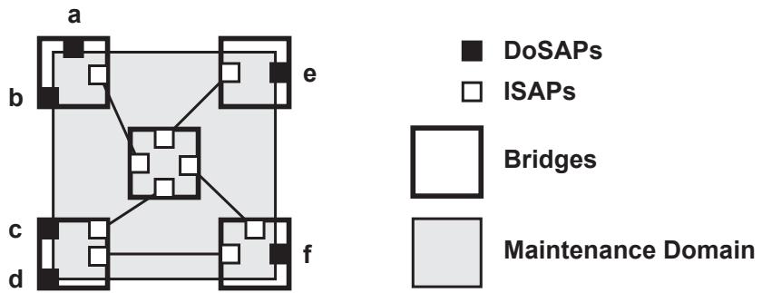
Figure 18-1—One Maintenance Domain: operator’s view
Each Maintenance Domain can be separately administered. Each Maintenance Domain is assigned a Maintenance Domain Name. This should be chosen to be unique among all those used or available to an operator, and to facilitate easy identification of administrative responsibility for the Maintenance Domain. CFM PDU formats support the creation of Maintenance Domain Names that are unique over the domain for which CFM is to protect against accidental concatenation of service instances. Ideally, these names are globally unique.
There are a number of methods to fulfill the requirements to both maintain connectivity within, and control access to, a Maintenance Domain. A Maintenance Domain can be, for example:
a) An MST Region, identified and kept separate from other Maintenance Domains, by its MST Configuration Name (8.9.2, 13.8);
b) A number of such MST Regions (13.5.3), interconnected via the CIST (13.5.2), and kept separate from other Maintenance Domains by configuring the managed objects controlling the CIST topology; or
c) An entire Virtual Bridged Network, and kept separate from other Maintenance Domains by means not specified in this standard.
d) A subset of the DoSAPs of a VLAN Bridged Network, assigned to the use of a particular higherlevel provider among many.
e) A subset of the DoSAPs of the concatenated network in item c).
f) A single physical link between two providers or between a provider and a customer.
g) A single VLAN on a single physical link between two providers or between a provider and a customer.
18.2 Service instances and MAs
When a network administrator configures a service instance for a customer, the network administrator configures some number of the DoSAPs to be accessible by that customer, assigning whatever identifiers the systems require to segregate that service instance from others supported by that Maintenance Domain (e.g., VIDs), as well as configuring other service properties (such as bandwidth profiles) for the DoSAPs. Creation of a service instance establishes a connectionless connectivity (IEEE Std 802.1AC) among the selected DoSAPs.
Configuring a MEP at each of the DoSAPs of a service instance creates an MA to monitor that connectionless connectivity. The MA is identified by a Short MA Name that is unique within the Maintenance Domain. Together, the Maintenance Domain Name and the Short MA Name form the Maintenance Association Identifier (MAID) that is carried in CFM PDUs to identify inadvertent connections among MEPs. A small integer, the MA Endpoint Identifier (MEPID) uniquely identifies each MEP among those configured on a single MA.
NOTE 1—In order to accommodate the requirements of service providers as expressed in ITU-T Y.1731 (02/2008), the Maintenance Domain Name can be configured to be null, in which case the Short MA Name needs to be globally unique, in order to provide complete protection against the accidental concatenation of service instances. Suitable choices for globally unique Short MA Names are defined in ITU-T Y.1731.
Figure 18-2 illustrates a single service instance created from the Maintenance Domain of Figure 18-1, again from the point of view of an operator. It offers four DoSAPs to a customer (C1). Each DoSAP is marked with its MEPID.
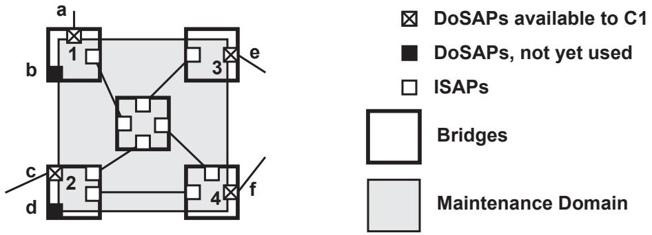
Figure 18-2—One service instance: operator’s view
Figure 18-3 illustrates that same service instance from the point of view of customer C1. The customer has four items of customer equipment attached to the four DoSAPs 1–4. The means by which the operator connects the four DoSAPs to create the service instance are invisible to the customer.
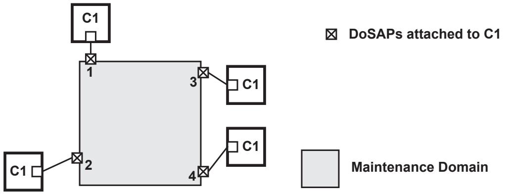
Figure 18-3—One service instance: customer’s view
NOTE 2—The term “service instance” has been used to mean an “end-to-end service supplied to a customer.” One cannot predict whether an apparently end-to-end service instance will be used by a customer to create another service instance at a still higher level to yet another customer. Therefore, no specific term is provided by this standard to label an “end-to-end” service instance.
The CFM protocol state machines and variables (see Clause 20) are used by MEPs to conduct protocol exchanges within a Maintenance Domain. Each MIP functions symmetrically with respect to the SAPs of its containing MA and service instance, and is modeled as comprising two MIP Half Functions (MHFs). Figure 18-4 specifies the symbols used for MEPs, MHFs, and MIPs in this standard, e.g., in Figure 18-7.
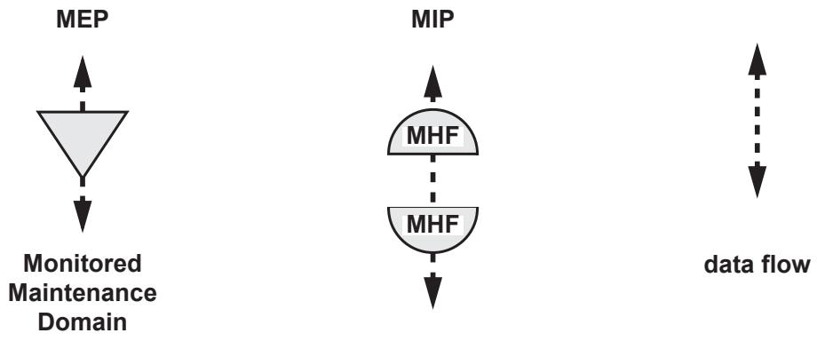
Figure 18-4—MEP and MIP Symbols
18.3 Maintenance Domain Levels
A Maintenance Domain can provide service instances to an enclosing Maintenance Domain or utilize service instances provided by an enclosed Maintenance Domain. An explicit Maintenance Domain Level (MD Level) is included in CFM PDUs to indicate the nesting relationships among Maintenance Domains, because systems can be organized into Maintenance Domains as administrative needs dictate, without necessarily adding headers to data frames to enforce a layered organization.
As part of the nested decomposition facility provided by Maintenance Domains, the CFM protocols hide information. The components of a given Maintenance Domain interior to the DoSAPs presented to the enclosing Maintenance Domain are invisible, through the CFM protocols and managed objects, to the Maintenance Domains enclosing that given Maintenance Domain, except for configured points of visibility. No part of a Maintenance Domain lower than (nested within) a given Maintenance Domain is unintentionally visible to any higher Maintenance Domain. No part of a Maintenance Domain is ever visible to any Maintenance Domain except its immediately higher (enclosing) Maintenance Domain. This enables the separation of responsibility for network administration. The administrator of an end-to-end service on the largest scale can be insulated from the administration of the networks comprising that service, and so on, in principle, down to the administration of individual LANs. This prevents, for example, a customer from learning the internal topology of an operator’s network.
In order to facilitate the diagnosis of connectivity failures, an administrator can make a DoSAP visible as an ISAP to the immediately enclosing Maintenance Domain by configuring it as a MIP. The diagnostic functions provided by CFM detect connectivity failures between any pair of MEPs in an MA. The MIPs allow these failures to be isolated to smaller segments of the network; loss of connectivity between a pair of MIPs corresponds to a MEP connectivity failure at a lower MD Level. In the lowest Maintenance Domains, the MIPs can be configured on individual Bridge Ports.
Figure 18-5 illustrates the nesting of Maintenance Domains, service instances, and MAs. It illustrates nested service instances, each configured with one MA in a Maintenance Domain. There are seven Maintenance Domains, and hence seven service instances illustrated. At the (white) “provider” MD Level, the service instance is offered to a single “customer” C1. That customer creates a (gray) service instance of his own, configured with an MA that verifies the integrity of the service instance offered by the provider. Several levels of nested Maintenance Domains are shown:
a) Covering the widest physical extent, a Maintenance Domain (and MA and service instance) at the customer MD Level has a MEP in each of four devices labeled C1 in Figure 18-5. The four DoSAPs a, b, g, and h can be configured as MIPs for this MA.
b) Covering the physical range corresponding to the limits of the end-to-end provider’s network are the MEPs a, b, g, and h belonging to the provider MD Level. The four DoSAPs c, d, e, and f can be configured as MIPs for this MA.
c) Each of the two operator networks has a Maintenance Domain at the operator MD Level. These DoSAPs are marked a through h. The unlabeled SAPs in both operators’ Maintenance Domains can be configured as MIPs for their respective MAs.
d) Three “physical” layer Maintenance Domains are shown as well. (Two are labeled “PMDL,” for “physical MD Level.”) Note that not all physical links are given Maintenance Domains.
1) A network of devices is being used, in some unspecified fashion, to offer the operators’ Bridges an emulated shared-medium LAN with four DoSAPs. A Maintenance Domain has been created to verify the connectivity of that LAN.
NOTE—This central emulated LAN could equally be a network of Bridges that are separated via nonstandard configuration from the operator clouds on either side, a network of PBBs, a network of Ethernet over SONET circuits with a central interconnect device, or an ATM Emulated LAN.25
2) Physical-level Maintenance Domains have been created at the edge of the network (on the left side) to monitor two LANs, perhaps because they include Repeaters or are otherwise unreliable.
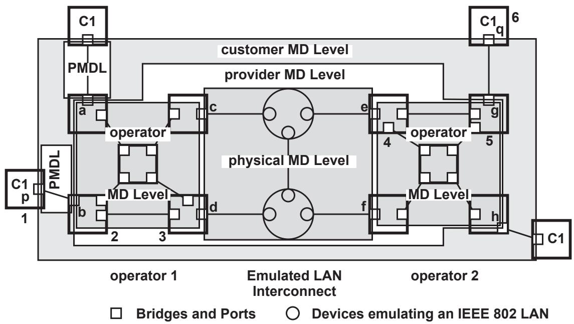
Figure 18-5—MAs: one service instance in a provider network
Figure 18-6 expands the upper right corner of Figure 18-5, including Bridges 4 and 5 and device 6. Examining device 6 (C1), readers can see that the highest MA, at the “customer” MD Level, requires a MEP in its Port q. The side of the DoSAP of this service instance that offers access to the service instance faces the center of device 6, just like the service offered by a LAN. On the other hand, in Port g, there are two service instances, each with a MEP: the white service instance at the provider MD Level, and the gray service instance at the operator MD Level. Neither of these service instances include the wire attached to Port g. Thus, ensuring the proper operation of the LAN connecting Port q to Port g is the responsibility of the MA at the customer MD Level, and not the other MAs. Port e has two MEPs, one facing in each direction.
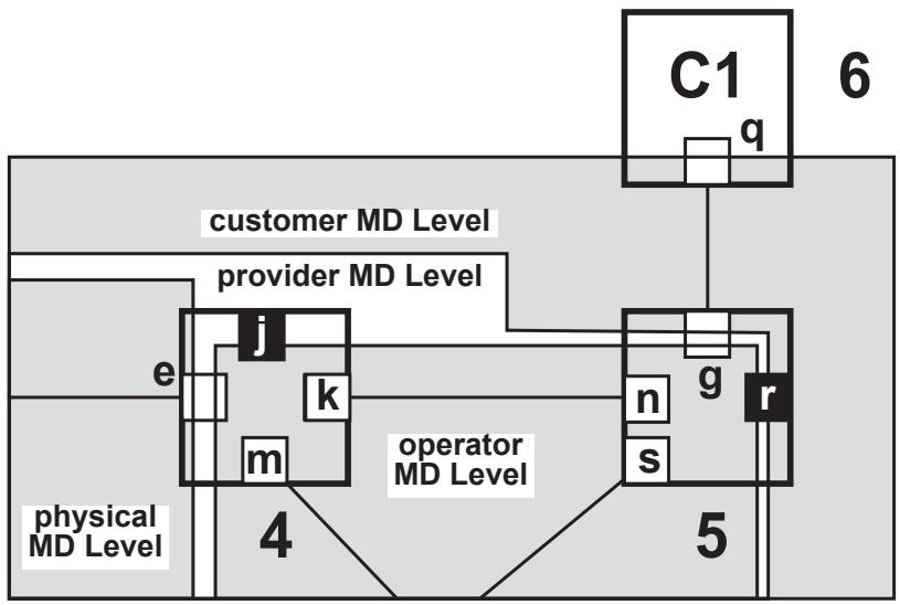
Figure 18-6—MAs: Expansion of Figure 18-5
Port g in Figure 18-6 also is an example of the fact that only the MD Level distinguishes the provider and operator Level Maintenance Domains at Port g. The single service instance in the example network shown in Figure 18-5 and Figure 18-6 is carried on a single VLAN with a single VID through the right-hand operator’s Maintenance Domain. Within that Maintenance Domain, it cannot be distinguished whether a data frame on that VID belongs to the operator, provider, or customer Maintenance Domain; it belongs to all of them. However, the MD Level permits CFM PDUs to be associated with different Maintenance Domains even when they share the same VID.
Port j and Port r have been added to Figure 18-6; they are not present in Figure 18-5. Both represent DoSAPs that have not been configured to support either a service instance or an MA. For the integrity of the network to be ensured by CFM, these DoSAPs should be configured to be Disabled.
Ports k, m, n, and s can be configured as ISAPs for the gray service instance, providing a MIP at the operator MD Level. Port e can be configured with a MIP for the provider MD Level, and Port g with a MIP for the customer MD Level.
Figure 18-7 illustrates the use of MD Levels to allow the use of CFM by a user of connectivity provided by two bridged Maintenance Domains and by the operators of each of those Maintenance Domains. It illustrates a vertical slice through Figure 18-5, including two of the customer’s devices, and the path through the network connecting them. One can see from Figure 18-7 why MD Levels are required to identify CFM PDUs; there would otherwise be no way for Bridge Port b, for example, to tell whether a given CFM PDU is to be sunk (MD Levels 2 or 3) or passed (MD Level 5).
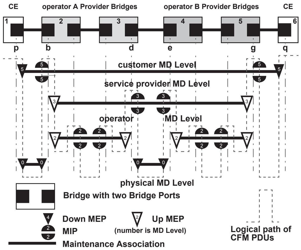
Figure 18-7—MEPs, MIPs, and MD Levels
Assignment of numerical MD Levels to the “customer” role, the “service provider” role, or the “operator” MD Levels is somewhat arbitrary, since those terms imply business relationships that cannot be standardized. See J.3 for a more detailed discussion of the assignment of MD Levels.
19 CFM entity operation
This clause specifies:
a) How the MPs that instantiate a CFM MA attach to ISS-SAPs or EISS-SAPs (19.1);
b) How MPs are addressed in networks (19.4); and
c) The architecture of MEPs (19.2), MIPs (19.3), MHFs (19.3), Linktrace Output Multiplexers (LOMs, 19.5), and Linktrace Responders (19.6), including their identification, addressing, and decomposition into components that provide the CFM functions.
NOTE—Clause 18 introduces the principles of CFM operation and the network architectural concepts that support it. Clause 20 specifies the protocols operated by the components of each MP, and Clause 21 specifies the PDU formats used by those protocols. The use of CFM within systems and networks is further described in Clause 22.
The models of operation in this clause provide a basis for specifying the externally observable behavior of MEPs and MIPs, and are not intended to place additional constraints on implementations; these can adopt any internal model of operation compatible with the externally observable behavior specified. Conformance of equipment to this standard is purely in respect of observable protocol.
19.1 Maintenance Points
The primary CFM protocol shims are called Maintenance Points (MPs). (See 19.6 for the other CFM protocol shim.) An MP can be either a MEP or an MHF. (See also 19.5 for a third type of CFM shim.) A MEP or an MHF each have two principle SAPs, an Active SAP, through which CFM PDUs produced and consumed by the MP are exchanged, and a Passive SAP, through which data frames and unprocessed CFM PDUs pass. Figure 19-1 illustrates the principle SAPs, and the symbols used for MEPs, MIPs, and MHFs in other figures, e.g., Figure 22-1. Note that an MP can be a Down MP or an Up MP, depending on whether the Passive SAP is above or below the Active SAP, respectively, in a shim diagram.
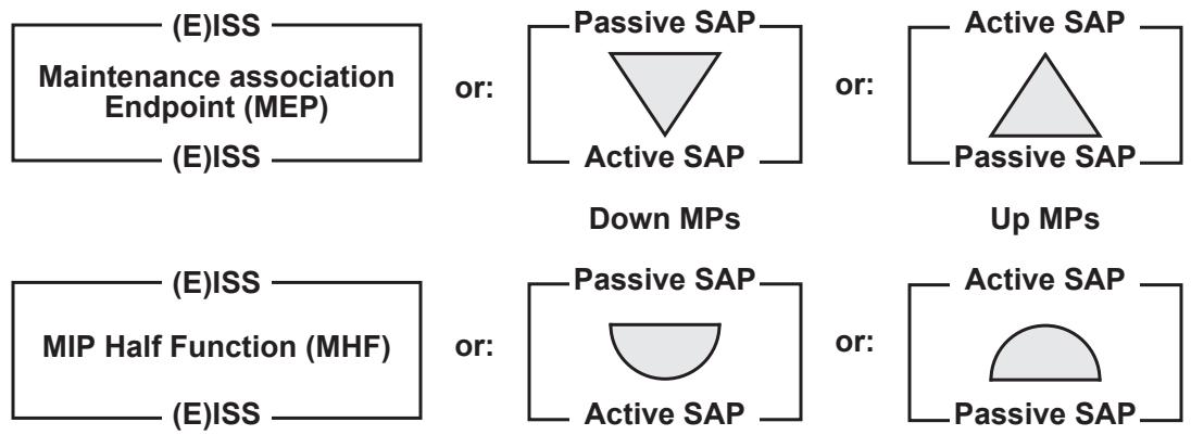
Figure 19-1—CFM Protocol shims
NOTE—The difference between Up MPs and Down MPs is explained more fully in 19.2.3 and 22.1.1.
19.2 MA Endpoints (MEPs)
A MEP can be created in either a Bridge Port (22.2) or an end station attachment to a LAN.
19.2.1 MEP identification
A MEP is associated with exactly one MA. It is identified for management purposes by two parameters, although other, additional parameters are used to manage the MEP:
a) The MAID, identifying the MA; and
b) A MEPID specific to this MEP.
The MEP is identified for data forwarding purposes by
c) A set of VIDs, including a Primary VID, inherited from the MA; or
d) An I-SID in the case of a Backbone Service Instance MA; or
e) A set of 3-tuples <ESP-DA, ESP-SA, ESP-VID> inherited from the MA when the MA is associated with a TESI; or
f) A SEG-ID inherited from the MA when the MA is associated with an Infrastructure Segment.
From the MA, the MEP inherits a Maintenance Domain, and from this it inherits:
g) A Maintenance Domain Level (MD Level), inherited from its Maintenance Domain; and
h) One of the following inherited from its MA:
1) A Primary VID; or
2) an I-SID in the case of a backbone service instance; or
3) a TE-SID in the case of a TESI; or
4) a SEG-ID in the case of an Infrastructure Segment.
A MEP is associated with two Bridge Ports. For a Down MEP, both associations are with the same Bridge Port. For an Up MEP, the two associations can be with either the same, or with different, Bridge Ports (see 19.4, J.6). The two Bridge Ports are
i) The Bridge Port on which the MEP is configured; and
j) The Bridge Port on which the MEP is implemented, and from which it inherits its individual MAC address.
The set of MEPs configured with identical values for MAID define an MA. Thus, one can say that the MA, and not the MEPs, possesses this parameter. However, an MA is a diffuse entity that can be spread among a number of geographically separated Bridges. Each Bridge has its own Maintenance Association managed object for an MA, from which its MEP’s MAID, MD Level, and Primary VID, I-SID, series of <ESP-DA, ESP-SA, ESP-VID> 3-tuples, or SEG-ID are derived. In the case of a VLAN-associated MA, the selection of which of the MA’s VIDs is the Primary VID can be overridden for a specific MEP. Although this information can be incorrectly configured (i.e., configured differently than some other Bridge), the Maintenance Association managed object ensures the uniform configuration of MEPs in a single Bridge.
Each individual MEP is configured with a MEPID that is unique within that MA. Again, the Maintenance Association managed object helps to maintain uniqueness, as it ties together the configuration parameters of the MEPs in a single Bridge and the same MA and ensures the uniqueness of the MEPIDs, at least in that Bridge.
The MAID can take a number of forms (see 21.6.5.1), including a Domain Name-based string. To prevent incorrect operation in the face of unanticipated connections among systems, the MAID is unique over the domain for which CFM is to provide such protection. If the MAID is globally unique, then that domain is global. CFM can detect connectivity errors only over a set of MEPs in which MAIDs are unique.
The MEPID is an integer in the range 1–8191. It provides each MEP with the unique identity required for the MEPs to verify the correct connectivity of the MA.
NOTE—The range of the MEPID has been chosen to be large enough to accommodate most network needs, but small enough to be used as an index into a table of remote MEPs, and not require a table lookup, in a MEP Continuity Check Receiver (19.2.8) implemented in hardware.
19.2.2 MEP functions
The MEP
a) Periodically transmits CCMs according to the managed objects defined in item e) in 12.14.6.1.3;
b) Validates received CFM PDUs as specified in 20.1, 20.2, 20.3, and 20.51;
c) Discards those CFM PDUs at a lower MD Level to that configured in the MEP (20.7.1);
d) Transmits LBMs and receives LBRs as defined in 20.2, according to the managed objects defined in 12.14.7.3;
e) Transmits LTMs, and transmits and receives LTRs as defined in 20.3, according to the managed objects defined in 12.14.7.4;
f) Responds to LBMs with LBRs as defined in 20.2.2;
g) Responds to LTMs with LTRs as defined in 20.3.2;
h) Maintains the MEP CCM Database as defined in 20.1.3;
i) May maintain the MIP CCM Database as defined in 20.1.3;
j) Maintains the variables in 20.9;
k) May decapsulate and transmit the payload of received Send Frame Messages (SFMs) (29.2.6);
l) May pass the received Reflected Frame Messages (RFMs) to RFM-Receiver (29.2.4).
Although defined as having either ISS or EISS interfaces, a MEP is highly constrained in its use of the EISS. Specifically:
m) Every frame passing through the MEP, in either direction, is emitted with its vlan_identifier and drop_eligible parameters unchanged from the value received.
n) All PDUs generated by the MEP, namely CCMs, LBMs, LBRs, LTMs, and LTRs, use the MEP’s configured Primary VID as the vlan_identifier parameter.
19.2.3 MEP architecture
Figure 19-2 illustrates the component entities of a MEP. Entities that simply pass, redirect, or filter frames without altering them, and which have no internal state, are shown with dashed outlines; those that generate or transform frames, or that have an internal state, are shown with continuous outlines. State machines describing the latter entities are specified in Clause 20. Figure 19-2 shows that the two enclosing SAPs are not equivalent. The upper SAP in the figure is the Passive SAP. It lies closer to the DoSAP of the monitored service instance. The lower SAP in the figure is the Active SAP, the one that faces the monitored service instance. Thus, Figure 19-2 illustrates one of the Down MEPs shown in Figure 22-1. To illustrate one of the Up MEPs of Figure 22-1, Figure 19-2 would have to be inverted. Note also in the diagram that there are two paths, one of which is present only in the Up MEP, and one of which is present only in the Down MEP.
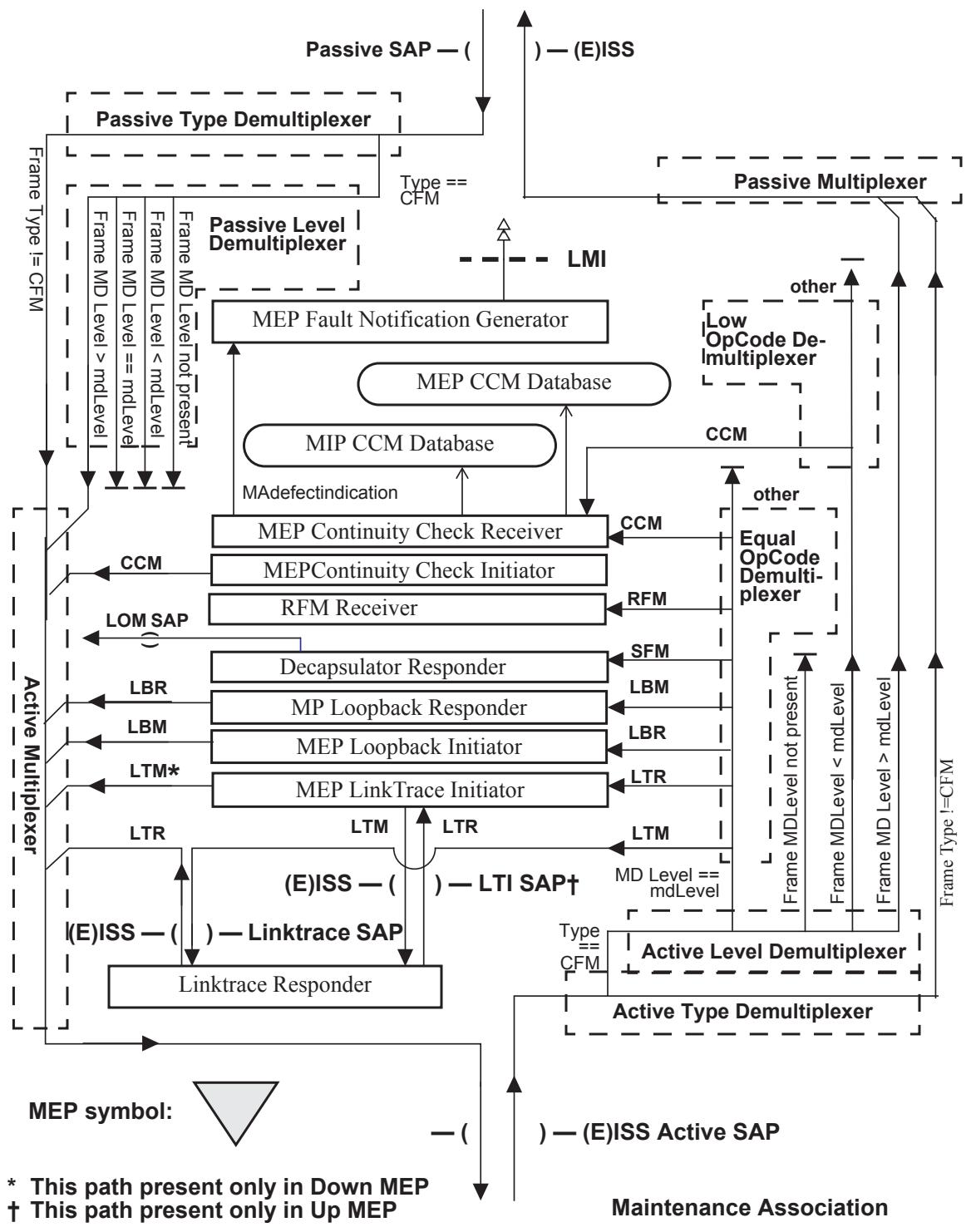
Figure 19-2—MA Endpoint (MEP)
19.2.4 MP Type Demultiplexer
There are two MP Type Demultiplexers in a MEP, the Active and the Passive Type Demultiplexers, and one in an MHF. All have the same purpose: to separate the data frames from those carrying CFM PDUs using the CFM encapsulation (21.2), output non-CFM frames to one output, and output the CFM frames to a second output. Frames containing CFM PDUs are sent to the Level Demultiplexer, and non-CFM frames are passed through the MEP intact.
NOTE—The model used for functional entities in this standard assumes that the operations of the components shown in Figure 19-2 and Figure 19-3 are atomic with respect to each other, so that the demultiplexing and multiplexing of frames, e.g., of CFM and non-CFM frames, cannot change the order of delivery of these frames. Although such reordering has no adverse consequences on this standard, and although it would not normally violate the frame ordering requirements of 6.5.3 (because CFM and non-CFM frames would seldom have the same source and destination MAC address pairs), this reordering could cause the Packet Loss Measurement operations of ITU-T Y.1731 (02/2008) to fail to operate correctly. IEEE Std 802.1AX also can disrupt the operation of ITU-T Y.1731 Packet Loss Measurement operations.
19.2.5 MP Multiplexer
There are two MP Multiplexers in a MEP or in an MHF, the Active and the Passive Multiplexers. An MP Multiplexer merges frames from multiple inputs and outputs them to a single output. No frame queuing is specified or implied by this standard.
19.2.6 MP Level Demultiplexer
There are two MP Level Demultiplexers in a MEP, the Active and Passive Level Demultiplexers. Both separate CFM PDUs according to the MD Level contained within the PDU, and the MD Level configured in the MEP, and output them to different outputs. Specifically:
a) Any CFM PDU received that is too short to contain an MD Level header field shall be discarded.
b) Otherwise, the MD Level header field of the CFM PDU is compared to the MD Level configured for the MP [item b) in 12.14.5.1.3, item b) in 12.14.3.2.2, 20.7.1], and the CFM PDU is directed to one of the three outputs of the MP Level Demultiplexer, according to whether the CFM PDU’s MD Level is less than, equal to, or greater than the MP’s MD Level.
19.2.7 MP OpCode Demultiplexer
There are two MP OpCode Demultiplexers in a MEP, the Equal and the Low OpCode Demultiplexers, and one in an MHF. Each MP OpCode Demultiplexer separates CFM PDUs that carry different values in their OpCode fields (see 21.4.3), and either discards them or passes them to the appropriate state machine. Those PDUs that do not match any of the OpCodes recognized by an MP OpCode Demultiplexer, or that are too short to contain an OpCode, are discarded by either of a MEP’s MP OpCode Demultiplexers, and passed to the Passive MHF Multiplexer by an MHF’s MP OpCode Demultiplexer. Those PDUs that do match a recognized OpCode are stored in a variable and cause another Boolean variable to be set, according to Table 19-1. These variables, in turn, trigger state machine actions. The three MP OpCode Demultiplexers separate different sets of OpCodes; see Figure 19-2 and Figure 19-3.
Table 19-1—Actions taken by MP OpCode Demultiplexers
<table><tr><td>OpCode</td><td>MEP Equal OpCode Demultiplexer</td><td>MEP Low OpCode Demultiplexer</td><td>MHF OpCode Demultiplexer</td></tr><tr><td>CCM</td><td>Sets CCMreceivedEqual and CCMequalPDU for 20.18</td><td>Sets CCMreceivedLow and CCMlowPDU for 20.18</td><td>Sets MHFrecvdCCM and MHFCCMPDU for 20.15 and transfers CCM to Passive MHF Multiplexer</td></tr><tr><td>LBM</td><td>Sets LBMreceived and LBMPDU for 20.29</td><td>Discards PDU</td><td>Sets LBMreceived and LBMPDU for 20.29 and in non-PBB-TE MHFs transfers LBM to Passive MHF Multiplexer</td></tr><tr><td>LBR</td><td>Sets LBRreceived and LBRPDU for 20.34</td><td>Discards PDU</td><td>Transfers LBR to Passive MHF Multi-plexer</td></tr><tr><td>LTM</td><td>Transfers LTM to MEP Linktrace SAP</td><td>Discards PDU</td><td>Transfers LTM to MHF Linktrace SAP</td></tr><tr><td>LTR</td><td>Sets LTRreceived and LTRPDU for 20.45</td><td>Discards PDU</td><td>Transfers LTR to Passive MHF Multi-plexer</td></tr><tr><td>Other</td><td>Discards PDU</td><td>Discards PDU</td><td>Transfers PDU to Passive MHF Multi-plexer</td></tr><tr><td>SFM</td><td>Sets SFMreceived (29.3.8.5) and SFMPDU (29.3.8.3)</td><td>Discards PDU</td><td>Sets SFMreceived (29.3.8.5) and SFMPDU (29.3.8.3). Transfers the SFM to Passive MHF Multiplexer</td></tr><tr><td>RFM</td><td>Sets RFMreceived (29.3.6.1) and RFMPDU (29.3.6.2)</td><td>Discards PDU</td><td>Sets RFMreceived (29.3.6.1) and RFMPDU (29.3.6.2). Transfers the RFM to Passive MHF Multiplexer</td></tr></table>
19.2.8 MEP Continuity Check Receiver
The MEP Continuity Check Receiver receives CCMs whose MD Levels are equal to or less than the MD Level of the MEP. The MEP Continuity Check Receiver processes those at or lower than its own MD Level, to update the MEP CCM Database. The MEP Continuity Check Receiver maintains one instance of the Remote MEP state machine (20.20) for each active remote MEP configured for this MA. In addition, the MEP Continuity Check Receiver maintains a single instance each of the Remote MEP Error state machine (20.22) and the MEP Cross Connect state machine (20.24).
If a MEP’s Continuity Check Receiver state machine’s allRMEPsDead variable (20.9.4) is set, and if the MEP is not associated with any VID or I-SID and is a Down MEP (i.e., in position 5 in Figure 22-9), then the MAC_Operational parameter presented to the Passive SAP by the MEP is false, whatever the state of the MAC_Operational parameter received from the Active SAP. Thus, a completely failed MA causes the attached Bridge Port to appear as a failed link.
Optionally, the MEP Continuity Check Receiver may maintain the MIP CCM Database as described in 19.3.10.
Various error conditions, including the receipt of CCMs at a lower MD Level than that of the MEP, cause the Remote MEP state machine to detect a defect that can in turn generate a Fault Alarm.
19.2.9 MEP Continuity Check Initiator
The Continuity Check Initiator transmits CCMs at the MD Level of the MEP only. The state machine for the Continuity Check Initiator is described in 20.12.
19.2.10 MP Loopback Responder
The Loopback Responder receives LBMs at the MD Level of the MP only, validates and filters them according to destination_address (19.4) and the PBB-TE MIP TLV (21.7.5) in the case of a PBB-TE MA and transmits LBRs in response. The state machine for the MP Loopback Responder is described in 20.29.
19.2.11 MEP Loopback Initiator
The Loopback Initiator transmits LBMs at the MD Level of the MEP only, and validates, filters according to destination_address (19.4), and counts the LBRs returned by other MPs’ Loopback Responders. The state machine for the Loopback Initiator is described in 20.32.
19.2.12 MEP Linktrace Initiator
The Linktrace Initiator transmits LTMs at the MD Level of the MEP only, and validates, filters according to destination_address (19.4), and catalogs the LTRs returned by other Bridges’ Linktrace Responders. The state machine for the Linktrace Initiator is described in 20.45. In an Up MEP the Linktrace Initiator transmits its LTMs to the Bridge’s Linktrace Responder. In a Down MEP, the Linktrace Initiator transmits its LTMs through the MEP’s own Active Multiplexer toward the MEP’s Active SAP.
19.2.13 MEP LTI SAP
An Up MEP, but not a Down MEP, has a MEP LTI SAP, an instance of the ISS or EISS. This SAP is used to
a) Transmit LTMs originated by the MEP’s Linktrace Initiator; and
b) Receive LTRs from the Linktrace Responder.
19.2.14 MEP Linktrace SAP
Every MEP has a MEP Linktrace SAP, an instance of the ISS or EISS. This SAP is used to relay received LTMs to the Linktrace Responder.
NOTE—Both the MEP LTI SAP and MEP Linktrace SAP are required so that the MEP knows, when an LTR is returned to it by the Linktrace Responder, whether the LTR is a response to an LTM generated by the MEP and thus to direct it to the MEP Linktrace Initiator, or whether the LTR is a response to an LTM previously received by the MEP and thus to forward it out the Active SAP.
19.2.15 MEP CCM Database
The MEP CCM Database is maintained by the Remote MEP state machines (20.20), one entry for each of the other MEPs configured in the MA. In addition to the Remote MEP variables (20.19) used by the Remote MEP state machine, each entry holds information obtained from the remote MEP’s CCMs as listed in 12.14.7.6.3. See also 20.1.3.
19.2.16 MEP Fault Notification Generator
The Fault Notification Generator uses the MAdefectIndication variable (see 20.9.3) in order to generate a Fault Alarm to the administrator of the Maintenance Domain to which the MA is attached. This can be accomplished by sending an SNMP Notification. The state machine for the Fault Notification Generator is described in 20.37.
19.2.17 MEP Decapsulator Responder (DR)
The MEP DR is an optional component entity within an MEP shim required only by DDCFM. Its position relative to other MP component entities is shown in Figure 19-2. When the destination_address of the SFM matches with the MEP’s MAC address, the MEP DR (29.2.6) will decapsulate the SFM, change the source_address field of the decapsulated data frame if it is required, and send the frame to the LOM SAP of selected port(s) (29.3.9.1).
19.2.18 MEP RFM Receiver
The MEP RFM Receiver is an optional component entity within a MEP shim required only by DDCFM. It is placed next to the OpCode Demultiplexer functions receiving RFM frames. When the destination_address of the RFM matches with the MP’s MAC address, the MEP RFM Receiver will pass the received RFM to the corresponding, nonstandardized RFM Analyzer.
19.3 MIP Half Function
A MIP consists of two MIP Half Functions (MHFs) on a single Bridge Port, an Up MHF and a Down MHF. (See J.6 for a more detailed explanation.) An MHF may maintain a MIP CCM Database, separate from the MEP CCM Databases.
19.3.1 MHF identification
Every MHF is characterized by one configuration parameter for management purpose, and all of the MHFs of a MIP have identical values for that configuration parameter:
a) The Maintenance Domain to which the MHF is assigned.
For data flow purposes, the MHF is characterized by
b) A Maintenance Domain Level (MD Level), inherited from its Maintenance Domain or from the Default MD Level managed object; and
c) A set of Primary VIDs, one from each MA associated with the MHF’s Maintenance Domain; or a set of I-SIDs, one for each MA associated with the MHF’s Maintenance Domain.
NOTE—When multiple VIDs are used for a single service instance, an MHF is aware of each MA’s VID set and Primary VID. Unlike the MEP, however, the MHF has no occasion to use a MAID, so is not identified by a MAID.
An MHF is associated with two Bridge Ports. For a Down MHF, both associations are with the same Bridge Port; for an Up MHF, the two associations can be with either the same, or with different, Bridge Ports (see 19.4, J.6). The two Bridge Ports are
d) The Bridge Port on which the MHF is configured; and
e) The Bridge Port on which the MHF is implemented and from which it inherits its individual MAC address.
19.3.2 MHF functions
Each MHF
a) Validates received LTMs as specified in 20.1, 20.2, 20.3, and 20.51;
b) Optionally, validates received CCMs and builds the MIP CCM Database;
c) Responds to LBMs with LBRs as defined in 20.2.2;
d) Responds to LTMs by forwarding them and responding with LTRs as defined in 20.3.2;
e) May decapsulate and transmit the payload of the received SFM (29.4.3);
f) May pass the received RFM (29.4.2).
Although defined as having either ISS or EISS interfaces, an MHF is highly constrained in its use of the EISS. Specifically,
g) Every frame passing through the MHF, in either direction, is emitted with its vlan_identifier and drop_eligible parameters unchanged from the value received.
h) All LBMs forwarded by the MHF carry the same vlan_identifier and drop_eligible parameters as the received LBM.
i) All PDUs generated by the MHF, namely LBRs, and LTRs, are transmitted with a vlan_identifier equal to the Primary VID of the MA to which the vlan_identifier of the received LBM or LTM belongs, or to the Reverse VID field of the PBB-TE MIP TLV if the received LBM or LTM carries such a TLV.
19.3.3 MHF architecture
Figure 19-3 illustrates a single MHF. Entities that simply pass, redirect, or filter frames without altering them, and which have no internal state, are shown with dashed outlines; those that generate or transform frames, or that have an internal state, are shown with continuous outlines. State machines describing the latter entities are specified in Clause 20. Figure 19-3 shows that the two enclosing SAPs are not equivalent. The upper SAP in the figure is the Passive SAP. This lies nearer an ISAP for the monitored service instance. The lower SAP in the figure is the Active SAP, the one through which CFM PDUs are actively transmitted and received. Thus, Figure 19-3 illustrates one of the Down MHFs shown in Figure 22-1. To illustrate one of the Up MHFs of Figure 22-1, Figure 19-3 would have to be inverted.
19.3.4 MHF Level Demultiplexer
The MHF Level Demultiplexer is identical to the MP Level Demultiplexer described in 19.2.6.
19.3.5 MHF Type Demultiplexer
The MHF Type Demultiplexer is identical to the MP Type Demultiplexer described in 19.2.4.
19.3.6 MHF OpCode Demultiplexer
An example of the MP OpCode Demultiplexer described in 19.2.7. The MHF OpCode Demultiplexer is fully described in that subclause.
NOTE—As indicated by the split arrows labeled “CCM” and “LBM” in Figure 19-3, some of the frames output from the MHF OpCode Demultiplexer are supplied to two other entities, and not just one.
19.3.7 MHF Multiplexer
The MHF Multiplexer is identical to the MP Multiplexer described in 19.2.5. There are two MHF Multiplexers in an MHF, the Active MHF Multiplexer and the Passive MHF Multiplexer.
19.3.8 MHF Loopback Responder
The MHF Loopback Responder is identical to the MP Loopback Responder described in 19.2.10.
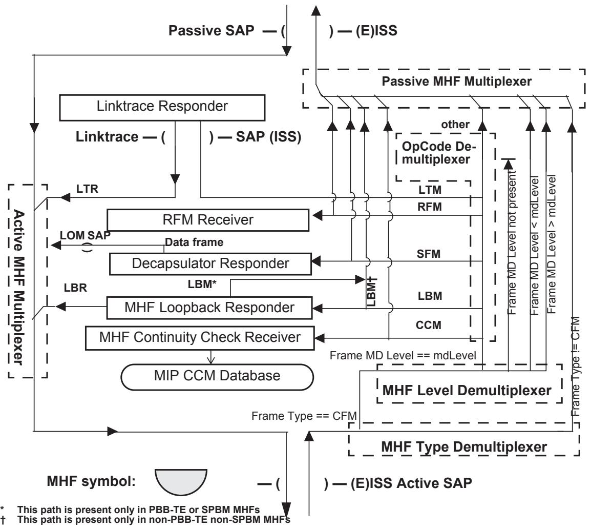
Figure 19-3—MIP Half Function (MHF)
19.3.9 MHF Continuity Check Receiver
The optional MHF Continuity Check Receiver receives CCMs, validates them, filters them by destination_address parameter (19.4), and contributes to the MIP CCM Database. From Figure 19-3, readers can see that all CCMs at the same MD Level as the MHF are presented to the MHF Continuity Check Receiver. No other information in the received CCMs is examined. In particular, the MAID in the CCM is not compared to the MHF’s MAID.
The MHF Continuity Check Receiver, and the MIP CCM Database it maintains, are not required for conformance to this standard.
19.3.10 MIP CCM Database
The MIP CCM Database is optionally maintained by an MHF or MEP. It is a list of every distinct {FID, source_address, Port number} triple from all of the CCMs presented to all of the Bridge’s MPs’ Continuity Check Receivers since the Bridge was last reset. Entries in the MIP CCM Database are timed out very slowly, on the order of one day, so that their information is available for fault isolation long after the information is no longer used for frame forwarding.
19.3.11 MHF Linktrace SAP
Every MHF has an MHF Linktrace SAP, an instance of the ISS or EISS. This SAP is used to relay received LTMs to the Linktrace Responder, and to pass LTRs from Linktrace Responder to the MHF’s Active SAP.
19.3.12 MHF DR
The MHF DR is identical to the MEP DR described in 19.2.17.
19.3.13 MHF RFM Receiver
The MHF RFM Receiver is identical to the MEP RFM Receiver described in 19.2.18.
19.4 MP addressing
The CFM entities within an MP use the Group addresses for CCM and LTM PDUs listed in Table 8-15 and Table 8-16 and in the case of PBB-TE, SPBM, and ECMP path MAs, the individual MAC addresses or the group MAC addresses that are associated with the monitored services (20.1, 20.2, 20.3). In addition, they recognize and in the case of PBB-TE, SPBM, and ECMP path MEPs use the individual MAC address of the port on which the MP is operating. This is the port on which the MP is configured, if the Bridge created the MP using the Individual MP address model (J.6.1), and is a CFM Port, if the Bridge created the MP using the Shared MP address model (J.6.2). CFM entities associated with a TESI may also use the ESP-SA parameter in the tuple identifying the corresponding ESP.
A Down MP shall not be assigned an individual MAC address [item i) in 12.14.7.1.3] that is the same as the individual MAC address configured for an MP on any other Bridge Port, because if two Bridge Ports are connected to the same LAN, but have the same MAC address, then both would respond to an LBM sent to that MAC address. The CFM protocol is specifically designed to allow an Up MP to be assigned an individual MAC address [item i) in 12.14.7.1.3] that is the same as the individual MAC address configured for an Up MP on some other Bridge Port, because it is impossible to tell, from outside the Bridge, from which Up MP a given CFM PDU was actually transmitted, or to which physical entity a given CFM PDU was delivered. See J.6 for a discussion of the assignment of individual MAC addresses to MPs.
All of the CFM entities within one MP use the same CCM and LTM addresses, and individual MAC address. The various multiplexing and demultiplexing entities pay no attention to the destination_address parameter of a received CFM PDU. Only the entities responsible for processing received CFM PDUs check a received frame’s destination_address parameter. Each of these entities recognizes frames whose destination_address parameters match the individual MAC address of the MP or are a group address. Each of these entities (except the MEP Continuity Check Receiver) filters and does not process frames whose destination_address parameters are not a group address and do not match the individual MAC address of the MP.
NOTE—Even though in the original version of IEEE Std 802.1ag-2007, the MEP Continuity Check Initiator could only transmit multicast CCMs, the MEP Continuity Check Receiver recognized unicast CCMs. In general the definitions of the various CFM receiving entities were more liberal in recognizing certain Individual or group MAC addresses than the corresponding definitions of the CFM transmitting entities a property that allows for the PBB-TE enhancements of CFM, and for improved compatibility with ITU-T Y.1731 (02/2008).
19.5 Linktrace Output Multiplexer (LOM)
The third type of CFM protocol shim is the LOM. An LOM has two principle SAPs, an Active SAP, through which CFM PDUs are transmitted, and a Passive SAP, through which pass data frames and unprocessed CFM PDUs. Figure 19-4 illustrates these SAPs and the symbol used for the LOM in other figures, e.g., Figure 22-1. An LOM can be only a Down LOM; its Passive SAP is always above the Active SAP in a shim diagram.
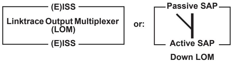
Figure 19-4—LOM shim
As illustrated in Figure 19-5, the LOM has only a single active entity, the LOM Multiplexer. It injects LTMs from the Linktrace Responder among the frames passing from the LOM’s Passive SAP to its Active SAP. Frames received from the LOM’s Linktrace SAP are transmitted through only the Active SAP, and not through the Passive SAP. All frames received on either the Active or Passive SAP are passed through the LOM unchanged, and only to the Passive or Active SAP, respectively.
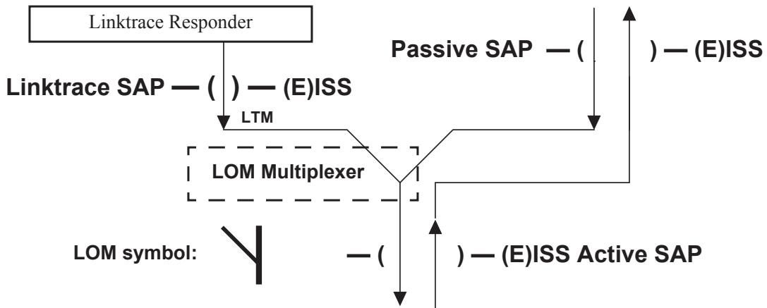
Figure 19-5—LOM architecture
NOTE 1—An LOM is not an MP, but an entity that assists the Linktrace Responder (19.6), also not an MP.
NOTE 2—The LOM exists on every Bridge Port in order to allow the Linktrace Responder to transmit an LTM on a particular Bridge Port without the possibility of that LTM being reflected back toward the Bridge’s Forwarding process. However, the LOM has no constituent entity that differentiates CFM frames from any other frames.
19.6 Linktrace Responder
A single Linktrace Responder serves all of the MHFs and MEPs in a Bridge. It is connected to every MP and LOM in the Bridge, via the Linktrace SAPs and LTI SAPs in those MPs and LOMs.
NOTE—A Linktrace Responder is not an MP, but an entity that assists the MPs (MEP and MHF, 19.2 and 19.3) in performing their functions.
In order to minimize the possibility of generating an unbounded number of responses to an LTM, an LTM is always transmitted from a Bridge on a single Bridge Port (20.3). If the LLC entity of a Bridge Port (see Figure 22-1) were used to transmit an LTM on a particular Bridge Port, the Bridge Port connectivity entity (8.5.1) would direct the LTM to the LAN, but it would also pass that frame up toward the Frame filtering entity (8.6.3), as it does for BPDUs. BPDUs are never transmitted to other Bridge Ports, however, because the Frame filtering entity filters them, based on their destination MAC addresses. The placement of MHFs at different MD Levels on different Bridge Ports, all for the same VID, precludes filtering LTMs in this manner. Therefore, the Linktrace Responder filters incoming LTMs by the destination_address parameter (19.4), and a path is required that will direct an LTM only down the Bridge Port, toward the LAN, and not toward the Frame filtering entity.
This path is provided by the Linktrace SAPs in the MEP (Figure 19-2), the MHF (Figure 19-3), and the LOM (Figure 19-5). The Linktrace SAPs are also used to direct a received LTM to the Linktrace Responder when the LTM first encounters an MP at the appropriate MD Level.
Referring to Figure 22-1, readers can see that an LTM originated by a Down MEP Linktrace Initiator is directed out to the LAN and is thus output on a single Bridge Port, as desired. The situation is different for an LTM originated by an Up MEP. The Bridge in which an Up MEP resides is, in effect, the first hop of the Linktrace protocol. The MEP LTI SAP is required in order to provide a path through which the MEP can direct its originated LTM to the Linktrace Responder. This path can also be used by the Linktrace Responder to return the resultant LTR to the MEP Linktrace Initiator. See Figure 20-16 for a diagrammatic explanation of these paths.
Table 19-2 summarizes the SAP connections between the MPs and LOM on the one hand, and the Linktrace Responder, on the other.
Table 19-2—SAP use for LTMs and LTRs
<table><tr><td colspan="2">Entity taking action</td><td>Sends originated LTM to</td><td>Relays received LTM to</td><td>Sends to Active SAP an LTR received on</td><td>Sends to Active SAP an LTM received on</td></tr><tr><td rowspan="2">Up</td><td>MEP</td><td>MEP LTI SAP</td><td>MEP Linktrace SAP</td><td>MEP Linktrace SAP</td><td>Not applicablea</td></tr><tr><td>MHF</td><td>Not applicableb</td><td>MHF Linktrace SAP</td><td>MHF Linktrace SAP</td><td>Not applicablea</td></tr><tr><td rowspan="2">Down</td><td>MEP</td><td>Not applicablec</td><td>MEP Linktrace SAP</td><td>MEP Linktrace SAP</td><td>Not applicablea</td></tr><tr><td>MHF</td><td>Not applicableb</td><td>MHF Linktrace SAP</td><td>MHF Linktrace SAP</td><td>Not applicable</td></tr><tr><td colspan="2">LOM</td><td>Not applicableb</td><td>Not applicabled</td><td>Not applicablea</td><td>LOM Linktrace SAP</td></tr></table>
a The Linktrace Responder only forwards LTMs through an LOM.
b The MHF and LOM have no MEP Linktrace Initiator, so cannot originate LTMs.
c The Down MEP transmits the LTMs it originates through its Active SAP.
d The LOM is not an MP; it cannot detect received LTMs.
A single instance of the LTR Transmitter state machine is instantiated by the Linktrace Responder. It is described in 20.50.
20 CFM protocols
MEPs and MIPs can participate in the following CFM protocols:
a) Continuity Check protocol (20.1);
b) Loopback protocol (20.2);
c) Linktrace protocol (20.3); and
d) DDCFM protocol (29.3).
The detailed operation of these protocols by the MEP (19.2) and MHF (19.3) components introduced in Clause 19 is specified in terms of a number of state machines, and the variables and procedures associated with each machine. The state machines defined adhere to the conventions in Annex E and Figure 13-14.
This clause specifies the following:
e) Relationships among the various CFM state machines and their variables (20.4);
f) Requirements for decrementing the timer counters used by a number of CFM state machines (20.5);
g) Maintenance Domain variables (20.7) that control all MAs belonging to the Maintenance Domain;
h) MA variables (20.8) that control all MEPs and MHFs belonging to the MA;
i) MEP variables (20.9) that control the MEP’s overall operation, and either apply to the majority of state machines or facilitate communication of information between the individual MEP state machines;
j) MEP Continuity Check Initiator (19.2.9) variables (20.10), procedures (20.11), and state machine (20.12);
k) (optional) MHF Continuity Check Receiver (19.3.9) variables (20.13), procedures (20.14), and state machine (20.15);
l) MEP Continuity Check Receiver (19.2.8) variables (20.16), procedures (20.17), and state machine (20.18);
m) Remote MEP variables (20.19) and state machines (20.20) used by the MEP Continuity Check Receiver to track each active Remote MEP [item ae) in 12.14.7.1.3];
n) Remote MEP Error variables (20.21) and the Remote MEP Error state machine (20.22) used by MEP Continuity Check Receiver to track received invalid CCMs;
o) MEP Cross Connect variables (20.23) and state machine (20.24) used by the MEP Continuity Check Receiver to track received CCMs that could indicate a cross connect defect;
p) MP Loopback Responder (19.2.10) variables, (20.27), procedures (20.28), and state machine (20.29);
q) MEP Loopback Initiator (19.2.11) variables (20.30), transmit procedures (20.31) and state machine (20.32), and receive procedures (20.33) and state machine (20.34);
r) MEP Fault Notification Generator (19.2.16) variables (20.35), procedures (20.36), and state machine (20.37);
s) MEP Linktrace Initiator (19.2.12) variables (20.41) and transmit procedures (20.42), and receive variables (20.43), procedures (20.44), and state machine (20.45);
t) Linktrace Responder variables (20.46), procedures (20.47), and state machine (20.48), used by the Linktrace Responder (19.6); and
u) LTR Transmitter state machine (20.50) used only by the Linktrace Responder.
To facilitate extension of this standard while maximizing interoperability, this clause further specifies:
v) Rules for CFM PDU validation and versioning (20.51) that support specific goals for extensibility and interoperability (20.51.1);
w) Rules for the identification of incoming CFM PDUs (20.52); and
x) Rules for the use of transaction identifier and sequence number fields (20.53).
The models of operation in this clause provide a basis for specifying the externally observable behavior of MHFs and MIPs, and are not intended to place additional constraints on implementations; these can adopt any internal model of operation compatible with the externally observable behavior specified. Conformance of equipment to this standard is purely in respect of observable protocol.
NOTE—Clause 18 introduces the principles of CFM operation and the network architectural concepts that support it. Clause 19 breaks down the CFM protocol entities into their components. Clause 21 specifies the PDU formats used by the CFM protocols. The use of CFM within systems and networks is further described in Clause 22.
20.1 Continuity Check protocol
The Continuity Check protocol is performed by the MEP Continuity Check Initiator (19.2.9), the MEP Continuity Check Receiver (19.2.8) of the MEP, and optionally, in the MHF Continuity Check Receiver (19.3.9) of the MHF.
For the purposes of Fault detection and the Continuity Check protocol, readers can define an MA as “a set of MEPs, all of which are configured with the same MAID and MD Level, each of which is configured with a MEPID unique within that MAID and MD Level, and all of which are configured with the complete list of MEPIDs.” The CCM (21.6) provides a means to detect connectivity failures in an MA. Each MEP can be configured to periodically transmit a CCM. A connectivity failure is then defined as one of the following:
a) Inability of a MEP to receive three consecutive CCMs from any one of the other MEPs in its MA, indicating either a MEP failure or a network failure;
b) Reception by a MEP of a CCM with an incorrect transmission interval, indicating a configuration error;
c) Reception by a MEP of a CCM with an incorrect MEPID or MAID, indicating a configuration error or a cross connect error;
d) Reception by a MEP of a CCM with an MD Level lower than that of the MEP, indicating a configuration error or a cross connect error;
e) Reception by a MEP of a CCM containing a Port Status TLV or Interface Status TLV indicating a failed Bridge Port or aggregated port; or
f) Reception by a PBB-TE MEP implementing the Traffic field, over a period of time that is 4.75 times the CCM interval or equal to 50 ms, whichever is larger, of CCMs with Traffic fields not matching the local Traffic field declaration, indicating a mismatch on the presence or absence of Backbone Service Instance entries on the CBPs that are associated with the monitored TESI.
In order to take the fullest advantage of CFM, the operator defines “correct connectivity” as being the configuration of the MEPs. If an MA is defined for every service instance, then the Continuity Check protocol can detect 100% of all connectivity faults, cross connection errors, or misconfigurations that occur within the boundaries of the configured MAs.
The transmission rate for CCMs is configurable, to accommodate different needs for error reporting, and different capabilities of network devices. The loss of three CCMs can be detected in as little as 10.8 ms (see Table 21-16). The reception of a cross connected CCM is an instantaneous occurrence.
A MEP uses its own configured timer to detect the loss of CCMs, rather than using the transmission rate of the sender (signaled in the CCM), in order to minimize the complexity of a MEP tracking hundreds of other MEPs. The timer is reset when a valid CCM is received, and a defect declared if the timer expires. The timer value is chosen such that the loss of three consecutive CCMs from a given remote MEP triggers a defect for that remote MEP, and the timer accuracy chosen to ensure against a premature defect indication. In addition, state machines in the MEP track the receipt of CCMs from remote MEPs with unexpected information, CCMs from remote MEPs not configured in the receiving MEP, CFM PDUs from a lower MD Level, or CCMs from MEPs in another MA.
Depending on the associated MA, a CCM is carried
g) In a multicast frame, with a destination_address parameter chosen according to the transmitting MEP’s MD Level, according to Table 8-15; or,
h) In the case of a PBB-TE, SPBM, or ECMP associated MA, in a unicast or multicast frame with a destination_address identified by the monitored MA.
The CCM does not generate a response. Therefore, in an MA with n MEPs, n CCMs need to be transmitted periodically, one from each MEP. Compared to a full mesh of point-to-point messages in terms of frames carried on wires, multicast CCMs require less bandwidth than the point-to-point messages, except of course for MAs with only two MEPs. And for each MEP, only one transmission and n – 1 receptions are required, instead of n – 1 of each. In addition, even in MAs with only two MEPs, using multicast instead of unicasts for CCMs obviates the need for configuration or discovery of those MEPs’ MAC addresses.
Of more importance than frame count is the fact that making the CCM a multicast frame enables the detection of a cross connect error when MEPs from two different service instances are accidentally connected. This type of error can result from a wiring error or a misconfiguration of VID mapping parameters at the boundary between two Maintenance Domains. Were CCMs unicast to specific MAC addresses, then a merging of two service instances, e.g., the accidental concatenation of two point-to-point services into a 4-SAP LAN service, would go undetected; unicast CCMs would still be delivered properly. This scenario also points out why globally unique MAIDs are important.
NOTE—The TESI Multiplex Entity (6.19) helps PBB-TE associated MEPs to avoid this type of cross connect problem for unicast CCMs by checking the source_address to determine CCMs destined to PBB-TE MAs. Correspondingly the assignment of globally unique MAIDs is not as important for PBB-TE MAs as it is for other types of MAs but in general a globally unique MAID will provide guaranties for full coverage on all possible misconfiguration errors.
Cataloging the receipt of CCMs ensures that a MEP, say, MEP 1, knows that it is receiving them from exactly the correct set of remote MEPs; it does not ensure that the CCMs transmitted by that same MEP are being received by the remote MEPs. For example, suppose that in a 10-MEP MA, all of MEP 1’s CCMs are being lost. All of the other MEPs in the MA would know about MEP 1’s problem, because they would not be receiving 1’s CCMs. But, MEP 1 itself would be unaware of the problem. In order for the operator to decide whether an MA is working properly, every MEP in the MA would have to be inspected.
For this reason, the Remote Defect Indication (RDI), a single bit, is carried by the CCM. The absence of RDI in a CCM indicates that the transmitting MEP is receiving CCMs from all configured MEPs. In the case of MEP 1’s unidirectional connectivity, MEP 1 would receive the RDI in the CCM from each remote MEP that is not receiving MEP 1’s (or any other MEP’s) CCMs. Thus, every MEP, including the receive-only MEP 1, is aware that a problem exists. The presence of RDI enables a system administrator to inspect any single MEP belonging to an MA, and discover whether there is any MEP in the MA that is detecting a defect, as well as which particular MEPs have defects.
A sequence number should be transmitted in every CCM. The receiver may use this sequence number to detect and count CCM losses. Detection of occasional CCM losses can enable a network administrator to notice suboptimal network conditions such as overloaded links, and correct them before connectivity defects and their consequent Fault Alarms occur.
An ECMP path MA is used to test multiple paths between a pair of endpoints. This type of MA has only two MEPs, at two SPT Region boundary ports. An ECMP path MEP cycles through a set of flow hash values intended to direct the CCM frames along (and thus test) different paths to the other MEP in the MA. The path taken by CCM frames with a given flow hash depends on the current state of the network (i.e., paths are subject to rerouting triggered by topology changes). Each flow hash is used in at least three consecutive CCM frames so that a fault on a particular path will be detected and reported back via an RDI signal. To avoid false positive or false negative detections of a loss of connectivity, the rate of CCM transmission should be greater than the maximum difference in latency between any pair of paths.
20.1.1 MAC status reporting in the CCM
The CCM can carry information about the status of the port on which the transmitting MEP is configured in the Port Status TLV (21.5.4) and Interface Status TLV (21.5.5). This information is not strictly within the scope of the MA bounded by the MEPs transmitting and receiving the CCM. But, by providing port status information in an Up MEP’s CCMs, this TLV allows the detection of an error immediately outboard of the MA. This in turn supports fault isolation where a problem has arisen at the point of connection to a service instance, rather than within the equipment supporting the service instance. The Port Status TLV and Interface Status TLV are particularly useful where the boundary between the equipment used by two operators to support a service instance is a link or connection that could fail. Use of the Port Status TLV and Interface Status TLV allows monitoring to be uninterrupted from end to end, without requiring management access by both operators to a single item of interface equipment, or relying on monitoring by the user of the concatenated service. The Port Status TLV and Interface Status TLV allow errors that are immediately outboard of the MA to be distinguished easily from those properly attributed to the MA itself.
Figure 18-7 provides an example. Consider a failure of the access link that connects the customer equipment (1) directly to Port b of Provider Bridge 2. Without the Interface Status TLV, none of the MEPs at the operator or service provider MD Level would be notified of the error. The Interface Status TLV allows the failure to be signaled in CCMs transmitted by the Port b service provider and operator MD Level MEPs.
20.1.2 Defects and Fault Alarms
Defects are separated from Fault Alarms (19.2.16), as is standard practice for service providers.26 The loss of CCMs or the reception of a cross connected CCM are defects. A Fault Alarm is a Management operation (12.14.7.7), an unsolicited announcement by a Bridge. If the CFM MIB module is implemented (17.5), it is an SNMP Notification. It is issued when the MEP Fault Notification Generator state machine (20.37), or the MEP Mismatch Fault Notification Generator state machine (20.40), detects that a configured time period (default, 2.5 s) has passed with one or more defects indicated, and Fault Alarms are enabled. Each of these state machine can transmit no further Fault Alarms until it is reset by the passage of a configured time period (default, 10 s) during which no defect indication is present. The normal operator procedure upon receiving a Fault Alarm is to inspect the reporting MEP’s managed objects, diagnose the fault, correct the fault, examine the MEP’s managed objects to see whether the state machine has reset, and repeat those steps until the Fault Alarm has cleared.
A number of separate defects are maintained by a MEP, as shown in Table 20-1. The defects are ranked by priority. If a higher priority defect occurs after a lower priority defect has triggered a Fault Alarm, but before the Fault Alarm has reset, then the MEP will immediately issue another Fault Alarm. This enables the operator to reliably prioritize Fault Alarms. For example, cross connect errors are typically of greater concern in a service provider environment than loss of connectivity errors.
Only the highest priority defect is reported in the Fault Alarm. Table 20-1 shows the relationships between the variables that indicate defects, the priorities of these defects, and the enumerated value reported in the Fault Alarm for each defect. The mmdefectIndication (20.38.2) is independent from the other CFM defects and is reported independently by the operation of the MEP Mismatch Fault Notification Generator state machine (20.40).
Table 20-1—Fault Alarm defects and priorities
<table><tr><td colspan="2">Defect</td><td colspan="2">Priority</td></tr><tr><td>Variable</td><td>highestDefect(20.35.9)</td><td>highestDefectPri(20.35.8)</td><td>Importance</td></tr><tr><td>xconCCMdefect(20.23.3)</td><td>DefXconCCM</td><td>5</td><td rowspan="4">Most</td></tr><tr><td>errorCCMdefect(20.21.3)</td><td>DefErrorCCM</td><td>4</td></tr><tr><td>someRMEPCCMdefect(20.35.5)</td><td>DefRemoteCCM</td><td>3</td></tr><tr><td>someMACstatusDefect(20.35.6)</td><td>DefMACstatus</td><td>2</td></tr><tr><td>someRDIdefect(20.35.7)</td><td>DefRDICCM</td><td>1</td><td>Least</td></tr></table>
20.1.3 CCM reception
Every active MEP receives and catalogs CCMs in its MEP CCM Database. Every CCM shall be examined to be sure that its MAID matches that configured in the receiving MP. This check is optional for CCMs associated with PBB-TE MAs. A receiving MEP checks to ensure that its own MEPID does not match that in the received CCM. (This could indicate either a duplicate MEPID or a network forwarding loop.) The information in the CCM is catalogued in the MEP CCM Database, indexed by the received MEPID. The information kept in the MEP CCM Database is listed in 12.14.7.6.3.
The MIP CCM Database is optionally maintained by a MEP Continuity Check Receiver or an MHF Continuity Check Receiver. It is a list of every distinct {FID, source_address, Port number} triple from all of the CCMs presented to all of the Bridge’s Down MHFs’ MHF Continuity Check Receivers since the Bridge was last reset. (See 8.8.8 for a discussion of VIDs and FIDs.) An entry in the CCM Database is retained for at least 24 h after the last CCM with its triple is received and is removed from the MIP CCM Database after, at most, 48 h. If the resources allocated for the MIP CCM Database are not sufficient to maintain all of the entries for the required time, then the least-recently updated entries should preferentially be removed to make room for new entries. See 20.3.2 for a description of the use of the MIP CCM Database.
20.2 Loopback protocol
The Loopback protocol is used for Fault verification and isolation. To verify the connectivity between MEPs and MIPs, a MEP can be instructed by a system administrator to issue one or more LBMs. The LBM is initiated by a MEP with specified destination_address, priority, and drop_eligible parameters, the destination_address being the individual MAC address of another MP within the same MA as the transmitting MEP. In the case of PBB-TE and SPBM VID MAs, the destination_address parameter for an LBM is always a MAC address associated with the terminating CBP(s). In order to identify intermediate MHFs in PBB-TE and SPBM VID MAs, an additional TLV, the PBB-TE MIP TLV (21.7.5), is carried as the first TLV in an LBM, with the receiving MHF’s MAC address in its MIP MAC address field (21.7.5.1). The receiving MP responds to the LBM with an LBR.
The Loopback protocol is performed by the MEP Loopback Initiator (19.2.11) and the MP Loopback Responder (19.2.10), the latter residing in either a MEP or an MHF.
20.2.1 LBM transmission
LBMs are transmitted by operator command as specified in 12.14.7.3. Each LBM transmitted contains a Loopback Transaction Identifier field (21.7.3) that is incremented with each transmission. That enables the transmitting MEP to correlate the returned LBRs with the transmitted LBMs. In a PBB-TE or SPBM VID MA, a PBB-TE MIP TLV is carried by the transmitted LBM as the first TLV if the targeted MP is a MIP. The MIP MAC address field (21.7.5.1) in the TLV is set to the destination_address parameter of the appropriate managed object [item b) in 12.14.7.3.2]. The PBB-TE MIP TLV provides also the Reverse VID field [21.7.5.2, item f) in 12.14.7.3.2] to be used in the VID field by a MIP transmitted LBR, and, when the LBM is to be sent on a point-to-multipoint TESI, the Reverse MAC field (21.7.5.3) associated with MAC addresses to be used by the LBR. The LBM can carry an arbitrary amount of data to help diagnose faults that are sensitive to the amount or pattern of data in a frame [item d) in 12.14.7.3.2]. It can be sent with any priority or drop_eligible parameters [item e) in 12.14.7.3.2].
No means for specifying the rate at which the LBMs are to be sent is provided. A Bridge shall not transmit LBMs at a rate that would cause the queues serving that Bridge Port to overflow and drop LBMs, were there no other traffic being inserted into those queues.
20.2.2 LBM reception and LBR transmission
When an LBM is received by an MP Loopback Responder (19.2.10), it may be examined for validity and discarded if invalid. Regardless of whether the LBM is examined for validity, it shall be discarded if the source_address is a Group and not an individual MAC address. Also, if the destination_address does not match the MAC address of the receiving MP, and the MP Loopback Responder does not reside in a PBB-TE or SPBM VID MHF, the MP shall discard the LBM. If the receiving MP Loopback Responder resides in a non-PBB-TE and non-SPBM VID associated MHF and the destination_address is a group MAC address, the MHF shall discard the LBM. If the MP Loopback Responder state machine resides in a PBB-TE MEP and the received LBM carries a PBB-TE MIP TLV, the MEP shall discard the LBM. If the MP Loopback Responder state machine resides in an SPBM VID MEP and the received LBM carries a PBB-TE MIP TLV, the MEP may process the LBM if the MIP MAC address field matches the MEP’s address and shall otherwise discard the LBM. PBB-TE and SPBM VID MHFs forward all received LBMs and only stop and process those that carry a PBB-TE MIP TLV containing in their MIP MAC address field the MAC address of the receiving MIP [item f) in 20.28.1]. If the frame passes these tests, the receiving MP generates an LBR and transmits it to the originating MEP. Every M_UNITDATA.indication (or EM_UNITDATA.indication) parameter and octet in the mac_service_data_unit in the LBM is copied to the LBR’s M_UNITDATA.request (or EM_UNITDATA.request) with the following exceptions:
a) The source_address parameter of the received LBM is used as the destination_address parameter for the transmitted LBR. In the case of a PBB-TE MHF, this destination_address value will be overwritten by the value of the group MAC address in the Reverse MAC field of the PBB-TE MIP TLV, if this is present. In the case of a PBB-TE MEP, the destination_address parameter for the transmitted LBR is the value of the ESP-DA of the MA’s ESP that has the replying MEP’s MAC address [item i) in 12.14.7.1.3] in its ESP-SA field;
b) The source_address parameter for the LBR is the MAC address of the replying MP. If the MP is associated with a PBB-TE MHF, the source_address is set to the destination_address of the received LBM if this is an individual MAC address or otherwise to the value carried in the Reverse MAC field, contained in the PBB-TE MIP TLV;
c) If the LBM was received at a PBB-TE MHF and contains a PBB-TE MIP TLV, then the vlan_identifier in the LBR is set to the value in the Reverse VID field; otherwise, the vlan_identifier in the LBR is set to the value of the Primary VID associated with the replying MP [item d) in 12.14.7.1.3, item a) in 12.14.3.2.2, item c) in 12.14.5.3.2];
d) The OpCode field is changed from LBM to LBR; and
e) (Only in PBB-TE MAs) The vlan_identifier for the LBR is the Primary VID [item d) in 12.14.7.1.3] associated with the replying PBB-TE MEP; otherwise, if the received LBM contained a PBB-TE MIP TLV, the value in the Reverse VID field is used as the vlan_identifier parameter.
The receiver of an LBM shall not interpret any of the other fields or TLVs in the LBM. The contents of any TLVs that do not violate the validation criteria of 20.51, but are not specified in this standard, and any valid Organization-Specific TLV not known to the receiving MP, shall be ignored, and not interpreted, by the receiver, except that their contents shall be copied to the LBR.
NOTE—This standard provides no means for transmitting an LBM with a group MAC address. The MP Loopback Responder responds to LBMs sent to the CCM Group address because ITU-T Y.1731 (02/2008) provides for transmitting such messages. See J.4.
20.2.3 LBR reception
When an LBR is received by a MEP Loopback Initiator (19.2.11), it is checked to see whether the destination_address parameter matches the MAC address of the receiving MEP, and discarded if not. Next it is checked to see whether its Loopback Transaction Identifier field matches that of a recently transmitted LBM, and the appropriate counter incremented, either the in-sequence counter [item y) in 12.14.7.1.3] or the out-of-sequence counter [item z) in 12.14.7.1.3].
If the Shared MP address model for implementing CFM is used by a particular Bridge, then as mentioned in 20.52, there is an ambiguity in the identification of the particular Up MP to which an LBR is destined. Therefore, a Bridge using this model uses a single variable for managing the Loopback Transaction Identifier fields for all MPs sharing the same MAC address, MAID, and MD Level.
The receiver of an LBR may compare its contents bit-for-bit with the remembered contents of the corresponding LBM, and increment a variable [item aa) in 12.14.7.1.3] if they do not match.
20.3 Linktrace protocol
The Linktrace protocol is performed by the MEP Linktrace Initiator (19.2.12), associated with a single MEP, and the Linktrace Responder (19.6) associated with a Bridge.
A Linktrace Message (LTM) is transmitted by a MEP Linktrace Initiator in order to perform path discovery and fault isolation. The LTM carries a target MAC address. It is carried in a frame, with a destination_address taken from Table 8-16 according to the MD Level of the transmitting MEP, or the ESP-DA field of the appropriate ESP in the case of a PBB-TE MA (20.31.1), or an individual or group address in the case of an SPBM VID MA, and is relayed as such through the bridged network until it reaches an MP at the appropriate MD Level. That MP intercepts the LTM and deflects it to a Bridge’s Linktrace Responder. The Linktrace Responder determines whether its Bridge’s MAC Relay Entity would forward an ordinary data frame with the specified target MAC address and vlan_identifier to an egress Bridge Port, or would filter or flood it. If the single egress port is found, or if the receiving MP is the terminating MP, or if the MP is associated with a PBB-TE MA or an SPBM VID MA, the Linktrace Responder sends a unicast Linktrace Reply (LTR) to the originator of the LTM, whose MAC address was also carried as payload in the LTM. The LTR is sent after a random delay in the range 0 < delay 1 s, to mitigate the load on the originating MEP. In addition, if the MP through which the LTM was received was an MHF, the Linktrace Responder forwards an altered version of the LTM in the direction of the target MAC address. The MEP Linktrace Initiator that originated the initial LTM collects the LTRs. These provide sufficient information to construct the sequence of MPs that would be traversed by a data frame sent to the target MAC address.
Path discovery in a connectionless environment is more challenging than a connection-oriented environment. In Bridged Networks, it can be especially challenging, since the MAC address of the target of an LTM can be deleted from the FDB by a TCN immediately after a network topology change, and ages out and is deleted a few minutes (Max Age) after last being learned when a fault results in isolating the target from the MEP originating the LTM.
CFM offers three ways to address the problem of ageing out MAC addresses:
a) Launching the Linktrace protocol automatically, immediately following the detection of a fault, such that it gets exercised within the Max Age window;
b) Maintaining information about the destination MP at the intermediate points along the path by using the optional MIP CCM Database, 19.3.9 and 20.1.3; and
c) Maintaining normal path information by issuing periodic LTMs during normal operations.
NOTE—Periodic LTMs allow a system administrator to determine the MIPs along the paths among MEPs during normal operations, thus establishing a baseline for subsequent fault isolation. However, triggering LTMs at rates approaching the CCM transmission interval could overwhelm the Bridges’ ability to process CFM PDUs. See also 22.5.
20.3.1 LTM origination
LTMs are transmitted by a MEP Linktrace Initiator in response to an operator command (12.14.7.4). The nextLTMtransID [item b) in 12.14.7.4.3, 20.41.1] of each LTM transmitted is retained for at least 5 s after the LTM is transmitted. The LTM Transaction Identifier values transmitted by a given MEP are unique over this time period in order to match LTRs returned by slow MPs to the LTM that triggered the slow LTR. Initializing the nextLTMtransID to a random value27 and incrementing it once per LTM transmitted satisfies this criterion. For each LTM transmitted, the MEP Linktrace Initiator creates an entry in a Linktrace database (20.41.2). This entry is indexed by nextLTMtransID for retrieval when a corresponding LTR is received.
The transmitting Bridge can maintain a separate sequence of LTM Transaction Identifiers per MEP if multiple MEPs in the same service instance and at the same MD Level have different MAC addresses, but uses a common sequence of LTM Transaction Identifiers for MEPs that share both of these characteristics.
In the case of a VID-based MA, the destination_address of an LTM is the group MAC address reserved for LTMs and appropriate to the MD Level of the originating MEP according to Table 8-16. In the case of a PBB-TE MEP, the destination_address of an LTM is the entry in the ESP-DA field of the 3-tuple of the MA’s ESP that has the MEP’s MAC address in its ESP-SA field. In the case of an SPBM VID MEP, the destination_address of an LTM is the individual B-MAC address of a remote system or the SPBM group MAC address (27.15) associated with an I-SID associated with the source MEP.
The Target MAC Address field [item c) in 12.14.7.4.2, 21.8.6] in the LTM can be any individual MAC address. However, since MEPs are required to periodically transmit CCMs, a MEP’s MAC address is likely to be known to the MIPs along the path. Conversely, a MIP’s MAC address, because the MIP does not initiate any CFM PDUs, can be unknown to intermediate Bridges unless it has recently replied to an LBM or LTM.
In the case of a PBB-TE MA, a PBB-TE MIP TLV is carried by the LTM, containing the Reverse VID [21.7.5.2, item e) in 12.14.7.4.2], to be used in the VID field by a MIP transmitted LTR, and, when the LTM is to be sent on a point-to-multipoint TESI, the Reverse MAC field (21.7.5.3) associated with MAC addresses to be used by the corresponding LTRs. The MIP MAC address field (21.7.5.1) in a PBB-TE MIP TLV associated with an LTM is null.
The MEP Linktrace Initiator in a Down MEP transmits the LTM through its Active SAP, toward the LAN attached to its Bridge Port. The MEP Linktrace Initiator in an Up MEP transmits the LTM through its MEP LTI SAP to its own Bridge’s Linktrace Responder. That Linktrace Responder handles the LTM as described in 20.3.2. The Linktrace Responder can forward the LTM through the LOM Linktrace SAP and can respond through the MEP LTI SAP with an LTR. Thus, when an LTM is initiated in an Up MEP, the originating Bridge is the first hop.
20.3.2 LTM reception, forwarding, and replying
An LTM at a particular MD Level is forwarded as an ordinary data frame until it encounters a MEP at an equal or higher MD Level, or an MHF at an equal MD Level. A MEP at a higher MD Level discards the LTM without further processing. An MP at an equal MD Level directs the LTM to its Bridge’s Linktrace Responder. Since, for a given MD Level, different Bridge Ports on a given Bridge can be configured with MHFs, MEPs, both, or neither, an LTM can be both forwarded as ordinary data and processed by the Bridge’s Linktrace Responder. An LTM that is originated by an Up MEP is forwarded directly to its Bridge’s Linktrace Responder and not through the MEP’s Active SAP toward the Frame filtering process.
The Linktrace Responder is responsible for processing and forwarding LTMs, and for replying to them with LTRs. All LTMs are subject to the validation criteria of 20.51.4; invalid or incorrectly addressed LTMs are discarded without further processing. After processing the LTM, the Linktrace Responder can return an LTR through the SAP on which the LTM was received and can forward at most one altered copy of the received LTM through an LOM on a different Bridge Port. It never forwards an LTM past a MEP at the LTM’s own MD Level or higher, i.e., a MEP that bounds the LTM’s MA. An LTM carries an LTM TTL field (21.8.4) that is decremented each time the LTM passes through a Linktrace Responder. The LTM is not forwarded if this field is 0 or 1 when the LTM is received.
The Linktrace Responder replies to the LTM if
a) An ordinary data frame, with the same vlan_identifier as the LTM, a destination_address equal to the Target MAC Address field (21.8.6) of the LTM and received on the same Bridge Port as the LTM, would be forwarded through exactly one other Bridge Port (or to just the Management Port); or
b) The UseFDBonly bit of the Flags field of the LTM is 0, the Target MAC Address field (21.8.6) of the LTM is found in the Bridge’s MIP CCM Database (19.3.10), and that entry in the MIP CCM Database identifies a Bridge Port (or the Management Port), other than the one on which the LTM was received; or
c) The MAC address of the MP that received the LTM equals the Target MAC Address field of the LTM;
and
d) LTM TTL field is nonzero when the LTM is received.
The single output Port identified in the preceding item a) or item b) is called the Egress Port. The Linktrace Responder forwards a copy of the LTM through the LOM on the Egress Port, with a new source_address parameter and the LTM TTL field decremented by 1, only if all of the following conditions are met:
e) An LTR was generated for the reasons specified in the preceding item a) or item b), but not item c);
f) The LTM was received via an MHF Linktrace SAP or a MEP LTI SAP, and not a MEP Linktrace SAP;
g) The Egress Port does not have a MEP at or above the LTM’s MD Level; and
h) The received LTM TTL field was greater than 1.
The source_address parameter in the forwarded LTM does not change if the MA is associated to a TESI.
NOTE 1—When tracing the path to a known MAC address, all of the Bridges on a shared medium will receive the LTM. Making transmission of the LTR and forwarding of the LTM conditional on the FDB query ensures that at most one of those Bridges will reply. Similarly an LTM can be flooded, through a region of the network that has not yet learned the target MAC address, without provoking a storm of LTRs.
LTMs are forwarded immediately in order to minimize the time required to complete a Linktrace operation. LTRs are enqueued for delivery at a later time. If the LTM was received by a Down MEP or a Down MHF, the LTR includes a Reply Ingress TLV (21.9.8) describing that MP. If not received by a Down MEP, and if the Egress Port has an Up MEP or Up MHF configured for the LTM’s MA, the LTR includes a Reply Egress TLV (21.9.9). These TLVs report, to the originating MEP, the MIPs and/or the MEP along the path to the targeted MAC address.
If an LTM is forwarded to a shared medium LAN, and if one or more of the other Bridges attached to that LAN have only two Bridge Ports forwarding data for the LTM’s vlan_identifier (including that shared medium), and if the MAC address in the LTM’s Target MAC Address field (21.8.6) is not present in those Bridge’s FDBs (or if the targeted MAC address is present in more than one Bridge’s MIP CCM Database), then more than one of those receiving Bridges can respond to the LTM with an LTR. Also, an anomaly in the operation of Bridge or LAN, e.g., an FDB is recording its information incorrectly, can cause LTR responses along multiple paths.
The Reply TTL field in the LTR would be sufficient by itself for the originating MEP Linktrace Initiator to order the LTRs returned along a single path. The LTMs and LTRs also include three values, the Last Egress Identifier (21.9.7.1), Next Egress Identifier (21.9.7.2), and LTM Egress Identifier TLV (21.8.8), that enable the originating MEP to unambiguously construct the tree of paths taken by the LTM, if LTRs are returned along multiple paths.
NOTE 2—If an MA cannot be configured to transmit CCMs more quickly than Max Age causes MAC addresses to be removed from the Bridges’ FDBs, then the best practice for the system administrator is to trigger an LTM transmission only after triggering a few LBMs to the target MAC address. This helps to ensure that the target MAC address is known to the intermediate Bridges, so that the LBM will return a result, and so that LTRs will be returned only along a single path.
NOTE 3—If unusual conditions prompt responses along multiple paths, the delay in transmitting the LTR reduces the chance that the originating MEP’s receiving capabilities will be overwhelmed by the returned LTRs.
NOTE 4—The forwarded LTM uses, as its source address, the address of the MP through which the LTM is forwarded, not the source address of the original LTM. This means that a Bridge’s Linktrace Responder need not be fully synchronized with its Relay Entity, as the latter can change the active topology rapidly without the risk of an adjacent Bridge learning the wrong direction for the source MAC address from an LTM. However, in the case of TESIs, the forwarded LTM simply uses the source address of the original LTM since the previous considerations do not apply in a PBB-TE Region. The LTM TTL field ensures that an LTM that is being processed while the active topology is changing will not be forwarded in a persistent loop.
The MEP Linktrace Initiator ignores any TLVs received in an LTR that do not violate the validation criteria of 20.51, but are not specified in this standard, and it ignores any valid Organization-Specific TLV not known to it. Except as otherwise specified in 20.47.3 and 20.47.4, all TLVs, whether known or ignored by the Linktrace Responder, are copied from the received LTM to the forwarded LTM, and from the received LTM to the LTR.
NOTE 5—Forwarding all unknown TLVs in both the LTM and the LTR enables future revisions of this standard, and designers of Organization-Specific TLVs, to add new capabilities.
20.3.3 LTR reception
LTRs are transmitted by a Linktrace Responder in response to a received LTM and returned in a unicast frame to the MEP Linktrace Initiator that originated the LTM. The MEP Linktrace Initiator validates the received LTR, discarding it if invalid, if the destination_address parameter does not match the MAC address of the Bridge Port on which the MEP resides, or if the LTR Transaction Identifier field does not match any of those stored in the MEP’s Linktrace database (20.41.2), created when the LTM was originated.
Each validated LTR triggers the creation of a new entry in the Linktrace database, accessible as a managed object through the Read Linktrace Reply command (12.14.7.5). If no entry exists in the Linktrace database for this MEP, corresponding to the LTR Transaction Identifier field, the MEP Linktrace Initiator creates a new entry, with an index value [item c) in 12.14.7.5.2] of 1. If an entry does exist matching that field, it creates a new entry, with an index value one greater than the last matching LTR. In either case, the MEP Linktrace Initiator stores the contents of the LTR in this new entry.
See J.5 for a description of a method to reconstruct the path(s) taken by an LTM, based on the information in the Linktrace database.
20.4 CFM state machines
The relationships among a MEP’s state machines are illustrated in Figure 20-1. That figure uses conventions similar to those of 13.24 and of Figure 13-13: open arrows denote variables that are set by one state machine and both read and set by another; closed arrows denote variables that are set by the owning state machine, and only read by other state machines. Not included in Figure 20-1 are the MEP Continuity Check Initiator state machine, the MP Loopback Responder state machine used in the MEP, and all of the MHF and Linktrace Responder state machines, because they operate independently.
20.5 CFM state machine timers
The timer variables declared in this subclause are part of the specification of the operation of CFM. The accompanying descriptions of their meaning and use are provided to aid in the comprehension of the protocol only and are not part of the specification.
One instance of the following shall be implemented:
a) LTFwhile (20.5.1).
One instance of the following shall be implemented per MEP:
b) CCIwhile (20.5.2);
c) errorCCMwhile (20.5.3);
d) xconCCMwhile (20.5.4);
e) LBIwhile (20.5.5); and
f) FNGwhile (20.5.6).
One instance of the following shall be implemented per PBB-TE MEP implementing the Traffic field (21.6.1.4):
g) mmCCMwhile (20.5.7)
h) mmLocwhile (20.5.8)
i) mmFNGwhile (20.5.9)
One instance per MEP of the following shall be implemented for each remote MEP in the MEP’s MA (those MEPs in the MA other than the MEP, itself):
j) rMEPwhile (20.5.10).
The “granularity” of a timer variable is the periodicity with which it is decremented.
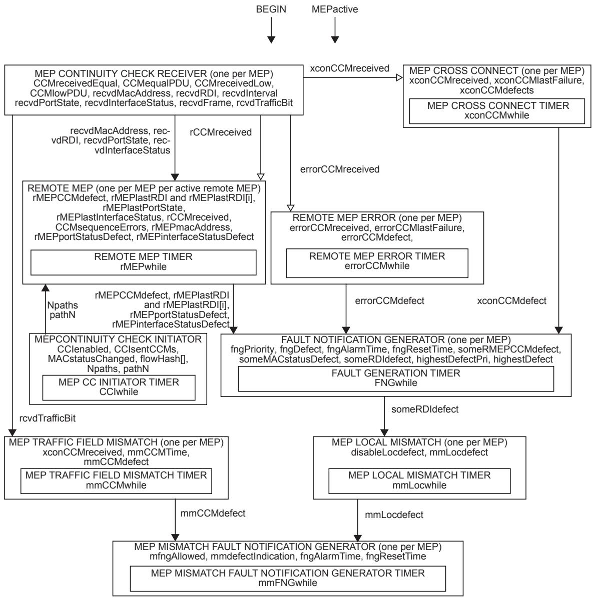
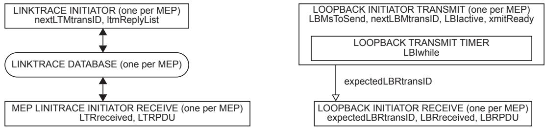
Figure 20-1—MEP state machines—overview and relationships
20.5.1 LTFwhile
A timer variable used by the LTR Transmitter state machine to time out the expected transmission of LTRs.
20.5.2 CCIwhile
Timer counter for transmitting CCMs. CCIwhile has a granularity finer than or equal to 1/4 of the time represented by the CCMinterval variable.
20.5.3 errorCCMwhile
Timer counter for timing out invalid CCMs. errorCCMwhile has a granularity finer than or equal to 1 ms.
20.5.4 xconCCMwhile
Timer counter for timing out cross connect CCMs. xconCCMwhile has a granularity finer than or equal to 1 ms.
20.5.5 LBIwhile
A timer variable used by the MEP Loopback Initiator transmit state machine to time out the expected reception of LBRs.
20.5.6 FNGwhile
A timer variable used by the MEP Fault Notification Generator state machine to wait for defects to stabilize and disappear.
20.5.7 mmCCMwhile
Timer counter for declaring mismatch defects based on the received Traffic field. mmCCMwhile has a granularity finer than or equal to 1 ms.
20.5.8 mmLocwhile
Timer counter for declaring mismatch defects based on inconsistencies in locally declared values (20.9.9). mmLocwhile has a granularity finer than or equal to 1 ms.
20.5.9 mmFNGwhile
A timer variable used by the MEP Mismatch Fault Notification Generator state machine (20.40) to wait for defects to stabilize and disappear.
20.5.10 rMEPwhile
Timer counter for timing out CCMs. rMEPwhile has a granularity finer than or equal to 1/4 of the time represented by the CCMinterval variable. A Bridge shall not set rMEPCCMdefect within (3.25 CCMtime(CCMinterval)) seconds of the receipt of a CCM, and shall set rMEPCCMdefect within (3.5 CCMtime(CCMinterval)) seconds after the receipt of the last CCM. This variable is readable as a managed object [item c) in 12.14.7.6.3].
NOTE—In order to generate a Defect upon the loss of three CCMs, but not generate a Defect when only two CCMs have been lost, a minimum resolution is required for rMEPwhile. The granularity specified for rMEPwhile, when used with the state machine in Figure 20-5, generates a Defect in a maximum of (3.5 CCMtime(CCMinterval)) seconds, and a minimum of (3.25 CCMtime(CCMinterval)) seconds.
20.6 CFM procedures
The following procedure is global to the system:
a) CCMtime() (20.6.1).
20.6.1 CCMtime()
CCMtime() takes, as a parameter, a value of the form used in the CCMinterval variable (20.8.1) and the CCM Interval field in a CCM PDU (21.6.1.3). It returns, as a value, the corresponding time interval, in the form used by the CCIwhile or rMEPwhile timer, as appropriate (20.5.2, 20.5.10).
20.7 Maintenance Domain variable
The following variable is local to a single Maintenance Domain and is accessible by more than one state machine:
a) mdLevel (20.7.1).
20.7.1 mdLevel
The integer MD Level of the Maintenance Domain. This variable is available as a managed object [item b) in 12.14.5.1.3].
20.8 MA variables
The following variable is local to a single MA and is accessible by more than one state machine:
a) CCMinterval (20.8.1).
20.8.1 CCMinterval
The configured time between CCM transmissions. The value configured for this variable shall be one of the nonzero values in Table 21-16. This variable is available as a managed object [item e) in 12.14.6.1.3].
20.9 MEP variables
The following variables are local to a single MEP and are accessible by more than one state machine:
a) MEPactive (20.9.1);
b) enableRmepDefect (20.9.2);
c) MAdefectIndication (20.9.3);
d) allRMEPsDead (20.9.4);
e) lowestAlarmPri (20.9.5);
f) presentRDI (20.9.6); and
g) MEPprimaryVID (20.9.7).
The following variables may be present only in PBB-TE MAs, are local to a single PBB-TE MEP and are accessible by more than one state machine:
h) presentTraffic (20.9.8)
i) presentmmLoc (20.9.9)
The following variables are present only in Infrastructure Segment MAs, are local to a single Infrastructure Segment MEP, and are accessible by more than one state machine:
j) ISpresentTraffic (20.9.10);
k) ISpresentmmLoc (20.9.11).
The following variable is present only in ECMP path MAs, is local to a single ECMP path MEP, and is accessible by more than one state machine:
l) EpMEP (20.9.12).
20.9.1 MEPactive
A Boolean indicating the administrative state of the MEP. True indicates that the MEP is to function normally, and false that it is to cease functioning. This variable is available as a managed object [item e) in 12.14.7.1.3].
NOTE—MEPactive controls the BEGIN input to the MEP state machines. Therefore, for any MEP that has been completely configured, it is as much an indication of the operative state of the MEP as a control over that state.
20.9.2 enableRmepDefect
A Boolean indicating whether frames on the service instance monitored by this MEP’s MA are enabled to pass through this Bridge Port by the spanning tree protocol (Clause 13) and VLAN topology management (Clause 11). Set true either if they are enabled, or if the MEP is not associated with a single value of the Port State and VID member set, else false. In a Bridge, the value of enableRmepDefect is determined from the Port State (8.4) of the spanning tree instance that controls the MEP’s Primary VID, and that VID’s member set (8.8.10), as shown in Table 20-2. This variable also controls the value output in the Port Status TLV (21.5.4).
Table 20-2—Deriving enableRmepDefect and Port Status TLV in a Bridge
<table><tr><td>Port State (8.4)</td><td>Bridge Port in Primary VID's member set</td><td>Port Status TLV (21.5.4)</td><td>enableRmepDefect</td></tr><tr><td colspan="2">Disabled, blocked, listening, broken, discardinga or learning</td><td>psBlocked</td><td>False</td></tr><tr><td rowspan="2">Forwarding</td><td>No</td><td>psBlocked</td><td>False</td></tr><tr><td>Yes</td><td>psUp</td><td>True</td></tr></table>
a “Discarding” is used in place of the values disabled, blocked, listening, or broken defined in IETF RFC 4318.
A MEP that is
a) configured in an MA that is not associated with a VID;
b) on a Bridge that is running multiple instances of the spanning tree;
c) on a Bridge Port that is not excluded by Static VLAN Registration Entries from membership in VIDs belonging to more than one spanning tree instance;
can be unable to generate an unambiguous value for the Port Status TLV, because different MSTIs can be in different Port States. For a MEP in that position, enableRmepDefect is always true.
20.9.3 MAdefectIndication
A Boolean indicating the operational state of the MEP’s MA. True indicates that at least one of the remote MEPs configured on this MEP’s MA has failed, and false indicates either that all are functioning, or that the MEP has been active for less than the time-out period. MAdefectIndication is true whenever an enabled defect is indicated. That is, MAdefectIndication is true if and only if, for one or more of the variables someRDIdefect, someRMEPCCMdefect, someMACstatusDefect, errorCCMdefect, or xconCCMdefect, that variable is true and the corresponding priority of that variable from Table 20-1 is greater than or equal to the value of the variable lowestAlarmPri.
20.9.4 allRMEPsDead
A Boolean indicating that this MEP is receiving none of the remote MEPs’ CCMs. allRMEPsDead is the logical AND of all of the rMEPCCMdefect variables.
20.9.5 lowestAlarmPri
An integer value indicating the lowest defect priority (see Table 20-1) that can trigger the generation of a Fault Alarm. This variable is a managed object [item k) in 12.14.7.1.3].
20.9.6 presentRDI
A Boolean value indicating the state of the RDI bit in CCMs transmitted by this MEP. presentRDI is true if and only if one or more of the variables someRMEPCCMdefect, someMACstatusDefect, errorCCMdefect, or xconCCMdefect is true, and if the corresponding priority of that variable, from Table 20-1, is greater than or equal to the value of the variable lowestAlarmPri.
20.9.7 MEPprimaryVID
An integer specifying a VID, one of the VIDs assigned to the MEP’s MA, which is to be used as the Primary VID for this MEP. This variable is related to the managed object item d) in 12.14.7.1.3. It is not necessarily numerically equal to that object, however. MEPprimaryVID always contains the numerical value of the Primary VID. The managed object may contain 0, to indicate that the Primary VID is that of the MEP’s MA, or contain the Primary VID itself, if the MA’s VID is overridden for this particular MEP. In the case of a MEP associated with a PBB-TE MA, this value is not directly configurable but it takes the value of the ESP-VID field in the 3-tuple of the PBB-TE MA’s ESP that has the MEP’s MAC address in its ESP-SA field.
20.9.8 presentTraffic
A Boolean value indicating if at least one backbone service instance is configured to use the TESI's ESP upon which this PBB-TE MEP is transmitting CCMs. presentTraffic is TRUE if and only if the Backbone Service Instance table, of the CBP associated with this MEP, contains an entry that has in its B-VID and Default Backbone Destination fields the values of ESP-VID and ESP-DA of the monitored TESI’s ESP which originates at the MEP.
20.9.9 presentmmLoc
presentmmLoc is the logical AND of presentRDI (20.9.6) and presentTraffic (20.9.8).
20.9.10 ISpresentTraffic
A Boolean value indicating if at least one TESI protected by the IPG is configured to use the segment monitored by the Infrastructure Segment MEP. ISpresentTraffic is TRUE if and only if the port upon which this MEP is configured is the outbound port of the entry in the FDB corresponding to the TESI protected by the IPG.
20.9.11 ISpresentmmLoc
ISpresentmmLoc is the logical AND of presentRDI (20.9.6) and ISpresentTraffic (20.9.10).
20.9.12 EpMEP
Boolean. This variable is used to condition actions related to ECMP path MEPs. It is true for ECMP path MEPs and false otherwise.
20.10 MEP Continuity Check Initiator variables
The following variables are local to the MEP Continuity Check Initiator state machine:
a) CCIenabled (20.10.1);
b) CCIsentCCMs (20.10.2);
c) MACstatusChanged (20.10.3);
d) Npaths (20.10.4);
e) flowHash[] (20.10.5);
f) pathN (20.10.6); and
g) CCMcnt (20.10.7).
20.10.1 CCIenabled
Controls the transmission of CCMs. When set to true, CCMs are transmitted. When set to false, CCM transmission ceases. This variable is available as a managed object [item g) in 12.14.7.1.3].
20.10.2 CCIsentCCMs
Integer value. CCIsentCCMs is initialized to 1 when the MEP is created and may be used thereafter by xmitCCM() to fill the Sequence Number field of a transmitted CCM. This variable is available as a managed object [item w) in 12.14.7.1.3].
20.10.3 MACstatusChanged
Boolean. MACstatusChanged triggers the transmission of one extra CCM. If the Port Status TLV (21.5.4) or Interface Status TLV (21.5.5) is being transmitted by the MEP, and if CCMinterval indicates a transmission interval of 10 s or slower, MACstatusChanged is set to true whenever the value reported in either of those two TLVs changes. MACstatusChanged is reset to false by the MEP Continuity Check Initiator state machine.
20.10.4 Npaths
Integer value. The number of paths being tested by this MEP. The value is 1 (default) except in the case of ECMP path MEPs that may test a set of paths by using one destination address and different flow hash values.
20.10.5 flowHash[ ]
This variable is applicable only for ECMP path MEPs.
Array of 16-bit values. A set of flow hash values used to test a set of paths to a given destination address. The default is a single NULL value.
20.10.6 pathN
This variable is applicable only for ECMP path MEPs.
Integer value in the range 0..(Npaths-1) and all arithmetic using this variable is modulo Npaths. The index of the current path (flow hash) being used in CCMs sent from the MEP. This value is shared with the Remote MEP state machine to enable correlation of received RDIs with the cycle of paths being tested.
20.10.7 CCMcnt
This variable is applicable only for ECMP path MEPs.
Integer value in the range 0..3 and all arithmetic using this variable is modulo 4. This variable is a counter used to send each flowHash[] value in four successive CCMs.
20.11 MEP Continuity Check Initiator procedures
The following procedure is local to the MEP Continuity Check Initiator state machine:
a) xmitCCM() (20.11.1).
20.11.1 xmitCCM()
xmitCCM() constructs and transmits a CCM on the Active SAP using an M_UNITDATA.request as follows:
a) Sets the destination_address parameter to the value from Table 8-15 corresponding to the MEP’s MD Level. In the case of a PBB-TE associated MEP, SPBM path MEP, or ECMP path MEP, the destination_address parameter is set to the MAC address indicated by the ESP-DA field of the ESP having in its ESP-SA field the MAC address of the MEP. In the case of an SPBM VID MEP (27.18.1), the destination_address parameter is set to the SPBM group MAC address (27.15) associated with the source MEP and the SPBM default I-SID. In the case of an SPBM group MEP, the destination_address parameter is set to the SPBM group MAC address (27.15) assigned to the source MEP’s CBP for the SPBM group MA’s I-SID;
b) Sets the source_address parameter to the MAC address of the MEP [item i) in 12.14.7.1.3];
c) Sets the priority parameter according to the MEP’s managed objects [item h) in 12.14.7.1.3];
d) Sets the drop_eligible parameter to false;
e) In the case of ECMP with flow filtering, the time_to_live and flow_hash parameters must be set. The time_to_live parameter is set to the TTL Value in the Flow Filtering Control Table entry on the CBP for the source MEP’s VID [item d) in 12.16.5.5.2]. In the case of an SPBM VID MEP or SPBM group MEP, the flow_hash parameter is set to zero. In the case of an ECMP path MEP, the flow_hash parameter is set to the value of flowHash[pathN];
f) Places the MEP’s MD Level (20.7.1) in the MD Level field (21.4.1);
g) Fills the CCM Interval field (21.6.1.3) with the CCM transmission interval (20.8.1, item e) in 12.14.6.1.3);
h) Fills the RDI field (21.6.1.1) with the presentRDI variable (20.9.6);
i) Should copy CCIsentCCMs (20.10.2) to the Sequence Number field of the CCM (21.6.3), else copies 0 into that field;
j) Places the MEP’s MAID into the appropriate fields of the CCM [item a) in 12.14.1.2.2, item b) in 12.14.5.3.2, and 21.6.5.1 through 21.6.5.6];
k) Places the MEP’s MEPID [item g) in 12.14.6.1.3] into the Maintenance association Endpoint Identifier field (21.6.4);
l) As controlled by the managed objects item e) in 12.14.3.1.3, item d) in 12.14.5.1.3, and item d) in 12.14.6.1.3, places a Sender ID TLV (21.5.3) in the CCM, identifying the transmitting system;
m) Optionally, places a Port Status TLV (21.5.4) in the CCM, reporting the status of the Bridge Port;
n) Optionally, places an Interface Status TLV (21.5.5) in the CCM, reporting the status of the Bridge Port;
o) Increments CCIsentCCMs by 1, wrapping around from $2 ^ { 3 2 } - 1$ to 0;
p) Only in the case of a PBB-TE MEP, optionally fills the Traffic field (21.6.1.4) with the presentTraffic variable (20.9.8); and
q) Only in the case of an Infrastructure Segment MEP, optionally fills the Traffic field (21.6.1.4) with the value ISpresentTraffic (20.9.10).
20.12 MEP Continuity Check Initiator state machine
Each MEP Continuity Check Initiator (19.2.9) instantiates one MEP Continuity Check Initiator state machine. The MEP Continuity Check Initiator state machine implements the function specified by the state diagram in Figure 20-2, the variable declarations in 20.10 and the procedures in 20.11.
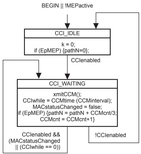
Figure 20-2—MEP Continuity Check Initiator state machine
NOTE—Figure 20-2 indicates that the setting of MACstatusChanged causes CCIwhile to be reset and thus changes the phase of the CCM transmission cycle. An alternative formulation of state machine could transmit an extra CCM, but not reset CCIwhile. Whether setting MACstatusChanged in a MEP causes CCIwhile to be reset is not specified by this standard.
20.13 MHF Continuity Check Receiver variables
The following variables are defined for the MHF Continuity Check Receiver:
a) MHFrecvdCCM (20.13.1); and
b) MHFCCMPDU (20.13.2).
20.13.1 MHFrecvdCCM
A Boolean value set to true by the MHF OpCode Demultiplexer (19.3.6) when a CCM at the MHF’s MD Level is received. Cleared by the MHF Continuity Check Receiver state machine.
20.13.2 MHFCCMPDU
Structure. Loaded with the M_UNITDATA.indication or EM_UNITDATA.indication parameters of the CCM PDU received by the MHF OpCode Demultiplexer (19.3.6) when a CCM at the MHF’s MD Level is received.
20.14 MHF Continuity Check Receiver procedures
The following procedure is defined for the MHF Continuity Check Receiver:
a) MHFprocessCCM() (20.14.1).
20.14.1 MHFprocessCCM()
MHFprocessCCM() shall validate the received CCM according to 20.51.4 and discard the received CCM if invalid. Otherwise, MHFprocessCCM() records the FID, source_address, and Port number of the received CCM in the MHF’s MIP CCM Database.
20.15 MHF Continuity Check Receiver state machine
The MHF Continuity Check Receiver state machine implements the functions specified by the state diagram in Figure 20-3, using the variables in 20.13 and procedures in 20.14.
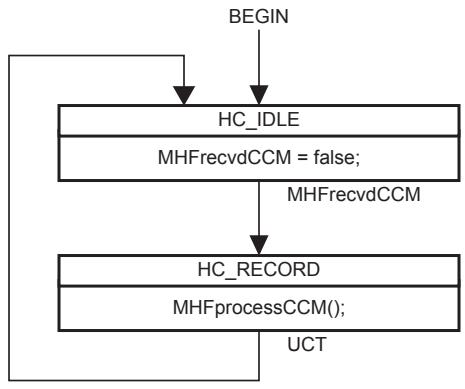
Figure 20-3—MHF Continuity Check Receiver state machine
20.16 MEP Continuity Check Receiver variables
The following variables are defined for the MEP Continuity Check Receiver:
a) CCMreceivedEqual (20.16.1);
b) CCMequalPDU (20.16.2);
c) CCMreceivedLow (20.16.3);
d) CCMlowPDU (20.16.4);
e) recvdMacAddress (20.16.5);
f) recvdRDI (20.16.6);
g) recvdInterval (20.16.7);
h) recvdPortState (20.16.8);
i) recvdInterfaceStatus (20.16.9);
j) recvdSenderId (20.16.10);
k) recvdFrame (20.16.11); and
l) CCMsequenceErrors (20.16.12).
The following variable is present only in PBB-TE MEP or Infrastructure Segment MEP that supports the Traffic field (21.6.1.4), is local to a single PBB-TE MEP or Infrastructure Segment MEP, and is accessible by the MEP Mismatch state machines (20.26):
m) rcvdTrafficBit (20.16.13)
20.16.1 CCMreceivedEqual
Boolean flag. Set by the MEP Equal OpCode Demultiplexer (19.2.7) when a CCM at the MEP’s MD Level is received. Cleared by the MEP Continuity Check Receiver state machine.
20.16.2 CCMequalPDU
Structure. Loaded with the M_UNITDATA.indication or EM_UNITDATA.indication parameters of the CCM PDU received by the MEP Equal OpCode Demultiplexer (19.2.7) when a CCM at the MEP’s MD Level is received.
20.16.3 CCMreceivedLow
Boolean flag. Set by the MEP Low OpCode Demultiplexer (19.2.7) when a CCM below the MEP’s MD Level is received. Cleared by the MEP Continuity Check Receiver state machine.
20.16.4 CCMlowPDU
Structure. Loaded with the M_UNITDATA.indication or EM_UNITDATA.indication parameters of the CCM PDU received by the MEP Low OpCode Demultiplexer (19.2.7) when a CCM below the MEP’s MD Level is received.
20.16.5 recvdMacAddress
Set by the MEPprocessEqualCCM() procedure with the source_address from the last-received CCM from the remote MEP served by this copy of the Remote MEP state machine.
20.16.6 recvdRDI
Boolean flag. Set by MEPprocessEqualCCM() according to the RDI field of the last-received valid CCM.
20.16.7 recvdInterval
Timer counter indicating timer counter equivalent of the value encoded in the CCM Interval field of a received CCM. Set by MEPprocessEqualCCM().
20.16.8 recvdPortState
(optional) Enumerated variable indicating the contents of the Port Status TLV (21.5.4) of the last-received valid CCM or psNoPortStateTLV: Indicates either that no CCM has been received or that no Port Status TLV was present in the last CCM received. Set by MEPprocessEqualCCM().
20.16.9 recvdInterfaceStatus
(optional) Enumerated variable indicating the contents of the Interface Status TLV (21.5.5) of the lastreceived valid CCM or isNoInterfaceStatusTLV: Indicates either that no CCM has been received or that no Interface Status TLV was present in the last CCM received. Set by MEPprocessEqualCCM().
20.16.10 recvdSenderId
(optional) Enumerated variable indicating the contents of the Sender ID TLV (21.5.3) of the last-received valid CCM or isNoSenderIdTLV: Indicates either that no CCM has been received or that no Sender ID TLV was present in the last CCM received. Set by MEPprocessEqualCCM().
20.16.11 recvdFrame
Octet string holding a frame received by MEPprocessEqualCCM(). recvdFrame can be reconstructed either from the M_UNITDATA.indication information presented to the MEP through the Active SAP, or from the EM_UNITDATA.indication presented to the EISS Multiplex Entity. The size of recvdFrame indicates the size of the reconstructed frame. When set to the value NULL, the size of recvdFrame is 0.
20.16.12 CCMsequenceErrors
The total number of out-of-sequence CCMs received from all remote MEPs. This variable is readable as a managed object [item v) in 12.14.7.1.3].
20.16.13 rcvdTrafficBit
Boolean flag which is applicable only for PBB-TE MEPs and Infratructure Segment MEPs supporting the Traffic field (21.6.1.4). Set by MEPprocessEqualCCM() according to the Traffic field of the last-received valid CCM.
20.17 MEP Continuity Check Receiver procedures
The following procedures are defined for the Continuity Check Receiver:
a) MEPprocessEqualCCM() (20.17.1); and
b) MEPprocessLowCCM() (20.17.2).
20.17.1 MEPprocessEqualCCM()
Called by the MEP Continuity Check Receiver state machine whenever a CCM is received at the MD Level of the MEP. MEPprocessEqualCCM() processes the CCM contained in CCMequalPDU as follows:
a) MEPprocessEqualCCM() shall process the CCM according to 20.51.4.2, and may validate the CCM according to 20.51.4.3, and discard any frames that fail the validation.
b) Otherwise, if the MAID of the received CCM does not exactly match the MAID configured in the receiving MEP [item a) in 12.14.1.2.2, item b) in 12.14.5.3.2], then MEPprocessEqualCCM() sets xconCCMreceived (20.23.1) true (this procedural step being optional in the case of a PBB-TE MEP
or Infrastructure Segment MEP, SPBM path MEP, or ECMP path MEP), reconstructs the frame containing the CCM into recvdFrame, and places a timer counter value into recvdInterval corresponding to the value of the CCM Interval field in the received CCM.
c) Otherwise, if
1) MEPID in the received CCM is not configured in the receiving MEP [item g) in 12.14.6.1.3]; or
2) MEPID in the received CCM matches the MEPID of the receiving MEP [item b) in 12.14.6.3.2]; or
CCM Interval field in the received CCM does not match that configured for the receiving MEP [item e) in 12.14.6.1.3];
then MEPprocessEqualCCM() sets errorCCMreceived (20.21.1) true, reconstructs the frame containing the CCM into recvdFrame, and places a timer counter value into recvdInterval corresponding to the value of the CCM Interval field in the received CCM.
d) Otherwise, MEPprocessEqualCCM()
1) Copies the source_address parameter into recvdMacAddress;
2) Copies the RDI field to recvdRDI;
3) Optionally copies the Port Status TLV to recvdPortState;
4) Optionally copies the Interface Status TLV to recvdInterfaceStatus;
5) Optionally copies the Sender ID TLV to recvdSenderId;
6) Optionally updates the Bridge’s MIP CCM Database; and
7) Sets the rCCMreceived variable (20.19.6) for the particular instance of the Remote MEP state machine corresponding to the Maintenance association Endpoint Identifier field in the CCM.
8) Only in the case of a PBB-TE MEP or Infrastructure Segment MEP, optionally copies the Traffic field (21.6.1.4) to rcvdTrafficBit (20.16.13).
MEPprocessEqualCCM() should also
e) Compare the Sequence Number field in the received CCM to the value saved in the MEP CCM Database;
f) If both values are not 0, and if the new value is not 1 greater than the last, increment CCMsequenceErrors (20.16.12); and
g) Store the received Sequence Number in the MEP CCM Database.
20.17.2 MEPprocessLowCCM()
Called by the MEP Continuity Check Receiver state machine whenever a CCM is received with an MD Level that is less than the MEP’s MD Level (mdLevel, 20.7.1). MEPprocessLowCCM() processes the CCM contained in CCMlowPDU as follows:
a) MEPprocessLowCCM() shall process the CCM according to 20.51.4.2, and may validate the CCM according to 20.51.4.3, and discard any frames that fail the validation.
b) Otherwise, MEPprocessLowCCM() sets xconCCMreceived (20.23.1) true, reconstructs the frame containing the CCM into recvdFrame, and places a timer counter value into recvdInterval corresponding to the value of the CCM Interval field in the received CCM.
20.18 MEP Continuity Check Receiver state machine
The MEP Continuity Check Receiver state machine implements the functions specified by the state diagram in Figure 20-4, using the variables in 20.16 and procedures in 20.17.
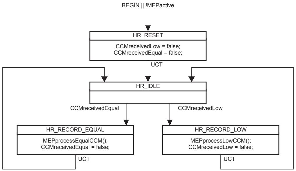
Figure 20-4—MEP Continuity Check Receiver state machine
20.19 Remote MEP variables
The following variables are local to the Remote MEP state machine:
a) rMEPCCMdefect (20.19.1);
b) rMEPlastRDI and rMEPlastRDI[i] (20.19.2);
c) rMEPlastPortState (20.19.3);
d) rMEPlastInterfaceStatus (20.19.4);
e) rMEPlastSenderId (20.19.5);
f) rCCMreceived (20.19.6);
g) rMEPmacAddress (20.19.7);
h) rMEPportStatusDefect (20.19.8);
i) rMEPinterfaceStatusDefect (20.19.9); and
j) lastPathN (20.19.10).
20.19.1 rMEPCCMdefect
Reports the state of the remote MEP. When true, no CCM has been received from the remote MEP for at least (3.25 CCMtime(CCMinterval)) seconds.
20.19.2 rMEPlastRDI and rMEPlastRDI[i]
Boolean flag. Contains the RDI flag from the last-received CCM. This variable is readable as a managed object [item e) in 12.14.7.6.3]. In the case of an ECMP path MEP, if Npaths > 1, there is a set of variables rMEPlastRDI[i] of size Npaths (20.10.4). In this case the variable rMEPlastRDI is the logical OR of the members of the set rMEPlastRDI[i]. Each member of the set rMEPlastRDI[i] is set if an RDI is received while pathN == i and is reset if no RDI is received while pathN == i in the last CCM cycle of the MEP Continuity Check Initiator state machine.
20.19.3 rMEPlastPortState
Enumerated value. Contains the value obtained from the Port Status TLV (21.5.4) of the last-received CCM or a value indicating that the last-received CCM contained no Port Status TLV. This variable is readable as a managed object [item f) in 12.14.7.6.3].
20.19.4 rMEPlastInterfaceStatus
Enumerated value. Contains the value obtained from the Interface Status TLV (21.5.5) of the last-received CCM or a value indicating that the last-received CCM contained no Interface Status TLV. This variable is readable as a managed object [item g) in 12.14.7.6.3].
20.19.5 rMEPlastSenderId
Enumerated value. Contains the value obtained from the Sender ID TLV (21.5.3) of the last-received CCM or a value indicating that the last-received CCM contained no Sender ID TLV. This variable is readable as a managed object [item h) in 12.14.7.6.3].
20.19.6 rCCMreceived
Boolean flag set true by MEPprocessEqualCCM() to indicate that a CCM has been received that matches the configured expectations of a particular Remote MEP state machine. Cleared to false by the Remote MEP state machine.
20.19.7 rMEPmacAddress
One field in each entry in the MEP CCM Database for a remote MEP, containing source_address of the lastreceived CCM from that remote MEP. This variable is readable as a managed object [item d) in 12.14.7.6.3].
20.19.8 rMEPportStatusDefect
A Boolean indicating that the remote MEP is reporting a failure in its Port Status TLV (21.5.4). It is true only if the last received CCM contained a Port Status TLV that contained some value other than psUp, i.e., the remote MEP’s Bridge Port is not forwarding data. It is equal to (rMEPlastPortState != psUp && rMEPlastPortState != psNoPortStateTLV: Indicates either that no CCM has been received or that no Port Status TLV was present in the last CCM received).
20.19.9 rMEPinterfaceStatusDefect
A Boolean indicating that the remote MEP is reporting a failure in its Interface Status TLV (21.5.5). It is true only if the last received CCM contained an Interface Status TLV that contained some value other than isUp, i.e., the remote MEP’s Bridge Port is not available for forwarding data. It is equal to (rMEPlastInterfaceStatus != isUp && rMEPlastInterfaceStatus != isNoInterfaceStatusTLV: Indicates either that no CCM has been received or that no Interface Status TLV was present in the last CCM received).
20.19.10 lastPathN
This variable is applicable only for ECMP path MEPs.
Integer value. The variable lastPathN holds the previous value of the pathN variable.
20.20 Remote MEP state machine
The Remote MEP state machine implements the function specified by the state diagram in Figure 20-5 and the variable declarations in 20.19, and utilizes the procedures in 20.17.
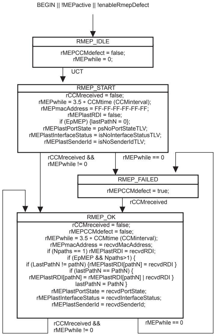
Figure 20-5—Remote MEP state machine
20.21 Remote MEP Error variables
The following variables are local to the Remote MEP Error state machine:
a) errorCCMreceived (20.21.1);
b) errorCCMlastFailure (20.21.2); and
c) errorCCMdefect (20.21.3).
20.21.1 errorCCMreceived
Boolean flag set true by MEPprocessEqualCCM() if an invalid CCM is received. Cleared to false by the Remote MEP Error state machine.
20.21.2 errorCCMlastFailure
Octet string with the same characteristics as recvdFrame. Value controlled by the Remote MEP Error state machine. Readable as a managed object [item t) in 12.14.7.1.3]. Size is sufficient to retain a frame containing a maximum-length CCM in errorCCMlastFailure.
20.21.3 errorCCMdefect
A Boolean flag set and cleared by the Remote MEP Error state machine to indicate that one or more invalid CCMs has been received, and that 3.5 times that CCM’s transmission interval has not yet expired. This variable is readable as a managed object [item r) in 12.14.7.1.3].
20.22 Remote MEP Error state machine
The Remote MEP Error state machine implements the function specified by the state diagram in Figure 20-6 and the variable declarations in 20.21.
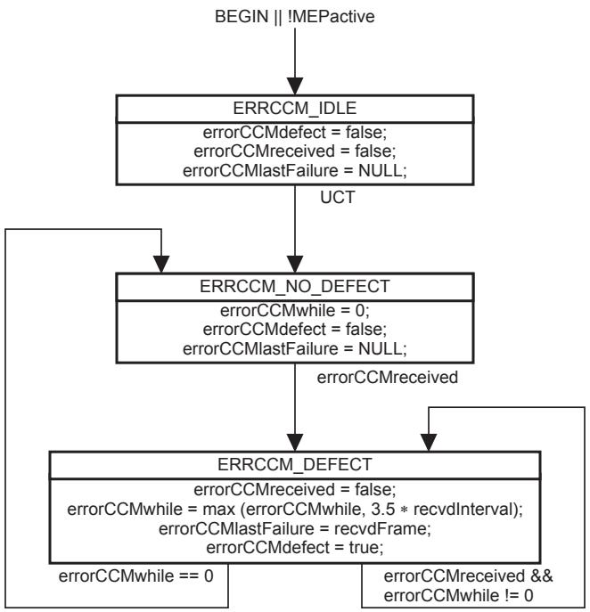
Figure 20-6—Remote MEP Error state machine
20.23 MEP Cross Connect variables
The following variables are local to the MEP Cross Connect state machine:
a) xconCCMreceived (20.23.1);
b) xconCCMlastFailure (20.23.2); and
c) xconCCMdefect (20.23.3).
20.23.1 xconCCMreceived
Boolean flag set true by MEPprocessEqualCCM() when a cross connect CCM is received. Cleared to false by the MEP Cross Connect state machine.
20.23.2 xconCCMlastFailure
Octet string with the same characteristics as recvdFrame. Value controlled by the MEP Cross Connect state machine. Readable as a managed object [item u) in 12.14.7.1.3]. Size is sufficient to retain a frame containing a maximum-length CCM.
20.23.3 xconCCMdefect
A Boolean flag set and cleared by the MEP Cross Connect state machine to indicate that one or more cross connect CCMs has been received, and that 3.5 times of at least one of those CCMs’ transmission interval has not yet expired. This variable is readable as a managed object [item s) in 12.14.7.1.3].
20.24 MEP Cross Connect state machine
The MEP Cross Connect state machine implements the function specified by the state diagram in Figure 20-7 and the variable declarations in 20.23.
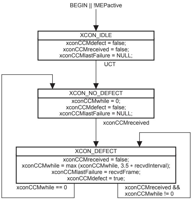
Figure 20-7—MEP Cross Connect state machine
20.25 MEP Mismatch variables
The following variables are local to the MEP Mismatch state machines for a PBB-TE MEP or Infrastructure Segment MEP implementing the Traffic field (21.6.1.4):
a) mmCCMreceived (20.25.1)
b) mmCCMdefect (20.25.2)
c) mmCCMTime (20.25.3)
d) disableLocdefect (20.25.4)
e) mmLocdefect (20.25.5)
20.25.1 mmCCMreceived
Boolean flag set to TRUE when rcvdTrafficBit (20.16.13) does not match the presentTraffic (20.9.8) in the case of a PBB-TE MEP or rcvdTrafficBit (20.16.13) does not match the ISpresentTraffic (20.9.10) in the case of an Infrastructure segment MEP.
20.25.2 mmCCMdefect
A Boolean flag set and cleared by the MEP Mismatch state machines to indicate that one or more CCMs with Traffic fields not matching the presentTraffic (20.9.8) have been received in the case of a state machine associated with a PBB-TE MEP or that one or more CCMs with ISpresentTraffic (20.9.10) has been received in the case of a state machine associated with an Infrastructure Segment MEP, over a period that is greater than 3.5 times the configured CCM transmission rate and given by the mmCCMTime (20.25.3). This variable is readable as a managed object [item ah) in 12.14.7.1.3].
20.25.3 mmCCMTime
The time used to initiate the mmCCMwhile timer. This is the time taken for a remote IB-BEB to send a CCM with the correct information in the Traffic field and is tied to the target protection switching time, i.e., 50 ms, as a mismatch would be normal prior to the completion of a protection switch. In the most generic case it is equal to the Detection Time + Restoration Procedure Time + Restoration Transfer time. This gives a time of 3.5 CCM interval + Restoration Procedure Time + 1.25 CCM interval. As a result its value is set to max (50 ms, 4.75 CCMtime (CCMinterval) + 10 ms).
20.25.4 disableLocdefect
A Boolean that disables the indication of the mmLocdefect. The variable is always set to TRUE for PBB-TE MAs that are not part of a TE protection group. On a PBB-TE MEP associated with the working entity in one or more TE protection groups to which its monitoring TESI MA is assigned, disableLocdefect is TRUE if and only if either p.SF (26.10.3.3.2) or LoP (26.10.3.3.4) is TRUE on any of these TE protection groups. On a PBB-TE MEP associated with only one protection entity in all the TE protection groups to which it is assigned, disableLocdefect is TRUE if and only if FS (26.10.3.3.5) is TRUE on this TE protection group.
20.25.5 mmLocdefect
A Boolean flag set and cleared by the MEP Local Mismatch state machine to indicate that presentmmLoc (20.9.9) or ISpresentmmLoc (20.9.11) is set to TRUE, over a period of 50 ms [item ai) in 12.14.7.1.3].
20.26 MEP Mismatch state machines
The MEP Mismatch state machines implement the functions specified by the state diagrams in Figure 20-8, Figure 20-9, and the variable declarations in 20.25. There is one MEP Traffic Field Mismatch state machine and one MEP Local Mismatch state machine per PBB-TE MEP or Infrastructure Segment MEP implementing the Traffic field (21.6.1.4).
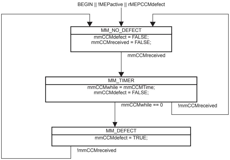
Figure 20-8—MEP Traffic Field Mismatch state machine
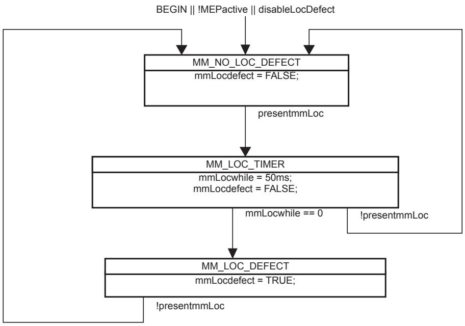
Figure 20-9—MEP Local Mismatch state machine
20.27 MP Loopback Responder variables
The following variables are local to the MP Loopback Responder state machine:
a) LBMreceived (20.27.1); and
b) LBMPDU (20.27.2).
20.27.1 LBMreceived
Boolean variable, set to true by an MP OpCode Demultiplexer when an LBM is received, and cleared by an MP Loopback Responder state machine.
20.27.2 LBMPDU
Structure. Loaded with the M_UNITDATA.indication or EM_UNITDATA.indication parameters of the LBM PDU received by the an MP OpCode Demultiplexer (19.2.7) when an LBM is received.
20.28 MP Loopback Responder procedures
The following procedures are defined for the Loopback Responder:
a) ProcessLBM() (20.28.1); and
b) xmitLBR() (20.28.2).
20.28.1 ProcessLBM()
Called by the MP Loopback Responder state machine whenever an LBM is received. ProcessLBM() processes the LBM in LBMPDU as follows:
a) If
1) the destination_address parameter contains an individual MAC address that does not match the MAC address of the receiving MP; and
2) the MP Loopback Responder state machine does not reside in a PBB-TE or SPBM VID MHF; ProcessLBM() discards the LBM and performs no further processing;
b) If the destination_address parameter contains a Group address and the MP Loopback Responder state machine resides in an MHF associated with neither PBB-TE nor SPBM (rather than in a MEP), ProcessLBM() discards the LBM and performs no further processing;
c) If the source_address parameter is a Group, and not an individual MAC address, ProcessLBM() discards the frame and performs no further processing.
d) ProcessLBM() shall process the LBM according to 20.51.4.2, and may validate the LBM according to 20.51.4.3, and discard any frames that fail the validation;
e) If the MP Loopback Responder state machine resides in a PBB-TE MEP and the LBM carries a PBB-TE MIP TLV, ProcessLBM() discards the LBM and performs no further processing;
f) If the MP Loopback Responder state machine resides in a PBB-TE or SPBM VID MHF and
1) There is no PBB-TE MIP TLV; or
2) There is a PBB-TE MIP TLV but the address carried in the MIP MAC address field does not match the MAC address of the receiving MIP;
ProcessLBM() forwards the LBM to the Passive MHF Multiplexer and performs no further processing;
g) Otherwise, ProcessLBM() calls xmitLBR() to generate and transmit an LBR.
20.28.2 xmitLBR()
Called by ProcessLBM() to transmit an LBR. xmitLBR() constructs an LBR from the LBM contained in LBMPDU, and transmits it to the Active SAP using an M_UNITDATA.request as follows:
a) Sets the destination_address parameter to the source_address of the received LBM if the MP is not associated with a PBB-TE MA; otherwise to
1) The value of the ESP-DA of the MA’s ESP that has the replying MEP’s MAC address [item i) in 12.14.7.1.3] in its ESP-SA field, if the MEP is a PBB-TE MEP; or otherwise to
2) The value carried in the Reverse MAC field contained in the PBB-TE MIP TLV of the received LBM, if this is a group MAC address; otherwise to
3) The source_address of the received LBM;
b) Sets the source_address parameter to the MAC address of the replying MP if the MP is not a PBB-TE MHF; or otherwise to
1) The destination_address of the received LBM if this is an individual MAC address; or otherwise to
2) The value carried in the Reverse MAC field contained in the PBB-TE MIP TLV of the received LBM;
c) If the LBM was received at a PBB-TE MHF and contains a PBB-TE MIP TLV, then the vlan_identifier in the LBR is set to the value in the Reverse VID field; otherwise, the vlan_identifier in the LBR is set to the value of the Primary VID associated with the replying MP [item d) in 12.14.7.1.3, item a) in 12.14.3.2.2, item c) in 12.14.5.3.2].
d) In the case of ECMP with flow filtering, the flow_hash parameter is set to zero and the time_to_live parameter is set to 63;
e) The priority parameter and the drop-eligible parameter are copied from the LBM.
f) Changes the OpCode field (21.4.3) from LBM to LBR;
g) Copies the remainder of the LBM’s mac_service_data_unit verbatim to the LBR; and
h) If the replying MP is a MEP, increments the LBR transmission counter by 1 [item ad) in 12.14.7.1.3].
20.29 MP Loopback Responder state machine
The MP Loopback Responder state machine implements the functions specified by the state diagram in Figure 20-10, using the variables in 20.27 and the procedures in 20.28. Although the definition of the MP Loopback Responders in 19.2.10 and 19.3.8 requires the instantiation of an MP Loopback Responder state machine in every MP, in practice, the number of MP Loopback Responder state machines implemented in a system cannot be determined from external observation of the system.
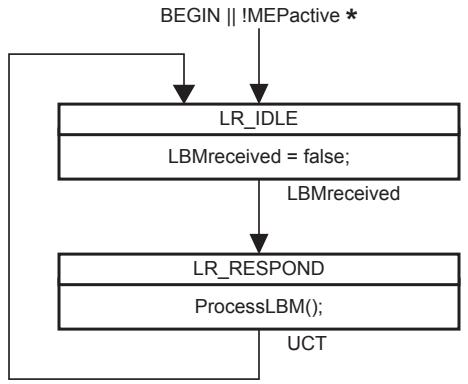
- MEPactive in a MEP; not present (always true) in an MHF
Figure 20-10—MP Loopback Responder state machine
20.30 MEP Loopback Initiator variables
The following variables are local to the MEP Loopback Initiator transmit state machine and the MEP Loopback Initiator receive state machine:
a) LBMsToSend (20.30.1);
b) nextLBMtransID (20.30.2);
c) expectedLBRtransID (20.30.3);
d) LBIactive (20.30.4);
e) xmitReady (20.30.5);
f) LBRreceived (20.30.6); and
g) LBRPDU (20.30.7).
20.30.1 LBMsToSend
The integer number of LBMs that the MEP Loopback Initiator transmit state machine is to transmit. Set by a management operation [item c) in 12.14.7.3.2]. Setting this variable to a nonzero value starts transmission of LBMs. LBMsToSend is decremented by 1 by the MEP Loopback Initiator transmit state machine with each transmission.
20.30.2 nextLBMtransID
The value to place in the Loopback Transaction Identifier field of the next LBM transmitted by xmitLBM(). nextLBMtransID is incremented by 1 by the MEP Loopback Initiator transmit state machine with each transmission. This variable is available as a managed object [item x) in 12.14.7.1.3].
20.30.3 expectedLBRtransID
The value expected to be found in the Loopback Transaction Identifier field of the next LBR received by ProcessLBR(). Altered by ProcessLBR() (see 20.33.1).
20.30.4 LBIactive
A Boolean flag indicating whether the MEP Loopback Initiator transmit state machine is (true) or is not (false) actively engaged in a requested operation. Set to true by the MEP Loopback Initiator transmit state machine after LBMsToSend is set to a nonzero value by a management operation. Reset to false by the MEP Loopback Initiator transmit state machine 5 s after the last LBM is transmitted or the last LBR is received, whichever comes later.
20.30.5 xmitReady
A Boolean flag set to true by the Bridge Port to indicate that another LBM can be transmitted. Reset to false by the MEP Loopback Initiator transmit state machine.
20.30.6 LBRreceived
Boolean flag. Set by the MEP Equal OpCode Demultiplexer (19.2.7) when an LBR at the MEP’s MD Level is received. Cleared by the MEP Loopback Initiator receive state machine.
20.30.7 LBRPDU
Structure. Loaded with the M_UNITDATA.indication or EM_UNITDATA.indication parameters of the LBR PDU received by the MEP Equal OpCode Demultiplexer (19.2.7) when an LBR at the MEP’s MD Level is received.
20.31 MEP Loopback Initiator transmit procedures
The following procedure is local to the MEP Loopback Initiator transmit state machine:
a) xmitLBM() (20.31.1).
20.31.1 xmitLBM()
xmitLBM() is called by the MEP Loopback Initiator transmit state machine. It constructs and transmits an LBM on the Active SAP using an M_UNITDATA.request as follows:
a) Sets the destination_address parameter from the appropriate managed object [item b) in 12.14.7.3.2] or in the case of an SPBM VID MEP [item g) in 12.14.7.3.2]. If the MEP is configured on a PBB-TE MA, the destination_address parameter is set to the MAC address indicated by the value of the ESP-DA field of the MA’s ESP that has the MEP’s MAC address indicated in its ESP-SA field;
b) Sets the source_address parameter to the MAC address of the MEP [item i) in 12.14.7.1.3];
c) Sets the priority and drop_eligible parameters from the appropriate managed object [item e) in 12.14.7.3.2];
d) In the case of ECMP with flow filtering, the flow_hash parameter is set from the appropriate managed object [item h) in 12.14.7.3.2] and the time_to_live parameter is set to 63;
e) Copies nextLBMtransID (20.30.2) to the Loopback Transaction Identifier field (21.7.3) of the LBM;
f) If the MEP is configured on a PBB-TE MA, constructs a PBB-TE MIP TLV using in the MIP MAC address field the target address parameter from the appropriate managed object [item b) in 12.14.7.3.2] and in the Reverse VID field the parameter [item f) in 12.14.7.3.2]; if the MEP is a root in a point-to-multipoint TESI, the Reverse MAC field is also included in the PBB-TE MIP TLV carrying the ESP-SA value of any of the MA’s point-to-point ESPs; if the MEP is a leaf in a pointto-multipoint TESI, the Reverse MAC field carries the ESP-DA of the point-to-multipoint ESP; the PBB-TE MIP TLV is not used if the LBM target address in 12.14.7.3.2 is associated with any of the values in the ESP-DA field of the monitored MA’s ESPs;
g) If the MEP is configured on an SPBM VID MA, constructs a PBB-TE MIP TLV using in the MIP MAC address field the target address parameter from the appropriate managed object [item b) in 12.14.7.3.2];
h) Constructs a Data TLV from the appropriate managed object [item d) in 12.14.7.3.2] if and only if that managed object has a nonzero length;
i) As controlled by the managed objects item e) in 12.14.3.1.3, item d) in 12.14.5.1.3, and item d) in 12.14.6.1.3, places a Sender ID TLV (21.5.3), identifying the transmitting system, in the LBM; and
j) Increments nextLBMtransID (20.30.2) by 1, wrapping around from $2 ^ { 3 2 } - 1$ to 0.
20.32 MEP Loopback Initiator transmit state machine
A MEP creates a single instance of the MEP Loopback Initiator transmit state machine. The MEP Loopback Initiator transmit state machine implements the function specified by the state diagram in Figure 20-11 and the procedures in 20.31. It shares with the MEP Loopback Initiator receive state machine the variable declarations in 20.30.
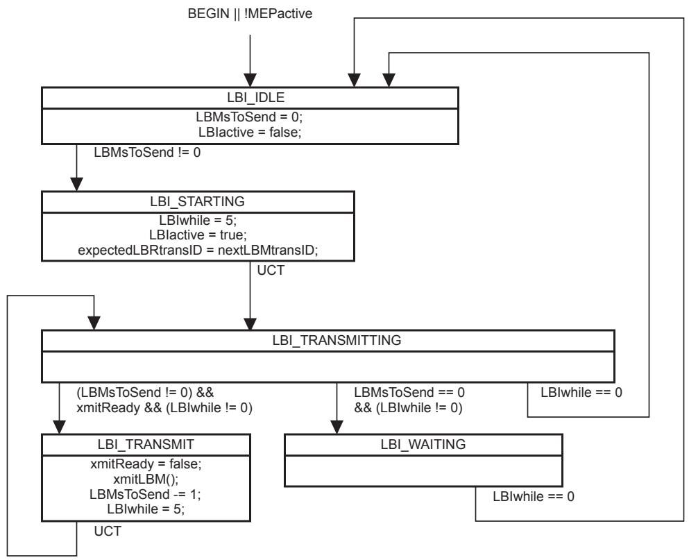
Figure 20-11—MEP Loopback Initiator transmit state machine
20.33 MEP Loopback Initiator receive procedures
The following procedure is local to the MEP Loopback Initiator receive state machine:
a) ProcessLBR() (20.33.1).
20.33.1 ProcessLBR()
Called by the MEP Loopback Initiator receive state machine whenever an LBR is received. ProcessLBR() processes the LBR in LBRPDU as follows:
a) If the I/G bit of the source_address indicates a Group address, or if the destination_address does not match the MAC address of the receiving MP, ProcessLBR() discards the received LBR.
b) ProcessLBR() shall process the LBM according to 20.51.4.2, and may validate the received LBR according to 20.51.4.3, and discard it if invalid.
c) If the LBR is not discarded, and if and only if LBIactive is true, the Loopback Transaction Identifier field of the LBR is compared to expectedLBRtransID:
1) If the two values are equal, then the number of correct LBRs received [item y) in 12.14.7.1.3] is incremented by 1;
2) If the two values are unequal, then the value from the received Loopback Transaction Identifier field is copied into expectedLBRtransID, and the number of incorrect LBRs received [item z) in 12.14.7.1.3] is incremented by 1;
3) Regardless of whether the two values were equal, expectedLBRtransID is then incremented by 1.
d) ProcessLBR() may perform a bit-by-bit comparison of the received LBR against the LBM with the matching Loopback Transaction Identifier, except for the OpCode field, and increment a managed object [item aa) in 12.14.7.1.3] if they do not match.
20.34 MEP Loopback Initiator receive state machine
A MEP creates a single instance of the MEP Loopback Initiator receive state machine. The MEP Loopback Initiator receive state machine implements the function specified by the state diagram in Figure 20-12 and the procedures in 20.33. It shares with the MEP Loopback Initiator transmit state machine the variable declarations in 20.30.
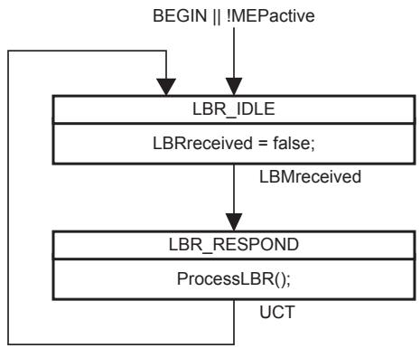
Figure 20-12—MEP Loopback Initiator receive state machine
20.35 MEP Fault Notification Generator variables
The following variables are local to the MEP Fault Notification Generator state machine:
a) fngPriority (20.35.1);
b) fngDefect (20.35.2);
c) fngAlarmTime (20.35.3);
d) fngResetTime (20.35.4);
e) someRMEPCCMdefect (20.35.5);
f) someMACstatusDefect (20.35.6);
g) someRDIdefect (20.35.7);
h) highestDefectPri (20.35.8); and
i) highestDefect (20.35.9).
20.35.1 fngPriority
An integer specifying the priority of the last defect reported in a Fault Alarm. fngPriority takes the same values as highestDefectPri (20.35.8).
20.35.2 fngDefect
An enumerated value specifying the last defect reported in a Fault Alarm. fngDefect takes the same values as highestDefect (20.35.9).
20.35.3 fngAlarmTime
The time that one or more defects must be present before a Fault Alarm is issued. Default value 2.5 s. Also a managed object [item l) in 12.14.7.1.3].
20.35.4 fngResetTime
The time, after a Fault Alarm, that no defects must be present before another Fault Alarm is enabled. Default value 10 s. Also a managed object [item m) in 12.14.7.1.3].
20.35.5 someRMEPCCMdefect
A Boolean indicating the aggregate state of the Remote MEP state machines. True indicates that at least one of the Remote MEP state machines is not receiving valid CCMs from its remote MEP, and false that all Remote MEP state machines are receiving valid CCMs. someRMEPCCMdefect is the logical OR of all of the rMEPCCMdefect variables for all of the Remote MEP state machines on this MEP. This variable is readable as a managed object [item q) in 12.14.7.1.3].
20.35.6 someMACstatusDefect
A Boolean indicating that one or more of the remote MEPs is reporting a failure in its Port Status TLV (21.5.4) or Interface Status TLV (21.5.5). It is true either if some remote MEP is reporting that its interface is not isUp (i.e., at least one remote MEP’s interface is unavailable), or if all remote MEPs are reporting a Port Status TLV that contains some value other than psUp (i.e., all remote MEPs’ Bridge Ports are not forwarding data). It is thus the logical OR of the following two terms:
a) The logical AND, across all remote MEPs, of the rMEPportStatusDefect variable; OR
b) The logical OR, across all remote MEPs, of the rMEPinterfaceStatusDefect variable.
This variable is readable as a managed object [item p) in 12.14.7.1.3].
20.35.7 someRDIdefect
A Boolean indicating the aggregate health of the remote MEPs. True indicates that at least one of the Remote MEP state machines is receiving valid CCMs from its remote MEP that has the RDI bit set, and false that no Remote MEP state machines are receiving valid CCMs with the RDI bit set. someRDIdefect is the logical OR of all of the rMEPlastRDI and rMEPlastRDI[i] variables for all of the Remote MEP state machines on this MEP. This variable is readable as a managed object [item o) in 12.14.7.1.3].
20.35.8 highestDefectPri
An integer value indicating the priority of the defect named in the variable highestDefect. See also Table 20-1.
20.35.9 highestDefect
An enumerated value indicating the highest priority defect among the variables xconCCMdefect (20.23.3), errorCCMdefect (20.21.3), someRMEPCCMdefect (20.35.5), someMACstatusDefect (20.35.6), and someRDIdefect (20.35.7), as limited by lowestAlarmPri (20.9.5). This variable is readable as a managed object [item c) in 12.14.7.7.2]. The variables, their priorities, and the enumerated values of highestDefect are shown in Table 20-1.
20.36 MEP Fault Notification Generator procedures
The following procedure is local to the MEP Fault Notification Generator state machine:
a) xmitFaultAlarm() (20.36.1).
20.36.1 xmitFaultAlarm()
Transmits a Fault Alarm (12.14.7.7). The identity of the MEP and the variable fngDefect (20.35.2), specifying the cause of the Fault Alarm, are transmitted in the Fault Alarm PDU. The format and method of transmission of the Fault Alarm is not specified in this standard.
20.37 MEP Fault Notification Generator state machine
A MEP creates a single instance of the MEP Fault Notification Generator state machine. The MEP Fault Notification Generator state machine implements the function specified by the state diagram in Figure 20-13, the variables in 20.35, and the procedure in 20.36. The current state of the MEP Fault Notification Generator state machine is available in a managed object [item f) in 12.14.7.1.3].
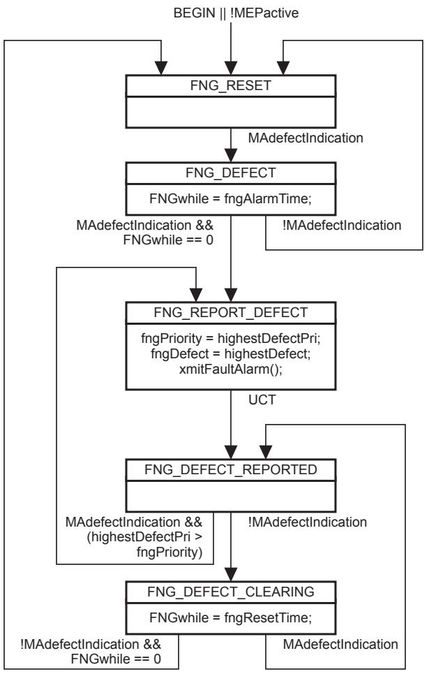
Figure 20-13—MEP Fault Notification Generator state machine
20.38 MEP Mismatch Fault Notification Generator variables
The following variables are local to the MEP Mismatch Fault Notification Generator state machine for a PBB-TE MEP or Infrastructure Segment MEP implementing the Traffic field (21.6.1.4):
a) mfngAllowed (20.38.1)
b) mmdefectIndication (20.38.2)
c) mfngAlarmTime (20.38.3)
d) mfngResetTime (20.38.4)
20.38.1 mfngAllowed
A Boolean indicating the mismatch defect is allowed to generate a Fault Alarm. Its value is configurable as a managed object [item ag) in 12.14.7.1.3].
20.38.2 mmdefectIndication
A Boolean indicating the presence of the mismatch defect that is allowed to generate a Fault Alarm. It corresponds to the logical AND of the variables mfngAllowed (20.38.1), mmCCMdefect (20.25.2), and mmLocdefect (20.25.5).
20.38.3 mfngAlarmTime
The time that one or more defects must be present before a mismatch Fault Alarm is issued. Default value 2.5 s. Also a managed object [item l) in 12.14.7.1.3].
20.38.4 mfngResetTime
The time, after a mismatch Fault Alarm, that no defects must be present before another mismatch Fault Alarm is enabled. Default value 10 s. Also a managed object [item m) in 12.14.7.1.3].
20.39 MEP Mismatch Fault Notification Generator procedures
The following procedure is local to the MEP Mismatch Fault Notification Generator state machine for a PBB-TE MEP or Infrastructure Segment MEP implementing the Traffic field (21.6.1.4):
a) xmitFaultAlarm() (20.36.1)
20.39.1 xmitFaultAlarm()
Transmits a Fault Alarm (12.14.7.7). The identity of the MEP and a value indicating that the cause of the Fault Alarm is a mismatch defect, are transmitted in the Fault Alarm PDU. The format and method of transmission of the Fault Alarm is not specified in this standard.
20.40 MEP Mismatch Fault Notification Generator state machine
A PBB-TE MEP or Infrastructure Segment MEP implementing the Traffic field (21.6.1.4) creates a single instance of the MEP Mismatch Fault Notification Generator state machine. The MEP Mismatch Fault Notification Generator state machine implements the function specified by the state diagram in Figure 20-14, the variables in 20.38, and the procedure in 20.39. The current state of the MEP Mismatch Fault Notification Generator state machine is available in a managed object [item ak) in 12.14.7.1.3].
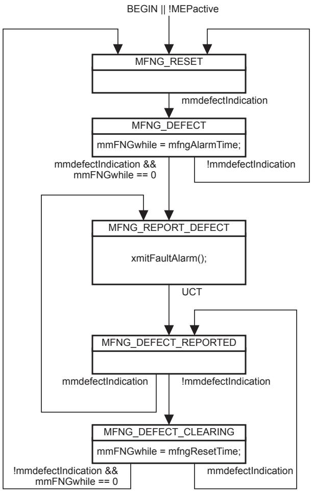
Figure 20-14—MEP Mismatch Fault Notification Generator state machine
20.41 MEP Linktrace Initiator variables
The following variables are local to the MEP Linktrace Initiator variables:
a) nextLTMtransID (20.41.1); and
b) ltmReplyList (20.41.2).
20.41.1 nextLTMtransID
The value to place in the LTM Transaction Identifier of the next LTM transmitted by xmitLTM(). nextLTMtransID is incremented by 1 by the MEP Linktrace Initiator variables with each transmission. This variable is also a managed object [item ab) in 12.14.7.1.3].
20.41.2 ltmReplyList
The list of recently-issued LTMs and their corresponding LTRs. An LTM entry, with no attached LTR entries, is added to this list by xmitLTM() each time an LTM is transmitted, and an LTR entry is attached to an LTM entry in this list, by ProcessLTR(), each time an LTR corresponding to an LTM in the list is received. The MEP does not remove any entry from this list before 5 s have elapsed since the transmission of the corresponding LTM, unless the addition of another LTM or LTR entry would exceed the maximum resources allocated for this list. This variable constitutes the Linktrace database for a given MEP and is also a managed object (12.14.7.5.3).
Each LTR entry contains the following variables:
a) ltrFlags (20.41.2.1);
b) ltrReplyTTL (20.41.2.2);
c) ltrLastEgressId (20.41.2.3);
d) ltrNextEgressId (20.41.2.4);
e) ltrRelayAction (20.41.2.5);
f) ltrIngressAction (20.41.2.6);
g) ltrIngressAddress (20.41.2.7);
h) ltrIngressPortIdSubtype (20.41.2.8);
i) ltrIngressPortId (20.41.2.9);
j) ltrEgressAction (20.41.2.10);
k) ltrEgressAddress (20.41.2.11);
l) ltrEgressPortIdSubtype (20.41.2.12);
m) ltrEgressPortId (20.41.2.13);
n) ltrSenderIdTlv (20.41.2.14); and
o) ltrOrgSpecTlv (20.41.2.15).
20.41.2.1 ltrFlags
The bit string returned in the Flags field (21.9.1) of the LTR, including the FwdYes and TerminalMEP bits.
20.41.2.2 ltrReplyTTL
The integer value returned in the Reply TTL field (21.9.4) of the LTR.
20.41.2.3 ltrLastEgressId
The octet string returned in the Last Egress Identifier field (21.9.7.1) of the LTR Egress Identifier TLV.
20.41.2.4 ltrNextEgressId
The integer value returned in the Next Egress Identifier field (21.9.7.2) of the LTR Egress Identifier TLV.
20.41.2.5 ltrRelayAction
The enumerated value returned in the Relay Action field (21.9.5) of the LTR. The enumerated values are listed in Table 21-28.
20.41.2.6 ltrIngressAction
The enumerated value returned in the Ingress Action field (21.9.8.1) of the Reply Ingress TLV (21.9.8) of the LTR. The enumerated values are listed in Table 21-31. An enumerated value of 0 indicates that no Reply Ingress TLV was returned in the LTR.
20.41.2.7 ltrIngressAddress
The MAC address of the MP on the Ingress Port. Contents are undefined if no Reply Ingress TLV was returned in the LTR.
20.41.2.8 ltrIngressPortIdSubtype
An enumerated value as specified by IEEE Std 802.1AB, indicating the format of ltrIngressPortId. Contents are undefined if no Reply Ingress TLV was returned in the LTR.
20.41.2.9 ltrIngressPortId
An octet string as specified by IEEE Std 802.1AB, identifying the Ingress Port, in the format identified in ltrIngressPortIdSubtype.
20.41.2.10 ltrEgressAction
The enumerated value returned in the Egress Action field (21.9.9.1) of the Reply Egress TLV (21.9.9) of the LTR. The enumerated values are listed in Table 21-33. A value of 0 indicates that no Reply Egress TLV was returned in the LTR.
20.41.2.11 ltrEgressAddress
The MAC address of the MP on the Egress Port. Contents are undefined if no Reply Egress TLV was returned in the LTR.
20.41.2.12 ltrEgressPortIdSubtype
An enumerated value as specified by IEEE Std 802.1AB, indicating the format of ltrEgressPortId. Contents are undefined if no Reply Ingress TLV was returned in the LTR.
20.41.2.13 ltrEgressPortId
An octet string as specified by IEEE Std 802.1AB, identifying the Egress Port, in the format identified in ltrEgressPortIdSubtype.
20.41.2.14 ltrSenderIdTlv
An octet string identifying the transmitting system, as received in the Sender ID TLV (21.5.3), if one was present in the LTR.
20.41.2.15 ltrOrgSpecTlv
An octet string containing the Organization-Specific TLVs (21.5.2), if any were present in the LTR.
20.42 MEP Linktrace Initiator procedures
The following procedure is local to the MEP Linktrace Initiator:
a) xmitLTM() (20.42.1).
20.42.1 xmitLTM()
xmitLTM() is called whenever the Transmit Linktrace Message management operation (12.14.7.4) is invoked. It constructs and transmits an LTM on the Active SAP, or on the MEP LTI SAP if the operation is invoked on an Up MEP, using an M_UNITDATA.request as follows:
a) Sets the destination_address parameter to the value from Table 8-16 corresponding to the MEP’s MD Level. If the MEP is configured on a PBB-TE MA, the destination_address parameter is the MAC address indicated by the value of the ESP-DA field of the MA’s ESP that has the MEP’s MAC address indicated in its ESP-SA field. If the MEP is configured on an SPBM VID MA, the destination_address parameter is set to the value configured in the LTM management request [item f) in 12.14.7.4.2];
b) Sets the source_address parameter and Original MAC Address field (21.8.5) to the MAC address of the MEP [item i) in 12.14.7.1.3];
c) If the MEP is configured on a PBB-TE MA, constructs a PBB-TE MIP TLV using in the MIP MAC address field a null field and in the Reverse VID field the parameter [item e) in 12.14.7.4.2]; if the MEP is a root in a point-to-multipoint TESI, the Reverse MAC field is also included in the PBB-TE MIP TLV carrying the ESP-SA value of any of the MA’s point-to-point ESPs; if the MEP is a leaf in a point-to-multipoint TESI, the Reverse MAC field carries the ESP-DA of the point-to-multipoint ESP;
d) In the case of ECMP with flow filtering, the flow_hash parameter is set to the value specified in the appropriate managed object [item g) in 12.14.7.4.2] and the time_to_live parameter is set to 63.;
e) Sets the priority parameter to the same value as for CCMs [item h) in 12.14.7.1.3];
f) Copies nextLTMtransID [item ab) in 12.14.7.1.3] to the LTM Transaction Identifier field (21.8.3) of the LTM;
g) Sets the LTM Egress Identifier TLV (21.8.8) to a value that is unique among all Bridges in the Management Domain.
h) Sets the Target MAC Address field (21.8.6) from the appropriate managed object [item c) in 12.14.7.4.2];
i) Sets the LTM TTL field (21.8.4) from the appropriate managed object [item d) in 12.14.7.4.2];
j) Sets the UseFDBonly bit of the Flags field (21.8.1) from the appropriate managed object [item b) in 12.14.7.4.2], and sets all other bits of the Flags field to 0;
k) As controlled by the managed objects item e) in 12.14.3.1.3, item d) in 12.14.5.1.3, and item d) in 12.14.6.1.3, places a Sender ID TLV (21.5.3), identifying the transmitting system, in the LTM;
l) Creates a new entry in the ltmReplyList variable (20.41.2) for this LTM, identified by the LTM Transaction Identifier in nextLTMtransID (20.41.1); and
m) Increments nextLTMtransID (20.41.1) by 1, wrapping around from $2 ^ { 3 2 } - 1 \mathrm { t o } 0 .$
If the addition of this LTM entry would exceed the resources allocated to ltmReplyList, then the oldest LTM entries in ltmReplyList are deleted until sufficient resources are available to hold the new LTM entry.
20.43 MEP Linktrace Initiator receive variables
The following variables are local to the MEP Linktrace Initiator receive state machine:
a) LTRreceived (20.43.1); and
b) LTRPDU (20.43.2).
20.43.1 LTRreceived
Boolean flag. Set by the MEP Equal OpCode Demultiplexer (19.2.7) when an LTR at the MEP’s MD Level is received. Cleared by the MEP Linktrace Initiator receive state machine.
20.43.2 LTRPDU
Structure. Loaded with the M_UNITDATA.indication or EM_UNITDATA.indication parameters of the LTR PDU received by the MEP Equal OpCode Demultiplexer (19.2.7) when an LTR at the MEP’s MD Level is received.
20.44 MEP Linktrace Initiator receive procedures
The following procedure is local to the MEP Linktrace Initiator receive state machine:
a) ProcessLTR() (20.44.1).
20.44.1 ProcessLTR()
The ProcessLTR() procedure is called by the MEP Linktrace Initiator receive state machine whenever an LTR is received, and processes the LTR contained in the LTRPDU variable as follows:
a) If the destination_address of the LTR does not match the MAC address of the MEP, or if the LTR fails the validation criteria of 20.51.4, ProcessLTR() shall discard the LTR without counting it, and no further processing takes place.
b) Otherwise, if the LTR Transaction Identifier field matches an LTM entry in the ltmReplyList variable, then a new LTR entry is attached to that LTM entry, containing the information returned in the LTR.
c) Otherwise, the number of unexpected LTRs received [item ac) in 12.14.7.1.3] is incremented by 1.
If the addition of this LTR entry would exceed the resources allocated to ltmReplyList, then the oldest LTM entries in ltmReplyList (the oldest LTR entries, if only one LTM entry is present) are deleted until sufficient resources are available to hold the new LTR entry.
20.45 MEP Linktrace Initiator receive state machine
One instance of the MEP Linktrace Initiator receive state machine is instantiated by each MEP Linktrace Initiator. The MEP Linktrace Initiator receive state machine implements the function specified by the state diagram in Figure 20-15, the variables in 20.43, and the procedures in 20.44.
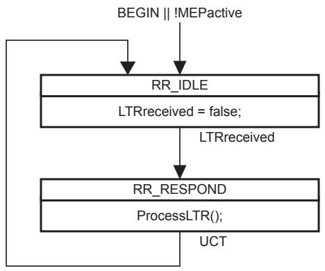
Figure 20-15—MEP Linktrace Initiator receive state machine
20.46 Linktrace Responder variables
The following variables are local to the Linktrace Responder:
a) nPendingLTRs (20.46.1);
b) LTMreceived (20.46.2); and
c) LTMPDU (20.46.3).
20.46.1 nPendingLTRs
An integer value used to track the number of LTRs that have been enqueued for transmission by enqueLTR() and not yet transmitted by xmitOldestLTR(). Can be reset to 0 by clearPendingLTRs().
20.46.2 LTMreceived
A Boolean value set when a valid LTM is received and cleared by the LTM Receiver state machine.
20.46.3 LTMPDU
Structure. Loaded with the M_UNITDATA.indication or EM_UNITDATA.indication parameters of the LTM PDU received by the MEP Equal OpCode Demultiplexer (19.2.7) when an LTM at the MEP’s MD Level is received.
20.47 LTM Receiver procedures
The procedures local to the LTM Receiver state machine are
a) ProcessLTM() (20.47.1);
b) clearPendingLTRs() (20.47.2);
c) ForwardLTM() (20.47.3); and
d) enqueLTR() (20.47.4).
20.47.1 ProcessLTM()
Called by the LTM Receiver state machine when an LTM is received and processes the LTM contained in the LTMPDU, making the decision whether to call ForwardLTM() to forward the LTM, and whether to call enqueLTR() to enqueue an LTR for transmission, according to 20.3.2. The received LTM is first validated.
a) ProcessLTM() validates the received LTM according to 20.51.3. If the LTM is invalid, no further validation steps are performed.
b) Otherwise, the LTM TTL field (21.8.4) of the received LTM is examined. If its value is 0, the LTM is invalid, and no further validation steps are performed.
c) Otherwise, if the vlan_identifier identifies an ESP-VID or SPBM VID the LTM is valid, and no further validation steps are performed.
d) Otherwise, if the destination_address parameter of the LTM is a Group address, the LTM is valid, and no further validation steps are performed.
e) Otherwise, if both
1) The LTM was received from a Linktrace SAP, and not from the originating Up MEP through its MEP LTI SAP; and
2) The destination_address parameter of the LTM is the individual MAC address of the receiving MP [item i) in 12.14.7.1.3 for a MEP, the MAC address of the Bridge Port for an MHF]; then the LTM is valid.
f) Otherwise, the LTM is invalid.
20.47.1.1 LTM paths through a Bridge
If the LTM is valid, processing proceeds according to the following subclauses. Otherwise, ProcessLTM() discards the LTM, and no further processing takes place.
Figure 20-16 illustrates a number of (but not all) possible paths taken by an LTM through a Bridge. The gray circles indicate the processing of an LTM and the possible forwarding of a modified copy of the LTM. The LTR path is not shown.
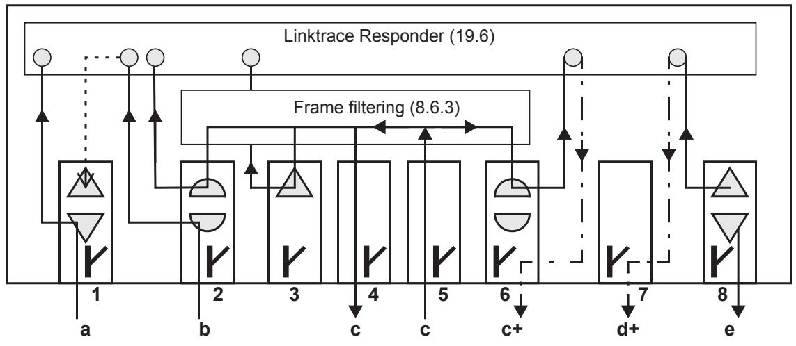
Figure 20-16—Linktrace Responder, MEPs, MHFs, and LOMs
NOTE—All of the MPs shown in Figure 20-16 are at the same MD Level.
a) An LTM is detected by a Down MEP as it enters Port 1. It is deflected to the Linktrace Responder through the MEP Linktrace SAP.
b) An LTM is detected by an MHF as it enters Port 2. It is deflected to the Linktrace Responder through the MHF Linktrace SAP, which determines that the Target MAC Address would be forwarded out Port 1, on which there is a MEP. The LTM is not actually forwarded to the MEP.
c) An LTM enters on Port 5, which has no MHF, and if it is a multicast, the LTM is distributed to Ports 2, 3, 4, and 6 by the Frame filtering function (8.6.3). The original, unaltered LTM passes out Port 4. The Up MEP in Port 3 and the MHFs in Ports 2 and 6 deliver the LTM to the Linktrace Responder. The Linktrace Responder discards the LTMs received on Port 2 and 3, but forwards an updated version of the LTM through the LOM on Port 6.
d) The Up MEP on Port 8 generates an LTM, which it forwards to the Linktrace Responder. The Linktrace Responder decides to forward an updated version of the LTM through the LOM on Port 7. (The Linktrace Responder might equally well have forwarded it through some other Port’s MHF.)
e) The Down MEP on Port 8 generates an LTM and transmits it through its Active SAP to the LAN attached to Port 8.
If an LTM is forwarded, the forwarding takes place immediately. If an LTR is generated in response to the LTM, it is enqueued for later transmission by the LTR Transmitter state machine (20.50).
20.47.1.2 Ingress Port, vlan_identifier, and Egress Port determination
In 20.3.2 and Figure 20-16, case a) through case e) all require ProcessLTM() to determine the Ingress and Egress Ports for this received LTM. The Ingress Port is the Bridge Port on which the LTM entered the Bridge, whether through a MEP, an MHF, or an LOM. In case d), where an LTM is generated by an Up
MEP and passed through a MEP LTI SAP to the Linktrace Responder, the Ingress Port is the Bridge Port of the originating MEP.
If received from an EISS SAP, the vlan_identifier of the received LTM is included in the EM_UNITDATA.indication. If received from an ISS SAP, the vlan_identifier of the received LTM is that configured in the MEP, MHF, or LOM that received the LTM, or if none, is the PVID (IEEE Std 802.1AC) of the Ingress Port.
The Egress Port is the Bridge Port on which a data frame whose destination_address is equal to the Target MAC Address carried in the LTM, or in the case of an MP associated with a PBB-TE MA, the destination_address of the LTM, and whose vlan_identifier matched that of the LTM, would be forwarded. This determination is made in two steps:
a) ProcessLTM() first queries the FDB (8.8). The set of potential transmission ports, normally created by Active topology enforcement (8.6.1), is the set of all Bridge Ports that are both in the active set of the vlan_identifier of the LTM and that are in the Forwarding state for that vlan_identifier, except that the Ingress Port is excluded from the set. The query uses the Target MAC Address field of the LTM as the destination_address of the lookup, the Original MAC Address field of the LTM as the source_address, and the vlan_identifier of the LTM. In the case of an MP associated with a PBB-TE or SPBM VID MA, the query uses the destination_address and the vlan_identifier of the LTM as the corresponding parameters for the lookup. If the MP is associated with ECMP with flow filtering, the query uses the flow_hash parameter in the lookup process, when required. The output from this query is a (perhaps reduced) set of potential transmission ports. If the resultant set contains one and only one Bridge Port, that Bridge Port is the Egress Port, and item b) is not performed. If the resultant set contains more than one Bridge Port, and the MP is associated with a PBB-TE MA, those Bridge Ports are all Egress Ports, and step b is not performed.
NOTE 1—If there are only two Bridge Ports that are members of the VID’s member set, the Ingress Port was one of those two Bridge Ports, and the Ingress Port is not connected to a shared medium, then this step can identify the Egress Port even if the FDB is not used for this vlan_identifier.
NOTE 2—This query cannot produce an Egress Port that is the same as the Ingress Port, since the Ingress Port is not included in the set of potential transmission ports.
b) If the FDB could not produce a unique Egress Port, and the MPs serving the vlan_identifier of the LTM are maintaining a MIP CCM Database, and the UseFDBonly bit of the Flags field of the LTM is 0, then ProcessLTM() queries the MIP CCM Database to see whether the target MAC address and vlan_identifier have been retained in that database. If so, and if the Port number in the MIP CCM Database is not the same as the Ingress Port, that Port number identifies the Egress Port.
It is possible that neither of these two steps are able to determine the Egress Port; when a unique Egress Port cannot be determined, an LTM is never forwarded by MHFs other than PBB-TE MHFs or SPBM VID MHFs. PBB-TE MHFs associated with point-to-multipoint TESIs forward LTMs even if multiple Egress Ports are identified. MHFs associated with SPBM VID MAs forward group addressed LTMs even if multiple Egress Ports are identified.
20.47.1.3 LTM is received by a Down MEP
In case a) in 20.47.1.1, illustrated in Figure 20-16, the LTM is received by a Down MEP, and delivered to the Linktrace Responder through its MEP Linktrace SAP (19.2.14). In this case, ProcessLTM() performs the following steps:
a) If the Target MAC Address carried in the LTM is the MAC address of the receiving MEP, then the LTM has reached its target. ProcessLTM() calls enqueLTR() (20.47.4) to enqueue an LTR for the MEP Linktrace SAP of the receiving Down MEP.
b) Otherwise, if the spanning tree state of the Bridge Port and vlan_identifier of the LTM is not Forwarding, the LTM is discarded and no further processing takes place.
c) Otherwise, the Ingress and Egress Ports are determined according to 20.47.1.2. If a unique Egress Port cannot be determined, then the LTM is discarded, and no further processing takes place.
d) Otherwise, i.e., a unique Egress Port was found, ProcessLTM() calls enqueLTR() (20.47.4) to enqueue an LTR for the Linktrace SAP through which the LTM was received. The LTM is discarded, and no further processing takes place.
20.47.1.4 LTM is received by a Down MHF or originated by an Up MEP
In case b) in 20.47.1.1, illustrated in Figure 20-16, the LTM is received by a Down MHF. In case d) in 20.47.1.1, illustrated in Figure 20-16, the LTM is originated by an Up MEP. In either case, ProcessLTM() performs the following steps:
a) If the LTM was generated by an Up MEP, item b) and item c) are skipped, and processing continues with item d), as follows.
b) If the Target MAC Address carried in the LTM is the MAC address of the receiving MHF, then the LTM has reached its target. ProcessLTM() calls enqueLTR() (20.47.4) to enqueue an LTR for the Linktrace SAP through which the LTM was received. The LTM is discarded, and no further processing takes place.
c) Otherwise, if the spanning tree state of the Bridge Port and vlan_identifier of the LTM is not Forwarding, the LTM is discarded and no further processing takes place.
NOTE—This test prevents spurious LTRs from being generated on Backup Ports on a shared medium.
d) Otherwise, the Ingress and Egress Ports are determined according to 20.47.1.2. If an Egress Port cannot be determined, then the LTM is discarded, and no further processing takes place.
e) There are three cases for further processing of the LTM, depending on whether, as it passes through the Egress Port, a frame with the LTM’s vlan_identifier would first encounter an Up MEP, an Up MHF, or neither. These described in case f), case g), case h), and case i), as follows.
f) If an Up MHF would be encountered on the Egress Port, then
1) ProcessLTM() calls enqueLTR() (20.47.4) to enqueue an LTR for the MHF Linktrace SAP of the Egress Port’s Up MHF.
2) If the target MAC address carried in the LTM is the Egress Port Up MHF’s MAC address, then the LTM is discarded, and no further processing takes place.
3) Otherwise, if the LTM TTL field equals 0 or 1, the LTM is discarded and no further processing takes place.
4) Otherwise, ProcessLTM() calls ForwardLTM() (20.47.3) to forward an altered copy of the LTM through the LOM Linktrace SAP of the LOM on the identified Egress Port.
g) If an Up MEP at the MD Level of the LTM would be encountered on the Egress Port, then
1) ProcessLTM() calls enqueLTR() (20.47.4) to enqueue an LTR for the MHF Linktrace SAP of the Ingress Port’s Down MHF, or the MEP LTI SAP of the Up MEP, that delivered the LTM to the Linktrace Responder.
2) The LTM is discarded, and no further processing takes place.
h) Otherwise, if an Up MEP higher than the MD Level of the LTM would be encountered on the Egress Port, then the LTM is discarded, and no further processing takes place.
i) If neither an Up MHF, nor an Up MEP at an MD Level higher than or equal to the LTM, would be encountered on the Egress Port, then
1) ProcessLTM() calls enqueLTR() (20.47.4) to enqueue an LTR for the MHF Linktrace SAP of the Ingress Port’s Down MHF.
2) If the LTM TTL field equals 0 or 1, the LTM is discarded and no further processing takes place.
3) Otherwise, ProcessLTM() calls ForwardLTM() (20.47.3) to forward an altered copy of the LTM through the LOM Linktrace SAP of the LOM that a frame with the LTM’s vlan_identifier would first encounter when passing out through the identified Egress Port.
20.47.1.5 LTM is received by an Up MEP
In case c) in 20.47.1.1, illustrated in Figure 20-16, an LTM enters a Bridge on a Bridge Port that has no MEP or MHF and therefore only an LOM. The LTM can therefore be received by an Up MEP such as the one on Port 3 of Figure 20-16. Processing of an LTM received on an Up MEP proceeds as follows:
a) If the Target MAC Address carried in the LTM is the MAC address of the receiving MEP, then the LTM has reached its target. ProcessLTM() calls enqueLTR() (20.47.4) to enqueue an LTR for the MEP Linktrace SAP of the receiving Up MEP. The LTM is discarded, and no further processing takes place.
b) Otherwise, the Ingress and Egress Ports are determined according to 20.47.1.2. If the Egress Port cannot be determined, or if the Egress Port is not the Bridge Port on which the receiving MEP is configured, then the LTM is discarded and no further processing takes place.
c) Otherwise, (i.e., the Egress Port is that of the receiving Up MEP) ProcessLTM() calls enqueLTR() (20.47.4) to enqueue an LTR for the MEP Linktrace SAP of the receiving Up MEP. The LTM is then discarded.
20.47.1.6 LTM is received by an Up MHF
In case c) in 20.47.1.1, illustrated in Figure 20-16, an LTM enters a Bridge on a Bridge Port that has no MEP or MHF and therefore only an LOM. The LTM can therefore be received by an Up MHF such as the ones on Port 2 and Port 6 of Figure 20-16. Processing of an LTM received on an Up MHF proceeds as follows:
a) If the Target MAC Address carried in the LTM is the MAC address of the receiving Up MHF (i.e., that of the Bridge Port on which that MHF resides), then the LTM has reached its target. ProcessLTM() calls enqueLTR() (20.47.4) to enqueue an LTR for the MHF Linktrace SAP of the receiving Up MHF. The LTM is discarded, and no further processing takes place.
b) Otherwise, the Ingress and Egress Ports are determined according to 20.47.1.2. If the Egress Port cannot be determined, or if the Egress Port is not the Bridge Port on which the receiving MHF is configured, then the LTM is discarded, and no further processing takes place.
c) Otherwise,
1) ProcessLTM() calls enqueLTR() (20.47.4) to enqueue an LTR for the MHF Linktrace SAP of the receiving Up MHF.
2) If the LTM TTL field equals 0 or 1, the LTM is discarded and no further processing takes place.
3) Otherwise, ProcessLTM() calls ForwardLTM() (20.47.3) to forward an altered copy of the LTM through the MHF Linktrace SAP of the LOM on the same Bridge Port as the Up MHF that received the LTM.
20.47.2 clearPendingLTRs()
Clears the queue of pending LTRs for this MP. Resets nPendingLTRs to 0.
20.47.3 ForwardLTM()
Constructs and transmits a single LTM. Using the original input LTM and the Linktrace Responder SAP through which the LTM (LTR) is to be output, ForwardLTM():
a) Uses the MAC address of the LOM owning the SAP specified for output as the source_address parameter of the LTM;
b) Uses the destination_address and priority parameters of the input LTM as the destination_address and priority of the forwarded LTM;
c) Sets the drop_eligible parameter of the forwarded LTM to false;
d) Uses the same value for the vlan_identifier parameter for the forwarded LTM that was presented with the received LTM;
e) In the case of ECMP with flow filtering, the flow_hash parameter and the time_to_live parameter of the forwarded LTM are set to values presented with the received LTM.
f) In PBB-TE related MAs, uses the destination_address, source_address and vlan_identifier of the input LTM and sets the drop_eligible parameter of the forwarded LTM to FALSE;
g) Copies, verbatim, all fields and TLVs, regardless of whether known to the Linktrace Responder, from the input LTM to the forwarded LTM, except that ForwardLTM():
Places in the forwarded LTM TTL field the value from the input LTM TTL field decremented by 1;
2) Changes the value in the LTM Egress Identifier TLV to identify the forwarding Linktrace Responder;
3) Deletes the Sender ID TLV (21.5.3), if present in the LTM; and
4) Optionally, places a Sender ID TLV (21.5.3), identifying the forwarding system, in the LTM; and
h) Transmits the forwarded LTM on the specified SAP.
20.47.4 enqueLTR()
Constructs and enqueues a single LTR for later transmission by xmitOldestLTR() as follows. Using the input LTM and the Linktrace Responder SAP through which the LTR is to be output, enqueLTR()
a) Uses the MAC address contained in the LTM’s Original MAC Address field as the destination_address of the LTR. If the MP is associated with a PBB-TE MA, the LTR uses as destination_address:
1) The value carried in the Reverse MAC field, contained in the PBB-TE MIP TLV of the received LTM, if this is a group MAC address; otherwise,
2) The source_address of the received LTM;
b) Uses the MAC address of the MP owning the SAP specified for output as the source_address of the LTR, if the MP is not a PBB-TE MHF; otherwise, the LTR uses as the source_address:
1) The value of the destination_address of the received LTM if this is an individual MAC address; otherwise,
2) The value carried in the Reverse MAC field, contained in the PBB-TE MIP TLV of the received LTM;
c) If the LTR includes a Reply Egress TLV [see the following item r)], uses the Primary VID of the MP on that Egress Port as the vlan_identifier of the LTR, else it uses the Primary VID of the MP on the Ingress Port as the vlan_identifier of the LTR. In PBB-TE related MA’s, sets the vlan_identifier parameter as the value carried in the Reverse VID field contained in the PBB-TE MIP TLV of the received LTM;
d) Sets the priority parameter to the same value as for CCMs [item h) in 12.14.7.1.3];
e) In the case of ECMP with flow filtering, the flow_hash parameter is set to zero and the time_to_live parameter is set to 63.
f) Sets the drop_eligible parameter to FALSE;
g) Places its own version in the Version field;
h) If its own version is lower than that of the received LTM, sets all bits and fields in the transmitted PDU that are reserved in its own version, including all bits between the portion of the last header field defined for its own version and the first TLV, to 0;
i) Sets the FwdYes bit of the Flags field to 1 if the LTM was forwarded by the Linktrace Responder, or 0 if not;
j) Sets the TerminalMEP bit of the Flags field to 1 if the MP reported in either the Reply Ingress TLV or the Reply Egress TLV is a MEP, or 0 if not;
k) Copies the Flags field, excepting the FwdYes bit and the TerminalMEP bit, from the LTM to the LTR;
l) Copies the LTM Transaction Identifier field from the LTM to the LTR Transaction Identifier field of the LTR;
m) Copies the LTM Egress Identifier TLV (21.8.8) value from the LTM to the Last Egress Identifier field (21.9.7.1) of the LTR Egress Identifier TLV, or places 0 in that field, if there is no LTM Egress Identifier TLV in the received LTM (see J.4);
n) Sets the Next Egress Identifier field (21.9.7.2) of the LTR Egress Identifier TLV to a value that identifies the forwarding Linktrace Responder (see 21.8.8);
o) Places one less than the value in the LTM TTL field of the LTM in the Reply TTL field of the LTR;
p) Sets the Relay Action field according to Table 21-28;
q) If the LTM was not received by a Down MEP or Down MHF, does not place a Reply Ingress TLV in the LTR; otherwise,
1) Fills the Ingress Action field of a Reply Ingress TLV (21.9.8) with the appropriate value according to Table 21-31;
2) Places the receiving MP’s MAC address in the Ingress MAC Address field of the Reply Ingress TLV; and
3) Optionally, fills the remainder of the Reply Ingress TLV with the receiving MP’s Port ID information;
r) If the LTM was received by a Down MEP, or if no Egress Port was identified, or if no Up MEP nor Up MHF belonging to the LTM’s MA is configured on the Egress Port, does not place a Reply Egress TLV in the LTR; otherwise,
1) Fills the Egress Action field of a Reply Egress TLV (21.9.9) with the appropriate value according to Table 21-33;
Places the Egress Port’s Up MP’s MAC address in the Egress MAC Address field of a Reply Egress TLV in the LTM; and
3) Optionally, fills the remainder of the Reply Egress TLV with Egress Port’s Port ID information;
s) As controlled by the managed objects item e) in 12.14.3.1.3, item d) in 12.14.5.1.3, and item d) in 12.14.6.1.3, places a Sender ID TLV (21.5.3), identifying the replying Bridge, in the LTM;
t) Copies, verbatim, all other TLVs in the input LTM to the LTR, except for the Sender ID TLV (21.5.3), which is not copied; and
NOTE 1—Forwarding all unknown TLVs in both the LTM and the LTR enables future revisions of this standard, and designers of Organization-Specific TLVs, to add new capabilities.
NOTE 2—The resultant LTR can be larger than the maximum frame size for the media-dependent sublayer on which the LTR is to be transmitted, causing the LTR to be discarded.
u) Increments nPendingLTRs by 1.
20.48 LTM Receiver state machine
One instance of the LTM Receiver state machine is instantiated by Bridge’s Linktrace Responder. The LTM Receiver state machine implements the function specified by the state diagram in Figure 20-17, the variables in 20.46, and the procedures in 20.47.
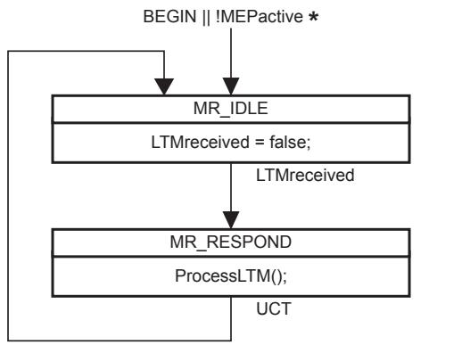
- MEPactive in a MEP; not present (always true) in an MHF
Figure 20-17—LTM Receiver state machine
20.49 LTR Transmitter procedure
The procedure local to the LTR Transmitter state machine is
a) xmitOldestLTR() (20.49.1).
20.49.1 xmitOldestLTR()
If and only if nPendingLTRs is nonzero, dequeues a single LTR and transmits it, and decrements nPendingLTRs by 1.
20.50 LTR Transmitter state machine
One instance of the LTR Transmitter state machine is instantiated by Bridge’s Linktrace Responder. The LTR Transmitter state machine implements the function specified by the state diagram in Figure 20-18, the variables in 20.46, and the procedures in 20.47.
This state machine implements the requirement of (20.3.2) to wait a random time interval after receiving an LTM before transmitting an LTR by means of a free running 1 s timer, the expiry of which triggers all LTR transmissions. This method avoids the need to create and manage a timer for every LTM received. Any other implementation that meets the requirements of 20.3.2 can be used in place of this state machine.
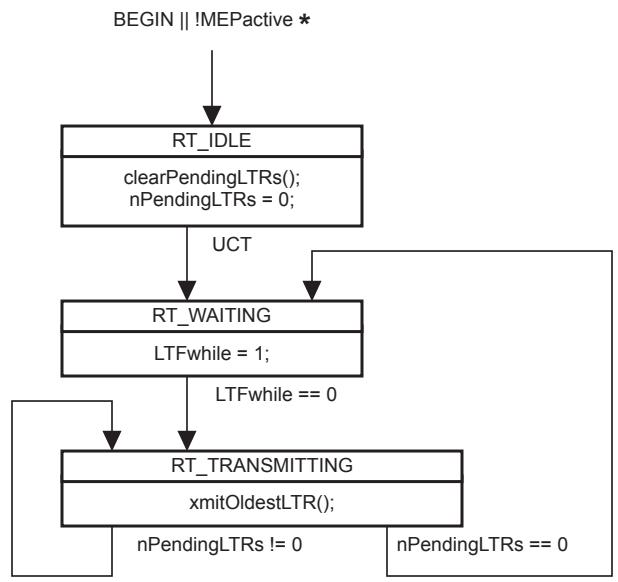
- MEPactive in a MEP; not present (always true) in an MHF
Figure 20-18—LTR Transmitter state machine
20.51 CFM PDU validation and versioning
The purpose of this subclause is to state specific goals to be achieved by CFM with respect to the relationship of this and future versions of this standard, and to define the procedures necessary to meet those goals.
20.51.1 Goals of CFM PDU versioning
The goals of CFM with respect to the relationship of this and future versions of this standard are to ensure that
a) Implementations of this standard will interoperate with implementations of future versions of this standard;
b) Implementers will be able to offer proprietary, nonstandard extensions to this standard with enhanced functionality; and
c) Conformant but extended implementations of this standard will not restrict the ability of future versions of this standard to extend the standard functionality.
20.51.2 PDU transmission
In order to ensure that future versions of CFM will be compatible with implementations of this standard, certain requirements are placed on transmitted CFM PDUs:
a) The fixed header fields shall be transmitted exactly as specified in this standard.
b) All bits defined as “reserved” in this standard, e.g., unused bits in the Flags field, shall be transmitted as 0.
c) Additional fields shall not be added to the fixed header specified in this standard.
d) Code points reserved in this standard, or in ITU-T Y.1731 (02/2008), e.g., additional values for the OpCode field in the fixed header (Table 21-4), the Type field in a TLV (Table 21-6), or the reserved values in Table 21-19 for the Maintenance Domain Name Format, shall not be transmitted in any CFM PDU.
e) Additional fields shall not be added to any TLV specified in this standard.
Organization-Specific TLVs can be defined by any organization possessing an OUI or a CID, and may be transmitted by an implementation conformant to this standard.
NOTE—The preceding is not an exhaustive list of the restrictions on the transmission of CFM PDUs; it is only a list of the specifications that are most important to future compatibility.
20.51.3 PDU validation
CFM PDUs that fail certain specified tests are discarded by MPs. This requirement is described here as a two-pass processing algorithm, first a Validation Pass, and then an Execution Pass. The Validation Pass is performed first. If and only if it succeeds, the Execution Pass is performed. This description does not preclude other algorithms. For example, an MP could process a CFM PDU in one pass, building a tentative list of changes to the affected state machines and databases, and commit the changes only after the processing has succeeded. However, the behavior of such an implementation shall be indistinguishable, in terms of externally observable behavior (i.e., Management Objects and protocol packets) from the two-pass algorithm described in this subclause.
20.51.4 Validation pass
During the Validation pass, no changes are made to any CFM database other than the updating of certain management counter variables. No protocol state machines are affected, and no changes are made to any CFM PDUs that can be transmitted by the receiving MP. The description of the Validation pass is split into three parts:
a) Operations required of an MP Level Demultiplexer (20.51.4.1);
b) Operations required of all MP components when performing the Validation pass (20.51.4.2); and
c) Operations that are required of some MP components, and optional for others (20.51.4.3).
20.51.4.1 Validation pass operations required of an MP Level Demultiplexer
If the following test fails, the receiving MP Level Demultiplexer (19.2.6) shall consider the CFM PDU invalid and discard it:
a) The length of the mac_service_data_unit is long enough to contain a complete MD Level field.
20.51.4.2 Validation pass operations required of MP components
All bits declared “reserved” in this standard, e.g., unused bits in the Flags field, shall be ignored by the receiving MP.
The receiving MP processes the CFM PDU in accordance with the numerically lower of 1) the Version field in the CFM PDU and 2) the highest Version number known to the receiving implementation. That is, a Version 1 implementation receiving a Version 0 CFM PDU processes it according to Version 0 of this standard, and it processes a Version 2 CFM PDU according to Version 1. The IEEE 802.1 Working Group places the imposition on future versions of this standard that all earlier version implementations can process their CFM PDU properly.
As an example of the use of this rule, if a new Flags field bit is defined in Versions 2 and 3, then a Version 3 implementation receiving a Version 1 CFM PDU will ignore that bit, even though the bit is defined in both Version 2 and Version 3, and even though the bit is actually set.
<!-- merged from 802.1Q_2014_1201-1400.md -->
NOTE 1—One effect of this rule is that an implementation conformant to this Version of this standard, Version 0, ignores the Version field in a received CFM PDU.
The following criteria shall not be used by a CFM entity to validate a received CFM PDU:
a) The fixed header can be longer than the length specified by the version of this standard indicated by the CFM PDU’s Version field.
b) Bits can be set in reserved bits of the Flags field.
c) A TLV can have a Type field not specified by this standard.
d) A TLV’s Length field can be larger than the value (if any) specified in this standard. (This allows TLVs to be extended in future Versions.)
e) Either the First TLV Offset field, or the Length field of the last TLV, in the CFM PDU, can indicate a position for the first (next) TLV that coincides with the end of the mac_service_data_unit containing the CFM PDU. That is, the End TLV can be missing from the CFM PDU if the frame is longer than or equal to the minimum frame size for the media-dependent MAC sublayer.
NOTE 2—These latter criteria cannot be used by a CFM entity to validate a received CFM PDU. This helps to ensure that the CFM PDUs transmitted by future versions of this standard will be considered valid by implementations of the current version (0) of this standard. These criteria can, however, be used by test equipment in order to test the conformance of a system to this standard, e.g., to the rules in 20.51.2.
20.51.4.3 Validation pass operations required of some receiving MP components
The following Validation pass tests are required of some receiving MP components, and are optional for other MP components, as specified in other subclauses. If performed, and if any test fails, the receiving System shall consider the CFM PDU invalid and discard it.
a) The fixed header length, as determined by the First TLV Offset field (21.4.5), is not shorter than the length specified by the version selected according to 20.51.4.2.
b) The fixed-length header does not run over the end of the mac_service_data_unit.
c) A TLV Length field does not run over the end of the mac_service_data_unit.
d) A TLV Length field does not indicate a length that is shorter than the minimum length for that TLV as specified by the Version field of the CFM PDU.
e) Every header field and TLV in the CFM PDU meets the validity criteria specified in the header field and TLV definitions in Clause 21 (see the Validation Test headings in that clause).
20.51.5 Execution pass
The CFM PDU is processed in the Execution Pass. Changes to the CFM databases can be made, the state machines can change states, and the contents of future CFM PDUs can be affected by these changes. The receiving MP
a) Processes the CFM PDU in accordance with the numerically lower of 1) the Version field in the CFM PDU; and 2) the highest Version number known to the receiving implementation;
b) Processes only those fields in the fixed header portion of the CFM PDU that are defined in the selected Version of the standard, and ignores any extra octets in the fixed header, if the fixed header is longer than the length specified by the selected Version;
c) Ignores any TLV with a Type field not specified by the selected Version;
d) Does not process any part of the CFM PDU following the End TLV (the lack of an End TLV is not an error);
e) Ignores any octets following those specified by the selected Version, if any TLV’s Length field is larger than the value (if any) specified the selected Version; and
f) Ignores all bits undefined in this standard, e.g., unused bits in the Flags field.
Unlike the loss of ST BPDUs, the loss of CFM PDUs cannot completely disrupt the function of the network. Also, unlike other control protocols such as the IEEE 802.3 Slow Protocols, CFM PDUs can be presented at an arbitrarily high rate. Therefore, a Bridge shall ensure that receiving CFM PDUs on all Bridge Ports at the maximum possible rate supported by the MAC Services underlying those ports shall not significantly increase the probability of the failure of the Bridge to maintain loop-free forwarding paths in the bridged network. Rather, the Bridge’s CPU can be protected against excess CFM PDUs in a similar manner as for other potential Denial of Service attacks.
20.51.6 Future extensions
It is expected that future versions of this protocol will utilize the above versioning rules in order to extend the CFM PDU format in any number of ways, including perhaps
a) Adding new fields to the header by increasing the minimum size of the First TLV Offset field, and placing the new header fields after the First TLV Offset field in the Version 0 header.
b) Adding new TLVs and extending the lengths of existing TLVs with new fields.
c) Adding a new TLV, that is the first TLV to be processed, by renaming the First TLV Offset field to the “First Version 0 TLV Position,” adding a new “Version X Header Length” field following the fields in the Version 0 header, and inserting one or more Version X TLVs just ahead of the first required Version 0 TLV.
d) Adding new information, perhaps fixed-length information, that is required to follow the End TLV specified in Version 0.
Other methods for extending the CFM PDU format are certainly possible. It is therefore critical that Version 0 implementations adhere to the versioning requirements of this clause.
NOTE—The extension options discussed in this clause are reserved for use by future versions of this standard. Each one is a violation of 20.51.2, 20.51.4, and/or 20.51.5. The Organization-Specific TLV is the only available compliant extension to this standard.
20.52 PDU identification
A received CFM PDU is associated with a particular MP. Every data frame, including one carrying a CFM PDU, has some means, either explicit or implicit, by which that frame can be associated by the receiver with a particular service instance. In a Bridge that is not VLAN-aware, there is only one service instance. In a VLAN Bridge, the vlan_identifier (6.8) identifies the service instance. The means by which the appropriate receiving MP for processing a received CFM PDU is selected are
a) The direction (PHY side or MAC Relay Entity side) from which the CFM PDU was received;
b) The implicit or explicit association of the frame with a particular service instance (the vlan_identifier); and
c) The MD Level field in the CFM Header.
Once the frame containing the CFM PDU has been delivered to the appropriate entity within an MP, the destination_address can be used to decide whether the CFM PDU is to be processed or discarded, as specified in the description of each entity.
The MAID and/or Maintenance association Endpoint Identifier field is not used to identify the receiving MP. Thus, if the Individual MP address model (see J.6) is used by a particular Bridge, and each MP uses its Bridge Port’s individual MAC address, then the VID, MD Level, and flow direction uniquely identify the receiving MEP. If the Shared MP address model is used by a Bridge, so that Up MPs in the Bridge can share a MAC address, then the specific Bridge Port that is the target of an LBM can be genuinely ambiguous. This ambiguity allows the designer to trade the value of detailed information against cost of obtaining that information.
20.53 Use of transaction IDs and sequence numbers
Each CCM, LBM, and LTM has a field (21.6.3, 21.7.3, and 21.8.3) that is incremented for each PDU transmitted of each type, so that consecutively transmitted PDUs are in numerical order. The variables that control these fields are CCIsentCCMs (20.10.2, for CCM), nextLBMtransID (20.30.2, for LBM), and nextLTMtransID (20.41.1, for LTM).
In theory, every MEP in a Bridge has a CCIsentCCMs variable, a nextLBMtransID variable, and a nextLTMtransID variable, independently from every other MEP. Therefore, any number of MEPs in a single Bridge could be transmitting independent streams of LBMs and LTMs as long as they have different MAC addresses. (If they had the same MAC address, they could not tell each others’ LBRs and LTRs apart.)
In practice, there can be fewer instances of these variables and their corresponding state machines than one each per MEP. The managed objects in Clause 12, particularly the definitions of the MEP’s LBR counters [item y) in 12.14.7.1.3 and item z) in 12.14.7.1.3] and the responses permitted to the Transmit Loopback Messages command (12.14.7.3.3), are specified so that any number of MEP Loopback Initiator transmit state machines, from one to the number of MEPs, can be implemented. Each state machine can increment its own nextLBMtransID variable to determine the next transmitted Loopback Transaction Identifier field. Similarly, the allowed responses to the Transmit Linktrace Message command (12.14.7.4.3) provide the same latitude for the number of nextLTMtransID variables implemented. The resources for transmitting LTMs or streams of LBMs can then be used serially, rather than simultaneously, by different MEPs in the same Bridge.
On the other hand, every MEP that is incrementing its CCIsentCCMs variable has its own instance of that variable, and thus its own MEP Continuity Check Initiator state machine, because the Remote MEP state machines receiving those CCMs are tracking each MEP’s sequence of CCMs independently. A MEP can also transmit 0 in every CCM’s Sequence Number field.
21 Encoding of CFM PDUs
This clause specifies the method of encoding CFM PDUs. The specifications include the following:
a) Format used to encapsulate or decapsulate a CFM PDU in a frame (21.2);
b) Format of the Common CFM Header, used in all CFM PDUs (21.4);
c) Format used for all Type, Length, Value (TLV) information elements that can be included in CFM PDUs (21.5); and
d) Formats of the Continuity Check Message (CCM, 21.6), the Loopback Message and Loopback Reply (LBM and LBR, 21.7), the Linktrace Message (LTM, 21.8), Linktrace Reply (LTR, 21.9), Send Frame Message (SFM, 29.4.3), and the Reflected Frame Message (RFM, 29.4.2).
NOTE—Clause 18 introduces the principles of CFM operation and the network architectural concepts that support it. Clause 19 breaks down the CFM protocol entities into their components. Clause 20 specifies the protocols operated by the components of each MP. The use of CFM within systems and networks is further described in Clause 22.
21.1 Structure, representation, and encoding
All CFM PDUs shall contain an integral number of octets.
The octets in a CFM PDU are numbered starting from 1 and increasing in the order they are put into the MSDU that accompanies a request to or indication from the instance of the MAC Internal Sublayer Service (ISS or EISS) used by a CFM entity.
The bits in an octet are numbered from 1 to 8 in order of increasing bit significance, where 1 is the LSB in the octet.
Where octets and bits within a CFM PDU are represented using a diagram, octets shown higher on the page than subsequent octets and octets shown to the left of subsequent octets at the same height on the page are lower numbered; bits shown to the left of other bits within the same octet are higher numbered.
Where two or more consecutive octets are represented as hexadecimal values, lower numbered octet(s) are shown to the left and each octet following the first is preceded by a hyphen, e.g., 01-80-C2-00-00-00.
When consecutive octets are used to encode a binary number, the lower octet number has the more significant value. When consecutive bits within an octet are used to encode a binary number, the higher bit number has the most significant value. When bits within consecutive octets are used to encode a binary number, the lower octet number composes the more significant bits of the number. A flag is encoded as a single bit, and is set (True) if the bit takes the value 1, and clear (False) otherwise. The remaining bits within the octet can be used to encode other protocol fields.
21.2 CFM encapsulation
The means for identifying CFM PDUs depend on the medium. For media using a Length/Type field, e.g., IEEE 802.3 media, the identification consists of two octets containing the EtherType value shown (in hexadecimal notation) in Table 21-1. Media requiring an LLC encapsulation (e.g., IEEE 802.11) use the SNAP encoding shown (in hexadecimal notation) in Table 21-2.
Table 21-1—CFM PDU Encapsulation: Length/Type Media
<table><tr><td>1</td><td>2</td></tr><tr><td>89</td><td>02</td></tr></table>
Table 21-2—CFM PDU Encapsulation: LLC Media
<table><tr><td>1</td><td>2</td><td>3</td><td>4</td><td>5</td><td>6</td><td>7</td><td>8</td></tr><tr><td>AA</td><td>AA</td><td>03</td><td>00</td><td>00</td><td>00</td><td>89</td><td>02</td></tr></table>
21.3 CFM request and indication parameters
21.3.1 destination_address parameter
There are three classes of CFM PDUs in terms of the CFM entities to which they are addressed:
a) Those addressed to all MEPs in a service instance (CCM);
Those addressed to the set of MPs immediately adjacent to the transmitting MP, at a certain MD Level, in a service instance (LTM); and
c) Those addressed to a single, specific MP (LBM, LBR, LTR).
Frames carrying CFM PDUs belonging to two different MAs, but at the same MD Level, are distinguished from each other in the same manner as data frames are distinguished from each other in the corresponding service instances monitored by those MAs.
In a VLAN Bridge, it is the VID that distinguishes service instances. CCMs monitoring a service instance distinguished by its VID use the group MAC addresses listed in Table 8-15 as the destination_address. LTMs monitoring a VID-distinguished service instance use those shown in Table 8-16. All but the last three bits of the destination_address are fixed by the OpCode, either CCM or LTM. As shown in these two tables, the last three bits of the destination_address match the MD Level field of the CFM PDU Header. CFM PDUs belonging to MAs monitoring service instances distinguished by their I-SID use the same set of destination addresses as those belonging to MAs monitoring VLAN service instances. MAs monitoring TESIs are distinguished from MAs monitoring VLAN services by the vlan_identifier parameters and from each other by the 3-tuples <ESP-DA, ESP-SA, ESP-VID> of their ESPs. CFM PDUs belonging to PBB-TE MAs use the MAC address identified in the ESP-DA fields of their ESP identifiers.
21.3.2 source_address parameter
The individual MAC address of the MP transmitting the PDU. This is the MAC address of the transmitting MP. An MP’s MAC address is not necessarily unique; MPs configured on the same Bridge Port can share the same MAC address. The principles used to allocate Organization Unique Identifiers (OUIs) required that universally unique MAC addresses (those with the U/L bit = 0, see IEEE Std 802-2001, 9.2) not be used to create MP MAC addresses separately from a physical instance of an IEEE 802 MAC. See J.6 for a discussion of possible assignments of MAC addresses to MPs.
Validation Test: The source_address parameter contains an Individual, and not a Group, MAC address.
21.4 Common CFM Header
The format of a CFM PDU is shown in Table 21-3. A CFM PDU is identified by the encapsulation described in 21.2. Octets 1 through 4, including the MD Level, Version, OpCode, Flags, and First TLV Offset fields, constitute the Common CFM Header.
Table 21-3—Common CFM Header format
<table><tr><td>Field</td><td>Octet</td></tr><tr><td>MD Level</td><td>1 (high-order 3 bits)</td></tr><tr><td>Version</td><td>1 (low-order 5 bits)</td></tr><tr><td>OpCode</td><td>2</td></tr><tr><td>Flags</td><td>3</td></tr><tr><td>First TLV Offset</td><td>4</td></tr><tr><td>Varies with value of OpCode</td><td>5</td></tr><tr><td>End TLV (0)</td><td>First TLV Offset + 5</td></tr></table>
21.4.1 MD Level
(most significant 3 bits) Integer identifying the Maintenance Domain Level (MD Level) of the packet. Higher numbers correspond to higher MAs, those with the greatest physical reach, with the highest values for customers’ CFM packets. Lower numbers correspond to lower MAs, those with more limited physical reach, with the lowest values for single Bridges or physical links.
21.4.2 Version
(least significant 5 bits) The protocol version number, always 0. Ignored on receipt.
21.4.3 OpCode
(1 octet) The OpCode field specifies the format and meaning of the remainder of the CFM PDU. Certain values of the OpCode field are reserved for allocation by IEEE 802.1 and/or other organizations. The values for the various CFM PDU types are shown in Table 21-4. When assigning new OpCode values, pairs of CFM PDUs that operate in stimulus-response fashion, such as the LBM/LBR or the LTM/LTR pairs, will use even/ odd pairs of values such that the odd (numerically larger) of the two values is the stimulus, and the even (numerically smaller) the response.
Table 21-4—OpCode Field range assignments
<table><tr><td>CFM PDU or organization</td><td>OpCode range</td></tr><tr><td>Reserved for IEEE Std 802.1</td><td>0</td></tr><tr><td>Continuity Check Message (CCM)</td><td>1</td></tr><tr><td>Loopback Reply (LBR)</td><td>2</td></tr><tr><td>Loopback Message (LBM)</td><td>3</td></tr><tr><td>Linktrace Reply (LTR)</td><td>4</td></tr><tr><td>Linktrace Message (LTM)</td><td>5</td></tr><tr><td>Reflected Frame Message (RFM)</td><td>6</td></tr><tr><td>Send Frame Message (SFM)</td><td>7</td></tr><tr><td>Reserved for IEEE Std 802.1</td><td>8–31</td></tr><tr><td>Defined by ITU-T Y.1731 (02/2008)</td><td>32–63</td></tr><tr><td>Reserved for IEEE Std 802.1</td><td>64–255</td></tr></table>
21.4.4 Flags
(1 octet) The use of the Flags field is defined separately for each OpCode.
21.4.5 First TLV Offset
(1 octet) The offset, starting from the first octet following the First TLV Offset field, up to the first TLV in the CFM PDU. The value of the First TLV Offset field shall be transmitted as indicated in the specification for each of the OpCode field values, as follows (21.6.2, 21.7.2, 21.8.2, and 21.9.2).
21.5 TLV format
TLV stands for Type, Length, Value and denotes a method of encoding variable-length and/or optional information in a PDU. TLVs are not aligned to any particular word or octet boundary. TLVs follow each other with no padding between TLVs.
21.5.1 General format for CFM TLVs
The TLV format is shown in Table 21-5.
Table 21-5—TLV format
<table><tr><td>Field</td><td>Octet</td></tr><tr><td>Type</td><td>1</td></tr><tr><td>Length</td><td>2–3</td></tr><tr><td>(Value)</td><td>4</td></tr></table>
21.5.1.1 Type
(1 octet) Required. If 0, no Length or Value fields follow. If not 0, at least the Length field follows the Type field. The Type field is encoded as shown in Table 21-6.
Table 21-6—Type Field values
<table><tr><td>TLV or organization</td><td>Type field</td></tr><tr><td>End TLV</td><td>0</td></tr><tr><td>Sender ID TLV</td><td>1</td></tr><tr><td>Port Status TLV</td><td>2</td></tr><tr><td>Data TLV</td><td>3</td></tr><tr><td>Interface Status TLV</td><td>4</td></tr><tr><td>Reply Ingress TLV</td><td>5</td></tr><tr><td>Reply Egress TLV</td><td>6</td></tr><tr><td>LTM Egress Identifier TLV</td><td>7</td></tr><tr><td>LTR Egress Identifier TLV</td><td>8</td></tr><tr><td>PBB-TE MIP TLV</td><td>9</td></tr><tr><td>Data Part 1 TLV (29.3.3.2)</td><td>10</td></tr><tr><td>Data Part 2 TLV (29.3.3.2)</td><td>11</td></tr><tr><td>Truncated Data TLV (29.3.3.2)</td><td>12</td></tr><tr><td>Reserved for IEEE Std 802.1</td><td>13–30</td></tr><tr><td>Organization-Specific TLV</td><td>31</td></tr><tr><td>Defined by ITU-T Y.1731 (02/2008)</td><td>32–63</td></tr><tr><td>Reserved for IEEE Std 802.1</td><td>64–255</td></tr></table>
21.5.1.2 Length
(2 octets) Required if the Type field is not 0. Not present if the Type field is 0. The 16 bits of the Length field indicate the size, in octets, of the Value field. 0 in the Length field indicates that there is no Value field.
21.5.1.3 Value
(Length specified by the Length field) Optional. Not present if the Type field is 0 or if Length field is 0.
21.5.2 Organization-Specific TLV
Type = 31. Any organization can define TLVs for use in CFM. The format for such TLVs is shown in Table 21-7. The “OUI/CID” is an organizationally unique identifier or a Company ID, obtainable from IEEE.28 The Subtype is required, so that an additional OUI/CID will not be required if more Organization-Specific TLV are required by an owner of an OUI/CID.
This TLV category is provided to allow different organizations, such as IEEE 802.1, IEEE 802.3, ITU-T, as well as individual software and equipment vendors, to define TLVs that advertise information to remote entities attached to the same media, subject to the following restrictions:
a) Information transmitted in an Organization-Specific TLV shall not require the recipient to violate any requirement in this standard.
b) Information transmitted in one Organization-Specific TLV shall not be used to provide a means for sending messages that are larger than would fit within a single CFM PDU.
c) Organization-Specific TLVs shall conform to 20.51.
Table 21-7—Organization-Specific TLV format
<table><tr><td>Field</td><td>Octet</td></tr><tr><td>Type = 31</td><td>1</td></tr><tr><td>Length</td><td>2–3</td></tr><tr><td>OUI/CID</td><td>4–6</td></tr><tr><td>Subtype</td><td>7</td></tr><tr><td>Value (optional)</td><td>8 – (Length + 3)</td></tr></table>
21.5.3 Sender ID TLV
Type = 1. Identifies the Bridge on which the transmitting MP is configured and may also include a management address for that Bridge. The allowed values are those contained in the Chassis ID TLV and Management Address TLV in IEEE Std 802.1AB, modified to fit into a CFM TLV, as shown in Table 21-8. Whether the Sender ID TLV is transmitted, and what information is included in the TLV, are controlled by managed objects [item e) in 12.14.3.1.3, item d) in 12.14.5.1.3, item d) in 12.14.6.1.3].
Table 21-8—Sender ID TLV format
<table><tr><td>Field</td><td>Octet</td></tr><tr><td>Type = 1</td><td>1</td></tr><tr><td>Length</td><td>2–3</td></tr><tr><td>Chassis ID Length</td><td>4</td></tr><tr><td>Chassis ID Subtype</td><td>5</td></tr><tr><td>Chassis ID</td><td>6 – (Chassis ID Length + 5)</td></tr><tr><td>Management Address Domain Length</td><td>(Chassis ID Length + 6)</td></tr><tr><td>Management Address Domain</td><td>(Chassis ID Length + 7) –(Chassis ID Length + Management Address Domain Length + 6)</td></tr><tr><td>Management Address Length</td><td>(Chassis ID Length + Management Address Domain Length + 7)</td></tr><tr><td>Management Address</td><td>(Chassis ID Length + Management Address Domain Length + 8) –(Length + 3)</td></tr></table>
Validation Test: The Length field is large enough to contain all of the fields indicated as being present by the Chassis ID Length, Management Address Domain Length, and/or Management Address Length fields.
21.5.3.1 Chassis ID Length
(1 octet) The length, in octets, of the Chassis ID field. 0 if no Chassis ID is specified. Always present.
Validation Test: The Chassis ID Length field either is 0, or is less than (TLV Length field value – 1).
21.5.3.2 Chassis ID Subtype
(1 octet) Identifies the format of the Chassis ID field. Specified by IEEE Std 802.1AB-2005, 9.5.2.2. Not present if the Chassis ID Length field contains 0.
21.5.3.3 Chassis ID
(Length specified by the Chassis ID Length field) Identifies the chassis. Specified by IEEE Std 802.1AB. Not present if the Chassis ID Length field contains 0.
21.5.3.4 Management Address Domain Length
(1 octet) The Management Address Domain Length field contains the length, in octets, of the Management Address Domain field. If 0, or if the TLV’s Length field indicates that the Management Address Domain Length field is not present, then the Management Address Domain, Management Address Length, and Management Address fields are not present.
21.5.3.5 Management Address Domain
(Length specified by the Management Address Domain Length field) The Management Address Domain field specifies the format and type of the contents of the Management Address field, as well as a management mechanism. The format of the Management Address Domain field shall be that of an Object Identifier (OID), as specified by ITU-T X.690 (2002), 8.19. The OID references a TDomain (IETF RFC 2579). Standard values that are useful for the Management Address Domain field include, but are not limited to,
transportDomainUdpIpv4, indicating Simple Network Management Protocol (SNMP) over User Datagram Protocol (UDP) over IPv4 (IETF RFC 3419);
transportDomainUdpIpv6, indicating SNMP over UDP over IPv6 (IETF RFC 3419); and
snmpIeee802Domain, indicating SNMP over the MAC Service (IETF RFC 4789).
This field is not present if the Management Address Domain Length field is not present or contains a 0.
21.5.3.6 Management Address Length
(1 octet) The length, in octets, of the Management Address field. This field is not present if the Management Address Domain Length field is not present or contains a 0.
21.5.3.7 Management Address
(Length specified by the Management Address Length field) Identifies a TransportDomain (IETF RFC 3419, IETF RFC 4789) through which the Bridge in which the transmitting MP is configured can be managed. The format of the Management Address field is specified by the MIB module defining the TransportDomain. This field is not present if the Management Address Domain Length field is not present or contains a 0, or if the Management Address Length field is not present or contains a 0.
NOTE—The contents of the Management Address Domain and Management Address are defined in terms of MIB modules. Therefore, a published MIB module is required in order to define a specific valued that can be used in the Management Address Domain field. However, the use of Management Address Domain field by a system does not require that the system be manageable via SNMP; the published MIB module could define, for example, a TransportDomain for a proprietary Command Line Interpreter over ITU-T X.25 [B44].
21.5.4 Port Status TLV
Type = 2. The Port Status TLV indicates the ability of the Bridge Port on which the transmitting MEP resides to pass ordinary data, regardless of the status of the MAC. The value of this TLV is driven by the MEP variable enableRmepDefect (20.9.2), as shown in Table 21-10. The format of this TLV is shown in Table 21-9. Any change in the Port Status TLV’s value triggers one extra transmission of that Bridge Port’s MEPs’ CCMs.
Table 21-9—Port Status TLV format
<table><tr><td>Field</td><td>Octet</td></tr><tr><td>Type = 2</td><td>1</td></tr><tr><td>Length</td><td>2-3</td></tr><tr><td>See Table 21-10</td><td>4</td></tr></table>
Table 21-10—Port Status TLV values
<table><tr><td>mnemonic</td><td>Ordinary data passing freely through the Port</td><td>value</td></tr><tr><td>psBlocked</td><td>No: enableRmepDefect = false</td><td>1</td></tr><tr><td>psUp</td><td>Yes: enableRmepDefect = true</td><td>2</td></tr></table>
Validation Test: The Port Status TLV contains one of the values listed in Table 21-10.
A MEP that is configured in a Bridge in a position that is not associated with a single value for the Port State and VID member set, e.g., a MEP in position 5 in Figure 22-9, on a Bridge running multiple spanning tree instances via MSTP, shall not transmit the Port Status TLV.
21.5.5 Interface Status TLV
Type = 4. The Interface Status TLV indicates the status of the interface on which the MEP transmitting the CCM is configured (which is not necessarily the interface on which it resides, see J.6), or the next lower interface in the IETF RFC 2863 IF-MIB. The format of this TLV is shown in Table 21-11. The enumerated values are shown in Table 21-12. These values correspond to the values for ifOperStatus in IETF RFC 2863.
Table 21-11—Interface Status TLV format
<table><tr><td>Field</td><td>Octet</td></tr><tr><td>Type = 4</td><td>1</td></tr><tr><td>Length</td><td>2–3</td></tr><tr><td>See Table 21-12</td><td>4</td></tr></table>
Validation Test: The Interface Status TLV field contains one of the values listed in Table 21-12.
Table 21-12— Interface Status TLV values
<table><tr><td>mnemonic</td><td>Interface Status (IETF RFC 2863 ifOperStatus)</td><td>value</td></tr><tr><td>isUp</td><td>up</td><td>1</td></tr><tr><td>isDown</td><td>down</td><td>2</td></tr><tr><td>isTesting</td><td>testing</td><td>3</td></tr><tr><td>isUnknown</td><td>unknown</td><td>4</td></tr><tr><td>isDormant</td><td>dormant</td><td>5</td></tr><tr><td>isNotPresent</td><td>notPresent</td><td>6</td></tr><tr><td>isLowerLayerDown</td><td>lowerLayerDown</td><td>7</td></tr></table>
21.5.6 Data TLV
Type = 3. Zero or more octets of arbitrary data. Serves several purposes, including reflected data frame in RFM, to be decapsulated data in SFM, the transmission of different frame sizes to test Maximum Service Data Unit Size capabilities and the testing for data-specific error dependencies. The Data TLV may be included in the LBM and the LBR, the RFM, and the SFM, but not in any other CFM PDU. The contents of the Data TLV shall not be examined or interpreted by the receiver of any CFM PDU except an LBR. The format of the Data TLV is shown in Table 21-13.
Table 21-13—Data TLV format
<table><tr><td>Field</td><td>Octet</td></tr><tr><td>Type = 3</td><td>1</td></tr><tr><td>Length</td><td>2–3</td></tr><tr><td>Data</td><td>4 – (Length + 3)</td></tr></table>
21.5.7 End TLV
Required. Type = 0. Length and Value fields are not present. The End TLV is the last TLV in the CFM PDU. (Lack of the End TLV does not invalidate a received CFM PDU, but certain cases where frames receive extra headers, e.g., MACsec or additional VLAN tags, can cause errors if it is not present.) The format of the End TLV is shown in Table 21-14.
Table 21-14—End TLV format
<table><tr><td>Field</td><td>Octet</td></tr><tr><td>Type = 0</td><td>1</td></tr></table>
21.6 CCM format
The format of the CCM is shown in Table 21-15. In order to limit the resources required to generate and receive CCMs, the following restrictions apply to the format of the CCM:
a) The Maintenance Domain Name and Short MA Name are encoded in a manner such that an MP can treat all of the fields from the Maintenance Domain Name Format field through the Short MA Name field as a unit when deciding whether a received CCM does or does not belong to the receiving MP’s MA. That is, the MP can perform a binary comparison of these fields in a received CCM to the fields it would transmit in its own CCMs. This means, for example, that two Maintenance Domain Names differing, e.g., only by trailing spaces or by upper/lower case substitutions, can be interpreted to denote different MAs.
b) The portion of the PDU allocated for the MAID is limited to 48 octets, in order to minimize the memory requirements of a hardware implementation of a MEP.
An MP shall be able to receive and process any valid CCM PDU that is 128 octets in length or less, starting with the MD Level/Version octet and including the End TLV. An MP shall not transmit a CCM PDU exceeding this length. An MP may discard as invalid any received CCM PDU that exceeds this length.
Table 21-15—CCM format
<table><tr><td>Field</td><td>Octet</td></tr><tr><td>Common CFM Header</td><td>1–4</td></tr><tr><td>Sequence Number</td><td>5–8</td></tr><tr><td>Maintenance association Endpoint Identifier</td><td>9–10</td></tr><tr><td>Maintenance Association Identifier</td><td>11–58</td></tr><tr><td>Defined by ITU-T Y.1731 (02/2008)</td><td>59–74</td></tr><tr><td>Reserved for definition in future versions of the protocola</td><td></td></tr><tr><td>Optional CCM TLVs</td><td>First TLV Offset + 5b</td></tr><tr><td>End TLV (0)</td><td>First TLV Offset + 5, if no Optional CCM TLVs are present</td></tr></table>
a This field has 0 length in this version 0 of CFM. It is shown in order to stress that additional information can be present in future versions of CFM, and that a version 0 receiver ignores its contents, if present.
b Octet 75 for transmitted CCMs.
21.6.1 Flags
(1 octet) The Flags field of the Common CFM Header is split into four parts for the CCM as follows:
a) RDI field (21.6.1.1);
b) Reserved field (21.6.1.2);
c) CCM Interval field (21.6.1.3); and
d) Traffic field (21.6.1.4).
21.6.1.1 RDI
The MSB of the Flags field is the RDI bit. This bit is set to 1 if the transmitting MEP’s presentRDI variable (20.9.6) is set, and 0 if not.
21.6.1.2 Reserved
The bits of the Flags field not including the RDI field, the Traffic field, and the CCM Interval field are set to 0 by the transmitting MP, and are not to be examined by the receiving MP [item b) in 20.51.2].
21.6.1.3 CCM Interval
The least significant 3 bits of the Flags field constitute the CCM Interval field. The CCM Interval field is encoded as specified in Table 21-16.
Table 21-16—CCM Interval field encoding
<table><tr><td>Transmission Interval</td><td>max. CCM Lifetime</td><td>min. CCM Lifetime</td><td>CCM Interval field</td></tr><tr><td colspan="3">invalid</td><td>0</td></tr><tr><td>3 1/3 ms(300 Hz)</td><td>11 2/3 ms</td><td>10 5/6 ms</td><td>1</td></tr><tr><td>10 ms</td><td>35 ms</td><td>32.5 ms</td><td>2</td></tr><tr><td>100 ms</td><td>350 ms</td><td>325 ms</td><td>3</td></tr><tr><td>1 s</td><td>3.5 s</td><td>3.25 s</td><td>4</td></tr><tr><td>10 s</td><td>35 s</td><td>32.5 s</td><td>5</td></tr><tr><td>1 min</td><td>3.5 min</td><td>3.25 min</td><td>6</td></tr><tr><td>10 min</td><td>35 min</td><td>32.5 min</td><td>7</td></tr></table>
NOTE—The maximum CCM Lifetime in Table 21-16 is equal to 3.5 times the CCM Interval. The minimum CCM Lifetime is the maximum CCM Lifetime minus 1/4 of the CCM Interval, the minimum required granularity of the timer variables CCIwhile, rMEPwhile, errorCCMwhile, and xconCCMwhile.
Validation Test: The CCM Interval field does not contain the value 0.
21.6.1.4 Traffic field
In the case of a PBB-TE MA or Infrastructure Segment MA, the second most significant bit of the Flags field is the Traffic bit. This bit if supported, is used to indicate the presence of backbone service instances in the monitored TESI or the assignment of TESIs in the monitored Infrastructure Segments. This bit is set to 1 if the transmitting MEP’s presentTraffic variable (20.9.8) is set in the case of a PBB-TE MEP or the transmitting MEP’s ISpresentTraffic variable (20.9.10) is set in the case of a Infrastructure Segment MEP, and 0 if not. This field is not examined if the receiving MPs are not PBB-TE or Infrastructure Segment MEPs supporting the traffic field.
21.6.2 First TLV Offset
(1 octet) The First TLV Offset field of the Common CFM Header in a CCM is transmitted as 70.
Validation Test: The First TLV Offset field of the Common CFM Header in a CCM contains a value greater than or equal to 70.
21.6.3 Sequence Number
(4 octets) A MEP either transmits a 0 in this field or copies to it the contents of the CCIsentCCMs variable (20.10.2).
21.6.4 Maintenance association Endpoint Identifier
(2 octets) Contains an integer value. This TLV specifies from which MEP the CCM was transmitted.
Validation Test: MEPID is in the range 1–8191.
21.6.5 Maintenance Association Identifier
(48 octets) This field contains the MAID of the transmitting MEP. It is divided into six subfields, plus, if necessary, a pad of octets contains 0 to fill out its fixed length. The subfields are
a) Maintenance Domain Name Format (21.6.5.1);
b) Maintenance Domain Name Length (21.6.5.2);
c) Maintenance Domain Name (21.6.5.3);
d) Short MA Name Format (21.6.5.4);
e) Short MA Name Length (21.6.5.5); and
f) Short MA Name (21.6.5.5).
The total length of these fields, including padding, if present, shall be exactly 48 octets. There are two possible formats of the Maintenance Association Identifier field, as shown in Table 21-17 and Table 21-18, depending on whether the Maintenance Domain Name is present.
Table 21-17—CCM Maintenance Association Identifier field format: Maintenance Domain present
<table><tr><td>Field</td><td>Octet</td></tr><tr><td>Maintenance Domain Name Format (not 1)</td><td>1</td></tr><tr><td>Maintenance Domain Name Length</td><td>2</td></tr><tr><td>Maintenance Domain Name</td><td><eq>3 - (mdnl^{a} + 2)</eq></td></tr><tr><td>Short MA Name Format</td><td><eq>(mdnl + 3)</eq></td></tr><tr><td>Short MA Name Length</td><td><eq>(mdnl + 4)</eq></td></tr><tr><td>Short MA Name</td><td><eq>(mdnl + 5) - (mdnl + smanl^{b} + 4)</eq></td></tr><tr><td>0 pad, if necessary</td><td><eq>(mdnl + smanl + 5) - 48</eq></td></tr></table>
a Maintenance Domain Name Length.
b Short MA Name Length.
Table 21-18—CCM Maintenance Association Identifier field format: Maintenance Domain not present
<table><tr><td>Field</td><td>Octet</td></tr><tr><td>Maintenance Domain Name Format (1)</td><td>1</td></tr><tr><td>Short MA Name Format</td><td>2</td></tr><tr><td>Short MA Name Length</td><td>3</td></tr><tr><td>Short MA Name</td><td><eq>4 - (smanl^{a} + 3)</eq></td></tr><tr><td>0 pad, if necessary</td><td><eq>(smanl + 4) - 48</eq></td></tr></table>
a Short MA Name Length.
21.6.5.1 Maintenance Domain Name Format
(1 octet) Specifies the format of the Maintenance Domain Name field. The Maintenance Domain Name Format is encoded according to Table 21-19.
Table 21-19—Maintenance Domain Name Format
<table><tr><td>Maintenance Domain Name Format field</td><td>Value</td></tr><tr><td>Reserved for IEEE Std 802.1</td><td>0</td></tr><tr><td>No Maintenance Domain Name present</td><td>1</td></tr><tr><td>Domain Name-based stringa</td><td>2</td></tr><tr><td>MAC address + 2-octet integer</td><td>3</td></tr><tr><td>Character stringb</td><td>4</td></tr><tr><td>Reserved for IEEE Std 802.1</td><td>5–31</td></tr><tr><td>Defined by ITU-T Y.1731 (02/2008)</td><td>32–63</td></tr><tr><td>Reserved for IEEE Std 802.1</td><td>64–255</td></tr></table>
a This is a string the terminal substring of which is an IETF RFC 1035 DNS Name, and the remainder of which is a text string, following the syntax of a DNS Name, denoting the identity of a particular Maintenance Domain.
b This is an IETF RFC 2579 DisplayString, with the exception that character codes 0-31 (decimal) are not used.
21.6.5.2 Maintenance Domain Name Length
(1 octet) Specifies the length in octets of the Maintenance Domain Name field. Not present if the Maintenance Domain Name Format field specifies “No Maintenance Domain Name present” (1).
Validation Test: The Maintenance Domain Name Length in a CCM, if present, is greater than or equal to 1, and less than or equal to 43.
21.6.5.3 Maintenance Domain Name
(Length specified by the Maintenance Domain Name Length field) Contains the Maintenance Domain Name, in the format specified by the Maintenance Domain Name Format field. Not present if the Maintenance Domain Name Format field specifies “No Maintenance Domain Name present” (1).
21.6.5.4 Short MA Name Format
(1 octet) Specifies the format of the Short MA Name field. The Short MA Name Format is encoded according to Table 21-20.
Table 21-20—Short MA Name Format
<table><tr><td>Short MA Name Format Field</td><td>Value</td></tr><tr><td>Reserved for IEEE Std 802.1</td><td>0</td></tr><tr><td>Primary VID</td><td>1</td></tr><tr><td>Character stringa</td><td>2</td></tr><tr><td>2-octet integer</td><td>3</td></tr><tr><td>IETF RFC 2685 VPN ID</td><td>4</td></tr><tr><td>Reserved for IEEE Std 802.1</td><td>5–31</td></tr><tr><td>ICC-based format as specified in ITU-T Y.1731 (02/2008)</td><td>32</td></tr><tr><td>Defined by ITU-T Y.1731</td><td>33–63</td></tr><tr><td>Reserved for IEEE Std 802.1</td><td>64–255</td></tr></table>
a This is an IETF RFC 2579 DisplayString, with the exception that character codes 0-31 (decimal) are not used.
21.6.5.5 Short MA Name Length
(1 octet) Specifies the length in octets of the Short MA Name field.
Validation Test: The Short MA Name Length in a CCM contains a value greater than or equal to 1.
Validation Test: The Short MA Name Length in a CCM does not indicate that the Short MA Name runs over the 48-octet limit for the MAID.
21.6.5.6 Short MA Name
(Length specified by the Short MA Name Length field) Contains the Short MA Name, in the format specified by the Short MA Name Format field.
21.6.6 Defined by ITU-T Y.1731 (02/2008)
(16 octets) The use of this field is defined by ITU-T Y.1731. A value of 0 should be transmitted in this field.
21.6.7 Optional CCM TLVs
The following TLVs should be included, as allowed by their specifications, in every CCM transmitted:
a) Sender ID TLV (21.5.3);
b) Port Status TLV (21.5.4); and
c) Interface Status TLV (21.5.5).
The following TLV may be included in any CCM transmitted:
d) Organization-Specific TLV (21.5.2).
The Optional CCM TLVs in this subclause may be placed in any order by the MEP transmitting the CCM. The receiving MP shall not depend upon any particular ordering of the Optional CCM TLVs in a CCM for its proper operation.
21.7 LBM and LBR formats
The format of the LBM and LBR is shown in Table 21-21.
Table 21-21—LBM and LBR formats
<table><tr><td>Field</td><td>Octet</td></tr><tr><td>Common CFM Header</td><td>1–4</td></tr><tr><td>Loopback Transaction Identifier</td><td>5–8</td></tr><tr><td>Reserved for definition in future versions of the protocola</td><td></td></tr><tr><td>Additional LBM/LBR TLVs</td><td>First TLV Offset + 5b</td></tr><tr><td>End TLV (0)</td><td>First TLV Offset + 5,if no Additional LBM/LBR TLVs are present</td></tr></table>
a This field has 0 length in this version 0 of CFM. It is shown in order to stress that additional information can be present in future versions of CFM, and that a version 0 receiver ignores its contents, if present.
b Octet 9 for transmitted LBMs.
21.7.1 Flags
(1 octet) In an LBM, the Flags field of the Common CFM Header is set to 0 by the transmitting MP, and is not examined by the receiving MP.
21.7.2 First TLV Offset
(1 octet) The First TLV Offset field of the Common CFM Header in an LBM or LBR is transmitted as 4.
Validation Test: The First TLV Offset field of the Common CFM Header in an LBM or LBR contains a value greater than or equal to 4.
21.7.3 Loopback Transaction Identifier
(4 octets) A MEP copies the contents of the nextLBMtransID variable (20.30.2) to this field.
21.7.4 Additional LBM/LBR TLVs
The following TLV shall be included in every LBM transmitted by a MEP to a MIP configured on a PBB-TE MA as specified in 21.7.5. The TLV will not be present in any other type of MA.
a) PBB-TE MIP TLV (21.7.5).
The following TLV should be included in every LBM transmitted:
b) Sender ID TLV (21.5.3).
The following TLV can be included by management action in any LBM transmitted:
c) Data TLV (21.5.6).
The following TLV may be included in any LBM transmitted:
d) Organization-Specific TLV (21.5.2).
The PBB-TE MIP TLV, if present, shall be placed first. The other Additional LBM/LBR TLVs may be placed in any order by the MEP transmitting the LBM.
21.7.5 PBB-TE MIP TLV
Type = 9. Used only in MAs monitoring PBB-TE services. It enables MIPs to selectively intercept LBMs that are targeting them. The PBB-TE MIP TLV is not used if the target address of the LBM or LTM is associated with any of the values in the ESP-DA field of the monitored MA’s ESPs; otherwise, it shall be present; The format of the PBB-TE MIP TLV is illustrated in Table 21-22.
Table 21-22—PBB-TE MIP TLV format
<table><tr><td>Field</td><td>Octet</td></tr><tr><td>Type = 9</td><td>1</td></tr><tr><td>Length</td><td>2–3</td></tr><tr><td>MIP MAC address</td><td>4–9</td></tr><tr><td>Reverse VID</td><td>10–11</td></tr><tr><td>Reverse MAC</td><td>12–17</td></tr></table>
Validation Test: The MIP MAC address field contains an individual MAC address.
Validation Test: The Reverse MAC field contains an Individual, or a group MAC address as specified in 21.7.5.3.
Validation Test: The Length field either is 8, indicating that no Reverse MAC field is present, or is 14, and thus contains the Reverse MAC field.
21.7.5.1 MIP MAC address
The MIP MAC address contains the destination MAC address for LBMs transmitted by the MEP [item b) in 12.14.7.3.2]. In the case of LTMs, this field in null.
21.7.5.2 Reverse VID
The Reverse VID field is used by the MIPs in order to set the vlan_identifier parameters on LBRs and LTRs. Its value is provided by the operator on the initiation of the LBM [item f) in 12.14.7.3.2] or the LTM [item e) in 12.14.7.4.2]. In the case of point-to-point TESIs, its value is the ESP-VID of the MA’s ESP that has the MEP’s MAC address in its ESP-DA field.
21.7.5.3 Reverse MAC
This Reverse MAC field refers to the ESP-SA of any of the point-to-point ESPs of the MA, if the LBM/LTM is initiated on a root PBB-TE MEP or to the ESP-DA of the point-to-multipoint ESP of the MA, if the LBM/ LTM is initiated on any of the leaf MEPs.
21.8 LTM format
The format of the LTM is shown in Table 21-23.
Table 21-23—LTM format
<table><tr><td>Field</td><td>Octet</td></tr><tr><td>Common CFM Header</td><td>1–4</td></tr><tr><td>LTM Transaction Identifier</td><td>5–8</td></tr><tr><td>LTM TTL</td><td>9</td></tr><tr><td>Original MAC Address</td><td>10–15</td></tr><tr><td>Target MAC Address</td><td>16–21</td></tr><tr><td>Reserved for definition in future versions of the protocola</td><td></td></tr><tr><td>Additional LTM TLVs</td><td>First TLV Offset + 5b</td></tr><tr><td>End TLV (0)</td><td>First TLV Offset + 5, if no Additional LTM TLVs are present</td></tr></table>
a This field has 0 length in this version 0 of CFM. It is shown in order to stress that additional information can be present in future versions of CFM and that a version 0 receiver ignores its contents, if present. b Octet 22 for transmitted LTMs.
21.8.1 Flags
(1 octet) In the LTM, the Flags field of the Common CFM Header specifies certain options as shown in Table 21-24.
Table 21-24—LTM Flags field
<table><tr><td>Mnemonic</td><td>Meaning</td><td>Bit</td></tr><tr><td>UseFDBonly</td><td>If set, indicates that only MAC addresses learned in a Bridge’s FDB, and not information saved in the MIP CCM Database, is to be used to determine the Egress Port.</td><td>8 (MSB)</td></tr><tr><td>Reserved</td><td>Transmitted as 0, and ignored by the receiver.</td><td>7–1</td></tr></table>
21.8.2 First TLV Offset
(1 octet) The First TLV Offset field of the Common CFM Header in an LTM is be transmitted as 17.
Validation Test: The First TLV Offset field of the Common CFM Header in an LTM contains a value greater than or equal to 17.
21.8.3 LTM Transaction Identifier
(4 octets) A MEP copies the contents of the nextLTMtransID variable (20.41.1) to this field.
21.8.4 LTM TTL
(1 octet) The number of hops remaining to this LTM. Decremented by 1 by each Linktrace Responder that handles the LTM. One less than this value is returned in the LTR. If 0 or 1 on input, the LTM is not transmitted to the next hop. If 0 on input, no LTR is returned. The value of the LTM TTL field in the LTM transmitted by the originating MEP is controlled by a managed object [item d) in 12.14.7.4.2]; the default value if none is specified is 64.
21.8.5 Original MAC Address
(6 octets) The MAC address of the MEP that originated the LTM. This can be different from the source MAC address of an LTM because each MIP along the path puts its own MAC address in the source MAC address field, while retaining the Original MAC Address Field.
Validation Test: The Original MAC Address field contains an Individual, and not a Group, MAC address.
21.8.6 Target MAC Address
(6 octets) Specifies an individual MAC address, the path to which the LTM is intended to trace. Any individual MAC address can be specified in this field. See also 20.3.1.
Validation Test: The Target MAC Address field contains an Individual, and not a Group, MAC address.
21.8.7 Additional LTM TLVs
The following TLV shall be included in every LTM by each MP originating or forwarding an LTM:
a) LTM Egress Identifier TLV (21.8.8).
The following TLVs may be included in an LTM by each MP originating or forwarding an LTM:
b) Sender ID TLV (21.5.3); and
c) Organization-Specific TLV(s) (21.5.2).
The following TLV shall be included in every LTM transmitted by a MEP configured on a PBB-TE MA. The TLV will not be present in any other type of MA.
d) PBB-TE MIP TLV (21.7.5).
The Additional LTM TLVs may be placed in any order by the MP transmitting the LTM.
21.8.8 LTM Egress Identifier TLV
Type = 7. Identifies the MEP Linktrace Initiator that is originating, or the Linktrace Responder that is forwarding, this LTM. The low-order (highest numbered) six octets contain an EUI-48 IEEE MAC address unique to the system in which the MEP Linktrace Initiator or Linktrace Responder resides. The high-order (lowest numbered) two octets contain an integer value sufficient to uniquely identify the transmitted LTM; a constant value (e.g., 0) is sufficient for this purpose, since a Bridge initiates or forwards only a single copy of an LTM. The format of the LTM Egress Identifier TLV is illustrated in Table 21-25.
NOTE—For most Bridges, the address of any MAC attached to the Bridge will suffice for the low-order six octets, and 0 for the high-order octets. In some situations, e.g., if multiple virtual Bridges utilizing emulated LANs are implemented in a single physical system, the high-order two octets can be used to differentiate among the transmitting entities.
Table 21-25—LTM Egress Identifier TLV format
<table><tr><td>Field</td><td>Octet</td></tr><tr><td>Type = 7</td><td>1</td></tr><tr><td>Length</td><td>2–3</td></tr><tr><td>Egress Identifier</td><td>4–11</td></tr></table>
21.9 LTR format
The format of the LTR is shown in Table 21-26.
Table 21-26—LTR format
<table><tr><td>Field</td><td>Octet</td></tr><tr><td>Common CFM Header</td><td>1–4</td></tr><tr><td>LTR Transaction Identifier</td><td>5–8</td></tr><tr><td>Reply TTL</td><td>9</td></tr><tr><td>Relay Action</td><td>10</td></tr><tr><td>Reserved for definition in future versions of the protocola</td><td></td></tr><tr><td>Additional LTR TLVs</td><td>First TLV Offset + 5b</td></tr><tr><td>End TLV (0)</td><td>First TLV Offset + 5,if no Additional LTR TLVs are present</td></tr></table>
a This field has 0 length in this version 0 of CFM. It is shown in order to stress that additional information can be present in future versions of CFM, and that a version 0 receiver ignores its contents, if present.
b Octet 11 for transmitted LTRs.
Validation Test: The Reply Ingress TLV (21.9.8), the Reply Egress TLV (21.9.9), or both, are present.
21.9.1 Flags
(1 octet) In the LTR, the Flags field of the Common CFM Header specifies certain options as shown in Table 21-27.
Table 21-27—LTR Flags field
<table><tr><td>Mnemonic</td><td>Meaning</td><td>Bit</td></tr><tr><td>UseFDBonly</td><td>Copied from LTM.</td><td>8 (MSB)</td></tr><tr><td>FwdYes</td><td>The LTM was (1) or was not (0) forwarded.</td><td>7</td></tr><tr><td>TerminalMEP</td><td>The MP reported in the Reply Egress TLV (Reply Ingress TLV, if the Reply Egress TLV is not present) is a MEP.</td><td>6</td></tr><tr><td>Reserved</td><td>Copied from LTM.</td><td>5–1</td></tr></table>
21.9.2 First TLV Offset
(1 octet) The First TLV Offset field of the Common CFM Header in an LTR is transmitted as 6.
Validation Test: The First TLV Offset field of the Common CFM Header in an LTR contains a value greater than or equal to 6.
21.9.3 LTR Transaction Identifier
(4 octets) The value from the LTM Transaction Identifier field in the LTM that triggered the transmission of this LTR.
21.9.4 Reply TTL
(1 octet) One less than the value from the LTM TTL field in the LTM that triggered the transmission of this LTR. If the LTM TTL field contained a 0, no LTR is transmitted.
21.9.5 Relay Action
(1 octet) Reports how the data frame targeted by the LTM would be passed through the MAC Relay Entity to the Egress Bridge Port, as shown in Table 21-28.
Table 21-28—Relay Action field values
<table><tr><td>Mnemonic</td><td>Relay action</td><td>Value</td></tr><tr><td>RlyHit</td><td>The LTM reached an MP whose MAC address matches the target MAC address.</td><td>1</td></tr><tr><td>RlyFDB</td><td>The Egress Port was determined by consulting the FDB [item a) in 20.47.1.2].</td><td>2</td></tr><tr><td>RlyMPDB</td><td>The Egress Port was determined by consulting the MIP CCM Database [item b) in 20.47.1.2].</td><td>3</td></tr></table>
Validation Test: The value in the Relay Action field is one of the values enumerated in 21.9.5.
21.9.6 Additional LTR TLVs
The following TLV shall be included in an LTR according to 20.3.2:
a) LTR Egress Identifier TLV (21.9.7).
One or both of the following TLVs shall be included in an LTR according to 20.3.2:
b) Reply Ingress TLV (21.9.8); or
c) Reply Egress TLV (21.9.9).
The following TLVs may be included in an LTR:
d) Sender ID TLV (21.5.3);
e) Organization-Specific TLV (21.5.2).
The Additional LTR TLVs may be placed in any order by the MP transmitting the LTR. The receiving MEP shall not depend upon any particular ordering of the Additional LTR TLVs in an LTR for its proper operation.
21.9.7 LTR Egress Identifier TLV
Type = 8. Identifies the source and destination of the LTM that triggered transmission of this LTR. The format of the LTR Egress Identifier TLV is illustrated in Table 21-29.
Table 21-29—LTR Egress Identifier TLV format
<table><tr><td>Field</td><td>Octet</td></tr><tr><td>Type = 8</td><td>1</td></tr><tr><td>Length</td><td>2–3</td></tr><tr><td>Last Egress Identifier</td><td>4–11</td></tr><tr><td>Next Egress Identifier</td><td>12–19</td></tr></table>
21.9.7.1 Last Egress Identifier
(8 octets) Identifies the MEP Linktrace Initiator that originated, or the Linktrace Responder that forwarded, the LTM to which this LTR is the response. This field takes the same value as the LTM Egress Identifier TLV of that LTM, or the value 0, if no LTM Egress Identifier TLV was present in that LTM.
21.9.7.2 Next Egress Identifier
(8 octets) Identifies the Linktrace Responder that transmitted this LTR, and can forward the LTM to the next hop. This field takes the same value as the LTM Egress Identifier TLV of the forwarded LTM, if any. If the FwdYes bit of the Flags field is false, the contents of this field are undefined, i.e., any value can be transmitted, and the field is ignored by the receiver.
21.9.8 Reply Ingress TLV
Type = 5. The format of the Reply Ingress TLV is shown in Table 21-30. The Reply Ingress TLV is transmitted if and only if the Bridge Port on which the LTM was received has an MP in the MA specified by the LTM.
Table 21-30—Reply Ingress TLV format
<table><tr><td>Field</td><td>Octet</td></tr><tr><td>Type = 5</td><td>1</td></tr><tr><td>Length</td><td>2–3</td></tr><tr><td>Ingress Action</td><td>4</td></tr><tr><td>Ingress MAC Address</td><td>5–10</td></tr><tr><td>Ingress Port ID Length</td><td>11</td></tr><tr><td>Ingress Port ID Subtype</td><td>12</td></tr><tr><td>Ingress Port ID</td><td>13 – (Length + 3)</td></tr></table>
Validation Test: The value in the Ingress Action field is one of the values enumerated in 21.9.8.1.
Validation Test: The Ingress MAC Address field contains an Individual, and not a Group, MAC address.
Validation Test: The Length field either is 7, indicating that no Ingress Port ID field is present, or is (9 + the Ingress Port ID Length field) or larger, and thus contains the Ingress Port ID field.
21.9.8.1 Ingress Action
(1 octet) Reports how the data frame targeted by the LTM would be received on the receiving MP, as shown in Table 21-31.
Table 21-31—Ingress Action field values
<table><tr><td>Mnemonic</td><td>Ingress action</td><td>Value</td></tr><tr><td>IngOK</td><td>The target data frame would be passed through to the MAC Relay Entity.</td><td>1</td></tr><tr><td>IngDown</td><td>The Bridge Port's MAC_Operational parameter is false.<eq>^a</eq></td><td>2</td></tr><tr><td>IngBlocked</td><td>The target data frame would not be forwarded if received on this Port due to active topology enforcement (8.6.1). (See Figure 22-1 to see how this is possible.)</td><td>3</td></tr><tr><td>IngVID</td><td>The ingress port is not in the member set of the LTM's VID, and ingress filtering is enabled, so the target data frame would be filtered by ingress filtering (8.6.2).</td><td>4</td></tr></table>
a This value could be returned, for example, by an operational Down MEP that has another Down MEP at a higher MD Level on the same Bridge Port that is causing the Bridge Port’s MAC_Operational parameter to be false.
21.9.8.2 Ingress MAC Address
(6 octets) The MAC address that can be used as the Destination MAC address of an LBM intended for the ingress MP.
21.9.8.3 Ingress Port ID Length
(1 octet) The length, in octets, of the Ingress Port ID field. Cannot be 0. If the Length field of the Reply Ingress TLV is less than $^ { 8 , }$ then the Ingress Port ID Length field, Ingress Port ID Subtype field, and Ingress Port ID field are not present.
21.9.8.4 Ingress Port ID Subtype
(1 octet) Identifies the format of the Ingress Port ID field. Format specified by IEEE Std 802.1AB-2005, 9.5.3.2. If the Length field of the Reply Ingress TLV is less than 8, then the Ingress Port ID Subtype field is not present.
21.9.8.5 Ingress Port ID
(Length specified by the Ingress Port ID Length field) Identifies the Ingress Port within the chassis identified in the Sender ID TLV, in the format specified by IEEE Std 802.1AB-2005, 9.5.3.3. If the Length field of the Reply Ingress TLV is less than 8, then the Ingress Port ID field is not present.
21.9.9 Reply Egress TLV
Type = 6. The format of the Reply Egress TLV is shown in Table 21-32. The Reply Egress TLV is included in the LTR if and only if the Bridge Port on which the LTM would be relayed could be identified, and is an MP in the MA specified by the LTM.
Validation Test: The value in the Egress Action field is one of the values enumerated in 21.9.9.1.
Table 21-32—Reply Egress TLV format
<table><tr><td>Field</td><td>Octet</td></tr><tr><td>Type = 6</td><td>1</td></tr><tr><td>Length</td><td>2–3</td></tr><tr><td>Egress Action</td><td>4</td></tr><tr><td>Egress MAC Address</td><td>5–10</td></tr><tr><td>Egress Port ID Length</td><td>11</td></tr><tr><td>Egress Port ID Subtype</td><td>12</td></tr><tr><td>Egress Port ID</td><td>13 – (Length + 3)</td></tr></table>
Validation Test: The Egress MAC Address field contains an Individual, and not a Group, MAC address.
Validation Test: The Length field either is 7, indicating that no Egress Port ID field is present, or is (9 + the Egress Port ID Length field) or larger, and thus contains the Egress Port ID field.
21.9.9.1 Egress Action
(1 octet) Reports how the data frame targeted by the LTM would be passed through Egress Bridge Port, as shown in Table 21-33.
Table 21-33—Egress Action field values
<table><tr><td>Mnemonic</td><td>Egress action</td><td>Value</td></tr><tr><td>EgrOK</td><td>The targeted data frame would be forwarded.</td><td>1</td></tr><tr><td>EgrDown</td><td>The Egress Port can be identified, but that Bridge Port's MAC_Operational parameter is false.</td><td>2</td></tr><tr><td>EgrBlocked</td><td>The Egress Port can be identified, but the data frame would not pass through the Egress Port due to active topology management (8.6.1), i.e., the Bridge Port is not in the Forwarding state.</td><td>3</td></tr><tr><td>EgrVID</td><td>The Egress Port can be identified, but the Bridge Port is not in the LTM's VID's member set, so would be filtered by egress filtering (8.6.4).</td><td>4</td></tr></table>
21.9.9.2 Egress MAC Address
(6 octets) The MAC address that can be used as the Destination MAC address of an LBM intended for the egress MP.
21.9.9.3 Egress Port ID Length
(1 octet) The length, in octets, of the Egress Port ID field. Cannot be 0. If the Length field of the Reply Egress TLV is less than 8, then the Egress Port ID Length field, Egress Port ID Subtype field, and Egress Port ID field are not present.
21.9.9.4 Egress Port ID Subtype
(1 octet) Identifies the format of the Egress Port ID field. Format specified by IEEE Std 802.1AB-2005, 9.5.3.2. If the Length field of the Reply Egress TLV is less than 8, then the Egress Port ID Subtype field is not present.
21.9.9.5 Egress Port ID
(Length specified by the Egress Port ID Length field) Identifies the Egress Port within the chassis identified in the Sender ID TLV. Format specified by IEEE Std 802.1AB-2005, 9.5.3.3. If the Length field of the Reply Egress TLV is less than 8, then the Egress Port ID field is not present.
22 CFM in systems
The relationships among MPs, and between the MPs and the other entities in a Bridge, are configurable. This configuration determines how CFM is used in a network and determines what parts of the Bridges and LANs comprising a network are protected by an MA. This clause provides both specifications and explanatory text to assist the implementor and system administrator to make efficient use of CFM. This clause
a) Specifies how the EISS Multiplex Entity (6.17) is used to support MPs for multiple MAs associated with service instances supported by EISS-SAPs (22.1);
b) Specifies the creation of MPs in a Bridge (22.2);
c) Suggests methods for the efficient assignment of MD Levels to Maintenance Domains (22.3);
d) Specifies the use of MPs in stations (22.4);
e) Clarifies issues related to the scaling of resources required to run CFM (22.5);
f) Shows how MPs can be placed in Provider Bridges (22.6);
g) Suggests methods for using CFM in the enterprise environment, as opposed to the provider environment (22.7); and
h) Provides guidance for the implementation of CFM in Bridges designed before the development of this standard (22.8).
NOTE—Clause 18 introduces the principles of CFM operation and the network architectural concepts that support it. Clause 19 breaks down the CFM protocol entities into their components. Clause 20 specifies the protocols operated by the components of each MP, and Clause 21 specifies the PDU formats used by those protocols.
22.1 CFM shims in Bridges
CFM is instantiated by configuring an MA, which maintains a single service instance. If multiple MAs, monitoring VLAN service instances, are configured on a single Bridge Port, the vlan_identifier parameter of the EISS and the MD Level in the CFM PDUs are used to multiplex CFM PDUs for the various MAs. Non-CFM data frames for these service instances are distinguished only by vlan_identifier: the particular service instance to which a non-CFM data frame belongs, if multiple service instances share the same VID, distinguished only by MD Level, is undetermined. MAs that monitor backbone or TESIs use I-SIDs or a combination of destination addresses, source addressees, and ESP-VIDs, respectively as service distinguishing parameters, instead of VIDs.
22.1.1 Preliminary positioning of MPs
Figure 22-1 illustrates how MPs are associated with particular VIDs or TESIs. The EISS Multiplex Entity (6.17) distributes frames across an array of ISS- or EISS-SAPs, each of which can have a “column” of MPs at different MD Levels and orientations (Up or Down). Several MEPs and MHFs are shown, distinguished by VID and MD Level in this manner.
NOTE—For MPs monitoring backbone service instances, it is the Backbone Service Instance Multiplex Entity (6.18) that is used to distinguish MPs by I-SIDs and associate MPs with particular backbone service instances as illustrated in Figure 26-2.
An MP that has its Passive SAP closer to the MAC Relay Entity than its Active SAP is called a “Down MEP” or “Down MHF,” because it points down, away from the MAC Relay Entity, in Figure 22-1. An MP that has its Passive SAP further away from the MAC Relay Entity than its Active SAP is called an “Up MEP” or “Up MHF.” The Bridge Port in Figure 22-1 is configured with five Up MEPs, three Up MHFs, three Down MHFs, and three Down MEPs. A single LOM is positioned below the per-VID Down MEPs.
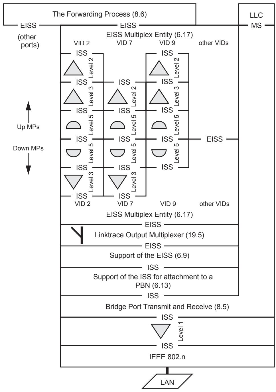
Figure 22-1—MEPs and MIPs distinguished by VID (incomplete picture)
Figure 22-1 illustrates a Down MEP, at MD Level 1, configured on the ISS below the Bridge Port connectivity entity. The service instance its MA protects encompasses all data frames passing through the Bridge Port, no matter what VID they are associated with.
22.1.2 CFM and the Forwarding Process
Figure 22-1 is incomplete, because it does not illustrate the relationship of CFM to the various components of the Forwarding Process (8.6). These components are illustrated in Figure 8-11. Readers can notice two facts about Figure 8-11:
a) The functions in Figure 8-11 can be divided into two groups. The first group, described in 8.6.1 through 8.6.5, consists of filtering functions that determine a set of potential transmission ports for each frame received at a reception port. The second group, described in 8.6.6 through 8.6.8, consists of queuing functions that control the transmission of the frame at each port in the resulting set of potential transmission ports.
b) The parameters passed from component to component in Figure 8-11 are exactly those of the EISS; therefore, each of the components in Figure 8-11 could be described as a shim.
From these facts, readers can reconstruct Figure 8-11 in a manner that is functionally identical, but is better suited to illustrate the relationship between CFM and the Forwarding Process. This reconstruction is shown in Figure 22-2.
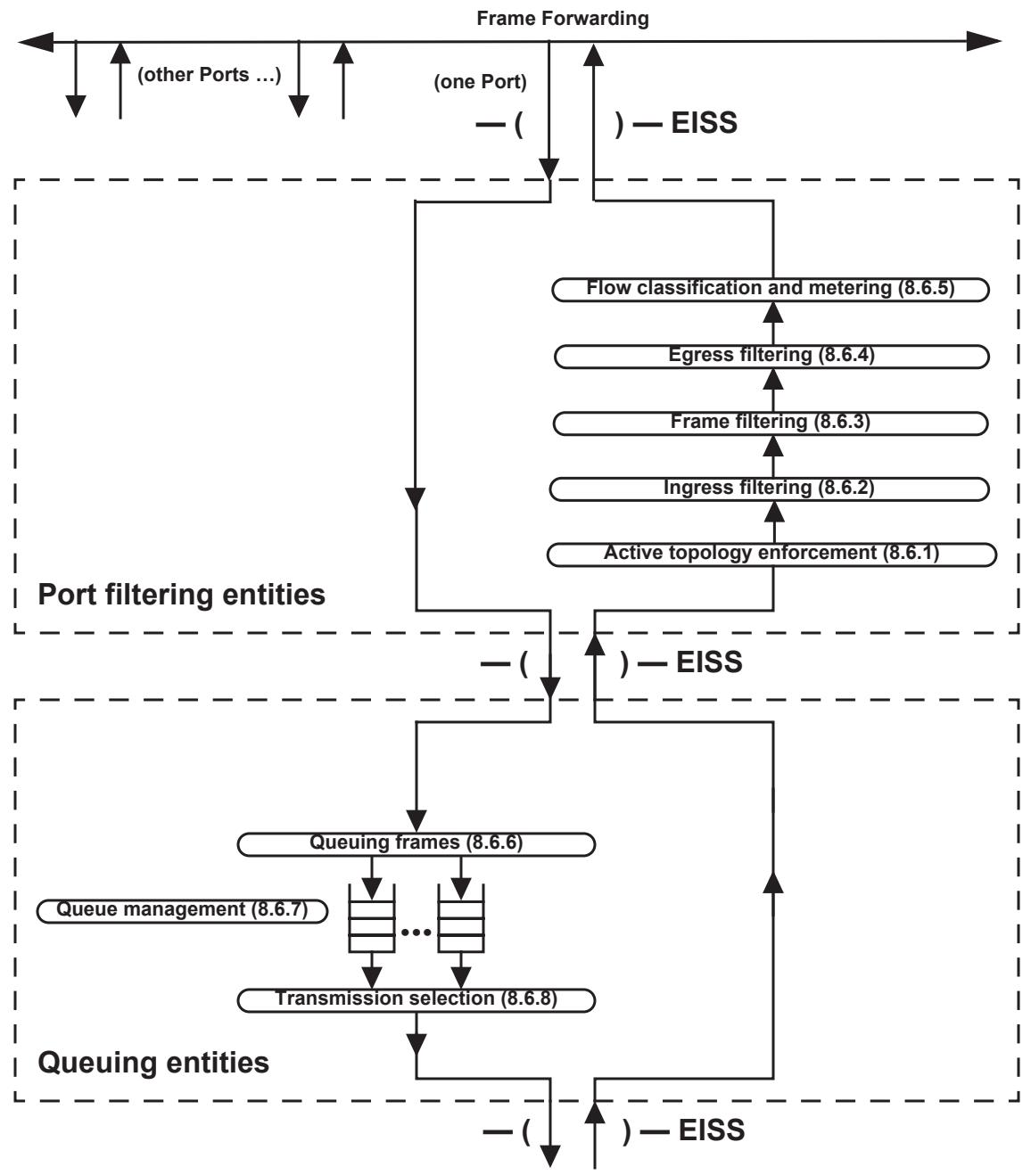
Figure 22-2—Alternate view of Forwarding process
22.1.3 Up/Down separation of MPs
An additional transformation to Figure 22-1 is required before the relationship between the Forwarding Process and CFM can be shown clearly. By adding a further pair of EISS Multiplex Entities between the Up MPs and the Down MPs in Figure 22-1, the entire set of Up MPs can be shown as a single shim, as can the entire set of Down MPs. This transformation is illustrated in Figure 22-3.
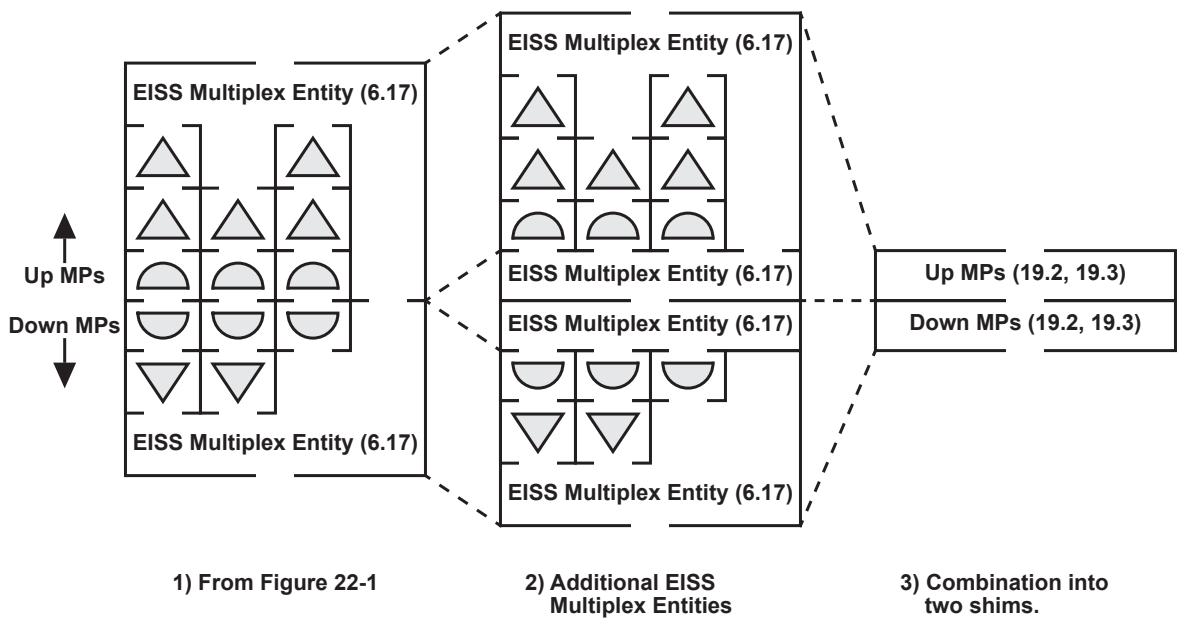
Figure 22-3—Combining per-VLAN MPs into two shims
Figure 22-4 combines Figure 22-1 with Figure 22-2, and shows the relationship of CFM to the various components of the Forwarding Process. MEPs and MHFs source and sink CFM PDUs. CFM PDUs are treated by the Port filtering entities in the same manner as ordinary data. Thus, the five Up MEPs of Figure 22-4 can transmit and receive CFM PDUs through the Bridge even when the Bridge Port is blocked. Similarly, the two Down MEPs in Figure 22-4 operate normally, transmitting CFM PDUs to and receiving them from the LAN, even if the Bridge Port is blocked. However, no frames, neither CFM PDUs nor ordinary data, can pass through the Port filtering entities when the VID to which those frames or CFM PDUs belong is filtered.
Also shown in Figure 22-4 are the positions of the DoSAPs and ISAPs introduced in Clause 18. The DoSAP provides access to a service instance (an instance of the MAC Service) and exists independently of any MA that might be created to protect it. The DoSAPs and ISAPs therefore can be associated with the specific inter-shim SAPs at the points indicated in Figure 22-4. The DoSAPs and ISAPs are attached to the Port filtering entities, because that is where the decisions are made on whether frames belonging to the service instance are or are not allowed to pass through the Bridge Port. 29 It does not matter to which side of the EISS Multiplex Entity one considers the DoSAPs and ISAPs to be attached. Except for the topmost Down MEP in each stack of Down MPs, the DoSAP is not coincident with the Passive SAP of the MEP protecting the DoSAP’s service instance; the DoSAP is separated from its MA by the MHFs and/or MEPs at higher MD Levels. Even for that topmost Down MEP, an MHF for a higher MD Level can separate that MEP from its DoSAP. This gap is illustrated in Figure 22-5 and Figure 22-6, where the service instance, DoSAP to DoSAP, is shown in gray, but the MEPs protecting that service are separated from the DoSAPs by MHFs belonging to a service instance at a higher MD Level.
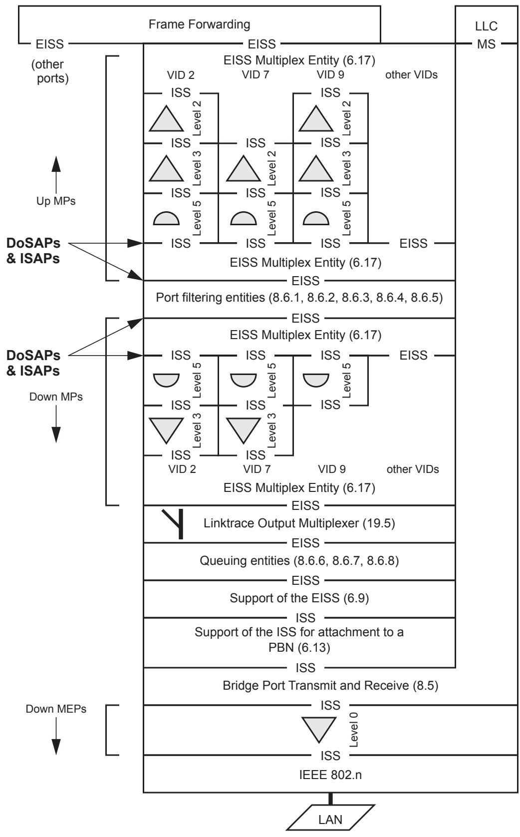
Figure 22-4—More complete picture of MP placement in a Bridge Port
In the “stack” of MPs on a single Bridge Port, the following rules apply:
a) All Up MEPs belonging to MAs that are attached to specific VIDs are placed above the Port filtering entities (8.6.1, 8.6.2, and 8.6.4). Separately for each VID, there can be from zero to eight Up MEPs, ordered by increasing MD Level, from the upper EISS toward Port filtering. In the case of PBB-TE MAs, more than one Up MEP can share the VID and MD Level.
b) For each MA there can be at most one MIP, consisting of an Up MHF just above, and a Down MHF just below, the Port filtering entities. Both MHFs are at the same MD Level, higher than the highest MEP on the same VID, if any. Backbone Service Instance MHFs use the Backbone Service Instance Multiplex Entity (6.18) and are placed as depicted in Figure 26-2.
c) Up to eight Down MEPs belonging to MAs that are attached to the same list of VIDs are placed between the Down MHF, if any, and the Queuing entities (8.6.6, 8.6.7, and 8.6.8). They are placed in order of decreasing MD Level, from the Port filtering entities to the Queuing entities, including any Down MHF.
d) No Down MEPs exist for PBB-TE MAs.
e) An LOM is positioned below the Down MPs belonging to MAs that are attached to specific VIDs to handle forwarded LTMs.
f) Up to eight Down MEPs, ordered from highest MD Level to lowest, belonging to MAs not attached to any specific VID, can be placed below Bridge Port connectivity (8.5.1). They are ordered by decreasing MD Level going away from the MAC Relay Entity (See also 22.1.8).
g) Up to 8 Up MEPs, ordered from highest MD Level to lowest, belonging to Backbone Service Instance MAs that are identified by the same I-SID, can be placed below the Bridge Port connectivity (8.5.1) using the Backbone Service Instance Multiplex Entity (6.18) as depicted in Figure 26-2. They are ordered by decreasing MD Level going away from the multiplexed SAP.
h) Up to 8 Down MEPs, ordered from highest MD Level to lowest, belonging to Backbone Service Instance MAs that are identified by the same I-SID, can be placed below the Bridge Port connectivity (8.5.1) using the Backbone Service Instance Multiplex Entity (6.18) as depicted in Figure 26-2. They are ordered by decreasing MD Level going away from the MAC Relay Entity.
i) All of the Down MEPs below Bridge Port connectivity have lower MD Levels than any Down MP attached to a VID that is emitted untagged by the Support of the EISS.
j) Any shim that introduces an EtherType tag insulates the MPs above and below it, removing any MD Level restriction between the separated groups of MPs.
A single Port on a Bridge could, in theory, have MHFs for multiple service instances at different MD Levels. However, that would require a vector of 4094 MD Level registers instead of one register to identify the CFM PDUs to be deflected to the Bridge’s Higher Layer Entities. This capability is optional.
22.1.4 Service instances over multiple Bridges
Figure 22-4 completes the sequence of expansions starting with Figure 18-5 and continuing with Figure 18-6 and Figure 18-7. In this sequence, Figure 22-4 illustrates Bridge Port b of Bridge 2 in Figure 18-5 through Figure 18-7. The service instances illustrated in those three figures all use VID 9 in Figure 22-4. The Up MEPs for VID 9 at MD Levels 3 and 2 are the Up MEPs protecting the provider MD Level and the operator MD Level service instances, respectively, and the pair of MHFs at MD Level 5 on VID 9 provide a customer MD Level MIP. Figure 22-4 also illustrates two other sets of service instances sharing the same Bridge Port using VIDs 2 and 7.
Additional views of service instances spanning two Bridges are shown in Figure 22-5 and Figure 22-6. Figure 22-5 shows a service instance protected by Up MPs, and Figure 22-6 shows a service instance protected by Down MPs.
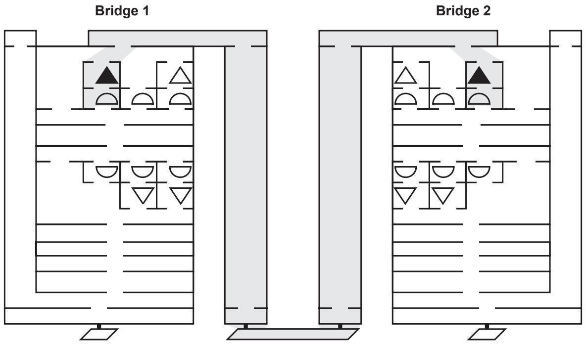
Figure 22-5—Service instance spanning two Bridges protected by Up MPs
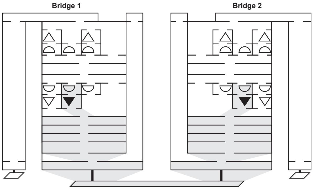
Figure 22-6—Service instance spanning two Bridges protected by Down MPs
22.1.5 Multiple VID service instances
A service instance can be implemented using multiple VIDs. It is always the case that the VLAN tag uniquely determines the VLAN service instance for a given frame. A VID-based MA or a PBB-TE MA with multiple VIDs does not require any more MIPs or MEPs than the corresponding MA with a single VID. All of the VIDs belonging to a given VID or TESI share the same MA. That is, one MAID is used for all CFM PDUs on the various VIDs in the same VID or TESI and Maintenance Domain. The choice of VID used to tag a given CFM PDU depends on the OpCode and the ESP, as specified in Clause 20.
22.1.6 Untagged CFM PDUs
A MEP placed anywhere below the Support of the EISS entity (6.9) or the Bridge Port connectivity entity (8.5.1) differs in three important respects from a MEP placed above the Support of the EISS entity:
a) The lower position would not have the Queuing entities available to it. For example, the reflection of a high-speed stream of LBMs (as LBRs) could seriously disrupt the flow of data frames, and thus bring into question the utility of the Queuing entities, CFM, or both.
b) A MEP in the lower position is necessarily VLAN untagged; the VLAN tagging functions are performed in the Support of the EISS entity.
c) A MEP in the lower position protects all data passing through the Bridge Port or if it is associated with a backbone service instance only data with this instance as specified in (26.8); it does not separately protect the different VLANs.
Point c) above does not mean that the lower position is the only one that can protect all of the traffic on a single link. MEPs placed above the Queuing entities can be associated with a VLAN whose VID is the PVID, for which this Bridge Port belongs to the untagged set. That VID can be statically configured in the member set to not be allowed to pass through the Frame filtering entity (8.6.3). MEPs so configured can then transmit and receive only untagged frames, and thus protect all of the data on the link. Their untagged CFM PDUs can be visible to complex “links” such as PBNs, even though the C-VLAN-tagged CFM PDUs are not visible inside the PBN.
The option to create MEPs below the Bridge Port connectivity entity for VID identified service instances cannot be omitted, however, because of considerations given in 22.1.8. This subclause also explains why only MEPs, and not MHFs, can be placed below the Bridge Port connectivity entity.
22.1.7 MPs and non-VLAN aware Bridges
The positioning of MPs in Bridges that are not VLAN aware (i.e., MAC Bridges) is illustrated in Figure 22-7. Because there are no VLANs, no EISS Multiplex Entity is needed. However, the Up MPs are still above the Port filtering entities, so the transformation introduced in 22.1.2 is still retained.
Down MPs can be placed either above or below the Queuing entities and Bridge Port connectivity in Figure 22-7; the difference between the two locations is that
a) In the upper location, frame queues are available to CFM, so that CFM frames and data frames can be scheduled appropriately for output; and
b) Placing a Down MEP in the lower location protects the LLC path used by the Higher Layer Entities, e.g., BPDUs, as well as the normal data forwarding path.
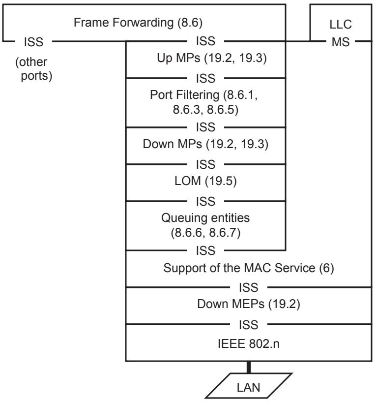
Figure 22-7—MP placement in a non-VLAN aware Bridge Port
22.1.8 MPs and other standards
The relationship of MPs and the shims defined by two other standards, IEEE Std 802.1AX (Link Aggregation) and IEEE Std 802.1AE-2006 [B6] (MAC Security), is illustrated in Figure 22-8. This figure shows Down MEPs positioned both above and below Link Aggregation and illustrates a number of points.
MPs could, in theory, be placed either above or below the MAC Security shim. No loss of data integrity beyond the protected link would be incurred by placing CFM below MAC Security; the only attacks that could be generated would be variants of a denial of service attack. However, there are several reasons for restricting MPs to positions above the MAC Security shim:
a) The denial of service attacks available by the introduction of bogus CFM PDUs have more potential for disrupting management operations, in more complex ways, than do attacks based on other unprotected protocols, namely those defined by IEEE Std 802.3. For example, bogus cross connect CCMs could be introduced, leading to undesirable interactions between different providers’ management systems.
b) MAC Security ensures that all data frames are legitimate, in the sense that they were last transmitted by a trusted device. Allowing the introduction of unprotected CFM PDUs violates the principle that data frames and CFM PDUs follow the same paths, distinguished only by the CFM protocol encapsulation.
c) Allowing the CFM and MAC Security shims to be interchanged by management operations could significantly complicate the implementation of a Bridge, with no commensurate benefit to the user.
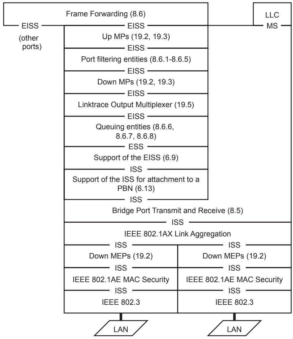
Figure 22-8—MP placement relative to other standards
As described in 22.1.6, placing an MP below the Queuing entities, whether above or below the Link Aggregation shim, is not desirable, as that MP is not able to use the Queuing entities. For this reason, it is preferable to use a Down MEP that is attached to a specific VID, and is thus above the Queuing entities, to protect the link.
When Link Aggregation is employed, Down MEPs attached to no VID can be useful for protecting the individual IEEE 802.3 LANs. The method used in Link Aggregation to select the outgoing IEEE 802.3 link is undefined. It is not necessarily possible for an MP above the Queuing entities to protect all of a Bridge Port’s data; CCM PDUs could take one IEEE 802.3 link, and data frames another. Therefore, provision is made in this standard for configuring Down MEPs in an MA attached to no VID below the Bridge Port connectivity entity, and below Link Aggregation, when employed. The following considerations are important when configuring Down MEPs:
d) It is best to disable the Bridge Port before issuing a high-speed stream of LBRs (relative to the physical link speed), either from or toward a Down MEP attached to no VID; otherwise, the Queuing entities might be unable to achieve any guarantees for throughput or latency.
e) The rate of CCMs generated by Down MEPs attached to VIDs should be taken into account when configuring the Queuing entities to achieve particular guarantees for throughput or latency.
f) If Link Aggregation is present, Down MEPs attached to no VID should be configured below Link Aggregation.
g) The creation of MHFs below Link Aggregation presents two problems that preclude it from this standard:
1) IEEE Std 802.3 provides no means for Link Aggregation to use a destination MAC address to direct a CFM PDU down the correct link to reach a particular MP at one or the other end of that link.
2) The utility of isolating the short segment between the Port filtering entities and the links being aggregated, which is completely internal to a Bridge, is very limited, especially considering the wide range of methods employed for implementing Link Aggregation.
22.1.9 CFM and IEEE 802.3-2012 Clause 57 OAM
The following differences between CFM and IEEE 802.3-2012 Clause 57 Operations, Administration, and Maintenance (OAM) are relevant to making a decision whether to employ one, the other, or both of these protocols.
a) IEEE 802.3 OAM has provision for a loopback mode in which all frames are returned to the sender. CFM does not.
NOTE—IEEE 802.3 OAM confines loopbacked frames to the individual IEEE 802.3 LAN, effectively disabling any attached Bridge Port. Use of simple frame loopback through a Bridged Network could be expected to seriously impact the operation of the network.
b) IEEE 802.3 OAM has provision for acquiring statistics from a remote interface. CFM does not.
c) IEEE 802.3 OAM has provision for generating error conditions when configured thresholds are exceeded for parameters such as the number of frames received with Cyclic Redundancy Check (CRC) errors. CFM does not.
d) IEEE 802.3 OAM has provision for organizations other than IEEE 802 to define both new TLVs and new operation codes using OUIs/CIDs. CFM allows only TLVs to be defined using OUIs/CIDs.
e) IEEE 802.3 OAM performs a continuity check once per second. CFM can be programmed to perform the continuity check over a wide range of intervals.
f) IEEE 802.3 OAM is defined only for IEEE 802.3 media. CFM can be used over any medium, or bridged network, that can carry IEEE 802 frames.
g) IEEE 802.3 OAM protects a single link. CFM can protect a single link or a network of bridged networks, over multiple nested ranges.
h) CFM can protect the connectivity of shared media. IEEE 802.3 OAM has no such capability.
i) CFM can perform in-band loopback tests at any rate up to the physical line rate, during normal operations. IEEE 802.3 OAM has no such capability.
j) CFM can perform Linktrace functions through a Bridged Network. IEEE 802.3 OAM has no such capability.
k) CFM can detect unintentional connectivity, as well as lack of connectivity. IEEE 802.3 OAM cannot.
22.2 Maintenance Entity creation
MPs are created using the managed objects described in 12.14. Before a MEP or MHF can be created, either an entry in the Default MD Level managed object, or the Maintenance Domain and MA to which the MEP or MHF belongs, are created. In this context, a Default MD Level managed object, Maintenance Domain, or an MA are strictly managed objects in a single Bridge. In order to realize the network-wide definitions of Maintenance Domains and MAs given in 18.1 and 18.2, the Bridges in a Maintenance Domain are configured with identical information in these managed objects. During transitional periods when this information is changing, Fault Alarms will likely be generated.
NOTE—The correct operation of CFM does not depend on the configuration restrictions in this subclause. Rather, violating these restrictions is likely to generate Fault Alarms that might or might not be erroneous. In other words, if no Fault Alarms are generated, then all monitored MAs have connectivity. If any Fault Alarm is generated, then either connectivity has been lost or the network is improperly configured. Determining which of these two is the cause of a Fault Alarm depends on the intentions of the operators and is therefore beyond the scope of this standard.
22.2.1 Creating Maintenance Domains and MAs
The operator creates either a Default MD Level managed object or a Maintenance Domain managed object in a Bridge for every Maintenance Domain whose CFM PDUs can pass through that Bridge and are to be processed. The operator can also create a MA managed object in a Bridge for some or all of the MAs whose CFM PDUs can pass through that Bridge and are to be processed. Whether a service instance can pass through a Bridge depends on
a) Enable Ingress Filtering per-Bridge Port parameter (8.6.2);
b) Static Filtering Entries (8.8.1)
c) Static VLAN Registration Entries (8.8.2);
d) PIP configuration parameters (6.10);
e) CBP configuration parameters (6.11);
f) Dynamic VLAN Registration Entries (8.8.5); and
g) Operation of MSTP (Clause 13), which in turn, can be affected by the state of the MAC_Operational parameters (IEEE Std 802.1AC) of the ISSs in the Bridge Port.
The first five of these methods are altered only by modifying managed objects and can therefore be considered static for the purposes of configuring CFM. The last two methods are dynamic, in that they depend not only on configuration, but on protocols that respond to network events, such as the addition or loss of a link or Bridge. For example, a VLAN can pass through a Bridge unless there is a Static VLAN Registration Entry prohibiting its VID from passing through every Bridge Port, and Ingress Filtering is enabled on every Bridge Port. If a Bridge’s Maintenance Domain requires only insignificant resources to support MHF configuration, then the most reliable network is one that assumes that all service instances will require MHFs at some MD Level higher than that of that Maintenance Domain.
22.2.2 Creating MEPs
There are four kinds of Maintenance Association managed objects: those that are attached to one or more specific VIDs in the Bridge, those that are attached to no VID, those that are attached to an I-SID, and those that are attached to a TESI or ECMP path.
Once the appropriate Maintenance Domain and MA have been created, a MEP can be created, modified, or deleted using the MA managed object defined in 12.14.6. MEPs are always created explicitly. MEP creation is controlled by creating a Maintenance association Endpoint managed object using the following parameters:
a) Whether the MA to which the MEP belongs is associated with specific VID(s), I-SID, TESI, or ECMP path, and if so, which parameters [item b) in 12.14.6.1.3], including a specification of the MA’s Primary VID [12.14.7.1.3:d];
b) Whether the MEP is a Down MEP (pointing away from the MAC Relay Entity), or an Up MEP, (pointing toward the MAC Relay Entity) [item c) in 12.14.6.3.2].
Given those two values in the MEP managed object, Table 22-1 shows where, in Figure 22-9, the MEP is created. In Figure 22-9, which shows a PNP or a CNP, the VID selects which of the MEP positions is selected for Table 22-1 column 3 values 1 and 4. Only one row of MEPs is shown in positions 1, 4, and 5, even though up to eight rows can exist at each of these points. Because the MEPs are always placed in order by MD Level, with the highest MD Level nearest the MHFs, at the center of each stack, there is thus no ambiguity. The third column, starting from the left, in the EISS Multiplex Entity depicted in Figure 22-9 corresponds to an ESP-VID or SPBM VID. Only MIPs can be placed in this column for a PNP. MEPs can be created on a CBP and PIP as shown in Figure 26-2.
Table 22-1—MEP creation
<table><tr><td>MA has VID [item b) in 12.14.6.1.3]</td><td>MEP direction [item c) in 12.14.7.1.3]</td><td>Position of MEP in Figure 22-9</td></tr><tr><td rowspan="2">Yes</td><td>Up</td><td>1</td></tr><tr><td>Down</td><td>4</td></tr><tr><td rowspan="2">No</td><td>Up</td><td>disallowed</td></tr><tr><td>Down</td><td>5</td></tr></table>
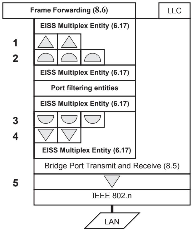
Figure 22-9—Creating MEPs and MIPs
If any MEPs are configured on an MA, then in any given Bridge, either all of those MEPs are Up MEPs or all of them are Down MEPs; a Bridge refuses to create an Up (Down) MEPs if a Down (Up) MEP already is configured in that MA in that Bridge. An MA can be configured with Up MEPs in one Bridge and Down MEPs in another Bridge or Station. Any given VID can be configured on any number of MAs (including zero) containing either Down MEPs or no MEPs at all, plus zero or one MA containing Up MEPs. No VID can be configured on more than one MA on which are configured Up MEPs.
These restrictions, along with the configuration errors in 22.2.4, enable MEPs to be configured so that they bound an MA, no matter what action is taken by the spanning tree protocols within a Maintenance Domain.
22.2.3 Creating MIPs
Managed objects control the creation of MIPs, but indirectly, rather than explicitly, as for MEPs. Every MA defined in a Bridge can cause the management entity to create MIPs on every Bridge Port. On each Bridge Port, the following conditions trigger the management entity to reevaluate the creation of MIPs for a given VID (or list of VIDs) or I-SID x on that port:
a) The Bridge is initialized;
b) A MEP is created or deleted on VID(s) or I-SID x on that Bridge Port;
c) An Up MEP is created or deleted on VID(s) x, which is (are) not allocated to a TESI, on any Bridge Port or an Up MEP is created or deleted on I-SID x;
d) A change occurs in whether VID(s) or I-SID x can or cannot pass through the Bridge Port (22.2.1);
e) A change occurs in the Default MD Level managed object (12.14.3); or
f) A change occurs in a Maintenance Association managed object associated with VID(s) or I-SID x.
A MIP for VID-based service instances and TESIs is created by creating a pair of MHFs in positions 2 and 3 in Figure 22-9. MIPs associated with I-SIDs are created on the two sides of the multiplexed SAPs in the Backbone Service Instance Multiplex Entity as depicted in Figure 26-2. MAs that are associated with no VID are not considered in this subclause. For a given VID on a given Bridge Port, and in the absence of any of the configuration errors in 22.2.4, there are at most two MAs at each MD Level that can affect MIP creation, plus at most one entry in the Default MD Level managed object. If one or more of the configuration errors in 22.2.4 are present, this standard does not specify what MIPs the Bridge creates.
When required, the Maintenance Entity performs the MIP evaluation on each Bridge Port for each VID. For each Bridge Port p and service identifier x, which can be a list of VIDs, or an I-SID, the Maintenance Entity creates a list of active MD Levels. This list contains:
g) MD Level of each of the MAs (if any) that monitors service x and has a MEP configured on Bridge Port p;
h) MD Level of each of the MAs (if any) that monitors a service x, and has at least one Up MEP configured on some Bridge Port in this Bridge other than Bridge Port $p \mathrm { ; }$
i) MD Level of each of the MAs (if any) that monitors service x and has no MEPs configured on any Bridge Port in this Bridge; and
j) MD Level of the entry in the Default MD Level managed object (12.14.3) for service x.
Exactly one MD Level d in this active list is eligible for MIP creation. It is the lowest MD Level in the list of active MD Levels such that there is no MEP configured on Bridge Port p and service x at MD Level d or at any higher MD Level. This is the lowest MD Level in the list, if there is no such MEP configured. The Maintenance Entity then uses Table 22-2 to determine whether the MIP is to be created.
Table 22-2—MIP creation
<table><tr><td>Enumeration [item d) in 12.14.3.1.3, item c) in 12.14.5.1.3, or item c) in 12.14.6.1.3]</td><td>A MEP is configured on Bridge Port p</td><td>MIP created</td></tr><tr><td>defMHFnone:</td><td>—</td><td>No</td></tr><tr><td rowspan="2">defMHFexplicit</td><td>False</td><td>No</td></tr><tr><td>True</td><td>Yes</td></tr><tr><td>defMHFdefault</td><td>—</td><td>Yes</td></tr></table>
The enumeration controlling whether the MIP is created is taken from
k) The Maintenance Association managed object [item c) in 12.14.6.1.3] for the MA that monitors service x, and has at least one Up MEP configured on some Bridge Port in the Bridge [see item h)];
l) That MA’s Maintenance Domain managed object [item c) in 12.14.5.1.3], if that MA exists, but its Maintenance Association managed object contains the value defMHFdefer; or
m) The Default MD Level managed object [item d) in 12.14.3.1.3] if no such MA exists [see item j)].
The enumerated values used in the managed objects item d) in 12.14.3.1.3, item c) in 12.14.5.1.3, and item c) in 12.14.6.1.3 to control the creation of a MIP for a service instance identified by the parameter x on a Bridge Port are
n) defMHFnone: No MHFs can be created for this VID(s) or I-SID (the default value).
o) defMHFdefault: MHFs can be created for this VID(s) or I-SID on any Bridge Port through which the VID(s) or I-SID can pass where:
1) There are no lower active MD levels; or
2) There is a MEP at the next lower active MD level on the port.
p) defMHFexplicit: MHFs can be created for this VID(s) or I-SID only on Bridge Ports through which this VID(s) or I-SID can pass, and only if there is a MEP at the next lower active MD level on the port.
q) defMHFdefer: In the Maintenance Association managed object [item c) in 12.14.6.1.3] only, the control of MHF creation is deferred to the corresponding variable in the enclosing Maintenance Domain [item c) in 12.14.5.1.3].
22.2.4 CFM configuration errors
While making the MIP creation evaluation described in 22.2.3, or whenever a MEP is created or deleted, the management entity can encounter errors in the configuration. Because of this, the Management entity maintains a Configuration Error List managed object (12.14.4) that lists, for every VID or I-SID, the Bridge Ports that have MIP configuration errors. Every time the MIP creation evaluation is performed or a MEP is created or deleted, this list is updated to reflect which Bridge Ports and VIDs are in error and which are not. A Bridge Port is placed in the list if and only if one of the following errors occurs:
a) CFMleak: MA x is associated with a specific VID list or I-SID, one or more of the VIDs or I-SID in MA x can pass through the Bridge Port, no Up MEP is configured for MA x on the Bridge Port, no Down MEP is configured on any Bridge Port for MA x, and some other MA y, at a higher MD Level than MA x, and associated with at least one of the VID(s) or the I-SID also in MA x, does have a MEP configured on the Bridge Port;
b) ConflictingVIDs: MA x is associated with a specific VID list or I-SID, an Up MEP is configured on MA x on the Bridge Port, and some other MA y, associated with at least one of the VID(s) or I-SID also in MA x, and at the same MD Level as MA x, also has an Up MEP configured on some Bridge Port;
c) ExcessiveLevels: The number of different MD Levels at which MIPs are to be created on this port exceeds the Bridge’s capabilities (see 22.3); or
d) OverlappedLevels: A MEP is created for one VID or I-SID at one MD Level, but a MEP is configured on another VID or I-SID at that MD Level or higher, exceeding the Bridge’s capabilities (see 22.3).
A Bridge uses detection of the ExcessiveLevels error to refuse an operation on a managed object and thus avoids adding Bridge Ports to the error lists. This is because this incremental operation is known to be the one that exceeds the capabilities of the Bridge. However, a Bridge uses only the detection of the ExcessiveLevels error to refuse an operation on a managed object. That is because the other errors can arise as a result of a management operation, e.g., the deletion of a Static VLAN Registration Entry, that has no knowledge of CFM and cannot report the error. Furthermore, the root cause of either error might not be the last MA to be configured and could be under the control of another administration. Therefore, management operations that trigger errors other than ExcessiveLevels are performed, not rejected. The lists of Bridge Ports in error are maintained (12.14.4), so that the system administrator(s) can agree on a course of action, outside this standard, to correct the problem.
22.3 MPs, Ports, and MD Level assignment
It is possible to configure MPs at different MD Levels for different VIDs on a single Bridge Port. However, this imposes upon an implementation the burden to be able to configure up to 8189 MD Levels for the VIDs on a Port, 4094 for MHFs and 4095 for MEPs, each requiring 3 bits of storage. An implementation may not support different MD Levels for MIPs on different VIDs on a single Port, hence the ExcessiveLevels and OverlappedLevels error responses (22.2.4). At least one MD Level shall be supported for each port in a Bridge, such that MIPs can operate at that MD Level, and all CFM PDUs below that MD Level are filtered or processed, according to the configuration of MEPs on the port.
In Figure 18-7, the left-most Maintenance Entity at the lowest MD Level (0) has one MEP in the customer’s equipment 1 and one in Provider Bridge 2. When Down MEPs are used in this manner to create a Maintenance Entity that interconnects two administrations, those administrations can agree upon a particular MD Level (and MAID and MEPIDs) to use. To enhance the chances for interoperability, the MD Level for Down MEPs should be the lowest not already in use by an existing MA, typically 0.
Assigning MD Levels with gaps between the levels used, as in Figure 18-7, can be wasteful of resources, especially MAC Address Registration Entries in the FDB. Minimizing the number of MD Levels, and concentrating the MD Levels used toward MD Level 0, minimizes the required resources, since CFM PDUs carrying higher MD Levels than those used in a Bridge are treated as ordinary multicasts by that Bridge. However, if one creates a Maintenance Domain at MD Level 0, and subsequently needs a level beneath that one, for example if a PBN is substituted for a physical connection, then the MD Level of the original Maintenance Domain might have to be changed. If there is another Maintenance Domain above the one at MD Level 0, that one would have to be changed, first, and so on. Similarly, if an existing Maintenance Domain at MD Level 3 is partitioned into several Domains, a new Maintenance Domain at MD Level 4 would be needed to ensure end-to-end connectivity across the extent of the old Maintenance Domain.
Such difficulties can be avoided in several ways:
a) The MD Levels of different Maintenance Domains can be insulated from each other by VLAN tags. Appropriate placement of the MEPs in Bridge Ports can ensure that the tags insulate the MD Levels, and that no reconfiguration will be necessary.
b) If it is expected that an additional MD Level will be needed because a physical link will likely become virtualized, MD Level 0 can be left vacant.
c) If it is expected that an additional MD Level will be needed because a Maintenance Domain will likely be partitioned, a gap can be left between that Maintenance Domain’s MD Level and the lowest MD Level offered to a customer of that Maintenance Domain.
See J.2 for a description of an MD Level assignment plan that can be used in the most general case.
22.4 Stations and CFM
Stations, as well as Bridges, can implement CFM. For the purposes of CFM, and for no other purposes, a Station is modeled as a Bridge, with the following exceptions:
a) This standard defines no entities above the layer of Down MPs in Figure 22-8. In particular, a Station has no Port filtering entities, Up MPs, or Forwarding Process. A CFM-capable Station is therefore a set of one or more disconnected Bridge Ports.
b) A Station shall not support the creation of MIPs or Up MEPs. Only Down MEPs can be implemented in a Station.
c) CFM PDUs not processed and not discarded by a MEP shall be ignored, and not processed, by the Station.
d) A Station shall create no entries in the Configuration Error List managed object (12.14.4) except for CFMleak errors.
22.5 Scalability of CFM
CFM can create a considerable load on the resources of a Bridge. Ideally, a Bridge has the capability to reflect LBMs as LBRs at line rate, so that the capacity and reliability of a network can be tested. The total load imposed by LBMs, LBRs, LTMs, and LTRs cannot be predicted, as these are all under the control of the system administrator, and any number of streams of these PDUs can be generated.
The load imposed by CCMs is more regular, so reasonable predictions of the load they impose can be made. Based on a figure of 109 octets as the minimum frame size, from the start of the destination MAC address of one frame to the start of the destination MAC address of the next frame,30 Table 22-3 shows the load that is imposed by CCM transmission and reception upon a Bridge Port with a single configured MEP, as a function of the CCM transmission interval, the number of MEPs in the MA, and the speed of the link. One row in the table shows the number of CCMs per second transmitted or received. The number in each of the other rows is the fraction of the total bandwidth required by those CCMs. Table 22-4 extends this calculation by multiplying all numbers by 1000, for the case where 1000 VIDs, each with a MEP, are configured on the Bridge Port, again with the specified transmission interval and average number of MEPs per MA.
Counting 4094 allowed VIDs in a VLAN tag, three kinds of MEPs, Up VID MEPs, Down VID MEPs, and Down no-VID MEPs, and eight MD Levels, a single Bridge Port with no Link Aggregation can, in theory, support 65 504 MEPs and 8188 MHFs.
Table 22-3—Bandwidth required for CCMs for 1 MA
<table><tr><td>Transmit interval</td><td colspan="2">3.3 ms</td><td colspan="2">10 ms</td><td colspan="2">1 s</td><td colspan="2">60 s</td></tr><tr><td>MEPs in each MA</td><td>10</td><td>2</td><td>10</td><td>2</td><td>10</td><td>2</td><td>10</td><td>2</td></tr><tr><td>CCM / s</td><td>3000</td><td>600</td><td>1000</td><td>200</td><td>10</td><td>2</td><td>0.167</td><td>0.033</td></tr><tr><td>10 Mb/s</td><td>26.160%</td><td>5.232%</td><td>8.720%</td><td>1.744%</td><td>0.087%</td><td>0.017%</td><td>0.001%</td><td>0.000%</td></tr><tr><td>100 Mb/s</td><td>2.616%</td><td>0.523%</td><td>0.872%</td><td>0.174%</td><td>0.009%</td><td>0.002%</td><td>0.000%</td><td>0.000%</td></tr><tr><td>1 Gb/s</td><td>0.262%</td><td>0.052%</td><td>0.087%</td><td>0.017%</td><td>0.001%</td><td>0.000%</td><td>0.000%</td><td>0.000%</td></tr><tr><td>10 Gb/s</td><td>0.026%</td><td>0.005%</td><td>0.009%</td><td>0.002%</td><td>0.000%</td><td>0.000%</td><td>0.000%</td><td>0.000%</td></tr><tr><td>100 Gb/s</td><td>0.003%</td><td>0.001%</td><td>0.001%</td><td>0.000%</td><td>0.000%</td><td>0.000%</td><td>0.000%</td><td>0.000%</td></tr></table>
Table 22-4—Bandwidth required for CCMs for 1000 MAs
<table><tr><td>Transmit interval</td><td colspan="2">3.3 ms</td><td colspan="2">10 ms</td><td colspan="2">1 s</td><td colspan="2">60 s</td></tr><tr><td>MEPs in each MA</td><td>10</td><td>2</td><td>10</td><td>2</td><td>10</td><td>2</td><td>10</td><td>2</td></tr><tr><td>CCM / s</td><td>3 000 000</td><td>600 000</td><td>1 000 000</td><td>200 000</td><td>10 000</td><td>2000</td><td>167</td><td>33</td></tr><tr><td>10 Mb/s</td><td>>100%</td><td>>100%</td><td>>100%</td><td>>100%</td><td>87.200%</td><td>17.440%</td><td>1.453%</td><td>0.291%</td></tr><tr><td>100 Mb/s</td><td>>100%</td><td>>100%</td><td>>100%</td><td>>100%</td><td>8.720%</td><td>1.744%</td><td>0.145%</td><td>0.029%</td></tr><tr><td>1 Gb/s</td><td>>100%</td><td>52.320%</td><td>87.200%</td><td>17.440%</td><td>0.872%</td><td>0.174%</td><td>0.015%</td><td>0.003%</td></tr><tr><td>10 Gb/s</td><td>26.160%</td><td>5.232%</td><td>8.720%</td><td>1.744%</td><td>0.087%</td><td>0.017%</td><td>0.001%</td><td>0.000%</td></tr><tr><td>100 Gb/s</td><td>2.616%</td><td>0.523%</td><td>0.872%</td><td>0.174%</td><td>0.009%</td><td>0.002%</td><td>0.000%</td><td>0.000%</td></tr></table>
22.6 CFM in Provider Bridges
The S-VLAN component of a Provider Bridge is, for the purposes of this standard, an example of a VLAN Bridge. Fortunately, the many combinations possible when configuring CFM on Customer Bridges and Provider Bridges, connected using Port-based, C-tagged, or Remote Customer Service Interfaces (RCSIs), can be simplified.
22.6.1 MPs and C-VLAN components
When a C-VLAN component is integrated into a Provider Edge Bridge to form a C-tagged service interface, there is little justification for making all possible CFM entities manageable. Subclause 15.4 describes a C-tagged service interface, illustrated in Figure 15-4. Figure 22-10 recasts Figure 15-4, illustrating the minimum set of CFM functions that a C-tagged service interface is required to support, if its Provider Bridge supports CFM. Almost all of the CFM components have been removed from the C-VLAN component. As a result, the transformations made in 22.1.2 and 22.1.3 are unnecessary, and the subclause references collapse to match those in Figure 15-4. The S-VLAN component contains almost the full suite of CFM entities. One set of shims has been moved from the CNP to the CEP, however.
The managed objects in 12.14 support the creation of up to eight MEPs below the Bridge Port Transmit and Receive process (8.5). These MEPs belong to MAs associated with no VID. A MEP in this position would be of little use in a CNP, since there is no need to pair it with a MEP in the PEP to protect an Internal LAN. However, a MEP attached to no VID in the CEP could be used to protect the LAN to the customer equipment.
In order to support protection of the CEP’s LAN, while maximizing interoperability, whenever (Down) MEPs are created (12.14.6.3) in an MA associated with no VID, a Provider Edge Bridge shall allow those MEPs to be created using the interface number [item d) in 12.14.6.3.2] for a CEP.
S-VLAN component
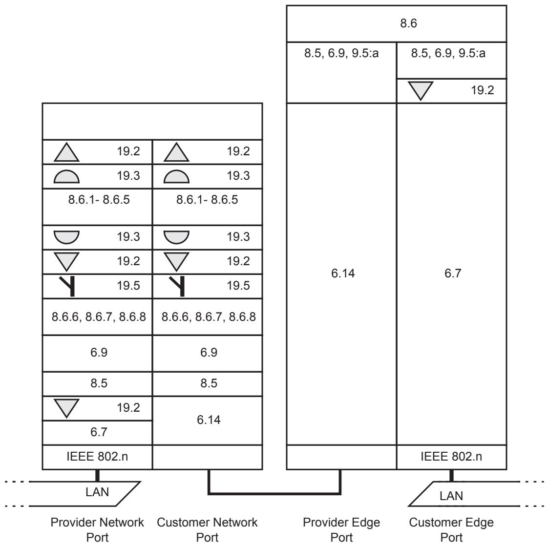
Figure 22-10—CFM in a Provider Edge Bridge C-tagged service interface
22.6.2 Maintenance C-VLAN on a Port-based service interface
Assume that a customer’s C-VLAN Bridge is attached to an S-VLAN Bridge as in Figure 22-4, and that the customer wants to pair a Down MEP in the C-VLAN Bridge with a similar Down MEP in the C-VLAN Bridge on the other side of the PBN, thus creating an MA to provide end-to-end protection of the service instance offered by the Provider. In order to obtain the advantage of inserting the CFM PDUs above the Queuing entities, the customer would not use MEPs below the Bridge Port Transmit and Receive process (8.5). The customer could create one MA for each C-VID. However, this would have drawbacks in that
a) The extra MAs beyond the first MA would provide very little protection on a Port-based service;
b) Each extra MA would add to the overhead of CFM PDUs; and
c) The C-tagged CFM PDUs would not be detected by any of the CFM entities in any Provider Bridge, so no MIPs would be present in the customer’s MAs.
If the customer, instead, creates an MA on only one C-VLAN, the Maintenance C-VLAN, and configures the two C-VLAN Bridges to pass the Maintenance C-VLAN across the PBN untagged, then
d) The service instance is protected; and
e) The provider can configure a MIP on the S-VLAN carrying the customer’s service instance that is visible in the customer’s MA.
22.6.3 Maintenance C-VLAN on a C-tagged service interface
Assume that a customer’s C-VLAN Bridge, illustrated by Figure 22-4 (less, of course, the box for “Support of the ISS for attachment to a PBN (6.13)”), is attached to a Provider Edge Bridge as in Figure 22-10. Assume that the customer has purchased several service instances, which have C-tagged service interfaces to other of the customer’s C-VLAN Bridges at several different locations. Let us further suppose that the customer wants to pair Down MEPs in the C-VLAN Bridge to create MAs to provide end-to-end protection of the service instances. In order to obtain the advantage of inserting the CFM PDUs above the Queuing entities, the customer would not use MEPs below the Bridge Port Transmit and Receive process (8.5). The customer could create one MA for each C-VID.
There would be more justification in creating an MA per C-VLAN than for the Port-based service instance described in 22.6.2. However, if the customer is reasonably confident that the provider will carry each C-VLAN in the correct S-VLAN, then the customer can create multiple Maintenance C-VLANs, one per provider service instance (S-VLAN), and thus one per PEP in the C-VLAN component. By configuring each of these PEPs to pass that one C-VLAN untagged to the corresponding CNP in the S-VLAN component, the CFM PDUs in that one customer MA are visible to the S-VLAN component. The provider can configure a MIP for that S-VID that is visible to the customer’s MA. The customer can have one MA protecting each service instance.
22.6.4 MPs and Port-mapping S-VLAN components
When a Port-mapping S-VLAN component is used to provide RCSIs there is little justification for making all possible CFM entities manageable. The other Provider Bridge components can provide the necessary MPs for service OAM. There is one MP that can only be provided by the Port-mapping S-VLAN component and that is the point below the Bridge Port Transmit and Receive process (8.5) on the RCAP. This MP can be used to protect the LAN to the neighboring PBN.
Figure 22-11 extends Figure 22-10, showing the minimum set of CFM entities required for a C-tagged RCSI, if the Provider Bridge supports CFM. The S-VLAN component and C-VLAN component support the same set of CFM entities as in Figure 22-10. The Port-mapping S-VLAN component that provides the RCSIs supports at least one more CFM entity, as shown, that can protect the LAN to the neighboring PBN.
Similarly, in the case of a Port-based RCSI or an internal PNP the required service CFM entities can be provided by the S-VLAN component. Thus the only CFM entity required from the Port-mapping S-VLAN component is the one shown in Figure 22-11 which is independent of the number and type of internal Ports provided.
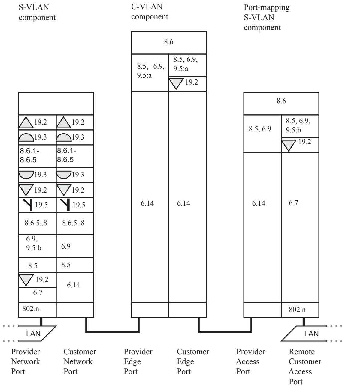
Figure 22-11—CFM in a Provider Edge Bridge C-tagged RCSI
22.7 Management Port MEPs and CFM in the enterprise environment
Figure 22-12 illustrates the placement of Management Port MEPs. It is similar to the CFM Port illustrated in Figure J-1. However, the Management Port MEPs are configured explicitly for the Management Port. They do not represent information for any other Bridge Port in their CFM PDUs. Therefore, there is only one MEP for each MA. Furthermore, there can be no MHFs configured on a Management Port, because there can be no MEP further along the path to terminate the MA.
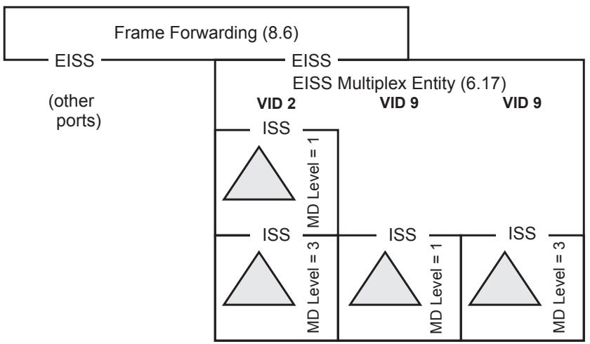
Figure 22-12—Up MEPs in a Management Port
NOTE—The fact that a CFM Port could be configured on a Management Port, and thus instantiate MHFs on the Management Port, does not contradict the preceding paragraph. Those MHFs are configured on a Bridge Port, and instantiated on the Management Port (CFM Port), not configured on the Management Port.
Although this standard uses the terminology of Provider Bridges and describes the functions of CFM in terms of Provider Bridges, it can be applied to any Bridge, whether a Provider Bridge, C-VLAN Bridge, or MAC Bridge. The normative definitions and functions specified by this standard do not depend on, for example, whether the VLAN tag used to associate frames with VLANs use the customer format or the provider format. Certainly, no business relationships are required to implement this standard.
Given that both the users and the providers of an enterprise network are, by definition, all members of the same company, the utility of CFM in the enterprise environment is less than in the provider/customer environment. The network administrator of an enterprise network can find a number of uses for CFM, however.
The default values for MEP and MIP configuration make CFM easy to configure for the typical enterprise network. Figure 22-13 illustrates two Bridge Ports, the Management Port, and one Bridge Port connected to a LAN, using the default configuration as follows:
a) A single Maintenance Domain can be configured at MD Level 0.
b) An MA for each VID is configured in each Bridge.
c) A single MEP for each VID is configured on a Management Port in each Bridge. Typically, this is a port with no external interface, often the one used to manage the Bridge.
d) Through the Maintenance Domain managed object previously created, it is easy to define a MIP on every Bridge Port on every VID.
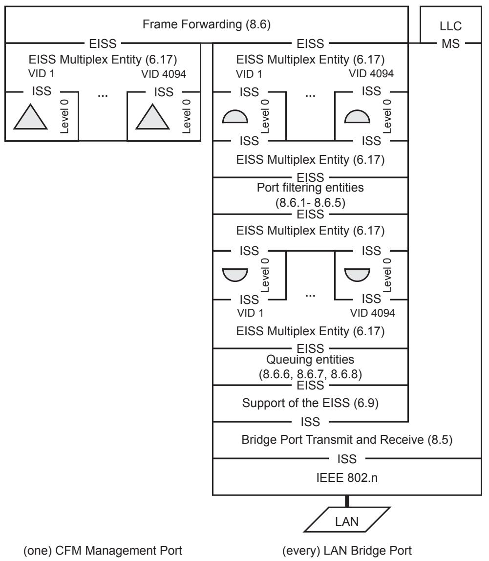
Figure 22-13—CFM in the enterprise environment
This simple configuration enables the administrator to use LBMs and LTMs to diagnose network faults among the Bridges of the network. In addition, specific high-priority VLANs, e.g., a VLAN interconnecting key routers and file servers for a large enterprise, could be explicitly monitored via CFM.
In a large enterprise, separate Maintenance Domains can be established, along with an accompanying enterprise-wide Maintenance Domain at a higher MD Level, in order to define and enforce separate spheres of responsibility for separate network administrations, e.g., in different departments in a university. The boundaries between Maintenance Domains might well coincide with administratively imposed boundaries between MSTP Regions.
22.8 Implementing CFM on Bridges that implement earlier revisions of IEEE Std 802.1Q
It might or might not be easy to implement CFM in a VLAN Bridge that implement earlier revisions of IEEE Std 802.1Q. The problems are best illustrated by a three-port Bridge as illustrated in Figure 22-14. Each of the three Bridge Ports A, B, and C is configured with MEPs and MIPs at the MD Levels shown in the figure.
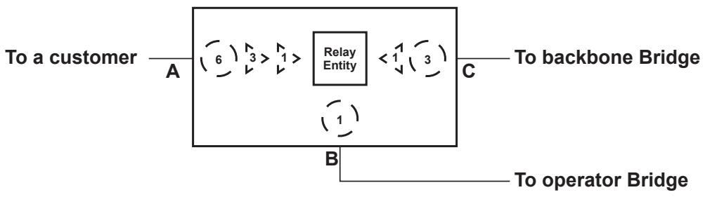
Figure 22-14—CFM on a Bridge that implements IEEE Std 802.1Q-2005
If a CCM at MD Level 3 enters the Bridge from Bridge Port C, that CCM will be passed to both of the other Bridge Ports A and B. It will not exit Bridge Port A, however, because there is a MEP at MD Level 3 on that Bridge Port. It will, however, pass through Bridge Port B to the other operator Bridge. One can easily imagine configuring MAC Address Registration Entry in the Bridge for the MD Level 3 group address shown in Table 8-15 that permits that group address to pass through the Bridge Ports B and C, but not through Bridge Port A, and also sends the CCM to a CFM module in the Bridge’s Higher Layer Entities, perhaps residing on the Management Port of 22.7, for processing. It is precisely so that MAC Address Registration Entries can be used in this manner that CCMs and LTMs are required to use the group addresses in Table 8-16 and Table 8-15.
A potential problem for some implementations can be seen if readers ask what happens if that same CCM at MD Level 3 enters from Bridge Port A. In that case, the CCM does not exit either of Bridge Ports B or C, because Bridge Port A has a MEP at MD Level 3 to stop it; MAC Address Registration Entries prevent frames from leaving a Bridge Port, not from entering one. Many Bridges have the ability to filter incoming frames based on the destination MAC address and/or the contents of the frame; either facility will enable this CCM to be stopped. In order to support both a Down MEP attached to no VID, and a Down MEP attached to a tagged VID at a lower MD Level than the no-VID MEP, the Bridge filters frames based on both the MAC address and whether the frame is tagged.
23 MAC status propagation
Individual LANs, each operating its own MAC and media access method-specific procedures, can be connected by one or more TPMRs to form a composite LAN that is transparent to other Bridges and stations and their configuration protocols. The MAC Status Protocol (MSP) ensures that changes in the connectivity provided by the composite LAN results in changes in the MAC_Operational status parameter (IEEE Std 802.1AC) at each of the attached Bridges and stations, just as if they were connected to an individual LAN.
NOTE 1—MSP is designed only for use with point-to-point LANs.
MAC_Operational provides rapid notification of connectivity failures and prompts the necessary initial protocol behavior to ensure that new connectivity has not caused an instantaneous data loop. If this MAC status parameter were not propagated by a TPMR, Bridge protocols would have to rely on periodic transmissions to detect connectivity changes. On their own these periodic transmissions take longer to detect failures, and cannot detect the possibility of data loops until they have been created, as illustrated by the following examples.
Figure 23-1 shows a TPMR connecting two Bridge Ports.
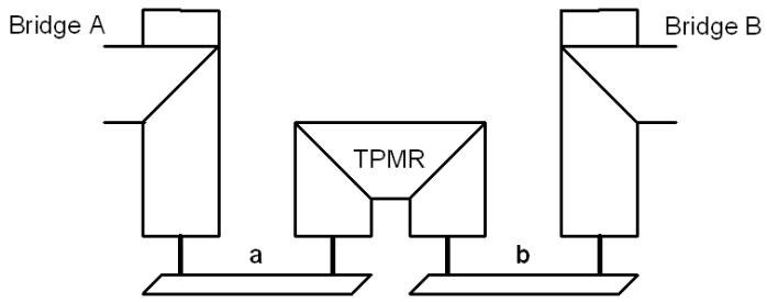
Figure 23-1—TPMR connecting two Bridge Ports
Assume that Bridge A is the spanning tree Designated Bridge for the LAN that comprises the individual LANs a and b and the TPMR, and that Bridge B’s spanning tree Root Port is shown. If a fails and the TPMR does not propagate MAC_Operational, Bridge B will not reselect its Root Port until it has timed out the last BPDU from A.
Figure 23-2 shows a link that uses two TPMRs, perhaps because LAN c uses a non-802 technology together with an appropriate convergence function.
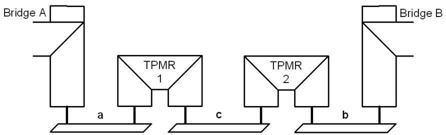
Figure 23-2—TPMR chain connecting Bridge Ports
Without MAC_Operational propagation, failure of c will not be immediately visible to either Bridge. Worse, if c fails and is restored after a while, both A and B will believe themselves to be Designated Bridge for the composite LAN, and will forward frames until one receives a BPDU from the other, even if a data loop has been created.
When working correctly the MAC Service provides bidirectional connectivity or no connectivity at all. MAC_Operational is TRUE for each of two peers connected to the same LAN if they can communicate, and FALSE for either or both if they cannot. Protocols, such as the spanning tree protocols, that make use of MAC_Operational to detect new connectivity and initialize state machines rely on the last peer that sees MAC_Operational transition TRUE to enforce any necessary behavior after a connectivity change. For example, it is the last of two connected Bridge Ports to be powered on that enforces the necessary delay prior to setting operEdge TRUE (13.27).
NOTE 2—MAC_Operational being TRUE within a single station does not guarantee connectivity to any peer. Even if connected by a point-to-point LAN, the peer could have just reinitialized. It is not possible, given only the use of the LAN medium for communication, to arrange for two peers to transition MAC_Operational at exactly the same time.
This clause defines media-independent propagation of MAC status between TPMRs and to attached stations, as follows. It
a) Models MAC status propagation within the Bridge architecture used to describe a TPMR (23.1)
b) Provides an overview of MSP (23.2)
c) Specifies state machines for MSP operation (23.3–23.9)
d) Specifies the addressing, protocol identification, format, encoding, and validation of MAC Status Protocol Data Units (MSPDUs, 23.13–23.16)
The term MAC status propagation (3.134) describes the overall process of communicating a MAC_Operational parameter value through one or more TPMRs. MSP can use link status notification31 (3.105) between some Bridges and end stations and MAC status notification (3.133) between others. These two notification methods differ, as follows:
e) Link status notification uses frames to convey information about MAC_Operational. It does not interrupt or prevent other communication between adjacent Bridges. However, it requires both the source and destination of the notification to implement additional protocol. Since it does not prevent communication it cannot, by itself, prevent loops caused by new connectivity.
f) MAC status notification uses a layer management interaction with the local MAC Entity to change MAC_Operational for a peer user of the MAC Service provided by an individual LAN. It is equivalent to bringing a link down, and is generally effective for MACs with specific point-to-point support. It also interrupts all other communication, including the use of in-band management to rectify an underlying problem.
Where management of a TPMR is permitted through one of its ports, the failure of an individual LAN not in the communication path does not cause MAC status propagation to prevent management connectivity. In Figure 23-2, for example, the failure of LAN b does not prevent connectivity to TPMR 2 from Bridge A. When b recovers, MAC_Operational for Bridge A’s Port is “blipped,” i.e., taken FALSE for a brief period and allowed to return TRUE, thus meeting the requirement for transition when connectivity changes.While this slows the recognition of newly available connectivity, that is rarely an issue since several seconds hysteresis should be applied to any MAC_Operational status transition to prevent higher layer protocols “flapping.”
23.1 Model of operation
The model of operation presented in this clause allows the description of MSP functionality to be consistent with that of the general Bridge architecture and operation (8.2, 8.3). Implementations of a TPMR may adopt any internal model of operation compatible with the externally visible behavior specified.
The additional entities that model MSP operation, and their relationship to the other processes and entities that model the operation of a TPMR are illustrated in Figure 23-3. They comprise the following:
a) A MAC Status Shim (MSS, 23.1.1) for each Port, which allows MSP to control the value of MAC_Operational presented to the TPMR Port connectivity function (8.5.2) and hence to the frame transmission and reception functions of the MAC Relay Entity, Higher Layer Entities, and MAC Status Propagation Entity (MSPE).
b) The MSPE, which implements MSP, controlling each MSS to ensure that frames are not forwarded by the MAC Relay Entity until status propagation is complete, transmitting and receiving frames to support link status notification, and controlling the individual LAN’s MAC to provide MAC status notification.
NOTE—In a TPMR the priority signaling functions shown in Figure 23-3 are provided by 6.20 Support of the ISS with signaled priority.
MSPDUs are sent to a standard group address. They are received by the MSPE, but are forwarded by the MAC Relay Entity (like any other frame) in order to communicate without a delay in each TPMR. The MSPE attaches to each Port by a TPMR Port connectivity function (8.5.2) that allows it to transmit to and receive from the attached individual LAN only, as shown in Figure 23-3.
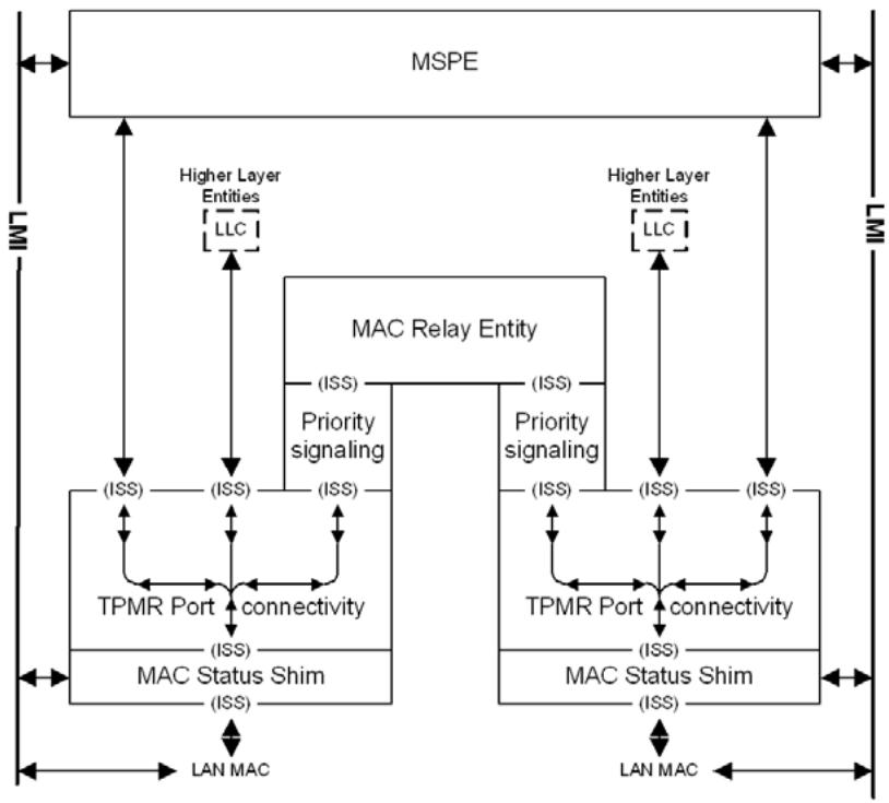
Figure 23-3—MSSs and the MSPE
23.1.1 MAC Status Shim (MSS)
The MSS allows MSP to control the transmission and reception of frames through a Port by all the entities (including the MAC Relay Entity) supported by the TPMR Port Connectivity function (8.5.2). Each transmit request from the latter at the MSS’s upper ISS-SAP results in a corresponding transmit request at the lower ISS-SAP supported by the LAN MAC and each receive indication from the lower ISS-SAP results in a corresponding receive indication at the upper ISS-SAP, without omission or duplication, and with identical parameters, if and only if MAC_Operational for the upper ISS-SAP is TRUE.
The values of the MAC status parameters presented at the upper ISS-SAP are determined as follows:
MAC_Enabled: The value of this parameter is FALSE if the value of STM’s disableMSS variable is TRUE. Otherwise, the value of this parameter is TRUE. STM communicates the value of its disableMSS variable using a Layer Management Interface (LMI).
MAC_Operational: The value of this parameter is TRUE if and only if the MSS’s MAC_Enabled parameter is TRUE and the value of the MAC_Operational parameter provided by the LAN MAC at the lower ISS-SAP is TRUE.
The MSPE uses the LMI to control and receive status from each MSS and individual LAN MAC, allowing generic management requests and indications to be tailored to the requirements of different MACs, as well as providing a way for one MSS to propagate status to another (via the MSPE), even though MAC_Operational for the MSS’s upper ISS-SAP is FALSE.
23.1.2 Relationship of CFM to the MSS
MEPs may be placed above or below the MSS. A MEP placed in the lower position and partnered with another MEP so that the pair spans a chain of TPMRs would obscure the LAN MAC’s MAC_Operational parameter and interfere with the operation of MSP. For this reason, MEPs that protect individual LANs should be placed below MSS, and MEPs that protect chains of TPMRs should be placed above MSS.
23.2 MAC Status Protocol (MSP) overview
This clause provides examples of MSP operation as time sequence diagrams that show the following:
a) Exchange of MSPDUs transmitted and received to support link status notification.
b) The values of MAC_Operational and MAC_Enabled provided by the following:
1) Each MSS, at its upper ISS-SAP, to the TPMR Port connectivity function.
2) Each LAN MAC to the MSS, at the latter’s lower ISS-SAP.
The value of MAC_Operational provided by the MSS is TRUE if, and only if the MSS’ MAC_Enabled is TRUE and the value of MAC_Operational provided to the MSS by the LAN MAC is TRUE. The latter can be TRUE only if MAC_Enabled is TRUE for both the LAN MAC and its peer in the other station connected to the LAN. The MSPE can use the LMI to disable the MSS in order to prevent communication until MAC status propagation has occurred, and to disable the LAN MAC in order to provide MAC status notification to a peer service user. This clause uses the symbols defined in Table 23-1 to show combinations of the MAC status parameter values for each Port.
Table 23-1—Time sequence diagram symbols
<table><tr><td colspan="2"></td><td>👍</td><td>👎</td><td>💡</td><td>👍</td><td>💡</td></tr><tr><td rowspan="2">MSS</td><td>MAC_Operational</td><td>T</td><td>F</td><td>F</td><td>F</td><td>F</td></tr><tr><td>MAC_Enabled</td><td>T</td><td>T</td><td>F</td><td>F</td><td>—</td></tr><tr><td rowspan="2">LAN MAC</td><td>MAC_Operational</td><td>T</td><td>F</td><td>F</td><td>T</td><td>F</td></tr><tr><td>MAC_Enabled</td><td>T</td><td>T</td><td>T</td><td>T</td><td>F</td></tr></table>
$\mathrm { \Delta T = T R U E , F = F A L S E , \mathrm { \_ m e r ~ T R U E ~ o r ~ F A L S E } }$
Throughout this protocol description, the term LAN is used to refer to individual LANs connecting adjacent TPMRs or a TPMR and an adjacent Bridge. A chain is a series or part of a series of TPMRs connected by LANs, and a link is the connectivity provided by a chain between non-TPMR devices that communicate at a higher (sub) layer and perceive the entire link as a single transparent LAN.
The number of TPMRs in the following examples is deliberately high, four where one or two might be more common, in order to show all the necessary aspects of protocol behavior.
Signaling the addition of new or restored connectivity is considered first, as it is more difficult than signaling failure. Figure 23-4 shows the response to a new or recovered LAN connection in a link between two Bridges that do not implement MSP—and thus require MAC status notification.
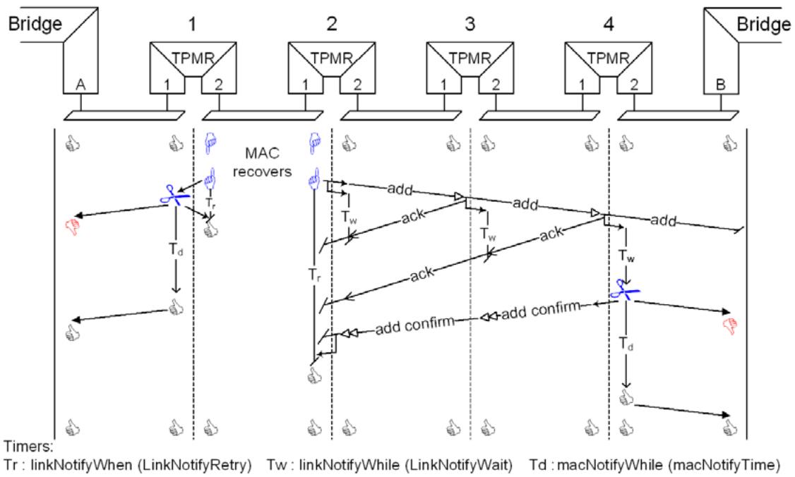
Figure 23-4—Adding connectivity
Before the LAN that connects TPMR 1 to TPMR 2 is MAC_Operational, each MSPE disables its MSS (). This allows the MSPE to intercept the new connectivity as the LAN MAC asserts MAC_Operational (). TPMR 2 propagates the new status to its other Port, transmitting an add MSPDU. TPMR 2 does not necessarily know that TPMR 3 implements MSP (or indeed is a TPMR) but uses the default MSP configuration—waiting before resorting to MAC status notification and starting a linkNotifyWhile timer (as do TPMRs 3 and 4) on receipt of the add (which is forwarded by the Relay Entity). Each TPMR responds to the add with an ack that clears the timer, but the Bridge at the end of the chain does not (as it does not implement MSP). When TPMR 4’s timer expires, its MSPE disables the LAN MAC (), ensuring that MAC_Operational becomes FALSE () for the Bridge’s Port, and starts a macNotifyWhile timer. When that timer expires, the MSPE reenables the LAN MAC so that the Bridge Port’s MAC_Operational can become TRUE () once more. As well as disabling the LAN MAC for its Port 2, TPMR 4 also transmitted an add confirm through Port 1, and receipt of this add confirm by TPMR 2 causes the latter to cancel its retry timer (linkNotifyWhen). The initial value of macNotifyWhile (MacNotifyTime) is sufficient for the add confirm to reach the TPMR 2, and for that TPMR’s MSPE to enable the MSS, thus ensuring that there is connectivity between the Bridges connected by the link when they have both reported MAC_Operational TRUE to their local protocol clients.
In Figure 23-4 the MSP configuration of TPMR 2’s Port 2 differs from that for Port 1 of TPMR 1. The latter is explicitly configured to use MAC status notification immediately without waiting to see if its peer implements MSP.
Figure 23-5 illustrates the operation of MSP when the connectivity provided by an individual LAN is lost. The MSPE for each of the TPMR ports directly attached to the failed LAN begins by disabling the MSS for that Port () to ensure that connectivity does not ‘flap’. Otherwise, the protocol proceeds as for connectivity addition, except that loss and loss confirm are used instead of add and add confirm, and the MSSs attached to the failed LAN are left disabled. The final state of the link components is the initial state assumed in Figure 23-4—both attached Bridges have seen MAC_Operational transition to indicate that the connectivity has changed, and the TPMRs in each of the two chains can be reached and managed (if their individual configuration permits) through the attached Bridge Ports.
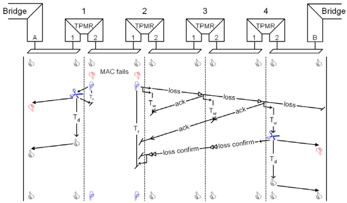
Figure 23-5—Losing connectivity
In the examples above, if an add, or loss is lost then the TPMR Port that transmitted or relayed that MSPDU will revert to using MAC status notification, as will a TPMR that fails to receive the ack from the next (or a subsequent) TPMR in the chain. If the MSPDU is lost on a LAN removed from the TPMR that initiated the link status notification, then that notification will be retried on expiry of the linkNotifyWhen timer, which also serves to protect against the loss of an add confirm or loss confirm.
Loss of a frame due to physical corruption is rare in LAN technologies, and frame losses due to buffer overrun are not expected when connectivity is being added (as the link is not usable prior to the addition) nor when a loss of connectivity is being signaled (as that connectivity loss will have prevented other frames from being added to the link). The loss of an MSPDU is most likely to be due to failure of one of the LANs, or to interruption of a TPMR’s relay functionality by another MSS whose MSPE is also waiting for confirmation that a connectivity change that it has detected has been propagated to the end of the link. MSP does not, and cannot, ensure that information about each and every connectivity change reaches both ends of the link. Unless link status notification or MAC status notification is disabled or the individual LANs fail to report MAC_Operational correctly, MSP does ensure that any change in connectivity is accompanied by one or more notifications at each end of the link, and that a continuous period during which MAC_Operational is reported TRUE at both ends of the link provides unchanged connectivity from 1 second after the start of the period to 1 second before the end. This guarantee meets the requirements implicit in the initial transmission and retransmission strategies of well designed protocols. Protocol clients of the MAC Service should not use the difference between loss and add MSPDUs to take different actions on receipt, though the distinction can be useful to a network administrator when investigating connectivity changes.
Figure 23-6 provides a common example of simultaneous change. TPMR 2 is powered on and initializes both its ports. When the LAN MAC becomes operational, each Port attempts to send a notification through the other, but cannot as they are both waiting for the connectivity addition to be confirmed. However, in this eventuality, each Port can provide the other with the confirmation required, because the peer system for each of the individual LANs will also have seen the initial MAC_Operational transition and will have initiated a notification toward its end of the link.
NOTE—The SNM state machine transition direct from SNM:LINK_NOTIFICATION to SNM:MAC_NOTIFYING supports this behavior (see Figure 23-11).
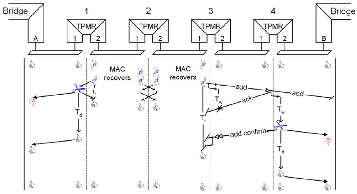
Figure 23-6—TPMR recovery
If the individual LAN that recovers (or loses) connectivity is at the end of the link, MSP ensures that the other end of the link is also aware of the status change as illustrated in Figure 23-7. This figure also shows the effect on MSP of including two nonstandard relays in the chain. Provided they (and their attached LANs) never fail, MSP can continue to operate as intended.
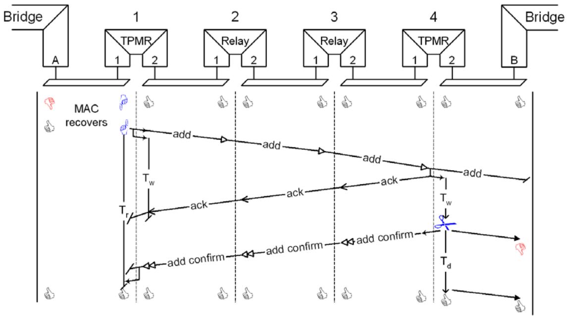
Figure 23-7—Notification from one end of the link to the other
If TPMR 4 is configured to use MAC status notification immediately, it does not return an ack as the add confirm can be sent almost immediately (see Figure 23-8).
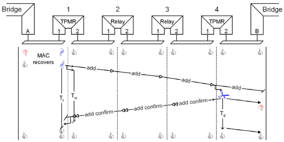
Figure 23-8—Immediate MAC status notification at the end of a link
23.3 MSP state machines
The operation of the MSPE is represented by an instance of each of the following for each Port of the TPMR:
a) A Status Transition state machine (STM, 23.8)
b) A Status Notification state machine (SNM, 23.9)
c) A Receive Process (23.10)
d) A Transmit Process (23.11)
Figure 23-9 shows the state machine variables that are used to communicate between these machines and processes, and that support management control over their operation. Variables prefixed with ‘r.’ are those of the corresponding state machines of the other Port of the TPMR.
The notational conventions used in Figure 23-9 and in the specification of the state machine are identical to those used in the specification of MSTP (Clause 13) and RSTP and are defined in Annex E.
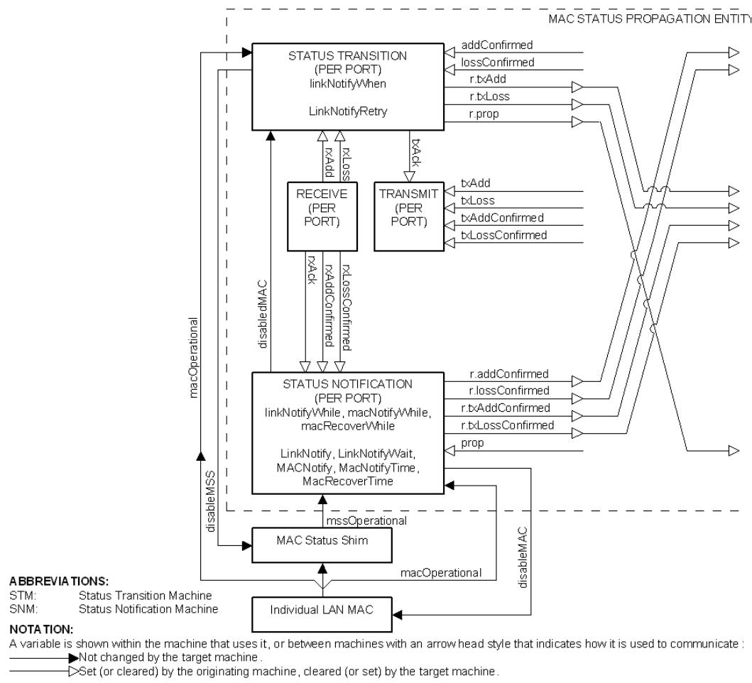
Figure 23-9—MSPE state machine overview
Port 1’s STM monitors MAC_Operational transitions for its own LAN, and tells Port 2’s Transmit process to send add or loss link notifications and Port 2’s SNM to monitor the progress of status notification, using MAC status notification if necessary. Port 2’s SNM receives the ack that indicates that it should wait for link status notification to complete, and the add confirm or loss confirm that indicates that completion. Whether link status or MAC status notification is used, Port 2’s SNM tells Port 1’s STM when the notification has been confirmed, so the latter does not have to retry the notification. Port 1’s SNM provides the same service to Port 2’s STM.
A loss or add notification that is received from Port 1’s own LAN is handled by its STM, which propagates the notification to Port 2’s SNM (in the same way as a local MAC_Operational transition) while transmitting an ack on Port 1’s LAN. Similarly Port 2’s STM transmits an ack for a link status notification received on its own LAN, and propagates the notification to Port 1’s SNM.
23.4 State machine timers
Timers are implemented by variables that are decremented on each timer tick, with timer expiry occurring when they reach zero.
23.4.1 linkNotifyWhen
Causes a link status notification to be sent on each expiry until the original status transition is confirmed.
23.4.2 linkNotifyWhile
Started when a change is first propagated through the Port, on expiry allows MAC status notification.
23.4.3 macNotifyWhile
Sets the time for which the MAC is disabled for MAC status propagation.
23.4.4 macRecoverWhile
Sets the time for which the MAC is permitted to be nonoperational, after being disabled, before the link is reported as lost.
23.5 MSP performance parameters
These parameters are not modified by the operation of MSP but are treated as constants by the state machines. They can be managed independently for each TPMR Port—default values and permissible ranges are specified in Table 23-2.
Table 23-2—MSP performance parameters
<table><tr><td>Parameter</td><td>Recommended or default value</td><td>Permitted range</td></tr><tr><td>LinkNotify</td><td>TRUE</td><td>TRUE or FALSE</td></tr><tr><td>LinkNotifyWait</td><td>0.4 s</td><td>0.2–1.0 s</td></tr><tr><td>LinkNotifyRetry</td><td>1.0 s</td><td>0.1–1.0 s</td></tr><tr><td>MACNotify</td><td>TRUE</td><td>TRUE or FALSE</td></tr><tr><td>MACNotifyTime</td><td>0.2 s</td><td>0.01–0.5 s</td></tr><tr><td>MACRecoverTime</td><td>0.1 s</td><td>0.02–0.5 s</td></tr></table>
23.5.1 LinkNotify
TRUE if the Port uses link status notification to propagate MAC status, and will wait to allow link status notification to succeed before using MAC status notification.
NOTE—If LinkNotify is FALSE, the TPMR still forwards loss and add notifications transmitted by other TPMRs prior to using MAC status notification, but the TPMR will not originate link status notifications.
23.5.2 LinkNotifyWait
The initial value of the linkNotifyWhile timer.
23.5.3 LinkNotifyRetry
The initial value of the linkNotifyWhen timer of the other TPMR Port.
23.5.4 MACNotify
TRUE if the Port uses MAC status notification.
23.5.5 MACNotifyTime
The initial value of the macNotifyWhile timer.
23.5.6 MACRecoverTime
The initial value of the macRecoverWhile timer.
23.6 State machine variables
23.6.1 BEGIN
This is a Boolean variable controlled by the system initialization process. A value of TRUE causes all TPMR state machines to continuously execute their initial state. A value of FALSE allows all state machines to perform transitions out of their initial state, in accordance with the relevant state machine definitions.
23.6.2 addConfirmed
Set by the other Port’s SNM to tell STM that the addition has been confirmed. Cleared by STM.
23.6.3 disableMAC
Set by SNM to instruct the individual LAN MAC (via an LMI) to disable itself in a way that will cause MAC_Operational to be FALSE for the peer user of the MAC Service provided by that LAN.
NOTE—The state machines do not assume that a client of the MAC can tell whether the MAC is not operational because that client has disabled it, or whether some other client has disabled it.
23.6.4 disabledMAC
Set by the SNM when it has set disableMAC and for MACRecoverTime after disableMAC has been reset, so that the STM does not conclude that a loss notification should be sent through the other TPMR Port.
23.6.5 disableMSS
Set (or reset) by the STM to instruct the MSS (via an LMI) to set its MAC_Enabled status parameter to FALSE (correspondingly, TRUE).
23.6.6 lossConfirmed
Similar to addConfirmed but confirms a loss.
23.6.7 macOperational
The value of MAC_Operational for the individual LAN MAC.
23.6.8 mssOperational
The value of MAC_Operational provided by the MSS to the TPMR Port’s Bridge transmit and receive function.
23.6.9 prop
Set by the other Port’s STM to Add or Loss to notify SNM that a change is being propagated through the Port. Reset by SNM to None.
23.6.10 rxAck
Set by the Receive process to tell SNM that an acknowledgment has been received. Cleared by SNM.
23.6.11 rxAdd
Set by the Receive process to tell STM that an add notification is being propagated through the TPMR. Cleared by STM.
23.6.12 rxAddConfirm
Set by the Receive process to tell SNM that an add confirm has been received. Cleared by SNM.
23.6.13 rxLoss
Similar to rxAdd, but for a loss.
23.6.14 rxLossConfirm
Similar to rxAddConfirm, but for a loss confirm.
23.6.15 txAck
Set by the STM to instruct the Transmit process to send an acknowledgment. Cleared by the Transmit process.
23.6.16 txAdd
Set by the other Port’s STM to cause transmission of an add notification. Cleared by the Transmit process.
23.6.17 txAddConfirm
Set by the other Port’s SNM to cause transmission of an add confirm (through this Port) confirming that a received add message has been acted upon. Cleared by the Transmit process.
23.6.18 txLoss
Similar to a txAdd but causes a loss message to be transmitted.
23.6.19 txLossConfirm
Similar to a txAddConfirm but causes a loss confirm message to be transmitted.
23.7 State machine procedures
No procedures are defined beyond those represented in the state machines.
23.8 Status Transition state machine (STM)
The STM shall implement the function specified by the state diagram in Figure 23-10 and the attendant definitions contained in 23.4 through 23.7.
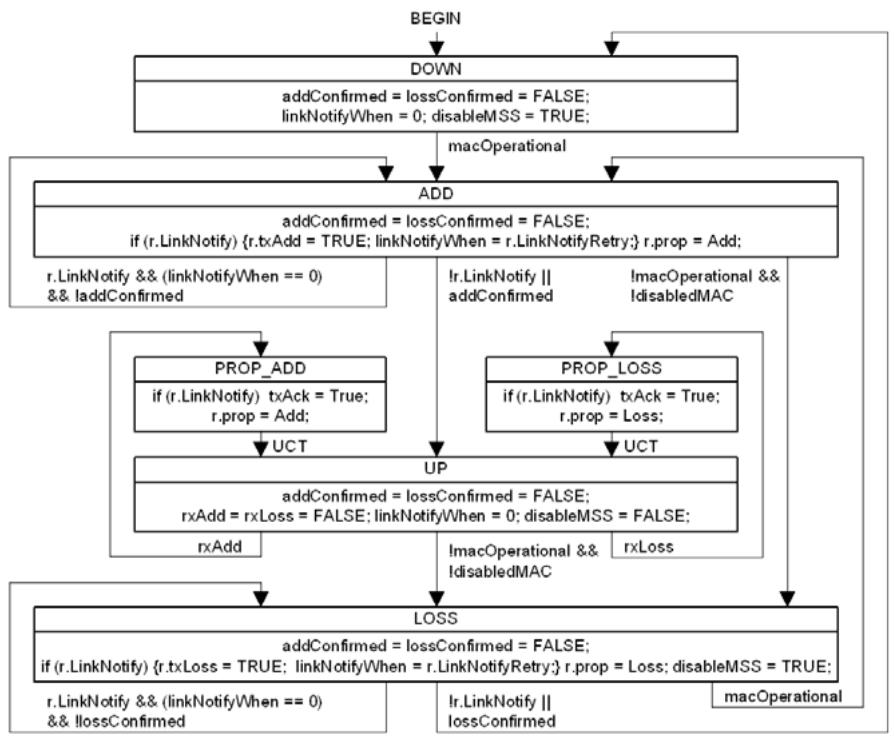
Figure 23-10—Status Transition state machine (STM)
23.9 Status Notification state machine (SNM)
The SNM shall implement the function specified by the state diagram in definitions contained in 23.4 through 23.7.
Figure 23-11 and the attendant
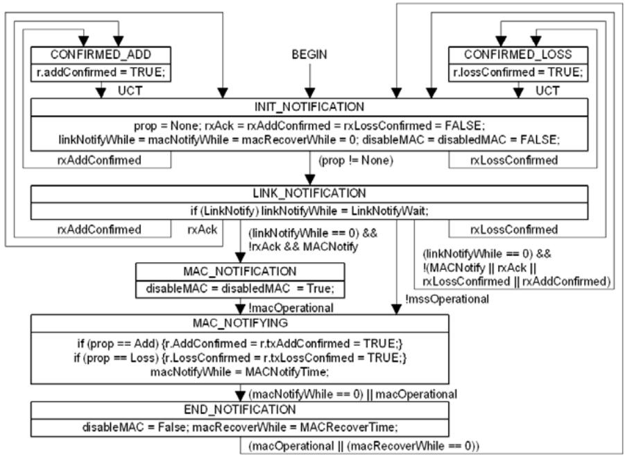
Figure 23-11—Status Notification state machine (SNM)
23.10 Receive Process
The Receive Process shall receive and validate MSPDUs as specified in 23.16.
23.11 Transmit Process
The Transmit Process shall transmit and encode MSPDUs as specified in 23.13–23.15. If the Transmit Process is instructed to transmit an MSPDU before it has had the opportunity to transmit a prior MSPDU, that prior MSPDU shall be discarded and not transmitted. If the MAC_Operational status provided by the MSS for the Port is FALSE, the MSPDU shall be discarded and not transmitted.
23.12 Management of MSP
An implementation of MSP in a TPMR
a) May allow the performance parameters (23.5) to be read by management.
b) May allow the performance parameters (23.5) to be modified by management.
c) May maintain each of the following counts for one or both ports of the TPMR:
acksTransmitted: The number of acks transmitted (23.6.15) by the Port’s Transmit Process as a consequence of txAck being set.
addNotificationsTransmitted: The number of adds transmitted (23.6.16) by the Port’s Transmit Process as a consequence of txAdd being set.
addConfirmationsTransmitted: The number of add confirms transmitted (23.6.17) by the Port’s Transmit Process as a consequence of txAddConfirm being set.
lossNotificationsTransmitted: The number of losses transmitted (23.6.18) by the Port’s Transmit Process as a consequence of txLoss being set.
lossConfirmationsTransmitted: The number of loss confirms transmitted (23.6.19) by the Port’s Transmit Process as a consequence of txLossConfirm being set.
— acksReceived: The number of acks received (23.6.10) by the Port’s Transmit Process.
addNotificationsReceived: The number of adds received (23.6.11) by the Port’s Receive Process.
addConfirmationsReceived: The number of add confirms received (23.6.12) by the Port’s Receive Process.
lossNotificationsReceived: The number of losses received (23.6.13) by the Port’s Receive Process.
lossConfirmationsReceived: The number of loss confirms received (23.6.14) by the Port’s Receive Process.
addEvents: The number of transitions to STM:ADD directly from STM:DOWN or STM:LOSS (23.8).
lossEvents: The number of transitions to STM:LOSS directly from STM:UP or STM:ADD (23.8).
macStatusNotifications: The number of transitions to SNM:MAC_NOTIFICATION (23.9).
23.13 MSPDU transmission, addressing, and protocol identification
MSPDUs are transmitted and received using the service provided by an LLC entity that uses, in turn, a single instance of the MAC Service provided at an MSAP. In a TPMR the MSPE transmits and receives the MSPDUs, and the MSAP is provided by the TPMR Port connectivity function as illustrated in Figure 23-3. Each MSPDU is transmitted as a single MAC Service request, and received as a single MAC Service indication, with the following parameters:
a) destination address (23.13.1)
b) source address (23.13.2)
c) MSDU
d) priority (23.13.3)
The MSDU of each request and indication comprises an number of octets that provide EtherType protocol identification (23.13.4) followed by the MSPDU proper (23.15).
NOTE 1—For the purposes of this standard, the term “LLC entity” includes entities that support protocol discrimination using the EtherType field as specified in IEEE Std 802a™-2003 [B5].
NOTE 2—The complete format of an MSP frame “on the wire” or “through the air” depends not only on the MSPDU format, as specified in this clause, but also on the media access method-dependent procedures used to support the MAC Service.
23.13.1 Destination MAC Address
The destination address for each MAC Service request used to transmit an MSPDU shall be the group
23.13.2 Source MAC Address
The source address for each MAC Service request used to transmit an MSPDU shall be an individual address associated with the MSAP at which the request is made.
23.13.3 Priority
The priority associated with each MAC Service request should be the default associated with the MSAP. Transmitted MSPDUs are not VLAN tagged or priority tagged.
23.13.4 EtherType use and encoding
All MSPDUs are identified by the EtherType specified in Table 23-3.
Table 23-3—MSP EtherType assignment
<table><tr><td>Assignment</td><td>Value</td></tr><tr><td>MAC Status Protocol EtherType</td><td>22-E2</td></tr></table>
Where an individual LAN MAC supports direct encoding of EtherTypes (as does IEEE Std 802.3, for example) the LLC entity shall encode the MSP EtherType as the first two octets of the MPDU. Otherwise (for IEEE Std 802.11, for example), the MSP EtherType shall be encoded in the initial octets of the MPDU according to the procedures specified in IEEE Std 802 for Subnetwork Access Protocols (SNAP).
NOTE—The SNAP discriminator comprises the octets AA-AA-03-00-00-00 prepended to the MSP EtherType.
23.14 Representation and encoding of octets
All MSPDUs consist of an integral number of octets, numbered starting from 1 and increasing in the order that they are put into a MAC frame. The bits in each octet are numbered from 1 to 8, where 1 is the loworder bit. When consecutive octets are used to encode a binary number, the lower numbered octet contains the more significant bits of the binary number.
When the encoding of (an element of) an MSPDU is represented using a diagram in this clause, the following representations are used:
a) Octet 1 is shown toward the top of the page, higher numbered octets being toward the bottom.
b) Where more than one octet appears on a given line, octets are shown with the lowest numbered octet to the left, higher numbered octets being to the right.
c) Within an octet, bits are shown with bit 8 to the left and bit 1 to the right.
23.15 MSPDU structure
The MSPDU comprises the octets following the MSP EtherType. All MSPDUs comprise a Protocol Version (23.15.1) and a Packet Type (23.15.2). See Figure 23-12.
<table><tr><td></td><td>Octet</td></tr><tr><td>Protocol Version (23.15.1)</td><td>1</td></tr><tr><td>Packet Type (23.15.2)</td><td>2</td></tr></table>
Figure 23-12—MSPDU structure
23.15.1 Protocol Version
The MSP Protocol Version is encoded in all MSPDUs as a single octet, representing an unsigned binary number. Its value identifies the version of MSP supported by originator of the MSPDU. An implementation conforming to this specification shall encode the value 0000 0000 in this field. All other values are reserved.
NOTE—TPMRs that relay an MSPDU do not change its Protocol Version.
23.15.2 Packet Type
The MSP Packet Type is encoded as a single octet, representing an unsigned binary number. Table 23-4 lists the Packet Types specified by this standard, and the state machine variables set to indicate reception and transmission of MSPDUs of that type. All other possible values of the Packet Type field are reserved and shall not be used.
Table 23-4—MSP Packet Types
<table><tr><td>Packet Type</td><td>Value</td><td>Transmission</td><td>Reception</td></tr><tr><td>MSP-Add</td><td>0</td><td>txAdd (23.6.16)</td><td>rxAdd (23.6.11)</td></tr><tr><td>MSP-Loss</td><td>1</td><td>txLoss (23.6.18)</td><td>rxLoss (23.6.13)</td></tr><tr><td>MSP-Add Confirmed</td><td>2</td><td>txAddConfirm (23.6.17)</td><td>rxAddConfirm (23.6.12)</td></tr><tr><td>MSP-Loss Confirmed</td><td>3</td><td>txLossConfirm (23.6.19)</td><td>rxLossConfirm (23.6.14)</td></tr><tr><td>MSP-Ack</td><td>4</td><td>txAck (23.6.15)</td><td>rxAck (23.6.10)</td></tr></table>
23.16 Validation of received MSPDUs
To ensure that backward compatibility is maintained for future versions of this protocol, the validation and protocol version handling for all MSPDUs, follows general rules developed for this and other protocols. A received MSPDU shall be processed as specified by Table 23-4 if and only if
a) The destination MAC address is the group address specified (23.13.1); and
b) The MSPDU is identified by the MSP EtherType encoded as specified in 23.13.4; and
c) The received MSPDU contains at least two octets, i.e., at least the Protocol Version and Packet Type; and
d) The Packet Type is one of the values specified in Table 23-4.
Otherwise, the received MSPDU shall be discarded. No other checks shall be applied to received MSPDUs, in particular the value of the Protocol Version is not checked and MSPDUs of length greater than the minimum of two octets are accepted as valid.
23.17 Other MSP participants
An end station or non-TPMR Bridge attached to the end of a TPMR link can participate in link status notification, avoiding the need for the last TPMR in the chain to use MAC status notification and thus speeding the transition of the link to an operational state. Such a participant receives MSPDUs, but acts only on a received loss or add, notifying its protocol clients of the change in connectivity, and responding immediately by transmitting an add confirm or loss confirm as appropriate. There is no need for such a participant to transmit an add, loss, or ack, or act upon a received ack, add confirm or loss confirm, or to initiate MAC status notification.
24 Bridge performance
This clause specifies a set of parameters that represent the performance of a Bridge. These parameters have been selected to allow a basic level of confidence to be established in a Bridge, for use in an initial determination of its suitability for a given application. They cannot be considered to provide an exhaustive description of the performance of a Bridge. It is recommended that further performance information be provided and sought concerning the applicability of a Bridge implementation.
The following set of performance parameters is defined:
a) Guaranteed Port Filtering Rate, and a related time interval $T _ { F }$ , that together characterize the traffic for which filtering is guaranteed.
b) Guaranteed Bridge Relaying Rate, and a related time interval $T _ { R }$ .
24.1 Guaranteed Port Filtering Rate
For a specific Bridge Port, a valid Guaranteed Port Filtering Rate, in frames per second, is a value that, given any set of frames from the specific Bridge Port to be filtered during any $T _ { F }$ interval, the Forwarding Process shall filter all of the set as long as all of the following are true:
a) The number of frames in the set does not exceed the specific Bridge Port’s Guaranteed Port Filtering Rate multiplied by $T _ { F }$
b) The Guaranteed Port Filtering Rate of each of the other Bridge Port(s) is not exceeded.
c) The Guaranteed Bridge Relaying Rate is not exceeded.
d) Relayed frames are not discarded due to output congestion (8.6.7).
e) The information upon which the filtering decisions are based has been configured in the FDB prior to the start of time interval $T _ { F }$ .
24.2 Guaranteed Bridge Relaying Rate
For a Bridge, a valid Guaranteed Bridge Relaying Rate, in frames per second, is a value that given any set of frames from the specific Bridge Port to be relayed during any $T _ { R }$ interval, the Forwarding Process shall relay all of the set as long as all of the following are true:
a) The number of frames in the set does not exceed the Bridge’s Guaranteed Bridge Relaying Rate multiplied by $T _ { R }$ .
b) The Guaranteed Port Filtering Rate of each Bridge Port is not exceeded.
c) Relayed frames are not discarded due to output congestion (8.6.7).
d) The information upon which the forwarding decisions are based has been configured in the FDB prior to the start of time interval $T _ { R } .$ .
24.3 RSTP performance requirements
This subclause places requirements on the performance of the Spanning Tree Protocol Entities of Bridges in a Bridged Network to ensure that RSTP operates correctly.
The delay between the occurrence of an external event and the action or actions mandated by the RSTP specification as a consequence of the event shall not exceed the Maximum RSTP processing delay specified in Table 24-1.
External events subject to this provision of this specification shall include the following:
a) Transmission of a BPDU by another Bridge on a LAN to which the Bridge is attached.
Specified actions subject to this provision shall include the following:
b) Transmissions of BPDUs on all Ports mandated by the RSTP specification, with the exception of transmissions delayed by the Port Transmit state machine (13.34) to enforce transmit rate limits.
c) Ceasing to learn or forward frames.
The delay between internal timer related events and the transmission of all BPDUs on Ports mandated by the RSTP specification as a consequence shall not exceed the Maximum BPDU transmission delay specified in Table 17-5. Timer events subject to this provision of this specification shall include the following:
d) Decrementing of txCount by the Port Transmit machine, thus allowing a BPDU transmission if transmit rate limits were being enforced.
e) Expiry of the helloWhen timer (13.25.3).
Table 24-1—Transmission and reception delays
<table><tr><td>Parameter</td><td>Absolute maximum value</td></tr><tr><td>Maximum RSTP processing delay</td><td>1.0 s</td></tr><tr><td>Maximum BPDU transmission delay</td><td>0.2 s</td></tr></table>
25 Support of the MAC Service by PBBNs
A PBBN comprises a set of BEBs interconnected by some or all of the S-VLANs supported by a PBN (see Clause 16). Each BEB provides interfaces that encapsulate (or verify the encapsulation of) customer frames, thus allowing Customer MAC (C-MAC) addresses and VIDs to be independent of the Backbone MAC (B-MAC) addresses and VIDs administered by the PBBN operator and used to relay those frames across the backbone. The S-VLANs used to encapsulate customer frames are known as Backbone VLANs (B-VLANs), and the resources that support those VLANs are usually considered to be part of the PBBN.
NOTE 1—The term Customer used in the context of PBBs may refer to a first Provider who is purchasing service from a second Provider. The first Provider deploys a PBN or a PBBN within its domain. The second Provider deploys a PBBN within its domain. In this case, the first Provider is identified as a Customer with respect to the second Provider. The term Customer used here may alternatively refer to each of a pair of Providers communicating as peers.
Figure 25-1 shows peer BEBs within the MAC sublayer and their relationship to customer and backbone bridging functions. The right-most BEB shown is modeled as comprising two types of VLAN Bridge components, an I-component and a B-component, connected together. The two BEBs on the left of the figure each comprise a single VLAN Bridge component of different types. The left-most BEB has a single Icomponent, while the BEB just to the right of the left-most BEB has a B-component. A T-component may also be used in place of an I-component.
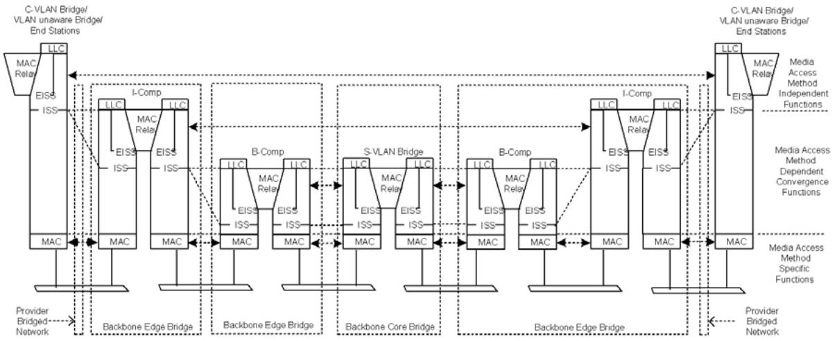
Figure 25-1—Internal organization of the MAC sublayer in a PBBN
Each I-component or T-component is responsible for encapsulating frames received from customers and assigning each frame to a backbone service instance. The backbone service instance consists of a set of BEBs that support a given customer’s S-VLANs, and is uniquely identified within the PBBN by an I-SID. The customer frame is encapsulated by an I-TAG, which includes the I-SID, and a set of source and destination B-MAC addresses. The B-MAC addresses identify the BEBs of the backbone service instance where the customer frame will enter and exit the PBBN. If the I-component or T-component does not know which of the other BEBs provides connectivity to a given customer address, it uses a default encapsulating B-MAC address that reaches all the other BEBs in the backbone service instance. Each I-component learns the association between customer source addresses received (encapsulated) from the backbone and the backbone source address, so subsequent frames to that address can be transmitted to the correct BEB.
A PBBN or a series of PBBNs providing the MAC Service to attached end stations is typically modeled as a symmetric sequence of relay functions, as illustrated in Figure 25-1. The outermost peer relay functions are identified as I-components. The next peer relay functions in the sequence are identified as B-components. Between the peer B-components are one or more S-VLAN relay functions. A B-component relay forms the service layer to an I-component relay. A B-component relay forwards frames taking into account the identity of a B-VLAN (B-VID), while an I-component relay forwards frames taking into account the identity of an S-VLAN (S-VID).
A single B-component is responsible for relaying encapsulated customer frames to and from I-components and T-components, either within the same BEB or externally connected, checking that ingress/egress is permitted for frames with that I-SID, translating the I-SID (if necessary) and using it to assign the supporting connection parameters (backbone addresses if necessary and VIDs) for the PBBN, and relaying the frame to and from the PNP(s) that provide connectivity to the other Bridges within and attached to the backbone. A B-component performs the same functions when relaying frames to and from another B-component when two PBBNs interconnect (26.6.2).
The number of I-components (zero or more), T-components (zero or more), and B-components (zero or one) within a given BEB is a direct consequence of the type and number of external interfaces supported by that BEB. The I-components, T-components, and B-component may be in the same BEB or may be in different BEBs. The types of BEBs may be classified as I-BEB, B-BEB, T-BEB, and ITB-BEB as depicted in Figure 25-2, where ITB-BEB covers all valid combinations of multi-component BEBs, e.g., IB-BEB.
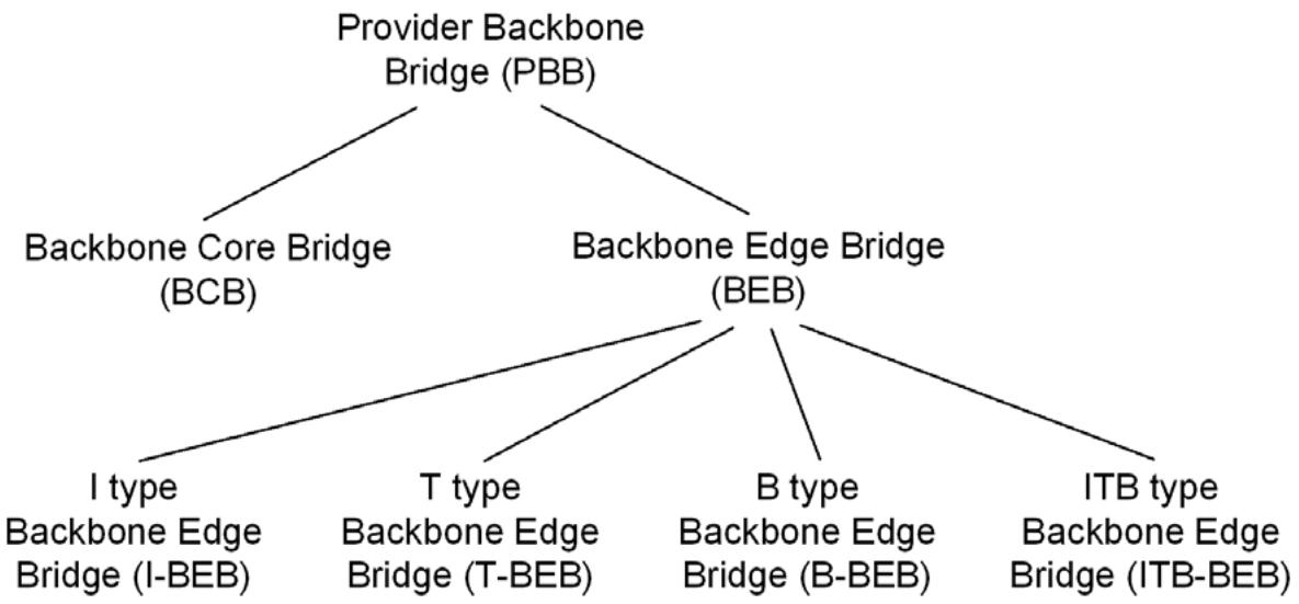
Figure 25-2—PBB terminology
This clause discusses the following aspects of PBBN service:
a) Service transparency (25.1)
b) Customer service interfaces (25.2, 25.3, 25.4, 25.5)
c) Service instance segregation (25.6)
d) Service instance and backbone service instance selection and identification (25.7)
e) Service priority and drop eligibility selection (25.8)
f) Service access protection (25.9)
NOTE 2—This standard makes use of the term service as defined by the OSI Reference Model (IS0/IEC 7498-1). In this sense, a service comprises a set of primitives and associated parameters, provided by one protocol layer in the architectural model to the protocol layer above, and the causal relationships between the primitives invoked by an upper layer protocol entity in one system with those resulting indications to a peer entity in another system. The term service used by backbone providers, while including layering concepts, goes far beyond this formal definition, and commonly specifies some or all of the following: interfacing considerations across multiple protocol layers (including physical connectors, for example); selection of interface points; interfacing equipment; QoS guarantees and measurement methods; charging methods and responsibilities; connectivity verification and other management tools; and regulatory issues.
25.1 Service transparency
The operation of PBBNs is, by design, largely transparent to Provider Bridges and PBNs as illustrated by Figure 25-1. The service provided by BEBs is transparent to the use of the MAC Service by end stations attached to the CBNs through PBNs and transparent to the operation of media access method-independent functions by Customer Bridges.
The service is not transparent to the operation of media access method-dependent convergence functions or to the operation of the media access method-specific functions specified by standards for each media access method. Media access method-dependent and -specific functions operate between Bridges—whether Customer Bridges, Provider Bridges, or PBBs—attached to the same LAN.
25.2 Customer service interface
A backbone provider can offer to customers one or more types of service interfaces, each providing different capabilities for service selection, priority selection, and service access protection (25.7, 25.8, 25.9). In some cases it is assumed the customer provides an S-VLAN component of a Provider Bridge while in other cases, more generic customer systems are also allowed. There are four basic types of customer service interfaces— Port-based, S-tagged, I-tagged, and transparent service interface. The customer service interface types are summarized by Figure 25-3.
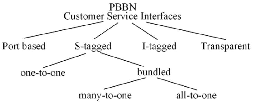
Figure 25-3—Customer service interface types
In all cases, segregation of different service instances is achieved at an interface wholly under the control of the backbone provider, and by verification of customer provided parameters that provide service instance selection. Stronger authentication and authorization of the attached customer systems may be achieved by use of IEEE Std 802.1X.
NOTE—The term service access protection describes provision of service access over multiple access LANs and (or) nodes with redundancy and rapid failover in case of failure of an access LAN or attached equipment.
Access to a given backbone service instance can be provided through different types of customer interfaces.
25.3 Port-based service interface
A PBBN may provide a Port-based service interface for customer attachment. The PBBN Port-based interface provides the same type of service to a customer as the PBN Port-based interface described in 15.3. A Port-based service interface is delivered on a CNP provided by a BEB as illustrated in Figure 25-4 and Figure 25-5. A Port-based service interface may attach to a C-VLAN Bridge (5.9), MAC Bridge, router, or end-station. The service provided by this interface forwards all frames without an S-TAG over the backbone on a single backbone service instance. All frames with an S-TAG that has a non-null VID are discarded by a Port-based service interface.
The Port-based service interface requires specific constraints on the configuration of the I-component. Each I-component CNP providing a Port-based interface is associated with one and only one VIP with exactly the same parameters for their tagging functions support. More specifically both CNP and VIP
a) Have the Acceptable Frame Types parameter configured to Admit Only Untagged and Prioritytagged frames;
b) Have equal PVID values;
c) Are exclusive members of the same PVID member set;
d) Are members of the PVID untagged egress set.
Figure 25-4 illustrates a customer system attached to a PBBN over a Port-based service interface.
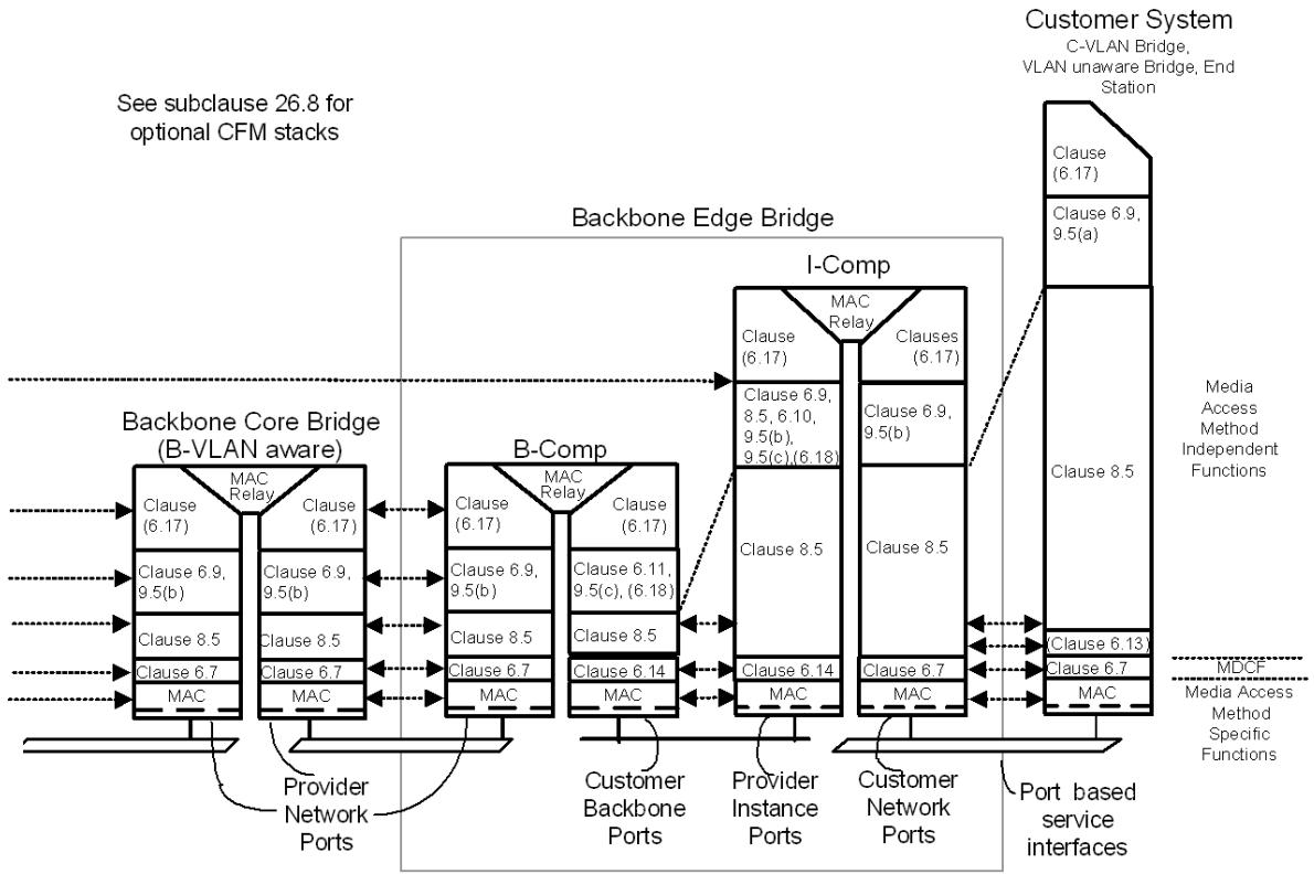
Figure 25-4—Port-based service interface
Figure 25-5 shows an example of equipment used to implement an unprotected Port-based service interface. For details on redundant connections and equipment, see 25.9. An I-component may support one or more Port-based service interfaces. Each CNP may be associated with one Port-based service interface. A CNP is connected to a customer system (or network) using a LAN.
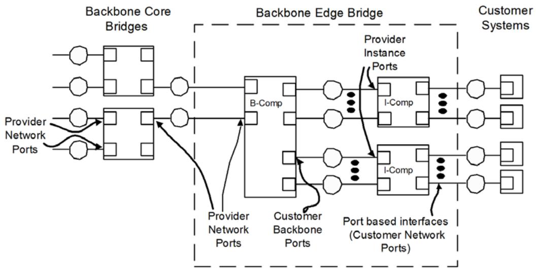
Figure 25-5—Port-based interface equipment
25.4 S-tagged service interface
The S-tagged service interface maps a service instance from a PBN, identified by an S-VID, to a backbone service instance on the PBBN, identified by an I-SID. There are two types of S-tagged service interfaces— one performing a one-to-one mapping of S-VIDs to I-SIDs and the other bundling S-VIDs to I-SIDs. Frames that are mapped to the I-SID are carried over the PBBN while frames that are not mapped to an I-SID are not carried over the PBBN.
NOTE 1—The restriction that each PBN S-VLAN map to a single backbone service instance on the PBBN allows the PBN equipment receiving frames to correctly identify the service instance used to deliver that frame and prevents the configuration of the I-component to create a multipoint service from point-to-point service instances, which could result in accidental creation of data loops. The backbone provider can offer a multipoint service through appropriate configuration of the B-VLAN component.
A PBBN may provide an S-tagged service interface for attachment to customer PBNs (15.5). An S-tagged service interface is provided by a BEB over a CNP as illustrated by Figure 25-7 and Figure 25-8. The attached Provider Bridges can in turn provide Port-based, C-tagged, or S-tagged service interfaces to their customers as described in 15.2, 15.3, 15.4, and 15.5.
The S-tagged service interface has the variations shown in Figure 25-3 under the S-tagged branch. The first variation, called a one-to-one S-tagged interface, uses a one-to-one mapping between S-VIDs and I-SIDs. This interface variation maps each S-VID to a single I-SID for use over the PBBN. The one-to-one mapped interface does not carry the S-TAG over the PBBN. The DEI and PCP bits may be regenerated on ingress and are then carried in the I-DEI and I-PCP bits in the I-TAG across the PBBN. On egress from the one-toone S-tagged interface, the S-TAG can be deduced from the I-TAG received from the PBBN (the I-SID is mapped to an S-VID, the I-DEI and I-PCP bits may be regenerated and are then carried in the DEI and PCP bits).
The second S-tagged service interface variation is the bundling S-tagged service interface. This interface variation maps multiple S-VIDs to a single I-SID for delivery over the PBBN. To allow the remote end to reconstruct the S-VID, this interface variation will carry an S-TAG over the PBBN. On a bundled S-tagged interface, the DEI and PCP bits of the S-TAG may be regenerated and are then carried in both the DEI and PCP bits of the S-TAG and the I-DEI and I-PCP bits of the I-TAG over the PBBN.
A special case of the bundling S-tagged service interface is where all S-VIDs are mapped to a single I-SID. This special case is called an all-to-one bundling S-tagged service interface. The I-component used for an all-to-one bundled S-tagged service interface is constrained to supporting a single S-tagged service interface.
Figure 25-6 illustrates the information passed over each of the ISS interfaces of a BEB.
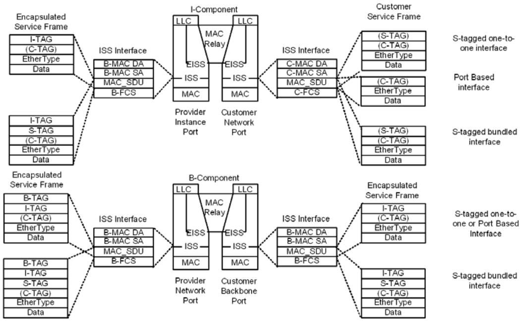
Figure 25-6—Encapsulated service frames at ISS
Figure 25-7 illustrates a customer network attached to a PBBN using an S-tagged service interface. The customer network uses Provider Bridges with S-VLAN components for connecting to the PBBN. The PBBN in turn is composed of BEBs interfacing to the customer Provider Bridges and BCBs used to forward frames between the BEBs.
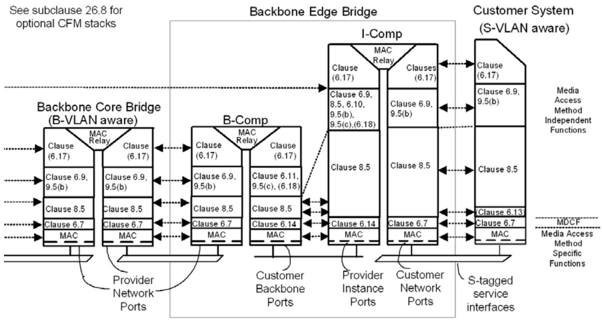
Figure 25-7—S-tagged service interface
Figure 25-8 shows an example of equipment used to implement an unprotected S-tagged service interface. For details on redundant connections and equipment, see 25.9. In this diagram, a BEB is formed by connecting two I-components and a B-component. These connections may be over a backplane or over a LAN. An I-component may support one or more S-tagged service interfaces. When an I-component supports an all-to-one bundled S-tagged service interface, the entire I-component must be dedicated to a single Stagged service interface. Each CNP may be associated with one S-tagged service interface. A CNP is connected to a customer system (or network) using a LAN.
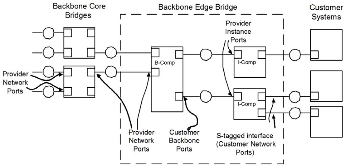
Figure 25-8—S-tagged service interface equipment
NOTE 2—It is always possible to build equipment that includes both BEB and Provider Edge Bridge components. In particular, it is possible for a BEB to support a C-tagged service interface (15.4) for attachment to a CBN by including a C-VLAN component with PEPs that connect to the CNPs of an I-component. A BEB can also support an RCSI (15.6) by including a C-VLAN component and a Port-mapping S-VLAN component.
25.5 I-tagged service interface
A PBBN may provide a native I-tagged service interface for attachment to another PBBN or for attachment to a customer’s PIP. An I-tagged service interface can provide access to all the backbone service instances within a PBBN. Access to backbone service instances is controlled by the configuration of the CBP service instance tables (6.11). Each I-SID delivered over the I-tagged service interface by a customer identifies a service instance that will be carried over the PBBN. Service instances are carried over the PBBN inside a B-VLAN selected by the CBP. The customer must provide the B-DA for frames delivered to an I-tagged service interface.
Figure 25-9 illustrates a customer network attached to a PBBN using an I-tagged service interface. The customer network uses a BEB with an I-component (26.6.1) or a B-component (26.6.2) connecting to the PBBN. The PBBN in turn is composed of BEBs interfacing to the customer and BCBs in the core of the PBBN used to forward frames between the BEBs.
An I-tagged service interface may be provided at a CBP of a BEB as illustrated by Figure 25-9 and Figure 25-10. In this service interface, the I-SID provided over the service interface within the I-TAG is mapped 1-1 to an I-SID within the PBBN. As illustrated, a customer (or peer) may attach to the I-tagged service interface through a CBP. In this configuration, each PBBN is attached at a CBP.
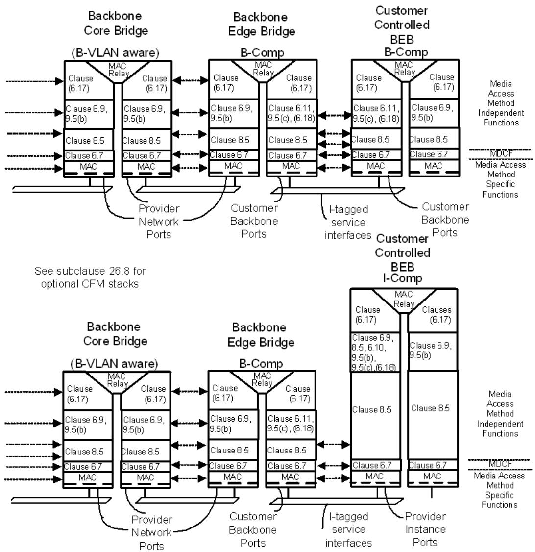
Figure 25-9—I-tagged service interface
Figure 25-10 shows an example of equipment used to implement an unprotected I-tagged service interface. For details on redundant connections and equipment, see 25.9. A B-component may support one or more I-tagged service interfaces. Each CBP may be associated with one I-tagged service interface. These CBP are connected to a customer system (or network) using an Ethernet LAN.
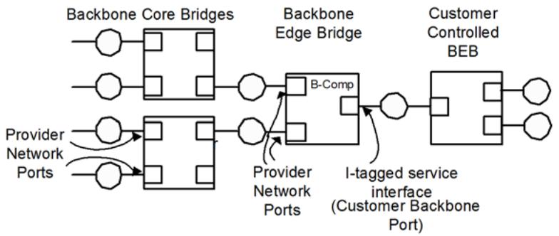
Figure 25-10—I-tagged service interface equipment
NOTE—A protected I-tagged service interface will have more than one PIP and can have a single backbone service instance, identified by an I-SID, enabled on more than one of those ports. This creates the potential for transit traffic on that backbone service instance to pass through the I-BEB without being delivered to a CNP. If this behavior is not desired, then the protected I-tagged service interface should be configured such that any single service instance is only enabled on a single PIP at any given time, or that only a single PIP is forwarding at any given time.
25.6 Service instance segregation
Segregation of data frames associated with different instances of MAC Service is achieved by supporting each service instance with a backbone service instance identified by an I-SID and ensuring that
a) No service frames are transmitted through a CBP without an I-TAG.
b) No frames are accepted, i.e., received and relayed, from any customer system without first being subject to service instance selection.
c) No frames are delivered to any customer system without explicit service instance identification.
d) Prior to transmission through a PNP of a BEB, service frames are received either through an I-component’s CNP or through a CBP. When the customer is attached to a CNP, the port is under the control of the backbone provider and is exclusively accessed by a single customer. In this case, the I-component used to support the CNP is under the control of the Backbone provider and is attached to a CBP through a PIP that is also under the control of the backbone provider and that may be shared with multiple customers. When the customer is attached to a CBP, the port is under the control of the provider and is exclusively accessed by a single customer. All frames received through the CNP or CBP (depending on how the customer is attached) must correspond to a service instance or instances that the customer is permitted to access. (The method used to ensure the port is attached to the specified customer and therefore secure is beyond the scope of this standard. See IEEE Std 802.1X.)
e) The BCBs and the B-component of each BEB within the PBBN can only be controlled by the provider.
A single backbone service instance may support many customer service instances. Each customer service instance is supported by a single backbone service instance.
25.7 Service instance selection and identification
Service instance selection is provided to the attached customer system by the Port-based, S-tagged, or I-tagged service interfaces (25.3, 25.4, 25.5). In the Port-based interface, only one backbone service instance is offered to the attached customer and the CNP of the I-component is configured to accept only untagged or priority tagged frames. In all S-tagged service interfaces, the CNP of the I-component is configured with Enable Ingress Filtering (8.6.2) and the Port is only included in the Member Set for S-VLANs corresponding to service instances that the customer is permitted to use. The service instance for each frame received by the attached customer system is identified in the same way as frames transmitted using the same interface, but not necessarily in the same way that the service instance is selected or identified at other interfaces. In the Itagged service interface, the CBP of the B-component is configured (12.16.5, 6.11) with the acceptable backbone service instances and I-SID values for use by the customer. A single backbone service instance can support any combination of Port-based, S-tagged, or I-tagged service interfaces.
NOTE—The means used by a backbone provider and a customer to determine the S-VIDs and I-SIDs used by the customer to select and identify a given service instance are outside the scope of this standard.
25.8 Service priority and drop eligibility selection
For all service interface types, the service priority is selected using the received priority for each frame. For S-tagged and Port-based service interfaces, the priority and drop eligibility may be regenerated using the Priority Regeneration Table (6.9.4). For I-tagged service interfaces, the priority and drop eligibility may be regenerated using procedures of 6.11.
The mechanism for determining the received priority varies with the type of service interface. Service priority selection is provided for Port-based service interfaces using the received priority signaled from the media access method of the port. If the media access method used to attach to the interface does not directly support priority, this will result in the selection of a single value for all frames. An attached system may also signal priority to a Port-based service interface on a per-frame basis by priority-tagging frames with an S-TAG that has a null VID (6.13).
Service priority selection is provided by S-tagged service interfaces using the PCP and DEI parameters conveyed in the S-TAG of each frame. An S-tagged service interface can provide a single backbone service instance for all S-VIDs received, and in this way functions like a Port-based service interface with the addition of the capability of delivering S-tagged service frames (whose S-TAG has a non-null VID).
Service priority selection is provided by I-tagged interfaces using the received priority decoded from the I-PCP and I-DEI fields in the I-TAG.
25.9 Service access protection
A customer system (or systems) that is part of a single PBN or that contains a customer operated Icomponent or B-component can attach to a PBBN using a protected service interface providing multiple LANs and (or) nodes, thus providing fault tolerance through redundancy of the service interface components. Three classes of service access protection may be supported (see Figure 25-11 and Figure 25-12), which provide for unprotected service interface, for link-level redundancy at the access link or link and node redundancy at the access point. An access service interface may be a Class I, II, III access service interface.
Protected Port-based, S-tagged, and I-tagged service interfaces are depicted in Figure 25-11 and Figure 25-12, respectively.
Class I service interfaces depicted in these figures are unprotected service interfaces providing a single LAN and node. Class I service interface equipment is depicted in Figure 25-5, Figure 25-8, and Figure 25-10. These provide no redundancy and therefore will fail if any LAN or component fails.
Class II service interfaces are link protected service interfaces that provide multiple LANs; however, they do not provide any node redundancy. Class II service interfaces are tolerant of single or multiple LAN failures. These provide no node redundancy and therefore will fail if any node fails.
Class III service interfaces are link and node protected service interfaces providing multiple LANs and multiple nodes. Class III service interfaces are tolerant of single or multiple LAN failures and/or single or multiple node failures. The operation of a Class III service interface switches between access nodes within both the customer and provider networks; therefore, protection switching over a Class III service interface always results in state changes spreading over the customer and provider networks.
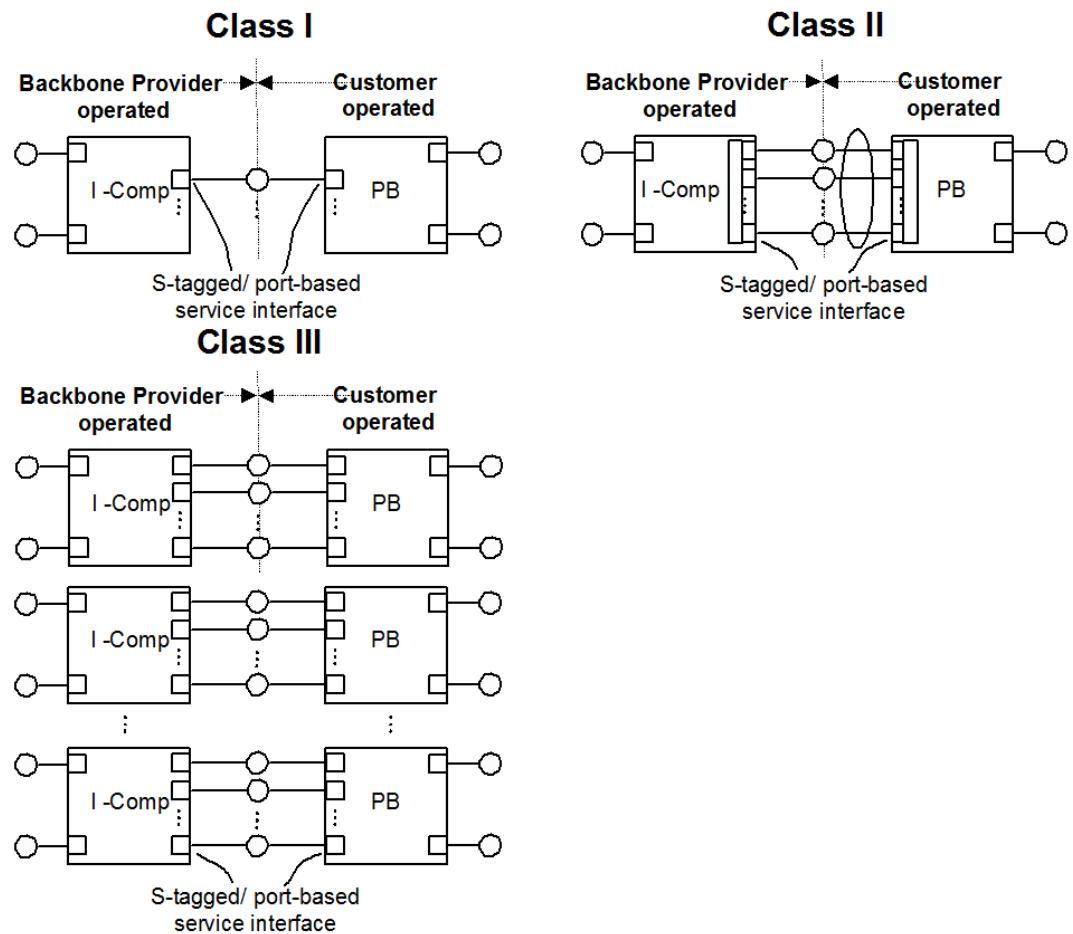
Figure 25-11—S-tagged and Port-based service interface access classifications
To attach a PBN to a PBBN, the following rules must be maintained to ensure loop-free operation over the extended network:
a) Each PBN and PBBN prevents forwarding loops by running an independent spanning tree.
b) Each PBN connects to other PBNs only through a PBBN.
c) Each PBN ensures that no data frame passes through more than one BEB attachment point into or out of the PBBN. An attachment point is a single LAN connection to a PBBN. This connection may be part of a protected or unprotected Port-based (see Figure 25-4), S-tagged (see Figure 25-7), or Itagged service interface (see Figure 25-9). A PBN may use L2GP (13.40) to ensure only a single link is active when using a backup link to the PBBN.
d) Each PBN ensures that it attaches any given S-VLAN to no more than one PBBN.
NOTE—When an attached PBN uses the L2GP (13.40) to enforce criterion c), then the PBBN may implement a Class I, II, or III protection interface. If the PBBN is configured for Class I or II protection, then it will provide multipoint services with the services delivered to two or more Class I or II interfaces for attachment to the PBN. In this case, the PBN is responsible for selecting one of the two attachments using the L2GP to ensure criterion c). If the PBBN is configured for Class III protection, then the PBN must support MVRP over the access links to inform the PBBN which S-VIDs are active on which LAN connections.
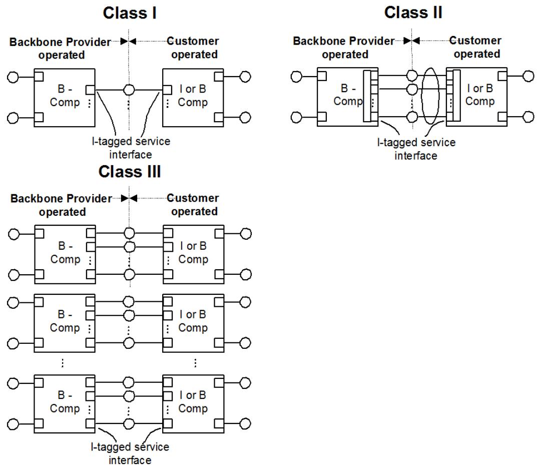
Figure 25-12—I-tagged service interface access protection classifications
25.9.1 Class II redundant LANs access protection
A Class II redundant interface is implemented using IEEE Std 802.1AX (Link Aggregation). Using Link Aggregation, a single CNP and associated PNP of a Provider Bridge, or CBP and associated PIP, may be implemented using multiple LANs. A failure on any of the LANs implementing the link will cause all traffic to migrate to the remaining LAN. CFM may run both on the aggregate and on each individual link as shown in Figure 22-8.
It is desirable for the distribution algorithm used on a Class II interface to divide traffic between the multiple links based on the service instance. One distribution algorithm that always retains a service on a single LAN is to place all the traffic on one of N links. In the event of a failure, all traffic is shifted to the highest priority remaining link. This distribution algorithm has the advantage that it provides for full reserved bandwidth on the backup link.
Another distribution algorithm that divides traffic by service and also allows traffic on all redundant links is to divide the traffic by either the S-VID or the I-SID. Distributing traffic based on the S-VID would be used for traffic over multiple LANs comprising an S-tagged interface, while distributing traffic based on the I-SID would be used for traffic over multiple LANs comprising an I-tagged interface. With either of these distribution schemes, services are allocated to one of the LANs used to implement the provider CNP or CBP and the customer PNP, PIP, or CBP. In the event of a failure, the services are moved to the remaining LANs.
25.9.2 Class III simple redundant LANs and nodes access protection
A Class III interface uses redundant LANs to connect a primary and one or more secondary customer nodes to a primary and one or more secondary BEBs. The operation protects the interface against failures on any of the interconnecting LANs or nodes used on each side of the interface. It is possible to use Class II protected interfaces for each link of the Class III interface. In this case, the Class II protection procedures must happen first and complete before a Class III protection switch begins.
For a Class III interface, each customer node is connected to a BEB using a single LAN. The interface is provisioned with a priority for each LAN which is part of the interface. Each of the LANs is constantly monitored using either PHY management, CFM, or both. In operation, a Class III interface uses only the highest priority operating LAN for traffic. The other LANs are protection paths. In a Class III interface, any switch in the LAN used for traffic will also switch both the customer node and the PBBN BEB since the connections of a Class III interface are sets composed of a customer node, a LAN, and a BEB.
When providing a Class III protected S-tagged interface, multiple CNPs, each on a different BEB, are used to create a single S-tagged interface. Each LAN of the S-tagged interface executes CFM at the port level to detect failures over the interface LANs. Information from CFM is used by the customer to determine which LANs of the S-tagged interface are operating and which are inactive. Each customer network runs MSTP to determine which S-VLANs are active on which LANs of the Class III interface. To avoid loops through the Class III interface, either the I-components participate in the customer network spanning tree (13.42), or the ports on the customer equipment that connects to the I-components are configured as Layer 2 Gateway Ports (13.40). Upon an active link failure between customer node and its corresponding BEB or upon the customer node failure, the customer network switches to one (or more) of the backup links and informs the PBBN which S-VLANs are active on which links using MVRP (11.2) on the access LANs. The BEB(s), upon receiving the MVRP message(s) from the customer network, generate the corresponding MRP-based message(s) for the affected I-SIDs and send these messages over the associated B-VLANs. The far-end BEBs, upon receiving these messages, will flush their C-MAC entries in their FDB corresponding to the affected I-SIDs.
When providing a Class III protected I-tagged interface, multiple CBPs, each on a different B-BEB, are used to create the single I-tagged interface. In this scenario, each B-BEB is connected via a single link to the customer I-BEB where the link can be Class II protected. The customer I-BEB is in turn connected via multiple CNPs to the customer network. Each customer network runs MSTP to determine which S-VLANs are active on which LANs of the Class III interface. To avoid loops through the Class III interface, either the I-components participate in the customer network spanning tree (13.42), or the ports on the customer equipment that connects to the I-components are configured as Layer 2 Gateway Ports (13.40). PHY management or port-level CFM is used to detect failures over the interface LANs between the customer I-BEBs and the customer network. When a failure is detected, the customer network informs the customer I-BEBs which S-VLANs are active on which links using MVRP (11.2). The customer I-BEBs in turn notify the provider B-BEBs using MRP-based messages corresponding to the effected I-SIDs. The provider B-BEBs relay this message to the other BEBs in the PBBN over the associated B-VLANs. The farend BEBs, upon receiving these messages, will flush their C-MAC entries in their FDB corresponding to the effected I-SIDs. Each LAN of the I-tagged interface also executes PHY management or CFM at the port level to detect failures over the I-tagged interface. In case of a complete I-tagged interface failure between the customer I-BEB and the provider B-BEB, the I-BEB uses this info to deactivate all its CNP ports toward the customer network.
25.10 Support of the MAC Service by a PBB-TE Region
A PBB-TE Region comprises a continuous set of IB-BEBs and BCBs, capable of providing TESIs, that have allocated a common subset of B-VIDs to the control of an external agent (8.9) responsible for setting up Ethernet Switched Paths (ESPs). Each IB-BEB that belongs to a PBB-TE Region can provide interfaces that encapsulate customer frames in ESPs, thus allowing the PBBN operator to offer TESIs.
A PBB-TE Region providing the MAC Service to attached stations is modeled as a sequence of relay functions, as illustrated in Figure 25-13. The MST Configuration Table associated with each BCB or Bcomponent of an IB-BEB specifies a set of VIDs, each of which may be exclusively used throughout the PBB-TE Region to form part of an ESP identifier. Such a VID is called an ESP-VID and is associated with a special value of the MSTID in the MST Configuration Table, the TE-MSTID (8.9), indicating that the VID is not under the control of a spanning tree protocol.
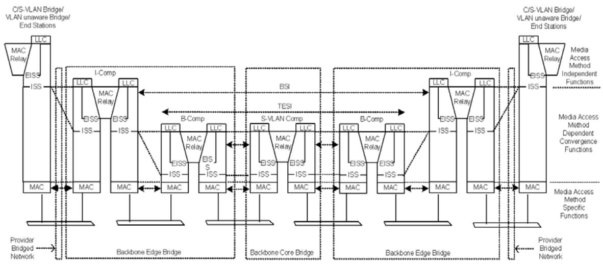
Figure 25-13—Internal organization of the MAC sublayer in a PBB-TE Region
The I-components of IB-BEBs supporting PBB-TE are responsible for encapsulating frames received from customers and allocating each frame to a backbone service instance and for decapsulating frames received from the network via backbone service instances. The allocation of customer frames to backbone service instances that will be transported by TESIs is done at the PIP as described in 6.10. At the PIP the customer frame is encapsulated by an I-TAG, which includes the I-SID, and a set of source and destination B-MAC addresses. The source B-MAC address is the PIP MAC address that is configured to take the same value as the CBP MAC address of the internally connected CBP on the B-component. As a result, the B-MAC addresses of frames associated with TESIs, the ESP MAC addresses, are always equal to the CBP MAC addresses.
CBPs on B-components in IB-BEBs supporting PBB-TE use the I-SID to map the encapsulated customer frames to TESIs or B-VLANs (6.11). Figure 25-13 depicts a TESI providing the MAC Service at two CBPs. For an I-SID mapped to a TESI, the Backbone Service Instance table contains the terminating CBP’s MAC address, the ESP-DA, and the ESP-VID of the associated ESP. I-SIDs mapped to a B-VLAN must not use a B-VID from the ESP-VID space. The B-Component MAC relay forwards frames belonging to an ESP between the CBP and PNPs or between PNPs using the ESP-DA and ESP-VID as described in 8.6.
25.10.1 Provisioning TESIs
ESPs are provisioned in a PBB-TE Region by an external agent. This replaces the spanning tree protocols and populates the filtering tables of the corresponding B-components and BCBs by creating static filtering table entries for the ESP MAC addresses and ESP-VIDs (Figure 25-14).
The ability of a PBB-TE Region to utilize an external management or control plane is facilitated by PBB because the PIP MACs and correspondingly the ESP MAC addresses can be managed by the Provider and therefore can all be identified in the Provider’s topology by the external management or control plane.
The external PBB-TE management/control plane is responsible for maintaining and controlling all the active topology information to support point-to-point or point-to-multipoint ESPs over the PBB-TE Region. The PBB-TE active topology can co-exist with active topologies associated with spanning tree protocols and the allocation to a specific active topology is governed by the B-VID value. The PBB-TE external agent takes control of the ESP-VID range on the Bridges in a PBB-TE Region.
Similar to the forwarding connectivity created by the operation of spanning tree and learning, the PBB-TE management/control plane can form an active topology of CBP rooted trees, from each CBP belonging to a PBB-TE Region to a specific subset of any other CBPs in this region. These traffic engineered trees define the path(s) taken by the frames that belong to ESPs within the PBB-TE Region. Furthermore each such tree is further qualified by the PBB-TE reserved ESP-VID, thus enabling the construction of independent trees per ESP-VID. As a result each such CBP rooted tree can be identified by a CBP MAC address associated with the root of the tree, the CBP MACs associated with the leaves of the tree and the ESP-VID. The PBB-TE management/control plane routes the ESPs along these trees by explicitly populating the FDBs in the Bridges along each tree with the Static Filtering Entries containing the CBP MAC DA and ESP-VIDs. The mechanism by which the PBB-TE management/control plane selects the path for a routing tree is not within the scope of this standard. The PBB-TE management/control plane also manages the bandwidth of all ESPs along each routing tree. For each destination CBP, which is part of a routing tree maintained by the PBB-TE management/control plane, PBB-TE will maintain tree(s) which provide symmetric paths from the CBP MAC DA to the CBP MAC SA. The ESP-VID(s) used in this reverse ESP(s) need not have the same ESP-VID used for the forward ESP. Accordingly each of the ESPs can be identified by a 3-tuple:
$$
< \text { ESP - DA }, \text { ESP - SA }, \text { ESP - VID } >,
$$
where the three component fields are described as follows:
a) The ESP-SA is the address of the PIP encapsulating the customer service instance that by configuration is the same as the address of the internally connected source CBP.
b) The ESP-DA is identifying the CBP destination address(es); and
c) The ESP-VID is a VID value distinguishing among ESPs having the same <destination, origin> pair. It can only take values that are allocated to the PBB-TE Region identified by the TE-MSTID (8.9).
An ESP is point-to-point or point-to-multipoint.
d) A point-to-point ESP is an ESP where the ESP-DA and the ESP-SA in its 3-tuple identifier are individual MAC addresses.
e) A point-to-multipoint ESP is an ESP between one root CBP to n leaf CBPs, identified by a 3-tuple where the ESP-DA is a group MAC address identifying the n leaves CBPs, and the ESP-SA is the individual MAC address of the root.
A TESI, is an instance of the MAC Service supported by a set of ESPs, collectively identified by a single TE-SID, forming a bidirectional service. The following two types of TESIs are described:
f) A point-to-point TESI that is supported by two point-to-point ESPs where the ESPs’ endpoints have the same CBP MAC addresses.
g) A point-to-multipoint TESI that is supported by a set of ESPs that comprises one point-to-multipoint ESP from a root to each of n leaves plus a point-to-point ESP from each of the n leaves to the root.
NOTE—For reasons relating to TESI monitoring diagnostics, operational simplicity, etc., this standard assumes the point-to-point ESPs associated with a point-to-point TESI are symmetric and that the point-to-point ESPs associated with a point-to-multipoint TESI are routed from each of the n leaves to the root along the branches of the point-tomultipoint ESP. Support for a TESI which comprises ESPs not routed in this way is problematic, and is not defined in this standard.
Although an ESP is identified by the 3-tuple <ESP-DA, ESP-SA, ESP-VID> it is only the ESP-DA, ESP-VID pair that are used for forwarding decisions. The combination (ESP-DA, ESP-VID) is treated as though it was a single 60-bit address, where 12 bits are the ESP-VID and 48 bits are the ESP-DA. This ESP-VID field is used as a path selector to the destination CBP rather than a B-VID, allowing up to $2 ^ { 1 2 }$ unique routing trees to any single CBP. In Figure 25-14, two paths are configured to reach S2. These two paths are separated by using a different ESP-VID in combination with the ESP-DA for a second path.
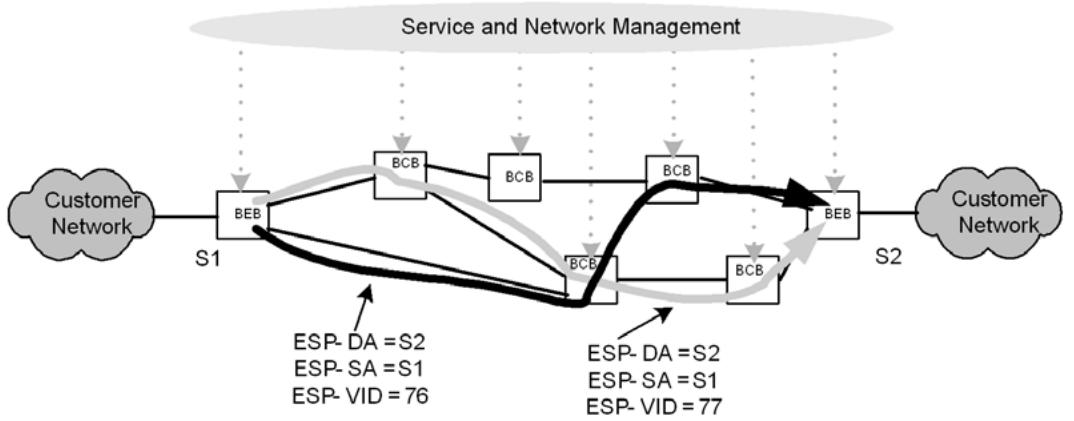
Figure 25-14—PBB-TE Region
If the ESP-VID range delegated is the 4094 possible values, then each CBP termination can sink $( 2 ^ { 1 2 } - 2 )$ routing trees, and the theoretical network maximum is about $2 ^ { 6 0 }$ ESPs. The number of ESPs supported by PBB-TE is constrained by issues related to coordinated management, independent management of groups of nodes or independent routing choices through parts of the path, limit through intermediate nodes, etc. In the cases where B-VLAN services are also offered by the same network, it is expected that most B-VIDs will be allocated to those B-VLANs since the use of the MAC addresses as part of the ESP identifiers allows at least $2 ^ { 4 8 }$ ESPs and the ESP-VIDs can be used mainly to provide path diversity.
25.10.2 ESP forwarding behavior
Forwarding of frames belonging to an ESP-VID differs from forwarding of frames belonging to B-VLANs in the following ways:
a) Frames associated with the ESP-VID are discarded when a Static Filtering Entry corresponding to the (ESP-DA, ESP-VID) is not found in the FDB [item b) in 5.4.5]. Proper operation of PBB-TE requires the provisioning of an FDB entry in each Bridge through which an ESP passes in order to specify the forwarding of traffic associated with that ESP. Such an entry may be absent due to a provisioning error. In the event of such an error, it is important that frames associated with the improperly configured ESP not be flooded, as PBB-TE would be violated if traffic intended for a particular ESP is sent on one or more other ESPs. Further, flooding based on the ESP-VID may result in unbounded looping and replication as the ESP-VID is not associated with a spanning tree. For this reason, frames associated with the ESP-VID are discarded when a Static Filtering Entry corresponding to the (ESP-DA, ESP-VID) is not found in the FDB. Such an ESP MAC address may represent an individual address, for which no more specific Static Filtering Entry exists or a group address, for which no more specific Static Filtering Entry exists (8.8.1).
b) MAC learning is not performed on receipt of a frame carrying an ESP-VID [item a) in 5.4.5]. Where ESPs have been correctly provisioned, learning would not interfere with the proper operation of Bridges, but in the presence of provisioning errors, learning may result in undesired behavior.
c) The active topology for the ESP-VIDs allocated to PBB-TE is no longer controlled by spanning tree protocols but by an external agent that is responsible for setting up the ESPs [item b) in 5.4.5].
NOTE 1—In a network supporting both VLAN (i.e., PBB) and ESP (PBB-TE) traffic, the establishment of an ESP and the policing of traffic at the ingress of the ESP are necessary but not sufficient conditions to ensure that traffic associated with an ESP receives the QoS intended by the network operator. The operator should ensure that the QoS requirements of an ESP are satisfied and that sufficient network capacity is available to accommodate broadcast-unknown traffic, spanning tree control traffic, and other traffic associated with VLAN usage.
Key properties of an ESP are as follows:
d) The ESP is identified at all points along its path by a single identifier <ESP-DA, ESP-SA, ESP-VID>.
e) The information referenced for forwarding <ESP-DA, ESP-VID> is contained within the ESP Identifier.
f) The information referenced for forwarding <ESP-DA, ESP-VID> does not change along the length of the ESP.
NOTE 2—The static and provisioned nature of an ESP provides support for traffic engineering. These properties of the ESP, together with policing and queuing functions supported by a Bridge (8.6) can provide per ESP QoS.
25.11 Transparent service interface
A PBBN may provide a transparent service interface for customer attachment. A transparent service interface is delivered on a CNP provided by a BEB as illustrated in Figure 25-15 and Figure 25-16. A transparent service interface may attach to a Provider Bridge, C-VLAN Bridge (5.9), MAC Bridge, router, or end-station. The service provided by this interface forwards all frames over the backbone on a single backbone service instance.
A transparent service interface does not recognize, add, remove, or modify either S-tags or C-tags on customer frames. It does not learn customer addresses, nor does it filter frames based on any MAC addresses except the TPMR component Reserved addresses listed in Table 8-3 and the management address of the TPMR component.
Figure 25-15 illustrates a customer network attached to a PBBN using a transparent service interface. The customer network uses End Stations, Customer Bridges, or Provider Bridges for connecting to the PBBN.
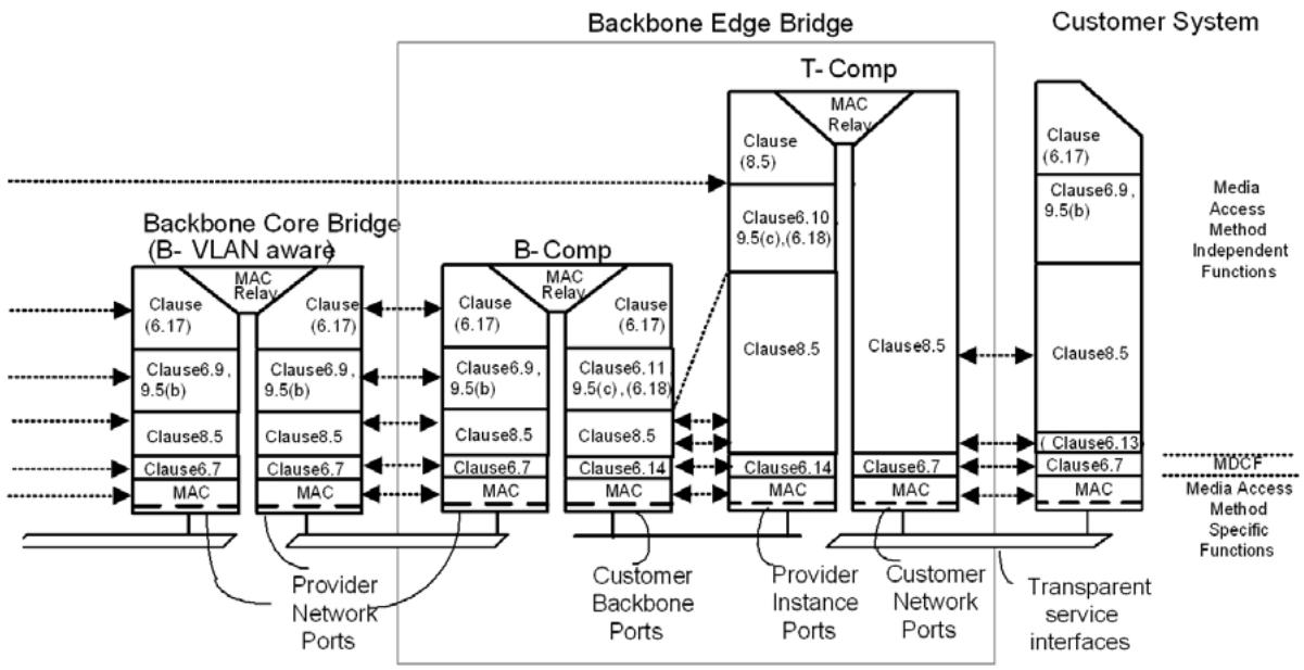
Figure 25-15—Transparent service interface
Figure 25-16 shows an example of equipment used to implement a transparent service interface. In this diagram a BEB is formed by connecting two T-components and a B-component. These connections may be over a backplane or over a LAN. A T-component supports a single transparent service interface associated with a CNP. A CNP is connected to a customer system (or network) using a LAN.
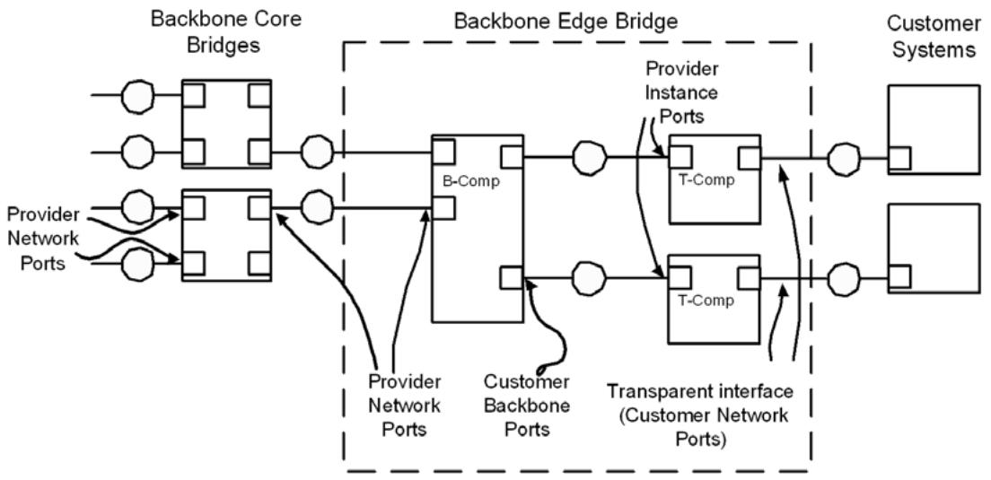
Figure 25-16—Transparent service interface equipment
26 Principles of Provider Backbone Bridged Network (PBBN) operation
This clause establishes the principles and a model of PBBN operation. It provides the context necessary to understand how the
a) Operation of individual Backbone Edge Bridges (BEBs) and Backbone Core Bridges (BCBs) (Clause 8, Clause 25);
b) Configuration and management of individual BEBs and BCBs (Clause 12);
c) Management of spanning tree and VLAN topologies within a PBBN (Clause 7, Clause 11, and Clause 13)
support, preserve, and maintain the quality of each of the instances of the MAC Service offered to the customers of the PBBN (Clause 6, Clause 25) including the following:
d) Independence of each service instance supported by a PBBN from other service instances (25.6).
e) Identification of service instances and backbone service instance within the PBBN (25.7, 8.8).
f) Maintenance of service availability in the event of the failure, restoration, removal, or insertion of LAN components connecting a customer network to a PBBN (Clause 6, Clause 11, Clause 13, 25.9).
A PBBN is a Virtual Bridged Network that comprises BEBs at the edge of the PBBN and BCBs at the core of the PBBN and attached LANs, under the administrative control of a single backbone provider. The principal elements of PBBN operation are those specified in Clause 16, as amended by this clause.
NOTE 1—The term PBBN is used exclusively to refer to networks configured and managed as specified by this clause and comprising only (a) BCBs and BEBs and (b) communications media and equipment providing the ISS (IEEE Std 802.1AC). While the requirements of Clause 25 are generally applicable to similar services, a generalized framework for all the network designs that could support these requirements, while useful in the context of other equipment and services, is outside the scope of this standard. This clause describes specific best practice for PBBNs to ensure that the requirements for Bridge functionality are clear. Conformance of a BEB implementation to this standard does not require that the implementation be used as specified in this clause; merely, that it is capable of being so used.
NOTE 2—Within a PBBN, an instance or instances of the MAC Service are reserved for the backbone provider’s own use to configure and manage the network. All frames associated with such service instances, and that are not confined to an individual LAN, are subject to service instance selection, segregation, and identification as specified in 26.1.
26.1 PBBN overview
The principal elements of PBBN operation comprise the following:
a) Encapsulation/de-encapsulation of service frames in B-MAC Frames (6.10).
b) Service instance segregation within a PBBN for service frames (25.6).
c) Service instance selection on ingress, and service instance identification on egress, for each customer frame (25.7).
d) Service access protection (25.9).
e) Resource allocation and configuration to provide service instance connectivity (26.3).
The following may also be included:
f) Management of customer end station address learning (26.4).
g) Prevention of connectivity loops formed through attached networks (26.5).
h) Scaling of PBBNs (26.6).
i) Provisioning of PBBN services (26.7).
j) Management of PBBN service connectivity (26.8).
26.2 PBBN example
An example PBBN is illustrated by the Figure 26-1. The example network is divided into three major areas: the customer equipment area, which is owned by the customer and is interfaced to the PBBN; the PBBN area, which is owned by the backbone provider and interconnects to the customer equipment and to other PBBNs; and the other PBBN area, which is owned by the same or other backbone providers and interconnects to multiple PBNs allowing the network to scale indefinitely.
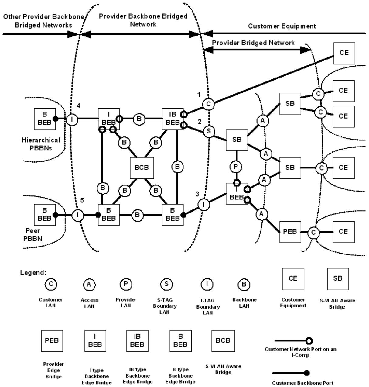
Figure 26-1—PBBN example
The interface between a BEB and a Provider Bridge is a CNP of an I-Component as specified in 6.10. The interfaces between BEBs and BCBs and between BCBs and BCBs are PNPs. In Figure 26-1, these interfaces are over LANs labeled S and B. The interfaces between B-BEB and I-BEBs, or between B-BEBs in different PBBNs, are over LANs labeled I. All exterior interfaces from a PBBN are over S, I, or C LANs; whereas, all interior interfaces within a PBBN are over B LANs. The S, I, and C LANs (exterior interfaces) are at the boundary between the PBBN and the attached customer networks.
The B LANs (interior interface) are backbone LANs, which interconnect all the PBBs within a PBBN.
Within the network example, BEBs, BCBs, and B LANs are secured so that only the backbone provider operating the PBBN can manage the reception, transmission, and relay of frames between BEBs and BCBs. The arbitrary physical network topology of the PBBN and the connectivity that it provides to support segregated instances of the MAC Service is designed and managed by the backbone provider to meet bandwidth and service availability requirements at the CBPs and PIPs. Application of the service instance ingress and egress rules at these Ports in support of service instance selection and identification ensures that frames cannot be transmitted or received on any backbone service instance by any customer’s equipment without prior agreement with the provider.
The active MSTP topology of the PBBN area is separated from the active topology of the customer equipment area. This is accomplished by isolating the MST BPDUs for each customer network from the PBBN at the BEBs that surround the perimeter of the PBBN. The BEBs also stop the propagation of MST BPDUs, used to support the active topology of the PBBN, into the Provider Bridged area. In Figure 26-1, Provider Bridge MST BPDUs are propagated over the A, P, C, and S LANs but not over the I or B LANs, while PBB MST BPDUs are propagated over the B LANs but not over the I, C, A, P, or S LANs.
For Port-based service interfaces, the entire C LAN is treated as a single instance of the MAC Service. The BEBs extend the C LAN over the backbone by mapping all service frames on a single backbone service instance identified by an I-SID. The I-SID used is provisioned by the provider operating the PBBN. The provider sets the I-SID on each BEB port attached to a C LAN that is part of the port based service. The BEBs encapsulate the service frames with an I-TAG, B-TAG, B-SA, and B-DA. During the encapsulation, any C-TAG delivered to the CNP is retained in the encapsulated frame as part of the SDU. The BEBs then map the frames onto a B-VLAN with its B-VID contained in the B-TAG and which interconnects the BEBs provisioned for the service. These new frames are transmitted over the B LANs by the BEBs and by the BCBs that carry the B-VLAN. Since the initial octets of the data conveyed in each backbone frame comprise an S-TAG, the frames may be forwarded by BCBs of the PBBN until they reach the next BEB where they might be de-encapsulated. During de-encapsulation, the B-DA, B-SA, B-TAG, and I-TAG are stripped. The C-DA and C-SA from the I-TAG will become the DA and SA transmitted to the receiving C LAN. If the encapsulated SDU contains a C-TAG, it becomes the outside tag as the frame is transmitted to the receiving C LAN.
For S-tagged service interfaces, each instance of MAC Service is carried over the S LANs on one or more S-VLANs. The BEBs preserve the S-VLAN over the backbone by mapping them onto an I-SID and in the case of S-VLAN bundling carrying the S-TAG. This operation is performed by the backbone provider operating the PBBN by configuring the VIP-ISID on each BEB attached to an S LAN. The BEB maps the S-VID to I-SID and encapsulates the original service frame with a new I-TAG, B-SA, and B-DA. The BEB then maps the frame onto a B-VLAN, which interconnects BEBs. This new frame is transmitted over the B LANs by the BEBs and by the BCBs. Since the initial octets of the data conveyed in each backbone frame comprise an S-TAG, the frames may be forwarded by BCBs of the PBBN until they reach the next BEB where they might be de-encapsulated.
For I-tagged service interfaces, each instance of MAC Service is identified by an I-SID value carried over the I LAN in an I-TAG. The BEB maps the frame onto a B-VLAN, which interconnects BEBs. This new frame is transmitted over the B LANs by the BEBs and by the BCBs. Since the initial octets of the data conveyed in each backbone frame comprise an S-TAG, the frames may be forwarded by BCBs of the PBBN until they reach the next BEB where they might be de-encapsulated.
B-MAC addresses are used to identify the destination BEB’s PIP. These B-MAC addresses are learned by each PBB as frames are exchanged over B-VLANs. To perform the encapsulation and de-encapsulation of service frames, BEBs use the connection identifier stored in the FDB (see 8.8) to correlate C-MAC addresses to B-MAC addresses. At startup, the BEBs have not learned the B-MAC or C-MAC addresses yet. When the B-MAC address is unknown, the BEB encapsulates the service frames using the Default Backbone Destination address. The same holds true for the service frames having a group or broadcast destination address. An individual B-DA is used for forwarding unknown or group frames when the service is point-to-point and where the far end individual address is known. Both the B-MAC and C-MAC addresses are learned by the provider BEB (see Clause 8).
Frames containing encapsulated service data are carried within the B-VLANs created over the PBBN. It is also possible to carry unencapsulated S-VLAN traffic in the PBBN core by allocating some of the PBBN VID space to S-VLANs. The B-VLAN determines the route that the frames will take and limits broadcasting within the backbone. The B-TAG is added to the frame at the CBP. The selection of B-VLAN used to form the B-TAG is determined by the configuration of the CBP Backbone Service Instance table. This table maps I-SIDs to B-VIDs and is created as part of service provisioning.
If a BEB’s PIP receives a B-MAC Frame whose B-SA is the same as the B-MAC address of the PIP, then a loop exists through the BEBs. Optionally, the BEB may use this condition for loop detection.
26.3 B-VLAN connectivity
The B-VLAN topology of each B-VLAN is established by the mechanisms introduced in 7.1 and Figure 7-1. The backbone provider can use and configure MSTP to provide a number of independent spanning tree active topologies and can assign each B-VLAN to one of these active topologies to best use the resources in the network. MVRP running in the context of each spanning tree active topology configures the extent of each B-VLAN to the subset of that active topology necessary to support connectivity between the customer points of attachment to the instance of MAC Service provided, and can reconfigure that connectivity as required if the spanning tree active topology changes.
The operation of MSTP within a Backbone Provider’s network is independent of the operation of any spanning tree protocol within attached provider or customer networks. This is achieved by removing all MST BPDUs received or to be transmitted at the service access interfaces.
The operation of MVRP within a PBBN is independent of the operation of any configuration protocol within attached customer networks. The Provider Bridge MVRP address (Table 8-1) is used as the destination address of all MRPDUs transmitted in support of the MVRP Application. Frames received by CBPs and addressed to the Customer Bridge MVRP address (Table 10-1) are subject to service instance selection and relay in the same way as service frames. The MVRP Administrative Control for each B-VLAN is either Registration Fixed (New Ignored) or Registration Forbidden on all CBPs, so no information is received from any BEB MVRPDU that has been erroneously transmitted by a customer system.
26.4 Backbone addressing
When customer frames enter a PBBN they are encapsulated by the addition of B-MAC addresses and the creation of an I-TAG. The encapsulation is the result of the actions of a PIP as specified in 6.10. The PIPs represent the endpoints of a backbone service instance, and the B-MAC addresses identify these endpoints. (More specifically the VIPs of the PIP represent the endpoints of a backbone service instance, and the combination of the B-MAC addresses and the I-SID identify these endpoints. Since the I-SID identifies which VIP of a PIP is the Backbone Service Instance endpoint, the B-MAC address need only identify the PIP. Therefore, all VIPs of a PIP can share the same MAC address.) This encapsulation ensures that only I-components learn C-MAC addresses, while B-components and Bridges in the PBBN core learn only B-MAC addresses.
The B-SA of an encapsulated frame identifies the PIP that performed the encapsulation and is referred to as the PIP MAC address. For a PIP that connects to an external LAN, this is the address of the PIP itself. For a PIP that has an internal connection to a CBP in the same BEB, this can be any address that results in delivering received I-tagged frames to the I-component, such as the Bridge address of that I-component. When the PIP MAC address is also used by CFM MPs instantiated on the PIP, there are additional constraints on the uniqueness of that address (26.4.3).
The B-DA of an encapsulated frame identifies the PIP(s) to which the frame should be delivered. The default value for the B-DA is the Backbone Service Instance Group address constructed by concatenating the three octet OUI shown in Table 26-1 with the three octet I-SID, and asserting the I/G bit in the first octet of the resultant value to signify a group MAC address. In a Backbone Service Instance Group address formed in this way, the OUI value is encoded in the first three octets of the address, with the most significant octet of the OUI encoded in the first octet, with the I/G bit (the LSB) set, and the least significant octet of the OUI encoded in the third octet; the most significant octet of the I-SID is encoded in the fourth octet of the address and the least significant octet of the I-SID in the sixth octet.
Table 26-1—Backbone Service Instance Group address OUI
<table><tr><td>Name</td><td>Value</td></tr><tr><td>IEEE 802.1Q Backbone Service Instance Group address OUI</td><td>00-1E-83</td></tr></table>
NOTE—Table 26-1 uses the Hexadecimal Representation specified in IEEE Std 802.
When the B-DA of a frame is the Backbone Service Instance Group address, the nominal behavior of the PBBN is to deliver the frame to all CBPs reachable within the B-VLAN to which the backbone service instance is mapped. Filtering based on I-SID by the egress CBP ensures that frames are not transmitted by CBPs that are not part of the backbone service instance. Flooding frames throughout the B-VLAN and filtering at egress provides the correct connectivity for the backbone service instance, but may result in inefficient use of PBBN resources. More efficient frame delivery can be achieved by configuring Static Filtering Entries in the backbone Bridges, or using MMRP to create MAC Address Registration Entries, that restrict the delivery to just the endpoints of the backbone service instance. More efficient delivery can also be achieved by learning individual B-MAC addresses at a PIP, and in some cases by configuring the CBPs to translate the Backbone Service Instance Group address.
26.4.1 Learning individual backbone addresses at a PIP
Individual backbone addresses are learned by means of the connection_identifier parameter generated by the PIP and stored in the FDB. For each received frame, the PIP includes in the EM_UNITDATA.indication a connection_identifier parameter that identifies the backbone source address of the frame. When the Icomponent Learning Process creates or updates a Dynamic Filtering Entry for a Customer Source MAC address (C-SA) of a frame received through a PIP, it stores the connection_identifier parameter of the EM_UNITDATA.indication for that frame. The connection_identifier parameter is included in the EM_UNITDATA.request for subsequent frames destined to that customer address. Within the PIP, the connection_identifier determines the individual backbone address associated with the customer address. This individual address is then used as the B-DA in place of the Backbone Service Instance Group address.
When a backbone service instance includes only two VIPs, it is possible to use a learned individual backbone address as the default B-DA instead of the Backbone Service Instance Group address. This is accomplished by configuring the AdminPointToPointMAC parameter for the VIP to ForceTrue, which results in the operPointToPointMAC parameter having a value of TRUE. In this case, the PIP copies the B-SA of frames received for that VIP (i.e., the individual MAC address of the peer PIP) to the Default Backbone Destination parameter of the VIP. Subsequent frames transmitted by the PIP on that backbone service instance will then use the individual MAC address of the peer PIP as the B-DA even if the C-DA is unknown or broadcast. Enabling the enhanced filtering criteria (8.7.2) on a VIP will prevent the Icomponent from creating Dynamic Filtering Entries for C-MAC addresses unnecessarily when the backbone service instance is point-to-point and the S-VLAN that maps to the backbone service instance has only the VIP and one CNP in its member set.
When the enableConnectionIdentifier of a VIP is set to FALSE, the connection_identifier is kept to a NULL value and correspondingly the B-DA used by frames associated with this VIP is always the Backbone Service Instance Group address.
26.4.2 Translating backbone destination addresses at a CBP
In some cases, when the B-DA is the Backbone Service Instance Group address it may be advantageous that the CBP translate this to a different address. Examples where such translation may be useful include the following:
a) When a backbone service instance has only two endpoints within a PBBN, the Backbone Service Instance Group address may be translated at the ingress CBP to the individual address of the egress CBP.
b) When multiple backbone service instances connect the same set of CBPs, the ingress CBP may translate the Backbone Service Instance Group address to a single group address chosen for the set of backbone service instances.
These translations can be accomplished by configuring the Default Backbone Destination parameter in the service instance table of the CBP (6.11). Whenever an ingress CBP is configured to translate the B-DA, the egress CBP must be configured to translate the B-DA back to the Backbone Service Instance Group address. This allows multiple PBBNs connected through Peer E-NNIs to use addresses local to each PBBN.
The CBP is also capable of translating the I-SID on frames entering and exiting the PBBN. This allows the values of the I-SID to be local to a PBBN. If the B-DA of the frame is the Backbone Service Instance Group address and the CBP translates the I-SID, the CBP will also reconstruct the Backbone Service Instance Group address using the new value of the I-SID.
26.4.3 Backbone addressing considerations for CFM MPs
Possible placement of CFM shims in a PIP and a CBP are shown in Figure 26-2. In the PIP, these include MPs to monitor backbone service instances (identified by I-SIDs) in the PBBN, as well as MPs to monitor service instances (identified by VIDs of S-VLANs) in the attached PBNs. In the CBP, these include MPs to monitor backbone service instance (identified by I-SIDs) in the PBBN, as well as MPs to monitor B-VLANs in the PBBN. All of these MPs are assigned individual addresses subject to the constraints specified in 19.4; however, there are additional considerations for the addresses used by MPs in PIPs and CBPs.
In a PIP, the individual address assigned to the backbone service instance-level MPs must be unique within the PBBN. The individual address assigned to the S-VLAN-level MPs must be unique within the set of PBNs interconnected by any backbone service instance supported by the PIP. Therefore, these two groups of MPs may use a common address that is globally unique; however, they may need distinct addresses if local addressing is used in the PBBN.
In the CBP, both the backbone service instance-level MPs and the B-VLAN-level MPs require an individual address that is unique within the PBBN. Therefore, these two groups may use a common address whether it is a global or local address.
26.5 Detection of connectivity loops through attached networks
The transmission and reception of MST BPDUs through CNPs will detect accidental direct connection of those ports. A backbone provider cannot rely on any customer network relaying such frames, and should develop a policy and mechanisms to deal with potential data loops that can arise if the attached customer systems do not operate their own instance or instances of a spanning tree protocol.
A bridged network can be redundantly attached to a PBBN by the means of several Layer Two Gateway Ports (13.40). By way of communication within their region and without any influence from the PBBN, those ports will provide connectivity to the PBBN through a single Layer Two Gateway Port, thus avoiding any bridging loop between the PBBN and the network.
NOTE 1—Use of the restrictedRole parameter at ingress ports ensures that receipt of BPDUs addressed to the Provider Bridge Group address cannot disrupt internal connectivity within the PBBN.
NOTE 2—Specification of PBBN policies, mechanisms, and heuristics used to detect or minimize the impact of data loops created by customer systems is not addressed by this standard. They can include, but are not limited to, bandwidth limitation, charging policies, detection of the repetitive movement of the apparent location of customer stations, and customer agreement to allow the use of PBBN loop detection protocols by not filtering the associated frames.
NOTE 3—A data loop is not the only possible cause of excess bandwidth consumption by a given customer of a PBBN, and the PBBN is usually required to meet service guarantees to other customers irrespective of the cause of the excess bandwidth demand. Data loops are not a unique threat to satisfactory overall network performance. Their distinct characteristic is consumption of discretionary bandwidth without benefiting any customer. The customer that creates the loop can suffer particularly serious network degradation or excess cost as the PBBN limits the total bandwidth consumed by that customer. It is therefore in the interests of each individual customer and the PBBN to raise service satisfaction by preventing and detecting loops.
26.6 Scaling of PBBs
For PBBN deployments, it is important to be able to interconnect PBBNs operated by different organizations. The interfaces between PBBNs are examples of the Metro Ethernet Forum (MEF) External Network to Network Interface (E-NNI) referred to in the MEF reference model (section 7.2 and Figure 3 of MEF 4). E-NNIs for interconnection of PBBNs can be further classified into two types: hierarchal interconnect and peer interconnect. Examples of hierarchal and peer interconnects are depicted in Figure 26-1 at the interfaces marked 4 and 5.
26.6.1 Hierarchal PBBNs
The hierarchal interconnect connects the PBBNs in a leveled hierarchy. In this interconnect model one PBBN acts as a second-level (n + 1) PBBN to a first-level (n) PBBN. This model allows scaling the number of services by additional hierarchal level. Each level of a hierarchal interconnect adds an additional encapsulation layer.
In the hierarchical model, the (n + 1)-level PBBN carries the n-level PBBN B-VLANs as services in the same manner that the first-level PBBN carries the customer S-VLANs as services. In this model an S-VLAN is presented to a level n PBBN for transport. The PBBN transports the S-VLAN as an instance of MAC Service within a B-VLAN generated by the n-level PBBN. The n-level PBBN is connected to an (n + 1)-level PBBN over a hierarchal E-NNI interface. The (n + 1)-level PBBN carries B-VLANs from the attached n-level PBBN as service instances in (n + 1)-level B-VLANs through the (n + 1)-level PBBN.
Since each hierarchal level requires an additional encapsulation, the nesting depth is limited by the maximum defined frame length for the MAC type used.
26.6.2 Peer PBBNs
The peer interconnect between PBBNs results in a flat service space that does not increase the encapsulation nesting depth. The network scales the number of services over the combined PBBNs by service localization. Further localization and scaling of services is supported by the I-SID filtering functions in addition to the optional I-SID translation functions of the CBP interfaces on each side of the peer E-NNI (6.11). Services that are limited in extent to a single PBBN do not consume any resources within the other connected PBBNs.
The peer interconnect will extend backbone service instances across the peer connected PBBNs. In the peer interconnect a service instance in PBBN A is connected to a service instance in PBBN B by the peer E-NNI between the PBBNs. The peer E-NNI is formed by an I-tagged Service Interface between two CBPs (6.11), one in each of the peer PBBNs. The I-SID used over the E-NNI must be agreed to mutually by both providers. At each end of the E-NNI the CBP may optionally translate the I-SID (and the B-DA if it is the default multicast address generated from the I-SID) used over the E-NNI to a new I-SID for use within the PBBN. The CBPs also map the I-SID to a B-VLAN within the PBBN, as no B-TAGs are transmitted across the peer interconnect.
26.7 Network management
Management of a PBB is directly under the control of the backbone provider. PBN customers shall not have access to managed objects related to elements of PBBs within the PBBN.
In SNMP management systems, this can be realized by implementing one management entity acting as an agent in the Provider Bridge and separating the management views that include customer networks information from the management views that include provider networks information using the mechanisms defined by the SNMP management framework in IETF RFC 3411.
26.8 CFM in PBBs
CFM (Clause 18 through Clause 22) may operate over LANs, C-VLANs, S-VLANs, B-VLANs, and backbone service instances identified by I-SIDs. CFM Maintenance domain Endpoints (MEPs) and Maintenance domain Intermediate Points (MIPs) may be inserted at any of the EISS service interfaces described by 6.9, 6.10, and 6.11, at the ISS service interface described in IEEE Std 802.1AC, and within the EISS and Backbone Service Instance Multiplex Entity described in 6.17 and 6.18.
Within a PBBN, the encapsulation performed by PIPs also encapsulates CFM frames sourced by customers attached to CNPs. Encapsulation of S-VLAN and C-VLAN CFM frames hides them from the PBBN enabling a new set of independent MD levels to be defined in the PBBN for CFM, which may be used for managing B-VLANs spanning between the B-components and BCBs of the PBBN, and over LANs that span between PBB ports. In addition, the backbone may support MAs per backbone service instance that are identified by I-SIDs and span between the PIPs and CBPs of I-components and B-components of the PBBN. A full set of eight maintenance levels exists within each PBBN for use by B-VLAN CFM frames. The Backbone Service Instance CFM frames may extend over a E-NNI, therefore providing eight levels of Backbone Service Instance CFM for the extended backbone, which includes all peer connected PBBNs. All eight levels of CFM frames generated in customer networks are carried over the backbone as encapsulated data and may be used by customer networks. Another eight maintenance levels exist for the LANs for which no frames are untagged. This may be the case for the PNP-PNP LAN links. The CFM stacks for the PIP and CBP are depicted in Figure 26-2. The stacks for the CNP and PNP are as depicted in 22.1.1.
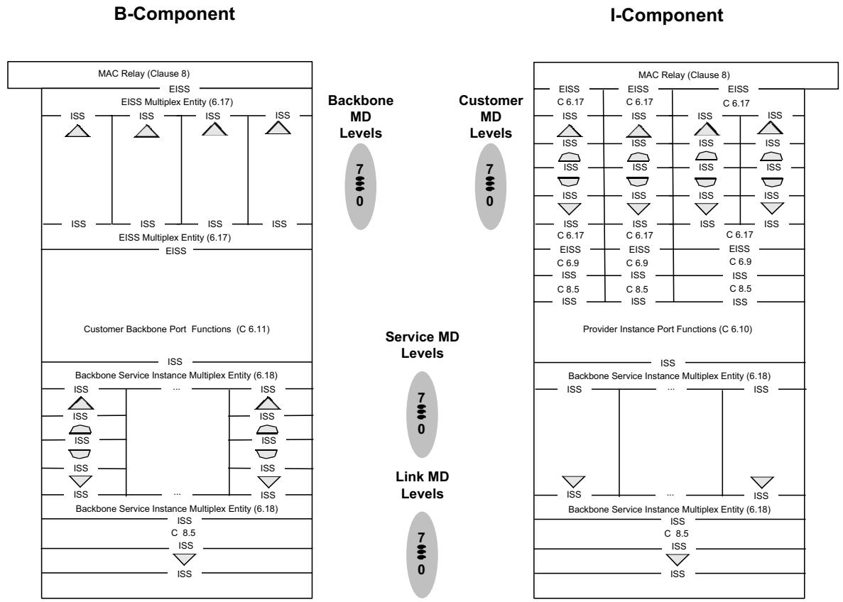
Figure 26-2—CFM shim model
Figure 26-3 and Figure 26-4 show possible MAs at the three types of PBBN service interfaces described in 25.3, 25.4, and 25.5, respectively. These three interfaces are depicted in Figure 26-1, where they are labeled 1, 2, and 3. Figure 26-5 and Figure 26-6 show possible MAs at the two types of PBBN E-NNI interfaces, which are described in 26.6.1 and 26.6.2, respectively. These two types of E-NNIs are depicted in Figure 26-1, where they are labeled 4 and 5. The MAs indicated in Figure 26-3 through Figure 26-6 are example MAs for each PBBN service interface type and PBBN E-NNI type. Typically not all these MAs would be supported within any given PBBN since some MAs illustrated provide redundant capabilities and since the selection of MAs will depend on the service-level agreements used for a particular service, on the operational environment of a particular PBBN and on the equipment used in the particular PBBN.
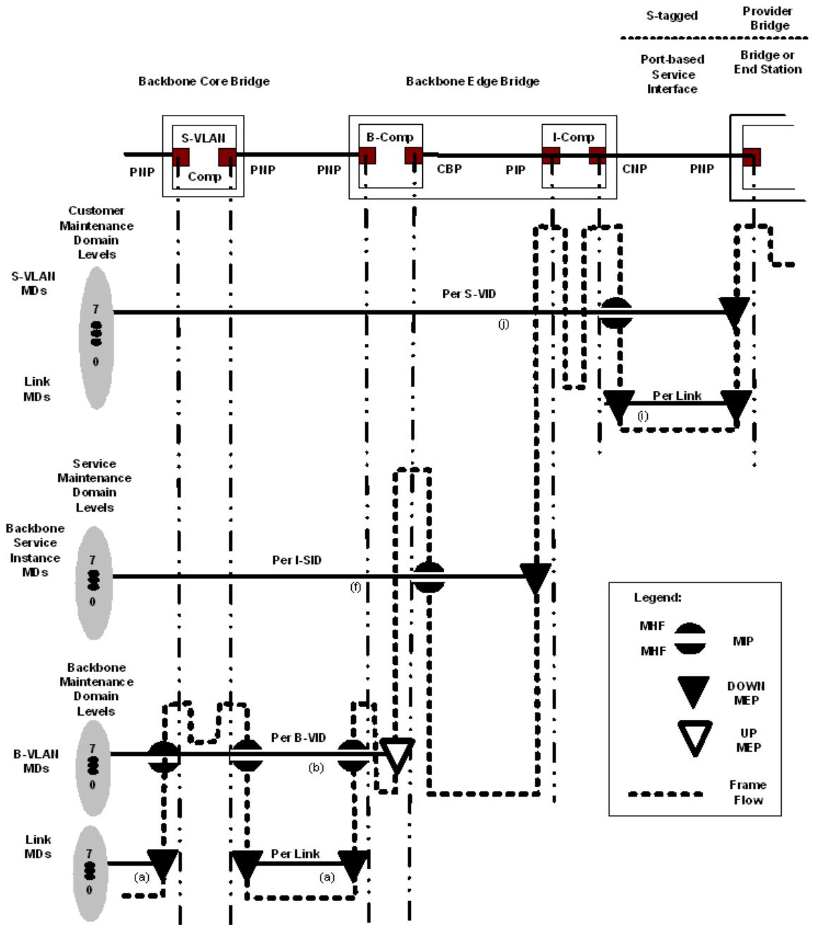
Figure 26-3—CFM example applied to a Port-based and S-tagged service interface
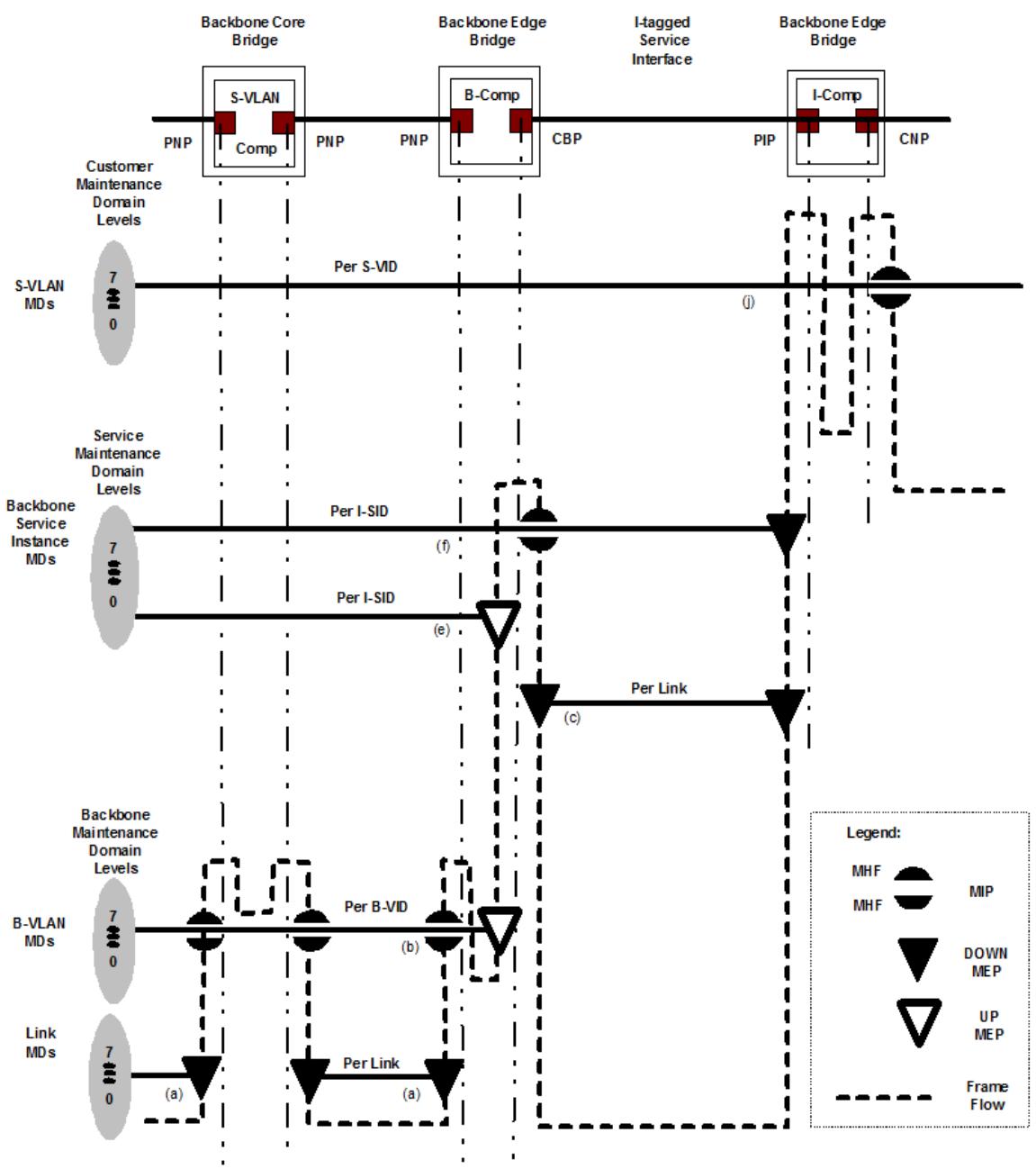
Figure 26-4—CFM example applied to an I-tagged Service Interface
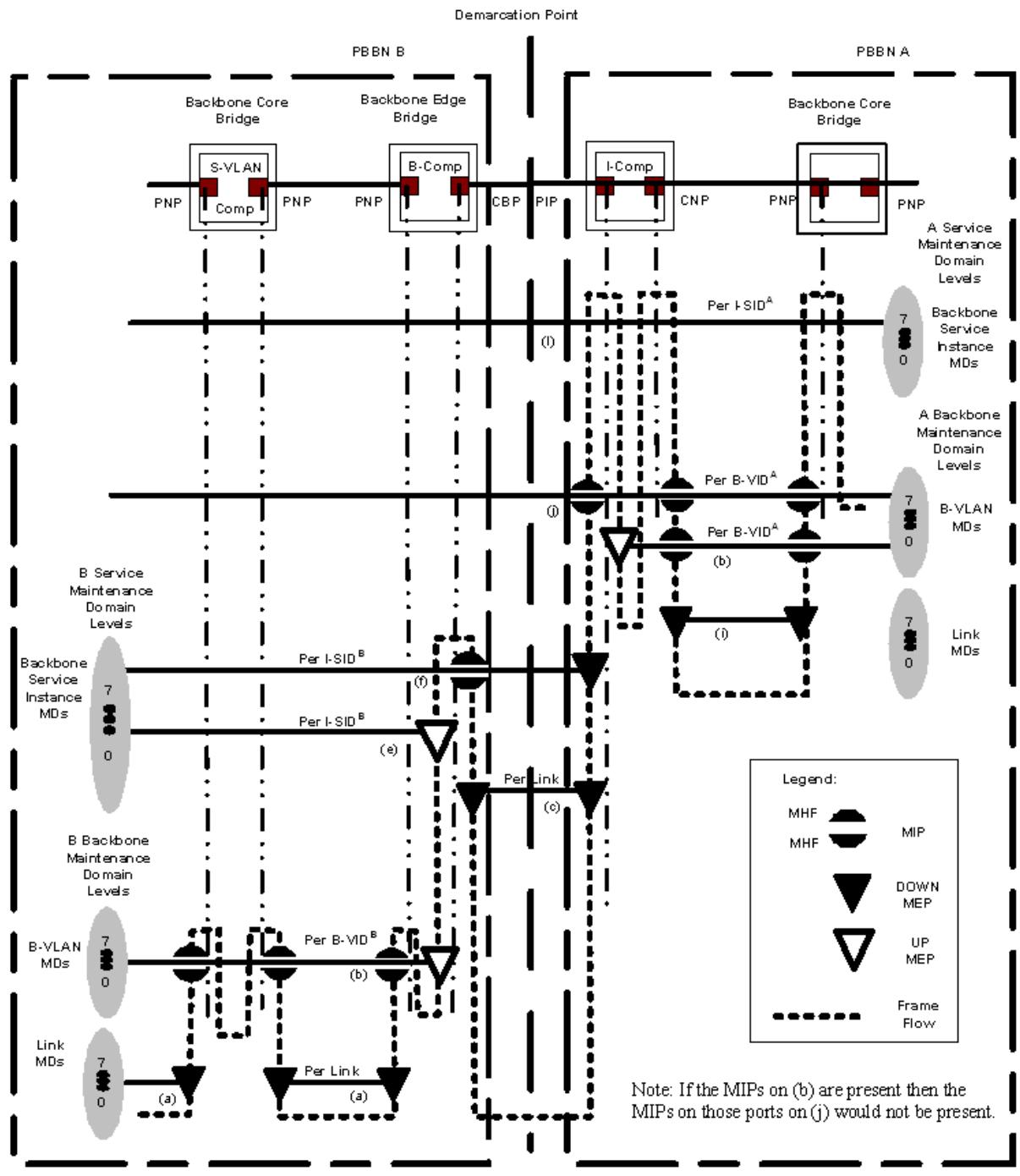
Figure 26-5—CFM example applied to a hierarchal E-NNI, CBP-PIP Demarc
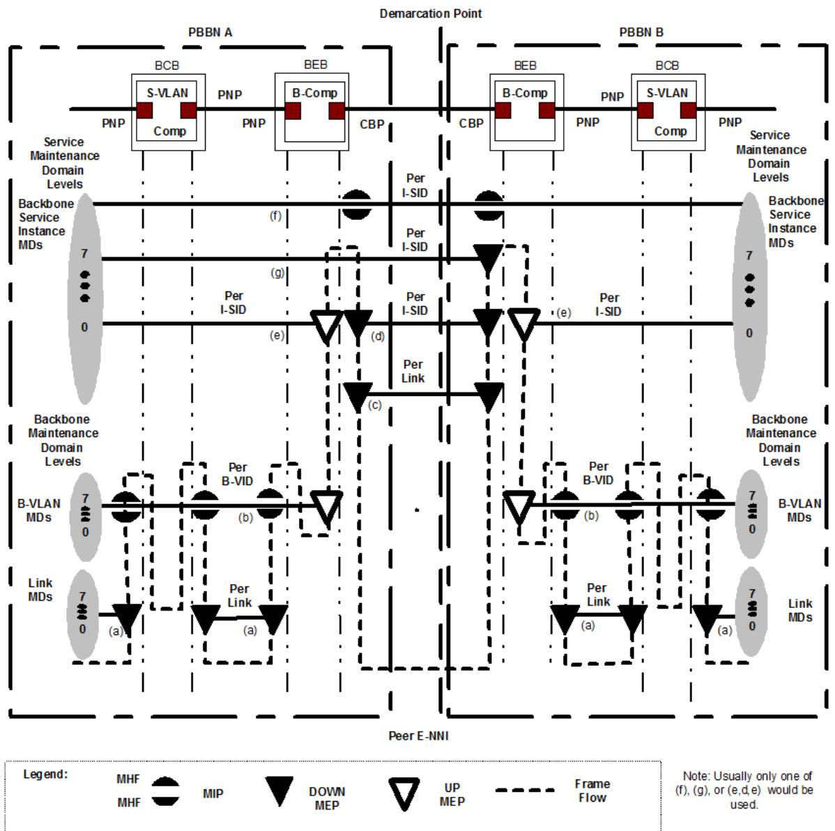
Figure 26-6—CFM example applied to a peer E-NNI, CBP-PIP
In these figures, four distinct categories of MAs are depicted. These are the S-VLAN and C-VLAN MAs, the Backbone Service Instance MAs, the B-VLAN MAs, and the LAN MAs. Each of these four classes of MAs is associated with independent sets of MDs introducing four independent sets of eight maintenance levels. The selection of which levels for each of these MDs to use in a particular network depends on the specific network implementation. The S-VLAN MAs are only visible within the I-component where customer frames are un-encapsulated. Customer CFM frames are encapsulated along with the other customer frames at the VIPs within the I-component. Once the S-VLAN CFM frames are encapsulated, they appear just like any data frame within the PBBN; therefore, they do not activate any CFM functions within the PBBN past the VIPs. The Backbone Service Instance CFM frames may optionally be generated at the Backbone Service Instance Multiplex Entity within the PIP or CBP. These CFM frames are only visible within the PBBN where the I-TAG is being processed, that is at the CBP and at the PIP. Each Backbone Service Instance MD may be assigned to one of eight maintenance levels. Since the Backbone Service
Instance CFM maintenance domain may extend over E-NNI boundaries, these eight levels extend over all interconnected PBBNs until they are terminated at a VIP. B-VLAN MAs manage the B-VLANs within a single PBBN. The B-VLAN MDs have a new set of eight maintenance levels, which are separate for each PBBN and never extend out of the PBBN. Finally, the LAN links within a PBBN (PIP to CBP, PNP to PNP), between two PBBNs (CBP to CBP, PIP to CBP) and entering/egressing the PBBN (to/from CNP) may optionally be monitored by LAN link MAs, generated/terminated within the PIP, CBP, PNP, and CNP. LAN link MAs are typically confined to the LAN link.
26.8.1 CFM over Port-based and S-tagged service interfaces
Figure 26-3 shows example MAs for the Port-based or S-tagged service interface described in 25.3 and 25.4 and depicted in Figure 26-1 labeled 1 and 2.
MAs (a) and (b) illustrated in Figure 26-3 through Figure 26-6 are used to monitor the PBBN core. Each PBBN has an independent backbone MD-level space. MAs (a) and (b) are assigned Backbone Maintenance Levels from the backbone MD-level space of their PBBN in the same manner used to assign S-VLAN MAs described in Clause 22. The MAs (a) are used to monitor each individual LAN that interconnects PNPs. The MAs (b) monitor specific B-VLANs. The B-VLAN monitoring, illustrated in the example, begins at the up MEP located at the top of the CBP. A given B-VLAN may exit a B-component on multiple PNPs, each of which may have a MIP on MA (b) if desired.
MAs (i) and (j) illustrated in Figure 26-3 through Figure 26-6 are two possible customer MAs. Attached customers have an independent customer MD-level space. MAs (i) and (j) are assigned Customer Maintenance Domain Levels from their customer MD-level space in the manner used for S-VLAN MAs described in Clause 22. The MAs (i) monitor the links between the customer equipment and the CNP or the PBBN. At the Port-based or the S-tagged service interface, MAs (i) may be terminated by the provider by an MEP at the CNP and used to monitor the customer’s access link. The MAs (j) monitor the service instance from the customer over the PBBN. MAs (j) extend between all the customer attachments of the extended PBBN, passing through any PBBN E-NNI interfaces. At the VIPs located at the edge of the extended PBBN, the CFM frames for MA(j) will be mapped to/from an I-SID and carried over the extended PBBN as encapsulated frames. These CFM frames are encapsulated by the PBBN in the same manner as data frames. The encapsulation makes them invisible to any MPs within the extended PBBN.
In the case of a Port-based service interface, the MA(j) CFM frames are untagged or C-tagged over the interface formed between the CNP and the customer equipment. In this case, the MA(j) CFM frames have an S-VID assigned from the PVID at the CNP, which will be carried to the VIP within the I-component. In the case of an S-tagged service interface, the MA(j) CFM frames are untagged, C-tagged, or S-tagged over the interface formed between the CNP and the customer equipment. In this case, the MA(j) CFM frames have the S-VID carried over the service interface or, if the CFM frame is not S-tagged, it will have an S-VID assigned from the PVID of the CNP.
MA (f) depicted in Figure 26-3 through Figure 26-6 is used for backbone service instance management. MAs (f) are within the Backbone Service Instance MD-level space, which is shared over the entire extended PBBN. MAs (f) are assigned Service Maintenance Domain Levels from this Backbone Service Instance MD-level space. The MEPs for MA(f) are formed at the PIP within the Backbone Service Instance Multiplex Entity (6.18) as seen in Figure 26-2. MA(f) may have MIPs located in the CBP also formed by a Backbone Service Instance Multiplex Entity as depicted in Figure 26-2.
26.8.2 CFM over I-tagged Service Interfaces
Figure 26-4 shows possible MAs for the I-tagged service interface described in 25.5 and depicted in Figure 26-1 labeled 3. The MAs (a) and (b) in Figure 26-4 are used for PBBN core monitoring as described in 26.8.1.
MAs (c) in Figure 26-4, Figure 26-5, and Figure 26-6 are used to monitor the link between the PIP and CBP. The MAs (c) CFM frames are unique among the other CFM frames because they are transmitted without an I-TAG over the CBP to PIP LAN.
MAs (f) depicted in Figure 26-4 are used for service management as described in 26.8.1. In an I-tagged service interface, MAs (f) have an MEP in the customer network located at the Backbone Service Instance Multiplex Entities (6.18) of the customer PIP and may have MIP within the extended provider network located at the Backbone Service Instance Multiplex Entities of the CBPs. The provider may use MAs (e) to monitor each service instance by placing a MEP at the Backbone Service Instance Multiplex Entities of the CBP. The backbone service instance-level space is shared between the customer and provider who must agree on the levels used for provider and customer Backbone Service Instance CFM messages.
Customer S-VLAN MAs (j) are encapsulated by the customer equipment and are indistinguishable from data within the PBBN.
26.8.3 CFM over hierarchal E-NNI
Figure 26-5 shows possible MAs for the hierarchal E-NNI described in 26.6.1. In Figure 26-1 the hierarchal E-NNI labeled 4 depicts an E-NNI with the demarcation point between the CBP and PIP. Example MAs for a hierarchal E-NNI with demarcation between CBP and PIP are illustrated in Figure 26-5. The MAs (a) and (b) in Figure 26-5 are used for PBBN core monitoring as described in 26.8.1.
The operation of the backbone service instance and LAN MAs (f), (e), and (c) are as described in 26.8.2. Since each PBBN-A B-VLAN MA (j) is mapped into a PBBN-B backbone service instance monitored by MAs (f) and/or (e) the MAs (f) and (e) may be used to monitor the extended B-VLAN from PBBN-A.
MAs (j) are not visible to PBBN-B as described in 26.8.2. The per PBBN-A Backbone Service Instance MAs (l) illustrated in Figure 26-5 are never visible to PBBN-B since they are encapsulated along with the B-VLAN.
26.8.4 CFM over peer E-NNI
Figure 26-6 shows possible MAs for the peer E-NNI described in 26.6.2 and depicted in Figure 26-1 labeled 5. The MAs (a) and (b) in Figure 26-6 are used for PBBN core monitoring as described in 26.8.1. The LAN MAs (c) and Backbone Service Instance MAs (e) and (f) in Figure 26-6 are as described in 26.8.2.
The MAs (f), (g), (d), and (c) extend over the demarcation point between PBBN-A and PBBN-B, while the MAs (e) are within PBBN-A and PBBN-B and do not extend over the demarcation point. The MA (f) is a Backbone Service Instance MA that extends through both PBBN-A and PBBN-B providing monitoring for the service from VIP to VIP. MAs (f) may have a MIP on each side of the demarcation point to allow isolation of a fault to an individual PBBN. The MAs (g) also are Backbone Service Instance MAs that extend over the demarcation point. MAs (g) are launched by PBBN-B at the CBP facing the E-NNI rather than at the service originating VIP and extend to the far edge of PBBN-A. MAs (g) may be used by PBBN-B to monitor the backbone service instance over PBBN-A, but only provides information to PBBN-A on the operation of the backbone service instance over the demarcation point to PBBN-B. The MA (d) is a Backbone Service Instance MA that monitors the service over the demarcation point, but does not provide any monitoring deeper in PBBN-A or PBBN-B. MAs (e) provide internal monitoring of the backbone service instance within PBBN-A and PBBN-B, respectively.
26.9 CFM in a PBB-TE Region
CFM as specified in Clause 18 through Clause 22, provides capabilities useful in detecting, isolating, and reporting connectivity faults in VID-based service instances, backbone service instances, TESIs, and Infrastructure Segments. The list of features that are specifically related to TESIs and Infrastructure Segments is summarized here.
NOTE—MIP function is not supported for an Infrastructure Segment MA. Loopback is supported on Infrastructure Segment MEPs. It is not useful to apply the Linktrace operation to an Infrastructure Segment MA. No extension is made to the Loopback or Linktrace operations supporting their use for an Infrastructure Segment MA. This does not preclude the use of MIPs associated with a PBB-TE MA.
In particular, this subclause summarizes PBB-TE considerations related to the following:
a) Addressing PBB-TE MEPs (26.9.1)
b) TESI identification (26.9.2)
c) PBB-TE MEP placement in a Bridge Port (26.9.3)
d) PBB-TE MIP placement in a Bridge Port (26.9.4)
e) TESI Maintenance Domains (26.9.5)
f) PBB-TE enhancements of the CFM protocols (26.9.6)
g) Addressing Infrastructure Segment MEPs (26.9.7)
h) Infrastructure Segment identification (26.9.8)
i) Infrastructure Segment MEP placement in a Bridge Port (26.9.9)
j) Infrastructure Segment Maintenance Domains (26.9.10)
k) IPS extensions to Continuty Check operation (26.9.11)
26.9.1 Addressing PBB-TE MEPs
The configuration of an MA requires a parameter (or a list of parameters) that associates it with the monitored service. A TESI is identified by the list of ESPs supporting it. Correspondingly, the configuration of a PBB-TE MA, requires the list of the monitored TESI’s ESPs, each identified by the 3-tuple <ESP-DA, ESP-SA, ESP-VID> or collectively by the TE-SID (12.14.5.3.2).
The MEPs related to a TESI require the same set of parameters as a VID-based MEP requires, with the following changes:
a) The Primary VID is not writable but is always set to the value of the ESP-VID parameter that corresponds to the MA’s ESP that has the MEP’s MAC address in its ESP-SA field [item d) in 12.14.7.1.3, 20.9.7];
b) The MAC address of the MEP is the MAC address of the CBP upon which the MEP is operating [item i) in 12.14.7.1.3].
26.9.2 TESI identification
In contrast to VID-based services where the vlan_identifier is used to identify the service, independent ESPs could have the same VID value in their ESP-VID field if some other parameters in their identifying 3-tuples are different. Figure 26-7 depicts such a case where the two ESPs are distinguished by their source addresses. The TESI Multiplex Entity (6.19) allows shims defined for PBB-TE to be instantiated per TESI at a SAP that supports multiple TESIs.
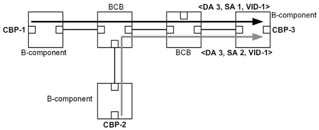
Figure 26-7—Independent ESPs using the same ESP-DAs and ESP-VIDs
26.9.3 PBB-TE MEP placement in a Bridge Port
PBB-TE MEPs are always Up MEPs and can only be placed on CBPs as these correspond to the demarcation points of the ESPs supporting the PBB-TE service. The PBB-TE MEPs are placed between the Frame filtering entity (8.6.3) and the Port filtering entities (8.6.1, 8.6.2, and 8.6.4) in the ESP-VID space identified by the EISS Multiplex Entity (6.17). Since the ESP MAC addresses can be reused by different ESPs, the PBB-TE MEPs need to be further differentiated by the TESI Multiplex Entity (6.19). In principle, separately for each TESI, there can be from zero to eight Up MEPs, ordered by increasing MD Level, from Frame filtering toward Port filtering, even though not more than one MD Level is expected for PBB-TE MAs. Figure 26-8 depicts an example of PBB-TE MEPs on a CBP.
26.9.4 PBB-TE MIP placement in a Bridge Port
PBB-TE MIPs creation is based on the algorithm described in 22.2.3. PBB-TE MIPs are created per identified ESP-VIDs on PNPs. Figure 22-9 depicts an example of a pair of PBB-TE MHFs on a PNP.
26.9.5 TESI Maintenance Domains
A PBB that is capable of providing TESIs supports a new set of TESI MDs in addition to those described in 26.8. In particular the CFM stacks in Figure 26-2 will need to have TESI MD levels in parallel to the depicted Backbone MD levels for CBPs initiating TESIs while TESI MDs will have to be present in parallel to the Backbone MD levels depicted in Figure 26-3.
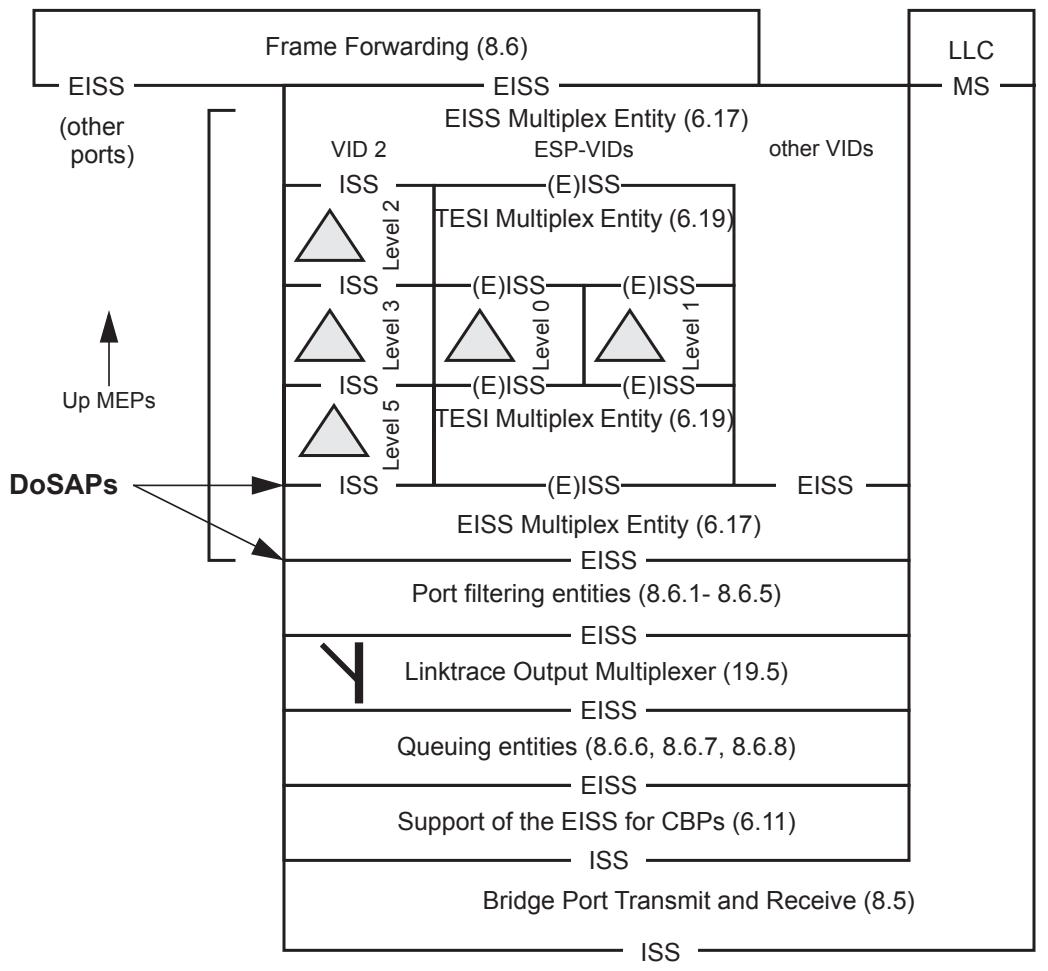
Figure 26-8—PBB-TE MEP placement in a CBP
26.9.6 PBB-TE enhancements of the CFM protocols
26.9.6.1 Continuity Check protocol in a PBB-TE MA
The Continuity Check protocol is described in 20.1 and the corresponding state machines in Clause 20. The only enhancement required by the PBB-TE MA is in the procedure that is responsible for constructing and transmitting a CCM (20.11.1):
a) The destination_address parameter is set to the MAC address indicated by the value of the ESP-DA field of the ESP having as ESP-SA the MAC address of the MEP emitting the CCM.
PBB-TE MAs may also implement the following enhancements to the Continuity Check protocol:
b) The procedure MEPprocessEqualCCM() on PBB-TE MEPs does not include the check of the MAID on received CCMs [item b) in 20.17.1].
c) PBB-TE MEP’s may
1) Set the Traffic field (21.6.1.4) bit on transmitted CCMs based on information from the Backbone Service Instance table associated with the CBP upon which the MEP is configured. In particular, the procedure xmitCCM() (20.11.1) is performing the additional action to fill the Traffic field with the presentTraffic variable (20.9.8); and
2) Check the Traffic field bit on received CCMs (20.16.13); and
3) Implement the MEP Mismatch state machines (20.26).
All other Continuity Check processes are the same as those for a VID-based MA.
26.9.6.2 Loopback protocol in a PBB-TE MA
The Loopback protocol is described in 20.2 and the corresponding state machines in Clause 20. The enhancements required by the PBB-TE MA are summarized below:
a) The LBMs transmitted by a MEP associated with a PBB-TE MA use as the destination_address parameter, the MAC address indicated by the value of the ESP-DA field of the MA’s ESP that has the MEP’s MAC address indicated in its ESP-SA field [item a) in 20.31.1]. To enable MIPs to selectively intercept LBMs that are targeting them, the PBB-TE MIP TLV (21.7.5) is inserted as the first TLV [item f) in 20.31.1] in an LBM. The PBB-TE MIP TLV is not included if the LBM destination address in 12.14.7.3.2 is associated with any of the values in the ESP-DA field of the monitored MA’s ESPs. The format of the PBB-TE MIP TLV is described in 21.7.5 and is constructed as follows:
1) The MIP MAC address field contains the MAC address of the MIP to which the LBM is targeted [item b) in 12.14.7.3.2];
2) The Reverse VID field contains the parameter provided in item f) in 12.14.7.3.2, which it uses as the vlan_identifier in the replied LBR;
3) The Reverse MAC field is only included if the MEP is associated with a point-to-multipoint TESI. If the MEP is the root MEP, the Reverse MAC field contains the ESP-SA value of any of the point-to-point ESPs in the TESI. If the MEP is a leaf MEP, the Reverse MAC field contains the ESP-DA of the point-to-multipoint ESP in the TESI.
b) LBMs received by PBB-TE MEPs are not processed and are discarded if the received LBM carries a PBB-TE MIP TLV. A PBB-TE MHF forwards all received LBMs except those carrying a PBB-TE MIP TLV containing in their MIP MAC address field the MAC address of the MIP associated with that PBB-TE MHF [item f) in 20.28.1].
c) The destination_address parameter used by LBRs transmitted by PBB-TE MEPs is the value of the ESP-DA of the MA’s ESP that has the MEP’s own address in its ESP-SA field. In the case of a PBB-TE MHF, the destination_address parameter for the transmitted LBR is
1) The value carried in the Reverse MAC field contained in the PBB-TE MIP TLV of the received LBM, if this is a group MAC address; otherwise,
2) The value of the source_address of the received LBM.
d) The source_address of LBRs transmitted by PBB-TE MHFs is set to
1) The destination_address of the received LBM if this destination address is an individual MAC address; otherwise,
2) The value carried in the Reverse MAC field contained in the PBB-TE MIP TLV if the received LBM’s destination address is a group MAC address.
e) The vlan_identifier used by LBRs transmitted by PBB-TE MEPs is set to the value of its Primary VID [item d) in 12.14.7.1.3]. The vlan_identifier used by LBRs transmitted by PBB-TE MHFs is set to the value carried in the Reverse VID field contained in the PBB-TE MIP TLV of the received LBM.
All other Loopback processes are the same as those for a VID-based MA.
26.9.6.3 Linktrace protocol in a PBB-TE MA
The Linktrace protocol is described in 20.3 and the corresponding state machines in Clause 20. The enhancements required by the PBB-TE MA are summarized as follows:
a) The LTMs transmitted by a MEP associated with a PBB-TE MA use as the destination_address parameter, the MAC address indicated by the value of the ESP-DA field of the MA’s ESP that has the MEP’s MAC address indicated in its ESP-SA field [item a) in 20.42.1]. LTMs carry the PBB-TE MIP TLV constructed as follows:
1) The MIP MAC address field is null;
2) The Reverse VID field contains the parameter provided in item e) in 12.14.7.4.2, which is used as the vlan_identifier of the replied LTR;
3) The Reverse MAC field is only included if the MEP is associated with a point-to-multipoint TESI. If the MEP is the root MEP, the Reverse MAC field contains the ESP-SA value of any of the point-to-point ESPs in the TESI. If the MEP is a leaf MEP, the Reverse MAC field contains the ESP-DA of the point-to-multipoint ESP in TESI.
b) No special destination_address validation tests are performed by the ProcessLTM() procedure in the case of PBB-TE MAs [item c) in 20.47.1].
c) The process to identify a possible egress port by an intermediate device that implements a MIP associated with a PBB-TE MA, queries the FDB of the corresponding Bridge, using the destination_address, and the vlan_identifier of the LTM as the parameters for the lookup (20.47.1.2). The LTMs can be further forwarded by PBB-TE MIPs even if the lookup identifies more than one Egress port.
d) Finally an LTR issued by a PBB-TE MP
Uses as destination_address: the value carried in the Reverse MAC field contained in the PBB-TE MIP TLV of the received LTM, if this is a group MAC address; otherwise, the source_address of the received LTM [item a) in 20.47.4].
2) Uses as source_address: its MAC address if the LTR is issued by a PBB-TE MEP; otherwise, the destination_address of the received LTM if this is destination address is an individual MAC address; otherwise, the value carried in the Reverse MAC field contained in the PBB-TE MIP TLV of the received LTM [item b) in 20.47.4].
3) Sets the vlan_identifier parameter to the value carried in the Reverse VID field contained in the PBB-TE MIP TLV of the received LTM [item c) in 20.47.4].
All other Linktrace processes are the same as those for a VID-based MA.
26.9.7 Addressing Infrastructure Segment MEPs
The configuration of an Infrastructure Segment MA requires a parameter identifying the associated Infrastructure Segment. An Infrastructure Segment is composed of a pair of counterdirectional and co-routed Segment Monitoring Paths (SMPs) (26.11.1). Each SMP is identified by an SMP Identifier (SMP-ID). Thus, an Infrastructure Segment is identified by a pair of SMP-IDs that is known as an Infrastructure Segment Identifier (SEG-ID). The SEG-ID is specified on configuration of the associated Infrastructure Segment MA (12.14.5.3.2).
A MEP associated with an Infrastructure Segment requires the same set of parameters required by a VIDbased MEP, with the following changes:
a) The Primary VID is not writable but is always set to the value of the SMP-VID parameter that corresponds to the MA’s SMP that has the MEP’s MAC address in its SMP-SA field (12.14.7.1.3 d));
b) The MAC address of the MEP is the MAC address of the PNP upon which the MEP is operating (12.14.2.1.2 i)).
26.9.8 Infrastructure Segment identification
Two SMPs are distinct if their corresponding SMP-ID values (3-tuples) differ in at least one parameter. Thus, independent Infrastructure Segments can be associated with SMPs having identical values of SMP-DA and SMP-VID. Figure 26-7 depicts a case in which two SMPs, having identical values of SMP-DA and SMP-VID, are distinguished by their SMP-SA values. The Infrastructure Segment Multiplex Entity (6.21) allows shims defined for PBB-TE IPS to be instantiated per Infrastructure Segment at a SAP that supports multiple Infrastructure Segments.
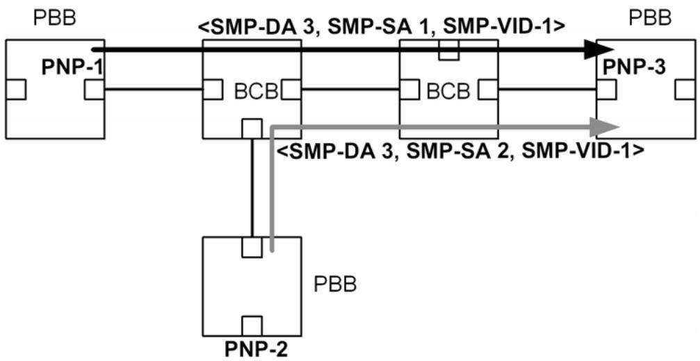
Figure 26-9—Independent Infrastructure Segments distinguished by SMP-SA
26.9.9 Infrastructure Segment MEP placement in a Bridge Port
Infrastructure Segment MEPs are always Down MEPs and are placed only on PNPs as these correspond to the demarcation points of the Infrastructure Segment. The Infrastructure Segment MEPs are placed between the Port filtering entities (8.6.1, 8.6.2, and 8.6.4) and the Queuing entities (8.6.5, 8.6.6, 8.6.7, and 8.6.8) in the SMP-VID space identified by the EISS Multiplex Entity (6.17). Since the Infrastructure Segment MAC addresses can be reused by different Infrastructure Segments, the Infrastructure Segment MEPs need to be further differentiated by the Infrastructure Segment Multiplex Entity (6.21). In principle, separately for each Infrastructure Segment, there can be from zero to eight Down MEPs, ordered by increasing MD Level, from Frame filtering towards Port filtering, even though not more than one MD Level is expected for Infrastructure Segment MAs. Figure 26-8 depicts an example of Infrastructure Segment MEPs on a PNP.
26.9.10 Infrastructure Segment Maintenance Domains
A PBB deploying IPS specifies a set of Infrastructure Segment MDs independent of those described in 26.8 and 26.9.5. In particular the CFM stacks in Figure 26-2 have Infrastructure Segment MD levels in parallel to the depicted Backbone MD levels for Ports instantiating Infrastructure Segments while Infrastructure Segment MDs will be present in parallel to the Backbone MD levels depicted in Figure 26-3.
26.9.11 IPS extensions to Continuity Check operation
The Continuity Check protocol is described in 20.1 and the corresponding state machines in Clause 20. The only enhancement required by the Infrastructure Segment MA is in the procedure that is responsible for constructing and transmitting a CCM (20.11.1):
a) The destination_address parameter is set to the MAC address indicated by the value of the SMP-DA field of the SMP-ID having as SMP-SA the MAC address of the MEP emitting the CCM.
All other Continuity Check processes are the same as those for a VID-based MA.
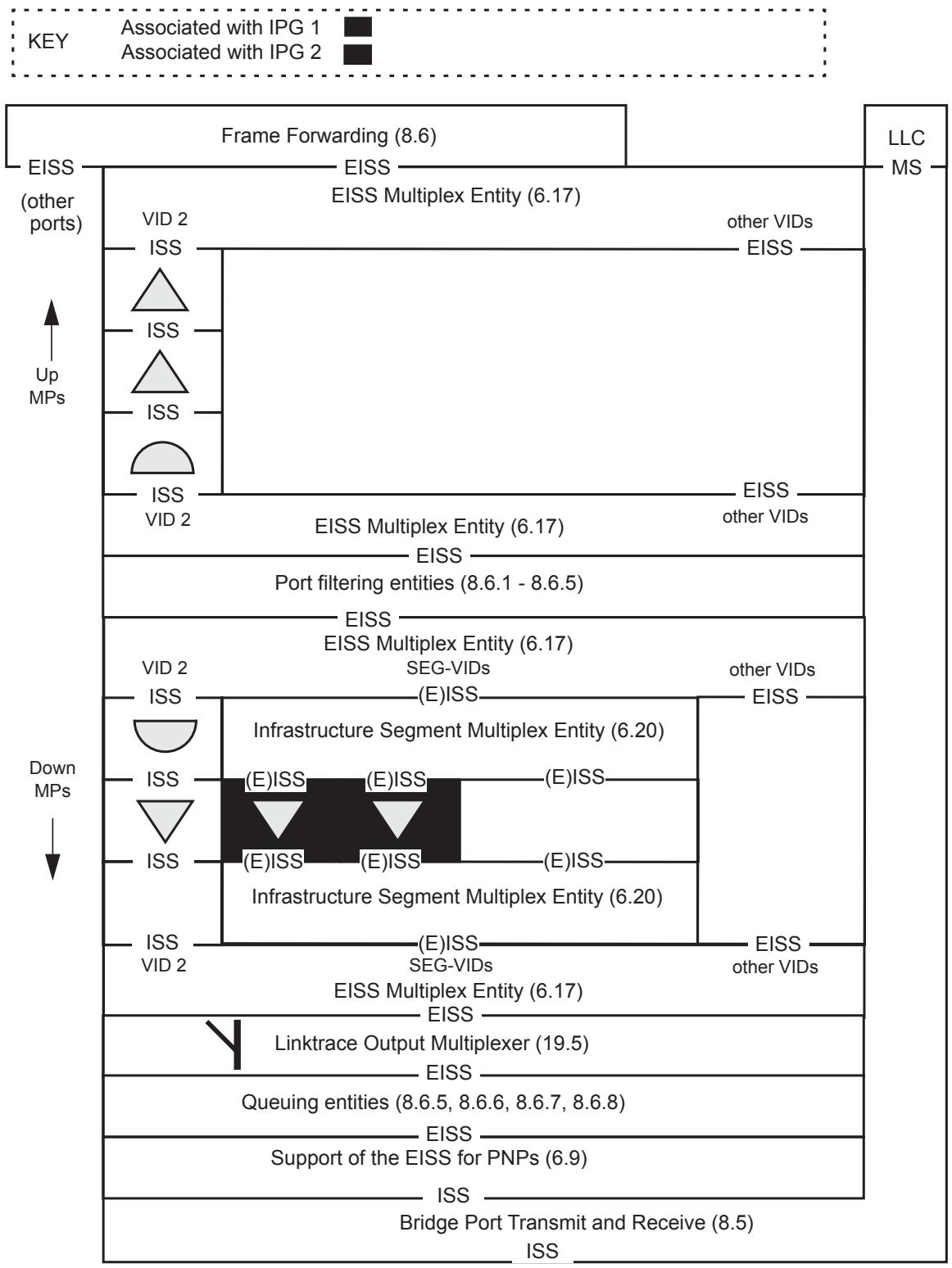
Figure 26-10—Infrastructure Segment MEP placement in a PNP
26.10 Protection switching for point-to-point TESIs
26.10.1 Introduction
In contrast to PBB, spanning tree protocols and broadcasting/flooding are not used in PBB-TE. FDBs are populated using a network management system or a control plane, allowing ESPs to be engineered and provisioned across the network. PBB-TE provides end-to-end linear protection for point-to-point TESIs, where a dedicated protection point-to-point TESI is established for one particular working point-to-point TESI, and the traffic is automatically switched from the working TESI to the protection TESI when a failure occurs on the working entity. The protection entity is preestablished, ensuring the availability of those resources when a defect is detected on the working entity, and allowing for a corresponding sub-50 ms switchover.
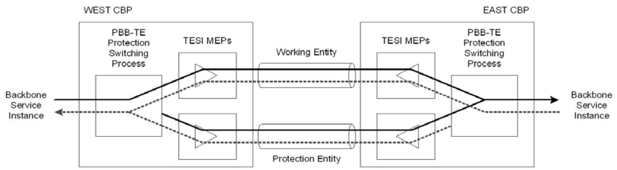
Figure 26-11—Protection switching architecture
Figure 26-11 depicts the essential elements of the PBB-TE protection scheme and its arrangement. In this, 1:1 (i.e., 1 for 1) arrangement, traffic is sent on only one of the paths at any point in time based on information from OAM processes or network operators.
Protection switching may be triggered by manual operation or by CFM information arising from, periodic monitoring of the working and protection paths, or from physical layer monitoring, such as loss of signal or other defects detected through CFM.
The PBB-TE protection switching mechanism aims to offer the capability to switch completely (both ends) in less than 50 ms following the detection of the fault.
NOTE 1—The capability of supporting the above switchover requirement on TESIs, is provided by configuring the interval of CCMs on the MAs associated these TESIs to be equal to or lower than 10 ms enabling the detection of the fault and the signaling of the coordination information end to end in less than 50 ms.
The PBB-TE protection scheme may be configurable to be “revertive” or “nonrevertive,” where traffic transmission reverts, or not, to the working path automatically once CFM indicates the fault or defect has been cleared. The protection switching mechanism may also incorporate hold-off and wait to restore timers, the first to allow the fault to be protected by a lower layer protection switching mechanism for instance, while the latter ensures the performance of the working path is fully restored before switching back to it. The hold-off timer obviously slows the overall recovery time for a fault within the protected domain.
NOTE 2—A complete discussion on the various protection switching mechanisms and terminology is provided by ITU-T G.8031 [B42]. As a caution it should be noted that ITU-T uses the term “Bridge” for the logical entity that selects either or both of the transmit paths at the sending end of a protected domain. This is not to be confused with the term Bridge used in this standard.
The description herein, defines and provides a scalable end-to-end resiliency mechanism that offers end-toend 1:1 bidirectional linear protection switching capable of load sharing for point-to-point TESIs in a PBB-TE Region.
NOTE 3—Some scenarios exist where multiple input events may cause the protection switching state machines in a protection group to select diverse TESIs on which to send traffic. The Mismatch defect informs the operator of such an occurrence thereby allowing the appropriate corrective action to be taken.
Protection for point-to-multipoint TESIs may be provided by external mechanisms or agents, which are out of scope for this specification.
26.10.2 1:1 point-to-point TESI protection switching
In a PBB-TE Region, IB-BEBs constitute the demarcation between the PBBN of interest and the networks attached to it. The protected domain is defined to be the area between the CBPs on the different B-Components of the involved IB-BEBs.
The starting point in providing protection switching is the creation and configuration of a TE protection group. A TE protection group is a group of two point-to-point TESIs between a pair of CBPs, which carries an assigned set of backbone service instances, and continues to carry these backbone service instances if any one of the TESIs in the group is failed or disabled. The creation of the TE protection group requires the assignment of one TESI as a working entity and a second TESI with the same terminating points as a protection entity providing a different bidirectional connectivity path (12.14.1.2). The configuration of the TE protection group is completed with the assignment of the list of the backbone service instances that are to be protected by the TE protection group [item b) in 12.18.2.1.3].
The protection switching mechanism is capable of load sharing as the TESIs that are assigned to a TE protection group can be reused in a number of TE protection groups enabling a list of I-SIDs to be distributed among a set of interdependent TE protection groups [item c) in 12.18.1.1.3]. A set of interdependent TE protection groups forms a coordinated protection group. Protection switching requests to interdependent TE protection groups must be coordinated for an operator to manage the TESIs in a coherent manner and to avoid potentially competing requests for each TESI. For example, to unconditionally remove traffic from a TESI, one request to Lock Out the TESI results in a request to each TE protection group to which the TESI belongs, either LoP or FS according the role of the TESI in each group. Similarly, to conditionally remove traffic from a TESI, one Manual Switch request for the TESI results in the appropriate Manual Switch request to each TE protection group to which the TESI belongs. Allowing a single operator request per coordinated protection group and coordinating the resulting requests to each TE protection group reduces the operational complexity of the set of interrelated TE protection groups. Using a coordinated protection group, the service traffic (backbone service instance) load can be shared across a set of TESIs and at the same time be protected against single faults by 1:1 protection.
NOTE 1—If the operator initiates switching of an individual load shared TE protection group the mmCCMdefect may not detect a switch mismatch.
NOTE 2—The load sharing mode of operation corresponds to 1:1 ETH Sub Network Connection Group protection with Inherent monitoring (ETH SNCG/I) in the ITU-T protection switching terminology.
The following description of the PBB-TE protection switching mechanism is an example provided for illustrative purposes. Figure 26-12 depicts a network where two point-to-point TESIs have been provisioned. The TE-1 service instance on the top of the figure consists of two ESPs each identified by a 3- tuple: <CBP-B, CBP-A, VID-1> is depicted in black and <CBP-A, CBP-B, VID-2> in gray. The TE-2 service instance below consists of two other ESPs identified by the 3-tuples <CBP-B, CBP-A, VID-3> and <CBP-A, CBP-B, VID-3> which are depicted in white. The use of the same ESP-VID on the TE-2 ESPs is only for illustrative purposes. There are no explicit requirements on using the same or different ESP-VIDs on the ESPs comprising the TESIs that are assigned to a TE protection group. One set of backbone service instances, shown by the black arrows just outside the two CBPs, has TE-1 assigned as its working TESI and TE-2 assigned as its protecting TESI.
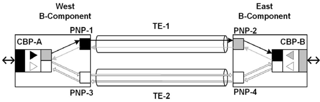
Figure 26-12—PBB-TE point-to-point protection switching
The ESPs are provided by configuring entries in the FDBs on all the Bridges that these ESPs need to pass through. On the terminating IB-BEBs, the VLAN membership of each participating port has to be configured for the B-components. In Figure 26-12, this is depicted by the color of the boxes that are placed inside each of the B-Component boxes. For example, the upper right PNP-1 port on the West B-component is a member of the VID-1 (black), while the CBP on the same component is a member of VID-2 (gray) and VID-3 (white). Only frames tagged with the appropriate VID parameter can egress these ports.
NOTE 3—The PNPs are shown for illustrative purposes only and that there is no explicit requirement to diversify PNPs on the terminating IB-BEBs.
Each of the TESIs is monitored by an independent MA. One MA is set to monitor the top (TE-1) TESI and a second to monitor the bottom (TE-2) TESI. Each of these two MAs is associated with a pair of ESPs and identified by their corresponding 3-tuples. Two Up MEPs, associated with the MA monitoring the TE-1 service instance, are configured on the CBPs that terminate the TE-1 service instance. Each of these MEPs has its own primary VID, VID-1 (black) for the MEP on the West B-component associated with the TE-1 service instance, and VID-2 (gray) for the MEP on the East B-component. In this configuration each MEP receives frames that are tagged with the ESP-VID corresponding to the primary VID of the associated remote MEP and can only send frames that are tagged with its own primary VID. In particular, in the depicted example the MEP for the top entity on the West B-component can send only CCMs tagged with VID-1 (black) and receive CCMs tagged with VID-2 (gray), while the corresponding MEP on the East component can only send CCMs tagged with VID-2 (gray) and receive CCMs tagged with VID-1 (black). The primary VID of each MEP is depicted by the color of the MEP. It should be also noted that all the depicted ports in Figure 26-12 have their Enable Ingress Filtering parameter (8.6.2) reset to its default value, i.e., Disable Ingress Filtering.
Data traffic is mapped to a TESI by configuring the CBP parameters (6.11). In particular, the CBP I-SID is used to allow specific service instances to be carried by the TESI while the entries of the B-VID column in the Backbone Service Instance table are indicating how to map the identified service instances to a specific ESP. The CBP’s B-VID value is depicted in Figure 26-12 by the color of the vertical bars (black for CBP-A, gray for CBP-B) placed at the tips of the arrows representing the set of backbone service instances.
As a result customer frames that need to be transported by a TESI and are identified by a specific I-SID and reach the CBP on the West B-component from the left can be mapped to the black ESP or the white ESP while frames on the same service that reach the CBP on the East B-component from the right will be mapped to the gray ESP or the white ESP based on the CBP’s configured B-VID value. If all the services are normally mapped to the black ESP and gray ESP, then TE-1 would correspond to the working entity and TE-2 to a stand-by protection entity. Irrespective of how the data traffic is mapped to the TESIs, CCM frames are exchanged on both TESIs in order to regularly check the provided connectivity.
If a fault occurs on any of the ESPs, the MEP on the receiving end will be notified. In particular if a fault on the black ESP occurs, as shown in Figure 26-13, the MEP on the East B-component will declare a remote MEP defect by setting the rMEPCCMdefect parameter (20.19.1). The timer counter for timing out CCMs has a granularity finer than or equal to 1/4 of the time represented by the CCMinterval variable (20.8.1). A Bridge does not set rMEPCCMdefect within (3.25 CCMinterval) seconds of the receipt of a CCM, and sets rMEPCCMdefect within (3.5 CCMinterval) seconds after the receipt of the last CCM. The setting of the rMEPCCMdefect parameter will result in a change of the appropriate B-VID entries in the Backbone Service Instance table, of the east CBP from the gray VID-2 to the white VID-3, which is the ESP-VID of the associated ESP on the protection TESI.
NOTE 4—The B-VID parameter will also change when the xConCCMdefect (20.23.3) or the errorCCMdefect (20.21.3) parameters are set as these indicate a very serious misconfiguration problem.
All subsequent CCMs sent by the east gray MEP on TE-1 will have the RDI field set for as long as proper CCMs are not received by the MEP. A reception of a CCM frame with the RDI field set (or an event that causes setting of the someRMEPCCMdefect, xConCCMdefect or errorCCMdefect) by the MEP associated with TE-1 on CBP-A will cause a change of the appropriate B-VID entries in the Backbone Service Instance table of the CBP-A on the West B-component, to the preconfigured value of the protection ESP. The result will be to move the affected service instances to the protection TE-2 service instance as depicted Figure 26-13. Consequently, the approximate maximum time before a bidirectional switch occurs following a unidirectional failure would be approximately equal to (3.5 CCMinterval) + the time required for a CCM PDU to travel between the MEPs monitoring the TESI + the time to update the associated Backbone Service Instance table entries.
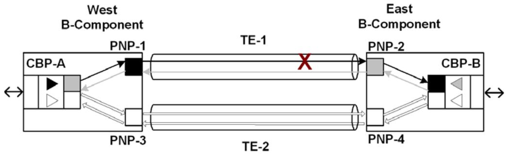
Figure 26-13—Mapping data traffic to the protection entity
26.10.3 Protection Switching state machines
The local protection commands and protection behavior specified here follow the architectural model used in ITU-T G.8031 [B42]. The relationships among the protection switching state machines are illustrated in Figure 26-14. That figure uses conventions similar to those of 13.24, and of Figure 13-13: open arrows denote variables that are set by one state machine and both read and set by another; closed arrows denote variables that are set by the owning state machine, and only read by other state machines.
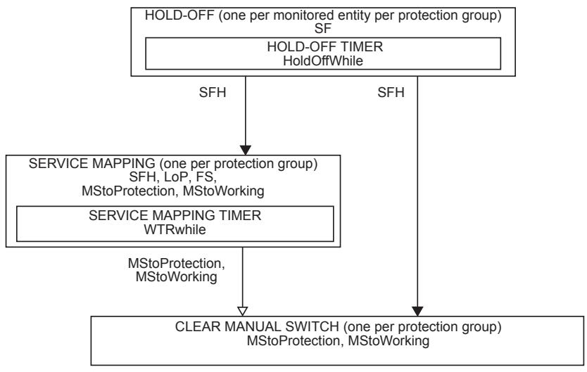
NOTATION:
A variable is shown within the machine that uses it, or between machines with an arrow head style that indicates how it is used to communicate:
Not changed by the target machine.
Set (or cleared) by the originating machine, cleared (or set) by the target machine.
Figure 26-14—Relationships of the Protection switching state machines—overview
There is one set of Protection Switching state machines per protection group on each Bridge that terminates the protection group. The protection group consists of the working and the protection entities. The Protection Switching state machine reuses the defect variables that are presented in Table 20-1. Variables and procedures that are preceded with “w.” refer to the working entity while those that are preceded with “p.” refer to the protection entity. These internal prefix/entity associations remain the same following a protection switch to the protection entity.
26.10.3.1 Notational conventions used in state diagrams
The Protection Switching state machines are specified using the notational conventions defined in Annex E.
26.10.3.2 State machine timers
The timer variables declared in this subclause are part of the specification of the operation of Protection Switching. The accompanying descriptions of their meaning and use are provided to aid in the comprehension of the protocol only, and are not part of the specification.
One instance of the following may be implemented per Service Mapping state machine:
a) WTRwhile (26.10.3.2.1)
One instance of the following may be implemented per Hold-off state machine:
b) HoldOffWhile (26.10.3.2.2)
26.10.3.2.1 WTRwhile
A timer to be used to prevent frequent operation of the protection switch due to an intermittent defect. This timer allows for a fixed period of time to elapse before data traffic is mapped from the protection entity to the working entity when in revertive mode.
26.10.3.2.2 HoldOffWhile
In order to coordinate timing of protection switches at multiple layers or across cascaded protected domains, a hold-off timer may be required. The purpose is either to allow a server layer protection switch to have a chance to fix the problem before switching at a client layer, to allow an upstream protected domain to switch before a downstream domain, or to allow the inner protected domain to switch before the outer protected domain in the case of IPS nested protection domains.
26.10.3.3 Protection Switching variables
The following variables are defined for the Protection Switching state machines:
a) BEGIN (26.10.3.3.1)
b) SF (26.10.3.3.2)
c) SFH (26.10.3.3.3)
d) LoP (26.10.3.3.4)
e) FS (26.10.3.3.5)
f) MStoProtection (26.10.3.3.6)
g) MStoWorking (26.10.3.3.7)
h) WTRTime (26.10.3.3.8)
i) HoldOffTime (26.10.3.3.9)
Table 26-8 illustrates the inherent priority of each protection request.
Table 26-8—Protection Requests Hierarchy
<table><tr><td>Priority</td><td>Request</td></tr><tr><td>highest</td><td>LoP</td></tr><tr><td></td><td>FS</td></tr><tr><td></td><td>p.SF</td></tr><tr><td></td><td>w.SF</td></tr><tr><td></td><td>MStoProtection, MStoWorking</td></tr><tr><td></td><td>WTR</td></tr><tr><td>lowest</td><td>NoRequest</td></tr></table>
NOTE—The priorities associated with the various requests in this table are in general alignment with the corresponding priorities in ITU-T G.8031 [B42]. The only difference is that the precedence of $\mathrm { p . S F }$ and FS are inverted since ITU-T G.8031 relies on an APS protocol to be running on the protection path.
26.10.3.3.1 BEGIN
This is a Boolean variable controlled by the system initialization process. A value of TRUE causes all Protection Switching state machines per protection group to continuously execute their initial state. A value of FALSE allows these state machines to perform transitions out of their initial state, in accordance with the relevant state machine definitions.
26.10.3.3.2 SF
SF is the logical OR of someRMEPCCMdefect (20.35.5), someRDIdefect (20.35.7), xConCCMdefect (20.23.3), and errorCCMdefect (20.21.3).
NOTE—Locally detected MAC/PHY faults may also be components of SF (e.g., to enable potentially faster fault detection), but are outside the scope of this standard.
26.10.3.3.3 SFH
A Boolean flag set and cleared by the Hold-off state machine to indicate that SF is set for a period which is equal to, or larger than, the HoldOffTime. The variable will be set equal to SF if the Hold-Off timer is not supported.
26.10.3.3.4 LoP
A Boolean flag indicating the administrative state of the protection entity. If set, it prohibits the use of the protection entity. Its value can only be controlled by an administrator action [item b2) in 12.18.2.3.2].
26.10.3.3.5 FS
A Boolean flag indicating the presence of an administrative command to force switch the data traffic to the protection entity. Its value is set to 1 by an administrator action [item b3) in 12.18.2.3.2 or 12.24.2.3.2]. It can be reset by an administrator action that corresponds to a request of the same or higher priority according to Table 26-8.
26.10.3.3.6 MStoProtection
A Boolean flag indicating the presence of an administrative command to manually switch the data traffic to the protection entity, in the absence of a failure of the working or the protection entity. Its value is set to 1 by an administrator action [item b4) in 12.18.2.3.2 or 12.24.2.3.2]. It can be reset by an administrator action that corresponds to a request of the same or higher priority according to Table 26-8 and by the operation of the Clear Manual Switch state machine.
26.10.3.3.7 MStoWorking
A Boolean flag indicating the presence of an administrative command to manually switch the data traffic to the working entity in the absence of a failure of the working or the protection entity. Its value is set to 1 by an administrator action [item b5) in 12.18.2.3.2 or 12.24.2.3.2]. It can be reset by an administrator action that corresponds to a request of the same or higher priority according to Table 26-8 and by the operation of the Clear Manual Switch state machine.
26.10.3.3.8 WTRTime
The wait-to-restore (WTR) period, as provided by the corresponding managed object item e) in 12.18.2.1.3 or item h) in 12.24.2.1.3]. May be configured by the operator in 1 min steps between 5 and 12 min; the default value is 5 min. A value of 0 indicates nonrevertive mode. The overall accuracy of the WTR timer (e.g., < ±25 ms) should be sufficient to allow both ports at the protection domain termination to revert to the working entity in less than 50 ms.
26.10.3.3.9 HoldOffTime
The Hold-Off period as provided by the corresponding managed object [item f) in 12.14.6.1.3 or item i) in 12.24.2.1.3]. The suggested range of the hold-off timer is 0 to 10 s in steps of 100 ms (accuracy of ±5 ms); the default value is 0.
26.10.3.4 Protection Switching procedures for PBB-TE TESI Protection
The following procedures are defined for the Service Mapping state machine:
a) mapDataToWorking() (26.10.3.4.1)
b) mapDataToProtection() (26.10.3.4.2)
NOTE 1—Since a merging selector is used, there is the potential for mis-ordered frames at egress due to differential delay between the working and protection TESIs following a protection switch. If this is a concern, then briefly discarding frames prior to executing either mapDataToX() processes described in 26.10.3.4.1 or 26.10.3.4.2 will avoid the issue (e.g., 1 ms is equivalent to a 20% differential delay across 1000 km of fiber).
NOTE 2—The procedure descriptions in this subclause are specific to PBB-TE TESI Protection. A description of the corresponding procedures for IPS can be found in 26.11.4.1.1 and 26.11.4.1.2.
26.10.3.4.1 mapDataToWorking()
Maps the customer service(s) that are to be transported by a TE protection group [item b) in 12.18.2.1.3], to the working TESI identified by the 3-tuples <remote CBP MAC, local CBP MAC, ESP-VID(w)>, <local CBP MAC, remote CBP MAC, ESP-VID(w’)>, by setting the VID values of the corresponding I-SID entry(-ies) in the Backbone Service Instance table to the ESP-VID(w).
26.10.3.4.2 mapDataToProtection()
Maps the customer service(s) that are to be transported by a TE protection group [item b) in 12.18.2.1.3], to the protection TESI identified by the 3-tuples <remote CBP MAC, local CBP MAC, ESP-VID(p)>, <local CBP MAC, remote CBP MAC, ESP-VID(p’)>, by setting the VID values of the corresponding I-SID entry(ies) in the Backbone Service Instance table to the ESP-VID(p).
26.10.3.5 Protection Switching state machine diagram
The Protection Switching state machines implement the function specified by the state diagrams in Figure 26-15, Figure 26-16, and Figure 26-17, the variables in 26.10.3.3, and the procedures in 26.10.3.4. The Hold-off state machine shall be present only when the Hold-off timer is supported.
The current state of the Service Mapping state machine is available as a managed object [item c) in 12.18.2.1.3].
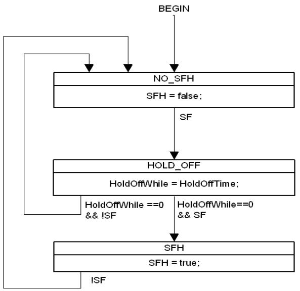
Figure 26-15—Hold-off state machine
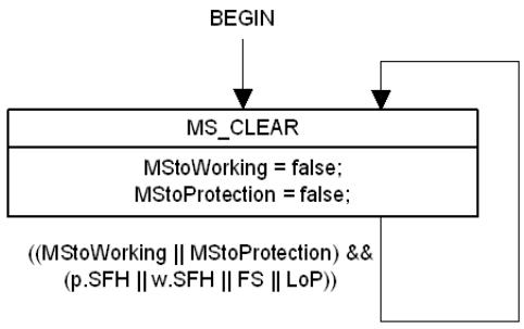
Figure 26-16—Clear Manual Switch state machine
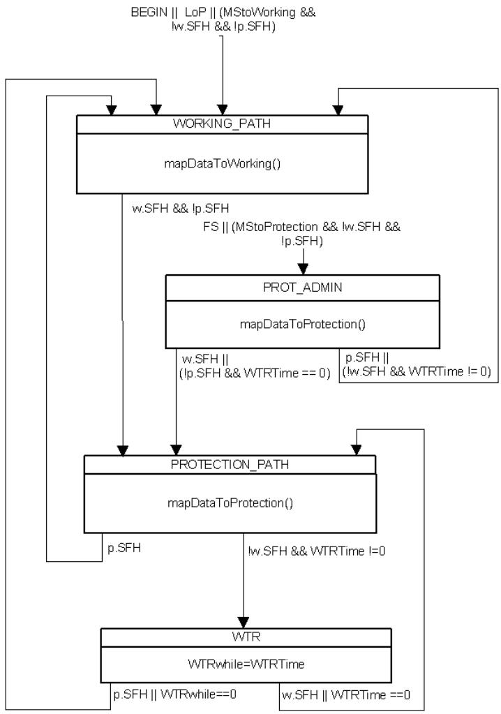
Figure 26-17—Service Mapping state machine
26.11 IPS in PBB-TE Region
In addition to supporting end-to-end linear protection for TESIs (26.10), PBB-TE supports localized protection of selected TESIs traversing a common sequence of PNPs. Such a sequence of PNPs, together with the intervening MAC relay entities and LANs, is called an Infrastructure Segment. The group of TESIs associated with the Infrastructure Segment is protected from the failure of one or more components $( \mathrm { i . e . , }$ port, LAN, or MAC Relay Entity) of the Infrastructure Segment. The method of providing such protection is called Infrastructure Protection Switching (IPS). 1:1 IPS and M:1 IPS are described by this standard. Support for IPS is optional. If IPS is supported, 1:1 IPS is required, and M:1 IPS is optional. IPS may be triggered automatically by a change in the operational state of an Infrastructure Segment or manually by administrative command.
NOTE—A complete discussion on the various protection switching mechanisms and terminology is provided by ITU-T G.8031 [B39]. The ITU-T uses the term “bridge” for the logical entity that selects either or both of the transmit paths at the sending end of a protected domain. This is not to be confused with the term “Bridge” used in this standard.
As illustrated in Figure 26-18, a Bridge supporting IPS is a PBB. Definitions of entities associated with an Infrastructure Segment and properties of such entities are as follows:
a) A PBB terminating the Infrastructure Segment is a Segment Endpoint Bridge (SEB);
b) A PBB in the interior of the Infrastructure Segment is a Segment Intermediate Bridge (SIB);
c) A PNP terminating the Infrastructure Segment is called a Segment Endpoint Port (SEP);
d) A PNP in the interior of the Infrastructure Segment is called a Segment Intermediate Port (SIP);
e) A SEB contains one SEP and does not contain a SIP;
f) A SIB contains exactly two SIPs and, by definition, cannot contain a SEP;
g) A SEP is connected to a single SIP or SEP in a neighboring PBB via a LAN;
h) A SIP is connected to one other SIP within the SIB via the MAC Relay Entity and is connected to a single SEP or SIP in a neighboring PBB via a LAN.
The role of SEB or SIB is assigned to a PBB only with respect to a particular Infrastructure Segment. Similarly, the role of SEP or SIP is assigned to a Port only with respect to a particular Infrastructure Segment.
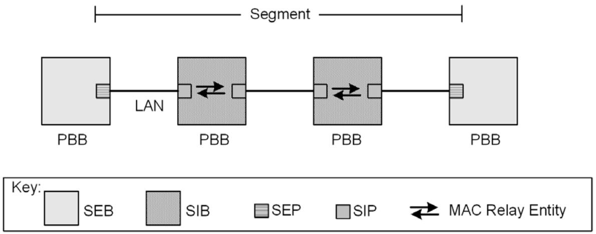
Figure 26-18—Segment terminology and properties
26.11.1 Infrastructure Segment monitoring
As illustrated in Figure 26-19, each Infrastructure Segment is associated with an MA for purposes of determining the connectivity state of that Infrastructure Segment. The Infrastructure Segment MA is associated with a pair of co-routed counterdirectional Infrastructure Segment Monitoring Paths (SMPs). Each SMP is identified by an <SMP-DA, SMP-SA, SMP-VID> 3-tuple that is known as an SMP-ID. The SMP-SA takes the value of the MAC address of the SEP from which the SMP originates. The SMP-DA takes the value of the MAC address of the SEP in which the SMP terminates. It follows from the co-routed and counterdirectional properties of the pair of SMPs that the SMP-DA value of one SMP in the pair of SMPs is equal to the SMP-SA value of the other SMP of the pair. The SMP-VID is a VID associated with a special value of the Multiple Spanning Tree Instance Identifier (MSTID) in the MST Configuration Table, the TE-MSTID, indicating that the VID is under the control of an external agent (8.9). The pair of SMP-IDs associated with an Infrastructure Segment is known as an Infrastructure Segment Identifier (SEG-ID). The MA managed object (12.14.6) associated with an Infrastructure Segment specifies the SEG-ID identifying that Infrastructure Segment. The value of the SEG-ID is inherited by the MEP associated with the Infrastructure Segment MA..
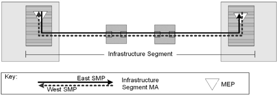
Figure 26-19—Infrastructure Segment monitoring
The operational state of the Infrastructure Segment is indicated by the Signal Fail (SF) variable (26.10.3.3.2) of the Protection Switching state machines (26.10.3). A value of TRUE indicates that the associated Infrastructure Segment is not operational. A value of FALSE indicates that the associated Infrastructure Segment is operational.
NOTE—For proper network operation, each SMP, of the pair of SMPs identifying an Infrastructure Segment MA, is represented by a Static Filtering Entry configured via the Create Filtering Entry operation (12.7.7.1) in each SIB along the path of the Infrastructure Segment. The SMP-ID <SMP-DA, SMP-SA, SMP-VID> would be represented by the Static Filtering Entry <SMP-DA, SMP-VID, outbound port value>. The outbound port value is the port number of the port by which the SMP exits the SIB. Proper operation further includes the creation, at each SEP, of a Maintenance Domain managed object (12.14.5), a Maintenance Association managed object (12.14.6), and a Maintenance association Endpoint managed object (12.14.7) associated with the Infrastructure Segment MA.
26.11.2 1:1 IPS
Figure 26-20 depicts two Infrastructure Segments with a TESI that has been provisioned to fully traverse the upper Infrastructure Segment. The Infrastructure Segment traversed by the provisioned TESI is known as the Working Segment with respect to that TESI. The lower Infrastructure Segment terminates in the same pair of SEBs that terminates the Working Segment but is otherwise diverse from the Working Segment. The lower Infrastructure Segment is known as the Protection Segment with respect to the TESI that traverses the Working Segment.
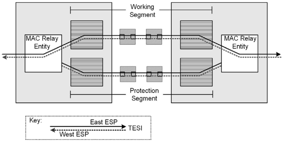
Figure 26-20—Working Segment and Protection Segment
26.11.2.1 Infrastructure Protection Group (IPG)
The associated Working and Protection Segments depicted in Figure 26-20 are said to form an IPG. The Working and Protection Segments are fully disjoint except for the common SEBs in which they terminate; that is, they share no common SEP, SIB, SIP, LAN, or MAC Relay Entity. One or more TESIs, each identified by a TE-SID are associated with an IPG at the SEB by which the TESI enters that IPG. A TESI is associated with the IPG via the Write IPG managed object (12.24.2.2). Multiple TESIs may be associated with an IPG. TESIs associated with an IPG may have diverse end-to-end paths, but they follow a common path traversing the IPG. Two or more TESIs may be associated with ESPs having the same <ESP-DA, ESP-VID> 2-tuple. In particular this can occur if the TESIs are distinguished only by different values of ESP-SA. In such cases where TESIs share a common value of <ESP-DA, ESP-VID>, the association of one such TESI with an IPG at a SEB implies that all such TESIs are associated with that IPG. In other words, all such TESIs are protected by the IPG, or no such TESIs are protected by the IPG.
NOTE—An Infrastructure Segment can be associated with more than one IPG. For example, the operator can designate Infrastructure Segment 1 as the Working Segment of IPG1 and Infrastructure Segment 2 as the Protection Segment of IPG1. The operator can concurrently designate Infrastructure Segment 2 as the Working Segment of IPG2 and Infrastructure Segment 1 as an Protection Segment of IPG2. This property can be utilized as a method of load sharing across multiple Infrastructure Segments during normal operation.
26.11.2.1.1 Nested IPGs
IPGs are said to be nested with respect to a TESI if
a) The TESI is associated with both IPGs and
b) The set of SEPs and SIPs comprising the Working Segment of one IPG, the inner IPG, is identical to a contiguous sequence of SIPs contained within the Working Segment of the other IPG, the outer IPG.
In Figure 26-21, IPG2 (dashed) is nested within IPG1 (solid). IPG1 is the outer IPG, and IPG2 is the inner IPG. The Working Segment of the inner IPG is fully contained within the Working Segment of the outer IPG. The SEBs associated with the outer IPG are different from those associated with the inner IPG. Each nested IPG deploys an independent set of MAs for the purpose of monitoring the operational state of Infrastructure Segments associated with that IPG.
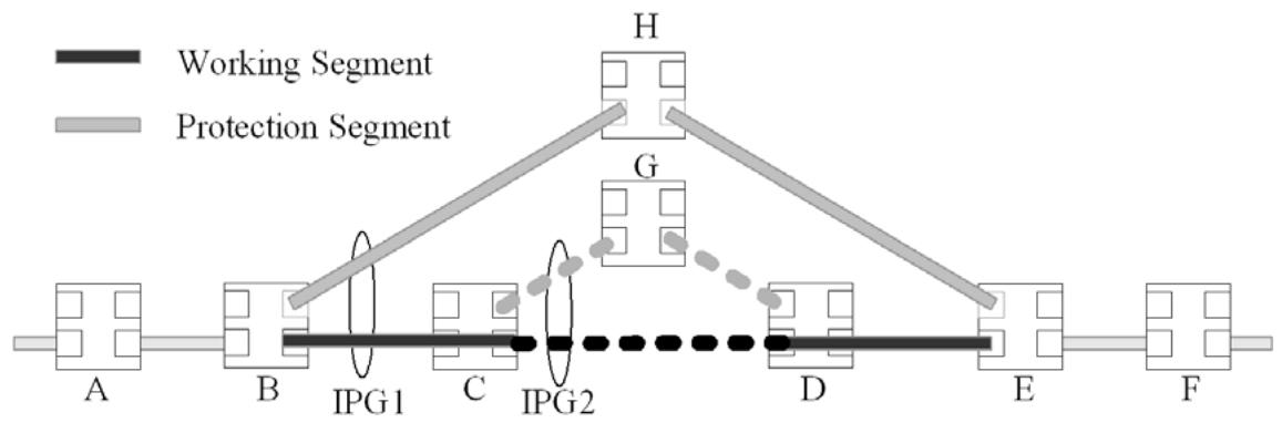
Figure 26-21—Nested IPGs
NOTE—Two IPGs are said to overlap with respect to a TESI if (a) the TESI is associated with both IPGs and (b) the IPGs share a sequence of PNPs. Designing networks having IPGs that overlap, but are not nested, requires careful study of issues not specifically identified in this standard.
26.11.2.2 Protection Switching method
When a TESI is assigned to an IPG by provisioning, traffic associated with that TESI transits the IPG via the Working Segment or the Protection Segment as directed by the Protection Switching state machines (26.10.3). In the absence of faults or outstanding administrative commands, TESI traffic transits the IPG via the Working Segment. The Protection Switching state machines can cause the TESI traffic to transit the IPG via the Protection Segment by invoking the Protection Switching procedure mapDataToProtection() $( 2 6 . 1 1 . 4 . 1 . 2 )$ . This procedure causes the value of the outbound Port field of the FDB entry corresponding to the ${ < } \mathrm { E S P _ { i n } { - } D A }$ , $\mathrm { E S P _ { i n } \mathrm { - V I D \mathrm { > } } }$ 2-tuple of each TESI associated with the IPG to be assigned the Port Number associated with the Protection Segment. The notation “ESPin” denotes the ESP, of the pair of ESPs associated with the TESI, that enters the IPG via the SEB. The Protection Switching state machines can cause the traffic to transit the IPG via the Working Segment by invoking the Protection Switching procedure mapDataToWorking() (26.11.4.1.1). This procedure causes the value of the outbound Port field of the FDB entry corresponding to each $\mathrm { \overline { { < E S P } } _ { i n } \mathrm { \overline { { - D A } } , \ E S P _ { i n } \mathrm { - V I D } } } / \mathrm { D } { > } \ 2$ -tuple of each TESI associated with the IPG to be assigned the Port Number associated with Working Segment. The two SEBs associated with the IPG perform protection activities independently. At any point in time, traffic associated with an IPG is carried on either the Working Segment or the Protection Segment. The Infrastructure Segment carrying the TESI traffic is known as the active Infrastructure Segment.
NOTE—Proper operation of the network requires that the FDB entry provisioned in a SIB to forward traffic along an Infrastructure Segment associated with the IPG identify only a single outbound Port. In other words, the portion of a TESI transiting an IPG is provisioned as point-to-point, without regard to whether the TESI is point-to-point or point-tomultipoint from an end-to-end perspective.
26.11.2.3 Hold-off timer
An IPG is provisioned with a “hold-off timer” value. The hold-off timer delays protection action associated with the failure of an Infrastructure Segment. The delay provides a lower layer with the opportunity to take corrective action before IPS is performed. Use of the hold-off timer can increase the total time required to recover from a failure.
In the case of nested IPGs, proper operation of the network requires that the outer IPG be provisioned with a “hold-off timer” value greater than that of the inner IPG. The outer IPG Working Segment is provisioned to coincide with the path of the inner IPG Working Segment. CCM traffic monitoring the outer IPG Working Segment traverses the Active Segment of the Inner IPG. The TESI list associated with the Inner IPG Endpoint Bridge is provisioned to include the SEG-ID associated with the CCM on the outer IPG Working Segment MA that ingresses the Inner IPG SEB. Thus, on a failure of the inner IPG Working Segment, traffic associated with the outer IPG Working Segment, including the CCM traffic associated with the outer IPG Working Segment MA, is protected. The outer IPG will not be aware of the protection switch of the inner IPG and will not perform protection switching activities.
26.11.2.4 Reversion
An IPG is provisioned to operate in revertive mode or nonrevertive mode. In revertive mode, traffic is switched from the Protection Segment to the Working Segment when the Working Segment becomes operational. In nonrevertive mode, traffic remains associated with the Protection Segment when the Working Segment becomes operational unless
a) The Protection Segment fails or
b) Traffic is switched to the Working Segment by administrative command.
An IPG operates in revertive mode if that IPG is provisioned to support M:1 IPS.
26.11.2.4.1 Wait-to-restore timer
An IPG operating in revertive mode is provisioned with a “wait-to-restore (WTR) timer” value. The WTR timer delays reversion from the Protection Segment to the Working Segment on recovery of the Working Segment. Use of the WTR timer reduces the severity of “flapping,” or rapid oscillation, that may occur if the Working Segment is experiencing intermittent connectivity failure. Setting the WTR time to zero indicates that the IPG is operating in nonrevertive mode.
26.11.2.5 Administrative commands
IPS supports the following administrative commands:
Lockout of Protection (LoP): allows the operator to suppress automatic switching from Working Segment to Protection Segment;
Forced Switch (FS): allows the operator to force traffic to the Protection Segment as if a connectivity failure exists on the Working Segment. The behavior persists until the command is withdrawn;
Manual Switch to Protection (MStoProtection): switches traffic to the Protection Segment, but does not force traffic to remain associated with the Protection Segment;
Manual Switch to Working (MStoWorking): switches traffic to the Working Segment, but does not force traffic to remain associated with the Working Segment.
26.11.3 IPS Control entity
The IPS Control entity contains the 1:1 IPS state machines (26.11.4) and, if M:1 IPS (26.11.5) is supported, the M:1 IPS state machines (26.11.5.1). There is an instance of the IPS Control entity for each SEB.
As shown in Figure 26-22, the operation of the IPS state machines depends upon input from Bridge Management and from each Infrastructure Segment MA associated with the IPG. The input from Bridge Management includes the list of TESIs [12.14.2.1.2 e)] associated with the IPG and Administrative commands (26.11.2.5) associated with the IPG. The outbound Port field of a Static Filtering Entry associated with an IPG can be modified by IPS Control. When a Static Filtering Entry is no longer associated with an IPG, the Outbound Port value of that Static Filtering Entry is restored by IPS control to the Port associated with the Working Segment of the IPG and IPS Control cannot subsequently modify the Outbound Port value. While the Outbound Port value can be modified by IPS Control, addition and deletion of FDB entries remains under the control of Bridge Management.
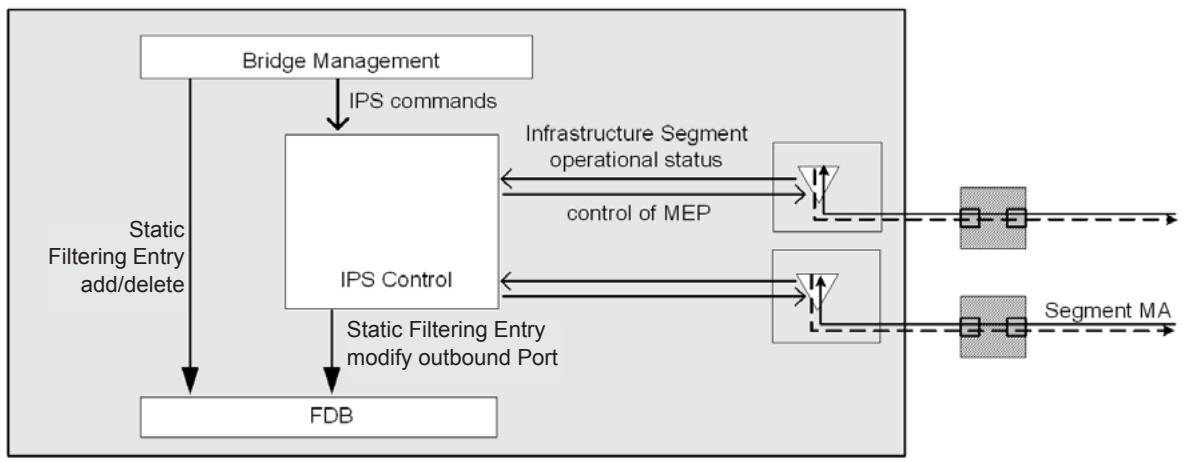
Figure 26-22—IPS Control entity
IPS Control maintains the following entities associated with the IPG:
a) The SEG-ID identifying the Working Segment MA;
b) The SEG-ID identifying the Protection Segment MA;
c) The 1:1 IPS state machines;
d) The list of the TESIs describing traffic protected by the IPG;
When an IPG is associated with optional M:1 IPS, the following additional entities are maintained:
e) The list of SEG-IDs identifying the MAs of candidate Protection Segments;
f) The M:1 IPS state machines.
26.11.4 1:1 IPS state machines
Protection switching for point-to-point TESIs (26.10) and 1:1 IPS (26.11.2) both utilize Protection Switching state machines (26.10.3). In the case of 1:1 IPS, the “Protection Group” is an “IPG,” the “working entity” is the “Working Segment,” and the “protection entity” is the “Protection Segment.” One set of Protection Switching state machines is instantiated per IPG per SEB.
26.11.4.1 Procedures referenced by the 1:1 IPS state machines
The procedures mapDataToWorking() and mapDataToProtection() referenced by the 1:1 IPS state machines and described in the subclauses that follow, differ from the procedures of the same name (26.10.3.4) referenced by the TESI Protection state machines.
26.11.4.1.1 mapDataToWorking()
This procedure changes the value of the outbound Port field of each Static Filtering Entry identified by the $< \mathrm { E S P } _ { \mathrm { i n } } \mathrm { - D A } , \mathrm { E S P } _ { \mathrm { i n } } \mathrm { - V I D } > 2$ -tuple associated with each TESI on the list of TESIs associated with an IPG to the port Number associated with the Working Segment of the IPG.
26.11.4.1.2 mapDataToProtection()
This procedure changes the value of the outbound Port field of each Static Filtering Entry identified by the $< \mathrm { E S P _ { i n } ^ { - } D A } , \mathrm { E S P _ { i n } ^ { - } V I D } > 2$ -tuple associated with each TESI on the list of TESIs associated with an IPG to the port Number associated with the Protection Segment of the IPG.
26.11.5 M:1 IPS
This subclause describes extensions to 1:1 IPS (26.11.2) supporting M:1 IPS when this optional feature is implemented. An IPG is constrained to operate in 1:1 revertive mode when that IPG supports M:1 IPS.
As illustrated in Figure 26-23, a list of candidate Protection Segments, ordered by priority value, is provisioned for each IPG. deploying M:1 IPS. The list contains at least one candidate Protection Segment. Candidate Protection Segments are mutually disjoint and disjoint from the Working Segment. The candidate Protection Segment having the highest (lowest numeric) priority among the operational candidate Protection Segments is the Protection Segment referenced by the 1:1 IPS state machine. This selected candidate Protection Segment is called the “current” Protection Segment. In the absence of any operational candidate Protection Segments, the current Protection Segment retains the value it had prior to the failure of the last candidate Protection Segment. In this case, the 1:1 IPS Protection Segment is declared to have failed. If the 1:1 IPS Protection Segment is not operational and a candidate Protection Segment becomes operational, that candidate Protection Segment assumes the role of 1:1 IPS Protection Segment, and the 1:1 IPS Protection Segment becomes operational. If a candidate Protection Segment of higher priority than the current Protection Segment becomes operational, then that candidate Protection Segment assumes the role of the 1:1
IPS Protection Segment following expiration of the M:1 wait-to-restore timer. If the current Protection Segment has changed and the 1:1 IPS Protection Segment is the active Infrastructure Segment, then Static Filtering Entries associated with TESIs protected by the IPG are updated with the Port number of the current Protection Segment as described in 26.11.2.2. Thus, M:1 IPS is deployed using an extension of 1:1 IPS that allows the current Protection Segment to be replaced by a candidate Protection Segment of higher priority, provided that such a candidate exists and is operational.
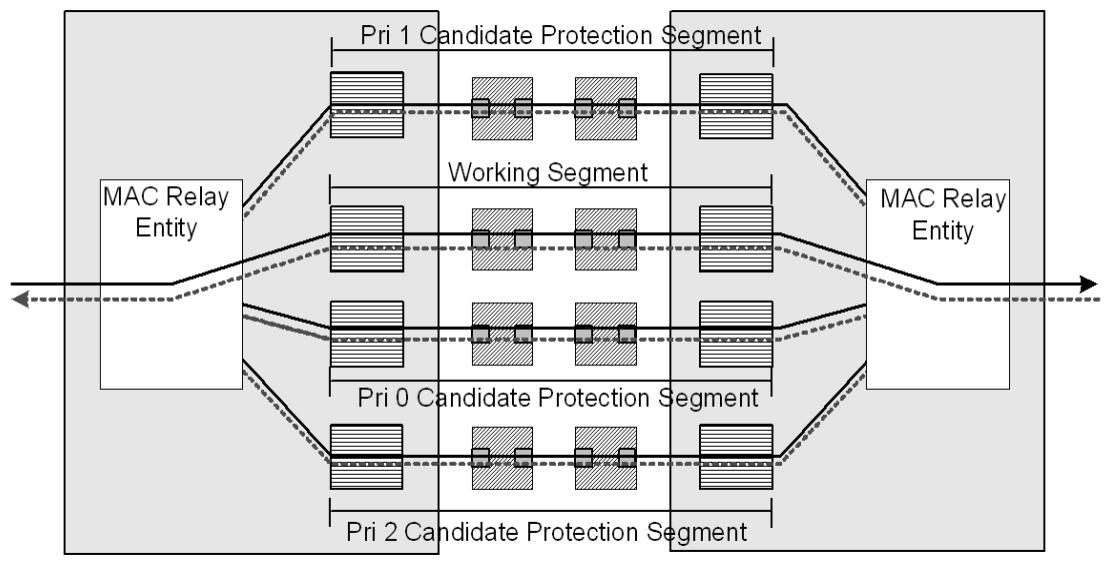
Figure 26-23—M:1 IPS
26.11.5.1 M:1 IPS state machines
There is one set of M:1 IPS state machines per IPG.
The M:1 IPS state machines comprise one M:1 Hold-off state machine (26.11.5.6) per candidate Protection Segment and one Protection Segment Selection state machine (26.11.5.7) per IPG, in addition to the 1:1 IPS state machines (26.11.4). The relationship between the M:1 IPS state machines and the 1:1 IPS state machines is illustrated in Figure 26-24.
26.11.5.2 Notational conventions used in state diagrams
The Protection Switching state machines are specified using the notational conventions defined in Annex E. Additionally, in cases of multiple instances of a state variable, each instance is represented by adding the suffix “[n]” to indicate the $\mathrm { n ^ { t h } } ^ { \mathrm { t h } }$ instance. If instances of a state variable may be associated with either the Working Segment or the Protection Segment, the references can be distinguished by prefixing “w.” or “p.” to distinguish the two cases.
26.11.5.3 State machine timers
The timer variables declared in this subclause are part of the specification of the operation of Protection Switching. The accompanying descriptions of their meaning and use are provided to aid in the comprehension of the protocol only and are not part of the specification. Timer variables deployed by the M:1 IPS state machines are
a) HoldOffWhile (26.10.3.2.2): one instance per M:1 Hold-off state machine;
b) MWTRwhile (26.11.5.3.1): one instance per M:1 Hold-off state machine.
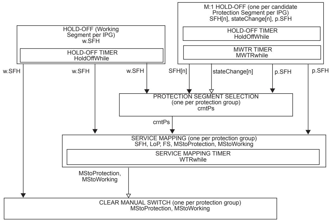
NOTATION:
A variable is shown within the machine that uses it, or between machines with an arrow head style that indicates how it is used to communicate:
Not changed by the target machine.
Set (or cleared) by the originating machine, cleared (or set) by the target machine.
Figure 26-24—M:1 IPS state machines
26.11.5.3.1 MWTRwhile
A timer to be used to prevent frequent operation of the protection switch among candidate Protection Segments due to an intermittent defect. This timer allows for a fixed period of time to elapse before data traffic is mapped from a lower priority Protection Segment to a higher priority Protection Segment when in M:1 revertive mode.
26.11.5.4 Variables referenced by M:1 IPS state machines
The following variables are referenced by the M:1 IPS state machines:
a) BEGIN (26.11.5.4.1);
b) SF (26.11.5.4.2);
c) SFH (26.11.5.4.3);
d) stateChange (26.11.5.4.4);
e) pri (26.11.5.4.5);
f) allPsSFH (26.11.5.4.8);
g) crntPs (26.11.5.4.6);
h) WTRTime (26.10.3.3.8);
i) MWTRTime (26.11.5.4.7); and
j) HoldOffTime (26.10.3.3.9).
26.11.5.4.1 BEGIN
This is a Boolean variable controlled by the system initialization process. A value of TRUE causes all M:1 IPS state machines per IPG to continuously execute their initial state. A value of FALSE allows these state machines to perform transitions out of their initial state, in accordance with the relevant state machine definitions.
26.11.5.4.2 SF
SF is the logical OR of someRMEPCCMdefect (20.35.5), someRDIdefect (20.35.7), xConCCMdefect (20.23.3), and errorCCMdefect (20.21.3). An instance of this variable, identified by the notation SF[n], is specified per candidate Protection Segment.
26.11.5.4.3 SFH
A Boolean flag set and cleared by the M:1 Hold-off state machine to indicate that SF is set for a period that is equal to, or larger than, the HoldOffTime. The variable is set equal to SF if the hold-off timer is not supported. An instance of this variable, identified by the notation SFH[n], is specified per candidate Protection Segment.
26.11.5.4.4 stateChange
A Boolean flag set by the M:1 Hold-off state machine and cleared by the Protection Segment Selection state machine indicating the value of SFH associated with a candidate Protection Segment has changed. An instance of the variable, identified by the notation stateChange[n], is specified per candidate Protection Segment.
26.11.5.4.5 pri
An integer value associated with each candidate Protection Segment and unique within the IPG indicating the selection priority of a candidate Protection Segment. Lower numeric values are associated with higher priority. An instance of the variable, identified by the notation pri[n], is specified per candidate Protection Segment.
26.11.5.4.6 crntPs
An integer value identifying the operational candidate Protection Segment having the highest (lowest numeric) selection priority. In the event that no candidate Protection Segment is available, the value is that of the last candidate Protection Segment to be available.
26.11.5.4.7 MWTRTime
The M:1 wait-to-restore (MWTR) period associated with reverting from a lower priority to a higher priority candidate Protection Segment, as provided by the corresponding managed object [item k) in 12.24.2.1.3]. May be configured by the operator in 1 min steps between 5 and 12 min; the default value is 5 min. A value of 0 indicates M:1 nonrevertive mode. The overall accuracy of the MWTR timer (e.g., <±25 ms) should be sufficient to allow both SEBs at the termination of the IPG to revert to the same value of the Protection Segment in less than 50 ms.
26.11.5.4.8 allPsSFH
The logical AND of the value of SFH[n] over the M candidate Protection Segments.
26.11.5.5 Procedures referenced by M:1 IPS state machines
The following procedures are referenced by the M:1 IPS state machines:
a) highestPriOperPs() (26.11.5.5.1);
b) setPs(n) (26.11.5.5.2); and
c) mapDataToProtection() (26.10.3.4.2).
26.11.5.5.1 highestPriOperPs()
Returns the identity of the highest priority candidate Protection Segment for which SFH[n] == FALSE or, in the event that $\mathrm { S F H } [ \mathrm { n } ] \mathrm { = = } \mathrm { T R U E }$ for all candidate Protection Segments, the value NULL.
26.11.5.5.2 setPs(n)
Establishes the $\mathrm { n } ^ { \mathrm { t h } }$ candidate Protection Segment as the Protection Segment referenced by the Service Mapping state machine.
26.11.5.6 M:1 Hold-off state machine
The M:1 Hold-off state machine is specified by the state diagram in Figure 26-25 and the variables in 26.11.5.4.
NOTE—The state NO_SFH_WTR is entered only in the case that M:1 reversion has been provisioned (i.e., MWTRTime != 0) and the candidate Protection Segment “n” is operational (i.e., !SF[n]). The state allows the machine to wait a period of time (i.e., MWTRTime) before permitting the candidate Protection Segment “n” to become available for selection as the Protection Segment, thus increasing stability. If, during this time, it is determined that no candidate Protection Segments are available for selection (i.e., allPsSFH), but candidate Protection Segment $\ " { } \mathbf { n } \ w { }$ is operational, then it is prudent not to wait MWTRTime but instead to proceed directly to the selection of candidate Protection Segment “n” as the current Protection Segment. In other words, when no candidate Protection Segment has met the criterion for availability (i.e., allPsSFH), but there is a candidate Protection Segment that is operational (i.e., !SF[n]), then it is not necessary to wait MWTRTime before proceeding with selection.
26.11.5.7 Protection Segment Selection state machine
The Protection Segment Selection state machine is specified by the state diagram in Figure 26-26 and the variables in 26.11.5.4.
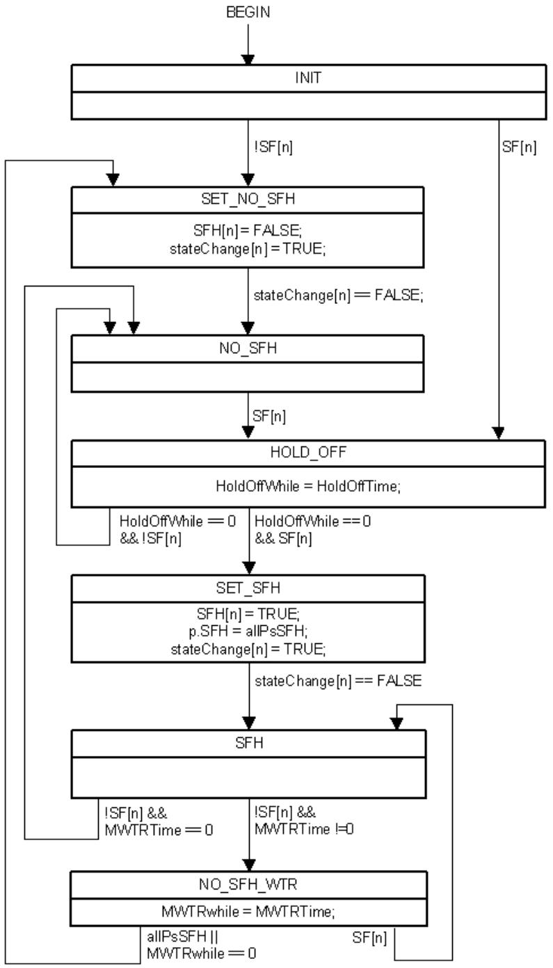
Figure 26-25—M:1 Hold-off state machine
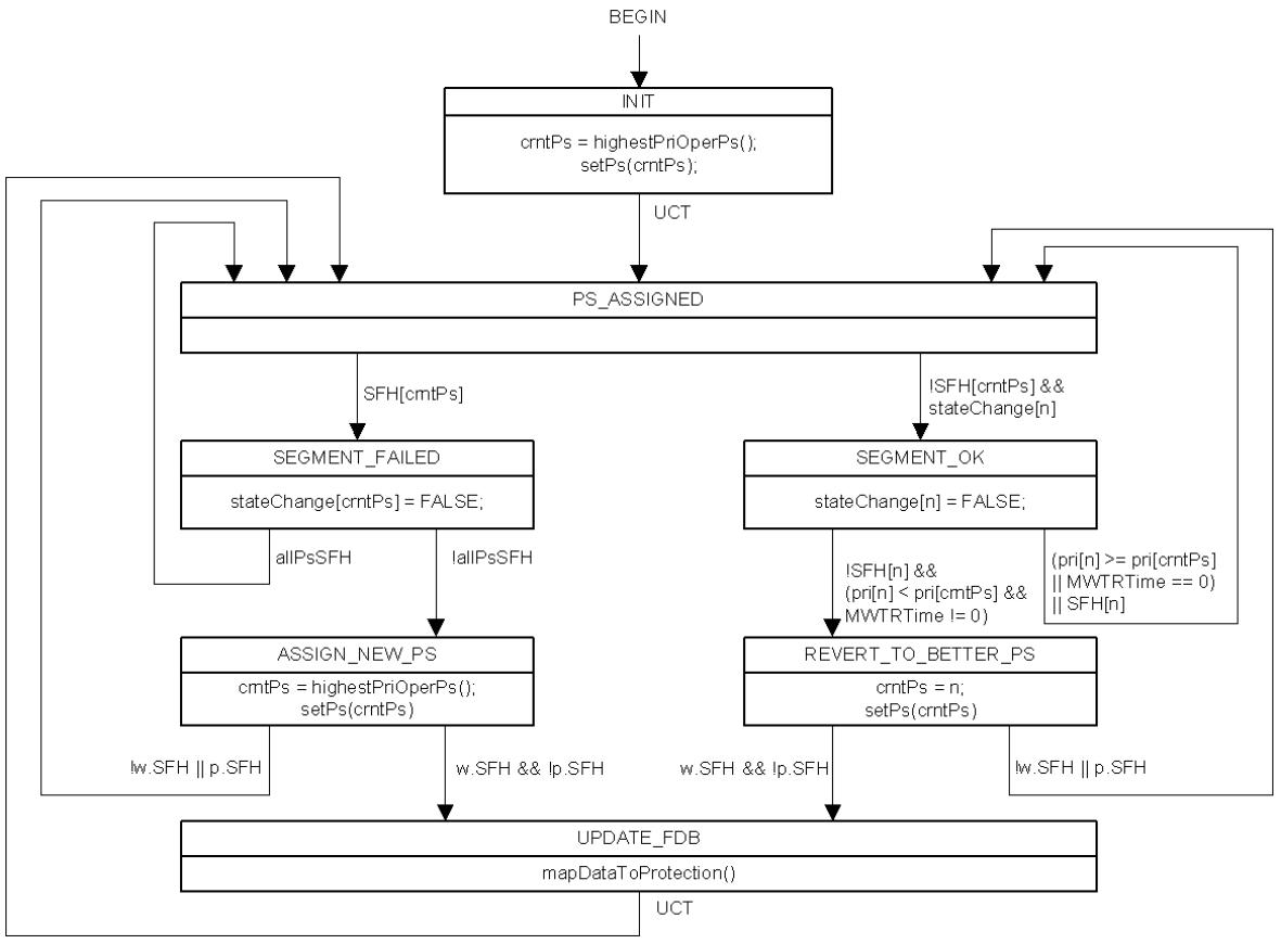
Figure 26-26—Protection Segment Selection state machine
26.12 Mismatch defect
Under equipment malfunction conditions and/or incorrect configuration, a mismatch between the mappings of the backbone service instances to the appropriate TESI at the terminating CBPs can happen. Similarly, a mismatch can occur in the mapping of a TESI to the appropriate Infrastructure Segment at the terminating PNP. To maintain the proper operation of the network, such a mismatch should be detected and reported. There can be two types of mismatch. They are as follows:
a) Protection switching incomplete
b) Working/protection configuration mismatch
An example of protection switching incomplete mismatch is when, due to equipment malfunction, the near end (East B-Component in Figure 26-13) fails to switch over but it sends a CCM with the RDI field set to the far end (West B-Component in Figure 26-13). The far end transmits to the protection TESI while the near end is still transmitting in the working TESI. Similarly a mismatch can also happen when the near end transmits to the protection TESI but the far end fails to start transmitting to the protection TESI when it receives a CCM with the RDI field set.
The mismatch can also happen because of incorrect configuration. For example, one end is configured to send traffic on working TESI while the other end is configured to send traffic on protection TESI. Or one end is configured as revertive mode while the other end is configured as nonrevertive mode. The mismatch occurs when a failure is cleared.
NOTE—Since a merging selector is used, in the case of TESI protection, there is not necessarily a traffic loss in all mismatch cases.
PBB-TE MEPs and Infrastructure Segment MEPs that support the Traffic field (21.6.1.4) can detect such a mismatch. The Mismatch state machine in 20.26 provides this capability.
26.13 Signaling VLAN registrations among I-components
A VIP is a Bridge Port. MVRP can therefore be enabled in an I-component and used to convey dynamic VLAN Registrations from I-component to I-component across a PBBN.
In the particular case of VIPs that do not emit an S-TAG, and thus use only the I-TAG to differentiate among service instances, the Multiple I-SID Registration Protocol (MIRP, Clause 39) can be enabled instead of MVRP (11.2) to signal the need to flush learned C-MAC address information from one Icomponent to another. The network administrator can select between using MVRP or MIRP to perform this signaling according to the need to minimize the number of control frames sent (MIRP) or the number of remote Icomponents affected by any given control frame (MVRP).
27 Shortest Path Bridging (SPB)
SPB provides shortest path communication for user data frames in SPT regions (Clause 3). ISIS-SPB interoperates with MSTP and RSTP (Clause 13) and STP (Clause 8 of IEEE Std 802.1D, 1998 Edition [B9]), exchanging BPDUs to determine the extent of each SPT Region and to configure full, simple, and symmetric connectivity throughout a network comprising arbitrarily interconnected Bridges and individual point-to-point LANs (13.6, 13.7). IS-IS supports point-to-point links and shared LANs; however, only pointto-point is considered for ISIS-SPB in this specification. A future revision may add shared media. The Clause 13 SPB description allows for both point-to-point links and shared media.
Within an SPT Region (7.4, 13.6), the active topology that supports the frames for any given Base VID can be chosen (27.4) by the network administrator to be one of the following:
The Internal Spanning Tree (IST), or
— A Multiple Spanning Tree Instance (MSTI), or
— A set of Traffic Engineering service instances (TESIs), or
A set of shortest path trees (SPT Set), one SPT rooted at each SPT Bridge and supporting frames transmitted into the region through that Bridge.
Multiple equal cost unicast paths and multicast trees that spread traffic rooted at each SPT Bridge over multiple SPTs. This ECMP connectivity is only supported by SPT Bridges using SPBM mode.
Clause 28 specifies the use of ISIS-SPB to calculate the IST and multiple SPT Sets (supporting different ECTs) within an SPT Region. Clause 13 specifies the use of MSTP to calculate MSTIs, and state machines that use the results provided by ISIS-SPB for each SPT to prevent loops within and between regions while maintaining or recovering connectivity as the network reconfigures (13.12, 13.14–13.40, 27.5). The umbrella term ISIS-SPB refers to the coordinated use of the protocols and algorithms specified in Clause 28 and Clause 13 to support SPB.
To allow SPB to support plug-and-play operation for some VLANs, while providing the administrative controls and scalability required for large scale operations, this standard specifies two complementary modes of SPT Bridges (SPBV and SPBM) for assigning each shortest path bridged frame to the correct SPT. All the Bridges in a given SPT Region agree on the method to be used to support any given VLAN. Subclause 27.19 describes network scenarios that use one or both of these methods.
If a VLAN is supported by an SPT Bridge using SPBV mode, Shortest Path VIDs (SPVIDs) are automatically allocated by ISIS-SPB and used in VLAN tags within an SPT Region. Each SPVID identifies both the VLAN and the SPT supporting transmission of a tagged frame, and Dynamic VLAN Registration Entries are created to provide connectivity while preventing loops (13.38.2). The SPVIDs for a given VLAN use a single FID that is associated with the Base VID for that VLAN (Shared VLAN Learning (SVL), 7.5, 8.8.8). VID translation (6.9) at the region boundary (7.4, 13.5, 13.12) maps SPVIDs to and from the associated Base VID.
If a VLAN is supported by an SPT Bridge in SPBM mode without ECMP, the Base VID is used in each frame’s VLAN tag within the SPT Region and identifies the VLAN and the SPT Set. Each Bridge mitigates and prevents loops (6.5.4, 13.38.2) by using the source and destination MAC address of each frame with Dynamic Filtering Entries for the Base VID, MAC address tuples. The source MAC address identifies the particular SPT from the SPT Set, and supports active topology enforcement (13.38.2, 8.6.1). When forwarding unicast frames it is not necessary to consider the particular SPT since all the SPTs in a given set transiting a given Bridge en route to a destination take the same path from that given Bridge to the destination (in other words, they are all reverse path congruent with the SPT rooted at that destination). Therefore, for unicast frames the destination MAC address is used for egress filtering as normal. SPT Bridging using SPBM mode requires the use of SPT-specific destination group MAC addresses, so loop-free multicast forwarding is also supported without requiring the source MAC address or source Bridge Port to be part of the FDB query. ISIS-SPB automatically allocates SPSourceIDs (27.10) that are used as part of each group address. Since an SPT Bridge using SPBM mode inspects source MAC addresses as a loop mitigation mechanism, those addresses have to be known before forwarding can take place and are advertised using ISIS-SPB. Learning of B-MAC addresses is not enabled when SPBM mode is used, and frames destined for unknown addresses are discarded and not flooded. The individual MAC addresses used are those of the SPT Bridges themselves, or are associated with functions provided by Provider Bridges or BEB functions that include an SPT Bridge component. SPBM group multicast addresses are local to the SPT Bridge domain [using the Locally administered (U/L) address MAC address flag (IEEE Std 802-2001)], so the use of SPT-specific group MAC addresses does not intrude on the well known global multicast space.
With ECMP (Clause 44), ISIS-SPB can configure multiple potential forwarding Ports for each individual MAC address, and forwarding port selection is performed dynamically. Forwarding Port selection is controlled by a deterministic hash function whose inputs are the SPB System Identifier and the Flow Hash carried in an F-TAG. This tends to spread traffic flows over the set of equal cost paths between the source Bridge and destination Bridge in the SPT Region while preserving frame ordering of individual flows. As a substitute for the loop prevention and mitigation techniques mentioned above, an alternative loop quenching mechanism for ECMP is realized with a TTL field included in the F-TAG. With ECMP, bidirectional and unicast-multicast congruence is no longer guaranteed (since there is no longer a single path in use between a source and destination). This enables each Backbone Service Instance group address to be independently routed and multicast traffic to be spread over a set of equal cost SPTs.
ISIS-SPB uses the same mechanism to allocate SPVIDs (for SPBV) and SPSourceIDs (for SPBM) (27.10). The MST Configuration Identifier (MCID) (8.9, 13.8) is used to ensure that all the Bridges in an SPT Region agree on the method used to support each shortest path VLAN and on the pool of SPVIDs, as well as on the other uses of VIDs (27.4). An SPSourceID is allocated to each Bridge in an SPT Region, independently of SPBM mode VLANs, while an SPVID for a given SPBV VLAN is only allocated to the SPT rooted at a given Bridge if VLAN Registration Entries and controls allow that Bridge to transmit frames assigned to that VLAN into the region (8.8, 13.6).
An SPT Bridge using SPBV mode is typically used to support a C-VLAN or S-VLAN for a single customer. An SPT Bridge using SPBM mode is typically used to support B-VLANs in PBBNs (Clause 25). Each B-VLAN can support many backbone service instances, each requiring connectivity between a subset of the BEBs participating in the B-VLAN, and each identified by an I-SID that is not processed by BCBs. An SPT Bridge using SPBM mode does not use source address learning, so unicast B-MAC frames conveying customer data are never flooded throughout the B-VLAN. Multicast frames and flooding of unknown unicast frames for a given backbone service instance are confined to paths that reach the BEBs supporting that service instance by including the I-SID in the SPT-specific destination group MAC addresses (Figure 27-3). The destination address filtering in each BCB prunes transmission of the encapsulated customer multicast frames as well as preventing loops.
MVRP (11.2) is not used within SPT Regions, as ISIS-SPB communicates VLAN registration information for VLANs supported by SPB from the SPT Bridges that provide ingress to and egress from the region to the other Bridges, thus allowing SPT Bridges using SPBV and SPBM to configure Dynamic VLAN Registration Entries for Bridge Ports within the region to provide correct VLAN connectivity when SPTs are recalculated—instead of waiting for registration information to propagate on those SPTs. SPT Bridges can use the registration information communicated within the SPT Region to participate in MVRP with Bridges outside the region (27.13) by supporting MVRP interfaces on the Region boundaries.
This clause specifies the following:
a) Protocol design and support requirements (27.1, 27.2) and design goals (27.3).
This clause further specifies how
b) Each Bridge’s configuration mechanisms specify the supporting method (SPBV, SPBM, MSTI, CIST, or PBB-TE) and SPT Set (for SPBV and SPBM) for each VLAN (27.4).
c) The boundaries of each SPT Region and ISIS-SPB adjacencies are determined dynamically by ISIS-SPB (Clause 28).
d) The information exchanged by ISIS-SPB is used (27.5), including CIST calculation (27.6, 27.7), SPT calculations (27.8), allocating SPVIDs and SPSourceIDs (27.10), and controlling the connectivity supporting each VLAN (27.13) and backbone service instance (27.15, 27.16).
e) The results of ISIS-SPB’s CIST and SPT calculations are used by the Clause 13 state machines to determine when to discard frames to ensure the calculated trees are loop-free (27.9).
f) SPVIDs are allocated to FIDs (27.11) and translated to and from Base VIDs at the boundary of an SPT Region (6.9, 13.6).
g) VLAN Registration Entries are used to forward or discard frames for each VLAN (27.13).
h) FDB entries for individual addresses are used to prevent or mitigate loops for VLANs supported by SPBM (27.14).
i) SPBM Group Addresses are assigned, and FDB entries for those addresses used to forward or discard frames for each backbone service instance for B-VLANs supported by SPBM (27.15, 27.16).
j) The SPT calculations choose between Equal Cost Trees (ECTs), making different choices for different SPT Sets, each associated with a different VLAN, enabling load spreading (27.17, 28.9.2).
This clause also
k) Provides examples of when and how SPT Bridges using SPBV and SPBM modes can be used (27.19).
27.1 Protocol design requirements
ISIS-SPB configures entries in each SPT Bridge’s FDB (8.8) to meet the following requirements:
a) The active topology will fully connect all physically connected LANs and Bridges, and stabilize (with high probability) within a short, known bounded interval after any change in the physical topology, maximising service availability (8.4).
b) Except in the case of ECMP, the active topology for any given frame remains simply connected at all times (6.5.3, 6.5.4).
c) The same symmetric active topology is used, in a stable network, for all frames for the same VLAN, i.e., between any two individual LANs those frames are forwarded through the same Bridge Ports.
d) The active topology supporting a given VLAN within an SPT Region can be chosen by the network administrator to be shortest path, the IST, or an MSTI.
e) Each active topology is predictable and reproducible, and may be influenced by management, thus allowing the application of Configuration Management following traffic analysis, to meet the goals of Performance Management (6.5 and 6.5.10).
f) The configured network can support VLAN-unaware end stations, such that they are unaware of their attachment to a single LAN or a bridged network, or their use of a VLAN (6.3).
g) The SPB mode, SPBV or SPBM, can be chosen by the network administrator independently for each VLAN using shortest paths.
SPBV mode meets the following requirements:
h) No additional constraint is placed on the values of the Individual or group MAC addresses used, and those addresses do not have to be known before being used in data frames.
i) SPVIDs are allocated to every SPT Bridge that is a potential source of frames on VLANs supported by SPBV.
j) FDB entries for a given SPVID will only be populated if they are on the shortest path to a participating boundary node.
SPBM mode meets the following requirements:
k) Multicast flooding for each backbone service instance supported by a PBBN is restricted to paths necessary to reach BEBs supporting that service instance.
l) ECMP operation enables multiple equal cost paths in the SPT Region to carry a share of unicast and multicast traffic.
NOTE—The ECMP ECT Algorithm supports multicast load spreading over up to 16 source trees per node and up to 16 shared trees.
Additionally, SPB algorithms and protocols meet the following goals, which limit the complexity of Bridges and their configuration:
m) The memory requirements associated with each Bridge Port are either a constant or a linear function of the number of Bridges and LANs in the network.
n) The communications bandwidth consumed by ISIS-SPB on any particular LAN is always a small fraction of the total available bandwidth (6.5.10).
o) Bridges do not have to be individually configured before being added to a network, other than having their MAC addresses assigned through normal procedures.
27.2 Protocol support
ISIS-SPB is configured to use one of the Group addresses from Table 8-13 to establish adjacencies and exchange PDUs. SPB running on C-VLAN components use the Customer Bridge address. SPB running on S-VLAN components use the Provider Bridge address. SPB running on B-VLAN components may use the Provider Bridge Address or one of the existing IS-IS addresses.
The use of the ISIS-SPB adjacency between Bridges is contingent on the Bridges inclusion within the same SPT Region, and thus requires they have an MCID and Auxiliary MCID (13.8, 28.12.2) where at least one matches on every adjacency in the Region (8.9.4, 13.8). MCID and Auxiliary MCID enable migration of the MCID definition allowing these Bridges to operate as one SPT Region under certain small changes. The operational set of Base VLANs and SPVIDs must be consistent during migration. This standard specifies default configurations resulting in a MCID that enables plug-and-play support of both the CIST and SPB using SPT Bridges using SPBV mode. No default recommendations are made for SPT Bridges using SPBM mode, since it is only expected to be used in managed environments.
This standard recommends defaults for Bridge and Bridge Port priorities and path costs to support the calculation of active topologies without further configuration. To allow management of those active topologies, a means of assigning values to the following are required:
a) The relative priority of each Bridge in the network (13.26.3).
b) The relative priority of each Port of a Bridge (13.27.47).
c) A Port Path Cost for each Port (13.27.25, 13.27.33).
Management of SPT topologies and of the use of SPBV or SPBM mode to support particular VLANs, also requires the following:
d) Management of the SPB objects (12.25).
e) Administrative agreement on the MCID Configuration Name and Revision Level (Clause 28).
27.3 Protocol design goals
It is highly desirable that the operation of ISIS-SPB allows the following:
a) Addition of Bridges to an existing SPT Region without disrupting existing communication.
b) SPB support for additional VLANs without disrupting existing communication.
c) Enabling or disabling SPB support for individual VLANs with minimum frame loss.
27.4 ISIS-SPB VLAN configuration
The configuration mechanisms used by MST Bridges to allocate each VLAN to a specified MSTI or the IST within an MST Region and used to allocate VIDs for PBB-TE (25.10) can be summarized as follows:
a) The VID to FID allocation table (8.8.8, 12.12.2) is used to allocate each VID to a FID.
b) The FID to MSTID Allocation Table is used to associate an MSTID with a FID (8.9.3, 12.12.2):
1) The IST is identified by the reserved MSTID value 0.
2) The use of PBB-TE is identified by the reserved MSTID value TE-MSTID (0xFFE)
3) Each MSTID in the MSTI List identifies an MSTI.
The reserved MSTID values 0 and TE-MSTID, SPBV-MSTID, SPBM-MSTID and 0xFFF are never used in the MSTI List.
SPT Bridges extend these configuration mechanisms as follows:
c) The VID to FID allocation table is used to allocate Base VIDs to FIDs, and to allocate VIDs for use as SPVIDs. SPVIDs are allocated to the reserved FID value 0xFFF. SPVIDs in use are reported by management as allocated to a FID supported by the implementation (27.11).
d) The reserved FID value 0xFFF is allocated to the reserved MSTID value 0xFFF.
e) The following MSTID values identify the SPT Bridge mode used by SPB:
1) 0xFFC—SPBM.
2) 0xFFD—SPBV.
This standard recommends default VID to FID and FID to MSTID allocations (27.2, 8.9.3) for SPT Bridges that enable plug-and-play support of both the CIST and SPB using SPBV mode.
Table 27-1 shows the VID to FID and the FID to MSTID allocation tables in a single table for the configuration example shown in Figure 27-1 for an SPT Region.
Base VID 1 is allocated to the IST and VIDs from 0x100 to 0x1FF form the SPVID Pool. Base VIDs 0x002, 0x003 and 0x004 are configured to operate in SPBM mode. Base VIDs 0x005, 0x006 and 0x007 operate in SPBV mode in the example.
Table 27-1—Allocation of VIDs to FIDs and FIDs to MSTIDs in an SPT Region (example)
<table><tr><td>VID</td><td>FID</td><td>MSTID</td></tr><tr><td>0x001</td><td>0x001</td><td>0x000</td></tr><tr><td>0x002</td><td>0x002</td><td>0xFFC</td></tr><tr><td>0x003</td><td rowspan="2">0x003</td><td rowspan="2">0xFFC</td></tr><tr><td>0x004</td></tr><tr><td>0x005</td><td>0x005</td><td>0xFFD</td></tr><tr><td>0x006</td><td rowspan="2">0x006</td><td rowspan="2">0xFFD</td></tr><tr><td>0x007</td></tr><tr><td>0x100-0x1FF</td><td>0xFFFF</td><td>0xFFFF</td></tr></table>
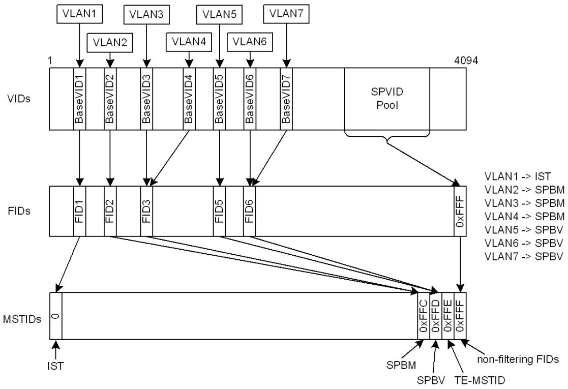
Figure 27-1—Configuring VLAN support in an SPT Region (example)
27.4.1 SPT Region and ISIS-SPB adjacency determination
It is essential that all Bridges within an SPT Region agree on the allocation of VIDs to spanning trees prior to transmission and reception of frames tagged with those VIDs. This configuration requirement is common to both SPB (13.6) and MSTP operation (13.5), and MSTP can coexist with ISIS-SPB within an SPT Region, supporting different VLANs with different VIDs. ISIS-SPB uses and extends MSTP’s configuration mechanisms and use of the MCID (8.9, 13.5, 13.8). Note the MCID (13.8) includes a digest derived from the mapping of VIDs to MSTIDs. To allow dynamic manipulation of SPVIDs without impacting the MCIDs, the mapping of SPVIDs to the FID associated with the supported Base VID is not captured in this table.
SPB configuration is highly automated. An SPT Region is created by configuring at least two adjacent Bridges with compatible information. The region grows dynamically as more SPT Bridges with the same region configuration are introduced. Once a region has been created, other VLANs can also be created. ISIS-SPB will populate forwarding only between Bridges that support the same services. The SPT region is an interconnected set of Bridges supporting the Region configuration [MCID (13.8), ISIS-SPB Configuration (27.4)] but the forwarding for any one VLAN is simply the Bridges configured to support services on that VLAN or the Bridges that lie on the shortest path between those Bridges.
The same is true of SPT Bridges operating in SPBM mode which can be added to support new VLANs on a Bridge by Bridge basis. One common operation for SPT Bridges operating in SPBM mode is to create a new ECT for a new VLAN. To support a graceful migration of services to a new Base VID, SPB allows the configuration of the Base VID before configuring services on those Base VIDs. The new Base VIDs in SPT Bridges need to be configured on all Bridges where the services reside. The U-bit (28.12.5) and Use-flag (28.12.4) are used to identify configured Base VIDs that do not have active services associated with them.
In the cases where the allocation of Base VIDs is insufficient a graceful way to support an increase in the number of Base VIDs is supported by a second (auxiliary) MCID (13.26.8, 28.12.2). Two such Bridges consider themselves to be in the same MST Region provided that at least one of their MCIDs matches with one of their SPB neighbor’s MCIDs. Non critical changes in the MCID, can be made while maintaining forwarding on the previous configuration. This is done by configuring a Bridge with a revised VID allocation that is compatible with the current allocation in use for SPB forwarding. The Bridge advertises this new MCID and continues to advertise the previous MCID as the Auxiliary MCID, maintaining its adjacencies.
When an adjacent Bridge is similarly configured, it also advertises the new MCID as its MCID to its adjacencies. The Auxiliary MCID is always the outgoing MCID. Bridges that have not been updated will continue to match their updated neighbors’ Auxiliary MCID until they have been updated, whereupon their MCID values will match again. When a Bridge sees that all its adjacencies are advertising the value of its own new MCID as their MCID, then the Bridge shall start advertising the value of its new MCID as its Auxiliary MCID also. When all Bridges have been verified to have installed the new configuration, the transfer of services to use the new VLAN allocations may be administratively initiated.
NOTE 1—The MCID verifies that each Bridge in the region agrees how each and every Base VID is to be assigned to the IST, to an MSTI, for use by PBB-TE, for support by SPBV mode, for use as an SPVID, or for support by SPBM mode. The MCID does not specify the SPT Set for VLANs supported by SPB, or preallocate SPVIDs to SPT Sets as disagreement on the former or temporary differences in the latter will not cause permanent loss of connectivity, loops, or protracted flooding. ISIS-SPB verifies that SPT Bridges agree on the SPT Set to be used to support any given SPB supported VLAN, and the Agreement Digest ensures that new connectivity is not created until that agreement has been reached.
NOTE 2—The MCID and the Agreement Digest (13.8, 28.4) can both influence the connectivity provided, and their respective roles need to be clear. MCID differences identify configuration mismatches that could cause network malfunction (e.g., data loops) if connectivity were to be created, and that are not amenable to timely resolution by normal protocol operation. MCID differences act as a fail-safe mechanism, forcing lowest common denominator connectivity (to a single spanning tree, the CST) so at least some connectivity is provided, albeit with lower throughput. The fallback connectivity can be used to investigate or correct configuration issues. The Agreement Digest and related mechanisms simply verify that delays in propagating and using protocol information do not cause loops in permitted connectivity.
SPT Regions are similar to MST Regions, and can also be modeled as single Bridges (13.5.3). They do not overlap, superset, or subset other regions but participate in the same active topology solely through the CST. Each region can be identified by its Master Port, i.e., the Bridge Port that provides connectivity from the region to a CIST Root that lies outside the region, or, in the case where the CIST Root lies within the region, by the CIST Root Bridge itself. The Master Port is uniquely and globally identified by its Bridge Identifier and Port Identifier on an SPT Bridge, and is communicated by the CIST Regional Root Identifier and its associated CIST Port Identifier fields in SPT BPDUs.
IS-IS adjacencies are formed according to IS-IS protocol rules independent of ISIS-SPB. ISIS-SPB forwarding is only allowed on a more strict basis when the MCID, Base VID, and ECT Algorithm information lines up in the SPB Hello PDUs.
When two SPT Bridge Ports attached to the same LAN have no match between their primary or Auxiliary MCIDs in transmitted SPT BPDUs, each is a Boundary Port (13.12) for its SPT Region, and forwards user data frames only if it is a CST Root Port or Designated Port. Such a network configuration is usually temporary and infrequent, a result of as yet incomplete administrative action, or simply a configuration error (13.6). To minimize network disruption during such administrative episodes, ISIS–SPB communicates information throughout an SPT Domain comprising a transitive closure of SPT Bridges attached to individual LANs.
Each SPT Bridge Port uses BPDUs and/or SPB Hello PDUs to transmit and receive MCIDs and Agreements. BPDUs also carry currently calculated CIST Information, so that all the Bridges (not just SPT Bridges) attached to each individual LAN can be detected and can participate in the information exchange required at SPT Region boundaries. SPT BPDUs or SPB Hello PDUs also convey the CIST Agreement and Agreement Digest information that SPB uses to prevent temporary loops (28.4). This Agreement information can only be sent after the Bridge’s ISIS-SPB calculations have been used to modify its FDB entries, and is thus not naturally tied to the transmission of the ISIS-SPB Link State PDUs (LSP)s that convey the adjacency information that makes those calculations possible (LSPs can be disseminated throughout the SPT Domain without waiting for any single Bridge to complete its calculations—each proceeding in parallel). Including the Agreement information in the SPT BPDUs helps determine the SPT Region’s extent, ensuring backwards compatibility to non SPT Bridges. Exchanging SPB Hello PDUs (to establish adjacencies) and transmitting ISIS-SPB LSPs (to propagate information for SPT Identifier allocation and SPT calculation throughout the SPT Domain) as soon each Bridge Port is MAC_Operational is supported in parallel with BPDUs. Bridges that are not SPB capable will not support SPB Hello PDUs and it is up to the SPT BPDU logic to determine what type of spanning tree protocol the non-SPT Bridges support. In most networks the SPT Region’s boundary will coincide with that of the SPT Domain, in other cases LSPs for those Bridge Ports that bound a region but lie within the domain might have to be transmitted.
NOTE 3—Clause 13 specifies the state machines and procedures that determine each SPT’s region boundaries, including interoperability with Bridges implementing STP (Clause 8 of IEEE Std 802.1D, 1998 Edition [B9]), RSTP or MSTP as well as the use of SPT BPDUs to address other error conditions that can occur (e.g., disputes with other Bridges due to one-way connectivity).
27.5 ISIS-SPB information
ISIS-SPB can be viewed primarily as a means of sharing information between nodes in a network, providing each node with a copy of a common database of information contributed by each and every node, and ensuring (with high probability) that the copies are kept up to date though not necessarily in lock step synchronization. Each node can then execute its own independent copy of one or more previously agreed algorithms that use that node’s copy of the database to compute results that are common to all the nodes, or that are part of a common or complementary set. The result is a set of forwarding tables for each node. ISIS-SPB shares information throughout an SPT Domain so that any given SPT Bridge in the domain can calculate or identify the following:
a) The CIST connectivity provided to each SPT Bridge in the domain (27.6, 27.7). This calculation identifies each of the SPT Regions within the domain (if more than one, 8.9, 13.6), the Bridges in each region, and the CST connectivity between regions.
b) The SPB connectivity provided by each SPT Set between Bridges in the given Bridge’s region (27.8).
c) The SPVIDs (for SPBV mode) and SPSourceIDs (for SPBM mode) used to support SPB connectivity (27.10).
d) The VLAN connectivity provided for each Base VID over the calculated tree(s) (27.13).
e) The connectivity provided for each I-SID by the SPT Bridge over the calculated tree(s) (27.16).
27.6 Calculating CIST connectivity
ISIS-SPB calculates CIST connectivity (13.4.1, 13.5.3) using the following information from each Bridge in the SPT Domain:
a) The Bridge Identifier and, if the Bridge has currently selected its CST Root Port using information received from a Bridge that is not in the SPT Domain:
1) The CIST Root Identifier and CIST External Root Path Cost.
b) The Port Identifier and the following information for each of the Bridge’s Ports:
1) Its IS-IS adjacencies, i.e., a list of the Bridge Identifier, Port Identifier tuples that identify each of the other SPT Bridges attached to the same LAN.
2) Whether the Bridge Port is or is not a Boundary Port (13.12).
c) For each of the Bridge’s Ports that is not a Boundary Port:
1) The Internal Port Path Cost.
d) For each of the Bridge’s Ports that is a Boundary Port:
1) The External Port Path Cost.
If the restrictedDomainRole (13.27.63) parameter is set for an SPT Bridge Port, then that port will not be selected as a CIST Root Port if the Designated Bridge for the attached LAN is not in the SPT Domain. Used arbitrarily restrictedDomainRole and restrictedRole (13.27.64) can cause lack of connectivity. If used to support the network design these parameters can speed network convergence and protect against disruption if inappropriately configured Bridges are attached. If configured for all SPT Bridge Ports, restrictedDomainRole ensures that the CIST Root and all connectivity to and from that CIST Root will be provided solely by Bridges within the SPT Domain, thus simplifying CIST calculation. An SPT Bridge implementation may choose to always set restrictedDomainRole, managing it as a read only parameter. This choice restricts network design, but can include all scenarios intended for the implementation (27.19).
The CIST calculation uses the Dijskstra algorithm to compute the same active topology that would be produced by the distributed distance vector calculation specified in 13.10. Computation begins with the best priority CIST Bridge priority vector from those that represent each of the Bridges within the domain as a potential root and from those reported as received from a Bridge outside the domain [item a)1) above]. If the External Path Cost accumulated during the computation would exceed that for a Bridge selecting its CST Root Port using information from a Bridge outside the domain, then that Bridge is also marked as having been reached in spreading computation and can be the best path to further Bridges, indicating that the CST path between SPT Regions lies outside the domain (not always a temporary or undesirable result, 27.19).
NOTE 1—The purpose of defining priority vectors (13.9) is to allow all the components that contribute to the choice of one path or another to reach a given Bridge or LAN from the CIST Root to form part of a single metric.
Each Bridge in the SPT Domain performs the CIST calculation independently, computing and retaining the following information for use by the state machines specified in Clause 13 (13.10, 13.17, 13.36, 13.29.34).
e) The CIST root path priority vector for every Bridge Port on the Bridge and the CIST root priority vector for the Bridge
f) The IST Port Role for each of the Bridge’s Bridge Ports that is not a Boundary Port.
g) The CIST designated priority vector for each of the Bridge’s Bridge Ports.
Each Bridge’s CIST calculation also identifies:
h) The SPT Region for itself, and for each of the other Bridges in the domain
i) The CST Port Role for each Bridge Port that is a Boundary Port for a region.
NOTE 2—Each SPT Region can be identified by the region’s Master Port. Connectivity from all Bridges in a given region, $R _ { I }$ say, passes through the same Boundary Port $B \bar { P } _ { I 2 } ,$ to reach any Bridge in a region $R _ { 2 } .$ Recording the region and boundary port information during CIST calculation facilitates identification of the boundary Bridges.
27.7 Connectivity between regions in the same domain
If the SPT Domain has been found to comprise more than one region then, prior to computing shortest paths, each Bridge uses the SPT Region, and CST Port Role information [item h) and item i) in 27.6] computed for each Boundary Port together with the adjacency information for those ports to determine:
a) For each of the regions $( R _ { 2 } , R _ { 3 } , \ldots \mathrm { s a y } )$ other than the computing Bridge’s own region $( R _ { I } , { \mathrm { s a y } } )$ , the Boundary Bridge $( \boldsymbol { B } _ { I 2 } , \boldsymbol { B } _ { I 3 } , \dots )$ within $R _ { I }$ that provides CST connectivity to that region.
If the connectivity between regions lies outside the domain and either has (or has IST connectivity to a region that has) more than one Bridge that provides connectivity to a Bridge outside the domain, then ISIS-SPB does not have the information necessary to select a particular Boundary Bridge. Address learning (for SPBV) or registration protocols can provide the necessary information. If more than one possibility remains, an SPT Bridge using SPBM mode cannot provide connectivity between the regions.
NOTE—SPBM mode will often be configured to permit connectivity only if the entire path lies within the domain.
27.8 Calculating SPT connectivity
Each SPT Bridge uses ISIS-SPB to calculate the shortest paths from each of the Bridges (27.6(h)) in its own SPT Region including itself, to each of the other Bridges in that region. The information used by ISIS-SPB to perform the necessary Dijkstra calculations is a subset of that used for the CIST calculation [items a), b1) c1) in 27.6]. The following information is computed for each SPT and retained for use by the state machines specified in Clause 13 and 27.9, 13.17, 13.36, and 13.29.34:
a) The root priority vector for the Bridge;
and for each of the Bridge’s ports that is not a Boundary Port:
b) The Port Role;
c) The designated priority vector;
and for each of the Bridge’s ports that is not a Boundary Port and has a Port Role of Designated Port
d) The best root path priority vector out of those that would be calculated, using the same ISIS-SPB information, by the other SPT Bridges.
There can be several equal cost shortest paths between any given pair of Bridges, but unless ECMP is in use, only one path between the pair can be used in a given SPT Set. Ties are broken using an algorithm (27.17, 28.5) that is independent of the order of SPT computation, that ensures that the SPTs in each SPT Set are symmetric, that allows path selection to be managed using the same variables that are used to manage active topologies in the absence of multiple paths, and that is likely to select different equal cost paths for different SPT Sets if configuration defaults are used.
When a VLAN is supported by an SPT Bridge using SPBM mode and loop mitigation (6.5.4.2, 27.14) is being used, each of the FDB entries that control forwarding for unicast frames can be created or modified as soon as the port providing the shortest path to the Bridge or end station using that address is known, without the need to use additional protocol or to complete the SPT computation. In that case, restoration of unicast connectivity after a physical topology failure is most rapidly achieved by beginning the SPT (re)computation with the SPT rooted at the calculating Bridge.
27.8.1 ISIS-SPB overload
IS-IS has an overload capability which applies to a node that does not allow transit traffic through this node for various operational reasons. This capability has also been added to ISIS-SPB [item c in 28.12.1] TLVs. Just as in normal IS-IS Overload modifies the shortest path results by not allowing Bridges with the overload bit set to be eligible to forward transit traffic. For the purpose of computing paths, any paths through Bridges with overload set are not considered shortest paths and the computation uses the remaining topology and the next shortest paths. Use of the overload condition is typically reserved for edge devices that would not benefit the network if they were to become transit switches.
In ISIS-SPB if overload were set in the only Bridge connecting an SPT Region this would result in a region split where the overload Bridge was connected to both halves of the region but traffic could not transit through the overload Bridge. Each section of the SPT Region that is split would behave normally but there would be incomplete connectivity between the split sections. ISIS-SPB would have a complete view of the region and this condition is relatively easy to detect.
27.9 Loop prevention
The state machines in Clause 13 use the calculated priority vectors and Port Roles for each tree (27.6, 27.8) to determine the tree’s Port State (i.e., the setting of the per port learn (13.27.34) and forward (13.27.29) variables), and exchange SPB BPDUs or SPB Hello PDUs to convey Agreements (13.17) that allow these variables to become set for Root Ports, Designated Ports, and Master Ports without the risk of temporary loops.
The Port State Transition state machine (13.38) signals changes to the learn and forward variables for a port for the CIST through calling disableLearning(), disableForwarding(), enableLearning(), and enableForwarding() procedures. These implementation-dependent procedures prompt changes to the mechanisms that perform forwarding and/or learning for frames assigned to the CIST.
Similarly changes to forward for a port for an SPT prompt changes in the FDB entries that allow (or prevent) the ingress or egress of frames assigned to that SPT (27.13, 27.14, 27.16). In turn these prompt changes to the implementation-dependent mechanisms that use the entries to control forwarding.
These mechanisms can take time to respond to changes in learn or forward, and report their current state to the state machines (by setting the learning (13.27.35) and forwarding (13.27.30) variables) so that new connectivity on some ports can be made contingent on other ports not forwarding frames. The forwarding variable (for any given tree) is only cleared if frames assigned to that tree neither ingress nor egress the port.
27.10 SPVID and SPSourceID allocation
Each SPT Bridge uses ISIS-SPB to support the distributed allocation of SPVIDs (used by SPBV mode) and the 20-bit SPSourceIDs (used by SPBM mode), ensuring that all Bridges in the SPT Domain agree on the allocated values. The allocation protocol for these two types of identifier differs slightly, as a consequence of the differences in the number of values available and the number required for each Bridge.
Candidate values for these identifiers may be pre-configured, in some or all of the Bridges in the domain, but by default they are allocated dynamically. Each Bridge attempts to allocate the following values:
a) An SPSourceID for the Bridge.
b) An SPVID for each VLAN that is supported by an SPT Bridge using SPBV mode, and for which:
1) the Bridge is a potential source of frames, either from a protocol entity within the Bridge or by forwarding from a port on the Bridge that is a Boundary Port; or
2) the Bridge has a pre-configured allocation, even if conflict resolution means that this allocated value is not used.
NOTE 1—Each SPT Bridge allocates an SPSourceID even if no VLANs are to be supported by SPBM mode, or the Bridge is configured not to transmit frames for those VLANs. The number of available SPSourceIDs is much greater than the number to be allocated; therefore, there is no need to complicate allocation scenarios by attempting to optimize some cases, however frequent.
NOTE 2—If the SPT Bridge does not have a pre-configured SPVID for a VLAN supported by SPBV mode, and has no need to transmit frames for that VLAN (possibly because there is no other Bridge in the domain that wishes to receive frames for the VLAN or because a VLAN Registration Entry does not allow the Bridge to transmit frames for that VLAN), then an SPVID is not allocated. These conditions can arise even if the Base VID to FID to MSTID configuration for the Bridge, and the resulting MCID, identifies the VLAN as supported by SPBV mode.
The allocation protocol resolves conflicting attempts by different Bridges. Pre-configured or dynamic allocations are communicated by the setting of the Configuration Flags in the ISIS-SPB TLV used for allocation. Conflicts for allocations of a given type are resolved by granting the allocation to the Bridge with the best priority (numerically least) Bridge Identifier (14.2.5). When the conflict occurs on an auto allocated value, the other Bridges attempt to satisfy their need for a value by changing their allocation to a new dynamically allocated value. In the case that two configured values conflict, these must be resolved by operator action. All Bridges are aware of these conflict resolution rules, so there is no need for additional protocol to confirm or announce the allocation.
Candidate values for dynamic allocation are chosen using a pseudo-random function of each Bridge’s Bridge Identifier (thus reducing the chance of only one identifier being allocated each time all the Bridges transmit fresh allocation information). Values that the allocating Bridge knows to be already in use are excluded (thus ensuring that an allocation that has been in existence long enough to be included in the IS-IS database of all Bridges in the domain will not be disrupted). Assuming that the unallocated values are arranged as an ordered list, the Bridge performs a modulo operation on its Bridge Identifier by the number of free values, and selects the indicated value from the list. This operation is repeated to select the next candidate value.
NOTE 3—When a Bridge changes its allocations, i.e., allocates new values to itself as required for (a) or (b) above or releases existing values, ISIS-SPB will communicate the updated information to the other Bridges in the domain. However, the detailed transmission timing and the other contents of IS-IS PDUs is under the control of ISIS-SPB itself, and is not directly controlled by the allocation protocol. A single PDU will usually convey a number of allocation changes.
NOTE 4—SPT Bridges can use different pseudo-random candidate selection functions, without imperiling the eventual success of the protocol. Nonetheless, SPVID allocation conflicts are likely to be fewer, and more quickly resolved, if the Bridges in a domain use the same algorithm.
On first discovering an ISIS-SPB adjacency (27.2, Clause 3) an SPT Bridge does not perform any allocation before acquiring the IS-IS database. The SPT Bridge becomes aware of existing allocation through normal IS-IS operation. While acquiring the full IS-IS Database, the Bridge advertises SPSourceID = 0 in its LSPs, to indicate to other Bridges that it shall not be included in Shortest Path First (SPF) calculations. As soon as the Bridge has successfully allocated itself an SPSourceID, this allocated value shall be advertised in ISIS-SPB. If the Bridge is aware of dynamic allocations that it has been granted in the past, it may begin by retrying those allocations rather than performing a pseudo-random selection for each that is free.
Each SPT Bridge ages out the allocations, both configured and dynamic, made by other Bridges exactly as the allocation information ages out or is replaced in the IS-IS database.
Each SPT Bridge’s SPSourceID can be any one of the possible $2 ^ { 2 0 }$ values, of which a small number (less than $2 ^ { 1 0 } )$ are expected to be used, and no exceptional provision is made for the case of a Bridge not being able to allocate an SPSourceID. If an SPSourceID is not available, frames for VLANs supported by SPBM mode are discarded.
The pool of SPVIDs are those available for allocation and reserved in the MST Configuration Table. The MCID (13.8) communicated in SPT BPDUs ensures that each Bridge in an SPT Region has agreed to the same pool of SPVIDs. A quantity of 400 SPVIDs are pre-configured for auto allocation (13.8) for small SPT networks running SPBV. Additional SPVID allocations can be made out of the remaining free VIDs. An MST Configuration Table change that extends the available SPVID pool does not disturb existing allocations, but will affect the MCID—so the connectivity between adjacent Bridges will revert to the CST representing a region boundary, unless the procedures for hitless migration of MCIDs using Auxiliary MCID (27.4.1) are followed. If a Bridge is added to a region or a new SPBV VLAN configured and there are not enough SPVIDs to satisfy the demand, any SPBV VLAN that does not have a full allocation of SPVIDs falls back to CST operation using its Base VID. When enough SPVIDs become available, either by being freed from other SPBV VLANs or by increasing the size of the SPVID pool, and an SPBV VLAN obtains a full allocation of SPVIDs it advances to SPBV operation using the SPVID set. During periods when there are insufficient SPVIDs to satisfy all SPBV VLANs, Bridges that have successfully obtained allocations of SPVIDs to SPBV VLANs must maintain them to ensure stable behavior.
27.11 Allocation of VIDs to FIDs
The allocation of SPVIDs to FIDs (8.8.8) for SPBV is a local decision, subject to the following constraints.
a) All SPVIDs (if any) supporting a given VLAN (identified by Base VID $V _ { I } ,$ say) shall be allocated to the same FID $( F _ { S V I } , \mathrm { { s a y } ) }$ .
b) SPVIDs shall be allocated to FIDs $( F _ { S V I } , F _ { S V 2 } , . . )$ that are different from those allocated to any VLAN’s Base VID $( F _ { V I } , F _ { V N } \ldots )$ .
c) VLANs supported by different SPT Sets always use different FIDs (both for SPBV and SPBM modes).
d) If the VID to FID allocation table (8.8.8) has been configured to allocate two different Base VIDs to different FIDs $( F _ { V I } , F _ { V 2 } )$ , then the SPVIDs used to support each of the VLANs identified by those Base VIDs shall be allocated to different FIDs $( F _ { S V I } : = F _ { S V 2 } )$ .
e) If the VID to FID allocation table (8.8.8) configuration allocates two different Base VIDs to the same FID $( F _ { V 3 } = F _ { V 4 } )$ , then the SPVIDs shall also be allocated to the same FID $( F _ { S V 3 } = F _ { S V 4 } )$ . This is shared VLANs where two or more VLANs can share the same topology.
f) SPVIDs allocated to FID in this manner do not show up in the MCID as changed.
NOTE 1—Frames for VLANs supported by SPBM mode are always assigned to an SPT Set within an SPT Region, never to the IST, and are always identified by each VLAN’s Base VID.
NOTE 2—Constraint (b) allows the active topology for any SPBV supported VLAN to be changed from the IST to an SPT Set without requiring topology change signaling.
These constraints, and the fact that the MST Configuration Table’s entries for VLANs supported by SPB are not configured directly but are a consequence of configuring the relationship between Base VIDs and FIDs (8.8.8) and between FIDs and MSTIDs (8.9.3), also ensure the following:
g) SPT Bridges using SPBV and SPBM modes always use different FIDs, so SPBV learning cannot disrupt SPBM operation.
h) VLANs with shared learning constraints (expressed by allocation of a common FID) are assigned to the same SPT Set.
If all the MAC addresses for a VLAN supported by SPBM mode are those of BCBs and BEBs, then the use of different FIDs for B-VLANs supported by the same SPT Set can seem unnecessary. However, the constraints could support additional capabilities and shall be followed.
27.12 SPBV SPVID translation
An SPT Bridge Port that is a Boundary Port (13.12) translates, on both ingress and egress, the VID assigned to a VLAN that is supported by SPBV. On reception, the Boundary Port uses the VID Translation Table (6.9) to translate the Base VID received in the tag to the SPVID for the SPT rooted at that Bridge. On transmission, the Boundary Port uses the Egress VID Translation Table (6.9) to map all of the SPVIDs for that VLAN to one Base VID. The Boundary Port’s VID Translation Table is also configured to prevent any local VID from being translated to a relay VID within the SPVID range.
NOTE 1—One way to prevent local VIDs within the SPVID range from being translated to relay VIDs in the SPVID range is to change the default relay VID value for these entries to the reserved value 0xFFF, which would cause these frames to be discarded.
If it has not been possible to allocate SPVIDs to support a given VLAN, no translation is performed and the frame is carried on the IST within the region using the unmodified Base VID.
If a Boundary Port’s untagged or priority tagged frames belong to a VLAN supported by SPBV, the PVID for that port is set to the SPVID for the SPT rooted at that Bridge, and the port should belong to the untagged set for each of the SPVIDs for that VLAN.
Frames received on ports internal to the region are not translated, whether they carry SPVIDs or Base VIDs.
NOTE 2—A frame within any Bridge within an SPT Region is considered as being forwarded within that region. Consequently a frame that is forwarded between two Designated Ports at the boundary of a region can have its VID translated on reception, from the VLAN’s Base VID to the SPVID for the VLAN and SPT rooted at the Bridge, and on transmission, back to the Base VID. Translation is not dependent on forwarding, so the frame could have been equally forwarded through a port within the region.
27.13 VLAN topology management
An SPT Bridge using SPBV mode uses Dynamic VLAN Registration entries, for each VLAN it supports, to create a VLAN topology that is the pruned subset of the active topology that connects participants in that VLAN. The VLAN registration entries thus serve to prevent both loops and unnecessary flooding of frames through Bridge Ports and LANs that cannot provide connectivity to their destinations.
Each SPT Bridge uses ISIS-SPB with the information calculated for the CIST and each SPT (27.6, 27.7, 27.8), and the following information from each Bridge in the SPT Domain with one or more Boundary Ports:
a) VLAN membership registration for each VLAN registered on a Boundary Port, subject to the registration controls defined for MVRP (11.2.3.2.3).
For each of its Bridge Ports that is not a Boundary Port, and for each VLAN supported by SPBV mode, the SPT Bridge computes the following potential values of control in VLAN registration entries:
b) Forwarded or Filtered, for the IST, for each port that is a Root Port or a Designated Port.
c) Filtered, for the IST, for each port that is an Alternate Port or Backup Port.
d) Forwarded or Filtered, for each SPT, for each port that is a Designated Port.
e) Forwarded, for each SPT, for each port that is a Root Port.
f) Filtered, for each SPT, for each port that is an Alternate Port or Backup Port.
The potential control element for the CIST specifies that frames for the VLAN are to be Forwarded, if the port provides CIST connectivity to a Boundary Port that has registered the VLAN. Similarly the potential control element for an SPT Designated Port specifies Forwarded if that port provides the shortest path to a Bridge with a Boundary Port that has registered the VLAN, either directly (if that Bridge is in the same region) or via a Boundary Port that provides CST connectivity to the Bridge in another region in the domain.
VLAN Registration Entries support ingress filtering, so the potential control element always specifies Forwarded for each SPT’s Root Port, thus supporting Open Host Groups (10.10.1). However, an SPVID is only allocated (27.10), to support a given VLAN over a given SPT, if frames for that VLAN can enter the SPT Region at the root of that SPT, so the potential control element might not be used.
Each SPT Bridge creates Dynamic VLAN Registration Entries using the potential control elements and the Port State variable forward (27.9) for each tree for each VLAN supported by SPBV as follows:
g) An entry for the Base VID specifies Registered for a port if
1) forward is True for the IST for the port, and 2) the potential control element for the port for the IST and the VLAN specifies Forwarded; and specifies Not Registered for the port otherwise.
h) An entry for each SPVID specifies Registered for a port if
1) forward is True for the port for the SPT identified by the SPVID, and 2) the potential control element for the port for the SPT and the VLAN specifies Forwarded; and specifies Not Registered for the port otherwise.
These Dynamic VLAN Registration control elements for each of the SPT Bridge’s ports are subject to restrictions imposed by Static VLAN Registration Entries. Static VLAN Registration Entries shall not be administratively created for any SPVID, so the controls applied to shortest path forwarding are solely those determined at the boundaries of each SPT Region.
VLAN topology management for an SPT Bridge using SPBV, as specified in this subclause (27.13), makes use of Static and Dynamic VLAN Registration Entries that can be used with MVRP. However, their use in this clause is independent of whether MVRP is implemented or used, and does not require the Bridges in an SPT Domain to agree on its use. If MVRP is implemented and used on Boundary Ports, then MVRP PDUs are transmitted and received on those ports (as permitted by the controls specified for MVRP) to exchange registration information with Bridges or end stations outside the SPT Domain.
Since SPBM mode only forwards frames whose destination and source addresses are known to ISIS-SPB, the filtering entries installed for these addresses can be used to control all forwarding for each SPBM supported VLAN. SPBM mode creates a Dynamic VLAN Registration Entry for the VLAN used by the SPT Bridge. Operators should not create Static VLAN Registration Entries for the VLAN used by SPBM mode.
27.14 Individual addresses and SPBM
Each SPT Bridge that supports SPBM mode may be configured to use loop prevention (6.5.4.1) and/or loop mitigation (6.5.4.2) for unicast frames assigned to VLANs supported by the SPT Bridge. Loop prevention is always used for multicast frames. Both loop prevention and loop mitigation use Dynamic Filtering Entries for individual MAC addresses for each VLAN supported by SPBM mode. These filtering entries serve both to implement ingress checking, effectively assigning each received frame to an SPT and ensuring that the frame is only forwarded if received on the Root Port of that tree, and to implement egress checking, ensuring that the frame is only forwarded through the port providing the shortest path to its destination.
SPBM mode uses VLAN membership configuration information distributed by ISIS-SPB to reduce the number of individual address filtering entries, i.e., {VID, Individual MAC Address} tuples that need to be made in each SPT Bridge. Entries for a given VID are made only for ports that are in the pruned subset of the active topology that connects participants in the VLAN with that Base VID.
NOTE—The reduction in individual address entries is most effective in very large SPBM capable networks, using hundreds (or thousands) of Bridges, and hundreds of B-VLANs each covering a small subset of the Bridges, each subset supporting a number of backbone service instances. Using a large number of B-VLANs in such a network could significantly reduce the scope of the control flows used to create and maintain backbone service instances.
27.14.1 Loop mitigation
If loop mitigation is selected, each SPT Bridge can create or modify an individual address filtering entry (for a given VLAN) once the calculation of the SPT rooted at that Bridge (and in the SPT Set for that VLAN) has associated the address with one of the Bridge’s ports, subject to satisfying constraints that prevent multicast loops. These constraints are those that govern the Port State transition of a Root Port to Forwarding (i.e., on setting the Port State variable forward true for SPT’s Root Port, as specified in Clause 13). This subclause (27.14.1) specifies a sufficient, though not necessary way to meet those constraints. If any discrepancy exists between this summary and the Clause 13 specification, the latter takes precedence.
The Port Role Transition machine ensures that there are no disputes with the adjacent Bridge(s) with respect to the active topology, such as might arise from partial or one-way connectivity (13.21). Otherwise, the Dynamic Filtering Entry can be created or modified provided:
The entry was previously unused, or the operation of changing the entry ensures that no two ports can be receiving frames from or sending frames to the same {VID, Individual Address} tuple at the same time; and
b) The Static Filtering Entries that limit the propagation of the SPBM SPT-specific group addresses for that SPT have been deleted or specify Filter on all ports (27.15).
NOTE—Where a large number of SPT-specific group addresses are used, the effectiveness of loop mitigation as a strategy (for more rapidly restoring unicast connectivity after a component failure than might be achieved by using loop prevention) depends on the ability of the implementation to rapidly suspend multicast connectivity, as required by (b) above, possibly by distinguishing unicast and multicast forwarding.
27.14.2 Loop prevention
If loop prevention is selected, Dynamic Filtering Entries for individual MAC addresses for VLANs supported by SPBM mode reflect SPT Port States for both Root Ports and Designated Ports, for different SPTs in the SPT Set for each VLAN. The state machines specified in Clause 13 attempt to minimize the changes to filtering entries necessary following a network component failure by identifying conditions when the change in active topology constitutes a loop-free alternative. Otherwise, Dynamic Filtering Entries are removed as necessary as part of making the forwarding variable False, so that an Agreement Digest can be transmitted to adjacent Bridges and full connectivity restored.
NOTE—The Clause 13 state machines specify necessary conditions for creating new connectivity. These conditions can be satisfied in a number of ways, by processes that can execute in parallel in adjacent Bridges and in the same Bridge. The most effective way (time taken, resource expended) is implementation dependent, and is not specified as a set of fixed steps. For example, Static VLAN Registration Entries (or an implementation-dependent equivalent) could be used to disable forwarding to allow a fresh Agreement Digest to be sent at the earliest opportunity. Alternatively, where
SPBM mode uses a large number of SPT-specific group MAC addresses to support many backbone service instances between rather fewer SPT Bridges, removing (or disabling) Dynamic Filtering Entries for individual addresses entries being used as an ingress check may be more expedient.
27.15 SPBM group addressing
When a B-VLAN is supported by an SPT Bridge using SPBM, the individual destination and source MAC addresses of each frame are those used by entities within SPT Bridges or within systems that include an SPT Bridge Component, such as BEBs (Clause 3, Clause 25). SPBM mode assigns group addresses of local significance to the SPT Domain for use by those entities. For symmetric ECT Algorithms (28.8), group addresses are assigned to source rooted trees and include an SPSourceID (27.10). Taken together each frame’s B-VID and SPSourceID identify the source rooted SPT used to forward the frame. For the ECMP ECT Algorithm (44.1.2), group addresses may be assigned to one of 16 source rooted trees per bridge or to one of 16 shared trees. Group addresses assigned to source rooted trees include an SPSourceID and I-SID, and the I-SID may be associated with a Tie-Break Mask. Together the B-VID, SPSourceID, and Tie-Break Mask identify the source rooted SPT used to forward the frame. Group addresses assigned to a shared tree include the Tie-Break Mask used in root node selection, and the I-SID. The B-VID and Tie-Break Mask together identify a particular shared tree used to forward the frame. In all cases ISIS-SPB’s knowledge of the addressed group and its assigned tree allows it to create a MAC Address Registration Entry (8.8.4) for the address, restricting propagation to the pruned subset of the tree that reaches the group’s members.
In particular, a distinct group MAC address is assigned to each VIP (Clause 3) for use as the B-DA of the multicast frames that it transmits into an SPT Domain. Each VIP supports a single backbone service instance, so the B-DA identifies the I–SID for each customer frame that is multicast and its transmission is confined to LANs providing connectivity between BEBs supporting that service instance.
Figure 27-2 illustrates the general format of SPBM group MAC addresses. The octet and bit ordering and identification conventions used in this figure follow those of IEEE Std 802-2001 Figure 8. The conventions used to encode parameters with numeric values, such as the SPSourceID or I–SID, are those used elsewhere in this standard (14.1.1): the number is encoded as an unsigned binary numeral with bit positions in lower octet numbers having more significance. The least significant and the next to least significant bits of the first octet of the address, the Individual/Group and Universally/Locally administered bits, are both set denoting a locally administered group address. The two next most significant bits compose an SPBM address type, permitting alternative uses of the remaining bits of the address.
This standard encodes the I–SID in the last three octets, and the value 0 or 1 in the address type field. Other values (2 and 3) are reserved for future standardization. The address format for group addresses assigned to a source rooted SPT is shown in Figure 27-3. In this format the SPSourceID is encoded in the first three octets.
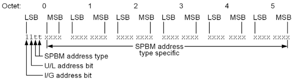
Figure 27-2—SPBM group MAC address—general format
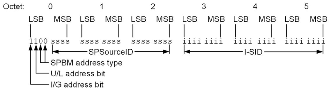
Figure 27-3—SPBM group MAC addresses—source rooted SPT
Figure 27-4 shows the format for group addresses assigned to a shared tree. Four bits of octet 2 are used to encode the Tie-Break Mask identifying the shared tree. If the same group address were to be used in two shared trees, forwarding loops could be created. The Tie-Break Mask is included in the group address so that the addresses used in different shared trees are distinct and forwarding loops are not created. The remaining bits are set to zero, leaving a substantial portion of the SPBM type 1 address space available for future use.
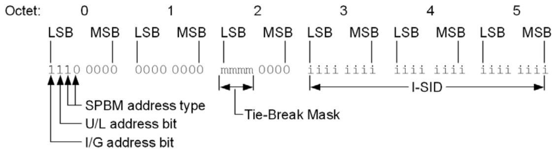
Figure 27-4—SPBM group MAC addresses—shared tree
The use of locally assigned group MAC addresses by SPBM mode does not affect the use of the same or different group MAC addresses for other VLANs. In addition to creating and managing the required FDB entries for each specific group address $( G A _ { S P B M } )$ for any given Base VID $( V _ { S P B M } , \mathrm { s a y } )$ that identifies an SPBM mode supported VLAN, an SPT Bridge using SPBM mode also manages the following entries:
If the FDB contains a static entry specifying Forward (for any Bridge Port) for the wildcard VID and any specific group MAC address not required by this subclause (27.15) then an entry specifying Filter (for all Bridge Ports) is also created for that group address and each Base VID supported by SPBM mode.
A Static Filtering Entry for All Group Addresses (for which no more specific Static Filtering Entry exists, (8.8.1) is created for each Base VID supported by SPBM mode, specifying that those addresses are to be filtered.
27.16 Backbone service instance topology management
An SPT Bridge using SPBM mode uses Dynamic Filtering Entries to explicitly permit unicast communication between stations, thus restricting that communication to the shortest path between those stations. SPBM mode also uses Static Filtering Entries, for each VLAN it supports, to create a multicast topology that is the pruned subset of the active topology that connects BEBs supporting the same backbone service instance using that VLAN.
Each SPT Bridge uses ISIS-SPB with the information calculated for the CIST and each SPT (27.6, 27.7, 27.8), and the following information from each BEB in the SPT Domain:
a) I-SID membership registration for each VLAN supported by SPBM mode.
For each of its Bridge Ports, for each I-SID and each SPT supporting the VLAN supporting that I-SID, the SPT Bridge computes the potential filtering control element values, Forward or Filter, for each port that is a Designated Port or Root Port. The potential control element specifies Forwarded if that port provides the shortest path to a BEB that has registered the VLAN, either directly (if that Bridge is in the same region) or via a Boundary Port (if the Bridge is in another region in the domain). A value of Filter is associated with each port that is an Alternate Port or Backup Port for the SPT.
The SPT Bridge creates a Static Filtering Entry for the VLAN’s B-VID and SPBM Group Address (27.15) for the I-SID and SPT, with a control element that specifies Forward if both the potential control element specifies Forward and the Port State variable forward (27.9) is True for the SPT for the port.
27.17 Equal cost shortest paths, ECTs, and load spreading
There can be several equal cost shortest paths between any given pair of Bridges, and the paths used by the SPTs in a given SPT Set are required to be symmetric (13.1), so the local tie-breaker [the lowest ISIS Local Circuit ID on the Bridge with the best (numerically least) SPB System Identifier (Clause 3)] is only used to select between links providing alternative connectivity between immediately adjacent Bridges. Equal cost tie breaking between paths that traverse different sets of Bridges is performed by calculating a unique identifier for each path that is independent of order used to compute trees. See 28.5 for a description of the Algorithm and the tie breakers.
The capability to support multiple VLANs using different ECTs allows a network administrator to choose different equal cost paths for different services by assigning services to selected VLANs. ECMP (Clause 44) provides the capability to spread load across equal cost shortest paths using a single SPBM VID.
A set of ECT Algorithms (28.8) is specified, each using a different tie breaker. The tie-breaking rules have been selected to provide a reasonable probability that different ECT Algorithms will choose different paths from a set of equal cost paths. ECT path selection can be controlled by selection of ECT Algorithm and by adjustment of Bridge Priorities.
SPB makes use of all nodes in the SPT region for forwarding.
27.18 Connectivity Fault Management for SPBM
Connectivity Fault Management (CFM) as specified in Clause 18 through Clause 22 provides capabilities useful in detecting, isolating, and reporting connectivity faults in VID-based service instances, backbone service instances, and TESIs. As with PBB-TE, SPBM disables flooding of frames with unknown destination address. This and other changes in behavior with SPBM require some modification to VLAN CFM functions. The modifications related to SPBM are summarized here.
In particular, this subclause summarizes SPBM considerations related to the following:
a) SPBM MA types (27.18.1)
b) SPBM MEP placement in a Bridge Port (27.18.2)
c) SPBM MIP placement in a Bridge Port (27.18.3)
d) SPBM modifications of the CFM protocols (27.18.4)
27.18.1 SPBM MA types
SPBM CFM uses three types of MA: SPBM VID MAs, SPBM path MAs, and SPBM group MAs.
An SPBM VID MA operates like a VLAN MA. For example, SPBM MEPs multicast CCM frames to all other MEPs and expect to receive CCM frames from all other MEPs in an SPBM VID MA. There are minor differences from VLAN MAs, primarily in the destination addresses used for CFM frames. SPBM VID MAs can be used to monitor and diagnose SPBM connectivity.
SPBM specifies two MA types for testing forwarding state installed by ISIS-SPB for specific addresses. In SPBM path MA CCMs are used to test the path for an individual destination MAC address between a pair of endpoints. This type of MA has only two MEPs, at two SPT Region boundary ports. An SPBM path MA is identified by a TE-SID comprising an ESP in each direction between the two endpoints. In an SPBM group MA CCMs are used to test a set of multicast trees used by a backbone service instance. This type of MA has multiple MEPs, each located at a CBP supporting the backbone service instance whose multicast trees are to be tested. An SPBM group MA is identified by the I-SID whose multicast trees it tests. The path taken by CCM frames depends on the current state of the network (i.e., paths are subject to rerouting triggered by topology changes). A CCM defect detected by an SPBM path MA or SPBM group MA may indicate a problem with the forwarding state for the MAC addresses being tested. This standard does not specify the mechanisms that would be necessary to support Loopback and Linktrace on an SPBM path MA or SPBM group MA since full Loopback and Linktrace coverage can be provided by an SPBM VID MA. Therefore, there are no MHFs associated with an SPBM path MA or SPBM group MA.
27.18.2 SPBM MEP placement in a Bridge Port
SPBM MEPs are always Up MEPs and can only be placed on CBPs as these correspond to the demarcation points of the SPT Region. The SPBM MEPs are placed between the Frame filtering entity (8.6.3) and the Port filtering entities (8.6.1, 8.6.2, and 8.6.4) in the VID space identified by the EISS Multiplex Entity (6.17). An SPBM VID MEP is placed in the same location as a VLAN MEP as shown in Figure 27-5.
Since SPBM path MEPs and SPBM group MEPs must only see traffic using specific addresses, these MEPs need to be further differentiated by the TESI Multiplex Entity (6.19). This locates an SPBM path MEP or SPBM group MEP so that it receives CCMs only from the other MEPs in its MA. Figure 27-5 also shows an example of an SPBM path MEP and SPBM group MEP on a CBP.
27.18.3 SPBM MIP placement in a Bridge Port
SPBM MIP creation is based on the algorithm described in 22.2.3. SPBM MIPs are created per identified VIDs on PNPs. Figure 22-9 depicts an example of a pair of SPBM MHFs on a PNP.
Figure 27-5—SPBM MEP placement in a CBP
27.18.4 SPBM modifications of the CFM protocols
27.18.4.1 Continuity Check protocol in an SPBM MA
The Continuity Check protocol is described in 20.1, and the corresponding state machines are presented in Clause 20. The modifications required to realize SPBM MAs include the following:
a) In the case of an SPBM VID MEP, the destination_address parameter is set to the group MAC address for the SPBM default I-SID (Table 9-3) for the Bridge on which the MEP is configured. In the case of an SPBM path MEP, the destination_address parameter is set to the MAC address indicated by the ESP-DA field of the ESP having in its ESP-SA field the MAC address of the MEP. In the case of an SPBM group MEP the destination_address parameter is set to the SPBM group MAC address assigned to the source MEP’s CBP for the SPBM group MA’s I-SID [item a) in 20.11.1].
b) In the case of ECMP with flow filtering, the flow_hash and time_to_live parameters are set [item e) in 20.11.1].
All other Continuity Check processes are the same as those for a VID-based MA.
27.18.4.2 Loopback protocol in an SPBM MA
The Loopback protocol is described in 20.2 and the corresponding state machines in Clause 20. The modifications required to realize the SPBM MA are summarized below:
a) To enable MIPs to selectively intercept LBMs that are targeting them, the PBB-TE MIP TLV (21.7.5) is inserted as the first TLV [item g) in 20.31.1] in an LBM. The format of the PBB-TE MIP TLV is described in 21.7.5 and is constructed as follows:
1) The MIP MAC address field contains the MAC address of the MIP to which the LBM is targeted [item b) in 12.14.7.3.2];
2) The Reverse VID field and Reverse MAC field are not used in SPBM.
b) An SPBM MHF forwards all received LBMs except those carrying a PBB-TE MIP TLV containing in their MIP MAC address field the MAC address of the MIP associated with that SPBM MHF [item f) in 20.28.1];
c) In the case of ECMP with flow filtering, the flow_hash and time_to_live parameters are set [item d) in 20.31.1].
NOTE—The MIP MAC address for an LBM does not have to be advertised by ISIS-SPB since it is only used locally to match the value provided in a PPB-TE MIP TLV.
All other Loopback processes are the same as those for a VID-based MA.
27.18.4.3 Linktrace protocol in an SPBM MA
The Linktrace protocol is described in 20.3 and the corresponding state machines in Clause 20. The modifications required to realize the SPBM MA are summarized as follows:
a) The LTMs transmitted by a MEP associated with an SPBM MA use as the destination_address parameter the MAC address indicated in the LTM management request [item c) in 12.14.7.4.2].
b) No special destination_address validation tests are performed by the ProcessLTM() procedure in the case of SPBM MAs [item c) in 20.47.1].
c) To identify a possible egress port, an SPBM MIP queries the FDB of its associated bridge using the destination_address and the vlan_identifier of the LTM as the parameters for the lookup (20.47.1.2). In the case of ECMP with flow filtering, the flow_hash value of the LTM is also used for the lookup, if required. For group addresses, LTMs can be further forwarded by SPBM MIPs even if the lookup identifies more than one Egress port.
d) In the case of ECMP with flow filtering, the flow_hash and time_to_live parameters are set [item d) in 20.42.1].
All other Linktrace processes are the same as those for a VID-based MA.
27.19 Using SPBV and SPBM modes
This subclause (27.19) provides one example topology of SPT Bridges using SPBV mode and one example topology of SPT Bridges using SPBM mode.
27.19.1 Shortest Path Bridging—VID
The primary advantage SPT Bridges operating in SPBV mode bring over spanning tree protocols is the more flexible shortest path forwarding. SPBV accomplishes this by using SPVIDs and VID translation (6.9) at SPT Region boundaries. All traffic within an SPT Region always takes a shortest path. Loops are prevented by never allowing traffic to be accepted on a non symmetric shortest path and enforced with loop prevention (13.17, 6.5.4.1).
An example campus network using SPBV is illustrated by Figure 27-6. The SPT Region contains eight SPT Bridges with two RST Bridges connected to the SPT Region. All VLANs within the SPT Region are supported by the SPT Bridges. The dashed lines represent the SPT for the SPVID of a Base VID (VID10) for which Access Bridge 1 is source (root of the SPT). The solid lines to the RST Bridges indicates spanning tree forwarding. VID translation from and to the respective SPVIDs occurs on the region boundary ports SPT Bridge D port 5 and SPT Bridge E port 3. SPT forwarding makes better use of a mesh network; however, it only will use a single path per Base VID. For example the Bridge D port 2 to Bridge B port 4 link is not used by access Bridge 1 because the ECT Algorithm has chosen paths through Bridge C. If another VLAN is supported in this network the recommendation is to use a different ECT Algorithm that could choose D-B over C-B by using an appropriate tie breaker (28.8).
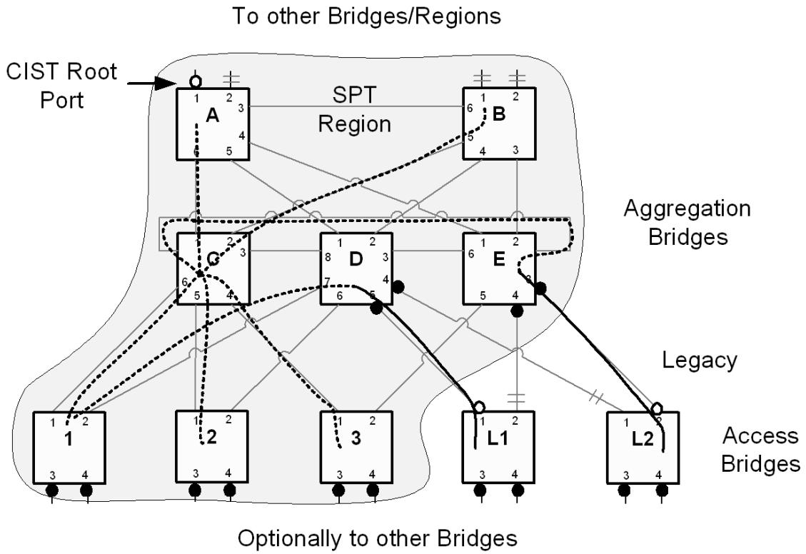
Figure 27-6—SPBV campus network example
ISIS-SPB uses SPB Hellos to establish adjacencies within the SPT region and BPDUs to establish peering with RST Bridges. BPDUs from legacy Bridges L1 and L2 will indicate that they are able to use RSTP. Therefore, RSTP would be enabled and SPB Hello would be transmitted periodically but dropped. The ports connected to the legacy Bridges are enabled and block according to RSTP logic.
SPT Bridges using SPBV mode use the same principles as MSTP to form a logical Bridge with a CIST root port on Bridge A, which has the best (numerically least) Bridge Identifier in the SPT Region. The CIST in Figure 27-6 is a spanning tree rooted on Bridge A (not illustrated).
a) The eight Bridges in the SPT Region have the same MCID (13.8) or Auxiliary MCID (28.9).
b) The CIST is computed in the SPT Region and maintains the spanning tree root costs (13.17).
c) SPT BPDUs are exchanged by the SPT Bridges within the SPT Region (13.17).
d) VLANs identified by other than the Base VIDs are supported by the CIST (13.17).
Legacy Bridges L1 and L2 can be aware of the SPB operation of Bridges but they only support RSTP and interface to the aggregation Bridges D and E using RST BPDUs. L1 and L2 learn from the received BPDUs that aggregation Bridge A is the Designated Bridge for VLAN 10 while a Bridge somewhere above the SPT region is the CIST Root for the network. Aggregation Bridge D receives traffic from L1 but uses an SPVID and the corresponding SPT from D to reach all nodes within the region and beyond. Normal learning of MAC addresses occurs.
Dynamic VLAN Registration capabilities are supported natively for Base VIDs by utilizing the link state to auto enable forwarding on intermediate Bridges. Referring to Figure 27-6, if access Bridge 1 and aggregation Bridge A were the only Bridges with VID 10 registered on their boundary ports forwarding would automatically be setup on aggregation Bridge C to complete the data path between Bridge 1 and Bridge A. Only Bridges configured with the Base VID, Bridge 1 and Bridge A require SPVIDs. MVRP for other VLANs is supported on the CIST.
MAC Address Registration (8.8.4) is supported for the Base VIDs as outlined in 28.10. Group addresses for Base VIDs are distributed in ISIS-SPB. At the region boundaries MMRP is required to propagate registration to and from the SPT Region.
Since the SPT Region follows very similar design rules as the MST Region, RSTP and STP interwork with both. SPB interworks with MSTP and other SPT Regions with MSTP.
27.19.2 Shortest Path Bridging—MAC
An example SPT Bridge network using SPBM mode is illustrated by Figure 27-7. The SPBM mode example network is divided into two major areas: the customer equipment area, which is owned by the “customer” and is connected to the SPT BEBs using C-tagged or S-tagged interfaces; and the SPT Region, which is owned by the backbone provider and interconnects to the customer equipment and possibly to other SPT Bridges. There is no visibility of either backbone topology or B-MAC addresses outside the SPT Region, and consequently connections to other SPB or PBB areas will be identical to those to customer equipment. While this is primarily leveraging the capabilities of the PBBN the emphasis is that the separation of the address spaces proved by the PBB encapsulation provided useful capabilities of scaling even larger enterprise or data center networks (DCNs) where bridging and delivery of optimized unicast and multicast frames on an S-VLAN basis is desired.
The interface between an IB BEB and a customer Bridge is a CNP of an I-Component as specified in 6.10. The interfaces between BEBs and BCBs and between BCBs and other BCBs are PNPs. In Figure 27-7, these interfaces are over LANs labeled S and B. All exterior interfaces from a SPT Bridge network using SPBM mode are over S, or C LANs; whereas all interior interfaces within a SPT Bridge network support appropriate segments of SPB SPTs, each set of which is identified by one Base VID per forwarding topology. Each individual SPT within a set is identified by the B-MAC address of its source Bridge. The S and C VLANs (exterior interfaces) are at the boundary between the SPT Bridge network and the attached customer networks.
Within the network example, BEBs, BCBs, and the SPTs for each Base VID are secured so that only the network administrator operating the SPT Bridge network can manage the reception, transmission, and relay of frames between BEBs and BCBs. The arbitrary physical network topology of the SPT Bridge network and the connectivity that it provides to support segregated instances of the MAC Service is designed and managed by the network administrator to meet bandwidth and service availability requirements at the CBPs and PIPs. Application of the service instance ingress and egress rules at these Ports in support of service instance selection and identification ensures that frames cannot be transmitted or received on any backbone service instance by any customer’s equipment without prior agreement with the administrator of the SPT Bridge network.
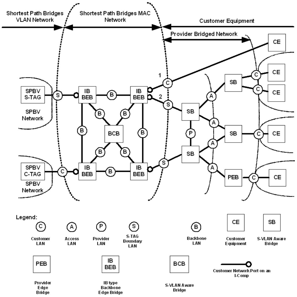
Figure 27-7—SPT Bridge Network using SPBM example
The active topology of the SPT Bridge network is separated from the active topology of the customer equipment area. This is accomplished by isolating the BPDUs for each customer network from the SPT Bridge network at the BEBs that surround the perimeter of the SPT Region. The ISIS-SPB LSPs and SPT BPDUs, that support the active topology of the SPT Bridge network, are only exchanged on PNPs and hence are not leaked into the customer bridged area.
B-MAC addresses are used to identify the destination BEB’s PIP. These B-MAC addresses are advertised by each BEB to all other BEBs and BCBs in the SPT Bridge area in LSPs as part of the IS-IS routing exchanges. I-SID instances associated with each PIP are also advertised using the same mechanism. To perform the encapsulation and de-encapsulation of service frames, BEBs use the connection identifier stored in the FDB (8.8) to correlate C-MAC addresses to B-MAC addresses. At startup, after convergence of ISIS-SPB, the BEBs are aware of the location of B-MAC addresses in the topology, but have not learned the C-MAC addresses yet. When the C-MAC address is unknown, the BEB encapsulates the service frames using an SPBM Group address which is analogous to the Backbone Service Instance Group address (26.4). This address is then multicast to the set of registered receivers that are those BEBs where that I-SID has been configured. The same holds true for the service frames having a group or broadcast destination address. An individual B-DA is used for forwarding unknown or group frames when the service is point-to-point and where the far end individual address is known. C-MAC addresses are learned by the provider BEB against the B-MAC address associated with the service interface on the BEB which sourced them (see Clause 25).
27.20 Security considerations
This clause contains no exceptional provisions for securing the operation of ISIS-SPB. ISIS has a number of optional capabilities which may be utilized. For example, ISIS-SPB does not prevent the use of the IS-IS Authentication TLV. If stronger security is required, IEEE 802.1AE MAC Security should be deployed on all SPT Bridge Ports, and the configuration of the controls provided by this standard to regulate the acceptance of spanning tree protocol information [e.g., restrictedRole and restrictedTcn (13.27.64, 13.27.65)] should be set to reflect the degree of trust (i.e., authorization) accorded to the mutually authenticated securely communicating peer Bridges. SPT BPDUs include a flag that indicates that the attached LAN is not considered to be a part of the transmitting Bridge’s SPT Region: this avoids one way participation in a region if one Bridge considers the authorization of another inadequate. Use of MAC Security in this way can ensure that only authenticated and authorized (i.e., trusted) Bridges participate in a region, as well as preventing unauthorized transmission of ISIS-SPB information or user data on LANs within the region.
28 ISIS-SPB Link State Protocol
Intermediate System to Intermediate System (IS-IS) is the link state routing protocol used for SPB (Clause 27). IS-IS is easily extended to carry the required Ethernet addresses, VLAN and Service membership information introduced by SPB. IS-IS is defined in ISO/IEC 10589:2002. When used for SPB, IS-IS has no IP dependencies. IS-IS also supports Multi-Topology (MT) and logical instances for easy virtualization of the link state protocol. This subclause specifies extensions to IS-IS for SPB. IS-IS extended for SPB will be referred to as ISIS-SPB. The SPB extensions are additive to IS-IS and do not preclude the IS-IS protocol being used for other purposes at the same time.
In VLANs that are configured to use SPB, ISIS-SPB controls forwarding (Clause 8) of individual and group addressed MAC frames. The Agreement Protocol (13.17), utilizes the ISIS-SPB link state database along with a synchronization mechanism carried in SPT BPDUs or SPB Hello PDUs. Locally on each Bridge, the Agreement Protocol logic is used to control the ISIS-SPB FDB updates and implement loop prevention logic. ISIS-SPB uses normal IS-IS procedures to update the link state database.
IS-IS uses SPB Hello PDUs and Link State PDUs (LSPs) to communicate between SPT Bridges. This section describes the relevant TLVs in the ISIS-SPB PDUs. Note that ISIS-SPB does not add any new PDU’s to IS-IS it extends the currently defined PDUs.
Figure 28-2 through Figure 28-12 illustrates the new TLVs and sub-TLVs for SPBV and SPBM. Note that SPBM, since it derives from PBB has the capability to indicate Service instance membership using the 24- bit I-SIDs. A default I-SID (I-SID 0x0000ff) maps to all SPT Bridges operating in SPBM mode allowing a default broadcast and group address capability for ISIS-SPB. The default I-SID is assigned to the default ECT Algorithm (LowPATHID, 28.7). I-SID group registrations via ISIS-SPB are similar to the MMRP capability but because they are delivered by IS-IS they involve no additional messaging. Group addresses are constructed by SPBM for each service instance/source and therefore do not require explicit advertisement.
The I-SID value of 0 is reserved by SPBM and is used as a deleted or free I-SID value in the TLV’s. This reserved value may be used to avoid reorganizing LSPs when only one or a few I-SIDs are changed. This provides an optimization by allowing actual deletion (shuffling of the LSP contents) to be decoupled from the ISIS-SPB updates triggered by topology changes. LSPs may be reorganized during periodic updates thereby minimizing impacts.
SPBV and SPBM will operate either within an IS-IS level 1, or an ISIS level 2. As a result the TLVs specified here may propagate either in level 1 OR level 2 LSPs. IS-IS SPBM implementations shall support level 1 and may support level 2 operations. Multi-level ISIS-SPB is, however, for further study.
NOTE—IS-IS supports point-to-point links and shared LANs; however, only point-to-point is considered for ISIS-SPB in this specification. A future revision may add shared media. Clause 13 SPB description allow both point-to-point links and shared media.
28.1 ISIS-SPB control plane MAC
ISIS-SPB makes no changes to the IS-IS control plane addressing principles. However, ISIS-SPB defines two further addresses for the propagation of LSPs besides the three addresses already reserved by ISO (see Table 8-13). ISIS-SPB differentiates itself from IS-IS for Ipv4 etc. by the contents of the SPB Hello PDUs. The most important differentiation is the NLPID value for SPB (0xC1) [Annex Q] which is carried in the SPB Hello protocols supported TLV and used to decide if a given adjacency should support SPB. ISIS-SPB carries this value in the Protocols Supported TLV (129) of IS-IS.
SPB operates either stand alone within an IS-IS instance, or shares an IS-IS instance and its adjacencies with other protocols as distinguished by the appropriate Network Layer Protocol Identifiers (NLPIDs). In order to accomplish this, ISIS-SPB may as one option use the same control plane MAC addressing as the other NLPIDs.
SPB does not advertise its NLPID on shared media interfaces.
28.2 Formation and maintenance of ISIS-SPB adjacencies
ISIS-SPB uses the IS-IS three-way handshake for IS-IS point-to-point adjacencies described in IETF RFC 5303 to form adjacencies when they can be formed. This subclause specifies the conditions under which they may be formed, and the conditions under which the link may be used for forwarding after an adjacency has formed.
a) The initial exchange of SPB Hello PDUs between a pair of IS-IS instances advertises the NLPID value(s) supported by each Bridge. If any NLPID values match, it is anticipated that an adjacency will be established to support the matched Network Layer Protocol(s).
This standard specifies subsequent behavior only for adjacencies which support SPB (NLPID value 0xC1). ISIS-SPB supports MTs, and if more than one topology is instantiated, the procedures below are applied independently to each topology instance.
b) The link supporting the adjacency is initialized to “SPB Operationally down.” This is signalled by setting the SPB Link Metric in the Link Metric Sub TLV (28.12.7) to the value $( 2 ^ { 2 4 } - 1 )$ . All SPB Link Metric values $< ( 2 ^ { 2 4 } - 1 )$ signify “SPB Operationally up,” and the value advertised is that to be used in path computation.
c) The SPB Hello PDUs exchange MCID and Auxiliary MCID (28.4) values to determine whether VLANs are consistently allocated to an operational mode. If a Bridge detects that neither its MCID nor its Auxiliary MCID match the adjacency’s MCID or Auxiliary MCID, then the adjacency cannot be put into service, and no further tests are performed until an acceptable match has been achieved.
d) After an acceptable MCID match is achieved, configuration consistency for each Base VID in the topology is verified. The SPB Base VLAN-Identifiers sub-TLV (28.12.4) carried in SPB Hello PDUs carries, for each Base VID supported:
The Base VID value;
— The ECT-ALGORITHM identifier (OUI or CID/Index) for that Base VID;
The SPB Hello Use-Flag (1-bit), set if this Bridge or any Bridge in the SPT Region is using this Base VID for traffic;
The M-Bit (1 bit), which indicates SPBM mode or SPBV mode.
Consistency is determined as follows:
If either the local end or the far end SPB Hello Use-Flag of the adjacency are set, then only if the respective Base VID, ECT-ALGORITHM, and Mode bits match exactly is “matched” set for that Base VID.
If both local end and far end SPB Hello Use-Flags are clear, then “matched” is set (to allow maintenance of the adjacency during ECT Algorithm and mode reassignment).
Only if “matched” is true for all Base VIDs in the topology is the link supporting the adjacency set to “SPB Operationally up,” and usable for forwarding.
e) Once the link supporting the adjacency has advanced to “SPB Operationally up” as above, a Bridge shall only modify the ECT-ALGORITHM or Mode bit associated with any Base VID when both the local end and far end SPB Hello Use-Flags are clear. A Bridge shall not modify the ECT-ALGORITHM or Mode bit associated with any Base VID when either local or far end SPB Hello Use-Flag is set. To do so is indicative of a serious error condition.
f) If a Bridge detects that an adjacent Bridge has altered its advertisement of the ECT-ALGORITHM or Mode bit associated with any Base VID while either the local or far end SPB Hello Use-Flags is set, it shall declare the link supporting the adjacency “SPB Operationally down.”
NOTE—If the error condition arises because of aberrant behavior by a single Bridge, the condition described will be detected by all its adjacencies, and the behavior specified will cause the aberrant Bridge to be isolated from the SPT Region. This is the least damaging mitigation of such a condition.
28.3 Loop prevention
The Group Address FDB entries for SPBV and SPBM are under the control of the ISIS-SPB database exchange. Group address entries can be ensured to be loop-free when two neighboring Bridges agree never to install potentially loop-forming state derived from an unsynchronized topology in the FDB (13.17, 6.5.4.1). This occurs by allowing ISIS-SPB to exchange link state messages and remove any older FDB entries that are no longer valid to any destination. Native IS-IS does not have a method for synchronizing the removal of state from the forwarding but it does have a method for synchronizing databases. ISIS-SPB augments this by using a digest of the database and adding the FDB condition. ISIS-SPB needs two modifications from regular IS-IS.
a) ISIS-SPB needs to remove any potential loop causing forwarding entries if its link state database is not synchronized with its neighbor Bridges.
b) ISIS-SPB needs to synchronize with its neighbors Bridges before installing Group Address FDB entries to prevent any potential loops.
The Agreement Protocol (13.17) specifies how this applies to ISIS-SPB.
28.4 The Agreement Digest
The Agreement Digest specified in this clause includes a Computed Topology Digest used to determine whether a neighboring Bridge is operating with identical network topology information and thereby determine whether frames may be safely forwarded to the neighbor.
The Agreement Digest field (Figure 28-1) comprises six elements:
The Agreement Digest Format Identifier
The Agreement Digest Format Capabilities
The Agreement Digest Convention Identifier
The Agreement Digest Convention Capabilities
The Agreement Digest Edge Count
— The Computed Topology Digest
The Agreement Digest is carried as a structured 32-byte field in the ISIS-SPB Digest sub-TLV. Byte 1 is the most significant, Byte 32 is the least significant byte.These and all parameters carried in ISIS-SPB TLVs and sub-TLVs are encoded using the “big-endian” convention, in which lower numbered bits within each byte (those to the left) have higher significance.
<table><tr><td></td><td>Octet</td><td>Length</td></tr><tr><td>Agreement Digest Format Identifier</td><td>1</td><td>4 bits</td></tr><tr><td>Agreement Digest Format Capabilities</td><td>1</td><td>4 bits</td></tr><tr><td>Agreement Digest Convention Identifier</td><td>2</td><td>4 bits</td></tr><tr><td>Agreement Digest Convention Capabilities</td><td>2</td><td>4 bits</td></tr><tr><td>Agreement Digest Edge Count</td><td>3-4</td><td>2</td></tr><tr><td>Reserved (set to 0)</td><td>5-12</td><td>8</td></tr><tr><td>Computed Topology Digest</td><td>13-32</td><td>20</td></tr></table>
Figure 28-1—Agreement Digest field format
28.4.1 Agreement Digest Format Identifier
The Agreement Digest Format Identifier (4 bits) is carried in the most significant 4 bits of Byte 1 of the Agreement Digest field. Its purpose is to allow alternative digests to be defined at some time in the future. This release of the standard defines Digest Format 0. All future upgrades to the standard protocol will require recipients to be able to receive and process digests of this format.
The Agreement Protocol (13.17) will not declare a topology match if the recipient does not support the Format value of this field, but otherwise it will operate as normal, so that the transmitter will receive an indication of the Digest Format Identifier and Capabilities of the receiver as a result of normal protocol operation.
28.4.2 Agreement Digest Format Capabilities
The Agreement Digest Format Capabilities (4 bits) is carried in the least significant 4 bits of Byte 1 of the Agreement Digest field. Its purpose is to allow alternative digest Formats to be defined and advertised at some time in the future. In this version of the standard it is transmitted as value 0 and ignored on receipt.
28.4.3 Agreement Digest Convention Identifier
The Agreement Digest Convention Identifier (4 bits) is carried in the most significant 4 bits of Byte 2 of the Agreement Digest field. Its purpose is to advertise the set of loop-free forwarding rules, for which the link state database information identified by the Digest acts as input, which are currently in use by the transmitter (13.17). The following rules are defined in this version of the standard:
— 1. indicates no digest match. Digests are exchanged but match is not required. Configured as off (Clause 17).
- means the transmitter will continue loop-free forwarding of both multicast and unicast traffic either only after any change which occurs has been reflected in matched digests (strict agreement); or up to the limits of change specified by the rules in this version of the standard. This is the default. Configured as loopFreeBoth (Clause 17).
- means the transmitter will continue loop-free forwarding of multicast traffic up to the limits of change specified by the rules in this version of the standard, and will continue forwarding of unicast traffic unconditionally. Configured as loopFreeMCastOnly (Clause 17).
NOTE—While it is recommended that all Bridges use the same convention, Bridges operate independently and the conventions can be different on individual Bridges. For loopFreeBoth and loopFreeMCastOnly as indicated, a Bridge may block all the respective traffic on change or allow “safe” traffic during change. Individual Bridges can have different definitions of “safety” applied to the forwarding allowed during digest mismatch.
28.4.4 Agreement Digest Convention Capabilities
The Agreement Digest Convention Capabilities (4 bits) is carried in the least significant 4 bits of Byte 2 of the Agreement Digest field. Its purpose is to advertise the set of loop-free forwarding rule conventions which are understood by the transmitter. The value 0 declares that the transmitter understands conventions 1 to 3 (above). Bridges conforming to this version of the standard transmit the value 0 and ignore this field on receipt.
28.4.5 Agreement Digest Edge Count
The Agreement Digest Edge Count (16 bits) is an unsigned integer carried in Byte 3 and Byte 4 of the Agreement Digest field. Its purpose is to provide one component of the Agreement Digest, which is simple to compute and powerful in detecting many simple topology mismatches.
This value is the sum modulo $2 ^ { 1 6 }$ of all Edges in the SPB topology. Each point-to-point physical link is counted as two Edges, corresponding to its advertisement by ISIS-SPB in an LSP flooded from either end of the link.
If more that one ISIS-SPB topology is configured, the Agreement Digest Edge Count accumulates all Edges in all configured topologies. If Edges are absent in a particular topology, they have the value 0 for this summation.
NOTE—MT SPB allows different Link Metrics to be used in different topologies. The Agreement Digest format specified here can only achieve a match between topologies when exactly the same set of Bridges are present in all topologies but the requirement that MCIDs match for all Bridges in an SPT Region means that this is not an additional constraint.
28.4.6 The Computed Topology Digest
The overall procedure for constructing the Computed Topology Digest is to
Form a signature of each Edge in the topology by computing the MD5 hash (IETF RFC 1321) of the significant parameters of the Edge, as defined below.
— Compute the Digest as the arithmetic sum of all Edges in the topology.
If more than one topology is declared in ISIS-SPB, the Computed Topology Digest covers all topologies declared, and this single value is advertised in the ISIS-SPB Digest sub-TLV. The SPB Digest sub-TLV is carried within the MT-Port-Cap TLV [IETF RFC 6165] with the MTID value of 0, which in turn is carried in an SPB Hello PDU.
NOTE 1—MD5 is widely reported to be cryptographically weak. This is not relevant in this application. What is required is a function exhibiting good avalanche properties such that signatures with potentially very similar input parameters have an infinitesimal probability of collision.
NOTE 2—This strategy allows the Digest to be incrementally computed when the topology changes, by subtracting the signatures of vanished Edges from the Digest and adding the signatures of new Edges. In general, the signature of an Edge therefore needs only to be computed once, when it is first advertised.
The input message to the MD5 hash for each Edge is constructed by concatenating the following fields in order, with the first field being the beginning of the message.
a) The Bridge Identifier (13.26.2) of the Bridge advertising the Edge with the greater Bridge Identifier value (8 bytes).
b) The Bridge Identifier of the Bridge advertising the Edge with the lesser Bridge Identifier value (8 bytes).
c) A variable number of 8-byte 3-tuples, one 3-tuple for each MTID (Clause 3) declared in ISIS-SPB. The 3-tuples are declared in descending order of MTID value, with the largest MTID declared first.
Each 3-tuple is constructed by concatenating the following fields in the order below:
d) A 2-byte field containing the 12-bit MTID value [IETF RFC 5120] in the least significant bits, with the most significant 4 bits of the field set to zero.
e) The SPB Link Metric [item c) in 12.25.6.1.2] for the Edge in this topology that has been advertised by the Bridge with the greater Bridge Identifier value (3 bytes)
f) The SPB Link Metric for the Edge in this topology that has been advertised by the Bridge with the lesser Bridge Identifier value (3 bytes)
If an Edge is not present in a topology, its SPB Link Metric is set to zero in that topology.
The value of the Computed Topology Digest is the arithmetic sum of all of the signatures returned by presenting every Edge message to MD5, treating the signature as an unsigned 16-byte integer and accumulating into a 20-byte integer. Every physical link is seen as two Edges, one advertised by each Bridge comprising the adjacency, and formally the Computed Topology Digest includes both.
NOTE 3—Although the Computed Topology Digest contains signatures for both Edges associated with each link, the construction defined above means that these are always identical. An implementation may choose to compute a single signature per link, and then double it before accumulating it into the Computed Topology Digest.
The value of the Computed Topology Digest is placed in Bytes 13 to 32 of the Agreement Digest field for transmission in the ISIS-SPB Digest sub-TLV.
Bytes 5 to 12 of the Agreement Digest field are unused in this version of this standard. They are set to zero on transmission and ignored on reception.
28.5 Symmetric shortest path tie breaking
When performing shortest paths computation there may be several equal cost shortest paths between the same Bridge pairs (27.17). In order to meet the congruency requirements, SPB requires that the computation produces a deterministic unique shortest path per SPT set independent of order or direction of computation.
The SPB symmetric (Clause 3) shortest path tie-breaking algorithm needs to be accurately specified or different versions of SPB would compute different SPTs. SPB requires symmetry and congruence in its unicast and multicast routing so this section specifies unambiguously how the algorithms defined for the base specification operate and how they may be extended in the future.
NOTE—Exploration of path computation that produces various types of ECTs is beyond the scope of this standard.
Two mechanisms are used to provide for symmetric and congruent SPT calculation. The first mechanism addresses the possibility that different ends (nodes) of an adjacency advertise different values for the SPB Link Metric (28.12.7). To maintain determinism, the SPB shortest path calculation always uses the maximum of the two advertised SPB Link Metric values when accumulating path costs. The second mechanism addresses the situation in which two equal cost paths are found. To maintain determinism in this case, a tie-breaking algorithm is required that achieves the same result regardless of order of computation.
SPB is designed to support many tie-breaking algorithms for ECTs, and SPBM can assign traffic by I-SID to different B-VIDs assigned to different ECTs. SPB defines one required tie-breaking algorithm and an open framework for the creation of a very large number of additional algorithms. As part of the base standard, a number pre-defined tie-breaking algorithms are described using this framework with extensions for expansion in the future.
SPB accomplishes basic equal cost tie breaking by logically assigning a computation-order-independent identifier to each possible equal cost shortest path that it computes. This tie breaking is symmetric because it is independent of which direction the selection is done and it preserves reverse path congruency. This is referred to as the Path Identifier (PATHID). A PATHID is defined as the sorted list (ascending lexicographic order) of Bridge IDs that the path traverses including the endpoints.
When there are different equal cost shortest paths output by the SPF computation, each of them will have a unique PATHID. The PATHID for each distinct path will be the same whichever Bridge computes that PATHID. The PATHID will be the same for both the forward and reverse of a path (because they are sorted lists of Bridge-IDs). PATHIDs may be ranked and compared by successively comparing the sorted list of Bridge-IDs they contain. PATHID A is ranked “less than” PATHID B if it contains fewer Bridge-IDs:
$$
\text { E.g.: } \{9, 1 5, 2 2 \} < \{7, 8, 9, 1 0, 2 2 \}
$$
PATHID A is ranked “less than” PATHID B (of equal length) if its i’th Bridge-ID is less than B’s i’th Bridge-ID and all other Bridge-IDs up to the i’th are equal (lexicographic order).
$$
\text { E.g.: } \{9, 1 5, 2 2, 9 9 \} < \{9, 1 5, 2 2, 1 0 0 \}
$$
Both SPBV’s and SPBM’s default tie-breaking algorithm picks the equal cost path with the lowest PATHID as defined in the above ranking.
The above algorithm can be easily implemented efficiently by simply back tracking the two or more competing equal cost paths and picking the path which has the minimum PATHID between the fork and join points of the competing paths. A path selected in this manner will also be part of any longer shortest paths which transit the fork and join points, and so intermediate resolution of shortest path permutations can be performed and the state for discarded permutations need not be carried forward.
The Bridge Priority by default is the middle value equal to 8 of the 4-bit priority in the most significant part of the 2-byte field [8 * 4096 = 32768 middle of the priority range] on all Bridges, and so does not affect the tie-breaking results. Bridge Priority can be tuned by the operator and will therefore affect the pre-defined tiebreaking algorithm(s) in a deterministic manner.
28.6 Symmetric ECT framework
Each tie-breaking method is uniquely identified by an ECT Algorithm. The ECT Algorithm is a 32-bit number that contains an OUI or CID and an index. This document specifies an initial set of SPB ECT Algorithms together with a framework for a large number of other algorithms. The OUI or CID allows organizations to specify and manage their own algorithms and behaviors and to document them independently either through the IEEE, or through other SDOs, or to keep them proprietary/experimental should they desire. The different SPB ECT Algorithms defined in this document use the IEEE 802.1 OUI (00-80-C2) and Index values 1 through 16 while one additional non-ECT spanning tree algorithm is defined with Index value 0.
The ECT Algorithm is unique for an SPT Set. One or more Base VIDs may be associated with an ECT Algorithm; and this association is advertised both in LSPs to all other Bridges in the SPT region and also is exchanged in the SPB Hellos. A Base VID should not be used within the SPT region until all Bridges agree on the relationship. Temporary disagreement between the Base VIDs assigned is expected and permitted between Bridges as Base VIDs with new ECT Algorithms are configured. Disagreements are allowed when the Base VIDs is not in use. Base VIDs may share the same ECT Algorithm regardless of mode.
In SPBM, an I-SID is associated with a Base VID and thus by inference with an ECT Algorithm as well. This permits an operator to assign traffic to a certain ECT-ALGORITHM and to move it as required to achieve a degree of traffic balancing. In SPBM mode this Base VID is the B-VID directly.
In SPBV mode the Base VID shall be used to lookup and find the proper SPVID for the source under consideration during the setting of VLAN Registration Entries. A VLAN supported by SPBV can be forced to use the spanning tree of the IST in cases where the Bridges do not agree on the configuration or are short on SPVID resources.
Bridges must consider all SPT sets and populate forwarding even if they do not define a VID. An ECT Algorithm can be defined to operate using only data already advertised by ISIS-SPB (for example the Low and High PathID algorithms), or, it may require additional tuning parameters that cannot be foreseen. To accommodate a future ECT Algorithm need for tuning parameters SPB supports the concept of Opaque ECT data.
To allow for nodal- and link-based ECT behavior in future requirement the Opaque ECT data may be advertised under both SPB nodal and/or link data. The Opaque ECT data begins with the 32-bit ECT-ALGORITHM identifier but the remainder of the data format is specific to future ECT Algorithms and is therefore opaque to this document.
An example use of this framework could be as follows. Consider the tie breaking that can be done by using a minimum sum over a secondary link metric and a hash-based but deterministic assignment of such secondary metrics to every link in the network. Further consider these secondary link metrics as tunable. Initially a new value for this ECT Algorithm is assigned and registering it with the appropriate numbering authority for the OUI or CID. The hash functions that create the secondary link metrics based for example on the two Bridge-IDs at each end of the link, could be defined. Then a format for a 32-bit opaque secondary metric could be defined which would be advertised as opaque data under the link data and prefixed with the ECT-ALGORITHM index for the new tie breaker. Migration to this new tie breaker would proceed in a manner consistent with any ECT Algorithm (28.9).
28.7 Symmetric ECT
In the case of multiple equal cost paths, multiple ECTs may be computed, in fact most efficient shortest path computations like Dijkstra actually produce all shortest paths from a root, i.e., an SPF tree, and different unique trees emerge depending on the tie breaking employed at the branch points. These different trees are distinguished in the forwarding plane by using SPVIDs (SPBV) or B-VIDs and B-MAC SAs (SPBM) for each “active topology”. In order to be repeatable a unique tie breaker (ECT Algorithm) is chosen for each SPT set as described in 28.5. Typically a small number of B-VIDs would satisfy most requirements for equal cost routes in the case of SPBM.
SPBV and SPBM support a set of symmetric (Clause 3) equal cost paths between any pair of Bridges for a given SPB instance/MTID. The algorithms are identified by the ECT Algorithm using the IEEE 802.1 OUI=00-80-C2 and with Index values 0..16. Index value 0 is somewhat special in that it relates the VID used for the CIST and is not a shortest path algorithm but is instead the spanning tree algorithm. The remaining algorithms are shortest path algorithms: The LowPATHID algorithm (index = 1) is the default SPT path computation tie breaker. SPB uses LowPATHID as the default SPT tie-breaking algorithm. SPB can use any alternate tie-breaking algorithm for another ECT when it is configured. The other defined algorithms use a computed shuffle of the LowPATHID algorithm. For example the HighPATHID ECT-ALGORITHM=<OUI=00-80-C2:index = 2> is just a rank inversion, which ones-complements the Bridge-IDs prior to doing the same comparisons as the LowPATHID algorithm. The remaining 14 pre-defined algorithms have indexes 3..16 and are defined in terms of a bit mask that they XOR the Bridge-IDs with prior to finding the minimum PATHID. Since they XOR over all 8 bytes, which includes the Bridge-Priority and the SPB System Identifier, these algorithms can be tuned in deterministic ways by adjusting the
Bridge-Priority. SPBM may advertise a Base VID for each of these unique symmetric shortest paths through the ECT SPB Instance sub-TLV (28.12.5).
SPB assigns a unique ECT Algorithm to a Base VID in the Base VID sub-TLV (28.12.4) and the SPB Instance sub-TLV (28.12.5). To allow migration between different ECT Algorithms, further ECT Algorithm and Base VID bindings may be advertised, unused, without interfering with the operation of currently used ECT Algorithms and Base VIDs. Once Bridges are configured to support the new ECT Algorithm and share a consistent Base VID for this algorithm, the algorithm may then be used by mapping I-SIDs to the Base VID for the desired ECT Algorithm.
SPBV also assigns a unique Base VID to each ECT Algorithm; however, the actual data path VID used depends on the source. Therefore, an SPVID shall be specified in the SPVID field in conjunction with the Base VID and ECT Algorithm in the SPB Instance sub-TLV. A similar procedure can be used with SPBV to introduce a Base VID that would not carry traffic until fully configured. Then services could be switched to the new VLAN. This is no different than introducing a new VLAN on RSTP for example.
28.8 ECT Algorithm details
This standard defines a set of symmetric ECT Algorithms used to calculate SPT Sets for SPBV or SPBM VLANs and one ECMP ECT Algorithm (44.1.2) used to calculate SPTs and shared trees for ECMP (Clause 44).
Each of the symmetric ECT-ALGORITHM values is formed using the OUI=00-80-C2 and the Index=1..16. An Algorithm Mask is specified for each Index, and is exclusive-ORed with each octet of each of the Bridge Identifiers (2 octet Bridge Priority concatenated with the 6 octet SPB System Identifier) to generate Masked Bridge Identifiers for each of the candidate paths. Given any two paths, the one chosen for a given ECT Algorithm has the lowest PATHID formed from the ranked masked Bridge Identifiers, which will necessarily include a lowest masked Bridge Priority, excluding those common to both paths. This comparison gives the greatest weight to the (masked) Bridge Priority of each Bridge Identifier, allowing the path selection to be managed/tuned without creating additional identifiers or identifier components for each Bridge. The ECT-ALGORITHM values and corresponding Masks and their effects, in terms of prioritizing path selection by Bridge Priority are as follows:
Table 28-1—Bridge Priority Masking
<table><tr><td>ECT-ALGORITHM</td><td>Algorithm MASK</td><td>Effect of using MASK on priority nibble</td></tr><tr><td>00-80-C2-01</td><td>0x00</td><td>The selected path includes Bridge with best (numerically lowest) Bridge Identifier after masking. In this case the masking 0x00 no effect and original administered Bridge priority values apply. When Bridge priority value is equal for two Bridge identifiers the lower system identifier determines the priority.(0,1,2,3,4,5,6,7,8,9,10,11,12,13,14,15).</td></tr><tr><td>00-80-C2-02</td><td>0xFF</td><td>The selected path includes Bridge with best priority (numerically lowest) Bridge Identifier after masking. In this case the masking 0xFF reverses the original administered Bridge priority values. When Bridge priority value is equal for two Bridge identifiers the lower system identifier determines the priority.(15,14,13,12,11,10,9,8,7,6,5,4,3,2,1,0). Read vector as administered priority 0 equals 15, administered priority 15 equals 0 and so on.</td></tr><tr><td>00-80-C2-03</td><td>0x88</td><td>Bridges with Bridge Priority 8 will be treated as best priority for path selection, followed by Bridge Priorities of 9, 10, 11, and so on.(8,9,10,11,12,13,14,15,0,1,2,3,4,5,6,7). Read vector as administered priority 0 equals 8, administered priority 8 equals 0.</td></tr><tr><td>00-80-C2-04</td><td>0x77</td><td>Bridges with Bridge Priority 7 will be treated as best priority for path selection,followed by Bridge Priorities of 6, 5, 4, and so on.(7,6,5,4,3,2,1,0,15,14,13,12,11,10,9,8). Read vector as administered priority 0equals 7, administered priority 7 equals 0.</td></tr><tr><td>00-80-C2-05</td><td>0x44</td><td>(4,5,6,7,0,1,2,3,12,13,14,15,8,9,10,11)</td></tr><tr><td>00-80-C2-06</td><td>0x33</td><td>(3,2,1,0,7,6,5,4,11,10,9,8,15,14,13,12)</td></tr><tr><td>00-80-C2-07</td><td>0xCC</td><td>(12,13,14,15,8,9,10,11,4,5,6,7,0,1,2,3)</td></tr><tr><td>00-80-C2-08</td><td>0xBB</td><td>(11,10,9,8,15,14,13,12,3,2,1,0,7,6,5,4,)</td></tr><tr><td>00-80-C2-09</td><td>0x22</td><td>(2,3,0,1,6,7,4,5,10,11,8,9,14,15,12,13)</td></tr><tr><td>00-80-C2-0A</td><td>0x11</td><td>(1,0,3,2,5,4,7,6,9,8,11,10,13,12,15,14)</td></tr><tr><td>00-80-C2-0B</td><td>0x66</td><td>(6,7,4,5,2,3,0,1,14,15,12,13,10,11,8,9)</td></tr><tr><td>00-80-C2-0C</td><td>0x55</td><td>(5,4,7,6,1,0,3,2,13,12,15,14,9,8,11,10)</td></tr><tr><td>00-80-C2-0D</td><td>0xAA</td><td>(10,11,8,9,14,15,12,13,2,3,0,1,6,7,4,5)</td></tr><tr><td>00-80-C2-0E</td><td>0x99</td><td>(9,8,11,10,13,12,15,14,1,0,3,2,5,4,7,6)</td></tr><tr><td>00-80-C2-0F</td><td>0xDD</td><td>(13,12,15,14,9,8,11,10,5,4,7,6,1,0,3,2)</td></tr><tr><td>00-80-C2-10</td><td>0xEE</td><td>(14,15,12,13,10,11,8,9,6,7,4,5,2,3,0,1)</td></tr></table>
NOTE 1—In these algorithms, the Algorithm Mask is applied to all octets of each Bridge Identifier. Thus if two alternative paths include only Bridges with one or a few Bridge Priorities, the Algorithm Mask will still reorder their priorities for inclusion on the path as it acts on the rest of the SPB System Identifier component of the Bridge Identifier field.
NOTE 2—If the two priority bytes in the 8-byte Bridge Identifier are all equal, then all Bridges have equal priority and ECT-ALGORITHM values 00-80-C2-01 and 00-80-C2-02 are exactly Low and High PATHID as described in 28.5.
28.9 ECT Migration
For orderly migration, each Base VID to ECT Algorithm assignment also has associated flags indicating active usage of the Base VID by services. The Use-Flag in the SPB Base VLAN-Identifiers sub-TLV (28.12.4) indicates a Bridge’s awareness of use of the Base VID somewhere in the SPT Region, and the Ubit in the SPB Instance sub-TLV (28.12.5) indicates local use of this Base VID. The Use-Flag in the SPB Base VLAN-Identifiers sub-TLV is carried in the SPB Hello PDU, and is set once the Bridge advertising the algorithm has started either using or seeing the use of that ECT-ALGORITHM. ISIS-SPB enforces the following rules with respect to ECT Algorithms and their usage in order to protect the SPB network from outages created by incorrect configuration. If neighbors disagree on a Base VID to ECT-ALGORITHM assignment, then use of the adjacency for SPB traffic is permitted (i.e., the SPB Link Metric may be set less than $2 ^ { 2 4 } - 1 )$ ) only if both neighbors’ Use-Flags associated with the Base VID are cleared (28.2).
If a new ECT Algorithm is implemented in all Bridges of an SPT Domain and intended to be used by a Base VID, then the assignment of the Base VID to the new ECT-ALGORITHM with Use-Flag cleared is first configured in the SPT Domain on a Bridge by Bridge basis. As soon as this configuration is complete, services (I-SIDs in SPBM or SPVIDs in SPBV) may be assigned to the given Base VID, which causes the local U-bit to be set, which will in turn cause the Use-Flag to be set for the given Base VID.
SPBV and SPBM have different migration capabilities after the introduction of a new ECT Algorithm. The following subclauses describe how SPBV and SPBM use a newly introduced ECT Algorithm.
28.9.1 Use of a new ECT Algorithm in SPBV
A new ECT Algorithm, which is implemented by each Bridge of an SPT Domain, gets to be used if it is configured to support a VLAN. In SPBV mode, the application of a new ECT Algorithm typically coincides with the introduction of a new VLAN supported by SPBV. That is, the Base VID of the new VLAN is assigned to the new ECT-ALGORITHM in the SPB Hello PDU Base VID and SPB Instance sub-TLVs (28.9). ISIS-SPB then allocates (27.10) the SPVIDs necessary for the support of the new VLAN. To support in-service upgrade from one set of VID / ECT Algorithm allocations to another, SPT Bridges allow graceful configuration of those services. Provided there is an operating SPBV or SPBM VLAN in a region, SPT Bridges can be configured within the Region for a new VLAN on a Bridge by Bridge basis. As long as the SPT Region is connected the Bridges supporting the new VLAN do not need to be directly connected. Intermediate Bridges are capable of populating forwarding without terminating services allowing them to participate in the VLAN.
The migration of a VLAN from an old ECT Algorithm to a new ECT Algorithm can be performed by the reassignment of the Base VID of the VLAN. That is, the Base VID is assigned to the new ECT-ALGORITHM instead of the old ECT-ALGORITHM on a Bridge by Bridge basis. In SPBV the forcing of one of the Bridges Base-VIDs to use the spanning tree algorithm as opposed to another algorithm forces all of the Bridges in the SPT region using that Base VID to spanning tree. Migration can then proceed to the new Base VID assignment until the last Bridge is configured to use the new ECT-ALGORITHM. The new assignment is then propagated in SPB Hello PDU Base VID and SPB Instance sub-TLVs (28.9) by ISIS-SPB within the SPT Domain. As soon as each SPT Bridge is configured with the Base VID assignment to the new ECT-ALGORITHM, the spanning tree assignment on the last Bridge is cleared.
NOTE 1—ISIS-SPB automatically performs the allocation and release of SPVIDs during the migration. The SPVIDs allocated for the Base VID old ECT-ALGORITHM assignment are released as soon as the assignment has been broken. These SPVIDs might be then allocated for the Base VID new ECT-ALGORITHM assignment. That is, there is no need for additional SPVID allocations if a Base VID supported by SPBV is migrated from an old ECT-ALGORITHM to a new one.
NOTE 2—SPBV does not support hitless migration. That is, the migration of a VLAN from an old ECT-ALGORITHM to a new ECT-ALGORITHM may cause traffic outage.
28.9.2 Use of a new ECT Algorithm in SPBM
SPBM offers the ability to map I-SIDs to Base VIDs as a load balancing option. In topologies with multiple equal cost paths the ability to spread traffic on a per I-SID basis comes from using the Base VIDs with different algorithms as specified in this clause.
When an I-SID is configured to be associated with a Base VID, that Base VID shall be consistently associated with the same ECT-ALGORITHM throughout the SPT Domain. Once at least one I-SID has been assigned to a Base VID the U-bit is set and advertised in subsequent LSPs, which also causes the Use-Flag to be set in SPB Hello PDUs.
SPBM supports in-service migration of an I-SID from an old ECT Algorithm to a new ECT Algorithm supported by each Bridge of an SPT Domain. In order to accomplish this, two complete Base VIDs must be configured in the SPT Domain. Then an I-SID under migration can be assigned to two Base VIDs at the same time: the old Base VID (old ECT-ALGORITHM), and the new Base VID (new ECT-ALGORITHM). The U-bit (in the SPB Instance sub-TLV, 28.12.5) is set by the advertising Bridge when there is at least one service using this VID. This propagates throughout the SPT domain, and any Bridge seeing at least one Ubit set in received LSPs (signifying that the indicated Base VID is being used by a service somewhere) sets the Use-Flag in its SPB Base VLAN-Identifiers sub-TLV (28.12.4).
I-SIDs will have originally been configured to be associated with the old Base VID (28.12.10). No filtering entry is set for the new Base VID in the FDBs as there is no Transmitter set on the new Base VID yet. I-SIDs can be configured to be associated with the new Base VID. Care must be taken to ensure the new Base VID is configured in all the required places. When a particular I-SID has been added to a new Base VID, ISIS-SPB detects that the I-SID is now associated with two Base VIDs and at each location that I-SID may receive traffic on either Base-VID. During this period individual addresses are available under both Base VIDs. The setting of the R and T bits still determines whether the group addresses are populated for each Bridge supporting that I-SID in either Base VID. In other words the same rules for a single Base VID are followed but two base VIDs are temporarily in use for received traffic. Traffic is “rolled” from the old Base VID to the new one by administrative reassignment of the I-SID at each service end-point from the old to the new B-VID. This can be an atomic action, and so at any instant only one Base VID will be used by any service originating frames. The association of the I-SID to the old Base VID is removed once all I-SIDs are configured to one Base VID. Furthermore, if this is the last I-SID removed from a Base VID the U-bit is cleared (in the SPB Instance sub-TLV) for the old Base VID to ECT-ALGORITHM assignment. Eventually the Use-Flag carried in the SPB Hello PDU will be cleared when all the Bridges have been configured.
28.10 MAC address registration
ISIS-SPB creates MAC Address Registration Entries (8.8.4) for group addresses in order to reach the members of a group. The group addresses are locally administered in case of SPBM (27.16), thus, they are only significant inside the SPT Region.
ISIS-SPB also installs MAC Address Registration Entries for universally administered group addresses as they might be used by SPBV. Furthermore, ISIS-SPB provides interworking with MMRP at the Boundary Ports of an SPT Region. That is, ISIS-SPB interprets MMRPDUs received at a Boundary Port and assembles the proper ISIS-SPB TLVs in order to advertise the corresponding MAC address registration inside the SPT Region. Furthermore, ISIS-SPB assembles and issues MMRPDUs on Boundary Ports if MAC address registration needs to be propagated outside of the SPT Region.
When an MMRPDU is received on a Boundary Port, ISIS-SPB disseminates the registration by sending LSPs with an SPBV MAC Address sub-TLV (28.12.9) filled according to the registration received from the MMRPDU. The MAC Address and Base VID values shall be copied from the MMRPDU, with the R bit set and T bit cleared. The SR bits (28.12.9) are set according to the Group service requirement information carried in the MMRPDU. When processing received SPBV MAC Address sub-TLVs which have the R bit set, SPT Bridges at the boundary of an SPT Region shall check whether they should filter or forward the frames received on their Boundary Port in the VLAN for which the registration applies. If the option is to forward frames, then they also send the SPBV MAC Address sub-TLV into the SPT Region for the MAC address under registration; but set the T bit, clear the R bit and for the VID value use the SPVID allocated to the given VLAN. ISIS-SPB then creates MAC Address Registration Entries inside the SPT Region based on the SPBV MAC Address sub-TLVs. Furthermore, if the Boundary Port is in the given VLAN’s member set, then ISIS-SPB assembles the proper MMRPDU and issues it on the Boundary Port.
Besides interworking with MMRP at Boundary Ports, ISIS-SPB also takes into account the Registrar Administrative Control parameters (10.7.2).
NOTE—Creation of unnecessary MAC Address Registration Entries can be prevented by using the “Registration Forbidden” parameter for the proper Ports and VLANs.
28.11 Circuit IDs and Port Identifiers
IS-IS allows the formation of multiple adjacencies between two routers. ISIS-SPB supports only a single logical adjacency per MTID. Link Aggregation allows a single ISIS-SPB adjacency to cover multiple links, and this is the only method defined in this version of this standard by which multiple links between neighbors are supported. In cases where multiple potential adjacencies exist, each pair of peers using ISIS-SPB should choose the link with the lowest Local Circuit ID on the Bridge with the better (numerically lower) SPB System Identifier as the link over which to send and receive frames.
Procedures for using multiple adjacencies are not specified by this standard.
28.12 ISIS-SPB TLVs
All SPB TLVs and sub-TLVs are described together in this section. SPBV and SPBM share most of the same TLVs. Multi-Topology (MT) [Annex Q] is introduced as well, but multiple SPT instances, each supporting a different VLAN, and each using either SPBV or SPBM can be described in a single topology instance. MT instances allow different topologies to be advertised, for example if there is a desire to use different metrics since there is only a single metric scheme within a topology.
SPB adds one new TLV and several new sub-TLVs that can be added to IS-IS PDUs, as described below. The new ISIS-SPB data have been organized to support multiple topologies within a single IS-IS instance. Each of the new sub-TLVs can be included in a TLV containing a topology instance identifier (MTID) value (as per [MT]) so that the computations can operate only on sub-TLVs specific to their topology instance. The intent of MT is to support the use of multiple metric sets when required. The construction of the MCID and the Agreement Digest (13.17, 28.4) requires that all SPT Bridges in an SPT region appear in all MT instances.
All parameters carried in the ISIS-SPB (sub-)TLVs defined below are encoded using the “big-endian” convention, in which higher significance bytes and bits within each byte appear to the left of and above bytes and bits of lower significance.
28.12.1 MT-Capability TLV
The MT-Capability TLV (Figure 28-2, Annex Q) is a top-level TLV for LSPs that provides Multi-Topology context. It identifies the MTID for sub-TLVs in LSPs.
<table><tr><td></td><td>Octet</td><td>Length</td></tr><tr><td>Type (144)</td><td>1</td><td>1</td></tr><tr><td>Length (2)</td><td>2</td><td>1</td></tr><tr><td>Overload Bit</td><td>3</td><td>1 bit</td></tr><tr><td>reserved</td><td>3</td><td>3 bits</td></tr><tr><td>MTID</td><td>3-4</td><td>12 bits</td></tr></table>
Figure 28-2—MT-Capability TLV
a) Type (8 bits) Value 144
b) Length (8 bits)
Total number of bytes contained in the value field.
c) Overload Bit (1 bit)
The overload bit is an ISIS-SPB MT instance-specific overload bit.
d) MTID (12 bits)
This is used to provide the ISIS-SPB Multi-Topology context for SPB sub-TLVs. This should be 0 when there is only one topology instance.
28.12.2 SPB MCID sub-TLV
This sub-TLV (Figure 28-3) shall be included in an MT-Port-Cap TLV [IETF RFC 6165] with MTID equal to 0 in SPB Hello PDUs to announce the Bridge’s MCID (13.8). This information should be the same on all Bridges in the topology being controlled by this ISIS-SPB instance. The MCID is controlled solely by configuration and is a digest of the protocol assignments for all possible VIDs. Two MCIDs are carried to allow transitions between configurations when the changes are non-critical. If neither MCID advertised by a neighbor matches either MCID on this Bridge the adjacency is a Region boundary.
<table><tr><td></td><td>Octet</td><td>Length</td></tr><tr><td>Type (4)</td><td>1</td><td>1</td></tr><tr><td>Length (102)</td><td>2</td><td>1</td></tr><tr><td>MCID</td><td>3–53</td><td>51</td></tr><tr><td>Aux MCID</td><td>54–104</td><td>51</td></tr></table>
Figure 28-3—SPB MCID sub-TLV
a) Type (8 bits) Value 4
b) Length (8 bits)
Total number of bytes contained in the value field.
c) MCID (51 bytes)
The complete MCID defined in (13.8) that identifies an SPT Region.
d) AUX-MCID (51 bytes)
In the case of migration and where the MCID will change but in a non-critical way, this MCID contains the previous advertised MCID. The neighbor will not drop an adjacency if at least one of these MCIDs matches either of its MCIDs.
28.12.3 SPB Digest sub-TLV
This sub-TLV (Figure 28-4) shall be included in an MT-Port-Cap TLV with MTID 0 in SPB Hello PDUs. The ISIS-SPB Agreement Digest (13.26.1, 28.4) is computed based on current topology and it changes when significant topology changes. The Agreement Digest is a key input into the Agreement Protocol (13.17), which provides multicast loop prevention. During the propagation of LSPs the Agreement Digest will vary between neighbors until the LSPs are common. The digest is a summarized means of determining agreement between nodes on the distance to all multicast roots, hence is essential for loop prevention. For each SPT where it has been determined the distance to the root has changed, unsafe multicast forwarding is blocked until the exchanged digests match.
<table><tr><td></td><td>Octet</td><td>Length</td></tr><tr><td>Type (5)</td><td>1</td><td>1</td></tr><tr><td>Length (33)</td><td>2</td><td>1</td></tr><tr><td>reserved</td><td>3</td><td>3 bits</td></tr><tr><td>V</td><td>3</td><td>1 bit</td></tr><tr><td>A</td><td>3</td><td>2 bits</td></tr><tr><td>D</td><td>3</td><td>2 bits</td></tr><tr><td>Agreement Digest</td><td>4–35</td><td>32</td></tr></table>
Figure 28-4—SPB Digest sub-TLV
a) Type (8 bits) Value 5
b) Length (8 bits)
Total number of bytes contained in the value field.
c) V (1 bit)
The Agreed Digest Valid Bit (13.27.7, 13.27.9). This bit is populated and read from the Agreement Logic.
d) A (2 bits)
The agreement number 0-3, which aligns with BPDUs agreement number concept (13.27.11). When the Agreement Digest for this node changes this number is updated and sent in the SPB Hello.
e) D (2 bits)
The discarded agreement number 0-3, which aligns with BPDUs agreement number concept (13.27.12). When the Agreement Digest for this node changes this number is updated. Once an Agreement has been sent it is considered outstanding until a matching or more recent Discarded Agreement Number is received.
f) Agreement Digest (32 bytes)
An Agreement Digest as described in 28.4.
28.12.4 SPB Base VLAN-Identifiers sub-TLV
This sub-TLV (Figure 28-5) is included in an MT-Port-Cap TLV in an SPB Hello PDU to indicate the ECT Algorithms for the Base VIDs (and by implication the VID(s) used on the forwarding path for each SPT Set for a VLAN identified by a Base VID) that are in use. This information should be the same on all Bridges in the topology identified by the MT-Port-Cap TLV in which it is carried. Discrepancies between neighbors with respect to this sub-TLV are temporarily allowed during reconfiguration but at all times the active Base-VIDs (as determined by the state of the Use-Flag carried in this sub-TLV) shall agree and use the same ECT-ALGORITHM.
In the case of SPBM, the Base VID is the B-VID used to forward packets. In the case of SPBV, each source uses a different SPVID and a Base VID is used for frames transmitted on the IST. One or more Base VIDs is associated with an ECT Algorithm. This structure supports multiple SPT sets within an IS-IS topology instance for both SPBV and SPBM.
<table><tr><td colspan="2"></td><td>Octet</td><td>Length</td></tr><tr><td rowspan="2"></td><td>Type (6)</td><td>1</td><td>1</td></tr><tr><td>Length (6n)</td><td>2</td><td>1</td></tr><tr><td rowspan="5">ECT-VID Tuple 1</td><td>ECT Algorithm</td><td>3–6</td><td>4</td></tr><tr><td>Base VID</td><td>7–8</td><td>12 bits</td></tr><tr><td>U</td><td>8</td><td>1 bit</td></tr><tr><td>M</td><td>8</td><td>1 bit</td></tr><tr><td>reserved</td><td>8</td><td>2 bits</td></tr><tr><td colspan="4">...</td></tr><tr><td rowspan="5">ECT-VID Tuple n</td><td>ECT Algorithm</td><td>(6n–3)–6n</td><td>4</td></tr><tr><td>Base VID</td><td>(6n+1)–(6n+2)</td><td>12 bits</td></tr><tr><td>U</td><td>6n+2</td><td>1 bit</td></tr><tr><td>M</td><td>6n+2</td><td>1 bit</td></tr><tr><td>reserved</td><td>6n+2</td><td>2 bits</td></tr></table>
Figure 28-5—SPB Base VLAN-Identifiers sub-TLV
a) Type (8 bits) Value 6
b) Length (8 bits)
The size of the value is ECT-VID Tuples*6 bytes. Each 6-byte part of the ECT-VID tuple is formatted as described below.
c) ECT-ALGORITHM (4 bytes)
The ECT-ALGORITHM is advertised when the Bridge supports a given ECT-ALGORITHM (by OUI or CID/Index) on a given Base VID.
d) Base VID (12 bits)
The Base VID that is associate with the SPT Set.
e) Use-Flag (1 bit)
The Use-Flag is set if this Bridge, or any Bridge in the SPT Region is currently using this ECT-ALGORITHM and Base VID. The Use-Flag is calculated as the logical OR of the U-bit values of all Bridges in the region, as found in their SPB Instance sub-TLV (28.12.5) in the link state database. This definition includes the U-bit value of this Bridge.
f) M-Bit (1 bit)
The M-bit indicates if this is SPBM when set to 1 or SPBV mode when set to 0.
g) 2 Reserved Bits set to 0.
28.12.5 SPB Instance sub-TLV
This sub-TLV (Figure 28-6) must be carried within an MT-Capability TLV in the fragment ZERO LSP. It identifies the Bridge uniquely and identifies the ECT-ALGORITHM values supported by the Bridge and the Base VIDs and SPVIDs assigned to those algorithms. For SPBM, only the Base VID is valid and the SPVID is set to zero. In the case of SPBV, the Base VID is associated with the SPVID used for forwarding by the Bridge originating the TLV. There may be multiple ECT-ALGORITHM values specifying a number of ECTs.
<table><tr><td colspan="2"></td><td>Octet</td><td>Length</td></tr><tr><td rowspan="9"></td><td>Type (1)</td><td>1</td><td>1</td></tr><tr><td>Length</td><td>2</td><td>1</td></tr><tr><td>CIST Root Identifier</td><td>3–10</td><td>8</td></tr><tr><td>CIST External Root Path Cost</td><td>11–14</td><td>4</td></tr><tr><td>Bridge Priority</td><td>15–16</td><td>2</td></tr><tr><td>reserved</td><td>17–18</td><td>11 bits</td></tr><tr><td>V</td><td>18</td><td>1 bit</td></tr><tr><td>SPSourceID</td><td>18–20</td><td>20 bits</td></tr><tr><td>Number of Trees</td><td>21</td><td>1</td></tr><tr><td rowspan="7">VID Tuple 1</td><td>U</td><td>22</td><td>1 bit</td></tr><tr><td>M</td><td>22</td><td>1 bit</td></tr><tr><td>A</td><td>22</td><td>1 bit</td></tr><tr><td>reserved</td><td>22</td><td>5 bits</td></tr><tr><td>ECT Algorithm</td><td>23–26</td><td>4</td></tr><tr><td>Base VID</td><td>27–28</td><td>12 bits</td></tr><tr><td>SPVID</td><td>28–29</td><td>12 bits</td></tr><tr><td colspan="4">...</td></tr><tr><td rowspan="7">VID Tuple n</td><td>U</td><td>8n+14</td><td>1 bit</td></tr><tr><td>M</td><td>8n+14</td><td>1 bit</td></tr><tr><td>A</td><td>8n+14</td><td>1 bit</td></tr><tr><td>reserved</td><td>8n+14</td><td>5 bits</td></tr><tr><td>ECT Algorithm</td><td>(8n+15)–(8n+18)</td><td>4</td></tr><tr><td>Base VID</td><td>(8n+19)–(8n+20)</td><td>12 bits</td></tr><tr><td>SPVID</td><td>(8n+20)–(8n+21)</td><td>12 bits</td></tr></table>
Figure 28-6—SPB Instance sub-TLV
a) Type (8 bits) Value 1
b) Length (8 bits)
Total number of bytes contained in the value field.
c) CIST Root Identifier (64 bits)
The CIST Root Identifier is for SPB interworking with RSTP and MSTP at SPT Region Boundaries. This is an imported value from a spanning tree.
d) CIST External Root Path Cost (32 bits)
The CIST External Root Path Cost is the cost from the spanning tree algorithm to the Root.
e) Bridge Priority (16 bits)
Bridge priority is the 16 bits that together with the low 6 bytes of the SPB System Identifier form the Bridge Identifier. The Bridge Identifier is the spanning tree compatible Bridge identifier. This is configured exactly as specified in IEEE Std 802.1D-2004 [B10]. This allows SPB to build a compatible spanning tree using link state by combining the Bridge Priority and the SPB System Identifier to form the 8-byte Bridge Identifier. The 8-byte Bridge Identifier is also the input to the 16 pre defined ECT tie-breaker algorithms.
f) V bit (1 bit)
The V bit (SPBM) indicates this SPSourceID is auto allocated (27.10). If the V bit is clear the SPSourceID has been configured and shall be unique. When a Bridge joining an SPT Region has formed at least one SPB adjacency, it can discover the previously allocated SPsourceIDs and it will allocate a SPSourceID according to the allocation logic (27.10).
g) SPSourceID (20 bits)
The SPSourceID (SPBM) is a 20-bit value used to construct group MAC address (27.15) for multicast packets originating from the origin (SPT Bridge) of the LSP that contains this sub-TLV. SPSourceID may be 0 if it has not been allocated (27.10) or if there is no SPBM service configured. When SPSourceID is 0 all information pertaining to this MTID SPB instance will be distributed but not acted upon until a valid SPSourceID is populated. If the SPSourceID conflicts with another SPSourceID from another Bridge the tie-breaker rules determine the winning Bridge (27.10).
h) Number of Trees (8 bits)
The Number of Trees is set to the number of VID tuples that follow (minimum one). The following seven fields make up a VID tuple. A sequence of VID tuples can occur in any order.
1) U-Bit (1 bit)
The U-bit is set if this Bridge is currently using this ECT-ALGORITHM for I-SIDs it sources or sinks or the SPVIDs it sources. This is importantly different from the Use-Flag found in the SPB Hello, which is set if a Bridge sees other nodal U-bits are set OR it sources or sinks itself.
2) M-Bit (1 bit)
The M-bit indicates if this is SPBM when set to 1 or SPBV mode when set to 0.
3) A bit (1 bit)
The A bit (SPB) when set declares this is an SPVID with auto allocation (27.10). If the SPVID value is zero, VID will be allocated once the Bridge has synchronized the IS-IS LSPs. Neighbor Bridges can distribute the LSPs but shall not populate FDBs (forwarding) for traffic from a Bridge that has an SPVID of 0. When the Bridge allocating is synchronized with the IS-IS adjacency, it will allocate one or more SPVIDs according to the allocation logic (27.10).
4) Reserved (5 bits)
Five bits reserved for future use shall be set to 0.
5) ECT-ALGORITHM (4 bytes)
ECT-ALGORITHM is advertised when the Bridge supports a given ECT-ALGORITHM (by OUI or CID/Index) on a given VID. This declaration shall match the declaration in the SPB Hello PDU originating from the same Bridge. When migrating from one algorithm to another discrepancies between algorithm and Base VID on different Bridges are allowed if the Use-Flag is clear.
6) Base VID (12 bits)
The Base VID that associated the SPT Set via the ECT-ALGORITHM.
7) SPVID (12 bits)
The SPVID is the Shortest Path VID when using SPBV mode. In SPBM mode it is not used and should be set to 0.
28.12.6 SPB Instance Opaque ECT Algorithm sub-TLV
There are multiple ECT Algorithms defined for SPB, and in the future additional algorithms may be defined. These algorithms may use this optional sub-TLV (Figure 28-7) to carry new algorithm parameters, for example, tie-breaking data. There are two broad classes of ECT Algorithm: one which uses nodal data to break ties and one which uses link data to break ties. This sub-TLV can associate opaque data with a node. This sub-TLV is carried in an MT-Capability TLV in an LSP (along with a valid SPB Instance sub-TLV). Multiple copies of this sub-TLV may be carried for different ECT-ALGORITHM values related to the node.
<table><tr><td></td><td>Octet</td><td>Length</td></tr><tr><td>Type (2)</td><td>1</td><td>1</td></tr><tr><td>Length</td><td>2</td><td>1</td></tr><tr><td>ECT-ALGORITHM</td><td>3–6</td><td>4</td></tr><tr><td>ECT Information</td><td>7-(Length+2)</td><td>variable</td></tr></table>
Figure 28-7—SPB Instance Opaque ECT-ALGORITHM sub-TLV
a) Type (8 bits) Value 2
b) Length (8 bits)
Total number of bytes contained in the value field.
c) ECT-ALGORITHM (4 bytes)
ECT-ALGORITHM is advertised when the Bridge supports a given ECT-ALGORITHM (by OUI or CID/Index) on a given VID.
d) ECT Information (variable)
ECT-ALGORITHM Information of variable length.
28.12.6.1 ECMP ECT Algorithm sub-TLV
This TLV (Figure 28-8) is not required for SPBM symmetric ECT operation and is optional for SPBM ECMP. This sub-TLV can be used to advertise a Bridge Priority value (most significant 2 bytes of the Bridge Identifier) to be used in shared tree root Bridge selection (44.1.2) when using the normal Bridge Priority (13.26.2) will not produce the desired result. Since Bridge Priority influences both source rooted tree structure and shared tree root selection, this optional sub-TLV is provided for situations in which the desired outcome for both of these selections cannot be achieved using a single Bridge Priority. This sub-TLV associates an alternate Bridge Priority [item c) in 12.25.14.1.2] with a node for use with a particular Tie-Break Mask. The alternate Bridge Priority is used instead of the normal Bridge Priority when the associated Tie-Break Mask is used to select a shared tree root Bridge. This enables greater control over root Bridge selection for shared trees, when needed. This sub-TLV is carried in an MT-Capability TLV in an LSP (along with a valid SPB Instance sub-TLV).
<table><tr><td colspan="2"></td><td>Octet</td><td>Length</td></tr><tr><td rowspan="3"></td><td>Type (2)</td><td>1</td><td>1</td></tr><tr><td>Length</td><td>2</td><td>1</td></tr><tr><td>ECT-ALGORITHM (00-80-C2-11)</td><td>3–6</td><td>4</td></tr><tr><td rowspan="3"></td><td>Tie-Break Mask</td><td>7</td><td>4 bits</td></tr><tr><td>reserved</td><td>7</td><td>4 bits</td></tr><tr><td>Bridge Priority</td><td>8–9</td><td>2</td></tr><tr><td colspan="4">...</td></tr><tr><td rowspan="3"></td><td>Tie-Break Mask</td><td>(3n+4)</td><td>4 bits</td></tr><tr><td>reserved</td><td>(3n+4)</td><td>4 bits</td></tr><tr><td>Bridge Priority</td><td>(3n+5)–(3n+6)</td><td>2</td></tr></table>
Figure 28-8—ECMP ECT-ALGORITHM sub-TLV
a) Type (8 bits) Value 2
b) Length (8 bits)
Total number of bytes contained in the value field.
c) ECT-ALGORITHM (4 bytes)
ECT-ALGORITHM is 00-80-C2-11 for ECMP.
d) Tie-Break Mask (4 bits)
A 4-bit mask that is repeated to form a 64-bit mask used in selecting the low Bridge Identifier from a set of Bridge Identifiers. This selection process is used to select a shared tree root Bridge.
e) Bridge Priority (16 bits)
Bridge priority is the 16 bits that together with the low 6 bytes of the SPB System Identifier form the Bridge Identifier. This Bridge Priority is used to form the Bridge Identifier used to select a shared tree root bridge using the mask identified by the accompanying Tie-Break Mask field.
28.12.7 SPB Link Metric sub-TLV
This sub-TLV (Figure 28-9) is included in an Extended IS Reachability TLV (type 22) [IETF RFC 5305] or MT Intermediate Systems TLV (type 222) [IETF RFC 5120]. If this sub-TLV is not present for an IS-IS adjacency then that adjacency must not carry SPB traffic for the given topology instance. The maximum metric value $( 2 ^ { 2 4 } - 1 )$ ) signifies that the link shall not be used for SPB traffic (it is to treated as “SPB operationally down”).
NOTE—In ECMP the elimination of symmetry requirements could allow the use of a different metric for each link direction; however, to maintain consistency ECMP shortest path algorithms continue to use the maximum metric value in cases where the metrics advertised by adjacent nodes for a given link are different.
<table><tr><td></td><td>Octet</td><td>Length</td></tr><tr><td>Type (29)</td><td>1</td><td>1</td></tr><tr><td>Length (6)</td><td>2</td><td>1</td></tr><tr><td>SPB Link Metric</td><td>3–5</td><td>3</td></tr><tr><td>Number PORTs</td><td>6</td><td>1</td></tr><tr><td>Port Identifier</td><td>7–8</td><td>2</td></tr></table>
Figure 28-9—SPB Link Metric sub-TLV
a) Type (8 bits) Value 29
b) Length (8 bits)
Total number of bytes contained in the value field.
c) SPB Link Metric (24 bits)
This indicates SPB Link Metric the administrative cost or weight of using this link as a 24-bit unsigned number. Smaller numbers indicate lower weights and are more likely to carry SPB traffic. Only one metric is allowed per SPB instance per link. If multiple metrics are required multiple SPB instances are required, either within IS-IS or within several independent IS-IS instances. If there are multiple links the metric for all links are the same.
d) Number PORTs (8 bits)
Number PORTs is the number of Port identifiers associated with this link.
e) Port Identifier (16 bits)
Port Identifier is the unique Port identifier comprising two parts, the Port Number and the Port Priority field (13.27.47).
28.12.8 SPB Adjacency Opaque ECT Algorithm sub-TLV
There are multiple ECT Algorithms defined for SPB, and in the future additional algorithms may be defined. The SPB Adjacency Opaque ECT Algorithm sub-TLV (Figure 28-10) may be included in an Extended IS Reachability TLV (type 22) or MT Intermediate System TLV (type 222) to carry new algorithm parameters associated with an adjacency. Multiple copies of this sub-TLV may be carried for different ECT Algorithms related to the adjacency.
<table><tr><td></td><td>Octet</td><td>Length</td></tr><tr><td>Type (30)</td><td>1</td><td>1</td></tr><tr><td>Length</td><td>2</td><td>1</td></tr><tr><td>ECT-ALGORITHM</td><td>3–6</td><td>4</td></tr><tr><td>ECT Information</td><td>7-(Length+2)</td><td>variable</td></tr></table>
Figure 28-10—SPB Adjacency Opaque ECT-ALGORITHM sub-TLV
a) Type (8 bits) Value 30
b) Length (8 bits)
Total number of bytes contained in the value field.
c) ECT-ALGORITHM (4 bytes)
ECT-ALGORITHM is advertised when the Bridge supports a given ECT-ALGORITHM (by OUI or CID/Index) on a given VID.
d) ECT Information (variable)
ECT-ALGORITHM Information of variable length.
28.12.9 SPBV MAC address sub-TLV
The SPBV MAC Address sub-TLV (Figure 28-11) is carried in an MT-Capability TLV in an LSP. It should be used for advertisement of group MAC addresses in SPBV mode. Individual MAC addresses will normally be distributed by reverse path learning, but carrying them in this sub-TLV is not precluded. It has the following format:
<table><tr><td colspan="2"></td><td>Octet</td><td>Length</td></tr><tr><td rowspan="5"></td><td>Type (4)</td><td>1</td><td>1</td></tr><tr><td>Length</td><td>2</td><td>1</td></tr><tr><td>reserved</td><td>3</td><td>2 bits</td></tr><tr><td>S-R</td><td>3</td><td>2 bits</td></tr><tr><td>SPVID</td><td>3–4</td><td>12 bits</td></tr><tr><td rowspan="4">MAC Address Tuple 1</td><td>T</td><td>5</td><td>1 bit</td></tr><tr><td>R</td><td>5</td><td>1 bit</td></tr><tr><td>reserved</td><td>5</td><td>6 bits</td></tr><tr><td>MAC Address</td><td>6–11</td><td>6</td></tr><tr><td colspan="4">...</td></tr><tr><td rowspan="4">MAC Address Tuple n</td><td>T</td><td>(7n–2)</td><td>1 bit</td></tr><tr><td>R</td><td>(7n–2)</td><td>1 bit</td></tr><tr><td>reserved</td><td>(7n–2)</td><td>6 bits</td></tr><tr><td>MAC Address</td><td>(7n–1)–(7n+4)</td><td>6</td></tr></table>
Figure 28-11—SPBV MAC Address sub-TLV
a) Type (8 bits) Value 4
b) Length (8 bits)
Total number of bytes contained in the value field.
c) SR bits (2 bits)
The SR bits are the service requirement parameter from MMRP. The service requirement parameters have the value 0 (Forward all Groups) (10.12.1.7) and 1 (Forward All Unregistered Groups) defined. However, this attribute may also be missing. So the SR bits are defined as 0 not declared, 1 Forward all Groups and 2 Forward All Unregistered Groups.
d) SPVID (12 bits)
This is the SPVID and by association Base VID and the ECT-ALGORITHM and SPT Set that the MAC addresses defined below will use. If the SPVID is not allocated the SPVID Value is 0.
NOTE—If the ECT algorithm in use is a spanning tree algorithm, this value should be populated with the Base VID.
e) T Bit (1 bit)
This is the Transmit allowed Bit for the following group MAC address. This is an indication that SPBV group MAC address with SPVID of source should be populated (for the Bridge advertising this Group MAC), and installed in the FDB of transit Bridges, when the Bridge computing the trees is on the corresponding ECT-ALGORITHM shortest path between the Bridge advertising this group MAC address with the T bit set, and any receiver of this group MAC address. A Bridge that does not advertise this bit set for a group MAC address should have no forwarding state installed for traffic originating from that Bridge on other transit Bridges in the network.
f) R Bit (1 bit)
This is the Receive allowed Bit for the following group MAC address. This is an indication that SPBV group MAC addresses as receiver should be populated (for Bridges advertising this group MAC address with the T bit set) and installed when the Bridge computing the trees lies on the corresponding shortest path for this ECT-ALGORITHM between this receiver and any transmitter on this group MAC address. An entry that does not have this bit set for an group MAC address is prevented from receiving on this group MAC address because transit Bridges will not install multicast forwarding state towards it in their FDBs or the traffic is explicitly filtered.
g) MAC Address (48 bits)
The MAC Address is either a group address or an individual address. When the MAC address is a group address it declares this Bridge as part of the multicast interest for this destination MAC address. Multicast trees can be efficiently constructed for destination by populating Group Address FDB entries for the subset of the SPT that connects the Bridges supporting the multicast address. This replaces the function of MMRP for SPTs. The T and R bits above have meaning if this is a group address. Individual addresses are populated only as if the R bit was set. (Note that individual addresses could also be learned normally.)
28.12.10 SPBM Service Identifier and Unicast Address (ISID-ADDR) sub-TLV
This sub-TLV (Figure 28-12) declares an individual B-MAC address and maps I-SIDs in the context of a B-VID to that B-MAC, allowing automatic creation of efficient group trees that are subsets of the SPT rooted at the node identified by that individual B-MAC address. In a symmetric ECT environment, the I-SIDs are mapped to a B-VID that is associated with a symmetric ECT Algorithm specifying the SPT Set. In ECMP the I-SIDs are mapped to a B-VID that is associated with the ECMP ECT Algorithm, which may specify a source rooted SPT or a shared tree for group addressed frames. Multicast trees can be selected per I-SID for maximum diversity. This sub-TLV is carried in an MT-Capability TLV in an LSP.
<table><tr><td colspan="2"></td><td>Octet</td><td>Length</td></tr><tr><td rowspan="5"></td><td>Type (3)</td><td>1</td><td>1</td></tr><tr><td>Length</td><td>2</td><td>1</td></tr><tr><td>B-MAC Address</td><td>3–8</td><td>6</td></tr><tr><td>reserved</td><td>9</td><td>4 bits</td></tr><tr><td>Base VID</td><td>9–10</td><td>12 bits</td></tr><tr><td rowspan="6">I-SID Tuple 1</td><td>T</td><td>11</td><td>1 bit</td></tr><tr><td>R</td><td>11</td><td>1 bit</td></tr><tr><td>Ts</td><td>11</td><td>1 bit</td></tr><tr><td>reserved</td><td>11</td><td>1 bit</td></tr><tr><td>Tie-Break Mask</td><td>11</td><td>4 bits</td></tr><tr><td>I-SID</td><td>12–14</td><td>3</td></tr><tr><td colspan="4">...</td></tr><tr><td rowspan="6">I-SID Tuple n</td><td>T</td><td>(4n+7)</td><td>1 bit</td></tr><tr><td>R</td><td>(4n+7)</td><td>1 bit</td></tr><tr><td>Ts</td><td>(4n+7)</td><td>1 bit</td></tr><tr><td>reserved</td><td>(4n+7)</td><td>1 bit</td></tr><tr><td>Tie-Break Mask</td><td>(4n+7)</td><td>4 bits</td></tr><tr><td>I-SID</td><td>(4n+8)–(4n+10)</td><td>3</td></tr></table>
Figure 28-12—SPBM Service Identifier and Unicast Address sub-TLV
a) Type (8 bits) Value 3
b) Length (8 bits)
Total number of bytes contained in the value field.
c) B-MAC Address (48 bits)
B-MAC Address is an individual MAC address on this Bridge. It may be either the single nodal address, or may address a port or any other level of granularity relative to the Bridge. In the case where the Bridge only has one B-MAC address this may be the same as the MAC address portion SPB System Identifier of the Bridge. To add multiple B-MAC addresses, this sub-TLV shall be repeated for each additional B-MAC address.
Each individual MAC address has one or more I-SIDs that are associated with this address. In PBB terms this corresponds to a PIP B-MAC address. All B-MAC addresses that are used for individual MAC addresses and for the Sources of Group MACs shall be associated with at least one I-SID. This sub-TLV is initiated by IB-BEBs.
d) Base VID (12 bits)
The Base VID identifies the B-VID and by association the ECT-ALGORITHM and SPT Set that the I-SIDs defined below will use.
e) T Bit (1 bit)
This is the Transmit allowed Bit for the following I-SID. This is an indication that a group MAC Address Registration Entry (8.8.4) for this I-SID as source should be constructed and installed in the FDB of a Bridge, if the Bridge is on the corresponding ECT-ALGORITHM path between the Bridge advertising this I-SID with the T bit set and any receiver of this I-SID. A Bridge that does not advertise this bit or the Ts bit set for an I-SID should have no forwarding state installed for traffic originating from that Bridge on other Bridges in the network.
f) R Bit (1 bit)
This is the Receive allowed Bit for the following I-SID. This is an indication that a group MAC Address Registration Entry (8.8.4) for this I-SID as receiver should be constructed and installed (for Bridges advertising this I-SID with the T bit or Ts bit set) if a Bridge lies on the corresponding path for this ECT-ALGORITHM between this receiver and any transmitter on this I-SID. An entry that does not have this bit set for an I-SID is prevented from receiving on this group MAC addresses for this I-SID because Bridges will not install multicast forwarding state towards it in their FDBs.
g) Ts Bit (1 bit)
The Ts bit indicates that this I-SID source uses a shared tree for multicast frames. The group MAC address for this I-SID source is constructed using the Tie-Break Mask and the I-SID (27.15, Figure 27-6). A group MAC Address Registration Entry (8.8.4) is installed in any bridge on the shared tree, selected by the Tie-Break Mask, between the advertising bridge and bridges that have the R bit set for the same I-SID. If both the T bit and Ts bit are set, the Ts bit takes precedence. This bit is ignored by ECT-ALGORITHM values in Table 28-1.
h) Tie-Break Mask (4 bits)
A 4-bit mask that is repeated to form a 64-bit mask used in selecting the low Bridge Identifier from a set of Bridge Identifiers. This selection process is used in multicast tree calculations to select a shared tree root Bridge and parent nodes in SPTs where equal cost paths are available. This field is ignored by ECT-ALGORTITHMs in Table 28-1.
i) I-SID (24 bits)
I-SID is the 24-bit group service membership identifier. If two Bridges have an I-SID in common, intermediate Bridges on the unique shortest path between them will create forwarding state for the related B-MAC addresses. They will also construct multicast forwarding state using the I-SID and the Bridge’s SPSourceID to construct a multicast DA. Each I-SID has a Transmit (T) and Receive (R) bit which indicates if the membership is as a Transmitter/Receiver or both (with both bits set). In the case where the Transmit (T) and Receive (R) bits are both zero, the I-SID is ignored (this forces a point-to-point capability that does not require Group address installation, but the advertised individual B-MAC address shall be processed and installed if required on the SPT). If more I-SIDs are associated with a particular B-MAC address than can fit in a single sub-TLV, this sub-TLV can be repeated with the same B-MAC address and MTID but with additional I-SID values. I-SID values can be in any order. Duplicate I-SIDs for a B-MAC address are allowed (within a sub-TLV, across two or more sub-TLVs, across two or more LSP fragments, or even across two or more LSPs). If the duplicates are in different B-VIDs, they are processed; otherwise, the T and R bits processed are the logical OR of the T and R bits of the two entries and it is processed as a single entry. (I-SID=0 is an exception that is always ignored, and allows a fast method to remove an I-SID without restructuring all the LSPs). Repacking an LSP (when I-SID=0 entries should be collapsed) can be done by moving entries from the high end into the empty I-SID=0 entries. To avoid outages temporary duplicates are allowed during this repacking and the entry further up in the LSP may later be removed without impact. The I-SID value 0x0000ff is reserved for SPB broadcast to all Bridges.
Items d), h), and i) are set to zero on transmit and ignored on receipt for SPBM symmetric ECT operation.
29 DDCFM operations and protocols
29.1 Principles of DDCFM operation
Data-driven and data-dependent connectivity fault management (DDCFM) comprises tools to facilitate the diagnosis and isolation of data-driven and data-dependent faults (DDFs) in Virtual Bridged Networks. This clause describes the functions of DDCFM and how they can be operated and managed. DDCFM is an extension to CFM specified by Clause 18 through Clause 22. As in the case of CFM, DDCFM capabilities can be used in networks operated by multiple independent organizations, each with restricted management access to others’ equipment.
29.1.1 Data-driven and data-dependent faults (DDFs)
There are two broad types of faults in Virtual Bridged Networks that affect only certain frames or sequences of frames. Simple data-dependent faults are those that result in the repetitive loss or misdirection of each of those frames, independently of any other frames, and are usually the result of simple misconfiguration or of a failure to appreciate the consequences of a configuration option (installing protocol-specific filters, for example). Data-driven faults are more complex: the presence (or absence) of some data frames causes or contributes to the loss of other frames. While the services supported by Virtual Bridged Networks are conceptually data independent, the use of data-driven techniques enables enhanced service delivery. To give three examples: multicast frame filtering and consequent bandwidth saving is facilitated by Internet Group Membership Protocol (IGMP) snooping; stateful firewalls are used to protect users connected to managed services; and efficient allocation of frames to the individual links of an aggregation (IEEE 802.1AX Link Aggregation) is often based on spotting conversations by looking at frame data.
29.1.2 Basic principle to diagnose and isolate DDFs
The basic principle to diagnose DDFs is to isolate them to a small enough segment of the network, such as a Bridge Port, a member port of Link Aggregation Group (LAG) within a Bridge Port, or a LAN. Once DDFs are isolated, understanding the cause of the fault at this location becomes much easier.
The basic procedure to achieve isolation of a DDF is to divide the network into segments and determine whether certain data frames can traverse through each segment as expected. When a network segment is identified as faulty, the segment is further divided into smaller segments until a Bridge, a Bridge Port, or a member port of LAG within a Bridge Port is identified as not passing data frames as expected.
A DDF may not be apparent in the absence of live traffic (that is, when test data are used). DDCFM is designed to carry out the diagnosis while live traffic is being exchanged.
DDCFM facilitates diagnosis and consequent isolation of DDFs with the following two techniques: forward path test (FPT) and return path test (RPT).
29.1.2.1 Forward path test (FPT)
The goal of FPT, as depicted in Figure 29-1, is to determine whether specified data frames (frames associated with a service instance, or data frames with certain destination addresses or VID, etc.) can reach a particular location (which could be a Bridge Port, or a member port of LAG within a Bridge Port) without error. FPT’s Reflection Responder (RR) (29.2.2) reflects the identified data frames (e.g., a service instance or selected data frames) to a specific target location, which could be an end station, a Bridge, or a test device. The data frames to be reflected can also be continued to their original destination(s). This option, called the Continue option throughout this standard, is to support testing of a data stream in a manner transparent to the application sourcing or sinking that data stream.
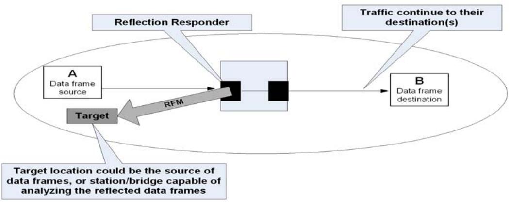
Figure 29-1—Forward path test (FPT)
FPT can be configured on ports where no MPs exist. However, when they are implemented within MPs or configured on ports with MPs, better fault isolation can be achieved. For example, if the target location does not receive the expected reflected data frames in the specified time span, it can send a LBM (21.7) to verify the connectivity between the Target location and the MP on which the RR (29.2.2) is configured. For a network that supports MEPs but not MIPs, FPT can be used to diagnose segment connectivity by configuring an RR on an intermediate node to encapsulate the received CCM in RFM format (29.4.2) and forward them to a target location.
The receiver at the target location records the reflected frames for examination by the operator and may also transfer the reflected frames to an analysis function. Some examples of target location analyzers are as follows: comparing the reflected frames with the original ones to verify if there are any errors, running a proxy application at the target location to simulate the handshakes as if those packets actually reach their original destinations, etc.
As in CFM (Clause 18 through Clause 22), a network operator can only set or activate FPT’s RR within its own maintenance domain. At the customer’s request, a network provider may use DDCFM to verify whether DDFs occur within its domain. FPT’s RR (29.2.2) can only be created or activated by a network provider’s own Network Management System via secure interface. Therefore, customers or other operators cannot set an FPT RR (29.2.2) in a maintenance domain that does not belong to them.
In order for intermediate Bridges and/or a target location to distinguish the reflected data frames from other traffic, each reflected frame is encapsulated with an RFM header. The RFM header added to the reflected data frame carries the same Maintenance Domain level associated with the RR, so that the reflected data frames, each encapsulated with a proper RFM header, are contained within the same Maintenance Domain. The target location has to be in the same maintenance domain to receive the RFMs.
Depending on the conditions specified for selecting data frames to be reflected, some conditions can cause large amount of data frames to be reflected. If there are multiple locations within a network reflecting a large number of data frames simultaneously, excessive traffic could be added to some segments of the network, which may impact network performance. To avoid excessive traffic being added to the network by an RR, this standard recommends only one RR be activated at a time within one maintenance domain.
FPT consists of RR configuration, the action to reflect identified data frames, and the analysis of the reflected data frames. The last step, i.e., analysis of the reflected data frames, is beyond the scope of this standard.
29.1.2.2 Return path test (RPT)
The RPT is to determine whether a flow of data frames can be sent without error from a specific location within a network to a station or stations specified by the destination_address associated with each of the frames under test. The RPT is achieved by an originating station encapsulating each frame of the flow under test with an SFM header, a DR (29.2.6) removing the SFM header, optionally placing its own MAC in the source_address field of the decapsulated data frames, and sending the data frames to a station or stations as specified by the destination_address field. By default, RPT’s DR places its own MAC address in the source_address field of the decapsulated data frames before sending them out. However, a network operator can force a DR not to change the source_address field of the decapsulated data frame before sending it out to conduct special purpose testing.
The RPT allows a network operator to inject specific data frames into the network for testing purposes. To prevent one network operator from injecting traffic to other networks, it is necessary for the associated managed object to be created under secure mode and for SFM originator to be in the same Maintenance Domain as the MP on which DR is defined.
The Figure 29-2 illustrates a simple case of injected traffic from Node B to reach Node A. Multiple data frames can be injected and injected data frames could have different addresses or multicast addresses in their corresponding destination_address field.
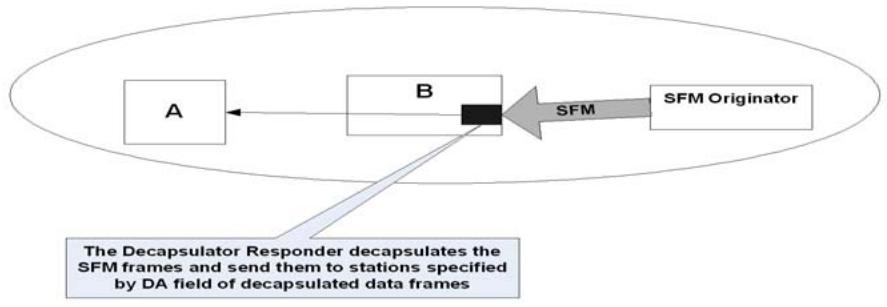
Figure 29-2—Return path test (RPT)
The RPT consists of the DR configuration, the sending of SFMs, the action to decapsulate and forward, and the analysis of the received data frames at their destination(s). The last step, i.e., the analysis of the received data frames at their destination(s), is beyond the scope of this standard.
29.1.2.3 Derived testing scenarios
FPT and RPT can be used together in various ways to achieve more sophisticated testing to diagnose and isolate DDFs. It is beyond the scope of this standard to elaborate different ways of combining FPT and RPT. This subclause only illustrates one example of using both FPT and RPT.
Figure 29-3 shows how to achieve segment fault isolation in the middle of a network using FPT and RPT together. By creating a DR and RR on two Bridge Ports in the middle of a network, a network operator can test whether the specified data frames can traverse through the segment. This type of testing is especially useful to diagnose DDFs out of firewall. This type of testing can also be used to diagnose a connectivity fault between two intermediate Bridge Ports (or two MIPs) by setting the RR filter (29.2.2.1) to the specified CCMs.
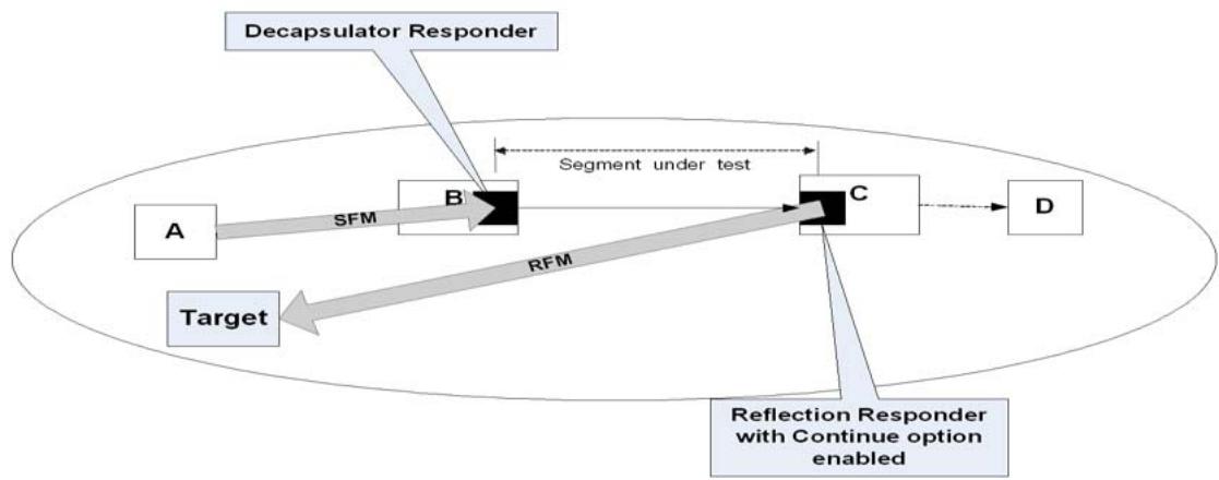
Figure 29-3—Combination of FPT and RPT
29.2 DDCFM Entity operation
This subclause specifies the following:
a) FPT RR
b) FPT RFM Receiver
c) RPT DR
d) RPT frames’ SFM Originator
29.2.1 DDCFM implementation
The DDCFM protocol is performed by the RR, the DR, the RFM Receiver, and the SFM Originator. All of these entities are created and activated by operator commands. The operation of RR, DR, and SFM Originator are timer limited.
Both RFMs and SFMs are CFM PDUs and their format is described in 21.4 and 29.4. They are forwarded in the same way as regular CFM messages. An MEP at higher MD level shall drop the received RFMs and SFMs. An MEP at the same level shall process, but not forward, RFMs and SFMs received from its Active SAP, and shall drop RFMs/SFMs received from its Passive SAP. An MHF shall always forward RFMs/ SFMs received from its SAPs and shall also process those at the same MD level received from its Active SAP.
The RR, RFM Receiver, DR, and SFM originator are CFM entities that are associated with a specific MD, enabling access only to the administrators of this MD. They can be placed at any point in the network that is bounded by any DoSAP of their corresponding MDs. Their relationship to MPs is guided by the MP component entities that the DDCFM entities also require. In particular, the RR does not require any of the MP’s sub-functions (19.2 and 19.3) and correspondingly it is defined as an independent CFM shim. It can be placed at any Bridge Port bounded by the DoSAP of the RR’s associated MD. It does not even require the EISS Multiplex Entity (6.17) or Backbone Service Instance Multiplex Entity (6.18). The same holds true for an SFM Originator. Note that both of them transmit CFM frames that are associated with a specific MA but the creation of these DDCFM entities themselves is not associated with an MA. This in practice means that one RR or SFM Originator can send RFMs or SFMs (respectively), which are associated with different MAs than the encapsulated frames. The other two DDCFM entities have a number of common subentities to the MPs. In particular, on top of their unique (MP) RFM Receiver and (MP) Decapsulator Responder state machines, they require the functions provided by the Type Demultiplexer, Level Demultiplexer, and the OpCode Demultiplexer. In addition if the service is VLAN based, they also require the EISS Multiplex
Entity. All of these make the implementation of the RFM receiver or the DR very simple in the case of an MP where they can reuse the MP component entities and provide the additional functions required by the MP RFM Receiver or MP Decapsulator Responder entities. Implementing these DDCFM entities on non-MPs would require all the previously mentioned MP subentities. Figure 29-5 shows an MP-independent RFM Receiver and Figure 29-6 shows an MP-independent DR. On the other hand, implementing these DDCFM entities on MPs would require only the addition of the MP Decapsulator Responder and MP RFM Receiver component entities in the MP architecture with the appropriate changes in the Opcode Demultiplexer as specified in 19.2 and 19.3.
29.2.2 FPT RR
The RR is a CFM protocol shim for filtering frames to be reflected, copying the filtered frames to the Passive SAP if the Continue option is set, and encapsulating each filtered frame with the RFM header (29.4.2). For an interface supporting DDCFM, an RR shim shall be allowed at EISS/ISS SAPs where MPs are allowed on the protocol stack shown in Figure 22-4, Figure 22-8, Figure 26-2, and Figure 26-8. By placing an RR shim on an aggregated port within a Bridge Port, the RR can reflect data frames from an member link of a LAG to test if specific data frames can go through the link.
The Figure 29-4 illustrates the component entities of an RR.
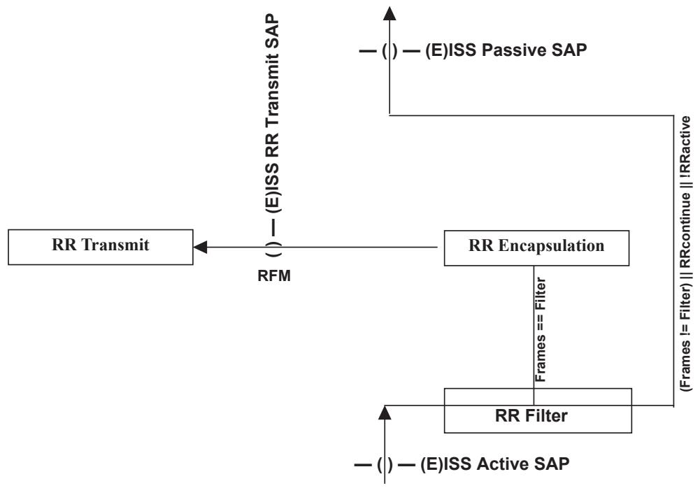
Figure 29-4—Detailed functions of RR
29.2.2.1 RR Filter
The RR Filter function within the RR filters frames from Active SAP that match the Reflection Filtering definition(s) [29.2.3 b2)]. When the RR is active and the sampling interval has expired, a frame that matches the Reflection Filter definition(s) is sent to RR Encapsulation to be reflected. A frame is passed to the Passive SAP when RR is not active, the frame does not match the Reflection Filter definition(s), or the Continue option is true.
To prevent data frames from being reflected multiple times within a network, RFM frames cannot be reflected. An RR Filter definition implicitly includes the condition of the OpCode in common CFM header not equal to RFM, in addition to all other conditions specified.
29.2.2.2 RR Encapsulation
The RR Encapsulation function within the RR is for encapsulating the filtered frame with the appropriate RFM header. If a sampling interval is specified, once a frame meeting the Reflection Filtering definitions is identified within one sampling interval, no more frames shall be encapsulated until the next sampling interval starts.
29.2.2.3 RR Transmit
RR Transmit identifies the egress port by querying FDB and forwards the RFM frames to the LOM entity of the identified egress port. The query uses the Reflection Target address [12.17.2.1.2, b3)] and the vlan_identifier associated with the RFM [29.3.3.3, c)]. If there is no vlan_identifier associated with the RFM, the PVID value of the port where RR is configured is used. If an egress port cannot be identified and the FloodingEnabled flag of the RR is true, then the RFM frame is sent to the LOM entity on every port associated with the VID set of the RFM frame. If the FloodingEnabled flag of the RR is false and an egress port cannot be identified, the RFM frame is dropped.
29.2.3 RR-related parameters
29.2.3.1 RR identification
An RR is identified by the interface upon which the RR is created, a Maintenance Domain that identifies the administrative boundaries, and a value indicating the direction (Up or Down) in which the RR is facing. The interface upon which the RR is created can be a Bridge Port or a member port of a LAG of a Bridge Port.
29.2.3.2 MA for RR
The primary VID associated with RR’s MA is in the RFM emitted by the RR. When MA for an RR is set to 0, then the VID of the filtered frame are used in the corresponding RFM.
29.2.3.3 RR Filter definition
The RR Filter is for selecting data frames to be reflected. Multiple filters can be combined together by “&& (and)”, “|| (or)”, or “! (negation)” operations.
All Bridges supporting DDCFM shall support the following reflection filters (and may support additional Reflection Filters):
a) Reflect All—all frames are selected.
b) VLAN-based selection—all data frames associated with the specified VID are selected.
c) Destination address-based selection—all data frames with the specified destination address are selected.
d) Source address-based selection—all data frames with the specified source address are selected.
e) EtherType.
29.2.3.4 Sampling interval
The sampling interval controls the maximum rate at which frames can be reflected. If no sampling interval is set, then all frames that arrive while the RR is active and match the filter criteria are reflected. If a sampling interval is specified then the first matching frame that arrives during the interval is reflected, other matching frames arriving in that interval are not reflected.
29.2.3.5 Continue option
The Continue option [12.17.2.2.2 b5)] allows the selected data frames to be continued to their original destinations by making a copy of the selected frames to be reflected.
The Continue option is set to be true by default, which means that the selected data frames are branched to two directions—one direction to the RR Encapsulation function, and the other direction to the passive SAP. When the Continue option is set to be false, the selected frames shall only be forwarded to the RR Encapsulation function.
29.2.3.6 Duration for RR to remain active
Reflecting data frames back into network can create extra traffic in the network. To prevent this action running forever, a duration [12.17.2.1.2 b5)] is used to limit the maximum amount of time for the RR to be running. Operator can also specify the maximum number of frames to be reflected. Once activated, RR shall remain active until either its specified duration expires or the maximum number of frames reflected is reached, whichever comes first. An active RR can also be deactivated by operator command before its duration expires.
29.2.3.7 Truncation flag
If the received data frame causes the RFM encapsulated frame to exceed the Maximum Service Data Unit Size (6.5.8), either the data frame is truncated, or the data frame is split into two smaller frames and those two smaller frames are encapsulated by two separate RFM frames. If the Truncation flag is set to be true, the data frame shall be truncated to be encapsulated in one RFM.
29.2.4 Reflection Target and RFM Receiver
The Reflection Target is where the RFM encapsulated reflected frames are forwarded to. The RFM Receiver is a function running on a Reflection Target to pass the received RFMs to their corresponding analyzers.
The Reflection Target has to be within the same Maintenance Domain as the RR in order to receive the RFM encapsulated data frames.
When an RFM Receiver is defined on a Bridge interface that does not support MP, the RFM Receiver is implemented as a separate CFM entity, as depicted in Figure 29-5 for receiving RFMs from Active SAP. It requires a number of the component entities that are required by an MP. If the RFMs are associated with a VID-based MA, the RFM receiver needs to be placed in a demultiplexer SAP provided by an EISS multiplex entity (6.17).
29.2.5 RPT-related parameters
RPT configuration has two parts: one part is to configure SFM Originator and the other part is to configure DR.
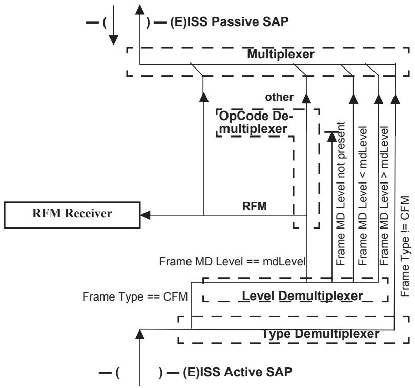
Figure 29-5—RFM Receiver on an non-MP
29.2.6 Decapsulator Responder (DR)
The DR decapsulates SFMs and sends the decapsulated frames toward destinations specified by the destination_address field of the decapsulated data frames. Under normal circumstance, the source_address field of the decapsulated frame is replaced by the DR’s own MAC address to avoid confusing other Bridges’ learning in the network. However, a network operator can enforce the DR not to modify the source_address field of the decapsulated frame for special purpose fault diagnosis. The DR configuration is specified in 12.17.4.1.
DR shim shall be allowed at EISS/ISS SAPs where MPs are allowed on the protocol stack shown in Figure 22-4, Figure 22-8, Figure 26-2, and Figure 26-8.
Multiple DRs can be created on one Bridge interface to receive SFMs at different MD levels or SFMs originated from different SFM Originators.
When an SFM is received by an active DR, it is examined for validity and discarded if invalid. If valid, the received SFM shall be decapsulated. The source_address field of the decapsulated frame is replaced by DR’s own MAC address unless SourceAddressStayFlag is set. The modified frame shall be used to identify the egress port by querying the FDB. The query uses the destination_address and vlan_identifier values of the decapsulated data frame. If the decapsulated frame is untagged, the PVID value of the port where DR is configured is used. The Boolean FloodingEnabled flag of the DR indicates if the frame is to be flooded or discarded if an egress port cannot be identified by FDB. Figure 29-6 illustrates the detailed functions of DR. DR shim can be placed at any places where MPs are allowed on the protocol stack as shown in Figure 22-8.
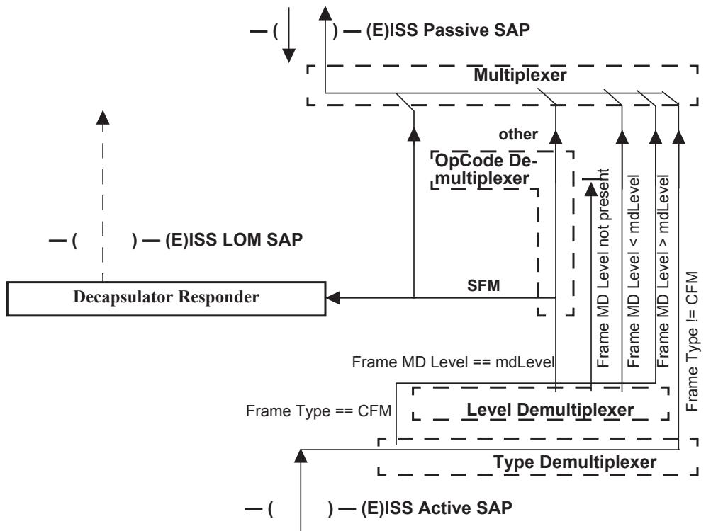
Figure 29-6—Return Path DR
29.2.7 SFM Originator
SFM Originator is for generating SFMs and sending the SFMs to the corresponding DR. Each SFM encapsulates one data frame. The SFM Originator configuration is specified in 12.17.5.1.
The Bridge interface on which SFM Originator is created does not have to support any MP. However, the SFM Originator has to be configured with the same Maintenance Domain level as the DR, so that the SFM can be forwarded to the DR. It is beyond the scope of this standard to address how SFMs are generated.
29.3 DDCFM protocols
This subclause specifies the DDCFM protocols in terms of a number of state machines, the variables and procedures associated with each machine.
29.3.1 RR variables
There is one instance of the following parameters per RR, except the nPendingRFMs variable, that is common to all RRs on the Bridge components (i.e., per Bridge component, but not per RR).
29.3.1.1 RRcontinue
A Boolean variable for the RR’s Continue option [12.17.2.2.2, b5)] attribute.
29.3.1.2 nPendingRFMs
An integer value used to track the number of RFMs to be transmitted. nPendingRFMs is a variable that can be incremented by every RR’s Encapsulation state machine and can be decremented by RR Transmit state machine.
nPendingRFMs is set to 0 when all of the RRs on the Bridge are deactivated.
29.3.1.3 dataReceived
dataReceived is a Boolean variable, which is set to true when there is a data frame received from (E)ISS, and set to false by the RR Filter state machine.
29.3.1.4 dataFrame
This variable is the data frame received from (E)ISS.
29.3.1.5 nFilteredFrameList
This variable keeps track of the number of filtered data frames to be reflected. This variable is incremented by RR Filter and decremented by RR’s Encapsulation state machine.
29.3.1.6 filteredFrameList
This is a list of received data frames from RR Filter that have not been processed yet.
29.3.1.7 nextFilteredFrame
This variable copies the first one on the filteredFrameList to be reflected as RFM. Once a frame is copied to this variable, the frame is removed from the filteredFrameList.
29.3.1.8 RRtime
RRtime is the value of RR Duration (29.2.3.6).
29.3.1.9 RRwhile
RRwhile is a timer variable, which is initialized to RR Duration [12.17.2.2.2, b7)] when RR is activated and used by the RR Filter state machine to time out the active RR. RRwhile has granularity in seconds.
29.3.1.10 RRsampInt
RRsampInt is the sampling interval (29.2.3.4) during which the RR only reflects a maximum of one frame that meets the filter condition. When the sampling interval is not configured, RRsampInt is set to 0.
29.3.1.11 RRsampWhile
A timer variable used by RR Filter state machine to time out sampling interval.
29.3.1.12 RRmaxFrames
The maximum number of frames for RR to reflect after RR is activated [12.17.2.2.2, b8)]. Once activated, RR will stay active until either RRmaxFrames is reached or RRwhile (29.3.1.9) expires, whichever comes first. If RRmaxFrames is set to 0, the RR stays active until RRwhile (29.3.1.9) expires.
29.3.1.13 RRframeCount
A counter used by the RR’s Encapsulation state machine to keep track of the number of data frames to be reflected. Once RRframeCount is equal to or greater than RRmaxFrames, RR is deactivated.
29.3.1.14 filterMatched
A Boolean variable that is set to true if the data frame received matches with the RR’s filter conditions and false if the data frame received does not match the RR’s filter conditions.
29.3.1.15 RRactive
RRactive is true when the corresponding RR is active and false otherwise.
29.3.1.16 nextRFMtransID
The value to place in the RFM Transaction Identifier field of the next RFM to be transmitted. nextRFMtransID is incremented by 1 by the RR’s processRRencap() procedure with each transmission.
This variable is readable as a managed object [12.17.2.3.3, b.14)].
29.3.1.17 maxDataTLVvalueSize
This is the maximum number of bytes allowed to be copied into Reflected Data TLV’s value field in order to keep the RFM’s SDU size not exceeding its Maximum Service Data Unit Size (MSDUS) (6.5.8).
The length of an RFM PDU is 12 octets (4 bytes for CFM header + 1 byte for End TLV(0) + 4 bytes Transaction Identifier + 3 bytes Reflected Data TLV Length/Type field) + the actual number of bytes of the reflected data frame. If there is no other optional TLV for the RFM data frame33, then
a) maxDataTLVvalueSize = MSDUS – (5 (CFM common header length) + 4 (Transaction Identifier) + 3 (Reflected Data Frame TLV Length/Type field))
29.3.1.18 reflectedDataLength
This variable is to hold the value for the Length field of Reflected Data TLV (29.4.2.4).
29.3.2 RR Filter procedures
The following procedures are defined for the RR Filter state machine:
a) filterFrame()
b) forwardFrame()
c) loadFilteredFrameList()
29.3.2.1 forwardFrame()
This procedure passes the frame received to (E)ISS Passive SAP.
29.3.2.2 filterFrame()
filterFrame() is called when RRactive is true and there is a data frame received from EISS. This procedure performs the following steps:
a) If the received data frame from (E)ISS SAP meets the Reflection Filter definition(s), then returns true.
b) Otherwise, returns false.
29.3.2.3 loadFilteredFrameList()
This procedure adds the received frame to the filteredFrameList.
29.3.3 RR Encapsulation procedures
The following procedures are defined for the RR Encapsulation state machine:
a) processRRencap()
b) splitFilteredFrame()
c) constructRFM()
29.3.3.1 processRRencap()
processRRencap() is called when RR is activated and filteredFrameList is not empty. There are two local variables in this procedure: DataFrame_1 and DataFrame_2, which are used when the filtered frame has to be truncated or split into two frames to be reflected.
processRRencap() processes the incoming data frame from the RR Filter as follows:
a) Set the reflectedDataLength variable to the length of the nextFilteredFrame.
b) If the value of reflectedDataLength is larger than the Bridge’s maxDataTLVvalueSize (29.3.1.17), then call splitFilteredFrame (nextFilteredFrame, DataFrame_1, DataFrame_2) and then perform the following two steps:
1) If Truncation flag is set, call constructRFM(TLV_type, maxDataTLVvalueSize, DataFrame_1), where the TLV_type is set to the “Truncated Data TLV” type value defined by Table 21-6
2) If the Truncation flag is not set, perform the following two steps:
constructRFM(TLV_type, maxDataTLVvalueSize, DataFrame_1), where the TLV_type is set to the “Data Part 1 TLV” type value defined by Table 21-6
constructRFM(TLV_type, reflectedDataLength – maxDataTLVvalueSize, DataFrame_2), where the TLV_type is set to the “Data Part 2 TLV” type value defined by Table 21-6
c) Otherwise, call constructRFM(TLV_type, reflectedDataLength, nextFilteredFrame), where TLV_type is set to the “Data TLV” type value defined by Table 21-6.
29.3.3.2 splitFilteredFrame()
This procedure is called when the nextFilteredFrame causes the length of RFM’s SDU size to be larger than the Maximum Service Data Unit Size (6.5.8). There are three parameters for this procedure:
a) nextFilteredFrame, which is an input to the procedure.
DataFrame_1, which contains the first maxDataTLVvalueSize number of bytes from the nextFilteredFrame.
c) DataFrame_2, which contains the remaining bytes from the nextFilteredFrame.
splitFilteredFrame() performs the following steps:
Copy the maxDataTLVvalueSize number of bytes from the nextFilteredFrame to DataFrame_1.
Copy the remaining bytes from the nextFilteredFrame to DataFrame_2.
29.3.3.3 constructRFM()
This procedure is to construct a RFM frame and increment the nPendingRFMs by 1. There are three parameters passed into this procedure:
a) TLV_Type, which could be 3 (i.e., Data TLV) (21.5.6), 9 (Truncated Data TLV) (21.5.1.1), 10 (Data Part 1 TLV), or 11 (Data Part 2 TLV).
b) TLV_Length, which is the length of the reflected data frame.
c) Data frame to be included in the TLV value field.
This procedure constructs the RFM (E)M_UNITDATA.request by the following steps:
d) Set the source_address parameter to the MP’s or Bridge interface’s own MAC address.
e) If the Reflection Target Address [12.17.2.2.2, b4)] is not specified, then source_address of the selected data frame is copied to the RFM’s destination_address parameter; otherwise, Reflection Target Address is copied to the RFM’s destination_address parameter.
f) Set the priority and drop_eligible parameters to the priority and drop_eligible attributes of the Reflection Responder managed object (12.17.2.2.2).
g) In a VLAN aware Bridge, the primary VID associated with the RR’s MA [12.17.2.1.2, b1)] is used as the vlan_identifier. If the RR’s MA is set to 0, the vlan_identifier is determined by the following:
1) If the RR is defined on an S-VLAN component, use the S-VID if the S-VID is present in the selected data frame; otherwise, use the PVID of the port where RR is configured.
2) If the RR is defined on a C-VLAN component, use the C-VID if the C-VID is present in the selected data frame; otherwise, use the PVID of the port where the RR is configured.
h) Copy RFM OpCode to the RFM’s OpCode Field.
i) Copy the RR’s Maintenance Domain Level [12.17.2.1.2, a)] to the RFM’s MDLevel field.
j) Copy the first parameter (TLV_Type) to the Reflected Data TLV Type field.
k) Copy the second parameter (TLV_Length) to the Reflected Data TLV Length field.
l) Copy the third parameter (Data frame) to the Reflected Data TLV value field.
m) Copy the nextRFMtransID to the RFM Transaction Identifier field. Increment nextRFMtransID by 1, wrapping around from 232 – 1 to 0.
n) Increment nPendingRFMs by 1.
o) Set the frame_check_sequence parameter to the unspecified value; sets the connection_identifier to null.
29.3.4 RR Transmit procedure
The following procedure is defined for the RR Transmit state machine:
a) xmitRFM()
29.3.4.1 xmitRFM()
xmitRFM() is called by the RR Transmit state machine. It queries the FDB in order to identify an egress port. The set of potential transmission ports, normally created by the Active Topology enforcement (8.6.1), is the set of all Bridge interfaces that are both in the active set of the vlan_identifier associated with the RFM, and that are in the Forwarding state for that vlan_identifier.
a) Query FDB using the RFM’s destination_address field and vlan_identifier parameter values.
b) If an egress port is identified and the identified Egress port meets the following conditions:
1) The Egress port does not have a Down MEP with higher MD level than the RFM’s MD;
2) The Egress port does not have an Up MEP with same or higher MD level as the received RFM’s MD;
then send an RFM EM_UNITDATA.request to the egress port’s LOM SAP. Otherwise, drop the received RFM frame;
c) If an egress port cannot be identified
1) When the FloodingEnabled flag of the RR [12.17.2.1.2, b7)] is not set, drop the frame.
2) When the FloodingEnabled flag of the RR is set, send M_UNITDATA.request to the LOM’s SAP of every forwarding port that meets the conditions 1) and 2) of item b) above.
29.3.5 RR-related state machines
29.3.5.1 RR Filter state machine
Figure 29-7 depicts the state machine for RR Filter.
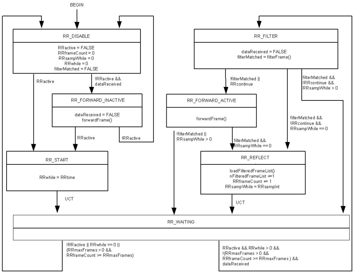
Figure 29-7—RR Filter state machine
29.3.5.2 RR Encapsulation state machine
Figure 29-8 describes the state machine for RR Encapsulation.
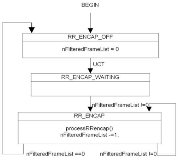
Figure 29-8—RR Encapsulation state machine
29.3.5.3 RR Transmit state machine
RR Transmit state machine (Figure 29-9) can be shared by multiple RRs activated on the Bridge.
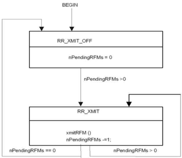
Figure 29-9—RR Transmit state machine
29.3.6 RFM Receiver variables
The following variables are local to the RFM Receiver state machine. There is one instance of these variables per RFM Receiver.
29.3.6.1 RFMreceived
RFMreceived is a Boolean variable, which is set to true by the MP OpCode Demultiplexer when an RFM is received, and cleared by the RFM Receiver state machine.
29.3.6.2 RFMPDU
RFMPDU is a record of the M_UNITDATA.indication or EM_UNITDATA.indication parameters of the last RFM received by the MP OpCode Demultiplexer (19.2.7).
29.3.7 RFM Receiver procedure
The procedure listed in 29.3.7.1 and 29.3.7.2 is defined for the RFM receiver.
29.3.7.1 ReceiveRFM()
ReceiveRFM() procedure performs the following steps:
a) If the destination_address field of the received RFM does not match the RFM Receiver’s MAC address, drops the frame.
b) Otherwise, pass the received RFMPDU to RFM Analyzer.34
Even though RFM Analyzer is out of the scope of this standard, RFM Analyzer has to be able to recognize the value in Reflected Data TLV (29.3.3.2), which could be
— A whole data frame being reflected; or
— A truncated data frame being reflected; or
The first portion of the data frame being reflected; or
The second portion of the data frame being reflected.
If an RFM Receiver is configured on an MP and the RFM Receiver does not receive any RFMs within the expected time frame, it can send a LBM (21.7) to the MP on which the RR is defined to verify the connectivity to the MP. If there is no LBR received, ReceiveRFM() can report an alarm to the network administrator.
29.3.7.2 RFM Receiver state machine
Figure 29-10 describes the state machine for RFM Receivers.
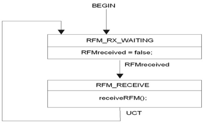
Figure 29-10—RFM Receiver state machine
29.3.8 DR variables
There is one instance of the parameters listed in 29.3.8.1 through 29.3.8.7 per DR.
29.3.8.1 DRwhile
A timer variable used by the Decapsulator Responder state machine to time out the active DR. DRwhile has a granularity finer than or equal to 1 s.
29.3.8.2 DRtime
The time that the DR can remain active after its activation.
29.3.8.3 SFMPDU
SFMPDU is a record of the M_UNITDATA.indication or EM_UNITDATA.indication parameters of the SFM received by the MP OpCode Demultiplexer (19.2.7) when an SFM is received.
29.3.8.4 DRactive
DRactive variable represents the activation status of the corresponding DR. DRactive is set to true when the corresponding DR is activated and set to false when the corresponding DR is deactivated or its duration expires. When DRactive is false, all SFMs received by the Bridge interface are dropped.
29.3.8.5 SFMreceived
SFMreceived is set to true by the OpcodeDemultiplexer (19.2.7) when an SFM is received.
29.3.8.6 previousSFMtransId
previousSFMtransId variable keeps the value of SFM Transaction Identifier of the previously received SFM frame. The previousSFMtransId variable is initialized to zero when the DR is activated.
<!-- merged from 802.1Q_2014_1401-1600.md -->
29.3.8.7 SFMsequenceErrors
SFMsequenceErrors variable keeps the total number of out-of-sequence SFMs received. SFMsequenceErrors is initialized to zero when the DR is activated.
29.3.9 DR procedures
The DR has the following procedures:
a) ProcessSFM()
b) DropSFM()
29.3.9.1 processSFM()
Called by the Decapsulator Responder state machine when an SFM is received and the DR is active. processSFM() processes the incoming SFM in SFMPDU as follows:
a) The SFM is examined for validity using the methods used for CFM as described in (20.46) and discarded if invalid.
b) If the destination_address of the SFM does not match the DR’s own MAC address or the source_address of the SFM does not match with DR’s SFM Originator [12.17.4.3.2 b2)], the frame is discarded.
c) If the SFM frame passes these tests, the frame carried in its Original Data TLV (29.4.3.4) is decapsulated to create an (E)M_UNITDATA.request as follows:
1) The destination_address parameter is set to the destination_address of the frame in the Original Data TLV.
2) If the SourceAddressStayFlag [12.17.4.3.2 b1)] is false, the source_address parameter is set to the DR’s MAC address; otherwise, the source_address parameter is set to the source_address of the frame in the Original Data TLV.
3) The vlan_identifier, priority, drop_eligible, and mac_service_data_unit parameter are set as follows:
If the DR is configured on a port of an S-VLAN component, and the TPID of the frame in the Original Data TLV indicates the S-TAG, the vlan_identifier, priority, and drop_eligible parameters are taken from the corresponding values in the Tag Control Information (TCI) and the mac_service_data_unit is taken from the reminder of the frame following the TCI and excluding the last four octets (FCS).
If the DR is configured on a port of a C-VLAN component, and the TPID in the Original Data TLV indicates a C-TAG, the vlan_identifier, priority, and drop_eligible parameters are taken from the corresponding values in the TCI, and the mac_service_data_unit is taken from the remainder of the frame in the Original Data TLV following the TCI and excluding the last four octets (FCS).
Otherwise, the vlan_identifier is set to the PVID for the port on which the DR is configured, the priority is set to the priority of the SFM, the drop_elibible parameter is set to the value of drop_eligible for the SFM, and and mac_service_data_unit is taken from the frame in the Original Data TLV immediately following the source_address and excluding the last four octets (FCS).
4) Sets the frame_check_sequence parameter to the unspecified value (IEEE Std 802.1AC).
5) Sets the connection_identifier parameter to null.
d) ProcessSFM() queries the FDB using the destination_address and vlan_identifier parameters of the (E)M_UNITDATA.request. The set of potential transmission ports, normally created by the Active Topology enforcement (8.6.1), is the set of all Bridge Ports that are both in the member set of the vlan_identifier and that are in the Forwarding state for that vlan_identifier.
1) If an Egress Port is identified, the decapsulated frame is carried to the related LOM SAP for transmission;
2) If an Egress Port is not identified and the FloodingEnabled flag of the DR is set, the decapsulated frame is flooded to the LOM SAP of all forwarding ports in the VID set; otherwise, the frame is discarded;
e) If the received SFM is not the first frame received by the DR and the value of SFM Transaction Identifier field in the received SFM is not 1 greater than the value saved in the previousSFMtransId, increment SFMsequenceErrors by 1.
f) Set the value of previousSFMtransId to the value of the SFM Transaction Identifier field of the received SFM.
29.3.9.2 DropSFM()
Called by Decapsulator Responder state machine whenever the DR is not active in order to silently discard the received SFM frames.
29.3.10 Decapsulator Responder state machine
Once the DR is configured and activated by network administrator, it remains active until the configured timer expires or being deactivated by the network administrator (see Figure 29-11).
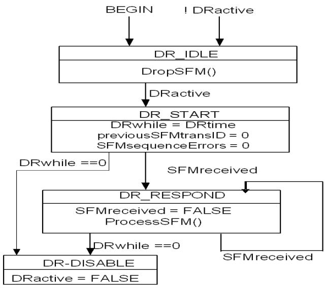
Figure 29-11—Decapsulator Responder state machine
29.4 Encoding of DDCFM PDUs
This subclause specifies the method of encoding DDCFM PDUs. The specifications include the following:
a) The format of RFM
b) The format of SFM
29.4.1 RFM and SFM Header
The RFM Header and SFM Header are same as the Common CFM Header defined by Table 21-3, with extra OpCodes defined for RFM and SFM (Table 21-4).
29.4.2 RFM format
The RFM format is shown in Table 29-1.
Table 29-1—RFM format
<table><tr><td>Field</td><td>Octet</td></tr><tr><td>Common CFM Header</td><td>1–4</td></tr><tr><td>RFM Transaction Identifier</td><td>5–8</td></tr><tr><td>Reserved for definition in future versions of the <eq>protocol^a</eq></td><td></td></tr><tr><td>Reflected Data TLV</td><td>First TLV Offset + 5</td></tr><tr><td>Additional TLV</td><td>First TLV Offset + 5+ Length ofReflected Data TLV</td></tr><tr><td>End TLV (0)</td><td></td></tr></table>
a This field has 0 length in this version 0 of DDCFM. It is shown in order to stress that additional information can be present in future versions of DDCFM, and that a version 0 receiver ignores its contents, if present.
29.4.2.1 Flags
(1 octet) in RFM. The Flags field of the Common CFM Header for RFM is reserved for future use.
29.4.2.2 First TLV Offset
(1 octet) The First TLV Offset field of the Common CFM Header in a RFM is transmitted as 4.
Validation Test: The First TLV Offset field of the Common CFM Header in a RFM contains a value greater than or equal to 4.
29.4.2.3 RFM Transaction Identifier
(4 octets) An RR copies the content of nextRFMtransID variable (29.3.1.16) to this field.
29.4.2.4 Reflected Data TLV
Reflected Data TLV in RFM is a Data TLV (21.5.6) to contain the reflected data frame. The Length field is the total octets of the reflected data frame.
The Type field of the Reflected Data TLV could be one of the following four values (Table 21-6):
a) Data TLV Type value, which is 3
b) Truncated Data TLV Type value, which is 9
c) Data-Part-1 TLV Type value, which is 10
d) Data-Part-2 TLV Type value, which is 11
29.4.2.5 Additional RFM TLVs
The following TLVs may be included in a RFM by each MP originating RFM (RR):
a) Send ID TLV (21.5.3) and
b) Organization-Specific TLVs (21.5.2)
The Additional RFM TLVs may be placed in any order.
29.4.3 SFM format
The SFM format is shown in Table 29-2.
Table 29-2—SFM format
<table><tr><td>Field</td><td>Octet</td></tr><tr><td>Common CFM Header</td><td>1–4</td></tr><tr><td>SFM Transaction Identifier</td><td>5–8</td></tr><tr><td>Reserved for definition in future versions of the <eq>protocol^a</eq></td><td></td></tr><tr><td>Original Data TLV</td><td>First TLV Offset + 5</td></tr><tr><td>Additional TLVs</td><td>First TLV Offset + 5 + Length of Original Data TLV</td></tr><tr><td>End TLV (0)</td><td></td></tr></table>
a This field has 0 length in this version 0 of DDCFM.
29.4.3.1 Flags
(1 octet) in SFM. The Flags field of the Common CFM Header for SFM is reserved for future use.
29.4.3.2 First TLV Offset
(1 octet) The First TLV Offset field of the Common CFM Header in an SFM is transmitted as 4.
Validation Test: The First TLV Offset field of the Common CFM Header in an SFM contains a value greater than or equal to 4.
29.4.3.3 SFM Transaction Identifier
(4 octets) SFM originator may use this field to distinguish the order of SFMs sent. DR may use this identifier to check the order of the received SFMs.
29.4.3.4 SFM Original Data TLV
SFM Original Data TLV is a Data TLV (21.5.6) to contain the original data frame. The Length field is the total octets of the original data frame, including its destination_address, source_address, TPID, TCI, Length/ Type, client data, pad ,and FCS fields.
29.4.3.5 Additional SFM TLVs
The following TLVs may be included in an SFM by each SFM Originator:
a) Send ID TLV (21.5.3)
b) Organization-Specific TLVs (21.5.2)
The Additional SFM TLVs may be placed in any order.
30 Principles of congestion notification
Congestion notification comprises capabilities for detecting and mitigating queue congestion for selected classes of traffic in Virtual Bridged Networks. These capabilities can be used in networks with a bandwidthdelay product on the order of 5 Mbits or less in order to decrease the likelihood of frame loss for Congestion Controlled Flows (CCFs). As the geographical size, per-hop delay, and/or maximum hop count of a network grow, causing the bandwidth-delay product of the network to increase beyond this value, oscillations in buffer occupancy begin, and their amplitude increases gracefully with bandwidth-delay product. If the parameters controlling the algorithm are not adjusted accordingly and the sizes of the Bridges’ buffers are not increased, frames are then likely to be lost due to congestion.
Congestion notification depends on the formation of a cooperating set of systems including VLAN Bridges and end stations to achieve the reduction in frame loss. By partitioning the Bridges’ and end stations’ resources, frames sourced or sunk by noncooperating end stations or Bridges can be carried with minimal contention with CCFs for those resources. Accordingly, congestion notification entities (Clause 31) are specified as shims that make use of and provide the ISS or EISS (IEEE Std 802.1AC, 6.8) at SAPs within the network. The operation of the congestion notification protocol is described in Clause 32, and the formats of the CNM and Congestion Notification TLV are described in Clause 33.
This clause provides the context necessary to understand the congestion notification protocol: how congestion controlled regions of networks are identified; how CCFs are identified and separated from other frames; and how congestion notification entities in Bridges and end stations operate.
This clause introduces the concepts essential to congestion notification as follows:
a) The problem and requirements on the solution are presented (30.1).
b) The basic principles of the Quantized Congestion Notification protocol (QCN) (QCN) are presented, including descriptions of a CP that sends a CNM to a RP (30.2).
c) A CCF consists of frames, all with the same priority value, and all assigned to a single Flow queue and RP in the originating end station (30.3).
d) A Congestion Notification Priority Value (CNPV) is one of the eight priority values that has been configured exclusively for the use of CCFs in the congestion-aware systems of a Virtual Bridged Network (30.4).
e) A CN-TAG can be transmitted with every data frame in a CCF, and is returned in every CNM (30.5).
f) A CND is constructed as a subset of Bridges and end stations in a Virtual Bridged Network, all of which are configured to handle a particular CNPV, the resources of which subset are defended by the Bridges whenever the offered load exceeds the network capacity (30.6).
g) The relationship of Multicast data to congestion notification is explained (30.7).
h) The peering relationship of RPs and CPs in PBNs and PBBNs is explained (30.8).
30.1 Congestion notification design requirements
The congestion notification protocol, congestion notification algorithm (QCN), and supporting protocols specified in this standard meet requirements for the following:
CCF and network performance.
Limiting the implementation complexity, of both RPs and CPs.
Not over-constraining the design of Bridged Networks using CCF.
Facilitating interoperability, coexistence, and deployment into existing networks, and limiting the administrative effort associated with using CCF in a network.
NOTE 1—QCN is designed to operate over a wide range of conditions. This subclause (30.2) necessarily uses qualitative terms such as “low probability,” “small,” “stable,” and “modest” (for brevity). The bibliography (Annex Q) provides references (Alizadeh et al. [B1]) to studies of QCN performance for various network and traffic configurations, using both simulation and a fluid model (see 30.3 for the necessary equations, and for network sizing recommendations).
The following performance requirements are met for s CCFs (30.3):
a) There is a very low probability of frame discard due to buffer overflow at a CP.
b) The average buffer occupancy at each CP that is a Current Congestion Point (CCP) for one or more CCFs is a small fraction of the bandwidth delay product, and largely independent of the number of CCFs, thus ensuring that loss avoidance does not result in large and fluctuating transit delays.
c) The buffer occupancy at a CCP has a low probability of underflow, i.e., of becoming empty and thus failing to use available bandwidth when an RP is rate limiting a CCF as a result of CNMs received from that CCP.
d) When multiple CCFs with a single CCP share that CCP, they obtain very nearly the same share of the bandwidth. When multiple CCFs have one or more CCPs in common they each obtain a share of bandwidth resources proportional to their share of contested resources.
e) The low probability of buffer overflow and underflow at a CCP is maintained for both small and large numbers of CCFs, and when CCFs or the load offered by a given CCF changes.
f) The bandwidth provided to each CP by its attached LAN will be used, at all times, i.e., if the CP’s buffer is not empty it will transmit, given the available bandwidth. The fact that the bandwidth available to one CCF passing through a given CP can be constrained by another CCP will not reduce the bandwidth through that CP for other CCFs not sharing the CCP.
NOTE 2—The probability of frame loss in the absence of CCF naturally depends on the response of higher layer protocols to increasing transit delay, and the importance of avoiding loss on their response. Highly loss sensitive protocols typically lack loss avoidance mechanisms, and no such mechanisms are assumed in the analysis of QCN.
NOTE 3—Requirements a) through d) can be summarized by characterizing the performance of QCN as stable, responsive, and (proportionally) fair with respect to buffer occupancy processes. Requirements e) and f) demand that available resources are used, and that stability not depend on having a large number of slowly changing CCFs.
The following requirements limit the complexity and hence the cost of Bridge Port (CP) support for CCF:
g) The CCF state retained by each Bridge Port is fixed, and determined solely by the number of congestion management transmission queues (i.e., by the number of CPs, one per CNPV, up to a maximum of 7) and the per CP requirements of the congestion notification algorithm (QCN).
h) A CP does not retain any per CCF or per RP state, nor is it required to allocate any data frame passing through the CP to a CCF or an RP. All the information necessary for a CP to address a CNM to an end station, and for that end station to identify the CCF and RP from the CNM, is contained in each frame of a CCF.
i) The buffering required, at each CP, to avoid frame loss should be a small fraction of the network’s bandwidth delay product.
The following requirements limit the complexity and hence the cost of end station (RP) support for CCF:
j) The CCF state retained by each end station for each congestion managed transmission queue, i.e., for each RP, is fixed.
k) The end station state requirements of QCN are determined solely by the number of RPs, and are independent of the number of CCFs and the number of CPs in the network.
l) The number of CCFs, the identification of each CCF, the allocation of transmitted frames to CCFs, and the allocation of CCFs to RPs is determined by each end station independently.
m) The end station is not required to transmit any additional frames, as a consequence either of transmitting or of receiving a frame for a CCF.
n) The CN-TAG for each CCF is independent of changes in RP state information.
o) The CCF protocol and QCN do not use any higher-layer protocol information carried in frames.
p) QCN calculations are simple and can be performed rapidly: i.e., the number of operations required to process each event is fixed, and all multiplications and divisions can be reduced to the use of factors of 2 or the use of a fixed and small lookup table. An RP does not attempt to calculate control loop gains and delays and other, potentially rapidly changing CCF-dependent variables.
NOTE 4—A CP or an RP can retain additional state for the purposes of management, but this state is not required by the CCF protocol or QCN.
NOTE 5—An end station can use higher layer protocol information to decide whether a frame is to be allocated to a CCF, and to select a CCF.
The following requirements ensure that CCF does not over-constrain the design of the network, or limit the use of protocols that determine the active topology of the network:
q) RPs and CPs are unaware of the path taken by frames through the network, require no signaling from the network of changes in path, and take no exceptional action when paths change.
r) An RP does not assume that all frames that it transmits, or any identifiable subset of those frames such as those identified by the end station as belonging to a single CCF or transmitted to the same destination, are constrained to follow the same path through the network. An RP can transmit frames to many different destinations, and transmission to a given destination can be multi-path.
The following requirements support interoperability, facilitate deployment, and limit the administrative effort required to use CCF:
s) The boundaries of each CND are determined automatically.
t) The destination of a CCF can lie outside the transmitting end station’s CND, and the destination end station can be unaware of the use of CCF within the CND. Incremental deployment of CCF is therefore possible.
u) The feedback provided in each CNM provides the receiving RP with the information needed to act on that CNM, and does not require the RP to know or interpret information about the sending CP.
v) PBBNs can be interposed into a CND, in order to reduce the number of MAC addresses leaned by Bridges in environments with large numbers of (perhaps virtual) end stations.
These requirements have a number of additional consequences for the design of QCN, including the following:
w) Additional mechanisms to determine round trip time are not required, as the algorithm is robust over its targeted range of round trip time.
x) QCN cannot regulate frame transmission by acknowledgments, as does Transmission Control Protocol/Internet Protocol (TCP/IP).
30.2 Quantized Congestion Notification protocol (QCN)
This subclause provides an overview of the baseline simulation of the QCN algorithm (Alizadeh et al. [B1]) used to develop this standard. This introduction provides no normative text. It will focus on the key features of the QCN algorithm, omitting the normative details given in the rest of this standard.
The QCN algorithm is composed of the following two parts:
a) CP algorithm: the mechanism by which a congested Bridge or end station buffer samples outgoing frames and generates a feedback message (CNM, 33.3, in this standard) addressed to the source of the sampled frame. The feedback message contains information about the extent of congestion at the CP.
b) RP algorithm: the mechanism by which a Rate Limiter (RL) associated with a source decreases its sending rate based on feedback received from the CP, and increases its rate unilaterally (without further feedback) to recover lost bandwidth and probe for extra available bandwidth.
30.2.1 The CP algorithm
A Bridge containing a CP is modeled as an ideal output-queued Bridge. The CP buffer is shown in $\mathcal { Q } _ { e q } . ^ { 3 5 }$ The CP computes a congestion measure $F _ { b }$ (defined below) and, with a probability depending on the severity of congestion, selects a frame from the incoming stream and sends the value of $F _ { b }$ in a feedback message to the source of the selected frame.
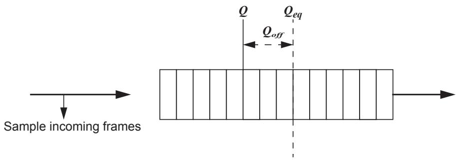
Figure 30-1—Congestion detection in QCN CP
Let Q denote the instantaneous queue size and $\mathcal { Q } _ { o l d }$ denote the queue size when the last feedback message was generated. Let $\mathcal { Q } _ { o f f } { = } Q { - } \mathcal { Q } _ { e q }$ and $Q _ { \delta } = Q - Q _ { o l d } .$
Then $F _ { b }$ is given by Equation (30-1).
$$
F _ {b} = - \left(Q _ {\text { off }} + \mathrm{w} Q _ {\delta}\right) \tag {30-1}
$$
where w is a non-negative constant, taken to be 2 for the baseline simulation. The value of $F _ { b }$ is quantized to 6 bits before transmission, based on $\mathcal { Q } _ { e q }$ and w.
The interpretation is that $F _ { b }$ captures a combination of queue size excess $( Q _ { o f f } )$ and rate excess $( Q _ { \delta } )$ . Indeed, $Q _ { \delta } = Q - Q _ { o l d }$ is the derivative of the queue size and equals input rate less output rate. Thus, when $F _ { b }$ is negative, the buffer is oversubscribed. When $F _ { b } < 0$ , Figure 30-2 shows the probability with which a congestion message is reflected back to the source as a function of $| F _ { b } |$ . The feedback message contains the value of $F _ { b } { \mathrm { : } }$ , quantized to 6 bits. When $F _ { b } \ge 0$ , there is no congestion and no feedback messages are sent.
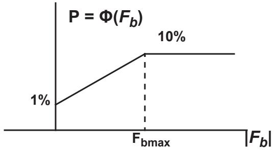
Figure 30-2—Sampling (reflection) probability in QCN CP as a function of $| F _ { b } |$
30.2.2 Basic RP algorithm
The RP is not given positive rate-increase signals by the network. Also, there are no acks at Layer 2 to trigger rate increases, Therefore, the RP requires a local mechanism to determine when, and by how much, the send rate is increased. Before proceeding to explain the RP algorithm, readers need the following terminology:
Current Rate (CR): The transmission rate of the Rate Limiter (RL) at any time.
Target Rate (TR): The sending rate of the RL just before the arrival of the last feedback message, and the new goal for the Current Rate.
Byte Counter: A counter at the RP for counting the number of bytes transmitted by the RL. It triggers rate increases by the RL. See 30.2.2.2.
Timer: A clock at the RP that is also used for triggering rate increases at the RL. The main purpose of the timer is to allow the RL to rapidly increase the rate when its sending rate is very low and bandwidth becomes available. See 30.2.3.
This clause now explains the RP algorithm assuming that only the byte counter is available. Later, how the timer is integrated into the RP algorithm is briefly explained. Figure 30-3 shows the basic RP behavior.
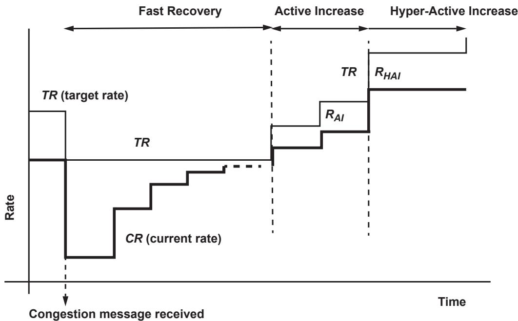
Figure 30-3—QCN RP operation
30.2.2.1 Rate decreases
Rate decreases occur only when a feedback message is received, in which case CR and TR are updated as follows in Equation (30-2) and Equation (30-3):
$$
T R \leftarrow C R \tag {30-2}
$$
$$
C R \leftarrow C R (1 - G _ {d} | F _ {b} |) \tag {30-3}
$$
where the constant $\mathrm { G _ { d } }$ is chosen so that $\mathrm { G _ { d } } | F _ { \mathrm { b m a x } } | = \% ,$ i.e., the sending rate can decrease by at most 50%.
30.2.2.2 Rate increases
Rate increases occur in two phases: Fast Recovery and Active Increase.
Fast Recovery (FR). The byte counter is reset every time a rate decrease is applied and the RP enters the FR state. FR consists of 5 cycles, each cycle equal to 150 KBytes of data transmission by the RL. The RP counts the cycles of the byte counter. At the end of each cycle, TR remains unchanged while CR is updated as follows in Equation (30-4):
$$
C R \leftarrow \frac {1}{2} (C R + T R) \tag {30-4}
$$
The cycle duration of 150 KBytes is chosen to correspond to the transmission of 100 frames, each 1500 bytes long. The idea is that when the RL has transmitted 100 frames and, given that the minimum sampling probability at the CP is 1%, if it has not received a feedback message then it may infer that the CP is uncongested. Therefore, it increases its rate as above, recovering some of the bandwidth it lost at the previous rate decrease episode. Thus, the goal of the RP in FR is to rapidly recover the rate it lost at the last rate decrease episode.36
Active Increase (AI). After 5 cycles of FR have completed, the RP enters the Active Increase (AI) phase where it probes for extra bandwidth on the path. During AI, the byte counter counts out cycles of 50 frames (this can be set to 100 frames for a less frequent probing). At the end of each cycle, the RL updates TR and CR as follows in Equation (30-5) and Equation (30-6):
$$
T R \leftarrow T R + R _ {\mathrm{AI}} \tag {30-5}
$$
$$
C R \leftarrow \frac {1}{2} (C R + T R) \tag {30-6}
$$
where $R _ { \mathrm { A I } }$ is a constant chosen to be 5 Mb/s in the baseline simulation.
30.2.3 RP algorithm with timer
Since rate increases using the Byte Counter occur at a frequency proportional to the current sending rate of the RL, when CR is very small, the duration of Byte Counter cycles when measured in seconds can become unacceptably large. Since the speed of bandwidth recovery (or responsiveness) is a key performance metric, a Timer was included in QCN.
The Timer functions similarly as the Byte Counter: it is reset when a feedback message arrives, enters FR and counts out 5 cycles of T ms duration (T is 10 ms long in the baseline), and then enter AI where each cycle is T/2 ms long.
The Byte Counter and Timer jointly determine rate increases at the RL as shown in Figure 30-4. After a feedback message is received, they each operate independently and execute their respective cycles of FR and AI. Together, they determine the state of the RL and its rate changes as follows:
a) The RL is in FR if both the Byte Counter and the Timer are in FR. In this case, when either the Byte Counter or the Timer completes a cycle, CR is updated according to Equation (30-4).
b) The RL is in AI if only one of the Byte Counter and the Timer is in AI. In this case, when either completes a cycle, TR and CR are updated according Equation (30-5) and Equation (30-6).
c) The RL is in HAI (for Hyper-Active Increase) if both the Byte Counter and the timer are in AI. In this case, the ith time that a cycle for either the Byte Counter or the Timer is completed, TR and CR are updated as shown in Equation (30-7) and Equation (30-8):
$$
T R \leftarrow T R + i R _ {\mathrm{HAI}} \tag {30-7}
$$
$$
C R \leftarrow { {\frac {1}{2}}} (C R + T R) \tag {30-8}
$$
where $\mathrm { R } _ { \mathrm { H A I } }$ is constant set to 50 Mb/s in the baseline simulation (Figure 30-3). So the increments to TR in HAI occur in multiples of 50 Mb/s.
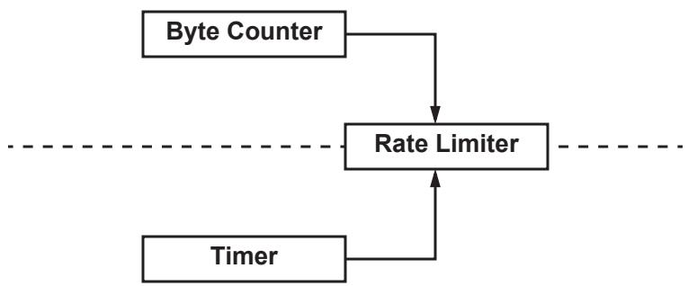
Figure 30-4—Byte Counter and Timer interaction with Rate Limiter
Thus, the Byte Counter and Timer should be viewed as providing the RL opportunities to increase the rate. Their state determines the state of, and hence the amount of rate increase at, the RL.
It is very important to note that the RL goes to HAI only after at least 500 frames have been sent and 50 ms have passed since the last congestion feedback message was received. This doubly ensures that aggressive rate increases occur only after the RL provides the network adequate opportunity (in frames sent for possible sampling) for sending rate decrease signals should there be congestion. This is vital to ensure the stability of the algorithm, and while optimizations can be performed to improve its responsiveness, in the interests of stability and simplicity, the baseline simulation (Alizadeh et al. [B1]) took no further optimization steps.
30.3 Congestion Controlled Flow (CCF)
A CCF consists of all of the frames passing through a single Flow queue (31.2.2.1) in an originating end station. Examples of CCFs include, but are not limited to,
a) The frames carrying data for a single User Datagram Protocol (UDP, IETF RFC 768, STD0006) connection.
b) All of the frames generated by a particular process running in an end station.
c) All of the frames being transmitted by an end station that produce the same value when a hash computation is performed on the source and destination IP addresses, UDP vs. Transmission Control Protocol (TCP) selection, and source and destination UDP/TCP port numbers of the IP packets carried by those frames.
d) All of the frames passing through an RP that have the same destination_address parameter.
e) All of the frames being transmitted by an end station.
f) All of the frames passing through a Bridge Port sharing identical source_address, destination_address, and priority parameters.
g) All of the frames leaving a router that contain IP packets, and have identical values for their source and destination IP addresses, UDP vs. TCP selection, and source and destination UDP/TCP port numbers.
h) All of the frames with a certain value for the priority parameter.
All of the frames in a given CCF are sent with the same priority value, which is a CNPV (30.4).
Not all frames transmitted by an end station with an RP need be CCFs. Frames not belonging to CCFs bypass the Flow queues and RPs.
30.4 Congestion Notification Priority Value (CNPV)
A CNPV consists of one value of the priority parameter such that all of the Bridges’ and end stations’ ports in a Congestion Notification Domain (CND) are configured to assign frames at that value to the same CP and/or an RP. Different CNPVs correspond to classes of applications, or even single applications, such as interprocess communications or disk storage data, that have different requirements for such network resources as latency or bandwidth. Since there are eight values for the priority parameter, a single port in a Virtual Bridged Network can support as many as seven CNPV values; at least one value is required for besteffort traffic.
30.5 Congestion Notification tag (CN-TAG)
An end station may add a CN-TAG to every frame it transmits from a CCF. The CN-TAG contains a Flow Identifier field. The destination_address, Flow ID, and a portion of the frame that triggered the transmission of the CNM are the means provided by this standard by which a station can determine to which RP a CNM applies. How the station makes that determination is beyond the scope of this standard. The reasons for adding a CN-TAG include the following:
a) An end station can identify a particular flow within a CCF that triggered the CNM.
b) It can be simpler for the end station to use a Flow ID, rather than to parse the returned mac_service_data_unit of the original triggering frame, in order to identify either the RP or the particular flow.
c) Depending on the application, e.g., if fragmented IP datagrams are transmitted, it can be impossible to determine either the RP or the particular flow based solely on a returned mac_service_data_unit.
An end station that has only a single RP per CNPV, or that is able to identify the RP on the basis of the returned portion of the triggering frame, can omit transmitting the CN-TAG. The CP always returns a CN-TAG in a CNM with the triggering frame’s Flow ID, or with a 0 Flow ID, if the triggering frame has no CN-TAG. The fixed format for the CNM minimizes the effort required of the CP to generate the CNM.
30.6 Congestion Notification Domain (CND)
In order for congestion notification to successfully control congestion in a Virtual Bridged Network, the managed objects controlling the congestion notification state machines in the Bridges and end stations in that network have to be configured with values that are appropriate to the characteristics of the CCFs generated by the applications that expect congestion controlled services. For example,
a) If frames that were not originated from an RP can enter a CP experiencing congestion, then the CNMs generated by that CP upon receipt of those frames cannot correct the problem, and congestion notification cannot operate correctly.
b) Congestion notification cannot operate correctly if a CP’s configuration is inappropriate for the CCFs passing through it, or if priority values are regenerated in a manner that moves frames in and out of CNPVs.
c) Frames transmitted from an end station with a CN-TAG cannot be understood by an end station that is not congestion aware.
Congestion aware Bridges therefore construct a CND, within which a particular CNPV is supported. A CND is a connected subset of the Bridges and end stations in a Virtual Bridged Network that are appropriately configured to serve a particular CNPV. This standard does not assume that every Bridge in a Virtual Bridged Network will be capable of congestion control, does not assume that every capable Bridge will be so configured, and does not assume that the subset of Bridges in a Virtual Bridged Network forming a CND that serves one CNPV will be the same subset that form a CND serving another CNPV.
CNDs can be created by configuring the Bridges and end stations in a network, or they can be created automatically, using an additional Type Length Value element, the Congestion Notification TLV (D.2.8), that this standard adds to the IEEE 802-2004 Link Layer Discovery Protocol (LLDP). Either way, every Bridge Port knows, for each CNPV, whether its neighbor(s) are or are not all configured with a matching CNPV.
NOTE—If CND boundaries are configured individually, rather than through LLDP, and there is an error in the configuration, there is a risk that frames not originating from RPs will pass through a CP, or that RP-originated frames will pass through a congested Port that has no CP. Either case can result in congestion that cannot be alleviated, with consequent excessive discarding of RP-originated data frames. In addition, such misconfiguration can result in a congestion aware end station being unable to communicate with a congestion unaware end station, because the latter is receiving CN-TAGs that it does not understand.
Making each CND/CNPV independent, rather than making a single determination of neighbor capabilities based on whether all CNPVs are configured the same for all Ports attached to the LAN, allows a CND to be added to or removed from a network already using another CND, without disrupting the operation of the first CND.
30.7 Multicast data
Although control of multicast streams is not an object of this standard, and no simulations or experiments involving multicast data were utilized in the writing of this standard, the transmission of multicast data through a CCF is not prohibited. Some applications primarily send unicast data, but send occasional multicast frames for purposes such as discovery. Transmission of multicast data has been allowed in order to allow well-designed applications using a very small percentage of multicast traffic to operate on a CNPV.
Multicast streams are often sent to multiple destinations along multiple paths through the network, and a unicast stream normally travels along a single path. Therefore, a multicast stream is more likely to encounter any congested ports that exist in a network than is a unicast stream. The consequences of sending multicast streams on a CCF include the following:
a) The RP could limit the CCF to the rate of the slowest (most congested) path taken by the multicast.
The chances of unintended fate sharing are higher in a CCF that included multicast streams. That is, a multicast stream is more likely to unnecessarily slow down a unicast stream sharing the same CCF than one unicast stream is likely to slow down another.
30.8 Congestion notification and additional tags
The transmission of a CNM from a CP to an RP makes the CP and RP peer entities in the sense discussed in IEEE Std 802.1AC. An example of this peering relationship for a VLAN Bridged Network is illustrated in Figure 30-5, with the CP-RP relationship shown by a heavy dashed line.
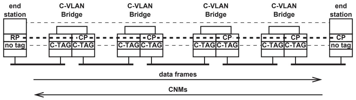
Figure 30-5—CP–RP peering in VLAN Bridged Network
PBBs (Clause 25) could be used in a data center environment, in order to reduce the number of MAC addresses that have to be learned in the core of the network. The I-component (5.7) of a PBB adds and removes I-TAGs (9.7) on data frames. However, as illustrated in Figure 30-6,37 adding an I-TAG to a data frame by an I-component impairs the ability of a CP in the core of that network to return a CNM that will be meaningful to the originating end station. The following two difficulties follow from the fact that a CP in a BCB is not a peer of the RP in an end station:
a) The BCB CP cannot parse the I-TAG and C-TAG, which is necessary in order to find the RP’s MAC address and the data frame’s CN-TAG, in order to build an I-TAG-encapsulated, CNM addressed to the RP.
b) There is no MAC address available to the BCB CP that would be a valid source_address in the CNM when received by the RP.
In order to provide the benefits of PBBNs or other hierarchical bridging technologies to the data center environment, an interworking function (32.16) is defined to allow core CPs to peer with end stations.
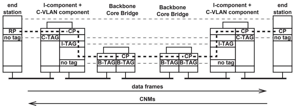
Figure 30-6—CP–RP peering in PBBN
31 Congestion notification entity operation
This clause specifies the following:
a) The architecture of the CP in the Forwarding Process in a congestion aware Bridge component or end station (31.1).
b) The architecture of a CP and an RP in a congestion aware end station (31.2).
NOTE—Clause 30 introduces the principles of congestion notification operation and the network architectural concepts that support it. Clause 32 specifies the protocols operated by entities defined in this clause. Clause 33 specifies the encoding of the PDUs used by congestion notification.
The models of operation in this clause provide a basis for specifying the externally observable behavior of congestion notification, and are not intended to place additional constraints on implementations; these can adopt any internal model of operation compatible with the externally observable behavior specified. Conformance of equipment to this standard is purely in respect of observable protocol.
31.1 Congestion aware Bridge Forwarding Process
Figure 8-11 illustrates the details of the Bridge Forwarding Process. Figure 22-1 shows a different view of those details, rearranged so that those entities of the Forwarding Process that are concerned only with a single Bridge Port can be put in the proper relationship to entities such as CFM shims. Figure 31-1 shows only the queuing functions of Figure 22-1, as modified for a congestion aware Bridge. Two new entities are added for the congestion aware Bridge: the CP (31.1.1) and the CP ingress multiplexer (31.1.2).
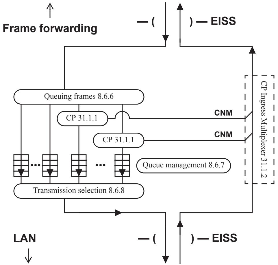
Figure 31-1—CPs and congestion aware queues in a Bridge
31.1.1 Congestion Point (CP)
As described in 32.8 and 32.9, based on the state of its internal variables, and a frame given the CP by the Queuing frames entity (8.6.6) in an EM_UNITDATA.request (parameters) (32.9.3), a CP either inserts the frame into its attached queue or discards the frame, and can generate a CNM, based on the frame. Discarded frames are counted in the variable cpDiscardedFrames (32.8.12). Frames successfully queued are counted in the variable cpTransmittedFrames (32.8.13). Any CNM generated is passed to the CP ingress multiplexer (31.1.2, Figure 31-1) or Flow multiplexer (31.2.4, Figure 31-2) for transmission back to the RP that sourced the frame.
Congestion notification does not operate correctly if frames not belonging to a CCF are allowed to pass through a CP. The CND operations (32.1) help to ensure that the only frames passing through a CP belong to CCFs.
The CP shall remove the CN-TAG from every frame passing through it with a priority value (a CNPV) for which the port on which the CP resides is acting in cptEdge or cptInterior CND defense mode.
The functions of Figure 22-1 could be implemented in different ways than that illustrated, without altering the externally observed behavior of the conformant equipment. For example, the CP could pass a copy of the output frame triggering a CNM to a function in the higher layer interfaces of a Bridge, which in turn, could generate the CNM. However, in order to provide a management interface that is useful over a wide range of implementations, the following provisions are made:
a) CNMs generated on a Bridge Port are not counted in the Frames Received (12.6.1.1.3:a) or Octets Received (12.6.1.1.3:b) counters.
b) CNMs generated on one Bridge Port are counted, as are ordinary data frames, on the Bridge Ports (if any) on which they are output.
If a Bridge supports the dot1agCfmVlanTable or the ieee8021CfmVlanTable, its CPs transmit each CNM to the Primary VID associated with the vlan_identifier of the frame triggering the CNM’s transmission.
31.1.2 CP ingress multiplexer
Inserts the CNMs generated by the CPs (31.1.1) among the frames received from the LAN.
31.2 Congestion aware end station functions
Figure 31-2 illustrates the architecture of the queue functions of a congestion aware end station. These functions offer a service to higher layers through a single instance of the ISS or EISS, and utilize an instance of the ISS or EISS to connect to the lower layers. The Output flow segregation function is presumed to exercise control over the higher layers’ ability to present frames for transmission through the ISS or the EISS, and the Reception selection function to control the flow of frames to the higher layers, by means of additional parameters local to this instance of the ISS or the EISS and/or locally significant LMI parameters (IEEE Std 802.1AC), neither of which are specified by this standard.
In Figure 31-2, the outbound queue block, in the lower left of Figure 31-2, is exactly the same as the output queues in a Bridge Port that is not congestion aware, as illustrated in Figure 22-1.
The remaining entities illustrated in Figure 31-2 are those that are peculiar to a congestion aware end station, and are further described in the following subclauses.
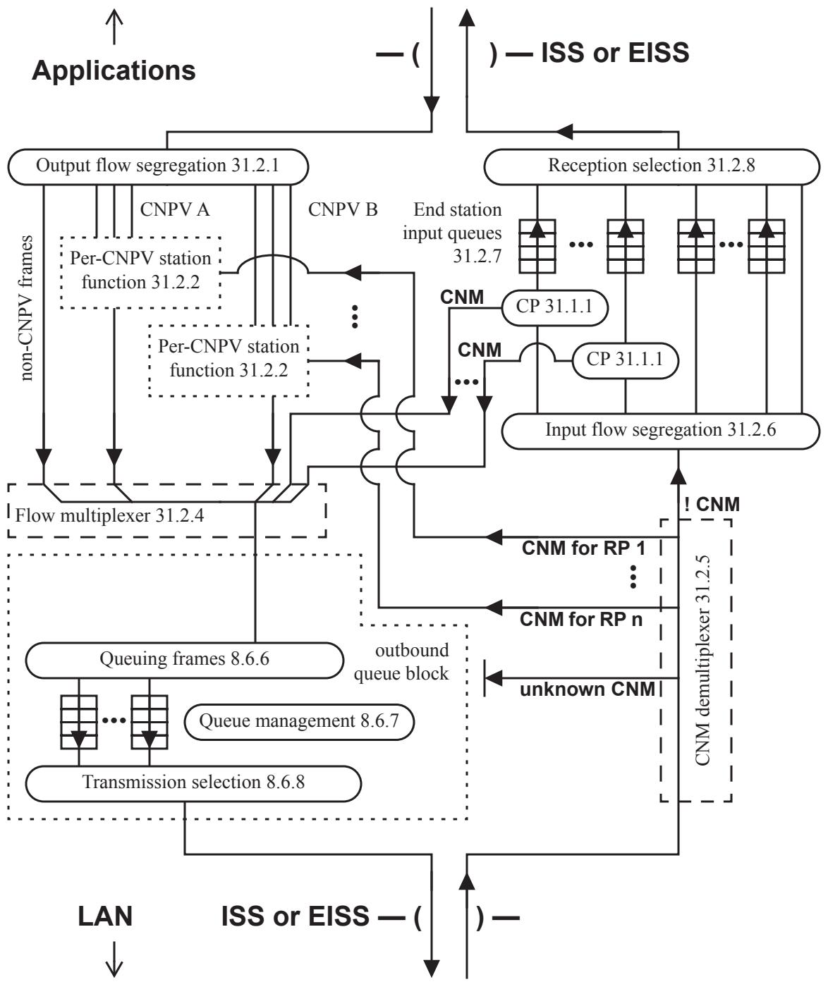
Figure 31-2—Congestion aware queue functions in an end station
31.2.1 Output flow segregation
For each frame received from the upper layers for transmission, the Output flow segregation entity
a) Assigns the frame a priority parameter based on the priority presented from the upper layer and/or upon other criteria, unspecified by this standard.
b) Determines, using priority value and the Flow Select Database (31.2.3), to which Flow queue, if any, the frame is to be assigned.
c) If the frame is not assigned to any Flow queue (the frame’s priority is not a CNPV), passes the frame directly to the Flow multiplexer entity (31.2.4).
d) If the frame is assigned to a particular Flow queue (the frame’s priority is a CNPV), enqueues the frame in the selected Flow queue.
e) For frames that are assigned to a Flow queue, depending on the state of the Flow queue to which the frame is assigned, and through means unspecified by this standard, can influence the higher layers’ presentation of further frames to the Output flow segregation entity.
The Output flow segregation entity never discards a frame. Every frame presented to it is either passed to the Flow multiplexer entity (31.2.4) or stored in a Flow queue, as described previously. This standard assumes that the Output flow segregation entity can apply means, unspecified by this standard, to prevent the upper layers from offering a frame that should be stored in a Flow queue, but for which the Flow queue has insufficient resources.
The default configuration for an end station shall have a single Flow queue per CNPV. An end station may support additional Flow queues, or support more than one CNPV with a single Flow queue.
NOTE—Requirements for a default configurations do not imply that explicit action via SNMP is required to change from the default. For example, managed objects in an end station can be adjusted by an application program.
If the Output flow segregation function in an end station can change its method for assigning frames to Flow queues, it shall not do so in a manner that impairs the ability of any compliant CP implementation to throttle the data from the sourcing end station, and shall not materially increase the likelihood of misordered frame transmissions in a manner that adversely impacts the higher layers’ functions.
31.2.2 Per-CNPV station function
There is one Per-CNPV station function on each Port of a congestion aware end station for each priority value that is a CNPV. All of the frames passing through a Per-CNPV station function have the same CNPV priority parameter value.
As illustrated in Figure 31-3, each Per-CNPV station function is composed of the following entities:
a) One or more Flow queues (31.2.2.1).
b) One or more RPs (31.2.2.2), each associated with exactly one Flow queue, each comprising
1) A RP state machine (31.2.2.3) for each RP.
2) A Rate Limiter (31.2.2.4) for each RP.
c) One Flow Selection function (31.2.2.5).
31.2.2.1 Flow queue
A Flow queue is a first-in-first-out queue of frames, all for the same CNPV. An Output flow segregation entity selects the Flow queue into which a given frame is inserted, and an RP determines when a frame is removed from a Flow queue.
NOTE—The Flow queue is a notional convention used to unambiguously describe the behavior of the RP. An end station can implement the Flow queue without explicitly storing frames in a queue, based on its knowledge of the state of the higher-layer applications supplying the frames.
31.2.2.2 Reaction Point (RP)
A single RP is associated with each Flow queue. An RP is composed of a RP state machine (31.2.2.3) and a Rate Limiter (31.2.2.4).
From Output flow segregation 31.2.1
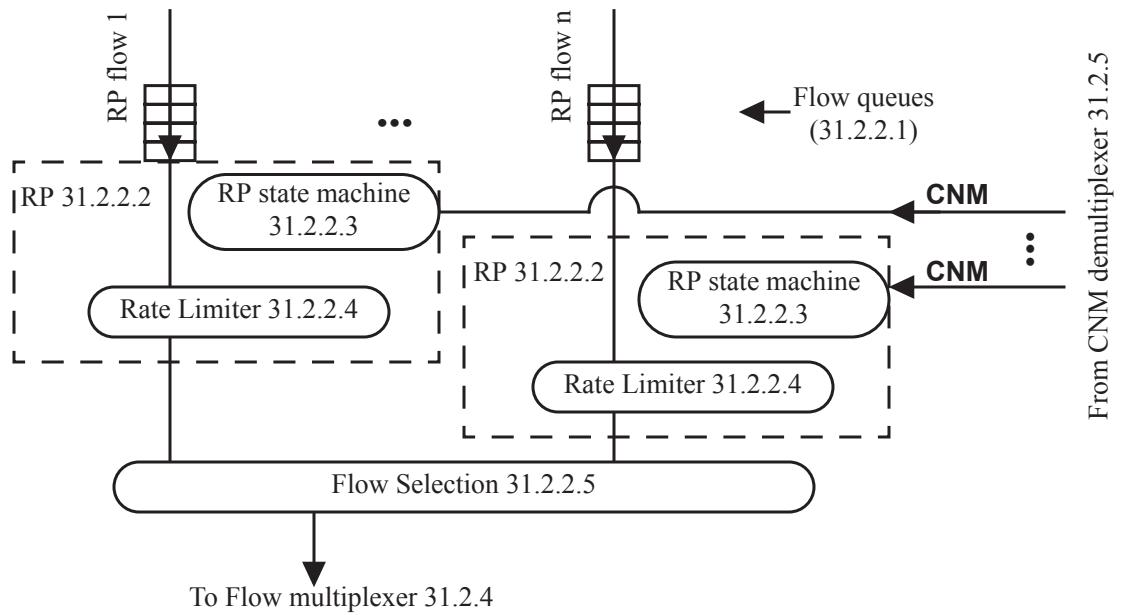
Figure 31-3—Per-CNPV station function
31.2.2.3 RP state machine
A single RP state machine is associated with each Flow queue. As described in detail in Clause 32, the RP state machine consists of a timer (32.12), variables (32.10, 32.11, and 32.13), procedures (32.14), and a state machine (32.15) that determine the value of the rpLimiterRate variable (32.13.8), which, via the Rate Limiter (31.2.2.4), controls the transmission of frames from the Flow queue. The state machine and variables, in turn, are controlled by the frames input, managed objects (12.21), the Output flow segregation entity (31.2.1), and the CNMs received from the CNM demultiplexer (31.2.5).
31.2.2.4 Rate Limiter
A single Rate Limiter is associated with each Flow queue. The Rate Limiter enforces the output rate, rpLimiterRate (32.13.8), determined by the RP state machine (31.2.2.3). The octets in the frames passed from the Rate Limiter to the Flow Selection function (31.2.2.5) are counted in rpByteCount (32.13.2). The details of the operation of the Rate Limiter are not specified by this standard, but the measurable output rate is specified.
For a given measurement period T, $R _ { T }$ is defined as the integral of rpLimiterRate over T, and $L _ { T }$ as the number of octets actually output to the LAN, including preambles, inter-frame gaps, etc., stemming from frames that pass through that RP’s Rate Limiter. An end station shall ensure that
$$
L _ {\mathrm{T}} \leq (1. 0 5 \times R _ {\mathrm{T}}) + (1 6 \text { maximum - sized frames }) \tag {31-1}
$$
for the two values of T = one second and T = 1 million bits divided by the physical line rate (in bits per second), where any number of simultaneous measurements can start at any time.
NOTE 1—The rate computations and variables [Equation ((31-1)), 32.13.6, 32.11.6, etc.] include all of the octets associated with a frame on the LAN, including preambles, inter-frame gaps, etc., and thus reflect actual physical data rates. However, the resource actually protected by congestion notification is octets in buffers, not octet times on wires. Per-frame overhead on the LAN is added to serve as a reasonable approximation, made at the RP, to the actual size of the frame in the Bridges’ or end stations’ buffers. The extra 5% margin in Equation ((31-1)) is provided because this approximation is inexact.
NOTE 2—Although the simulations have been studied with a burst of one maximum-sized frame, this standard allows the end stations to send data in bursts of 16 maximum-sized frames, primarily to ease implementations. Larger bursts of data have a negative impact on the overall performance of the QCN algorithm, and can lead to lower link utilization.
31.2.2.5 Flow Selection
The Flow Selection function decides from which Flow queue in its Per-CNPV station function, if any, a frame will be offered to the Flow multiplexer. Whenever the output queue that receives frames from the Flow Selection function (via the Flow multiplexer) is full, the Flow Selection function shall not present any frame to the Flow multiplexer; this ensures that no frames in CNPVs will be discarded in the Port due to a lack of room in the output queue.
By means unspecified in this standard, the Flow Selection function selects frames to pass to the Flow multiplexer from the uncontrolled Flow queues (31.2.2.1) and Rate Limiters (31.2.2.4). Whenever a frame is passed from a Rate Limiter through the Flow Selection function to the Flow multiplexer, the Flow Selection function calls TransmitDataFrame (32.14.3) to update the RP variables (32.13). If the port’s neighbor is ready to receive frames with CN-TAGs for the frame’s CND (defense mode is cptInteriorReady), the Flow Selection function may insert a CN-TAG (30.5) at the beginning of the frame’s mac_service_data_unit, and if not (any CND defense mode other than cptInteriorReady), it shall not insert a CN-TAG. (See 33.2 for a further explanation of CN-TAG insertion.)
31.2.3 Flow Select Database
The Flow Select Database is used by the Output flow segregation (31.2.1) entity to determine to which Flow queue (31.2.2.1) a given frame is assigned.
The means by which the Flow Select Database selects a Flow queue is unspecified by this standard.
31.2.4 Flow multiplexer
The Flow multiplexer merges the frames from the Per-CNPV station functions’ Flow Selection functions (31.2.2.5), the frames bypassing the Per-CNPV station functions, and the CNM frames from the CPs (31.1.1), and delivers the frames to the Queuing frames (8.6.6) entity in the end station’s output path.
31.2.5 CNM demultiplexer
The CNM demultiplexer identifies CNMs received from the LAN, uses the Flow ID (33.2.1) and/or Encapsulated priority (33.4.7) to determine to which RP (31.2.2.2) each CNM is intended, and directs them to the correct RPs. This standard does not specify whether or how the end station can use the Flow ID to further identify one or more individual flows within a Flow queue and its associated RP. If a CNM is received that has no CN-TAG, or a CN-TAG whose Flow ID is unknown to the RP, the CNM is discarded. All non-CNM frames are passed to the Input flow segregation entity (31.2.6).
31.2.6 Input flow segregation
For each frame received from the lower layers for reception, the Input flow segregation entity:
a) If the frame’s priority is not a CNPV, decides, in an unspecified manner, whether to pass the frame to an unspecified queue, pass it to the higher layers, or discard it.
b) If the frame’s priority is a CNPV, passes the frame to a CP (31.1.1), selected by unspecified means, for processing.
NOTE 1—For example, an end station might support a single CP, or support one CP per CNPV, per VID, per application, or per data flow. Neither these nor any choices for CP selection are required by this standard.
The Input flow segregation entity never discards a CNPV frame. Every CNPV frame presented to it is passed to a CP, as described previously.
NOTE 2—This does not mean that a station cannot drop CNPV frames. See 31.2.7.
31.2.7 End station input queue
The number and operation of end station input queues and the method used to drain these queues (i.e., to select and transfer frames to the receiving higher layer applications) are not specified by this standard. However, the procedures performed by a CP (32.9) require that its associated end station input queue exist, and possess certain operational parameters (32.8).
In the unfortunate event that a misconfiguration or an unfortunate sequence of frame transmissions results in more CNM frames arriving at a station than it can process, an end station input queue can fill up, and discard a frame presented to it by its CP or by the Input flow segregation (31.2.6) entity.
31.2.8 Reception selection
The Reception selection entity selects frames for delivery to the upper layers. It takes the place of the Transmission selection entity (8.6.8) of a congestion aware Bridge. The selection algorithm depends on interactions between the applications receiving the data, the operating system supporting those applications, and the received frames that are not specified by this standard. The Reception selection entity is shown in Figure 31-2 for completeness, to indicate that frames enqueued by the Queuing frames entity (8.6.6) are, in fact, removed from the queues.
If the first octets of the mac_service_data_unit of a frame selected by the Reception selection entity are a CN-TAG, Reception selection removes the CN-TAG from the mac_service_data_unit before passing the frame to the higher layers. (See 33.2 for a further explanation of CN-TAG removal.)
32 Congestion notification protocol
Congestion-aware systems can participate in the congestion notification protocols specified in this clause, namely:
a) CND operations (32.1).
b) The variables controlling congestion notification at the end station or Bridge component (32.2) and Port and CNPV levels (32.3),
c) The variables (32.4), procedures (32.5), and state machine (32.6) that control the defense of a CND.
d) The congestion notification protocol (32.7).
e) The variables (32.8) and procedures (32.9) that define a CP.
f) The variables associated with all (32.10), or a subset of (32.11), the RPs on a given Port and CNPV.
g) The timer (32.12), variables (32.13), procedures (32.14), and state machine (32.15) that define the operation of a single a RP.
h) The processing of CNMs by a congestion notification and encapsulation interworking function (32.16).
NOTE—Clause 30 introduces the principles of congestion notification operation and the network architectural concepts that support it. Clause 31 breaks down the congestion notification entities into their components. Clause 33 specifies the encoding of the PDUs used by congestion notification.
32.1 CND operations
As described in 30.6, a CND is a connected subset of a Virtual Bridged Network configured to support a particular CNPV. This standard provides a means whereby a VLAN Bridge or end station can recognize the like-configured ports of a CND (32.1.1), and defend its CND against incoming frames from outside the CND.
32.1.1 CND defense
Unless every Bridge along a path between two congestion aware end stations using a particular CNPV is configured for congestion notification (belongs to a CND), and unless the Bridges ensure that frames not in CNPVs use different queues than the queues used by those two end stations, those end stations will not accrue the advantages that congestion notification offers. Therefore, steps must be taken at the boundaries of a CND to protect both the CND and the network outside the CND.
Every frame received on a Port passes through the ISS Support by specific MAC procedures (IEEE Std 802.1AC), which can change the priority parameter of the received frame, using the Port’s Priority regeneration table, Table 6-4. This table can be controlled by a managed object (12.6). In addition, in order to prevent frames not in CNPVs from entering CP-controlled queues, each Port’s Priority regeneration table can be modified.
If a Port’s neighbor is known to also be configured for a particular CNPV, the entry in the Port’s Priority regeneration table for that CNPV is ignored, and the priority is never changed on input. The Bridge component or end station connected to that Port can be trusted to use that CNPV. If the Port’s neighbor is known to not be configured for a particular CNPV, the entry in the Port’s Priority regeneration table for that CNPV shall be overridden to translate the CNPV to an alternate non-CNPV value. The neighboring system is not trusted, so the priority values of any frames carrying the CNPV’s value are changed. Altering the priority values of received frames defends the CND from frames not originating from an RP. Similarly, if a CNPV is configured on any Port, then on that Port, the Port’s Priority regeneration table shall be overridden to prevent any other priority value from being remapped into that CNPV.
If a port has multiple neighbors, or if the neighbor on a Port is not congestion aware, then the CN-TAGs shall be removed from any frames transmitted on a CNPV. This ensures that the benefits of congestion notification can be provided as far as possible along a path from a congestion aware source to a noncongestion aware destination. Furthermore, CN-TAGs shall be removed from any frames transmitted from a CNPV toward a system that is congestion aware, but is still remapping the CNPV to a non-CNPV priority.
Thus, for each priority value, the CND defense mode can take one of the following four values, whether derived from LLDP or set by managed variables:
cptDisabled: The congestion notification capability is administratively disabled for this priority value and port. This priority is not a CNPV. The priority regeneration table (6.9.4) controls the remapping of input frames on this port to or from this priority. CN-TAGs are neither added by an end station nor stripped by a Bridge.
cptEdge: On this port and for this CNPV, the priority parameters of input frames are remapped to an alternate (non-CNPV) value, and no priority value is remapped to this CNPV, regardless of the priority regeneration table. CN-TAGs are not added by an end station and are removed from frames before being output by a Bridge.
NOTE—The cptEdge CND defense mode is optional for an end station. See 32.4.9.
cptInterior: On this port and for this CNPV, the priority parameters of input frames are not remapped to another value, and no priority value is remapped to this CNPV, regardless of the priority regeneration table. CN-TAGs are not added by an end station, and are removed from frames before being output by a Bridge.
cptInteriorReady: On this port and for this CNPV, the priority parameters of input frames are not remapped to another value, and no priority value is remapped to this CNPV, regardless of the priority regeneration table. CN-TAGs can be added by an end station and are not removed from frames by a Bridge.
The determination of the operational state of a CNPV on a given port is determined by variables and by LLDP (32.1.1, 32.2.1, 32.3.7, 32.3.4, 32.4.1, 32.4.3).
Taken together, these capabilities ensure that as long as the default values of the managed variables controlling CND defense are not overridden with incorrect values:
a) A data frame received by an end station on a CNPV has been governed by congestion notification along its entire path from the transmitting end station.
b) Uncontrolled data streams sourced by an end station that is congestion unaware cannot pass through a CP, with a resultant excessive loss of congestion aware frames.
c) A data frame carrying a CN-TAG cannot be delivered to a system that is congestion unaware, and thus be unreadable by that system.
It is therefore recommended that the network administrator allow CND recognition to operate automatically (32.1.2).
CND defense operates on each LAN separately; it does not ensure the existence of an end-to-end congestion aware path from end station to end station through a VLAN Bridged Network. Misconfiguration, the presence along the path of a congestion unaware Bridge, or the activation of a new Bridge or LAN (temporarily) can cause frames to exit a CND, and hence the following to occur:
d) Data frames can be transmitted by a congestion aware end station on a CNPV, then be uncontrolled for congestion along some part of their path, and be delivered to an end station on a non-CNPV priority value with no CN-TAG.
e) If a congestion aware end station transmits data frames with CN-TAGs, and is connected to a congestion unaware end station along a path consisting entirely of congestion unaware or
misconfigured Bridges, the receiving end station will be unable to understand the CN-TAG, and thus unable to process the data frames.
f) If a system generates CNMs on a CNPV (not recommended, see 32.2.2), they can be delivered on a non-CNPV priority value with no CN-TAG.
32.1.2 Automatic CND recognition
Congestion notification can use the Link Layer Discovery Protocol (LLDP), defined in IEEE Std 802.1AB, to advertise the CNPVs supported on a Bridge’s or end station’s port, to determine whether the other Bridges’ or end stations’ ports connected to the same LAN are configured for those same CNPVs, and to control the operation of the CND defenses (32.1.1).
Multiple instances of LLDP can be run on a single port. Each instance’s LLDPDUs use a different destination_address and therefore can reach different distances through a Virtual Bridged Network, depending on the types of the devices in that network and their connectivity. Since any Bridge that is not congestion aware can spoil the ability of the Virtual Bridged Network to minimize frame loss, the selection of which LLDP instance is used for CND defense defaults to the Nearest Bridge Address (01-80-C2-00-00- 0E). This instance minimizes the reach of LLDP, and hence the risk that a noncongestion aware Bridge is present.
As described in D.2.8, a single Congestion Notification TLV can be inserted into the LLDPDUs transmitted from any Bridge or end station port that is configured to support a CNPV. The Congestion Notification TLV carries two fields that together provide for automatic control the of the CND defenses:
a) Eight per-priority CNPV indicators (D.2.8.3), one per priority level, indicating whether each priority is or is not a CNPV on this port; and
b) Eight per-priority Ready indicators (D.2.8.4), one per priority level, indicating whether the priority remap defenses are disabled on this port.
For every CNPV configured on a port, if LLDP finds exactly one remote neighbor, and if that neighbor’s database in the port’s LLDP table carries a Congestion Notification TLV (D.2.8) with that CNPV’s bit set in the per-priority CNPV indicators, then that CNPV is known to be configured on the remote system’s port. This condition is summarized by the cnpdRcvdCnpv variable (32.4.11). Similarly, the cnpdRcvdReady variable (32.4.11) indicates whether the remote neighbor has or has not turned off its priority remapping defense. The read-only managed object cnpdAutoDefenseMode (32.4.3) indicates the results of the LLDP.
32.1.3 Variables controlling CND defense
In order to control CND defense, CN component managed objects (12.21.1), CN component priority managed objects (12.21.2), CN Port priority managed objects (12.21.3), and Congestion Point managed objects (12.21.4) override and are overridden by each other as follows:
a) Altering the CN component managed object (12.21.1) or CN component priority managed object (12.21.2) does not alter the values of any of the other managed objects (12.21.3, 12.21.4, 12.21.6).
b) If cngMasterEnable (32.2.1) is FALSE, all congestion notification activity is suppressed; the Priority Regeneration Table (6.9.4) operates normally, and CNMs, CN-TAGs, and LLDP Congestion Notification TLVs are never generated and are always ignored on receipt. If TRUE, the other managed objects control the operation of congestion notification.
c) The Port/priority and component objects override each other as shown in Table 32-1 and Table 32-2. In each case, if the Port/priority object contains the specified value, the component or component/ priority object controls the specified function.
Table 32-1—LLDP instance selection managed object overrides
<table><tr><td>(Per-port per-priority)cnpdLldpInstanceChoice32.4.4</td><td>(Component per-priority)cncpLldpInstanceChoice32.3.6</td><td>CongestionNotification TLVis sent/received</td><td>LLDP instance isselected by</td></tr><tr><td>cnlNone</td><td>any</td><td>No</td><td>None selected</td></tr><tr><td>cnlAdmin</td><td>any</td><td>Yes</td><td>(Per-port per-priority)cnpdLldpInstanceSelector32.4.5</td></tr><tr><td>cnlComponent</td><td>cnlNone</td><td>No</td><td>None selected</td></tr><tr><td>cnlComponent</td><td>cnlAdmin</td><td>Yes</td><td>(Component per-priority)cncpLldpInstanceSelector32.3.7</td></tr></table>
Table 32-2—CND defense mode selection managed object overrides
<table><tr><td>(Per-port per-priority)cnpdDefModeChoice32.4.1</td><td>(Component per-priority)cnpdDefModeChoice32.3.1</td><td>CND defense mode is selected by</td><td>Alternate priority is selected by</td></tr><tr><td>cpcAdmin</td><td>any</td><td>(Per-port per-priority)cnpdAdminDefenseMode32.4.2</td><td>(Per-port per-priority)cnpdAlternatePriority32.4.6</td></tr><tr><td>cpcAuto</td><td>any</td><td>(Per-port per-priority)cnpdAutoDefenseMode32.4.3</td><td>(Component per-priority)cncpAutoAltPri32.3.3</td></tr><tr><td>cpcComp</td><td>cpcAdmin</td><td>(Component per-priority)cncpAdminDefenseMode32.3.4</td><td>(Component per-priority)cncpAlternatePriority32.3.2</td></tr><tr><td>cpcComp</td><td>cpcAuto</td><td>(Per-port per-priority)cnpdAutoDefenseMode32.4.3</td><td>(Component per-priority)cncpAutoAltPri32.3.3</td></tr></table>
32.2 CN component variables
Every congestion aware end station or Bridge component has a set of CN component variables to control the overall operation of congestion notification. All of these variables are included in the CN component managed object (12.21.1). Variables in this section marked, “CP only” are not required for an end station that does not support CPs. The CN component variables include the following:
a) cngMasterEnable (32.2.1)
b) cngCnmTransmitPriority (32.2.2)
c) cngDiscardedFrames (32.2.3)
d) cngErroredPortList (32.2.4)
32.2.1 cngMasterEnable
A Boolean value specifying whether congestion notification is enabled in this Bridge component or end station.
32.2.2 cngCnmTransmitPriority
(CP only) The priority value to be used when transmitting CNMs from this Bridge component or end station (default 6) (32.9.4:h).
NOTE—If cngCnmTransmitPriority is itself a CNPV, then it is possible that another CP could generate a CNM in response to a CNM sent by this Port. Although this is not desirable, the fact that CNMs are sent in response to only a sampling of frames means that the network will not fail due to an excessive number of CNMs.
32.2.3 cngDiscardedFrames
(CP only) The total number of frames discarded from full CP queues. This is the total of the values of all cpDiscardedFrames (32.8.12) variables for this end station or Bridge component.
32.2.4 cngErroredPortList
(CP only) A list of Ports whose alternate priority values (cnpdAlternatePriority, 32.4.6) specify a CNPV, where 0 indicates that the Bridge’s alternate priority value (cncpAlternatePriority, 32.3.2) specifies a CNPV.
NOTE—The alternate priority (cncpAlternatePriority, 32.3.2, or cnpdAlternatePriority, 32.4.6) for a given CNPV cannot itself be a CNPV. But, because alternate priority values can be set using different managed objects for different CNPVs, invalid configurations can be specified. cngErroredPortList provides the network administrator with a list of Ports that could have invalid configurations.
32.3 Congestion notification per-CNPV variables
An instance of the congestion notification per-CNPV variables exists for each CNPV in a congestion aware end station or Bridge component to control CN for all Ports in the end station or Bridge component. Variables in this section marked, “CP only” are not required for an end station that does not support CPs. The congestion notification per-CNPV variables include the following:
a) cncpDefModeChoice (32.3.1)
b) cncpAlternatePriority (32.3.2)
c) cncpAutoAltPri (32.3.3)
d) cncpAdminDefenseMode (32.3.4)
e) cncpCreation (32.3.5)
f) cncpLldpInstanceChoice (32.3.6)
g) cncpLldpInstanceSelector (32.3.7)
32.3.1 cncpDefModeChoice
An enumerated value specifying how the CND defense mode and alternate priority for all Ports for this CNPV are to be selected, unless overridden (32.1.3) by the variables in the CND defense per-Port per-CNPV variables (32.4), either one of the following:
1) cpcAdmin: The Port’s default CND defense mode for this priority is controlled by cncpAdminDefenseMode (32.3.4) and the alternate priority by cncpAlternatePriority (32.3.2); or
2) cpcAuto: The Port’s default CND defense mode for this priority is controlled by LLDP and the Congestion Notification TLV (cnpdAutoDefenseMode, 32.4.3) and the alternate priority by cncpAutoAltPri (32.3.3).
32.3.2 cncpAlternatePriority
(CP only) An alternate priority value to which this priority value is to be remapped when the Port’s CND defense mode is cptEdge for this priority (default value 0). This can be overridden by cnpdAlternatePriority (32.1.3, 32.4.6).
32.3.3 cncpAutoAltPri
An integer indicating the next lower priority value than this CNPV that is not a CNPV in an end station or Bridge component, or the next higher non-CNPV, if all lower values are CNPVs (32.1.1).
32.3.4 cncpAdminDefenseMode
An enumerated value controlling the CND defense mode (30.6) for all Ports for this CNPV in this Bridge component or end station: cptDisabled (1), cptInterior (2, the default value), cptInteriorReady (3), or cptEdge (4) (32.1.1). This can be overridden by cnpdAdminDefenseMode (32.1.3, 32.4.2).
32.3.5 cncpCreation
An enumerated value controlling the applicability of this CN component priority managed object to the Ports in that Bridge component or end station, either one of the following:
1) cncpAutoEnable: The cnpdDefModeChoice variable (32.4.1) in any CN Port priority managed object created as a result of the creation of this CN component priority managed object or the creation of a Port is given the value cpcComp (3); or
2) cncpAutoDisable: The cnpdDefModeChoice variable (32.4.1) in any CN Port priority managed object created as a result of the creation of this CN component priority managed object or the creation of a Port is given the value cpcAdmin (1).
32.3.6 cncpLldpInstanceChoice
Determines the method by which the component LLDP instance selector, specifying on which LLDP instance the Congestion Notification TLV is to carry information for this priority, is determined (32.1.1), either one of the following:
1) cnlNone: if LLDP is not to carry Congestion Notification TLVs on any Port or priority; or
2) cnlAdmin: If cncpLldpInstanceSelector (32.3.7) governs LLDP instance selection for all Ports and priorities (this is the default value).
This choice can be overridden (32.1.3) on a per-Port per-priority basis by cnpdLldpInstanceChoice (32.4.4).
32.3.7 cncpLldpInstanceSelector
A reference to the LLDP destination address table entry whose LLDPDUs are to carry Congestion Notification TLVs for this Bridge component or end station (32.1.1). The use of this variable is controlled by cncpLldpInstanceChoice (32.3.6).
32.4 CND defense per-Port per-CNPV variables
For each Port in a congestion aware end station or Bridge component, and for each priority value for which a set of congestion notification per-CNPV variables exists, there is an instance of the CND defense per-Port per-CNPV variables. These variables control congestion notification on the port for a CNPV, including CND defense. Variables in this section marked, “CP only” are not required for an end station that does not support CPs. The CND defense per-Port per-CNPV variables include the following:
a) cnpdDefModeChoice (32.4.1)
b) cnpdAdminDefenseMode (32.4.2)
c) cnpdAdminDefenseMode (32.4.2)
d) cnpdAutoDefenseMode (32.4.3)
e) cnpdLldpInstanceChoice (32.4.4)
f) cnpdLldpInstanceSelector (32.4.5)
g) cnpdAlternatePriority (32.4.6)
h) cnpdXmitCnpvCapable (32.4.7)
i) cnpdXmitReady (32.4.8)
j) cncpDoesEdge (32.4.9)
k) cnpdAcceptsCnTag (32.4.10)
l) cnpdRcvdCnpv (32.4.11)
m) cnpdRcvdReady (32.4.12)
n) cnpdIsAdminDefMode (32.4.13)
o) cnpdDefenseMode (32.4.14)
32.4.1 cnpdDefModeChoice
An enumerated value specifying how the CND defense mode and the alternate priority of the Port for this priority is to be determined, (30.6, 32.1.1, 32.1.1):
1) cpcAdmin: The Port’s CND defense mode for this priority is controlled by cnpdAdminDefenseMode (32.4.2), and the alternate priority by cnpdAlternatePriority (32.4.6);
2) cpcAuto: The Port’s CND defense mode for this priority is controlled by LLDP and the Congestion Notification TLV (cnpdAutoDefenseMode, 32.4.3) and the alternate priority by cncpAutoAltPri (32.3.3); or
3) cpcComp: The Port’s CND defense mode for this priority is controlled by cncpDefModeChoice (32.3.1) and the alternate priority by cncpAutoAltPri (32.3.3) (this is the default value).
32.4.2 cnpdAdminDefenseMode
An enumerated value specifying the CND defense mode of the Port for this priority, if and only if cnpdDefModeChoice (32.4.1) has the value cpcAdmin (1) (30.6, 32.1.1, 32.1.1):
1) cptDisabled: The CP is disabled on this port for this CNPV. Priority regeneration on input is controlled by the priority regeneration table. This is the same behavior as when cngMasterEnable (32.2.1) has the value FALSE. (This is the default value.);
2) cptInterior: The priority parameter of frames input are not remapped to or from this priority, and CN-TAGs are not output;
3) cptInteriorReady: The priority parameter of frames input are not remapped to or from this priority, and CN-TAGs can be output; or
4) cptEdge: The priority parameter of frames input at this priority are remapped to an alternate value, frames at other priorities are not remapped to this priority, and CN-TAGs are not output.
32.4.3 cnpdAutoDefenseMode
An enumerated value indicating the operating mode: cptInterior (2), cptInteriorReady (3), or cptEdge (4), in which the Port would operate for this CNPV if cnpdDefModeChoice (32.4.1) had the value cpcAuto (2).
NOTE—cncpAdminDefenseMode (32.3.4) is controlled by the network administrator. The object cnpdAutoDefenseMode (32.4.3) indicates what the CND defense mode would be, if it were controlled by the LLDP Congestion Notification TLV.
32.4.4 cnpdLldpInstanceChoice
Port and priority LLDP instance selector, specifying on which LLDP instance the Congestion Notification TLV is to carry information for this priority on this Port (32.1.1):
1) cnlNone: No LLDP Congestion Notification TLV is to carry Per-priority CNPV indicators or Perpriority Ready indicators on this Port for this priority;
2) cnlAdmin: cnpdLldpInstanceSelector (32.4.5) governs which LLDP instance is to carry Per-priority CNPV indicators and Per-priority Ready indicators for this priority in its Congestion Notification TLV on this Port; or
3) cnlComponent: cncpLldpInstanceSelector (32.3.7) governs LLDP instance selection for this Port and priority (this is the default value).
32.4.5 cnpdLldpInstanceSelector
A reference to the LLDP destination address table entry for an LLDP instance selector, specifying on which LLDP instance the Congestion Notification TLV is to carry information for this priority on this Port, if and only if cnpdLldpInstanceChoice (32.4.4) is set to cnlAdmin (2). Default value is 1. (32.1.1);
32.4.6 cnpdAlternatePriority
(CP only) An alternate priority value to which this priority value is to be remapped when the Port’s CND defense mode is cptEdge for this priority, if and only if cnpdDefModeChoice (32.4.1) is set to cpcAdmin (1) (default value 0).
32.4.7 cnpdXmitCnpvCapable
Per-port per-priority Boolean variable indicating whether a given priority on this Port is (TRUE) or is not (FALSE) currently operating as a CNPV. cnpdXmitCnpvCapable is transmitted in the per-priority CNPV indicators in the Congestion Notification TLV (D.2.8.3). The variable is TRUE if and only if all of the following conditions are met:
a) cngMasterEnable (32.2.1) is TRUE; and
b) The CND defense mode, as selected by cncpDefModeChoice, cncpAdminDefenseMode, cnpdDefModeChoice, and cnpdAdminDefenseMode, according to Table 32-2, is not cptDisabled.
32.4.8 cnpdXmitReady
Per-port per-priority Boolean variable indicating whether the priority remap defenses for this port and CNPV have been disabled. cnpdXmitReady is transmitted in the per-priority Ready indicators in the Congestion Notification TLV (D.2.8.4). This variable is set and reset by the CND defense state machine (32.6).
32.4.9 cncpDoesEdge
Boolean variable indicating whether the cptEdge CND defense mode (32.1.1) is (TRUE) or is not (FALSE) implemented on this port for this priority. This variable is TRUE in a Bridge. In an end station, it may be either TRUE or FALSE. This variable is not a managed object.
NOTE—This variable, when FALSE, causes the state machine in Figure 32-1 to pass through the CNDD_EDGE state directly to the CNDD_INTERIOR state. Since the state machine takes, in theory, no time to execute, it is impossible to tell from any measurement taken outside the system whether the actions specified in the CNDD_EDGE state are actually executed.
32.4.10 cnpdAcceptsCnTag
Boolean variable indicating whether the CN-TAG is (TRUE) or is not (FALSE) acceptable on data frames received on this port for this CNPV. This variable is TRUE in a Bridge. In an end station, it may be either TRUE or FALSE. This variable is not a managed object.
NOTE—This variable can be used by an end station that finds it convenient for the adjacent Bridge to remove CN-TAGs from frames on a CNPV. By preventing this Port and CNPV’s cnpdXmitReady variable from being set TRUE, (see Figure 32-1) cnpdAcceptsCnTag prevents the adjacent device’s CND defense state machine (32.6) from advancing from the CNDD_INTERIOR state to the CNDD_INTERIOR_READY state, and thus prevents it from transmitting a CN-TAG on this CNPV.
32.4.11 cnpdRcvdCnpv
Per-port per-priority Boolean variable indicating the presence of an LLDP neighbor’s Congestion Notification TLV (D.2.8). cnpdRcvdCnpv is TRUE only if all of the following are true:
a) An LLDP instance is selected by cncpLldpInstanceSelector (32.3.7) and cnpdLldpInstanceSelector (32.4.5);
b) The selected LLDP instance indicates that the Port has a single neighbor;
c) The selected LLDP instance’s neighbor information includes a Congestion Notification TLV; and
d) That Congestion Notification TLV’s Per-priority CNPV indicators field has a value of 1 in the position corresponding to this CNPV.
32.4.12 cnpdRcvdReady
Per-port per-priority Boolean variable indicating that the neighboring system has turned off its CND defenses. cnpdRcvdReady is TRUE only if all of the following are true:
a) cnpdRcvdCnpv is TRUE; and
b) The bit in the same Congestion Notification TLV’s (D.2.8) Per-priority Ready indicators field (D.2.8.4) has a value of 1 in the position corresponding to this CNPV.
32.4.13 cnpdIsAdminDefMode
Boolean variable derived from the managed objects, indicating to the CND defense state machine (32.6) whether the CND defense mode is being forced to a particular state by the managed objects, as shown in Table 32-3.
NOTE—The purpose of this variable is to simplify the Boolean expressions in Figure 32-1.
Table 32-3—Determining cnpdIsAdminDefMode and cnpdDefenseMode
<table><tr><td>(Per-port per-priority) cnpdDefModeChoice (32.4.1)</td><td>(Component per-priority) cncpDefModeChoice (Clause 32)</td><td>cnpdIsAdminDefMode (32.4.13) is</td><td>cnpdDefenseMode (32.4.14) is obtained from</td></tr><tr><td>cpcAdmin</td><td>Any</td><td>TRUE</td><td>(Per-port per-priority) cnpdAdminDefenseMode 32.4.2</td></tr><tr><td>cpcAuto</td><td>Any</td><td>FALSE</td><td>Not defined</td></tr><tr><td>cpcComp</td><td>cpcAdmin</td><td>TRUE</td><td>(Component per-priority) cncpAdminDefenseMode 32.3.4</td></tr><tr><td>cpcComp</td><td>cpcAuto</td><td>FALSE</td><td>Not defined</td></tr></table>
32.4.14 cnpdDefenseMode
Enumerated value, indicating the management choice for the CND defense mode, if any, as shown in Table 32-3. The value of this variable is not defined if the managed variables indicate no choice for the CND defense mode.
NOTE—The purpose of this variable is to simplify the exit condition expressions in Figure 32-1.
32.5 CND defense procedures
There are three procedures associated with the CND defense state machine. They are as follows:
a) DisableCnpvRemapping() (32.5.1)
b) TurnOnCnDefenses() (32.5.2)
c) TurnOffCnDefenses() (32.5.3)
32.5.1 DisableCnpvRemapping()
Removes any overrides by congestion notification of the Priority Regeneration Table (6.9.4).
32.5.2 TurnOnCnDefenses()
Overrides the Priority Regeneration Table (6.9.4) to use the alternate priority specified by cncpAlternatePriority (32.3.2), cncpAutoAltPri (32.3.3), and cnpdAlternatePriority (32.4.6) for frames with this CNPV, instead of the value in the Priority Regeneration Table.
32.5.3 TurnOffCnDefenses()
Overrides the Priority Regeneration Table (6.9.4) to not alter the priority of incoming frames with this CNPV, instead of using the value in the Priority Regeneration Table.
32.6 CND defense state machine
The CND defense state machine is illustrated in Figure 32-1. A congestion aware Bridge component or end station shall implement one CND defense state machine per port per priority level.
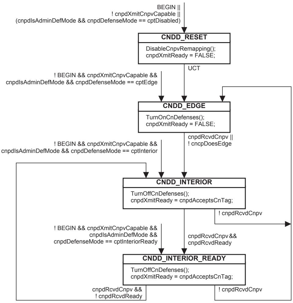
Figure 32-1—CND defense state machine
NOTE—In Figure 32-1, global transitions are associated with each value of cnpdDefenseMode when the CND defense mode is chosen by the managed variables; the nonglobal transitions from state to state can take place only when the CND defense mode is chosen by LLDP.
32.7 Congestion notification protocol
Clause 32 is a detailed specification of the state machines required to implement the QCN algorithm introduced in 30.2. Table 32-4 shows the correlation between the description of QCN in 30.2, the state machine variables in this clause, and the CNM PDU fields in 33.4.
There are two stateful participants in the congestion notification protocol. They are as follows:
a) The CP (31.1.1) shall behave in a manner that is indistinguishable, from an observer external to a system, from a strict implementation of the variables in 32.8 and the procedures in 32.9.
b) The RP (31.2.2.2) shall behave in a manner that is indistinguishable, from an observer external to a system, from a strict implementation of the timer in 32.12, variables in 32.13, the procedures in 32.14, and the state machine in 32.15.
Table 32-4—Correspondence of QCN and CCF message fields
<table><tr><td>Quantized Congestion Notification protocol, 30.2</td><td>Congestion notification protocol, 32.7</td><td>Congestion Notification Message, 33.3</td></tr><tr><td colspan="3">Quantized Feedback calculation (32.8.9, 32.9.4:e)</td></tr><tr><td><eq>F_b</eq> (30.2.1)</td><td>—</td><td>cpFb (33.4.3)</td></tr><tr><td><eq>Q_{off}</eq>(30.2.1)</td><td>– cpQOffset (32.8.7)</td><td>cnmQOffset (33.4.5)</td></tr><tr><td><eq>Q</eq> (30.2.1)</td><td>cpQLen (32.8.4)</td><td>—</td></tr><tr><td><eq>Q_{eq}</eq> (30.2.1)</td><td>cpQSp (32.8.3)</td><td>—</td></tr><tr><td><eq>Q_\delta</eq> (30.2.1)</td><td>cpQDelta (32.8.8)</td><td>cnmQDelta (33.4.6)</td></tr><tr><td><eq>Q_{old}</eq> (30.2.1)</td><td>cpQLenOld (32.8.5)</td><td>—</td></tr><tr><td>w (30.2.1)</td><td>cpW (32.8.6)</td><td>—</td></tr><tr><td colspan="3">RP rate calculations (32.14.5, 32.14.6, Figure 32-2)</td></tr><tr><td>CR (30.2.2)</td><td>rpCurrentRate (32.13.6)</td><td>—</td></tr><tr><td>TR (30.2.2)</td><td>rpTargetRate (32.13.5)</td><td>—</td></tr><tr><td>Byte Counter (30.2.3)</td><td>rpByteCount (32.13.2)</td><td>—</td></tr><tr><td>Timer (30.2.3)</td><td>RpWhile (32.12.1)</td><td>—</td></tr><tr><td><eq>G_d</eq> (30.2.2.1)</td><td>rpgGd (32.11.8)</td><td>—</td></tr><tr><td><eq>R_{AI}</eq> (30.2.2.1)</td><td>rpgAiRate (32.11.6)</td><td>—</td></tr><tr><td><eq>R_{HAI}</eq> (30.2.3)</td><td>rpgHaiRate (32.11.7)</td><td>—</td></tr><tr><td>i (30.2.3)</td><td>min(rpByteStage, rpTimeStage)(RPR_HYPER_INCREASE)</td><td>—</td></tr></table>
32.8 CP variables
The following variables control the operation of a CP:
a) cpMacAddress (32.8.1)
b) cpId (32.8.2)
c) cpQSp (32.8.3)
d) cpQLen (32.8.4)
e) cpQLenOld (32.8.5)
f) cpW (32.8.6)
g) cpQOffset (32.8.7)
h) cpQDelta (32.8.8)
i) cpFb (32.8.9)
j) cpEnqued (32.8.10)
k) cpSampleBase (32.8.11)
l) cpDiscardedFrames (32.8.12)
m) cpTransmittedFrames (32.8.13)
n) cpTransmittedCnms (32.8.14)
o) cpMinHeaderOctets (32.8.15)
32.8.1 cpMacAddress
The MAC address, belonging to the system transmitting the CNM PDU, used as the source_address of CNMs sent from this CP (32.9.4:b).
32.8.2 cpId
Unsigned integer. A number that uniquely identifies a CP in a Virtual Bridged Network (32.9.4:p).
NOTE—This standard does not specify whether the Congestion Point Identifier (CPID) reported in a CNM by a CP that serves multiple CNPVs does or does not have the same value for its different CNPVs.
32.8.3 cpQSp
Unsigned integer. The set-point for the queue. This is the target number of octets in the CP’s queue (32.9.4:e). Default value 26000.
32.8.4 cpQLen
Unsigned integer. The current number of octets in the CP’s queue (32.9.4:c).
32.8.5 cpQLenOld
Unsigned integer. The previous value of cpQLen. cpQLenOld is updated from cpQLen each time GenerateCnmPdu() is called (32.9.4:c).
32.8.6 cpW
Real number. cpW is the weight to be given to the change in queue length in the calculation of cpFb (32.8.9). Default value 2. Although cpW is specified as a real number, it is constrained to be a power of 2, e.g., 1/2, 1, 2, 4. In practice, therefore, it can be represented as a shift distance (plus an addition) in 32.9.4:e.
32.8.7 cpQOffset
The signed integer value of the transmitting CP’s cpQSp (32.8.3) – cpQLen (32.8.4) used to calculate cpFb (32.8.9), and thus the Quantized Feedback field (33.4.3).
32.8.8 cpQDelta
The signed integer value of the transmitting CP’s cpQLen (32.8.4) – cpQLenOld (32.8.5) used to calculate cpFb (32.8.9), and thus the Quantized Feedback field (33.4.3).
32.8.9 cpFb
Signed integer. Calculated just before the CP attempts to enqueue a frame:
$$
\mathrm{cpFb} = \mathrm{cpQOffset} - \mathrm{cpW} \times \mathrm{cpQDelta},
$$
where
$$
\mathrm{cpQDelta} = \mathrm{cpQLen} - \mathrm{cpQLenOldcpQOffset} = \mathrm{cpQSp} - \mathrm{cpQLen}
$$
cpFb has two terms. The first term is the difference between the current and the desired queue lengths (cpQOffset, 32.8.7). The second is a weight factor cpW times the difference cpQDelta (32.8.8) between the current and the previous queue lengths. Thus, a multiple of the first derivative of the queue size is subtracted from the current nonoptimality of the queue, so that if the queue length is moving toward the set point cpQSp, cpFb will be closer to 0 than if the queue length is moving away from cpQSp.
32.8.10 cpEnqued
Signed integer. The number of octets remaining to be enqueued by the CP before a CNM PDU is to be generated (32.9.3).
32.8.11 cpSampleBase
Unsigned integer. The minimum number of octets to enqueue in the CP’s queue between CNM PDU transmissions (32.9.3). Default value 150 000.
32.8.12 cpDiscardedFrames
The number of frames offered to this CP that were discarded because of a full output queue (31.1.1).
32.8.13 cpTransmittedFrames
The number of data frames enqueued for transmission on this CP’s output queue (31.1.1).
32.8.14 cpTransmittedCnms
The number of CNMs transmitted by this CP (32.9.4:s).
32.8.15 cpMinHeaderOctets
The minimum number of octets that the CP is to return in theEncapsulated MSDU field (33.4.10) of each CNM it generates (32.9.4:k). Default value 0.
32.9 CP procedures
The procedures used in a CP include the following:
a) Random() (32.9.1)
b) NewCpSampleBase() (32.9.2)
c) EM_UNITDATA.request (parameters) (32.9.3)
d) GenerateCnmPdu() (32.9.4)
A CP needs no state machine; the procedure EM_UNITDATA.request (parameters), called each time a frame is presented for queuing, triggers all of the CP’s functions.
32.9.1 Random
The Random function takes two parameters, min and max, and returns a pseudo-random number in the range min ≤ number < max. This function shall be initialized so that it generates a different value each time the system is reset.
32.9.2 NewCpSampleBase()
Called by EM_UNITDATA.request (parameters) (32.9.3) when generating a new value for cpSampleBase (32.8.11) from the CNM PDU Quantized Feedback field (33.4.3) last generated by GenerateCnmPdu(). NewCpSampleBase() returns a real number according to Table 32-5.
Table 32-5—NewCpSampleBase() return value as a function of cpFb
<table><tr><td>Quantized Feedback / 8</td><td>Value returned by NewCpSampleBase()</td></tr><tr><td>0</td><td>1</td></tr><tr><td>1</td><td>1/2</td></tr><tr><td>2</td><td>1/3</td></tr><tr><td>3</td><td>1/4</td></tr><tr><td>4</td><td>1/5</td></tr><tr><td>5</td><td>1/6</td></tr><tr><td>6</td><td>1/7</td></tr><tr><td>7</td><td>1/8</td></tr></table>
NOTE—The values in Table 32-5 are chosen so that the value returned by NewCpSampleBase() can be an integer to be used in a division, rather than a real number to be used in a multiplication.
32.9.3 EM_UNITDATA.request (parameters)
A CP offers an instance of the EISS (6.8) to the Queuing frames function (8.6.6). When called upon to enqueue a frame, the CP
a) Determines the number of octets of buffer space required to enqueue the frame, and subtracts that number from cpEnqued (32.8.10)
b) If cpEnqued ≤ 0, then the CP:
1) Calculates a new value for cpFb according to 32.8.9
2) Calls GenerateCnmPdu() to conditionally transmit a CNM PDU
3) Replaces cpEnqued with cpSampleBase NewCpSampleBase() Random(0.85, 1.15), and if the result is less than zero, resets cpEnqued to 0
The accuracy of the sample jitter introduced by the function Random(0.85, 1.15) is not critical to the success of congestion notification. The amount of jitter introduced by this function should be no more than 0.75 ≤ jitter < 1.25 and no less than 0.875 ≤ jitter < 1.125.
32.9.4 GenerateCnmPdu()
Called by the CP to conditionally generate a CN-TAGged CNM PDU for output. GenerateCnmPdu():
a) Uses the source_address of the frame triggering the CNM PDU as the destination_address of the generated CNM PDU.
b) Uses cpMacAddress (32.8.1) as the source_address of the CNM PDU.
c) Replaces the value of cpQLenOld (32.8.5) with cpQLen (32.8.4).
d) If cpFb is greater than or equal to 0, or if the destination_address parameter of the CNM PDU is a Group, and not an Individual, address, does nothing; no further processing takes place, and no CNM PDU is transmitted.
e) Fills the Quantized Feedback field (33.4.3) of the CNM PDU as follows:
$$
\text { if } (\mathrm{cpFb} < - \mathrm{cpQSp} \times (2 \times \mathrm{cpW} + 1))
$$
$$
\text { Quantized Feedback } = 6 3
$$
else
$$
\text { Quantized Feedback } = - \mathrm{cpFb} \times 6 3 / (\mathrm{cpQSp} \times (2 \times \mathrm{cpW} + 1))
$$
f) If the Quantized Feedback field equal to 0 does nothing; no further processing takes place, and no CNM PDU is transmitted.
g) If the first octets of the mac_service_data_unit of the frame triggering the CNM PDU are a CN-TAG, copies the Flow Identifier field (33.2.1) from that CN-TAG to the CN-TAG of the CNM, else fills the Flow Identifier field of the CNM’s CN-TAG with 0.
h) Sets the priority parameter of the CNM PDU from cngCnmTransmitPriority (32.2.2).
NOTE 1—The default value for the priority of a CNM PDU is 6. CNM PDUs are not expected to be sent in high volumes, but undelivered CNM PDUs reduce the ability of congestion notification to prevent lost data frames. Priority 7 is typically reserved for control traffic that, if not delivered, can result in the loss of connectivity in the Bridged Network.
i) Sets the vlan_identifier of the CNM PDU from the vlan_identifier of the frame triggering the CNM PDU, if the dot1agCfmVlanTable is not implemented, else the Primary VID of that vlan_identifier.
j) Fills the Encapsulated destination MAC address field (33.4.8) of the CNM PDU with the destination_address parameter of the frame triggering the CNM PDU.
k) Fills the Encapsulated MSDU field (33.4.10) of the CNM PDU with the first octets of the remainder of the mac_service_data_unit following the CN-TAG, if present, of the frame triggering the CNM PDU. The minimum number of octets is the value of cpMinHeaderOctets (32.8.15), or the whole of the mac_service_data_unit following the CN-TAG, if it is shorter, and the maximum is 64.
l) Fills the Encapsulated MSDU length field (33.4.9) of the CNM PDU with the number of octets inserted into the Encapsulated MSDU field (33.4.10).
m) Inserts the encapsulation appropriate to the CP’s port, as specified in 33.3, at the beginning of the mac_service_data_unit.
NOTE 2—This encapsulation is changed by the Bridge, if required, before the CNM PDU is output on a port that uses a different encapsulation from the CP’s port.
n) Fills the Version field (33.4.1) of the CNM PDU with 0.
o) Fills the ReservedV field (33.4.2) of the CNM PDU with 0.
p) Fills the Congestion Point Identifier field (33.4.4) of the CNM PDU from the variable cpId (32.8.2).
q) Computes and fills the cnmQOffset and cnmQDelta fields (33.4.5, 33.4.6) from the variables cpQOffset and cpQDelta.
r) Fills the Encapsulated priority field (33.4.7) from the priority parameter of the frame triggering the CNM PDU.
s) Increments cpTransmittedCnms (32.8.14).
t) Passes the CN-TAG and CNM PDU as an EM_UNITDATA.indication to the higher layers (Figure 31-1), if the CP is in a Bridge, or to the Flow multiplexer (31.2.4), if the CP is in an end station (Figure 31-2).
32.10 RP per-Port per-CNPV variables
There is one set of these variables per Port per CNPV in a congestion aware end station. A set of RP per-Port per-CNPV variables is created or deleted whenever a CN Port priority managed object is created or deleted. All of the RPs (if more than one) associated with a given Port and CNPV share a single set of the RP per-Port per-CNPV variables.
32.10.1 rpppMaxRps
An unsigned integer controlling the maximum number of RPs allowed for this CNPV on this Port (default 1). An end station shall not create more than rpppMaxRps on a given Port, but it can create fewer.
32.10.2 rpppCreatedRps
The number of times an RP’s rpEnabled variable has been set TRUE at this priority level on this Port (32.14.4:e).
32.10.3 rpppRpCentiseconds
An integer containing the number of RP-centiseconds accumulated by RPs at this priority level on this Port. This variable is incremented once per centisecond (10 ms) for each RP on this Port whose rpEnabled variable (32.13.1) is TRUE.
NOTE—Reading rpppRpCentiseconds and SysUpTime38 at two different times allows a management entity to compute the average number of RPs present for a priority and Port by dividing the change in rpppRpCentiseconds by the change in SysUpTime (which is measured in centiseconds).
32.11 RP group variables
There is one set of RP group variables for each group of RPs belonging to a particular CNPV on a Port in a congestion aware end station. It is an implementation choice whether each RP rate control state machine (32.15) has its own set of RP group variables or shares them with another RP rate control state machine on the same Port and the same CNPV. This standard does not specify how RPs are grouped together for management purposes, except that all of the RPs controlled by a single set of RP group variables shall serve a single CNPV. At the extremes, a single set of RP group variables could control all of the RPs serving the same CNPV, or each RP could be controlled by its own set of RP group variables. The RP group variables include the following:
a) rpgEnable (32.11.1)
b) rpgTimeReset (32.11.2)
c) rpgByteReset (32.11.3)
d) rpgThreshold (32.11.4)
e) rpgMaxRate (32.11.5)
f) rpgAiRate (32.11.6)
g) rpgHaiRate (32.11.7)
h) rpgGd (32.11.8)
i) rpgMinDecFac (32.11.9)
j) rpgMinRate (32.11.10)
32.11.1 rpgEnable
A Boolean value controlling the rpEnabled variables for all of the RP rate control state machines controlled by this Reaction Point group managed object. If rpgEnable is TRUE, the controlled rpEnabled variables are not held in the FALSE state, thus enabling the RPs to pay attention to received CNMs. If rpgEnable is FALSE, the controlled rpEnabled variables are held in the FALSE state, thus disabling the RPs.
32.11.2 rpgTimeReset
Unsigned integer. RpWhile (32.12.1) is reset to either rpgTimeReset or rpgTimeReset / 2 (with random jitter—see Figure 32-2, RPR_ACTIVE_TIME) each time it reaches 0, according to the state of the RP rate control state machine. Default value 15 ms.
32.11.3 rpgByteReset
Unsigned integer. rpByteCount (32.13.2) is reset to either rpgByteReset or rpgByteReset / 2 (with random jitter—see Figure 32-2, RPR_ACTIVE_BYTE) each time it reaches 0, according to the state of the RP rate control state machine. Default value 150 000 octets.
32.11.4 rpgThreshold
Unsigned integer. Specifies the number of times rpByteStage or rpTimeStage can count before the RP rate control state machine advances states. Default value is 5.
32.11.5 rpgMaxRate
Unsigned integer. The maximum rate, in bits per second, at which an RP can transmit. Default value is the speed of the Port. A system shall support a nonzero minimum value for rpgMaxRate no larger than 5 Mbit/s. This rate includes all bits consequent to transmitting the frame on the LAN, including preamble, inter-frame gap, etc. rpgMaxRate is configurable in multiples of 1 Mbit/s.
32.11.6 rpgAiRate
Unsigned integer. The rate, in bits per second, used to increase rpTargetRate in the RPR_ACTIVE_INCREASE state in Figure 32-2. Default value 5 Mbit/s. This rate includes all bits consequent to transmitting the frame on the LAN, including preamble, inter-frame gap, etc. rpgAiRate is configurable in multiples of 1 Mbit/s.
32.11.7 rpgHaiRate
Unsigned integer. The rate, in bits per second, used to increase rpTargetRate in the RPR_HYPER_INCREASE state in Figure 32-2. Default value 50 Mbit/s. This rate includes all bits consequent to transmitting the frame on the LAN, including preamble, inter-frame gap, etc. rpgHaiRate is configurable in multiples of 1 Mbit/s.
32.11.8 rpgGd
Real number. Multiplied times the Quantized Feedback field (33.4.3) received in a CNM PDU to decrease rpTargetRate. Default value 1/128. rpgGd is configurable as a power of 2, e.g., 1/256, 1/128, 1/64.
32.11.9 rpgMinDecFac
Real number. The minimum factor by which the current RP transmit rate rpCurrentRate can be changed by reception of a CNM. Default value is 0.5.
32.11.10 rpgMinRate
Unsigned integer. The minimum value, in bits per second, for rpCurrentRate (32.13.6) Default value is 10 Mbit/s. A system shall support a minimum value for rpgMinRate no larger than 10 Mbit/s. This rate includes all bits consequent to transmitting the frame on the LAN, including preamble, inter-frame gap, etc. rpgMinDecFac is configurable in multiples of 1 Mbit/s.
32.12 RP timer
An RP implements one timer as follows:
a) RpWhile (32.12.1).
32.12.1 RpWhile
Timer counter for controlling the RP rate control state machine (32.15). RpWhile operates normally when rpFreeze (32.13.7) is FALSE, and shall not be decremented when rpFreeze is TRUE.
32.13 RP variables
Each RP rate control state machine (32.15) has its own set of RP variables. The RP variables include the following:
a) rpEnabled (32.13.1)
b) rpByteCount (32.13.2)
c) rpByteStage (32.13.3)
d) rpTimeStage (32.13.4)
e) rpTargetRate (32.13.5)
f) rpCurrentRate (32.13.6)
g) rpFreeze (32.13.7)
h) rpLimiterRate (32.13.8)
i) rpFb (32.13.9)
32.13.1 rpEnabled
Boolean. Controls RP rate control state machine. If TRUE, state machine is running. If FALSE, state machine is held in the RPR_RESET state. Initialized to FALSE when an RP rate control state machine is created. Held in the FALSE state if rpgEnable (32.11.1) has the value FALSE.
32.13.2 rpByteCount
Unsigned integer. Counts octets passed from the Rate Limiter (31.2.2.4) to the Flow Selection function (31.2.2.5). The counting down of rpByteCount to or past 0 triggers a reevaluation of rpCurrentRate (32.13.6).
32.13.3 rpByteStage
Unsigned integer. Counts the number of times rpByteCount has counted down to or past 0 since the last CNM was received.
32.13.4 rpTimeStage
Unsigned integer. Counts the number of times RpWhile has counted down to 0 since the last CNM was received.
32.13.5 rpTargetRate
Unsigned integer. The target rate, in bits per second, toward which rpCurrentRate is heading. This rate includes all bits consequent to transmitting the frame on the LAN, including preamble, inter-frame gap, etc.
32.13.6 rpCurrentRate
Unsigned integer. The rate, in bits per second, at which the Rate Limiter (31.2.2.4) transmits data from its Flow queue when rpFreeze (32.13.7) is FALSE. (The actual output of the Rate Limiter is controlled by rpLimiterRate, 32.13.8.) This rate includes all bits consequent to transmitting the frame on the LAN, including preamble, inter-frame gap, etc.
32.13.7 rpFreeze
Boolean. When FALSE, the RP and Rate Limiter operate normally. When TRUE, rpLimiterRate is held to the value 0, to suppress the transmission of frames. rpFreeze is FALSE when there is room for frames from this RP in the output queue, and TRUE when not.
32.13.8 rpLimiterRate
Unsigned integer. The rate, in bits per second, at which the Rate Limiter (31.2.2.4) transmits data from its Flow queue. rpLimiterRate is equal to rpCurrentRate (32.13.6) as long as rpFreeze (32.13.7) is FALSE, and 0, when rpFreeze is TRUE. This rate includes all bits consequent to transmitting the frame on the LAN, including preamble, inter-frame gap, etc.
32.13.9 rpFb
Unsigned integer. The value last received in the Quantized Feedback field (33.4.3) of a CNM PDU or 0.
32.14 RP procedures
The following procedures are used by the RP rate control state machine and the Output flow segregation function (31.2.1):
a) ResetCnm (32.14.1)
b) TestRpTerminate (32.14.2)
c) TransmitDataFrame (32.14.3)
d) ReceiveCnm (32.14.4)
e) ProcessCnm (32.14.5)
f) AdjustRates (32.14.6)
32.14.1 ResetCnm
Called whenever the RP rate control state machine enters the RPR_RESET state (Figure 32-2) to set the following variables:
rpCurrentRate = rpgMaxRate
rpTargetRate = rpgMaxRate
rpByteCount = rpgByteReset
rpFb = 0
32.14.2 TestRpTerminate
Called by the Flow Selection function (31.2.2.5) each time a frame is passed from the Per-CNPV station function’s Rate Limiter (31.2.2.4) to the Flow multiplexer (31.2.4). If
a) rpCurrentRate equals rpgMaxRate
b) The Flow queue is empty
c) rpEnabled is TRUE
Then TestRpTerminate sets rpEnabled (32.13.1) to FALSE, which disables the RP until another CNM is received.
NOTE—Condition b) can be met when all frames limited by a given Rate Limiter have been processed. See 31.2.2.1.
32.14.3 TransmitDataFrame
TransmitDataFrame() is called each time a frame is passed from a Rate Limiter (31.2.2.4) to the Port’s Flow multiplexer (31.2.4). TransmitDataFrame() subtracts the length of the transmitted frame from rpByteCount (32.13.2) and may insert a CN-TAG containing the Flow ID of the Flow queue at the beginning of the frame’s mac_service_data_unit.
If an end station is VLAN-aware or priority-aware, and if a CN-TAG is added to a frame, the CN-TAG shall follow the VLAN or priority tag in the frame.
32.14.4 ReceiveCnm
Called whenever a CNM is received. ReceiveCnm() performs the following actions:
a) The CNM is validated according to 33.4.11 and is discarded if invalid.
b) If the CNM frame carries a CN-TAG (33.2), the Flow ID from that CN-TAG (33.2.1) is used to identify the particular RP rate control state machine to which this CNM applies.
c) If the receiving end station is unable to identify the particular RP rate control state machine to which this CNM applies, it discards the CNM, and no further processing takes place.
d) Sets the rpFb variable from the CNM’s Quantized Feedback field (33.4.3).
e) If the selected RP rate control state machine’s rpEnabled variable is FALSE and is not held FALSE because rpgEnable (32.11.1) has the value FALSE, and the CNM’s cnmQOffset field (33.4.5) is negative, then rpEnabled is reset to TRUE, the variable rpppCreatedRps (32.10.2) is incremented.
These actions activate the selected RP rate control state machine, if it was not active (rpEnabled == FALSE), and also cause the RP rate control state machine to process the received CNM.
32.14.5 ProcessCnm
Called whenever the RP rate control state machine enters the RPR_CNM_RECEIVED state (Figure 32-2) to perform the following actions:
if (rpByteStage != 0) {
rpTargetRate = rpCurrentRate;
rpByteCount = rpgByteReset;
}
rpByteStage = 0;
rpTimeStage = 0;
dec_factor = (1 - (rpgGd * rpFb));
if (dec_factor < rpgMinDecFac)
dec_factor = rpgMinDecFac;
rpCurrentRate = rpCurrentRate * dec_factor;
if (rpCurrentRate < rpgMinRate)
rpCurrentRate = rpgMinRate;
RpWhile = rpgTimeReset;
32.14.6 AdjustRates
AdjustRates is called whenever the RPR_ADJUST_RATES, RPR_ACTIVE_INCREASE, or RPR_HYPER_INCREASE states are entered. It takes one parameter, increase, that specifies how much to increase rpTargetRate, and performs the following actions:
if ((rpByteStage == 1) || (rpTimeStage == 1)) && (rpTargetRate > 10 * rpCurrentRate))
rpTargetRate = rpTargetRate / 8;
else
rpTargetRate = rpTargetRate + increase;
rpCurrentRate = (rpTargetRate + rpCurrentRate)/2;
if (rpCurrentRate > rpgMaxRate)
rpCurrentRate = rpgMaxRate;
32.15 RP rate control state machine
The RP rate control state machine is illustrated in Figure 32-2.
In this figure, the RPR_RESET state has no exit. The state machine is held in the RPR_RESET state as long as either the general system initialization variable “BEGIN” is TRUE or the rpEnabled variable, local to the particular instance of the RP rate control state machine, is FALSE. When “BEGIN” becomes FALSE and rpEnabled TRUE, the state machine remains in the RPR_RESET state until a CNM is received by ReceiveCnm (32.14.4) with a Quantized Feedback field (33.4.3) that is less than 0. ReceiveCnm places that field into rpFb (32.13.9), which condition forces the state machine into the RPR_CNM_RECEIVED state. When that state resets rpFb to 0, progress through the state machine continues either until another CNM is received and rpFb is set to a nonzero value, or until the state machine is deactivated by TestRpTerminate (32.14.2) setting rpEnabled to FALSE.
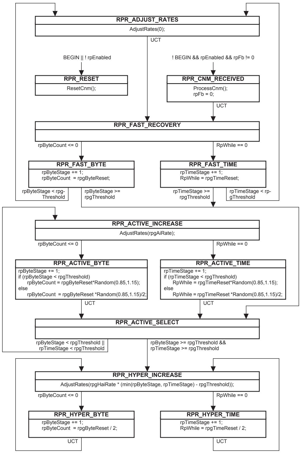
Figure 32-2—RP rate control state machine
32.16 Congestion notification and encapsulation interworking function
As mentioned in 30.8, a hierarchical Bridged Network, e.g., a PBBN, can require a congestion notification and encapsulation interworking function for a CP in the core of the network to generate a CNM that can reach the RP, which is presumably outside the core. This general case is illustrated in Figure 32-3. In the network illustrated, encapsulation and decapsulation functions peer with each other to encapsulate the data frames inside some kind of wrapper, e.g., an S-TAG and/or an I-TAG.
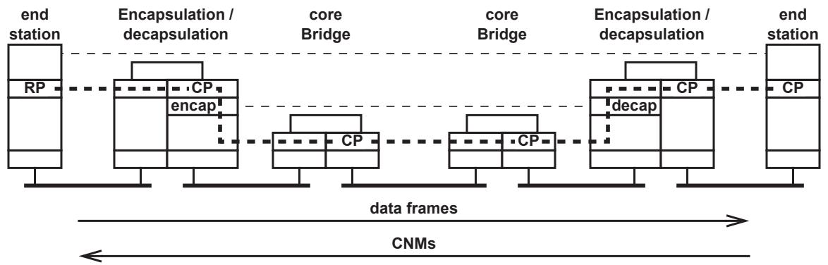
Figure 32-3—CP–RP peering in any hierarchical Bridged Network
Not all encapsulation schemes are equivalent. It is useful to divide hierarchical Bridged Networks into two categories for the purpose of defining congestion notification and encapsulation interworking functions, based on the mac_service_data_unit of a data frame carrying (optionally) a CN-TAG as seen by a CP residing in a core Bridge, with one of these cases further subdivided as follows:
a) In a network where the original end station’s mac_service_data_unit, including the optional CN-TAG, comprises the first octets of the mac_service_data_unit at the core Bridge’s CP, there is no need for a congestion notification and encapsulation interworking function. For example, a PBN in which the C-TAGs are not carried across the core needs no interworking function.
b) In a network where an encapsulation comprises the first octets of the mac_service_data_unit at the core Bridge’s CP, a congestion notification and encapsulation interworking function is required. It is useful to make a further distinction, in this case:
1) The MAC addresses of Ports in the Bridges where the encapsulation and decapsulation functions are performed are the destination and source addresses of frames crossing the core Bridges. For example, in a PBBN, the I-TAG, and perhaps an S-TAG and/or a C-TAG as well, can be present as the first octets of the mac_service_data_unit, and the source_address and destination_address parameters visible to the core Bridge’s CP are the addresses of PIPs in BEBs.
2) In other networks, although an encapsulation is in the first octets of the mac_service_data_unit at the core Bridge’s CP, the source and destination MAC addresses are not altered by the encapsulation and decapsulation operations. For example, in a PBN in which both a C-TAG and an S-TAG are carried across the core, the C-TAG occupies the first octets of the mac_service_data_unit as seen by a core Bridge’s CP.
In either type of network covered by case b, the core Bridge’s CP is configured by the network administrator to return, in the Encapsulated MSDU field of the CNM PDU (33.4.10), the leading octets of the mac_service_data_unit of the data frame triggering transmission of the CNM. Since the CN-TAG of the data frame, if present, is buried behind encapsulations unknown to the CP, when the CN-TAG and CNM are built according to 32.9.4, the Flow ID returned in the CN-TAG of the CNM is filled with 0. The network administrator configures the CP to return at least enough octets of the data frame’s mac_service_data_unit to include the CN-TAG of the original data frame transmitted by the RP.
The difference between case 1 and case 2, preceding, lies in the means used by the Port containing the congestion notification and encapsulation interworking function to recognize the CNM in order to translate it. In case 1, the CNM is addressed to that Port, and has a CN-TAG and the CNM encapsulation, instead of a data frame tag and encapsulation. In case 2, the only reliable indicator of a CNM that needs to be transformed, as opposed for example, to a CNM returned by the destination end station’s CP, can be the presence of an encapsulation known to the interworking function in the Encapsulated MSDU field (33.4.10) of the CNM PDU.
When the CNM generated by the core Bridge’s CP reaches a congestion notification and encapsulation interworking function, that interworking function uses the information in the CNM PDU, including the encapsulated data frame information, to construct a CN-TAG and CNM PDU to send to the RP. The steps taken are as follows:
c) In case 1, where the CNM is returned to the MAC address of the interworking function’s Port, the destination_address parameter is obtained from the appropriate source address found in the Encapsulated MSDU field, and the source_address parameter is a MAC address belonging to the Bridge containing the interworking function, and valid in the context of the newly generated CNM, for example, a management port address.
d) In case 2, where the CNM is recognized by the presence of the encapsulation in the Encapsulated MSDU field, the source_address, and destination_address parameters are unchanged.
e) The vlan_identifier is obtained from the Encapsulated MSDU field.
f) The drop_eligible parameter is False.
g) The priority parameter used is the value configured for a CP on a Port in the Bridge in which the interworking function resides, and through which the CNM passes.
h) The Encapsulated priority field (33.4.7) is obtained from the Encapsulated MSDU field, or if not present there, the Encapsulated priority is left unchanged.
NOTE—In spite of the provisions for CND defense in this clause, it is possible for a network administrator to configure a network so that the priority of a CCF data frame is not preserved. For example, in a PBN, two CNPVs could be mapped to the same S-TAG priority, and the C-TAG not configured to be carried across the network. In that case, an end station with an RP on each of those CNPVs, and that does not distinguish between those RPs using CN-TAGs, would be unable to assign returned CNMs to the right RP. At least some of its CCFs would not be constrained, and uncontrolled congestion would likely result. It is therefore recommended that the CN-TAG be included across a PBN, or that each CNPV be mapped to a separate priority in the backbone.
i) If a CN-TAG is found in the Encapsulated MSDU, its Flow ID is copied to the CN-TAG of the newly generated CNM, else 0 is used for that CN-TAG’s Flow ID.
j) The encapsulation in the Encapsulated MSDU field of the CNM PDU, up to and including the CN-TAG (which is not necessarily present), is elided, the remainder (if any) of the Encapsulated MSDU field moved up to the first octets of the field, and the Encapsulated MSDU length field reduced accordingly.
33 Encoding of congestion notification PDUs
This clause specifies the method of encoding congestion notification PDUs. The specifications include the following:
a) The general structure and encoding of congestion notification PDUs (33.1).
b) The format used for the CN-TAG (33.2).
c) The encapsulation used for a CNM (33.3).
d) The format used for the CNM (33.4).
The format of the IEEE Std 802.1AB-2009 Type Length Value (TLV) used to signal that a VLAN Bridge or end station is congestion aware, and the state of its CND defense mode, is specified in D.2.8.
NOTE—Clause 30 introduces the principles of congestion notification operation and the network architectural concepts that support it. Clause 31 breaks down the congestion notification entities into their components. Clause 32 specifies the protocols operated by these components.
33.1 Structure, representation, and encoding
All congestion notification PDUs contain an integral number of octets.
The octets in a congestion notification PDU are numbered starting from 1 and increasing in the order they are put into the MSDU that accompanies a request to or indication from the instance of the MAC Internal Sublayer Service (ISS or EISS) used by a congestion notification entity.
The bits in an octet are numbered from 1 to 8 in order of increasing bit significance, where 1 is the LSB in the octet.
Where octets and bits within a congestion notification PDU are represented using a diagram, octets shown higher on the page than subsequent octets and octets shown to the left of subsequent octets at the same height on the page are lower numbered; bits shown to the left of other bits within the same octet are higher numbered.
Where two or more consecutive octets are represented as hexadecimal values, lower numbered octet(s) are shown to the left and each octet following the first is preceded by a hyphen, e.g., 01-80-C2-00-00-00.
When consecutive octets are used to encode a binary number, the lower octet number has the more significant value. When consecutive bits within an octet are used to encode a binary number, the higher bit number has the most significant value. When bits within consecutive octets are used to encode a binary number, the lower octet number composes the more significant bits of the number. A flag is encoded as a single bit, and is set (TRUE) if the bit takes the value 1, and clear (FALSE) otherwise. The remaining bits within the octet can be used to encode other protocol fields.
33.2 CN-TAG format
The means for identifying CN-TAG PDUs depend on the medium. For media using a Length/Type field, e.g., IEEE 802.3 media, the identification consists of two octets containing the EtherType value shown (in hexadecimal notation) in Table 33-1. Media requiring an LLC encapsulation (e.g., IEEE 802.11) use the SNAP encoding shown (in hexadecimal notation) in Table 33-2.
Table 33-1—CN-TAG Encapsulation: Length/Type Media
<table><tr><td></td><td>Octet</td><td>Length</td></tr><tr><td>Tag EtherType (0x22E9)</td><td>1</td><td>2</td></tr><tr><td>Flow Identifier</td><td>3</td><td>2</td></tr></table>
Table 33-2—CN-TAG Encapsulation: LLC Media
<table><tr><td></td><td>Octet</td><td>Length</td></tr><tr><td>0xAAAA03</td><td>1</td><td>3</td></tr><tr><td>0x000000</td><td>4</td><td>3</td></tr><tr><td>Tag EtherType (0x22E9)</td><td>7</td><td>2</td></tr><tr><td>Flow Identifier</td><td>9</td><td>2</td></tr></table>
In a VLAN Bridge, the shim that supports the EISS (IEEE Std 802.1AC, 6.8, Figure 22-4) is below the Queuing shim (8.6.6, 8.6.7, 8.6.8, 31.1.1). The CN-TAG is examined by the CP, which is part of the Queuing shim. Therefore, the CN-TAG will be further from the source_address and destination_address fields, and closer to the end of the frame, than a VLAN tag added by 6.8, if any. In order for a Bridge to be able to recognize the CN-TAG in a data frame, an end station shall insert the CN-TAG and VLAN tag in the relative order required by a Bridge: addresses, VLAN tag, CN-TAG, data.39
33.2.1 Flow Identifier
The meaning and encoding of the Flow Identifier field are not specified by this standard. A CP shall not interpret the value in a Flow Identifier field. The Flow ID returned in the CN-TAG of a CNM is used by an end station’s CNM demultiplexer (31.2.5) to identify the RP, the Flow queue, or a group of one or more individual flows, from which was transmitted the data frame that triggered the CNM.
33.3 Congestion Notification Message (CNM)
The means for identifying Congestion Notification Message PDUs depend on the medium. For media using a Length/Type field, e.g., IEEE 802.3 media, the identification consists of two octets containing the EtherType value shown (in hexadecimal notation) in Table 33-3. Media requiring an LLC encapsulation (e.g., IEEE 802.11) use the SNAP encoding shown (in hexadecimal notation) in Table 33-4.
Table 33-3—CNM Encapsulation: Length/Type Media
<table><tr><td></td><td>Octet</td><td>Length</td></tr><tr><td>PDU EtherType (0x22E7)</td><td>1</td><td>2</td></tr><tr><td>CNM PDU</td><td>3</td><td>24 to 88</td></tr></table>
Table 33-4—CNM Encapsulation: LLC Media
<table><tr><td></td><td>Octet</td><td>Length</td></tr><tr><td>0xAAAA03</td><td>1</td><td>3</td></tr><tr><td>0x000000</td><td>4</td><td>3</td></tr><tr><td>PDU EtherType (0x22E7)</td><td>7</td><td>2</td></tr><tr><td>CNM PDU</td><td>9</td><td>24 to 88</td></tr></table>
33.4 Congestion Notification Message PDU format
The format of a Congestion Notification Message (CNM) PDU is illustrated in Table 33-5. If the frame that triggered the transmission of the CNM carried a CN-TAG, then that CN-TAG is retained in the frame carrying the CNM PDU; otherwise, a CN-TAG with a FlowID of 0 is used in the frame carrying the CNM PDU.
Table 33-5—Congestion Notification Message PDU
<table><tr><td></td><td>Octet</td><td>Length</td></tr><tr><td>Version</td><td>1</td><td>4 bits</td></tr><tr><td>ReservedV</td><td>1, 2</td><td>6 bits</td></tr><tr><td>Quantized Feedback</td><td>2</td><td>6 bits</td></tr><tr><td>Congestion Point Identifier</td><td>3</td><td>8</td></tr><tr><td>cnmQOffset</td><td>11</td><td>2</td></tr><tr><td>cnmQDelta</td><td>13</td><td>2</td></tr><tr><td>Encapsulated priority</td><td>15</td><td>2</td></tr><tr><td>Encapsulated destination MAC address</td><td>17</td><td>6</td></tr><tr><td>Encapsulated MSDU length</td><td>23</td><td>2</td></tr><tr><td>Encapsulated MSDU</td><td>25</td><td>0–64</td></tr></table>
33.4.1 Version
This field, 4 bits in length, shall be transmitted with the value 0, and shall be ignored on receipt. The Version field occupies the most significant bits of the first octet of the CNM PDU.
33.4.2 ReservedV
This field, 6 bits in length, shall be transmitted with the value 0, and shall be ignored on receipt. The ReservedV field occupies the least significant 4 bits of the first octet, and the most significant 2 bits of the second octet, of the CNM PDU.
33.4.3 Quantized Feedback
This field, 6 bits in length, contains the Quantized Feedback value calculated by the CP’s EM_UNITDATA.request (parameters) procedure (32.9.3). The Quantized Feedback field occupies the least significant bits of the first two octets of the CNM PDU.
33.4.4 Congestion Point Identifier
This field, 8 octets in length, uniquely identifies the CP that triggered the transmission of this Congestion Notification Message PDU format within the CND. Because the transmitting system can format the Congestion Point Identifier (CPID) in any manner, a receiving RP shall not assign any meaning to subfields within a CPID.
NOTE—Making the CPID 8 octets long removes the connection between CP identity and the source MAC address of the CNM PDU. One way to achieve the requirements for uniqueness of the CPID would be to use a Port’s MAC address as the high-order 6 octets of the CPID, and use the low-order two octets of the CPID to hold the priority of the CP’s queue and/or an indication of the physical port.
33.4.5 cnmQOffset
The twos-complement signed integer value of the transmitting CP’s cpQOffset (32.8.7) in units of 64 octets. This standard does not specify whether cpQOffset is rounded or truncated to obtain cnmQOffset. If the value of cpQOffset is less than –32768, a value of –32768 is used in cpQOffset, and if greater than 32767, 32767 is used.
33.4.6 cnmQDelta
The twos-complement signed integer value of the transmitting CP’s cpQDelta (32.8.8) in units of 64 octets. This standard does not specify whether cpQDelta is rounded or truncated to obtain cnmQDelta. If the value of cpQDelta is less than –32768, a value of –32768 is used in cnmQDelta, and if greater than 32767, 32767 is used.
NOTE—Although cnmQDelta is not used by the RP, it is included in the CNM PDU to aid the network administrator when adjusting configuration parameters.
33.4.7 Encapsulated priority
This field, 2 octets in length, contains the priority parameter of the frame that triggered the transmission of this CNM in the most significant 3 bits of the field. The remaining bits of the field are transmitted as 0, and ignored on receipt.
33.4.8 Encapsulated destination MAC address
This field, 6 octets in length, contains the destination_mac_address parameter of the frame that triggered the transmission of this CNM.
33.4.9 Encapsulated MSDU length
This field, 2 octets in length, contains the number of octets returned in the Encapsulated MSDU field (33.4.10).
33.4.10 Encapsulated MSDU
This field, a maximum of 64 octets in length, contains the initial octets of the mac_service_data_unit of the frame that triggered the transmission of this CNM.
33.4.11 CNM Validation
A CNM PDU received by a CNM demultiplexer (31.2.5) shall be considered invalid and be discarded if the following condition is TRUE:
a) There are fewer than 24 octets in the mac_service_data_unit.
A CNM PDU received by a CNM demultiplexer (31.2.5) may be considered invalid and be discarded if the following condition is TRUE:
b) The CNM PDU has no CN-TAG.
NOTE 1—The variable cnpdAcceptsCnTag (32.4.10), when set FALSE in an end station, indicates to the neighboring Bridge that the CN-TAG is to be removed from all frames, including CNMs, transmitted to the end station. It is not recommended that an end station set cnpdAcceptsCnTag to FALSE if this would result in the end station discarding CNMs for lack of a CN-TAG.
The following condition shall not cause a received CNM PDU to be considered invalid:
c) There are nonzero bits in the Version (33.4.1) or ReservedV (33.4.2).
NOTE 2—These rules permit information to be added to the CNM PDU following the Encapsulated MSDU field (33.4.10) in later revisions of this standard.
34 Forwarding and Queuing Enhancements for time-sensitive streams (FQTSS)
34.1 Overview
This clause describes a set of tools that can be used to support the forwarding and queuing requirements of time-sensitive streams. In this context, a “time-sensitive stream” is taken to be a stream of traffic, transmitted from a single source station, destined for one or more destination stations, where the traffic is sensitive to timely delivery, and in particular, requires transmission latency to be bounded. Such streams include video or audio data streams, where there is a desire to limit the amount of buffering required in the receiving station.
NOTE 1—An example of this requirement would be a live performance where a video image of the performance is simultaneously projected on a screen in the auditorium, and it is desirable for the sound and image to be “in synch” with the performance.
In order to address the needs of such traffic in Bridges, the following are provided:
a) A means of detecting the boundary between a set of Bridges that support SRP (an SRP domain) and surrounding Bridges that do not support SRP. This mechanism is described in 34.2.
NOTE 2—The primary intent of these functions is to support SRP; however, there is no specific interdependency between these functions and SRP, so they could equally be used to support other admission control mechanisms if they were implemented.
b) A set of bandwidth availability parameters for each port that are used to record the maximum bandwidth available to a given outbound queue, and the actual bandwidth reserved, for that queue. These parameters are described in 34.3.
c) A credit-based shaper algorithm, defined in 8.6.8.1, that is used to shape the transmission of streambased traffic in accordance with the bandwidth that has been reserved on a given outbound queue.
d) A discussion of the relationship between the size of the layer 2 “payload” (the MSDU) carried in a frame and how that relates to the actual bandwidth that will be consumed when that MSDU is transmitted on a particular Port (34.4).
e) An algorithm for determining the mapping of the priorities associated with received frames onto the traffic classes available on the transmission Ports of a Bridge (34.5).
f) A definition of the required behavior of an end station that acts as the source of a time-sensitive data stream (34.6).
34.2 Detection of SRP domains
The concept of audio/video (AV) streams, the Stream Reservation Protocol (SRP), and the traffic forwarding and shaping functions that support stream transmission (see 6.9.4 and 8.6.8.1), rely on the ability of each Bridge to detect whether each of its ports is at the edge of a region of connected Bridges that support SRP on a particular priority, so that the Priority Code Point values associated with traffic entering an SRP domain (3.229) can be properly regenerated at the boundary of the domain, as described in 6.9.4.
Bridges detect the edge of an SRP domain by observing SRP behavior. If a Bridge receives SRP registrations using a particular priority, then it is reasonable to believe that they are being received from an SRP capable device; the SRP engine can therefore signal which Ports of a Bridge are at the boundary of an SRP domain. The per-port, per-SR class, SRPdomainBoundaryPort parameter determines whether a Port is considered to be at the edge of an SRP domain or within the core of the domain, as defined in 35.1.4. This parameter is controlled by the operation of SRP.
NOTE—SRP domain detection is based on the assumption that a device connected to a Port either is SRP capable for a given SR class, or is not SRP capable for that SR class. SRP provides a boundary detection mechanism through the exchange of MSRPDUs; the boundary of a domain therefore expands to include Ports as SRP attributes are declared. The position of the domain boundary has no effect on the transmission of SRP frames; rather, it reflects where SRP activity is occurring. Ports are removed from the SRP domain when they are removed from the active topology.
34.3 The bandwidth availability parameters
The following bandwidth availability parameters exist for each Port, and for each traffic class, N, that supports the credit-based shaper algorithm:
a) portTransmitRate as defined in 8.6.8.2;
b) deltaBandwidth(N): The additional bandwidth, represented as a percentage of portTransmitRate, that can be reserved for use by the queue associated with traffic class N, in addition to the deltaBandwidth(N) values associated with higher priority queues. For a given traffic class N, the total bandwidth that can be reserved is the sum of the deltaBandwidth values for traffic class N and all higher traffic classes, minus any bandwidth reserved by higher traffic classes that support the credit-based shaper algorithm (see 34.3.1).
c) adminIdleSlope(N): The bandwidth, in bits per second, that has been requested by management to be reserved for use by the queue associated with traffic class N. If SRP is in operation, this parameter has no effect; if SRP is not in operation, then the value of operIdleSlope(N) is always equal to the value of adminIdleSlope(N).
d) operIdleSlope(N): The actual bandwidth, in bits per second, that is currently reserved for use by the queue associated with traffic class N. This value is used by the credit-based shaper algorithm (8.6.8.2) as the idleSlope for the corresponding queue.
In all cases, bandwidth is defined in terms of the actual bandwidth consumed when frames are transmitted through the Port, not the size of the MSDU “payload” carried within those frames. 34.4 discusses the relationship between MSDU size and actual bandwidth consumed.
NOTE—While the deltaBandwidth values are specified with respect to specific traffic classes, and indicate the amount of bandwidth that can be reserved for traffic belonging to a particular traffic class, this does not imply that these traffic classes have preferential access to that portion of the bandwidth. The priority of a given traffic class does not, for example, imply anything about the importance of a data stream that uses that class; the reservation strategy might therefore allocate bandwidth to a high importance stream that uses a lower priority traffic class in preference to a stream of lower importance that uses a higher priority traffic class.
34.3.1 Relationships among bandwidth availability parameters
The recommended default value of deltaBandwidth(N) for the highest numbered traffic class supported is 75%, and for any lower numbered traffic classes, the recommended default value is 0%. The deltaBandwidth(N) for a given N, plus the deltaBandwidth(N) values for any higher priority queues (larger values of N) defines the total percentage of the Port’s bandwidth that can be reserved for that queue and all higher priority queues. For the highest priority queue, this means that the maximum value of operIdleSlope(N) is deltaBandwidth(N)% of portTransmitRate. However, if operIdleSlope(N) is actually less than this maximum value, any lower priority queue that supports the credit-based shaper algorithm can make use of the reservable bandwidth that is unused by the higher priority queue. So, for queue N-1, the maximum value of (operIdleSlope(N) + operIdleSlope(N-1)) is (deltaBandwidth(N) + deltaBandwidth(N-1))% of portTransmitRate.
NOTE 1—For example, suppose two queues, 3 and 2, support the credit-based shaper algorithm for SR classes A and B, respectively. Suppose deltaBandwidth(3) for SR class A is currently 20%, and deltaBandwidth(2) for SR class B is currently 30%. If operIdleSlope(3) is currently 10% of portTransmitRate, then half of queue 3’s maximum allocation is unused, and the maximum value of operIdleSlope(2) is therefore currently 40% of portTransmitRate. However, if operIdleSlope(3) increases to the full 20% that it is entitled to use, the maximum value of operIdleSlope(2) reduces to 30% of portTransmitRate.
NOTE 2—The sum of the deltaBandwidth(N) values for all values of N should be chosen such that there is sufficient bandwidth available for any nonreserved (best-effort, strict-priority) traffic; the default values are chosen such that the sum of the deltaBandwidth(N) values is 75%, so no more than 75% of the Port’s available bandwidth is permitted to be reserved. This ensures that when using default settings, there is at least 25% of the Port’s bandwidth available for nonreserved traffic. However, as these default settings may be inappropriate for some situations (e.g., links that offer very high bandwidth, or networks with very low levels of nonreserved traffic), they can be modified by management.
34.3.2 Bandwidth availability parameter management
The values of deltaBandwidth(N) and adminIdleSlope(N) can be changed by management, using the management operations defined in 12.20. If the stream reservation mechanisms defined in SRP are supported, then the values of operIdleSlope(N) are determined solely by the operation of SRP. If the stream reservation mechanisms defined in SRP are not supported, then the values of operIdleSlope(N) are equal to the values requested by management in the corresponding adminIdleSlope(N) parameters.
It is possible for the value of portTransmitRate for a Port to change as a result of the normal operation of the underlying MAC Service (e.g., as a result of the operation of IEEE 802.1AX Link Aggregation, or as a result of dynamic changes in bandwidth of the physical layer technology itself, as can occur in wireless LAN technologies); it is also possible for management action to change the values of deltaBandwidth(N) for a Port. In either case, the consequence could be one of the following:
a) The sum of the operIdleSlope(N) values for the Port could now exceed the total reservable bandwidth allowed for the Port, or the operIdleSlope(N) value for a given queue could now exceed the reservable bandwidth allowed for the queue, as defined in 34.3.1. Consequently, there could be streams currently active on the Port that can no longer be supported.
b) The bandwidth now available to a given queue could mean that there are streams that are currently inactive that could be supported on the Port.
c) Active streams that continue to be supported after the change could see their latency guarantee change.
In either case, corrective action, either by management or by the stream reservation mechanisms defined in SRP, is required in order to restore the parameters to a consistent set of values. In order to indicate that there have been changes in the bandwidth availability database, a signal, bandwidthAvailabilityChanged, is generated for each Port whenever the bandwidth availability parameters portTransmitRate or deltaBandwidth(N) are changed; this signal is used by SRP to trigger recalculation of the set of streams that can be reserved on the Port.
NOTE—During recalculation of stream reservations, the Bridge might be temporarily unable to honor bandwidth reservation commitments or forward best-effort traffic.
34.4 Deriving actual bandwidth requirements from the size of the MSDU
The forwarding and queuing mechanisms defined in this clause use bandwidth parameters that are defined in terms of the actual bandwidth used when frames are transmitted on the medium that supports the MAC Service available through the Port. In contrast, the SRP makes use of a traffic specification (TSpec) for each stream that defines the maximum number of bits per frame (MaxFrameSize), of the mac_service_data_unit parameter that is relayed by the relay function of the Bridge, and a maximum frame rate (MaxIntervalFrames), in frames per class measurement interval, for that stream; i.e., the TSpec takes no account of the per-frame overhead associated with transmitting the MSDU over a given medium. However, when SRP determines the value to be used for the operIdleSlope(N) parameter associated with a given queue, it is necessary for this value to include the per-frame overhead that will be incurred when frames are transmitted on that Port.
NOTE 1—The frame rate in a TSpec is measured over a “class measurement interval” that depends upon the SR class associated with the stream. SR class A corresponds to a class measurement interval of 125 μs; SR class B corresponds to a class measurement interval of 250 μs. These class measurement intervals apply at the source of the stream, i.e., the “talker” end station, and do not necessarily hold good for subsequent stages in the stream’s transmission across a Bridged Network.
For the purposes of calculating the bandwidth consumption of a stream, it is assumed that the stream data is essentially of constant size and transmission rate, so these maxima can be used to directly define an assumed maximum payload size and the maximum frame rate in frames per second; i.e.,
$$
\text { assumedPayloadSize } = \text { MaxFrameSize } \tag {34-1}
$$
$$
\text { maxFrameRate } = \text { MaxIntervalFrames } \times (1 / \text { classMeasurementInterval }) \tag {34-2}
$$
where classMeasurementInterval is measured in seconds.
NOTE 2—As stated, the calculation of bandwidth from TSpec parameters assumes that the stream data is essentially of constant frame size, and hence, the approximations shown in this section are valid. If the data varies significantly in frame size, then the calculation of per-frame overhead using these assumptions could be significantly in error.
From this, and also from local knowledge of the protocol stack that supports the Bridge Port, it is possible to determine the overhead that is added to the per-frame MSDU payload when a frame is transmitted. There are at least the following sources of per-frame overhead:
a) Any VLAN tags and security tags (see IEEE Std 802.1AE-2006 [B6]) that are added to the layer 2 payload as it passes through the various service interfaces in the Port’s protocol stack.
b) The MAC framing (header and trailer octets, plus any padding octets that are required to meet minimum frame size limitations) that is added by the underlying MAC Service.
c) Any physical layer overhead, such as preamble characters and inter-frame gaps.
The precise per-frame overhead will therefore depend upon the protocol stack and the underlying MAC technology.
The actual bandwidth needed to support a given stream is therefore defined as follows [using assumedPayloadSize from Equation (34-1)]:
$$
\text { actualBandwidth } = (\text { perFrameOverhead } + \text { assumedPayloadSize }) \times \text { maxFrameRate } \tag {34-3}
$$
34.5 Mapping priorities to traffic classes for time-sensitive streams
In Bridges that support FQTSS, the default mappings of priorities to traffic classes meet the following constraints:
a) Priority values that correspond to SR classes are mapped onto traffic classes that support the creditbased shaper algorithm as the transmission selection algorithm.
b) Traffic classes that support the credit-based shaper algorithm have a higher priority than traffic classes that support the strict priority (or any other) transmission selection algorithm.
c) At least one traffic class supports the credit-based shaper algorithm, and at least one traffic class supports the strict priority transmission selection algorithm.
NOTE 1—The constraint that there is at least one traffic class that supports the strict priority transmission selection ensures that there is at least one traffic class that can support traffic that is not subject to bandwidth reservation, such as “best effort” traffic.
The recommended default priority to traffic class mappings for a system that supports SR class A (using priority 3) and SR class B (using priority 2) are shown in Table 34-1. The recommended default priority to traffic class mappings for a system that supports only SR class B (using priority 2) are shown in Table 34-2.
The corresponding default configuration for the Transmission Selection Algorithm Table (see 8.6.8) is that the traffic classes that are shaded in the tables are configured to use the credit-based shaper algorithm, and the remaining traffic classes are configured to use the strict priority algorithm.
Table 34-1—Recommended priority to traffic class mappings for SR classes A and B
<table><tr><td rowspan="2" colspan="2"></td><td colspan="7">Number of available traffic classes</td></tr><tr><td>2</td><td>3</td><td>4</td><td>5</td><td>6</td><td>7</td><td>8</td></tr><tr><td rowspan="8">Priority</td><td>0 (Default)</td><td>0</td><td>0</td><td>0</td><td>0</td><td>0</td><td>0</td><td>1</td></tr><tr><td>1</td><td>0</td><td>0</td><td>0</td><td>0</td><td>0</td><td>0</td><td>0</td></tr><tr><td>2</td><td>1</td><td>1</td><td>2</td><td>3</td><td>4</td><td>5</td><td>6</td></tr><tr><td>3</td><td>1</td><td>2</td><td>3</td><td>4</td><td>5</td><td>6</td><td>7</td></tr><tr><td>4</td><td>0</td><td>0</td><td>1</td><td>1</td><td>1</td><td>1</td><td>2</td></tr><tr><td>5</td><td>0</td><td>0</td><td>1</td><td>1</td><td>1</td><td>2</td><td>3</td></tr><tr><td>6</td><td>0</td><td>0</td><td>1</td><td>2</td><td>2</td><td>3</td><td>4</td></tr><tr><td>7</td><td>0</td><td>0</td><td>1</td><td>2</td><td>3</td><td>4</td><td>5</td></tr></table>
Table 34-2—Recommended priority to traffic class mappings for SR class B only
<table><tr><td rowspan="2" colspan="2"></td><td colspan="7">Number of available traffic classes</td></tr><tr><td>2</td><td>3</td><td>4</td><td>5</td><td>6</td><td>7</td><td>8</td></tr><tr><td rowspan="8">Priority</td><td>0 (Default)</td><td>0</td><td>0</td><td>0</td><td>0</td><td>0</td><td>1</td><td>1</td></tr><tr><td>1</td><td>0</td><td>0</td><td>0</td><td>0</td><td>0</td><td>0</td><td>0</td></tr><tr><td>2</td><td>1</td><td>2</td><td>3</td><td>4</td><td>5</td><td>6</td><td>7</td></tr><tr><td>3</td><td>0</td><td>0</td><td>0</td><td>1</td><td>1</td><td>2</td><td>2</td></tr><tr><td>4</td><td>0</td><td>1</td><td>1</td><td>2</td><td>2</td><td>3</td><td>3</td></tr><tr><td>5</td><td>0</td><td>1</td><td>1</td><td>2</td><td>2</td><td>3</td><td>4</td></tr><tr><td>6</td><td>0</td><td>1</td><td>2</td><td>3</td><td>3</td><td>4</td><td>5</td></tr><tr><td>7</td><td>0</td><td>1</td><td>2</td><td>3</td><td>4</td><td>5</td><td>6</td></tr></table>
NOTE 2—The mapping shown in Table 34-1 for the case of only two available traffic classes maps two SR classes to a single traffic class. While this is a permissible configuration, in general it is desirable, and in some applications, can be a requirement, to assign SR classes to distinct traffic classes, as is done in this table for the cases where three or more traffic classes are available. The mappings shown deal only with one or two supported SR classes; a similar mapping strategy can be adopted if more than two SR classes are supported.
34.6 End station behavior
In order for an end station to successfully participate in the transmission and reception of time-sensitive streams, it is necessary for their behavior to be compatible with the operation of the forwarding and queuing mechanisms employed in Bridges. The requirements for end stations that participate as “talkers”— i.e., sources of time-sensitive streams—are different from the requirements that apply to “listeners”—i.e., the destination station(s) for the streams.
34.6.1 Talker behavior
In order for Talker-originated data streams to make use of the credit-based shaper behavior in Bridges, it is a requirement for a Talker to use the priorities that the Bridges in the network recognize as being associated with SR classes exclusively for transmitting stream data. It is also necessary for the Talker, and the Bridges in the path to the Listener(s), to have a common view of the bandwidth required in order to transmit the Talker’s streams, and for that bandwidth to be reserved along the path to the Listener(s). This latter requirement can be met by means of stream reservation mechanisms, such as defined in SRP, or by other management means.
End stations that are Talkers shall exhibit transmission behavior for frames that are part of time-sensitive streams that is consistent with the operation of the credit-based shaper algorithm, both in terms of the way they transmit frames that are part of an individual data stream, and in terms of the way they transmit stream data frames from a Port. In effect, the queuing model for a Talker Port, and for a given priority, can be considered to look like Figure 34-1.
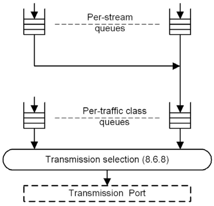
Figure 34-1—Queuing model for a Talker station
The Talker places frames into the queue associated with an individual stream based on the Tspec for that stream; i.e., during each class measurement interval, it can place up to MaxIntervalFrames data frames, each no longer than MaxFrameSize into that stream’s queue.
The queue associated with each individual stream uses the credit-based shaper algorithm, with the idleSlope set to the bandwidth requirement of the stream on that transmission Port, as the means of determining the rate at which data frames for that stream are placed in the outbound queue for the priority that the stream is using. The outbound queue for that priority, in turn, makes use of the credit-based shaper algorithm, with the idleSlope set to the sum of the idleSlope values for all streams using that priority on that transmission Port, as the means of determining the rate at which data frames for that stream are selected for transmission.
Transmission selection in a Talker operates in the same way as in a Bridge; from this point of view, a Talker can be thought of as if it is a single-port Bridge.
For streams that make use of SR class A or SR class B, it is a requirement that the rate at which frames for any given stream are selected for placement in its per-stream queue does not exceed the bandwidth reserved for the stream, measured over the class measurement interval for the SR class (125 μs for SR class A, 250 μs for SR class B.) For some combinations of stream bandwidth requirement and transmission Port data rate, this can place a limit on the frame size that can be used when transmitting stream data.
NOTE—The sole implication of the observation interval is its effect on frame size, because the shaper behavior itself is independent of the observation interval. The intent in limiting the observation interval is to limit frame size, as this is a major contribution to the latency experienced by a frame in transit through an audio/video bridging (AVB) network (see discussion in Annex L).
34.6.2 Listener behavior
The primary requirement for a listener station is that it is capable of buffering the amount of data that could be transmitted for a stream during a time period equivalent to the accumulated maximum jitter that could be experienced by stream data frames in transmission between Talker and Listener. From the point of view of the specification of the forwarding and queuing requirements for time-sensitive streams, it is assumed that the listener will assess the buffering required for a stream as part of the stream bandwidth reservation mechanisms employed by the implementation.
35 Stream Reservation Protocol (SRP)
SRP utilizes three signaling protocols, MMRP (10.9), MVRP (Clause 11) and MSRP (35.1), to establish stream reservations across a bridged network.
Within SRP the Multiple MAC Registration Protocol (MMRP) is optionally used to control the propagation of Talker registrations throughout the bridged network (35.2.4.3.1).
The Multiple VLAN Registration Protocol (MVRP) is used by end stations and Bridges to declare membership in a VLAN where a Stream is being sourced. This allows the Data Frame Priority (35.2.2.8.5(a)) to be propagated along the path from Talker to Listener(s) in tagged frames. MSRP will not allow Streams to be established across Bridge Ports that are members of the untagged set (8.8.10) for the related VID.
The Multiple Stream Registration Protocol (MSRP) is a signaling protocol that provides end stations with the ability to reserve network resources that will guarantee the transmission and reception of data streams across a network with the requested QoS. These end stations are referred to as Talkers (devices that produce data streams) and Listeners (devices that consume data streams).
Talkers declare attributes that define the stream characteristics so Bridges have the necessary information available when they need to allocate resources for a Stream. Listeners declare attributes that request reception of those same streams. Bridges along the path from Talker to Listener process, possibly adjust, and then forward these MSRP attribute declarations. Bridges associate Talker and Listener attributes via the StreamID present in each of those attributes, which result in changes to the extended filtering services and allocation of internal resources when streams are “brought up.”
In order to establish the SRP domain boundaries, Bridges exchange SR class characteristics with each other and with end stations via MSRP. Neighboring devices that have identical SR class characteristics are considered to be in the same SRP domain and streams may be established between those devices.
MSRP provides a limited error reporting capability that is utilized when a Listener’s request to receive a stream cannot be honored because of some resource constraint within the network.
MSRP also supports the concept of data stream importance. For example, an emergency announcement would be flagged with a more important “rank” than a stream providing background music. This ranking ability allows the Bridges to replace less important streams with more important streams without requiring intervention from the end stations.
There is a considerable body of experience in supplying data streams with guarantees for QoS parameters such as latency, latency variation, or bandwidth. In particular, routers and hosts use the Internet Protocol (IP) and the Resource Reservation Protocol (RSVP, IETF RFC 2205 and IETF RFC 2750) to achieve such guarantees. Supplying guarantees to a data stream requires the following two components:
a) A definition of the resources to be allocated and configured, by end stations and network nodes, for the support of a data stream; and
b) A protocol for end stations to signal to the network nodes their data streams’ requirements, for network nodes to distribute those requirements among each other, and for the network nodes to signal the success or failure of the attempt to reserve resources to support the guarantees.
RSVP supplies the signaling protocol for routers to support data streams in routed networks. This and the following clauses define a protocol to support data streams in bridged networks.
35.1 Multiple Stream Registration Protocol (MSRP)
MSRP supports the reservation of resources for streams, each destined for one or more Listeners, and each from a single source, across a bridged network. Transmitted data that conforms to a successful stream reservation will not be discarded by any Bridge due to congestion on a LAN. In order to propagate requests for reservations, MSRP defines an MRP application that provides the Stream resource registration service defined in 35.2.3. MSRP makes use of the MRP Attribute Declaration (MAD) function, which provides the common state machine descriptions defined for use in MRP-based applications. The MRP architecture, and MAD are defined in Clause 10. MSRP defines a new MRP Attribute Propagation (MAP) function, to provide an attribute propagation mechanism.
MSRP propagates registrations for stream reservations in a manner similar to the operation of MMRP (10.9) and MVRP (11.2), which are used for registering Group membership and individual MAC address information, and VLAN membership, respectively. Unlike MMRP and MVRP, however, the registered attributes can be combined, discarded, or otherwise altered, as they are propagated by the participating Bridges.
In order to make and keep QoS guarantees all devices in a bridged network must participate in the signaling and queuing operations required of Bridges. For example, this would include IEEE 802.11 wireless media access points and stations. Thus, MSRP provides a means for Bridges or end stations running MSRP to cooperate both with higher network layers, such as routers or hosts running RSVP, and with lower network layers, such as wireless media.
MSRP is also responsible for establishing the SRP domain boundary for a particular SR class. All systems that support a particular SR class are in the same SRP domain if they use the same priority. An SRP domain boundary exists for an SR class when neighboring devices use different priorities for the SR class.
Figure 35-1 illustrates the architecture of MSRP in the case of a two-Port Bridge and an end station.
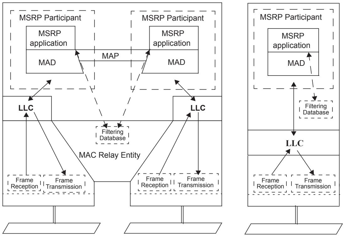
Figure 35-1—Operation of MSRP
35.1.1 MSRP and Shared Media
Classic shared media, such as IEEE 802.3 half-duplex Carrier Sense Multiple Access with Collision Detect (CSMA/CD), cannot provide latency or bandwidth guarantees, because their operation depends on random timers. Such media are therefore not supported by MSRP.
There are other shared media where one node on the medium exercises control over access to the medium by the other nodes. For example, an IEEE 802.11 wireless medium has a single Access Point (AP) that controls access by the AP and the stations attached to the wireless medium so that some guarantee of latency and bandwidth can be made, subject to frame loss caused by data corruption errors. Similarly, an IEEE 802.3 Ethernet Passive Optical Network has a single Optical Line Terminal (OLT) that controls access to the optical medium by itself and some number of Optical Network Units (ONUs).
Different kinds of shared media use different techniques to allocate opportunities to transmit, and these techniques can have various dependencies on frame sizes, station-to-station vs. station-to-head data paths, or other factors. Rather than introducing the complexities of every such medium into MSRP, this standard takes advantage of the presence of a controlling entity to map medium-specific characteristics to the capabilities of MSRP.
MSRP defines and requires the existence of a Designated MSRP Node (DMN) on any shared medium. This DMN provides the MSRP services for the shared medium and determines each station’s ability to receive the MSRPDUs transmitted by other stations on the medium. A Non-DMN Port shall be configured to only process the MSRPDUs transmitted by DMN Ports, and ignore the MSRPDUs transmitted by other Non-DMN Ports. Furthermore, the DMN has the absolute control of the resource allocation on the shared medium. Given these two facts, a DMN can effectively control which reservations are and are not successful on the medium it controls.
Annex C provides examples on various shared media.
35.1.2 Behavior of end stations
35.1.2.1 Talkers
To announce the Streams that can be supplied and their characteristics, Talkers use the MAD_Join.request primitive (10.2) to make the Talker Declarations (35.2.1.3). To indicate the Streams that are no longer supplied, Talkers use the MAD_Leave.request primitive (10.2) to withdraw their Talker Declarations.
Talker Declarations are propagated by MSRP such that the Listeners and Bridges are aware of the presence of Talkers and the Streams that are offered. Talker Declarations are also used to gather QoS information along their paths. Based on the gathered QoS information, Talker Declarations are classified as follows:
a) Talker Advertise: An advertisement for a Stream that has not encountered any bandwidth or other network contraints along the network path from the Talker. Listeners that request attachment to this Stream are likely to create a reservation with the described QoS. A Talker Advertise will continue to be declared as long as the resources continue to be available.
b) Talker Failed: An advertisement for a Stream that is not available to the Listener because of bandwidth contraints or other limitations somewhere along the path from the Talker.
Talkers respond to the registration and deregistration events of Listener Declarations (35.2.1.3), signalled by MAD as follows:
On receipt of a MAD_Join.indication for a Listener Declaration, the Talker first merges (35.2.4.4.3) the Listener Declarations that it has registered for the same Stream. Then the Talker examines the StreamID (35.2.2.8.2) and Declaration Type (35.2.1.3) of the merged Listener Declaration. If the merged Listener
Declaration is associated with a Stream that the Talker can supply, and the DeclarationType is either Ready or Ready Failed (i.e., one or more Listeners can receive the Stream), the Talker can start the transmission for this Stream immediately. If the merged Listener Declaration is an Asking Failed, the Talker shall stop the transmission for the Stream, if it is transmitting.
On receipt of a MAD_Leave.indication for a Listener Declaration, if the StreamID of the Declaration matches a Stream that the Talker is transmitting, then the Talker shall stop the transmission for this Stream, if it is transmitting.
35.1.2.2 Listeners
To indicate what Streams they want to receive, Listeners use the MAD_Join.request primitive (10.2) to make the Listener Declarations (35.2.1.3). To indicate the Streams that are no longer wanted, Listeners use the MAD_Leave.request primitive (10.2) to withdraw their Listener Declarations.
The Listener Declaration also conveys the results of the bandwidth and resource allocation along its path back to the Talker. Based on those results, Listener declarations are classified as follows:
a) Listener Ready: One or more Listeners are requesting attachment to the Stream. There is sufficient bandwidth and resources available along the path(s) back to the Talker for all Listeners to receive the Stream.
b) Listener Ready Failed: Two or more Listeners are requesting attachment to the Stream. At least one of those Listeners has sufficient bandwidth and resources along the path to receive the Stream, but one or more other Listeners are unable to receive the stream because of network bandwidth or resource allocation problems.
c) Listener Asking Failed: One or more Listeners are requesting attachment to the Stream. None of those Listeners are able to receive the Stream because of network bandwidth or resource allocation problems.
NOTE—The reader will notice that the Talker response to Ready and Ready Failed declarations is the same: the Talker can begin transmitting the Stream. Talkers might choose to pass the Ready Failed response to a higher layer protocol that could notify the user that the Stream is flowing, but not all Listeners are receiving it. It would be the responsibility of that higher layer to respond to this information as appropriate.
When there is a Talker Declaration registered on an interested Listener end station, the Listener shall create a Listener Declaration as follows:
If the Listener receives a Talker Advertise declaration, and the Listener is ready to receive the Stream, the Listener shall declare the following in the order specified:
d) An MVRP VLAN membership request for the vlan_identifier contained in the Talker Advertise DataFrameParameters [35.2.2.8.3(b)] so the neighboring Bridge will add the associated Bridge Port to the member set for the VLAN;
e) An MSRP Listener Ready declaration for the Stream.
If the Listener receives a Talker Failed declaration, and the Listener is ready to receive the Stream, the Listener shall issue a Listener Asking Failed declaration for the Stream.
There is no requirement for the order in which the Talker and Listener declarations are communicated. The Listener Declaration can be made before the Listener receives an associated Talker Declaration, in which case the Listener shall issue a Listener Asking Failed declaration.
35.1.3 Behavior of Bridges
MSRP-aware Bridges register and deregister Talker and Listener declarations on the Bridge Ports according to the procedures defined in MRP (Clause 10), and automatically generate deregistration of stale registrations. Any changes in the state of registration are processed by the MSRP Attribute Propagation (35.2.4) function, and disseminated in the network by making or withdrawing Talker and Listener declarations as defined in the Talker attribute propagation (35.2.4.3) and Listener attribute propagation (35.2.4.4).
In general, Talker declarations are propagated to all other Bridge Ports. There is a talkerPruning option (35.2.1.4(b)) that limits the scope of Talker declaration propagation. Listener declarations are only propagated to the Bridge Port with the associated Talker declaration (i.e., matching StreamID). If there is no associated Talker declaration registered on any Bridge Port then Listener declaration will not be propagated.
35.1.3.1 Blocked Declarations
For the purposes of MSRP Attribute Propagation (35.2.4), a Declaration is said to be “blocked” on a Bridge Port if the state of the spanning tree instance identified by the vlan_identifier in the DataFrameParameters (35.2.2.8.3) of the Declaration, on that Bridge Port, has any value other than Forwarding. In a station’s Participant, no Declaration is ever blocked.
35.1.4 SRP domains and status parameters
An SRP domain is a set of stations (end stations and/or Bridges), their Ports, and the attached individual LANs, that satisfy all of the following conditions for a given SR class:
a) Those stations that transmit streams all support the credit-based shaper algorithm, defined in 8.6.8, as the transmission selection method for the SR class.
b) The stations all support SRP as the means of creating bandwidth reservations for the SR class.
c) Those stations that transmit streams all associate the same priority value with the SR class.
d) Each Port in the set is either an SRP domain core port or an SRP domain boundary port.
e) Each SRP domain core Port in the set is connected, via an individual LAN that is part of the active topology, to an SRP domain core Port of another station in the set.
In Bridges that support the SRP, and for each SR class supported by the Bridge, an SRPdomainBoundaryPort parameter is associated with each Port of the Bridge.
Each SRPdomainBoundaryPort parameter has a Boolean value. The value of the SRPdomainBoundaryPort parameter for a given SR class is TRUE if the operation of SRP has determined that the Port is an SRP domain boundary port (3.193) for that SR class; otherwise, the Port either is an SRP domain core port (3.194) for that SR class or is not part of that SRP domain, and the SRPdomainBoundaryPort parameter value is FALSE.
35.2 Definition of the MSRP application
MSRP maintains two categories of variables. The first category is used internally by the application state machines. These are defined in detail in the subclauses that follow.
MSRP also defines another category of variables identified as MRP elements that are communicated in MSRPDUs between stations on a network. These protocol elements include the MRP frame addressing and other fields defined in the MRPDUs. The MSRP FirstValue fields, which are used to exchange the MSRP attributes, are also defined here.
35.2.1 Definition of internal state variables
The following variables and parameters are utilized by various state machines within MSRP:
a) Port Media Type (35.2.1.1);
b) Direction (35.2.1.2);
c) Declaration Type (35.2.1.3);
d) SRP parameters (35.2.1.4);
35.2.1.1 Port Media Type
MSRPDU processing on a port is handled differently depending on the type of medium the port is attached to. For example, the DMN on a shared medium port that receives MSRPDUs from one station shall update and retransmit those attributes so that all stations on that medium are updated appropriately. The possible values are as follows:
a) Access Control Port: Transmitter controls access to the medium on which it is sending, so either it is the DMN for a shared medium, or it is a port on a full-duplex point-to-point medium;
Non-DMN shared medium Port: Transmitter is attached to a shared medium, but does not control access to the medium.
35.2.1.2 Direction
The Direction field is derived from the MSRP AttributeType definitions (35.2.2.4). The Direction indicates whether this is a Talker or a Listener MSRP Declaration, and takes one of the following two values:
a) Talker: MSRP AttributeType definitions of type Talker Advertise Vector Attribute Type (35.2.2.4(a)) or Talker Failed Vector Attribute Type (35.2.2.4(b)). Set Direction to zero for Talker attributes.
b) Listener: MSRP AttributeType definitions of type Listener Vector Attribute Type (35.2.2.4(c)). Set Direction to one for Listener attributes.
35.2.1.3 Declaration Type
The Declaration Type field is derived from the MSRP AttributeType definitions (35.2.2.4) and the MSRP FourPackedEvents (35.2.2.7.2). The Declaration Type indicates the specific type of the Talker or Listener MSRP Declaration.
For a Talker, the value of the Declaration Type component is either
a) Advertise: MSRP AttributeType definitions of Talker Advertise Vector Attribute Type (35.2.2.4(a)).
b) Failed: MSRP AttributeType definitions of Talker Failed Vector Attribute Type (35.2.2.4(b)).
For a Listener, the value of the Declaration Type component is one of the following:
c) Asking Failed: MSRP AttributeType definitions of Listener Vector Attribute Type (35.2.2.4(c)) with MSRP FourPackedType equal to Asking Failed (35.2.2.7.2(b)).
d) Ready: MSRP AttributeType definitions of Listener Vector Attribute Type with MSRP FourPackedType equal to Ready (35.2.2.7.2(c)).
e) Ready Failed: MSRP AttributeType definitions of Listener Vector Attribute Type with MSRP FourPackedType equal to Ready Failed (35.2.2.7.2(d)).
35.2.1.4 SRP parameters
The following parameters are used by SRP:
a) portTcMaxLatency: The maximum per-port per-traffic class latency, expressed in nanoseconds, a frame may experience through the underlying MAC Service. There may be different latency numbers for different traffic classes on the same port.
b) talkerPruning: Enabling this parameter on the Bridge will limit the Talker declarations to ports that have the Streams destination_address (35.2.2.8.3(a)) in the MMRP MAC Address Registration Entries.
c) streamAge: A per-port per-stream 32-bit unsigned value used to represent the time, in seconds, since the control element for the associated port most recently became forwarding in the Dynamic Reservations Entries (8.8.7) corresponding to the stream’s destination_address. This value is used when determining which streams have been configured the longest. Streams with a numerically larger streamAge are considered to be configured earlier than other streams and therefore carry a higher implicit importance.
NOTE 1—A 32-bit unsigned value allows for expressing a streamAge of up to 136 years.
d) msrpEnabledStatus: MSRP shall have the ability to be enabled (true) or disabled (false) on a device. When MSRP is enabled on a device it shall cause a reset of all MSRP state machines on all ports. This affects the Applicant and Registrar state machines. The state of this parameter shall be persistent over power-up restart/reboot.
e) msrpPortEnabledStatus: MSRP shall have the ability to be enabled (true) or disabled (false) on the ports of a device. When MSRP is enabled or disabled on a port of a device it shall cause MAP to be rerun on all MSRP enabled ports so existing attributes can be propagated to the port just enabled. This affects the Applicant and Registrar state machines. The state of this parameter shall be persistent over power-up restart/reboot.
f) msrpMaxFanInPorts: The total number of ports on a Bridge that are allowed to establish reservations for inbound Streams. This number may be less than the total number of ports with msrpPortEnabledStatus set TRUE, which will result in lower maximum latency because of limits on the amount of possible interfering traffic. A value of zero (0) indicates no fan-in limit is being specified and calculations involving fan-in will only be limited by the number of MSRP enabled ports. Example calculations of delay associated with fan-in can be found in the paper “Calculating the Delay Added by Qav Stream Queue” [B4].
g) msrpLatencyMaxFrameSize: Calculation of the maximum latency through a Bridge is in-part related to the maximum size of an interfering frame. The maximum size is defined to be 2000 octets by default. This parameter allows a smaller or larger value to be used in the latency calculations for the particular Bridge implementation. msrpLatencyMaxFrameSize does not imply any type of policing of frame size, it is only used in the latency calculations.
h) SRPdomainBoundaryPort (35.1.4): A per-port, per-SR class, Boolean parameter that contains the value TRUE if the port is an SRP Domain Boundary Port; otherwise, it contains the value FALSE. The parameter for a given SR class and Port shall be set to TRUE if any of the following conditions are met:
1) The port is declaring an MSRP Domain attribute for that SR class, and the port has no MSRP Domain attribute registrations for that SR class, or;
2) The port is declaring an MSRP Domain attribute for that SR class, and the port has at least one MSRP Domain attribute registration for that SR class with a different priority, or;
3) One or more ports which support that SR class are declaring MSRP Domain attributes for that SR class, and this port does not support that SR class.
In all other cases the parameter shall be set to FALSE.
i) SR_PVID: The Stream Reservation Port VLAN Identifier is a per-port parameter that contains the default VID for Stream-related traffic. It shall contain a valid VID value (Table 9-2) and may be configured by management. If the value has not been explicitly configured, the SR_PVID shall assume the default SR_PVID defined in Table 9-2. This value is passed to the Talker via the SRclassVID (35.2.2.9.4) contained in the MSRP Domain attribute.
35.2.2 Definition of MRP elements
35.2.2.1 MSRP application address
The group MAC address used as the destination address for MRPDUs destined for MSRP Participants shall be the group MAC address for “Individual LAN Scope group address, Nearest Bridge group address” as specified in Table 8-1, Table 8-2 and Table 8-3 (C-VLAN, S-VLAN and TPMR component Reserved addresses, respectively).
NOTE—Using this address will guarantee that MSRPDUs are never forwarded by an 802.1 Bridge, although MSRP aware Bridges do propagate the MSRP attributes.
35.2.2.2 MSRP application EtherType
The EtherType used for MRPDUs destined for MSRP Participants shall be the MSRP EtherType identified in Table 10-2.
35.2.2.3 MSRP ProtocolVersion
The ProtocolVersion for the version of MSRP defined in this standard takes the hexadecimal value 0x00.
35.2.2.4 MSRP AttributeType definitions
MSRP defines four AttributeTypes (10.8.2.2) that are carried in MRP exchanges. The numeric values for the AttributeType are shown in Table 35-1 and their use is defined by the following list:
a) Talker Advertise Vector Attribute Type: Attributes identified by the Talker Advertise Vector Attribute Type are instances of VectorAttributes (10.8.1), used to identify a sequence of values of Talker advertisements for related Streams that have not been constrained by insufficient bandwidth or resources.
b) Talker Failed Vector Attribute Type: Attributes identified by the Talker Failed Vector Attribute Type are instances of VectorAttributes, used to identify a sequence of values of Talker advertisements for related Streams that have been constrained by insufficient bandwidth or resources.
c) Listener Vector Attribute Type: Attributes identified by the Listener Vector Attribute Type are instances of VectorAttributes, used to identify a sequence of values of Listener requests for related Streams regardless of bandwidth constraints. Listener Vector Attribute Types are subdivided into individual Declaration Types via the MSRP FourPackedEvents (35.2.2.7.2).
d) Domain Vector Attribute Type: Attributes identified by the Domain Vector Attribute Type are instances of VectorAttributes, used to identify a sequence of values that describe the characteristics of an SR class.
Table 35-1—AttributeType Values
<table><tr><td>AttributeType</td><td>Value</td></tr><tr><td>Talker Advertise Vector</td><td>1</td></tr><tr><td>Talker Failed Vector</td><td>2</td></tr><tr><td>Listener Vector</td><td>3</td></tr><tr><td>Domain Vector</td><td>4</td></tr></table>
35.2.2.5 MSRP AttributeLength definitions
The AttributeLength field (10.12.1.8) in instances of the Talker Advertise Vector Attribute Type shall be encoded in MRPDUs (10.8) as an unsigned binary number, equal to the value shown in Table 35-2 .
Table 35-2—AttributeLength Values
<table><tr><td>AttributeType</td><td>Value</td></tr><tr><td>Talker Advertise Vector</td><td>25 (0x19)</td></tr><tr><td>Talker Failed Vector</td><td>34 (0x22)</td></tr><tr><td>Listener Vector</td><td>8</td></tr><tr><td>Domain Vector</td><td>4</td></tr></table>
The AttributeLength field in instances of the Talker Failed Vector Attribute Type shall be encoded in MRPDUs as an unsigned binary number, equal to the value shown in Table 35-2.
The AttributeLength field in instances of the Listener Vector Attribute Type shall be encoded in MRPDUs as an unsigned binary number, equal to the value shown in Table 35-2.
The AttributeLength field in instances of the Domain Vector Attribute Type shall be encoded in MRPDUs as an unsigned binary number, equal to the value shown in Table 35-2.
35.2.2.6 MSRP AttributeListLength definitions
The AttributeListLength field (10.12.1.9) shall be encoded in MRPDUs (10.8) as an unsigned binary number, equal to the number of octets contained within the AttributeList. This field can be used when calculating the number of octets to skip to proceed to the next Message (or Message EndMark) in the MRPDU.
35.2.2.7 MSRP Vector definitions
35.2.2.7.1 MSRP ThreePackedEvents
The ThreePackedEvent vectors are encoded as defined in 10.8.2.10.1.
35.2.2.7.2 MSRP FourPackedEvents
MSRP FourPackedEvents are only used by the Listener Vector Attribute Type (35.2.2.4(c)). Within the FourPackedEvent, there are four possible values for the FourPackedType (10.8.2.10.2) as explained in the following list. The numeric values for the MSRP FourPackedEvents are shown in Table 35-3.
a) Ignore: The StreamID referenced by FirstValue+n is not defined in this MSRPDU. When using this FourPackedType, the AttributeEvent (10.8.2.10.1) value, encoded in the ThreePackedEvent, shall be set to zero on transmit and ignored on receive
b) Asking Failed: The StreamID referenced by FirstValue+n has a declaration type of Listener Asking Failed.
c) Ready: The StreamID referenced by FirstValue+n has a declaration type of Listener Ready.
d) Ready Failed: The StreamID referenced by FirstValue+n has a declaration of type Listener Ready Failed.
Table 35-3—FourPackedEvent Values
<table><tr><td>FourPackedType</td><td>Value</td></tr><tr><td>Ignore</td><td>0</td></tr><tr><td>Asking Failed</td><td>1</td></tr><tr><td>Ready</td><td>2</td></tr><tr><td>Ready Failed</td><td>3</td></tr></table>
NOTE—In terms of efficent use of octets within an MSRP packet, placing nineteen (19) Ignores between two Listener declarations uses less octets than using two VectorAttributes to declare the Listener attributes separately. A single Listener VectorAttribute takes 12 octets, two attributes would take 24 octets. Declaring 21 attributes (two valid attributes with 19 Ignores in between) takes 12 octets, plus 6 additional ThreePackedEvents, plus 5 additional FourPackedEvents for a total of 23 octets.
35.2.2.8 MSRP FirstValue definitions (stream reservations)
There are four attribute declarations defined for MSRP (35.2.2.4), three of which are related to stream reservations: Talker Advertise, Talker Failed, and Listener. The fourth attribute type, Domain, is used to discover the SRP domain, and is described in 35.2.2.9.
The Talker Advertise attribute contains all the characteristics that a Bridge needs in order to understand the resource requirements and importance of the referenced stream.
The Talker Failed attribute contains all the fields carried in the Talker Advertise Attribute, plus additional information regarding resource or bandwidth availability failures.
Listener attributes carry three subtypes: Ready, Ready Failed, and Asking Failed. These Listener subtypes are encoded in the FourPackedEvent (35.2.2.7.2).
FirstValue shall be incremented one or more times when NumberOfValues is greater than one. Incrementing FirstValue within MSRP is defined as follows:
a) Add 1 to Unique ID (35.2.2.8.2(b)), and
b) Add 1 to Stream destination_address (35.2.2.8.3(a))
The example shown in Table 35-4 illustrates the use of FirstValue and NumberOfValues within MSRP. This example shows four Streams (a, b, c and d) to be declared. In order to use the efficient packing techniques of MRP it would be preferable to assign these Streams sequential StreamIDs and destination_addresses as shown. Notice that StreamID yy-yy-yy-yy-yy-yy:00-04 is missing from this table (between Stream “c” and “d”). MSRP allows declaration of all four StreamIDs in a single VectorAttribute by setting NumberOfValues=5, with the StreamID = yy-yy-yy-yy-yy-yy:00-01 and a destination_address of xx-xx-xxxx-xx-25. Setting the fourth FourPackedEvent to Ignore (35.2.2.7.2(a)) notifies MSRP that the StreamID between “c” and “d” is not in use.
Table 35-4—MSRP FirstValue NumberOfValues example
<table><tr><td>Stream</td><td>StreamID</td><td>destination_address</td></tr><tr><td>a</td><td>yy-yy-yy-yy-yy-yy:00-01</td><td>xx-xx-xx-xx-xx-25</td></tr><tr><td>b</td><td>yy-yy-yy-yy-yy-yy:00-02</td><td>xx-xx-xx-xx-xx-26</td></tr><tr><td>c</td><td>yy-yy-yy-yy-yy-yy:00-03</td><td>xx-xx-xx-xx-xx-27</td></tr><tr><td>d</td><td>yy-yy-yy-yy-yy-yy:00-05</td><td>xx-xx-xx-xx-xx-29</td></tr></table>
The FirstValue field within MSRP comprises several components: StreamID (35.2.2.8.2), DataFrameParameters (35.2.2.8.3), TSpec (35.2.2.8.4), PriorityAndRank (35.2.2.8.5), Accumulated Latency (35.2.2.8.6), and FailureInformation (35.2.2.8.7). MSRP does not support changes in any of the FirstValue fields for an existing StreamID. If a Talker wishes to tear an old Stream down and bring a new Stream up, with a different FirstValue, utilizing the same StreamID, there must be at least two LeaveAllTime (Table 10-7) time periods between when the Talker removes the existing Stream registration and declares the new Stream. This guarantees that MRP has enough time to remove the current attribute from all devices in the network. If the new declaration were to occur too quickly the associated Streaming data could be corrupted because the FDB may allow the new Stream data to start flowing while the old Stream bandwidth constraints are still configured. When the Bridge detects this occuring it will fail the Talker Advertise with the appropriate FailureInformation (35.2.2.8.7). Talkers may tear a Stream down and bring the same Stream back up immediately, as long as the FirstValue has not changed.
35.2.2.8.1 Structure definition
The FirstValue for Talker Advertise, Talker Failed and Listener attributes in MSRPDUs exchanged according to the protocol specified in this subclause shall have the following structure:
a) The first eight octets contain the StreamID (35.2.2.8.2).
This is the end of the Listener attribute. If this is a Talker Advertise or Talker Failed attribute continue as follows:
b) Following the StreamID are eight octets containing the DataFrameParameters (35.2.2.8.3).
c) Following the DataFrameParameters are four octets containing the TSpec (35.2.2.8.4).
d) Following the TSpec is one octet containing the PriorityAndRank (35.2.2.8.5).
e) Following the PriorityAndRank are four octets containing the AccumulatedLatency (35.2.2.8.6).
This is the end of the Talker Advertise attribute. If this is a Talker Failed attribute continue as follows:
f) Following the AccumulatedLatency are nine octets containing the FailureInformation (35.2.2.8.7).
The following partial BNF production gives the formal description of the MSRPDU FirstValue structure for the Talker Advertise attribute:
FirstValue ::= StreamID, DataFrameParameters, TSpec, PriorityAndRank, AccumulatedLatency
The following partial BNF production gives the formal description of the MSRPDU FirstValue structure for the Talker Failed attribute:
FirstValue ::= StreamID, DataFrameParameters, TSpec, PriorityAndRank, AccumulatedLatency, FailureInformation
The following partial BNF production gives the formal description of the MSRPDU FirstValue structure for the Listener attribute:
FirstValue ::= StreamID
Figure 35-2 illustrates the structure of the MSRPDU FirstValue components. Each MSRP Attribute shall only use those structures as defined by the partial BNF productions described previously. The octet numbers shown represent the octet location within the FirstValue field.
<table><tr><td colspan="4">Octet #</td></tr><tr><td>1</td><td>7</td><td>8</td><td></td></tr><tr><td colspan="2">MAC Address</td><td>Unique ID</td><td>StreamID structure</td></tr><tr><td colspan="4">Octet #</td></tr><tr><td>9</td><td>15</td><td>16</td><td></td></tr><tr><td colspan="2">destination_address</td><td>vlan_identifier</td><td>DataFrameParameters structure</td></tr><tr><td colspan="4">Octet #</td></tr><tr><td>17</td><td>19</td><td>20</td><td></td></tr><tr><td>MaxFrameSize</td><td colspan="2">MaxIntervalFrames</td><td>TSpec structure</td></tr><tr><td colspan="4">Octet #</td></tr><tr><td colspan="4">21</td></tr><tr><td>Data Frame Priority (3 bits)</td><td>Rank (1 bit)</td><td>Reserved (4 bits)</td><td>PriorityAndRank structure</td></tr><tr><td colspan="4">Octet #</td></tr><tr><td>22</td><td>25</td><td></td><td></td></tr><tr><td colspan="2">Accumulated Latency</td><td></td><td>AccumulatedLatency structure</td></tr><tr><td colspan="4">Octet #</td></tr><tr><td>26</td><td></td><td>34</td><td></td></tr><tr><td colspan="2">Bridge ID</td><td>Failure Code</td><td>FailureInformation structure</td></tr></table>
Figure 35-2—Format of the components of the reservation FirstValue fields
35.2.2.8.2 StreamID
The 64-bit StreamID is used to match Talker registrations with their corresponding Listener registrations (35.2.4). The StreamID comprises the following two subcomponents:
a) An EUI-48 MAC Address associated with the System sourcing the stream to the bridged network. The entire range of EUI-48 addresses are acceptable.
b) A 16-bit unsigned integer value, Unique ID, used to distinguish among multiple streams sourced by the same System.
StreamIDs are unique across the entire bridged network and are generated by the system offering the stream, or possibly a device controlling that system. A system reserving resources for more than one stream in the same bridged network shall use a StreamID that is unique among all StreamIDs in that bridged network. The combination of these two subcomponents ensure that such an assignment is possible.
NOTE 1—The spanning tree protocol ensures that there can be at most one path from a Talker to its Listener(s). Multiple Declarations for the same StreamID can therefore occur briefly, during changes in the active topology of the bridged network.
NOTE 2—The MAC address component of the StreamID can, but does not necessarily, have the same value as the source_address parameter of any frame in the actual data stream.
35.2.2.8.3 DataFrameParameters
The DataFrameParameters component of the MSRP Attribute specifies the EISS parameters that are common to all frames belonging to the data stream for which this MAD is reserving resources. This information is used by Bridges to create Dynamic Reservation Entries (8.8.7). The parameters are as follows:
a) The destination_address; and
b) The vlan_identifier.
The destination_address specifies the destination MAC address of the streaming data packets. Only one Talker is allowed per destination_address. MSRP does not describe the actual streaming data, only the bandwidth associated with that stream.
The use of destination_address for both a Stream and “best effort” traffic (34.5) is outside the scope of SRP. SRP only supports destination_addresses that are multicast or locally administered addresses.
NOTE—MSRP enforces reserved bandwidth guarantees by filtering Stream destination addresses (35.2.4.4.2) for Streams that do not have a reservation. This blocks all traffic to that destination address. If that destination address was also being used for “best effort” traffic that device would no longer be reachable.
Systems that are not VLAN aware shall use the value SRclassVID (35.2.2.9.4) for the vlan_identifier in the DataFrameParameters. VLAN aware systems may use any valid VID (1 through 4094).
35.2.2.8.4 TSpec
The 32-bit TSpec component is the TSpec associated with a Stream. It consists of the following two elements (which are encoded as described in 10.8.1.1):
a) MaxFrameSize: The 16-bit unsigned MaxFrameSize component is used to allocate resources and adjust queue selection parameters in order to supply the QoS requested by an MSRP Talker Declaration. It represents the maximum frame size that the Talker will produce, excluding any overhead for media-specific framing (e.g., preamble, IEEE 802.3 header, Priority/VID tag, CRC, interframe gap). As the Talker or Bridge determines the amount of bandwidth to reserve on the egress port it will calculate the media-specific framing overhead on that port and add it to the number specified in the MaxFrameSize field.
b) MaxIntervalFrames: The 16-bit unsigned MaxIntervalFrames component is used to allocate resources and adjust queue selection parameters in order to supply the QoS requested by an MSRP Talker Declaration. It represents the maximum number of frames that the Talker may transmit in one “class measurement interval” (34.4).
NOTE—Consider the example of a Class A 48kHz stereo audio stream encapsulated in an ethernet frame (see IEEE Std 1722™ [B13]). The audio data within the frame would contain two sets of six 32-bit samples, plus a 32-octet header, for a total of 80 octets per frame sent once every class measurement interval (34.4). Therefore, MaxFrameSize=80, and MaxIntervalFrames=1. An IEEE 802.3 port on a Bridge would also add 42 octets of mediaspecific framing overhead (8-octet preamble, 14-octet IEEE 802.3 header, 4-octet IEEE 802.1Q priority/VID Tag, 4-octet CRC, 12-octet IFG). When the Bridge calculates the amount of bandwidth to reserve it would combine 42 octets of media-specific framing overhead with the MaxFrameSize of 80 octets, to arrive at a total frame size of 122 octets per class measurement interval. This represents a total bandwidth of approximately 7.7Mbit/s (122 octets * 8 bits/octet * 8000 frames/s).
Table 35-5 contains some examples of various forms of audio and video Streams with their associated TSpec components.
Table 35-5—TSpec components examples
<table><tr><td>Source</td><td>Raw Bit Rate</td><td>Media Specific Framing Overhead</td><td>TSpec MaxFrameSize</td><td>TSpec MaxIntervalFrames</td></tr><tr><td>48kHz stereo audio stream (32-bit samples) Class A (IEEE Std 1722 [B13])</td><td>~3 Mbit/sec</td><td>~4.7 Mbit/sec</td><td>80</td><td>1(8,000 frames/sec)</td></tr><tr><td>96kHz stereo audio stream (32-bit samples) Class A (IEEE Std 1722 [B13])</td><td>~6 Mbit/sec</td><td>~4.7 Mbit/sec</td><td>128</td><td>1(8,000 frames/sec)</td></tr><tr><td>MPEG2-TS video Class B (IEEE Std 1722 [B13])</td><td>~24 MBit/sec</td><td>~2.5 Mbit/sec</td><td>786</td><td>1(4,000 frames/sec)<eq>^{1}</eq></td></tr><tr><td>SD SDI (Level C) uncompressed Class A (SMPTE 259M-2008 [B51])</td><td>270 Mbit/sec</td><td>~15 Mbit/sec</td><td>1442</td><td>3(24,000 frames/sec)</td></tr><tr><td>SD SDI (Level D) uncompressed Class A (SMPTE 259M-2008 [B51])</td><td>360 Mbit/sec</td><td>~20 Mbit/sec</td><td>1442</td><td>4(32,000 frames/sec)</td></tr><tr><td>HD SDI 1080i uncompressed Class A (SMPTE 292M-2008 [B52])</td><td>1.485 Gbit/sec</td><td>~80 Mbit/sec</td><td>1486</td><td>16(128,000 frames/sec)</td></tr><tr><td>HD SDI 1080p uncompressed Class A (SMPTE 424M-2008 [B53])</td><td>2.97 Gbit/sec</td><td>~160 Mbit/sec</td><td>1486</td><td>32(256,000 frames/sec)</td></tr></table>
1The MPEG-2 TS entry in this table (third row) is shown as Class B traffic which runs at a default frame rate of 250 μs/frame, or 4000 frames/sec. Class A traffic runs at a default rate of 8000 frames/sec.
35.2.2.8.5 PriorityAndRank
a) Data Frame Priority: The 3-bit Data Frame Priority component specifies the priority value used to generate the Priority Code Point the referenced data streams will be tagged with. It indicates the priority EISS or ISS parameter that will be used in all frames belonging to the data stream for which this MAD is reserving resources. This parameter determines which queue the frame is placed into on an output Bridge Port. In accordance with 10.8.1.1 these three bits are in the most significant positions (8, 7 and 6). The priority specified here is associated with the SR Classes as described in 34.5.
b) Rank: The single-bit Rank component is used by systems to decide which streams can and cannot be served, when the MSRP registrations exceed the capacity of a Port to carry the corresponding data streams. If a Bridge becomes oversubscribed (e.g., network reconfiguration, IEEE 802.11 bandwidth reduction) the Rank will also be used to help determine which Stream or Streams can be dropped. A lower numeric value is more important than a higher numeric value. In accordance with 10.8.1.1 this bit is in position 5.
For streams that carry emergency data such as North America 911 emergency services telephone calls, or fire safety announcements, the Rank shall be 0. Nonemergency traffic shall set this bit to a 1.
NOTE—It is expected that higher layer applications and protocols can use the Rank to indicate the relative importance of streams based on user preferences expressed by means beyond the scope of this standard. The values and defaults provided by this Standard are sufficient to order streams on a first-come-first-served basis, with special priority provided for emergency services.
c) Reserved: This 4-bit field shall be zero filled on transmit and ignored on receive. In accordance with 10.8.1.1 these four bits are in the least significant positions (4, 3, 2 and 1).
35.2.2.8.6 Accumulated Latency
The 32-bit unsigned Accumulated Latency component is used to determine the worst-case latency that a Stream can encounter in its path from the Talker to a given Listener. The latency reported here is not intended to increase during the life of the reservation. If some event occurs that would increase the latency beyond the original guarantee, MSRP will change the Talker Advertise to a Talker Failed and report Failure Code=7 (Table 35-6).
NOTE 1—An example of how latency could increase is if the speed of the underlying media where to decrease, such as one might see on a wireless link.
The initial value sent by the Talker is set to portTcMaxLatency: plus any amounts specified in the REGISTER_STREAM.request, and its value is increased by each Bridge as the Talker Declaration propagates through the network.
The portTcMaxLatency: per hop is equal to the sum of
a) (equal or higher priority traffic) the time required to empty the queue in which frames of that priority are placed, if that queue and all higher priority queues are full;
b) (lower priority traffic) the time required to transfer one lower priority frame of maximum size that could have just started transmitting as the current priority frame was queued up;
c) (internal processing) the worst-case time required by the Bridge to transfer a received frame from the input port to the output queue; and
d) (wire propagation time) the time required for the first bit of the frame to propagate from the output port to the receiving device;
e) (media access delay) the time required to wait for the media to become available for transmission.
For item a) the total number of ports with msrpPortEnabledStatus set TRUE, and the msrpMaxFanInPorts will effect these calculations40.
For item a) and item b) the maximum size of the interfering traffic is limited to msrpLatencyMaxFrameSize octets.
For item d, the propagation time, in the absence of better information, a value of 500 ns shall be used.
NOTE 2—This implies that no type of frame flow control can be used on the associated data stream packets.
The Listener can use this information to decide if the Latency is too large for acceptable presentation of the stream. The Accumulated Latency component is in units of nanoseconds.
35.2.2.8.7 FailureInformation
At the point when a Talker Advertise Declaration is transformed into a Talker Failed Declaration, the Bridge making the transformation adds information that indicates, to the Listeners registering the Talker Failed Declaration, the cause of the failure, and the identity of the Bridge at which the failure occurred. The subcomponents of the FailureInformation include
a) The Bridge ID (13.26.2) of the Bridge that changed the Declaration Type from Advertise to Failed.
The Reservation Failure Code, which is represented by a single octet containing the value shown in Table 35-6.
Table 35-6—Reservation Failure Codes
<table><tr><td>Failure Code</td><td>Description of cause</td></tr><tr><td>1</td><td>Insufficient bandwidth</td></tr><tr><td>2</td><td>Insufficient Bridge resources</td></tr><tr><td>3</td><td>Insufficient bandwidth for traffic class.</td></tr><tr><td>4</td><td>StreamID in use by another Talker</td></tr><tr><td>5</td><td>Stream destination_address already in use</td></tr><tr><td>6</td><td>Stream preempted by higher rank</td></tr><tr><td>7</td><td>Reported latency has changed</td></tr><tr><td>8</td><td>Egress port is not AVB capable<eq>^{1}</eq></td></tr><tr><td>9</td><td>Use a different destination_address (i.e., MAC DA hash table full)</td></tr><tr><td>10</td><td>Out of MSRP resources</td></tr><tr><td>11</td><td>Out of MMRP resources</td></tr><tr><td>12</td><td>Cannot store destination_address (i.e., Bridge is out of MAC DA resources)</td></tr><tr><td>13</td><td>Requested priority is not an SR Class (3.231) priority</td></tr><tr><td>14</td><td>MaxFrameSize (35.2.2.8.4(a)) is too large for media</td></tr><tr><td>15</td><td>msrpMaxFanInPorts (35.2.1.4(f)) limit has been reached</td></tr><tr><td>16</td><td>Changes in FirstValue for a registered StreamID.</td></tr><tr><td>17</td><td>VLAN is blocked on this egress port (Registration Forbidden)<eq>^{2}</eq></td></tr><tr><td>18</td><td>VLAN tagging is disabled on this egress port (untagged set)</td></tr><tr><td>19</td><td>SR class priority mismatch</td></tr></table>
1A device could choose to use the asCapable variable from IEEE Std 802.1AS™-2011 [B7], 10.2.4.1, to help determine if its neighboring device is AVB capable. If the asCapable variable is FALSE for a particular port, then the neighboring device is not a time-aware system and therefore not AVB capable.
2This Failure Code is never declared in a Talker Failed message since Talker attributes are not propagated on egress ports that have the associated VLAN blocked. The Bridge can still be queried by other means to learn why the Talker attribute was not declared.
35.2.2.9 MSRP FirstValue definitions (Domain discovery)
The Domain attribute contains all the information that a Bridge Port needs in order to determine the location of the SRP domain boundary (35.2.1.4(h)).
FirstValue shall be incremented one or more times when NumberOfValues is greater than one. Incrementing FirstValue for the MSRP Domain attribute is defined as follows:
a) Add 1 to SRclassID (35.2.2.9.2), and
b) Add 1 to SRclassPriority (35.2.2.9.3)
The choice of encoding and incrementing with this rule means that if one class (e.g., class B) is supported, then the FirstValue will be {5,2,VID} (class B, priority 2, and a VID) and the NumberOfValues field will be set to 1. If class A and class B are supported, with the default values, the FirstValue will again be {5,2,VID}, but the NumberOfValues fields will be set to 2. Applying the above incrementing rule to {5,2,VID} generates the value {6,3,VID}, i.e., class A, priority 3, and a VID, which is needed for the default case.
35.2.2.9.1 Structure definition
The FirstValue for the Domain attribute in MSRPDUs exchanged according to the protocol specified in this subclause shall have the following structure:
a) The first octet contains the SRclassID (35.2.2.9.2).
b) Following the SRclassID is an octet containing the SRclassPriority (35.2.2.9.3).
c) Following the SRclassPriority are two octets containing the SRclassVID (35.2.2.9.4).
The following BNF production gives the formal description of the MSRPDU FirstValue structure for the Domain attribute:
FirstValue ::= SRclassID, SRclassPriority, SRclassVID
Figure 35-3 illustrates the structure of the MSRPDU FirstValue components for the Domain attribute.
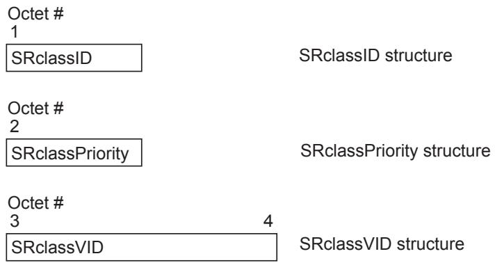
Figure 35-3—Format of the components of the Domain FirstValue
35.2.2.9.2 SRclassID
SRclassID is a numeric representation of the SR classes that are supported by a particluar Bridge Port. The mapping for the first two SR classes is shown in Table 35-7.
Table 35-7—SR class ID
<table><tr><td>SR class</td><td>SR class ID</td></tr><tr><td>A</td><td>6</td></tr><tr><td>B</td><td>5</td></tr></table>
35.2.2.9.3 SRclassPriority
This fields holds the Data Frame Priority (35.2.2.8.5(a)) value that will be used for streams that belong to the associated SR class. Whenever an end station's MAC_Operational (IEEE Std 802.1AC) transitions to TRUE, its SRclassPriority shall be set to the default SR class priority (Table 6-5) until an SRclassPriority declaration is received from a neighboring device, at which time it shall be set to the declared value.
NOTE—This allows two end stations that are connected back-to-back to share streams, while also providing an end station the flexibility to change to the SRclassPriority of a attached network.
35.2.2.9.4 SRclassVID
This field contains the SR_PVID (35.2.1.4(i)) that the associated streams will be tagged with by the Talker. Whenever an end station's MAC_Operational (IEEE Std 802.1AC) transitions to TRUE, its SRclassVID shall be set to the default SR_PVID (Table 9-2) until an SRclassVID declaration is received from a neighboring device, at which time it shall be set to the declared value.
NOTE—This allows two end stations that are connected back-to-back to share streams, while also providing an end station the flexibility to change to the SRclassVID of a attached network.
35.2.3 Provision and support of Stream registration service
35.2.3.1 Initiating MSRP registration and deregistration
MSRP utilizes the following five declaration types (35.2.1.3) to communicate: Talker Advertise, Talker Failed, Listener Ready, Listener Ready Failed and Listener Asking Failed.
An SR Station behaving as a Talker will send a Talker Advertise declaration to inform the network about the characteristics (35.2.2.8) of the Stream it can provide. Bridges register this declaration, update some of the information contained within the Talker declaration, and forward it out the nonblocked (35.1.3.1) ports on the Bridge. If talkerPruning is enabled and the Bridge has the Stream’s destination_address registered on one or more ports (via MMRP) it shall only forward the declarations out those ports. Eventually the Talker declaration will be registered by other SR stations.
If talkerPruning is enabled and the Stream’s destination_address is not registered on any ports the Talker declaration shall not be forwarded.
An SR Station behaving as a Listener will receive the Talker Advertise declaration and register it. If the Listener is interested in receiving that Stream it will send a Listener Ready declaration back toward the Talker. The Bridge’s MSRP MAP function will use the StreamID (35.2.2.8.2) to associate the Listener Ready with the Talker Advertise and forward the Listener Ready declaration only on the port that registered the Talker Advertise. This is referred to as Listener Pruning since the declarations are not forwarded out any other ports. The Bridge will also reserve the required bandwidth and configure its queues and the FDB.
If any Bridge along the path from Talker to Listener does not have sufficient bandwidth or resources available its MSRP MAP function will change the Talker Advertise declaration to a Talker Failed declaration before forwarding it. Similarly a Listener Ready declaration will be changed to a Listener Asking Failed declaration if there is not sufficient bandwidth or resources available. This way both the Talker and Listener will know whether the reservation was successful.
In the case where there is a Talker attribute and Listener attribute(s) registered within a Bridge for a StreamID and a MAD_Leave.request is received for the Talker attribute, the Bridge shall act as a proxy for the Listener(s) and automatically generate a MAD_Leave.request back toward the Talker for those Listener attributes. This is a special case of the behavior described in 35.2.4.4.1.
Finally, there is the Listener Ready Failed declaration. This is used when there are two or more Listeners for a Stream. To simplify the explanation assume there are only two Listeners and one has sufficient bandwidth back to the Talker (signified by a Listener Ready), and the other does not (signified by a Listener Asking Failed). At some point in the network topology there will be a single Bridge that will receive the Listener Ready on one port from the first Listener and the Listener Asking Failed on another port from the second Listener. That Bridge’s MSRP MAP function will merge (35.2.4.4.3) those two declarations into a single Listener Ready Failed declaration that will be forwarded to the Talker. When the Talker receives the Listener Ready Failed it will know there are one or more Listeners that want the Stream and can receive it, and there are one or more Listeners that want the Stream but have insufficient bandwidth or resources somewhere along the path to receive it. The Talker may still send the Stream, but it will realize that not all Listeners are going to receive it.
MSRP provides a set of Service Primitives that control the declarations of the attributes defined previously. The primitives associated with the Talker application entities are summarized in Table 35-8. Listener application entities have a corresponding set of primitives summarized in Table 35-9.
Table 35-8—Summary of Talker primitives
<table><tr><td>Name</td><td>Request</td><td>Indication</td></tr><tr><td>REGISTER_STREAM</td><td>35.2.3.1.1</td><td>—</td></tr><tr><td>DEREGISTER_STREAM</td><td>35.2.3.1.3</td><td>—</td></tr><tr><td>REGISTER_ATTACH</td><td>—</td><td>35.2.3.1.6</td></tr><tr><td>DEREGISTER_ATTACH</td><td>—</td><td>35.2.3.1.8</td></tr></table>
Table 35-9—Summary of Listener primitives
<table><tr><td>Name</td><td>Request</td><td>Indication</td></tr><tr><td>REGISTER_STREAM</td><td>—</td><td>35.2.3.1.2</td></tr><tr><td>DEREGISTER_STREAM</td><td>—</td><td>35.2.3.1.4</td></tr><tr><td>REGISTER_ATTACH</td><td>35.2.3.1.5</td><td>—</td></tr><tr><td>DEREGISTER_ATTACH</td><td>35.2.3.1.7</td><td>—</td></tr></table>
35.2.3.1.1 REGISTER_STREAM.request
A Talker application entity shall issue a REGISTER_STREAM.request to the MSRP Participant to initiate the advertisement of an available Stream.
A Talker may choose to enter a nonzero value in the Accumulated Latency that indicates the amount of latency in nanoseconds that a Stream will encounter before being passed to the MAC Service interface.
On receipt of a REGISTER_STREAM.request the MSRP Participant shall issue a MAD_Join.request service primitive (10.2, 10.3). The attribute_type (10.2) parameter of the request shall carry the value of Talker Advertise Vector Attribute Type (35.2.2.4(a)) or Talker Failed Vector Attribute Type (35.2.2.4(b)), depending on the Declaration Type. The attribute_value (10.2) parameter shall carry the values from the REGISTER_STREAM.request primitive.
REGISTER_STREAM.request (
StreamID,
Declaration Type,
DataFrameParameters,
TSpec,
Data Frame Priority,
Rank,
Accumulated Latency,
FailureInformation
)
35.2.3.1.2 REGISTER_STREAM.indication
A REGISTER_STREAM.indication notifies the Listener application entity that the referenced Stream is being advertised by a Talker somewhere on the attached network.
On receipt of a MAD_Join.indication service primitive (10.2, 10.3) with an attribute_type of Talker Advertise Vector Attribute Type or Talker Failed Vector Attribute Type the MSRP application shall issue a REGISTER_STREAM.indication to the Listener application entity. The REGISTER_STREAM.indication shall carry the values from the attribute_value parameter.
REGISTER_STREAM.indication (
StreamID,
Declaration Type,
DataFrameParameters,
TSpec,
Data Frame Priority,
Rank,
Accumulated Latency,
FailureInformation
)
35.2.3.1.3 DEREGISTER_STREAM.request
A Talker application entity shall issue a DEREGISTER_STREAM.request to the MSRP Participant to remove the Talker’s advertisement declaration, and thus remove the advertisement of a Stream, from the network.
On receipt of a DEREGISTER_STREAM.request the MSRP Participant shall issue a MAD_Leave.request service primitive (10.2, 10.3) with the attribute_type set to the Declaration Type currently associated with the StreamID. The attribute_value parameter shall carry the StreamID and other values that were in the associated REGISTER_STREAM.request primitive.
DEREGISTER_STREAM.request (
StreamID
)
35.2.3.1.4 DEREGISTER_STREAM.indication
A DEREGISTER_STREAM.indication notifies the Listener application entity that the referenced Stream is no longer being advertised by a Talker.
On receipt of a MAD_Leave.indication service primitive (10.2, 10.3) with an attribute_type of Talker Advertise Vector Attribute Type or Talker Failed Vector Attribute Type the MSRP application shall issue a DEREGISTER_STREAM.indication to the Listener application entity.
DEREGISTER_STREAM.indication (StreamID)
35.2.3.1.5 REGISTER_ATTACH.request
A Listener application entity shall issue a REGISTER_ATTACH.request to the MSRP Participant to request attachment to the referenced Stream.
On receipt of a REGISTER_ATTACH.request the MSRP Participant shall issue a MAD_Join.request service primitive (10.2, 10.3). The attribute_type parameter of the request shall carry the value of Listener Vector Attribute Type (35.2.2.4(c)). The attribute_value shall contain the StreamID and the Declaration Type.
REGISTER_ATTACH.request (
StreamID,
Declaration Type
)
35.2.3.1.6 REGISTER_ATTACH.indication
A REGISTER_ATTACH.indication notifies the Talker application entity that the referenced Stream is being requested by one or more Listeners.
On receipt of a MAD_Join.indication service primitive (10.2, 10.3) with an attribute_type of Listener Vector Attribute Type the MSRP application shall issue a REGISTER_ATTACH.indication to the Talker application entity. The REGISTER_ATTACH.indication shall carry the values from the attribute_value parameter.
REGISTER_ATTACH.indication (
StreamID,
Declaration Type
)
35.2.3.1.7 DEREGISTER_ATTACH.request
A Listener application entity shall issue a DEREGISTER_ATTACH.request to the MSRP Participant to remove the request to attach to the referenced Stream.
On receipt of a DEREGISTER_ATTACH.request the MSRP Participant shall issue a MAD_Leave.request service primitive (10.2, 10.3) with the attribute_type set to the Listener Vector Attribute Type. The attribute_value parameter shall carry the StreamID and the Declaration Type currently associated with the StreamID.
DEREGISTER_ATTACH.request (
StreamID
)
35.2.3.1.8 DEREGISTER_ATTACH.indication
A DEREGISTER_ATTACH.indication notifies the Talker application entity that the referenced Stream is no longer being requested by any Listeners.
On receipt of a MAD_Leave.indication service primitive (10.2, 10.3) with an attribute_type of Listener Vector Attribute Type the MSRP application shall issue a DEREGISTER_ATTACH.indication to the Talker application entity. The DEREGISTER_ATTACH.indication shall contain the StreamID.
DEREGISTER_ATTACH.indication (StreamID)
35.2.4 MSRP Attribute Propagation
There is no MSRP MAP function for Domain attributes. MSRP simply declares the characteristics of the SR classes that are supported on the Bridge Port regardless of what has been learned from Domain registrations on other Bridge Ports.
This clause describes
a) Rules for combining and propagating Listener attributes toward the associated Talker,
b) How MSRP adjusts the Talker and Listener attributes before propagating them.
Unless stated otherwise, Talker and Listener attributes are propagated as described in 10.3.
In principle, the MAP performs MSRP Attribute Propagation when any of the following conditions occur:
c) A MAD_Join.indication adds a new attribute to MAD (with the new parameter, 10.2, set to TRUE);
d) A MAD_Leave.indication is issued by the MAD;
e) An internal application declaration or withdrawal is made in a station;
f) When the bandwidth of the underlying media changes (see bandwidthAvailabilityChanged notification in 34.3.2);
g) A port becomes an SRP domain core port (3.230);
h) If talkerPruning (35.2.4.3.1) is enabled and there is a change in the MMRP (10.9) attributes registered on a port.
The MSRP MAP function is responsible for adjusting and propagating Talker and Listener attributes throughout the bridged network. It also updates the Dynamic Reservation Entries (8.8.7) to specify which Streams shall be filtered and which shall be forwarded, along with updating the associated streamAge [35.2.1.4(c)]. The bandwidth associated with those Streams is reported to the queuing algorithms via the operIdleSlope(N) parameter [34.3(d)] on a per-port per-traffic class basis.
Streams of higher importance are given available bandwidth before streams of lower importance.
If insufficient bandwidth or resources are available the streams destination_address will be filtered and the failure will be noted in the Talker and Listener attributes declared from that Bridge.
A port shall only forward MSRP declarations for SR classes it supports. This will eliminate unnecessary priority remapping for traffic related to unsupported SR classes.
The following subclauses describe what the MSRP MAP function shall accomplish.
35.2.4.1 Stream importance
MSRP utilizes the stream Rank (35.2.2.8.5(b)) to decide which stream is more important than another.
In the case where two streams have the same Rank, the streamAge will be compared. If the Ranks are identical and the streamAges are identical the StreamIDs (35.2.2.8.2) will be compared and the numerically lower StreamID is considered to be more important.
35.2.4.2 Stream bandwidth calculations
As referenced in Table 35-5, the bandwidth requirements of a Stream include more than just the amount specified in the REGISTER_STREAM.request (35.2.3.1.1). SRP shall add the perFrameOverhead (34.4) associated with the media attached to the port.
If this port is on a Shared Media (35.1.1) the bandwidth requirements may need to be further increased. For example, a Stream transmitted from one station to another may have to be sent across the media twice. One time from the Talker station to the DMN, and a second time from the DMN to the Listener station. In this case the bandwidth requirements would need to be doubled.
The totalFrameSize for a stream on an outbound Port is therefore the sum of the following three amounts (doubled if each frame is transmitted on the media twice):
a) MaxFrameSize (35.2.2.8.4(a));
b) perFrameOverhead (34.4) associated with the media attached to the port;
c) one (1) additional octet to account for slight differences (up to 200 ppm) in the class measurement interval between neighboring devices.
Multiply totalFrameSize by MaxIntervalFrames (35.2.2.8.4(b)) to arrive at the associated bandwidth (in bits per second), which is then used to update operIdleSlope(N) as shown in Table 35-13.
Streams that are in the Listener Ready or Listener Ready Failed state reduce the amount of bandwidth available to other Streams. Streams that have no Listeners, or the Listeners are in the Asking Failed state, do not reduce available bandwidth for other Streams since the Stream data will not be flowing through this outbound port. These details are considered when calculating how many Streams can flow through a particular port. The total amount of bandwidth available to a particular traffic class on a port is represented by deltaBandwidth(N) [34.3(b1)]. Subclause 34.3.1 describes the relationship of available bandwidth between traffic classes.
35.2.4.3 Talker attribute propagation
Table 35-10 describes the propagation of Talker attributes for a StreamID from one port of a Bridge to another. If no Talker attributes are registered for a StreamID then no Talker attributes for that StreamID will be declared on any other port of the Bridge. If a Talker Failed is registered then it will be propagated as a Talker Failed out all other nonblocked (35.1.3.1) ports on the Bridge.
Talker Advertise registrations require further processing by the MAP function. MAP will analyze available bandwidth and other factors to determine if the outbound port has enough resources available to support the Stream. MAP will also verify msrpMaxFanInPorts, if nonzero, will not be exceeded. If there are sufficient resources and bandwidth available MAP will declare a Talker Advertise. Otherwise, MAP will declare a Talker Failed on the outbound port and add appropriate FailureInformation.
Table 35-10—Talker attribute propagation per port
<table><tr><td rowspan="2" colspan="2"></td><td colspan="3">Talker</td></tr><tr><td>(none)</td><td>Advertise</td><td>Failed</td></tr><tr><td rowspan="4">Listener</td><td>(none)</td><td>(none)</td><td>Talker Advertise or Talker Failed</td><td>Talker Failed</td></tr><tr><td>Ready</td><td>(none)</td><td>Talker Advertise or Talker Failed</td><td>Talker Failed</td></tr><tr><td>Ready Failed</td><td>(none)</td><td>Talker Advertise or Talker Failed</td><td>Talker Failed</td></tr><tr><td>Asking Failed</td><td>(none)</td><td>Talker Advertise or Talker Failed</td><td>Talker Failed</td></tr></table>
35.2.4.3.1 Talker Pruning
By default Talker declarations are sent out all nonblocked ports. If talkerPruning is enabled and the destination_address (35.2.2.8.3(a)) of the Stream is found in the MAC Address Registration Entries (8.8.4) for the port, the declaration shall be forwarded. If the destination_address is not found the declaration shall be blocked and no Talker declaration of any type shall be forwarded.
35.2.4.4 Listener attribute propagation
Listener Attributes, unlike Talker Attributes, can be merged (35.2.4.4.3) from several Listeners on different ports into a single Listener declaration. There are two steps involved:
a) Processing of incoming Listener attribute registration on a port based upon the status of the associated Talker attribute registration,
b) Merging all the individual ports Listener attributes gathered in step 1, above, into a single Listener attribute to be declared on the nonblocked (35.1.3.1) outbound port which has the associated Talker registration. If no Talker attribute is registered within the Bridge for the StreamID associated with the Listener, the Listener attribute will not be propagated.
35.2.4.4.1 Incoming Listener attribute processing
Table 35-11 describes how Listener attributes are propagated from the incoming ports.
Table 35-11—Incoming Listener attribute propagation per port
<table><tr><td rowspan="2" colspan="2"></td><td colspan="3">Talker</td></tr><tr><td>(none)</td><td>Advertise</td><td>Failed</td></tr><tr><td rowspan="4">Listener</td><td>(none)</td><td>(none)</td><td>(none)</td><td>(none)</td></tr><tr><td>Ready</td><td>(none)</td><td>Listener Ready</td><td>Listener Asking Failed</td></tr><tr><td>Ready Failed</td><td>(none)</td><td>Listener Ready Failed</td><td>Listener Asking Failed</td></tr><tr><td>Asking Failed</td><td>(none)</td><td>Listener Asking Failed</td><td>Listener Asking Failed</td></tr></table>
If no Listener attributes are registered on a particular port then no Listener attribute will be propagated to the Listener attribute merging (35.2.4.4.3) from that port.
If a Listener Asking Failed is registered on a port then it will be propagated as a Listener Asking Failed and merged with other Listener Attributes from other ports.
If no Talker attributes are associated with the Listener attribute, the Listener attribute will not be propagated.
If a Talker Failed is registered on another port for the associated Listener Ready or Listener Ready Failed then a Listener Asking Failed will be propagated and merged with other Listener attributes from other ports.
If a Talker Advertise is registered on another port for the StreamID associated with a Listener Ready or Listener Ready Failed then that Listener attribute will be forwarded as-is and merged with Listener Attributes from other ports.
35.2.4.4.2 Updating Queuing and Forwarding information
When Incoming Listener attribute processing (35.2.4.4.1) has been completed for a port the Dynamic Reservation Entries (8.8.7) shall be updated as shown in Table 35-12.
Table 35-12—Updating Dynamic Reservation Entries
<table><tr><td rowspan="2" colspan="2"></td><td colspan="3">Talker</td></tr><tr><td>(none)</td><td>Advertise</td><td>Failed</td></tr><tr><td rowspan="4">Listener</td><td>(none)</td><td>(no entry)</td><td>Filtering</td><td>Filtering</td></tr><tr><td>Ready</td><td>Filtering</td><td>Forwarding</td><td>Filtering</td></tr><tr><td>Ready Failed</td><td>Filtering</td><td>Forwarding</td><td>Filtering</td></tr><tr><td>Asking Failed</td><td>Filtering</td><td>Filtering</td><td>Filtering</td></tr></table>
The operIdleSlope(N) [34.3(d)] shall be updated as shown in Table 35-13, dependant on the change to the Dynamic Reservation Entries. MSRP MAP processing can occur at any time (35.2.4), resulting in a change to which Streams are filtered and to which streams are forwarded. These changes in bandwidth requirements shall be reflected in the operIdleSlope(N) variable. Streams that have had their bandwidth removed shall decrease operIdleSlope(N). Streams that have just been allocated bandwidth shall increase operIdleSlope(N).
NOTE—The order of operations is important when updating the Dynamic Reservation Entries and the operIdleSlope(N) in order not to allow any associated streaming packets to be dropped. If the bandwidth utilization of a port is going to be increased (i.e., a Stream is going to be forwarded) the operIdleSlope(N) is updated before the Dynamic Reservation Entries. If the bandwidth utilization of a port is going to be decreased (i.e., a Stream is going to be filtered) the Dynamic Reservation Entries are updated before the operIdleSlope(N).
Table 35-13—Updating operIdleSlope(N)
<table><tr><td rowspan="2" colspan="2"></td><td colspan="3">Dynamic Reservation Entries prior to MSRP MAP running</td></tr><tr><td>(none)</td><td>Filtering</td><td>Forwarding</td></tr><tr><td rowspan="3">Dynamic Reservation Entries after MSRP MAP running</td><td>(none)</td><td>(no change)</td><td>(no change)</td><td>Decrease operIdleSlope(N)</td></tr><tr><td>Filtering</td><td>(no change)</td><td>(no change)</td><td>Decrease operIdleSlope(N)</td></tr><tr><td>Forwarding</td><td>Increase operIdleSlope(N)</td><td>Increase operIdleSlope(N)</td><td>(no change)</td></tr></table>
35.2.4.4.3 Merge Listener Declarations
Listener Registrations with the same StreamID shall be merged into a single Listener Declaration that will be declared on the port with the associated Talker registration. If no such Talker registration exists the Listener attribute is not declared. When this Declaration is sent:
a) the Direction (35.2.1.2) is Listener;
b) the Declaration Type (35.2.1.3) is determined according to Table 35-14;
c) the StreamID (35.2.2.8.2) is that of the Listener Registrations.
Table 35-14—Listener Declaration Type Summation
<table><tr><td>First Declaration Type</td><td>Second Declaration Type</td><td>Resultant Declaration Type</td></tr><tr><td rowspan="2">Ready</td><td>none or Ready</td><td>Ready</td></tr><tr><td>Ready Failed or Asking Failed</td><td>Ready Failed</td></tr><tr><td>Ready Failed</td><td>any</td><td>Ready Failed</td></tr><tr><td rowspan="2">Asking Failed</td><td>Ready or Ready Failed</td><td>Ready Failed</td></tr><tr><td>none or Asking Failed</td><td>Asking Failed</td></tr></table>
35.2.4.5 MAP Context for MSRP
MSRPDUs can carry information about Streams in multiple VLANs, which in an MST environment, can be in different spanning tree instances. Queue resources, however, are allocated and used according to priority parameters, not according to VID. Furthermore, on a shared medium, Streams can use the shared medium even on VLANs that are blocked on the Bridge’s Port to that shared medium (e.g., consider an IEEE 802.11 AP that transmit packets between two stations that are on a VLAN that is blocked on the AP). Therefore, there is a single context for MSRP Attribute Propagation that includes all Bridge Ports. The Declarations are filtered according to the requirements of 35.2.4 and its subclauses and according to the state of the spanning tree per 35.1.3.1.
All MSRPDUs are transmitted as untagged frames.
35.2.5 Operational reporting and statistics
35.2.5.1 Dropped Stream Frame Counter
An implementation may support the ability to maintain a per-port per-traffic class count of data stream frames that are dropped for any reason. These are not MRP frames, but the data stream frames that flow between Talker and Listener(s) through the reservations established by MSRP.
35.2.6 Encoding
If an MSRP message is received from a Port with an event value (35.2.6) specifying the JoinIn or JoinMt message, and if the StreamID (35.2.2.8.2), and Direction (35.2.1.2) all match those of an attribute already registered on that Port, and the Attribute Type (35.2.2.4) or FourPackedEvent (35.2.2.7.2) has changed, then the Bridge should behave as though an rLv! event (with immediate leavetimer expiration in the Registrar state table) was generated for the MAD in the Received MSRP Attribute Declarations before the rJoinIn! or rJoinMt! event for the attribute in the received message is processed. This allows an Applicant to indicate a change in a stream reservation, e.g., a change from a Talker Failed to a Talker Advertise registration, without having to issue both a withdrawal of the old attribute, and a declaration of the new. A Listener attribute is also updated this way, for example, when changing from a Listener Ready to a Listener Ready Failed.
NOTE—This rule ensures that there is at most one Listener Declaration or one Talker Declaration for any given value of StreamID on any given port. In the unlikely situation where a Talker Advertise and a Talker Failed are received for the same Stream on the same port, the Talker Failed declaration takes precedence.
The following examples will help clarify the intent of this subclause. The first example describes the behavior when one attribute (Talker Advertise) is replaced by another (Talker Failed). The second example describes the behavior when the MSRP FourPackedEvents changes with a single Listener attribute.
This example illustrates processing of Talker Declaration changes. Assume a Bridge is receiving Talker Advertise declarations on an inbound Port. An emergency situation occurs and a 911 call is being placed via an entirely different Stream. The bandwidth that was available for the first Stream is now no longer available so the Bridge begins receiving Talker Failed declarations for that original stream. The MAP function realizes the Talker declaration has changed for the Stream and generates an internal leave event for the Talker Advertise and a join event for the Talker Failed. This behavior guarantees there will not be a declaration for a Talker Advertise and a Talker Failed for a single Stream existing within the Bridge at the same time.
As another example assume the same situation has occured as described in the example above (a 911 call). For this scenario consider the Listener declarations flowing in the opposite direction. When there was bandwidth available the Bridge was declaring a Listener Ready, which was then changed to a Listener Asking Failed as soon as the 911 call came through. The other Bridge receiving these Listener declarations realized that the Listener attribute MSRP FourPackedEvents had changed and acted as if the Listener declaration had been withdrawn and replaced by the updated Listener declaration.
35.2.7 Attribute value support requirements
Implementations of MSRP shall maintain state information for all attribute values that support the Stream registrations (35.2.2.8).
Implementations of MSRP shall be capable of supporting any attribute value in the range of possible values that can be registered using Stream registrations (35.2.2.8); however, the maximum number of attribute values for which the implementation is able to maintain current state information is an implementation decision, and may be different for Talker attributes and Listener attributes. The number of values that the implementation can support shall be stated in the PICS.
36 Priority-based Flow Control (PFC)
This clause specifies the operation of PFC (see 36.1) and the architecture of Priority-based Flow Control in a PFC aware system (see 36.2).
The models of operation in this clause provide a basis for specifying the externally observable behavior of PFC and are not intended to place additional constraints on implementations; these can adopt any internal model of operation compatible with the externally observable behavior specified.
36.1 PFC operation
36.1.1 Overview
Operation of PFC is limited to a data center environment. PFC enables to not discard frames due to congestion for protocols that require this property. However, PFC can cause congestion spreading behavior; therefore, it is intended for use on networks of limited extent. When PFC is used, deployment of congestion notification (see Clause 30) can reduce the frequency with which PFC is invoked.
PFC is a function defined only for a pair of full duplex MACs (e.g., IEEE 802.3 MACs operating in point-topoint full-duplex mode) connected by one point-to-point link. Use of PFC on shared media such as EPON is out of the scope of this standard. Figure 36-1 shows an example of PFC peering when IEEE 802.3 point-topoint full-duplex MACs are used.
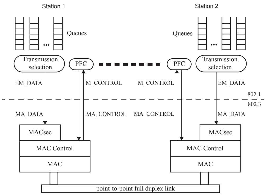
Figure 36-1—PFC peering
PFC allows link flow control to be performed on a per-priority basis. In particular, PFC is used to inhibit transmission of data frames associated with one or more priorities for a specified period of time. PFC can be enabled for some priorities on the link and disabled for others.
A VLAN unaware end station can use PFC by sending traffic as priority-tagged and by ignoring the VID in received frames. Given that BPDUs, for example, are sent untagged and can bypass the output queues, it is strongly recommended for the default priority of a port to not have PFC enabled.
NOTE—The LLC-SAP of a Bridge Port can host a management protocol stack that uses PFC-enabled priorities, and these management frames can bypass the output queues. In this situation PFC can fail to provide insurance against these frames overflowing the buffer in the remote station of the link.
36.1.2 PFC primitives
PFC is invoked through the M_CONTROL PFC primitives (see 6.6.1). A system client wishing to inhibit transmission of data frames on certain priorities from the remote system on the link generates an M_CONTROL.request primitive specifying:
a) The globally assigned 48-bit multicast address 01-80-C2-00-00-01;
b) The PFC opcode (i.e., 01-01); and
c) A request_operand_list with two operands indicating, respectively, the set of priorities addressed and the lengths of time for which it wishes to inhibit data frame transmission of the corresponding priorities.
NOTE—By definition, a point-to-point full-duplex link comprises exactly two stations, thus there is no ambiguity regarding the destination station’s identity. The use of a well-known multicast address does not require a station to know, and maintain knowledge of, the individual 48-bit address of the other station.
Over an IEEE 802.3 link layer, when PFC is enabled on a port for at least one priority, the IEEE 802.3-2012 Annex 31B PAUSE mechanism is not used for that port (see IEEE Std 802.3-2012, Annex 31D).
As a result of the processing of the PFC M_CONTROL.request, the peering PFC station receives a PFC M_CONTROL.indication primitive.
The parameters of the PFC M_CONTROL.indication are
d) The PFC opcode (i.e., 01-01); and
e) A indication_operand_list with two operands indicating, respectively, the set of priorities addressed and the lengths of time for which data frame transmission of the corresponding priorities has to be inhibited.
The request_operand_list of a PFC M_CONTROL.request and the indication_operand_list of a PFC M_CONTROL.indication are composed of the following operands:
f) priority_enable_vector: a 2-octet field, with the most significant octet being reserved (i.e., set to zero on transmission and ignored on receipt). Each bit of the least significant octet indicates if the corresponding field in the time_vector parameter is valid. The bits of the least significant octet are named e[0] (the LSB) to e[7] (the MSB). Bit e[n] refers to priority n. For each e[n] bit set to one, the corresponding time[n] value is valid. For each e[n] bit set to zero, the corresponding time[n] value is invalid.
g) time_vector: a list of eight 2-octet fields, named time[0] to time[7]. The eight time[n] values are always present regardless of the value of the corresponding e[n] bit. Each time[n] field is a 2-octet, unsigned integer containing the length of time for which the receiving station is requested to inhibit transmission of data frames associated with priority n. The field is transmitted most significant octet first, and least significant octet second. The time[n] fields are transmitted sequentially, with time[0]
transmitted first and time[7] transmitted last. Each time[n] value is measured in units of pause_quanta, equal to the time required to transmit 512 bits of a frame at the data rate of the MAC. Each time[n] field can assume a value in the range of 0 to 65 535 pause_quanta.
36.1.3 Detailed specification of PFC operation
36.1.3.1 Processing PFC M_CONTROL.requests
Invoking the PFC M_CONTROL.request results in the invocation of the appropriate link layer service request. For IEEE 802.3 link layers the PFC M_CONTROL.request is mapped to a PFC MA_CONTROL.request (IEEE Std 802.1AC). If PFC is not enabled for priority n, then PFC requests with e[n] set to one and time[n] different than zero (see 36.1.2) should not be generated.
NOTE—In the IEEE 802.1Q architecture frames coming from the LLC, including BPDUs, bypass the priority queues and therefore are not subject to PFC. However, in some implementations frames coming from the LLC can pass through the priority queues. In this case, it is not recommended to enable PFC for the priority to which BPDUs are assigned (usually priority 7).
36.1.3.2 Processing PFC M_CONTROL.indications
The PFC Receiver entity (see 36.2.2) maintains and makes available to Transmission Selection the vector of the Priority_Paused[n] variables, indicating the state of each of the eight priorities. Each Priority_Paused[n] variable is a boolean. When Priority_Paused[n] is FALSE, priority n is not in paused state. When Priority_Paused[n] is TRUE, priority n is in paused state.
Figure 36-2 shows the PFC state diagram for priority n. If PFC is not enabled for priority n, then the PFC state diagram does not apply to priority n and Priority_Paused[n] is FALSE.
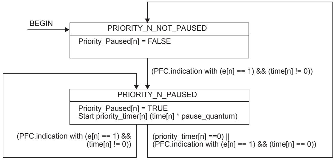
Figure 36-2—PFC Receiver state diagram for priority n
Upon receipt of a PFC M_CONTROL.indication, the PFC Receiver programs up to eight separate timers, each associated with a different priority, depending on the priority_enable_vector. For each bit in the priority_enable_vector that is set to one, the corresponding timer value is set to the corresponding time value in the time_vector parameter. Priority_Paused[n] is set to TRUE when the corresponding timer value (i.e., priority_timer[n]) is nonzero. Priority_Paused[n] is set to FALSE when the corresponding timer value (i.e., priority_timer[n]) counts down to zero. A time value of zero in the time_vector parameter has the same effect as the timer having counted down to zero. If PFC is not enabled for priority n and a PFC indication is received with e[n] set to one, then the time[n] parameter is ignored (i.e., the primitive is processed as if e[n] was set to zero).
NOTE—A priority_enable_vector with all bits set to zero is legal and equivalent to a no-op.
36.1.3.3 Timing considerations
For effective flow control on a point-to-point full-duplex link, it is necessary to place an upper bound on the length of time that a device can transmit data frames after receiving a PFC M_CONTROL.indication with e[n] set to one in the priority_enable_vector and a nonzero time[n] in the time_vector operands.
If MACsec is not supported, a queue shall go into paused state in no more than 614.4 ns since the reception of a PFC M_CONTROL.indication that paused that priority. This delay is equivalent to 12 pause quanta (i.e., 6 144 bit times) at the speed of 10 Gb/s, 48 pause quanta (i.e., 24 576 bit times) at the speed of 40 Gb/s, and 120 pause quanta (i.e., 61 440 bit times) at the speed of 100 Gb/s.
If MACsec is used, a queue shall go into paused state in no more than 614.4 ns + ‘SecY transmit delay’ (see Table 10-1 of IEEE Std 802.1AE-2006 [B6]) since the reception of a PFC M_CONTROL.indication that paused that priority. The ‘SecY transmit delay’ is defined as the wire transmit time for a maximum sized MPDU + 4 times the wire transmit time for 64 octet MPDUs. For a 2 000-byte frame the ‘SecY transmit delay’ is 8*(2 000+20) + 8*4*(64+12+4+20) = 19 360 bit times.
NOTE 1—19 360 bit times is an appropriate value for ‘SecY transmit delay’ for speeds up to 10 Gb/s. Support for the speeds of 40 Gb/s and 100 Gb/s can require a higher value.
If MACsec is supported but not used, the delay computation has to take into account the MACsec Bypass Capability (MBC) bit in the PFC configuration TLV of DCBX (D.2.11), that indicates if the link peer needs the extra time for MACsec. If the MBC bit is set to zero, the maximum PFC delay is 614.4 ns. If the MBC bit is set to one, the maximum PFC delay is 614.4 ns + ‘SecY transmit delay’.
NOTE 2—In addition to the above delays, system designers should take into account the delay of the PHY and of the link segment when designing devices that implement the PFC operation to ensure frames are not lost due to congestion (see Annex O for additional discussion on this topic).
36.2 PFC aware system queue functions
Figure 36-3 illustrates the architecture of the queue functions of a PFC aware system when Link Aggregation is not used. These functions offer a service to higher layers that utilizes a single instance of the ISS or EISS to connect to the lower layers. In Figure 36-3, two major blocks are outlined with dotted boundaries:
a) The PFC Initiator block, in the right of Figure 36-3 (see 36.2.1); and
b) The outbound queue block, in the left of Figure 36-3 (see Figure 22-2).
The remaining entities illustrated in Figure 36-3, other than the PFC Receiver entity, are part of the IEEE 802.1 architecture and are not further discussed here.
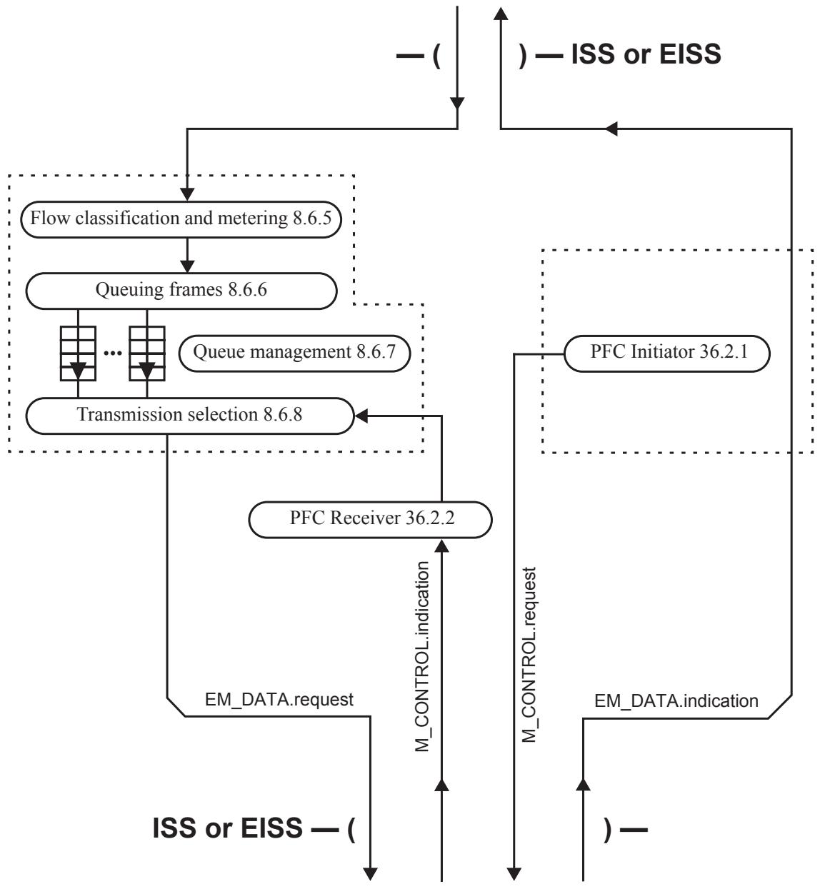
Figure 36-3—PFC aware system queue functions
36.2.1 PFC Initiator
The PFC Initiator entity generates M_CONTROL PFC requests using the M_CONTROL.request primitive (see 36.1.3.1) when appropriate (e.g., when an input buffer reaches a certain threshold).
36.2.2 PFC Receiver
The PFC Receiver entity processes the M_CONTROL.indication primitives as specified in 36.1.3.2. In addition, the PFC Receiver maintains and makes available to Transmission Selection the vector of the Priority_Paused[n] variables, indicating the state of each of the eight priorities.
The PFC Receiver entity acts per physical port. When Transmission Selection is running above Link Aggregation, each PFC Receiver entity processes the M_CONTROL.indication primitives as specified in 36.1.3.2, and maintains and makes available to Transmission Selection the vector of the Priority_Paused[n] variables, indicating the state of each of the eight priorities of that physical link, as shown in Figure 36-4.
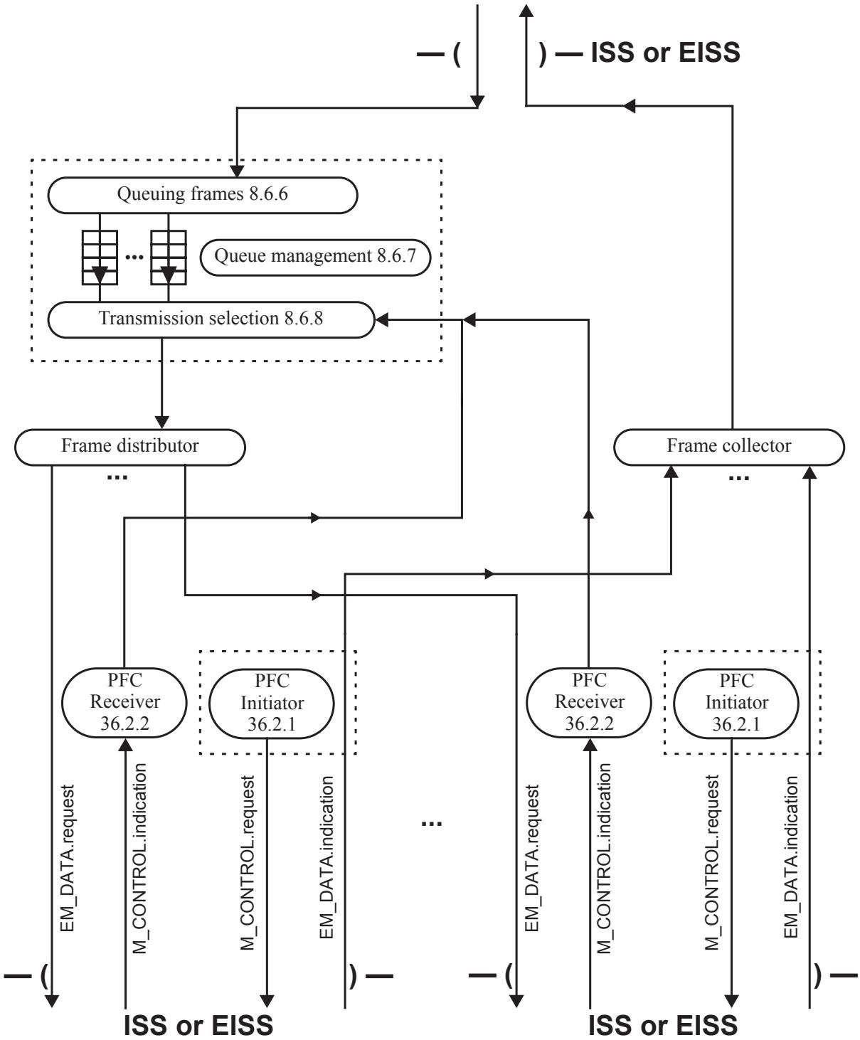
Figure 36-4—PFC aware system queue functions with Link Aggregation
37 Enhanced Transmission Selection (ETS)
37.1 Overview
This clause provides definitions and an operational model for priority processing and bandwidth allocation in end stations and Bridges in a Data Center Bridging (DCB) environment. Using Priority-based processing and bandwidth allocations, different traffic classes with different types of traffic such as LAN, Storage Networking, Clustering, and management can be configured to provide bandwidth allocation, or best effort transmit characteristics.
In order to accomplish this, the following are provided:
a) A set of bandwidth configuration parameters that are used to configure the percentage of bandwidth assigned to each traffic class.
b) A set of characteristics that an ETS enabled transmitter is required to follow.
c) A means of communicating priority-to-traffic class allocations to neighboring systems (DCBX; see Clause 38).
37.1.1 Relationship to other transmission selection algorithms
If ETS is used in conjunction with the strict priority and credit-based shaper algorithms, then attention should be paid to assignment of traffic classes as specified in 34.5.
37.2 ETS configuration parameters
The following ETS configuration parameters exist for each ETS enabled port:
a) numTrafficClassesSupported: Indicates the number of traffic classes supported by a port. This value has a minimum of 3 (see 37.3) and a maximum of 8.
b) TCPriorityAssignment(P): For each supported priority, P, the traffic class to which that priority P is assigned (see 37.1.1). A traffic class only operates with the ETS algorithm if it is assigned to do so by the Transmission Selection Algorithm Table (see 8.6.8); i.e., the entry in the table for that traffic class is assigned the value 2 (see Table 8-5).
c) TCBandwidth(N): For each traffic class N, the percentage of the available bandwidth assigned to that traffic class. The total for all traffic classes is equal to 100% (see 37.3).
Configuration of ETS parameters shall be done via DCBX (see Clause 38).
37.3 ETS algorithm
The ETS algorithm provides allocation of bandwidth to traffic classes. The algorithm allows bandwidth intensive and loss sensitive traffic to share the network while allowing coexistence with low latency traffic using the strict priority and credit-based shaper algorithms. Since there are a number of variants of bandwidth sharing algorithms (such as weighted round robin) that provide appropriate bandwidth sharing, a detailed algorithm is not specified. Any algorithm is allowed as long as it meets the specified performance requirements.
NOTE 1—While a traffic class is often referred to as a queue, it is not necessarily a single FIFO data structure. The ETS algorithm is used to determine when an ETS traffic class has a frame available to transmit. The ordering requirements in 8.6.6 are the only constraint of this standard on the order in which frames in a traffic class are transmitted. The determination of which frame in the traffic class to send may be done in an implementation specific manner as long as those ordering requirements are satisfied. For example, an implementation might organize the traffic class as a set of
FIFO queues with each FIFO queue containing the frames from a priority, VLAN or a source port. Such FIFO queues might be serviced with strict priority, weighted round robin or other bandwidth distribution algorithm.
For the purposes of the ETS algorithm, Available Bandwidth is defined as the link bandwidth remaining after traffic classes not assigned to Transmission selection algorithm 2, and Vendor Specific (see Table 8-5) are serviced. The effect of Vendor Specific algorithms to Available Bandwidth is outside the scope of this standard.
The ETS algorithm shall provide the ability to configure traffic classes to share bandwidth according to the following:
a) Allow one or more priorities to be assigned to a traffic class;
NOTE 2—All priorities within a traffic class typically share similar traffic handling requirements (e.g., loss and bandwidth).
b) Allow bandwidth to be configured for each traffic class with a granularity of 1%. The configured bandwidth indicates the percentage of Available Bandwidth that can be used by the traffic class when all other traffic classes are consuming their configured bandwidth.
c) For traffic classes for which the transmission selection algorithm is ETS (i.e., Transmission selection algorithm 2 in Table 8-5), select frames for transmission from the traffic class queues such that the bandwidth consumed by the traffic class approaches its percentage of Available Bandwidth. The traffic class consumes less than its percentage of Available Bandwidth when the offered load for that traffic class is less than its percentage of Available Bandwidth, in that case the remainder of its percentage of Available Bandwidth can be used by other traffic classes. A traffic class can consume more than its percentage of Available Bandwidth when the offered load of other traffic classes results in those traffic classes consuming less than their percentage of Available Bandwidth. Allocation of any excess Available Bandwidth is implementation specific.
d) When all traffic classes are offered enough load to consume their share of available bandwidth, and there is no offered load in the traffic classes using transmission selection algorithms other than ETS, the bandwidth received from an ETS traffic class shall deviate from its allocation by no more than 10% of the available bandwidth when measured over a period of 10 000 000 bit times using maximum sized frames during a time period when no PFC frames are received (i.e., no congestion).
NOTE 3—The measurement window is derived from an approximate number of bits in 500 frames (i.e., 500 frames 2000 bytes per frame 8 bits per byte rounded up to 10 000 000).
NOTE 4—Allowed deviation of +/-10% allows for variations of traffic (e.g., burstiness) over the specified measurement window and provides balance between precision and implementation flexibility.
e) At least 3 traffic classes shall be supported per port. A minimum of 3 traffic classes allows a minimum configuration such that one ETS traffic class contains priorities which have PFC enabled, one ETS traffic class contains priorities which have PFC disabled, and one traffic class using strict priority.
37.4 Legacy configuration
Subclause 8.6.8 specifies strict priority scheduling as default behavior. This can be achieved by configuring the Transmission selection algorithm value for a traffic class to 0 (see Table 8-5).
Subclause 8.6.6 specifies the default priority to traffic class mapping. There is no change to such mapping when ETS is used.
38 Data Center Bridging eXchange protocol (DCBX)
38.1 Overview
This clause details the DCBX, which is used by DCB devices to exchange configuration information with directly connected peers. The protocol may also be used for misconfiguration detection and for configuration of the peer.
This standard describes the base protocol, which comprises state machines and TLVs for capability exchange. For each feature that is supported by DCBX, the attributes that are to be exchanged specify
a) The attributes to be exchanged;
b) How the attributes are used for detecting misconfiguration; and
c) What action needs to be taken when a misconfiguration is detected.
The information listed above is specified for the following:
d) ETS;
e) PFC; and
f) Application Priority Configuration TLV.
38.2 Goals
The goals of DCBX are as follows:
a) Discovery of DCB capability in a peer port; for example, it can be used to determine if two link peer ports support PFC.
b) DCB feature misconfiguration detection: DCBX can be used to detect misconfiguration of a feature between the peers on a link. Misconfiguration detection is feature-specific because some features allow asymmetric configuration.
c) Peer configuration of DCB features: DCBX can be used by a device to perform configuration of DCB features in its peer port if the peer port is willing to accept configuration.
38.3 Types of DCBX attributes
Three types of DCBX attributes are exchanged:
a) Informational attributes (see 38.3.1);
a) Asymmetric attributes (see 38.4.1); and
b) Symmetric attributes (see 38.4.2).
38.3.1 Informational attributes
Informational attributes are exchanged via LLDP without any participation in a DCBX state machine.
38.4 DCBX and LLDP
DCBX uses Link Layer Discovery Protocol (LLDP) (see IEEE Std 802.1AB) to exchange attributes between two link peers. LLDP is a unidirectional protocol. It advertises connectivity and management information about the local station to adjacent stations on the same IEEE 802 LAN.
DCB exchanged attributes are packaged into Organizationally Specific TLVs. The OUI used for the DCBX TLV is the IEEE 802.1 OUI (i.e, 0x0080c2).
DCBX state machine transitions are based on the DCBX objects in the LLDP MIB module. Operation of the DCBX state machine may affect the values of the DCBX objects in the LLDP MIB module.
A port capable of any DCB feature shall have the capability for DCBX to be administratively disabled. The default state for DCBX is enabled.
DCBX is expected to operate over a point-to-point link. If multiple LLDP peer ports running DCBX are detected, then DCBX should behave as if the peer port’s DCBX TLVs are not present until the multiple LLDP peer port condition is no longer present. However, a transition in LLDP peer port may occur in some circumstances (e.g., such as a transition from system boot to system operation). Therefore, when it is detected that the number of peer ports running DCBX exceeds 1 for a period longer than the longest TTL of any of the peers, a multi-peer condition is detected. During the time when the multi-peer condition has not been detected the DCBX data from the most recent DCBX peer shall be used. An LLDP peer port is identified by a concatenation of the chassis ID and port ID values transmitted in the LLDPDU. A DCBX peer port is a LLDP peer port that is sending DCBX TLVs.
DCBX defines two different types of attribute passing mechanisms:
a) Asymmetric: the passing of a attribute from one port to its peer port. In this case, the desired configuration for the peer may not match the local configuration; and
b) Symmetric: the passing of a attribute from one port to its peer port with objective of both ports utilizing the same attribute value.
38.4.1 Asymmetric attribute passing
38.4.1.1 Overview
Two types of TLV are passed for Asymmetric attribute Passing:
a) Configuration TLV: Provides current operational state and Willing bit. The received Willing bit is not used by the state machine, but instead provided to higher layers to provide an indication of the expected behavior of the remote port. The presence of the willing bit set to 1 indicates to the remote port that the local port is willing to accept a configuration for the specific attribute for which the willing bit is set.
b) Recommendation TLV: Provides recommendation for the operational state of remote port. Transmitted only if the local port is configured to make recommendations in which case it is transmitted in all LLDPDUs. Transmitted regardless of the “willingness” of the remote port.
NOTE—An implementation is allowed to send a recommendation TLV or a configuration TLV or both.
38.4.1.2 Asymmetric state variables
LocalWilling: Indicates that the local port has been administratively configured to accept recommendations. This value is included in the Willing bit of Configuration TLVs transmitted by this port. A local port may be configured as not Willing.
OperParam: The current operational value of the attribute on the local port. This value is included as the attribute in the Configuration TLVs.
LocalAdminParam: The administratively configured value for the attribute. This becomes the operational value of the attribute by default, and the operational value may be overridden if the local port accepts a recommendation from the remote port.
RemoteParam: The attribute received in the last Recommendation TLV. This variable is set to NULL if the remote LLDP database contains no Recommendation TLV.
DCBXMapping: A function that maps the received parameters to the capabilities of the receiving port.
38.4.1.3 Asymmetric state machine
The Asymmetric State Machine is depicted in Figure 38-1.
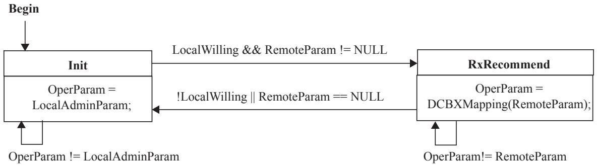
Figure 38-1—DCBX Asymmetric State Machine
38.4.2 Symmetric attribute passing
38.4.2.1 Overview
For Symmetric attribute passing one type of TLV is used:
a) Configuration TLV. This TLV always carries the current local operational state and a Willing (W) bit.
A port that sets the W bit is considered Willing. A Willing port shall set its operational attribute to that indicated in the received TLV if the received TLV has the W bit set to zero. If both the local port and remote port are willing, then the attribute values of the port with the lower numerical MAC address shall take precedence.
38.4.2.2 Symmetric state variables
LocalWilling: Indicates that the local port has been administratively configured to accept the attribute from the remote port. This value is included in the Willing bit of DCBX TLVs transmitted by this port.
RemoteWilling: rwTrue indicates that the Willing bit was set in the last TLV received. rwFalse indicates that the Willing bit was not set in the last TLV received. This variable is set to rwNull if the remote LLDP database contains no Willing bit.
LocalMAC: The MAC address of the local port.
RemoteMAC: The MAC address of the remote port.
OperParam: The current operational value of the attribute on the local port. This value is included as the attribute in the DCBX TLV.
RemoteParam: Contains the value of the last attribute (i.e., the operational value of the remote port) received in the TLV. This variable is set to NULL if the remote LLDP database contains no TLV.
LocalAdminParam: The administratively configured value for the attribute. This becomes the operational value of the attribute by default, and may be overridden if the local port accepts the attribute from the remote port.
DCBXMapping: A function that maps the received parameters to the capabilities of the receiving port.
NOTE—Through observation of the states and state variables it is possible to determine that the state machine is in the process of passing attributes. This knowledge may be useful for clients of DCBX. For example, a client may wish to delay use of the link while the DCBX state machine is in the process of passing and possibly setting attributes. A “Pending” indication indicating that the state machine is in this process may be created by the following equations:
$$
\text { Pending } = \text { RemoteParam } = = \text { NULL }
$$
$$
\|! \text { LocalWilling } \& \& \text { RemoteWilling } = = r w \text { True } \& \& \text { OperParam }! = \text { RemoteParam };
$$
38.4.2.3 Symmetric state machine
The Symmetric state machine is depicted in Figure 38-2.
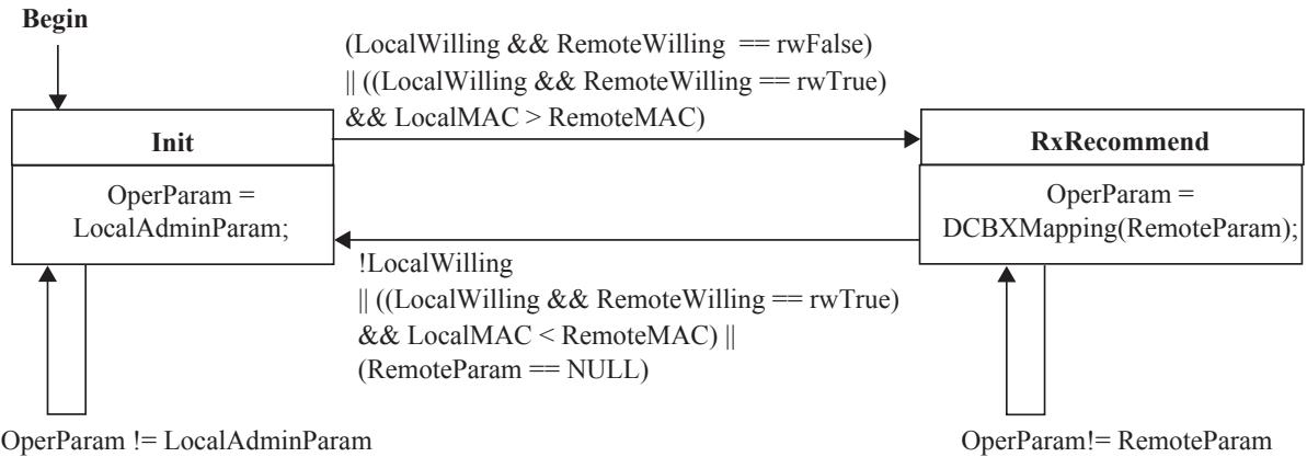
Figure 38-2—Symmetric State Machine
39 Multiple I-SID Registration Protocol (MIRP)
MIRP defines an MRP application (10.1) that provides the ability to flush learned MAC Address Entries held in the FDB of an I-component on a per-I-SID basis. MIRP makes use of MRP Attribute Declaration (MAD) and MRP Attribute Propagation (MAP), which provide the common state machine descriptions and the common attribute propagation mechanisms defined for use in MRP-based applications. The MRP architecture, MAD, and MAP are defined in Clause 10.
In a PBBN, the assignment of S-VIDs and I-SIDs to VIPs is often fixed, and the overhead of signaling the creation of Dynamic VLAN Registration Entries among I-components is undesirable. It can nevertheless be necessary to signal the need to flush the I-components’ FDBs of learned MAC address information. For example, one could configure a point-to-point service that is dual-homed (has two I-components) at each end of the service, only two of which (one at each end) are active at any one time. A failure that causes one I-component to take over from the other requires that the active I-component at the other end of the service forget its associations of C-MAC addresses to the failed I-component’s B-MAC address. Therefore, the MIRP application supports the Registration Fixed (New propagated), instead of the Registration Fixed (New ignored), value in the Registrar Administrative Controls.
The function of MIRP can be performed by MVRP. However, in an I-component with one S-VID per VIP requires 4094 MVRPDUs, one for each VIP, to signal a simultaneous topology change on all 4094 S-VIDs, whereas it can signal those same topology changes with a single Multiple I-SID Registration Protocol Data Unit (MIRPDU) through the PIP.
39.1 MIRP overview
MIRP is an extension of MVRP (11.2) for use in I-components and B-components. The extensions in both I-components and B-components are as follows:
a) The attribute values carried by the MIRPDUs are 24-bit I-SID values, rather than 12-bit VIDs in an MVRPDU.
b) A MIRP Participant can only be a New-Only Participant (10.6), so the Registrar Administrative Controls can take only the value, Registration Fixed (New propagated).
c) MIRP uses the Nearest Customer Bridge group address (Table 8-1) or the Default Backbone Destination from the CBP’s Backbone Service Instance table (6.11) instead of an MRP Application address from Table 10-1, so a Provider Bridge forwards frames containing MIRPDUs normally, while a Customer Bridge filters them.
In an I-component only, the extensions are as follows:
d) A VIP in an I-component can be attached to an MVRP Participant or to a MIRP Participant, but not to both.
e) An MVRP to MIRP attributes translation function (39.2.1.1) enables interoperation between the MVRP and MIRP Participants in the I-component.
f) There is only one MIRP Participant and one instance of the MIRP application per PIP.
In a B-component only, the extensions are as follows:
g) MIRP Participants are placed on zero or more CBPs, and on at most one non-CBP Port in the B-component.
h) MAP (10.3) operates among MIRP MAD components only, using 24-bit MIRP I-SID values.
Figure 39-1 illustrates the architecture of MVRP and MIRP in an I-component. The arrows showing the relationship between the MVRP or MIRP applications and the FDB in the MAC Relay Entity have been omitted from Figure 39-1, but these relationships are the same as those shown in Figure 11-1.
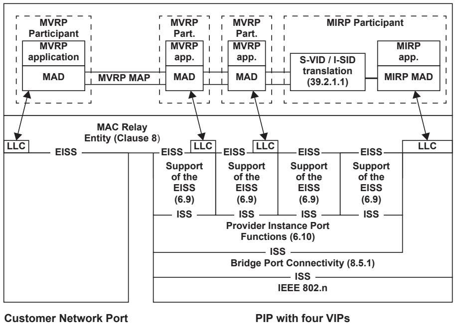
Figure 39-1—Operation of MIRP in an I-component
The architecture of MIRP in a B-component is illustrated in Figure 39-2. One management Port and one CBP are shown, although any number of CBPs can be supported. (See 39.2.2 for an alternate model.)
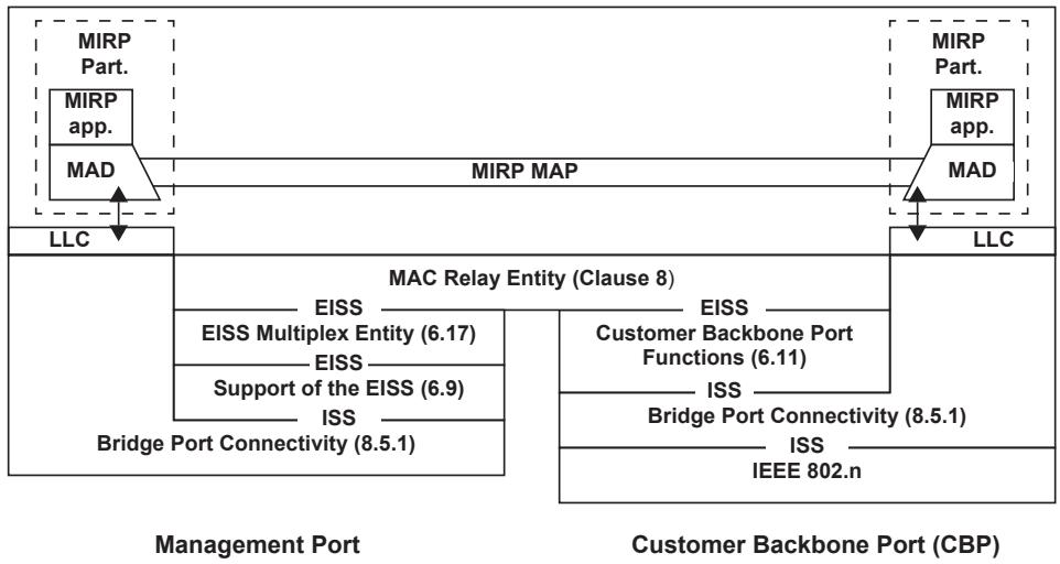
Figure 39-2—Operation of MIRP in a B-component
39.1.1 Behavior of I-components
Since PBBs are insulated from C-MAC addresses by the I-TAG, MVRP Participants in I-components are peers of MVRP Participants in other I-components, and not with MVRP Participants attached to PNPs in B-components or BCBs. In the case that an I-component is configured for some number of VIPs, each serving some number of VLANs, a single MIRPDU transmitted or received over the PIP takes the place of the individual MVRPDUs that would otherwise be transmitted or received over those VIPs.
An I-component supporting MIRP shall
a) Implement the MIRP application as indicated in 39.2;
b) Implement an MVRP/MIRP attributes translation function as indicated in 39.2.1.1; and
c) Support operation only as an MRP New-Only Participant (10.6).
39.1.2 Behavior of B-components
As illustrated in Figure 39-2, there are any number of MIRP Participants in a B-component, each on a CBP, and each containing an instance of the MIRP application and a MIRP MAD, with the MADs interacting via MAP. In addition, at most one MIRP Participant is attached to a Port that is not a CBP. This port can be a PNP, or a Management Port with no attachment to an external LAN. The latter case is shown in Figure 39-2.
A B-component supporting MIRP shall
a) Implement the MIRP application as indicated in 39.2; and
b) Support operation as an MRP New-Only Participant (10.6).
39.2 Definition of the MIRP application
39.2.1 Definition of MRP elements
39.2.1.1 S-VID and I-SID mapping in an I-Component
MVRP MAP (11.2.1, 10.3) propagates information among the MVRP MADs and the MIRP MAD. But, since MVRP MADs support 12-bit VID values, and the MIRP MAD supports 24-bit I-SID values, a translation function is required to map the VIP-ISID to or from S-VIDs statically configured on the VIP.
When a “new” MIRP declaration is received on a given VIP as a result of receiving an MIRPDU from the attached LAN (MAD_Join.indication), the MAD_Join.request with the new parameter set that is generated by the MIRP MAD is translated to a MAD_Join.request for each S-VLAN with a Static VLAN Registration Entry of Registration Fixed (New propagated) on that VIP. When any MIRP declaration with the new parameter is received on a given VIP as a result of a request from MAP (MAD_Join.request) for any S-VLAN with a Static VLAN Registration Entry of Registration Fixed (New propagated) on that VIP, it is translated to a MAD_Join.request for that VIP’s I-SID with the new parameter set. All other requests are discarded.
NOTE—If many S-VLANs are configured per VIP, then using an MVRP New-Only Participant (11.2.6) offers more detailed control of MAC address flushing than does MIRP, at some cost in bandwidth and processing effort.
39.2.1.2 I-SID translation in a B-component
If a Backbone Service Instance table (6.11) on a CBP implements the Local Service Instance Identifier (Local-SID) field, the attribute values encoded in MIRPDUs by the MIRP Participants in CBPs shall be Local-SID values. The attribute values transferred by MAP in the B-component and encoded in MIRPDUs by the MIRP Participant on a non-CBP Port shall be Backbone-SID values.
39.2.1.3 MAP Context for MIRP
The MIRP MAP Context identifies the set of Ports that form the applicable topology for the propagation of the MIRPDUs among the MIRP Participants. Within a single I-component, the MIRP Participants on PIPs behave as independent end stations from an I-SID registration perspective and correspondingly there is no further propagation of the MIRPDUs. As described in 39.2.1.1, the S-VID/I-SID translation function allows the MIRP MADs to communicate with MVRP MADs. Thus, New messages can propagate throughout a concatenated network of PBNs (via MVRP) and PBBNs (via MIRP).
Within a single B-component, there may be multiple MIRP MAP Contexts. The reason for having separate MIRP MAP Contexts is to collect and distribute MIRP information bound for or received from MIRPDUs that use different combinations of B-VIDs and MAC addresses, as chosen by the network administrator via managed objects (12.16.1). A Port in a B-component supporting a MIRP Participant, either an administratively chosen PNP or Management Port, or a CBP, can participate in more than one MIRP Context. The Ports of a B-component comprising a given MIRP Context is a PNP or Management Port, plus the set of CBPs on the B-component for which the following are true:
a) The CBP is in the Member set (8.8.9) for the B-VID; and
b) If the MIPRDU destination_address for the CBP is the Default Backbone Destination address, the FDB does not filter that B-VID and MAC address on the Port.
In a B-component, the parameters controlling MIRPDU addressing (39.2.1.6) control the number of MIRP MAP Contexts as follows:
c) If a single destination_address and B-VID are used for all MIRPDUs [item (a) in 39.2.1.6] then there is a single MIRP MAP Context.
d) If the Nearest Customer Bridge group address (Table 8-1) used with a B-VID from a Backbone Service Instance table [item (b) in 39.2.1.6], then there is a separate MIRP MAP Context for each B-VID that appears in the CBP Backbone Service Instance table (6.11) of any CBP with a configured MIRP Participant.
e) If the Default Backbone Destination option for the MIRPDU destination_address is used [item (c) in 39.2.1.6], then there is a separate MIRP MAP Context for each combination of Default Backbone Destination and B-VID in the CBP Backbone Service Instance table (6.11) of any CBP with a configured MIRP Participant.
The MIRP Participant on a CBP propagates information for a particular I-SID between the CBP MIRP MAD and the appropriate MIRP MAP Context, as determined by the CBP’s Backbone Service Instance table and the addressing selection parameters (39.2.1.6). Thus, a CBP MIRP MAD may exchange requests and indications with multiple MIRP MAP Contexts.
NOTE 1—MIRPDUs cannot pass through the CBP functions (6.11) because they have no I-TAG. Readers can see from Figure 39-2 and Figure 39-3 that this isolates the MIRPDUs exchanged among PNPs, Management Ports (and CBPs in Figure 39-3) over the backbone from the MIRPDUs exchanged over the various I-component–to–CBP links.
NOTE 2—See 39.2.2 for an alternate model for MIRP operation in a B-component and the MIRP MAP Context.
39.2.1.4 MAP Context identification for MIRP
In an I-component, there is only one MAP Context.
In a B-component, the vlan_identifier and destination_address of an MIRPDU received on a PNP or Management Port serve to identify the MIRP MAP Context as defined in 39.2.1.3. In a CBP, the MIRP MAP Context used to propagate information is determined by CBP Backbone Service Instance table (6.11) entry for each I-SID value propagated. An MIRPDU that corresponds to no MAP Context configured on the receiving B-component is discarded.
39.2.1.5 MIRP application addressing in an I-component
The source MAC address for an MIRPDU is the MAC address of the PIP.
The destination MAC address for an MIRPDU transmitted from a PIP shall be the Nearest Customer Bridge group address, (01-80-C2-00-00-00, see Table 8-1).
MIRPDUs transmitted and received on a PIP carry no VLAN tag and have no vlan_identifier.
NOTE—An MIRPDU transmitted by a PIP needs no B-TAG because it is connected to a CBP (see Figure 25-4) that either has an MIRP Participant to receive the untagged MIRPDU, or if not, discards the MIRPDU (39.2.1.3).
39.2.1.6 MIRP application addressing in a B-component
The source MAC address for an MIRPDU is the MAC address of the Port from which it is transmitted.
For a MIRP Participant attached to a CBP, the destination MAC address for an MIRPDU transmitted shall be the Nearest Customer Bridge group address, (01-80-C2-00-00-00, see Table 8-1). MIRPDUs shall be transmitted from a CBP without a VLAN tag.
For the MIRP Participant attached to a PNP or Management Port, there are three choices, selectable via managed variables [see item (k) in 12.16.1.1.3], for the destination MAC address and B-VLAN on transmitted MIRPDUs:
a) The destination_address is the Nearest Customer Bridge group address (Table 8-1), and the vlan_identifier is the MIRP B-VID [item (c) in 12.16.1.2.2].
b) The destination_address is the Nearest Customer Bridge group address (Table 8-1), and the vlan_identifier is a B-VID from the CBPs’ Backbone Service Instance tables (6.11).
c) The destination_address is a Default Backbone Destination from the CBPs’ Backbone Service Instance tables (6.11), and the vlan_identifier is a B-VID from those tables.
In case (b) or case (c), it is possible that different CBPs in the serving I-SIDs in the same MIRP MAP Context (39.2.1.3) can be configured differently. For each I-SID value’s message in the MIRPDU, the MIRP Participant on the PNP or Management Port uses the Backbone Service Instance table from the CBP with the lowest numerical Port Number to determine the {destination_address, vlan_identifier} pair to use for that I-SID value.
A separate MIRPDU is transmitted for each separate MIRP MAP Context. If multiple {destination_address, vlan_identifier} pairs are generated by different I-SIDs within a single MIRP MAP Context, then the MIRP Participant shall transmit at least one MIRPDU for each distinct pair.
NOTE 1—The network administrator can use the destination_address and vlan_identifier configuration choice to optimize either for the fewest transmitted MIRPDUs by using case (a), for the fewest unnecessarily addressed I-components by using case (c), or for a balance of these two conflicting optimizations by using case (b).
NOTE 2—If different B-components in a single PBBN are configured differently for MIRP application addressing, then MIRPDUs can be lost or misinterpreted, because the different B-components can classify MIRPDUs in different MAP Contexts.
NOTE 3—See 39.2.2 for an alternate model for MIRP operation in a B-component and MIRPDU addressing.
39.2.1.7 MIRP application EtherType
The EtherType used for MIRPDUs shall be the MIRP EtherType identified in Table 10-2.
39.2.1.8 MIRP ProtocolVersion
The ProtocolVersion for the version of MIRP defined in this standard takes the hexadecimal value 0x00.
39.2.1.9 MIRP AttributeType definitions
MIRP defines a single Attribute Type (10.8.2.2) that is carried in MRP exchanges, as follows:
Attributes identified by the I-SID Vector Attribute Type are instances of VectorAttributes (10.8.1), used to identify a sequence of values of I-SIDs. The value of AttributeType used to identify the I-SID Vector Attribute Type in MRPDUs (10.8.2.2) shall be 1.
39.2.1.10 MIRP FirstValue definitions
The FirstValue field in instances of the I-SID Vector Attribute Type shall be encoded in MRPDUs (10.4) as three octets, taken to represent an unsigned binary number, and equal to the value of the VIP-ISID parameter for the VIP.
The range of permitted I-SID values that can be encoded in the FirstValue fields in MIRP is restricted to those not listed in Table 9-3.
39.2.1.11 Administrative controls
MIRP supports only the Registration Fixed (New propagated) value of the Registrar Administrative Controls (10.7.2) and this value cannot be manipulated by management. Therefore, the MRP Registrar Administrative Control (12.7.7.1, 12.7.7.2) can only take the value New propagated.
The provision of static control over the ability of Applicant state machines to participate in protocol exchanges is achieved by means of the Applicant Administrative Control parameters associated with the operation of MRP (10.7.3). Where management capability is implemented, the Applicant Administrative Control parameters can be applied and modified by means of the management functionality defined in 12.9.
The management controls in Clause 12 operate per Bridge Port, but a MIRP Participant is attached to a PIP, which is not a Bridge Port. Therefore, if MIRP is enabled on any VIP on a PIP, then the MIRP Participant is enabled on that PIP. If MIRP is disabled on all of the VIPs on a PIP, then the MIRP Participant on the PIP is disabled.
The choice of destination_address and vlan_identifier used in an MIRPDU from a B-component are made by an enumerated configuration parameter [item d) in 12.16.1.2.2] and a B-VLAN configuration parameter [item c) in 12.16.1.2.2].
39.2.2 Alternate MIRP model for B-components
An alternate model for the operation of MIRP in a B-component is illustrated in Figure 39-3. This model is perfectly interoperable with that presented in 39.2.1 and Figure 39-2, is indistinguishable in terms of required protocol behavior from that model, and thus can be used to implement MIRP. In this alternate model, there is a pair of communicating MIRP Participants in each CBP, separate from a similar pair in every other CBP, with no MIRP Participant on any PNP or management Port. The LAN-facing MIRP Participant (the right-hand MIRP Participant in Figure 39-3) corresponds to the CBP MIPR Participant described in 39.2.1. The Relay-facing MIRP Participant (the left-hand MIRP Participant in Figure 39-3) is attached to the EISS Connectivity (39.2.2.1). Its functions correspond to those of the MIRP Participant on a PNP or Management Port in 39.2.1 and Figure 39-2.
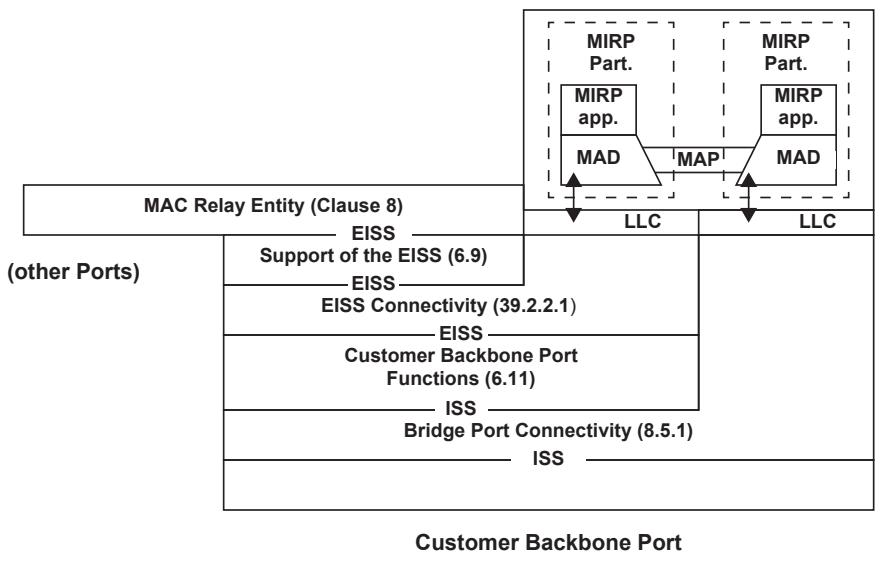
Figure 39-3—Alternate model for MIRP in a B-component
NOTE 1—Because the CBP functions (6.11) do not pass frames without I-TAGs, the Relay-facing MIRP Participant can exchange MIRPDUs only through the MAC Relay Entity, and the LAN-facing MIRP Participant only through the LAN.
NOTE 2—The only difference between the models in Figure 39-2 and Figure 39-3 that visible to an observer external to the B-component is that the alternate model can issue MIRPDUs with different source_address parameters, while a the PNP model issues all MIRPDUs with the same source_address. Since MRP and MIRP make no use of that parameter, this difference does not affect the operation of the protocol.
39.2.2.1 EISS Connectivity
The EISS Connectivity function is identical to the Bridge Port Connectivity of 8.5.1, except that it supports the EISS (6.8) instead of the ISS (IEEE Std 802.1AC).
Each EM_UNITDATA.indication provided by the lower EISS access point (Figure 39-3) shall result in a corresponding EM_UNITDATA.indication with identical parameters at each of the access points supporting the MAC Relay and Higher Layer Entities. (Only one such Higher Layer Entity is shown in Figure 39-3.) Each EM_UNITDATA.request from the EISS access point supporting the MAC Relay Entity shall result in a corresponding EM_UNITDATA.indication with identical parameters at each of the access points for the Higher Layer Entities, and a corresponding EM_UNITDATA.request with identical parameters at the lower access point. Each EM_UNITDATA.request from an ISS access point supporting a Higher Layer Entity shall result in a corresponding EM_UNITDATA.indication with identical parameters at the access points for the MAC Relay Entity, and at other access points for Higher Layer Entities, and a corresponding EM_UNITDATA.request with identical parameters at the access point for the LAN.
The MAC_Enabled, MAC_Operational, and operPointToPointMAC status parameters for the EISS access point for the MAC Relay Entity and Higher Layer Entities shall take the same value as that for the lower access point if that is present, and shall be True otherwise (i.e., if the Port is a Management Port).
39.2.2.2 Alternate MIRP MAP Context
There is a single MIRP MAP Context per CBP, that includes both of the MIRP Participants on that CBP but no MIRP Participant on any other CBP.
39.2.2.3 Alternate MIRPDU addressing
The addressing requirements for the two MIRP Participants on a CBP are different. The LAN-facing MIRP Participant behaves as described in 39.2.1.6. The Relay-facing MIRP Participant follows the rules described for the PNP or Management Port in 39.2.1.6. Since there is only one Backbone Service Instance table (6.11) per CBP, there is no ambiguity with regard to MIRPDU addressing. The MIRPDU addressing control parameters described in 39.2.1.6 apply to every Relay-facing MIRP Participant.
NOTE—The model in Figure 39-3 results in the CBPs communicating MIRP information via MIRPDUs, instead of via the MIRP MAP, as in Figure 39-2, and all of those MIRPDUs would be output to the rest of the PBBN, as well.
39.2.3 Use of “new” declaration capability
MIRP supports the Registration Fixed (New propagated) value for the Registrar Administrative Controls for a Port in a Static VLAN Registration Entry. MIRP will accept and propagate a New Message received on that Port for that VLAN and propagate it to all other Ports.
When any MIRP declaration marked as “new” is received on a given VIP, either as a result of receiving an MIRPDU from the attached LAN (MAD_Join.indication), or as a result of receiving a request from the MAP (via the S-VID/I-SID translation function [39.2.1.1]) for the MIRP Application (MAD_Join.request), any entries in the I-component’s FDB for that Port and for the VLANs corresponding to the attribute value in the MAD_Join primitive are removed.
39.2.4 Attribute value support requirements
Implementations of MIRP shall be capable of supporting all attribute values in the range of possible values that can be registered using MIRP. An I-component shall be capable of maintaining current state information for at least 4094 attributes in the range of possible values. A CBP implementation shall support the full range of attribute values that are supported, in turn, by its Backbone Service Instance table.
39.2.5 MRP Message filtering
A MIRP Participant operates in Registration Fixed (New propagated) mode only. Therefore, any MIRP Message for an attribute that is not a VIP-ISID (for an I-component) or a Local-SID or Backbone-SID (for a CBP) is ignored by a MIRP Participant.
40 Edge Virtual Bridging (EVB)
Figure 40-1 provides an overview of the EVB architecture. An end station that supports the attachment of one or more virtual stations is said to be an EVB station. Each virtual station has at least one Virtual Station Interface (VSI). Each virtual station communicates with other virtual stations or other stations on the Bridged Network via the edge relay (ER) to which it is attached (see 3.65).
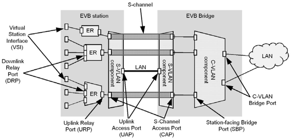
Figure 40-1—EVB architecture overview
An ER supports local relay among virtual stations and/or relay between a virtual station and other stations on the Bridged Network through an EVB Bridge. When forwarding of frames from one DRP to one or more other DRPs associated with the same ER (i.e., local relay) is not supported, then forwarding of traffic from one DRP to one or more other DRPs is performed by the EVB Bridge, utilizing reflective relay (8.6.1).
Connection between a DRP and a virtual station is achieved via a VSI. Traffic from a VSI traverses an internal LAN connecting the DRP to the virtual station. The operation of an ER does not result in any modifications to relayed frames over and above the normal tagging and untagging functions of a VLAN Bridge. ERs do not participate in, or affect, spanning tree operation; it is therefore necessary that the logical connectivity maintained within the station is always loop-free (5.24.1).
Figure 40-1 shows a 2-port ER within the EVB station; this illustrates the fact that even where a single VSI is supported by an S-channel, an ER is present in order to provide C-tagging, reserved address filtering (per Table 8-1) and support for the VSI Discovery and Configuration Protocol (VDP, Clause 41), the Edge Control Protocol (ECP), the EVB TLV (D.2.13), and LLDP (IEEE Std 802.1AB).
Each VSI instance is assigned a VSI manager ID, VSI Type Identifier (VTID), and VSI Instance Identifier (VSIID). VDP associates a VSI instance and its related VID(s), MAC address(es), GroupID(s), VSI manager ID, VTID,41 and VSIID with an SBP. Similarly, VDP de-associates a VSI instance from an SBP.
VDP can also be used to associate a single VTID with, or de-associate a single VTID from the SBP. In this case, the VSI instance does not contain any MAC addresses, VIDs, or Group IDs, and uses the wildcard VID format (41.2.9.1). Only the most recent associate command is used to configure the VTID for the SBP.
An ER supports relaying of frames associated with one or more VSIs. In order to achieve this, an ER can support two types of operation. In the first type, referred to as virtual edge bridge (VEB), traffic transferred from one DRP to another DRP of the same ER is forwarded directly by that ER. In the second type, referred to as VEPA, traffic transferred from one DRP to another DRP of the same ER is forwarded onto a single URP beyond the ER to the EVB Bridge. In this case, the EVB Bridge’s SBP is enabled with reflective relay (40.4, 8.6.1); this allows the frame to be reflected back to the same ER from which it was received by the EVB Bridge. The ER can then forward the frame to the destination. Thus, in the second mode, all traffic transits the EVB Bridge’s SBP and is subject to, for example, filtering or policing behavior associated with the EVB Bridge.
NOTE—Connection between an EVB Bridge and an ordinary end station takes place via a C-VLAN Bridge Port, not an SBP.
An S-channel is a point-to-point S-VLAN that spans a pair of Port-mapping S-VLAN components (22.6.4) and can be used to interconnect an ER and the C-VLAN component of an EVB Bridge. Multiple S-channels can share the use of a LAN. The use of multiple S-channels allows the EVB station to support multiple ERs. The endpoint of an S-channel is known as an S-channel Access Port (CAP); frames are S-tagged on entry to, and are untagged on exit from, the S-VLAN component through a CAP.
EVB TLVs (D.2.13) exchanged via LLDP allow an EVB station and an EVB Bridge to exchange information related to the use of reflective relay and other operational parameters. Each ER has an LLDP database at its URP. Each ER can also have an LLDP database at each DRP.
Each URP and each SBP has an instance of ECP (Clause 43) used to support the VDP. These instances of ECP use the Nearest Customer Bridge address as the destination for frames exchanged between the URP and SBP. VDP TLVs are packed into PDUs that are handed to ECP for delivery. ECP provides reliable delivery of VDP PDUs.
40.1 EVB architecture without S-channels
Figure 40-2 illustrates the relationship of the EVB entities to the Bridge architecture when no S-channels are supported and no Port-mapping S-VLAN components are implemented. In this configuration, the EVB station and EVB Bridge may exchange an S-channel Discovery and Configuration Protocol (CDCP) TLV over the Nearest non-TMPR Bridge address indicating that the S-VLAN component is not present. If the CDCP TLV managed object does not exist in the LLDP database, then the transmitting station or Bridge is assumed to not support S-channels. A URP or an SBP can send a CDCP TLV. If the EVB station supports the CDCP TLV then the nearest non-TPMR LLDP database is located at the URP. If the EVB Bridge supports the CDCP TLV then the nearest non-TPMR LLDP database is located at the SBP.
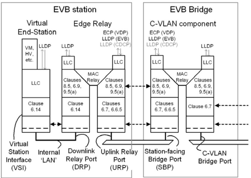
Figure 40-2—EVB architecture without S-channels
40.2 EVB architecture with S-channels
Figure 40-3 shows the relationship of the EVB entities to the Bridge architecture when S-channels are supported. In this configuration, the EVB station and Bridge build nearest non-TPMR LLDP databases at their Uplink Access Ports (UAPs) and use them to exchange CDCP TLVs. Both the EVB station and EVB Bridge set the SComp parameter in the CDCP TLV to TRUE indicating they have an S-VLAN component. The CDCP operating on the CDCP TLVs exchanged by LLDP is used to configure the S-channels.
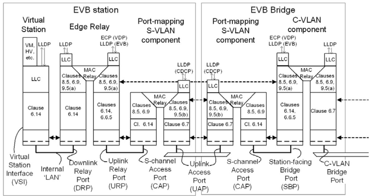
Figure 40-3—EVB archichtecture with S-channel
EVB stations and EVB Bridges use Port-mapping S-VLAN components (5.6, 22.6.4) to instantiate Schannels. Each S-channel connects a CAP on the EVB station to a CAP on the EVB Bridge. The CAP on an EVB station connects to a single URP on an ER via an internal LAN. The CAP on an EVB Bridge connects to a single SBP on the C-VLAN component via an internal LAN. There is a 1:1 relationship between a CAP and an SBP of the EVB Bridge, and a 1:1 relationship between a CAP and a URP of the EVB station. Schannel support allows the EVB station and EVB Bridge to support multiple ERs on a LAN. Each S-channel is associated with the URP of a distinct ER.
Figure 40-4 shows the relationship between S-channels and CAPs and the positioning of a station’s internal and external LANs. When S-channels are supported, each physical LAN can be used to support multiple Schannels identified on the LAN by S-tagging. The S-channels are supported by one Port-mapping S-VLAN component for each UAP. Each Port-mapping S-VLAN component within an EVB station can be identified by its single UAP. A CAP is uniquely identified by the combination of the UAP of the S-VLAN component and the S-VID of the S-channel. Each CAP attaches by internal C-tagged LANs to a single URP or SBP. The C-VLANs carried over each S-channel are determined by configuration of the EVB station and of the C-VLAN component within the EVB Bridge.
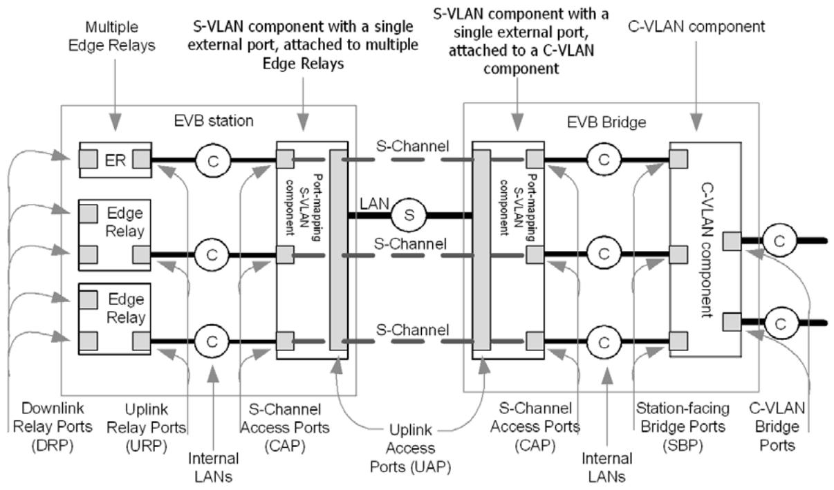
Figure 40-4—EVB components and internal LANs with S-channels
NOTE—As a result of normal Bridge behavior described in 6.9, the priority carried in the C-TAG is regenerated at the CAP to form the S-TAG priority.
The C-VLAN component of the EVB Bridge is a standard C-VLAN component (5.5) that additionally supports reflective relay (40.4, 8.6.1), the EVB LLDP TLV, and VDP.
When a UAP table entry (12.26.4.1) is created, a Port-mapping S-VLAN component is instantiated and the following actions are taken automatically:
a) The UAP is configured to
1) Admit all frames (6.9);
2) Have a PVID parameter equal to the default S-channel S-VID (6.9, 40.3);
3) Be included in the member set for the default S-channel S-VID (8.8.10);
4) Be a member of the untagged set for the default S-channel S-VID (8.8.2);
5) Be included in the member set for all S-VIDs of active S-channels.
b) An S-channel Interface table entry is created if one does not already exist for the default S-channel. This table provides the equivalent functionality of
1) Creating a CAP for the default S-channel;
2) Configuring the CAP to accept only un-S-tagged frames (6.9);
3) Setting the member set for the default S-channel’s S-VID to include the CAP;
4) Setting the CAP's PVID to the default S-channel’s S-VID;
5) Adding the CAP to the default S-channel S-VID’s untagged set;
6) Setting filters on the CAP for the Nearest Bridge and Nearest non-TPMR Bridge group MAC addresses;
7) In the case of an EVB Bridge allocating (or creating) an SBP on the C-VLAN component attached to the CAP by an internal LAN.
c) An instance of LLDP is started on the UAP transmiting a local database on the Nearest Non-TPMR Bridge Address and including the CDCP TLV.
d) CDCP is started on the UAP and configured with the parameters specified when the UAP was created.
1) If the CDCP role is “B,” then CDCP will wait for new S-channel creation requests. As new requests are found, CDCP creates new S-channel interface table entries for each new S-channel and deletes entries when S-channels are removed.
2) If the CDCP role is “S,” then CDCP uses the S-channel interface table to create the list of Schannel Identifiers (SCIDs) for the S-channels it is requesting from the “B” side.
40.3 Asymmetric EVB architecture without S-channels
Figure 40-5 and Figure 40-6 illustrate the relationship of the EVB entities to the Bridge architecture when Schannels are supported by only one side at a time; either the EVB Bridge or EVB station, but not both simultaneously. In these configurations, the EVB entity with S-channel support will advertise it has an S-VLAN component by building a nearest non-TPMR LLDP databases at its UAP and including the CDCP TLV with the parameter SComp set to TRUE. The EVB entity without S-channel support may advertise a Nearest non-TMPR Bridge LLDP database with the CDCP TLV indicating an SComp parameter set to FALSE. CDCP is assumed not to be supported by the peer EVB entity until a CDCP TLV has been received.
Each Port-mapping S-VLAN component within an EVB entity supports an internal default S-channel identified by S-VID 1 and uses it to pass untagged frames to its UAP. This default S-channel is always present in the entity supporting an S-VLAN component. In the asymmetric configurations, frames from the system without S-channel support are carried over the default S-channel within the system that has Schannel support.
40.4 EVB status parameters
In EVB Bridges and EVB Stations, an EVBMode parameter is associated with each port that provides EVB functionality. The parameter represent the EVB status of the port.
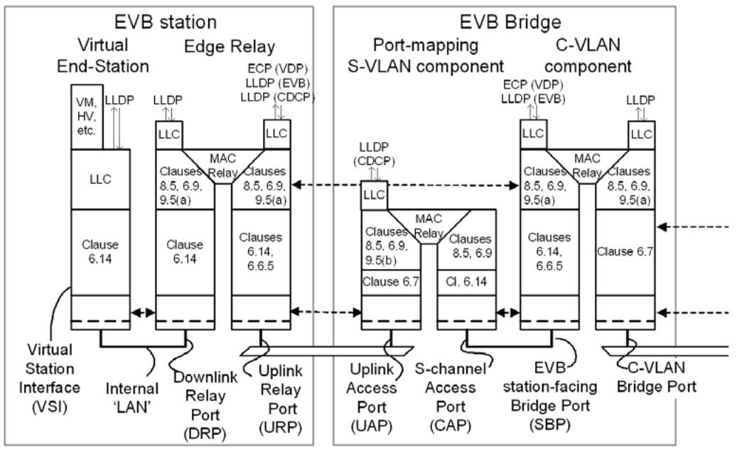
Figure 40-5—EVB architecture without S-channels, with EVB Bridge S-VLAN component
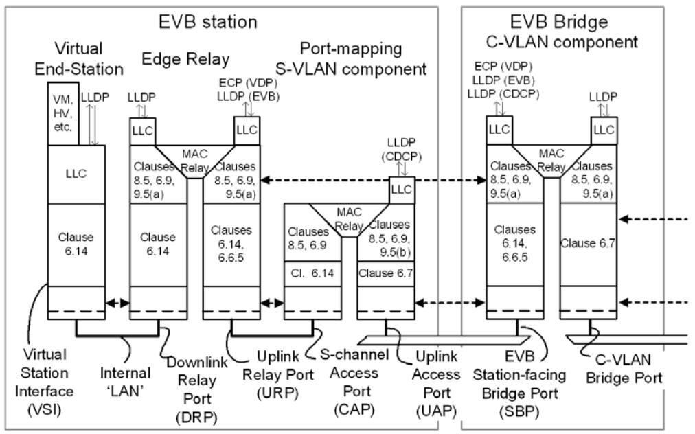
Figure 40-6—EVB architecture without S-channels, with EVB station S-VLAN component
The EVBMode parameter determines whether EVB functionality is supported, and in what mode. The parameter can take one of the following three values:
a) EVB Bridge. The port supports the functionality of an EVB Bridge.
b) EVB station. The port supports the functionality of an EVB station.
c) Not Supported. The port does not support EVB functionality. This value is assumed if the EVB status parameters are not implemented.
40.4.1 EVBMode = Not supported
If the value of the EVBMode parameter is Not Supported, then no further status parameters are available, EVB functionality is not supported, and the operation of the service associated with the port follows the normal forwarding rules for a Bridge.
40.4.2 EVBMode = EVB Bridge
If the value of the EVBMode parameter is EVB Bridge, then further parameters are available, as follows:
a) reflectiveRelayCapable. If this parameter is TRUE, then the active topology enforcement function is capable of performing reflective relay, as specified in 8.6.1; if FALSE, the active topology enforcement function is not capable of performing reflective relay.
NOTE 1—The value of the reflectiveRelayCapable parameter is an inherent property of the implementation and is not subject to administrative control.
b) operReflectiveRelayControl. If this parameter is TRUE, then reflective relay is enabled; if FALSE, reflective relay is disabled.
NOTE 2—Reflective relay is enabled if a remote EVB station has requested that it be provided (as determined by protocol exchanges between the EVB station and EVB Bridge) and the EVB Bridge is capable of providing it, or disabled if the EVB station has not requested that it be provided or the EVB Bridge is not capable of providing it.
40.4.3 EVBMode = EVB station
If the value of the EVBMode parameter is EVB station, then further parameters are available, as follows:
a) adminReflectiveRelayRequest. This parameter can take one of two values:
1) TRUE. The attached EVB Bridge is requested to enable Reflective relay.
2) FALSE. The attached EVB Bridge is requested to disable Reflective relay.
NOTE 1—The value of adminReflectiveRelayRequest is used in the EVB TLV exchanges described in D.2.13 to indicate to an attached EVB Bridge that the EVB station needs reflective relay to be provided. A given EVB station is not required to support both possible values of adminReflectiveRelayRequest.
b) operReflectiveRelayStatus. This parameter can take one of three values:
1) TRUE. The EVB Bridge has enabled reflective relay.
2) FALSE. The EVB Bridge has disabled reflective relay.
3) Unknown. It is not known whether the EVB Bridge has enabled reflective relay.
NOTE 2—The value of operReflectiveRelayStatus indicates whether the EVB Bridge has enabled reflective relay, or whether the EVB Bridge status is not currently known, as determined by protocol exchanges between the EVB station and EVB Bridge. The EVB Bridge status can be unknown during initialization or until the protocol exchanges have completed.
41 VSI Discovery and Configuration Protocol (VDP)
VDP associates (registers) a VSI instance with an Station-facing Bridge Port (SBP) of an EVB Bridge. VDP simplifies and automates virtual station configuration by enabling the movement of a VSI instance (and its related VSI Type information) from one virtual station to another or from one EVB Bridge to another. VDP supports VSI discovery and configuration across a channel interconnecting an EVB station and an EVB Bridge. VDP TLVs are exchanged between the station and the Bridge in support of this protocol.
This subclause defines the VDP TLV structure and state machines. VDP uses ECP (Clause 43) as a transport protocol for VDP TLV exchanges. Three VDP TLVs are defined as follows:
a) The VSI manager ID TLV (41.1). There is a single instance of this TLV in any ECPDU that carries VDP, and it appears as the first TLV in the ECPDU.
b) The VDP association TLV (41.2). One or more of these TLVs can appear in any ECPDU, following the VSI manager ID TLV.
c) The organizationally defined TLV (41.3).
When ECP is used as a transport protocol for VDP, ECP uses the Nearest Customer Bridge group MAC address (Table 8-1) as the destination address for ECPDUs.
NOTE 1—If there are multiple VSI managers, then their TLVs are transmitted in separate ECPDUs.
NOTE 2—Beyond the requirement stated, that the VSI manager ID TLV appears as the first TLV in ECPDUs carrying VDP, there are no further constraints placed upon how an implementation chooses to pack VDP TLVs into an ECPDU.
NOTE 3—VDP TLVs are not LLDP TLVs, and the TLV type values used in VDP TLVs are assigned from a distinct number space from those used in LLDP TLVs.
41.1 VSI manager ID TLV definition
Figure 41-1 illustrates the format of the VSI manager ID TLV.
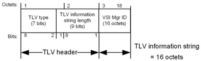
Figure 41-1—VSI manager ID TLV
The VSI manager ID TLV field definitions are contained in 41.1.1 through 41.1.3.
41.1.1 TLV type
The TLV type field takes the value shown in Table 41-1 for VSI manager ID.
41.1.2 TLV information string length
This field contains the length of the TLV information string, which is 16 octets.
Table 41-1—VDP TLV types
<table><tr><td>TLV type</td><td>Value</td></tr><tr><td>Pre-Associate</td><td>0x01</td></tr><tr><td>Pre-Associate with resource reservation</td><td>0x02</td></tr><tr><td>Associate</td><td>0x03</td></tr><tr><td>De-associate</td><td>0x04</td></tr><tr><td>VSI manager ID</td><td>0x05</td></tr><tr><td>Organizationally defined TLV</td><td>0x7F</td></tr><tr><td>Reserved for future standardization</td><td>0x00, 0x06–0x7E</td></tr></table>
41.1.3 VSI Manager ID
Identifies the database that should be accessed to get the VSI Type. The value 0 means that the station does not know what VSI Manager ID to use, indicating that the Bridge should select a default value. Any other value is interpreted as an IPv6 address, as defined in IETF RFC 4291.
41.2 VDP association TLV definitions
Figure 41-2 illustrates the format of the VDP association TLV.
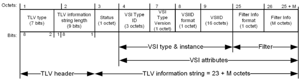
Figure 41-2—VDP association TLV
The VDP association TLV field definitions are contained in 41.2.1 through 41.2.9. The semantics of the VDP association TLV types are defined in 41.2.10.
When the VDP association TLV is sent as a response, the Status field indicates the outcome of the requested operation, and the remaining fields are populated using the information provided in the request or information provided by the EVB Bridge.
41.2.1 TLV type
The TLV type field identifies the type of the VDP association TLV, and can take any of the values shown in Table 41-1 for pre-associate, pre-associate with resource reservation, associate, or de-associate.
41.2.2 TLV information string length
This field contains the length of the TLV information string, calculated as 23 + M octets, where M is the number of octets in the filter info field (41.2.9).
41.2.3 Status
The Status field contains a 4-bit error type, encoded in bits 1–4, and four individual Boolean flags, encoded in bits 5–8.
For all requests, the error type field is reserved for future standardization; it is transmitted as 0x0 and is ignored on receipt.
For all requests, the Boolean flags are interpreted as shown in Table 41-2.
Table 41-2—Flag values in VDP requests
<table><tr><td>Name</td><td>Bit position</td><td>Interpretation</td></tr><tr><td>M-bit</td><td>Bit 5</td><td>Indicates that the user of the VSI (e.g., the virtual station) is migrating (M-bit = 1) or provides no guidance on the migration of the user of the VSI (M-bit = 0). The M-bit is used as an indicator relative to the VSI to which the user is migrating.</td></tr><tr><td>S-bit</td><td>Bit 6</td><td>Indicates that the VSI user (e.g., the virtual station) is suspended (S-bit = 1) or provides no guidance about whether the user of the VSI is suspended (S-bit = 0). A keep-alive Associate request with S-bit = 1 can be sent when the VSI user is suspended. The S-bit is used as an indicator relative to the VSI that the user is migrating from.</td></tr><tr><td>Req/Ack</td><td>Bit 7</td><td>Set to 0 to indicate that the TLV contains a request.</td></tr><tr><td>Reserved</td><td>Bit 8</td><td>Reserved for future standardization.</td></tr></table>
NOTE—The M-bit is restored to 0 when migration has stopped, either because the migration has succeeded, or it has failed. The S-bit is restored to 0 when the VSI user is no longer suspended.
For all responses, the value of the error type indicates the outcome of the request, as shown in Table 41-3, and the Boolean flags are interpreted as shown in Table 41-4.
Table 41-3—Error types in VDP responses
<table><tr><td>Name</td><td>Value</td><td>Interpretation</td></tr><tr><td>Success</td><td>0x0</td><td>The VDP Request was successfully completed by the Bridge.</td></tr><tr><td>Invalid Format</td><td>0x1</td><td>The VDP TLV format is invalid.</td></tr><tr><td>Insufficient Resources</td><td>0x2</td><td>The Bridge does not have enough resources to complete the VDP operation successfully.</td></tr><tr><td>Unable to contact VSI manager</td><td>0x3</td><td>The Bridge was unable to contact the VSI manager.</td></tr><tr><td>Other failure</td><td>0x4</td><td>The operation failed for some other reason.</td></tr><tr><td>Invalid VID, GroupID, or MAC address</td><td>0x5</td><td>The operation failed because the VID, GroupID, or MAC address was invalid.</td></tr><tr><td>Reserved</td><td>0x6–0xF</td><td>Reserved for future standardization.</td></tr></table>
NOTE—“Success” is only interpreted as success by the state machines if all of the flag bits (Table 41-4) are zero.
Table 41-4—Flag values in VDP responses
<table><tr><td>Name</td><td>Bit position</td><td>Interpretation</td></tr><tr><td>Hard error</td><td>Bit 5</td><td>Set to 1 to indicate that the operation failed, and if the same operation is re-tried, it is likely to fail in the same way.</td></tr><tr><td>Keep</td><td>Bit 6</td><td>Set to 1 to indicate that the command was rejected and the state prior to the requested command has been kept.</td></tr><tr><td>Req/Ack</td><td>Bit 7</td><td>Set to 1 to indicate that the TLV contains a response.</td></tr><tr><td>Reserved</td><td>Bit 8</td><td>Reserved for future standardization.</td></tr></table>
41.2.4 VSI Type ID (VTID)
The VTID is an integer value used to identify a VSI Type.
NOTE—One VTID could describe the VSI Type configuration of multiple VSIs. A VTID is only unique per VSI manager ID.
41.2.5 VSI Type Version
The VSI Type Version is an integer identifier that allows a VSI Manager Database to contain multiple versions of a given VSI Type.
41.2.6 VSIID format
The VSIID format field defines the format of the VSIID field that follows it (41.2.7). The possible values of VSIID format are as shown in Table 41-5.
Table 41-5—VSIID format values
<table><tr><td>Name</td><td>Description</td><td>Value</td></tr><tr><td>IPv4</td><td>An IPv4 address, encoded as specified in IETF RFC 4291.</td><td>0x01</td></tr><tr><td>IPv6</td><td>An IPv6 address, encoded as specified in IETF RFC 4291.</td><td>0x02</td></tr><tr><td>MAC</td><td>An IEEE 802 MAC address (6 octets), with 10 leading octets containing all zeros.</td><td>0x03</td></tr><tr><td>Local</td><td>The interpretation of the VSIID is locally defined.</td><td>0x04</td></tr><tr><td>UUID</td><td>A Universally Unique Identifier (UUID) as specified in IETF RFC 4122.</td><td>0x05</td></tr><tr><td>Reserved</td><td>Reserved for future standardization.</td><td>0x00,0x06 through 0xFF</td></tr></table>
41.2.7 VSIID
The VSIID is an identifier for the VSI instance. A VSIID is generated when a VSI instance is created. The VSIID remains constant during virtual station migration. The format of the VSIID is determined by the VSIID format field (41.2.6). In cases where the format uses an identifier value that has fewer than 16 octets, the VSIID field is packed out to 16 octets with leading octets containing zeros.
41.2.8 Filter Info format
The Filter Info format field determines the format of the Filter Info field (41.2.9). The Filter Info formats defined by this standard are shown in Table 41-6.
Table 41-6—Filter Info format values
<table><tr><td>Format</td><td>Value</td></tr><tr><td>VID (41.2.9.1)</td><td>0x01</td></tr><tr><td>MAC/VID (41.2.9.2)</td><td>0x02</td></tr><tr><td>GroupID/VID (41.2.9.3)</td><td>0x03</td></tr><tr><td>GroupID/MAC/VID (41.2.9.4)</td><td>0x04</td></tr><tr><td>Reserved for future standardization</td><td>0x00, 0x05 through 0xFF</td></tr></table>
41.2.9 Filter Info field
The Filter Info field contains information from which a filter can be constructed. The filter is a set of VID values or a set of MAC/VID values. The MAC address in a MAC/VID value is an individual MAC address. The filter is applied to traffic transiting ports that do not have direct knowledge of the associated VSI, such as an EVB SBP, in order to identify the traffic associated with a particular VSI. This allows such ports to apply a VSI Type to the traffic of an individual VSI. Other devices that have direct knowledge of the traffic associated with a VSI, for example devices that form a 1:1 relationship between a port and VSI, simply provide this information via management interfaces.
The Filter Info field can also contain information that is not part of the filter. In particular, the Filter Info field can contain GroupID values. Like the VID, the GroupID identifies a VLAN. When the number of VLANs in the network is less than 4095, each VLAN can be assigned a VID value that is global within the network. When the number of VLANs in the network exceeds 4094, a globally-scoped VID can no longer be used to uniquely identify each VLAN. Instead, overlapping VIDs may be used in different regions of the network, and a per-region mapping between the global VLAN and the region-specific VID is maintained. In this case, the VLAN is uniquely and globally identified by a GroupID.
When VLANs are identified by GroupID, the station has knowledge of the GroupID but it does not, in general, know the corresponding VID to be used by traffic associated with the VLAN. The Bridge is aware of, or can obtain knowledge of, the VID associated with the specified GroupID. Thus, the station can send GroupID values to the Bridge via the Filter Info field of the VDP Request. The Bridge can map GroupID values to local VID values. The VID is included in the filter constructed by the Bridge and is returned with its corresponding GroupID to the station via the VDP Response.
NOTE 1—The mechanism by which the EVB Bridge determines the GroupID to local VID associations is outside the scope of this standard.
Additionally, the Filter Info field of a VDP TLV in a VDP Response can specify a Priority Code Point (PCP) value associated with any, or all, of the VID values carried by that VDP Response. The PCP value, if specified, is used by the EVB station as the default PCP value associated with the VSI and VID. The Filter Info field contains a PCP Significant (PS) bit associated with each PCP field, indicating whether the PCP field carries a PCP value (binary 1) or does not carry a PCP value (binary 0). If the PCP field carries a PCP value, then the EVB station can adopt that value as the default PCP value associated with the VSI and VID.
When sending data frames associated with a given VSI and VID, the EVB station can determine the PCP value associated with each frame by using an algorithm local to the EVB station. For example, the PCP value can be based on the identity of an application associated with the frame as determined by examining higher layer information. For any given frame, it is possible that the algorithm does not provide a specific value of PCP. In such cases, the PCP field is assigned the value of the default PCP associated with the VSI and VID.
NOTE 2—Specification of a PCP value in the VDP Response does not imply that all frames sent by the EVB station, associated with the VSI and VID, carry the specified PCP. It implies only that, if the EVB station has no other information regarding the PCP value that should appear in that particular frame, then the specified default PCP value is used.
41.2.9.1 VID Filter Info format
The VID Filter Info format specifies that the Format Info field contains a set of VID values to be associated with the VSI instance (41.2.7). Figure 41-3 illustrates the VID Filter Info format.
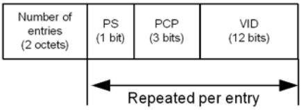
Figure 41-3—VID Filter Info format
The number of VID values in the sequence is specified by the Number of entries field.
The VID field can specify the null VID (see Table 9-2). When the null VID is specified, it is the only VID specified in the Filter Info field (i.e., the Number of entries field is assigned the value 0x0001). Use of the null VID indicates that the set of VID values associated with the VSI is supplied by the Bridge. The Bridge can obtain VID values from the VSI Type whose identity is specified by the VSI Type information in the VDP Request. The set of VID values is returned to the station via the VDP Response.
NOTE—In the case that more than one VID is assigned, the policy that determines how the VIDs are used is outside the scope of this standard.
The Filter Info field can specify the wildcard VID (see Table 9-2). When the wildcard VID is specified, it is the only VID specified in the Filter Info field (i.e., the Number of entries field is assigned the value 0x0001). Use of the wildcard VID value indicates that the VSI Type specified by the VDP Request is designated as the channel VSI Type applied to the EVB SBP associated with the S-channel.
41.2.9.2 MAC/VID Filter Info format
The MAC/VID Filter Info format indicates that the Format Info field specifies a sequence of MAC/VID value pairs to be associated with the VSI instance (41.2.7). Figure 41-4 illustrates the MAC/VID Filter Info format of the Filter Info field.
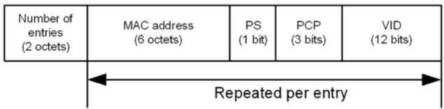
Figure 41-4—MAC/VID filter format
The number of MAC/VID pair values is specified by the field Number of Filter Info entries. Each MAC/ VID pair value carries a 6-octet individual MAC address and a 2-octet VID value.
The Filter Info field can specify the null VID for any entry. Use of the null VID indicates that the VID value is supplied by the Bridge.
41.2.9.3 GroupID/VID Filter Info format
The GroupID/VID Filter Info format indicates that the Format Info field specifies a sequence of GroupID/ VID pairs to be associated with the VSI instance (41.2.7).
Figure 41-5 illustrates the GroupID/VID Filter Info format of the Filter Info field.
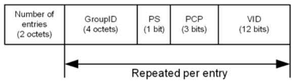
Figure 41-5—GroupID/VID filter format
The number of GroupID/VID pairs is specified by the Number of entries field.
The null VID (see Table 9-2) can be used in a GroupID/VID pair when the GroupID/VID filter format is specified in the VDP Request. In this case, the Bridge is expected to supply the corresponding local VID value in the VDP Response. For this purpose, the Bridge maintains, or has access to, the mapping between GroupID and local VID.
41.2.9.4 GroupID/MAC/VID Filter Info format
The GroupID/MAC/VID Filter Info format indicates that the Filter Info field specifies a sequence of GroupID/MAC/VID triples to be associated with the VSI instance (41.2.7). Figure 41-6 illustrates the GroupID/MAC/VID Filter Info format of the Filter Info field.
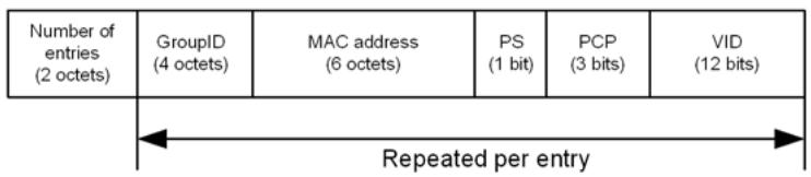
Figure 41-6—GroupID/MAC/VID filter format
The number of GroupID/MAC/VID triples is specified by the value of the Number of entries field. The null VID (see Table 9-2) can be used in a GroupID/MAC/VID triple when the GroupID/MAC/VID filter format is specified in the VDP Request. In this case, the Bridge is expected to supply the corresponding local VID value in the VDP Response. For this purpose, the Bridge maintains, or has access to, the mapping between GroupID and local VID.
41.2.10 VDP TLV type and Status semantics
The following subclauses define the semantics associated with each VDP TLV type.
41.2.10.1 Pre-Associate
The Pre-Associate TLV type is used to pre-associate a VSI instance with a Bridge Port. The Bridge validates the request (see below) and returns a failure Status in case of errors. Successful pre-association does not imply that the VSI Type will be applied to any traffic flowing through the VSI. The pre-associate enables faster response to an associate by allowing the Bridge to obtain the VSI Type prior to an association.
NOTE—If the VSI Type changes without a corresponding change to its version, then inconsistent behavior can result.
41.2.10.2 Pre-Associate with Resource Reservation
Pre-Associate with Resource Reservation involves the same steps as Pre-Associate (41.2.10.1), but on successful pre-association also reserves resources in the Bridge to prepare for a subsequent Associate request.
41.2.10.3 Associate
The Associate TLV Type creates and activates an association between a VSI instance and a Bridge Port. The Bridge allocates any required Bridge resources for the referenced VSI. The Bridge activates the configuration for the VTID. This association is then applied to the traffic flow to/from the VSI instance.
NOTE—The mechanism used by a Bridge to determine the required resources associated with a VTID is outside the scope of this standard.
For a given VSIID, a station may issue an Associate without having previously issued a Pre-Associate or Pre-Associate with Resource Reservation. During normal operations a VSI instance is associated on only one port. During network transitions (e.g., virtual station migration) a VSI instance might be associated with more than one port.
If a Pre-Associate or a Pre-Associate with Resource Reservation had previously been received for a given VSI instance, the Bridge establishes the association and allocates resources based only on the information contained in the Associate TLV. Any resources that had been reserved in order to satisfy a previous Pre-Associate with Resource Reservation, and that are not required in order to establish the association as specified in the Associate, are released.
41.2.10.4 De-Associate
The de-associate TLV Type is used to remove an association between a VSI instance and a Bridge Port. Pre-Associated and Associated VSIs can be de-associated. De-associate releases any resources that were reserved as a result of prior Associate or Pre-Associate operations for that VSI instance.
A de-associate can be initiated either by the station or the Bridge. In the latter case, the Bridge sends a deassociate TLV as if it was a response to a request from the station.
NOTE 1—A Bridge could, for example, issue a de-associate as a consequence of changes in the Bridge’s status or configuration.
NOTE 2—The result of the above semantics is that a de-associate can be initiated at any time and by either party.
41.3 Organizationally defined TLV definitions
Figure 41-7 illustrates the format of the organizationally defined TLV.
The organizationally defined TLV field definitions are contained in 41.3.3 and 41.3.4.
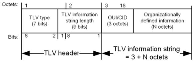
Figure 41-7—Organizationally defined TLV
41.3.1 TLV type
The TLV type field takes the value shown in Table 41-1 for the organizationally defined TLV.
41.3.2 TLV information string length
This field contains the length of the TLV information string, which is 3 + N octets, where N is the number of octets in the organizationally defined information field (41.3.4).
41.3.3 Organizationally unique identifier (OUI) or Company ID (CID)
Identifies the organization that is responsible for defining the content of the organizationally defined information field (41.3.4). The value of the OUI/CID field is an OUI (see IEEE Std 802) or a CID assigned to that organization by the IEEE registration authority.
41.3.4 Organizationally defined information
The content and interpretation of this field is specified by the organization that owns the OUI or CID value contained in the OUI/CID field (41.3.3).
41.4 Validation rules for VDP TLVs
The following rules apply to the validation of received ECPDUs that carry VDP TLVs:
a) If the first TLV in the ECPDU is not a VSI manager ID TLV (41.1), then the entire ECPDU is discarded without further processing.
b) If the ECPDU contains a TLV of a type that is not recognized by the implementation, then that TLV is discarded and is ignored by the VDP state machines.
c) If a TLV extends past the physical end of the ECPDU, then that TLV is discarded.
41.5 VDP state machines
The station VDP state machine is defined in 41.5.3. A station that supports VDP shall support one instance of the station VDP state machine for each active VSI.
The Bridge VDP state machine is defined in 41.5.2. A Bridge that supports VDP shall support one instance of the Bridge VDP state machine for each active VSI.
41.5.1 State machine conventions
The notational conventions used in the specification of VDP are as stated in Annex E.
41.5.2 Bridge VDP state machine
The Bridge VDP state machine shall implement the function defined in Figure 41-8 and the attendant definitions in 41.5.4 through 41.5.7.
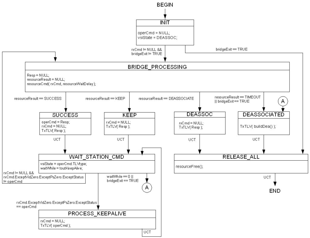
Figure 41-8—Bridge VDP state machine
41.5.3 Station VDP state machine
The station VDP state machine shall implement the function defined in Figure 41-9 and the attendant definitions in 41.5.4 through 41.5.7.
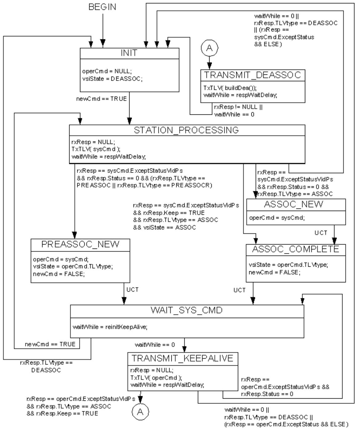
NOTE- The".Except" notation used in some exit conditions is described in 41.5.6. In this state machine,"ExceptStatus.ExceptVidZero.ExceptPsZero" has been abbreviated to "ExceptStatusVidPs".
Figure 41-9—Station VDP state machine
41.5.4 VDP state machine timers
A set of timers is used by the VDP state machines; these operate as countdown timers (i.e., they expire when their value reaches zero). These timers are 32-bit countdown timers. They
a) Have a resolution of ten microseconds, with a tolerance $0 f \pm 2 0 \%$ .
b) Are started by loading an initial integer value, n, where $0 < \mathtt { n } \le 2 ^ { 3 1 }$ .
c) Are decremented by one per timer tick, as long as $\mathbf { n } > 0 ;$ ; the interval between timer ticks is the same as the timer resolution.
d) Represent the remaining time in the period.
NOTE—Where timers are used in the VDP state machines to initiate keep-alive messages, it is recommended that a small random component is added to the timer interval in order to avoid the possibility that timers associated with different VSIs become synchronized.
41.5.4.1 waitWhile
An instance of the waitWhile timer exists for each instance of the station VDP state machine (41.5.3) and for each instance of the Bridge VDP state machine (41.5.2).
41.5.5 VDP state machine variables and parameters
41.5.5.1 bridgeExit
A Boolean signal from the Bridge. When TRUE, this variable indicates that the Bridge VDP state machine should exit.
41.5.5.2 newCmd
This variable is set to TRUE by the system to indicate to the state machine that there is a command ready to be transmitted. The state machine sets newCmd FALSE when that command has been processed and is ready to process a further command.
41.5.5.3 NULL
A null value. If NULL is assigned to a TLV variable, it indicates that the variable contains no TLV.
41.5.5.4 operCmd
The command TLV (the TLV that carried the current operating command—associate, pre-associate, or deassociate), at the station or Bridge, or NULL if there is no current operating command.
41.5.5.5 reinitKeepAlive
The value used to initialize the waitWhile timer (41.5.4.1) by the station VDP state machine in order to determine when to transmit a keep alive message. This value is derived from the value of the management variable urpVdpOperReinitKeepAlive (12.26.5), which is type timer exp, by using urpVdpOperReinitKeepAlive as an exponent of 2. The variable urpVdpOperReinitKeepAlive is the larger of the values proposed by the station and Bridge.
The default value used by the station for urpVdpOperReinitKeepAlive is an exponent value of 20, representing a timer interval of about 10.5 s.
41.5.5.6 resourceCmdResult
This variable is used to record the result of a resourceCmd() procedure call (41.5.7.2). The possible result values are as follows:
a) Success
b) timeOut
c) Fail (insufficient resources)
d) Fail (invalid format)
e) Fail (other)
41.5.5.7 resourceWaitDelay
The value used to initialize the waitWhile timer (41.5.4.1) by the Bridge VDP state machine when the state machine is waiting for a response. This value is derived from the values of the management variable sbpVdpOperRsrcWaitDelay (12.26.2), which is type timer exp, by using sbpVdpOperRsrcWaitDelay as an exponent of 2. The variable sbpVdpOperRsrcWaitDelay is the larger of the values proposed by the EVB station and EVB Bridge.
The default value used by the station and Bridge for sbpVdpOperRsrcWaitDelay is an exponent value of 20, representing a timer interval of about 10.5 s.
41.5.5.8 Resp
A response TLV returned from the procedure resourceCmd() (41.5.7.2). Resp can be set to NULL prior to issuing resourceCmd(). The variable is always non-NULL when resoureCmd() completes.
41.5.5.9 respWaitDelay
The value used to initialize the waitWhile timer (41.5.4.1) by the station VDP state machine when the state machine is waiting for a response. This value is derived from the values of the management variables urpVdpOperRsrcWaitDelay (12.26.5), ecpOperAckTimerInit (12.27) and ecpOperMaxRetries (12.27). The value is expressed in units of VDP timer tics of 10 usec by the following equation:
$$
\text { respWaitDelay } = 1. 5 \times (2 ^ {\text { urpVdpOperRsrcWaitDelay }} + (2 + 2 \times \text { maxRetries } + 1) \times \text { ackTimerInit })
$$
NOTE 1—The factor of 1.5 allows for a 20% tolerance in the timer values.
Where maxRetries is the ECP state machine variable which is ecpVdpOperMaxRetries and ackTimerInit is the ECP state machine variable which is 2ecpOperAckTimerInit. The values of urpVdpOperRscWaitDelay, ecpOperAckTimerInit, and ecpOperMaxRetries that are used are the larger of the values proposed by the station and Bridge.
The default value used by the station and Bridge is about 17.4 s. The default value for urpVdpOperRscWaitDelay is an exponent of 20 representing a timer interval of about 10.5 s and for ecpOperAckTimerInit is an exponent of 14 representing a timer interval of about 164 ms. The default value of the ECP state machine variable ackTimerInit is 16,384 ECP/VDP timer tics. The default value for ecpOperMaxRetries and the ECP state machine variable maxRetries is 3.
NOTE 2—The factor of 1.5 allows for a 20% tolerance in the timer values.
41.5.5.10 rxCmd
The last received command TLV, or NULL if no command TLV has been received. The rxCmd variable is updated only if it is NULL.
41.5.5.11 rxResp
The last received response TLV. The rxResp variable contains the last received Resp TLV at the station or NULL. RxResp is NULL if no TLVs have been received or if the variable has been cleared by the state machine.
NOTE—It is possible to have a race condition when clearing rxResp since it can be updated asynchronously if the Bridge issues an unsolicited DEASSOC command. If the race condition occurs, the de-associate will occur as a result of the station timer expiring.
41.5.5.12 sysCmd
A command TLV from the system or hypervisor, or NULL if there is no pending command. The VDP state machine is ready to accept a new command when the value of sysCmd is NULL.
41.5.5.13 toutKeepAlive
The value used to initialize the waitWhile timer (41.5.4.1) by the Bridge VDP state machine in order to determine when to expect to receive a keep alive message. This variable is derived from the values of the management variables sbpVdpOperReinitKeepAlive (12.26.2), ecpOperAckTimerInit (12.27), and ecpOperMaxRetries (12.27). The value is expressed in units of VDP timer tics of 10 usec by the following equation:
$$
\text { toutKeepAlive } = 1. 5 \times (2 ^ {\text { sbpVdpOperReinitKeepAlive }} + (2 + 2 \times \text { maxRetries } + 1) \times \text { ackTimerInit })
$$
NOTE—The factor of 1.5 allows for a 20% tolerance in the timer values.
Where maxRetries is the ECP state machine variable which is ecpVdpOperMaxRetries and ackTimerInit is the ECP state machine variable which is 2ecpOperAckTimerInit. The values of sbpVdpOperReinitKeepAlive, ecpOperAckTimerInit, and ecpOperMaxRetries that are used are the larger of the values proposed by the EVB station and EVB Bridge.
The default value used by the station and Bridge is about 17.4 s. The default for sbpVdpOperReinitKeepAlive is an exponent of 20 representing a timer interval of about 10.5 s and for ecpOperAckTimerInit is an exponent of 14 representing a timer interval of about 164 ms. The default value of the ECP state machine variable ackTimerInit is 16,384 ECP/VDP timer tics. The default value for ecpOperMaxRetries and the ECP state machine variable maxRetries is 3.
41.5.5.14 vsiState
The current association state of the VDP state machine. This variable may take the values DEASSOC (deassociated), PREASSOC (pre-associated), PREASSOCR (pre-associated with resource reservation), or ASSOC (associated).
41.5.6 Command-Response TLV field references in state machines
The state machines can make use of the value of individual fields within the value of a TLV by using the following notation:
Tlv-variable-name.Field-name
In practice, only the following two Field-names are used in the state machines:
a) TLVtype, which references the TLV type field of the TLV (41.2.1); and
b) Keep, which references the Keep bit of the Status field in the TLV (41.2.3).
So, for example, a reference in the state diagram to sysCmd.Keep is a reference to the Keep bit of the Status field of the TLV value contained in the sysCmd variable.
The state machines also make use of the ability to compare TLV values for equality or inequality while ignoring a specific field, using the following notation:
Tlv-variable-name.ExceptField-name
This is interpreted as meaning “The value of the TLV contained in the Tlv-variable-name variable, ignoring the value of Field-Name in the comparison.”
The reserved Field-name “VidZero” is used to specify that if any VID in the Filter Info field (41.2.9.1) contains zero, then that VID is ignored in the comparison. The reserved Field-name “PsZero” is used to specify that if PS in the Filter Info field contains zero, then the PS and PCP are both ignored in the comparison.
Multiple fields can be excepted by concatenating ExceptField-name items with a separating period.
The value of the Flag bits (Table 41-2 and Table 41-4) are always ignored in field comparison operations.
41.5.7 VDP state machine procedures
41.5.7.1 buildDea()
The buildDea() procedure builds a DEASSOCIATE TLV for the VSI as the return parameter.
41.5.7.2 resourceCmd(rxCmd, delay)
This procedure makes a resource request from the Bridge, waits for a response, builds a response TLV and places it in the variable Resp. The response values reflect the requested resource action (PREASSOC, ASSOC, or DEASSOC), conditioned by return variable resourceResult, which is set to NULL before calling the resourceCmd procedure and set to one of the following values by the procedure:
a) SUCCESS
b) KEEP
c) DEASSOCIATE
d) TIMEOUT
The response constructed by the procedure in the Resp variable can be PREASSOC, ASSOC, or DEASSOC with a Status, keep indicator and hard error indicator. For a successful completion the procedure will copy the rxCmd parameter into the Resp variable. If the Bridge is selecting VIDs based on GroupIDs, then the procedure also replaces zero VIDs with valid VIDs.
The delay parameter specifies how long the procedure should wait for a response. If the delay is exceeded, no response is received, and the VSI is not associated, then the procedure returns a value of TIMEOUT. If the delay is exceeded, no response is received and the VSI is associated, then the procedure returns a value of KEEP along with a Resp equal to the rxCmd parameter. If the delay is not exceeded, then the procedure returns SUCCESS, KEEP, or DEASSOCIATE depending on the response received along with the rxCmd in the Resp and the Status set as follows:
e) DEASSOC:
The procedure returns DEASSOCIATE along with Resp.Status set to Success.
f) PREASSOC:
1) If the request can be satisfied, the procedure returns SUCCESS along with Resp.Status set to Success.
2) If the request cannot be satisfied, the procedure returns DEASSOCIATE along with Resp.Status set to a code other than Success and the Resp.hard set to TRUE if a retry will not change the situation or FALSE if a retry might change the situation.
g) PREASSOCR:
1) If the request can be satisfied, and the resources requested are available and reserved for this VSI, the procedure returns SUCCESS along with the Resp.Status set to Success.
2) If the request cannot be satisfied, or the resources are unavailable or not reserved for this VSI, the procedure returns DEASSOCIATE along with the Resp.Status code other than Success and the Resp.hard set to TRUE if a retry will not change the situation or FALSE if a retry might change the situation.
h) ASSOC:
1) If the request can be satisfied, and the resources requested are available and enabled for this VSI, the procedure returns SUCCESS along with the Resp.Status set to Success.
2) If the request cannot be satisfied, or the resources are unavailable or not reserved for this VSI, and the VSI is not currently Associated, the procedure returns DEASSOCIATE along with the Resp.Status code other than Success and the Resp.hard set to TRUE if a retry will not change the situation or FALSE if a retry might change the situation.
3) If the request cannot be satisfied, or the resources are unavailable or not reserved for this VSI, and the VSI is currently Associated, the procedure returns KEEP along with the Resp.Status code other than Success and the Resp.hard set to TRUE if a retry will not change the situation or FALSE if a retry might change the situation.
NOTE—A de-associate can happen at any time, initiated by either party to an association.
41.5.7.3 resourceFree()
The resourceFree() procedure frees all resources associated with this VSI.
41.5.7.4 TxTlv(tlv)
The TxTlv() procedure causes the TLV passed in the tlv parameter to be transmitted.
42 S-Channel Discovery and Configuration Protocol (CDCP)
This clause provides an overview, detailed semantics, and state machines for CDCP.
42.1 CDCP discovery and configuration
CDCP is used to configure S-channels (see 40.2). S-channels are implemented in stations and Bridges using a Port-mapping S-VLAN component (22.6.4). Figure 40-1 illustrates the use of S-channels.
When the Port-mapping S-VLAN components used to create S-channels exist, they can exchange un-Stagged frames that are assigned to S-VID 1 and are considered to be assigned to the default S-channel, which has an S-channel Identifier (SCID) of 1. The default S-channel is always un-S-tagged even when S-channels are enabled.
NOTE 1—SCIDs are locally assigned identifiers.
The S-channel configuration is determined by the Bridge’s capabilities and by requests made using CDCP described in this clause. The station requests S-channels using CDCP. CDCP in turn uses an LLDP TLV exchange to coordinate the creation and deletion of S-channels. The LLDP database used by CDCP is addressed using the Nearest non-TPMR Bridge address. The Port-mapping S-VLAN component filters both the Nearest Bridge and the Nearest non-TPMR Bridge addresses on all ports and passes the Nearest Customer Bridge address.
The SCID value 1 and S-VID value 1 are always reserved for the exclusive use as the un-S-tagged default Schannel. CDCP reports the default S-channel in the CDCP TLV as the first SCID, S-VID pair (i.e., <1,1>). The Bridge shall not assign this S-VID except to the default S-channel.
NOTE 2—For the default S-channel, any QoS information that is necessary is extracted from the PCP bits of the C-tag.
42.2 CDCP state machine overview
CDCP requires each side of the configuration be assigned a role as a Bridge or a station. This is done by setting the AdminRole variable. In most cases the station or Bridge role will not be settable, though the protocol allows for systems that can take either role. For CDCP to configure an S-channel, one side takes the station role and the other side takes the Bridge role. If both sides of the LAN have equipment configured as stations or as Bridges the protocol will not configure S-channels.
NOTE—The role adopted by a given system can be fixed if the system is only capable of operating in a given role.
The CDCP state machine (Figure 42-1) operates on data contained in LLDP MIBs that is updated as a result of the reception of CDCP TLVs, exchanged using LLDP operating on the Nearest non-TMPR Bridge address. The structure of CDCP TLVs is defined in D.2.14.
The configuration proceeds by the Bridge providing the best match it can to the station’s requested channels and configuration. The station makes the resource request, the Bridge responds with its best matching resources, the station then goes operational and reports its running configuration to the Bridge, and finally the Bridge goes operational with the running configuration of the station.
In the event the station wishes to change its configuration it alters the request in its CDCP TLV and then follows the same process as previously stated. If the ‘B’ loses its ability to support the current configuration it can alter the current configuration in its CDCP TLV at which time the station drops down to the resources supplied by the Bridge.
42.3 CDCP configuration state machine
The notational conventions used in the specification of CDCP are as stated in Annex E.
In an implementation that supports the station role, the CDCP configuration state machine shall implement the function specified by the state diagram in Figure 42-1 and the attendant definitions in 42.4 and 42.5.
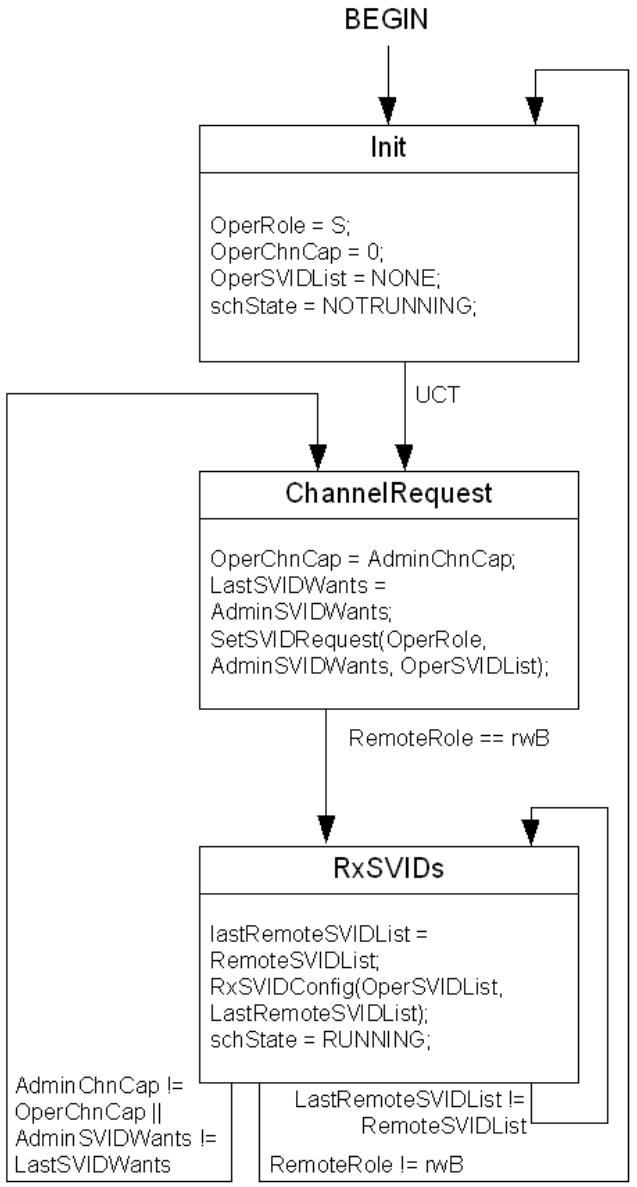
Figure 42-1—CDCP state machine—Station role
In an implementation that supports the Bridge role, the CDCP configuration state machine shall implement the function specified by the state diagram in Figure 42-2 and the attendant definitions in 42.4 and 42.5.
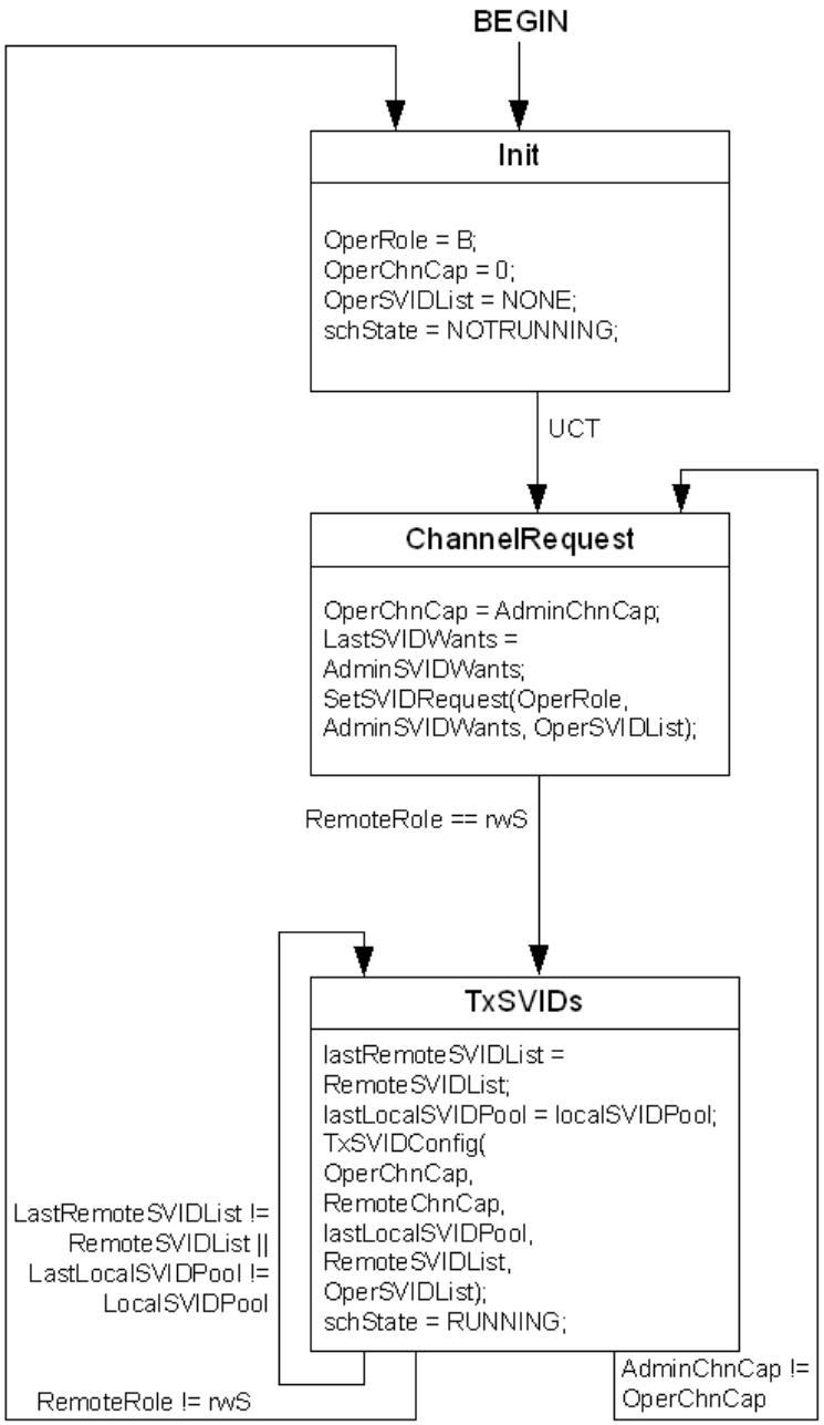
Figure 42-2—CDCP state machine—Bridge role
42.4 CDCP configuration variables
42.4.1 AdminChnCap
The administratively configured value for the Number of Channels supported parameter. This value is included as the ChnCap parameter in the CDCP TLV.
42.4.2 AdminRole
The administratively configured value for the local port’s role parameter. The value of AdminRole is not reflected in the CDCP TLV. The AdminRole can take the value S or B; the value determines which of the CDCP state machines is instantiated. If AdminRole is S, the Station role state machine (42-1) is instantiated. If AdminRole is B, the Bridge role state machine (42-2) is instantiated. S indicates the sender is unwilling to accept S-channels configuration (mode, number of channels supported, channel index) from its neighbor and that the sender is willing to accept S-VID assignments from the neighbor. Stations usually take the S role. B indicates the sender is willing to accept S-channels configuration (mode, number of channels supported, channel index) from its neighbor and that the sender is willing do the best it can to fill the S-VID requests from the neighbor. Bridges usually take the B role.
42.4.3 AdminSVIDWants
The administratively configured value for (SCID, S-VID) pairs wanted by a station; it is not used by a Bridge. The first value is always the pair (1, 1) for the default S-channel assignment. The S-channel numbers may be any valid number in the range 0–167. A 0 S-channel number indicates reserved space in the TLV. If the S-VID value is 0 it means the station is requesting any available S-VID. S-VID value 1 is reserved for exclusive use for the default S-channel S-VID. No other values of the SVID are permitted. The AdminSVIDWants parameter is used to form the (SCID, S-VID) pairs in the CDCP TLV. This list is formed from the EVB station’s S-channel interface table (12.26.4) and is used to build the EVB Bridge’s S-channel interface table.
42.4.4 LastLocalSVIDPool
A temporary copy of the LocalSVIDPool.
42.4.5 LastRemoteSVIDList
Temporary local copy of the RemoteSVIDList. This variable is not included in the CDCP TLV. The LastRemoteSVIDList has the same syntax as RemoteSVIDList.
42.4.6 LastSVIDWants
A local temporary copy of the AdminSVIDWants.
42.4.7 LocalSVIDPool
The set of S-VIDs and Bridge Ports available for S-channel assignment. These are determined by both administrative resource assignments and by resource availability. The OperSVIDList for a B role is drawn from the LocalSVIDPool.
42.4.8 OperChnCap
The current value for the ChnCap parameter. This value is included as the ChnCap parameter in the local CDCP TLV. The range for this variable is 1–167.
42.4.9 OperRole
The current operational value of the Role parameter in the local port. This value is included as the Role parameter in the CDCP TLV and may take values S or B as described for AdminRole.
42.4.10 OperSVIDList
The current value for (SCID, S-VID) assignments. This is the list of (SCID, S-VID) pairs included in the local CDCP TLV. The total size of the list cannot exceed 167 pairs. The list always includes the default S-channel pair (1,1).The valid range for each S-channel of this list is from 1–167. The valid range for each S-VID in the list is from 0 to 0xffe. For the S role a S-VID of 0 indicates a request for a channel. For the B role an S-VID of 0 indicates a non-configured channel.
42.4.11 RemoteChnCap
The current value for the ChnCap parameter. This value is included as the ChnCap parameter in the remote CDCP TLV. NULL means no remote CDCP TLV exists in the local LLDP database. The range for this variable is 1–167.
42.4.12 RemoteRole
Indicates the value in the remote CDCP TLV role field. rrNull indicates either the TLV was not present in the last LLDP PDU or that no LLDP PDUs have been received. rwS and rwB indicate that the Role field was set in the CDCP TLV received and that it had a value of S or B, respectively, as described for the AdminRole variable.
42.4.13 RemoteSVIDList
The current value for (SCID, S-VID) assignments. This is the list of (SCID, S-VID) pairs included in the remote CDCP TLV. NULL means no remote CDCP TLV exists in the local LLDP database. If the list is empty but the CDCP TLV is present, its value is NONE. The total size of the list cannot exceed 167 pairs. The valid range for each S-channel of this list is from 1–167. The valid range for each S-VID in the list is from 0 to 0xffe. When the S-VID is value is 0 the S-VID is not configured. For the S role, a S-VID of 0 indicates a request for a channel. For the B role, an S-VID of 0 indicates a non-configured channel. The RemoteSVIDList is reflected within the EVB Bridge in the S-channel interface table (12.26.4).
42.4.14 schState
The current running state of the S-channel. The values for this variable are NOTRUNNING or RUNNING. This variable can be read using the management functionality defined in Clause 12.
42.5 CDCP configuration procedures
42.5.1 SetSVIDRequest (OperRole, AdminSVIDWants, OperSVIDList)
This function creates the OperSVIDList placed in the Local LLDP database, as follows:
a) If the OperRole for the equipment is B, then the OperSVIDList remains unchanged.
If the OperRole for the equipment is S, the function compares the AdminSVIDWants with the OperSVIDList and amends the OperSVIDList, as follows:
1) All active S-channels in the OperSVIDList that are in the AdminSVIDWants are kept active, and in addition, any channels not currently in the OperSVIDList are requested by including them in the OperSVIDList along with a 0 S-VID number. The OperSVIDList S-channel order is changed to match the AdminSVIDWants.
2) Any S-channels in the OperSVIDList that are not in AdminSVIDWants are made inactive and are removed from the OperSVIDList.
42.5.2 RxSVIDConfig (OperSVIDList, LastRemoteSVIDList)
This function creates the OperSVIDList placed in the Local LLDP database for an S role port.
The function compares the AdminSVIDWants with the LastRemoteSVIDList. For each AdminSVIDWants S-channel with an S-VID assignment in the LastRemoteSVIDList, a (SCID, S-VID) pair is generated in the OperSVIDList. For each AdminSVIDWants S-channel without an S-VID assignment in the LastRemoteSVIDList, a (SCID,0) pair is generated in the OperSVIDList. The OperSVIDList S-channel order is set to match the AdminSVIDWants.
42.5.3 TxSVIDConfig (OperChnCap, RemoteChnCap, LastLocalSVIDPool, RemoteSVIDList, OperSVIDList)
This function creates the OperSVIDList placed in the Local LLDP database for a B role port.
First the function takes the smaller of the OperChnCap and RemoteChnCap and truncates the RemoteSVIDList to the smaller of the two.
A new OperSVIDList is created as follows:
a) For each S-channel in the RemoteSVIDList with a (SCID, S-VID) pair in the OperSVIDList, the (SCID, S-VID) remains unchanged unless the S-VID is no longer part of the LastLocalSVIDPool. If the S-VID is no longer in the pool, a new one is selected if available. If no S-VID is available, the (SCID, S-VID) pair will be deleted from the OperSVIDList.
b) For each S-channel in the OperSVIDList without a (SCID, SVID) pair in the RemoteSVIDList, the (SCID, SVID) pair will be deleted from the OperSVIDList.
c) For a (SCID, SVID) pair in the remote list, where the S-VID is zero, an S-VID is assigned if it is available and the pair is inserted in the OperSVIDList. If an S-VID is not available, the pair is not inserted in the OperSVIDList.
d) For a (SCID, SVID) pair in the remote list, where the S-VID is nonzero, there is no effect on the OperSVIDList.
43 Edge Control Protocol (ECP)
This clause provides an overview, detailed semantics, and state machines for ECP.
43.1 ECP operation
Figure 43-1 depicts, at a high level, ECP operation. In step 1, the upper layer protocol (ULP) passes an outgoing ULP Data Unit (ULPDU) to ECP by invoking a transmit request procedure. In step 2, the ULPDU, which for some ULPs (e.g., VDP) may contain a set of ULP TLVs, is transmitted and an ECP low-level acknowledgment (ACK) timer is set. The frame is not yet deleted from the transmit buffer until an ACK (L-ACK in the diagram) is received for that ECPDU. In step 3, the arriving ECP frame is received into a receive buffer, where it is held until it is removed by an ECP indication procedure that passes the ULP Data Unit to the associated upper-level protocol. In step 4, when the receive buffer is emptied, a L-ACK is sent to the sender. In step 5, if the L-ACK is received before the L-ACK timer expires, then the transmit buffer is cleared and ECP can process another ULPDU through the ECP procedure. However, if the L-ACK timer expires before the L-ACK is received, then the frame in the transmit buffer is re-sent and the L-ACK timer is re-initialized. This timeout and re-sending can occur up to a maximum number of retries determined by the value of the maxRetries parameter of the transmit state machine. If this number of retries is reached and there is still no response, then the transmit buffer is cleared, a failure counter is incremented, and the transmit state machine is then ready to process another ULPDU. There is no indication to the ULP that a transmission failure has occurred; it is the ULP’s responsibility both to detect the failure condition and to recover from it in an appropriate way.
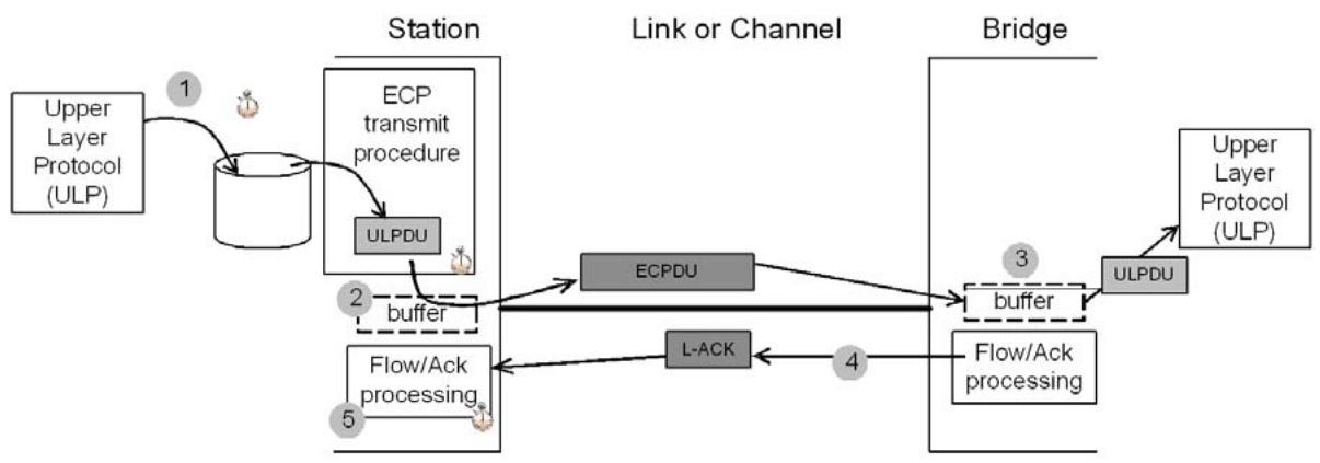
Figure 43-1—Example ECP exchange
ECP is intended to operate between two peers over an IEEE 802 LAN. ECP delivers the following service characteristics:
a) Reliable delivery of ULPDUs, resilient against frame loss. The value of the maxRetries parameter determines the number of sequential lost frames that the protocol can sustain.
b) Delivery of ULPDUs to the recipient ULP in the order that they were transmitted by the sending ULP.
c) Delivery of a single copy of each ULPDU to the recipient.
d) Flow control that provides protection against buffer overrun on the receive side.
43.2 Edge Control Sublayer Service (ECSS)
Two service primitives model the hand-off of data units between the ULP and ECP: ECP_UNITDATA.request and ECP_UNITDATA.indication.
ECP_UNITDATA.request (ulptype, ulpdu)
The ECP_UNITDATA.request primitive is invoked by the ULP to notify ECP that a ULPDU is ready to be transmitted. The ulpdu parameter is the ULPDU that the ULP wishes to transmit. The ulptype parameter identifies the type of the ULP (see 43.3.3).
NOTE—For example, for VDP the ULPDU consists of a set of VDP TLVs passed to ECP for transmission. The maximum size of the ULPDU, and therefore the set of TLVs that it can contain, is determined by the maximum SDU size supported by the underlying MAC (see 6.5.8).
ECP_UNITDATA.indication (ulptype, ulpdu)
The ECP_UNITDATA.indication is invoked by ECP to indicate a ULPDU has been received and is available for ULP processing. The ulpdu parameter is the ULPDU that has been received. The ulptype parameter identifies the type of the ULP, as indicated in the received ECPDU (see 43.3.3).
43.3 ECP state machines
43.3.1 State machine conventions
The notational conventions used in the specification of ECP are as stated in Annex E.
43.3.2 Overview
There are two state machines used by each ECP instance: the ECP transmit state machine (43.3.4) and the ECP receive state machine (43.3.5). A Bridge Port that supports ECP shall support one instance of the ECP transmit state machine and one instance of the ECP receive state machine.
Initialization of the transmit and receive state machines occurs when portEnabled (43.3.7.5) is FALSE, or when a BEGIN global event occurs. The transmit state machine transmits an ECPDU in response to an ECP_UNITDATA.request from the ULP that indicates there is a PDU ready to be transmitted. The PDU is transmitted with a sequence number that is used by the (remote) receive state machine in a responding ACK ECPDU. If no ACK with the correct sequence number is received within a defined time period, and if the maximum number of retries has not been reached, the transmit state machine retransmits the ECPDU. If the maximum number of retries is exceeded, or if an ACK is received that matches the last sequence number sent, then the transmit state machine increments the sequence number and waits for the next ECP_UNITDATA.request.
NOTE—The sequence number for the first ECPDU transmitted after a state machine initialization (which occurs when BEGIN is TRUE or portEnabled [43.3.7.5] is FALSE) is an implementation choice; for example, it could be a predetermined number, a random number, or it could continue the sequence from the last sequence number used.
When the first ECPDU is received following initialization, the receive state machine initializes its local record of the last sequence number received to be one less than the sequence number in the received ECPDU. This record of the last sequence number received allows the state machine to detect whether the received ECPDU has been received already (current and last sequence numbers match) or this is a new ECPDU (current and last sequence numbers differ). In both cases, the receive state machine sends an ACK ECPDU, using the current sequence number. In the case that the received ECPDU is new, the last received sequence number is updated to reflect the sequence number of the received ECPDU, and an ECP_UNITDATA.indication is sent to the ULP to pass the contents of the ECPDU to the service user.
43.3.3 Edge Control Protocol Data Unit (ECPDU)
This subclause specifies the format of a ECPDU, along with the header that is added to and removed from ECP frames by the ECP function. The ECP header allows each ECPDU from the sender to be identified through a sequence number, which the receiver acknowledges by sending a ECP Acknowledgment frame. The format of the ECPDU is illustrated in Figure 43-2.
<table><tr><td>Octets:</td><td>1</td><td>2</td><td colspan="2">3</td><td>4</td><td>5</td><td>6</td><td>7</td><td>7+N</td></tr><tr><td></td><td colspan="2">EtherType (2 octets)</td><td>Version (4 bits)</td><td>Operation type (2 bits)</td><td>Subtype (10 bits)</td><td colspan="2">Sequence Number (2 octets)</td><td colspan="2">ULPDU (N octets, optional)</td></tr><tr><td>Bits:</td><td colspan="2"></td><td>8</td><td>4</td><td>2</td><td>8</td><td>1</td><td colspan="2"></td></tr></table>
Figure 43-2—ECPDU structure
The destination address of the Ethernet frame that contains a ECPDU is specified by the ULP. The address used is either an individual MAC address or one of the reserved addresses specified in Table 8-1.
The source address shall be the individual MAC address of the sending station or port.
The fields of the ECPDU are defined in the following subclauses.
43.3.3.1 EtherType
A 16-bit field that contains the EtherType assigned for use by ECP (89-40).
43.3.3.2 Version
A 4-bit field that identifies the protocol version. The version shall be 0x01.
43.3.3.3 Operation type
A 2-bit field that identifies the operation type as follows:
a) ECP request (0x0).
b) ECP acknowledgment (0x1).
43.3.3.4 Subtype
A 10-bit field that defines the ULP type included in the PDU. For ACKs the subtype is ignored at the station. The subtype used by VDP is as shown in Table 43-1.
Table 43-1—ECP subtypes
<table><tr><td>Use</td><td>Reference</td><td>Subtype</td></tr><tr><td>VDP</td><td>Clause 41</td><td>0x0001</td></tr><tr><td>Port Extender Control and StatusProtocol (PE CSP)</td><td>IEEE Std 802.1BR</td><td>0x0002</td></tr><tr><td>Reserved for future standardization</td><td></td><td>All other values</td></tr></table>
43.3.3.5 Sequence Number
A 2-octet field that identifies the sequential order of the PDU, with respect to other ECPDUs. The starting sequence number can start anywhere for the first ECPDU, but the sequence number for each subsequent new request ECPDU is incremented by 1 modulo 65536.
NOTE—The sequence numbers used by each instance of the ECP transmit state machine are independent of each other.
43.3.3.6 ULPDU
This field contains an upper layer protocol data unit (ULPDU) if the operation type in the Mode field is ECP request; the field is absent if the operation type is ECP acknowledgment.
43.3.4 ECP transmit state machine
The ECP transmit state machine shall implement the function specified by the state diagram in Figure 43-3 and the attendant definitions in 43.3.6 through 43.3.8.
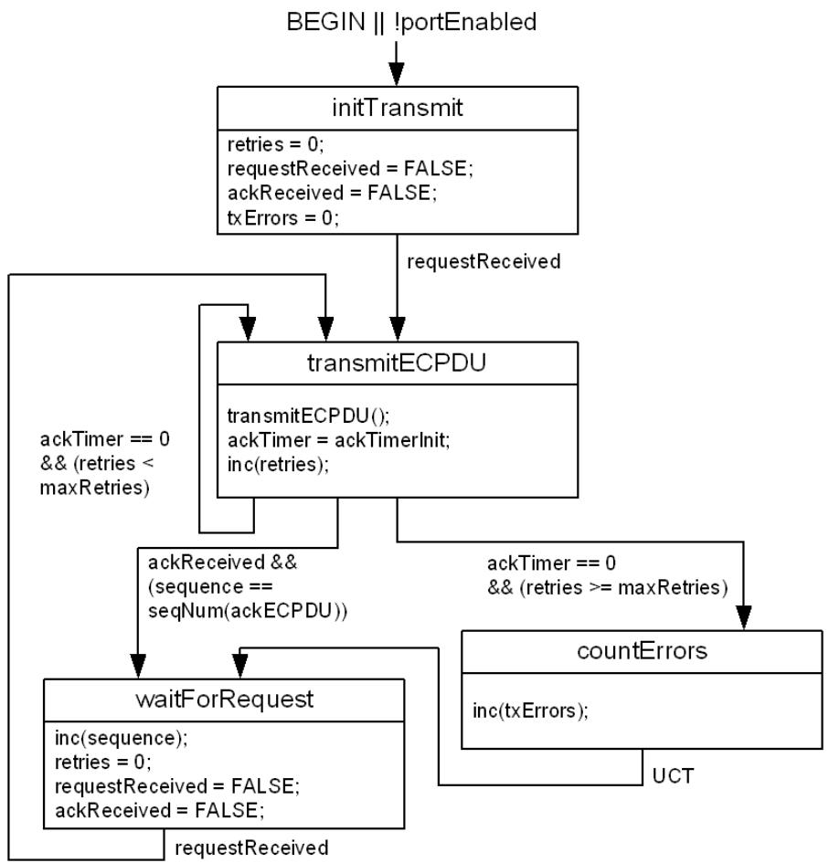
Figure 43-3—ECP transmit state machine
43.3.5 ECP receive state machine
The ECP receive state machine shall implement the function specified by the state diagram in Figure 43-4 and the attendant definitions in 43.3.6 through 43.3.8.
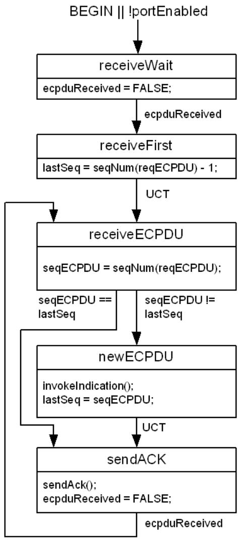
Figure 43-4—ECP receive state machine
43.3.6 ECP state machine timers
A set of timers is used by the ECP state machines; these operate as countdown timers (i.e., they expire when their value reaches zero). These timers are based on the Timer Exp data type (12.3). They
a) Have a resolution of ten microseconds, with a tolerance $0 f \pm 2 0 \%$ .
b) Are started by loading an initial integer value, n, where $0 < \mathtt { n } \le 2 ^ { 3 1 }$ .
c) Are decremented by one per timer tick, as long as $\mathbf { n } > 0 ;$ ; the interval between timer ticks is the same as the timer resolution.
d) Represent the remaining time in the period.
43.3.6.1 ackTimer
The ackTimer is used to determine how long the transmit state machine will wait for an acknowledgment PDU to be received before it either retries a transmission or aborts a transmission due to too many retries. This timer is initialized using the value of ackTimerInit determined as stated in D.2.13.6.
43.3.7 ECP state machine variables and parameters
43.3.7.1 ackReceived
This Boolean variable is set to TRUE when an ECPDU is received with a MODE field indicating that the PDU is an ACK. The variable is set FALSE by the ECP transmit state machine once the ACK has been processed.
43.3.7.2 ecpduReceived
This Boolean variable is set to TRUE when an ECPDU is received with a MODE field indicating that the PDU is a request. The variable is set FALSE by the ECP receive state machine once the request has been processed and the ACK has been sent.
43.3.7.3 lastSeq
This integer variable is used to record the previous received sequence number.
43.3.7.4 maxRetries
This integer variable defines the maximum number of times that the ECP transmit state machine will retry a transmission if no ACK is received. The default value of maxRetries is 3; this variable can be changed by management as documented in 12.26.2. The value is derived from ecpOperMaxRetries, Table 12-26.
43.3.7.5 portEnabled
This Boolean variable is set to the value of the MAC_Operational parameter (IEEE Std 802.1AC) for the Port.
43.3.7.6 requestReceived
This Boolean variable is set to TRUE when a ULP issues an ECP_UNITDATA.request primitive. The variable is set FALSE by the state machine once the request has been processed.
43.3.7.7 retries
This integer variable counts the number of transmission retries that have been made for the current ECPDU.
43.3.7.8 seqECPDU
This integer variable is used to record the sequence number contained in the most recent received request ECPDU.
43.3.7.9 sequence
This integer variable is used to record the current sequence number that is used in transmitted request ECPDUs.
43.3.7.10 txErrors
This integer variable is used to count the number of times that the ECP transmit state machine has retransmitted an ECPDU.
43.3.8 ECP state machine procedures
43.3.8.1 inc(counter)
This procedure increments the counter variable by 1 modulo 65536.
43.3.8.2 transmitECPDU()
This procedure causes an ECPDU to be transmitted, using the PDU structure defined in 43.3.3. The sequence number field is set to the least significant 16 bits of the current sequence number contained in the sequence variable (43.3.7.9). The mode field is set to ECP request. The ULPDU field is set to the value of the ulpdu parameter of the request primitive. The subtype field is set to the value of the ulptype parameter of the request primitive.
43.3.8.3 invokeIndication()
This procedure causes an ECP_UNITDATA.indication primitive to be invoked in order to pass the contents of an incoming ECPDU to the ECP service user. The ulptype parameter carries the value of the ULP type carried in the ECPDU. The ulpdu parameter carries the value of the ULPDU field of the ECPDU.
43.3.8.4 sendAck()
This procedure causes an ECPDU to be transmitted, using the PDU structure defined in 43.3.3. The sequence number field is set to the least significant 16 bits of the sequence number contained in the seqECPDU variable (43.3.7.8). The mode field is set to ECP acknowledgment. The ULPDU field is absent. The subtype field is set to the value of the ulptype parameter of the received request ECPDU.
43.3.8.5 seqNum(pdu-type)
This procedure returns an integer value equal to the value of the most recently received request ECPDU (pdu-type = reqECPDU) or acknowledgment ECPDU (pdu-type = ackECPDU).
44 Equal Cost Multiple Paths (ECMP)
SPB supports two approaches to spreading traffic load. The first approach, ECT VLANs, spreads traffic by assigning each service instance to a VLAN configured to use one of the supported SPT Sets. This approach is applicable to both SPBV and SPBM. Each Base VID is assigned to an ECT-ALGORITHM (tie-breaker) that defines the SPT Set for that VLAN, and different ECT Algorithms may thus be used to select different shortest paths in the SPT Region. In case of a PBBN, each I-SID is assigned to a Base VID. This approach can spread traffic load while maintaining traffic path congruence in each VLAN.
The second approach, ECMP, spreads traffic by employing multiple equal cost paths with a single VID. This approach is applicable only to SPBM. Unicast frame filtering dynamically selects a next hop from the set of equal cost next hops for the frame’s destination MAC address. Multicast frame filtering is controlled by selecting a multicast routing mode and a tie-break mask for each backbone service instance and advertising that selection in ISIS-SPB. Multicast filtering entries for the backbone service instance are generated by calculations that select a multicast tree from the set of Equal Cost Trees (ECTs) in the SPT Region based on the advertised multicast mode and tie-break mask.
44.1 SPBM ECMP
44.1.1 ECMP Operation
SPBM ECMP provides a mechanism to spread traffic load across a set of equal cost shortest paths in an SPT Region using a single VID. Rather than using one equal cost tie-breaking function to create a single SPT for all individual addresses, ECMP uses a hash function to spread individual address forwarding over a set of equal cost forwarding ports.
If flow filtering (44.2) is not supported, the ECMP ECT Algorithm selects one port from the set of equal cost forwarding ports for each individual address (44.1.2) and creates a Dynamic Filtering Entry for the address indicating the selected port.
If flow filtering (44.2) is supported, a set of equal cost forwarding ports may be recorded in the FDB in a Dynamic Filtering Entry (8.8.3). During unicast frame filtering the MAC Relay Entity selects one forwarding port from the applicable set using a dynamic port selection process (44.2.3).
The individual address forwarding port selection processes, both with and without flow filtering, are designed to
a) Spread traffic (i.e., make varied choices) for different flows traversing the SPT Region, and
b) Maintain frame ordering for each flow by making the same choice for all frames belonging to any single flow.
ECMP is supported by Dynamic Filtering Entries in the FDB and, optionally, the flow filtering tag (F-TAG, 44.2.1) that carries Flow Hash and TTL information. The flow hash serves both to distinguish frames belonging to different flows and to identify frames that belong to (or may belong to) the same flow. The flow hash is used as input to the dynamic port selection process to support the design goals noted above. The TTL is used to mitigate traffic loops, if they happen to occur (44.2.4).
While unicast frames are spread across equal cost paths, multicast frames cannot be treated this way. Instead multicast traffic load is spread by assigning a multicast mode and tie-breaker to each group address. This selection enables the use of varied SPTs for each group address or set of group addresses. The default ECMP ECT Algorithm selects a source rooted SPT for each node that may transmit multicast traffic. This default source rooted SPT is used for all group addresses assigned to that node. Finer grained control of multicast load spreading is done by selecting a multicast mode and tie-break mask for a particular I-SID. This selection governs the multicast routing used for that I-SID’s assigned group address. The selectable multicast modes include the following:
c) Source rooted SPT;
d) Shared tree; and
e) Head-end replication.
Up to 16 source rooted SPTs can be supported per node by using one of 16 different tie-break masks in calculating the SPT. During SPT calculation the tie-break mask is used to select one from the set of equal cost parents (neighbor nodes closer to the root) for each node (28.9). The default multicast treatment is equivalent to using a tie-break mask of zero. An I-SID on a CBP can be assigned to a specific SPT by configuring the Tie-Break Mask for that I-SID [item h) in 12.25.6.1.2 and item h) in 28.12.10].
To reduce the amount of multicast forwarding state required, shared (spanning) trees are supported. Up to 16 shared trees can be configured using the 16 tie-break masks. For shared trees the tie-break mask is used both to select a shared tree root Bridge and to select from the set of equal cost parents for each node in the tree. The shared tree root for a given tie-break mask is determined by selecting the best (least) masked Bridge ID (i.e., the Bridge ID value masked using the tie-break mask). The SPT calculation from the shared tree root also uses the tie-break mask to select between equal cost parents (again selecting the least masked Bridge ID). Each I-SID on a CBP can be assigned to a shared tree by setting a shared tree transmit indicator bit and configuring the tie-break mask to identify the shared tree (28.12.10). All CBPs for a given I-SID that transmit on a shared tree use the same group address (Figure 27-6), and share the forwarding state for this address in the FDB.
It is possible to avoid using group addresses altogether and handle multicast frames by head-end replication. An I-SID on a CBP using head-end replication sends a unicast frame to each destination instead of sending a group addressed frame. If an I-SID is using head-end replication it is configured to indicate no multicast transmission from that CBP. In this case no group address forwarding state will be installed for that I-SID’s assigned address at that CBP (28.9). An I-SID using head-end replication at a CBP should nevertheless indicate that it wishes to receive multicast frames since other CBPs supporting the same I-SID may still use multicast.
NOTE—ISIS-SPB does not check for the use of the same tree type for all endpoints of an I-SID, but use of different tree types within a single I-SID is not recommended.
44.1.2 ECMP ECT Algorithm
The content of FDB entries for individual addresses in ECMP depends on whether flow filtering (44.2) is supported by a Bridge.
If flow filtering is not supported or the ECT-ALGORITHM value indicates no flow filtering (Table 44-1), then for each individual address the ECMP ECT Algorithm selects one port from the set of equal cost forwarding ports using a form of the FNV non-cryptographic hash algorithm and creates a Dynamic Filtering Entry (8.8.3) indicating that port as forwarding. The forwarding port is selected by the following process:
For a set of k equal cost forwarding Ports, let P be an ordered list of the forwarding Ports sorted from greatest to least neighbor SPB System Identifier and $\mathrm { P } _ { i }$ be the ith Port in P. Thus $\mathrm { P _ { 0 } }$ is the Port whose neighbor has the greatest SPB System Identifier and $\mathrm { P } _ { k - 1 }$ is the Port whose neighbor has the least SPB System Identifier. The following algorithm is used to select a value for i for the individual MAC address, thus selecting Port $\mathrm { P } _ { i }$ to be the forwarding port:
a) Set a 32-bit variable bestHash32 to 0xFFFFFFFF,
b) Set i to 0 (zero),
c) For each n in 0..k-1 (in order) perform the following steps:
1) Set a 32-bit variable hash32 to 0x811C9DC5;
2) For each octet Oj (extended to 32 bits with leading 0’s) in the Bridge’s SPB System Identifier (8.13.8), starting with the least significant octet (octet 5) and progressing to the most significant octet (octet 0), set hash32 to ((hash32 XOR Oj) 0x01000193);
For each octet $\mathrm { O } _ { j }$ (extended to 32 bits with leading 0’s) in the neighbor SPB System Identifier for Port $\mathrm { P } _ { n } ,$ starting with the least significant octet (octet 5) and progressing to the most significant octet (octet 0), set hash32 to ((hash32 XOR Oj) 0x01000193);
4) For each octet Oj (extended to 32 bits with leading 0’s) in the individual MAC address, starting with the least significant octet (octet 5) and progressing to the most significant octet (octet 0), set hash32 to ((hash32 XOR Oj) 0x01000193);
5) If hash32 < bestHash32, set i to n and set bestHash32 to hash32.
If flow filtering (44.2) is supported and the ECT-ALGORITHM value indicates flow filtering (Table 44-1), ISIS-SPB configures the Flow Filtering Control Table (44.2.2) for each port on which the ECMP SPBM VID is registered (27.13). For CBPs the Base VID is configured with both Flow Filtering and Flow Hash Generation enabled. For PNPs the Base VID is configured with Flow Filtering enabled and Flow Hash Generation disabled. For each individual address the ECMP ECT Algorithm calculates a Port Map specifying forwarding for a set of equal cost hops to that address and creates a corresponding Dynamic Filtering Entry (8.8.3). These Dynamic Filtering Entries are used in the dynamic selection of forwarding ports by the flow filtering process (44.2.3).
For each I-SID on a CBP transmitting multicast frames, the ECMP ECT Algorithm may calculate a source rooted SPT. If equal cost paths are found to any node on the tree, the path whose parent node (neighbor node toward the root) has the least Bridge Identifier is selected. A group MAC Address Registration Entry (8.8.4) is created for the I-SID’s source rooted tree SPBM group MAC address (Figure 27-3) if the node performing the calculation is located between the source node and any multicast receiver(s) for the I-SID. The group MAC Registration Entry indicates forwarding for each port that leads to at least one multicast receiver for the I-SID on the calculated SPT (except the port from the source).
The ECMP ECT Algorithm supports two additional parameters that control multicast forwarding state calculation. First, a Tie-Break Mask value may be specified for an I-SID on a CBP [item i) in 28.12.10 and item h) in 12.25.6.1.2]. When a nonzero Tie-Break Mask is advertised, a 64-bit mask (formed by repeating the 4-bit Tie-Break Mask value in each nibble) is applied to (XORed with) each Bridge Identifier before selecting the lowest value as described in the SPT calculation in the paragraph above. Thus the default behavior described above is equivalent to using a Tie-Break Mask of zero. This parameter enables up to 16 different SPTs to be calculated from a given source node. Each I-SID on a CBP may be assigned independently to one of these 16 source trees.
The second parameter controlling multicast forwarding state calculation is the shared tree indicator. An I-SID on a CBP may be configured to use a shared tree instead of a source-specific SPT [item h) in 28.12.10 and item g) in 12.25.6.1.2]. There may be up to 16 shared trees, corresponding to the 16 Tie-Break Mask values. Each shared tree is calculated by selecting a root Bridge using the least masked Bridge Identifier. If a node advertises a Bridge Priority for the given Tie-Break Mask (28.12.6.1) the advertised value is used instead of the normal Bridge Priority in forming its Bridge Identifier (before masking). In calculating the SPT from the selected root, the same Tie-Break Mask is used to form masked Bridge Identifiers (using the normal Bridge Priority), and the least value of masked Bridge Identifier is used to choose between equal cost parents for any node. If an I-SID on a CBP is configured to use a shared tree, the group address used in the group MAC Address Registration Entry is constructed using the Tie-Break Mask and the I-SID (27.15, Figure 27-6). In this case the ECMP ECT Algorithm creates a group MAC Address Registration Entry if the node performing the calculation is between the CBP and any multicast receivers on the SPT calculated from the selected root node. The Port Map indicates forwarding for all Ports that lead from a multicast transmitter to at least one multicast receiver for the I-SID.
If an I-SID on a CBP does not indicate transmission of multicast frames (e.g., head-end replication is to be used instead), then no group MAC Address Registration Entry is configured for multicast from that CBP for that I-SID.
Table 44-1 shows the ECT-ALGORITHM values for the ECMP ECT Algorithm.
Table 44-1—ECMP ECT-ALGORITHM values
<table><tr><td>ECT-ALGORITHM</td><td>ECMP behavior</td></tr><tr><td>00-80-C2-11</td><td>ECMP without flow filtering</td></tr><tr><td>00-80-C2-12</td><td>ECMP with flow filtering</td></tr></table>
44.1.3 Loop prevention for ECMP
Loop prevention for unicast ECMP operates as specified in Clause 13 with the extension of allowing multiple Root Ports in case of multiple equal cost paths in order to support the per frame tie-breaking of ECMP. The ECMP connectivity to a destination bridge comprises the shortest paths destined to that bridge when the topology is Agreed in the meaning of the Agreement Protocol. If a bridge is not the destination bridge, then the one or more ports that ISIS-SPB has calculated as respectively providing a shortest path to the destination is a Root Port in the ECMP connectivity. Each port, other than a Root Port, is a Designated Port if ISIS-SPB has calculated that the port provides a shortest path for frames forwarded from the attached bridge to the destination in the ECMP connectivity. With these extensions to the definitions of Port Roles, Clause 13 specifications apply to ECMP as well.
NOTE 1—Despite allowing more than one Root Port for an SPT Bridge, a single Root Port is enforced on a per-frame basis as ECMP operation ensures that a frame is forwarded through only one of the Root Ports towards the destination.
Loop prevention for the shared trees used for ECMP multicast operates as specified by Clause 13 for shared spanning trees except for that instead of a Spanning Tree Protocol Entity (STPE), it is ISIS-SPB that configures the per-tree Port States and Roles based on its calculations and the operation of the Agreement Protocol; furthermore, the Learning Process (8.7) neither creates nor deletes Dynamic Filtering Entries.
NOTE 2—The per-tree Port States and Roles do not belong to an MSTI having a distinct MSTID because an ECMP B-VID is assigned to the SPBM MSTI. The Port States and Roles are associated with a single SPT used as a shared spanning tree supporting bidirectional forwarding (not as a unidirectional tree as for SPB).
44.2 Support for Flow Filtering
Flow filtering support enables Bridges to distinguish frames belonging to different client flows and to use this information in the forwarding process. Information related to client flows may be used at the boundary of an SPT Domain to generate a flow hash value. The flow hash, carried in an F-TAG, serves to distinguish frames belonging to different flows and can be used in the forwarding process to distribute frames over equal cost paths. This provides for finer granularity load spreading while maintaining frame order for each client flow.
Flow filtering behavior is controlled by ISIS-SPB. To allow Bridges that support flow filtering to be used alongside Bridges that do not support flow filtering, ISIS-SPB requires that all Bridges at the SPT Domain boundary that advertise I-SIDs for an ECMP Base VID using flow filtering support F-TAG processing. Bridges that do not advertise I-SIDs for that Base VID are not required to support flow filtering. Therefore, network operators are able to upgrade selected bridges to support flow filtering and use flow filtering for selected VIDs without requiring the simultaneous upgrade of all bridges in the SPT Domain.
NOTE—Support for F-TAG processing is indicated in I-SID advertisements and so is only available via ISIS-SPB once I-SIDs are assigned to the Base-VID. A “dummy” ISID configuration can be used to discover via ISIS-SPB whether F-TAG processing is supported on a Bridge.
This clause specifies
a) A flow filtering tag (F-TAG) that carries a flow hash value (44.2.1);
b) F-TAG processing on Bridge ports (44.2.2);
c) A forwarding process using the flow hash to select one forwarding port from a set of equal cost options (44.2.3);
d) TTL loop mitigation (44.2.4);
e) CFM for ECMP with flow filtering (44.2.5); and
f) Operation of bridged LANs with selective support for flow filtering (44.2.6).
44.2.1 Flow filtering tag (F-TAG)
An F-TAG is specified to carry additional information in support of flow filtering functions. The F-TAG comprises a Tag Protocol Identifier (TPID) (EtherType) and Tag Control Information (TCI).
Table 44-2—F-TAG EtherType
<table><tr><td>Tag Type</td><td>Name</td><td>Value</td></tr><tr><td>Flow Filtering Tag</td><td>IEEE 802.1Q Flow Filtering Tag EtherType</td><td>89-4b</td></tr></table>
The F-TAG TCI field (Figure 44-1) is 4 octets in length and encodes priority, drop_eligible, TTL, and flow hash information for a service primitive.
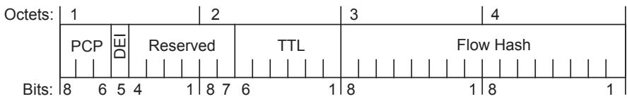
Figure 44-1—Flow FilteringTCI format
The F-TAG TCI contains the following fields:
a) PCP (Priority Code Point)—This 3-bit field encodes the priority and drop_eligible parameters of the service request primitive associated with this frame using the same encoding as specified for VLAN tags in 6.9.3.
b) DEI (Drop Eligible Indicator)—This 1-bit field carries the drop_eligible parameter of the service request primitive associated with this frame.
c) Reserved—This 6-bit field may be used for future format variations. The Reserved field contains a value of zero when the tag is encoded and is ignored when the tag is decoded.
d) TTL (Time To Live)—This 6-bit field holds a counter value that is decremented each time the F-TAG is read (44.2.2.1) and provides a mechanism to limit the number of network hops a frame may take.
e) Flow Hash—This 16-bit field carries a flow hash value used in the dynamic port selection process for ECMP (8.8.3).
44.2.2 F-TAG processing
This standard specifies flow filtering behavior for SPBM ECMP (44.2). To support this behavior, a flow hash may be conveyed in a mac_service_data_unit using an F-TAG (44.2.1). This clause specifies a Support for Flow Filtering shim that produces and processes F-TAG information. The shim has two EISS SAPs—a lower EISS toward a LAN and an upper EISS toward the MAC Relay Entity.
At the boundary of a flow filtering SPT Domain, for example, at CBPs, the flow hash is generated for EM_UNITDATA.indication primitives. At intermediate ports, for example, PNPs, the F-TAG is generated using the flow hash in EM_UNITDATA.request primitives or processed to retrieve the flow hash value from EM_UNITDATA.indication primitives. The F-TAG also includes a TTL field, used for loop mitigation, and PCP and DEI fields that are processed by this shim.
Flow filtering support is governed by a Flow Filtering Control Table for each port containing an entry for each VID with the following fields:
a) Flow Filtering (enabled/disabled). This field indicates whether flow filtering behavior is enabled on the port for the VID. The default value is disabled.
b) Flow Hash Generation (enabled/disabled). This field indicates whether flow hash generation is enabled on the port for the VID. The default value is disabled.
c) TTL Value (1..63). This field is the initial TTL value for frames entering the flow filtering SPT Domain [item d) in 12.16.5.5.2]. The default value is 8.
The Flow Filtering Control Table is provisioned by ISIS-SPB (44.1.2). For flow filtering, a CBP will have both the Flow Filtering field and the Flow Hash Generation field set to enabled and the TTL Value field set to provide the initial time_to_live value for indication primitives. For flow filtering, a PNP will have the Flow Filtering field set to enabled and the Flow Hash Generation field set to disabled. The TTL Value field (initial TTL value) is not used on a PNP.
NOTE—Based on the description above, for flow filtering, the condition “Flow Hash Generation field indicates enabled” is equivalent to indicating a CBP, and the condition “Flow Hash Generation field indicates disabled” is equivalent to indicating a PNP.
44.2.2.1 Data indications
On receipt of an EM_UNITDATA.indication primitive from the lower EISS on a PNP, the received frame shall be discarded if
a) For the vlan_identifier in the Flow Filtering Control Table, the Flow Filtering field indicates enabled, and the initial octets of the mac_service_data_unit do not contain a valid F-TAG; or
b) The value in the TTL field in the F-TAG is 0.
NOTE 1—A frame received with a TTL value of 0 will be discarded, i.e., not relayed, even if it is addressed to another port on the receiving Bridge.
Otherwise, an EM_UNITDATA.indication primitive is invoked at the upper EISS with parameter values determined from the received primitive based on the Flow Filtering Control Table for the received vlan_identifier as follows:
c) If the Flow Filtering field indicates disabled, the invoked primitive is identical to the received primitive.
d) If the Flow Filtering field indicates enabled, the destination_address, source_address, vlan_identifier, and connection_identifier in the invoked primitive are identical to those parameters in the received primitive.
e) If the Flow Filtering field indicates enabled and the Flow Hash Generation field indicates disabled, the mac_service_data_unit in the invoked primitive is created by removing the F-TAG from the received mac_service_data_unit; otherwise, the mac_service_data_unit in the invoked primitive is identical to the received primitive.
The value of the flow_hash and time_to_live parameters are determined as follows:
f) If the Flow Hash Generation field indicates enabled, the value of flow_hash is generated from the received primitive (using a process selected by the implementation). time_to_live is set to the TTL Value from the Flow Filtering Control Table for the received vlan_identifier.
NOTE 2—Procedures for calculating the flow hash are not covered by this standard. The procedure is typically a protocol-dependent hash of the client protocol header being carried within the mac_service_data_unit.
NOTE 3—There is often a compromise between the speed of a hash calculation and the quality of value spreading. This standard makes no assurances regarding the quality of the distribution of flow_hash values.
g) If the Flow Hash Generation field indicates disabled, the value of flow_hash is taken from the Flow Hash field in the received F-TAG, and time_to_live is set to the TTL value in the received F-TAG decremented by 1.
The value of the drop_eligible and priority parameters are determined as follows:
h) If the mac_service_data_unit was tagged with an F-TAG, the value of the drop_eligible parameter and the received priority value are decoded as described in 6.9.3, using the PCP and DEI values from the F-TAG. Otherwise,
i) The received priority value and the drop_eligible parameter value are the values in the EM_UNITDATA.indication.
j) The value of the priority parameter is then regenerated from the received priority, as specified in 6.9.4.
44.2.2.2 Data requests
On invocation of an EM_UNITDATA.request primitive at the upper EISS, an EM_UNITDATA.request primitive is invoked at the lower EISS, with parameter values determined based on the Flow Filtering Control Table for the received vlan_identifier.
If the Flow Filtering field indicates disabled or the Flow Hash Generation field indicates enabled, the invoked primitive is identical to the received primitive.
If the Flow Filtering field indicates enabled and the Flow Hash Generation field indicates disabled, all parameters in the invoked primitive match those in the received primitive except the mac_service_data_unit. The mac_service_data_unit in the invoked primitive is formed by inserting an F-TAG as the initial octets to the received mac_service_data_unit. The values of the flow_hash, time_to_live, priority, and drop_eligible parameters are used to determine the contents of the F-TAG, in accordance with 44.2.1.
44.2.3 Forwarding process extension for flow filtering
Frame filtering (8.6.3) reduces the set of potential transmission ports in accordance with applicable FDB entries. When flow filtering is enabled, the ISIS-SPB control plane creates Dynamic Filtering Entries with multiple forwarding Ports in the Port Map when there are multiple equal cost hops to a given individual address. Frame filtering must select only one of these forwarding ports on which to transmit each frame with a matching destination_address and VID.
Selection of one Port from a set indicated by the Port Map shall be performed using a form of the FNV noncryptographic hash algorithm as follows:
For a Port Map specifying k potential forwarding Ports, let P be an ordered list of potential forwarding Ports sorted from greatest to least neighbor SPB System Identifier and $\mathrm { P } _ { i }$ be the ith Port in P. Thus $\mathrm { P _ { 0 } }$ is the Port whose neighbor has the greatest SPB System Identifier, and $\mathrm { P } _ { k - 1 }$ is the Port whose neighbor has the least SPB System Identifier. The following dynamic port selection process is used to select a value for i, thus selecting Port $\mathrm { P } _ { i }$ to be the transmission port:
a) Set a 32-bit variable hash32 to 0x811C9DC5;
b) For each octet $\mathrm { O } _ { j }$ (extended to 32 bits with leading 0’s) in the Bridge’s SPB System Identifier (8.13.8), starting with the least significant octet (octet 5) and progressing to the most significant octet (octet 0), set hash32 to ((hash32 XOR $\mathrm { O } _ { i } ) \times 0 \mathrm { x } 0 1 0 0 0 1 9 3 )$ ;
c) For each octet $\mathrm { O } _ { j }$ (extended to 32 bits with leading 0’s) in the flow_hash parameter, starting with the least significant octet (octet 4 of Figure 44-1) and progressing to the most significant octet (octet 3 of Figure 44-1), set hash32 to ((hash32 XOR Oj) 0x01000193);
d) Set a 16-bit variable hash16 to ((hash32 and 0x0000FFFF) XOR (hash32 / 0x00010000));
e) Set i to (hash16 mod k), selecting Port $\mathrm { P } _ { i } .$
44.2.4 TTL Loop mitigation
The F-TAG contains a TTL field whose value is decremented each time a frame is forwarded by an SPT Bridge supporting flow filtering [item g) in 44.2.2]. A frame is filtered (discarded) if it is received with a TTL value of 0. This mechanism mitigates the impact of looping frames by limiting the number of hops these frames may travel in the network. This method of loop mitigation protects network resources by ensuring frames are forwarded at most a fixed number of times.
NOTE—The TTL carried in the F-TAG is decremented for all frames; however, the Flow Hash is applicable only to unicast frames. The Flow Hash has no effect on the filtering of group addressed frames.
44.2.5 CFM for ECMP with flow filtering
CFM as specified in Clause 18 through Clause 22 provides capabilities useful in detecting, isolating, and reporting connectivity faults. SPBM MAs (27.18) can be used with an ECMP VID and provide most of the necessary CFM functionality. One additional MA type is specified for ECMP, the ECMP path MA, because an SPBM path MA can test only one path between a pair of endpoints.
An ECMP path MA is used to continuously test multiple paths between two endpoints. This type of MA has only two MEPs at two SPT Region boundary ports. The MA is identified by a TE-SID comprising an ESP in each direction between the two endpoints. An ECMP path MEP cycles through a set of flow hash values intended to direct the CCM frames along (and thus test) different paths to the other MEP in the MA. Each flow hash is used in multiple consecutive CCM frames so that a fault on a particular path will be detected and reported back via an RDI signal. This standard does not specify the mechanisms that would be necessary to support Loopback and Linktrace on an ECMP path MA since full Loopback and Linktrace coverage can be provided by an SPBM VID MA. Therefore, there are no MHFs associated with an ECMP path MA.
44.2.5.1 ECMP path MEP placement in a Bridge Port
Since ECMP path MEPs must only see traffic from one other endpoint, these MEPs need to be further differentiated by the TESI Multiplex Entity (6.19). This locates an ECMP path MEP so that it receives CCMs only from the other MEP in its MA. Figure 44-2 shows an example of ECMP path MEPs on a CBP.
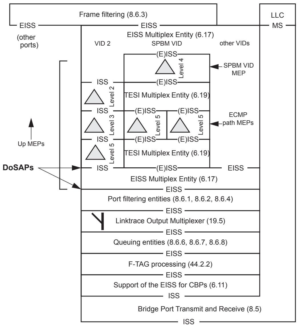
Figure 44-2—SPBM VID MEP and ECMP path MEP placement in a CBP
44.2.5.2 Continuity Check protocol in an ECMP path MA
The Continuity Check protocol is described in 20.1 and the corresponding state machines in Clause 20. The modifications required to realize ECMP path MAs include the following:
a) The MEP Continuity Check Initiator state machine adds three variables for controlling ECMP path testing (20.10.4, 20.10.5, 20.10.6) and shares two of these with the Remote MEP state machine (Figure 20-1);
b) The destination_address parameter is set to the individual MAC address of the other MEP in the MA [item a) in 20.11.1];
c) The flow_hash parameter is set to one of the values to be tested, and the time_to_live parameter is set as specified in item e) in 20.11.1;
d) The MEP Continuity Check initiator state machine is modified to support a cycle of path tests for an ECMP path MEP (20.12);
e) The Remote MEP state machine is modified to track a cycle of path test RDI values and report rMEPlastRDI as set if any RDI has been seen in the last path test cycle for an ECMP path MEP (20.19.2, 20.20).
NOTE—In an ECMP path MEP testing a set of paths, the RDI signal reflects back the state of far end CCM reception. Using the current CCM sending cycle position (pathN), the CCM sending rate, and the path round trip delay, one can calculate roughly the position in the sending cycle corresponding to a received RDI. This approach makes minimal changes to the CCM state machines at the CCM sending MEP and no changes at the CCM receiving MEP. It is subject to some ambiguity based on differences in path delay, the sending rate, and cycle length. In the case of ambiguous results, further testing would be required to identify a faulty path.
SPBM MAs may also implement the following enhancements to the Continuity Check protocol:
f) The procedure MEPprocessEqualCCM() on ECMP path MEPs does not include the check of the MAID on received CCMs [item b) in 20.17.1].
All other Continuity Check processes are the same as those for a VID-based MA.
44.2.6 Operation with selective support for flow filtering
When adding new capabilities to a network, it is desirable to make changes incrementally rather than perform a wholesale upgrade (e.g., incur a “flag day” event). Flow filtering is optional functionality that can be used with selected Base-VIDs while not adversely affecting other services in the network. However, flow filtering changes frame encoding (i.e., adds new header information in an F-TAG) and therefore requires that a Base-VID using ECMP with flow filtering have all its boundary points capable of processing the F-TAG. To enable incremental incorporation of flow filtering, ISIS-SPB requires F-TAG support for any Bridges with a CBP associated with a Base VID using ECMP with flow filtering while allowing other Bridges in the SPT region to operate without flow filtering support.
When the ECMP ECT-ALGORITHM value indicates support for flow filtering (Table 28-1), an I-SID cannot be configured to use a Base VID using ECMP with flow filtering unless the Bridge supports flow filtering (12.16.5.2). Requiring all Bridges advertising service instances using ECMP with flow filtering to support F-TAG processing provides for proper handling of F-tagged frames at the boundary of the SPT Domain.
Within the SPT Domain, it is possible to use Bridges that support the ECMP ECT Algorithm but do not support flow filtering (i.e., do not recognize F-TAGs). In this case, the ECMP ECT Algorithm (28.9) selects one port from the set of equal cost forwarding ports for each individual address and creates a Dynamic Filtering Entry for the address indicating the selected port.
NOTE—Bridges that do not support flow filtering should not change PCP and DEI values for frames carrying F-TAGs as this may not provide the desired behavior. If the PCP and DEI values are changed in the VLAN tag only, the PCP and DEI values carried in the F-TAG will be reasserted when the F-TAG is next processed.
These ECMP behaviors enable incremental upgrade of edge bridges to support flow filtering and selective use of this capability with I-SIDs registered only at these upgraded edge bridges. ECMP operation with selective support for flow filtering enables incremental introduction of flow filtering capabilities into an existing network and earlier introduction of flow filtering support for selected services.
Annex A
(normative)
PICS proforma—Bridge implementations42
A.1 Introduction
The supplier of a protocol implementation that is claimed to conform to this standard shall complete the following Protocol Implementation Conformance Statement (PICS) proforma.
A completed PICS proforma is the PICS for the implementation in question. The PICS is a statement of which capabilities and options of the protocol have been implemented. The PICS can have a number of uses, including use
a) By the protocol implementer, as a checklist to reduce the risk of failure to conform to the standard through oversight;
b) By the supplier and acquirer—or potential acquirer—of the implementation, as a detailed indication of the capabilities of the implementation, stated relative to the common basis for understanding provided by the standard PICS proforma;
c) By the user—or potential user—of the implementation, as a basis for initially checking the possibility of interworking with another implementation (note that, while interworking can never be guaranteed, failure to interwork can often be predicted from incompatible PICSs);
By a protocol tester, as the basis for selecting appropriate tests against which to assess the claim for conformance of the implementation.
A.2 Abbreviations and special symbols
A.2.1 Status symbols
<table><tr><td>M</td><td>mandatory</td></tr><tr><td>O</td><td>optional</td></tr><tr><td>O.n</td><td>optional, but support of at least one of the group of options labeled by the same numeral n is required</td></tr><tr><td>X</td><td>prohibited</td></tr><tr><td>pred:</td><td>conditional-item symbol, including predicate identification: see A.3.4</td></tr><tr><td><eq>\neg</eq></td><td>logical negation, applied to a conditional item’s predicate</td></tr></table>
A.2.2 General abbreviations
<table><tr><td>N/A</td><td>not applicable</td></tr><tr><td>PICS</td><td>Protocol Implementation Conformance Statement</td></tr></table>
A.3 Instructions for completing the PICS proforma
A.3.1 General structure of the PICS proforma
The first part of the PICS proforma, implementation identification and protocol summary, is to be completed as indicated with the information necessary to identify fully both the supplier and the implementation.
The main part of the PICS proforma is a fixed-format questionnaire, divided into several subclauses, each containing a number of individual items. Answers to the questionnaire items are to be provided in the rightmost column, either by simply marking an answer to indicate a restricted choice (usually Yes or No) or by entering a value or a set or range of values. (Note that there are some items where two or more choices from a set of possible answers can apply; all relevant choices are to be marked.)
Each item is identified by an item reference in the first column. The second column contains the question to be answered; the third column records the status of the item—whether support is mandatory, optional, or conditional: see also A.3.4. The fourth column contains the reference or references to the material that specifies the item in the main body of this standard, and the fifth column provides the space for the answers.
A supplier may also provide (or be required to provide) further information, categorized as either Additional Information or Exception Information. When present, each kind of further information is to be provided in a further subclause of items labeled Ai or Xi, respectively, for cross-referencing purposes, where i is any unambiguous identification for the item (e.g., simply a numeral). There are no other restrictions on its format and presentation.
A completed PICS proforma, including any Additional Information and Exception Information, is the Protocol Implementation Conformation Statement for the implementation in question.
NOTE—Where an implementation is capable of being configured in more than one way, a single PICS may be able to describe all such configurations. However, the supplier has the choice of providing more than one PICS, each covering some subset of the implementation’s configuration capabilities, in case that makes for easier and clearer presentation of the information.
A.3.2 Additional information
Items of Additional Information allow a supplier to provide further information intended to assist the interpretation of the PICS. It is not intended or expected that a large quantity will be supplied, and a PICS can be considered complete without any such information. Examples might be an outline of the ways in which a (single) implementation can be set up to operate in a variety of environments and configurations, or information about aspects of the implementation that are outside the scope of this standard but that have a bearing on the answers to some items.
References to items of Additional Information may be entered next to any answer in the questionnaire and may be included in items of Exception Information.
A.3.3 Exception information
It may occasionally happen that a supplier will wish to answer an item with mandatory status (after any conditions have been applied) in a way that conflicts with the indicated requirement. No preprinted answer will be found in the Support column for this item. Instead, the supplier shall write the missing answer into the Support column, together with an Xi reference to an item of Exception Information, and shall provide the appropriate rationale in the Exception item itself.
An implementation for which an Exception item is required in this way does not conform to this standard.
NOTE—A possible reason for the situation described previously is that a defect in this standard has been reported, a correction for which is expected to change the requirement not met by the implementation.
A.3.4 Conditional status
A.3.4.1 Conditional items
The PICS proforma contains a number of conditional items. These are items for which both the applicability of the item itself, and its status if it does apply—mandatory or optional—are dependent on whether certain other items are supported.
Where a group of items is subject to the same condition for applicability, a separate preliminary question about the condition appears at the head of the group, with an instruction to skip to a later point in the questionnaire if the “Not Applicable” answer is selected. Otherwise, individual conditional items are indicated by a conditional symbol in the Status column.
A conditional symbol is of the form “pred: S” where pred is a predicate as described in A.3.4.2 below, and S is a status symbol, M or O.
If the value of the predicate is true (see A.3.4.2), the conditional item is applicable, and its status is indicated by the status symbol following the predicate: The answer column is to be marked in the usual way. If the value of the predicate is false, the “Not Applicable” (N/A) answer is to be marked.
A.3.4.2 Predicates
A predicate is one of the following:
a) An item-reference for an item in the PICS proforma: The value of the predicate is true if the item is marked as supported and is false otherwise;
b) A predicate-name, for a predicate defined as a boolean expression constructed by combining itemreferences using the boolean operator OR: The value of the predicate is true if one or more of the items is marked as supported;
c) The logical negation symbol “¬” prefixed to an item-reference or predicate-name: The value of the predicate is true if the value of the predicate formed by omitting the “¬” symbol is false, and vice versa.
Each item whose reference is used in a predicate or predicate definition, or in a preliminary question for grouped conditional items, is indicated by an asterisk in the Item column.
A.4 PICS proforma for IEEE Std 802.1Q—Bridge implementations
A.4.1 Implementation identification
<table><tr><td>Supplier</td><td></td></tr><tr><td>Contact point for queries about the PICS</td><td></td></tr><tr><td>Implementation Name(s) and Version(s)</td><td></td></tr><tr><td>Other information necessary for full identification, e.g., name(s) and version(s) of machines and/or operating system names</td><td></td></tr><tr><td colspan="2">NOTE 1—Only the first three items are required for all implementations; other information may be completed as appropriate in meeting the requirement for full identification.NOTE 2—The terms “Name” and “Version” should be interpreted appropriately to correspond with a supplier’s terminology (e.g., Type, Series, Model).</td></tr></table>
A.4.2 Protocol summary, IEEE Std 802.1Q
<table><tr><td>Identification of protocol specification</td><td colspan="3">IEEE Std 802.1Q-2014, IEEE Standards for Local and metropolitan area networks—Bridges and Bridged Networks</td></tr><tr><td rowspan="2">Identification of amendments and corrigenda to the PICS proforma that have been completed as part of the PICS</td><td colspan="3">Amd. : Corr. :</td></tr><tr><td colspan="3">Amd. : Corr. :</td></tr><tr><td>Have any Exception items been required?(See A.3.3: the answer “Yes” means that the implementation does not conform to IEEE Std 802.1Q)</td><td colspan="3">No [ ] Yes [ ]</td></tr></table>
<table><tr><td>Date of Statement</td><td></td></tr></table>
A.5 Major capabilities
<table><tr><td>Item</td><td>Feature</td><td>Status</td><td>References</td><td>Support</td></tr><tr><td></td><td>If the implementation is an end station implementation, mark “N/A” and continue at Annex B.</td><td></td><td></td><td>N/A [ ]</td></tr><tr><td>MAC</td><td>Do the implementations of MAC technologies and support of the MAC Internal Sublayer Service (ISS) conform to MAC standards as specified in IEEE Std 802.1AC?(If support of a specific MAC technology is claimed, any PICS proforma(s) required by the standard specifying that technology shall also be completed.)</td><td>M</td><td>A.6, IEEE Std 802.1AC</td><td>Yes [ ]</td></tr><tr><td>LLC</td><td>Is a class of LLC supporting Type 1 operations supported on all Bridge Ports in conformance with ISO/IEC 8802-2? (The PICS proforma required by ISO/IEC 8802-2 shall also be completed.)</td><td>M</td><td>8.2, 8.3, 8.13, ISO/IEC 8802-2</td><td>Yes [ ]</td></tr><tr><td>RLY</td><td>Does the implementation relay and filter frames as specified?</td><td>M</td><td>8.5, 8.6, 8.7, 6.12, 8.8, A.7</td><td>Yes [ ]</td></tr><tr><td>BFS</td><td>Does the implementation maintain the information required to make frame filtering decisions and support Basic Filtering Services?</td><td>M</td><td>8.1, 8.5, 8.7, 8.8, A.8</td><td>Yes [ ]</td></tr><tr><td>ADDR</td><td>Does the implementation conform to the provisions for addressing?</td><td>M</td><td>8.13, A.9</td><td>Yes [ ]</td></tr><tr><td>TPMR</td><td>Can the Bridge be configured to operate as a Two Port MAC Relay?</td><td>O.2</td><td>5.16</td><td>Yes [ ] No [ ]</td></tr><tr><td>MSP</td><td>Is the operation of the MAC Status Propagation Entity (MSPE) supported?</td><td>TPMR: M</td><td>23</td><td>Yes [ ] N/A [ ]</td></tr><tr><td>RSTP</td><td>Is RSTP implemented?</td><td>-TPMR:O.1 TPMR:X</td><td>5, 13, 14, A.10</td><td>Yes [ ] No [ ]</td></tr><tr><td>BPDU</td><td>Are transmitted Bridge Protocol Data Units (BPDUs) encoded and received BPDUs validated as specified?</td><td>-TPMR:M TPMR:X</td><td>A.11, 13.29.27, 13.29.28, 13.29.29, 14</td><td>Yes [ ] No [ ]</td></tr><tr><td>IMP</td><td>Are the required implementation parameters included in this completed PICS?</td><td>M</td><td>8.8, A.12</td><td>Yes [ ]</td></tr><tr><td>PERF</td><td>Are the required performance parameters included in this completed PICS?(Operation of the Bridge within the specified parameters shall not violate any of the other conformance provisions of this standard.)</td><td>M</td><td>8.5, A.13</td><td>Yes [ ]</td></tr><tr><td>MGT</td><td>Is management of the Bridge supported?</td><td>O PBBTE OR TPMR: M</td><td>5, A.14</td><td>Yes [ ] No [ ]</td></tr><tr><td>RMGT</td><td>Is a remote management protocol supported?</td><td>MGT:O PBBTE OR TPMR: M</td><td>5, A.15</td><td>Yes [ ] No [ ]</td></tr></table>
A.5 Major capabilities (continued)
<table><tr><td>Item</td><td>Feature</td><td>Status</td><td>References</td><td colspan="2">Support</td></tr><tr><td>MIB</td><td>Does the system implementation support management operations using SMIv2 MIB modules?</td><td>MGT:O</td><td>8.12, 17</td><td>Yes [ ]</td><td>No [ ]</td></tr><tr><td>TC</td><td>Are multiple traffic classes supported for relaying frames?</td><td>O</td><td>8.6.6, 8.6.7, 8.6.8, A.16</td><td>Yes [ ]</td><td>No [ ]</td></tr><tr><td>EFS</td><td>Are Extended Filtering Services supported for relaying and filtering frames?</td><td>-TPMR:OTPMR:X</td><td>A.17, 6.12</td><td>Yes [ ]</td><td>No [ ]</td></tr><tr><td>MMRP</td><td>Is the operation of the Multiple MAC Registration Protocol supported?</td><td>EFS:M</td><td>5.4.1, A.20</td><td>Yes [ ]</td><td>No [ ]</td></tr><tr><td>VLAN</td><td>Does the implementation support the ability to insert tag headers into, modify tag headers in, and remove tag headers from relayed frames?</td><td>-TPMR:MTPMR:X</td><td>5.4, 6.3, 6.8, 6.9, 8.6, 6.12, 9</td><td>Yes [ ]</td><td></td></tr><tr><td>VTR</td><td>Does the implementation support a VLAN Identifier (VID) translation table?</td><td>-TPMR:OTPMR:X</td><td>6.9</td><td>Yes [ ]</td><td>No [ ]</td></tr><tr><td>MVRP</td><td>Is automatic configuration and management of VLAN topology using MVRP supported?</td><td>-TPMR:MTPMR:X</td><td>5.4, A.21</td><td>Yes [ ]</td><td></td></tr><tr><td>MRP</td><td>Is the Multiple Registration Protocol (MRP) implemented in support of MRP Applications?</td><td>MMRP:MMVRP:M</td><td>10A.20, A.21, A.22</td><td>Yes [ ]</td><td></td></tr><tr><td>MRP1</td><td>Does the MRP implementation support operation of the Full Participant?</td><td>MRP:O.4</td><td>10A.22</td><td>Yes [ ]</td><td>No [ ]</td></tr><tr><td>MRP2</td><td>Does the MRP implementation support operation of the Full Participant, point-to-point subset?</td><td>MRP:O.4</td><td>10A.22</td><td>Yes [ ]</td><td>No [ ]</td></tr><tr><td>MSTP</td><td>Is MSTP implemented?</td><td>-TPMR:O.1TPMR:X</td><td>5, 7, 8.4, 8.6.1, 8.8.8, 8.9, 8.10, 8.13.7, 11.2.3.1.2, 13, 14, A.18</td><td>Yes [ ]</td><td>No [ ]</td></tr><tr><td>VMGT</td><td>Does the implementation support VLAN management operations?</td><td>-TPMR AND MGT:OTPMR:X</td><td>5.4.1, 12.10.2, 12.10.3</td><td>Yes [ ]</td><td>No [ ]</td></tr><tr><td>CB</td><td>Can the Bridge be configured to operate as a C-VLAN Bridge, recognizing and using C-TAGs?</td><td>O.2</td><td>5.9</td><td>Yes [ ]</td><td>No [ ]</td></tr><tr><td>PB</td><td>Can the Bridge be configured to operate as a Provider Bridge, recognizing and using S-TAGs?</td><td>O.2</td><td>5.10</td><td>Yes [ ]</td><td>No [ ]</td></tr><tr><td>PEB</td><td>Can the Bridge be configured to operate as a Provider Edge Bridge with one or more Ports operating as Customer Edge Ports (CEPs)?</td><td>PB:O</td><td>5.10.2</td><td>Yes [ ]</td><td>No [ ]</td></tr><tr><td>RCSI</td><td>Can the Bridge be configured to operate as a Provider Edge Bridge with one or more Ports operating as Remote Customer Access Ports (RCAPs)?</td><td>PEB:O</td><td>5.10.2</td><td>Yes [ ]</td><td>No [ ]</td></tr></table>
A.5 Major capabilities (continued)
<table><tr><td>Item</td><td>Feature</td><td>Status</td><td>References</td><td>Support</td></tr><tr><td>PB-2</td><td>State which Ports support the following values for the Provider Bridge Port Type:— PNP— CNP— CEP— RCAP</td><td>PB:M</td><td>5.10</td><td>Ports: ____Ports: ____Ports: ____</td></tr><tr><td>CFM</td><td>Is Connectivity Fault Management (CFM) implemented?</td><td>O PBBTE: M</td><td>5.4.1.4, 19, 20, 21, 22</td><td>Yes [ ] No [ ]</td></tr><tr><td>CFM-T</td><td>Does the implementation support a CFM MD-level zero MIP on each Port?</td><td>TPMR:M</td><td>5.15, 18–22</td><td>Yes [ ]</td></tr><tr><td>BRG</td><td>Is this system a Bridge, and not a Station, for the purposes of CFM?</td><td>CFM: O</td><td>22.4</td><td>Yes [ ] No [ ]</td></tr><tr><td>BEB</td><td>Can the Bridge be configured to operate as a Backbone Edge Bridge, recognizing and using I-TAGs?</td><td>O.2</td><td>5.12</td><td>Yes [ ] No [ ]</td></tr><tr><td>BEB-B</td><td>Can the Bridge be configured to operate as a Backbone Edge Bridge with one or more Ports operating as a Customer Backbone Ports (CBPs)?</td><td>BEB: O.3</td><td>5.12</td><td>Yes [ ] No [ ]</td></tr><tr><td>BEB-I</td><td>Can the Bridge be configured to operate as a Backbone Edge Bridge with one or more Ports operating as a Provider Instance Port (PIP)?</td><td>BEB: O.3</td><td>5.12</td><td>Yes [ ] No [ ]</td></tr><tr><td>BEB-1</td><td>State which Ports support the following values for the Backbone Edge Bridge Port Type:— PIP— CNP— PNP— CBP— CEP— RCAP</td><td>BEB: M</td><td>5.11</td><td>PIP: ____CNP: ____PNP: ____CBP: ____CEP: ____RCAP: ____</td></tr><tr><td>DDCFM</td><td>Is management of data-driven and data-dependent connectivity faults implemented?</td><td>O</td><td>19, 29</td><td>Yes[ ] No [ ]</td></tr><tr><td>PBBTE</td><td>Can the Bridge be configured by an external agent to provide TESIs?</td><td>O</td><td>8.4, 8.9, 25.10</td><td>Yes [ ] No [ ]</td></tr><tr><td>EXAG</td><td>Is the active topology, learning and forwarding of the TESIs under the control of an external agent?</td><td>PBBTE: O.1</td><td>8.4, 8.9</td><td>Yes [ ] No [ ]N/A [ ]</td></tr><tr><td>ESPVID</td><td>Are the VIDs associated with ESPs, the ESP-VIDs, allocated to the TE-MSTID?</td><td>PBBTE: M</td><td>8.9</td><td>Yes [ ] N/A [ ]</td></tr><tr><td>ESPFID</td><td>Is every ESP-VID allocated to a distinct FID?</td><td>PBBTE: M</td><td>25.10</td><td>Yes [ ] N/A [ ]</td></tr><tr><td>BCBTE</td><td>Can the Bridge be configured to operate as a Backbone Core Bridge (BCB) that provides TESIs?</td><td>PB AND PBBTE: O.5</td><td>5.10, 5.6.2</td><td>Yes [ ] N/A [ ]</td></tr><tr><td>BEBTE</td><td>Can the Bridge be configured to operate as a Backbone Edge Bridge that provides TESIs?</td><td>BEB AND PBBTE: O.5</td><td>5.8.2, 5.12.1</td><td>Yes [ ] N/A [ ]</td></tr><tr><td>PS</td><td>Is protection switching supported?</td><td>BEBTE: M</td><td>5.8.2, 26.10.3</td><td>Yes [ ] N/A [ ]</td></tr></table>
A.5 Major capabilities (continued)
<table><tr><td>Item</td><td>Feature</td><td>Status</td><td>References</td><td colspan="2">Support</td></tr><tr><td>FQTSS</td><td>Does the implementation support Forwarding and Queuing Enhancements for time-sensitive streams?</td><td>O</td><td>5.4.1.5, 34</td><td>Yes [ ]</td><td>No [ ]</td></tr><tr><td>CN</td><td>Is congestion notification implemented?</td><td>O</td><td>5.4.3, 30, 31, 32, 33</td><td>Yes [ ]</td><td>No [ ]</td></tr><tr><td>BRG1</td><td>Is this system a Bridge, and not an end station, for the purposes of congestion notification?</td><td>CN: O</td><td></td><td>Yes [ ]</td><td>No [ ]</td></tr><tr><td>SRP</td><td>Does the implementation support the Stream Reservation Protocol?</td><td>O</td><td>35</td><td>Yes [ ]</td><td>No [ ]</td></tr><tr><td>MIRP</td><td>Is the Multiple I-SID Registration Protocol supported?</td><td>BEB-I OR BEB-B: O</td><td>5.7.1:e, 5.8.1:e</td><td>Yes [ ]</td><td>No [ ]</td></tr><tr><td>PFC</td><td>Is Priority-based Flow Control implemented?</td><td>O</td><td>5.11, 36</td><td>Yes [ ]</td><td>No [ ]</td></tr><tr><td>ETS</td><td>Does the implementation support bandwidth management using ETS?</td><td>O</td><td>37</td><td>Yes [ ]</td><td>No [ ]</td></tr><tr><td>DCBX</td><td>Does the implementation support configuration management via DCBX?</td><td>O</td><td>38</td><td>Yes [ ]</td><td>No [ ]</td></tr><tr><td>IPS</td><td>Is Infrastructure Protection Switching supported?</td><td>PBBTE: O</td><td>5.6.2, 5.8.2, 26.11</td><td>Yes [ ] N/A [ ]</td><td>No [ ]</td></tr><tr><td>SPB</td><td>Is Shortest Path Bridging supported?</td><td>O.1</td><td>5.4.5, 27</td><td>Yes [ ]</td><td>No [ ]</td></tr><tr><td>EVB-B</td><td>Does the implementation support the functionality of an EVB Bridge?</td><td>O</td><td>5.23</td><td>Yes [ ]</td><td>No [ ]</td></tr><tr><td>EVB-S</td><td>Does the implementation support the functionality of an EVB station?</td><td>O</td><td>5.24</td><td>Yes [ ]</td><td>No [ ]</td></tr><tr><td>ECMP</td><td>Is Equal Cost Multiple Paths supported?</td><td>SPBM:O</td><td>5.4.5.1, 44.1</td><td>Yes [ ]</td><td>No [ ]</td></tr><tr><td>FF</td><td>Is flow filtering supported, including inserting, modifying, and removing F-TAGs from relayed frames?</td><td>ECMP:O</td><td>5.4.5.2, 44.2</td><td>Yes [ ]</td><td>No [ ]</td></tr><tr><td>FF-S</td><td>Does the S-VLAN component support F-TAG processing on each PNP?</td><td>PB AND FF:M</td><td>5.6.4, 44.2.2</td><td>Yes [ ]</td><td>No [ ]</td></tr><tr><td>FF-B</td><td>Does the B-component support F-TAG processing on each CBP and PNP?</td><td>BEB AND FF:M</td><td>5.8.4, 44.2.2</td><td>Yes [ ]</td><td>No [ ]</td></tr></table>
A.6 Media access control methods
<table><tr><td>Item</td><td>Feature</td><td>Status</td><td>References</td><td>Support</td></tr><tr><td></td><td>Which media access control methods are implemented in conformance with the relevant MAC Standards?</td><td></td><td>5.4, IEEE Std 802.1AC</td><td></td></tr><tr><td>MAC-802.3</td><td>Ethernet, IEEE Std 802.3</td><td>O.2</td><td>IEEE Std</td><td>Yes [ ] No [ ]</td></tr><tr><td>MAC-802.11</td><td>Wireless LAN, IEEE Std 802.11</td><td>O.2</td><td>802.1AC</td><td>Yes [ ] No [ ]</td></tr><tr><td>MAC-802.17</td><td>Resilient packet ring (RPR)</td><td>O.2</td><td></td><td>Yes [ ] No [ ]</td></tr><tr><td>MAC-802.20-WB</td><td>IEEE 802.20 Wideband Mode</td><td>O.2</td><td></td><td>Yes [ ] No [ ]</td></tr><tr><td>MAC-802.20-625</td><td>IEEE 802.20 625k-MC Mode</td><td>O.2</td><td></td><td>Yes [ ] No [ ]</td></tr><tr><td>MAC-1</td><td>Has a PICS been completed for each of the media access control methods implemented as required by the relevant MAC standards?</td><td>M</td><td></td><td>Yes[ ]</td></tr><tr><td>MAC-2</td><td>Do all the media access control methods implemented support the MAC ISS as specified?</td><td>M</td><td>IEEE Std 802.1AC</td><td>Yes [ ]</td></tr><tr><td>MAC-3</td><td>Are the adminPointToPointMAC and operPointToPointMAC parameters implemented on all Ports?</td><td>M</td><td>IEEE Std 802.1AC</td><td>Yes [ ]</td></tr><tr><td>MAC-4</td><td>Does the implementation support the use of the adminEdgePort and operEdgePort parameters on any Ports?</td><td>O</td><td>13.27.1, 13.27.44</td><td>Yes [ ] No [ ]</td></tr><tr><td>MAC-4a</td><td>State which Bridge Ports support the adminEdgePort and operEdgePort parameters.</td><td></td><td></td><td>Ports____</td></tr><tr><td>MAC-5</td><td>Is the priority of received frames set to the Default Priority where specified for the MAC?</td><td>M</td><td>IEEE Std 802.1AC</td><td>Yes[ ]</td></tr><tr><td>MAC-6</td><td>Can the Default Priority be set for each Port?</td><td>O</td><td>IEEE Std 802.1AC</td><td>Yes [ ] No [ ]</td></tr><tr><td>MAC-7</td><td>Can the Default Priority be set to any of 0–7?</td><td>MAC-6:M</td><td>IEEE Std 802.1AC</td><td>Yes[ ]</td></tr><tr><td>MAC-12</td><td>Is the minimum tagged frame length that can be transmitted on IEEE 802.3 Ports less than 68 (but 64 or more) octets?</td><td>MAC-802.3:O</td><td>IEEE Std 802.1AC</td><td>Yes [ ] No [ ] N/A [ ]</td></tr></table>
A.7 Relay and filtering of frames
<table><tr><td>Item</td><td>Feature</td><td>Status</td><td>References</td><td>Support</td></tr><tr><td>RLY-1</td><td>Are received frames with MAC method errors discarded?</td><td>M</td><td>6.3, 8.5</td><td>Yes [ ]</td></tr><tr><td>RLY-2</td><td>Are user data frames the only type of frame relayed?</td><td>M</td><td>8.5</td><td>Yes [ ]</td></tr><tr><td>RLY-3</td><td>Is the priority of each frame relayed regenerated as specified?</td><td>-TPMR: MTPMR: O</td><td>IEEE Std802.1AC, 6.9.4, 8.5, 6.20</td><td>Yes [ ]N/A [ ] No [ ]</td></tr><tr><td>RLY-4</td><td>Are the default values of the Priority Regeneration Table as specified for each Port?</td><td>M</td><td>6.9.4,Table 6-4</td><td>Yes [ ]</td></tr><tr><td>RLY-5</td><td>Can the Priority Regeneration Table be modified?</td><td>O</td><td>6.9.4, Table 6-4</td><td>Yes [ ]</td></tr><tr><td>RLY-6</td><td>Can the entries in the Priority Regeneration Table be set independently for each priority and Port and to any of the full range of values?</td><td>RLY-5: M</td><td>6.9.4, Table 6-4</td><td>Yes [ ]</td></tr><tr><td>RLY-7</td><td>Are frames transmitted by an LLC User attached at a Bridge Port also submitted for relay?</td><td>-TPMR: M TPMR: X</td><td>8.5</td><td>Yes [ ] No [ ]</td></tr><tr><td>RLY-8</td><td>Are correctly received user data frames relayed subject to the conditions imposed by the Forwarding Process?</td><td>M</td><td>8.6, 8.6.2, 8.6.1, 8.6.3, 8.6.5, 8.6.4, 8.8, Table 8-7, Table 8-8, Table 8-9</td><td>Yes [ ]</td></tr><tr><td>RLY-9</td><td>Is the order of relayed frames preserved as required by the forwarding process?</td><td>M</td><td>8.6.6</td><td>Yes [ ]</td></tr><tr><td>RLY-10</td><td>Is a relayed frame submitted to a MAC Entity for transmission only once?</td><td>M</td><td>8.6.7</td><td>Yes [ ]</td></tr><tr><td>RLY-11</td><td>Is a maximum Bridge transit delay enforced for relayed frames?</td><td>M</td><td>8.6.7</td><td>Yes [ ]</td></tr><tr><td>RLY-12</td><td>Are queued frames discarded if a Port leaves the Forwarding State?</td><td>M</td><td>8.6.7</td><td>Yes [ ]</td></tr><tr><td>RLY-13</td><td>Is the default algorithm for selecting frames for transmission supported?</td><td>M</td><td>8.6.8</td><td>Yes [ ]</td></tr><tr><td>RLY-14</td><td>Is the access priority of each transmitted frame as specified for each media access method?</td><td>M</td><td>6.5.9</td><td>Yes [ ]</td></tr><tr><td>RLY-15</td><td>Is the Frame Check Sequence (FCS) of frames relayed between Ports of the same MAC type preserved?</td><td>O</td><td>6.9</td><td>Yes [ ] No [ ]</td></tr><tr><td>RLY-16</td><td>Is the undetected frame error rate greater than that achievable by preserving the FCS?</td><td>-RLY-15:X</td><td>6.5.7, 6.9</td><td>No [ ] N/A [ ]</td></tr><tr><td>RLY-17</td><td>Are CFM frames discarded if they enter the queue subsequent to the Port leaving the Forwarding state?</td><td>CFM: X</td><td>8.6.7</td><td>No [ ] N/A [ ]</td></tr><tr><td>RLY-18</td><td>Are CFM frames discarded when the Port leaves the Forwarding state?</td><td>CFM: O</td><td>8.6.7</td><td>Yes [ ] No [ ]</td></tr><tr><td>RLY-19</td><td>Are received frames discarded (or not discarded) in accordance with the specification of a PIP, CBP, or Backbone Service Instance Multiplex Entity?</td><td>BEB: M</td><td>6.10.1, 6.11.1, 6.18.1</td><td>Yes [ ] No [ ]</td></tr><tr><td>RLY-20</td><td>Is the forwarding process for flow filtering supported?</td><td>FF:M</td><td>5.4.5.2, 44.2.3</td><td>Yes [ ] No [ ] N/A [ ]</td></tr></table>
A.8 Basic Filtering Services
<table><tr><td>Item</td><td>Feature</td><td>Status</td><td>References</td><td>Support</td></tr><tr><td>BFS-1</td><td>Are correctly received user data frames submitted to the Learning Process if the learning variable is set?</td><td>-TPMR: MTPMR: X</td><td>8.6, 8.7, 5.15</td><td>Yes [ ]No [ ]</td></tr><tr><td>BFS-2</td><td>Are correctly received frames of types other than user data frames submitted to the Learning Process?</td><td>-TPMR: OTPMR: X</td><td>8.6, 8.7, 5.15</td><td>Yes [ ]N/A [ ]No [ ]</td></tr><tr><td>BFS-3</td><td>Does the Filtering Database (FDB) support creation and update of Dynamic Filtering Entries by the Learning Process?</td><td>-TPMR: MTPMR: X</td><td>8.7, 8.8, 8.8.3,5.15</td><td>Yes [ ]No [ ]</td></tr><tr><td>BFS-4</td><td>Are Dynamic Filtering Entries created and updated if and only if the Port State permits?</td><td>M</td><td>8.7, 8.8.3</td><td>Yes [ ]</td></tr><tr><td>BFS-5</td><td>Are Dynamic Filtering Entries created on receipt of frames with a group source address?</td><td>X</td><td>8.7, 8.8.3</td><td>No [ ]</td></tr><tr><td>BFS-6</td><td>Can a Dynamic Filtering Entry be created that conflicts with an existing Static Filtering Entry?</td><td>X</td><td>8.7, 8.8, 8.8.2.8.8.3</td><td>No [ ]</td></tr><tr><td>BFS-7</td><td>Are existing Dynamic Filtering Entries removed to allow creation of a new entry if the FDB is full?</td><td>-TPMR: OTPMR: X</td><td>8.7, 8.8.3, 5.15</td><td>Yes [ ]N/A [ ]No [ ]</td></tr><tr><td>BFS-8</td><td>Does the FDB contain Static Filtering Entries?</td><td>M</td><td>8.8.2</td><td>Yes [ ]</td></tr><tr><td>BFS-9</td><td>Are Static Filtering Entries aged out?</td><td>X</td><td>8.8</td><td>No [ ]</td></tr><tr><td>BFS-10</td><td>Can Static Filtering Entries be created, modified, and deleted by management?</td><td>-(TPMR OR PBBTE): OPBBTE: MTPMR: X</td><td>8.8, 5.15</td><td>N/A [ ]Yes [ ]No [ ]</td></tr><tr><td>BFS-11</td><td>Can Static Filtering Entries be made for individual and group MAC addresses?</td><td>BFS-10:M</td><td>8.8.2</td><td>Yes [ ]N/A[ ]</td></tr><tr><td>BFS-12</td><td>Can a Static Filtering Entry be made for the broadcast MAC address?</td><td>BFS-10:M</td><td>8.8.2</td><td>Yes [ ]N/A[ ]</td></tr><tr><td>BFS-13</td><td>Can a Static Filtering Entry specify a forwarding Port Map?</td><td>BFS-10:M</td><td>8.8.2</td><td>Yes [ ]N/A[ ]</td></tr><tr><td>BFS-14</td><td>Can a Static Filtering Entry specify a filtering Port Map?</td><td>BFS-10:M</td><td>8.8.2</td><td>Yes [ ]N/A[ ]</td></tr><tr><td>BFS-15</td><td>Does the creation of a Static Filtering Entry remove any conflicting information in a Dynamic Filtering Entry for the same address?</td><td>M</td><td>8.8.2, 8.8.3</td><td>Yes [ ]</td></tr><tr><td>BFS-16</td><td>Can a separate Static Filtering Entry with a Port Map be created for each inbound Port?</td><td>-TPMR: OTPMR: X</td><td>8.8.2, 5.15</td><td>Yes [ ]N/A [ ]No [ ]</td></tr><tr><td>BFS-17</td><td>Are Dynamic Filtering Entries aged out of the FDB if not updated?</td><td>M</td><td>8.8.3</td><td>Yes [ ]</td></tr><tr><td>BFS-18</td><td>Can more than one Dynamic Filtering Entry be created for the same MAC address?</td><td>X</td><td>8.8.3</td><td>No [ ]</td></tr><tr><td>BFS-19</td><td>Can the Bridge be configured to use the recommended default Ageing Time?</td><td>-TPMR: OTPMR: X</td><td>8.8.3, Table 8-6,5.15</td><td>Yes [ ]N/A [ ]No [ ]</td></tr><tr><td>BFS-20</td><td>Can the Bridge be configured to use any value in the range specified for Ageing Time?</td><td><eq>\neg</eq>TPMR: OTPMR: X</td><td>8.8.3, Table 8-6, 5.15</td><td>Yes [ ] N/A [ ]No [ ]</td></tr><tr><td>BFS-21</td><td>Is the FDB initialized with the entries contained in the Permanent Database?</td><td>M</td><td>8.8.11</td><td>Yes [ ]</td></tr><tr><td>BFS-22</td><td>Are correctly received user data frames submitted to the Learning Process if they are associated with an ESP-VID?</td><td>PBBTE: X</td><td>8.4, 8.6.1</td><td>Yes [ ] No [ ]N/A [ ]</td></tr><tr><td>BFS-23</td><td>Are correctly received user data frames that are associated with an ESP-VID discarded if their destination MAC address is unknown?</td><td>PBBTE: M</td><td>8.8.1</td><td>Yes [ ] No [ ]N/A [ ]</td></tr></table>
A.9 Addressing
<table><tr><td>Item</td><td>Feature</td><td>Status</td><td>References</td><td>Support</td></tr><tr><td>ADDR-1</td><td>Does each Port have a separate MAC address?</td><td>M</td><td>8.13.2</td><td>Yes [ ]</td></tr><tr><td>ADDR-2</td><td>Are frames addressed to a MAC address for a Port and received from or relayed to the attached LAN submitted to LLC Service User for the destination LLC Address?</td><td>M</td><td>8.5, 8.13.2</td><td>Yes [ ]</td></tr><tr><td>ADDR-3</td><td>Are all BPDUs and MRP PDUs transmitted using the Bridge Spanning Tree Protocol LLC Address?</td><td>M</td><td>8.13.3, Table 8-12</td><td>Yes [ ]</td></tr><tr><td>ADDR-4</td><td>Are PDUs addressed to the Bridge Spanning Tree Protocol Address with an unknown Protocol Identifier (PID) discarded on receipt?</td><td>M</td><td>14.5</td><td>Yes [ ]</td></tr><tr><td>ADDR-5</td><td>Are all BPDUs generated by a Spanning Tree Protocol Entity associated with a C-VLAN component transmitted to the Bridge Group Address?</td><td>CB OR PEB: M</td><td>8.13.3, Table 8-1, Table 8-2</td><td>Yes [ ] N/A [ ]</td></tr><tr><td>ADDR-6</td><td>Are all BPDUs generated by a Spanning Tree Protocol Entity associated with an S-VLAN component, I-component, or B-component transmitted to the Provider Bridge Group Address?</td><td>PB: M BEB:M</td><td>Table 8-1</td><td>Yes [ ] N/A [ ]</td></tr><tr><td>ADDR-7</td><td>Are all MRPDUs transmitted to the group address assigned for the MRP Application?</td><td>M</td><td>8.13.3, Table 8-1</td><td>Yes [ ]</td></tr><tr><td>ADDR-8</td><td>Is it possible to create entries in the Permanent Database or FDB for unsupported MRP application addresses or delete or modify entries for supported application addresses?</td><td>X</td><td>8.13.3</td><td>No [ ]</td></tr><tr><td>ADDR-9</td><td>Is the source MAC address of BPDUs and MRPDUs for MRP Applications supported by the Bridge address of the transmitting Port?</td><td>M</td><td>8.13.3</td><td>Yes [ ]</td></tr><tr><td>ADDR-10</td><td>Is the source MAC address of BPDUs generated by a Spanning Tree Protocol Entity associated with a C-VLAN component of a Provider Edge Bridge the address of the associated CEP?</td><td>PEB:M</td><td>12.13</td><td>Yes [ ] N/A [ ]</td></tr><tr><td>ADDR-11</td><td>Is Bridge Management accessible through a Port using the MAC address of the Port?</td><td>MGT:O</td><td>8.13.7</td><td>Yes [ ] No [ ]</td></tr><tr><td>ADDR-12</td><td>Is an EUI-48 universally administered MAC Address assigned to each Bridge as its Bridge Address?</td><td>M</td><td>8.13.8</td><td>Yes [ ]</td></tr><tr><td>ADDR-13</td><td>Is the Bridge Address the Address of a Port?</td><td>O</td><td>8.13.8</td><td>Yes [ ] No [ ]</td></tr><tr><td>ADDR-14</td><td>Is the Bridge Address the Address of Port 1?</td><td>ADDR-13: O</td><td>8.13.8</td><td>Yes [ ] No [ ]</td></tr><tr><td>ADDR-15</td><td>Are frames addressed to any of the C-VLAN component Reserved Addresses relayed by a C-VLAN component?</td><td>CB or PB:X</td><td>8.13.4, Table 8-1</td><td>No [ ] N/A [ ]</td></tr><tr><td>ADDR-16</td><td>Are frames addressed to any of the S-VLAN component Reserved Addresses relayed by an S-VLAN component, I-component, or B-component?</td><td>PB:X BEB:X</td><td>Table 8-2</td><td>No [ ] N/A [ ]</td></tr><tr><td>ADDR-17</td><td>Is it possible to delete or modify entries in the Permanent Database and FDB for the Reserved Addresses?</td><td>X</td><td>8.13.4</td><td>No [ ]</td></tr><tr><td>ADDR-18</td><td>Are PIPs capable of filtering frames received with a B-SA matching the PIP MAC address?</td><td>BEB-I: O</td><td>5.7.1</td><td>Yes [ ] N/A [ ] No [ ]</td></tr><tr><td>ADDR-19</td><td>Is the address of an internal PIP on Backbone Edge Bridge (BEB) supporting a TESI configured to take the value of the MAC address of the connected CBP?</td><td>BEBTE:M</td><td>25.10</td><td>Yes [ ] N/A [ ]</td></tr></table>
A.10 Rapid Spanning Tree Protocol (RSTP)
<table><tr><td>Item</td><td>Feature</td><td>Status</td><td>References</td><td>Support</td></tr><tr><td></td><td>If item RSTP is not supported, mark “N/A” and continue at A.11</td><td></td><td></td><td>N/A[ ]</td></tr><tr><td>RSTP-1</td><td>Does each Bridge have a unique identifier based on the Bridge Address, and a unique identifier for each Port?</td><td>RSTP:M</td><td>13.2</td><td>Yes [ ]</td></tr><tr><td>RSTP-2</td><td>Can each Port be configured as an edge port by setting the adminEdgePort parameter?</td><td>RSTP:O</td><td>13.4</td><td>Yes [ ] No [ ]</td></tr><tr><td>RSTP-3</td><td>Can each Port be configured to automatically determine if it is an edge port by setting the autoEdgePort parameter?</td><td>RSTP:O</td><td>13.4</td><td>Yes [ ] No [ ]</td></tr><tr><td>RSTP-4</td><td>Are learned MAC addresses transferred from a retiring Root Port to a new Root Port?</td><td>RSTP:O</td><td>13.19</td><td>Yes [ ] No [ ]</td></tr><tr><td>RSTP-5</td><td>Is the Spanning Tree Protocol Entity reinitialized if the Force Protocol Version parameter is modified?</td><td>RSTP:M</td><td>13.26</td><td>Yes [ ]</td></tr><tr><td>RSTP-6</td><td>Are spanning tree priority vectors and Port Role assignments recomputed if the Bridge Identifier Priority, Port Identifier Priority, or Port Path Costs change?</td><td>RSTP:M</td><td>13.26</td><td>Yes [ ]</td></tr><tr><td>RSTP-7</td><td>Is the txCount variable for a Port set to zero if the Port's Transmit Hold Count is modified?</td><td>RSTP:M</td><td>13.26</td><td>Yes [ ]</td></tr><tr><td>RSTP-8</td><td>Are the recommended default values of Migrate Time, Bridge Hello Time, Bridge Max Age, Bridge Forward Delay, and Transmit Hold Count used?</td><td>RSTP:O</td><td>13.25</td><td>Yes [ ] No [ ]</td></tr><tr><td>RSTP-9</td><td>Can the Bridge Max Age, Bridge Forward Delay, and Transmit Hold Count parameters be set?</td><td>RSTP:O</td><td>13.25, 13.26</td><td>Yes [ ] No [ ]</td></tr><tr><td>RSTP-10</td><td>Can Bridge Max Age, Bridge Forward Delay, Transmit Hold Count be set to any value in the permitted range?</td><td>RSTP-9: M</td><td>13.25, 13.30, Table 13-5</td><td>Yes [ ] N/A[ ]</td></tr><tr><td>RSTP-11</td><td>Are the relationships between Bridge Hello Time, Bridge Max Age, and Bridge Forward Delay enforced?</td><td>RSTP-9: M</td><td>13.25</td><td>Yes [ ] N/A[ ]</td></tr><tr><td>RSTP-12</td><td>Are the recommended values of Bridge Identifier Priority, Port Path Costs, and Port Identifier Priorities used?</td><td>RSTP:O</td><td>13.18</td><td>Yes [ ] No [ ]</td></tr><tr><td>RSTP-13</td><td>Can the Bridge Identifier Priority, Port Path Costs, and Port Identifier Priorities be set?</td><td>RSTP:O</td><td>13.1, 13.4.1, 13.18, 13.25, 13.26, 13.27</td><td>Yes [ ] No [ ]</td></tr><tr><td>RSTP-14</td><td>Can the Bridge Identifier Priority and Port Identifier Priorities be set to any of the values in the ranges specified?</td><td>RSTP-13: M</td><td>13.18</td><td>Yes [ ] N/A[ ]</td></tr><tr><td>RSTP-15</td><td>Can the Port Path Cost for each Port be set to any of the values in the specified range?</td><td>RSTP-13: M</td><td>13.18</td><td>Yes [ ] N/A[ ]</td></tr><tr><td>RSTP-16</td><td>Are Port Path Costs changed automatically by default if port speeds change?</td><td>RSTP:X</td><td>13.18</td><td>No [ ]</td></tr><tr><td>RSTP-17</td><td>Is one instance of the Port Role Selection state machine implemented for the Bridge; is one instance of each of the Port Timers, Port Receive, Port Protocol Migration, Bridge Detection, Port Transmit, Port Information, Port Role Transition, Port State Transition, and Topology Change state machines implemented per Port; and are the referenced definitions and declarations followed for all machines?</td><td>RSTP:M</td><td>13.5.2, 13.24, 13.36, 13.30, 13.31, 13.32, 13.33, 13.34, 13.35, 13.37, 13.38, 13.38.2</td><td>Yes [ ]</td></tr><tr><td>RSTP-18</td><td>Is it possible to set each Port Protocol Migration state machine's mcheck variable?</td><td>RSTP:O</td><td>13.27.38</td><td>Yes [ ] No [ ]</td></tr><tr><td>RSTP-19</td><td>Is a single instance of each of the timer variables implemented per Port?</td><td>RSTP:M</td><td>13.30</td><td>Yes [ ]</td></tr><tr><td>RSTP-20</td><td>Are the values for maximum RSTP processing delay and maximum BPDU transmission delay ever exceeded for any of the specified external events, actions, internal events, or transmissions?</td><td>RSTP:X</td><td>24.3, Table 24-1</td><td>No [ ]</td></tr><tr><td>RSTP-21</td><td>Does each C-VLAN component of a Provider Edge Bridge operate an instance of Rapid Spanning Tree (RST) as modified for CEPs?</td><td>RSTP AND PEB:M</td><td>13.41</td><td>Yes [ ]</td></tr><tr><td>RSTP-22</td><td>Does each I-component of a BEB operate an instance of RST as modified for Virtual Instance Ports (VIPs)?</td><td>RSTP AND BEB:M</td><td>13.42</td><td>Yes [ ]</td></tr><tr><td>RSTP-23</td><td>Can each Port be configured to support detection of fragile Bridges by setting the autoIsolatePort parameter?</td><td>RSTP:O</td><td>13.23, 13.27.19</td><td>Yes [ ] No [ ]</td></tr><tr><td>RSTP-24</td><td>Can a port be configured as an L2 Gateway Port by setting the isL2gp parameter?</td><td>RSTP:O</td><td>13.20, 13.27.26</td><td>Yes [ ] No [ ]</td></tr><tr><td>RSTP-25</td><td>Can the pseudoRootId parameter be set for an L2 Gateway Port?</td><td>RSTP-24:M</td><td>13.20, 13.27.51</td><td>Yes [ ] N/A[ ]</td></tr><tr><td>RSTP-26</td><td>Is one instance of the L2 Gateway Port state machine implemented for each L2GP port?</td><td>RSTP-24:M</td><td>13.40</td><td>Yes [ ] N/A[ ]</td></tr></table>
A.11 BPDU encoding
<table><tr><td>Item</td><td>Feature</td><td>Status</td><td>References</td><td>Support</td></tr><tr><td>BPDU-1</td><td>Do all BPDUs contain an integral number of octets?</td><td>M</td><td>14</td><td>Yes [ ]</td></tr><tr><td>BPDU-2</td><td>Are all the following BPDU parameter types encoded as specified?Protocol IdentifiersProtocol Version IdentifiersBPDU TypesFlagsBridge IdentifiersRoot Path CostPort IdentifiersTimer Values</td><td>M</td><td>14,141414141414141414</td><td>Yes [ ]</td></tr><tr><td>BPDU-3</td><td>Do Configuration BPDUs have the format, parameters, and parameter values specified?</td><td>M</td><td>14</td><td>Yes [ ]</td></tr><tr><td>BPDU-4</td><td>Do Topology Change Notification BPDUs have the format, parameters, and parameter values specified?</td><td>M</td><td>14</td><td>Yes [ ]</td></tr><tr><td>BPDU-5</td><td>Do RST BPDUs have the format, parameters, and parameter values specified?</td><td>M</td><td>14</td><td>Yes [ ]</td></tr><tr><td>BPDU-6</td><td>Are received BPDUs validated as and only as specified?</td><td>M</td><td>14</td><td>Yes [ ]</td></tr><tr><td>BPDU-7</td><td>Does the implementation process BPDUs of prior and possible later protocol versions as specified?</td><td>M</td><td>14</td><td>Yes [ ]</td></tr><tr><td>BPDU-8</td><td>Do MST BPDUs have the format, parameters, and parameter values specified?</td><td>MSTP:M</td><td>14.1</td><td>Yes [ ]</td></tr></table>
A.12 Implementation parameters
<table><tr><td>Item</td><td>Feature</td><td>Status</td><td>References</td><td>Support</td></tr><tr><td>IMP-1</td><td>State the Filtering Database Size.</td><td>M</td><td>8.8</td><td>____ entries</td></tr><tr><td>IMP-2</td><td>State the Permanent Database Size.</td><td>M</td><td>8.8</td><td>____ entries</td></tr><tr><td>IMP-3</td><td>State the maximum number of VIDs supported by the implementation.</td><td>M</td><td>5.4, 8.8</td><td>____ VIDs</td></tr><tr><td>IMP-4</td><td>State the range of VID values supported by the implementation.</td><td>M</td><td>5.4, 8.8</td><td>0 through ____</td></tr><tr><td>IMP-5</td><td>State the maximum number of FIDs that can be supported by the implementation.</td><td>M</td><td>8.8.8</td><td>____ FIDs</td></tr><tr><td>IMP-6</td><td>State the maximum number of VIDs that can be allocated to each FID.</td><td>M</td><td>8.8.8</td><td>____ VIDs</td></tr><tr><td>IMP-7</td><td>State the number of MSTIs supported.</td><td>MSTP:M</td><td>5.4.1, 8.8.8, 13.14</td><td>____ MSTIs N/A [ ]</td></tr></table>
A.13 Performance
<table><tr><td>Item</td><td>Feature</td><td>Status</td><td>References</td><td>Support</td></tr><tr><td>PERF-1</td><td>Specify a Guaranteed Port Filtering Rate, and the associated measurement interval <eq>TF</eq>, for each Bridge Port in the format specified below.</td><td>M</td><td>24.1</td><td></td></tr><tr><td>PERF-2</td><td>Specify a Guaranteed Bridge Relaying Rate, and the associated measurement interval <eq>TR</eq>, in the format specified below.Supplementary information shall clearly identify the Ports.</td><td>M</td><td>24.2</td><td></td></tr></table>
<table><tr><td>Guaranteed Bridge Relaying Rate</td><td>TR</td></tr><tr><td>____frames per second</td><td>____second(s)</td></tr></table>
<table><tr><td>Port number(s) or other identification</td><td>Guaranteed port filtering rate(specify for all ports)</td><td><eq>T_F</eq>(specify for all ports)</td></tr><tr><td></td><td>____frames per second</td><td>____second(s)</td></tr><tr><td></td><td>____frames per second</td><td>____second(s)</td></tr><tr><td></td><td>____frames per second</td><td>____second(s)</td></tr><tr><td></td><td>____frames per second</td><td>____second(s)</td></tr><tr><td></td><td>____frames per second</td><td>____second(s)</td></tr><tr><td></td><td>____frames per second</td><td>____second(s)</td></tr><tr><td></td><td>____frames per second</td><td>____second(s)</td></tr><tr><td></td><td>____frames per second</td><td>____second(s)</td></tr></table>
A.14 Bridge management
<table><tr><td>Item</td><td>Feature</td><td>Status</td><td>References</td><td>Support</td></tr><tr><td></td><td>If item MGT is not supported, or if item TPMR is supported, mark N/A and continue at A.15.</td><td></td><td></td><td>N/A [ ]</td></tr><tr><td>MGT-1</td><td>Discover Bridge</td><td>MGT:M</td><td>12.4.1.1</td><td>Yes [ ]</td></tr><tr><td>MGT-2</td><td>Read Bridge</td><td>MGT:M</td><td>12.4.1.2</td><td>Yes [ ]</td></tr><tr><td>MGT-3</td><td>Set Bridge Name</td><td>MGT:M</td><td>12.4.1.3</td><td>Yes [ ]</td></tr><tr><td>MGT-4</td><td>Reset Bridge</td><td>MGT:M</td><td>12.4.1.4</td><td>Yes [ ]</td></tr><tr><td>MGT-5</td><td>Read Port</td><td>MGT:M</td><td>12.4.2.1</td><td>Yes [ ]</td></tr><tr><td>MGT-6</td><td>Set Port Name</td><td>MGT:M</td><td>12.4.2.1</td><td>Yes [ ]</td></tr><tr><td>MGT-7</td><td>Read Forwarding Port Counters</td><td>MGT:M</td><td>12.6.1.1</td><td>Yes [ ]</td></tr><tr><td>MGT-8</td><td>Read Port Default Priority</td><td>MGT:M</td><td>12.6.2.1</td><td>Yes [ ] N/A [ ]</td></tr></table>
A.14 Bridge management (continued)
<table><tr><td>Item</td><td>Feature</td><td>Status</td><td>References</td><td colspan="2">Support</td></tr><tr><td>MGT-9</td><td>Set Port Default Priority</td><td>MGT AND MAC-6:M</td><td>12.6.2.2</td><td>Yes [ ]</td><td>N/A [ ]</td></tr><tr><td>MGT-10</td><td>Read Port Priority Regeneration Table</td><td>MGT AND RLY-5:M</td><td>12.6.2.3</td><td>Yes [ ]</td><td>N/A [ ]</td></tr><tr><td>MGT-11</td><td>Set Port Priority Regeneration Table</td><td>MGT AND RLY-5:M</td><td>12.6.2.4</td><td>Yes [ ]</td><td>N/A [ ]</td></tr><tr><td>MGT-12</td><td>Read Port Traffic Class Table</td><td>MGT AND TC:M</td><td>12.6.3.1</td><td>Yes [ ]</td><td>N/A [ ]</td></tr><tr><td>MGT-13</td><td>Set Port Traffic Class Table</td><td>MGT AND TC-3:M</td><td>12.6.3.2</td><td>Yes [ ]</td><td>N/A [ ]</td></tr><tr><td>MGT-14</td><td>Read Port Priority Code Point Selection</td><td>MGT and VLAN-29:M</td><td>12.6.2.5</td><td>Yes [ ]</td><td>N/A [ ]</td></tr><tr><td>MGT-15</td><td>Set Port Priority Code Point Selection</td><td>MGT AND VLAN-29:M</td><td>12.6.2.6</td><td>Yes [ ]</td><td>N/A [ ]</td></tr><tr><td>MGT-16</td><td>Read Priority Code Point Decoding Table</td><td>MGT AND VLAN-29:M</td><td>12.6.2.7</td><td>Yes [ ]</td><td>N/A [ ]</td></tr><tr><td>MGT-17</td><td>Set Priority Code Point Decoding Table</td><td>MGT AND VLAN-29:O</td><td>12.6.2.8</td><td>Yes [ ] N/A [ ]</td><td>No [ ]</td></tr><tr><td>MGT-18</td><td>Read Priority Code Point Encoding Table</td><td>MGT AND VLAN-29:M</td><td>12.6.2.9</td><td>Yes [ ]</td><td>N/A [ ]</td></tr><tr><td>MGT-19</td><td>Set Priority Code Point Encoding Table</td><td>MGT AND VLAN-29:O</td><td>12.6.2.10</td><td>Yes [ ] N/A [ ]</td><td>No [ ]</td></tr><tr><td>MGT-20</td><td>Read Use_DEI parameter</td><td>MGT:M</td><td>12.6.2.11</td><td>Yes [ ]</td><td>N/A [ ]</td></tr><tr><td>MGT-21</td><td>Set Use_DEI parameter</td><td>MGT:O</td><td>12.6.2.12</td><td>Yes [ ] N/A [ ]</td><td>No [ ]</td></tr><tr><td>MGT-22</td><td>Read Require Drop Encoding parameter</td><td>MGT AND VLAN-29:M</td><td>12.6.2.13</td><td>Yes [ ]</td><td>N/A [ ]</td></tr><tr><td>MGT-23</td><td>Set Require Drop Encoding parameter</td><td>MGT AND VLAN-29:M</td><td>12.6.2.14</td><td>Yes [ ]</td><td>N/A [ ]</td></tr><tr><td>MGT-24</td><td>Read Service Access Priority Selection</td><td>MGT AND VLAN-30:M</td><td>12.6.2.15</td><td>Yes [ ]</td><td>N/A [ ]</td></tr><tr><td>MGT-25</td><td>Set Service Access Priority Selection</td><td>MGT AND VLAN-30:M</td><td>12.6.2.16</td><td>Yes [ ] N/A [ ]</td><td>No [ ]</td></tr><tr><td>MGT-26</td><td>Read Service Access Priority Table</td><td>MGT AND VLAN-30:M</td><td>12.6.2.17</td><td>Yes [ ]</td><td>N/A [ ]</td></tr><tr><td>MGT-27</td><td>Set Service Access Priority Table</td><td>MGT AND VLAN-30:O</td><td>12.6.2.18</td><td>Yes [ ] N/A [ ]</td><td>No [ ]</td></tr><tr><td>MGT-28</td><td>Read Filtering Database</td><td>MGT:M</td><td>12.7.1.1</td><td>Yes [ ]</td><td></td></tr><tr><td>MGT-29</td><td>Set Filtering Database Ageing Time</td><td>MGT:M</td><td>12.7.1.2</td><td>Yes [ ]</td><td></td></tr><tr><td>MGT-30</td><td>Read Permanent Database</td><td>MGT:M</td><td>12.7.6.1</td><td>Yes [ ]</td><td></td></tr><tr><td>MGT-31</td><td>Create Filtering Entry</td><td>MGT:M</td><td>12.7.7.1</td><td>Yes [ ]</td><td></td></tr><tr><td>MGT-32</td><td>Delete Filtering Entry</td><td>MGT:M</td><td>12.7.7.2</td><td>Yes [ ]</td><td></td></tr><tr><td>MGT-33</td><td>Read Filtering Entry</td><td>MGT:M</td><td>12.7.7.3</td><td>Yes [ ]</td><td></td></tr><tr><td>MGT-34</td><td>Read Filtering Entry Range</td><td>MGT:M</td><td>12.7.7.4</td><td>Yes [ ]</td><td></td></tr><tr><td>MGT-35</td><td>Read CIST Bridge Protocol Parameters</td><td>MGT:M</td><td>12.8.1.1</td><td>Yes [ ]</td><td></td></tr><tr><td>MGT-36</td><td>Set CIST Bridge Protocol Parameters</td><td>MGT:M</td><td>12.8.1.3</td><td>Yes [ ]</td><td></td></tr><tr><td>MGT-37</td><td>Read CIST Port Parameters</td><td>MGT:M</td><td>12.8.2.1</td><td>Yes [ ]</td><td></td></tr><tr><td>MGT-38</td><td>Set CIST Port Parameters</td><td>MGT:M</td><td>12.8.2.3</td><td>Yes [ ]</td><td></td></tr><tr><td>MGT-39</td><td>Force BPDU Migration Check</td><td>MGT:M</td><td>12.8.2.5</td><td>Yes [ ]</td><td></td></tr><tr><td>MGT-40</td><td>Read MRP Timers</td><td>MGT AND MRP:M</td><td>12.9.1.1</td><td>Yes [ ]</td><td>N/A [ ]</td></tr><tr><td>MGT-41</td><td>Set MRP Timers</td><td>MGT AND MRP:M</td><td>12.9.1.2</td><td>Yes [ ]</td><td>N/A [ ]</td></tr><tr><td>MGT-42</td><td>Read MRP Protocol Controls</td><td>MGT AND MRP:M</td><td>12.9.2.1</td><td>Yes [ ]</td><td>N/A [ ]</td></tr><tr><td>MGT-43</td><td>Set MRP Protocol Controls</td><td>MGT AND MRP:M</td><td>12.9.2.2</td><td>Yes [ ]</td><td>N/A [ ]</td></tr><tr><td>MGT-44</td><td>Read MSTI Bridge Protocol Parameters</td><td>MGT AND MSTP:M</td><td>12.8.1.2</td><td>Yes [ ]</td><td>N/A [ ]</td></tr><tr><td>MGT-45</td><td>Set MSTI Bridge Protocol Parameters</td><td>MGT AND MSTP:M</td><td>12.8.1.4</td><td>Yes [ ]</td><td>N/A [ ]</td></tr><tr><td>MGT-46</td><td>Read MSTI Port Parameters</td><td>MGT AND MSTP:M</td><td>12.8.2.2</td><td>Yes [ ]</td><td>N/A [ ]</td></tr><tr><td>MGT-47</td><td>Set MSTI Port Parameters</td><td>MGT AND MSTP:M</td><td>12.8.2.4</td><td>Yes [ ]</td><td>N/A [ ]</td></tr><tr><td>MGT-48</td><td>Read Bridge VLAN Configuration</td><td>MGT:M</td><td>12.10.1.1</td><td>Yes [ ]</td><td>N/A [ ]</td></tr><tr><td>MGT-49</td><td>Configure PVID values</td><td>MGT:M</td><td>12.10.1.2</td><td>Yes [ ]</td><td>N/A [ ]</td></tr><tr><td>MGT-50</td><td>Configure Acceptable Frame Types parameter</td><td>MGT AND VLAN-2:M</td><td>12.10.1.3</td><td>Yes [ ]</td><td>N/A [ ]</td></tr><tr><td>MGT-51</td><td>Configure Enable Ingress Filtering parameters</td><td>MGT AND VLAN-9:M</td><td>12.10.1.4</td><td>Yes [ ]</td><td>N/A [ ]</td></tr><tr><td>MGT-52</td><td>Reset Bridge</td><td>MGT:M</td><td>12.10.1.5</td><td>Yes [ ]</td><td>N/A [ ]</td></tr><tr><td>MGT-53</td><td>Notify VLAN Registration Failure</td><td>MGT:M</td><td>12.10.1.6</td><td>Yes [ ]</td><td>N/A [ ]</td></tr><tr><td>MGT-54</td><td>Read VLAN Configuration</td><td>MGT:M</td><td>12.10.2.1</td><td>Yes [ ]</td><td>N/A [ ]</td></tr><tr><td>MGT-55</td><td>Create VLAN Configuration</td><td>MGT:M</td><td>12.10.2.2</td><td>Yes [ ]</td><td>N/A [ ]</td></tr><tr><td>MGT-56</td><td>Delete VLAN Configuration</td><td>MGT:M</td><td>12.10.2.3</td><td>Yes [ ]</td><td>N/A [ ]</td></tr><tr><td></td><td>If item MSTP is not supported, mark N/A and continue at MGT-68</td><td></td><td></td><td>N/A [ ]</td><td></td></tr><tr><td>MGT-57</td><td>Read MSTI List</td><td>MGT AND MSTP:M</td><td>12.12.1.1</td><td>Yes [ ]</td><td></td></tr><tr><td>MGT-58</td><td>Create MSTI</td><td>MGT AND MSTP:M</td><td>12.12.1.2</td><td>Yes [ ]</td><td></td></tr><tr><td>MGT-59</td><td>Delete MSTI</td><td>MGT AND MSTP:M</td><td>12.12.1.3</td><td>Yes [ ]</td><td></td></tr><tr><td>MGT-60</td><td>Read FID to MSTI allocation</td><td>MGT AND MSTP:M</td><td>12.12.2.1</td><td>Yes [ ]</td><td></td></tr><tr><td>MGT-61</td><td>Set FID to MSTI allocation</td><td>MGT AND MSTP:M</td><td>12.12.2.2</td><td>Yes [ ]</td><td></td></tr><tr><td>MGT-62</td><td>Read MST Configuration Table Element</td><td>MGT AND MSTP:M</td><td>12.12.3.1</td><td>Yes [ ]</td><td></td></tr><tr><td>MGT-63</td><td>Read VIDs assigned to MSTID</td><td>MGT AND MSTP:M</td><td>12.12.3.2</td><td>Yes [ ]</td><td></td></tr><tr><td>MGT-64</td><td>Read MSTI Configuration Identifier</td><td>MGT AND MSTP:M</td><td>12.12.3.3</td><td>Yes [ ]</td><td></td></tr><tr><td>MGT-65</td><td>Set MSTI Configuration Identifier</td><td>MGT AND MSTP:M</td><td>12.12.3.4</td><td>Yes [ ]</td><td></td></tr><tr><td rowspan="2">MGT-66</td><td rowspan="2">Does the implementation support configuration of VID to FID allocations via management?</td><td rowspan="2">MGT:O</td><td rowspan="2">5.4.1, 8.8.8, 12.10.3</td><td>Yes [ ]</td><td>No [ ]</td></tr><tr><td>N/A [ ]</td><td></td></tr><tr><td>MGT-67</td><td>Read VID to FID allocations</td><td>MGT-62:M</td><td>12.10.3.1</td><td>Yes [ ]</td><td>N/A [ ]</td></tr><tr><td>MGT-68</td><td>Read FID allocation for VID</td><td>MGT-62:M</td><td>12.10.3.2</td><td>Yes [ ]</td><td>N/A [ ]</td></tr><tr><td>MGT-69</td><td>Read VIDs allocated to FID</td><td>MGT-62:M</td><td>12.10.3.3</td><td>Yes [ ]</td><td>N/A [ ]</td></tr><tr><td>MGT-70</td><td>Set VID to FID allocation</td><td>MGT-62:M</td><td>12.10.3.4</td><td>Yes [ ]</td><td>N/A [ ]</td></tr><tr><td>MGT-71</td><td>Delete VID to FID allocation</td><td>MGT-62:M</td><td>12.10.3.5</td><td>Yes [ ]</td><td>N/A [ ]</td></tr></table>
A.14 Bridge management (continued)
<table><tr><td>Item</td><td>Feature</td><td>Status</td><td>References</td><td>Support</td></tr><tr><td>MGT-72</td><td>Support Bridge management for the Bridge protocol entity in all supported spanning trees</td><td>MGT AND MSTP:M</td><td>5.4, 12.8</td><td>Yes [ ]</td></tr><tr><td>MGT-73</td><td>Support independent management of Bridge and port priority and path cost per spanning tree</td><td>MGT AND MSTP:M</td><td>5.4, 12.8.1</td><td>Yes [ ]</td></tr><tr><td>MGT-74</td><td>Support VLAN management per spanning tree</td><td>MGT AND MSTP:M</td><td>5.4, 12.10.1</td><td>Yes [ ]</td></tr><tr><td>MGT-75</td><td>Support MSTI configuration management</td><td>MGT AND MSTP:M</td><td>5.4, 12.12</td><td>Yes [ ]</td></tr><tr><td>MGT-76</td><td>Read Provider Bridge Port Type</td><td>MGT AND PB:MMGT AND BEB:M</td><td>12.13.1.1</td><td>Yes [ ] N/A [ ]</td></tr><tr><td>MGT-77</td><td>Configure Provider Bridge Port Type</td><td>MGT AND PB:OMGT AND BEB:O</td><td>12.13.1.2</td><td>Yes [ ] No [ ]N/A [ ]</td></tr><tr><td>MGT-78</td><td>Read VID Translation Table Entry</td><td>MGT AND VLAN-31:M</td><td>12.10.1.1</td><td>Yes [ ] No [ ]</td></tr><tr><td>MGT-79</td><td>Configure VID Translation Table Entry</td><td>MGT AND VLAN-31:M</td><td>12.10.1.8</td><td>Yes [ ] No [ ]</td></tr><tr><td>MGT-80</td><td>Read Egress VID Translation Table Entry</td><td>MGT AND VLAN-32:M</td><td>12.10.1.9</td><td>Yes [ ] No [ ]</td></tr><tr><td>MGT-81</td><td>Configure Egress VID Translation Table Entry</td><td>MGT AND VLAN-32:M</td><td>12.10.1.8.2</td><td>Yes [ ] No [ ]</td></tr><tr><td>MGT-82</td><td>Read C-VID Registration Table Entry</td><td>MGT AND PEB:M</td><td>12.13.2.1</td><td>Yes [ ] N/A [ ]</td></tr><tr><td>MGT-83</td><td>Configure C-VID Registration Table Entry</td><td>MGT AND PEB:M</td><td>12.13.2.2</td><td>Yes [ ] N/A [ ]</td></tr><tr><td>MGT-84</td><td>Read Provider Edge Port Configuration</td><td>MGT AND PEB:M</td><td>12.13.2.3</td><td>Yes [ ] N/A [ ]</td></tr><tr><td>MGT-85</td><td>Set Provider Edge Port Configuration</td><td>MGT AND PEB:M</td><td>12.13.2.4</td><td>Yes [ ] N/A [ ]</td></tr><tr><td>MGT-86</td><td>Read Service Priority Regeneration Table</td><td>MGT AND PEB:M</td><td>12.13.2.5</td><td>Yes [ ] N/A [ ]</td></tr><tr><td>MGT-87</td><td>Set Service Priority Regeneration Table</td><td>MGT AND PEB:O</td><td>12.13.2.6</td><td>Yes [ ] No [ ]N/A [ ]</td></tr><tr><td>MGT-92</td><td>Read Internal Interface Table Entry</td><td>MGT AND RCSI:M</td><td>12.13.3.1</td><td>Yes [ ] N/A [ ]</td></tr><tr><td>MGT-93</td><td>Configure Internal Interface Table Entry</td><td>MGT AND RCSI:M</td><td>12.13.3.2</td><td>Yes [ ] N/A [ ]</td></tr><tr><td>MGT-88</td><td>Does the Bridge provide control of all of the required CFM managed objects?</td><td>BRG AND CFM: M</td><td>item h) in 5.4.1.4, 12.14</td><td>Yes [ ]</td></tr><tr><td>MGT-89</td><td>Reserved</td><td></td><td></td><td></td></tr><tr><td></td><td>Questions MGT-90 through MGT-115 refer to operations related to CFM managed objects.</td><td></td><td></td><td></td></tr><tr><td>MGT-90</td><td>Read Maintenance Domain list</td><td>CFM: M</td><td>12.14.1.1</td><td>Yes [ ]</td></tr><tr><td>MGT-91</td><td>Create Maintenance Domain managed object</td><td>CFM: M</td><td>12.14.1.2</td><td>Yes [ ]</td></tr><tr><td>MGT-92</td><td>Delete Maintenance Domain managed object</td><td>CFM: M</td><td>12.14.1.3</td><td>Yes [ ]</td></tr><tr><td>MGT-93</td><td>Read CFM Stack managed object</td><td>CFM: M</td><td>12.14.2.1</td><td>Yes [ ]</td></tr><tr><td>MGT-94</td><td>Read Default MD Level managed object</td><td>CFM: M</td><td>12.14.3.1</td><td>Yes [ ]</td></tr><tr><td>MGT-95</td><td>Write Default MD Level managed object</td><td>CFM: M</td><td>12.14.3.2</td><td>Yes [ ]</td></tr><tr><td>MGT-96</td><td>Read Configuration Error List managed object</td><td>CFM: M</td><td>12.14.4.1</td><td>Yes [ ]</td></tr><tr><td>MGT-97</td><td>Read Maintenance Domain managed object</td><td>CFM: M</td><td>12.14.5.1</td><td>Yes [ ]</td></tr><tr><td>MGT-98</td><td>Write Maintenance Domain managed object</td><td>CFM: M</td><td>12.14.5.2</td><td>Yes [ ]</td></tr><tr><td>MGT-99</td><td>Create Maintenance Association managed object</td><td>CFM: M</td><td>12.14.5.3</td><td>Yes [ ]</td></tr><tr><td>MGT-100</td><td>Delete Maintenance Association managed object</td><td>CFM: M</td><td>12.14.5.4</td><td>Yes [ ]</td></tr><tr><td>MGT-101</td><td>Read Maintenance Association managed object</td><td>CFM: M</td><td>12.14.6.1</td><td>Yes [ ]</td></tr><tr><td>MGT-102</td><td>Write Maintenance Association managed object</td><td>CFM: M</td><td>12.14.6.2</td><td>Yes [ ]</td></tr><tr><td>MGT-103</td><td>Create Maintenance association Endpoint managed object</td><td>CFM: M</td><td>12.14.6.3</td><td>Yes [ ]</td></tr><tr><td>MGT-104</td><td>Delete Maintenance association Endpoint managed object</td><td>CFM: M</td><td>12.14.6.4</td><td>Yes [ ]</td></tr><tr><td>MGT-105</td><td>Read Maintenance association Endpoint managed object</td><td>CFM: M</td><td>12.14.7.1</td><td>Yes [ ]</td></tr><tr><td>MGT-106</td><td>Total number of out-of-sequence CCMs received</td><td>CFM: O</td><td>item v) in 12.14.7.1.3, 20.16.12</td><td>Yes [ ] No [ ]</td></tr><tr><td>MGT-107</td><td>Total number of LBRs received with data match errors</td><td>CFM: O</td><td>item aa) in 12.14.7.1.3</td><td>Yes [ ] No [ ]</td></tr><tr><td>MGT-108</td><td>Write Maintenance association Endpoint managed object</td><td>CFM: M</td><td>12.14.7.2</td><td>Yes [ ]</td></tr><tr><td>MGT-109</td><td>Transmit Loopback Messages</td><td>CFM: M</td><td>12.14.7.3</td><td>Yes [ ]</td></tr><tr><td>MGT-110</td><td>Transmit Linktrace Message</td><td>CFM: M</td><td>12.14.7.4</td><td>Yes [ ]</td></tr><tr><td>MGT-111</td><td>Read Linktrace Reply</td><td>CFM: M</td><td>12.14.7.5</td><td>Yes [ ]</td></tr><tr><td>MGT-112</td><td>Read MEP Database</td><td>CFM: M</td><td>12.14.7.6</td><td>Yes [ ]</td></tr><tr><td>MGT-113</td><td>Read received Port Status TLV</td><td>CFM: O</td><td>item f) in 12.14.7.6.3, 20.19.3</td><td>Yes [ ] No [ ]</td></tr><tr><td>MGT-114</td><td>Read received Interface Status TLV</td><td>CFM: O</td><td>item g) in 12.14.7.6.3, 20.19.4</td><td>Yes [ ] No [ ]</td></tr><tr><td>MGT-115</td><td>Transmit MEP Fault Alarm</td><td>CFM: M</td><td>12.14.7.7</td><td>Yes [ ]</td></tr><tr><td>MGT-116</td><td>List of active remote MEPs</td><td>CFM: O PBBTE: M</td><td>item ae) in 12.14.7.1.3</td><td>No [ ] N/A [ ] Yes [ ]</td></tr><tr><td>MGT-117</td><td>Indication on the capability to report the Traffic field bit</td><td>PS-5: M</td><td>item af) in 12.14.7.1.3</td><td>Yes [ ] N/A [ ]</td></tr></table>
A.14 Bridge management (continued)
<table><tr><td>Item</td><td>Feature</td><td>Status</td><td>References</td><td colspan="2">Support</td></tr><tr><td>MGT-118</td><td>Configuration to enable generation of a Fault Alarm based on a mismatch defect</td><td>PS-5: M</td><td>item ag) in 12.14.7.1.3</td><td>Yes [ ]</td><td>N/A [ ]</td></tr><tr><td>MGT-119</td><td>Indication on the presence of a traffic field mismatch defect</td><td>PS-5: M</td><td>item ah) in 12.14.7.1.3, 20.25.2</td><td>Yes [ ]</td><td>N/A [ ]</td></tr><tr><td>MGT-120</td><td>Indication on the presence of a local mismatch defect</td><td>PS-5: M</td><td>item ai) in 12.14.7.1.3, 20.25.5</td><td>Yes [ ]</td><td>N/A [ ]</td></tr><tr><td>MGT-121</td><td>Indication on the presence of the mismatch defect since the MEP Mismatch Fault Notification Generator state machine was last in the MFNG_RESET state</td><td>PS-5: M</td><td>item aj) in 12.14.7.1.3</td><td>Yes [ ]</td><td>N/A [ ]</td></tr><tr><td>MGT-122</td><td>Read the current state of the MEP Mismatch Fault Notification Generator state machine</td><td>PS-5: M</td><td>item ak) in 12.14.7.1.3, 20.40</td><td>Yes [ ]</td><td>N/A [ ]</td></tr><tr><td>MGT-123</td><td>Configuration of the Reverse VID on LBM/LTM transmit on MAs associated with point-to-multipoint TESIs</td><td>PBBTE: M</td><td>item f) in 12.14.7.3.2, item e) in 12.14.7.4.2, 21.7.5.2</td><td>Yes [ ]</td><td>N/A [ ]</td></tr><tr><td>MGT-124</td><td>Read BEB configuration</td><td>MGT AND BEB: M</td><td>12.16.1.1</td><td>Yes [ ]</td><td>N/A [ ]</td></tr><tr><td>MGT-125</td><td>Set BEB configuration</td><td>MGT AND BEB: M</td><td>12.16.1.2</td><td>Yes [ ]</td><td>N/A [ ]</td></tr><tr><td>MGT-126</td><td>Create BEB component</td><td>MGT AND BEB: O</td><td>12.16.1.3</td><td>Yes [ ] No [ ]</td><td>N/A [ ]</td></tr><tr><td>MGT-127</td><td>Delete BEB component</td><td>MGT AND BEB: O</td><td>12.16.1.4</td><td>Yes [ ] No [ ]</td><td>N/A [ ]</td></tr><tr><td>MGT-128</td><td>Create BEB Bridge Port</td><td>MGT AND BEB: O</td><td>12.16.1.5</td><td>Yes [ ] No [ ]</td><td>N/A [ ]</td></tr><tr><td>MGT-129</td><td>Create BEB PIP</td><td>MGT AND BEB: O</td><td>12.16.1.6</td><td>Yes[ ] No [ ]</td><td>N/A [ ]</td></tr><tr><td>MGT-130</td><td>Delete BEB Bridge Port</td><td>MGT AND BEB: O</td><td>12.16.1.7</td><td>Yes [ ] No [ ]</td><td>N/A [ ]</td></tr><tr><td>MGT-131</td><td>Delete BEB PIP</td><td>MGT AND BEB: O</td><td>12.16.1.8</td><td>Yes [ ] No [ ]</td><td>N/A [ ]</td></tr><tr><td>MGT-132</td><td>Read BEB/PB/VLAN Bridge port configuration</td><td>MGT AND BEB: M</td><td>12.16.2.1</td><td>Yes [ ]</td><td>N/A [ ]</td></tr><tr><td>MGT-133</td><td>Read VIP configuration</td><td>MGT AND BEB-I: M</td><td>12.16.3.1</td><td>Yes [ ]</td><td>N/A [ ]</td></tr><tr><td>MGT-134</td><td>Set VIP configuration</td><td>MGT AND BEB-I: M</td><td>12.16.3.2</td><td>Yes [ ]</td><td>N/A [ ]</td></tr><tr><td>MGT-135</td><td>Read the value of the enableConnectionIdentifier parameter</td><td>MGT AND BEB-I: O PBBTE: M</td><td>item g) in 12.14.7.7.2, 6.10</td><td>No [ ] Yes [ ]</td><td>N/A [ ]</td></tr><tr><td>MGT-136</td><td>Configuration of the enableConnectionIdentifier parameter</td><td>MGT AND BEB-I: O PBBTE: M</td><td>item e) in 12.14.7.7.2, 6.10</td><td>No [ ] Yes [ ]</td><td>N/A [ ]</td></tr><tr><td>MGT-137</td><td>Read PIP configuration</td><td>MGT AND BEB-I: M</td><td>12.16.4.1</td><td>Yes [ ]</td><td>N/A [ ]</td></tr><tr><td>MGT-138</td><td>Set PIP configuration</td><td>MGT AND BEB-I: O</td><td>12.16.4.2</td><td>Yes [ ] No [ ]</td><td>N/A [ ]</td></tr><tr><td>MGT-139</td><td>Read VIP to PIP mapping</td><td>MGT AND BEB-I: M</td><td>12.16.4.3</td><td>Yes [ ]</td><td>N/A [ ]</td></tr><tr><td>MGT-140</td><td>Set VIP to PIP mapping</td><td>MGT AND BEB-I: O</td><td>12.16.4.4</td><td>Yes [ ] No [ ]</td><td>N/A [ ]</td></tr><tr><td>MGT-141</td><td>Read PIP Priority Code Point Selection</td><td>MGT AND BEB-I: M</td><td>12.16.4.5</td><td>Yes [ ]</td><td>N/A [ ]</td></tr><tr><td>MGT-142</td><td>Set PIP Priority Code Point Selection</td><td>MGT AND BEB-I: M</td><td>12.16.4.6</td><td>Yes [ ]</td><td>N/A [ ]</td></tr><tr><td>MGT-143</td><td>Read PIP Priority Code Point Decoding Table</td><td>MGT AND BEB-I: M</td><td>12.16.4.7</td><td>Yes [ ]</td><td>N/A [ ]</td></tr><tr><td>MGT-144</td><td>Set PIP Priority Code Point Decoding Table</td><td>MGT AND BEB-I: O</td><td>12.16.4.8</td><td>Yes [ ] No [ ]</td><td>N/A [ ]</td></tr><tr><td>MGT-145</td><td>Read PIP Priority Code Point Encoding Table</td><td>MGT AND BEB-I: M</td><td>12.16.4.9</td><td>Yes [ ]</td><td>N/A [ ]</td></tr><tr><td>MGT-146</td><td>Set PIP Priority Code Point Encoding Table</td><td>MGT AND BEB-I: O</td><td>12.16.4.10</td><td>Yes[ ] No [ ]</td><td>N/A [ ]</td></tr><tr><td>MGT-147</td><td>Read PIP Use_DEI parameter</td><td>MGT AND BEB-I: M</td><td>12.16.4.11</td><td>Yes [ ]</td><td>N/A [ ]</td></tr><tr><td>MGT-148</td><td>Set PIP Use_DEI parameter</td><td>MGT AND BEB-I: O</td><td>12.16.4.12</td><td>YES [ ] No [ ]</td><td>N/A [ ]</td></tr><tr><td>MGT-149</td><td>Read PIP Require Drop Encoding parameter</td><td>MGT AND BEB-I: M</td><td>12.16.4.13</td><td>Yes [ ]</td><td>N/A [ ]</td></tr><tr><td>MGT-150</td><td>Set PIP Require Drop Encoding parameter</td><td>MGT AND BEB-I: O</td><td>12.16.4.14</td><td>Yes [ ] No [ ]</td><td>N/A [ ]</td></tr><tr><td>MGT-151</td><td>Read Backbone Service Instance table entry</td><td>MGT AND BEB-B: M</td><td>12.16.5.1</td><td>Yes [ ]</td><td>N/A [ ]</td></tr><tr><td>MGT-152</td><td>Set Backbone Service Instance table entry</td><td>MGT AND BEB-B: M</td><td>12.16.5.2</td><td>Yes [ ]</td><td>N/A [ ]</td></tr><tr><td>MGT-153</td><td>TESI assignment managed object</td><td>PBBTE: M</td><td>12.16.5.3</td><td>No [ ] Yes [ ]</td><td>N/A [ ]</td></tr><tr><td>MGT-154</td><td>Does the Bridge provide control of all the required DDCFM managed objects?</td><td>DDCFM:M</td><td><12.17></td><td>Yes [ ]</td><td></td></tr><tr><td></td><td>Questions MGT-155 through MGT-174 refer to operations related to DDCFM managed objects.</td><td></td><td></td><td></td><td></td></tr><tr><td>MGT-155</td><td>Create Reflection Responder managed object</td><td>DDCFM:M</td><td>12.17.2.1</td><td>Yes [ ]</td><td></td></tr><tr><td>MGT-156</td><td>Read Reflection Responder managed object</td><td>DDCFM:M</td><td>12.17.2.3</td><td>Yes [ ]</td><td></td></tr><tr><td>MGT-157</td><td>Write Reflection Responder managed object's attributes</td><td>DDCFM:M</td><td>12.17.2.2</td><td>Yes [ ]</td><td></td></tr><tr><td>MGT-158</td><td>Delete Reflection Responder managed object</td><td>DDCFM:M</td><td>12.17.2.4</td><td>Yes [ ]</td><td></td></tr><tr><td>MGT-159</td><td>Activate a Reflection Responder managed object</td><td>DDCFM:M</td><td>12.17.2.5</td><td>Yes [ ]</td><td></td></tr></table>
A.14 Bridge management (continued)
<table><tr><td>Item</td><td>Feature</td><td>Status</td><td>References</td><td>Support</td></tr><tr><td>MGT-160</td><td>Deactivate a Reflection Responder managed object</td><td>DDCFM:M</td><td>12.17.2.6</td><td>Yes [ ]</td></tr><tr><td>MGT-161</td><td>Create RFM Receiver managed object</td><td>DDCFM:M</td><td>12.17.3.1</td><td>Yes [ ]</td></tr><tr><td>MGT-162</td><td>Delete RFM Receiver managed object</td><td>DDCFM:M</td><td>12.17.3.2</td><td>Yes [ ]</td></tr><tr><td>MGT-163</td><td>Create Decapsulator Responder managed object</td><td>DDCFM:M</td><td>12.17.4.1</td><td>Yes [ ]</td></tr><tr><td>MGT-164</td><td>Read Decapsulator Responder managed object</td><td>DDCFM:M</td><td>12.17.4.2</td><td>Yes [ ]</td></tr><tr><td>MGT-165</td><td>Write Decapsulator Responder managed object's attributes</td><td>DDCFM:M</td><td>12.17.4.3</td><td>Yes [ ]</td></tr><tr><td>MGT-166</td><td>Delete Decapsulator Responder managed object</td><td>DDCFM:M</td><td>12.17.4.4</td><td>Yes [ ]</td></tr><tr><td>MGT-167</td><td>Activate a Decapsulator Responder managed object</td><td>DDCFM:M</td><td>12.17.4.5</td><td>Yes [ ]</td></tr><tr><td>MGT-168</td><td>Deactivate a Decapsulator Responder managed object</td><td>DDCFM:M</td><td>12.17.4.6</td><td>Yes [ ]</td></tr><tr><td>MGT-169</td><td>Create SFM Originator managed object</td><td>DDCFM:M</td><td>12.17.5.1</td><td>Yes [ ]</td></tr><tr><td>MGT-170</td><td>Read SFM Originator managed object</td><td>DDCFM:M</td><td>12.17.5.2</td><td>Yes [ ]</td></tr><tr><td>MGT-171</td><td>Write SFM Originator managed object's attributes</td><td>DDCFM:M</td><td>12.17.5.4</td><td>Yes [ ]</td></tr><tr><td>MGT-172</td><td>Delete SFM Originator managed object</td><td>DDCFM:M</td><td>12.17.5.3</td><td>Yes [ ]</td></tr><tr><td>MGT-173</td><td>Activate SFM Originator managed object</td><td>DDCFM:M</td><td>12.17.5.5</td><td>Yes [ ]</td></tr><tr><td>MGT-174</td><td>Deactivate SFM Originator managed object</td><td>DDCFM:M</td><td>12.17.5.6</td><td>Yes [ ]</td></tr><tr><td>MGT-175</td><td>Read TE protection group list</td><td>PBBTE: M</td><td>12.18.1.1</td><td>Yes [ ] N/A [ ]</td></tr><tr><td>MGT-176</td><td>Create TE protection group managed object</td><td>PBBTE: M</td><td>12.18.1.2</td><td>Yes [ ]N/ A [ ] N/A [ ]</td></tr><tr><td>MGT-177</td><td>Delete TE protection group managed object</td><td>PBBTE: M</td><td>12.18.1.3</td><td>Yes [ ]N/ A [ ] N/A [ ]</td></tr><tr><td>MGT-178</td><td>Read TE protection group managed object</td><td>PBBTE: M</td><td>12.18.2.1</td><td>Yes [ ]N/ A [ ] N/A [ ]</td></tr><tr><td>MGT-179</td><td>Write TE protection group managed object</td><td>PBBTE: M</td><td>12.18.2.2</td><td>Yes [ ]N/ A [ ] N/A [ ]</td></tr><tr><td>MGT-180</td><td>TE protection group administrative commands managed object</td><td>PBBTE: M</td><td>12.18.2.3</td><td>Yes [ ]N/ A [ ] N/A [ ]</td></tr><tr><td>MGT-181</td><td>Does the implementation provide control of the TPMR management entity?</td><td>MGT AND TPMR: M</td><td>12.19.1</td><td>Yes [ ] N/A [ ]</td></tr><tr><td>MGT-182</td><td>Does the implementation provide control of the individual MAC and PHY entities associated with each TPMR Port?</td><td>MGT AND TPMR: M</td><td></td><td>Yes [ ] N/A [ ]</td></tr><tr><td>MGT-183</td><td>Does the implementation provide control of the Forwarding Process of the MAC Relay Entity?</td><td>MGT AND TPMR: M</td><td>8.6, 12.19.3</td><td>Yes [ ] N/A[ ]</td></tr></table>
A.14 Bridge management (continued)
<table><tr><td>Item</td><td>Feature</td><td>Status</td><td>References</td><td colspan="2">Support</td></tr><tr><td>MGT-184</td><td>Does the implementation provide control of the MSPE?</td><td>MGT AND TPMR: M</td><td>23.3, 12.19.4</td><td>Yes [ ]</td><td>N/A [ ]</td></tr><tr><td>MGT-185</td><td>Read TPMR</td><td>TPMR:M</td><td>12.19.1.1.1</td><td>Yes [ ]</td><td>N/A [ ]</td></tr><tr><td>MGT-186</td><td>Set TPMR Name</td><td>TPMR:M</td><td>12.19.1.1.2</td><td>Yes [ ]</td><td>N/A [ ]</td></tr><tr><td>MGT-187</td><td>Read Port</td><td>TPMR:M</td><td>12.19.1.2.1</td><td>Yes [ ]</td><td>N/A [ ]</td></tr><tr><td>MGT-188</td><td>Set Port Name</td><td>TPMR:M</td><td>12.19.1.2.2</td><td>Yes [ ]</td><td>N/A [ ]</td></tr><tr><td>MGT-189</td><td>Read Forwarding Port Counters</td><td>TPMR:M</td><td>12.19.3.1.1</td><td>Yes [ ]</td><td>N/A [ ]</td></tr><tr><td>MGT-190</td><td>Read Port Default Priority</td><td>TPMR AND TPMR-12:M</td><td>12.6.2.1</td><td>Yes [ ]</td><td>N/A [ ]</td></tr><tr><td>MGT-191</td><td>Set Port Default Priority</td><td>TPMR AND TPMR-12:M</td><td>12.6.2.2</td><td>Yes [ ]</td><td>N/A [ ]</td></tr><tr><td>MGT-192</td><td>Read Port Priority Regeneration Table</td><td>TPMR AND TPMR-12:M</td><td>12.6.2.3</td><td>Yes [ ]</td><td>N/A [ ]</td></tr><tr><td>MGT-193</td><td>Set Port Priority Regeneration Table</td><td>TPMR AND TPMR-12:M</td><td>12.6.2.4</td><td>Yes [ ]</td><td>N/A [ ]</td></tr><tr><td>MGT-194</td><td>Read Port Traffic Class Table</td><td>TPMR AND TPMR-10:M</td><td>12.6.3.1</td><td>Yes [ ]</td><td>N/A [ ]</td></tr><tr><td>MGT-195</td><td>Set Port Traffic Class Table</td><td>TPMR AND TPMR-10:M</td><td>12.6.3.2</td><td>Yes [ ]</td><td>N/A [ ]</td></tr><tr><td>MGT-196</td><td>Read Port Priority Code Point Selection</td><td>TPMR AND TPMR-12:M</td><td>12.6.2.5</td><td>Yes [ ]</td><td>N/A [ ]</td></tr><tr><td>MGT-197</td><td>Set Port Priority Code Point Selection</td><td>TPMR AND TPMR-12:M</td><td>12.6.2.6</td><td>Yes [ ]</td><td>N/A [ ]</td></tr><tr><td>MGT-198</td><td>Read Priority Code Point Decoding Table</td><td>TPMR AND TPMR-12:O</td><td>12.6.2.7</td><td>Yes [ ] N/A [ ]</td><td>No [ ]</td></tr><tr><td>MGT-199</td><td>Read Use_DEI parameter</td><td>TPMR AND TPMR-12:M</td><td>12.6.2.11</td><td>Yes [ ]</td><td>N/A [ ]</td></tr><tr><td>MGT-200</td><td>Set Use_DEI parameter</td><td>TPMR AND TPMR-12:O</td><td>12.6.2.12</td><td>Yes [ ] N/A [ ]</td><td>No [ ]</td></tr><tr><td>MGT-201</td><td>Does the implementation support the management entities defined in 12.20?</td><td>FQTSS: O</td><td>5.4.1.5 item e), 12.20, 17.7.12, 34</td><td>Yes [ ]</td><td>N/A [ ]</td></tr><tr><td>MGT-202</td><td>Does the Bridge support all of the objects in the CN component managed object?</td><td>BRG1 AND CN: M</td><td>item c) in 5.4.3, 12.21.1</td><td>Yes [ ]</td><td></td></tr><tr><td>MGT-203</td><td>Does the Bridge support all of the objects in the CN component priority managed object?</td><td>BRG1 AND CN: M</td><td>item c) in 5.4.3, 12.21.2</td><td>Yes [ ]</td><td></td></tr><tr><td>MGT-204</td><td>Does the Bridge support all of the objects in the CN Port priority managed object?</td><td>BRG1 AND CN: M</td><td>item c) in 5.4.3, 12.21.3</td><td>Yes [ ]</td><td></td></tr><tr><td>MGT-205</td><td>Does the Bridge support all of the objects in the Congestion Point managed object?</td><td>BRG1 AND CN: M</td><td>item c) in 5.4.3, 12.21.4</td><td>Yes [ ]</td><td></td></tr></table>
A.14 Bridge management (continued)
<table><tr><td>Item</td><td>Feature</td><td>Status</td><td>References</td><td>Support</td></tr><tr><td>MGT-206</td><td>Does the implementation support the management entities defined in 12.22?</td><td>SRP: O</td><td>12.22</td><td>Yes [ ] N/A [ ]</td></tr><tr><td>MGT-207</td><td>Does the BEB support all of the MIRP managed objects?</td><td>MIRP AND BEB-I: M</td><td>12.16.1</td><td>Yes [ ]</td></tr><tr><td>MGT-208</td><td>PFC entities</td><td>PFC: O</td><td>12.23</td><td>Yes [ ] No [ ]</td></tr><tr><td>MGT-209</td><td>ETS Control Entities</td><td>ETS:M</td><td>12.24</td><td>Yes [ ] No [ ]</td></tr><tr><td>MGT-210</td><td>PFC Control Entities</td><td>PFC:M</td><td>12.23</td><td>Yes [ ] No [ ]</td></tr><tr><td>MGT-211</td><td>Read IPG list</td><td>IPS: M</td><td>12.24.1.1</td><td>Yes [ ] No [ ]</td></tr><tr><td>MGT-212</td><td>Create IPG managed objects</td><td>IPS: M</td><td>12.24.1.2</td><td>Yes [ ] No [ ]</td></tr><tr><td>MGT-213</td><td>Delete IPG managed objects</td><td>IPS: M</td><td>12.24.1.3</td><td>Yes [ ] No [ ]</td></tr><tr><td>MGT-214</td><td>Read IPG managed objects</td><td>IPS: M</td><td>12.24.2.1</td><td>Yes [ ] No [ ]</td></tr><tr><td>MGT-215</td><td>Write IPG managed objects</td><td>IPS: M</td><td>12.24.2.2</td><td>Yes [ ] No [ ]</td></tr><tr><td>MGT-216</td><td>Apply administrative command to IPG managed objects</td><td>IPS: M</td><td>12.24.2.3</td><td>Yes [ ] No [ ]</td></tr><tr><td>MGT-217</td><td>Does the implementation support the SPB managed objects?</td><td>MGT AND SPB:M</td><td>5.4.5, 12.25</td><td>Yes [ ] No [ ]</td></tr><tr><td>MGT-218</td><td>Discard TTL expired counter</td><td>MGT AND FF:M</td><td>12.6.1.1.3</td><td>Yes [ ] No [ ]N/A [ ]</td></tr><tr><td>MGT-219</td><td>Flow filtering control table</td><td>MGT AND FF:M</td><td>12.16.5.4, 12.16.5.5</td><td>Yes [ ] No [ ]N/A [ ]</td></tr></table>
A.15 Remote management
<table><tr><td>Item</td><td>Feature</td><td>Status</td><td>References</td><td>Support</td></tr><tr><td></td><td>If item RMGT is not supported, mark N/A and continue at A.16.</td><td></td><td></td><td>N/A[ ]</td></tr><tr><td>RMGT-1</td><td>What Management Protocol standard(s) or specification(s) are supported?</td><td>RMGT:M</td><td>5.4.1</td><td></td></tr><tr><td>RMGT-2</td><td>What standard(s) or specifications for Managed Objects and Encodings are supported?</td><td>RMGT:M</td><td>5.4.1</td><td></td></tr></table>
A.16 Expedited traffic classes
<table><tr><td>Item</td><td>Feature</td><td>Status</td><td>References</td><td>Support</td></tr><tr><td>TC-1</td><td>Does the implementation provide more than one transmission queue for (a) Bridge Port(s)?</td><td>TC: M</td><td>8.6.6</td><td>Yes [ ] N/A[ ]</td></tr><tr><td>TC-2</td><td>Is the recommended mapping of priority to traffic classes supported for each Port?</td><td>TC: O</td><td>8.6.6</td><td>Yes [ ] No [ ]</td></tr><tr><td>TC-3</td><td>Can the traffic class tables be managed?</td><td>TC: O</td><td>8.6.6, Table 8-4</td><td>Yes [ ] No [ ]</td></tr><tr><td>TC-4</td><td>Is the default algorithm for selecting frames for transmission supported?</td><td>M</td><td>8.6.8</td><td>Yes [ ]</td></tr><tr><td>TC-5</td><td>Are additional algorithms for selecting frames for transmission supported?</td><td>O</td><td>8.6.8</td><td>Yes [ ] No [ ]</td></tr></table>
A.17 Extended Filtering Services
<table><tr><td>Item</td><td>Feature</td><td>Status</td><td>References</td><td>Support</td></tr><tr><td>EFS-1</td><td>Can MAC Address Registration Entries be created, updated and removed from the FDB by MMRP?</td><td>EFS:M</td><td>8.8, 8.8.4, Clause 10</td><td>Yes [ ] N/A[ ]</td></tr><tr><td>EFS-2</td><td>Can a Static Filtering Entry be created with an address specification that represents a group address, or All Group Addresses, or All Unregistered Group Addresses, and with a control element for each Port that specifies unconditional forwarding, or unconditional filtering, or the use of dynamic or default group filtering information?</td><td>EFS:M</td><td>8.8.1</td><td>Yes [ ] N/A[ ]</td></tr><tr><td>EFS-3</td><td>Can a Static Filtering Entry be created with an address specification that represents an individual address and with a control element for each Port that specifies unconditional forwarding, or unconditional filtering?</td><td>M</td><td>8.8.1</td><td>Yes [ ]</td></tr><tr><td>EFS-4</td><td>Can a Static Filtering Entry be created with an address specification that represents an individual address and with a control element for each Port that specifies unconditional forwarding, or unconditional filtering, or the use of dynamic filtering information?</td><td>EFS:O</td><td>8.8.1</td><td>Yes [ ] No [ ] N/A[ ]</td></tr></table>
A.18 Multiple Spanning Tree Protocol (MSTP)
<table><tr><td>Item</td><td>Feature</td><td>Status</td><td>References</td><td>Support</td></tr><tr><td></td><td>If item MSTP is not supported, mark N/A and continue at the start of A.19.</td><td></td><td></td><td>N/A [ ]</td></tr><tr><td>MSTP-1</td><td>Support the CIST plus a stated maximum number of MSTIs, where that number is at least 2 and at most 64</td><td>MSTP:M</td><td>5.4.1, 8.8.8, 13.14</td><td>Yes [ ]</td></tr><tr><td>MSTP-2</td><td>Support at least as many FIDs as MSTIs</td><td>MSTP:M</td><td>5.4, 5.4.1, 8.8.8</td><td>Yes [ ]</td></tr><tr><td>MSTP-3</td><td>Associate each FID to a spanning tree</td><td>MSTP:M</td><td>5.4, 8.9.3</td><td>Yes [ ]</td></tr><tr><td>MSTP-4</td><td>Transmit and receive MST Configuration Identifier (MCID) information</td><td>MSTP:M</td><td>5.4, 8.9.2</td><td>Yes [ ]</td></tr><tr><td>MSTP-5</td><td>Support a set of port state information per spanning tree per port</td><td>MSTP:M</td><td>5.4, 8.4, 13.38</td><td>Yes [ ]</td></tr><tr><td>MSTP-6</td><td>Support an instance of spanning tree protocol per spanning tree per port</td><td>MSTP:M</td><td>5.4, 8.10, Clause 13</td><td>Yes [ ]</td></tr><tr><td>MSTP-7</td><td>Use the Bridge Group Address as specified</td><td>MSTP:M</td><td>5.4, 8.13.2</td><td>Yes [ ]</td></tr><tr><td>MSTP-8</td><td>Support default Bridge Forward Delay and Bridge Priority parameter values as specified</td><td>MSTP:M</td><td>5.4, 13.26</td><td>Yes [ ]</td></tr><tr><td>MSTP-9</td><td>Provision of identifiers for Bridge and Ports</td><td>MSTP:M</td><td>13.2</td><td>Yes [ ]</td></tr><tr><td>MSTP-10</td><td>Not exceed the values in 24.3 for max BPDU transmission delay</td><td>MSTP:M</td><td>24.3, Table 24-1</td><td>Yes [ ]</td></tr><tr><td>MSTP-11</td><td>Inclusion of active Ports in computation of the active topology for a given spanning tree</td><td>MSTP:M</td><td>13.9</td><td>Yes [ ]</td></tr><tr><td>MSTP-12</td><td>Processing of BPDUs received on Ports included in the computation of the active topology for a given spanning tree</td><td>MSTP:M</td><td>13.9</td><td>Yes [ ]</td></tr><tr><td>MSTP-13</td><td>Discarding received frames in the Discarding state for a given spanning tree</td><td>MSTP:M</td><td>13.9</td><td>Yes [ ]</td></tr><tr><td>MSTP-14</td><td>Incorporating station location information to the FDB in the Learning and Forwarding states for a given spanning tree</td><td>MSTP:M</td><td>13.9</td><td>Yes [ ]</td></tr><tr><td>MSTP-15</td><td>Not incorporating station location information to the FDB in the Discarding state for a given spanning tree</td><td>MSTP:M</td><td>13.9</td><td>Yes [ ]</td></tr><tr><td>MSTP-16</td><td>Transfer learned MAC addresses from a retiring Root Port to a new Root Port for a given spanning tree</td><td>MSTP:O</td><td>13.16</td><td>Yes [ ] No [ ]</td></tr><tr><td>MSTP-17</td><td>Instances of state machines per Bridge, per Port and per spanning tree instance, as specified</td><td>MSTP:M</td><td>13.24</td><td>Yes [ ]</td></tr><tr><td>MSTP-18</td><td>Port Timers state machine support</td><td>MSTP:M</td><td>13.25, 13.30</td><td>Yes [ ]</td></tr><tr><td>MSTP-19</td><td>Port Receive state machine support</td><td>MSTP:M</td><td>13.25, 13.31</td><td>Yes [ ]</td></tr><tr><td>MSTP-20</td><td>Port Protocol Migration state machine support</td><td>MSTP:M</td><td>13.25, 13.32</td><td>Yes [ ]</td></tr><tr><td>MSTP-21</td><td>Port Transmit state machine support</td><td>MSTP:M</td><td>13.25, 13.34</td><td>Yes [ ]</td></tr><tr><td>MSTP-22</td><td>Port Information state machine support</td><td>MSTP:M</td><td>13.25, 13.35</td><td>Yes [ ]</td></tr><tr><td>MSTP-23</td><td>Port Role Selection state machine support</td><td>MSTP:M</td><td>13.25, 13.36</td><td>Yes [ ]</td></tr><tr><td>MSTP-24</td><td>Port Role Transitions state machine support</td><td>MSTP:M</td><td>13.25, 13.37</td><td>Yes [ ]</td></tr><tr><td>MSTP-25</td><td>Port State Transition state machine support</td><td>MSTP:M</td><td>13.25, 13.38</td><td>Yes [ ]</td></tr><tr><td>MSTP-26</td><td>Topology Change state machine support</td><td>MSTP:M</td><td>13.25, 13.39</td><td>Yes [ ]</td></tr><tr><td>MSTP-27</td><td>Are the values of Migrate Time, Bridge Hello Time, Bridge Max Age, Bridge Forward Delay, Transmit Hold Count and Max Hops within the permitted range?</td><td>MSTP:M</td><td>13.25, Table 13-5</td><td>Yes [ ]</td></tr><tr><td>MSTP-28</td><td>Enforcement of parameter relationships</td><td>MSTP:M</td><td>13.25, Table 13-5</td><td>Yes [ ]</td></tr><tr><td>MSTP-29</td><td>Range and granularity of priority values</td><td>MSTP:M</td><td>13.18</td><td>Yes [ ]</td></tr><tr><td>MSTP-30</td><td>Range and granularity of path cost values</td><td>MSTP:M</td><td>13.18</td><td>Yes [ ]</td></tr><tr><td>MSTP-31</td><td>Are all PNPs capable of supporting the L2GP spanning tree protocol?</td><td>PB: O</td><td>13.40</td><td>Yes [ ] N/A [ ] No [ ]</td></tr><tr><td>MSTP-32</td><td>Are PIPs capable of supporting the encapsulation/decapsulation of BPDUs?</td><td>BEB-I: O</td><td>5.7.1</td><td>Yes [ ] N/A [ ] No [ ]</td></tr><tr><td>MSTP-33</td><td>Can each Port be configured to support detection of fragile Bridges by setting the autoIsolatePort parameter?</td><td>MSTP:O</td><td>13.23, 13.27.19</td><td>Yes [ ] No [ ]</td></tr><tr><td>MSTP-34</td><td>Can a port be configured as an L2 Gateway Port by setting the isL2gp parameter?</td><td>MSTP:O</td><td>13.20, 13.27.26</td><td>Yes [ ] No [ ]</td></tr><tr><td>MSTP-35</td><td>Can the pseudoRootId parameter be set for an L2 Gateway Port for the CIST and for each MSTI?</td><td>MSTP-34:M</td><td>13.20, 13.27.51</td><td>Yes [ ] N/A [ ]</td></tr><tr><td>MSTP-36</td><td>Is one instance of the L2 Gateway Port state machine implemented for each L2GP port?</td><td>MSTP-34:M</td><td>13.40</td><td>Yes [ ] N/A [ ]</td></tr></table>
A.19 VLAN support
<table><tr><td>Item</td><td>Feature</td><td>Status</td><td>References</td><td>Support</td></tr><tr><td>VLAN-1</td><td>Does the implementation support, on each Port, one or more of the permissible combinations of values for the Acceptable Frame Types parameter?</td><td>M</td><td>5.4, 6.9</td><td>Yes [ ]</td></tr><tr><td>VLAN-2</td><td>Does the implementation support, on each Provider Bridge Port, the Admit All Frames value for the Acceptable Frame Types Parameter?</td><td>PB:M</td><td>5.6, 6.9</td><td>Yes [ ] N/A [ ]</td></tr><tr><td>VLAN-3</td><td>State which Ports support the following values for the Acceptable Frame Types parameter:—Admit Only VLAN-tagged frames;—Admit Only Untagged and Priority Tagged frames;—Admit All frames.</td><td>M</td><td>5.4, 6.9</td><td>Ports: ____Ports: ____Ports: ____</td></tr><tr><td>VLAN-4</td><td>On Ports that support both values for the Acceptable Frame Types parameter, is the parameter configurable via management?</td><td>M</td><td>5.4, 6.9, 12.10</td><td>Yes [ ] N/A [ ]</td></tr><tr><td>VLAN-5</td><td>Does the implementation support the ability for the FDB to contain static and dynamic configuration information for at least one VID, by means of Static and Dynamic VLAN Registration Entries?</td><td>M</td><td>5.4, 8.8</td><td>Yes [ ]</td></tr><tr><td>VLAN-6</td><td>Does the implementation support at least one FID?</td><td>M</td><td>5.4, 8.8.3, 8.8.8, 8.8.9</td><td>Yes [ ]</td></tr><tr><td>VLAN-7</td><td>Can the implementation allocate at least one VID to each FID supported?</td><td>M</td><td>5.4, 8.8.3, 8.8.8, 8.8.9</td><td>Yes [ ]</td></tr><tr><td>VLAN-8</td><td>Does the implementation take account of the allocation of VIDs to FIDs when making forwarding decisions relative to group MAC addresses?</td><td>O</td><td>8.8.9</td><td>Yes [ ] No [ ]</td></tr><tr><td>VLAN-9</td><td>On Ports that support untagged and priority-tagged frames, does the implementation support:</td><td></td><td>5.4, 6.9, 8.8.2, 12.10</td><td></td></tr><tr><td>VLAN-9.1</td><td>—A PVID value?</td><td>M</td><td></td><td>Yes [ ] N/A [ ]</td></tr><tr><td>VLAN-9.2</td><td>—The ability to configure one VID whose untagged set includes that Port?</td><td>M</td><td></td><td>Yes [ ] N/A [ ]</td></tr><tr><td>VLAN-9.3</td><td>—Configuration of the PVID value via management operations?</td><td>M</td><td></td><td>Yes [ ] N/A [ ]</td></tr><tr><td>VLAN-9.4</td><td>—Configuration of Static Filtering Entries via management operations?</td><td>M</td><td></td><td>Yes [ ] N/A [ ]</td></tr><tr><td>VLAN-9.5</td><td>—The ability to configure more than one VID whose untagged set includes that Port?</td><td>O</td><td></td><td>Yes [ ] No [ ]N/A [ ]</td></tr><tr><td>VLAN-10</td><td>Does the implementation support the ability to enable and disable Ingress Filtering?</td><td>CB:OPB:M BEB:M</td><td>5.4.1, 5.6, 8.6.3</td><td>Yes[ ] No [ ]N/A [ ]</td></tr><tr><td>VLAN-11</td><td>Can the PVID or the VID in any member of the VID Set for any Port be assigned the value of the null VID?</td><td>X</td><td>6.9, Table 9-2</td><td>No [ ]</td></tr><tr><td>VLAN-12</td><td>Are frames discarded (or not discarded) in accordance with the settings of the Acceptable Frame Types parameters?</td><td>M</td><td>6.9</td><td>Yes [ ]</td></tr><tr><td>VLAN-13</td><td>Are all frames received classified as belonging to exactly one VID, as defined in the ingress rules?</td><td>M</td><td>6.9</td><td>Yes [ ]</td></tr><tr><td>VLAN-14</td><td>Is Ingress Filtering performed in accordance with the value of the Enable Ingress Filtering parameter?</td><td>M</td><td>8.6.2</td><td>Yes [ ]</td></tr><tr><td>VLAN-15</td><td>Are all frames that are not discarded as a result of the application of the ingress rules submitted to the Forwarding Process and to the Learning Process?</td><td>M</td><td>8.6.2</td><td>Yes [ ]</td></tr><tr><td>VLAN-16</td><td>Does the implementation support Port-and-Protocol-based classification of frames on any or all Ports?</td><td>O</td><td>6.12</td><td>Yes [ ] No [ ]</td></tr><tr><td>VLAN-16.1</td><td>State which Ports support Port-and-Protocol- based classification rules.</td><td>VLAN-16:M</td><td>6.12</td><td>Ports: _</td></tr><tr><td>VLAN-16.2</td><td>For each Port that supports Port-and-Protocol-based classification rules, is a VID Set supported?</td><td>VLAN-16:M</td><td>6.12</td><td>Port: Yes [ ] N/A [ ]</td></tr><tr><td>VLAN-16.3</td><td>For each Port that supports Port-and-Protocol-based classification rules, state how many entries are supported in the VID Set.</td><td>VLAN-16:M</td><td>6.12</td><td>Port: _ Entries</td></tr><tr><td>VLAN-16.4</td><td>For each Port that supports Port-and-Protocol-based classification rules, is the VID Set configurable via management?</td><td>VLAN-16:M</td><td>12.10.1.2</td><td>Port: Yes [ ] N/A [ ]</td></tr></table>
A.19 VLAN support (continued)
<table><tr><td>Item</td><td>Feature</td><td>Status</td><td>References</td><td colspan="2">Support</td></tr><tr><td>VLAN-17</td><td>Does the implementation support a Protocol Group Database?</td><td>VLAN-16:M</td><td>6.12.3</td><td>Yes [ ]</td><td>N/A [ ]</td></tr><tr><td>VLAN-17.1</td><td>State how many entries are supported in the Protocol Group Database.</td><td>VLAN-17:M</td><td>6.12.3</td><td>Entries</td><td>____</td></tr><tr><td>VLAN-17.2</td><td>Is the Protocol Group Database configurable via management?</td><td>VLAN-17:O</td><td>12.10.2.1</td><td>Yes [ ]</td><td>No [ ]</td></tr><tr><td>VLAN-17.3</td><td>Does the Protocol Group Database support entries of format Ethernet?</td><td>VLAN-17:O</td><td>6.12.3</td><td>Yes [ ]</td><td>No [ ]</td></tr><tr><td>VLAN-17.4</td><td>Does the Protocol Group Database support entries of format RFC_1042?</td><td>VLAN-17:O</td><td>6.12.3</td><td>Yes [ ]</td><td>No [ ]</td></tr><tr><td>VLAN-17.5</td><td>Does the Protocol Group Database support entries of format SNAP_8021H?</td><td>VLAN-17:O</td><td>6.12.3</td><td>Yes [ ]</td><td>No [ ]</td></tr><tr><td>VLAN-17.6</td><td>Does the Protocol Group Database support entries of format SNAP_Other?</td><td>VLAN-17:O</td><td>6.12.3</td><td>Yes [ ]</td><td>No [ ]</td></tr><tr><td>VLAN-17.7</td><td>Does the Protocol Group Database support entries of format LLC_Other?</td><td>VLAN-17:O</td><td>6.12.3</td><td>Yes [ ]</td><td>No [ ]</td></tr><tr><td>VLAN-17.8</td><td>Does the Protocol Group Database support entries of at least one of the following formats: Ethernet, RFC_1042, SNAP_8021H, SNAP_Other, LLC_Other?</td><td>VLAN-17: M</td><td>6.12.3</td><td>Yes [ ]</td><td></td></tr><tr><td>VLAN-18</td><td>Are frames discarded if the transmission Port is not present in the member set for the frame's VID?</td><td>M</td><td>6.9.2, 8.8.10</td><td>Yes [ ]</td><td></td></tr><tr><td>VLAN-19</td><td>Are frames transmitted as VLAN-tagged frames or as untagged frames in accordance with the value of the untagged set for the frame's VID?</td><td>M</td><td>8.8.2</td><td>Yes [ ]</td><td></td></tr><tr><td>VLAN-20</td><td>Does the implementation support Static VLAN Registration Entries as defined in 8.8.2?</td><td>M</td><td>8.8.2</td><td>Yes [ ]</td><td></td></tr><tr><td>VLAN-21</td><td>Does the implementation support the creation of a separate Static VLAN Registration Entry with a distinct Port Map for each VID from which frames are received by the Forwarding Process?</td><td>O</td><td>8.8.2</td><td>Yes [ ]</td><td>No [ ]</td></tr><tr><td>VLAN-22</td><td>Does the implementation support Dynamic VLAN Registration Entries as defined in 8.8.5?</td><td>M</td><td>8.8.5</td><td>Yes [ ]</td><td></td></tr><tr><td>VLAN-23</td><td>Does the implementation support the creation of a separate Dynamic VLAN Registration Entry with a distinct Port Map for each VID from which frames are received by the Forwarding Process?</td><td>O</td><td>8.8.5</td><td>Yes [ ]</td><td>No [ ]</td></tr><tr><td>VLAN-24</td><td>Does the implementation allocate VIDs to FIDs in accordance with the specification in 8.8.8?</td><td>M</td><td>8.8.8</td><td>Yes [ ]</td><td></td></tr></table>
A.19 VLAN support (continued)
<table><tr><td>Item</td><td>Feature</td><td>Status</td><td>References</td><td>Support</td></tr><tr><td>VLAN-25</td><td>Does the implementation correctly detect Learning Constraint violations?</td><td>M</td><td>8.8.8</td><td>Yes [ ]</td></tr><tr><td>VLAN-26</td><td>Is determination of the member set and the untagged set for a given VID achieved as defined in 8.8.10?</td><td>M</td><td>8.8.10</td><td>Yes [ ]</td></tr><tr><td>VLAN-27</td><td>Do VLAN-tagged frames transmitted by the Bridge conform to the format defined in Clause 9 for the MAC type on which they are transmitted?</td><td>M</td><td>Clause 9</td><td>Yes [ ]</td></tr><tr><td>VLAN-28</td><td>Are all BPDUs transmitted untagged?</td><td>M</td><td>8.13.9</td><td>Yes [ ]</td></tr><tr><td>VLAN-29</td><td>Is encoding of the drop_eligible parameter in the PCP field of the VLAN tag supported?</td><td>CB:O PB:M BEB:M</td><td>5.5.1, 5.6, 6.9.3, 9.6</td><td>Yes [ ] No [ ] N/A [ ]</td></tr><tr><td>VLAN-30</td><td>Is Service Access Priority Selection supported?</td><td>CB:O PB:X BEB:X</td><td>5.5.1, 5.6, 6.13</td><td>Yes [ ] No [ ] N/A [ ]</td></tr><tr><td>VLAN-31</td><td>Is the VID translation table supported?</td><td>-SPBV:O SPBV:M</td><td>5.4.1, 5.4.5, 6.9</td><td>Yes [ ] No [ ]</td></tr><tr><td>VLAN-32</td><td>Is the Egress VID translation table supported?</td><td>-VLAN-31:X -SPBV AND VLAN-31:O SPBV:M</td><td>5.4.1, 5.4.5, 6.9</td><td>Yes [ ] No [ ]</td></tr><tr><td>VLAN-33</td><td>Is the VIP-ISID parameter supported?</td><td>BEB-I: M</td><td>6.10</td><td>Yes [ ] N/A [ ]</td></tr><tr><td>VLAN-34</td><td>Is the default Backbone Destination supported?</td><td>BEB-I: M BEBTE: M</td><td>6.10</td><td>Yes [ ] N/A [ ]</td></tr><tr><td>VLAN-35</td><td>Is the adminPointToPointMAC supported?</td><td>BEB-I: O</td><td>6.10</td><td>Yes [ ] No [ ] N/A [ ]</td></tr><tr><td>VLAN-36</td><td>Is the Backbone-SID field in the Backbone Service Instance table supported?</td><td>BEB-B: M</td><td>6.11</td><td>Yes [ ] N/A [ ]</td></tr><tr><td>VLAN-37</td><td>Is the B-VID field in the Backbone Service Instance table supported?</td><td>BEB-B: O BEBTE: M</td><td>6.11</td><td>Yes [ ] No [ ] N/A [ ]</td></tr><tr><td>VLAN-38</td><td>Is the Local-SID field in the Backbone Service Instance table supported?</td><td>BEB-B: O</td><td>6.11</td><td>Yes [ ] No [ ] N/A [ ]</td></tr><tr><td>VLAN-39</td><td>Is the Default Backbone Destination field in the Backbone Service Instance table supported?</td><td>BEB-B: O BEBTE: M</td><td>6.11</td><td>Yes [ ] No [ ] N/A [ ]</td></tr><tr><td>VLAN-40</td><td>Is many-to-one S-VID to I-SID mapping supported?</td><td>BEB-I: O</td><td>5.7.1</td><td>Yes [ ] No [ ] N/A [ ]</td></tr></table>
A.20 Multiple MAC Registration Protocol (MMRP)
<table><tr><td>Item</td><td>Feature</td><td>Status</td><td>References</td><td>Support</td></tr><tr><td></td><td>If MMRP is not supported, mark N/A and continue at A.21</td><td></td><td></td><td>N/A [ ]</td></tr><tr><td>MMRP1</td><td>Does the implementation support the exchange of Multiple MAC Registration Protocol Data Units (MMRPDUs), using the generic MRPDU format defined in 10.8 to exchange MMRP-specific information, as defined in 10.12?</td><td>M</td><td>5.4.1.3, 10.8, 10.12</td><td>Yes [ ]</td></tr><tr><td>MMRP2</td><td>Is the MMRP Application supported as defined in 10.12?</td><td>M</td><td>5.4.1.3, 10.12</td><td>Yes [ ]</td></tr><tr><td>MMRP3</td><td>Does the implementation propagate registration information in accordance with the operation of MAP for the Base Spanning Tree Context, as specified in 10.3.1?</td><td>M</td><td>5.4.1.3, 10.3.1</td><td>Yes [ ]</td></tr><tr><td>MMRP4</td><td>Does the implementation forward, filter, or discard MAC frames carrying any MRP Application address as the destination MAC address in accordance with the requirements of 8.13.6?</td><td>M</td><td>5.4.1.3, 8.13.6</td><td>Yes [ ]</td></tr><tr><td>MMRP5</td><td>Is the MAP Context Identifier used to identify a VLAN Context equal to the VID used to identify the corresponding VLAN?</td><td>M</td><td>10.12.1.1</td><td>Yes [ ]</td></tr><tr><td>MMRP6</td><td>Is the set of Ports of a Bridge defined to be part of the active topology for a given VLAN Context as specified in 10.12.1.1?</td><td>M</td><td>10.12.1.1</td><td>Yes [ ]</td></tr><tr><td>MMRP7</td><td>Is the group MAC address used as the destination address for MRPDUs destined for MMRP Participants the group MAC address identified in Table 10-1 as “Customer and Provider Bridge MMRP address”?</td><td>M</td><td>10.12.1.3</td><td>Yes [ ]</td></tr><tr><td>MMRP8</td><td>Is the EtherType used for MRPDUs destined for MMRP Participants the MMRP EtherType identified in Table 10-2?</td><td>M</td><td>10.12.1.4, Table 10-2</td><td>Yes [ ]</td></tr><tr><td>MMRP9</td><td>Does the ProtocolVersion used for the implementation of MMRP take the hexadecimal value 0x00?</td><td>M</td><td>10.12.1.5</td><td>Yes [ ]</td></tr><tr><td>MMRP10</td><td>Are the Attribute Type values used in the implementation as specified in 10.12.1.6?</td><td>M</td><td>10.12.1.6</td><td>Yes [ ]</td></tr><tr><td>MMRP11</td><td>Does the implementation encode the values in FirstValue fields in accordance with the definition in 10.12.1.7?</td><td>M</td><td>10.12.1.7</td><td>Yes [ ]</td></tr><tr><td>MMRP12</td><td>Is management of the Restricted_MAC_Address_Registration control parameter supported?</td><td>O</td><td>10.12.2</td><td>Yes [ ] No [ ]</td></tr><tr><td>MMRP13</td><td>If management of the Restricted_MAC_Address_Registration control parameter is not supported, is the value of this parameter FALSE for all Ports?</td><td><eq>\neg</eq>MMRP12:M</td><td>10.12.2</td><td>Yes [ ] N/A [ ]</td></tr><tr><td>MMRP14</td><td>Does the implementations maintain state information for all attribute values that support the Group service requirement registration?</td><td>M</td><td>10.10.2</td><td>Yes [ ]</td></tr><tr><td>MMRP15</td><td>Is the implementation capable of supporting any attribute value in the range of possible values that can be registered using Group membership and individual MAC address registration?</td><td>M</td><td>10.12.4</td><td>Yes [ ]</td></tr><tr><td>MMRP16</td><td>State the number of Group membership and individual MAC address state values that can be supported on each Port.</td><td>M</td><td>10.12.4</td><td>Number____</td></tr></table>
A.21 Multiple VLAN Registration Protocol (MVRP)
<table><tr><td>Item</td><td>Feature</td><td>Status</td><td>References</td><td>Support</td></tr><tr><td></td><td>If MVRP is not supported, mark N/A and continue at A.22</td><td></td><td></td><td>N/A [ ]</td></tr><tr><td>MVRP1</td><td>Does the implementation support the exchange of MVRPDUs, using the generic MRPDU format defined in 10.8 to exchange MVRP-specific information, as defined in 11.2?</td><td>M</td><td>5.4.2, 10.8, 11.2</td><td>Yes [ ]</td></tr><tr><td>MVRP2</td><td>Is the MVRP Application supported as defined in 11.2?</td><td>M</td><td>5.4.2, 11.2</td><td>Yes [ ]</td></tr><tr><td>MVRP3</td><td>Does the implementation propagate registration information in an MST Bridge, in accordance with the operation of MAP for multiple spanning tree contexts, as specified in 11.2.3.1.2?</td><td>MSTP:M</td><td>5.4.2, 11.2.3.1.2</td><td>Yes [ ] N/A [ ]</td></tr><tr><td>MVRP4</td><td>Does the implementation propagate registration information in an SST Bridge, in accordance with the operation of MAP for the Base Spanning Tree Context, as specified in 10.3.1?</td><td><eq>\neg</eq>MSTP:M</td><td>5.4.2, 10.3.1</td><td>Yes [ ] N/A [ ]</td></tr><tr><td>MVRP5</td><td>Does the implementation forward, filter or discard MAC frames carrying any MRP Application address as the destination MAC address in accordance with the requirements of 8.13.6?</td><td>M</td><td>5.4.2, 8.13.6</td><td>Yes [ ]</td></tr><tr><td>MVRP6</td><td>If a VID translation table is in use, does the implementation translate VIDs in MVRPDUs as specified in 11.2.4?</td><td>VTR:M</td><td>11.2.4</td><td>Yes [ ]</td></tr><tr><td>MVRP7</td><td>Is the group MAC address used as the destination address for MRPDUs destined for MVRP Participants as defined in 11.2.3.1.3?</td><td>M</td><td>11.2.3.1.3</td><td>Yes [ ]</td></tr><tr><td>MVRP8</td><td>Is the EtherType used for MRPDUs destined for MVRP Participants the MVRP EtherType identified in Table 10-2?</td><td>M</td><td>11.2.3.1.4, Table 10-2</td><td>Yes [ ]</td></tr><tr><td>MVRP9</td><td>Does the ProtocolVersion used for the implementation of MVRP take the hexadecimal value 0x00?</td><td>M</td><td>11.2.3.1.5</td><td>Yes [ ]</td></tr><tr><td>MVRP10</td><td>Are the Attribute Type values used in the implementation as specified in 11.2.3.1.6?</td><td>M</td><td>11.2.3.1.6</td><td>Yes [ ]</td></tr><tr><td>MVRP11</td><td>Does the implementation encode the values in FirstValue fields in accordance with the definition in 11.2.3.1.7?</td><td>M</td><td>11.2.3.1.7</td><td>Yes [ ]</td></tr><tr><td>MVRP12</td><td>Is the implementation of MVRP capable of supporting all attribute values in the range of possible values that can be registered using MVRP?</td><td>M</td><td>11.2.7</td><td>Yes [ ]</td></tr><tr><td>MVRP13</td><td>Is the implementation capable of maintaining current state information for all attributes in the range of possible values?</td><td>M</td><td>11.2.7</td><td>Yes [ ]</td></tr><tr><td>MVRP14</td><td>Does the Bridge support an MVRP New-Only Participant?</td><td>O</td><td>11.2.6</td><td>Yes [ ] No [ ]</td></tr><tr><td>MVRP15</td><td>Does the MVRP Participant transmit the Attribute value 0 as specified in 11.2.3.1.7?</td><td>MVRP14: M</td><td>11.2.3.1.7</td><td>Yes [ ]</td></tr><tr><td>MVRP16</td><td>Does the Bridge interpret the Attribute value 0 in an MVRP message as the PVID for the Port?</td><td>M</td><td>11.2.3.1.7</td><td>Yes [ ]</td></tr><tr><td>MVRP17</td><td>Does MVRP ignore New messages in MVRPDUs for VLANs not Registration Fixed (New propagated) when configured for New propagated?</td><td>MVRP14: M</td><td>11.2.6</td><td>Yes [ ]</td></tr></table>
A.22 Multiple Registration Protocol (MRP)
<table><tr><td>Item</td><td>Feature</td><td>Status</td><td>References</td><td>Support</td></tr><tr><td>MRP1</td><td>Does the implementation of MRP meet all of the requirements for interoperability stated in 10.5 that apply to Bridge operation?</td><td>M</td><td>10.5</td><td>Yes [ ]</td></tr><tr><td>MRP2</td><td>Does the implementation support the operation of the complete Applicant state machine?</td><td>MRP1:M</td><td>10.7, 10.7.7</td><td>Yes [ ] N/A [ ]</td></tr><tr><td>MRP3</td><td>Does the implementation support the operation of the point-to-point subset of the Applicant state machine?</td><td>MRP2:M</td><td>10.7, 10.7.7</td><td>Yes [ ] N/A [ ]</td></tr><tr><td>MRP4</td><td>Does the implementation support the operation of the Registrar state machine?</td><td>M</td><td>10.7, 10.7.8</td><td>Yes [ ]</td></tr><tr><td>MRP5</td><td>Does the implementation support the operation of the LeaveAll state machine?</td><td>M</td><td>10.7, 10.7.9</td><td>Yes [ ]</td></tr><tr><td>MRP6</td><td>Does the implementation support the operation of the PeriodicTransmission state machine?</td><td>M</td><td>10.7, 10.7.10</td><td>Yes [ ]</td></tr></table>
A.23 Connectivity Fault Management (CFM)
<table><tr><td>Item</td><td>Feature</td><td>Status</td><td>References</td><td>Support</td></tr><tr><td>CFM-1</td><td>Does the Bridge support the creation of Maintenance Domains at eight MD Levels, with multiple Maintenance Domains at each MD Level?</td><td>BRG AND CFM: M</td><td>item a) in 5.4.1.4</td><td>Yes [ ]</td></tr><tr><td>CFM-2</td><td>Does the Bridge support the creation of a Maintenance Association (MA) on each VID supported by the Bridge for each MD Level?</td><td>BRG AND CFM: M</td><td>item b) in 5.4.1.4</td><td>Yes [ ]</td></tr><tr><td>CFM-3</td><td>Does the Bridge support the creation of a single MIP for each Maintenance Domain on each Port, all MIPs being at the same MD Level?</td><td>BRG AND CFM: M</td><td>item c) in 5.4.1.4</td><td>Yes [ ]</td></tr><tr><td>CFM-4</td><td>Does the Bridge support the creation of eight Up MEPs on each VID on each Port, each MEP at a different MD Level?</td><td>BRG AND CFM: M</td><td>item d) in 5.4.1.4</td><td>Yes [ ]</td></tr><tr><td>CFM-5</td><td>Does the Bridge support the creation of eight Down MEPs on each VID on each Port, each MEP at a different MD Level?</td><td>BRG AND CFM: M</td><td>item e) in 5.4.1.4</td><td>Yes [ ]</td></tr><tr><td>CFM-6</td><td>Does the Bridge support the creation of eight Down MEPs associated with no VID on each Port, each MEP at a different MD Level?</td><td>BRG AND CFM: M</td><td>item f) in 5.4.1.4</td><td>Yes [ ]</td></tr><tr><td>CFM-7</td><td>Does the Bridge support the maintenance of a MEP CCM Database?</td><td>BRG AND CFM: M</td><td>item g) in 5.4.1.4</td><td>Yes [ ]</td></tr><tr><td>CFM-8</td><td>Does the Bridge conform to the state machines and procedures in Clause 20?</td><td>BRG AND CFM: M</td><td>item i) in 5.4.1.4, 20</td><td>Yes [ ]</td></tr><tr><td>CFM-9</td><td>Does the Bridge transmit and accept frames in the formats specified in Clause 21?</td><td>BRG AND CFM: M</td><td>item j) in 5.4.1.4</td><td>Yes [ ]</td></tr><tr><td>CFM-10</td><td>Does the Bridge support the creation of MIPs at different MD Levels on a single Port?</td><td>BRG AND CFM: O</td><td>item k) in 5.4.1.4, 22.3</td><td>Yes[ ] No [ ]</td></tr><tr><td>CFM-11</td><td>Does the Bridge support the creation of MEPs at MD Levels equal to or higher than the MD Levels of MIPs on other VIDs on the same Port?</td><td>BRG AND CFM: O</td><td>item l) in 5.4.1.4, 22.3</td><td>Yes [ ] No [ ]</td></tr><tr><td>CFM-12</td><td>Does the Bridge support the maintenance of a MIP CCM Database in MIPs and MEPs?</td><td>BRG AND CFM: O</td><td>item m) in 5.4.1.4, 19.3, 19.2.8</td><td>Yes [ ] No [ ]</td></tr><tr><td>CFM-13</td><td>Does the Bridge support the creation of MAs that are associated with more than one VID?</td><td>BRG AND CFM: O</td><td>item o) in 5.4.1.4</td><td>Yes [ ] No [ ]</td></tr><tr><td>CFM-14</td><td>Does the Station support the creation of Maintenance Domains at eight MD Levels, with multiple Maintenance Domains at each MD Level?</td><td><eq>\neg</eq>BRG AND CFM: M</td><td>item a) in 5.4.5, 5.19</td><td>Yes [ ]</td></tr><tr><td>CFM-15</td><td>Does the Station support the creation of an MA on each VID supported by the Bridge for each MD Level?</td><td><eq>\neg</eq>BRG AND CFM: M</td><td>item b) in 5.4.5, 5.19</td><td>Yes [ ]</td></tr><tr><td>CFM-16</td><td>Does the Station support the creation of MIPs?</td><td><eq>\neg</eq>BRG AND CFM: X</td><td>item b) in 22.4</td><td>No [ ]</td></tr><tr><td>CFM-17</td><td>Does the Station support the creation of Up MEPs?</td><td><eq>\neg</eq>BRG AND CFM: X</td><td>item b) in 22.4</td><td>No [ ]</td></tr><tr><td>CFM-18</td><td>Does the Station support the creation of eight Down MEPs on each VID on each Port, each MEP at a different MD Level?</td><td><eq>\neg</eq>BRG AND CFM: M</td><td>item c) in 5.4.5, 5.19</td><td>Yes [ ]</td></tr><tr><td>CFM-19</td><td>Does the Station support the creation of eight Down MEPs associated with no VID on each Port, each MEP at a different MD Level?</td><td><eq>\neg</eq>BRG AND CFM: M</td><td>item d) in 5.4.5, 5.19</td><td>Yes [ ]</td></tr><tr><td>CFM-20</td><td>Does the Station support the maintenance of a MEP CCM Database?</td><td><eq>\neg</eq>BRG AND CFM: M</td><td>item e) in 5.4.5, 5.19</td><td>Yes [ ]</td></tr><tr><td>CFM-21</td><td>Does the Station conform to the state machines and procedures in Clause 20?</td><td><eq>\neg</eq>BRG AND CFM: M</td><td>item g) in 5.4.5, 5.19, 20</td><td>Yes [ ]</td></tr><tr><td>CFM-22</td><td>Does the Station transmit and accept frames in the formats specified in Clause 21?</td><td><eq>\neg</eq>BRG AND CFM: M</td><td>item h) in 5.4.5, 5.19</td><td>Yes [ ]</td></tr><tr><td>CFM-23</td><td>Does the Station support the creation of MAs that are associated with more than one VID?</td><td><eq>\neg</eq>BRG AND CFM: O</td><td>item j) in 5.4.5, 5.19</td><td>Yes [ ] No [ ]</td></tr><tr><td>CFM-24</td><td>Does the MP Level Demultiplexer discard frames that are too short to contain an MD Level header field?</td><td>CFM: M</td><td>19.2.6, 20.51.4.1</td><td>Yes [ ]</td></tr><tr><td>CFM-25</td><td>Is an LBM always discarded, and not replied to, if its source_address is a Group address?</td><td>CFM: M</td><td>20.2.2</td><td>Yes [ ]</td></tr><tr><td>CFM-26</td><td>Are the contents of an LBM, except for the source_address and OpCode, ignored and not interpreted by a non-PBB-TE receiver?</td><td>- CFM-93 AND CFM: M</td><td>20.2.2</td><td>Yes [ ] N/A [ ]</td></tr><tr><td>CFM-27</td><td>Is the LTFwhile timer implemented?</td><td>CFM:M</td><td>20.5, 20.5.1</td><td>Yes [ ]</td></tr><tr><td>CFM-28</td><td>Are the per-MEP timers CCIwhile, errorCCMwhile, xconCCMwhile, LBIwhile, and FNGwhile implemented?</td><td>CFM:M</td><td>20.5, 20.5.2, 20.5.3, 20.5.4, 20.5.5, 20.5.6</td><td>Yes [ ]</td></tr><tr><td>CFM-29</td><td>Is the per-MEP per-remote MEP timer rMEPwhile implemented?</td><td>CFM:M</td><td>20.5, 20.5.10</td><td>Yes [ ]</td></tr><tr><td>CFM-30</td><td>Can a MEP set rMEPCCMdefect within (3.25 * CCMtime(CCMinterval)) seconds of the receipt of a CCM?</td><td>X</td><td>20.5.10</td><td>No [ ]</td></tr><tr><td>CFM-31</td><td>Can a MEP take longer to set rMEPCCMdefect than (3.5 * CCMtime(CCMinterval)) seconds of the receipt of the last CCM?</td><td>CFM: X</td><td>20.5.10</td><td>No [ ] N/A [ ]</td></tr><tr><td>CFM-32</td><td>Does the system transmit a nonzero value for the CCM Interval in CCMs?</td><td>CFM: M</td><td>20.8.1, item g) in 20.11.1</td><td>Yes [ ]</td></tr><tr><td>CFM-33</td><td>Does the Bridge transmit all CFM PDU fixed header fields in conformance with this standard?</td><td>CFM: M</td><td>20.51.2</td><td>Yes [ ]</td></tr><tr><td>CFM-34</td><td>Does the Bridge transmit all reserved bits and fields in CFM PDUs as 0?</td><td>CFM: M</td><td>20.51.2</td><td>Yes [ ]</td></tr><tr><td>CFM-35</td><td>Does the Bridge transmit additional fixed header fields not defined in this standard in CFM PDUs?</td><td>X</td><td>20.51.2</td><td>No [ ]</td></tr><tr><td>CFM-36</td><td>Does the Bridge transmit code points in any field that are reserved, either by this standard or by ITU-T Y.1731 (02/2008)?</td><td>X</td><td>20.51.2</td><td>No [ ]</td></tr><tr><td>CFM-37</td><td>Does the Bridge transmit additional fields in any CFM PDU in any TLV defined by this standard?</td><td>X</td><td>20.51.2</td><td>No [ ]</td></tr><tr><td>CFM-38</td><td>Does the Bridge determine the validity of those CFM PDUs that are validated, in a manner indistinguishable, by external observation of the Bridge, from the procedures described in this standard?</td><td>CFM: M</td><td>20.51.3</td><td>Yes [ ]</td></tr><tr><td>CFM-39</td><td>Is the version by which each PDU is processed selected correctly, and are the prohibited validation criteria not applied, by the System?</td><td>CFM: M</td><td>20.17.1, 20.17.2, 20.28.1, 20.33.1, 20.51.4.2</td><td>Yes [ ]</td></tr><tr><td>CFM-40</td><td>Does the System determine the validity of a CFM PDU in the manner defined by this standard?</td><td>CFM: M</td><td>20.17.1, 20.17.2, 20.28.1, 20.33.1, 20.51.4.1, 20.51.4.3</td><td>Yes [ ]</td></tr><tr><td>CFM-41</td><td>Are all CFM PDUs transmitted with an integral number of octets?</td><td>CFM: M</td><td>21.1</td><td>Yes [ ]</td></tr><tr><td>CFM-42</td><td>Does the Bridge transmit Organization-Specific TLVs?</td><td>CFM: O</td><td>20.51.2, 21.5.2</td><td>Yes [ ] No [ ]</td></tr><tr><td>CFM-43</td><td>Does the Bridge transmit an Organization-Specific TLV that requires it or the receiver to violate any requirement of this standard?</td><td>X</td><td>21.5.2</td><td>No [ ]</td></tr><tr><td>CFM-44</td><td>Is the information transmitted in an Organization-Specific TLV independent from information in a TLV received from any other port?</td><td>CFM-42: M</td><td>21.5.2</td><td>Yes [ ]</td></tr><tr><td>CFM-45</td><td>Do Organization-Specific TLV(s) transmitted by the Bridge provide a means for sending messages that are larger than would fit within a single CFM PDU?</td><td>X</td><td>21.5.2</td><td>No [ ]</td></tr><tr><td>CFM-46</td><td>Do the Organization-Specific TLV(s) transmitted by the Bridge conform to the validation and versioning rules of 20.51?</td><td>CFM-42: M</td><td>21.5.2</td><td>Yes [ ]</td></tr><tr><td>CFM-47</td><td>Does the Management Address Domain field in the Sender ID TLV(s) transmitted by the Bridge (if any) conform to ITU-T X.690 (2002), 8.19?</td><td>CFM: M</td><td>21.5.3.5</td><td>Yes [ ]</td></tr><tr><td>CFM-48</td><td>Can a MEP in a multiple spanning tree environment not statically restricted to a single MSTI generate a Port Status TLV?</td><td>X</td><td>21.5.4</td><td>No [ ]</td></tr><tr><td>CFM-49</td><td>Does the Bridge, in any case except when receiving an LBR, interpret the contents of the Data TLV?</td><td>X</td><td>21.5.6</td><td>No [ ]</td></tr><tr><td>CFM-50</td><td>Can the Bridge transmit the Data TLV in an LBM?</td><td>CFM: O</td><td>21.5.6</td><td>Yes [ ] No [ ]</td></tr><tr><td>CFM-51</td><td>Is the Bridge able to receive and process all valid CCM PDUs that are 128 octets or less in length (from MD Level through End TLV)?</td><td>CFM: M</td><td>21.6</td><td>Yes [ ]</td></tr><tr><td>CFM-52</td><td>Does the Bridge discard, as invalid, CCM PDUs that exceed 128 octets in length?</td><td>CFM: O</td><td>21.6</td><td>Yes [ ] No [ ]</td></tr><tr><td>CFM-53</td><td>Can the Bridge transmit a CCM PDU that is longer than 128 octets in length?</td><td>X</td><td>21.6</td><td>No [ ]</td></tr><tr><td>CFM-54</td><td>Is the length of the Maintenance Association Identifier (MAID) transmitted in a CCM exactly 48 octets?</td><td>CFM: M</td><td>21.6.5</td><td>Yes [ ]</td></tr><tr><td>CFM-55</td><td>Is the field Defined by ITU-T Y.1731 (02/2008) always transmitted as 0?</td><td>CFM: M</td><td>21.6.6</td><td>Yes [ ] N/A [ ]</td></tr><tr><td>CFM-56</td><td>Does the First TLV Offset field contain the value as specified for the OpCode for each CFM message transmitted?</td><td>CFM: M</td><td>21.4.5, 21.6.2, 21.7.2, 21.8.2, 21.9.2</td><td>Yes [ ]</td></tr><tr><td>CFM-57</td><td>Does every transmitted LTM contain an LTM Egress Identifier TLV?</td><td>CFM: M</td><td>21.8.7</td><td>Yes [ ]</td></tr><tr><td>CFM-58</td><td>Does every transmitted LTR contain an LTR Egress Identifier TLV?</td><td>CFM: M</td><td>21.9.6</td><td>Yes [ ]</td></tr><tr><td>CFM-59</td><td>Does the receiving Bridge behave differently if the order of TLVs in a CFM PDU, other than the End TLV, or TLVs in an LBR, is altered?</td><td>X</td><td>21.6.7, 21.9.6</td><td>No [ ]</td></tr><tr><td>CFM-60</td><td>Does the Bridge support the creation of MPs at one or more MD Level on every Port?</td><td>CFM: M</td><td>22.3</td><td>Yes [ ]</td></tr><tr><td>CFM-61</td><td>Is every Down MEP on a Bridge Port assigned a MAC address different than any Down MEP on any other Bridge Port?</td><td>CFM: M</td><td>19.4</td><td>Yes [ ]</td></tr><tr><td>CFM-62</td><td>Does the Provider Edge Bridge support the creation of a Down MEP on the interface corresponding to a CEP?</td><td>PEB AND BRG AND CFM: M</td><td>22.6.1</td><td>Yes [ ]</td></tr><tr><td>CFM-63</td><td>Does the Provider Edge Bridge support the creation of a Down MEP on the interface corresponding to a RCAP?</td><td>RCSI AND BRG AND CFM: M</td><td>22.6.4</td><td>Yes [ ] No [ ]</td></tr><tr><td>CFM-64</td><td>Does the Provider Edge Bridge support the creation of a Down MEP on the interface corresponding to a CEP connected to a Provider Access Port (PAP)?</td><td>RCSI AND BRG AND CFM: M</td><td>22.6.4</td><td>Yes [ ] No [ ]</td></tr><tr><td>CFM-65</td><td>If the MIP CCM Database has insufficient resources to record a new entry, does it preferentially remove the oldest entry to make room for the new one?</td><td>BRG AND CFM-12: O</td><td>20.1.3</td><td>Yes [ ] N/A [ ]</td></tr><tr><td>CFM-66</td><td>Does the Bridge transmit successive integer values in the Sequence Number field of a CCM?</td><td>CFM: O</td><td>20.1, item i) in 20.11.1</td><td>Yes [ ] N/A [ ]</td></tr><tr><td>CFM-67</td><td>Does the Bridge transmit neither successive integer values nor 0 in the Sequence Number field of a CCM?</td><td>X</td><td>20.1, 20.11.1</td><td>No [ ]</td></tr><tr><td>CFM-68</td><td>Does the Bridge keep track of received CCMs' Sequence Number fields in the MEP CCM Database, and count out-of-sequence CCMs in CCMsequenceErrors?</td><td>CFM: O</td><td>20.1, 20.17.1</td><td>Yes [ ] N/A [ ]</td></tr><tr><td>CFM-69</td><td>Does the Bridge check the validity of every received LTM, and LTR?</td><td>CFM: M</td><td>20.33.1, 20.44.1, 20.47.1</td><td>Yes [ ]</td></tr><tr><td>CFM-70</td><td>Does the Bridge check the validity of every received CCM?</td><td>CFM: O</td><td>20.17.1, 20.17.2</td><td>Yes [ ] No [ ]</td></tr><tr><td>CFM-71</td><td>Does the Bridge check the validity of every received LBM?</td><td>CFM: O</td><td>20.2.2, 20.28.1</td><td>Yes [ ] No [ ]</td></tr><tr><td>CFM-72</td><td>Does the Bridge check the validity of every received LBR?</td><td>CFM: O</td><td>20.2.2, 20.33.1</td><td>Yes [ ] No [ ]</td></tr><tr><td>CFM-73</td><td>Does the Bridge compare the received LBR bit-by-bit against the original LBM?</td><td>CFM: O</td><td>20.2.3, 20.33.1</td><td>Yes [ ] No [ ]</td></tr><tr><td>CFM-74</td><td>Can the Bridge transmit LBMs at a rate fast enough to overflow output queues in the absence of other data traffic?</td><td>X</td><td>20.2.1</td><td>No [ ]</td></tr><tr><td>CFM-75</td><td>Can a high rate of incoming CFM PDUs increase the probability that the Bridge fails to protect the network against forwarding loops?</td><td>BRG: X</td><td>20.51.5</td><td>No [ ]</td></tr><tr><td>CFM-76</td><td>Are the Optional CCM TLVs included in every CCM?</td><td>CFM: O</td><td>21.6.7</td><td>Yes [ ] N/A [ ]</td></tr><tr><td>CFM-77</td><td>Are Organization-Specific TLVs included in CCMs?</td><td>CFM: O</td><td>21.6.7</td><td>Yes [ ] No [ ]</td></tr><tr><td>CFM-78</td><td>Is the Sender ID TLV included in every LBM?</td><td>CFM:O</td><td>21.5.3, 21.7.4</td><td>Yes [ ] N/A [ ]</td></tr><tr><td>CFM-79</td><td>Is the Management Address included in the Sender ID TLV?</td><td>CFM-78: O</td><td>21.5.3</td><td>Yes [ ] No [ ]</td></tr><tr><td>CFM-80</td><td>Are Organization-Specific TLVs included in LBMs?</td><td>CFM: O</td><td>21.7.4</td><td>Yes [ ] No [ ]</td></tr><tr><td>CFM-81</td><td>Does the Station discard, and not process, all CFM PDUs not discarded or processed by its MEPs?</td><td><eq>\neg</eq>BRG AND CFM: M</td><td>item c) in 22.4</td><td>Yes [ ]</td></tr><tr><td>CFM-82</td><td>Does the Station create entries in the Configuration Error List managed object other than CFMleak errors?</td><td>X</td><td>item d) in 22.4, 12.14.4</td><td>No [ ]</td></tr><tr><td>CFM-83</td><td>Can CFM monitor backbone service instances using Backbone Service Instance Multiplex Entities placed back-to-back?</td><td>BEB: O</td><td>5.7.1, 5.8.1</td><td>Yes [ ] N/A [ ] No [ ]</td></tr><tr><td>CFM-84</td><td>Does the Bridge support the creation of an MA on each TESI supported by the Bridge for each MD Level?</td><td>BEBTE: M</td><td>5.8.2, 26.9</td><td>Yes [ ] N/A [ ]</td></tr><tr><td>CFM-85</td><td>Does the Bridge support the creation of an Up MEP on each TESI on each CBP?</td><td>BEBTE: M</td><td>5.8.2, 6.19, 26.9.3</td><td>Yes [ ] N/A [ ]</td></tr><tr><td>CFM-86</td><td>Does the Bridge support the creation of eight Up MEPs on each TESI on each CBP, each MEP at a different MD Level?</td><td>BEBTE: O</td><td>5.8.2</td><td>Yes [ ] No [ ] N/A [ ]</td></tr></table>
A.23 Connectivity Fault Management (CFM) (continued)
<table><tr><td>Item</td><td>Feature</td><td>Status</td><td>References</td><td colspan="2">Support</td></tr><tr><td>CFM-87</td><td>Does the Bridge support the creation of MIPs on TESIs?</td><td>PBBTE: O</td><td>5.6.2, 5.8.2</td><td>Yes [ ] N/A [ ]</td><td>No [ ]</td></tr><tr><td>CFM-88</td><td>Is the PBB-TE MIP TLV included in every LBM that is targeting a PBB-TE MIP?</td><td>BEBTE: M</td><td>20.2, 21.7.5</td><td>Yes [ ]</td><td>N/A [ ]</td></tr><tr><td>CFM-89</td><td>Is the PBB-TE MIP TLV included in every LTM that is associated with a PBB-TE MA?</td><td>BEBTE: M</td><td>20.3, 21.7.5</td><td>Yes [ ]</td><td>N/A [ ]</td></tr><tr><td>CFM-90</td><td>Is the PBB-TE MIP TLV included in LBMs that are targeting a PBB-TE MEP?</td><td>BEBTE: X</td><td>20.2, 21.7.5</td><td>No [ ]</td><td>N/A [ ]</td></tr><tr><td>CFM-91</td><td>Is the PBB-TE MIP TLV the first TLV in an LBM targeting a PBB-TE MIP?</td><td>CFM-88: M</td><td>20.2, 21.7.5</td><td>Yes [ ]</td><td>N/A [ ]</td></tr><tr><td>CFM-92</td><td>Is the Reverse MAC field included in the PBB-TE MIP TLVs required by LBMs/ LTMs that are associated with Point-to-Multipoint PBB-TE MAs?</td><td>CFM-88 OR CFM-89: M</td><td>20.2, 20.3, 21.7.5</td><td>Yes [ ]</td><td>N/A [ ]</td></tr><tr><td>CFM-93</td><td>Does the PBB-TE MEP check the MAID in received CCMs?</td><td>BEBTE: O</td><td>20.1.3, 20.17.1</td><td>Yes [ ] N/A [ ]</td><td>No [ ]</td></tr><tr><td>CFM-94</td><td>Does the PBB-TE MEP set the Traffic field bit in the transmitted CCMs and process it in the received CCMs</td><td>PS-5: M</td><td>20.11.1, 20.17.1, 21.6.1.4</td><td>Yes [ ]</td><td>N/A [ ]</td></tr><tr><td>CFM-95</td><td>Does the Bridge keep track of the Traffic field bit in received CCMs?</td><td>PS-5: M</td><td>20.16.3, 20.17.1, 21.6.1.4</td><td>Yes [ ]</td><td>N/A [ ]</td></tr><tr><td>CFM-96</td><td>Are the per-PBB MEP timers mmCCMwhile, mmLocwhile and mmFNGwhile implemented?</td><td>PS-5: M</td><td>20.5.7</td><td>Yes [ ]</td><td>N/A [ ]</td></tr><tr><td>CFM-97</td><td>Are the per-PBB MEP mismatch defect related, MEP Traffic Field Mismatch state machine, MEP Local Mismatch state machine and MEP Mismatch Fault Notification Generator state machine implemented?</td><td>PS-5: M</td><td>20.24, 20.40</td><td>Yes [ ]</td><td>N/A [ ]</td></tr><tr><td>CFM-98</td><td>Are SPBM VID MAs supported?</td><td>SPBM:O</td><td>27.18, 20</td><td>Yes [ ] N/A [ ]</td><td>No [ ]</td></tr><tr><td>CFM-99</td><td>Are SPBM group MAs supported?</td><td>SPBM:O</td><td>27.18, 20</td><td>Yes [ ] N/A [ ]</td><td>No [ ]</td></tr><tr><td>CFM-100</td><td>Are SPBM path MAs supported?</td><td>SPBM:O</td><td>27.18, 20</td><td>Yes [ ] N/A [ ]</td><td>No [ ]</td></tr><tr><td>CFM-101</td><td>Are ECMP path MAs supported?</td><td>FF:O</td><td>44.2.5, 20</td><td>Yes [ ] N/A [ ]</td><td>No [ ]</td></tr></table>
A.24 Management Information Base (MIB)
<table><tr><td>Item</td><td>Feature</td><td>Status</td><td>References</td><td>Support</td></tr><tr><td></td><td>If item MIB is not supported, mark N/A</td><td></td><td></td><td>N/A [ ]</td></tr><tr><td>MIB-1</td><td>Is the IEEE8021-TC-MIB module supported?</td><td>MIB:M</td><td>17.7.1</td><td>Yes [ ] No [ ]</td></tr><tr><td>MIB-2</td><td>Is the IEEE8021-BRIDGE-MIB module fully supported (per its MODULE-COMPLIANCE)?</td><td>MIB:M</td><td>17.7.2</td><td>Yes [ ] No [ ]</td></tr><tr><td>MIB-3</td><td>Is the IEEE8021-SPANNING-TREE-MIB module fully supported (per its MODULE-COMPLIANCE)?</td><td>MIB:O</td><td>17.7.3</td><td>Yes [ ] No [ ]</td></tr><tr><td>MIB-5</td><td>Is the IEEE8021-Q-BRIDGE-MIB module fully supported (per its MODULE-COMPLIANCE)?</td><td>MIB:M</td><td>17.7.4</td><td>Yes [ ] No [ ]</td></tr><tr><td>MIB-6</td><td>Is the IEEE8021-PB-MIB module fully supported (per its MODULE-COMPLIANCE)?</td><td>MIB AND PB:O</td><td>17.7.5</td><td>Yes [ ] No [ ]</td></tr><tr><td>MIB-7</td><td>Is the IEEE8021-MST-MIB module fully supported (per its MODULE-COMPLIANCE)?</td><td>MIB AND MSTP:O</td><td>17.7.6</td><td>Yes [ ] No [ ]</td></tr><tr><td>MIB-8</td><td>Is the IEEE8021-CFM-MIB module fully supported (per its MODULE-COMPLIANCE)?</td><td>MIB AND CFM:O</td><td>17.7.7</td><td>Yes [ ] No [ ]</td></tr><tr><td>MIB-9</td><td>What method is used by the Bridge to provide control of all of the required CFM managed objects?The CFM MIB module defined in 17.7.7?</td><td>CFM: O.3</td><td>item n) in , 17.3.7, 17.7.7</td><td>Yes [ ] No [ ]</td></tr><tr><td>MIB-10</td><td>Some other method than the MIB module defined in 17.7.7?</td><td>CFM: O.3</td><td>17.3.7</td><td>Yes [ ] No [ ]</td></tr><tr><td>MIB-11</td><td>If by some other method, what method is used?</td><td>MIB-10: M</td><td>17.3.7</td><td>——</td></tr><tr><td>MIB-12</td><td>Does the Station provide control of all of the required CFM managed objects?</td><td><eq>\neg BRG</eq> AND CFM: M</td><td>item f) in 5.4.5, 12.14</td><td>Yes [ ]</td></tr><tr><td>MIB-13</td><td>What method is used by the Station to provide control of all of the required CFM managed objects?The CFM MIB module defined in 17.7.7?</td><td><eq>\neg BRG</eq> AND CFM: O.4</td><td>item i) in 5.4.5, 17.3.7, 17.7.7</td><td>Yes [ ] No [ ]</td></tr><tr><td>MIB-14</td><td>Some other method than the MIB module defined in 17.7.7?</td><td><eq>\neg BRG</eq> AND CFM: O.4</td><td>17.3.7</td><td>Yes [ ] No [ ]</td></tr><tr><td>MIB-15</td><td>If by some other method, what method is used?</td><td>MIB-14: M</td><td>17.3.7</td><td>——</td></tr><tr><td>MIB-16</td><td>Is an entire C-tagged service interface given a single row in the IETF RFC 2863 IF-MIB?</td><td>PEB AND CFM: O</td><td>17.3.7</td><td>Yes [ ] No [ ]</td></tr><tr><td>MIB-17</td><td>Is every Bridge Port assigned its own conceptual row in the IETF RFC 2863 IF-MIB with its own unique ifIndex?</td><td>MIB-13: M</td><td>17.3.7</td><td>Yes [ ]</td></tr><tr><td>MIB-18</td><td>Does the Bridge support IEEE 802.1AX Link Aggregation?</td><td>CFM: O</td><td>17.3.7, IEEE Std 802.1AX-2008</td><td>Yes [ ] No [ ]</td></tr><tr><td>MIB-19</td><td>Does every IEEE 802.3 MAC, when aggregated via IEEE 802.1AX Link Aggregation, have its own unique ifIndex, separate from the ifIndex of the Bridge Port as a whole?</td><td>MIB-18: M</td><td>17.3.7</td><td>Yes [ ] No [ ]</td></tr><tr><td>MIB-20</td><td>Is the IEEE8021-PBB-MIB module fully supported (per its MODULE-COMPLIANCE)?</td><td>MIB AND BEB:O</td><td>17.7.8</td><td>Yes [ ] No [ ]</td></tr><tr><td>MIB-21</td><td>Is the IEEE8021-DDCFM-MIB module fully supported (per its MODULE-COMPLIANCE)?</td><td>MIB AND DDCFM:O</td><td>17.7.9</td><td>Yes[ ]</td></tr><tr><td>MIB-22</td><td>Is the IEEE8021-PBBTE-MIB module fully supported (per its MODULE-COMPLIANCE)?</td><td>MIB AND PBBTE: O</td><td>17.7.10</td><td>Yes [ ] No [ ] N/A [ ]</td></tr><tr><td>MIB-23</td><td>Is the IEEE8021-TPMR-MIB module fully supported (per its MODULE-COMPLIANCE)?</td><td>MIB AND TPMR:O</td><td>17.7.11</td><td>Yes [ ] No [ ] N/A [ ]</td></tr><tr><td>MIB-24</td><td>Is the IEEE8021-FQTSS-MIB module fully supported (per its MODULE-COMPLIANCE)?</td><td>MIB AND FQTSS: O</td><td>5.4.1.5 item e), 12.20, 17.7.12, 34</td><td>Yes [ ] N/A [ ]</td></tr><tr><td>MIB-25</td><td>Does the system implement the IEEE8021-CN-MIB?</td><td>MIB AND CN: O</td><td>item j) in 5.4.3, item n) in 5.21</td><td>Yes [ ] No [ ]</td></tr><tr><td>MIB-26</td><td>Does the system implement the System Group and Interfaces Group of the SNMPv2-MIB?</td><td>MIB-25: M</td><td>17.3.7.1</td><td>Yes [ ]</td></tr><tr><td>MIB-27</td><td>Does the system implement the clarifications of the Interfaces group supplied in the descriptions of ieee8021CnEpIfIndex, ieee8021CnPortPrIfIndex, ieee8021CnCpIfIndex, and ieee8021CnCpidTolIfIfIndex?</td><td>MIB-25: M</td><td>17.3.7.1, 17.7.13</td><td>Yes [ ]</td></tr><tr><td>MIB-28</td><td>Does the system assign the same conceptual row in the IF-MIB to both an aggregated port and to one of the ports being aggregated?</td><td>MIB-25: M</td><td>17.3.7.1</td><td>No [ ]</td></tr><tr><td>MIB-29</td><td>Does the system assign a conceptual row in the IF-MIB to the individual aggregated?</td><td>MIB-25: O</td><td>17.3.7.1</td><td>Yes [ ] No [ ]</td></tr><tr><td>MIB-30</td><td>Does the system allow more than seven rows to be created in the ieee8021CnCompntPriTable?</td><td>MIB-25: M</td><td>17.7.13</td><td>No [ ]</td></tr><tr><td>MIB-31</td><td>Is the minimum value for ieee8021CnRpgMaxRate supported by the system at least equal to the required value?</td><td>MIB-25: M</td><td>17.7.13, 32.11.5</td><td>Yes [ ]</td></tr><tr><td>MIB-32</td><td>Is the minimum value for ieee8021CnRpgMinRate supported by the system at least equal to the required value?</td><td>MIB-25: M</td><td>17.7.13, 32.11.10</td><td>Yes [ ]</td></tr><tr><td>MIB-33</td><td>Is the IEEE8021-SRP-MIB module fully supported (per its MODULE-COMPLIANCE)?</td><td>SRP: O</td><td>17.2, 35</td><td>Yes [ ] N/A [ ]</td></tr><tr><td>MIB-34</td><td>Is the IEEE8021-MVRPX-MIB module fully supported (per its MODULE-COMPLIANCE)?</td><td>MIRP AND MIB: M</td><td>17.7.15</td><td>Yes [ ]</td></tr><tr><td>MIB-35</td><td>Is the IEEE8021-MIRP-MIB module fully supported (per its MODULE-COMPLIANCE)?</td><td>MIRP AND MIB: M</td><td>17.7.16</td><td>Yes [ ]</td></tr><tr><td>MIB-36</td><td>Is the IEEE8021-PFC-MIB module fully supported (per its MODULE-COMPLIANCE)?</td><td>PFC AND MIB: O</td><td>17.7.17</td><td>Yes [ ] No [ ]</td></tr><tr><td>MIB-37</td><td>Is the IEEE8021-TEIPS-MIB module fully supported (per its MODULE-COMPLIANCE)?</td><td>MIB: O</td><td>17.7.10</td><td>Yes [ ] No [ ] N/A [ ]</td></tr><tr><td>MIB-38</td><td>Is the IEEE8021-SPB-MIB module fully supported (per its MODULE-COMPLIANCE)?</td><td>MIB AND SPB:O</td><td>5.4.5, 17.7.19</td><td>Yes [ ] No [ ] N/A [ ]</td></tr><tr><td>MIB-39</td><td>Are the IEEE8021-ECMP-MIB module objects ieee8021EcmpEctStaticTable and ieee8021EcmpTopSrvTable supported?</td><td>MIB AND ECMP:O</td><td>5.4.5.1, 17.7.10</td><td>Yes [ ] No [ ] N/A [ ]</td></tr><tr><td>MIB-40</td><td>Is the IEEE8021-ECMP-MIB module fully supported (per its MODULE-COMPLIANCE)?</td><td>MIB AND FF:O</td><td>5.4.5.2, 17.7.21</td><td>Yes [ ] No [ ] N/A [ ]</td></tr></table>
A.25 Protection Switching (PS)
<table><tr><td>Item</td><td>Feature</td><td>Status</td><td>References</td><td>Support</td></tr><tr><td></td><td>If item PS is not supported, mark N/A and continue at the subsequent subclause.</td><td></td><td></td><td>N/A [ ]</td></tr><tr><td>PS-1</td><td>Is 1:1 protection switching supported?</td><td>PS: M</td><td>5.8.2, 26.10.3</td><td>Yes [ ] N/A [ ]</td></tr><tr><td>PS-2</td><td>Are the operator commands Forced Switch (FS), Lockout of Protection (LoP), Manual Switch to Working, and Manual Switch to Protection implemented?</td><td>PS-1: M</td><td>26.10.3.3</td><td>Yes [ ] No [ ] N/A [ ]</td></tr><tr><td>PS-3</td><td>Is the hold-off timer implemented?</td><td>PS-1: O</td><td>26.10.3.2.2</td><td>Yes [ ] No [ ]N/A [ ]</td></tr><tr><td>PS-4</td><td>Is protection switching with load sharing supported?</td><td>PS: O</td><td>5.8.2, 12.14.1.2</td><td>Yes [ ] No [ ]N/A [ ]</td></tr><tr><td>PS-5</td><td>Is the detection of mismatch defects supported?</td><td>PS: O</td><td>26.12</td><td>Yes [ ] No [ ]N/A [ ]</td></tr></table>
A.26 Data-driven and data-dependent connectivity fault management (DDCFM)
<table><tr><td>Item</td><td>Feature</td><td>Status</td><td>References</td><td>Support</td></tr><tr><td>DDCFM-1</td><td>Does the Bridge support the Reflection Responder (RR) function?</td><td>DDCFM:M</td><td>29.2.2</td><td>Yes[ ]</td></tr><tr><td>DDCFM-2</td><td>Does the Bridge support the RFM Receiver function?</td><td>DDCFM:M</td><td>29.2.4</td><td>Yes[ ]</td></tr><tr><td>DDCFM-3</td><td>Does the Bridge support the Decapsulator Responder (DR) function?</td><td>DDCFM:M</td><td>29.2.6</td><td>Yes[ ]</td></tr><tr><td>DDCFM-4</td><td>Does the Bridge support the SFM Originator function?</td><td>DDCFM:M</td><td>29.2.7</td><td>Yes[ ]</td></tr></table>
A.27 Two-Port MAC Relay (TPMR)
<table><tr><td>Item</td><td>Feature</td><td>Status</td><td>References</td><td>Support</td></tr><tr><td></td><td>If TPMR is not supported, mark N/A and continue at A.28</td><td></td><td></td><td>N/A [ ]</td></tr><tr><td>TPMR-1</td><td>Does the TPMR comprise a single TPMR component?</td><td>TPMR:M</td><td>5.15</td><td>Yes [ ]</td></tr><tr><td>TPMR-2</td><td>Is each TPMR Port capable of attaching directly to an IEEE 802 LAN?</td><td>TPMR:M</td><td>5.16</td><td>Yes [ ]</td></tr><tr><td>TPMR-3</td><td>Does the implementation support exactly two externally-accessible Bridge Ports?</td><td>TPMR:M</td><td>5.15</td><td>Yes [ ]</td></tr><tr><td>TPMR-4</td><td>Does the implementation support the operation of the Bridge Port Transmit and Receive process, using the TPMR Port connectivity rules?</td><td>TPMR:M</td><td>5.15, 8.5, 8.5.2</td><td>Yes [ ]</td></tr><tr><td>TPMR-5</td><td>Does the Forwarding Process support frame filtering, queuing frames, queue management and transmission selection?</td><td>TPMR:M</td><td>5.15, 8.6.3, 8.6.6, 8.6.7, 8.6.8</td><td>Yes [ ]</td></tr><tr><td>TPMR-6</td><td>Does the implementation support at least one traffic class on each externally accessible Port?</td><td>TPMR:M</td><td>5.15</td><td>Yes [ ]</td></tr></table>
<!-- merged from 802.1Q_2014_1601-1800.md -->
A.27 Two-Port MAC Relay (TPMR) (continued)
<table><tr><td>Item</td><td>Feature</td><td>Status</td><td>References</td><td>Support</td></tr><tr><td>TPMR-7</td><td>Does the implementation support the management functionality specified in 12.19?</td><td>TPMR:M</td><td>12.19</td><td>Yes [ ]</td></tr><tr><td>TPMR-8</td><td>Does the implementation support remote management via one of the externally accessible Ports?</td><td>TPMR:M</td><td>5.15, 8.13.7</td><td>Yes [ ]</td></tr><tr><td>TPMR-9</td><td>Does the implementation support Static Filtering Entries in accordance with the requirements stated in 5.15:f?</td><td>TPMR:M</td><td>5.15, 8.13.7, Table 8-3</td><td>Yes [ ]</td></tr><tr><td>TPMR-10</td><td>Does the implementation support multiple traffic classes on each externally accessible Port?</td><td>TPMR:O</td><td>5.15</td><td>Yes [ ] No [ ]</td></tr><tr><td>TPMR-11</td><td>Does the implementation support remote management via one or both of the externally accessible Ports, using IETF RFC 4789, and the TPMR MIB module?</td><td>TPMR:O</td><td>5.15, IETF RFC 4789, 8.13.7, 17.7.11</td><td>Yes [ ] No [ ]</td></tr><tr><td>TPMR-12</td><td>Does the implementation support signaled priority?</td><td>TPMR: O</td><td>6.20</td><td>Yes [ ] No [ ] N/A [ ]</td></tr></table>
A.28 MAC Status Protocol (MSP)
<table><tr><td>Item</td><td>Feature</td><td>Status</td><td>References</td><td>Support</td></tr><tr><td></td><td>If MSP is not supported, mark N/A</td><td></td><td></td><td>N/A [ ]</td></tr><tr><td>MSP-1</td><td>Does the implementation support the operation of the Status Transmission state machine (STM)?</td><td>MSP:M</td><td>23.8</td><td>Yes [ ]</td></tr><tr><td>MSP-2</td><td>Does the implementation support the operation of the Status Notification state machine (SNM)?</td><td>MSP:M</td><td>23.9</td><td>Yes [ ]</td></tr><tr><td>MSP-3</td><td>Does the Receive Process receive and validate MSPDUs as specified?</td><td>MSP:M</td><td>23.10, 23.16</td><td>Yes [ ]</td></tr><tr><td>MSP-4</td><td>Does the Transmit Process identify, address, structure, encode and transmit MSPDUs as specified?</td><td>MSP:M</td><td>23.11, 23.13, 23.14, 23.15</td><td>Yes [ ]</td></tr><tr><td>MSP-5</td><td>Does the implementation allow performance parameters to be read by management?</td><td>MSP:O</td><td>23.12</td><td>Yes [ ] No [ ]</td></tr><tr><td>MSP-6</td><td>Does the implementation allow performance parameters to be modified by management?</td><td>MSP:O</td><td>23.12</td><td>Yes [ ] No [ ]</td></tr><tr><td>MSP-7</td><td>Does the implementation maintain the specified counts for at least one Port of the TPMR?</td><td>MSP:O</td><td>23.12</td><td>Yes [ ] No [ ]</td></tr><tr><td>MSP-8</td><td>Does the implementation maintain the specified counts for both ports of the TPMR?</td><td>MSP:O</td><td>23.12</td><td>Yes [ ] No [ ]</td></tr></table>
A.29 Forwarding and Queuing Enhancements for time-sensitive streams (FQTSS)
<table><tr><td>Item</td><td>Feature</td><td>Status</td><td>References</td><td>Support</td></tr><tr><td></td><td>If forwarding and queuing for time-sensitive streams (FQTSS in Table A.6) is not supported, mark N/A and ignore the remainder of this table.</td><td></td><td>5.4.1.5, 34</td><td>N/A[ ]</td></tr><tr><td>FQTSSE1</td><td>Support a minimum of two traffic classes, of which one supports the strict priority algorithm and the other is an SR class.</td><td>FQTSS:M</td><td>5.4.1.5,8.6.8.1, 34</td><td>Yes [ ] N/A [ ]</td></tr><tr><td>FQTSSE2</td><td>Support the operation of the credit-based shaper algorithm on all Ports as the transmission selection algorithm used for the SR class.</td><td>FQTSS:M</td><td>5.4.1.5,8.6.8.2, 34</td><td>Yes [ ] N/A [ ]</td></tr><tr><td>FQTSSE3</td><td>Support SRP domain boundary port priority regeneration override as defined in 6.9.4, and the default priority regeneration override value defined in Table 6-5, for SR class “B.”</td><td>FQTSS:M</td><td>5.4.1.5,6.9.4, Table 6-5, 34</td><td>Yes [ ] N/A [ ]</td></tr><tr><td>FQTSSE4</td><td>Support the tables and procedures for mapping priorities to traffic classes as defined in 34.5.</td><td>FQTSS:M</td><td>5.4.1.5, 34,34.5</td><td>Yes [ ] N/A [ ]</td></tr><tr><td>FQTSSE5</td><td>Support two or more SR classes (a maximum of seven), and support the operation of the credit-based shaper algorithm on all Ports as the transmission selection algorithm used for those SR classes. The number of SR classes supported shall be stated in the PICS.</td><td>FQTSS:O</td><td>5.4.1.5,8.6.8.2, 34.6</td><td>Yes [ ] No [ ]Number____</td></tr><tr><td>FQTSSE6</td><td>Support SRP domain boundary port priority regeneration override as defined in 6.9.4, and the default priority regeneration override value defined in Table 6-5, for SR class “A.” If more than two SR classes are supported, the default priority regeneration override values used for the additional SR classes shall be stated in the PICS.</td><td>FQTSS:O</td><td>5.4.1.5,6.9.4, Table 6-5, 34.6</td><td>Yes [ ] No [ ]Priority override values____</td></tr></table>
A.30 Congestion notification
<table><tr><td>Item</td><td>Feature</td><td>Status</td><td>References</td><td>Support</td></tr><tr><td>CN-1</td><td>Does the system conform to the required provisions of IEEE Std 802.1AB-2009?</td><td>CN: M</td><td>item e) in 5.4.3</td><td>Yes [ ]</td></tr><tr><td>CN-2</td><td>Does the system support the use of the Congestion Notification TLV in LLDP?</td><td>CN: M</td><td>item f) in 5.4.3</td><td>Yes [ ]</td></tr><tr><td>CN-3</td><td>Does the system transmit more than one Congestion Notification TLV in a single LLDPDU?</td><td>CN: M</td><td></td><td>No [ ]</td></tr><tr><td>CN-4</td><td>Does the system transmit a Congestion Notification TLV with 0 in all of the Per-priority CNPV indicators?</td><td>CN: M</td><td></td><td>No [ ]</td></tr><tr><td>CN-5</td><td>Does the system implement the Congestion Notification Domain (CND) defense variables, procedures, and state machine?</td><td>CN: M</td><td>32.4, 32.5, 32.6</td><td>Yes [ ]</td></tr><tr><td>CN-6</td><td>Does the Bridge support the creation of at least one CP on at least one Port?</td><td>BRG1 AND CN: M</td><td>item a) in 5.4.3</td><td>Yes [ ]</td></tr><tr><td>CN-7</td><td>Does the Bridge support the creation of more than one CP on at least one Port?</td><td>BRG1 AND CN: O</td><td>item i) in 5.4.3</td><td>Yes [ ] No [ ]</td></tr><tr><td>CN-8</td><td>Does the Bridge support the creation of more than seven CPs on any Port?</td><td>BRG1 AND CN: M</td><td>item i) in 5.4.3</td><td>No [ ]</td></tr><tr><td>CN-9</td><td>Does every CP on the Bridge support all four defense modes separately on each CNPV?</td><td>BRG1 AND CN: M</td><td>item d) in 5.4.3, 31.1.1, 32.1.1</td><td>Yes [ ]</td></tr><tr><td>CN-10</td><td>Is each CP on the Bridge able to remove CN-TAGs?</td><td>BRG1 AND CN: M</td><td>item b) in 5.4.3</td><td>Yes [ ]</td></tr><tr><td>CN-11</td><td>Does the PIP perform CNM translation on the return path?</td><td>BEB-I AND CN:M</td><td>item g) in 5.4.3</td><td>Yes [ ]</td></tr><tr><td>CN-12</td><td>Does the Provider Edge Port (PEP) perform CNM translation on the return path?</td><td>PEB AND CN:M</td><td>item h) in 5.4.3</td><td>Yes [ ]</td></tr><tr><td>CN-13</td><td>Is each CP on the system able to generate CNMs?</td><td>BRG1 AND CN: M</td><td>item b) in 5.4.3</td><td>Yes [ ]</td></tr><tr><td>CN-14</td><td>Does the Bridge override the priority of a frame entering a port on a CNPV when in mode cptEdge?</td><td>BRG1 AND CN: M</td><td>32.1.1</td><td>Yes [ ]</td></tr><tr><td>CN-15</td><td>Does the Bridge allow any other priority to be remapped to a CNPV when in any mode other than cptDisabled?</td><td>BRG1 AND CN: M</td><td>32.1.1</td><td>No [ ]</td></tr><tr><td>CN-16</td><td>Do the system's CPs implement the specified variables and procedures?</td><td>BRG1 AND CN: M</td><td>item a) in 32.7, 32.8, 32.9</td><td>Yes [ ]</td></tr><tr><td>CN-17</td><td>Is the CP's Random() function initialized to a different value each time the system is reset?</td><td>BRG1 AND CN: M</td><td>32.9.1</td><td>Yes [ ]</td></tr><tr><td>CN-18</td><td>Does a system's CP interpret a CN-TAG to any degree beyond simply copying it to the CNM?</td><td>BRG1 AND CN: M</td><td>33.2.1</td><td>No [ ]</td></tr><tr><td>CN-19</td><td>Does the CP transmit a 0 in the CNM's Version field?</td><td>BRG1 AND CN: M</td><td>33.4.1</td><td>Yes [ ]</td></tr><tr><td>CN-20</td><td>Does the CP transmit a 0 in the CNM's ReservedV field?</td><td>BRG1 AND CN: M</td><td>33.4.2</td><td>Yes [ ]</td></tr></table>
A.31 Stream Reservation Protocol (SRP)
<table><tr><td>Item</td><td>Feature</td><td>Status</td><td>Reference</td><td colspan="2">Support</td></tr><tr><td></td><td>If SRP (in Table A.5) is not supported, mark N/A and ignore the remainder of this table.</td><td></td><td></td><td>N/A [ ]</td><td></td></tr><tr><td>SRP-1</td><td>Does the implementation support the exchange of Multiple Stream Registration Protocol Data Units (MSRPDUs), using the generic MRPDU format defined in 10.8 to exchange MSRP-specific information, as defined in 35.2.2.8.1?</td><td>M</td><td>10.8, 35.2.2.8.1</td><td>Yes [ ]</td><td></td></tr><tr><td>SRP-2</td><td>Is the MSRP Application supported as defined in Clause 35?</td><td>M</td><td>35</td><td>Yes [ ]</td><td></td></tr><tr><td>SRP-3</td><td>Does the implementation propagate registration information in accordance with the operation of MAP for the Base Spanning Tree Context, as specified in 35.2.4?</td><td>M</td><td>35.2.4</td><td>Yes [ ]</td><td></td></tr><tr><td>SRP-4</td><td>Does the implementation forward, filter or discard MAC frames carrying any MRP Application address as the destination MAC address in accordance with the requirements of 8.13.6?</td><td>M</td><td>8.13.6</td><td>Yes [ ]</td><td></td></tr><tr><td>SRP-5</td><td>Is the group MAC address used as the destination address for MRPDUs destined for MSRP Participants the group MAC address identified in Table 8-1, Table 8-2, and Table 8-3 as “Individual LAN Scope group address, Nearest Bridge group address”?</td><td>M</td><td>35.2.2.1, Table 8-1, Table 8-2, Table 8-3</td><td>Yes [ ]</td><td></td></tr><tr><td>SRP-6</td><td>Is the EtherType used for MRPDUs destined for MSRP Participants the MSRP EtherType identified in Table 10-2?</td><td>M</td><td>35.2.2.2, Table 10-2</td><td>Yes [ ]</td><td></td></tr><tr><td>SRP-7</td><td>Does the ProtocolVersion used for the implementation of MSRP take the hexadecimal value 0x00?</td><td>M</td><td>35.2.2.3</td><td>Yes [ ]</td><td></td></tr><tr><td>SRP-8</td><td>Are the Attribute Type values used in the implementation as specified in 35.2.2.4 and Table 35-1?</td><td>M</td><td>35.2.2.4, Table 35-1</td><td>Yes [ ]</td><td></td></tr><tr><td>SRP-9</td><td>Are the Attribute Length values used in the implementation as specified in 35.2.2.5 and Table 35-2?</td><td>M</td><td>35.2.2.5, Table 35-2</td><td>Yes [ ]</td><td></td></tr><tr><td>SRP-10</td><td>Are the MSRP Vector FourPackedEvents values used in the implementation as specified in 35.2.2.7.2 and Table 35-3?</td><td>M</td><td>35.2.2.7.2, Table 35-3</td><td>Yes [ ]</td><td></td></tr><tr><td>SRP-11</td><td>Does the implementation encode the values in FirstValue fields in accordance with the definition in 35.2.2.8?</td><td>M</td><td>35.2.2.8</td><td>Yes [ ]</td><td></td></tr><tr><td>SRP-12</td><td>Does the implementation update Accumulated Latency as the Talker attributes propagate through the Bridge?</td><td>M</td><td>35.2.2.8.6</td><td>Yes [ ]</td><td></td></tr><tr><td>SRP-13</td><td>Does the implementation update the Failure Information Bridge ID and Code in the event of insufficient bandwidth or resources through a Bridge?</td><td>M</td><td>35.2.2.8.7</td><td>Yes [ ]</td><td></td></tr><tr><td>SRP-14</td><td>Does the implementaiton propagate a Talker Advertise as a Talker Failed in the event of insufficient bandwidth or resources through a Bridge?</td><td>M</td><td>35.2.4.3, Table 35-9</td><td>Yes [ ]</td><td></td></tr><tr><td>SRP-15</td><td>Is talkerPruning and MMRP supported?</td><td>O</td><td>35.2.4.3.1</td><td>Yes [ ]</td><td>No [ ]</td></tr><tr><td>SRP-16</td><td>Are Listener attributes merged and propagated as described in 35.2.4.4?</td><td>M</td><td>35.2.4.4, Table 35-11, Table 35-14</td><td>Yes [ ]</td><td></td></tr><tr><td>SRP-17</td><td>Does the implementation support updates to the Dynamic Reservation Entries as described in 35.2.4.4.2?</td><td>M</td><td>8.8 (k), 35.2.4.4.2, Table 35-12</td><td>Yes [ ]</td><td></td></tr><tr><td>SRP-18</td><td>Does the implementation support updates to operIdleSlope as defined in 35.2.4.4.2?</td><td>M</td><td>35.2.4.4.2, Table 35-13</td><td>Yes [ ]</td><td></td></tr><tr><td>SRP-19</td><td>Does the implementation support the automatic modifications to stream reservations as described in 35.2.6?</td><td>M</td><td>35.2.6</td><td>Yes [ ]</td><td>No [ ]</td></tr><tr><td>SRP-20</td><td>Are MSRPDUs transmitted on all ports?</td><td>M</td><td>35.2</td><td>Yes [ ]</td><td></td></tr><tr><td>SRP-21</td><td>State the number of Talker registrations values that can be supported on each Port.</td><td>M</td><td>35.2.7</td><td colspan="2">Number ____</td></tr><tr><td>SRP-22</td><td>State the number of Listener registrations values that can be supported on each Port.</td><td>M</td><td>35.2.7</td><td colspan="2">Number ____</td></tr><tr><td>SRP-23</td><td>Can the SR_PVID for any Port be assigned the value of the null VID or VID FFF (hexadecimal)?</td><td>X</td><td>35.2.1.4(i), Table 9-2</td><td></td><td>No [ ]</td></tr><tr><td>SRP-24</td><td>Does the device support changing the SR_PVID value from the default value shown in Table 9-2?</td><td>O</td><td>35.2.1.4(i), Table 9-2</td><td>Yes [ ]</td><td>No [ ]</td></tr><tr><td>SRPMDCSN</td><td>Does this device support media-dependent Coordinated Shared Networking (CSN) functionality on one or more ports?</td><td>SRPMDMOCA:M OR: SRPMDDOT11:M</td><td>Annex C</td><td>Yes [ ]</td><td>No [ ]</td></tr><tr><td>SRPMDMOCA</td><td>Does this device support media-dependent Multimedia over Coax Alliance (MoCA) functionality on one or more ports?</td><td>O:1</td><td>C.2</td><td>Yes [ ]</td><td>No [ ]</td></tr><tr><td>SRPMDDOT11</td><td>Does this device support media-dependent IEEE 802.11 Access Point (AP) functionality on one or more ports?</td><td>O:1</td><td>C.3</td><td>Yes [ ]</td><td>No [ ]</td></tr><tr><td>SRPMDCSN-1</td><td>Does this device support a single Designated MSRP Node (DMN)?</td><td>SRPMDCSN:M</td><td>35.1.1</td><td>Yes [ ]</td><td></td></tr><tr><td>SRPMDMOCA-1</td><td>Does this device support DMN Device Attribute Information Element to L2ME message?</td><td>SRPMDMOCA:M</td><td>C.2.1.2</td><td>Yes [ ]</td><td></td></tr><tr><td>SRPMDMOCA-2</td><td>Does this device support DMN selection?</td><td>SRPMDMOCA:M</td><td>C.2.1.3</td><td>Yes [ ]</td><td></td></tr><tr><td>SRPMDMOCA-3</td><td>Does this device support MSRP Attribute Declaration as specified in Table C-1</td><td>SRPMDMOCA:M</td><td>C.2.2 Table C-1</td><td>Yes [ ]</td><td></td></tr><tr><td>SRPMDDOT11-1</td><td>Does this device support EDCA-AC?</td><td>SRPMDDOT11:M</td><td>Table C-5</td><td>Yes [ ]</td><td></td></tr><tr><td>SRPMDDOT11-2</td><td>Is the DMN and the QAP of the IEEE 802.11 BSS co-located in the same device?</td><td>SRPMDDOT11:M</td><td>C.3.2</td><td>Yes [ ]</td><td></td></tr><tr><td>SRPMDDOT11-3</td><td>Does the device support MLME primitives specified in Table C-4?</td><td>SRPMDDOT11:M</td><td>C.3.3, Table C-4</td><td>Yes [ ]</td><td></td></tr><tr><td>SRPMDDOT11-4</td><td>Does the device support VLAN tag encapsulation/de-encapsulation on the IEEE 802.11 interface?</td><td>SRPMDDOT11:M</td><td>C.3.3.1</td><td>Yes [ ]</td><td></td></tr><tr><td>SRPMDDOT11-5</td><td>Is the reservation process an atomic operation?</td><td>SRPMDDOT11:M</td><td>C.3.1, Figure C-11, Figure C-12, Figure C-13</td><td>Yes [ ]</td><td></td></tr></table>
A.32 Multiple I-SID Registration Protocol (MIRP)
<table><tr><td>Item</td><td>Feature</td><td>Status</td><td>References</td><td>Support</td></tr><tr><td>MIRP-1</td><td>Does the Bridge allow both MIRP and MVRP to be enabled on the same VIP?</td><td>MIRP AND BEB-I: X</td><td>12.9.2.2.2</td><td>No [ ]</td></tr><tr><td>MIRP-2</td><td>Does the I-component implement MIRP as specified in 39.2?</td><td>MIRP AND BEB-I: M</td><td>39.1.1:a</td><td>Yes [ ]</td></tr><tr><td>MIRP-3</td><td>Does the I-component propagate attributes freely between MVRP and MIRP Participants?</td><td>MIRP AND BEB-I AND MVRP: M</td><td>39.1.1:b</td><td>Yes [ ]</td></tr><tr><td>MIRP-4</td><td>Does the I-component support operation as an MRP New-Only Participant?</td><td>MIRP AND BEB-I: M</td><td>39.1.1:c</td><td>Yes [ ]</td></tr><tr><td>MIRP-5</td><td>Does the B-component implement the MIRP application as specified?</td><td>MIRP AND BEB-I: M</td><td>39.1.2:a</td><td>Yes [ ]</td></tr><tr><td>MIRP-6</td><td>Does the B-component support operation as an MRP New-Only Participant?</td><td>MIRP AND BEB-I: M</td><td>39.1.2:b</td><td>Yes [ ]</td></tr><tr><td>MIRP-7</td><td>Does the B-component translate I-SIDs in MIRPDUs as required?</td><td>MIRP AND BEB-I: M</td><td>39.2.1.2</td><td>Yes [ ]</td></tr><tr><td>MIRP-8</td><td>Does the I-component transmit every MIRPDU with the Nearest Customer Bridge group address?</td><td>MIRP AND BEB-I: M</td><td>39.2.1.5</td><td>Yes [ ]</td></tr><tr><td>MIRP-9</td><td>Does the I-component or B-component transmit MIRPDUs with the MIRP EtherType from Table 10-2?</td><td>MIRP: M</td><td>39.2.1.7</td><td>Yes [ ]</td></tr><tr><td>MIRP-10</td><td>Does the I-component or B-component use 1 as the attribute type in MIRPDUs?</td><td>MIRP: M</td><td>39.2.1.9</td><td>Yes [ ]</td></tr><tr><td>MIRP-11</td><td>Does the I-component or B-component encode the I-SIDs in the MIRPDU as 3-octet binary values?</td><td>MIRP: M</td><td>39.2.1.10</td><td>Yes [ ]</td></tr><tr><td>MIRP-12</td><td>Does the I-component or B-component support the full range of attribute values in MIRPDUs?</td><td>MIRP: M</td><td>39.2.4</td><td>Yes [ ]</td></tr><tr><td>MIRP-13</td><td>Does the I-component support at least 4094 attribute values?</td><td>MIRP AND BEB-I: M</td><td>39.2.4</td><td>Yes [ ]</td></tr><tr><td>MIRP-14</td><td>Does the B-component support at least as many attribute values as supported by its Backbone Service Instance table?</td><td>MIRP AND BEB-B: M</td><td>39.2.4</td><td>Yes [ ]</td></tr><tr><td>MIRP-15</td><td>Does the B-component transmit at least one MIRPDU for each distinct pair of destination MAC address and VID identified by the managed variables?</td><td>MIRP AND BEB-B: M</td><td>39.2.1.6</td><td>Yes [ ]</td></tr></table>
A.33 Priority-based Flow Control (PFC)
<table><tr><td>Item</td><td>Feature</td><td>Status</td><td>References</td><td>Support</td></tr><tr><td>PFC-1</td><td>Enabling PFC on at least one priority</td><td>PFC: M</td><td>36.1.2</td><td>Yes [ ]</td></tr><tr><td>PFC-2</td><td>Processing PFC Requests</td><td>PFC: M</td><td>36.1.3.1</td><td>Yes [ ]</td></tr><tr><td>PFC-3</td><td>Processing PFC Indications</td><td>PFC: M</td><td>36.1.3.2</td><td>Yes [ ]</td></tr><tr><td>PFC-4</td><td>PFC delay constraints</td><td>PFC: M</td><td>36.1.3.3</td><td>Yes [ ]</td></tr><tr><td>PFC-5</td><td>PFC aware system queue functions</td><td>PFC: M</td><td>36.2</td><td>Yes [ ]</td></tr><tr><td>PFC-6</td><td>DCBX</td><td>PFC: M</td><td>5.11</td><td>Yes [ ]</td></tr><tr><td>PFC-7</td><td>Enabling PFC on up to eight priorities</td><td>PFC: O</td><td>36.1.2</td><td>Yes [ ] No [ ]</td></tr><tr><td>PFC-8</td><td>PFC not enabled for traffic classes using the credit-based shaper algorithm</td><td>PFC: M</td><td>8.6.8.2</td><td>Yes [ ]</td></tr></table>
A.34 Enhanced Transmission Selection (ETS)
<table><tr><td>Item</td><td>Feature</td><td>Status</td><td>References</td><td>Support</td></tr><tr><td>ETS-1</td><td>Support at least 3 traffic classes</td><td>ETS:M</td><td>37.3</td><td>Yes [ ]</td></tr><tr><td>ETS-2</td><td>Support bandwidth configuration with a granularity of 1% or finer</td><td>ETS:M</td><td>37.3</td><td>Yes [ ]</td></tr><tr><td>ETS-3</td><td>Support bandwidth allocation with a precision of 10%</td><td>ETS:M</td><td>37.3</td><td>Yes [ ]</td></tr><tr><td>ETS-4</td><td>Support allocation of a portion of available bandwidth to each traffic class</td><td>ETS:M</td><td>37.3</td><td>Yes [ ]</td></tr><tr><td>ETS-5</td><td>Support DCBX.</td><td>ETS:M</td><td>38</td><td>Yes [ ]</td></tr></table>
A.35 Data Center Bridging eXchange protocol (DCBX)
<table><tr><td>Item</td><td>Feature</td><td>Status</td><td>References</td><td>Support</td></tr><tr><td>DCBX-1</td><td>Support LLDP</td><td>DCBX:M</td><td>IEEE Std 802.1AB</td><td>Yes [ ]</td></tr><tr><td>DCBX-2</td><td>Support the DCBX ETS Configuration TLV</td><td>DCBX:M</td><td>D.2.9</td><td>Yes [ ]</td></tr><tr><td>DCBX-3</td><td>Support the ETS Recommendation TLV</td><td>DCBX:M</td><td>D.2.10</td><td>Yes [ ]</td></tr><tr><td>DCBX-4</td><td>Support the Priority-based Flow Control Configuration TLV</td><td>DCBX:M</td><td>D.2.11</td><td>Yes [ ]</td></tr><tr><td>DCBX-5</td><td>Support the Application Priority TLV</td><td>DCBX:M</td><td>D.2.12</td><td>Yes [ ]</td></tr><tr><td>DCBX-6</td><td>Support the DCBX asymmetric state machine</td><td>DCBX:M</td><td>38.4.1</td><td>Yes [ ]</td></tr><tr><td>DCBX-7</td><td>Support the DCBX symmetric state machine</td><td>DCBX:M</td><td>38.4.2</td><td>Yes [ ]</td></tr></table>
A.36 Infrastructure Protection Switching (IPS)
<table><tr><td>Item</td><td>Feature</td><td>Status</td><td>References</td><td colspan="2">Support</td></tr><tr><td></td><td>If item IPS is not supported, mark N/A and continue at A.37.</td><td></td><td></td><td>N/A [ ]</td><td></td></tr><tr><td>IPS-1</td><td>Is 1:1 IPS supported?</td><td>IPS: M</td><td>26.11.2</td><td>Yes [ ]</td><td>N/A [ ]</td></tr><tr><td>IPS-2</td><td>Is M:1 IPS supported?</td><td>IPS: O</td><td>26.11.5</td><td>Yes [ ]N/A [ ]</td><td>No [ ]</td></tr><tr><td>IPS-3</td><td>Are the operator commands Forced Switch (FS), Lockout of Protection (LoP), Manual Switch to Working, and Manual Switch to Protection implemented?</td><td>IPS: M</td><td>26.11.2.5</td><td>Yes [ ]</td><td>N/A [ ]</td></tr><tr><td>IPS-4</td><td>Is the hold-off timer implemented?</td><td>IPS: O</td><td>26.11.2.3</td><td>Yes [ ]N/A [ ]</td><td>No [ ]</td></tr><tr><td>IPS-5</td><td>Is the M:1 wait-to-restore (MWTR) timer implemented?</td><td>IPS-2: O</td><td>26.11.5.4.7</td><td>Yes [ ]N/A [ ]</td><td>No [ ]</td></tr></table>
A.37 Shortest Path Bridging (SPB)
<table><tr><td>Item</td><td>Feature</td><td>Status</td><td>References</td><td>Support</td></tr><tr><td>SPB-1</td><td>Does the Bridge support IS-IS Link State Protocol with procedures to ensure Loop Prevention?</td><td>SPB:M</td><td>5.4.5, 28</td><td>Yes [ ] No [ ]</td></tr><tr><td>SPB-2</td><td>Encode, decode, and validate SPT BPDUs for the Agreement Protocol and support Agreement Protocol logic in IS-IS?</td><td>SPB:M</td><td>5.4.5, 28</td><td>Yes [ ] No [ ]</td></tr><tr><td>SPB-3</td><td>State the maximum number of FIDs supported. Minimum is three for SPB</td><td>SPB:M</td><td>5.4.5</td><td>____FIDs</td></tr><tr><td>SPB-4</td><td>Support VLAN Registration and filtering of frames with unregistered VIDs</td><td>SPB:O</td><td>5.4.5</td><td>Yes [ ] No [ ]</td></tr><tr><td>SPBV</td><td>Is Shortest Path Bridging VID mode supported?</td><td>SPB: O.6</td><td>5.4.5</td><td>Yes [ ] No [ ]</td></tr><tr><td>SPBM</td><td>Is Shortest Path Bridging MAC mode supported?</td><td>SPB: O.6</td><td>5.4.5</td><td>Yes [ ] No [ ]</td></tr></table>
A.38 EVB Bridge
<table><tr><td>Item</td><td>Feature</td><td>Status</td><td>Reference</td><td colspan="2">Support</td></tr><tr><td></td><td>If EVB Bridge functionality (EVB-B in Table A.5) is not supported, mark N/A and ignore the remainder of this table.</td><td></td><td></td><td>N/A [ ]</td><td></td></tr><tr><td>EVB-B-1</td><td>Does the implementation comprise a single conformant C-VLAN component?</td><td>M</td><td>5.5, 5.6, 5.23</td><td>Yes [ ]</td><td></td></tr><tr><td>EVB-B-2</td><td>Is each externally accessible port capable of being configured as either a C-VLAN Bridge Port or a Station Facing Bridge Port (SBP)?</td><td>M</td><td>5.23, 40</td><td>Yes [ ]</td><td></td></tr><tr><td>EVB-B-3</td><td>Does the implementation support the functionality of a C-VLAN component?</td><td>M</td><td>5.5, 5.23</td><td>Yes [ ]</td><td></td></tr><tr><td>EVB-B-4</td><td>Does the implementation support at least one SBP on the C-VLAN component?</td><td>M</td><td>5.23, 40</td><td>Yes [ ]</td><td></td></tr><tr><td>EVB-B-5</td><td>Does the implementation support the EVB status parameters for EVBMode = EVB Bridge?</td><td>M</td><td>5.23, 40.4</td><td>Yes [ ]</td><td></td></tr><tr><td>EVB-B-6</td><td>Does the implementation support an LLDP nearest Customer Bridge database including the EVB TLV on each SBP?</td><td>M</td><td>5.23, D.2.13</td><td>Yes [ ]</td><td></td></tr><tr><td>EVB-B-7</td><td>Does the implementation support ECP on each SBP?</td><td>M</td><td>5.23, 43</td><td>Yes [ ]</td><td></td></tr><tr><td>EVB-B-8</td><td>Does the implementation support the Bridge role of VDP on each SBP?</td><td>M</td><td>5.23, 41</td><td>Yes [ ]</td><td></td></tr><tr><td>EVB-B-9</td><td>Does the implementation support at least one Port-mapping S-VLAN component and associated UAP configured as specified in 40.22 (a)-(d)?</td><td>O</td><td>5.23, 22.6.4, 40.2 (a)-(d)</td><td>Yes [ ]</td><td>No [ ]</td></tr><tr><td>EVB-B-10</td><td>Is each externally accessible port capable of being configured as an Uplink Access Port (UAP)?</td><td>O</td><td>5.23, 40</td><td>Yes [ ]</td><td>No [ ]</td></tr><tr><td>EVB-B-11</td><td>Does the implementation support CDCP, as specified in Clause 42, operating in Bridge mode?</td><td>EVB-B-9:M</td><td>42, 42.3</td><td>Yes [ ]</td><td>N/A [ ]</td></tr><tr><td>EVB-B-12</td><td>Does the implementation support the enhanced filtering utility criteria and not support the default filtering utility criteria (8.7)?</td><td>EVB-B-9:M</td><td>8.7</td><td>Yes [ ]</td><td>N/A [ ]</td></tr><tr><td>EVB-B-13</td><td>Does the implementation support configuration of reflective relay on each SBP of the C-VLAN component?</td><td>O</td><td>5.23, 40.4, 8.6.1</td><td>Yes [ ]</td><td>No [ ]</td></tr><tr><td>EVB-B-14</td><td>Does the implementation support management for the EVB components?</td><td>O</td><td>5.23, 12.4-12.12,12.26</td><td>Yes [ ]</td><td>No [ ]</td></tr><tr><td>EVB-B-15</td><td>Does the implementation support an Simple Network Management Protocol (SNMP) management MIB module?</td><td>O</td><td>5.23, 17.7.20</td><td>Yes [ ]</td><td>No [ ]</td></tr><tr><td>EVB-B-16</td><td>Does the implementation support assignment of VIDs to GroupIDs?</td><td>O</td><td>5.23, 41.2.9</td><td>Yes [ ]</td><td>No [ ]</td></tr><tr><td>EVB-B-17</td><td>Does the implementation support the use of the M and S bits in VDP?</td><td>O</td><td>5.23, 41.2.3</td><td>Yes [ ]</td><td>No [ ]</td></tr><tr><td>EVB-B-18</td><td>Does the Bridge reserve the S-channel Identifier (SCID) value 1 and S-VID value 1 for the exclusive use as the un-S-tagged default S-channel</td><td>M</td><td>42.1</td><td>Yes [ ]</td><td></td></tr></table>
A.39 EVB station
<table><tr><td>Item</td><td>Feature</td><td>Status</td><td>Reference</td><td colspan="2">Support</td></tr><tr><td></td><td>If EVB station functionality (EVB-S in Table A.5) is not supported, mark N/A and ignore the remainder of this table.</td><td></td><td></td><td>N/A [ ]</td><td></td></tr><tr><td>EVB-S-1</td><td>Does the EVB station comprise one or more conformant ER components?</td><td>M</td><td>5.6, 5.24.1</td><td>Yes [ ]</td><td></td></tr><tr><td>EVB-S-2</td><td>Is each externally accessible port capable of being configured as at least one of – A UAP– An uplink relay port (URP)?</td><td>M</td><td>5.24, 40</td><td>Yes [ ]</td><td></td></tr><tr><td>EVB-S-3</td><td>Is each DRP capable of attaching its ER to one or more VSIs?</td><td>M</td><td>5.24, 40</td><td>Yes [ ]</td><td></td></tr><tr><td>EVB-S-4</td><td>Is each URP capable of attaching its ER to a point-to-point LAN connecting the URP to a CAP, or to the LAN connecting to an EVB Bridge in the case where no Port-mapping S-VLAN component is present?</td><td>M</td><td>5.24, 40</td><td>Yes [ ]</td><td></td></tr><tr><td>EVB-S-5</td><td>Does the implementation support at least one ER?</td><td>M</td><td>5.24, 40</td><td>Yes [ ]</td><td></td></tr><tr><td>EVB-S-6</td><td>Does the implementation support at least one accessible URP?</td><td>M</td><td>5.24, 40</td><td>Yes [ ]</td><td></td></tr><tr><td>EVB-S-7</td><td>Does the implementation support the EVB status parameters for EVBMode = EVB station on each URP?</td><td>M</td><td>5.24, 40.4</td><td>Yes [ ]</td><td></td></tr><tr><td>EVB-S-8</td><td>Does the implementation support an LLDP Nearest Customer Bridge database including the EVB TLV on each URP of each ER?</td><td>M</td><td>5.24, D.2.13</td><td>Yes [ ]</td><td></td></tr><tr><td>EVB-S-9</td><td>Does the implementation support ECP on each URP of each ER?</td><td>M</td><td>5.24, 43</td><td>Yes [ ]</td><td></td></tr><tr><td>EVB-S-10</td><td>Does the implementation support the station role of VDP for each URP of each ER?</td><td>M</td><td>5.24, 41</td><td>Yes [ ]</td><td></td></tr><tr><td>EVB-S-11</td><td>Does the implementation support a Port-mapping S-VLAN component on each Port configured as a UAP, configured as specified in 40.2 (a)-(d)?</td><td>O</td><td>5.24, 22.6.4, 40.2 (a)-(d)</td><td>Yes [ ]</td><td>No [ ]</td></tr><tr><td>EVB-S-12</td><td>Does the implementation support CDCP, as specified in Clause 42, operating in Station mode?</td><td>EVB-S-11:M</td><td>42, 42.3</td><td>Yes [ ]</td><td>N/A [ ]</td></tr><tr><td>EVB-S-13</td><td>Does the implementation support the enhanced filtering utility criteria (8.7.2) and not support the default filtering utility criteria (8.7.1)?</td><td>EVB-S-11:M</td><td>8.7.1, 8.7.2</td><td>Yes [ ]</td><td>N/A [ ]</td></tr><tr><td>EVB-S-14</td><td>Does the implementation support multiple ERs?</td><td>O</td><td>5.24, 40</td><td>Yes [ ]</td><td>No [ ]</td></tr><tr><td>EVB-S-15</td><td>Does the implementation support management for the EVB components?</td><td>O</td><td>5.24, 12.26</td><td>Yes [ ]</td><td>No [ ]</td></tr><tr><td>EVB-S-16</td><td>Does the implementation support an EVB station SNMP management MIB module?</td><td>O</td><td>5.24, 17.7.20</td><td>Yes [ ]</td><td>No [ ]</td></tr><tr><td>EVB-S-17</td><td>Does the implementation support assignment of VIDs to GroupIDs?</td><td>O</td><td>5.24, 41.2.9</td><td>Yes [ ]</td><td>No [ ]</td></tr><tr><td>EVB-S-18</td><td>Does the implementation support Support the use of the M and S bits in VDP?</td><td>O</td><td>5.24, 41.2.3</td><td>Yes [ ]</td><td>No [ ]</td></tr></table>
A.40 Edge relay (ER)
<table><tr><td>Item</td><td>Feature</td><td>Status</td><td>Reference</td><td colspan="2">Support</td></tr><tr><td></td><td>If EVB station functionality (EVB-S in Table A.5) is not supported, mark N/A and ignore the remainder of this table.</td><td></td><td></td><td>N/A [ ]</td><td></td></tr><tr><td>ERC-1</td><td>Does the ER conform to the relevant standard for the MAC technology implemented at each Port in support of the MAC ISS, as specified in IEEE Std 802.1AC, and 6.14?</td><td>M</td><td>IEEE Std 802.1AC, 6.14</td><td>Yes [ ]</td><td></td></tr><tr><td>ERC-2</td><td>Does the ER support the MAC Enhanced Internal Sublayer Service (EISS) at each Port, as specified in 6.8 and 6.9?</td><td>M</td><td>6.8, 6.9</td><td>Yes [ ]</td><td></td></tr><tr><td>ERC-3</td><td>Does the ER recognize and use C-TAGs?</td><td>M</td><td>6.9</td><td>Yes [ ]</td><td></td></tr><tr><td>ERC-4</td><td>Does the ER relay and filter frames as described in 8.1 and specified in 8.5, 8.6, 8.7, and 8.8?</td><td>M</td><td>8.5, 8.6, 8.8</td><td>Yes [ ]</td><td></td></tr><tr><td>ERC-5</td><td>Does the ER support a PVID value, and configuration of at least one VID whose untagged set includes that Port, on each DRP that supports untagged and priority-tagged frames?</td><td>M</td><td>6.9, 8.8.2</td><td>Yes [ ]</td><td></td></tr><tr><td>ERC-6</td><td>Does the ER support setting the Acceptable Frame Types parameter to Admit Only VLAN-tagged Frames on the URP?</td><td>M</td><td>5.24.1, 6.9</td><td>Yes [ ]</td><td></td></tr><tr><td>ERC-7</td><td>Does the ER allow tag headers to be inserted, modified, and removed from relayed frames, as specified in 8.1 and Clause 9, as required by the value(s) of the Acceptable Frame Types parameter supported on each Port, and by the ability of each Port to transmit VLAN-tagged and/or untagged frames?</td><td>M</td><td>8.1, 9</td><td>Yes [ ]</td><td></td></tr><tr><td>ERC-8</td><td>Does the ER support at least one FID?</td><td>M</td><td>IEEE Std 802.1AC, 8.8.3, 8.8.8, 8.8.9</td><td>Yes [ ]</td><td></td></tr><tr><td>ERC-9</td><td>Does the ER allow allocation of at least one VID to each FID that is supported?</td><td>M</td><td>IEEE Std 802.1AC, 8.8.3, 8.8.8, 8.8.9</td><td>Yes [ ]</td><td></td></tr><tr><td>ERC-10</td><td>Does the ER support exactly one URP supporting the parameters of 40.4 for EVBMode = EVB station?</td><td>M</td><td>5.24.1, 40.4, 40</td><td>Yes [ ]</td><td></td></tr><tr><td>ERC-11</td><td>Does the ER support one or more DRPs each supporting access to VSIs?</td><td>M</td><td>5.24.1, 40</td><td>Yes [ ]</td><td></td></tr><tr><td>ERC-12</td><td>Does the ER filter the reserved MAC addresses?</td><td>M</td><td>5.24.1, Table 8-1</td><td>Yes [ ]</td><td></td></tr><tr><td>ERC-13</td><td>Does the ER support more than one DRP?</td><td>O</td><td>5.24.1</td><td>Yes [ ]</td><td>No [ ]</td></tr><tr><td>ERC-14</td><td>Does the ER support setting the Enable Ingress Filtering parameter (8.6.2) on each DRP?</td><td>ERC-13:M</td><td>5.24.1, 8.6.2</td><td>Yes [ ]N/A [ ]</td><td></td></tr><tr><td>ERC-15</td><td>Does the ER support setting the Enable Ingress Filtering parameter (8.6.2) on each URP?</td><td>ERC-13:M</td><td>5.24.1, 8.6.2</td><td>Yes [ ]N/A [ ]</td><td></td></tr><tr><td>ERC-16</td><td>Does the ER support the requirements of either a VEB ER or a VEPA ER?</td><td>M</td><td>5.24.1,5.24.1.1,5.24.1.2</td><td>Yes [ ]</td><td></td></tr><tr><td>ERC-17</td><td>Does the ER support a PVID value, and configuration of at least one VID whose untagged set includes that Port, if the URP supports untagged and priority-tagged frames?</td><td>O</td><td>6.9, 8.8.2</td><td>Yes [ ]</td><td></td></tr><tr><td>ERC-18</td><td>Does the ER comprise a single conformant C-VLAN component?</td><td>O</td><td>5.4</td><td>Yes [ ]</td><td>No [ ]</td></tr><tr><td>ERC-19</td><td>Does the ER support disabling of learning on each DRP?</td><td>O</td><td>5.24.1, 8.6.1</td><td>Yes [ ]</td><td>No [ ]</td></tr><tr><td>ERC-20</td><td>Does the ER support discarding frames with unregistered source addresses at each DRP?</td><td>O</td><td>5.24.1, 8.8.1</td><td>Yes [ ]</td><td>No [ ]</td></tr><tr><td>ERC-21</td><td>Does the ER support the operation of the learning process?</td><td>O</td><td>8.7</td><td>Yes [ ]</td><td>No [ ]</td></tr></table>
A.41 VEB and VEPA ER components
<table><tr><td>Item</td><td>Feature</td><td>Status</td><td>Reference</td><td colspan="2">Support</td></tr><tr><td></td><td>If EVB station functionality (EVB-S in Table A.5) is not supported, mark N/A and ignore the remainder of this table.</td><td></td><td></td><td>N/A [ ]</td><td></td></tr><tr><td>VERC-1</td><td>Does the ER component support VEB functionality?</td><td>O.6</td><td>5.24.1.1</td><td>Yes [ ]</td><td>No [ ]</td></tr><tr><td>VERC-2</td><td>Does the ER component support VEPA functionality?</td><td>O.6</td><td>5.24.1.2</td><td>Yes [ ]</td><td>No [ ]</td></tr><tr><td>VERC-3</td><td>Does the ER component request that reflective relay service not be provided by setting adminReflectiveRelayRequest to FALSE?</td><td>VERC-1:M</td><td>5.24.1.1</td><td>Yes [ ]</td><td>N/A [ ]</td></tr><tr><td>VERC-4</td><td>Does the VEPA ER disable learning on the URP?</td><td>VERC-2:M</td><td>5.24.1.2, 8.6.1</td><td>Yes [ ]</td><td>N/A [ ]</td></tr><tr><td>VERC-5</td><td>Does the VEPA ER filter frames received at each URP that are destined to a DRP that originated the frame?</td><td>VERC-2:M</td><td>5.24.1.2, 8.6.1</td><td>Yes [ ]</td><td>N/A [ ]</td></tr><tr><td>VERC-6</td><td>Does the VEPA ER request reflective relay service by setting adminReflectiveRelayRequest to True?</td><td>VERC-2:O</td><td>5.24.1.2, 40.4</td><td>Yes [ ]</td><td>N/A [ ]</td></tr><tr><td>VERC-7</td><td>Does the ER filter frames received at each DRP that are destined for the URP until reflective relay is enabled?</td><td>VERC-2:O</td><td>5.24.1.2, 8.6.1.1</td><td>Yes [ ] N/A [ ]</td><td>No [ ]</td></tr><tr><td>VERC-8</td><td>Does the ER forward frames as specified in 8.6.3.1?</td><td>VERC-2:M</td><td>5.24.1.2, 8.6.3.1</td><td>Yes [ ]</td><td>N/A [ ]</td></tr></table>
A.42 VDP, CDCP, and ECP
<table><tr><td>Item</td><td>Feature</td><td>Status</td><td>Reference</td><td colspan="2">Support</td></tr><tr><td></td><td>If neither EVB station functionality (EVB-S in Table A.5) nor EVB Bridge functionality (EVB-B in Table A.5) is supported, mark N/A and ignore the remainder of this table.</td><td></td><td></td><td>N/A [ ]</td><td></td></tr><tr><td>VDP-1</td><td>Does the implementation support the Bridge VDP state machine as specified in Clause 41?</td><td>EVB-B:M</td><td>41, 41.5.2</td><td>Yes [ ]</td><td></td></tr><tr><td>VDP-2</td><td>Does the implementation support the Station VDP state machine as specified in Clause 41?</td><td>EVB-S:M</td><td>41, 41.5.3</td><td>Yes [ ]</td><td></td></tr><tr><td>CDCP-1</td><td>Does the implementation support the CDCP configuration state machine for the Bridge role, as specified in Clause 42?</td><td>EVB-B AND EVB-B-9: M</td><td>42, 42.3</td><td>Yes [ ]N/A[ ]</td><td></td></tr><tr><td>CDCP-2</td><td>Does the implementation support the CDCP configuration state machine for the station role, as specified in Clause 42?</td><td>EVB-S AND EVB-S-11: M</td><td>42, 42.3</td><td>Yes [ ]N/A[ ]</td><td></td></tr><tr><td>ECP-1</td><td>Does the implementation support the ECP transmit state machine as specified in Clause 43?</td><td>M</td><td>43, 43.3.4</td><td>Yes [ ]</td><td></td></tr><tr><td>ECP-2</td><td>Does the implementation support the ECP receive state machine as specified in Clause 43?</td><td>M</td><td>43, 43.3.5</td><td>Yes [ ]</td><td></td></tr></table>
Annex B
(normative)
PICS proforma—End station implementations43
B.1 Introduction
The supplier of a protocol implementation which is claimed to conform to this standard shall complete the following Protocol Implementation Conformance Statement (PICS) proforma.
A completed PICS proforma is the PICS for the implementation in question. The PICS is a statement of which capabilities and options of the protocol have been implemented. The PICS can have a number of uses, including use
a) By the protocol implementor, as a checklist to reduce the risk of failure to conform to the standard through oversight.
b) By the supplier and acquirer—or potential acquirer—of the implementation, as a detailed indication of the capabilities of the implementation, stated relative to the common basis for understanding provided by the standard PICS proforma.
c) By the user—or potential user—of the implementation, as a basis for initially checking the possibility of interworking with another implementation (note that, while interworking can never be guaranteed, failure to interwork can often be predicted from incompatible PICSs).
By a protocol tester, as the basis for selecting appropriate tests against which to assess the claim for conformance of the implementation.
B.2 Abbreviations and special symbols
B.2.1 Status symbols
<table><tr><td>M</td><td>mandatory</td></tr><tr><td>O</td><td>optional</td></tr><tr><td>O.n</td><td>optional, but support of at least one of the group of options labeled by the same numeral n is required</td></tr><tr><td>X</td><td>prohibited</td></tr><tr><td>pred:</td><td>conditional-item symbol, including predicate identification: see B.3.4</td></tr><tr><td><eq>\neg</eq></td><td>logical negation, applied to a conditional item's predicate</td></tr></table>
B.2.2 General abbreviations
<table><tr><td>N/A</td><td>not applicable</td></tr><tr><td>PICS</td><td>Protocol Implementation Conformance Statement</td></tr></table>
B.3 Instructions for completing the PICS proforma
B.3.1 General structure of the PICS proforma
The first part of the PICS proforma, implementation identification and protocol summary, is to be completed as indicated with the information necessary to identify fully both the supplier and the implementation.
The main part of the PICS proforma is a fixed-format questionnaire, divided into several subclauses, each containing a number of individual items. Answers to the questionnaire items are to be provided in the rightmost column, either by simply marking an answer to indicate a restricted choice (usually Yes or No), or by entering a value or a set or range of values. (Note that there are some items where two or more choices from a set of possible answers can apply; all relevant choices are to be marked.)
Each item is identified by an item reference in the first column. The second column contains the question to be answered; the third column records the status of the item—whether support is mandatory, optional, or conditional: see also B.3.4 below. The fourth column contains the reference or references to the material that specifies the item in the main body of this standard, and the fifth column provides the space for the answers.
A supplier may also provide (or be required to provide) further information, categorized as either Additional Information or Exception Information. When present, each kind of further information is to be provided in a further subclause of items labeled Ai or Xi, respectively, for cross-referencing purposes, where i is any unambiguous identification for the item (e.g., simply a numeral). There are no other restrictions on its format and presentation.
A completed PICS proforma, including any Additional Information and Exception Information, is the Protocol Implementation Conformation Statement for the implementation in question.
NOTE—Where an implementation is capable of being configured in more than one way, a single PICS may be able to describe all such configurations. However, the supplier has the choice of providing more than one PICS, each covering some subset of the implementation’s configuration capabilities, in case that makes for easier and clearer presentation of the information.
B.3.2 Additional information
Items of Additional Information allow a supplier to provide further information intended to assist the interpretation of the PICS. It is not intended or expected that a large quantity will be supplied, and a PICS can be considered complete without any such information. Examples might be an outline of the ways in which a (single) implementation can be set up to operate in a variety of environments and configurations, or information about aspects of the implementation that are outside the scope of this standard but that have a bearing upon the answers to some items.
References to items of Additional Information may be entered next to any answer in the questionnaire, and may be included in items of Exception Information.
B.3.3 Exception information
It may occasionally happen that a supplier will wish to answer an item with mandatory status (after any conditions have been applied) in a way that conflicts with the indicated requirement. No preprinted answer will be found in the Support column for this: instead, the supplier shall write the missing answer into the Support column, together with an Xi reference to an item of Exception Information, and shall provide the appropriate rationale in the Exception item itself.
An implementation for which an Exception item is required in this way does not conform to this standard.
NOTE—A possible reason for the situation described previously is that a defect in this standard has been reported, a correction for which is expected to change the requirement not met by the implementation.
B.3.4 Conditional status
B.3.4.1 Conditional items
The PICS proforma contains a number of conditional items. These are items for which both the applicability of the item itself, and its status if it does apply—mandatory or optional—are dependent upon whether certain other items are supported.
Where a group of items is subject to the same condition for applicability, a separate preliminary question about the condition appears at the head of the group, with an instruction to skip to a later point in the questionnaire if the “Not Applicable” answer is selected. Otherwise, individual conditional items are indicated by a conditional symbol in the Status column.
A conditional symbol is of the form “pred: S” where pred is a predicate as described in B.3.4.2 below, and S is a status symbol, M or O.
If the value of the predicate is true (see B.3.4.2), the conditional item is applicable, and its status is indicated by the status symbol following the predicate: the answer column is to be marked in the usual way. If the value of the predicate is false, the “Not Applicable” (N/A) answer is to be marked.
B.3.4.2 Predicates
A predicate is one of the following:
a) An item-reference for an item in the PICS proforma: the value of the predicate is true if the item is marked as supported, and is false otherwise.
b) A predicate-name, for a predicate defined as a Boolean expression constructed by combining itemreferences using the Boolean operator OR: the value of the predicate is true if one or more of the items is marked as supported.
c) The logical negation symbol “¬” prefixed to an item-reference or predicate-name: the value of the predicate is true if the value of the predicate formed by omitting the “¬” symbol is false, and vice versa.
Each item whose reference is used in a predicate or predicate definition, or in a preliminary question for grouped conditional items, is indicated by an asterisk in the Item column.
B.4 PICS proforma for IEEE Std 802.1Q—End station implementations
B.4.1 Implementation identification
<table><tr><td>Supplier</td><td></td></tr><tr><td>Contact point for queries about the PICS</td><td></td></tr><tr><td>Implementation Name(s) and Version(s)</td><td></td></tr><tr><td>Other information necessary for full identification—e.g., name(s) and version(s) of machines and/or operating system names</td><td></td></tr><tr><td colspan="2">NOTE 1—Only the first three items are required for all implementations; other information may be completed as appropriate in meeting the requirement for full identification.NOTE 2—The terms Name and Version should be interpreted appropriately to correspond with a supplier's terminology (e.g., Type, Series, Model).</td></tr></table>
B.4.2 Protocol summary, IEEE Std 802.1Q
<table><tr><td>Identification of protocol specification</td><td colspan="3">IEEE Std 802.1Q-2014, IEEE Standards for Local and metropolitan area networks—Bridges and Bridged Networks</td></tr><tr><td rowspan="2">Identification of amendments and corrigenda to the PICS proforma which have been completed as part of the PICS</td><td colspan="3">Amd. : Corr. :</td></tr><tr><td colspan="3">Amd. : Corr. :</td></tr><tr><td>Have any Exception items been required?(See A.3.3: the answer Yes means that the implementation does not conform to IEEE Std 802.1Q)</td><td colspan="2">No [ ]</td><td>Yes [ ]</td></tr></table>
<table><tr><td>Date of Statement</td><td></td></tr></table>
B.5 Major capabilities
<table><tr><td>Item</td><td>Feature</td><td>Status</td><td>References</td><td colspan="2">Support</td></tr><tr><td>MRPAP</td><td>Does the implementation support any MRP applications? If “No” is marked, continue at FQTSSE.</td><td>O</td><td>5.18.1</td><td>Yes [ ]</td><td>No [ ]</td></tr><tr><td>MMRP</td><td>Is the operation of MMRP supported?</td><td>O.1</td><td>5.18.1, B.6</td><td>Yes [ ]</td><td>No [ ]</td></tr><tr><td>MVRP</td><td>Is automatic configuration and management of VLAN topology using MVRP supported?</td><td>O.1</td><td>5.18.1, B.7</td><td>Yes [ ]</td><td>No [ ]</td></tr><tr><td>MSRP</td><td>Is the operation of MSRP supported?</td><td>O.1</td><td>5.18.3, B.10</td><td>Yes [ ]</td><td>No [ ]</td></tr><tr><td>MRP</td><td>Is the Multiple Registration Protocol implemented in support of MRP Applications?</td><td>M</td><td>10B.6, B.7, B.8</td><td>Yes [ ]</td><td></td></tr><tr><td>SPRU</td><td>Does the implementation support Source Pruning?</td><td>O</td><td>5.18, 10.10.3, 11.2.1.1</td><td>Yes[ ]</td><td>No [ ]</td></tr><tr><td>MRP1</td><td>Does the MRP implementation support operation of the Full Participant?</td><td>SPRU:O.2-SPRU:O.3</td><td>10B.8</td><td>Yes [ ]</td><td>No [ ]</td></tr><tr><td>MRP2</td><td>Does the MRP implementation support operation of the Full Participant, point-to-point subset?</td><td>SPRU:O.2-SPRU:O.3</td><td>10B.8</td><td>Yes [ ]</td><td>No [ ]</td></tr><tr><td>MRP3</td><td>Does the MRP implementation support operation of the Applicant-Only Participant?</td><td>-SPRU:O.3</td><td>10B.8</td><td>Yes [ ]</td><td>No [ ]</td></tr><tr><td>MRP4</td><td>Does the MRP implementation support operation of the Simple-Applicant Participant, point-to-point subset?</td><td>-SPRU:O.3</td><td>10B.8</td><td>Yes [ ]</td><td>No [ ]</td></tr><tr><td>FQTSSE</td><td>Does the implementation support forwarding and queuing for time-sensitive streams?</td><td>O</td><td>5.20, 34.6, B.9</td><td>Yes [ ]</td><td>No [ ]</td></tr><tr><td>CN</td><td>Is congestion notification implemented?</td><td>O</td><td>5.21, 30, 31, 32, 33, B.11</td><td>Yes [ ]</td><td>No [ ]</td></tr><tr><td>PFC</td><td>Is Priority-based Flow Control implemented?</td><td>O</td><td>5.11, 36, B.12</td><td>Yes [ ]</td><td>No [ ]</td></tr><tr><td>ETS</td><td>Does the implementation support bandwidth management using ETS?</td><td>O</td><td>37, B.13</td><td>Yes [ ]</td><td>No [ ]</td></tr><tr><td>DCBX</td><td>Does the implementation support configuration management via DCBX?</td><td>O</td><td>38, B.14</td><td>Yes [ ]</td><td>No [ ]</td></tr><tr><td>EVB-S</td><td>Does the implementation support EVB Station functionality?</td><td>O</td><td>5.24, A.39</td><td>Yes [ ]</td><td>No [ ]</td></tr></table>
B.6 Multiple MAC Registration Protocol (MMRP)
<table><tr><td>Item</td><td>Feature</td><td>Status</td><td>References</td><td>Support</td></tr><tr><td rowspan="2">MMRP1</td><td>If MMRP is not supported, mark N/A and continue at B.7</td><td></td><td></td><td>N/A [ ]</td></tr><tr><td>Does the implementation support the exchange of MMRPDUs, using the generic MRPDU format defined in 10.8 to exchange MMRP-specific information, as defined in 10.12,?</td><td>M</td><td>5.4.1.3, 10.8, 10.12</td><td>Yes [ ]</td></tr><tr><td>MMRP2</td><td>Is the MMRP Application supported as defined in 10.12?</td><td>M</td><td>5.4.1.3, 10.12</td><td>Yes [ ]</td></tr><tr><td>MMRP5</td><td>Is the MAP Context Identifier used to identify a VLAN Context equal to the VID used to identify the corresponding VLAN?</td><td>M</td><td>10.12.1.1</td><td>Yes [ ]</td></tr><tr><td>MMRP7</td><td>Is the group MAC address used as the destination address for MRPDUs destined for MMRP Participants the group MAC address identified in Table 10-1 as “Customer and Provider Bridge MMRP address”?</td><td>M</td><td>10.12.1.3</td><td>Yes [ ]</td></tr><tr><td>MMRP8</td><td>Is the EtherType used for MRPDUs destined for MMRP Participants the MMRP EtherType identified in Table 10-2?</td><td>M</td><td>10.12.1.4, Table 10-2</td><td>Yes [ ]</td></tr><tr><td>MMRP9</td><td>Does the ProtocolVersion used for the implementation of MMRP take the hexadecimal value 0x00?</td><td>M</td><td>10.12.1.5</td><td>Yes [ ]</td></tr><tr><td>MMRP10</td><td>Are the Attribute Type values used in the implementation as specified in 10.12.1.6?</td><td>M</td><td>10.12.1.6</td><td>Yes [ ]</td></tr><tr><td>MMRP11</td><td>Does the implementation encode the values in FirstValue fields in accordance with the definition in 10.12.1.7?</td><td>M</td><td>10.12.1.7</td><td>Yes [ ]</td></tr><tr><td>MMRP12</td><td>Is management of the Restricted_MAC_Address_Registration control parameter supported?</td><td>O</td><td>10.12.2</td><td>Yes [ ] No [ ]</td></tr><tr><td>MMRP13</td><td>If management of the Restricted_MAC_Address_Registration control parameter is not supported, is the value of this parameter FALSE for all Ports?</td><td><eq>\neg</eq>MMRP12:M</td><td>10.12.2</td><td>Yes [ ] N/A [ ]</td></tr><tr><td>MMRP14</td><td>Does the implementations maintain state information for all attribute values that support the Group service requirement registration?</td><td>SPRU:M</td><td>10.10.2</td><td>Yes [ ] N/A [ ]</td></tr><tr><td>MMRP15</td><td>Is the implementation capable of supporting any attribute value in the range of possible values that can be registered using Group membership and individual MAC address registration?</td><td>M</td><td>10.12.4</td><td>Yes [ ]</td></tr><tr><td>MMRP16</td><td>State the number of Group membership and individual MAC address state values that can be supported on each Port.</td><td>M</td><td>10.12.4</td><td>Number____</td></tr></table>
B.7 Multiple VLAN Registration Protocol (MVRP)
<table><tr><td>Item</td><td>Feature</td><td>Status</td><td>References</td><td>Support</td></tr><tr><td rowspan="2">MVRP1</td><td>If MVRP is not supported, mark N/A and continue at B.8</td><td></td><td></td><td>N/A [ ]</td></tr><tr><td>Does the implementation support the exchange of MMRPDUs, using the generic MRPDU format defined in 11.2 to exchange MMRP-specific information, as defined in 10.12?</td><td>M</td><td>5.4.2, 10.8, 11.2</td><td>Yes [ ]</td></tr><tr><td>MVRP2</td><td>Is the MMRP Application supported as defined in 11.2?</td><td>M</td><td>5.4.2, 11.2</td><td>Yes [ ]</td></tr><tr><td>MVRP7</td><td>Is the group MAC address used as the destination address for MRPDUs destined for MVRP Participants as defined in 11.2.3.1.3?</td><td>M</td><td>11.2.3.1.3</td><td>Yes [ ]</td></tr><tr><td>MVRP8</td><td>Is the EtherType used for MRPDUs destined for MVRP Participants the MVRP EtherType identified in Table 10-2?</td><td>M</td><td>11.2.3.1.4, Table 10-2</td><td>Yes [ ]</td></tr><tr><td>MVRP9</td><td>Does the ProtocolVersion used for the implementation of MVRP take the hexadecimal value 0x00?</td><td>M</td><td>11.2.3.1.5</td><td>Yes [ ]</td></tr><tr><td>MVRP10</td><td>Are the Attribute Type values used in the implementation as specified in 11.2.3.1.6?</td><td>M</td><td>11.2.3.1.6</td><td>Yes [ ]</td></tr><tr><td>MVRP11</td><td>Does the implementation encode the values in FirstValue fields in accordance with the definition in 11.2.3.1.7?</td><td>M</td><td>11.2.3.1.7</td><td>Yes [ ]</td></tr><tr><td>MVRP12</td><td>Is the implementation of MVRP capable of supporting all attribute values in the range of possible values that can be registered using MVRP?</td><td>SPRU:M</td><td>11.2.7</td><td>Yes [ ] N/A [ ]</td></tr><tr><td>MVRP13</td><td>Is the implementation capable of maintaining current state information for all attributes in the range of possible values?</td><td>SPRU:M</td><td>11.2.7</td><td>Yes [ ] N/A [ ]</td></tr></table>
B.8 Multiple Registration Protocol (MRP)
<table><tr><td>Item</td><td>Feature</td><td>Status</td><td>References</td><td colspan="2">Support</td></tr><tr><td>MRP5</td><td>Does the implementation of MRP meet all of the requirements for interoperability stated in 10.5 that apply to end station operation?</td><td>M</td><td>10.5</td><td>Yes [ ]</td><td></td></tr><tr><td>MRP6</td><td>Does the implementation support the operation of the complete Applicant state machine?</td><td>MRP1:M</td><td>10.7, 10.7.7</td><td>Yes [ ]</td><td>N/A [ ]</td></tr><tr><td>MRP7</td><td>Does the implementation support the operation of the point-to-point subset of the Applicant state machine?</td><td>MRP2:M</td><td>10.7, 10.7.7</td><td>Yes [ ]</td><td>N/A [ ]</td></tr><tr><td>MRP8</td><td>Does the implementation support the operation of the Applicant-Only subset of the Applicant state machine?</td><td>MRP3:M</td><td>10.7, 10.7.7</td><td>Yes [ ]</td><td>N/A [ ]</td></tr><tr><td>MRP9</td><td>Does the implementation support the operation of the Simple-Applicant subset of the Applicant state machine?</td><td>MRP4:M</td><td>10.7, 10.7.7</td><td>Yes [ ]</td><td>N/A [ ]</td></tr></table>
B.8 Multiple Registration Protocol (MRP) (continued)
<table><tr><td>Item</td><td>Feature</td><td>Status</td><td>References</td><td>Support</td></tr><tr><td>MRP10</td><td>Does the implementation support the operation of the Registrar state machine?</td><td>MRP1:MMRP2:M</td><td>10.7, 10.7.8</td><td>Yes [ ] N/A [ ]</td></tr><tr><td>MRP11</td><td>Does the implementation support the operation of the LeaveAll state machine?</td><td>MRP1:MMRP2:M</td><td>10.7, 10.7.9</td><td>Yes [ ] N/A [ ]</td></tr><tr><td>MRP12</td><td>Does the implementation support the operation of the PeriodicTransmission state machine?</td><td>M</td><td>10.7, 10.7.10</td><td>Yes [ ]</td></tr></table>
B.9 Forwarding and Queuing Enhancements for time-sensitive streams (FQTSS)
<table><tr><td>Item</td><td>Feature</td><td>Status</td><td>References</td><td>Support</td></tr><tr><td>FQTSSE1</td><td>Support a minimum of two traffic classes, of which one supports the strict priority algorithm and the other is an SR class?</td><td>FQTSSE:M</td><td>5.20, 8.6.8.1, 34.6</td><td>Yes [ ] N/A [ ]</td></tr><tr><td>FQTSSE2</td><td>Support the credit-based shaper algorithm as the transmission selection algorithm for frames transmitted for each stream associated with the SR class.</td><td>FQTSSE:M</td><td>5.20, 8.6.8.2, 34.6</td><td>Yes [ ] N/A [ ]</td></tr><tr><td>FQTSSE3</td><td>Support the operation of the credit-based shaper algorithm on all Ports as the transmission selection algorithm used for the SR class.</td><td>FQTSSE:M</td><td>5.20, 8.6.8.2, 34.6</td><td>Yes [ ] N/A [ ]</td></tr><tr><td>FQTSSE4</td><td>Use the default priority associated with SR class “B” as shown in Table 6-5 as the priority value carried in transmitted SR class “B” data frames.</td><td>FQTSSE:M</td><td>5.20, Table 6-5, 34.6</td><td>Yes [ ] N/A [ ]</td></tr><tr><td>FQTSSE5</td><td>Support two or more SR classes (a maximum of seven), and support the operation of the credit-based shaper algorithm on all Ports as the transmission selection algorithm used for those SR classes. The number of SR classes supported shall be stated in the PICS.</td><td>FQTSSE:O</td><td>5.20, 8.6.8.2, 34.6</td><td>Yes [ ] No [ ] Number____</td></tr><tr><td>FQTSSE6</td><td>Use the default priority associated with SR class “A” as shown in Table 6-5 as the priority value carried in transmitted SR class “A” data frames. If more than two SR classes are supported, the priority value carried in transmitted data frames for the additional SR classes shall be stated in the PICS.</td><td>FQTSSE:O</td><td>5.20, Table 6-5, 34.6</td><td>Yes [ ] No [ ] Priority override values____</td></tr></table>
B.10 Stream Reservation Protocol (SRP)
<table><tr><td>Item</td><td>Feature</td><td>Status</td><td>Reference</td><td>Support</td></tr><tr><td></td><td>If SRP is not supported, mark N/A and ignore the remainder of this table.</td><td></td><td></td><td>N/A [ ]</td></tr><tr><td>SRP-1</td><td>Does the implementation support the exchange of MSRPDUs, using the generic MRPDU format defined in 10.8 to exchange MSRP-specific information, as defined in 35.2.2.8.1?</td><td>M</td><td>5.4.4, 10.8, 35.2.2.8.1</td><td>Yes [ ]</td></tr><tr><td>SRP-2</td><td>Is the MSRP Application supported as defined in Clause 35?</td><td>M</td><td>5.4.4, 35</td><td>Yes [ ]</td></tr><tr><td>SRP-3</td><td>Is the group MAC address used as the destination address for MRPDUs destined for MSRP Participants the group MAC address identified in Table 8-1, Table 8-2, Table 8-3 as “Individual LAN Scope group address, Nearest Bridge group address”?</td><td>M</td><td>35.2.2.1, Table 8-1, Table 8-2, Table 8-3</td><td>Yes [ ]</td></tr><tr><td>SRP-4</td><td>Is the EtherType used for MRPDUs destined for MSRP Participants the MSRP EtherType identified in Table 10-2?</td><td>M</td><td>35.2.2.2, Table 10-2</td><td>Yes [ ]</td></tr><tr><td>SRP-5</td><td>Does the ProtocolVersion used for the implementation of MSRP take the hexadecimal value 0x00?</td><td>M</td><td>35.2.2.3</td><td>Yes [ ]</td></tr><tr><td>SRP-6</td><td>Are the Attribute Type values used in the implementation as specified in 35.2.2.4 and Table 35-1?</td><td>M</td><td>35.2.2.4, Table 35-1</td><td>Yes [ ]</td></tr><tr><td>SRP-7</td><td>Are the Attribute Length values used in the implementation as specified in 35.2.2.5 and Table 35-2?</td><td>M</td><td>35.2.2.5, Table 35-2</td><td>Yes [ ]</td></tr><tr><td>SRP-8</td><td>Are the MSRP Vector FourPackedEvents values used in the implementation as specified in 35.2.2.7.2 and Table 35-3?</td><td>M</td><td>35.2.2.7.2, Table 35-3</td><td>Yes [ ]</td></tr><tr><td>SRP-9</td><td>Does the implementation encode the values in FirstValue fields in accordance with the definition in 35.2.2.8?</td><td>M</td><td>35.2.2.8</td><td>Yes [ ]</td></tr><tr><td>SRP-10</td><td>Does the Talker implementation populate the Accumulated Latency with a reasonable, nonzero value?</td><td>M</td><td>35.2.2.8.6</td><td>Yes [ ]</td></tr><tr><td>SRP-11</td><td>Does the implementation update the Failure Information Bridge ID and Code in the event of insufficient bandwidth or resources through a Bridge?</td><td>M</td><td>35.2.2.8.7</td><td>Yes [ ]</td></tr><tr><td>SRP-12</td><td>Does the implementation create a Talker Failed in the event of insufficient bandwidth or resources through a Bridge?</td><td>M</td><td>35.2.4.3, 35-10</td><td>Yes [ ]</td></tr><tr><td>SRP-13</td><td>Is talkerPruning and MMRP supported?</td><td>O</td><td>35.2.4.3.1</td><td>Yes [ ] No [ ]</td></tr><tr><td>SRP-14</td><td>Are MSRPDUs transmitted on all ports?</td><td>M</td><td>35.2</td><td>Yes [ ]</td></tr><tr><td>SRP-15</td><td>State the number of Talker registration values that can be supported on each Port.</td><td>M</td><td>35.2.7</td><td>Number ____</td></tr><tr><td>SRP-16</td><td>State the number of Listener registration values that can be supported on each Port.</td><td>M</td><td>35.2.7</td><td>Number ____</td></tr><tr><td>SRP-17</td><td>Does the Listener issue an appropriate MVRP VLAN membership request before attaching to a Stream?</td><td>M</td><td>35.1.2.2</td><td>Yes [ ]</td></tr><tr><td>SRP-18</td><td>When MAC_Operational transitions to TRUE does the device declare the default SR class priority value as the SRclassPriority prior to receiving an SRclassPriority declaration from its neighbor?</td><td>M</td><td>IEEE Std 802.1AC, 35.2.2.9.3, Table 6-5</td><td>Yes [ ]</td></tr><tr><td>SRP-19</td><td>Does the device set SRclassPriority to the value declared by the neighboring device?</td><td>M</td><td>35.2.2.9.3</td><td>Yes [ ]</td></tr><tr><td>SRP-20</td><td>When MAC_Operational transitions to TRUE does the device declare the default SR_PVID value as the SRclassVID prior to receiving an SRclassVID declaration from its neighbor?</td><td>M</td><td>IEEE Std 802.1AC, 35.2.2.9.4, Table 9-2</td><td>Yes [ ]</td></tr><tr><td>SRP-21</td><td>Does the device set SRclassVID to the value declared by the neighboring device?</td><td>M</td><td>35.2.2.9.4</td><td>Yes [ ]</td></tr><tr><td>SRPMDCSN</td><td>Does this device support media-dependent CSN functionality on one or more ports?</td><td>SRPMDMOCA:M OR: SRPMDDOT11:M</td><td>Annex C</td><td>Yes [ ] No [ ]</td></tr><tr><td>SRPMDMOCA</td><td>Does this device support media-dependent MoCA functionality on one or more ports?</td><td>O:1</td><td>C.2</td><td>Yes [ ] No [ ]</td></tr><tr><td>SRPMDDOT11</td><td>Does this device support media-dependent IEEE 802.11 AP functionality on one or more ports?</td><td>O:1</td><td>C.3</td><td>Yes [ ] No [ ]</td></tr><tr><td>SRPMDCSN-1</td><td>Does this device support a single Designated MSRP Node (DMN)?</td><td>SRPMDCSN:M</td><td>35.1.1</td><td>Yes [ ]</td></tr><tr><td>SRPMDMOCA-1</td><td>Does this device support DMN Device Attribute Information Element to L2ME message?</td><td>SRPMDMOCA:M</td><td>C.2.1.2</td><td>Yes [ ]</td></tr><tr><td>SRPMDMOCA-2</td><td>Does this device support DMN selection?</td><td>SRPMDMOCA:M</td><td>C.2.1.3</td><td>Yes [ ]</td></tr><tr><td>SRPMDMOCA-3</td><td>Does this device support MSRP Attribute Declaration as specified in Table C-1?</td><td>SRPMDMOCA:M</td><td>C.2.2Table C-1</td><td>Yes [ ]</td></tr><tr><td>SRPMDDOT11-1</td><td>Does this device support EDCA-AC?</td><td>SRPMDDOT11:M</td><td>Table C-5</td><td>Yes [ ]</td></tr><tr><td>SRPMDDOT11-2</td><td>Is the DMN and the QAP of the IEEE 802.11 BSS co-located in the same device?</td><td>SRPMDDOT11:M</td><td>C.3.2</td><td>Yes [ ]</td></tr><tr><td>SRPMDDOT11-3</td><td>Does the device support MLME primitives specified in Table C-4?</td><td>SRPMDDOT11:M</td><td>C.3.3,Table C-4</td><td>Yes [ ]</td></tr><tr><td>SRPMDDOT11-4</td><td>Does the device support VLAN tag encapsulation/de-encapsulation on the IEEE 802.11 interface?</td><td>SRPMDDOT11:M</td><td>C.3.3.1</td><td>Yes [ ]</td></tr><tr><td>SRPMDDOT11-5</td><td>Is the reservation process an atomic operation?</td><td>SRPMDDOT11:M</td><td>C.3.1,Figure C-11,Figure C-12,Figure C-13</td><td>Yes [ ]</td></tr></table>
B.11 Congestion notification
<table><tr><td>Item</td><td>Feature</td><td>Status</td><td>References</td><td>Support</td></tr><tr><td>CN-1</td><td>Does the system conform to the required provisions of IEEE Std 802.1AB-2009?</td><td>CN: M</td><td>5.21</td><td>Yes [ ]</td></tr><tr><td>CN-2</td><td>Does the system support the use of the Congestion Notification TLV in LLDP?</td><td>CN: M</td><td>5.21</td><td>Yes [ ]</td></tr><tr><td>CN-3</td><td>Does the system transmit more than one Congestion Notification TLV in a single LLDPDU?</td><td>CN: M</td><td></td><td>No [ ]</td></tr><tr><td>CN-4</td><td>Does the system transmit a Congestion Notification TLV with 0 in all of the Per-priority CNPV indicators?</td><td>CN: M</td><td></td><td>No [ ]</td></tr><tr><td>CN-5</td><td>Does the system implement the Congestion Notification Domain (CND) defense variables, procedures, and state machine?</td><td>CN: M</td><td>32.4, 32.5, 32.6</td><td>Yes [ ]</td></tr><tr><td>CN-6</td><td>Does the end station support the creation of at least one RP?</td><td>CN: M</td><td>5.21</td><td>Yes [ ]</td></tr><tr><td>CN-7</td><td>Does the end station allow more than rpppMaxRps RPs to be created on one port and priority?</td><td>CN: M</td><td>32.10.1</td><td>No [ ]</td></tr><tr><td>CN-8</td><td>Does the end station support at least the cptDisabled and cptInterior defense modes separately on each CNPV?</td><td>CN: M</td><td>5.21, 32.1.1</td><td>Yes [ ]</td></tr><tr><td>CN-9</td><td>Does the end station add a tag to frames transmitted from CCFs?</td><td>CN: O</td><td>30.5, 31.2.2.5</td><td>Yes [ ] No [ ]</td></tr><tr><td>CN-10</td><td>Does the end station support both the cptInterior, and cptInteriorReady defense modes separately on each CNPV?</td><td>CN: O</td><td>5.21, 31.2.2.5, 32.14.3</td><td>Yes [ ] No [ ]</td></tr><tr><td>CN-11</td><td>Does the end station support the cptEdge defense mode on any CNPV?</td><td>CN: O</td><td>5.21, 32.4.9</td><td>Yes [ ] No [ ]</td></tr><tr><td>CN-12</td><td>Does the end station accept CN-TAGs in data frames on any CNPV?</td><td>CN: O</td><td>5.21, 32.4.10</td><td>Yes [ ] No [ ]</td></tr><tr><td>CN-13</td><td>Does the end station support the creation of more than one RP?</td><td>CN: O</td><td>5.21, 31.2.1</td><td>Yes [ ] No [ ]</td></tr><tr><td>CN-14</td><td>Reserved</td><td></td><td></td><td></td></tr><tr><td>CN-15</td><td>Do the end station's RP(s) limit the output frame rate in response to CNMs received?</td><td>CN: M</td><td>5.21</td><td>Yes [ ]</td></tr><tr><td>CN-16</td><td>Does the end station distinguish correctly to which RP a given CNM is directed?</td><td>CN-13: M</td><td>5.21</td><td>Yes [ ]</td></tr><tr><td>CN-17</td><td>Does the end station support the creation of at least one CP?</td><td>CN: O</td><td>5.21</td><td>Yes [ ] No [ ]</td></tr><tr><td>CN-18</td><td>Does the end station's have a single flow queue as its default configuration?</td><td>CN: M</td><td>31.2.1</td><td>Yes [ ]</td></tr><tr><td>CN-19</td><td>Does the end station change its method for assigning frames to Flow queues in a manner that impairs the ability of compliant CPs to throttle its flows?</td><td>CN: M</td><td>31.2.1</td><td>No [ ]</td></tr><tr><td>CN-20</td><td>Does the end station change its method for assigning frames to Flow queues in a manner that significantly increases the likelihood of frame misordering, and thus impacts higher layer functions?</td><td>CN: M</td><td>31.2.1</td><td>No [ ]</td></tr><tr><td>CN-21</td><td>Does the end station's Rate Limiters always meet the specified formula for <eq>L_T</eq>?</td><td>CN: M</td><td>31.2.2.4Equation (31-1)</td><td>Yes [ ]</td></tr><tr><td>CN-22</td><td>Can the end station's Flow Selection functions drop frames between the Flow queue and the Flow multiplexer?</td><td>CN: M</td><td>31.2.2.5</td><td>No [ ]</td></tr><tr><td>CN-23</td><td>Does the end station output frames with CN-TAGs on a priority operating in mode cptEdge or cptInterior?</td><td>CN: M</td><td>32.1.1</td><td>No [ ]</td></tr><tr><td>CN-24</td><td>Do the end station's RPs implement the specified timers, variables. procedures, and state machines?</td><td>CN: M</td><td>item b) in 32.7, 32.12, 32.13, 32.14, 32.15</td><td>Yes [ ]</td></tr><tr><td>CN-25</td><td>Does the end station insert the CN-TAG and VLAN-TAG in the correct order (addresses, VLAN-TAG, CN-TAG)?</td><td>CN: M</td><td>33.2</td><td>Yes [ ]</td></tr><tr><td>CN-26</td><td>Does the end station ignore the CNM's Version field?</td><td>CN: M</td><td>33.4.1</td><td>Yes [ ]</td></tr><tr><td>CN-27</td><td>Does the end station ignore the CNM's ReservedV field?</td><td>CN: M</td><td>33.4.2</td><td>Yes [ ]</td></tr><tr><td>CN-28</td><td>Does the end station assign meaning to subfields within a received CNM's Congestion Point Identifier field?</td><td>CN: M</td><td>33.4.4</td><td>No [ ]</td></tr><tr><td>CN-29</td><td>Does the end station ignore received CNMs that are too short?</td><td>CN: M</td><td>item a) in 33.4.11</td><td>Yes [ ]</td></tr><tr><td>CN-30</td><td>Does the end station ignore received CNMs that have no CN-TAG?</td><td>CN: O</td><td>item b) in 33.4.11</td><td>Yes [ ] No [ ]</td></tr><tr><td>CN-31</td><td>Does the end station ignore received CNMs that have nonzero values in the Version or ReservedV fields?</td><td>CN: M</td><td>item c) in 33.4.11</td><td>No [ ]</td></tr><tr><td>CN-32</td><td>Does the end station support all of the objects required to manage its RP(s)?</td><td>CN: M</td><td>5.21, 12.21.1, 12.21.6</td><td>Yes [ ]</td></tr><tr><td>CN-33</td><td>Does the end station use the same Reaction Point group managed object to manage RPs serving more than one CNPV?</td><td>CN: M</td><td>32.11</td><td>No [ ]</td></tr><tr><td>CN-34</td><td>Does the end station support all of the objects in the CN component managed object?</td><td>CN-17: M</td><td>5.21, 12.21.1</td><td>Yes [ ]</td></tr><tr><td>CN-35</td><td>Does the end station support all of the objects in the CN component priority managed object?</td><td>CN-17: M</td><td>5.21, 12.21.2</td><td>Yes [ ]</td></tr><tr><td>CN-36</td><td>Does the end station support all of the objects in the CN Port priority managed object?</td><td>CN-17: M</td><td>5.21, 12.21.3</td><td>Yes [ ]</td></tr><tr><td>CN-37</td><td>Does the end station support all of the objects in the Congestion Point managed object?</td><td>CN-17: M</td><td>5.21, 12.21.4</td><td>Yes [ ]</td></tr></table>
B.12 Priority-based Flow Control (PFC)
<table><tr><td>Item</td><td>Feature</td><td>Status</td><td>References</td><td>Support</td></tr><tr><td>PFC-1</td><td>Enabling PFC on at least one priority</td><td>PFC: M</td><td>36.1.2</td><td>Yes [ ]</td></tr><tr><td>PFC-2</td><td>Processing PFC Requests</td><td>PFC: M</td><td>36.1.3.1</td><td>Yes [ ]</td></tr><tr><td>PFC-3</td><td>Processing PFC Indications</td><td>PFC: M</td><td>36.1.3.2</td><td>Yes [ ]</td></tr><tr><td>PFC-4</td><td>PFC delay constraints</td><td>PFC: M</td><td>36.1.3.3</td><td>Yes [ ]</td></tr><tr><td>PFC-5</td><td>PFC aware system queue functions</td><td>PFC: M</td><td>36.2</td><td>Yes [ ]</td></tr><tr><td>PFC-6</td><td>DCBX</td><td>PFC: M</td><td>5.11</td><td>Yes [ ]</td></tr><tr><td>PFC-7</td><td>Enabling PFC on up to eight priorities</td><td>PFC: O</td><td>36.1.2</td><td>Yes [ ] No [ ]</td></tr><tr><td>PFC-8</td><td>PFC not enabled for traffic classes using the credit-based shaper algorithm</td><td>PFC: M</td><td>8.6.8.2</td><td>Yes [ ]</td></tr></table>
B.13 Enhanced Transmission Selection (ETS)
<table><tr><td>Item</td><td>Feature</td><td>Status</td><td>References</td><td>Support</td></tr><tr><td>ETS-1</td><td>Support at least 3 traffic classes</td><td>ETS:M</td><td>37.3</td><td>Yes [ ]</td></tr><tr><td>ETS-2</td><td>Support bandwidth configuration with a granularity of 1% or finer</td><td>ETS:M</td><td>37.3</td><td>Yes [ ]</td></tr><tr><td>ETS-3</td><td>Support bandwidth allocation with a precision of 10%</td><td>ETS:M</td><td>37.3</td><td>Yes [ ]</td></tr><tr><td>ETS-4</td><td>Support allocation of a portion of available bandwidth to each traffic class</td><td>ETS:M</td><td>37.3</td><td>Yes [ ]</td></tr><tr><td>ETS-5</td><td>Support DCBX</td><td>ETS:M</td><td>38</td><td>Yes [ ]</td></tr></table>
B.14 Data Center Bridging eXchange protocol (DCBX)
<table><tr><td>Item</td><td>Feature</td><td>Status</td><td>References</td><td>Support</td></tr><tr><td>DCBX-1</td><td>Support LLDP</td><td>DCBX:M</td><td>IEEE Std 802.1AB</td><td>Yes [ ]</td></tr><tr><td>DCBX-2</td><td>Support the DCBX ETS Configuration TLV</td><td>DCBX:M</td><td>D.2.9</td><td>Yes [ ]</td></tr><tr><td>DCBX-3</td><td>Support the ETS Recommendation TLV</td><td>DCBX:M</td><td>D.2.10</td><td>Yes [ ]</td></tr><tr><td>DCBX-4</td><td>Support the Priority-based Flow Control Configuration TLV</td><td>DCBX:M</td><td>D.2.11</td><td>Yes [ ]</td></tr><tr><td>DCBX-5</td><td>Support the Application Priority TLV</td><td>DCBX:M</td><td>D.2.12</td><td>Yes [ ]</td></tr><tr><td>DCBX-6</td><td>Support the DCBX asymmetric state machine</td><td>DCBX:M</td><td>38.4.1</td><td>Yes [ ]</td></tr><tr><td>DCBX-7</td><td>Support the DCBX symmetric state machine</td><td>DCBX:M</td><td>38.4.2</td><td>Yes [ ]</td></tr></table>
Annex C
(normative)
Designated MSRP Node (DMN) Implementations
This annex describes the DMN implementation on an IEEE 802.11 Network and Coordinated Shared Networks (CSNs).
C.1 DMNs on CSNs
A CSN is a contention-free, time-division multiplexed-access network, supporting reserved bandwidth based on priority or flow (QoS). One of the nodes of the CSN acts as the Network Coordinator (NC) node, granting transmission opportunities to the other nodes of the network. The NC node also acts as the bandwidth resource manager of the network.
C.1.1 CSN characteristics
CSNs support two types of transmissions: unicast transmission for node-to-node transmission and multicast/ broadcast transmission for one-node-to-other/all-nodes transmission. Each node-to-node link has its own bandwidth characteristics that could change over time due to the periodic ranging of the link. The multicast/ broadcast transmission characteristics are the lowest common characteristics of multiple/all the links of the network.
A CSN network is physically a shared network, in that a CSN node has a single physical port connected to the half-duplex medium, but is also a logically fully-connected one-hop mesh network, in that every node could transmit to every other node using its own profile over the shared medium.
Figure C-1 illustrates a CSN network acting as a backbone interconnecting AV systems.
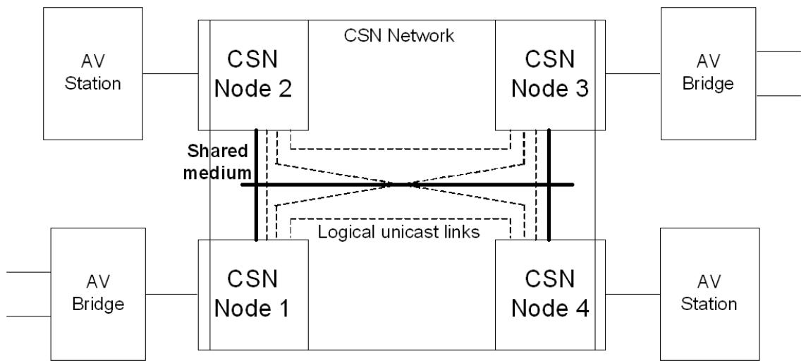
Figure C-1—CSN backbone
Depending on the CSN technology, the Network Coordinator node either may be a fixed node or may be dynamically selected during normal operation.
C.1.2 DMN handling on CSN
From the bandwidth reservation standpoint a CSN network is modeled as a Bridge as illustrated by Figure C-2. Each node-to-node link is equivalent to a Bridge’s path from an ingress port to an egress port.
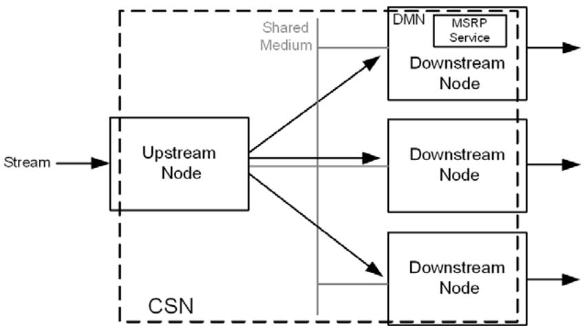
Figure C-2—Bridge’s CSN model for bandwidth reservation
A CSN shall provide a single entity called the Designated MSRP Node (DMN) (35.1.1), which communicates with the MSRP Service to manage the CSN bandwidth resources for the MSRP streams.
NOTE 1—The MSRP Service supplies both MSRP Attribute Propagation (MAP) for the CSN and MSRP Attribute Declaration (MAD) for each MSRP-aware CSN node.
NOTE 2—An end station node provides an end station MSRP implementation as outlined in 5.18.3. This MSRP implementation is logically on the upper layer side of this interface. This standard expects that an MSRP-aware CSN node will have a single non-CSN interface. If more interfaces are present, they are expected to be connected through a Bridge function. If this node happens to be the DMN, then this end station MSRP implementation is separate and distinct from the DMN's MSRP Service.
C.1.2.1 DMN selection and migration
Depending on the CSN technology, the DMN might correspond to a static node or dynamically migrate between nodes during normal operation. The DMN selection is network specific and described in C.2.1 and C.3.2.
Over time the DMN constructs its database by handling the MSRP Talker and Listener Declarations generated by the nodes of the CSN. If the DMN migrates, the new DMN broadcasts an MRP LeaveAll message to all the nodes of the CSN which will force its neighbors to redeclare their attributes. The MSRP Participant nodes answer the MRP LeaveAll message by sending an MRP JoinIn message consumed by the DMN as an MRP Re-Declare! message. These redeclarations permit the new DMN to immediately build its database.
C.1.3 MSRPDU handling on a CSN
Figure C-3 and Figure C-4 illustrate the flow and handling of MSRPDU messages on a CSN.
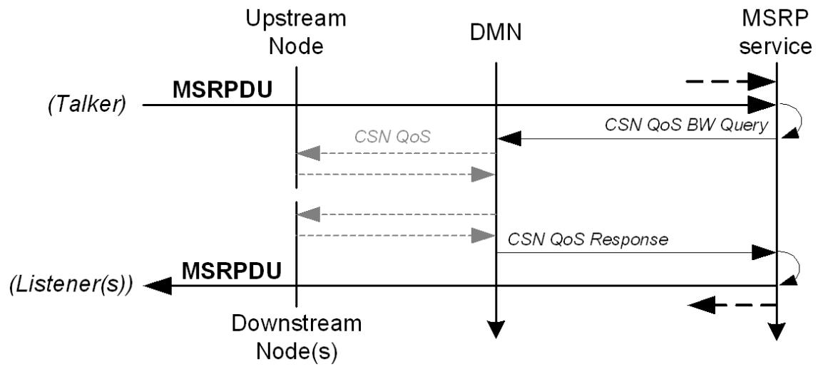
Figure C-3—Talker MSRPDU flow
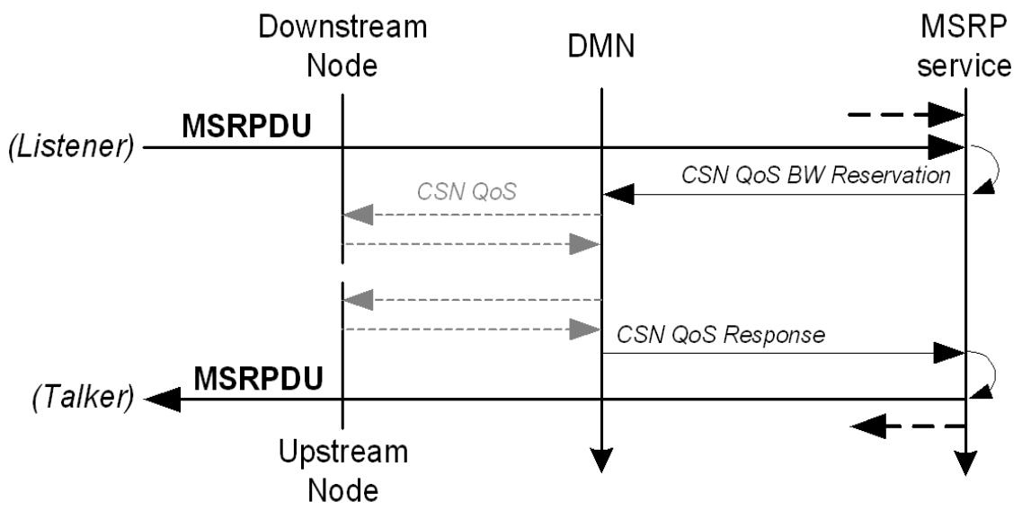
Figure C-4—Listener MSRPDU flow
a) A MSRP-aware CSN node identifies MSRPDUs received on its non-CSN interface (the interface either to another network media or to upper layers of the node) by their destination MAC address (35.2.2.1) and EtherType (35.2.2.2).
b) Non-DMN nodes send MSRPDUs to the DMN over the CSN.
c) The DMN delivers MSRPDUs, along with information about the originating interface, to the MSRP Service.
d) The DMN translates the MSRP TSpec parameters into CSN QoS parameters and invokes the CSN’s Protocol Specific QoS transactions with the CSN Network Coordinator (C.2.2, C.3.3) as follows:
1) When the DMN receives a Talker Advertise message originated from an upstream CSN node, the DMN invokes a bandwidth query transaction with the CSN Network Coordinator to check whether the bandwidth advertised in the message’s TSpec is available on each upstream to downstream node link of the CSN network. In addition the DMN associates the MSRP attributes with the CSN's native QoS records via the StreamID (which is included in the CSN frames). 2) When the DMN receives a Listener Ready message originated from a downstream CSN node, the DMN invokes a bandwidth reservation transaction with the CSN QoS manager to reserve the bandwidth associated with the message’s StreamID on the downstream to upstream CSN node link.
e) After the DMN completes the CSN QoS transactions, the DMN behaves as an MSRP application on a Bridge and propagates (MAP) and distributes (MAD) MSRP attributes (35.2).
NOTE—When the MAD function of the MSRP Service distributes attributes, it will deliver MSRPDUs to the DMN's non-CSN interface and/or send them to the appropriate MSRP-aware CSN nodes.
C.1.4 CSN bandwidth fluctuations
Bandwidth on a CSN may fluctuate depending on interference experienced by the media. The MSRP Attribute Propagation (35.2.4) supports a bandwidthAvailabilityChanged notification when bandwidth increases or decreases across the media. When a bandwidth changed is encountered, MAP will reassess reservation requests to maintain appropriate bandwidth utilization.
C.2 DMN on MoCA
NOTE—The discussion that follows is based on terminology found in the MoCA MAC/PHY Specifications v1.1 and v2.0 [B48] and [B49].
C.2.1 DMN Selection on MoCA Network
C.2.1.1 DMN-capable node discovery
A DMN-capable node shall append the IEEE DMN Device Attribute Information Element (C.2.1.2) to the L2ME payload of the Device Discovery Protocol SUBMIT L2ME transaction message specified in the MoCA MAC/PHY Specification v2.0 [B49].
Upon completion of the L2ME Device Discovery transaction all the DMN-capable nodes of the MoCA network share the same information as follows:
a) which MoCA nodes are DMN capable,
b) which MoCA node is selected as the DMN.
If no DMN is selected, the DMN selection shall be performed (C.2.1.3).
C.2.1.2 IEEE DMN Device Attribute IE
C.2.1.2.1 General
The fields of the IEEE DMN Device Attribute IE are specified in Figure C-5 and C.2.1.2.2 through C.2.1.2.7. The general format of the Device Attribute Information Element is described in the MoCA MAC/ PHY Specification v2.0 [B49].
<table><tr><td colspan="8">Bits</td><td>Octets</td><td rowspan="2">Offset From Start of IE</td></tr><tr><td>8</td><td>7</td><td>6</td><td>5</td><td>4</td><td>3</td><td>2</td><td>1</td><td></td></tr><tr><td colspan="8">ATTRIBUTE_ID</td><td>1</td><td>0</td></tr><tr><td colspan="8">LENGTH</td><td>1</td><td>1</td></tr><tr><td colspan="8">VENDOR_ID</td><td>2</td><td>2</td></tr><tr><td colspan="8">TLV_TYPE</td><td>1</td><td>4</td></tr><tr><td colspan="8">TLV_LENGTH</td><td>1</td><td>5</td></tr><tr><td colspan="8">TLV_VALUE</td><td>2</td><td>6</td></tr></table>
Figure C-5—IEEE DMN Device Attribute IE
C.2.1.2.2 ATTRIBUTE_ID (Enumeration8)
The value of the ATTRIBUTE_ID is 0xFF.
C.2.1.2.3 LENGTH (UInteger8)
The value of the LENGTH is 1.
NOTE—The actual length of the Attribute IE in bits is (LENGTH + 1 ) × 32.
C.2.1.2.4 VENDOR_ID (Enumeration16)
The value of VENDOR_ID is 0x0090 (IEEE 802.1 AVB).
C.2.1.2.5 TLV_TYPE (Enumeration16)
The value of the TLV_TYPE is 1 (SRP).
C.2.1.2.6 TLV_LENGTH (UInteger8)
The length of the TLV in octets is 4.
C.2.1.2.7 TLV_VALUE (Octet2)
The meaning of the field of the TLV_VALUE are specified as described in C.2.1.2.7.1 through C.2.1.2.7.3.
C.2.1.2.7.1 DMNcapable (Bit 0 - Boolean)
A value of 1 indicates the node is capable of acting as the DMN of the network. A value of 0 indicates the node is not capable to act as a DMN.
C.2.1.2.7.2 DMNselected (Bit 1 - Boolean)
A value of 1 indicates the node has been selected as the DMN of the network. A value of 0 indicates the node is not the selected DMN.
C.2.1.2.7.3 Reserved (Bit 2..15)
These bits are reserved for future usage.
C.2.1.3 DMN selection and confirmation
If either 1) the NODE_BITMASK field into MAP frames indicates that the selected DMN has been removed from the network (due to failure, power state/down, etc.) or 2) the DMN node discovery (C.2.1.1) does not indicate a DMN selected node, the DMN-capable node with the lowest node ID will start acting as the DMN and confirm the selection to the other DMN-capable nodes by generating a L2ME DMN Confirmation Transaction (C.2.1.3.1).
NOTE—”MAP frame” is defined in the MoCA MAC/PHY Specification v1.1 [B48].
C.2.1.3.1 L2ME DMN Confirmation Transaction
C.2.1.3.1.1 Overview of DMN Confirmation Transaction
Figure C-6 provides an overview of the signals exchanged among the nodes during an L2ME DMN Confirmation Transaction. As shown in the figure, the NC node starts the transaction either when it receives a Submit L2ME Frame from a node (called the DMN Selected Entry Node for that Transaction) or on its own. The transaction includes two L2ME Waves. The details of each message exchanged during the DMN Confirmation Transaction are provided below.
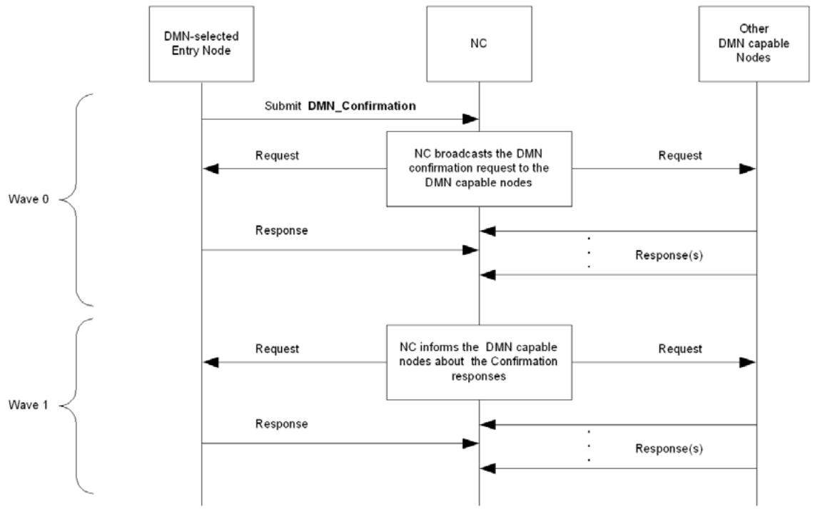
Figure C-6—DMN Confirmation Transaction
C.2.1.3.1.2 DMN Confirmation Submit
The DMN Confirmation Transaction starts when the DMN Selected Entry Node sends a Submit L2ME Frame to the NC.
The general fields of the Submit L2ME frame are as specified in section 2.2.3.1 of the MoCA MAC/PHY Specification v1.1 [B48]. The parameters in the Submit L2ME Frame are set as follows:
a) VENDOR_ID (see C.2.1.2.4)
b) TRANS_TYPE = 0x1 (SRP)
c) TRANS_SUBTYPE = 0x1 (DMN Confirmation)
d) WAVE0_NODEMASK = (DMN-capable nodes)
e) MSG_PRIORITY = 0xF0
f) TXN_LAST_WAVE_NUM = 0x1
g) L2ME_PAYLOAD = 0 bytes
C.2.1.3.1.3 Request L2ME Frame of Wave 0 of DMN Confirmation Transaction
In the Wave 0 that follows the DMN Confirmation Submit message, the NC node initiates a Request L2ME Frame based on the Submit L2ME Frame.
The general fields of the Resquest L2ME frame are as specified in section 2.2.3.2 of the MoCA MAC/PHY Specification v1.1 [B48].
C.2.1.3.1.4 Response L2ME Frame of Wave 0 of DMN Confirmation Transaction
Each of the requested DMN-capable nodes sends a Response L2ME Frame to acknowledge the confirmation request.
The general fields of the Response L2ME frame are as specified in section 2.2.3.3 of the MoCA MAC/PHY Specification v1.1 [B48]. The parameters in the Response L2ME Frame are set as follows:
a) RESP_STATUS <INTERPRETED> = ’1’
b) RESP_STATUS <IN_NEXT_WAVE> = ’1’
c) L2ME_PAYLOAD = 0 bytes
C.2.1.3.1.5 Request L2ME Frame of Wave 1 of DMN Confirmation Transaction
In Wave 1, the NC node informs the DMN-capable nodes about the acknowledgment results from Wave 0. The NC node initiates Wave 1 using a Request L2ME Frame with the “concatenated” type of L2ME_PAYLOAD.
The general fields of the Request L2ME frame are as specified in section 2.2.3.1 of the MoCA MAC/PHY Specification v1.1 [B48]. The “concatenated“ L2ME_Payload is as specified in Table 2-4 of the MoCA MAC/PHY Specification v1.1 [B48].
C.2.1.3.1.6 Response L2ME Frame of Wave 1 of DMN Confirmation Transaction
The DMN Confirmation Transaction is completed when the DMN Selected Entry node and the other DMNcapable nodes send their final Response L2ME Frame to the NC node.
The general fields of the Response L2ME frame are as specified in section 2.2.3.3 of the MoCA MAC/PHY Specification v1.1 [B48]. The parameters in the Response L2ME Frame are set as follows:
a) RESP_STATUS <INTERPRETED> = ’1’
b) RESP_STATUS <IN_NEXT_WAVE> = ’0’
c) L2ME_PAYLOAD = 0 bytes
C.2.2 MoCA network bandwidth management
The MSRP service within the MoCA network manages the MoCA bandwidth for the MSRP streams by invoking the MoCA native PQoS transactions. The DMN shall map the MSRP Attribute Declaration and the resultant MAD declarations as described in Table C-1.
Table C-1—SRP to MoCA PQoS Transaction mapping
<table><tr><td>MSRP Attribute</td><td>MAD Primitive</td><td>MoCA PQoS Transactions</td><td>Description</td></tr><tr><td>Talker Advertise</td><td>MAD_Join.request(new)</td><td>Create PQoS Flow</td><td>Query bandwidth without reservation (see NOTE)</td></tr><tr><td>Listener Ready or Listener Ready Failed</td><td>MAD_Join.request(new)</td><td>Create PQoS Flow</td><td>Reserve bandwidth for a stream</td></tr><tr><td>Listener Ready or Listener Ready Failed</td><td>MAD_Join.request()</td><td>Update PQoS Flow</td><td>Renew the bandwidth reservation (leased time) for a stream</td></tr><tr><td>Talker or Listener Leave</td><td>MAD_Leave.request()</td><td>Delete PQoS Flow</td><td>Free bandwidth associated with a stream</td></tr><tr><td colspan="4">NOTE—MoCA PQoS APIs do not include a Bandwidth Query-specific API. Therefore, bandwidth is queried by invoking a CreatePQoSFlow reservation for more bandwidth than the network could provide. The request will fail and CreatePQoSFlow will then return a failure status that includes the bandwidth available for reservations.</td></tr></table>
Table C-2 describes the mapping between SRP TSpec components and MoCA PQoS TSPEC parameters.
Table C-2—SRP TSpec to MoCA TSPEC mapping
<table><tr><td>SRP TSpec</td><td>MoCA PQoS TSPEC</td></tr><tr><td>MaxFrameSize</td><td>Max Packet Size</td></tr><tr><td>MaxFrameSize × MaxIntervalFrames</td><td>Peak Data Rate</td></tr><tr><td>MaxFrameSize × MaxIntervalFrames × Class B class measurement interval (34.4)</td><td>(Max) Burst Size</td></tr></table>
Table C-3 describes the mapping of the SRP StreamID to MoCA PQoS Flow transactions. The MoCA Flow parameters includes a 32-bit field that allows an application, like SRP, to store application-specific information. SRP will use this field (FLOW_TAG) to store the 16-bit unique ID portion of the StreamID.
Table C-3—SRP StreamID to MoCA PQoS Flow transaction mapping
<table><tr><td rowspan="2">SRP StreamID</td><td colspan="3">MoCA PQoS Flow Transaction</td></tr><tr><td>Transaction</td><td>L2ME Payload</td><td>Field</td></tr><tr><td rowspan="2">EUI-48 MAC Address</td><td>Create PQoS FlowUpdate PQoS Flow</td><td>Submit</td><td rowspan="2">PACKET_DA</td></tr><tr><td>Query PQoS Flow</td><td>Response</td></tr><tr><td rowspan="2">16-bit Unique ID</td><td>Create PQoS FlowUpdate PQoS Flow</td><td>Submit</td><td rowspan="2">FLOW_TAG</td></tr><tr><td>Query PQoS Flow</td><td>Response</td></tr></table>
C.3 DMNs on IEEE 802.11 media
NOTE—Even though IEEE Std 802.11 is not a CSN, it uses the same DMN concepts described below.
From the bandwidth reservation standpoint an IEEE 802.11 BSS network is modeled as a Bridge as illustrated by Figure C-7, Figure C-8, and Figure C-9. Each STA-AP link, STA-AP-STA link and optional STA-STA DLS direct link is equivalent to the path from an input to an output Bridge’s port.
An IEEE 802.11 BSS provides a single entity called the Designated MSRP Node (DMN) (35.1.1) to manage the BSS bandwidth resources for the MSRP streams.
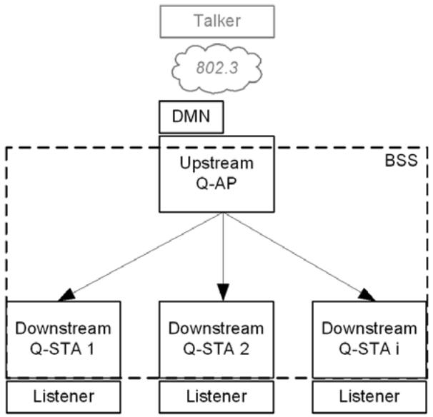
Figure C-7—Bandwidth reservation—bridge model for IEEE 802.11 BSS (STA downstream Port)
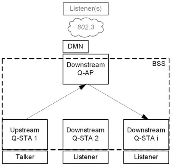
Figure C-8—Bandwidth reservation—bridge model for IEEE 802.11 BSS (STA upstream Port)
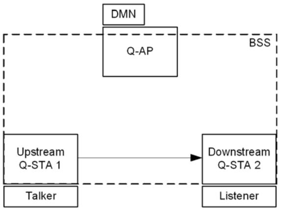
Figure C-9—Bandwidth reservation—bridge model for IEEE 802.11 BSS (direct link setup)
C.3.1 MSRP handling
MSRPDUs are transparently transported by the IEEE 802.11 BSS network and delivered to the DMN.
The DMN maps the MSRP commands into IEEE 802.11 MLME TS commands and interacts with the AP through the AP’s MLME SAP.
Figure C-10 through Figure C-13 describe the flow of information between the MSRP and IEEE 802.11 entities, and corresponding over the air IEEE 802.11 frames. Figure C-10 is an example of the IEEE 802.11 bandwidth query process associated with an MSRP Talker Advertise.
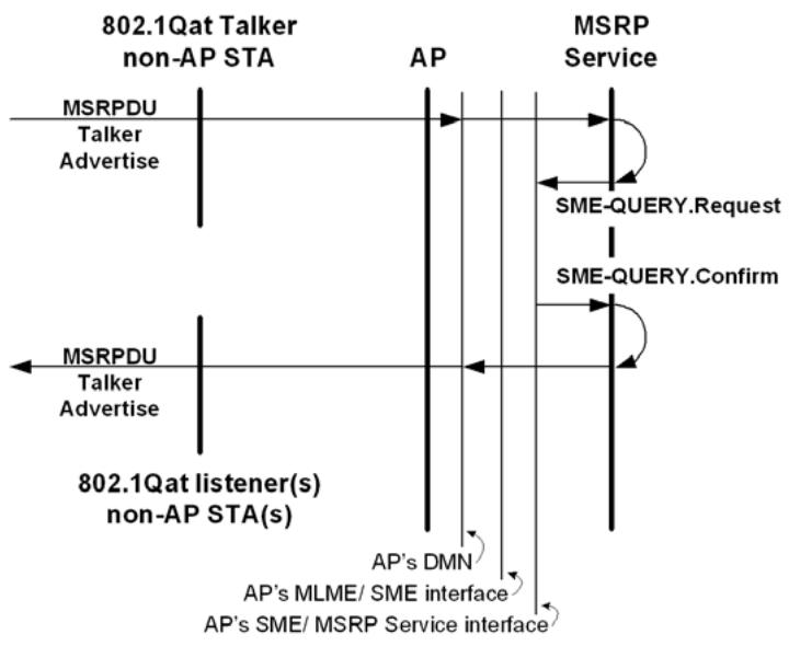
Figure C-10—MSRP/IEEE 802.11 query flows
Figure C-10 is an example of the reservation process associated with a Listener non-AP STA requesting a Stream from the Talker non-AP STA. The diagram at the left of the figure shows the Listener non-AP STA sending a Listener Ready (A) through the AP’s MSRP Service, which then propagates that Listener Ready (B) to the Talker non-AP STA. The message flow on the right of the figure shows the corresponding IEEE 802.11 message exchanges associated with the two Listener Readys (A & B).
There are two reservations (A & B) required to allow the Stream to flow from Talker to Listener. In Figure C-11, Figure C-12 and Figure C-13 the reservation process must be an atomic operation so if either reservation fails then both reservations shall be removed and the MSRP attributes updated accordingly.
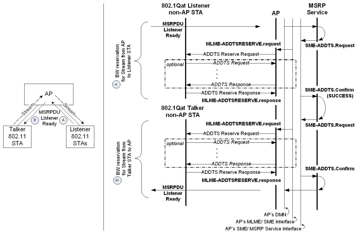
Figure C-11—MSRP/802.11 Talker STA to Listener STA reservation flows
Figure C-12 is an example of the reservation process associated with a “Bridged” Listener requesting a Stream from a Talker non-AP STA. The Listener sends a Listener Ready (A) from the “Bridged” side of the network and bandwidth is reserved as explained in SRP (Clause 35). The IEEE 802.11 message exchanges associated with the Listener Ready (B) propagating to the Talker non-AP STA are also shown.
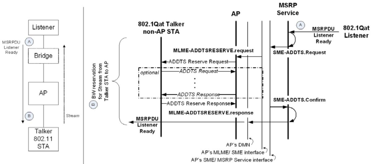
Figure C-12—MSRP/802.11 “Bridged” Listener to Talker STA reservation flows
Figure C-13 is an example of the reservation process associated with a Listener non-AP STA requesting a Stream from a “Bridged” Talker. The Listener non-AP STA sends a Listener Ready (A) through the AP’s MSRP Service, resulting in the IEEE 802.11 message exchanges shown. The reservation process associated with the Listener Ready (B) sent to the “Bridged” Talker is explained in SRP (Clause 35).
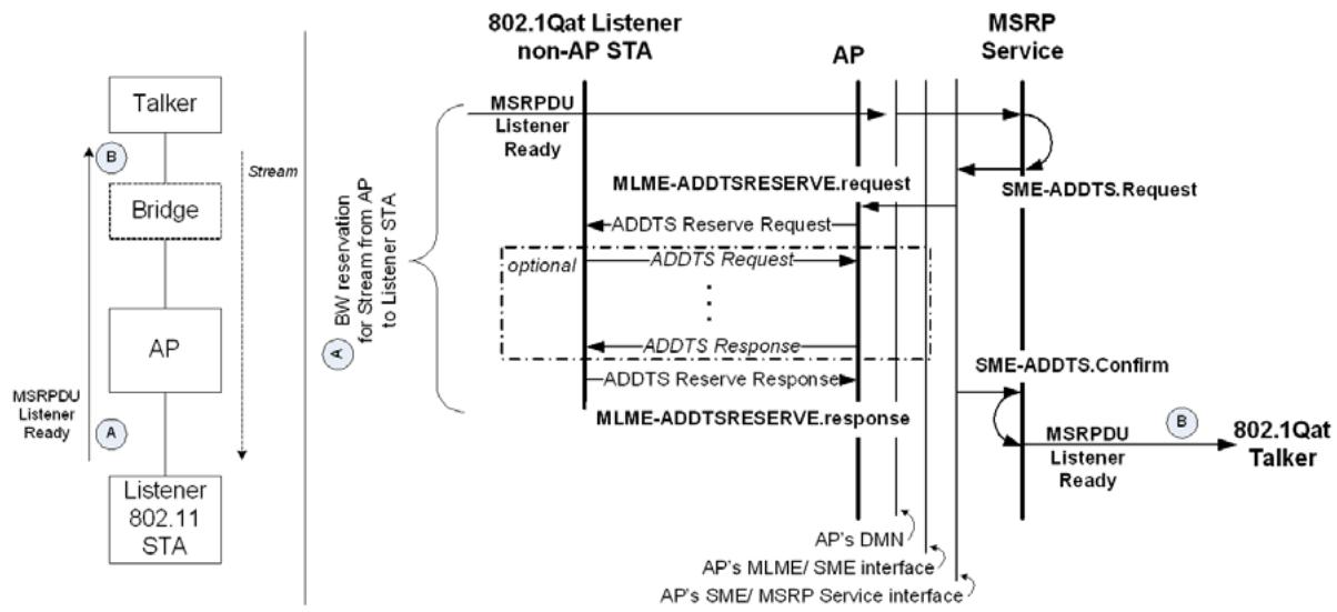
Figure C-13—MSRP/802.11 Listener STA to “Bridged” Talker reservation flows
The IEEE 802.11 message exchanges shown in the preceding three figures are explained in more detail as follows:
a) BBS nodes identify MSRPDUs by their Group Destination Address (35.2.2.1) and EtherType (35.2.2.2) and send these PDUs to the AP.
b) The AP forwards the MSRPDUs to the MSRP service on the DMN.
c) The DMN translates the MSRP TSpec parameters into an equivalent IEEE 802.11 TSPEC and invokes DMN-SME interface primitives with the AP as follows:
1) When the DMN receives a Talker Advertise message that originated from an upstream BSS node, the DMN invokes QoS Query transactions (SME-QUERY.Request) with the BSS QoS AP (i.e., HC where dot11RobustAVStreamingImplemented is true) to check whether the bandwidth advertised in the message’s TSpec is available on each upstream to downstream node link of the BSS. In addition the DMN maps the MSRPDU’s TSpec with the message’s StreamID.
2) When the DMN receives a Listener Ready message originated from a downstream BSS node, the DMN invokes a QoS Reservation transaction (SME-ADDTS.Request) with the BSS QoS manager to reserve the bandwidth associated with the message’s StreamID on the downstream to upstream BSS node link.
The IEEE 802.11 BSS QoS AP on receipt of a SME-ADDTS.Request from the DMN shall make a determination about whether to accept the request or deny the request. The algorithm to be used by the BSS QoS AP to make this determination is an implementation detail.
If the BSS QoS AP decides to accept the request, the AP shall derive a medium time value from the parameters specified in the SME-ADDTS.Request. The BSS QoS AP shall then generate an ADDTS Reserve Request frame in which the medium time value is included and transmit it to the appropriate SRP Talker (BSS upstream) and Listener (BSS downstream) nodes. The appropriate SRP Talker or Listener node replies to this ADDTS Reserve Request frame with an ADDTS Reserve Response frame indicating if the node accepts the reservation request. One or more ADDTS Request and ADDTS Response frames might be exchanged prior to the ADDTS Reserve Response frame.
If the BSS QoS AP or Listener/Talker node decides to reject the request, it shall respond to the DMN with SME-ADDTS.confirm with a ResultCode of Rejected. The confirm primitive may also include a TSPEC which the BSS QoS AP can accept, if specified in a subsequent SME-ADDTS.request.
NOTE—The TSPEC included in the SME-ADDTS.confirm is based on the result of the negotiations (labeled optional in Figure C-11 through Figure C-13) with the upstream BSS node. As a result the TSPEC included in the SME-ADDTS.confirm may be different from the one in the SME-ADDTS.request from the DMN.
d) After the DMN completes the BSS QoS transactions (SME-QUERY.Confirm or SME-ADDTS.Confirm as appropriate), the DMN behaves as an MSRP application on a Bridge and propagates MSRP attributes (35.2).
C.3.2 BSS DMN selection
The DMN shall be co-located with the device that supports the QoS AP function in the BSS.
C.3.3 BSS network bandwidth management
The MSRP service within the IEEE 802.11 network manages the BSS bandwidth for the MSRP streams by invoking the MLME QoS services. The DMN shall map the MLME services as described in Table C-4.
Table C-4—SRP to MLME QoS Services mapping
<table><tr><td>MSRP Attribute</td><td>MAD Primitive</td><td>SME QoS Services</td><td>Description</td></tr><tr><td>Talker Advertise</td><td>MAD_Join.request(new)</td><td>SME-QUERY</td><td>Query bandwidth without reservation</td></tr><tr><td>Listener Ready or Listener Ready Failed</td><td>MAD_Join.request(new)</td><td>SME-ADDTS</td><td>Reserve bandwidth for a stream</td></tr><tr><td>Listener Ready or Listener Ready Failed</td><td>MAD_Join.request()</td><td>SME-ADDTSa</td><td>Renew the bandwidth reservation (leased time) for a stream</td></tr><tr><td>Talker or Listener Leave</td><td>MAD_Leave.request()</td><td>SME-DELTS</td><td>Free bandwidth associated with a stream</td></tr></table>
a Bandwidth renewal is not required as long as the reservation is already established.
C.3.3.1 MSRPDU Encapsulation/De-encapsulation
In order to preserve the priority of an MSRPDU when traversing through a IEEE 802.11 network, the priority shall be encapsulated while the MSRPDU is in the IEEE 802.11 network and shall be deencapsulated as it exits. See IEEE Std 802.11-2012 [B12] for additional information.
NOTE—For example if the priority of the MSRPDU is 4, DEI=0 and VID = 1893 the equivalent VLAN tag field (32 bits) is 81-00-87-65. When the frame enters the IEEE 802.11 network, the encapsulated 802.11 LLC header is AA-AA-03-00-00-00-81-00-87-65-AA-AA-03-00-00-00-08-00, where AA-AA-03-00-00-00-00-81-00-87-65 is the SNAP encoded VLAN header. When the frame exits the IEEE 802.11 network a de-encapsulation operation is performed and the resulting VLAN tag field is 81-00-87-65.
C.3.3.2 QoS Maintenance Report
An SRP DMN may obtain QoS Maintenance Report using IEEE 802.11 Transmit Stream/Category Measurement Requests and processing the corresponding Transmit Stream/Category Measurement Reports. The Transmit Stream/Category Measurement Request is sent to both the SRP Talker (BSS upstream) and the SRP Listener (BSS downstream) nodes. Triggers are set on appropriate conditions such that Transmit Stream/Category Measurement Reports are generated only when predefined thresholds are breached. See IEEE Std 802.11-2012 [B12], 7.3.2.21.10, for details.
NOTE—This provides an indication to SRP (35.2.4) that bandwidth has changed.
C.3.3.3 SRP TSpec to IEEE 802.11 TSPEC mapping
SR Class B traffic has three parameters associated with it, namely delay budget per IEEE 802.11 hop (20 ms), MaxFrameSize (≤1500 bytes) and MaxIntervalFrames (units of 4000 frames per second). IEEE 802.11 TSPECs include a Minimum PHY rate that is derived from the SR Class B parameters as described below:
a) Overhead = 10-byte VLAN tag + 8 byte Protocol definition = 18 bytes.
b) Mean Data $\mathrm { R a t e } \ = \ ( \mathrm { S R P }$ TSpec MaxFrameSize + overhead) $\times \quad 4 0 0 0 \quad \times \quad \mathrm { S R P }$ TSpec MaxIntervalFrames bytes/sec.
c) The Mean Data Rate is also the Max Data Rate (since it is assumed that MSDU size is fixed).
d) Assuming 70% × efficiency between the MAC and the PHY this translates into (10/7) × (SRP TSpec MaxFrameSize + overhead) $\times ~ 4 0 0 0 ~ \times ~ \mathrm { S R P }$ TSpec MaxIntervalFrames bytes/sec, or $( 1 0 / 7 ) \times 8 \times$ (SRP TSpec MaxFrameSize + overhead) × 4000 × SRP TSpec MaxIntervalFrames bits/sec.
e) Minimum PHY Rate is therefore (10/7) × 8 × (SRP TSpec MaxFrameSize + overhead) × 4000 × SRP TSpec MaxIntervalFrames bits/sec.
NOTE—For example, with 1500 and 1 for MaxFrameSize and MaxIntervalFrames the above turns into 69.394285 Mb/s. Or, with 64 and 1 for MaxFrameSize and MaxIntervalFrames the above turns into 3.748571 Mb/s
Table C-5 describes the mapping between SRP TSpec components and IEEE 802.11 QoS TSPEC parameters for the mandatory EDCA-AC mode.
Table C-5—EDCA-AC for AV Streams
<table><tr><td colspan="2">TSPEC Parameter</td><td>SR Class B</td></tr><tr><td rowspan="7">TSINFO</td><td>TID</td><td>5</td></tr><tr><td>Direction</td><td>Up, Down</td></tr><tr><td>Access Policy</td><td>10 (EDCA)</td></tr><tr><td>ACK Policy</td><td>10 (No Ack) / 11 (Block Ack)</td></tr><tr><td>APSD</td><td>0</td></tr><tr><td>Aggregation</td><td>Yes</td></tr><tr><td>Priority</td><td>5</td></tr><tr><td colspan="2">Nominal MSDU <eq>Size^a</eq></td><td>SRP TSpec MaxFrameSize + 18 (also set bit 15 to a 1)</td></tr><tr><td colspan="2">Maximum MSDU Size</td><td>SRP TSpec MaxFrameSize + 18</td></tr><tr><td colspan="2">Peak Data Rate</td><td>(SRP TSpec MaxFrameSize + 18) × 4000 × SRP TSpec MaxIntervalFrames</td></tr><tr><td colspan="2">Minimum PHY <eq>Rate^b</eq></td><td>(10/7) × 8 × (SRP TSpec MaxFrameSize + 18) × 4000 × SRP TSpec MaxIntervalFrames</td></tr><tr><td colspan="2">Delay Bound</td><td>20 ms</td></tr><tr><td colspan="2"><eq>Surplus Bandwidth Allowance^c</eq></td><td>1.2</td></tr></table>
a bit15 set to indicate that the MSDU size is fixed.
b Assuming 70% efficiency between the MAC and the PHY.
c 20% surplus allocation.
Table C-6 describes the mapping between SRP TSpec components and IEEE 802.11 QoS TSPEC parameters for the optional HCCA mode.
Table C-6—HCCA for AV Streams
<table><tr><td colspan="2">TSPEC Parameter</td><td>SR Class B</td></tr><tr><td rowspan="7">TSINFO</td><td>TID</td><td>5</td></tr><tr><td>Direction</td><td>Up, Down</td></tr><tr><td>Access Policy</td><td>01 (HCCA)</td></tr><tr><td>ACK Policy</td><td>10 (No Ack) / 11 (Block Ack)</td></tr><tr><td>APSD</td><td>0</td></tr><tr><td>Aggregation</td><td>Yes</td></tr><tr><td>Priority</td><td>5</td></tr><tr><td colspan="2">Nominal MSDU <eq>Size^a</eq></td><td>0</td></tr><tr><td colspan="2">Maximum MSDU Size</td><td>SRP TSpec MaxFrameSize + 18</td></tr><tr><td colspan="2">Minimum Service Interval</td><td>10 ms</td></tr><tr><td colspan="2">Maximum Service Interval</td><td>10 ms</td></tr><tr><td colspan="2">Inactivity Interval</td><td>0</td></tr><tr><td colspan="2">Minimum Data Rate</td><td>0</td></tr><tr><td colspan="2">Mean Data Rate</td><td>0</td></tr><tr><td colspan="2">Maximum Burst Size</td><td>(SRP TSpec MaxFrameSize + 18) × 4000 × SRP TSpec MaxIntervalFrames × <eq>10^{-2}</eq></td></tr><tr><td colspan="2"><eq>Minimum PHY Rate^b</eq></td><td>(10/7) × 8 × (SRP TSpec MaxFrameSize + 18) × 4000 × SRP TSpec MaxIntervalFrames</td></tr><tr><td colspan="2">Peak Data Rate</td><td>(SRP TSpec MaxFrameSize + 18) × 4000 × SRP TSpec MaxIntervalFrames</td></tr><tr><td colspan="2">Delay Bound</td><td>20 ms</td></tr><tr><td colspan="2"><eq>Surplus Bandwidth Allowance^c</eq></td><td>1.2</td></tr></table>
a bit15 set to indicate that the MSDU size is fixed.
b Assuming 70% efficiency between the MAC and the PHY.
c 20% surplus allocation.
Annex D
(normative)
IEEE 802.1 Organizationally Specific TLVs
D.1 Requirements of the IEEE 802.1 Organizationally Specific TLV sets
The IEEE 802.1 Organizationally Specific TLVs may be supported in conjunction with any of the destination MAC addresses identified in 7.1 of IEEE Std 802.1AB-2009.
If any IEEE 802.1 Organizationally Specific TLV set is supported, all IEEE 802.1 Organizationally Specific TLVs that are identified as members of that TLV set shall be supported. All IEEE 802.1 Organizationally Specific TLVs shall conform to the LLDPDU bit and octet ordering conventions of 8.1 of IEEE Std 802.1AB-2009.
The currently defined IEEE 802.1 Organizationally Specific TLVs specified in this standard are listed in Table D-1. Other standards can also define IEEE 802.1 Organizationally Specific TLVs. The “TLV set name” column identifies the TLV set to which each TLV belongs. Any additions or changes to these TLVs will be included in this annex.
Table D-1—IEEE 802.1 Organizationally Specific TLVs specified in this standard
<table><tr><td>IEEE 802.1 subtype</td><td>TLV name</td><td>TLV set name</td><td>TLV reference</td><td>Feature clause reference</td></tr><tr><td>01</td><td>Port VLAN ID</td><td>basicSet</td><td>D.2.1</td><td>6.9</td></tr><tr><td>02</td><td>Port And Protocol VLAN ID</td><td>basicSet</td><td>D.2.2</td><td>6.12</td></tr><tr><td>03</td><td>VLAN Name</td><td>basicSet</td><td>D.2.3</td><td>12.10.2.1.3</td></tr><tr><td>04</td><td>Protocol Identity</td><td>basicSet</td><td>D.2.4</td><td>D.2.4</td></tr><tr><td>05</td><td>VID Usage Digest</td><td>basicSet</td><td>D.2.5</td><td>D.2.5</td></tr><tr><td>06</td><td>Management VID</td><td>basicSet</td><td>D.2.6</td><td>D.2.6</td></tr><tr><td>07</td><td>Link Aggregation</td><td>basicSet</td><td>D.2.7</td><td>D.2.7, IEEE Std 802.1AX-2008</td></tr><tr><td>08</td><td>Congestion Notification</td><td>cnSet</td><td>D.2.8</td><td>Clause 33</td></tr><tr><td>09</td><td>ETS Configuration TLV</td><td>dcbxSet</td><td>D.2.9</td><td>Clause 38</td></tr><tr><td>0A</td><td>ETS Recommendation TLV</td><td>dcbxSet</td><td>D.2.10</td><td>Clause 38</td></tr><tr><td>0B</td><td>Priority-based Flow Control Configuration TLV</td><td>dcbxSet</td><td>D.2.11</td><td>Clause 38</td></tr><tr><td>0C</td><td>Application Priority TLV</td><td>dcbxSet</td><td>D.2.12</td><td>Clause 38</td></tr><tr><td>0D</td><td>EVB TLV</td><td>evbSet</td><td>D.2.13</td><td>D.2.13</td></tr><tr><td>0E</td><td>CDCP TLV</td><td>evbSet</td><td>D.2.14</td><td>D.2.14</td></tr></table>
D.2 Organizationally Specific TLV definitions
In the TLV definitions that follow, any fields that are labeled as “Reserved” are transmitted as zero and ignored on receipt.
NOTE—In the case of a Port supported by Link Aggregation (IEEE Std 802.1AX), these TLVs apply to the aggregation, not the individual links. Since sending multiple copies is allowed, an implementation can send these TLVs with the same values on each individual link, but a TLV received on any individual link applies to the aggregation.
D.2.1 Port VLAN ID TLV
The Port VLAN ID TLV is an optional fixed length TLV that allows a VLAN Bridge Port to advertise the port VLAN identifier (PVID) that is associated with untagged or priority tagged frames (see 6.9).
Figure D-1 shows the Port VLAN ID TLV format.
<table><tr><td rowspan="2">Octets:</td><td colspan="2">1</td><td colspan="2">2</td><td colspan="2">3</td><td colspan="2">6</td><td>7</td><td>8</td></tr><tr><td colspan="2">TLV type = 127 (7 bits)</td><td colspan="2">TLV information string length = 6 (9 bits)</td><td colspan="2">802.1OUI 00-80-C2 (3 octets)</td><td colspan="2">802.1 subtype = 1 (1 octet)</td><td colspan="2">port VLAN identifier (PVID) (2 octets)</td></tr><tr><td>Bits:</td><td>8</td><td>2</td><td>1</td><td>8</td><td>1</td><td></td><td></td><td></td><td></td><td></td></tr></table>
Figure D-1—Port VLAN ID TLV format
D.2.1.1 port VLAN identifier (PVID)
The PVID field shall contain the VID for the Bridge Port as defined in 6.9. A value of zero shall be used if the system either does not know the PVID or does not support Port-based VLAN operation.
D.2.1.2 Port VLAN ID TLV usage rules
An LLDPDU should contain no more than one Port VLAN ID TLV.
D.2.2 Port And Protocol VLAN ID TLV
The Port And Protocol VLAN ID TLV is an optional TLV that allows a Bridge Port to advertise a port and protocol VLAN identifier (PPVID). Figure D-2 shows the Port And Protocol VLAN ID TLV format.
<table><tr><td rowspan="2">Octets:</td><td colspan="2">1</td><td colspan="2">2</td><td>3</td><td>6</td><td>7</td><td>8</td><td>9</td></tr><tr><td colspan="2">TLV type = 127 (7 bits)</td><td colspan="2">TLV information string length = 7 (9 bits)</td><td>802.1OUI 00-80-C2 (3 octets)</td><td>802.1 subtype = 2 (1 octet)</td><td>flags (1 octet)</td><td colspan="2">port and protocol VLAN identifier (PPVID) (2 octets)</td></tr><tr><td>Bits:</td><td>8</td><td>2</td><td>1</td><td>8</td><td>1</td><td></td><td></td><td></td><td></td></tr></table>
Figure D-2—Port And Protocol VLAN ID TLV format
D.2.2.1 flags
The flags field shall contain a bit map indicating the port and protocol VLAN capability and status as defined in Table D-2.
Table D-2—Port and protocol capability/status
<table><tr><td>Bit</td><td>Function</td><td>Value/meaning</td></tr><tr><td>0</td><td>Reserved for future standardization</td><td>—</td></tr><tr><td>1</td><td>Port and protocol VLAN supported</td><td>1 = supported0 = not supported</td></tr><tr><td>2</td><td>Port and protocol VLAN enabled</td><td>1 = enabled0 = not enabled</td></tr><tr><td>3–7</td><td>Reserved for future standardization</td><td>(set to zero)</td></tr></table>
D.2.2.2 port and protocol VLAN identifier (PPVID)
The PPVID field shall contain the PPVID number for this IEEE 802 LAN station. If the port is not capable of supporting port and protocol VLANs and/or the port is not enabled with any port and protocol VLAN, the PPVID number should be zero.
D.2.2.3 Port And Protocol VLAN ID TLV usage rules
Port And Protocol VLAN ID TLVs are subject to the following rules:
a) If more than one Port And Protocol VLAN ID TLV is defined for a port, the PPVID value shall be different from any other PPVID defined for the port.
b) If the support bit (bit 1) of the flag field indicates that the port is not capable of supporting port and protocol VLANs but the enabled bit (bit 2) indicates that the port is enabled with one or more port and protocol VLANs, the Port And Protocol VLAN ID TLV is interpreted as containing an error and will be discarded.
c) If the PPVID reference number is greater than 4094, the Port And Protocol VLAN ID TLV is interpreted as containing an error and is discarded.
D.2.3 VLAN Name TLV
The VLAN Name TLV is an optional TLV that allows an IEEE 802.1Q-compatible IEEE 802 LAN station to advertise the assigned name of any VLAN with which it is configured.
Figure D-3 shows the VLAN Name TLV format.
<table><tr><td rowspan="2">Octets:</td><td colspan="2">1</td><td colspan="2">2</td><td>3</td><td>6</td><td>7</td><td>9</td><td>10 9+n</td></tr><tr><td>TLV type = 127 (7 bits)</td><td colspan="3">TLV information string length</td><td>802.1OUI 00-80-C2 (3 octets)</td><td>802.1 subtype = 3 (1 octet)</td><td>VLAN ID (2 octets)</td><td>VLAN name length (1 octet)</td><td>VLAN name (n = 0-32 octets)</td></tr><tr><td>Bits:</td><td colspan="4">8 2 1 8 1</td><td colspan="5"></td></tr></table>
Figure D-3—VLAN Name TLV format
D.2.3.1 TLV information string length
The TLV information string length field shall contain the length, in octets, of the (VLAN name + 7).
D.2.3.2 VLAN ID (VID)
The VLAN ID field shall contain the VID number associated with the VLAN name.
D.2.3.3 VLAN name length
The VLAN name length field shall contain the length, in octets, of the VLAN name. A VLAN name length of zero indicates that there is no VLAN name associated with this VLAN.
D.2.3.4 VLAN name
If present, the VLAN name field shall contain the VLAN’s name. If implementations support IETF RFC 4363, the dot1QVLANStaticName object should be used for this field.
D.2.3.5 VLAN Name TLV usage rules
If more than one VLAN Name TLV is defined for a port, the VID and the associated VLAN name combination shall be different from any other VID and VLAN name combination defined for the port.
D.2.4 Protocol Identity TLV
The Protocol Identity TLV is an optional TLV that allows an IEEE 802 LAN station to advertise particular protocols that are accessible through the port. Figure D-4 shows the protocol identity TLV format.
<table><tr><td rowspan="2">Octets:</td><td colspan="2">1</td><td colspan="2">2</td><td>3</td><td>6</td><td>7</td><td>8</td><td>7+n</td></tr><tr><td colspan="2">TLV type = 127 (7 bits)</td><td colspan="2">TLV information string length</td><td>802.1OUI 00-80-C2 (3 octets)</td><td>802.1 subtype = 4 (1 octet)</td><td colspan="2">protocol identity length (1 octet)</td><td>protocol identity (n<=255 octets)</td></tr><tr><td>Bits:</td><td>8</td><td>2</td><td>1</td><td>8</td><td>1</td><td></td><td></td><td></td><td></td></tr></table>
Figure D-4—Protocol Identity TLV format
D.2.4.1 TLV information string length
The TLV information string length field shall contain the length, in octets, of the (protocol identity + 5).
D.2.4.2 protocol identity length
The protocol identity length field shall contain the length, in octets, of the protocol identity.
D.2.4.3 protocol identity
The protocol identity field shall contain the first n octets of the protocol after the layer 2 addresses (i.e., for example, starting with the EtherType field) that the sender would like to advertise. The value of n is determined by the need for the protocol to disambiguate itself. The protocol information string shall include enough octets to allow the receiver to correctly identify the protocol and its version. To advertise spanning tree protocols, for example, the protocol identity field would need to include at least eight octets:
IEEE 802.3 length (two octets), LLC addresses (two octets), IEEE 802.3 control (one octet), Protocol ID (two octets), and the protocol version (one octet).
D.2.4.4 Protocol Identity TLV usage rules
If more than one Protocol Identity TLV is defined for a port, the protocol identity field value shall be different from any other Protocol Identity TLV defined for the port.
D.2.5 VID Usage Digest TLV
The VID Usage Digest TLV is an optional TLV that allows an IEEE Std 802.1Q-compatible IEEE 802 LAN station to advertise the value of a VID Usage Digest associated with the system. The value of the VID Usage Digest is obtained by applying the CRC32 function (IEEE Std 802.3-2008, 4.2.10) to a VID Usage Table having a fixed length of 512 octets. A bit of the VID Usage Table contains the value PBB-TE-USAGE (binary 1) if the corresponding element of the MST Configuration Table (8.9.1) contains the value PBB-TE MSTID (hex FFE) and otherwise contains the value NON-PBB-TE-USAGE (binary 0).
Figure D-5 shows the VID Usage Digest TLV format.
<table><tr><td rowspan="2">Octets:</td><td colspan="2">1</td><td colspan="2">2</td><td>3</td><td>6</td><td>7</td><td>10</td></tr><tr><td colspan="2">TLV type = 127 (7 bits)</td><td colspan="2">TLV information string length = 8</td><td>802.1OUI 00-80-C2 (3 octets)</td><td>802.1 subtype = 5 (1 octet)</td><td colspan="2">VID usage digest (4 octets)</td></tr><tr><td>Bits:</td><td>8</td><td>2</td><td>1</td><td>8</td><td>1</td><td></td><td></td><td></td></tr></table>
Figure D-5—VID Usage Digest TLV format
D.2.5.1 VID Usage Digest
The VID Usage Digest field shall contain a VID Usage Digest value obtained by applying the CRC32 function to the 512-octet VID Usage Table. A bit of the VID Usage Table contains the value PBB-TE-USAGE (binary 1) if the corresponding element of the MST Configuration Table (8.9.1) contains the value PBB-TE MSTID (hex FFE) and otherwise contains the value NON-PBB-TE-USAGE (binary 0).
D.2.6 Management VID TLV
The Management VID TLV is an optional TLV that allows an IEEE 802.1Q-compatible IEEE 802 LAN station to advertise the value of a Management VID associated with the system.
Figure D-6 shows the Management VID TLV format.
<table><tr><td rowspan="2">Octets:</td><td colspan="2">1</td><td colspan="2">2</td><td>3</td><td>6</td><td>7</td><td>8</td></tr><tr><td colspan="2">TLV type = 127 (7 bits)</td><td colspan="2">TLV information string length = 6</td><td>802.1OUI 00-80-C2 (3 octets)</td><td colspan="2">802.1 subtype = 6 (1 octet)</td><td>Management VID (2 octets)</td></tr><tr><td>Bits:</td><td>8</td><td>2</td><td>1</td><td>8</td><td>1</td><td colspan="3"></td></tr></table>
Figure D-6—Management VID TLV format
D.2.6.1 Management VID
The Management VID field shall contain the value configured for the Management VID, or the value 0 if a Management VID has not been provisioned.
D.2.7 Link Aggregation TLV
The Link Aggregation TLV indicates whether the link is capable of being aggregated, whether the link is currently in an aggregation, as specified in IEEE Std 802.1AX, and if in an aggregation, the port identification of the aggregation. Figure D-7 shows the format for this TLV.
<table><tr><td rowspan="2">Octets:</td><td colspan="2">1</td><td colspan="2">2</td><td>3</td><td>6</td><td>7</td><td>8</td><td>11</td></tr><tr><td>TLV type = 127 (7 bits)</td><td colspan="3">TLV information string length = 9</td><td>802.1OUI 00-80-C2 (3 octets)</td><td>802.1 subtype = 7 (1 octet)</td><td>aggregation status (1 octet)</td><td colspan="2">aggregated port ID (4 octets)</td></tr><tr><td>Bits:</td><td>8</td><td>2</td><td>1</td><td>8</td><td>1</td><td></td><td></td><td></td><td></td></tr></table>
Figure D-7—Link Aggregation TLV format
D.2.7.1 aggregation status
The aggregation status field shall contain a bit map of the Link Aggregation capabilities and the current aggregation status of the link as defined in Table D-3.
Table D-3—Link Aggregation capability/status
<table><tr><td>Bit</td><td>Function</td><td>Value/meaning</td></tr><tr><td>0</td><td>Aggregation capability</td><td>0 = not capable of being aggregated1 = capable of being aggregated</td></tr><tr><td>1</td><td>Aggregation status</td><td>0 = not currently in aggregation1 = currently in aggregation</td></tr><tr><td>2–7</td><td>Reserved for future standardization</td><td>—</td></tr></table>
D.2.7.2 aggregated port ID
The aggregated port ID field shall contain the IEEE 802.3 aggregated port identifier, aAggPortID, derived from the ifNumber in the ifIndex for the interface.
NOTE—This field is meaningful only if the link concerned is currently a member of an aggregation.
D.2.7.3 Link Aggregation TLV usage rules
An LLDPDU should contain no more than one Link Aggregation TLV.
D.2.8 Congestion Notification TLV
The TLV illustrated in Figure D-8 is encoded into each IEEE 802.1AB LLDP message transmitted by a system that is configured to support congestion notification on one or more priority values.
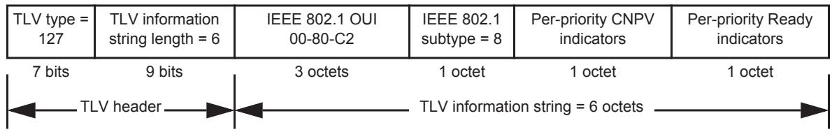
Figure D-8—Congestion Notification TLV format
A system shall transmit no more than one Congestion Notification TLV in a single LLDP PDU. If a system receives an LLDP PDU with more than one Congestion Notification TLV, the behavior of the receiving system is unspecified. A system shall not transmit a Congestion Notification TLV with all of the Per-priority CNPV indicators (D.2.8.3) clear (0).
D.2.8.1 TLV type
A 7-bit integer value occupying the most significant bits of the first octet of the TLV. Always contains the value 127.
D.2.8.2 TLV information string length
A 9-bit unsigned integer, occupying the LSB of the first octet of the TLV (the MSB of the TLV information string length) and the entire second octet of the TLV, containing the total number of octets in the TLV information string of the Congestion Notification TLV. This does not count the TLV type and TLV information string length fields. It is equal to 6.
D.2.8.3 Per-priority CNPV indicators
A bit vector, one per priority value, containing all eight of the cnpdXmitCnpvCapable variables (32.4.7) for this port. The LSB of the octet carries priority 0’s cnpdXmitCnpvCapable variable, and the MSB that of priority 7.
D.2.8.4 Per-priority Ready indicators
A bit vector, one per priority value, containing all eight of the cnpdXmitReady variables (32.4.8) for this port. The LSB of the octet carries priority 0’s cnpdXmitReady variable, and the MSB that of priority 7.
D.2.9 ETS Configuration TLV
The TLV illustrated in Figure D-9 is encoded into each IEEE 802.1AB-2009 LLDP message and may be transmitted by a system in order to indicate the ETS configuration. Shall be sent using Asymmetric attribute passing (38.4.1)
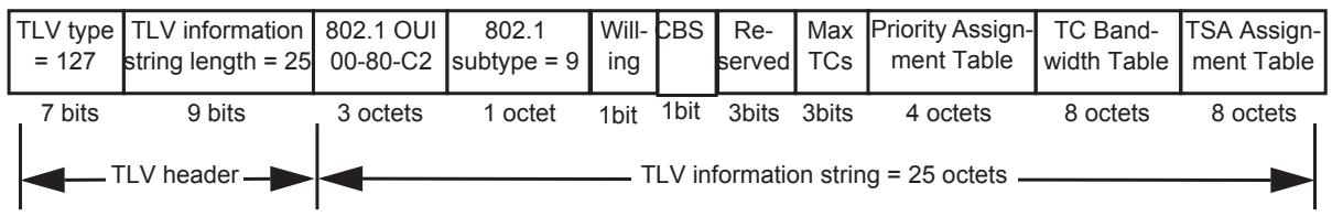
Figure D-9—ETS Configuration TLV format
D.2.9.1 TLV type
A 7-bit integer value occupying the most significant bits of the first octet of the TLV. Always contains the value 127.
D.2.9.2 TLV information string length
A 9-bit unsigned integer, occupying the LSB of the first octet of the TLV (the MSB of the TLV information string length) and the entire second octet of the TLV, containing the total number of octets in the TLV information string of the ETS Configuration TLV. This does not count the TLV type and TLV information string length fields. It is equal to 25.
D.2.9.3 Willing
The Willing bit. A value of one indicates that the station is willing to accept configurations from the remote station.
D.2.9.4 CBS
The Credit-based Shaper (CBS) bit. A value of one indicates that the station supports the Credit-based Shaper transmission selection algorithm (see Table 8-5 and Clause 34).
D.2.9.5 Max TCs
A 3-bit unsigned integer where the value of the integer is the maximum number of traffic classes that the implementation can support with the value 0 used when a device supports 8.
D.2.9.6 Priority Assignment Table
Table D-4 shows the layout of the priority assignment table.
Table D-4—Priority assignment table
<table><tr><td rowspan="2">Octets:</td><td colspan="2">1</td><td colspan="2">2</td><td colspan="2">3</td><td colspan="2">4</td></tr><tr><td>Priority 0</td><td>Priority 1</td><td>Priority 2</td><td>Priority 3</td><td>Priority 4</td><td>Priority 5</td><td>Priority 6</td><td>Priority 7</td></tr><tr><td>Bits:</td><td>7 4</td><td>3 0</td><td>7 4</td><td>3 0</td><td>7 4</td><td>3 0</td><td>7 4</td><td>3 0</td></tr></table>
The table consists of one 4-bit entry per Priority, where
a) 0-7 indicate the Priority is mapped to the corresponding traffic class; and
b) All other values are Reserved.
D.2.9.7 TC Bandwidth Table
Table D-5 shows the layout of the traffic class bandwidth table.
Table D-5—Traffic class bandwidth assignment table
<table><tr><td rowspan="2">Octets:</td><td>1</td><td>2</td><td>3</td><td>4</td><td>5</td><td>6</td><td>7</td><td>8</td></tr><tr><td>TC% 0</td><td>TC% 1</td><td>TC% 2</td><td>TC% 3</td><td>TC% 4</td><td>TC% 5</td><td>TC% 6</td><td>TC% 7</td></tr></table>
The table consists of one 8-bit entry per traffic class, and always contains 8 entries. Each entry:
a) Indicates the current TCBandwidth percentage configured for each traffic class N where N is 0 to 7.
b) Total shall equal 100 (implies valid range is 0-100 for each entry).
NOTE—While it is intended that only TCs configured for ETS will have a bandwidth value associated with them, it is possible, during configuration changes, to have situations where a TC is not configured for ETS but has a nonzero TCBandwidth percentage. In this case, the sum of all the TCBandwidth percentages is still equal to 100, but the TC bandwidth percentages of the non-ETS TCs would be unused bandwidth and reallocated to the ETS TCs.
D.2.9.8 TSA Assignment Table
Table D-6 shows the layout of the Transmission Selection Algorithm (TSA) Assignment Table.
Table D-6—TSA Assignment Table
<table><tr><td rowspan="2">Octets:</td><td>1</td><td>2</td><td>3</td><td>4</td><td>5</td><td>6</td><td>7</td><td>8</td></tr><tr><td>TrafficClass 0</td><td>TrafficClass 1</td><td>TrafficClass 2</td><td>TrafficClass 3</td><td>TrafficClass 4</td><td>TrafficClass 5</td><td>TrafficClass 6</td><td>TrafficClass 7</td></tr></table>
The table consists of one 8-bit entry per traffic class. Each entry indicates the Transmission selection algorithm to be used for that traffic class as defined in Table 8-5. A value of 255 indicates a Vendor-specific Transmission selection algorithm.
D.2.10 ETS Recommendation TLV
The TLV illustrated in Figure D-10 is encoded into each IEEE 802.1AB-2009 LLDP message and may be transmitted by a system in order to indicate a recommendation on how ETS should be configured. A Willing system may receive a recommendation TLV which utilizes more Traffic Classes than the receiving system supports. In this case the receiving system may assign the received recommendations to match its capabilities. Shall be sent using Asymmetric attribute passing (38.4.1).
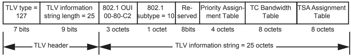
Figure D-10—ETS Recommendation TLV format
D.2.10.1 TLV type
A 7-bit integer value occupying the most significant bits of the first octet of the TLV. Always contains the value 127.
D.2.10.2 TLV information string length
A 9-bit unsigned integer, occupying the LSB of the first octet of the TLV (the MSB of the TLV information string length) and the entire second octet of the TLV, containing the total number of octets in the TLV information string of the ETS Recommendation TLV. This does not count the TLV type and TLV information string length fields. It is equal to 25.
D.2.10.3 Priority Assignment Table
Table D-4 shows the layout of the priority assignment table.
See D.2.9.6 for description of table entries.
D.2.10.4 TC Bandwidth Table
Table D-5 shows the layout of the Traffic Class bandwidth assignment table.
See D.2.9.7 for description of table entries.
D.2.10.5 TSA Assignment Table
Table D-6 shows the layout of the TSA Assignment Table.
See D.2.9.8 for description of table entries.
D.2.11 Priority-based Flow Control Configuration TLV
The TLV illustrated in Figure D-11 is encoded into each IEEE 802.1AB-2009 LLDP message and may be transmitted by a system in order to indicate how PFC should be configured. Shall be sent using Symmetric attribute passing.
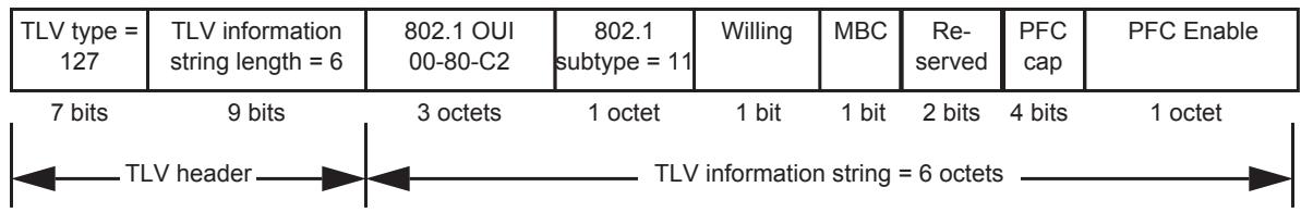
Figure D-11—Priority-based Flow Control Configuration TLV format
D.2.11.1 TLV type
A 7-bit integer value occupying the most significant bits of the first octet of the TLV. Always contains the value 127.
D.2.11.2 TLV information string length
A 9-bit unsigned integer, occupying the LSB of the first octet of the TLV (the MSB of the TLV information string length) and the entire second octet of the TLV, containing the total number of octets in the TLV information string of the Priority-based Flow Control Configuration TLV. This does not count the TLV type and TLV information string length fields. It is equal to 6.
D.2.11.3 Willing
The Willing bit. A value of one indicates that the station is willing to accept configurations from the remote station.
D.2.11.4 MBC
The MACsec Bypass Capability Bit. If set to zero, the sending station is capable of bypassing MACsec processing when MACsec is disabled. If set to one, the sending station is not capable of bypassing MACsec processing when MACsec is disabled (see Clause 36).
D.2.11.5 PFC cap
A 4-bit unsigned integer, PFC cap (PFC capability) indicates the device’s limitation of how many traffic classes may simultaneously support PFC
NOTE 1—PFC may be enabled on up to eight traffic classes allowing each priority to be independently paused.
NOTE 2—In a DCB environment at least one priority would generally have PFC enabled.
D.2.11.6 PFC Enable
Table D-7 shows the layout of the PFC Enable bit vector.
Table D-7—PFC Enable bit vector
<table><tr><td rowspan="2">Octet:</td><td colspan="8">1</td></tr><tr><td>Priority 7</td><td>Priority 6</td><td>Priority 5</td><td>Priority 4</td><td>Priority 3</td><td>Priority 2</td><td>Priority 1</td><td>Priority 0</td></tr><tr><td>Bits:</td><td>7</td><td>6</td><td>5</td><td>4</td><td>3</td><td>2</td><td>1</td><td>0</td></tr></table>
A bit vector of 8 bits, one per priority:
a) A one indicates PFC is enabled on the priority.
b) A zero indicates that PFC is disabled on the priority.
c) Local policy in each end of the link decides whether to use the priority if the configuration does not match.
D.2.12 Application Priority TLV
The TLV illustrated in Figure D-12 is encoded into each IEEE 802.1AB-2009 LLDP message and may be transmitted by a system in order to indicate the application priority table. This TLV is informational and used to indicate to a peer station the local configuration.
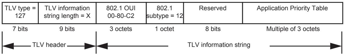
Figure D-12—Application Priority TLV format
D.2.12.1 TLV type
A 7-bit integer value occupying the most significant bits of the first octet of the TLV. Always contains the value 127.
D.2.12.2 TLV information string length
A 9-bit unsigned integer, occupying the LSB of the first octet of the TLV (the MSB of the TLV information string length) and the entire second octet of the TLV, containing the total number of octets in the TLV information string of the Application Priority TLV. This does not count the TLV type and TLV information string length fields. The length for the Application Priority TLV is variable depending on the number of Application Priorities specified. The length shall be 5 plus a multiple of 3 octets.
D.2.12.3 Application Priority Table
Table D-8 shows the layout of the Application Priority Table field.
Table D-8—Application Priority Table
<table><tr><td rowspan="2">Octets:</td><td colspan="4">1</td><td>2</td><td>3</td></tr><tr><td>Priority</td><td>Reserved</td><td colspan="2">Sel</td><td colspan="2">Protocol ID</td></tr><tr><td>Bits:</td><td>23 21</td><td>20 19</td><td colspan="2">18 16</td><td>15</td><td>0</td></tr></table>
The priority field is a 3-bit unsigned integer indicating the priority for which the Protocol ID is being used.
The meaning of the Protocol ID field is determined by the Sel field. Allowed values for the Sel field are shown in Table D-9.
Table D-9—Sel field values
<table><tr><td>Sel Value</td><td>Protocol ID value</td></tr><tr><td>0</td><td>Reserved</td></tr><tr><td>1</td><td>0: Default priority. For use when priority is not otherwise specified.1–1535: Reserved.1536–65535: An Ethertype</td></tr><tr><td>2</td><td>Well Known Port number over TCP, or Stream Control Transmission Protocol (SCTP).</td></tr><tr><td>3</td><td>Well Known Port number over UDP, or Datagram Congestion Control Protocol (DCCP).</td></tr><tr><td>4</td><td>Well Known Port number over TCP, SCTP, UDP, or DCCP.</td></tr><tr><td>5–7</td><td>Reserved</td></tr></table>
NOTE—The port numbers shown are for identification (i.e., as assigned by IANA) instead of the actual port numbers being used in a particular deployment.
D.2.13 EVB TLV
The EVB TLV is used to
a) Advertise a station or Bridge’s EVB capabilities.
b) Negotiate and activate common capabilities.
The EVB TLV is exchanged via LLDP and conforms to the LLDP TLV specification. The LLDP database carrying the EVB TLV is addressed using the Nearest Customer Bridge address. One LLDP database is built at the URP of each ER.
The EVB TLV allows setting the EVB Bridge's C-VLAN component Port to operate in reflective relay. Reflective relay is implemented by changing the active topology enforcement rules described in 8.6.1 to allow forwarding on the reception Bridge Port. When reflective relay is enabled on a given Bridge Port, that port is a potential transmission port for frames received on that port.
The EVB TLV structure is illustrated in Figure D-13.
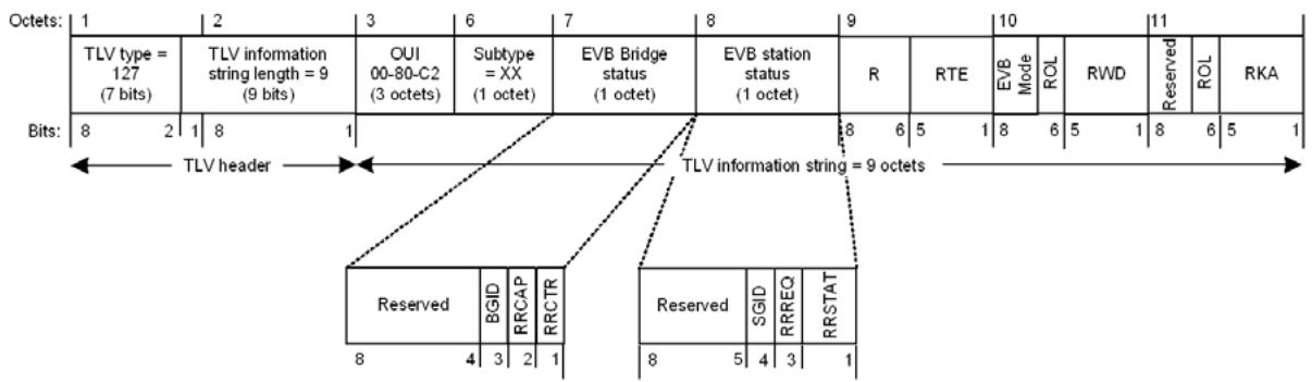
Figure D-13—EVB TLV format
The EVB TLV information string fields are as defined in D.2.13.1 through D.2.13.9.
D.2.13.1 OUI
The OUI used to identify the EVB TLV is the 802.1 OUI 00-80-C2.
D.2.13.2 Subtype
The subtype used to identify the EVB TLV is as shown in Table D-1.
D.2.13.3 EVB Bridge status
The EVB Bridge status field describes EVB capabilities that are supported by the EVB Bridge. If the sender of the TLV is an EVB Bridge (EVB Mode = EVB Bridge—see D.2.13.7), then the field reflects its own capabilities; if the sender of the TLV is an EVB station (EVB Mode = EVB station), then the field reflects the capabilities received from an attached EVB Bridge, or a value of zero if no TLV has been received from an attached EVB Bridge.
Each capability is represented by a single bit flag; a value of TRUE (1) indicates that the capability is supported, a value of FALSE (0) indicates that the capability is not supported.The capabilities are as defined in D.2.13.3.1 through D.2.13.3.3.
D.2.13.3.1 BGID
A value of TRUE indicates that the EVB Bridge wishes to control VID assignments and use the GroupID in VDP exchanges. A value of FALSE indicates that the EVB Bridge does not wish to make use of the Group ID in VDP exchanges.
If the EVB station sets SGID = TRUE, and the EVB Bridge also sets BGID = TRUE, then the EVB Bridge can control VID assignments and use the GroupID in VDP exchanges.
If the EVB station does not set SGID = TRUE, or the EVB Bridge does not set BGID = TRUE, then the EVB Bridge cannot control VID assignments or use the GroupID in VDP exchanges.
D.2.13.3.2 RRCAP
The RRCAP flag indicates the state of the EVB Bridge’s reflectiveRelayCapable parameter (40.4.2).
If the EVB Bridge’s reflectiveRelayCapable parameter is TRUE, and a TLV has been received by the EVB Bridge from an attached EVB station in which the value of RRREQ (D.2.13.4.2) is also TRUE, then the value of the EVB Bridge’s operReflectiveRelayControl parameter (40.4.2) shall be set to TRUE. Otherwise, the value of the EVB Bridge’s operReflectiveRelayControl parameter (40.4.2) shall be set to FALSE.
D.2.13.3.3 RRCTR
The RRCTR flag indicates the state of the EVB Bridge’s operReflectiveRelayControl parameter (40.4.2).
D.2.13.4 EVB station status
The EVB station status field describes EVB capabilities that are supported by the EVB station. If the sender of the TLV is an EVB station (EVB Mode = EVB station—see D.2.13.7), then the field reflects its own capabilities; if the sender of the TLV is an EVB Bridge (EVB Mode = EVB Bridge), then the field reflects the capabilities received from an attached EVB station, or a value of zero if no TLV has been received from an attached EVB station.
Each capability is represented by a single bit flag; a value of TRUE (1) indicates that the capability is supported, a value of FALSE (0) indicates that the capability is not supported.The capabilities are as defined in D.2.13.3.1 through D.2.13.3.3.
D.2.13.4.1 SGID
A value of TRUE indicates that the EVB station can support the use of the GroupID.
If the EVB station sets SGID = TRUE, and the EVB Bridge also sets BGID = TRUE, then the EVB Bridge can control VID assignments and use the GroupID in VDP exchanges.
If the EVB station does not set SGID = TRUE, or the EVB Bridge does not set BGID = TRUE, then the EVB Bridge cannot control VID assignments or use the GroupID in VDP exchanges.
D.2.13.4.2 RRREQ
The RRREQ flag indicates the state of the EVB station’s adminReflectiveRelayRequest parameter (40.4.3).
D.2.13.4.3 RRSTAT
RRSTAT is a composite flag that indicates the state of the EVB station’s operReflectiveRelayStatus parameter (40.4.3) as shown in Table D-10.
Table D-10—RRSAT flag values and meanings
<table><tr><td>Bit 1</td><td>Bit 2</td><td>Meaning</td></tr><tr><td>TRUE</td><td>FALSE</td><td>operReflectiveRelayStatus is TRUE</td></tr><tr><td>FALSE</td><td>FALSE</td><td>operReflectiveRelayStatus is FALSE</td></tr><tr><td>TRUE</td><td>TRUE</td><td>operReflectiveRelayStatus is Unknown</td></tr><tr><td>FALSE</td><td>TRUE</td><td>operReflectiveRelayStatus is Unknown</td></tr></table>
If a TLV has been received by the EVB station from an attached EVB Bridge in which the value of RRCTR (D.2.13.3.3) is TRUE, then the value of the EVB station’s operReflectiveRelayStatus parameter (40.4.3) shall be set to TRUE. If a TLV has been received by the EVB station from an attached EVB Bridge in which the value of RRCTR (D.2.13.3.3) is FALSE, then the value of the EVB station’s operReflectiveRelayStatus parameter (40.4.3) shall be set to FALSE. If no TLV has been received by the EVB station from an attached EVB Bridge, then the value of the EVB station’s operReflectiveRelayStatus parameter (40.4.3) shall be set to Unknown.
D.2.13.5 R
This field carries the maxRetries value for the ECP state machine (43.3.7.4). Both sides transmit the local value, and use the largest of the two values of R. If no remote value is available, then the local value is used.
D.2.13.6 RTE (retransmission exponent)
RTE is an EVB link or S-channel attribute used to calculate the minimum ECPDU retransmission time, ackTimerInit. The value of ackTimerInit, in ECP timer tics of 10 usec, is calculated as
$$
2 ^ {\mathrm{RTE}} \text { ECP timer tics }
$$
Both sides transmit the local value, and use the largest of the two values of RTE for this calculation. If no remote value is available, then the greater of 2 ms and local value is used.
D.2.13.7 EVB Mode
The EVB Mode field represents the value of the EVBMode parameter (40.4) for the sender of the TLV, as shown in Table D-11.
Table D-11—EVB Mode values
<table><tr><td>EVBMode (40.4)</td><td>Field value</td></tr><tr><td>Not Supported</td><td>0</td></tr><tr><td>EVB Bridge</td><td>1</td></tr><tr><td>EVB station</td><td>2</td></tr><tr><td>Reserved for future standardization</td><td>3</td></tr></table>
D.2.13.8 ROL (remote or local) and RWD (resource wait delay)
The RWD value transmitted by the EVB Bridge indicates the exponent value in use by the EVB Bridge for determining the value of the resourceWaitDelay variable (41.5.5.7). The value of resourceWaitDelay, in VDP timer tics of 10 usec, is calculated as
$$
2 ^ {\mathrm{RWD}} \text { VDP timer tics }
$$
Both sides transmit the local value, and use the largest of the local and remote values of RWD in calulation of resourceWaitDelay or respWaitDelay variable (41.5.5.9); if there is no remote value available, the local (proposed) value is used. The Remote or Local (ROL) flag indicates whether the remote RWD value is in use (TRUE) or the local value is in use (FALSE) at the sending node.
D.2.13.9 ROL (remote or local) and RKA (reinit keep alive)
The RKA value transmitted by the EVB station indicates the exponent value in use by the EVB station for determining the value of the reinitKeepAlive variable (41.5.5.5). The value of reinitKeepAlive, in VDP timer tics of 10 usec, is calculated as
$$
2 ^ {\mathrm{RKA}} \text { VDP timer tics }
$$
Both sides transmit the local value, and use the largest of the local and remote values of RKA in calculation of reinitKeepAlive or toutKeepAlive variable (41.5.5.13); if there is no remote value available, the local (proposed) value is used. The Remote or Local (ROL) flag indicates whether the remote RKA value is in use (TRUE) or the local value is in use (FALSE) at the sending node.
D.2.14 CDCP TLV
The EVB station and Bridge both use the same LLDP TLV to configure S-channels (see Figure D-14). This TLV is in LLDP OUI format (8.6 of IEEE Std 802.1AB-2009). The S-channel's capabilities, requests and running configuration is encoded in the information string of this TLV as defined in D.2.14.1 through D.2.14.8.
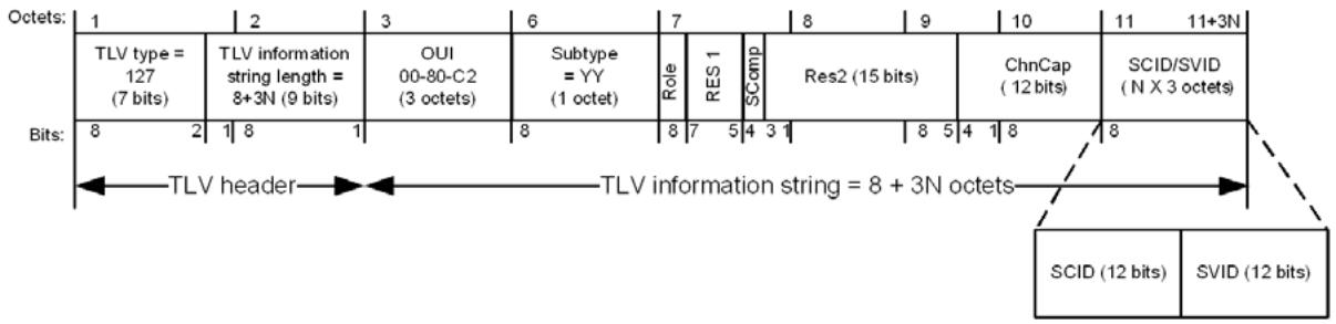
Figure D-14—CDCP TLV structure
D.2.14.1 OUI
The OUI used to identify the CDCP TLV is the 802.1 OUI 00-80-C2.
D.2.14.2 Subtype
The subtype used to identify the CDCP TLV is as shown in Table D-1.
D.2.14.3 Role
Role is a 1-bit field, defined as follows:
a) S(1)—Indicates the sender is operating in the station role, assigns channels numbers and a default SVID for the default channel 1, and requests SVID assignments from the neighboring 'B'.
b) B(0)—Indicates the sender is operating in the Bridge role, accepts S-channel configuration requests from its neighboring 'S' and that the sender will do the best it can to fill the SVID assignment requests from the neighboring 'S'.
D.2.14.4 RES1
RES1 is a 3-bit field, reserved for future standardization. This field is transmitted as zero and ignored on receipt.
D.2.14.5 SComp
SComp is a 1-bit field that indicates the presence or absence of an S-VLAN component for S-channel support. A value of 1 indicates TRUE, zero indicates FALSE.
NOTE—If this bit is zero, then the sender does not have a CDCP state machine, and the other fields in the TLV are not valid.
D.2.14.6 Res2
RES2 is a 15-bit field, reserved for future standardization. This field is transmitted as zero and ignored on receipt.
D.2.14.7 ChnCap
Channel capacity. Identifies the total number of S-channels, both assigned and available to be assigned, that the sender has.
D.2.14.8 SCID/SVID
An SCID/SVID pair exists for each S-channel that is currently supported by the sender. Each SCID/SVID pair consists of two 12-bit values, as follows:
a) SCID—indicates the index number of the S-channel. The station assigns S-channel numbers in the range 0-167. Zero is reserved. The S-channel index should be between 1 and the maximum number of S-channels supported by the port.
b) SVID—The VID assigned to the S-channel. The Bridge assigns SVIDs to channels in the range 1- 0xffe. A station uses the 0 SVID to request an SVID assignment from the Bridge.
After the station receives the SVID assignment from the Bridge, it uses the SVID assigned value in all subsequent exchanges for that specific SCID (SCID/SVID pair).
NOTE 1—The first entry in the list of SCID/SVID pairs contains the default S-channel. (i.e., the first channel pair is <1,1>).
NOTE 2—A maximum of 167 S-channels can be supported. Other formats (assuming sequential SVIDs) could be defined to allow support for 4K+ S-channels.
NOTE 3—This listing can be sparse (in order to indicate arrival and removal of S-channels). The S-channel going away is indicated by removing the SCID/SVID pair.
NOTE 4—The order of the list determines the priority of SVID assignments. If the Bridge does not have resources for all channels, it assigns the first channels in the list.
D.3 IEEE 802.1 Organizationally Specific TLV management
D.3.1 IEEE 802.1 Organizationally Specific TLV selection management
TLV selection management consists of providing the network manager with the means to select which specific IEEE 802.1 Organizationally Specific TLVs are enabled for inclusion in an LLDPDU. The following LLDP variables cross reference to LLDP local systems configuration MIB tables indicate which specific TLVs are enabled for the particular port(s) on the system. The specific port(s) through which each TLV is enabled for transmission may be set (or reset) by the network manager:
a) mibXdot1PortVlanTxEnable: This variable lists the VID of the port through which the referenced TLV is enabled for transmission.
b) mibXdot1VlanNameConfigTxEnable: This variable lists the different VLAN name/PPVID TLVs that are defined for the system, each with a bit map indicating the system ports through which the particular VLAN name TLV is enabled for transmission.
c) mibXdot1ProtoVlanConfigTxEnable: This variable lists the Port And Protocol VLAN TLVs that are defined for the system, each with a bit map indicating the system ports through which the particular Port And Protocol VLAN TLV is enabled for transmission.
d) mibXdot1ProtocolConfigTxEnable: This variable lists the protocol identity TLVs that are defined for the system, each with a bit map indicating the system ports through which the particular protocol TLV is enabled for transmission.
D.3.2 IEEE 802.1 managed objects—TLV variables
D.3.2.1 Port VLAN ID TLV managed objects
a) PVID: The port VLAN identifier (see D.2.1.1).
D.3.2.2 Port And Protocol VLAN ID TLV managed objects
a) Port and protocol VLAN supported: A flag indicating whether port and protocol VLANs are supported (see D.2.2.1).
b) Port and protocol VLAN enabled: A flag indicating whether port and protocol VLANs are enabled (see D.2.2.1).
c) PPVID: The advertised port and protocol VLAN identifier (see D.2.2.2).
D.3.2.3 VLAN Name TLV managed objects
a) VID: The VLAN identifier associated with the VLAN name (see D.2.3.2).
b) VLAN name length: The length of the VLAN name (see D.2.3.3).
c) VLAN name: The VLAN’s name (see D.2.3.4).
D.3.2.4 Protocol Identity TLV managed objects
a) protocol identity length: The length of the protocol identity (see D.2.4.2).
b) protocol identity: The protocol’s identity (see D.2.4.3).
D.3.2.5 VID Usage Digest TLV managed objects
a) VID Usage Digest: The VID Usage Digest value (see D.2.5.1)
D.3.2.6 Management VID TLV managed objects
a) Management VID: The Management VID value (see D.2.6.1)
D.3.2.7 Link Aggregation TLV managed objects
a) aggregation status: The capability and current aggregation status of the link (see D.2.7.1).
b) aggregated port ID: The aggregated port identifier (see D.2.7.2).
D.3.2.8 Congestion Notification TLV managed objects
a) CNPV indicators: A per-priority CNPV indicator vector (see D.2.8.3).
b) CN ready indicators: A per-priority ready indicator vector (see D.2.8.4).
D.3.2.9 EVB TLV managed objects
a) EVB TLV: see D.2.13.
D.3.2.10 CDCP TLV managed objects
a) CDCP TLV: see D.2.14.
D.4 PICS proforma for IEEE 802.1 Organizationally Specific TLV extensions44, 45
D.4.1 Implementation identification
<table><tr><td>Supplier</td><td></td></tr><tr><td>Contact point for queries about the PICS</td><td></td></tr><tr><td>Implementation Name(s) and Version(s)</td><td></td></tr><tr><td>Other information necessary for full identification—e.g., name(s) and version(s) of machines and/or operating system names</td><td></td></tr><tr><td colspan="2">NOTE 1—Only the first three items are required for all implementations; other information may be completed as appropriate in meeting the requirement for full identification.NOTE 2—The terms Name and Version should be interpreted appropriately to correspond with a supplier's terminology (e.g., Type, Series, Model).</td></tr></table>
D.4.2 Protocol summary, IEEE Std 802.1Q
<table><tr><td>Identification of protocol specification</td><td colspan="3">IEEE Std 802.1Q-2014, IEEE Standards for Local and metropolitan area networks—Bridges and Bridged Networks</td></tr><tr><td rowspan="2">Identification of amendments and corrigenda to the PICS proforma that have been completed as part of the PICS</td><td colspan="3">Amd. : Corr. :</td></tr><tr><td colspan="3">Amd. : Corr. :</td></tr><tr><td>Have any Exception items been required?(See A.3.3: The answer Yes means that the implementation does not conform to IEEE Std 802.1Q.)</td><td colspan="2">No [ ]</td><td>Yes [ ]</td></tr></table>
<table><tr><td>Date of Statement</td><td></td></tr></table>
D.4.3 Major capabilities and options
<table><tr><td>Item</td><td>Feature</td><td>Status</td><td>References</td><td>Support</td></tr><tr><td>dot1basicSet</td><td>Is the IEEE 802.1 Organizationally Specific TLV basicSet implemented?</td><td>O.1</td><td>D.1, Table D-1</td><td>Yes [ ] No [ ]</td></tr><tr><td rowspan="8">dot1basictlv</td><td>Is each TLV in the IEEE 802.1 Organizationally Specific TLV basicSet implemented?</td><td></td><td></td><td></td></tr><tr><td>Port VLAN ID TLV</td><td>dot1basicSet:M</td><td>D.2.1</td><td>Yes [ ]</td></tr><tr><td>Port And Protocol VLAN ID TLV</td><td>dot1basicSet:M</td><td>D.2.2</td><td>Yes [ ]</td></tr><tr><td>VLAN Name TLV</td><td>dot1basicSet:M</td><td>D.2.3</td><td>Yes [ ]</td></tr><tr><td>Protocol Identity TLV</td><td>dot1basicSet:M</td><td>D.2.4</td><td>Yes [ ]</td></tr><tr><td>VID Usage Digest TLV</td><td>dot1basicSet:M</td><td>D.2.5</td><td>Yes [ ]</td></tr><tr><td>Management VID TLV</td><td>dot1basicSet:M</td><td>D.2.6</td><td>Yes [ ]</td></tr><tr><td>Link Aggregation TLV</td><td>dot1basicSet:M</td><td>D.2.7</td><td>Yes [ ]</td></tr><tr><td>dot1cnSet</td><td>Is the IEEE 802.1 Organizationally Specific TLV cnSet implemented?</td><td>O.1</td><td>D.1, Table D-1</td><td>Yes [ ] No [ ]</td></tr><tr><td rowspan="2">dot1cntlv</td><td>Is each TLV in the IEEE 802.1 Organizationally Specific TLV lagSet implemented?</td><td></td><td></td><td></td></tr><tr><td>Link Aggregation TLV</td><td>dot1cnSet:M</td><td>D.2.7</td><td>Yes [ ]</td></tr><tr><td>dot1evbSet</td><td>Is the IEEE 802.1 Organizationally Specific TLV evbSet implemented?</td><td>O.1</td><td>D.2.13, D.2.14, Table D-1</td><td>Yes [ ] No [ ]</td></tr><tr><td>dot1evbTlv</td><td>Is each TLV in the IEEE 802.1 Organizationally Specific TLV evbSet implemented?</td><td>dot1evbSet:M</td><td>D.2.13, D.2.14, Table D-1</td><td>Yes [ ] N/A[ ]</td></tr><tr><td rowspan="3">lldpmib</td><td>Which type of MIB is implemented (one is mandatory)?</td><td></td><td></td><td></td></tr><tr><td>SNMP is supported (if yes, answer item snmpmib and skip equivstor)</td><td>O.2</td><td>D.5</td><td>Yes [ ] No [ ]</td></tr><tr><td>SNMP is not supported (if yes, answer equivstor and skip snmpmib)</td><td>O.2</td><td>D.5</td><td>Yes [ ] No [ ]</td></tr><tr><td>snmpmib</td><td>If the SNMP MIB is implemented, is the MIB module in conformance with the MIB sections indicated in Table D-12 for the operating mode being implemented?</td><td>M</td><td>D.5</td><td>Yes [ ]</td></tr><tr><td>equivstor</td><td>If the SNMP is not supported, is the provided storage and retrieval capability functionally equivalent with the indicated specifications of this clause for the operating mode being implemented?</td><td>M</td><td>D.2.1, D.2.2, D.2.3, D.2.4, and D.2.7</td><td>Yes [ ]</td></tr><tr><td>dcbxSet</td><td>Is the IEEE 802.1 DCBX TLV set implemented?</td><td>O.1</td><td>Annex D</td><td>Yes [ ] No [ ]</td></tr><tr><td>dcbxtlv</td><td>Is each TLV in the IEEE 802.1 DCBX TLV set implemented?ETS Configuration TLVETS Recommendation TLVPriority-based Flow ControlConfiguration TLVApplication Priority TLV</td><td>dcbxSet:MdcbxSet:MdcbxSet:MdcbxSet:M</td><td>D.2.9D.2.10D.2.11D.2.12</td><td>Yes [ ]Yes [ ]Yes [ ]Yes [ ]</td></tr></table>
D.5 IEEE 802.1/LLDP extension MIB
D.5.1 Internet Standard Management Framework
LLDP MIBs are designed to operate in a manner consistent with the principles of the Internet Standard Management Framework, which describes the separation of a data modeling language (for example, SMIv2) from content-specific data models (for example, the LLDP remote systems MIB), and from messages and protocol operations used to manipulate the data (for example, SNMPv3).
For a detailed overview of the documents that describe the current Internet Standard Management Framework, refer to section 7 of IETF RFC 3410 (2002).
Managed objects are accessed via a virtual information store, termed the Management Information Base or MIB. MIB objects are generally accessed through the Simple Network Management Protocol (SNMP). Objects in the MIB are defined using the mechanisms defined in the Structure of Management Information (SMI). This clause specifies a MIB module that is compliant to the SMIv2, which is described in IETF STD 58, IETF RFC 2578, IETF RFC 2579, and IETF RFC 2580.
D.5.2 Structure of the IEEE 802.1/LLDP extension MIB
Table D-12 summarizes the particular object groups that are required for each operating mode. The implemented MIB shall comply with the MIB conformance section for the particular operating mode being supported.
Table D-12—IEEE 802.1 extension MIB object group conformance requirements
<table><tr><td>MIB group</td><td>Rx mode</td><td>Tx mode</td><td>Tx/Rx mode</td></tr><tr><td>lldpV2Xdot1ConfigGroup</td><td><eq>M^a</eq></td><td>M</td><td>M</td></tr><tr><td>lldpV2Xdot1LocSysGroup</td><td>M</td><td>—</td><td>M</td></tr><tr><td>lldpV2Xdot1RemSysGroup</td><td>—</td><td>M</td><td>M</td></tr><tr><td>ifGeneralInformationGroup</td><td>M</td><td>M</td><td>M</td></tr><tr><td>lldpXdot1dcbxETSGroup</td><td>DCBX:M</td><td>DCBX:M</td><td>DCBX:M</td></tr><tr><td>lldpXdot1dcbxPFCGroup</td><td>DCBX:M</td><td>DCBX:M</td><td>DCBX:M</td></tr><tr><td>lldpXdot1dcbxApplicationPriorityGroup</td><td>DCBX:M</td><td>DCBX:M</td><td>DCBX:M</td></tr></table>
a M=Mandatory.
Table D-13 shows the structure of the MIB and the relationship of the MIB objects to the LLDP operational status/control variables, LLDP statistics variables, and TLV variables.
Table D-13—IEEE 802.1/LLDP extension MIB object cross reference
<table><tr><td>MIB table</td><td>MIB object</td><td>LLDP reference</td></tr><tr><td colspan="2">Configuration group</td><td></td></tr><tr><td colspan="2">lldpV2Xdot1ConfigPortVlanTable</td><td>AugmentslldpV2Xdot1ConfigPortVlanTable</td></tr><tr><td></td><td>lldpV2Xdot1ConfigPortVlanTxEnable</td><td>Normal LLPDUs, 9.1.2.1 of IEEE Std 802.1AB-2009</td></tr><tr><td colspan="2">lldpV2Xdot1ConfigVlanNameTable</td><td>AugmentslldpV2Xdot1LocVlanNameEntry</td></tr><tr><td></td><td>lldpV2Xdot1ConfigVlanNameTxEnable</td><td>Normal LLPDUs, 9.1.2.1 of IEEE Std 802.1AB-2009</td></tr><tr><td colspan="2">lldpV2Xdot1ConfigProtoVlanTable</td><td>AugmentslldpV2Xdot1LocProtoVlanEntry</td></tr><tr><td></td><td>lldpV2Xdot1ConfigProtoVlanTxEnable</td><td>Normal LLPDUs, 9.1.2.1 of IEEE Std 802.1AB-2009</td></tr><tr><td colspan="2">lldpV2Xdot1ConfigProtocolTable</td><td>AugmentslldpV2Xdot1LocProtocolEntry</td></tr><tr><td></td><td>lldpV2Xdot1ConfigProtocolTxEnable</td><td>Normal LLPDUs, 9.1.2.1 of IEEE Std 802.1AB-2009</td></tr><tr><td colspan="2">lldpV2Xdot1ConfigVidUsageDigestTable</td><td>AugmentslldpV2Xdot1LocVidUsageDigestEntry</td></tr><tr><td></td><td>lldpV2Xdot1ConfigVidUsageDigestTxEnable</td><td>Normal LLPDUs, 9.1.2.1 of IEEE Std 802.1AB-2009</td></tr><tr><td colspan="2">lldpV2Xdot1ConfigManVidTable</td><td>AugmentslldpV2Xdot1LocManVidEntry</td></tr><tr><td></td><td>lldpV2Xdot1ConfigManVidTxEnable</td><td>Normal LLPDUs, 9.1.2.1 of IEEE Std 802.1AB-2009</td></tr><tr><td colspan="2">lldpXdot1CnConfigCnTable</td><td>AugmentslldpV2Xdot1LocManVidEntry</td></tr><tr><td></td><td>lldpXdot1CnConfigCnTxEnable</td><td>Normal LLPDUs, 9.1.2.1 of IEEE Std 802.1AB-2009</td></tr><tr><td colspan="2">lldpXdot1EvbConfigEvbTable</td><td>AugmentslldpV2Xdot1LocManVidEntry</td></tr><tr><td></td><td>lldpXdot1EvbConfigEvbTxEnable</td><td>Normal LLPDUs, 9.1.2.1 of IEEE Std 802.1AB-2009</td></tr><tr><td colspan="2">lldpXdot1EvbConfigCdcpTable</td><td>AugmentslldpV2Xdot1LocManVidEntry</td></tr><tr><td></td><td>lldpXdot1EvbConfigCdcpTxEnable</td><td>Normal LLPDUs, 9.1.2.1 of IEEE Std 802.1AB-2009</td></tr><tr><td colspan="2">Local system information</td><td></td></tr><tr><td colspan="2">lldpV2Xdot1LocTable</td><td>D.2.1</td></tr><tr><td rowspan="2"></td><td>lldpV2LocPortIfIndex</td><td>(Table index)</td></tr><tr><td>lldpV2Xdot1LocPortVlanId</td><td>PVID, D.2.1.1</td></tr><tr><td colspan="2">lldpV2Xdot1LocProtoVlanTable</td><td>D.2.2</td></tr><tr><td rowspan="4"></td><td>lldpV2LocPortIfIndex</td><td>(Table index)</td></tr><tr><td>lldpV2Xdot1LocProtoVlanId</td><td>PPVID, D.2.2.2</td></tr><tr><td>lldpV2Xdot1LocProtoVlanSupported</td><td>flags, D.2.2.1</td></tr><tr><td>lldpV2Xdot1LocProtoVlanEnabled</td><td>flags, D.2.2.1</td></tr><tr><td colspan="2">lldpV2Xdot1LocVlanNameTable</td><td>D.2.3</td></tr><tr><td rowspan="3"></td><td>lldpV2LocPortIfIndex</td><td>(Table index)</td></tr><tr><td>lldpV2Xdot1LocVlanId</td><td>VID, D.2.3.2 (Table index)</td></tr><tr><td>lldpV2Xdot1LocVlanName</td><td>VLAN name, D.2.3.4</td></tr><tr><td colspan="2">lldpV2Xdot1LocProtocolTable</td><td>D.2.4</td></tr><tr><td rowspan="3"></td><td>lldpV2LocPortIfIndex</td><td>(Table index)</td></tr><tr><td>lldpV2Xdot1LocProtocolIndex</td><td>(Table index)</td></tr><tr><td>lldpV2Xdot1LocProtocolId</td><td>protocol identity, D.2.4.3</td></tr><tr><td colspan="2">lldpV2Xdot1LocVidUsageDigestTable</td><td>D.2.5</td></tr><tr><td rowspan="2"></td><td>lldpV2LocPortIfIndex</td><td>(Table index)</td></tr><tr><td>lldpV2Xdot1LocVidUsageDigest</td><td>VID usage digest, D.2.5.1</td></tr><tr><td colspan="2">lldpV2Xdot1LocManVidTable</td><td>D.2.6</td></tr><tr><td rowspan="2"></td><td>lldpV2LocPortIfIndex</td><td>(Table index)</td></tr><tr><td>lldpV2Xdot1LocManVid</td><td>Management VID, D.2.6.1</td></tr><tr><td colspan="2">lldpV2Xdot1LocLinkAggTable</td><td>D.2.7</td></tr><tr><td rowspan="3"></td><td>lldpV2LocPortIfIndex</td><td>(Table index)</td></tr><tr><td>lldpV2Xdot1LocLinkAggStatus</td><td>aggregation status, D.2.7.1</td></tr><tr><td>lldpV2Xdot1LocLinkAggPortId</td><td>aggregated port ID, D.2.7.2</td></tr><tr><td colspan="2">lldpV2Xdot1LocCnTable</td><td>D.2.8</td></tr><tr><td rowspan="3"></td><td>lldpV2LocPortIfIndex</td><td>(Table index)</td></tr><tr><td>lldpV2Xdot1LocCNPVIndicators</td><td>CPNV indicators, D.2.8.3</td></tr><tr><td>lldpV2Xdot1LocReadyIndicators</td><td>Ready indicators, D.2.8.4</td></tr><tr><td colspan="2">lldpV2Xdot1LocEvbTlvTable</td><td>D.2.13</td></tr><tr><td></td><td>lldpV2LocPortIfIndex</td><td>(Table index)</td></tr><tr><td></td><td>lldpV2Xdot1LocEvbTlvString</td><td>EVB TLV string, D.2.13</td></tr><tr><td colspan="2">lldpV2Xdot1LocCDCPTlvTable</td><td>D.2.14</td></tr><tr><td></td><td>lldpV2LocPortIfIndex</td><td>(Table index)</td></tr><tr><td></td><td>lldpV2Xdot1LocCDCPTlvString</td><td>CDCP TLV string, D.2.14</td></tr><tr><td colspan="2">Remote system information</td><td></td></tr><tr><td colspan="2">lldpV2Xdot1RemTable</td><td>D.2.1</td></tr><tr><td rowspan="5"></td><td>lldpV2RemTimeMark</td><td>(Table index)</td></tr><tr><td>lldpV2RemLocalIfIndex</td><td>(Table index)</td></tr><tr><td>lldpV2RemLocalDestMACAddress</td><td>(Table index)</td></tr><tr><td>lldpV2RemIndex</td><td>(Table index)</td></tr><tr><td>lldpV2Xdot1RemPortVlanId</td><td>PVID, D.2.1.1</td></tr><tr><td colspan="2">lldpV2Xdot1RemProtoVlanTable</td><td>D.2.2</td></tr><tr><td rowspan="7"></td><td>lldpV2RemTimeMark</td><td>(Table index)</td></tr><tr><td>lldpV2RemLocalIfIndex</td><td>(Table index)</td></tr><tr><td>lldpV2RemLocalDestMACAddress</td><td>(Table index)</td></tr><tr><td>lldpV2RemIndex</td><td>(Table index)</td></tr><tr><td>lldpV2Xdot1RemProtoVlanId</td><td>PPVID, D.2.2.2 (Table index)</td></tr><tr><td>lldpV2Xdot1RemProtoVlanSupported</td><td>flags, D.2.2.1</td></tr><tr><td>lldpV2Xdot1RemProtoVlanEnabled</td><td>flags, D.2.2.1</td></tr><tr><td colspan="2">lldpV2Xdot1RemVlanNameTable</td><td>D.2.3</td></tr><tr><td rowspan="6"></td><td>lldpV2RemTimeMark</td><td>(Table index)</td></tr><tr><td>lldpV2RemLocalIfIndex</td><td>(Table index)</td></tr><tr><td>lldpV2RemLocalDestMACAddress</td><td>(Table index)</td></tr><tr><td>lldpV2RemIndex</td><td>(Table index)</td></tr><tr><td>lldpV2Xdot1RemVlanId</td><td>VID, D.2.3.2 (Table index)</td></tr><tr><td>lldpV2Xdot1RemVlanName</td><td>VLAN name, D.2.3.4</td></tr><tr><td colspan="2">lldpV2Xdot1RemProtocolTable</td><td>D.2.4</td></tr><tr><td rowspan="6"></td><td>lldpV2RemTimeMark</td><td>(Table index)</td></tr><tr><td>lldpV2RemLocalIfIndex</td><td>(Table index)</td></tr><tr><td>lldpV2RemLocalDestMACAddress</td><td>(Table index)</td></tr><tr><td>lldpV2RemIndex</td><td>(Table index)</td></tr><tr><td>lldpV2Xdot1RemProtocolIndex</td><td>(Table index)</td></tr><tr><td>lldpV2Xdot1RemProtocolId</td><td>protocol identity, D.2.4.3</td></tr><tr><td colspan="2">lldpV2Xdot1RemVidUsageDigestV2Table</td><td>D.2.5</td></tr><tr><td rowspan="5"></td><td>lldpV2RemTimeMark</td><td>(Table index)</td></tr><tr><td>lldpV2RemLocalIfIndex</td><td>(Table index)</td></tr><tr><td>lldpV2RemLocalDestMACAddress</td><td>(Table index)</td></tr><tr><td>lldpV2Xdot1RemIndex</td><td>(Table index)</td></tr><tr><td>lldpV2Xdot1RemVidUsageDigestV2</td><td>VID usage digest, D.2.5.1</td></tr><tr><td colspan="2">lldpV2Xdot1RemManVidV2Table</td><td>D.2.6</td></tr><tr><td rowspan="5"></td><td>lldpV2RemTimeMark</td><td>(Table index)</td></tr><tr><td>lldpV2RemLocalIfIndex</td><td>(Table index)</td></tr><tr><td>lldpV2RemLocalDestMACAddress</td><td>(Table index)</td></tr><tr><td>lldpV2Xdot1RemIndex</td><td>(Table index)</td></tr><tr><td>lldpV2Xdot1RemManVidV2</td><td>Management VID, D.2.6.1</td></tr><tr><td colspan="2">lldpV2Xdot1RemLinkAggTable</td><td>D.2.7</td></tr><tr><td rowspan="6"></td><td>lldpV2RemTimeMark</td><td>(Table index)</td></tr><tr><td>lldpV2RemLocalIfIndex</td><td>(Table index)</td></tr><tr><td>lldpV2RemLocalDestMACAddress</td><td>(Table index)</td></tr><tr><td>lldpV2RemIndex</td><td>(Table index)</td></tr><tr><td>lldpV2Xdot1RemLinkAggStatus</td><td>aggregation status, D.2.7.1</td></tr><tr><td>lldpV2Xdot1RemLinkAggPortId</td><td>aggregation port ID, D.2.7.2</td></tr><tr><td colspan="2">lldpV2Xdot1RemCnTable</td><td>D.2.8</td></tr><tr><td rowspan="6"></td><td>lldpV2RemTimeMark</td><td>(Table index)</td></tr><tr><td>lldpV2RemLocalIfIndex</td><td>(Table index)</td></tr><tr><td>lldpV2RemLocalDestMACAddress</td><td>(Table index)</td></tr><tr><td>lldpV2LocPortIfIndex</td><td>(Table index)</td></tr><tr><td>lldpV2Xdot1RemCNPVIndicators</td><td>CPNV indicators, D.2.8.3</td></tr><tr><td>lldpV2Xdot1RemReadyIndicators</td><td>Ready indicators, D.2.8.4</td></tr><tr><td colspan="2">lldpV2Xdot1RemEvbTlvTable</td><td>D.2.13</td></tr><tr><td></td><td>lldpV2RemTimeMark</td><td>(Table index)</td></tr><tr><td></td><td>lldpV2RemLocalIfIndex</td><td>(Table index)</td></tr><tr><td></td><td>lldpV2RemLocalDestMACAddress</td><td>(Table index)</td></tr><tr><td></td><td>lldpV2RemIndex</td><td>(Table index)</td></tr><tr><td></td><td>lldpV2Xdot1RemEvbTlvString</td><td>EVB TLV string, D.2.13</td></tr><tr><td colspan="2">lldpV2Xdot1RemCDCPTlvTable</td><td>D.2.14</td></tr><tr><td></td><td>lldpV2RemTimeMark</td><td>(Table index)</td></tr><tr><td></td><td>lldpV2RemLocalIfIndex</td><td>(Table index)</td></tr><tr><td></td><td>lldpV2RemLocalDestMACAddress</td><td>(Table index)</td></tr><tr><td></td><td>lldpV2RemIndex</td><td>(Table index)</td></tr><tr><td></td><td>lldpV2Xdot1RemCDCPTlvString</td><td>CDCP TLV string, D.2.14</td></tr><tr><td colspan="3">lldpXdot1dcbxConfig extension group<eq>^a</eq></td></tr><tr><td colspan="2">lldpXdot1dcbxConfigETSConfigurationEntry</td><td></td></tr><tr><td></td><td>lldpXdot1dcbxConfigETSConfigurationTxEnable</td><td>D.2.9</td></tr><tr><td colspan="2">lldpXdot1dcbxConfigETSRecommendationTable</td><td></td></tr><tr><td></td><td>lldpXdot1dcbxConfigETSRecommendationTxEnable</td><td>D.2.10</td></tr><tr><td colspan="2">lldpXdot1dcbxConfigPFCTable</td><td></td></tr><tr><td></td><td>lldpXdot1dcbxConfigPFCTxEnable</td><td>D.2.11</td></tr><tr><td colspan="2">lldpXdot1dcbxConfigApplicationPriorityTable</td><td></td></tr><tr><td></td><td>lldpXdot1dcbxConfigApplicationPriorityTxEnable</td><td>D.2.12</td></tr><tr><td colspan="3">lldpXdot1dcbxLocalData extension group<eq>^a</eq></td></tr><tr><td colspan="2">lldpXdot1dcbxLocETSBasicConfigurationTable</td><td></td></tr><tr><td rowspan="5"></td><td>lldpXdot1dcbxLocETSConCreditBasedShaperSupport</td><td>D.2.9.4</td></tr><tr><td>lldpXdot1dcbxLocETSConMaxTC</td><td>D.2.9.5</td></tr><tr><td>lldpXdot1dcbxLocETSConWilling</td><td>D.2.9.3</td></tr><tr><td>lldpXdot1dcbxLocETSConTrafficClassBandwidthTable</td><td>D.2.9.7</td></tr><tr><td>lldpXdot1dcbxLocETSConTrafficSelectionAlgorithmTable</td><td>D.2.9.8</td></tr><tr><td colspan="2">lldpXdot1dcbxLocETSConPriorityAssignmentTable</td><td></td></tr><tr><td rowspan="2"></td><td>lldpXdot1dcbxLocETSConPriority</td><td>D.2.9.6</td></tr><tr><td>lldpXdot1dcbxLocETSConTrafficClass</td><td>D.2.9.6</td></tr><tr><td colspan="2">lldpXdot1dcbxLocETSRecommendationTable</td><td></td></tr><tr><td></td><td>lldpXdot1dcbxLocETSRecoTrafficClassBandwidthTable</td><td>D.2.10.4</td></tr><tr><td colspan="2">lldpXdot1dcbxLocETSRecoTrafficSelectionAlgorithmTable</td><td></td></tr><tr><td rowspan="2"></td><td>lldpXdot1dcbxLocETSRecoTSAPriority</td><td>D.2.10.5</td></tr><tr><td>lldpXdot1dcbxLocETSRecoTrafficSelectionAlgorithm</td><td>D.2.10.5</td></tr><tr><td colspan="2">lldpXdot1dcbxLocPFCBasicTable</td><td></td></tr><tr><td rowspan="3"></td><td>lldpXdot1dcbxLocPFCWilling</td><td>D.2.11.3</td></tr><tr><td>lldpXdot1dcbxLocPFCMBC</td><td>D.2.11.4</td></tr><tr><td>lldpXdot1dcbxLocPFCCap</td><td>D.2.11.5</td></tr><tr><td colspan="2">lldpXdot1dcbxLocPFCEnableTable</td><td></td></tr><tr><td rowspan="2"></td><td>lldpXdot1dcbxLocPFCEnablePriority</td><td>D.2.11.6</td></tr><tr><td>lldpXdot1dcbxLocPFCEnableEnabled</td><td>D.2.11.6</td></tr><tr><td colspan="2">lldpXdot1dcbxLocApplicationPriorityAppTable</td><td></td></tr><tr><td rowspan="3"></td><td>lldpXdot1dcbxLocApplicationPriorityAESelector</td><td>D.2.12.3</td></tr><tr><td>lldpXdot1dcbxLocApplicationPriorityAEProtocol</td><td>D.2.12.3</td></tr><tr><td>lldpXdot1dcbxLocApplicationPriorityAEPriority</td><td>D.2.12.3</td></tr><tr><td colspan="3">lldpXdot1dcbxRemoteData extension <eq>group^a</eq></td></tr><tr><td colspan="2">lldpXdot1dcbxRemETSBasicConfigurationTable</td><td></td></tr><tr><td rowspan="5"></td><td>lldpXdot1dcbxRemETSConCreditBasedShaperSupport</td><td>D.2.9.4</td></tr><tr><td>lldpXdot1dcbxRemETSConMaxTC</td><td>D.2.9.5</td></tr><tr><td>lldpXdot1dcbxRemETSConWilling</td><td>D.2.9.3</td></tr><tr><td>lldpXdot1dcbxRemETSConTrafficClassBandwidthTable</td><td>D.2.9.7</td></tr><tr><td>lldpXdot1dcbxRemETSConTrafficSelectionAlgorithmTable</td><td>D.2.9.8</td></tr><tr><td colspan="2">lldpXdot1dcbxRemETSConPriorityAssignmentTable</td><td></td></tr><tr><td rowspan="2"></td><td>lldpXdot1dcbxRemETSConPriority</td><td>D.2.9.6</td></tr><tr><td>lldpXdot1dcbxRemETSConTrafficClass</td><td>D.2.9.6</td></tr><tr><td colspan="2">lldpXdot1dcbxRemETSRecommendationTable</td><td></td></tr><tr><td></td><td>lldpXdot1dcbxRemETSRecoTrafficClassBandwidthTable</td><td>D.2.10.4</td></tr><tr><td colspan="2">lldpXdot1dcbxRemETSRecoTrafficSelectionAlgorithmTable</td><td></td></tr><tr><td rowspan="2"></td><td>lldpXdot1dcbxRemETSRecoTSAPriority</td><td>D.2.10.5</td></tr><tr><td>lldpXdot1dcbxRemETSRecoTrafficSelectionAlgorithm</td><td>D.2.10.5</td></tr><tr><td colspan="2">lldpXdot1dcbxRemPFCBasicTable</td><td></td></tr><tr><td rowspan="3"></td><td>lldpXdot1dcbxRemPFCWilling</td><td>D.2.11.3</td></tr><tr><td>lldpXdot1dcbxRemPFCMBC</td><td>D.2.11.4</td></tr><tr><td>lldpXdot1dcbxRemPFCCap</td><td>D.2.11.5</td></tr><tr><td colspan="2">lldpXdot1dcbxRemPFCEnableTable</td><td></td></tr><tr><td rowspan="2"></td><td>lldpXdot1dcbxRemPFCEnablePriority</td><td>D.2.11.6</td></tr><tr><td>lldpXdot1dcbxRemPFCEnableEnabled</td><td>D.2.11.6</td></tr><tr><td colspan="2">lldpXdot1dcbxRemApplicationPriorityAppTable</td><td></td></tr><tr><td rowspan="3"></td><td>lldpXdot1dcbxRemApplicationPriorityAESelector</td><td>D.2.12.3</td></tr><tr><td>lldpXdot1dcbxRemApplicationPriorityAEProtocol</td><td>D.2.12.3</td></tr><tr><td>lldpXdot1dcbxRemApplicationPriorityAEPriority</td><td>D.2.12.3</td></tr><tr><td colspan="3">lldpXdot1dcbxAdminData extension group<eq>^a</eq></td></tr><tr><td colspan="2">lldpXdot1dcbxAdminETSBasicConfigurationTable</td><td></td></tr><tr><td rowspan="5"></td><td>lldpXdot1dcbxAdminETSConCreditBasedShaperSupport</td><td>D.2.9.4</td></tr><tr><td>lldpXdot1dcbxAdminETSConMaxTC</td><td>D.2.9.5</td></tr><tr><td>lldpXdot1dcbxAdminETSConWilling</td><td>D.2.9.3</td></tr><tr><td>lldpXdot1dcbxAdminETSConTrafficClassBandwidthTable</td><td>D.2.9.7</td></tr><tr><td>lldpXdot1dcbxAdminETSConTrafficSelectionAlgorithmTable</td><td>D.2.9.8</td></tr><tr><td colspan="2">lldpXdot1dcbxAdminETSConPriorityAssignmentTable</td><td></td></tr><tr><td rowspan="2"></td><td>lldpXdot1dcbxAdminETSConPriority</td><td>D.2.9.6</td></tr><tr><td>lldpXdot1dcbxAdminETSConTrafficClass</td><td>D.2.9.6</td></tr><tr><td colspan="2">lldpXdot1dcbxAdminETSRecommendationTable</td><td></td></tr><tr><td></td><td>lldpXdot1dcbxAdminETSRecoTrafficClassBandwidthTable</td><td>D.2.10.4</td></tr><tr><td colspan="2">lldpXdot1dcbxAdminETSRecoTrafficSelectionAlgorithmTable</td><td></td></tr><tr><td rowspan="2"></td><td>lldpXdot1dcbxAdminETSRecoTSAPriority</td><td>D.2.10.5</td></tr><tr><td>lldpXdot1dcbxAdminETSRecoTrafficSelectionAlgorithm</td><td>D.2.10.5</td></tr><tr><td colspan="2">lldpXdot1dcbxAdminPFCBasicTable</td><td></td></tr><tr><td rowspan="3"></td><td>lldpXdot1dcbxAdminPFCWilling</td><td>D.2.11.3</td></tr><tr><td>lldpXdot1dcbxAdminPFCMBC</td><td>D.2.11.4</td></tr><tr><td>lldpXdot1dcbxAdminPFCCap</td><td>D.2.11.5</td></tr><tr><td colspan="2">lldpXdot1dcbxAdminPFCEnableTable</td><td></td></tr><tr><td rowspan="2"></td><td>lldpXdot1dcbxAdminPFCEnablePriority</td><td>D.2.11.6</td></tr><tr><td>lldpXdot1dcbxAdminPFCEnableEnabled</td><td>D.2.11.6</td></tr><tr><td colspan="2">lldpXdot1dcbxAdminApplicationPriorityAppTable</td><td></td></tr><tr><td rowspan="3"></td><td>lldpXdot1dcbxAdminApplicationPriorityAESelector</td><td>D.2.12.3</td></tr><tr><td>lldpXdot1dcbxAdminApplicationPriorityAEProtocol</td><td>D.2.12.3</td></tr><tr><td>lldpXdot1dcbxAdminApplicationPriorityAEPriority</td><td>D.2.12.3</td></tr></table>
a The term Extension Group is used here to be consistent with LLDP (see IEEE Std 802.1AB).
D.5.3 Relationship to other MIBs
Version 2 of the IEEE 802.1 LLDP extension MIB module appears in D.5.5. Version 1 of the MIB module that was published in IEEE Std 802.1AB-2005 has been superseded by version 2 of the MIB module, and support of the version 2 module is a requirement for conformance to the required or optional capabilities (Clause 5 of IEEE Std 802.1AB-2009) in IEEE Std 802.1AB-2009. The version 2 MIB module reflects changes in indexation of the MIB objects that support the use of LLDP with multiple destination MAC addresses, as discussed in Clause 6 of IEEE Std 802.1AB-2009.
The relationship of the IEEE 802.1 LLDP extension MIB module to other MIBs, and coexistence between version 1 and version 2 implementations, is further discussed in 11.3 of IEEE Std 802.1AB-2009.
D.5.4 Security considerations for IEEE 802.1 LLDP extension MIB module
There are a number of management objects defined in this MIB module with a MAX-ACCESS clause of read-write46. Such objects may be considered sensitive or vulnerable in some network environments. The support for SET operations in a nonsecure environment without proper protection can have a negative effect on network operations.
Setting the following objects to incorrect values can result in improper operation of LLDP when in the transmit mode:
a) lldpV2Xdot1ConfigPortVlanTxEnableV2
b) lldpV2Xdot1ConfigVlanNameTxEnable
c) lldpV2Xdot1ConfigProtoVlanTxEnable
d) lldpV2Xdot1ConfigProtocolTxEnable
e) lldpV2Xdot1ConfigVidUsageDigestTxEnable
f) lldpV2Xdot1ConfigManVidTxEnable
The following readable objects in this MIB module may be considered to be sensitive or vulnerable in some network environments:
g) MIB objects that are related to the transmit mode
1) lldpV2Xdot1LocPortVlanId
2) lldpV2Xdot1LocProtoVlanSupported
3) lldpV2Xdot1LocProtoVlanEnabled
4) lldpV2Xdot1LocVlanName
5) lldpV2Xdot1LocProtocolId
6) lldpV2Xdot1LocVidUsageDigest
7) lldpV2Xdot1LocManVidTxEnable
8) lldpV2Xdot1LocLinkAggStatus
9) lldpV2Xdot1LocLinkAggPortId
10) lldpXdot1dcbxConfigETSConfigurationEntry
11) lldpXdot1dcbxConfigPFCTable
12) lldpXdot1dcbxLocETSBasicConfigurationTable
13) lldpXdot1dcbxLocETSConPriorityAssignmentTable
14) lldpXdot1dcbxLocETSRecoTrafficSelectionAlgorithmTable
15) lldpXdot1dcbxLocPFCBasicTable
16) lldpXdot1dcbxLocPFCEnableTable
17) lldpXdot1dcbxAdminETSBasicConfigurationTable
18) lldpXdot1dcbxAdminETSConPriorityAssignmentTable
19) lldpXdot1dcbxAdminETSRecoTrafficSelectionAlgorithmTable
20) lldpXdot1dcbxAdminPFCBasicTable
21) lldpXdot1dcbxAdminPFCEnableTable
h) MIB objects that are related to the receive mode
1) lldpV2Xdot1RemPortVlanId
2) lldpV2Xdot1RemProtoVlanSupported
3) lldpV2Xdot1RemProtoVlanEnabled
4) lldpV2Xdot1RemVlanName
5) lldpV2Xdot1RemProtocolId
6) lldpV2Xdot1RemVidUsageDigest
7) lldpV2Xdot1RemManVidTxEnable
8) lldpV2Xdot1RemLinkAggStatus
9) lldpV2Xdot1RemLinkAggPortId
10) lldpXdot1dcbxConfigETSConfigurationEntry
11) lldpXdot1dcbxConfigPFCTable
12) lldpXdot1dcbxRemETSBasicConfigurationTable
13) lldpXdot1dcbxRemETSConPriorityAssignmentTable
14) lldpXdot1dcbxRemETSRecoTrafficSelectionAlgorithmTable
15) lldpXdot1dcbxRemPFCBasicTable
16) lldpXdot1dcbxRemPFCEnableTable
17) lldpXdot1dcbxAdminETSBasicConfigurationTable
18) lldpXdot1dcbxAdminETSConPriorityAssignmentTable
19) lldpXdot1dcbxAdminETSRecoTrafficSelectionAlgorithmTable
20) lldpXdot1dcbxAdminPFCBasicTable
21) lldpXdot1dcbxAdminPFCEnableTable
This concern applies both to objects that describe the configuration of the local host, as well as for objects that describe information from the remote hosts, acquired via LLDP and displayed by the objects in this MIB module. It is thus important to control even GET and/or NOTIFY access to these objects and possibly to even encrypt the values of these objects when sending them over the network via SNMP.
SNMP versions prior to SNMPv3 did not include adequate security. Even if the network itself is secure (for example, by using IPSec), there is no control about who on the secure network is allowed to access and GET/SET (read/change/create/delete) the objects in this MIB module.
Implementers should consider the security features as provided by the SNMPv3 framework (see IETF RFC 3410 (2002), section 8), including full support for the SNMPv3 cryptographic mechanisms (for authentication and privacy).
Further, implementers should not deploy SNMP versions prior to SNMPv3. Instead, implementers should deploy SNMPv3 to enable cryptographic security. It is then a customer/operator responsibility to ensure that the SNMP entity giving access to an instance of this MIB module is properly configured to give access to the objects only to those principals (users) that have legitimate rights to indeed GET or SET (change/create/ delete) them.
D.5.5 IEEE 802.1 LLDP extension MIB module—version 2 47, 48
In the following MIB definition, should any discrepancy between the DESCRIPTION text and the corresponding definition in D.2.1 through D.5 occur, the definition in D.2.1 through D.5 shall take precedence.
LLDP-EXT-DOT1-V2-MIB DEFINITIONS ::= BEGIN
IMPORTS
MODULE-IDENTITY,
OBJECT-TYPE,
Unsigned32
FROM SNMPv2-SMI
TruthValue,
TEXTUAL-CONVENTION
FROM SNMPv2-TC
SnmpAdminString
FROM SNMP-FRAMEWORK-MIB
MODULE-COMPLIANCE,
OBJECT-GROUP
FROM SNMPv2-CONF
ifGeneralInformationGroup
FROM IF-MIB
lldpV2Extensions,
lldpV2LocPortIfIndex,
lldpV2RemTimeMark,
lldpV2RemLocalIfIndex,
lldpV2RemLocalDestMACAddress,
lldpV2RemIndex,
lldpV2PortConfigEntry
FROM LLDP-V2-MIB
VlanId
FROM Q-BRIDGE-MIB
LldpV2LinkAggStatusMap
FROM LLDP-V2-TC-MIB
IEEE8021PriorityValue
FROM IEEE8021-TC-MIB;
lldpV2Xdot1MIB MODULE-IDENTITY
LAST-UPDATED "201412150000Z" -- December 15, 2014
ORGANIZATION "IEEE 802.1 Working Group"
CONTACT-INFO
"WG-URL: http://grouper.ieee.org/groups/802/1/index.html
WG-EMail: STDS-802-1-L@LISTSERV.IEEE.ORG
Contact: IEEE 802.1 Working Group Chair
Postal: C/O IEEE 802.1 Working Group
IEEE Standards Association
445 Hoes Lane
P.O. Box 1331
Piscataway
NJ 08855-1331
USA
E-mail: STDS-802-1-L@LISTSERV.IEEE.ORG" DESCRIPTION "The LLDP Management Information Base extension module for IEEE 802.1 organizationally defined discovery information. In order to ensure the uniqueness of the LLDP-V2-MIB, lldpV2Xdot1MIB is branched from lldpV2Extensions using an Organizationally Unique Identifier (OUI) value as the node. An OUI is a 24 bit globally unique number assigned by the IEEE Registration Authority - see: http://standards.ieee.org/develop/regauth/oui/index.html Unless otherwise indicated, the references in this MIB module are to IEEE Std 802.1Q-2014. Copyright (C) IEEE (2014). This version of this MIB module is published as D.5.5 of IEEE Std 802.1Q; see the standard itself for full legal notices."
REVISION "201412150000Z" -- December 15, 2014
DESCRIPTION
"Published as part of IEEE Std 802.1Q 2014 revision. Cross references updated and corrected. New tables lldpV2Xdot1RemVidUsageDigestV2Table and lldpV2Xdot1RemManVidV2Table inserted; old versions deprecated. New versions add an index for lldpV2RemIndex. "
REVISION "201103250000Z" -- March 25, 2011
DESCRIPTION
"Published as part of IEEE Std 802.1Qaz-2011. Adds the DCBX objects to the MIB module"
REVISION "201103230000Z" -- March 23, 2011
DESCRIPTION
"Published as part of IEEE Std 802.1Q-2011 revision. This revision contains changes associated with relocating the extension MIB from IEEE Std 802.1AB to IEEE Std 802.1Q, minor tweaks to the text of the DESCRIPTION statement above to fix references to IEEE Std 802.1Q, updating of references to refer to Annex D, and addition of object definitions for Congestion Notification TLVs and corresponding compliance statements."
REVISION "200906080000Z" -- June 08, 2009
DESCRIPTION
"Published as part of IEEE Std 802.1AB-2009 revision. This revision incorporated changes to the MIB to support the use of LLDP with multiple destination MAC addresses, and to import the Link Aggregation TLV from the 802.3 extension MIB"
-- OUI for IEEE 802.1 is 32962 (00-80-C2)
::= { lldpV2Extensions 32962 }
-- Organizationally Defined Information Extension - IEEE 802.1
-- Definitions to support the basicSet TLV set (Table D-1)
lldpV2Xdot1Objects OBJECT IDENTIFIER ::= { lldpV2Xdot1MIB 1 }
-- LLDP IEEE 802.1 extension MIB groups
lldpV2Xdot1Config OBJECT IDENTIFIER ::= { lldpV2Xdot1Objects 1 }
lldpV2Xdot1LocalData OBJECT IDENTIFIER ::= { lldpV2Xdot1Objects 2 }
lldpV2Xdot1RemoteData OBJECT IDENTIFIER ::= { lldpV2Xdot1Objects 3 }
-- IEEE 802.1 - Configuration for the basicSet TLV set
--
-- lldpV2Xdot1ConfigPortVlanTable : configure the transmission of the
-- Port VLAN-ID TLVs on set of ports.
lldpV2Xdot1ConfigPortVlanTable OBJECT-TYPE
SYNTAX SEQUENCE OF LldpV2Xdot1ConfigPortVlanEntry
MAX-ACCESS not-accessible
STATUS current
DESCRIPTION
"A table that controls selection of LLDP Port VLAN-ID TLVs
to be transmitted on individual ports."
::= { lldpV2Xdot1Config 1 }
lldpV2Xdot1ConfigPortVlanEntry OBJECT-TYPE
SYNTAX LldpV2Xdot1ConfigPortVlanEntry
MAX-ACCESS not-accessible
STATUS current
DESCRIPTION
"LLDP configuration information that controls the
transmission of IEEE 802.1 organizationally defined Port
VLAN-ID TLV on LLDP transmission capable ports.
This configuration object augments the
lldpV2PortConfigEntry of the LLDP-MIB, therefore it is only
present along with the port configuration defined by the
associated lldpV2PortConfigEntry entry.
Each active lldpConfigEntry is restored from non-volatile
storage (along with the corresponding
lldpV2PortConfigEntry) after a re-initialization of the
management system."
AUGMENTS { lldpV2PortConfigEntry }
::= { lldpV2Xdot1ConfigPortVlanTable 1 }
LldpV2Xdot1ConfigPortVlanEntry ::= SEQUENCE {
lldpV2Xdot1ConfigPortVlanTxEnable TruthValue
}
lldpV2Xdot1ConfigPortVlanTxEnable OBJECT-TYPE
SYNTAX TruthValue
MAX-ACCESS read-write
STATUS current
DESCRIPTION
"The lldpV2Xdot1ConfigPortVlanTxEnable, which is defined as a truth value and configured by the network management, determines whether the IEEE 802.1 organizationally defined port VLAN TLV transmission is allowed on a given LLDP transmission capable port.
The value of this object is restored from non-volatile storage after a re-initialization of the management system."
REFERENCE
"9.1.2.1 of IEEE Std 802.1AB"
DEFVAL { false }
::= { lldpV2Xdot1ConfigPortVlanEntry 1 }
-- lldpV2Xdot1ConfigVlanNameTable : configure the transmission of the
-- VLAN name instances on set of ports.
--
lldpV2Xdot1ConfigVlanNameTable OBJECT-TYPE
SYNTAX SEQUENCE OF LldpV2Xdot1ConfigVlanNameEntry
MAX-ACCESS not-accessible
STATUS current
DESCRIPTION
"The table that controls selection of LLDP VLAN name TLV instances to be transmitted on individual ports."
::= { lldpV2Xdot1Config 2 }
lldpV2Xdot1ConfigVlanNameEntry OBJECT-TYPE
SYNTAX LldpV2Xdot1ConfigVlanNameEntry
MAX-ACCESS not-accessible
STATUS current
DESCRIPTION
"LLDP configuration information that specifies the set of ports (represented as a PortList) on which the Local System VLAN name instance is transmitted.
This configuration object augments the lldpV2LocVlanEntry, therefore it is only present along with the VLAN Name instance contained in the associated lldpV2LocVlanNameEntry entry.
Each active lldpV2Xdot1ConfigVlanNameEntry is restored from non-volatile storage (along with the corresponding lldpV2Xdot1LocVlanNameEntry) after a re-initialization of the management system."
AUGMENTS { lldpV2Xdot1LocVlanNameEntry }
::= { lldpV2Xdot1ConfigVlanNameTable 1 }
LldpV2Xdot1ConfigVlanNameEntry ::= SEQUENCE {
lldpV2Xdot1ConfigVlanNameTxEnable TruthValue
}
lldpV2Xdot1ConfigVlanNameTxEnable OBJECT-TYPE
SYNTAX TruthValue
MAX-ACCESS read-write
STATUS current
DESCRIPTION
"The boolean value that indicates whether the corresponding Local System VLAN name instance is transmitted on the port defined by the given lldpV2Xdot1LocVlanNameEntry.
The value of this object is restored from non-volatile storage after a re-initialization of the management system."
REFERENCE
"9.1.2.1 of IEEE Std 802.1AB"
DEFVAL { false }
::= { lldpV2Xdot1ConfigVlanNameEntry 1 }
--
-- lldpV2Xdot1ConfigProtoVlanTable : configure the transmission of the protocol VLAN instances on set of ports.
--
--
lldpV2Xdot1ConfigProtoVlanTable OBJECT-TYPE
SYNTAX SEQUENCE OF LldpV2Xdot1ConfigProtoVlanEntry
MAX-ACCESS not-accessible
STATUS current
DESCRIPTION
"The table that controls selection of LLDP Port And Protocol VLAN ID TLV instances to be transmitted on individual ports."
::= { lldpV2Xdot1Config 3 }
lldpV2Xdot1ConfigProtoVlanEntry OBJECT-TYPE
SYNTAX LldpV2Xdot1ConfigProtoVlanEntry
MAX-ACCESS not-accessible
STATUS current
DESCRIPTION
"LLDP configuration information that specifies the set of ports (represented as a PortList) on which the Local System Protocol VLAN instance is transmitted.
This configuration object augments the lldpV2Xdot1LocVlanEntry, therefore it is only present along with the Port and Protocol VLAN ID instance contained in the associated lldpV2Xdot1LocVlanEntry.
Each active lldpV2Xdot1ConfigProtoVlanEntry is restored from non-volatile storage (along with the corresponding lldpV2Xdot1LocProtoVlanEntry) after a re-initialization of the management system."
AUGMENTS { lldpV2Xdot1LocProtoVlanEntry }
::= { lldpV2Xdot1ConfigProtoVlanTable 1 }
LldpV2Xdot1ConfigProtoVlanEntry ::= SEQUENCE {
lldpV2Xdot1ConfigProtoVlanTxEnable TruthValue
}
lldpV2Xdot1ConfigProtoVlanTxEnable OBJECT-TYPE
SYNTAX TruthValue
MAX-ACCESS read-write
STATUS current
DESCRIPTION
"The boolean value that indicates whether the corresponding Local System Port and Protocol VLAN instance is transmitted on the port defined by the given lldpV2Xdot1LocProtoVlanEntry.
The value of this object is restored from non-volatile storage after a re-initialization of the management system."
REFERENCE
"9.1.2.1 of IEEE Std 802.1AB"
DEFVAL { false }
::= { lldpV2Xdot1ConfigProtoVlanEntry 1 }
--
-- lldpV2Xdot1ConfigProtocolTable : configure the transmission of the protocol instances on set of ports.
--
--
lldpV2Xdot1ConfigProtocolTable OBJECT-TYPE
SYNTAX SEQUENCE OF LldpV2Xdot1ConfigProtocolEntry
MAX-ACCESS not-accessible
STATUS current
DESCRIPTION
"The table that controls selection of LLDP Protocol TLV instances to be transmitted on individual ports."
::= { lldpV2Xdot1Config 4 }
lldpV2Xdot1ConfigProtocolEntry OBJECT-TYPE
SYNTAX LldpV2Xdot1ConfigProtocolEntry
MAX-ACCESS not-accessible
STATUS current
DESCRIPTION
"LLDP configuration information that specifies the set of ports (represented as a PortList) on which the Local System Protocol instance is transmitted.
This configuration object augments the lldpV2Xdot1LocProtoEntry, therefore it is only present along with the Protocol instance contained in the associated lldpV2Xdot1LocProtoEntry.
Each active lldpV2Xdot1ConfigProtocolEntry is restored from non-volatile storage (along with the corresponding lldpV2Xdot1LocProtocolEntry) after a re-initialization of the management system."
AUGMENTS { lldpV2Xdot1LocProtocolEntry }
::= { lldpV2Xdot1ConfigProtocolTable 1 }
LldpV2Xdot1ConfigProtocolEntry ::= SEQUENCE {
lldpV2Xdot1ConfigProtocolTxEnable TruthValue
}
lldpV2Xdot1ConfigProtocolTxEnable OBJECT-TYPE
SYNTAX TruthValue
MAX-ACCESS read-write
STATUS current
DESCRIPTION
"The boolean value that indicates whether the corresponding Local System Protocol Identity instance is transmitted on the port defined by the given lldpV2Xdot1LocProtocolEntry.
The value of this object is restored from non-volatile storage after a re-initialization of the management system."
REFERENCE
"9.1.2.1 of IEEE Std 802.1AB"
DEFVAL { false }
::= { lldpV2Xdot1ConfigProtocolEntry 1 }
--
-- lldpV2Xdot1ConfigVidUsageDigestTable: configure the transmission
-- of the VID Usage Digest TLVs on set of ports.
--
lldpV2Xdot1ConfigVidUsageDigestTable OBJECT-TYPE
SYNTAX SEQUENCE OF LldpV2Xdot1ConfigVidUsageDigestEntry
MAX-ACCESS not-accessible
STATUS current
DESCRIPTION
"A table that controls selection of LLDP VID Usage Digest TLVs to be transmitted on individual ports."
::= { lldpV2Xdot1Config 5 }
lldpV2Xdot1ConfigVidUsageDigestEntry OBJECT-TYPE
SYNTAX LldpV2Xdot1ConfigVidUsageDigestEntry
MAX-ACCESS not-accessible
STATUS current
DESCRIPTION
"LLDP configuration information that specifies the set of ports (represented as a PortList) on which the local system VID Usage Digest instance will be transmitted.
This configuration object augments the lldpLocVidUsageDigestEntry, therefore it is only present along with the VID Usage Digest instance contained in the associated lldpV2Xdot1LocVidUsageDigestEntry entry. Each active lldpConfigVidUsageDigestEntry must be restored from non-volatile storage and re-created (along with the corresponding lldpV2Xdot1LocVidUsageDigestEntry) after a re-initialization of the management system."
AUGMENTS { lldpV2Xdot1LocVidUsageDigestEntry }
::= { lldpV2Xdot1ConfigVidUsageDigestTable 1 }
LldpV2Xdot1ConfigVidUsageDigestEntry ::= SEQUENCE {
lldpV2Xdot1ConfigVidUsageDigestTxEnable TruthValue
}
lldpV2Xdot1ConfigVidUsageDigestTxEnable OBJECT-TYPE
SYNTAX TruthValue
MAX-ACCESS read-write
STATUS current
DESCRIPTION
"The boolean value that indicates whether the corresponding Local System VID Usage Digest instance will be transmitted on the port defined by the given lldpV2Xdot1LocVidUsageDigestEntry. The value of this object must be restored from non-volatile storage after a reinitialization of the management system."
REFERENCE
"9.1.2.1 of IEEE Std 802.1AB"
DEFVAL { false }
::= { lldpV2Xdot1ConfigVidUsageDigestEntry 1 }
--
-- lldpV2Xdot1ConfigManVidTable : configure the transmission of the -- Management VID TLVs on set of ports.
--
lldpV2Xdot1ConfigManVidTable OBJECT-TYPE
SYNTAX SEQUENCE OF LldpV2Xdot1ConfigManVidEntry
MAX-ACCESS not-accessible
STATUS current
DESCRIPTION
"A table that controls selection of LLDP Management VID TLVs to be transmitted on individual ports."
::= { lldpV2Xdot1Config 6 }
lldpV2Xdot1ConfigManVidEntry OBJECT-TYPE
SYNTAX LldpV2Xdot1ConfigManVidEntry
MAX-ACCESS not-accessible
STATUS current
DESCRIPTION
"LLDP configuration information that specifies the set of port/destination address pairs on which the Local System Management VID will be transmitted.
This configuration object augments the lldpV2Xdot1LocManVidEntry, therefore it is only present along with the Management VID contained in the associated lldpV2Xdot1LocManVidEntry entry.
Each active lldpV2Xdot1ConfigManVidEntry must be restored from non-volatile storage (along with the corresponding lldpV2Xdot1LocManVidEntry) after a re-initialization of the management system."
AUGMENTS { lldpV2Xdot1LocManVidEntry }
::= { lldpV2Xdot1ConfigManVidTable 1 }
LldpV2Xdot1ConfigManVidEntry ::= SEQUENCE {
lldpV2Xdot1ConfigManVidTxEnable TruthValue
}
lldpV2Xdot1ConfigManVidTxEnable OBJECT-TYPE
SYNTAX TruthValue
MAX-ACCESS read-write
STATUS current
DESCRIPTION
"The lldpV2Xdot1ConfigManVidTxEnable, which is defined as a
truth value and configured by the network management,
determines whether the IEEE 802.1 organizationally
defined Management VID TLV transmission is allowed on a given
LLDP transmission capable port.
The value of this object must be restored from
non-volatile storage after a re-initialization of the
management system."
REFERENCE
"9.1.2.1 of IEEE Std 802.1AB"
DEFVAL { false }
::= { lldpV2Xdot1ConfigManVidEntry 1 }
-- IEEE 802.1 - Local System Information
--
-- lldpV2Xdot1LocTable - indexed by ifIndex.
--
lldpV2Xdot1LocTable OBJECT-TYPE
SYNTAX SEQUENCE OF LldpV2Xdot1LocEntry
MAX-ACCESS not-accessible
STATUS current
DESCRIPTION
"This table contains one row per port for IEEE 802.1
organizationally defined LLDP extension on the local system
known to this agent."
::= { lldpV2Xdot1LocalData 1 }
lldpV2Xdot1LocEntry OBJECT-TYPE
SYNTAX LldpV2Xdot1LocEntry
MAX-ACCESS not-accessible
STATUS current
DESCRIPTION
"Information about IEEE 802.1 organizationally defined LLDP extension."
INDEX { lldpV2LocPortIfIndex }
::= { lldpV2Xdot1LocTable 1 }
LldpV2Xdot1LocEntry ::= SEQUENCE {
lldpV2Xdot1LocPortVlanId Unsigned32
}
lldpV2Xdot1LocPortVlanId OBJECT-TYPE
SYNTAX Unsigned32(0|1..4094)
MAX-ACCESS read-only
STATUS current
DESCRIPTION
"The integer value used to identify the port's VLAN identifier associated with the local system. A value of zero shall be used if the system either does not know the PVID or does not support Port-based VLAN operation."
REFERENCE
"D.2.1.1"
::= { lldpV2Xdot1LocEntry 1 }
-- lldpV2Xdot1LocProtoVlanTable: Port and Protocol VLAN information
-- re-indexed by ifIndex.
ldpV2Xdot1LocProtoVlanTable OBJECT-TYPE
SYNTAX SEQUENCE OF LldpV2Xdot1LocProtoVlanEntry
MAX-ACCESS not-accessible
STATUS current
DESCRIPTION
"This table contains one or more rows per Port and Protocol VLAN information about the local system."
::= { lldpV2Xdot1LocalData 2 }
ldpV2Xdot1LocProtoVlanEntry OBJECT-TYPE
SYNTAX LldpV2Xdot1LocProtoVlanEntry
MAX-ACCESS not-accessible
STATUS current
DESCRIPTION
"Port and protocol VLAN ID Information about a particular port component. There may be multiple port and protocol VLANs, identified by a particular lldpV2Xdot1LocProtoVlanId, configured on the given port."
INDEX { lldpV2LocPortIfIndex,
lldpV2Xdot1LocProtoVlanId }
::= { lldpV2Xdot1LocProtoVlanTable 1 }
LldpV2Xdot1LocProtoVlanEntry ::= SEQUENCE {
lldpV2Xdot1LocProtoVlanId Unsigned32,
lldpV2Xdot1LocProtoVlanSupported TruthValue,
lldpV2Xdot1LocProtoVlanEnabled TruthValue
}
ldpV2Xdot1LocProtoVlanId OBJECT-TYPE
SYNTAX Unsigned32(0|1..4094)
MAX-ACCESS not-accessible
STATUS current
DESCRIPTION
"The integer value used to identify the port and protocol VLANs associated with the given port associated with the local system. A value of zero shall be used if the system either does not know the protocol VLAN ID (PPVID) or does not support port and protocol VLAN operation."
REFERENCE
"D.2.2.2"
::= { lldpV2Xdot1LocProtoVlanEntry 1 }
ldpV2Xdot1LocProtoVlanSupported OBJECT-TYPE
SYNTAX TruthValue
MAX-ACCESS read-only
STATUS current
DESCRIPTION
"The truth value used to indicate whether the given port (associated with the local system) supports port and protocol VLANs."
REFERENCE
"D.2.2.1"
::= { lldpV2Xdot1LocProtoVlanEntry 2 }
lldpV2Xdot1LocProtoVlanEnabled OBJECT-TYPE
SYNTAX TruthValue
MAX-ACCESS read-only
STATUS current
DESCRIPTION
"The truth value used to indicate whether the port and protocol VLANs are enabled on the given port associated with the local system."
REFERENCE
"D.2.2.1"
::= { lldpV2Xdot1LocProtoVlanEntry 3 }
--
-- lldpV2Xdot1LocVlanNameTable : VLAN name information about the local
-- system indexed by ifIndex.
--
lldpV2Xdot1LocVlanNameTable OBJECT-TYPE
SYNTAX SEQUENCE OF LldpV2Xdot1LocVlanNameEntry
MAX-ACCESS not-accessible
STATUS current
DESCRIPTION
"This table contains one or more rows per IEEE 802.1Q VLAN name information on the local system known to this agent."
::= { lldpV2Xdot1LocalData 3 }
lldpV2Xdot1LocVlanNameEntry OBJECT-TYPE
SYNTAX LldpV2Xdot1LocVlanNameEntry
MAX-ACCESS not-accessible
STATUS current
DESCRIPTION
"VLAN name Information about a particular port component. There may be multiple VLANs, identified by a particular lldpV2Xdot1LocVlanId, configured on the given port."
INDEX { lldpV2LocPortIfIndex,
lldpV2Xdot1LocVlanId }
::= { lldpV2Xdot1LocVlanNameTable 1 }
LldpV2Xdot1LocVlanNameEntry ::= SEQUENCE {
lldpV2Xdot1LocVlanId VlanId,
lldpV2Xdot1LocVlanName SnmpAdminString
}
lldpV2Xdot1LocVlanId OBJECT-TYPE
SYNTAX VlanId
MAX-ACCESS not-accessible
STATUS current
DESCRIPTION
"The integer value used to identify the IEEE 802.1Q VLAN IDs with which the given port is compatible."
REFERENCE
"D.2.3.2"
::= { lldpV2Xdot1LocVlanNameEntry 1 }
lldpV2Xdot1LocVlanName OBJECT-TYPE
SYNTAX SnmpAdminString (SIZE(1..32))
MAX-ACCESS read-only
STATUS current
DESCRIPTION
"The string value used to identify VLAN name identified by the Vlan Id associated with the given port on the local system.
This object should contain the value of the dot1QVLANStaticName object (defined in IETF RFC 4363) identified with the given lldpV2Xdot1LocVlanId."
REFERENCE
"D.2.3.4"
::= { lldpV2Xdot1LocVlanNameEntry 2 }
--
-- lldpV2Xdot1LocProtocolTable : Protocol Identity information
-- re-indexed by ifIndex and destination address
--
lldpV2Xdot1LocProtocolTable OBJECT-TYPE
SYNTAX SEQUENCE OF LldpV2Xdot1LocProtocolEntry
MAX-ACCESS not-accessible
STATUS current
DESCRIPTION
"This table contains one or more rows per protocol identity information on the local system known to this agent."
REFERENCE
"D.2.4"
::= { lldpV2Xdot1LocalData 4 }
lldpV2Xdot1LocProtocolEntry OBJECT-TYPE
SYNTAX LldpV2Xdot1LocProtocolEntry
MAX-ACCESS not-accessible
STATUS current
DESCRIPTION
"Information about particular protocols that are accessible through the given port component.
There may be multiple protocols, identified by particular lldpV2Xdot1ProtocolIndex, lldpV2LocPortIfIndex"
REFERENCE
"D.2.4"
INDEX { lldpV2LocPortIfIndex,
lldpV2Xdot1LocProtocolIndex }
::= { lldpV2Xdot1LocProtocolTable 1 }
LldpV2Xdot1LocProtocolEntry ::= SEQUENCE {
lldpV2Xdot1LocProtocolIndex Unsigned32,
lldpV2Xdot1LocProtocolId OCTET STRING
}
lldpV2Xdot1LocProtocolIndex OBJECT-TYPE
SYNTAX Unsigned32(1..2147483647)
MAX-ACCESS not-accessible
STATUS current
DESCRIPTION
"This object represents an arbitrary local integer value used by this agent to identify a particular protocol identity."
::= { lldpV2Xdot1LocProtocolEntry 1 }
lldpV2Xdot1LocProtocolId OBJECT-TYPE
SYNTAX OCTET STRING (SIZE (1..255))
MAX-ACCESS read-only
STATUS current
DESCRIPTION
"The octet string value used to identify the protocols associated with the given port of the local system."
REFERENCE
"D.2.4.3"
::= { lldpV2Xdot1LocProtocolEntry 2 }
--
-- lldpV2Xdot1LocVidUsageDigestTable: Table of hash values of
-- system VID Usage Table transmitted
-- via VID Usage Digest TLV.
--
lldpV2Xdot1LocVidUsageDigestTable OBJECT-TYPE
SYNTAX SEQUENCE OF LldpV2Xdot1LocVidUsageDigestEntry
MAX-ACCESS not-accessible
STATUS current
DESCRIPTION
"This table contains one row per ifIndex/
destination MAC address pair for usage digest information on the local system known to this agent."
REFERENCE
"D.2.5"
::= { lldpV2Xdot1LocalData 5 }
lldpV2Xdot1LocVidUsageDigestEntry OBJECT-TYPE
SYNTAX LldpV2Xdot1LocVidUsageDigestEntry
MAX-ACCESS not-accessible
STATUS current
DESCRIPTION
"Usage digest information to be transmitted through the given port."
REFERENCE
"D.2.5"
INDEX { lldpV2LocPortIfIndex }
::= { lldpV2Xdot1LocVidUsageDigestTable 1 }
LldpV2Xdot1LocVidUsageDigestEntry ::= SEQUENCE {
lldpV2Xdot1LocVidUsageDigest Unsigned32
}
lldpV2Xdot1LocVidUsageDigest OBJECT-TYPE
SYNTAX Unsigned32
MAX-ACCESS read-only
STATUS current
DESCRIPTION
"The integer value obtained by applying the CRC32 function
to the 128-octet VID Usage Table. A bit of the VID Usage
Table contains the value PBB-TE-USAGE (binary 1) if the
corresponding element of the MST Configuration Table
(IEEE Std 802.1Q 8.9.1) contains the value PBB-TE MSTID
(hex FFE) and otherwise contains the value NON-PBB-TE-USAGE
(binary 0)."
REFERENCE
"D.2.5.1"
::= { lldpV2Xdot1LocVidUsageDigestEntry 1 }
--
-- lldpV2Xdot1LocManVidTable: Table of values configured on the Local
-- system for the Management VID, or the value 0 if a Management VID
-- has not been provisioned.
--
lldpV2Xdot1LocManVidTable OBJECT-TYPE
SYNTAX SEQUENCE OF LldpV2Xdot1LocManVidEntry
MAX-ACCESS not-accessible
STATUS current
DESCRIPTION
"This table contains one row per ifIndex/
destination MAC address pair for usage digest
information on the local system known to this agent."
REFERENCE
"D.2.6"
::= { lldpV2Xdot1LocalData 6 }
lldpV2Xdot1LocManVidEntry OBJECT-TYPE
SYNTAX LldpV2Xdot1LocManVidEntry
MAX-ACCESS not-accessible
STATUS current
DESCRIPTION
"Usage digest information to be transmitted
through the given port."
REFERENCE
"D.2.6"
INDEX { lldpV2LocPortIfIndex }
::= { lldpV2Xdot1LocManVidTable 1 }
LldpV2Xdot1LocManVidEntry ::= SEQUENCE {
lldpV2Xdot1LocManVid Unsigned32
}
lldpV2Xdot1LocManVid OBJECT-TYPE
SYNTAX Unsigned32 (0|1..4094)
MAX-ACCESS read-only
STATUS current
DESCRIPTION
"The integer value configured on the Local system for
the Management VID, or
the value 0 if a Management VID has not been provisioned."
REFERENCE
"D.2.6.1"
::= { lldpV2Xdot1LocManVidEntry 1 }
-- IEEE 802.1 - Local System Information - Link Aggregation
---
---
---
---
1ldpV2Xdot1LocLinkAggTable: Link Aggregation Information Table
---
---
1ldpV2Xdot1LocLinkAggTable OBJECT-TYPE
SYNTAX SEQUENCE OF LldpV2Xdot1LocLinkAggEntry
MAX-ACCESS not-accessible
STATUS current
DESCRIPTION "This table contains one row per port of link aggregation information (as a part of the LLDP 802.1 organizational extension) on the local system known to this agent." ::= { lldpV2Xdot1LocalData 7 }
1ldpV2Xdot1LocLinkAggEntry OBJECT-TYPE
SYNTAX LldpV2Xdot1LocLinkAggEntry
MAX-ACCESS not-accessible
STATUS current
DESCRIPTION "Link Aggregation information about a particular port component."
INDEX { lldpV2LocPortIfIndex } ::= { lldpV2Xdot1LocLinkAggTable 1 }
1ldpV2Xdot1LocLinkAggEntry ::= SEQUENCE { lldpV2Xdot1LocLinkAggStatus LldpV2LinkAggStatusMap, lldpV2Xdot1LocLinkAggPortId Unsigned32 }
1ldpV2Xdot1LocLinkAggStatus OBJECT-TYPE
SYNTAX LldpV2LinkAggStatusMap
MAX-ACCESS read-only
STATUS current
DESCRIPTION "The bitmap value contains the link aggregation capabilities and the current aggregation status of the link."
REFERENCE "D.2.7.1" ::= { lldpV2Xdot1LocLinkAggEntry 1 }
1ldpV2Xdot1LocLinkAggPortId OBJECT-TYPE
SYNTAX Unsigned32(0|1..2147483647)
MAX-ACCESS read-only
STATUS current
DESCRIPTION "This object contains the IEEE 802.1 aggregated port identifier, aAggPortID (IEEE Std 802.1AX, 6.3.2.1.1), derived from the ifNumber of the ifIndex for the port component in link aggregation. If the port is not in link aggregation state and/or it does not support link aggregation, this value should be set to zero."
REFERENCE "D.2.7.2"
::= { lldpV2Xdot1LocLinkAggEntry 2 }
-- IEEE 802.1 - Remote System Information
-- lldpV2Xdot1RemTable - re-indexed for ifIndex and destination MAC
-- address
lldpV2Xdot1RemTable OBJECT-TYPE
SYNTAX SEQUENCE OF LldpV2Xdot1RemEntry
MAX-ACCESS not-accessible
STATUS current
DESCRIPTION
"This table contains one or more rows per physical network connection known to this agent. The agent may wish to ensure that only one lldpV2Xdot1RemEntry is present for each local port, or it may choose to maintain multiple lldpV2Xdot1RemEntries for the same local port."
::= { lldpV2Xdot1RemoteData 1 }
lldpV2Xdot1RemEntry OBJECT-TYPE
SYNTAX LldpV2Xdot1RemEntry
MAX-ACCESS not-accessible
STATUS current
DESCRIPTION
"Information about a particular port component."
INDEX { lldpV2RemTimeMark,
lldpV2RemLocalIfIndex,
lldpV2RemLocalDestMACAddress,
lldpV2RemIndex }
::= { lldpV2Xdot1RemTable 1 }
LldpV2Xdot1RemEntry ::= SEQUENCE {
lldpV2Xdot1RemPortVlanId Unsigned32
}
lldpV2Xdot1RemPortVlanId OBJECT-TYPE
SYNTAX Unsigned32(0|1..4094)
MAX-ACCESS read-only
STATUS current
DESCRIPTION
"The integer value used to identify the port's VLAN identifier associated with the remote system. if the remote system either does not know the PVID or does not support Port-based VLAN operation, the value of lldpV2Xdot1RemPortVlanId should be zero."
REFERENCE
"D.2.1.1"
::= { lldpV2Xdot1RemEntry 1 }
--
-- lldpV2Xdot1RemProtoVlanTable - re-indexed by ifIndex and
-- destination MAC address
lldpV2Xdot1RemProtoVlanTable OBJECT-TYPE
SYNTAX SEQUENCE OF LldpV2Xdot1RemProtoVlanEntry
MAX-ACCESS not-accessible
STATUS current
DESCRIPTION
"This table contains one or more rows per Port and Protocol VLAN information about the remote system, received on the given port."
::= { lldpV2Xdot1RemoteData 2 }
lldpV2Xdot1RemProtoVlanEntry OBJECT-TYPE
SYNTAX LldpV2Xdot1RemProtoVlanEntry
MAX-ACCESS not-accessible
STATUS current
DESCRIPTION
"Port and protocol VLAN name Information about a particular port component. There may be multiple protocol VLANs, identified by a particular lldpV2Xdot1RemProtoVlanId, configured on the remote system."
INDEX { lldpV2RemTimeMark,
lldpV2RemLocalIfIndex,
lldpV2RemLocalDestMACAddress,
lldpV2RemIndex,
lldpV2Xdot1RemProtoVlanId }
::= { lldpV2Xdot1RemProtoVlanTable 1 }
LldpV2Xdot1RemProtoVlanEntry ::= SEQUENCE {
lldpV2Xdot1RemProtoVlanId Unsigned32,
lldpV2Xdot1RemProtoVlanSupported TruthValue,
lldpV2Xdot1RemProtoVlanEnabled TruthValue
}
lldpV2Xdot1RemProtoVlanId OBJECT-TYPE
SYNTAX Unsigned32(0|1..4094)
MAX-ACCESS not-accessible
STATUS current
DESCRIPTION
"The integer value used to identify the port and protocol VLANs associated with the given port associated with the remote system.
If port and protocol VLANs are not supported on the given port associated with the remote system, or if the port is not enabled with any port and protocol VLAN, the value of lldpV2Xdot1RemProtoVlanId should be zero."
REFERENCE
"D.2.2.2"
::= { lldpV2Xdot1RemProtoVlanEntry 1 }
lldpV2Xdot1RemProtoVlanSupported OBJECT-TYPE
SYNTAX TruthValue
MAX-ACCESS read-only
STATUS current
DESCRIPTION
"The truth value used to indicate whether the given port (associated with the remote system) is capable of supporting port and protocol VLANs."
REFERENCE
"D.2.2.1"
::= { lldpV2Xdot1RemProtoVlanEntry 2 }
lldpV2Xdot1RemProtoVlanEnabled OBJECT-TYPE
SYNTAX TruthValue
MAX-ACCESS read-only
STATUS current
DESCRIPTION
"The truth value used to indicate whether the port and protocol VLANs are enabled on the given port associated with the remote system."
REFERENCE
"D.2.2.1"
::= { lldpV2Xdot1RemProtoVlanEntry 3 }
--
-- lldpV2Xdot1RemVlanNameTable : VLAN name information of the remote systems
-- Re-indexed by ifIndex and destination MAC address
--
lldpV2Xdot1RemVlanNameTable OBJECT-TYPE
SYNTAX SEQUENCE OF LldpV2Xdot1RemVlanNameEntry
MAX-ACCESS not-accessible
STATUS current
DESCRIPTION
"This table contains one or more rows per IEEE 802.1Q VLAN name information about the remote system, received on the given port."
REFERENCE
"D.2.3"
::= { lldpV2Xdot1RemoteData 3 }
lldpV2Xdot1RemVlanNameEntry OBJECT-TYPE
SYNTAX LldpV2Xdot1RemVlanNameEntry
MAX-ACCESS not-accessible
STATUS current
DESCRIPTION
"VLAN name Information about a particular port component. There may be multiple VLANs, identified by a particular lldpV2Xdot1RemVlanId, received on the given port."
INDEX { lldpV2RemTimeMark,
lldpV2RemLocalIfIndex,
lldpV2RemLocalDestMACAddress,
lldpV2RemIndex,
lldpV2Xdot1RemVlanId }
::= { lldpV2Xdot1RemVlanNameTable 1 }
LldpV2Xdot1RemVlanNameEntry ::= SEQUENCE {
lldpV2Xdot1RemVlanId VlanId,
lldpV2Xdot1RemVlanName SnmpAdminString
}
lldpV2Xdot1RemVlanId OBJECT-TYPE
SYNTAX VlanId
MAX-ACCESS not-accessible
STATUS current
DESCRIPTION
"The integer value used to identify the IEEE 802.1Q
VLAN IDs with which the given port of the remote system
is compatible."
REFERENCE
"D.2.3.2"
::= { lldpV2Xdot1RemVlanNameEntry 1 }
lldpV2Xdot1RemVlanName OBJECT-TYPE
SYNTAX SnmpAdminString (SIZE(1..32))
MAX-ACCESS read-only
STATUS current
DESCRIPTION
"The string value used to identify VLAN name identified
by the VLAN Id associated with the remote system."
REFERENCE
"D.2.3.4"
::= { lldpV2Xdot1RemVlanNameEntry 2 }
--
-- lldpV2Xdot1RemProtocolTable : Protocol information of the remote
-- systems Re-indexed by ifIndex and destination MAC address
--
lldpV2Xdot1RemProtocolTable OBJECT-TYPE
SYNTAX SEQUENCE OF LldpV2Xdot1RemProtocolEntry
MAX-ACCESS not-accessible
STATUS current
DESCRIPTION
"This table contains one or more rows per protocol
information about the remote system, received on
the given port."
::= { lldpV2Xdot1RemoteData 4 }
lldpV2Xdot1RemProtocolEntry OBJECT-TYPE
SYNTAX LldpV2Xdot1RemProtocolEntry
MAX-ACCESS not-accessible
STATUS current
DESCRIPTION
"Protocol information about a particular port component.
There may be multiple protocols, identified by a particular
lldpV2Xdot1ProtocolIndex, received on the given port."
INDEX { lldpV2RemTimeMark,
lldpV2RemLocalIfIndex,
lldpV2RemLocalDestMACAddress,
lldpV2RemIndex,
lldpV2Xdot1RemProtocolIndex }
::= { lldpV2Xdot1RemProtocolTable 1 }
LldpV2Xdot1RemProtocolEntry ::= SEQUENCE {
lldpV2Xdot1RemProtocolIndex Unsigned32,
lldpV2Xdot1RemProtocolId OCTET STRING
}
lldpV2Xdot1RemProtocolIndex OBJECT-TYPE
SYNTAX Unsigned32(1..2147483647)
MAX-ACCESS not-accessible
STATUS current
DESCRIPTION
"This object represents an arbitrary local integer value
used by this agent to identify a particular protocol
identity."
::= { lldpV2Xdot1RemProtocolEntry 1 }
lldpV2Xdot1RemProtocolId OBJECT-TYPE
SYNTAX OCTET STRING (SIZE (1..255))
MAX-ACCESS read-only
STATUS current
DESCRIPTION
"The octet string value used to identify the protocols
associated with the given port of remote system."
REFERENCE
"D.2.4.3"
::= { lldpV2Xdot1RemProtocolEntry 2 }
--
-- lldpV2Xdot1RemVidUsageDigestTable: Table of hash values of
-- system VID Usage Table received
-- via VID Usage Digest TLV.
-- This version replaced by a reindexed version (V2).
--
lldpV2Xdot1RemVidUsageDigestTable OBJECT-TYPE
SYNTAX SEQUENCE OF LldpV2Xdot1RemVidUsageDigestEntry
MAX-ACCESS not-accessible
STATUS deprecated
DESCRIPTION
"This table contains one row per ifIndex/
destination MAC address pair for usage digest
information received by the local system."
REFERENCE
"D.2.5"
::= { lldpV2Xdot1RemoteData 5 }
lldpV2Xdot1RemVidUsageDigestEntry OBJECT-TYPE
SYNTAX LldpV2Xdot1RemVidUsageDigestEntry
MAX-ACCESS not-accessible
STATUS deprecated
DESCRIPTION
"Usage digest information received on
the given port/destination address pair."
REFERENCE
"D.2.5"
INDEX { lldpV2RemTimeMark,
lldpV2RemLocalIfIndex,
lldpV2RemLocalDestMACAddress }
::= { lldpV2Xdot1RemVidUsageDigestTable 1 }
LldpV2Xdot1RemVidUsageDigestEntry ::= SEQUENCE {
lldpV2Xdot1RemVidUsageDigest Unsigned32
}
lldpV2Xdot1RemVidUsageDigest OBJECT-TYPE
SYNTAX Unsigned32
MAX-ACCESS read-only
STATUS deprecated
DESCRIPTION
"The integer value obtained by applying the CRC32 function to the 128-octet VID Usage Table. A bit of the VID Usage Table contains the value PBB-TE-USAGE (binary 1) if the corresponding element of the MST Configuration Table (IEEE Std 802.1Q 8.9.1) contains the value PBB-TE MSTID (hex FFE) and otherwise contains the value NON-PBB-TE-USAGE (binary 0)."
REFERENCE
"D.2.5.1"
::= { lldpV2Xdot1RemVidUsageDigestEntry 1 }
--
-- lldpV2Xdot1RemManVidTable: Table of values configured on remote systems for the Management VID, or the value 0 if a Management VID has not been provisioned.
-- This version replaced by a reindexed version (V2).
lldpV2Xdot1RemManVidTable OBJECT-TYPE
SYNTAX SEQUENCE OF LldpV2Xdot1RemManVidEntry
MAX-ACCESS not-accessible
STATUS deprecated
DESCRIPTION
"This table contains one row per ifIndex/
destination MAC address pair for management VID
information received from remote systems."
REFERENCE
"D.2.6"
::= { lldpV2Xdot1RemoteData 6 }
lldpV2Xdot1RemManVidEntry OBJECT-TYPE
SYNTAX LldpV2Xdot1RemManVidEntry
MAX-ACCESS not-accessible
STATUS deprecated
DESCRIPTION
"Management VID information received
through the given port/destination address pair."
REFERENCE
"D.2.6"
INDEX { lldpV2RemTimeMark,
lldpV2RemLocalIfIndex,
lldpV2RemLocalDestMACAddress }
::= { lldpV2Xdot1RemManVidTable 1 }
LldpV2Xdot1RemManVidEntry ::= SEQUENCE {
lldpV2Xdot1RemManVid Unsigned32
}
lldpV2Xdot1RemManVid OBJECT-TYPE
SYNTAX Unsigned32 (0|1..4094)
MAX-ACCESS read-only
STATUS deprecated
DESCRIPTION
"The integer value configured on a system for the Management VID, or the value 0 if a Management VID has not been provisioned."
REFERENCE
"D.2.6.1"
::= { lldpV2Xdot1RemManVidEntry 1 }
--
-- lldpV2Xdot1RemVidUsageDigestV2Table: Table of hash values of -- system VID Usage Table received -- via VID Usage Digest TLV.
--
lldpV2Xdot1RemVidUsageDigestV2Table OBJECT-TYPE
SYNTAX SEQUENCE OF LldpV2Xdot1RemVidUsageDigestV2Entry
MAX-ACCESS not-accessible
STATUS current
DESCRIPTION
"This table contains one row per ifIndex/destination MAC address pair for usage digest information received by the local system."
REFERENCE
"D.2.5"
::= { lldpV2Xdot1RemoteData 8 }
lldpV2Xdot1RemVidUsageDigestV2Entry OBJECT-TYPE
SYNTAX LldpV2Xdot1RemVidUsageDigestV2Entry
MAX-ACCESS not-accessible
STATUS current
DESCRIPTION
"Usage digest information received on the given port/destination address pair."
REFERENCE
"D.2.5"
INDEX { lldpV2RemTimeMark,
lldpV2RemLocalIfIndex,
lldpV2RemLocalDestMACAddress,
lldpV2RemIndex }
::= { lldpV2Xdot1RemVidUsageDigestV2Table 1 }
LldpV2Xdot1RemVidUsageDigestV2Entry ::= SEQUENCE {
lldpV2Xdot1RemVidUsageDigestV2 Unsigned32
}
lldpV2Xdot1RemVidUsageDigestV2 OBJECT-TYPE
SYNTAX Unsigned32
MAX-ACCESS read-only
STATUS current
DESCRIPTION
"The integer value obtained by applying the CRC32 function to the 128-octet VID Usage Table. A bit of the VID Usage Table contains the value PBB-TE-USAGE (binary 1) if the
corresponding element of the MST Configuration Table
(IEEE Std 802.1Q 8.9.1) contains the value PBB-TE MSTID
(hex FFE) and otherwise contains the value NON-PBB-TE-USAGE
(binary 0)."
REFERENCE
"D.2.5.1"
::= { lldpV2Xdot1RemVidUsageDigestV2Entry 1 }
-- lldpV2Xdot1RemManVidV2Table: Table of values configured on remote
-- systems for the Management VID, or the value 0 if a Management
-- VID has not been provisioned.
--
lldpV2Xdot1RemManVidV2Table OBJECT-TYPE
SYNTAX SEQUENCE OF LldpV2Xdot1RemManVidV2Entry
MAX-ACCESS not-accessible
STATUS current
DESCRIPTION
"This table contains one row per ifIndex/
destination MAC address pair for management VID
information received from remote systems."
REFERENCE
"D.2.6"
::= { lldpV2Xdot1RemoteData 9 }
lldpV2Xdot1RemManVidV2Entry OBJECT-TYPE
SYNTAX LldpV2Xdot1RemManVidV2Entry
MAX-ACCESS not-accessible
STATUS current
DESCRIPTION
"Management VID information received
through the given port/destination address pair."
REFERENCE
"D.2.6"
INDEX { lldpV2RemTimeMark,
lldpV2RemLocalIfIndex,
lldpV2RemLocalDestMACAddress,
lldpV2RemIndex }
::= { lldpV2Xdot1RemManVidV2Table 1 }
LldpV2Xdot1RemManVidV2Entry ::= SEQUENCE {
lldpV2Xdot1RemManVidV2 Unsigned32
}
lldpV2Xdot1RemManVidV2 OBJECT-TYPE
SYNTAX Unsigned32 (0|1..4094)
MAX-ACCESS read-only
STATUS current
DESCRIPTION
"The integer value configured on a system for
the Management VID, or
the value 0 if a Management VID has not been provisioned."
REFERENCE
"D.2.6.1"
::= { lldpV2Xdot1RemManVidV2Entry 1 }
-- Remote System Information - Link Aggregation
---
--- lldpV2Xdot1RemLinkAggTable: Link Aggregation Information Table
---
--- lldpV2Xdot1RemLinkAggTable OBJECT-TYPE
SYNTAX SEQUENCE OF LldpV2Xdot1RemLinkAggEntry
MAX-ACCESS not-accessible
STATUS current
DESCRIPTION
"This table contains port link aggregation information (as a part of the LLDP IEEE 802.1 organizational extension) of the remote system."
::= { lldpV2Xdot1RemoteData 7 }
lldpV2Xdot1RemLinkAggEntry OBJECT-TYPE
SYNTAX LldpV2Xdot1RemLinkAggEntry
MAX-ACCESS not-accessible
STATUS current
DESCRIPTION
"Link Aggregation information about remote system's port component."
INDEX { lldpV2RemTimeMark,
lldpV2RemLocalIfIndex,
lldpV2RemLocalDestMACAddress,
lldpV2RemIndex }
::= { lldpV2Xdot1RemLinkAggTable 1 }
lldpV2Xdot1RemLinkAggEntry ::= SEQUENCE {
lldpV2Xdot1RemLinkAggStatus LldpV2LinkAggStatusMap,
lldpV2Xdot1RemLinkAggPortId Unsigned32
}
lldpV2Xdot1RemLinkAggStatus OBJECT-TYPE
SYNTAX LldpV2LinkAggStatusMap
MAX-ACCESS read-only
STATUS current
DESCRIPTION
"The bitmap value contains the link aggregation capabilities and the current aggregation status of the link."
REFERENCE
"D.2.7.1"
::= { lldpV2Xdot1RemLinkAggEntry 1 }
lldpV2Xdot1RemLinkAggPortId OBJECT-TYPE
SYNTAX Unsigned32(0|1..2147483647)
MAX-ACCESS read-only
STATUS current
DESCRIPTION
"This object contains the IEEE 802.1 aggregated port identifier, aAggPortID (IEEE Std 802.1AX, 6.3.2.1.1), derived from the ifNumber of the ifIndex for the port component associated with the remote system.
If the remote port is not in link aggregation state and/or it does not support link aggregation, this value should be zero."
REFERENCE
"D.2.7.2"
::= { lldpV2Xdot1RemLinkAggEntry 2 }
-- Conformance Information for the basicSet TLV set
lldpV2Xdot1Conformance
OBJECT IDENTIFIER ::= { lldpV2Xdot1MIB 2 }
lldpV2Xdot1Compliances
OBJECT IDENTIFIER ::= { lldpV2Xdot1Conformance 1 }
lldpV2Xdot1Groups
OBJECT IDENTIFIER ::= { lldpV2Xdot1Conformance 2 }
-- compliance statements
lldpV2Xdot1TxRxCompliance MODULE-COMPLIANCE
STATUS current
DESCRIPTION
"A compliance statement for SNMP entities that implement the IEEE 802.1 organizationally defined LLDP extension MIB.
This group is mandatory for all agents that implement the LLDP 802.1 organizational extension in TX and/or RX mode for the basicSet TLV set.
This version defines compliance requirements for V2 of the LLDP MIB."
MODULE -- this module
MANDATORY-GROUPS { lldpV2Xdot1ConfigGroup,
ifGeneralInformationGroup
}
::= { lldpV2Xdot1Compliances 1 }
lldpV2Xdot1TxCompliance MODULE-COMPLIANCE
STATUS current
DESCRIPTION
"A compliance statement for SNMP entities that implement the IEEE 802.1 organizationally defined LLDP extension MIB.
This group is mandatory for agents that implement the LLDP 802.1 organizational extension in the RX mode for the basicSet TLV set.
This version defines compliance requirements for V2 of the LLDP MIB."
MODULE -- this module
MANDATORY-GROUPS { lldpV2Xdot1LocSysGroup }
::= { lldpV2Xdot1Compliances 2 }
lldpV2Xdot1RxCompliance MODULE-COMPLIANCE
STATUS deprecated
DESCRIPTION
"A compliance statement for SNMP entities that implement the IEEE 802.1 organizationally defined LLDP extension MIB.
This group is mandatory for agents that implement the LLDP 802.1 organizational extension in the RX mode for the basicSet TLV set.
This version defines compliance requirements for V2 of the LLDP MIB."
MODULE -- this module
MANDATORY-GROUPS { lldpV2Xdot1RemSysGroup }
::= { lldpV2Xdot1Compliances 3 }
lldpV2Xdot1RxComplianceV2 MODULE-COMPLIANCE
STATUS current
DESCRIPTION
"A compliance statement for SNMP entities that implement the IEEE 802.1 organizationally defined LLDP extension MIB.
This group is mandatory for agents that implement the LLDP 802.1 organizational extension in the RX mode for the basicSet TLV set.
This version defines compliance requirements for V2 of the LLDP MIB."
MODULE -- this module
MANDATORY-GROUPS { lldpV2Xdot1RemSysV2Group }
::= { lldpV2Xdot1Compliances 4 }
-- MIB groupings for the basicSet TLV set
lldpV2Xdot1ConfigGroup OBJECT-GROUP
OBJECTS {
lldpV2Xdot1ConfigPortVlanTxEnable,
lldpV2Xdot1ConfigVlanNameTxEnable,
lldpV2Xdot1ConfigProtoVlanTxEnable,
lldpV2Xdot1ConfigProtocolTxEnable,
lldpV2Xdot1ConfigVidUsageDigestTxEnable,
lldpV2Xdot1ConfigManVidTxEnable
}
STATUS current
DESCRIPTION
"The collection of objects which are used to configure the IEEE 802.1 organizationally defined LLDP extension implementation behavior for the basicSet TLV set."
::= { lldpV2Xdot1Groups 1 }
lldpV2Xdot1LocSysGroup OBJECT-GROUP
OBJECTS {
lldpV2Xdot1LocPortVlanId,
lldpV2Xdot1LocProtoVlanSupported,
lldpV2Xdot1LocProtoVlanEnabled,
lldpV2Xdot1LocVlanName,
lldpV2Xdot1LocProtocolId,
lldpV2Xdot1LocVidUsageDigest,
lldpV2Xdot1LocManVid,
lldpV2Xdot1LocLinkAggStatus,
lldpV2Xdot1LocLinkAggPortId
}
STATUS current
DESCRIPTION
"The collection of objects which are used to represent IEEE 802.1 organizationally defined LLDP extension associated with the Local Device Information for the basicSet TLV set."
::= { lldpV2Xdot1Groups 2 }
lldpV2Xdot1RemSysGroup OBJECT-GROUP
OBJECTS {
lldpV2Xdot1RemPortVlanId,
lldpV2Xdot1RemProtoVlanSupported,
lldpV2Xdot1RemProtoVlanEnabled,
lldpV2Xdot1RemVlanName,
lldpV2Xdot1RemProtocolId,
lldpV2Xdot1RemVidUsageDigest,
lldpV2Xdot1RemManVid,
lldpV2Xdot1RemLinkAggStatus,
lldpV2Xdot1RemLinkAggPortId
}
STATUS deprecated
DESCRIPTION
"The collection of objects which are used to represent LLDP 802.1 organizational extension Remote Device Information for the basicSet TLV set."
::= { lldpV2Xdot1Groups 3 }
lldpV2Xdot1RemSysV2Group OBJECT-GROUP
OBJECTS {
lldpV2Xdot1RemPortVlanId,
lldpV2Xdot1RemProtoVlanSupported,
lldpV2Xdot1RemProtoVlanEnabled,
lldpV2Xdot1RemVlanName,
lldpV2Xdot1RemProtocolId,
lldpV2Xdot1RemVidUsageDigestV2,
lldpV2Xdot1RemManVidV2,
lldpV2Xdot1RemLinkAggStatus,
lldpV2Xdot1RemLinkAggPortId
}
STATUS current
DESCRIPTION
"The collection of objects which are used to represent LLDP 802.1 organizational extension Remote Device Information for the basicSet TLV set."
::= { lldpV2Xdot1Groups 3 }
--
-- Organizationally Defined Information Extension - IEEE 802.1
-- Definitions to support the cnSet TLV set (Table D-1)
-- for Congestion Notification
lldpXdot1CnMIB OBJECT IDENTIFIER ::= { lldpV2Xdot1MIB 3 }
lldpXdot1CnObjects OBJECT IDENTIFIER ::= { lldpXdot1CnMIB 1 }
-- CN 802.1 MIB Extension groups
lldpXdot1CnConfig OBJECT IDENTIFIER ::= { lldpXdot1CnObjects 1 }
lldpXdot1CnLocalData OBJECT IDENTIFIER ::= { lldpXdot1CnObjects 2 }
lldpXdot1CnRemoteData OBJECT IDENTIFIER ::= { lldpXdot1CnObjects 3 }
-- Textual conventions for Congestion Notification
LldpV2CnBitVector ::= TEXTUAL-CONVENTION
STATUS current
DESCRIPTION
"This TC describes a bit vector used in the Congestion Notification objects. Each bit represents a Boolean status associated with a priority code point. A bit value of 0 represents FALSE, 1 represents TRUE.
The bit 'pri0status(0)' indicates the status for priority 0
The bit 'pri1status(1)' indicates the status for priority 1
The bit 'pri2status(2)' indicates the status for priority 2
The bit 'pri3status(3)' indicates the status for priority 3
The bit 'pri4status(4)' indicates the status for priority 4
The bit 'pri5status(5)' indicates the status for priority 5
The bit 'pri6status(6)' indicates the status for priority 6
The bit 'pri7status(7)' indicates the status for priority 7"
SYNTAX BITS {
pri0status(0),
pri1status(1),
pri2status(2),
pri3status(3),
pri4status(4),
pri5status(5),
pri6status(6),
pri7status(7)
}
-- IEEE 802.1 - Congestion Notification Configuration
-- lldpXdot1CnConfigCnTable : configure the
-- transmission of the Congestion Notification TLV on a set of ports
lldpXdot1CnConfigCnTable OBJECT-TYPE
SYNTAX SEQUENCE OF LldpXdot1CnConfigCnEntry
MAX-ACCESS not-accessible
STATUS current
DESCRIPTION
"A table that controls selection of Congestion Notification
TLVs to be transmitted on individual ports."
::= { lldpXdot1CnConfig 1 }
lldpXdot1CnConfigCnEntry OBJECT-TYPE
SYNTAX LldpXdot1CnConfigCnEntry
MAX-ACCESS not-accessible
STATUS current
DESCRIPTION
"LLDP configuration information that controls the transmission of IEEE 802.1 organizationally defined Congestion Notification TLV on LLDP transmission capable ports.
This configuration object augments the lldpV2PortConfigEntry of the LLDP-MIB, therefore it is only present along with the port configuration defined by the associated lldpV2PortConfigEntry entry.
Each active lldpConfigEntry is restored from non-volatile storage (along with the corresponding lldpV2PortConfigEntry) after a re-initialization of the management system."
AUGMENTS { lldpV2PortConfigEntry }
::= { lldpXdot1CnConfigCnTable 1 }
LldpXdot1CnConfigCnEntry ::= SEQUENCE {
lldpXdot1CnConfigCnTxEnable TruthValue
}
lldpXdot1CnConfigCnTxEnable OBJECT-TYPE
SYNTAX TruthValue
MAX-ACCESS read-write
STATUS current
DESCRIPTION
"The lldpXdot1CnConfigCnTxEnable, which is defined as a truth value and configured by the network management, determines whether the IEEE 802.1 organizationally defined Congestion Notification TLV transmission is allowed on a given LLDP transmission capable port.
The value of this object is restored from non-volatile storage after a re-initialization of the management system."
REFERENCE
"D.2.8"
DEFVAL { false }
::= { lldpXdot1CnConfigCnEntry 1 }
-- IEEE 802.1 - Congestion Notification Local System Information
---
--- lldpV2Xdot1LocCnTable: Port Extension Information Table
---
--- lldpV2Xdot1LocCnTable OBJECT-TYPE
SYNTAX SEQUENCE OF LldpV2Xdot1LocCnEntry
MAX-ACCESS not-accessible
STATUS current
DESCRIPTION
"This table contains one row per port of Congestion
Notification information (as a part of the LLDP
802.1 organizational extension) on the local system
known to this agent."
::= { lldpXdot1CnLocalData 1 }
lldpV2Xdot1LocCnEntry OBJECT-TYPE
SYNTAX LldpV2Xdot1LocCnEntry
MAX-ACCESS not-accessible
STATUS current
DESCRIPTION
"Congestion Notification information about a
particular port component."
INDEX { lldpV2LocPortIfIndex }
::= { lldpV2Xdot1LocCnTable 1 }
LldpV2Xdot1LocCnEntry ::= SEQUENCE {
lldpV2Xdot1LocCNPVIndicators LldpV2CnBitVector,
lldpV2Xdot1LocReadyIndicators LldpV2CnBitVector
}
lldpV2Xdot1LocCNPVIndicators OBJECT-TYPE
SYNTAX LldpV2CnBitVector
MAX-ACCESS read-only
STATUS current
DESCRIPTION
"This object contains the CNPV indicators
for the Port."
REFERENCE
"D.2.8.3"
::= { lldpV2Xdot1LocCnEntry 1 }
lldpV2Xdot1LocReadyIndicators OBJECT-TYPE
SYNTAX LldpV2CnBitVector
MAX-ACCESS read-only
STATUS current
DESCRIPTION
"This object contains the Ready indicators
for the Port."
REFERENCE
"D.2.8.4"
::= { lldpV2Xdot1LocCnEntry 2 }
---- IEEE 802.1 - Congestion Notification Remote System Information
---
--- lldpV2Xdot1RemCnTable: Port Extension Information Table
---
---
lldpV2Xdot1RemCnTable OBJECT-TYPE
SYNTAX SEQUENCE OF LldpV2Xdot1RemCnEntry
MAX-ACCESS not-accessible
STATUS current
DESCRIPTION
"This table contains Congestion Notification information
(as a part of the LLDP IEEE 802.1 organizational extension)
of the remote system."
::= { lldpXdot1CnRemoteData 1 }
lldpV2Xdot1RemCnEntry OBJECT-TYPE
SYNTAX LldpV2Xdot1RemCnEntry
MAX-ACCESS not-accessible
STATUS current
DESCRIPTION
"Port Extension information about remote systems port component."
INDEX { lldpV2RemTimeMark,
lldpV2RemLocalIfIndex,
lldpV2RemLocalDestMACAddress,
lldpV2RemIndex }
::= { lldpV2Xdot1RemCnTable 1 }
LldpV2Xdot1RemCnEntry ::= SEQUENCE {
lldpV2Xdot1RemCNPVIndicators LldpV2CnBitVector,
lldpV2Xdot1RemReadyIndicators LldpV2CnBitVector
}
lldpV2Xdot1RemCNPVIndicators OBJECT-TYPE
SYNTAX LldpV2CnBitVector
MAX-ACCESS read-only
STATUS current
DESCRIPTION
"This object contains the CNPV indicators for the Port."
REFERENCE
"D.2.8.3"
::= { lldpV2Xdot1RemCnEntry 1 }
lldpV2Xdot1RemReadyIndicators OBJECT-TYPE
SYNTAX LldpV2CnBitVector
MAX-ACCESS read-only
STATUS current
DESCRIPTION
"This object contains the Ready indicators for the Port."
REFERENCE
"D.2.8.4"
::= { lldpV2Xdot1RemCnEntry 2 }
-- IEEE 802.1 - Congestion Notification Conformance Information
lldpXdot1CnConformance OBJECT IDENTIFIER ::= { lldpV2Xdot1MIB 4 }
lldpXdot1CnCompliances
OBJECT IDENTIFIER ::= { lldpXdot1CnConformance 1 }
lldpXdot1CnGroups OBJECT IDENTIFIER ::= { lldpXdot1CnConformance 2 }
-- Congestion Notification - Compliance Statements
lldpXdot1CnCompliance MODULE-COMPLIANCE
STATUS current
DESCRIPTION
"A compliance statement for SNMP entities that implement the IEEE 802.1 organizationally defined Congestion Notification LLDP extension MIB.
This group is mandatory for agents that implement the Congestion Notification cnSet TLV set."
MODULE -- this module
MANDATORY-GROUPS { lldpXdot1CnGroup, ifGeneralInformationGroup }
::= { lldpXdot1CnCompliances 1 }
-- Congestion Notification - MIB groupings
--
lldpXdot1CnGroup OBJECT-GROUP
OBJECTS {
lldpXdot1CnConfigCnTxEnable,
lldpV2Xdot1LocCNPVIndicators,
lldpV2Xdot1LocReadyIndicators,
lldpV2Xdot1RemCNPVIndicators,
lldpV2Xdot1RemReadyIndicators
}
STATUS current
DESCRIPTION
"The collection of objects that support the Congestion Notification cnSet TLV set."
::= { lldpXdot1CnGroups 1 }
--
-- Organizationally Defined Information Extension - IEEE 802.1
-- Definitions to support the Data Center eXchange Protocol
-- (DCBX) TLV set (Table D-1)
--
--
lldpXdot1dcbxMIB OBJECT IDENTIFIER ::= { lldpV2Xdot1MIB 5 }
lldpXdot1dcbxObjects OBJECT IDENTIFIER ::= { lldpXdot1dcbxMIB 1 }
-- DCBX 802.1 MIB Extension groups
lldpXdot1dcbxConfig OBJECT IDENTIFIER ::= { lldpXdot1dcbxObjects 1 }
lldpXdot1dcbxLocalData OBJECT IDENTIFIER ::= { lldpXdot1dcbxObjects 2 }
lldpXdot1dcbxRemoteData OBJECT IDENTIFIER ::= { lldpXdot1dcbxObjects 3 }
lldpXdot1dcbxAdminData OBJECT IDENTIFIER ::= { lldpXdot1dcbxObjects 4 }
--
IEEE 802.1 - DCBX Textual Conventions
--
LldpXdot1dcbxTrafficClassValue ::= TEXTUAL-CONVENTION
DISPLAY-HINT "d"
STATUS current
DESCRIPTION
"Indicates a traffic class. Values 0-7 correspond to traffic classes."
SYNTAX Unsigned32 (0..7)
LldpXdot1dcbxTrafficClassBandwidthValue ::= TEXTUAL-CONVENTION
DISPLAY-HINT "d"
STATUS current
DESCRIPTION
"Indicates the bandwidth in percent assigned to a traffic class."
SYNTAX Unsigned32 (0..100)
LldpXdot1dcbxAppSelector ::= TEXTUAL-CONVENTION
STATUS current
DESCRIPTION
"Indicates the contents of a protocol object
1: Ethertype
2: Well Known Port number over TCP, or SCTP
3: Well Known Port number over UDP, or DCCP
4: Well Known Port number over TCP, SCTP, UDP, and DCCP"
SYNTAX INTEGER {
asEthertype(1),
asTCPPortNumber(2),
asUDPPortNumber(3),
asTCPUDPPortNumber(4)
}
LldpXdot1dcbxAppProtocol ::= TEXTUAL-CONVENTION
DISPLAY-HINT "d"
STATUS current
DESCRIPTION
"Contains the application protocol indicator the type of which is specified by an object with the syntax of
LldpXdot1dcbxAppSelector"
SYNTAX Unsigned32 (0..65535)
LldpXdot1dcbxSupportedCapacity ::= TEXTUAL-CONVENTION
DISPLAY-HINT "d"
STATUS current
DESCRIPTION
"Indicates the supported capacity of a given feature, for example, the number of traffic classes supported.
This TC is used for features that have a maximum capacity of eight and a minimum of one."
SYNTAX Unsigned32 (1..8)
LldpXdot1dcbxTrafficSelectionAlgorithm ::= TEXTUAL-CONVENTION
STATUS current
DESCRIPTION
"Indicates the Traffic Selection Algorithm
0: Strict Priority
1: Credit-based shaper
2: Enhanced transmission selection
3-254: Reserved for furture standardization
255: Vendor specific"
SYNTAX INTEGER {
tsaStrictPriority(0),
tsaCreditBasedShaper(1),
tsaEnhancedTransmission(2),
tsaVendorSpecific(255)
}
-- IEEE 802.1 - DCBX Configuration
--
-- lldpXdot1dcbxConfigETSConfigurationTable : configure the
-- transmission of the ETS Configuration TLV on a set of ports
--
lldpXdot1dcbxConfigETSConfigurationTable OBJECT-TYPE
SYNTAX SEQUENCE OF LldpXdot1dcbxConfigETSConfigurationEntry
MAX-ACCESS not-accessible
STATUS current
DESCRIPTION
"A table that controls selection of ETS Configuration
TLVs to be transmitted on individual ports."
::= { lldpXdot1dcbxConfig 1 }
lldpXdot1dcbxConfigETSConfigurationEntry OBJECT-TYPE
SYNTAX LldpXdot1dcbxConfigETSConfigurationEntry
MAX-ACCESS not-accessible
STATUS current
DESCRIPTION
"LLDP configuration information that controls the
transmission of IEEE 802.1 organizationally defined
ETS Configuration TLV on LLDP transmission capable ports.
This configuration object augments the lldpV2PortConfigEntry of
the LLDP-MIB, therefore it is only present along with the port
configuration defined by the associated lldpV2PortConfigEntry
entry.
Each active lldpConfigEntry is restored from non-volatile
storage (along with the corresponding lldpV2PortConfigEntry)
after a re-initialization of the management system."
AUGMENTS { lldpV2PortConfigEntry }
::= { lldpXdot1dcbxConfigETSConfigurationTable 1 }
LldpXdot1dcbxConfigETSConfigurationEntry ::= SEQUENCE {
lldpXdot1dcbxConfigETSConfigurationTxEnable TruthValue
}
lldpXdot1dcbxConfigETSConfigurationTxEnable OBJECT-TYPE
SYNTAX TruthValue
MAX-ACCESS read-write
STATUS current
DESCRIPTION
"The lldpXdot1dcbxConfigETSConfigurationTxEnable, which is
defined as a truth value and configured by the network
management, determines whether the IEEE 802.1 organizationally
defined ETS Configuration TLV transmission is allowed on a
given LLDP transmission capable port.
The value of this object is restored from non-volatile
storage after a re-initialization of the management system."
REFERENCE
"D.2.9"
DEFVAL { false }
::= { lldpXdot1dcbxConfigETSConfigurationEntry 1 }
--
-- lldpXdot1dcbxConfigETSConfigurationTable : configure the
-- transmission of the ETS Recommendation TLV on a set of ports
--
lldpXdot1dcbxConfigETSConfigurationTable OBJECT-TYPE
SYNTAX SEQUENCE OF LldpXdot1dcbxConfigETSConfigurationEntry
MAX-ACCESS not-accessible
STATUS current
DESCRIPTION
"A table that controls selection of ETS Recommendation
TLVs to be transmitted on individual ports."
::= { lldpXdot1dcbxConfig 2 }
lldpXdot1dcbxConfigETSConfigurationEntry OBJECT-TYPE
SYNTAX LldpXdot1dcbxConfigETSConfigurationEntry
MAX-ACCESS not-accessible
STATUS current
DESCRIPTION
"LLDP configuration information that controls the
transmission of IEEE 802.1 organizationally defined
ETS Recommendation TLV on LLDP transmission capable ports.
This configuration object augments the lldpV2PortConfigEntry of
the LLDP-MIB, therefore it is only present along with the port
configuration defined by the associated lldpV2PortConfigEntry
entry.
Each active lldpConfigEntry is restored from non-volatile
storage (along with the corresponding lldpV2PortConfigEntry)
after a re-initialization of the management system."
AUGMENTS { lldpV2PortConfigEntry }
::= { lldpXdot1dcbxConfigETSConfigurationTable 1 }
LldpXdot1dcbxConfigETSConfigurationEntry ::= SEQUENCE {
lldpXdot1dcbxConfigETSConfigurationTxEnable TruthValue
}
lldpXdot1dcbxConfigETSConfigurationTxEnable OBJECT-TYPE
SYNTAX TruthValue
MAX-ACCESS read-write
STATUS current
DESCRIPTION
"The lldpXdot1dcbxConfigETSConfigurationTxEnable, which is
defined as a truth value and configured by the network
management, determines whether the IEEE 802.1 organizationally
defined ETS Recommendation TLV transmission is allowed on a
given LLDP transmission capable port.
The value of this object is restored from non-volatile
storage after a re-initialization of the management system."
REFERENCE
"D.2.10"
DEFVAL { false }
::= { lldpXdot1dcbxConfigETSConfigurationEntry 1 }
-- lldpXdot1dcbxConfigPFCTable : configure the transmission of the
-- Priority-based Flow Control Configuration TLV on a set of ports
--
lldpXdot1dcbxConfigPFCTable OBJECT-TYPE
SYNTAX SEQUENCE OF LldpXdot1dcbxConfigPFCEntry
MAX-ACCESS not-accessible
STATUS current
DESCRIPTION
"A table that controls selection of Priority-based
Flow Control Configuration TLVs to be transmitted on individual ports."
::= { lldpXdot1dcbxConfig 3 }
lldpXdot1dcbxConfigPFCEntry OBJECT-TYPE
SYNTAX LldpXdot1dcbxConfigPFCEntry
MAX-ACCESS not-accessible
STATUS current
DESCRIPTION
"LLDP configuration information that controls the
transmission of IEEE 802.1 organizationally defined
Priority-based Flow Control Configuration TLV on LLDP transmission
capable ports.
This configuration object augments the lldpV2PortConfigEntry of
the LLDP-MIB, therefore it is only present along with the port
configuration defined by the associated lldpV2PortConfigEntry
entry.
Each active lldpConfigEntry is restored from non-volatile
storage (along with the corresponding lldpV2PortConfigEntry)
after a re-initialization of the management system."
AUGMENTS { lldpV2PortConfigEntry }
::= { lldpXdot1dcbxConfigPFCTable 1 }
LldpXdot1dcbxConfigPFCEntry ::= SEQUENCE {
lldpXdot1dcbxConfigPFCTxEnable TruthValue
}
lldpXdot1dcbxConfigPFCTxEnable OBJECT-TYPE
SYNTAX TruthValue
MAX-ACCESS read-write
STATUS current
DESCRIPTION
"The lldpXdot1dcbxConfigPFCTxEnable, which is defined
as a truth value and configured by the network management,
determines whether the IEEE 802.1 organizationally defined
Priority-based Flow Control Configuration TLV transmission is allowed on
a given LLDP transmission capable port.
The value of this object is restored from non-volatile
storage after a re-initialization of the management system."
REFERENCE
"D.2.11"
DEFVAL { false }
::= { lldpXdot1dcbxConfigPFCEntry 1 }
--
-- lldpXdot1dcbxConfigApplicationPriorityTable : configure the
-- transmission of the Application Priority TLV on a set of ports
lldpXdot1dcbxConfigApplicationPriorityTable OBJECT-TYPE
SYNTAX SEQUENCE OF
LldpXdot1dcbxConfigApplicationPriorityEntry
MAX-ACCESS not-accessible
STATUS current
DESCRIPTION
"A table that controls selection of Priority-based
Flow Control Configuration TLVs to be transmitted on individual ports."
::= { lldpXdot1dcbxConfig 4 }
lldpXdot1dcbxConfigApplicationPriorityEntry OBJECT-TYPE
SYNTAX LldpXdot1dcbxConfigApplicationPriorityEntry
MAX-ACCESS not-accessible
STATUS current
DESCRIPTION
"LLDP configuration information that controls the transmission of IEEE 802.1 organizationally defined Application Priority TLV on LLDP transmission capable ports.
This configuration object augments the lldpV2PortConfigEntry of the LLDP-MIB, therefore it is only present along with the port configuration defined by the associated lldpV2PortConfigEntry entry.
Each active lldpConfigEntry is restored from non-volatile storage (along with the corresponding lldpV2PortConfigEntry) after a re-initialization of the management system."
AUGMENTS { lldpV2PortConfigEntry }
::= { lldpXdot1dcbxConfigApplicationPriorityTable 1 }
LldpXdot1dcbxConfigApplicationPriorityEntry ::= SEQUENCE {
lldpXdot1dcbxConfigApplicationPriorityTxEnable TruthValue
}
lldpXdot1dcbxConfigApplicationPriorityTxEnable OBJECT-TYPE
SYNTAX TruthValue
MAX-ACCESS read-write
STATUS current
DESCRIPTION
"The lldpXdot1dcbxConfigApplicationPriorityTxEnable, which is defined as a truth value and configured by the network management, determines whether the IEEE 802.1 organizationally defined Application Priority TLV transmission is allowed on a given LLDP transmission capable port.
The value of this object is restored from non-volatile storage after a re-initialization of the management system."
REFERENCE
"D.2.12"
DEFVAL { false }
::= { lldpXdot1dcbxConfigApplicationPriorityEntry 1 }
-- IEEE 802.1 - DCBX Local System Information
-- lldpXdot1dcbxLocETSConfigurationTable - Contains the information
-- for the ETS Configuration TLV.
--
lldpXdot1dcbxLocETSConfiguration OBJECT IDENTIFIER
::= { lldpXdot1dcbxLocalData 1 }
lldpXdot1dcbxLocETSBasicConfigurationTable OBJECT-TYPE
SYNTAX SEQUENCE OF LldpXdot1dcbxLocETSBasicConfigurationEntry
MAX-ACCESS not-accessible
STATUS current
DESCRIPTION
"This table contains one row per port for the IEEE 802.1 organizationally defined LLDP ETS Configuration TLV on the local system known to this agent"
::= { lldpXdot1dcbxLocETSConfiguration 1 }
lldpXdot1dcbxLocETSBasicConfigurationEntry OBJECT-TYPE
SYNTAX LldpXdot1dcbxLocETSBasicConfigurationEntry
MAX-ACCESS not-accessible
STATUS current
DESCRIPTION
"Information about the IEEE 802.1 organizational defined ETS Configuration TLV LLDP extension."
INDEX { lldpV2LocPortIfIndex }
::= { lldpXdot1dcbxLocETSBasicConfigurationTable 1 }
LldpXdot1dcbxLocETSBasicConfigurationEntry ::= SEQUENCE {
lldpXdot1dcbxLocETSConCreditBasedShaperSupport TruthValue,
lldpXdot1dcbxLocETSConTrafficClassesSupported
LldpXdot1dcbxSupportedCapacity,
lldpXdot1dcbxLocETSConWilling TruthValue
}
lldpXdot1dcbxLocETSConCreditBasedShaperSupport OBJECT-TYPE
SYNTAX TruthValue
MAX-ACCESS read-only
STATUS current
DESCRIPTION
"Indicates if the credit-based shaper Traffic Selection Algorithm is supported on the local system."
REFERENCE
"D.2.9.4"
::= { lldpXdot1dcbxLocETSBasicConfigurationEntry 1 }
lldpXdot1dcbxLocETSConTrafficClassesSupported OBJECT-TYPE
SYNTAX LldpXdot1dcbxSupportedCapacity
MAX-ACCESS read-only
STATUS current
DESCRIPTION
"Indicates the number of traffic classes supported."
REFERENCE
"D.2.9.5"
::= { lldpXdot1dcbxLocETSBasicConfigurationEntry 2 }
lldpXdot1dcbxLocETSConWilling OBJECT-TYPE
SYNTAX TruthValue
MAX-ACCESS read-only
STATUS current
DESCRIPTION
"Indicates if the local system is willing to accept the ETS configuration recommended by the remote system."
REFERENCE
"D.2.9.3"
::= { lldpXdot1dcbxLocETSConPriorityAssignmentEntry 3 }
lldpXdot1dcbxLocETSConPriorityAssignmentTable OBJECT-TYPE
SYNTAX SEQUENCE OF
LldpXdot1dcbxLocETSConPriorityAssignmentEntry
MAX-ACCESS not-accessible
STATUS current
DESCRIPTION
"This table contains one row per priority. The entry in each row indicates the traffic class to which the priority is assigned."
::= { lldpXdot1dcbxLocETSConfiguration 2 }
lldpXdot1dcbxLocETSConPriorityAssignmentEntry OBJECT-TYPE
SYNTAX LldpXdot1dcbxLocETSConPriorityAssignmentEntry
MAX-ACCESS not-accessible
STATUS current
DESCRIPTION
"Indicates a priority to traffic class assignment."
INDEX {
lldpV2LocPortIfIndex,
lldpXdot1dcbxLocETSConPriority
}
::= { lldpXdot1dcbxLocETSConPriorityAssignmentTable 1 }
LldpXdot1dcbxLocETSConPriorityAssignmentEntry ::= SEQUENCE {
lldpXdot1dcbxLocETSConPriority IEEE8021PriorityValue,
lldpXdot1dcbxLocETSConPriorTrafficClass
LldpXdot1dcbxTrafficClassValue
}
lldpXdot1dcbxLocETSConPriority OBJECT-TYPE
SYNTAX IEEE8021PriorityValue
MAX-ACCESS not-accessible
STATUS current
DESCRIPTION
"Indicates the priority that is assigned to a traffic class."
REFERENCE
"D.2.9.6"
::= { lldpXdot1dcbxLocETSConPriorityAssignmentEntry 1 }
lldpXdot1dcbxLocETSConPriorTrafficClass OBJECT-TYPE
SYNTAX LldpXdot1dcbxTrafficClassValue
MAX-ACCESS read-only
STATUS current
DESCRIPTION
"Indicates the traffic class to which this priority is to be assigned."
REFERENCE
"D.2.9.6"
::= { lldpXdot1dcbxLocETSConPriorityAssignmentEntry 2 }
lldpXdot1dcbxLocETSConTrafficClassBandwidthTable OBJECT-TYPE
SYNTAX SEQUENCE OF
LldpXdot1dcbxLocETSConTrafficClassBandwidthEntry
MAX-ACCESS not-accessible
STATUS current
DESCRIPTION
"This table contains one row per traffic class. The entry in each row indicates the traffic class to which the bandwidth is assigned."
::= { lldpXdot1dcbxLocETSConfiguration 3 }
lldpXdot1dcbxLocETSConTrafficClassBandwidthEntry OBJECT-TYPE
SYNTAX LldpXdot1dcbxLocETSConTrafficClassBandwidthEntry
MAX-ACCESS not-accessible
STATUS current
DESCRIPTION
"Indicates a traffic class to Bandwidth assignment."
INDEX {
lldpV2LocPortIfIndex,
lldpXdot1dcbxLocETSConTrafficClass
}
::= { lldpXdot1dcbxLocETSConTrafficClassBandwidthTable 1 }
LldpXdot1dcbxLocETSConTrafficClassBandwidthEntry ::= SEQUENCE {
lldpXdot1dcbxLocETSConTrafficClass
LldpXdot1dcbxTrafficClassValue,
lldpXdot1dcbxLocETSConTrafficClassBandwidth
LldpXdot1dcbxTrafficClassBandwidthValue
}
lldpXdot1dcbxLocETSConTrafficClass OBJECT-TYPE
SYNTAX LldpXdot1dcbxTrafficClassValue
MAX-ACCESS not-accessible
STATUS current
DESCRIPTION
"Indicates the traffic class to which this bandwidth applies"
REFERENCE
"D.2.9.7"
::= { lldpXdot1dcbxLocETSConTrafficClassBandwidthEntry 1 }
lldpXdot1dcbxLocETSConTrafficClassBandwidth OBJECT-TYPE
SYNTAX LldpXdot1dcbxTrafficClassBandwidthValue
MAX-ACCESS read-only
STATUS current
DESCRIPTION
"Indicates the bandwidth assigned to this traffic class."
REFERENCE
"D.2.9.7"
::= { lldpXdot1dcbxLocETSConTrafficClassBandwidthEntry 2 }
lldpXdot1dcbxLocETSConTrafficSelectionAlgorithmTable OBJECT-TYPE
SYNTAX SEQUENCE OF
LldpXdot1dcbxLocETSConTrafficSelectionAlgorithmEntry
MAX-ACCESS not-accessible
STATUS current
DESCRIPTION
"This table contains one row per traffic class. The entry in each row indicates the traffic selection algorithm to be used by the traffic class."
::= { lldpXdot1dcbxLocETSConTrafficSelectionAlgorithmEntry OBJECT-TYPE
SYNTAX LldpXdot1dcbxLocETSConTrafficSelectionAlgorithmEntry
MAX-ACCESS not-accessible
STATUS current
DESCRIPTION
"Indicates a traffic class to traffic selection algorithm assignment."
INDEX {
lldpV2LocPortIfIndex,
lldpXdot1dcbxLocETSConTSATrafficClass
}
::= { lldpXdot1dcbxLocETSConTrafficSelectionAlgorithmTable 1 }
LldpXdot1dcbxLocETSConTrafficSelectionAlgorithmEntry ::= SEQUENCE {
lldpXdot1dcbxLocETSConTSATrafficClass
LldpXdot1dcbxTrafficClassValue,
lldpXdot1dcbxLocETSConTrafficSelectionAlgorithm
LldpXdot1dcbxTrafficSelectionAlgorithm
}
lldpXdot1dcbxLocETSConTSATrafficClass OBJECT-TYPE
SYNTAX LldpXdot1dcbxTrafficClassValue
MAX-ACCESS not-accessible
STATUS current
DESCRIPTION
"Indicates the traffic class that is assigned to a traffic selection algorithm."
REFERENCE
"D.2.9.8"
::= { lldpXdot1dcbxLocETSConTrafficSelectionAlgorithmEntry 1 }
lldpXdot1dcbxLocETSConTrafficSelectionAlgorithm OBJECT-TYPE
SYNTAX LldpXdot1dcbxTrafficSelectionAlgorithm
MAX-ACCESS read-only
STATUS current
DESCRIPTION
"Indicates the Traffic Selection Algorithm to which this traffic class is to be assigned."
REFERENCE
"D.2.9.8"
::= { lldpXdot1dcbxLocETSConTrafficSelectionAlgorithmEntry 2 }
--
-- lldpXdot1dcbxLocETSRecommendationTable - Contains the information for -- the ETS Recommendation TLV.
--
lldpXdot1dcbxLocETSReco OBJECT IDENTIFIER ::=
{ lldpXdot1dcbxLocalData 2 }
lldpXdot1dcbxLocETSRecoTrafficClassBandwidthTable OBJECT-TYPE
SYNTAX SEQUENCE OF
LldpXdot1dcbxLocETSRecoTrafficClassBandwidthEntry
MAX-ACCESS not-accessible
STATUS current
DESCRIPTION
"This table contains one row per traffic class. The entry in each row indicates the traffic class to
which the bandwidth is assigned."
::= { lldpXdot1dcbxLocETSRecoTrafficClassBandwidthEntry OBJECT-TYPE
SYNTAX LldpXdot1dcbxLocETSRecoTrafficClassBandwidthEntry
MAX-ACCESS not-accessible
STATUS current
DESCRIPTION
"Indicates a traffic class to Bandwidth assignment."
INDEX {
lldpV2LocPortIfIndex,
lldpXdot1dcbxLocETSRecoTrafficClass
}
::= { lldpXdot1dcbxLocETSRecoTrafficClassBandwidthTable 1 }
LldpXdot1dcbxLocETSRecoTrafficClassBandwidthEntry ::= SEQUENCE {
lldpXdot1dcbxLocETSRecoTrafficClass
LldpXdot1dcbxTrafficClassValue,
lldpXdot1dcbxLocETSRecoTrafficClassBandwidth
LldpXdot1dcbxTrafficClassBandwidthValue
}
lldpXdot1dcbxLocETSRecoTrafficClass OBJECT-TYPE
SYNTAX LldpXdot1dcbxTrafficClassValue
MAX-ACCESS not-accessible
STATUS current
DESCRIPTION
"Indicates the traffic class to
which this bandwidth applies"
REFERENCE
"D.2.10.3"
::= { lldpXdot1dcbxLocETSRecoTrafficClassBandwidthEntry 1 }
lldpXdot1dcbxLocETSRecoTrafficClassBandwidth OBJECT-TYPE
SYNTAX LldpXdot1dcbxTrafficClassBandwidthValue
MAX-ACCESS read-only
STATUS current
DESCRIPTION
"Indicates the bandwidth assigned to this traffic class."
REFERENCE
"D.2.10.4"
::= { lldpXdot1dcbxLocETSRecoTrafficClassBandwidthEntry 2 }
lldpXdot1dcbxLocETSRecoTrafficSelectionAlgorithmTable OBJECT-TYPE
SYNTAX SEQUENCE OF
LldpXdot1dcbxLocETSRecoTrafficSelectionAlgorithmEntry
MAX-ACCESS not-accessible
STATUS current
DESCRIPTION
"This table contains one row per priority. The entry in each
row indicates the traffic selection algorithm to be used
by the traffic class."
::= { lldpXdot1dcbxLocETSReco 2 }
lldpXdot1dcbxLocETSRecoTrafficSelectionAlgorithmEntry OBJECT-TYPE
SYNTAX LldpXdot1dcbxLocETSRecoTrafficSelectionAlgorithmEntry
MAX-ACCESS not-accessible
STATUS current
DESCRIPTION
"Indicates a priority to traffic selection algorithm assignment."
INDEX {
lldpV2LocPortIfIndex,
lldpXdot1dcbxLocETSRecoTSATrafficClass
}
::= { lldpXdot1dcbxLocETSRecoTrafficSelectionAlgorithmTable 1 }
LldpXdot1dcbxLocETSRecoTrafficSelectionAlgorithmEntry ::= SEQUENCE {
lldpXdot1dcbxLocETSRecoTSATrafficClass
LldpXdot1dcbxTrafficClassValue,
lldpXdot1dcbxLocETSRecoTrafficSelectionAlgorithm
LldpXdot1dcbxTrafficSelectionAlgorithm
}
lldpXdot1dcbxLocETSRecoTSATrafficClass OBJECT-TYPE
SYNTAX LldpXdot1dcbxTrafficClassValue
MAX-ACCESS not-accessible
STATUS current
DESCRIPTION
"Indicates the traffic class that is assigned to a traffic selection algorithm."
REFERENCE
"D.2.10.5"
::= { lldpXdot1dcbxLocETSRecoTrafficSelectionAlgorithmEntry 1 }
lldpXdot1dcbxLocETSRecoTrafficSelectionAlgorithm OBJECT-TYPE
SYNTAX LldpXdot1dcbxTrafficSelectionAlgorithm
MAX-ACCESS read-only
STATUS current
DESCRIPTION
"Indicates the Traffic Selection Algorithm to which this traffic class is to be assigned."
REFERENCE
"D.2.10.5"
::= { lldpXdot1dcbxLocETSRecoTrafficSelectionAlgorithmEntry 2 }
--
-- lldpXdot1dcbxLocPFCTable - Contains the information for the PFC
-- Configuration TLV.
--
lldpXdot1dcbxLocPFC OBJECT IDENTIFIER ::= { lldpXdot1dcbxLocalData 3 }
lldpXdot1dcbxLocPFCBasicTable OBJECT-TYPE
SYNTAX SEQUENCE OF LldpXdot1dcbxLocPFCBasicEntry
MAX-ACCESS not-accessible
STATUS current
DESCRIPTION
"This table contains one row per port for the IEEE 802.1 organizationally defined LLDP PFC TLV on the local system known to this agent"
::= { lldpXdot1dcbxLocPFC 1 }
lldpXdot1dcbxLocPFCBasicEntry OBJECT-TYPE
SYNTAX LldpXdot1dcbxLocPFCBasicEntry
MAX-ACCESS not-accessible
STATUS current
DESCRIPTION
"Information about the IEEE 802.1 organizational defined
PFC TLV LLDP extension."
INDEX { lldpV2LocPortIfIndex }
::= { lldpXdot1dcbxLocPFCBasicTable 1 }
LldpXdot1dcbxLocPFCBasicEntry ::= SEQUENCE {
lldpXdot1dcbxLocPFCWilling TruthValue,
lldpXdot1dcbxLocPFCMBC TruthValue,
lldpXdot1dcbxLocPFCCap LldpXdot1dcbxSupportedCapacity
}
lldpXdot1dcbxLocPFCWilling OBJECT-TYPE
SYNTAX TruthValue
MAX-ACCESS read-only
STATUS current
DESCRIPTION
"Indicates if the local system is willing to accept the PFC configuration of the remote system."
REFERENCE
"D.2.11.3"
::= { lldpXdot1dcbxLocPFCBasicEntry 1}
lldpXdot1dcbxLocPFCMBC OBJECT-TYPE
SYNTAX TruthValue
MAX-ACCESS read-only
STATUS current
DESCRIPTION
"Indicates if the local system is capable of bypassing MACsec processing when MACsec is disabled."
REFERENCE
"D.2.11.4"
::= { lldpXdot1dcbxLocPFCBasicEntry 2}
lldpXdot1dcbxLocPFCCap OBJECT-TYPE
SYNTAX LldpXdot1dcbxSupportedCapacity
MAX-ACCESS read-only
STATUS current
DESCRIPTION
"Indicates the number of traffic classes on the local device that may simultaneously have PFC enabled."
REFERENCE
"D.2.11.5"
::= { lldpXdot1dcbxLocPFCBasicEntry 3}
lldpXdot1dcbxLocPFCEnableTable OBJECT-TYPE
SYNTAX SEQUENCE OF LldpXdot1dcbxLocPFCEnableEntry
MAX-ACCESS not-accessible
STATUS current
DESCRIPTION
"This table contains eight entries, one entry per priority indicating if PFC is enabled on the corresponding priority"
::= { lldpXdot1dcbxLocPFC 2 }
lldpXdot1dcbxLocPFCEnableEntry OBJECT-TYPE
SYNTAX LldpXdot1dcbxLocPFCEnableEntry
MAX-ACCESS not-accessible
STATUS current
DESCRIPTION
"Each entry indicates if PFC is enabled on the corresponding priority"
INDEX {
lldpV2LocPortIfIndex,
lldpXdot1dcbxLocPFCEnablePriority
}
::= { lldpXdot1dcbxLocPFCEnableTable 1 }
LldpXdot1dcbxLocPFCEnableEntry ::= SEQUENCE {
lldpXdot1dcbxLocPFCEnablePriority IEEE8021PriorityValue,
lldpXdot1dcbxLocPFCEnableEnabled TruthValue
}
lldpXdot1dcbxLocPFCEnablePriority OBJECT-TYPE
SYNTAX IEEE8021PriorityValue
MAX-ACCESS not-accessible
STATUS current
DESCRIPTION
"Priority for which PFC is enabled / disabled"
::= { lldpXdot1dcbxLocPFCEnableEntry 1 }
lldpXdot1dcbxLocPFCEnableEnabled OBJECT-TYPE
SYNTAX TruthValue
MAX-ACCESS read-only
STATUS current
DESCRIPTION
"Indicates if PFC is enabled on the corresponding priority"
REFERENCE
"D.2.11.6"
::= { lldpXdot1dcbxLocPFCEnableEntry 2 }
--
-- lldpXdot1dcbxLocApplicationPriorityTable - Contains the information
-- for the Application Priority TLV.
--
lldpXdot1dcbxLocApplicationPriorityAppTable OBJECT-TYPE
SYNTAX SEQUENCE OF
LldpXdot1dcbxLocApplicationPriorityAppEntry
MAX-ACCESS not-accessible
STATUS current
DESCRIPTION
"Table containing entries indicating the priority to be used
for a given application"
::= { lldpXdot1dcbxLocalData 4 }
lldpXdot1dcbxLocApplicationPriorityAppEntry OBJECT-TYPE
SYNTAX LldpXdot1dcbxLocApplicationPriorityAppEntry
MAX-ACCESS not-accessible
STATUS current
DESCRIPTION
"Entry that indicates the priority to be used for a
given application."
INDEX {
lldpV2LocPortIfIndex,
lldpXdot1dcbxLocApplicationPriorityAESelector,
lldpXdot1dcbxLocApplicationPriorityAEProtocol
}
::= { lldpXdot1dcbxLocApplicationPriorityAppTable 1 }
LldpXdot1dcbxLocApplicationPriorityAppEntry ::= SEQUENCE {
lldpXdot1dcbxLocApplicationPriorityAESelector
LldpXdot1dcbxAppSelector,
lldpXdot1dcbxLocApplicationPriorityAEProtocol
LldpXdot1dcbxAppProtocol,
lldpXdot1dcbxLocApplicationPriorityAEPriority
IEEE8021PriorityValue
}
lldpXdot1dcbxLocApplicationPriorityAESelector OBJECT-TYPE
SYNTAX LldpXdot1dcbxAppSelector
MAX-ACCESS not-accessible
STATUS current
DESCRIPTION
"Indicates the contents of the protocol object
(lldpXdot1dcbxLocApplicationPriorityAEProtocol)
1: Ethertype
2: Well Known Port number over TCP, or SCTP
3: Well Known Port number over UDP, or DCCP
4: Well Known Port number over TCP, SCTP, UDP, and DCCP"
REFERENCE
"D.2.12.3"
::= { lldpXdot1dcbxLocApplicationPriorityAppEntry 1 }
lldpXdot1dcbxLocApplicationPriorityAEProtocol OBJECT-TYPE
SYNTAX LldpXdot1dcbxAppProtocol
MAX-ACCESS not-accessible
STATUS current
DESCRIPTION
"The protocol indicator of the type indicated by
lldpXdot1dcbxLocApplicationPriorityAESelector."
REFERENCE
"D.2.12.3"
::= { lldpXdot1dcbxLocApplicationPriorityAppEntry 2 }
lldpXdot1dcbxLocApplicationPriorityAEPriority OBJECT-TYPE
SYNTAX IEEE8021PriorityValue
MAX-ACCESS read-only
STATUS current
DESCRIPTION
"The priority code point that should be used in
frames transporting the protocol indicated by
lldpXdot1dcbxLocApplicationPriorityAESelector and
lldpXdot1dcbxLocApplicationPriorityAEProtocol"
REFERENCE
"D.2.12.3"
::= { lldpXdot1dcbxLocApplicationPriorityAppEntry 3 }
-- IEEE 802.1 - DCBX Remote System Information
--
-- lldpXdot1dcbxRemETSConfigurationTable - Contains the information
-- for the remote system ETS Configuration TLV.
--
lldpXdot1dcbxRemETSConfiguration OBJECT IDENTIFIER
::= { lldpXdot1dcbxRemoteData 1 }
lldpXdot1dcbxRemETSBasicConfigurationTable OBJECT-TYPE
SYNTAX SEQUENCE OF LldpXdot1dcbxRemETSBasicConfigurationEntry
MAX-ACCESS not-accessible
STATUS current
DESCRIPTION
"This table contains one row per port for the IEEE 802.1 organizationally defined LLDP ETS Configuration TLV on the local system known to this agent"
::= { lldpXdot1dcbxRemETSConfiguration 1 }
lldpXdot1dcbxRemETSBasicConfigurationEntry OBJECT-TYPE
SYNTAX LldpXdot1dcbxRemETSBasicConfigurationEntry
MAX-ACCESS not-accessible
STATUS current
DESCRIPTION
"Information about the IEEE 802.1 organizational defined ETS Configuration TLV LLDP extension."
INDEX {
lldpV2RemTimeMark,
lldpV2RemLocalIfIndex,
lldpV2RemLocalDestMACAddress,
lldpV2RemIndex
}
::= { lldpXdot1dcbxRemETSBasicConfigurationTable 1 }
LldpXdot1dcbxRemETSBasicConfigurationEntry ::= SEQUENCE {
lldpXdot1dcbxRemETSConCreditBasedShaperSupport TruthValue,
lldpXdot1dcbxRemETSConTrafficClassesSupported
LldpXdot1dcbxSupportedCapacity,
lldpXdot1dcbxRemETSConWilling TruthValue
}
lldpXdot1dcbxRemETSConCreditBasedShaperSupport OBJECT-TYPE
SYNTAX TruthValue
MAX-ACCESS read-only
STATUS current
DESCRIPTION
"Indicates if the credit-based shaper Traffic Selection algorithm is supported on the remote system."
REFERENCE
"D.2.9.4"
::= { lldpXdot1dcbxRemETSBasicConfigurationEntry 1 }
lldpXdot1dcbxRemETSConTrafficClassesSupported OBJECT-TYPE
SYNTAX LldpXdot1dcbxSupportedCapacity
MAX-ACCESS read-only
STATUS current
DESCRIPTION
"Indicates the number of traffic classes supported."
REFERENCE
"D.2.9.5"
::= { lldpXdot1dcbxRemETSBasicConfigurationEntry 2 }
lldpXdot1dcbxRemETSConWilling OBJECT-TYPE
SYNTAX TruthValue
MAX-ACCESS read-only
STATUS current
DESCRIPTION
"Indicates if the remote system is willing to accept the ETS configuration recommended by the remote system."
REFERENCE
"D.2.9.3"
::= { lldpXdot1dcbxRemETSBasicConfigurationEntry 3 }
lldpXdot1dcbxRemETSConPriorityAssignmentTable OBJECT-TYPE
SYNTAX SEQUENCE OF
LldpXdot1dcbxRemETSConPriorityAssignmentEntry
MAX-ACCESS not-accessible
STATUS current
DESCRIPTION
"This table contains one row per priority. The entry in each row indicates the traffic class to which the priority is assigned."
::= { lldpXdot1dcbxRemETSConfiguration 2 }
lldpXdot1dcbxRemETSConPriorityAssignmentEntry OBJECT-TYPE
SYNTAX LldpXdot1dcbxRemETSConPriorityAssignmentEntry
MAX-ACCESS not-accessible
STATUS current
DESCRIPTION
"Indicates a priority to traffic class assignment."
INDEX {
lldpV2RemTimeMark,
lldpV2RemLocalIfIndex,
lldpV2RemLocalDestMACAddress,
lldpV2RemIndex,
lldpXdot1dcbxRemETSConPriority
}
::= { lldpXdot1dcbxRemETSConPriorityAssignmentTable 1 }
LldpXdot1dcbxRemETSConPriorityAssignmentEntry ::= SEQUENCE {
lldpXdot1dcbxRemETSConPriority IEEE8021PriorityValue,
lldpXdot1dcbxRemETSConPriTrafficClass
LldpXdot1dcbxTrafficClassValue
}
lldpXdot1dcbxRemETSConPriority OBJECT-TYPE
SYNTAX IEEE8021PriorityValue
MAX-ACCESS not-accessible
STATUS current
DESCRIPTION
"Indicates the priority that is assigned to a traffic class."
REFERENCE
"D.2.9.6"
::= { lldpXdot1dcbxRemETSConPriorityAssignmentEntry 1 }
lldpXdot1dcbxRemETSConPriTrafficClass OBJECT-TYPE
SYNTAX LldpXdot1dcbxTrafficClassValue
MAX-ACCESS read-only
STATUS current
DESCRIPTION
"Indicates the traffic class to which this priority is to be assigned."
REFERENCE
"D.2.9.6"
::= { lldpXdot1dcbxRemETSConPriorityAssignmentEntry 2 }
lldpXdot1dcbxRemETSConTrafficClassBandwidthTable OBJECT-TYPE
SYNTAX SEQUENCE OF
LldpXdot1dcbxRemETSConTrafficClassBandwidthEntry
MAX-ACCESS not-accessible
STATUS current
DESCRIPTION
"This table contains one row per traffic class. The entry in each row indicates the traffic class to which the bandwidth is assigned."
::= { lldpXdot1dcbxRemETSConfiguration 3 }
lldpXdot1dcbxRemETSConTrafficClassBandwidthEntry OBJECT-TYPE
SYNTAX LldpXdot1dcbxRemETSConTrafficClassBandwidthEntry
MAX-ACCESS not-accessible
STATUS current
DESCRIPTION
"Indicates a traffic class to Bandwidth assignment."
INDEX {
lldpV2RemTimeMark,
lldpV2RemLocalIfIndex,
lldpV2RemLocalDestMACAddress,
lldpV2RemIndex,
lldpXdot1dcbxRemETSConTrafficClass
}
::= { lldpXdot1dcbxRemETSConTrafficClassBandwidthTable 1 }
LldpXdot1dcbxRemETSConTrafficClassBandwidthEntry ::= SEQUENCE {
lldpXdot1dcbxRemETSConTrafficClass
LldpXdot1dcbxTrafficClassValue,
lldpXdot1dcbxRemETSConTrafficClassBandwidth
LldpXdot1dcbxTrafficClassBandwidthValue
}
lldpXdot1dcbxRemETSConTrafficClass OBJECT-TYPE
SYNTAX LldpXdot1dcbxTrafficClassValue
MAX-ACCESS not-accessible
STATUS current
DESCRIPTION
"Indicates the traffic class to which this bandwidth applies"
REFERENCE
"D.2.9.7"
::= { lldpXdot1dcbxRemETSConTrafficClassBandwidthEntry 1 }
lldpXdot1dcbxRemETSConTrafficClassBandwidth OBJECT-TYPE
SYNTAX LldpXdot1dcbxTrafficClassBandwidthValue
MAX-ACCESS read-only
STATUS current
DESCRIPTION
"Indicates the bandwidth assigned to this traffic class."
REFERENCE
"D.2.9.7"
::= { lldpXdot1dcbxRemETSConTrafficClassBandwidthEntry 2 }
lldpXdot1dcbxRemETSConTrafficSelectionAlgorithmTable OBJECT-TYPE
SYNTAX SEQUENCE OF
LldpXdot1dcbxRemETSConTrafficSelectionAlgorithmEntry
MAX-ACCESS not-accessible
STATUS current
DESCRIPTION
"This table contains one row per traffic class. The entry in each row indicates the traffic selection algorithm to be used by the traffic class."
::= { lldpXdot1dcbxRemETSConfiguration 4 }
lldpXdot1dcbxRemETSConTrafficSelectionAlgorithmEntry OBJECT-TYPE
SYNTAX LldpXdot1dcbxRemETSConTrafficSelectionAlgorithmEntry
MAX-ACCESS not-accessible
STATUS current
DESCRIPTION
"Indicates a traffic class to traffic selection algorithm assignment."
INDEX {
lldpV2RemTimeMark,
lldpV2RemLocalIfIndex,
lldpV2RemLocalDestMACAddress,
lldpV2RemIndex,
lldpXdot1dcbxRemETSConTSATrafficClass
}
::= { lldpXdot1dcbxRemETSConTrafficSelectionAlgorithmTable 1 }
LldpXdot1dcbxRemETSConTrafficSelectionAlgorithmEntry ::= SEQUENCE {
lldpXdot1dcbxRemETSConTSATrafficClass
LldpXdot1dcbxTrafficClassValue,
lldpXdot1dcbxRemETSConTrafficSelectionAlgorithm
LldpXdot1dcbxTrafficSelectionAlgorithm
}
lldpXdot1dcbxRemETSConTSATrafficClass OBJECT-TYPE
SYNTAX LldpXdot1dcbxTrafficClassValue
MAX-ACCESS not-accessible
STATUS current
DESCRIPTION
"Indicates the traffic class that is assigned to a traffic selection algorithm."
REFERENCE
"D.2.9.8"
::= { lldpXdot1dcbxRemETSConTrafficSelectionAlgorithmEntry 1 }
lldpXdot1dcbxRemETSConTrafficSelectionAlgorithm OBJECT-TYPE
SYNTAX LldpXdot1dcbxTrafficSelectionAlgorithm
MAX-ACCESS read-only
STATUS current
DESCRIPTION
"Indicates the Traffic Selection Algorithm to which this traffic class is to be assigned."
REFERENCE
"D.2.9.8"
::= { lldpXdot1dcbxRemETSConTrafficSelectionAlgorithmEntry 2 }
-- lldpXdot1dcbxRemETSRecommendationTable - Contains the information for -- the remote system ETS Recommendation TLV.
--
lldpXdot1dcbxRemETSReco OBJECT IDENTIFIER ::=
{ lldpXdot1dcbxRemoteData 2 }
lldpXdot1dcbxRemETSRecoTrafficClassBandwidthTable OBJECT-TYPE
SYNTAX SEQUENCE OF
LldpXdot1dcbxRemETSRecoTrafficClassBandwidthEntry
MAX-ACCESS not-accessible
STATUS current
DESCRIPTION
"This table contains one row per traffic class. The entry in each row indicates the traffic class to which the bandwidth is assigned."
::= { lldpXdot1dcbxRemETSReco 1 }
lldpXdot1dcbxRemETSRecoTrafficClassBandwidthEntry OBJECT-TYPE
SYNTAX LldpXdot1dcbxRemETSRecoTrafficClassBandwidthEntry
MAX-ACCESS not-accessible
STATUS current
DESCRIPTION
"Indicates a traffic class to Bandwidth assignment."
INDEX {
lldpV2RemTimeMark,
lldpV2RemLocalIfIndex,
lldpV2RemLocalDestMACAddress,
lldpV2RemIndex,
lldpXdot1dcbxRemETSRecoTrafficClass
}
::= { lldpXdot1dcbxRemETSRecoTrafficClassBandwidthTable 1 }
LldpXdot1dcbxRemETSRecoTrafficClassBandwidthEntry ::= SEQUENCE {
lldpXdot1dcbxRemETSRecoTrafficClass
LldpXdot1dcbxTrafficClassValue,
lldpXdot1dcbxRemETSRecoTrafficClassBandwidth
LldpXdot1dcbxTrafficClassBandwidthValue
}
lldpXdot1dcbxRemETSRecoTrafficClass OBJECT-TYPE
SYNTAX LldpXdot1dcbxTrafficClassValue
MAX-ACCESS not-accessible
STATUS current
DESCRIPTION
"Indicates the traffic class to which this bandwidth applies"
REFERENCE
"D.2.10.4"
::= { lldpXdot1dcbxRemETSRecoTrafficClassBandwidthEntry 1 }
lldpXdot1dcbxRemETSRecoTrafficClassBandwidth OBJECT-TYPE
SYNTAX LldpXdot1dcbxTrafficClassBandwidthValue
MAX-ACCESS read-only
STATUS current
DESCRIPTION
"Indicates the bandwidth assigned to this traffic class."
REFERENCE
"D.2.10.4"
::= { lldpXdot1dcbxRemETSRecoTrafficClassBandwidthEntry 2 }
lldpXdot1dcbxRemETSRecoTrafficSelectionAlgorithmTable OBJECT-TYPE
SYNTAX SEQUENCE OF
LldpXdot1dcbxRemETSRecoTrafficSelectionAlgorithmEntry
MAX-ACCESS not-accessible
STATUS current
DESCRIPTION
"This table contains one row per traffic class. The entry in each row indicates the traffic selection algorithm to be used by the priority."
::= { lldpXdot1dcbxRemETSReco 2 }
lldpXdot1dcbxRemETSRecoTrafficSelectionAlgorithmEntry OBJECT-TYPE
SYNTAX LldpXdot1dcbxRemETSRecoTrafficSelectionAlgorithmEntry
MAX-ACCESS not-accessible
STATUS current
DESCRIPTION
"Indicates a priority to traffic selection algorithm assignment."
INDEX {
lldpV2RemTimeMark,
lldpV2RemLocalIfIndex,
lldpV2RemLocalDestMACAddress,
lldpV2RemIndex,
lldpXdot1dcbxRemETSRecoTSATrafficClass
}
::= { lldpXdot1dcbxRemETSRecoTrafficSelectionAlgorithmTable 1 }
LldpXdot1dcbxRemETSRecoTrafficSelectionAlgorithmEntry ::= SEQUENCE {
lldpXdot1dcbxRemETSRecoTSATrafficClass
LldpXdot1dcbxTrafficClassValue,
lldpXdot1dcbxRemETSRecoTrafficSelectionAlgorithm
LldpXdot1dcbxTrafficSelectionAlgorithm
}
lldpXdot1dcbxRemETSRecoTSATrafficClass OBJECT-TYPE
SYNTAX LldpXdot1dcbxTrafficClassValue
MAX-ACCESS not-accessible
STATUS current
DESCRIPTION
"Indicates the traffic class that is assigned to a traffic selection algorithm."
REFERENCE
"D.2.10.5"
::= { lldpXdot1dcbxRemETSRecoTrafficSelectionAlgorithmEntry 1 }
lldpXdot1dcbxRemETSRecoTrafficSelectionAlgorithm OBJECT-TYPE
SYNTAX LldpXdot1dcbxTrafficSelectionAlgorithm
MAX-ACCESS read-only
STATUS current
DESCRIPTION
"Indicates the Traffic Selection Algorithm to which this traffic class is to be assigned."
REFERENCE
"D.2.10.5"
::= { lldpXdot1dcbxRemETSRecoTrafficSelectionAlgorithmEntry 2 }
--
-- lldpXdot1dcbxRemPFCTable - Contains the information for the remote -- system PFC TLV.
--
lldpXdot1dcbxRemPFC OBJECT IDENTIFIER ::= { lldpXdot1dcbxRemoteData 3 }
lldpXdot1dcbxRemPFCBasicTable OBJECT-TYPE
SYNTAX SEQUENCE OF LldpXdot1dcbxRemPFCBasicEntry
MAX-ACCESS not-accessible
STATUS current
DESCRIPTION
"This table contains one row per port for the IEEE 802.1 organizationally defined LLDP PFC TLV on the local system known to this agent"
::= { lldpXdot1dcbxRemPFC BasicEntry OBJECT-TYPE
SYNTAX LldpXdot1dcbxRemPFC BasicEntry
MAX-ACCESS not-accessible
STATUS current
DESCRIPTION
"Information about the IEEE 802.1 organizational defined PFC TLV LLDP extension."
INDEX {
lldpV2RemTimeMark,
lldpV2RemLocalIfIndex,
lldpV2RemLocalDestMACAddress,
lldpV2RemIndex
}
::= { lldpXdot1dcbxRemPFC BasicTable 1 }
LldpXdot1dcbxRemPFC BasicEntry ::= SEQUENCE {
lldpXdot1dcbxRemPFC Willing TruthValue,
lldpXdot1dcbxRemPFC MBC TruthValue,
lldpXdot1dcbxRemPFCCap LldpXdot1dcbx Supported Capacity
}
lldpXdot1dcbxRemPFC Willing OBJECT-TYPE
SYNTAX TruthValue
MAX-ACCESS read-only
STATUS current
DESCRIPTION
"Indicates if the remote system is willing to accept the PFC configuration of the local system."
REFERENCE
"D.2.11.3"
::= { lldpXdot1dcbxRemPFC BasicEntry 1 }
lldpXdot1dcbxRemPFC MBC OBJECT-TYPE
SYNTAX TruthValue
MAX-ACCESS read-only
STATUS current
DESCRIPTION
"Indicates if the remote system is capable of bypassing MACsec processing when MACsec is disabled."
REFERENCE
"D.2.11.4"
::= { lldpXdot1dcbxRemPFC BasicEntry 2 }
lldpXdot1dcbxRemPFCCap OBJECT-TYPE
SYNTAX LldpXdot1dcbx Supported Capacity
MAX-ACCESS read-only
STATUS current
DESCRIPTION
"Indicates the number of traffic classes on the remote device that may simultaneously have PFC enabled."
REFERENCE
"D.2.11.5"
::= { lldpXdot1dcbxRemPFCEnableTable OBJECT-TYPE
SYNTAX SEQUENCE OF LldpXdot1dcbxRemPFCEnableEntry
MAX-ACCESS not-accessible
STATUS current
DESCRIPTION
"This table contains eight entries, one entry per priority,
indicating if PFC is enabled on the corresponding priority."
::= { lldpXdot1dcbxRemPFC 2 }
lldpXdot1dcbxRemPFCEnableEntry OBJECT-TYPE
SYNTAX LldpXdot1dcbxRemPFCEnableEntry
MAX-ACCESS not-accessible
STATUS current
DESCRIPTION
"Each entry indicates if PFC is enabled on the
corresponding priority"
INDEX {
lldpV2RemTimeMark,
lldpV2RemLocalIfIndex,
lldpV2RemLocalDestMACAddress,
lldpV2RemIndex,
lldpXdot1dcbxRemPFCEnablePriority
}
::= { lldpXdot1dcbxRemPFCEnableTable 1 }
LldpXdot1dcbxRemPFCEnableEntry ::= SEQUENCE {
lldpXdot1dcbxRemPFCEnablePriority IEEE8021PriorityValue,
lldpXdot1dcbxRemPFCEnableEnabled TruthValue
}
lldpXdot1dcbxRemPFCEnablePriority OBJECT-TYPE
SYNTAX IEEE8021PriorityValue
MAX-ACCESS not-accessible
STATUS current
DESCRIPTION
"Priority for which PFC is enabled / disabled"
::= { lldpXdot1dcbxRemPFCEnableEntry 1 }
lldpXdot1dcbxRemPFCEnableEnabled OBJECT-TYPE
SYNTAX TruthValue
MAX-ACCESS read-only
STATUS current
DESCRIPTION
"Indicates if PFC is enabled on the corresponding priority"
REFERENCE
"D.2.11.6"
::= { lldpXdot1dcbxRemPFCEnableEntry 2 }
--
-- lldpXdot1dcbxRemApplicationPriorityTable - Contains the information
-- for the remote system Application Priority TLV.
--
lldpXdot1dcbxRemApplicationPriorityAppTable OBJECT-TYPE
SYNTAX SEQUENCE OF
LldpXdot1dcbxRemApplicationPriorityAppEntry
MAX-ACCESS not-accessible
STATUS current
DESCRIPTION
"Table containing entries indicating the priority to be used for a given application"
::= { lldpXdot1dcbxRemoteData 4 }
lldpXdot1dcbxRemApplicationPriorityAppEntry OBJECT-TYPE
SYNTAX LldpXdot1dcbxRemApplicationPriorityAppEntry
MAX-ACCESS not-accessible
STATUS current
DESCRIPTION
"Entry that indicates the priority to be used for a given application."
INDEX {
lldpV2RemTimeMark,
lldpV2RemLocalIfIndex,
lldpV2RemLocalDestMACAddress,
lldpV2RemIndex,
lldpXdot1dcbxRemApplicationPriorityAESelector,
lldpXdot1dcbxRemApplicationPriorityAEProtocol
}
::= { lldpXdot1dcbxRemApplicationPriorityAppTable 1 }
LldpXdot1dcbxRemApplicationPriorityAppEntry ::= SEQUENCE {
lldpXdot1dcbxRemApplicationPriorityAESelector
LldpXdot1dcbxAppSelector,
lldpXdot1dcbxRemApplicationPriorityAEProtocol
LldpXdot1dcbxAppProtocol,
lldpXdot1dcbxRemApplicationPriorityAEPriority
IEEE8021PriorityValue
}
lldpXdot1dcbxRemApplicationPriorityAESelector OBJECT-TYPE
SYNTAX LldpXdot1dcbxAppSelector
MAX-ACCESS not-accessible
STATUS current
DESCRIPTION
"Indicates the contents of the protocol object (lldpXdot1dcbxRemApplicationPriorityAEProtocol)
1: Ethertype
2: Well Known Port number over TCP, or SCTP
3: Well Known Port number over UDP, or DCCP
4: Well Known Port number over TCP, SCTP, UDP, and DCCP"
REFERENCE
"D.2.12.3"
::= { lldpXdot1dcbxRemApplicationPriorityAppEntry 1 }
lldpXdot1dcbxRemApplicationPriorityAEProtocol OBJECT-TYPE
SYNTAX LldpXdot1dcbxAppProtocol
MAX-ACCESS not-accessible
STATUS current
DESCRIPTION
"The protocol indicator of the type indicated by lldpXdot1dcbxRemApplicationPriorityAESelector."
REFERENCE
"D.2.12.3"
::= { lldpXdot1dcbxRemApplicationPriorityAppEntry 2 }
lldpXdot1dcbxRemApplicationPriorityAEPriority OBJECT-TYPE
SYNTAX IEEE8021PriorityValue
MAX-ACCESS read-only
STATUS current
DESCRIPTION
"The priority code point that should be used in
frames transporting the protocol indicated by
lldpXdot1dcbxRemApplicationPriorityAESelector and
lldpXdot1dcbxRemApplicationPriorityAEProtocol"
REFERENCE
"D.2.12.3"
::= { lldpXdot1dcbxRemApplicationPriorityAppEntry 3 }
-- IEEE 802.1 - DCBX Administrative Information
--
-- lldpXdot1dcbxAdminETSConfigurationTable - Contains the information
-- for the ETS Configuration TLV.
--
lldpXdot1dcbxAdminETSConfiguration OBJECT IDENTIFIER
::= { lldpXdot1dcbxAdminData 1 }
lldpXdot1dcbxAdminETSBasicConfigurationTable OBJECT-TYPE
SYNTAX SEQUENCE OF
LldpXdot1dcbxAdminETSBasicConfigurationEntry
MAX-ACCESS not-accessible
STATUS current
DESCRIPTION
"This table contains one row per port for the IEEE 802.1
organizationally defined LLDP ETS Configuration TLV
on the local system known to this agent"
::= { lldpXdot1dcbxAdminETSConfiguration 1 }
lldpXdot1dcbxAdminETSBasicConfigurationEntry OBJECT-TYPE
SYNTAX LldpXdot1dcbxAdminETSBasicConfigurationEntry
MAX-ACCESS not-accessible
STATUS current
DESCRIPTION
"Information about the IEEE 802.1 organizational defined
ETS Configuration TLV LLDP extension."
INDEX { lldpV2LocPortIfIndex }
::= { lldpXdot1dcbxAdminETSBasicConfigurationTable 1 }
LldpXdot1dcbxAdminETSBasicConfigurationEntry ::= SEQUENCE {
lldpXdot1dcbxAdminETSConCreditBasedShaperSupport TruthValue,
lldpXdot1dcbxAdminETSConTrafficClassesSupported
LldpXdot1dcbxSupportedCapacity,
lldpXdot1dcbxAdminETSConWilling TruthValue
}
lldpXdot1dcbxAdminETSConCreditBasedShaperSupport OBJECT-TYPE
SYNTAX TruthValue
MAX-ACCESS read-only
STATUS current
DESCRIPTION
"Indicates support for the credit-based shaper Traffic
Selection Algorithm."
REFERENCE
"D.2.9.4"
::= { lldpXdot1dcbxAdminETSConTrafficClassesSupported OBJECT-TYPE
SYNTAX LldpXdot1dcbxSupportedCapacity
MAX-ACCESS read-only
STATUS current
DESCRIPTION
"Indicates the number of traffic classes supported."
REFERENCE
"D.2.9.5"
::= { lldpXdot1dcbxAdminETSBasicConfigurationEntry 2 }
lldpXdot1dcbxAdminETSConWilling OBJECT-TYPE
SYNTAX TruthValue
MAX-ACCESS read-write
STATUS current
DESCRIPTION
"Indicates if the local system is willing to accept the
ETS configuration recommended by the remote system."
REFERENCE
"D.2.9.3"
DEFVAL { false }
::= { lldpXdot1dcbxAdminETSBasicConfigurationEntry 3 }
lldpXdot1dcbxAdminETSConPriorityAssignmentTable OBJECT-TYPE
SYNTAX SEQUENCE OF
LldpXdot1dcbxAdminETSConPriorityAssignmentEntry
MAX-ACCESS not-accessible
STATUS current
DESCRIPTION
"This table contains one row per priority. The entry in each
row indicates the traffic class to which the priority is
assigned."
::= { lldpXdot1dcbxAdminETSConfiguration 2 }
lldpXdot1dcbxAdminETSConPriorityAssignmentEntry OBJECT-TYPE
SYNTAX LldpXdot1dcbxAdminETSConPriorityAssignmentEntry
MAX-ACCESS not-accessible
STATUS current
DESCRIPTION
"Indicates a priority to traffic class assignment."
INDEX {
lldpV2LocPortIfIndex,
lldpXdot1dcbxAdminETSConPriority
}
::= { lldpXdot1dcbxAdminETSConPriorityAssignmentTable 1 }
LldpXdot1dcbxAdminETSConPriorityAssignmentEntry ::= SEQUENCE {
lldpXdot1dcbxAdminETSConPriority IEEE8021PriorityValue,
lldpXdot1dcbxAdminETSConPriTrafficClass
LldpXdot1dcbxTrafficClassValue
}
lldpXdot1dcbxAdminETSConPriority OBJECT-TYPE
SYNTAX IEEE8021PriorityValue
MAX-ACCESS not-accessible
STATUS current
DESCRIPTION
"Indicates the priority that is assigned to a traffic class."
REFERENCE
"D.2.9.6"
::= { lldpXdot1dcbxAdminETSConPriorityAssignmentEntry 1 }
lldpXdot1dcbxAdminETSConPriTrafficClass OBJECT-TYPE
SYNTAX LldpXdot1dcbxTrafficClassValue
MAX-ACCESS read-write
STATUS current
DESCRIPTION
"Indicates the traffic class to which this priority is to be assigned."
REFERENCE
"D.2.9.6"
DEFVAL { 0 }
::= { lldpXdot1dcbxAdminETSConPriorityAssignmentEntry 2 }
lldpXdot1dcbxAdminETSConTrafficClassBandwidthTable OBJECT-TYPE
SYNTAX SEQUENCE OF
LldpXdot1dcbxAdminETSConTrafficClassBandwidthEntry
MAX-ACCESS not-accessible
STATUS current
DESCRIPTION
"This table contains one row per traffic class. The entry in each row indicates the traffic class to which the bandwidth is assigned."
::= { lldpXdot1dcbxAdminETSConfiguration 3 }
lldpXdot1dcbxAdminETSConTrafficClassBandwidthEntry OBJECT-TYPE
SYNTAX LldpXdot1dcbxAdminETSConTrafficClassBandwidthEntry
MAX-ACCESS not-accessible
STATUS current
DESCRIPTION
"Indicates a traffic class to Bandwidth assignment."
INDEX {
lldpV2LocPortIfIndex,
lldpXdot1dcbxAdminETSConTrafficClass
}
::= { lldpXdot1dcbxAdminETSConTrafficClassBandwidthTable 1 }
LldpXdot1dcbxAdminETSConTrafficClassBandwidthEntry ::= SEQUENCE {
lldpXdot1dcbxAdminETSConTrafficClass
LldpXdot1dcbxTrafficClassValue,
lldpXdot1dcbxAdminETSConTrafficClassBandwidth
LldpXdot1dcbxTrafficClassBandwidthValue
}
lldpXdot1dcbxAdminETSConTrafficClass OBJECT-TYPE
SYNTAX LldpXdot1dcbxTrafficClassValue
MAX-ACCESS not-accessible
STATUS current
DESCRIPTION
"Indicates the traffic class to which this bandwidth applies"
REFERENCE
"D.2.9.7"
::= { lldpXdot1dcbxAdminETSConTrafficClassBandwidthEntry 1 }
lldpXdot1dcbxAdminETSConTrafficClassBandwidth OBJECT-TYPE
SYNTAX LldpXdot1dcbxTrafficClassBandwidthValue
MAX-ACCESS read-write
STATUS current
DESCRIPTION
"Indicates the bandwidth assigned to this traffic class.
The sum of the bandwidths assigned to a given port is required at all times to eqaul 100. An operation that attempts to change this table such that the bandwidth entires do not total 100 shall be rejected. An implication of this is that modification of this table requires that multiple set operations be included in a single SNMP PDU, commonly referred to as an MSET operation, to perform simultaneous set operations to keep the sum at 100. Any attempt to change a single entry in this table will result in the operation being rejected since entries in the table referring to the given port will no longer sum to 100."
REFERENCE
"D.2.9.7"
::= { lldpXdot1dcbxAdminETSConTrafficClassBandwidthEntry 2 }
lldpXdot1dcbxAdminETSConTrafficSelectionAlgorithmTable OBJECT-TYPE
SYNTAX SEQUENCE OF
LldpXdot1dcbxAdminETSConTrafficSelectionAlgorithmEntry
MAX-ACCESS not-accessible
STATUS current
DESCRIPTION
"This table contains one row per traffic class. The entry in each row indicates the traffic selection algorithm to be used by the priority."
::= { lldpXdot1dcbxAdminETSConfiguration 4 }
lldpXdot1dcbxAdminETSConTrafficSelectionAlgorithmEntry OBJECT-TYPE
SYNTAX LldpXdot1dcbxAdminETSConTrafficSelectionAlgorithmEntry
MAX-ACCESS not-accessible
STATUS current
DESCRIPTION
"Indicates a traffic class to traffic selection algorithm assignment."
INDEX {
lldpV2LocPortIfIndex,
lldpXdot1dcbxAdminETSConTSATrafficClass
}
::= { lldpXdot1dcbxAdminETSConTrafficSelectionAlgorithmTable 1 }
LldpXdot1dcbxAdminETSConTrafficSelectionAlgorithmEntry ::= SEQUENCE {
lldpXdot1dcbxAdminETSConTSATrafficClass
LldpXdot1dcbxTrafficClassValue,
lldpXdot1dcbxAdminETSConTrafficSelectionAlgorithm
LldpXdot1dcbxTrafficSelectionAlgorithm
}
lldpXdot1dcbxAdminETSConTSATrafficClass OBJECT-TYPE
SYNTAX LldpXdot1dcbxTrafficClassValue
MAX-ACCESS not-accessible
STATUS current
DESCRIPTION
"Indicates the traffic class that is assigned
to a traffic selection algorithm."
REFERENCE
"D.2.9.8"
::= { lldpXdot1dcbxAdminETSConTrafficSelectionAlgorithmEntry 1 }
lldpXdot1dcbxAdminETSConTrafficSelectionAlgorithm OBJECT-TYPE
SYNTAX LldpXdot1dcbxTrafficSelectionAlgorithm
MAX-ACCESS read-write
STATUS current
DESCRIPTION
"Indicates the Traffic Selection Algorithm to which this traffic class is to be assigned."
REFERENCE
"D.2.9.8"
::= { lldpXdot1dcbxAdminETSConTrafficSelectionAlgorithmEntry 2 }
--
-- lldpXdot1dcbxAdminETSRecommendationTable - Contains the information
-- for the ETS Recommendation TLV.
--
lldpXdot1dcbxAdminETSReco OBJECT IDENTIFIER ::=
{ lldpXdot1dcbxAdminData 2 }
lldpXdot1dcbxAdminETSRecoTrafficClassBandwidthTable OBJECT-TYPE
SYNTAX SEQUENCE OF
LldpXdot1dcbxAdminETSRecoTrafficClassBandwidthEntry
MAX-ACCESS not-accessible
STATUS current
DESCRIPTION
"This table contains one row per traffic class. The entry in each row indicates the traffic class to which the bandwidth is assigned."
::= { lldpXdot1dcbxAdminETSReco 1 }
lldpXdot1dcbxAdminETSRecoTrafficClassBandwidthEntry OBJECT-TYPE
SYNTAX LldpXdot1dcbxAdminETSRecoTrafficClassBandwidthEntry
MAX-ACCESS not-accessible
STATUS current
DESCRIPTION
"Indicates a traffic class to Bandwidth assignment."
INDEX {
lldpV2LocPortIfIndex,
lldpXdot1dcbxAdminETSRecoTrafficClass
}
::= { lldpXdot1dcbxAdminETSRecoTrafficClassBandwidthTable 1 }
LldpXdot1dcbxAdminETSRecoTrafficClassBandwidthEntry ::= SEQUENCE {
lldpXdot1dcbxAdminETSRecoTrafficClass
LldpXdot1dcbxTrafficClassValue,
lldpXdot1dcbxAdminETSRecoTrafficClassBandwidth
LldpXdot1dcbxTrafficClassBandwidthValue
}
lldpXdot1dcbxAdminETSRecoTrafficClass OBJECT-TYPE
SYNTAX LldpXdot1dcbxTrafficClassValue
MAX-ACCESS not-accessible
STATUS current
DESCRIPTION
"Indicates the traffic class to which this bandwidth applies"
REFERENCE
"D.2.10.4"
::= { lldpXdot1dcbxAdminETSRecoTrafficClassBandwidthEntry 1 }
lldpXdot1dcbxAdminETSRecoTrafficClassBandwidth OBJECT-TYPE
SYNTAX LldpXdot1dcbxTrafficClassBandwidthValue
MAX-ACCESS read-write
STATUS current
DESCRIPTION
"Indicates the bandwidth assigned to this traffic class. The sum of the bandwidths assigned to a given port is required at all times to eqaul 100. An operation that attempts to change this table such that the bandwidth entires do not total 100 shall be rejected. An implication of this is that modification of this table requires that multiple set operations be included in a single SNMP PDU, commonly referred to as an MSET operation, to perform simultaneous set operations to keep the sum at 100. Any attempt to change a single entry in this table will result in the operation being rejected since entries in the table referring to the given port will no longer sum to 100."
REFERENCE
"D.2.10.4"
::= { lldpXdot1dcbxAdminETSRecoTrafficClassBandwidthEntry 2 }
lldpXdot1dcbxAdminETSRecoTrafficSelectionAlgorithmTable OBJECT-TYPE
SYNTAX SEQUENCE OF
LldpXdot1dcbxAdminETSRecoTrafficSelectionAlgorithmEntry
MAX-ACCESS not-accessible
STATUS current
DESCRIPTION
"This table contains one row per traffic class. The entry in each row indicates the traffic selection algorithm to be used by the traffic class."
::= { lldpXdot1dcbxAdminETSReco 2 }
lldpXdot1dcbxAdminETSRecoTrafficSelectionAlgorithmEntry OBJECT-TYPE
SYNTAX LldpXdot1dcbxAdminETSRecoTrafficSelectionAlgorithmEntry
MAX-ACCESS not-accessible
STATUS current
DESCRIPTION
"Indicates a traffic class to traffic selection algorithm assignment."
INDEX {
lldpV2LocPortIfIndex,
lldpXdot1dcbxAdminETSRecoTSATrafficClass
}
::= { lldpXdot1dcbxAdminETSRecoTrafficSelectionAlgorithmTable 1 }
LldpXdot1dcbxAdminETSRecoTrafficSelectionAlgorithmEntry ::= SEQUENCE {
lldpXdot1dcbxAdminETSRecoTSATrafficClass
LldpXdot1dcbxTrafficClassValue,
lldpXdot1dcbxAdminETSRecoTrafficSelectionAlgorithm
LldpXdot1dcbxTrafficSelectionAlgorithm
}
lldpXdot1dcbxAdminETSRecoTSATrafficClass OBJECT-TYPE
SYNTAX LldpXdot1dcbxTrafficClassValue
MAX-ACCESS not-accessible
STATUS current
DESCRIPTION
"Indicates the traffic class that is assigned to a traffic selection algorithm."
REFERENCE
"D.2.10.5"
::= { lldpXdot1dcbxAdminETSRecoTrafficSelectionAlgorithmEntry 1 }
lldpXdot1dcbxAdminETSRecoTrafficSelectionAlgorithm OBJECT-TYPE
SYNTAX LldpXdot1dcbxTrafficSelectionAlgorithm
MAX-ACCESS read-write
STATUS current
DESCRIPTION
"Indicates the Traffic Selection Algorithm to which this traffic class is to be assigned."
REFERENCE
"D.2.10.5"
::= { lldpXdot1dcbxAdminETSRecoTrafficSelectionAlgorithmEntry 2 }
--
-- lldpXdot1dcbxAdminPFCTable - Contains the information for the PFC
-- Configuration TLV.
--
lldpXdot1dcbxAdminPFC OBJECT IDENTIFIER ::= { lldpXdot1dcbxAdminData 3 }
lldpXdot1dcbxAdminPFCBasicTable OBJECT-TYPE
SYNTAX SEQUENCE OF LldpXdot1dcbxAdminPFCBasicEntry
MAX-ACCESS not-accessible
STATUS current
DESCRIPTION
"This table contains one row per port for the IEEE 802.1 organizationally defined LLDP PFC TLV on the local system known to this agent"
::= { lldpXdot1dcbxAdminPFC 1 }
lldpXdot1dcbxAdminPFCBasicEntry OBJECT-TYPE
SYNTAX LldpXdot1dcbxAdminPFCBasicEntry
MAX-ACCESS not-accessible
STATUS current
DESCRIPTION
"Information about the IEEE 802.1 organizational defined PFC TLV LLDP extension."
INDEX { lldpV2LocPortIfIndex }
::= { lldpXdot1dcbxAdminPFCBasicTable 1 }
LldpXdot1dcbxAdminPFCBasicEntry ::= SEQUENCE {
lldpXdot1dcbxAdminPFCWilling TruthValue,
lldpXdot1dcbxAdminPFCMBC TruthValue,
lldpXdot1dcbxAdminPFCCap LldpXdot1dcbxSupportedCapacity
}
lldpXdot1dcbxAdminPFCWilling OBJECT-TYPE
SYNTAX TruthValue
MAX-ACCESS read-write
STATUS current
DESCRIPTION
"Indicates if the local system is willing to accept the PFC configuration of the remote system."
REFERENCE
"D.2.11.3"
DEFVAL { false }
::= { lldpXdot1dcbxAdminPFCBasicEntry 1}
lldpXdot1dcbxAdminPFCMBC OBJECT-TYPE
SYNTAX TruthValue
MAX-ACCESS read-only
STATUS current
DESCRIPTION
"Indicates if the local system is capable of bypassing MACsec processing when MACsec is disabled."
REFERENCE
"D.2.11.4"
::= { lldpXdot1dcbxAdminPFCBasicEntry 2}
lldpXdot1dcbxAdminPFCCap OBJECT-TYPE
SYNTAX LldpXdot1dcbxSupportedCapacity
MAX-ACCESS read-only
STATUS current
DESCRIPTION
"Indicates the number of traffic classes on the local device that may simultaneously have PFC enabled.
Note that this typically indicates a physical limitation of the device. However, some devices may allow this parameter to be administratively configured, in which case the MAX-ACCESS should be changed to read-write with and an appropriate DEFVAL added."
REFERENCE
"D.2.11.5"
::= { lldpXdot1dcbxAdminPFCBasicEntry 3}
lldpXdot1dcbxAdminPFCEnableTable OBJECT-TYPE
SYNTAX SEQUENCE OF LldpXdot1dcbxAdminPFCEnableEntry
MAX-ACCESS not-accessible
STATUS current
DESCRIPTION
"This table contains eight entries, one entry per priority, indicating if PFC is enabled on the corresponding priority."
::= { lldpXdot1dcbxAdminPFC 2 }
lldpXdot1dcbxAdminPFCEnableEntry OBJECT-TYPE
SYNTAX LldpXdot1dcbxAdminPFCEnableEntry
MAX-ACCESS not-accessible
STATUS current
DESCRIPTION
"Each entry indicates if PFC is enabled on the corresponding priority"
INDEX {
lldpV2LocPortIfIndex,
lldpXdot1dcbxAdminPFCEnablePriority
}
::= { lldpXdot1dcbxAdminPFCEnableTable 1 }
LldpXdot1dcbxAdminPFCEnableEntry ::= SEQUENCE {
lldpXdot1dcbxAdminPFCEnablePriority IEEE8021PriorityValue,
lldpXdot1dcbxAdminPFCEnableEnabled TruthValue
}
lldpXdot1dcbxAdminPFCEnablePriority OBJECT-TYPE
SYNTAX IEEE8021PriorityValue
MAX-ACCESS not-accessible
STATUS current
DESCRIPTION
"Priority for which PFC is enabled / disabled"
::= { lldpXdot1dcbxAdminPFCEnableEntry 1 }
lldpXdot1dcbxAdminPFCEnableEnabled OBJECT-TYPE
SYNTAX TruthValue
MAX-ACCESS read-write
STATUS current
DESCRIPTION
"Indicates if PFC is enabled on the corresponding priority"
REFERENCE
"D.2.11.6"
DEFVAL { false }
::= { lldpXdot1dcbxAdminPFCEnableEntry 2 }
--
-- lldpXdot1dcbxAdminApplicationPriorityTable - Contains the
-- information for the Application Priority TLV.
--
lldpXdot1dcbxAdminApplicationPriorityAppTable OBJECT-TYPE
SYNTAX SEQUENCE OF
LldpXdot1dcbxAdminApplicationPriorityAppEntry
MAX-ACCESS not-accessible
STATUS current
DESCRIPTION
"Table containing entries indicating the priority to be used
for a given application"
::= { lldpXdot1dcbxAdminData 4 }
lldpXdot1dcbxAdminApplicationPriorityAppEntry OBJECT-TYPE
SYNTAX LldpXdot1dcbxAdminApplicationPriorityAppEntry
MAX-ACCESS not-accessible
STATUS current
DESCRIPTION
"Entry that indicates the priority to be used for a
given application."
INDEX {
lldpV2LocPortIfIndex,
lldpXdot1dcbxAdminApplicationPriorityAESelector,
lldpXdot1dcbxAdminApplicationPriorityAEProtocol
}
::= { lldpXdot1dcbxAdminApplicationPriorityAppTable 1 }
LldpXdot1dcbxAdminApplicationPriorityAppEntry ::= SEQUENCE {
lldpXdot1dcbxAdminApplicationPriorityAESelector
LldpXdot1dcbxAppSelector,
lldpXdot1dcbxAdminApplicationPriorityAEProtocol
LldpXdot1dcbxAppProtocol,
lldpXdot1dcbxAdminApplicationPriorityAEPriority
IEEE8021PriorityValue
}
lldpXdot1dcbxAdminApplicationPriorityAESelector OBJECT-TYPE
SYNTAX LldpXdot1dcbxAppSelector
MAX-ACCESS not-accessible
STATUS current
DESCRIPTION
"Indicates the contents of the protocol object
(lldpXdot1dcbxAdminApplicationPriorityAEProtocol)
1: Ethertype
2: Well Known Port number over TCP, or SCTP
3: Well Known Port number over UDP, or DCCP
4: Well Known Port number over TCP, SCTP, UDP, and DCCP"
REFERENCE
"D.2.11.6"
::= { lldpXdot1dcbxAdminApplicationPriorityAppEntry 1 }
lldpXdot1dcbxAdminApplicationPriorityAEProtocol OBJECT-TYPE
SYNTAX LldpXdot1dcbxAppProtocol
MAX-ACCESS not-accessible
STATUS current
DESCRIPTION
"The protocol indicator of the type indicated by
lldpXdot1dcbxAdminApplicationPriorityAESelector."
REFERENCE
"D.2.11.6"
::= { lldpXdot1dcbxAdminApplicationPriorityAppEntry 2 }
lldpXdot1dcbxAdminApplicationPriorityAEPriority OBJECT-TYPE
SYNTAX IEEE8021PriorityValue
MAX-ACCESS read-create
STATUS current
DESCRIPTION
"The priority code point that should be used in
frames transporting the protocol indicated by
lldpXdot1dcbxAdminApplicationPriorityAESelector and
lldpXdot1dcbxAdminApplicationPriorityAEProtocol"
REFERENCE
"D.2.11.6"
::= { lldpXdot1dcbxAdminApplicationPriorityAppEntry 3 }
-- IEEE 802.1 - DCBX Conformance Information
lldpXdot1dcbxConformance OBJECT IDENTIFIER ::= { lldpV2Xdot1MIB 6 }
lldpXdot1dcbxCompliances
OBJECT IDENTIFIER ::= { lldpXdot1dcbxConformance 1 }
lldpXdot1dcbxGroups
OBJECT IDENTIFIER ::= { lldpXdot1dcbxConformance 2 }
-- Compliance Statements
lldpXdot1dcbxCompliance MODULE-COMPLIANCE
STATUS current
DESCRIPTION
"A compliance statement for SNMP entities that implement the IEEE 802.1 organizationally defined DCBX LLDP
extension MIB.
This group is mandatory for agents which implement Enhanced Transmission Selection."
MODULE -- this module
MANDATORY-GROUPS { lldpXdot1dcbxETSGroup,
lldpXdot1dcbxPFCGroup,
lldpXdot1dcbxApplicationPriorityGroup,
ifGeneralInformationGroup
}
::= { lldpXdot1dcbxCompliances 1 }
--
-- MIB Groupings
--
lldpXdot1dcbxETSGroup OBJECT-GROUP
OBJECTS {
lldpXdot1dcbxConfigETSConfigurationTxEnable,
lldpXdot1dcbxConfigETSRecommendationTxEnable,
lldpXdot1dcbxLocETSConCreditBasedShaperSupport,
lldpXdot1dcbxLocETSConTrafficClassesSupported,
lldpXdot1dcbxLocETSConWilling,
lldpXdot1dcbxLocETSConPriTrafficClass,
lldpXdot1dcbxLocETSConTrafficClassBandwidth,
lldpXdot1dcbxLocETSConTrafficSelectionAlgorithm,
lldpXdot1dcbxLocETSRecoTrafficClassBandwidth,
lldpXdot1dcbxLocETSRecoTrafficSelectionAlgorithm,
lldpXdot1dcbxRemETSConCreditBasedShaperSupport,
lldpXdot1dcbxRemETSConTrafficClassesSupported,
lldpXdot1dcbxRemETSConWilling,
lldpXdot1dcbxRemETSConPriTrafficClass,
lldpXdot1dcbxRemETSConTrafficClassBandwidth,
lldpXdot1dcbxRemETSConTrafficSelectionAlgorithm,
lldpXdot1dcbxRemETSRecoTrafficClassBandwidth,
lldpXdot1dcbxRemETSRecoTrafficSelectionAlgorithm,
lldpXdot1dcbxAdminETSConCreditBasedShaperSupport,
lldpXdot1dcbxAdminETSConTrafficClassesSupported,
lldpXdot1dcbxAdminETSConWilling,
lldpXdot1dcbxAdminETSConPriTrafficClass,
lldpXdot1dcbxAdminETSConTrafficClassBandwidth,
lldpXdot1dcbxAdminETSConTrafficSelectionAlgorithm,
lldpXdot1dcbxAdminETSRecoTrafficClassBandwidth,
lldpXdot1dcbxAdminETSRecoTrafficSelectionAlgorithm
}
STATUS current
DESCRIPTION
"The collection of objects used for Enhanced Transmission Selection."
::= { lldpXdot1dcbxGroups 1 }
lldpXdot1dcbxPFCGroup OBJECT-GROUP
OBJECTS {
lldpXdot1dcbxConfigPFCTxEnable,
lldpXdot1dcbxLocPFCWilling,
lldpXdot1dcbxLocPFCMBC,
lldpXdot1dcbxLocPFCCap,
lldpXdot1dcbxLocPFCEnableEnabled,
lldpXdot1dcbxRemPFCWilling,
lldpXdot1dcbxRemPFCMBC,
lldpXdot1dcbxRemPFCCap,
lldpXdot1dcbxRemPFCEnableEnabled,
lldpXdot1dcbxAdminPFCWilling,
lldpXdot1dcbxAdminPFCMBC,
lldpXdot1dcbxAdminPFCCap,
lldpXdot1dcbxAdminPFCEnableEnabled
}
STATUS current
DESCRIPTION
"The collection of objects used for Priority-base Flow Control."
::= { lldpXdot1dcbxGroups 2 }
lldpXdot1dcbxApplicationPriorityGroup OBJECT-GROUP
OBJECTS {
lldpXdot1dcbxConfigApplicationPriorityTxEnable,
lldpXdot1dcbxLocApplicationPriorityAEPriority,
lldpXdot1dcbxRemApplicationPriorityAEPriority,
lldpXdot1dcbxAdminApplicationPriorityAEPriority
}
STATUS current
DESCRIPTION
"The collection of objects used for Application priority."
::= { lldpXdot1dcbxGroups 3 }
END
D.5.6 EVB extensions to the IEEE 802.1 LLDP extension MIB module
In the following MIB definition, should any discrepancy between the DESCRIPTION text and the corresponding definition in D.2.1 through D.5 occur, the definition in D.2.1 through D.5 shall take precedence.
LLDP-EXT-DOT1-EVB-EXTENSIONS-MIB DEFINITIONS ::= BEGIN
IMPORTS
MODULE-IDENTITY,
OBJECT-TYPE
FROM SNMPv2-SMI
TruthValue
FROM SNMPv2-TC
MODULE-COMPLIANCE,
OBJECT-GROUP
FROM SNMPv2-CONF
ifGeneralInformationGroup
FROM IF-MIB
lldpV2LocPortIfIndex,
lldpV2RemTimeMark,
lldpV2RemLocalIfIndex,
lldpV2RemLocalDestMACAddress,
lldpV2RemIndex,
lldpV2PortConfigEntry
FROM LLDP-V2-MIB
lldpV2Xdot1MIB
FROM LLDP-EXT-DOT1-V2-MIB;
-- Define the MIB module
lldpXDot1EvbExtensions MODULE-IDENTITY
LAST-UPDATED "201412150000Z" -- December 15, 2014
ORGANIZATION "IEEE 802.1 Working Group"
CONTACT-INFO
"WG-URL: http://www.ieee802.org/1
WG-EMail: STDS-802-1-L@LISTSERV.IEEE.ORG
Contact: IEEE 802.1 Working Group Chair
Postal: C/O IEEE 802.1 Working Group
IEEE Standards Association
445 Hoes Lane
Piscataway
NJ 08854
USA
E-mail: STDS-802-1-L@LISTSERV.IEEE.ORG"
DESCRIPTION
"The LLDP Management Information Base extension module for IEEE 802.1 organizationally defined discovery information for the EVB extension objects.
This MIB module is rooted under the lldpXdot1StandAloneExtensions OID arc, in order to allow it to be defined independently of other 802.1 LLDP extension MIBs.
Unless otherwise indicated, the references in this MIB module are to IEEE Std 802.1Q-2014.
Copyright (C) IEEE (2014). This version of this MIB module is published as D.5.6 of IEEE Std 802.1Q; see the standard itself for full legal notices."
REVISION "201412150000Z" -- December 15, 2014
DESCRIPTION
"Published as part of IEEE Std 802.1Q 2014 revision.
Cross references updated and corrected."
REVISION "201202150000Z" -- February 15, 2012
DESCRIPTION
"Initial version published as part of IEEE Std 802.1Qbg"
-- Hang this MIB module under the stand-alone extension MIBs arc:
::= { lldpXdot1StandAloneExtensions 1 }
-- Define the root arc for stand-alone extension MIBs in 802.1
lldpXdot1StandAloneExtensions OBJECT IDENTIFIER ::= { lldpV2Xdot1MIB 7 }
--
-- Organizationally Defined Information Extension - IEEE 802.1
-- Definitions to support the evbSet TLV set (Table D-1)
-- for Edge Virtual Bridging
--
--
lldpXdot1EvbMIB OBJECT IDENTIFIER ::= { lldpXDot1EvbExtensions 1 }
lldpXdot1EvbObjects OBJECT IDENTIFIER ::= { lldpXdot1EvbMIB 1 }
-- EVB 802.1 MIB Extension groups
lldpXdot1EvbConfig OBJECT IDENTIFIER ::= { lldpXdot1EvbObjects 1 }
lldpXdot1EvbLocalData OBJECT IDENTIFIER ::= { lldpXdot1EvbObjects 2 }
lldpXdot1EvbRemoteData OBJECT IDENTIFIER ::= { lldpXdot1EvbObjects 3 }
--
-- IEEE 802.1 - EVB Configuration
--
-- lldpXdot1EvbConfigEvbTable : configure the
-- transmission of the EVB TLV on a set of ports
--
lldpXdot1EvbConfigEvbTable OBJECT-TYPE
SYNTAX SEQUENCE OF LldpXdot1EvbConfigEvbEntry
MAX-ACCESS not-accessible
STATUS current
DESCRIPTION
"A table that controls selection of EVB
TLVs to be transmitted on individual ports."
::= { lldpXdot1EvbConfig 1 }
lldpXdot1EvbConfigEvbEntry OBJECT-TYPE
SYNTAX LldpXdot1EvbConfigEvbEntry
MAX-ACCESS not-accessible
STATUS current
DESCRIPTION
"LLDP configuration information that controls the transmission of IEEE 802.1 organizationally defined EVB TLV on LLDP transmission capable ports.
This configuration object augments the lldpV2PortConfigEntry of the LLDP-MIB, therefore it is only present along with the port configuration defined by the associated lldpV2PortConfigEntry entry.
Each active lldpConfigEntry is restored from non-volatile storage (along with the corresponding lldpV2PortConfigEntry) after a re-initialization of the management system."
AUGMENTS { lldpV2PortConfigEntry }
::= { lldpXdot1EvbConfigEvbTable 1 }
LldpXdot1EvbConfigEvbEntry ::= SEQUENCE {
lldpXdot1EvbConfigEvbTxEnable TruthValue
}
lldpXdot1EvbConfigEvbTxEnable OBJECT-TYPE
SYNTAX TruthValue
MAX-ACCESS read-write
STATUS current
DESCRIPTION
"The lldpXdot1EvbConfigEvbTxEnable, which is defined as a truth value and configured by the network management, determines whether the IEEE 802.1 organizationally defined EVB TLV transmission is allowed on a given LLDP transmission capable port.
The value of this object is restored from non-volatile storage after a re-initialization of the management system."
REFERENCE
"D.2.13"
DEFVAL { false }
::= { lldpXdot1EvbConfigEvbEntry 1 }
--
-- lldpXdot1EvbConfigCdcpTable : configure the
-- transmission of the CDCP TLV on a set of ports
--
lldpXdot1EvbConfigCdcpTable OBJECT-TYPE
SYNTAX SEQUENCE OF LldpXdot1EvbConfigCdcpEntry
MAX-ACCESS not-accessible
STATUS current
DESCRIPTION
"A table that controls selection of EVB TLVs to be transmitted on individual ports."
::= { lldpXdot1EvbConfig 2 }
lldpXdot1EvbConfigCdcpEntry OBJECT-TYPE
SYNTAX LldpXdot1EvbConfigCdcpEntry
MAX-ACCESS not-accessible
STATUS current
DESCRIPTION
"LLDP configuration information that controls the transmission of IEEE 802.1 organizationally defined CDCP TLV on LLDP transmission capable ports.
This configuration object augments the lldpV2PortConfigEntry of the LLDP-MIB, therefore it is only present along with the port configuration defined by the associated lldpV2PortConfigEntry entry.
Each active lldpConfigEntry is restored from non-volatile storage (along with the corresponding lldpV2PortConfigEntry) after a re-initialization of the management system."
AUGMENTS { lldpV2PortConfigEntry }
::= { lldpXdot1EvbConfigCdcpTable 1 }
LldpXdot1EvbConfigCdcpEntry ::= SEQUENCE {
lldpXdot1EvbConfigCdcpTxEnable TruthValue
}
lldpXdot1EvbConfigCdcpTxEnable OBJECT-TYPE
SYNTAX TruthValue
MAX-ACCESS read-write
STATUS current
DESCRIPTION
"The lldpXdot1EvbConfigCdcpTxEnable, which is defined as a truth value and configured by the network management, determines whether the IEEE 802.1 organizationally defined CDCP TLV transmission is allowed on a given LLDP transmission capable port.
The value of this object is restored from non-volatile storage after a re-initialization of the management system."
REFERENCE
"D.2.14"
DEFVAL { false }
::= { lldpXdot1EvbConfigCdcpEntry 1 }
-- IEEE 802.1 - EVB Local System Information
---
--- lldpV2Xdot1LocEvbTlvTable: EVB TLV Information Table
---
---
lldpV2Xdot1LocEvbTlvTable OBJECT-TYPE
SYNTAX SEQUENCE OF LldpV2Xdot1LocEvbTlvEntry
MAX-ACCESS not-accessible
STATUS current
DESCRIPTION
"This table contains one row per port of EVB TLV information (as a part of the LLDP 802.1 organizational extension) on the local system known to this agent."
::= { lldpXdot1EvbLocalData 1 }
lldpV2Xdot1LocEvbTlvEntry OBJECT-TYPE
SYNTAX LldpV2Xdot1LocEvbTlvEntry
MAX-ACCESS not-accessible
STATUS current
DESCRIPTION
"EVB TLV information about a particular port component."
INDEX { lldpV2LocPortIfIndex }
::= { lldpV2Xdot1LocEvbTlvTable 1 }
LldpV2Xdot1LocEvbTlvEntry ::= SEQUENCE {
lldpV2Xdot1LocEvbTlvString OCTET STRING
}
lldpV2Xdot1LocEvbTlvString OBJECT-TYPE
SYNTAX OCTET STRING (SIZE (0..514))
MAX-ACCESS read-only
STATUS current
DESCRIPTION
"This object contains the EVB TLV information string for the Port, as defined in D.2.13.
As the elements within the string are not individually manipulated via SNMP (they are of concern only to the state machines), the sub-structure of the string is not visible as separate objects within the local database."
REFERENCE
"D.2.13"
::= { lldpV2Xdot1LocEvbTlvEntry 1 }
---
---
--- lldpV2Xdot1LocCdcpTlvTable: CDCP TLV Information Table
---
---
lldpV2Xdot1LocCdcpTlvTable OBJECT-TYPE
SYNTAX SEQUENCE OF LldpV2Xdot1LocCdcpTlvEntry
MAX-ACCESS not-accessible
STATUS current
DESCRIPTION
"This table contains one row per port of CDCP TLV information (as a part of the LLDP 802.1 organizational extension) on the local system known to this agent."
::= { lldpXdot1EvbLocalData 2 }
lldpV2Xdot1LocCdcpTlvEntry OBJECT-TYPE
SYNTAX LldpV2Xdot1LocCdcpTlvEntry
MAX-ACCESS not-accessible
STATUS current
DESCRIPTION
"CDCP TLV information about a particular port component."
INDEX { lldpV2LocPortIfIndex }
::= { lldpV2Xdot1LocCdcpTlvTable 1 }
LldpV2Xdot1LocCdcpTlvEntry ::= SEQUENCE {
lldpV2Xdot1LocCdcpTlvString OCTET STRING
}
lldpV2Xdot1LocCdcpTlvString OBJECT-TYPE
SYNTAX OCTET STRING (SIZE(0..514))
MAX-ACCESS read-only
STATUS current
DESCRIPTION
"This object contains the CDCP TLV information string for the Port, as defined in D.2.14.
As the elements within the string are not individually manipulated via SNMP (they are of concern only to the state machines), the sub-structure of the string is not visible as separate objects within the local database."
REFERENCE
"D.2.14"
::= { lldpV2Xdot1LocCdcpTlvEntry 1 }
-- IEEE 802.1 - EVB Remote System Information
---
--- lldpV2Xdot1RemEvbTlvTable: EVB TLV Information Table
---
---
lldpV2Xdot1RemEvbTlvTable OBJECT-TYPE
SYNTAX SEQUENCE OF LldpV2Xdot1RemEvbTlvEntry
MAX-ACCESS not-accessible
STATUS current
DESCRIPTION
"This table contains one row per port of EVB TLV information (as a part of the LLDP 802.1 organizational extension) on the remote system known to this agent."
::= { lldpXdot1EvbRemoteData 1 }
lldpV2Xdot1RemEvbTlvEntry OBJECT-TYPE
SYNTAX LldpV2Xdot1RemEvbTlvEntry
MAX-ACCESS not-accessible
STATUS current
DESCRIPTION
"EVB TLV information about a particular port component."
INDEX { lldpV2RemTimeMark,
lldpV2RemLocalIfIndex,
lldpV2RemLocalDestMACAddress,
lldpV2RemIndex }
::= { lldpV2Xdot1RemEvbTlvTable 1 }
LldpV2Xdot1RemEvbTlvEntry ::= SEQUENCE {
lldpV2Xdot1RemEvbTlvString OCTET STRING
}
lldpV2Xdot1RemEvbTlvString OBJECT-TYPE
SYNTAX OCTET STRING (SIZE (0..514))
MAX-ACCESS read-only
STATUS current
DESCRIPTION
"This object contains the EVB TLV information string for the Port, as defined in D.2.13.
As the elements within the string are not individually manipulated via SNMP (they are of concern only to the state machines), the sub-structure of the string is not visible as separate objects within the local database."
REFERENCE
"D.2.13"
::= { lldpV2Xdot1RemEvbTlvEntry 1 }
---
---
--- lldpV2Xdot1RemCdcpTlvTable: CDCP TLV Information Table
---
---
lldpV2Xdot1RemCdcpTlvTable OBJECT-TYPE
SYNTAX SEQUENCE OF LldpV2Xdot1RemCdcpTlvEntry
MAX-ACCESS not-accessible
STATUS current
DESCRIPTION
"This table contains one row per port of CDCP TLV information (as a part of the LLDP 802.1 organizational extension) on the remote system known to this agent."
::= { lldpXdot1EvbRemoteData 2 }
lldpV2Xdot1RemCdcpTlvEntry OBJECT-TYPE
SYNTAX LldpV2Xdot1RemCdcpTlvEntry
MAX-ACCESS not-accessible
STATUS current
DESCRIPTION
"CDCP TLV information about a particular port component."
INDEX { lldpV2RemTimeMark,
lldpV2RemLocalIfIndex,
lldpV2RemLocalDestMACAddress,
lldpV2RemIndex }
::= { lldpV2Xdot1RemCdcpTlvTable 1 }
LldpV2Xdot1RemCdcpTlvEntry ::= SEQUENCE {
lldpV2Xdot1RemCdcpTlvString OCTET STRING
}
lldpV2Xdot1RemCdcpTlvString OBJECT-TYPE
SYNTAX OCTET STRING (SIZE (0..514))
MAX-ACCESS read-only
STATUS current
DESCRIPTION
"This object contains the CDCP TLV information string for the Port, as defined in D.2.14.
As the elements within the string are not individually manipulated via SNMP (they are of concern only to the
state machines), the sub-structure of the string
is not visible as separate objects within the
local database."
REFERENCE
"D.2.14"
::= { lldpV2Xdot1RemCdcpTlvEntry 1 }
-- IEEE 802.1 - EVB Conformance Information
lldpXdot1EvbConformance OBJECT IDENTIFIER ::= { lldpXDot1EvbExtensions 2 }
lldpXdot1EvbCompliances
OBJECT IDENTIFIER ::= { lldpXdot1EvbConformance 1 }
lldpXdot1EvbGroups
OBJECT IDENTIFIER ::= { lldpXdot1EvbConformance 2 }
--
-- EVB - Compliance Statements
lldpXdot1EvbCompliance MODULE-COMPLIANCE
STATUS current
DESCRIPTION
"A compliance statement for SNMP entities that implement
the IEEE 802.1 organizationally defined Congestion
Notification LLDP extension MIB.
This group is mandatory for agents that implement the
EVB evbSet TLV set."
MODULE -- this module
MANDATORY-GROUPS { lldpXdot1EvbGroup,
ifGeneralInformationGroup }
::= { lldpXdot1EvbCompliances 1 }
--
-- EVB - MIB groupings
lldpXdot1EvbGroup OBJECT-GROUP
OBJECTS {
lldpXdot1EvbConfigEvbTxEnable,
lldpXdot1EvbConfigCdcpTxEnable,
lldpV2Xdot1LocEvbTlvString,
lldpV2Xdot1LocCdcpTlvString,
lldpV2Xdot1RemEvbTlvString,
lldpV2Xdot1RemCdcpTlvString
}
STATUS current
DESCRIPTION
"The collection of objects that support the
EVB evbSet TLV set."
::= { lldpXdot1EvbGroups 1 }
END
Annex E
(normative)
Notational conventions used in state diagrams
State diagrams are used to represent the operation of the protocol by a number of cooperating state machines each comprising a group of connected, mutually exclusive states. Only one state of each machine can be active at any given time.
Each state is represented in the state diagram as a rectangular box, divided into two parts by a horizontal line. The upper part contains the state identifier, written in upper case letters. The lower part contains any procedures that are executed on entry to the state.
All permissible transitions between states are represented by arrows, the arrowhead denoting the direction of the possible transition. Labels attached to arrows denote the condition(s) that must be met in order for the transition to take place. All conditions are expressions that evaluate to TRUE or FALSE; if a condition evaluates to TRUE, then the condition is met. The label UCT denotes an unconditional transition (i.e., UCT always evaluates to TRUE). A transition that is global in nature (i.e., a transition that occurs from any of the possible states if the condition attached to the arrow is met) is denoted by an open arrow, i.e., no specific state is identified as the origin of the transition. When the condition associated with a global transition is met, it supersedes all other exit conditions including UCT. The special global condition BEGIN supersedes all other global conditions, and once asserted remains asserted until all state blocks have executed to the point that variable assignments and other consequences of their execution remain unchanged.
On entry to a state, the procedures defined for the state (if any) are executed exactly once, in the order that they appear on the page. Each action is deemed to be atomic, i.e., execution of a procedure completes before the next sequential procedure starts to execute. No procedures execute outside of a state block. The procedures in only one state block execute at a time, even if the conditions for execution of state blocks in different state machines are satisfied. All procedures in an executing state block complete execution before the transition to and execution of any other state block occurs, i.e., the execution of any state block appears to be atomic with respect to the execution of any other state block and the transition condition to that state from the previous state is TRUE when execution commences. The order of execution of state blocks in different state machines is undefined except as constrained by their transition conditions. A variable that is set to a particular value in a state block retains this value until a subsequent state block executes a procedure that modifies the value.
On completion of all of the procedures within a state, all exit conditions for the state (including all conditions associated with global transitions) are evaluated continuously until one of the conditions is met. The label ELSE denotes a transition that occurs if none of the other conditions for transitions from the state are met (i.e., ELSE evaluates to TRUE if all other possible exit conditions from the state evaluate to FALSE). Where two or more exit conditions with the same level of precedence become TRUE simultaneously, the choice about which exit condition causes the state transition to take place is arbitrary.
Where it is necessary to split a state machine description across more than one diagram, a transition between two states that appear on different diagrams is represented by an exit arrow drawn with dashed lines, plus a reference to the diagram that contains the destination state. Similarly, dashed arrows and a dashed state box are used on the destination diagram to show the transition to the destination state. In a state machine that has been split in this way, any global transitions that can cause entry to states defined in one of the diagrams are deemed to be potential exit conditions for all of the states of the state machine, regardless of which diagram the state boxes appear in.
Should a conflict exist between a state diagram and either the corresponding global transition tables or the textual description associated with the state machine, the state diagram takes precedence. The interpretation of the special symbols and operators used in the state diagrams is as defined in Table E-1; these symbols and operators are derived from the notation of the $\mathrm { ^ { c } C + + ^ { 5 } } { } ^ { \mathrm { 3 } }$ programming language, ISO/IEC 14882. If a Boolean variable is described in this clause as being set it has or is assigned the value TRUE, if reset or clear the value FALSE.
Table E-1—State machine symbols
<table><tr><td>Symbol</td><td>Interpretation</td></tr><tr><td>()</td><td>Used to force the precedence of operators in Boolean expressions and to delimit the argument(s) of actions and conditional actions within state boxes.</td></tr><tr><td>{}</td><td>Used to group multiple actions.</td></tr><tr><td>;</td><td>Used as a terminating delimiter for actions within state boxes. Where a state box contains multiple actions, the order of execution follows the normal English language conventions for reading text.</td></tr><tr><td>=</td><td>Assignment action. The value of the expression to the right of the operator is assigned to the variable to the left of the operator. Where this operator is used to define multiple assignments, e.g., <eq>a = b = X</eq>the action causes the value of the expression following the right-most assignment operator to be assigned to all of the variables that appear to the left of the right-most assignment operator.</td></tr><tr><td>!</td><td>Logical NOT operator.</td></tr><tr><td>&&</td><td>Logical AND operator.</td></tr><tr><td>||</td><td>Logical OR operator.</td></tr><tr><td>if</td><td>Conditional action. If the Boolean expression,, evaluates to TRUE, then thefollowing the expression is executed. If multiple actions are to be executed, they are grouped together by means of {} .</td></tr><tr><td>!=</td><td>Inequality. Evaluates to TRUE if the expression to the left of the operator is not equal in value to the expression to the right.</td></tr><tr><td>==</td><td>Equality. Evaluates to TRUE if the expression to the left of the operator is equal in value to the expression to the right.</td></tr><tr><td>*</td><td>Arithmetic multiplication operator.</td></tr><tr><td>-</td><td>Arithmetic subtraction operator.</td></tr></table>
Annex F
(informative)
Shared and Independent VLAN Learning (SVL and IVL)
This standard provides for a variety of approaches to the implementation of Bridges from the point of view of the way that individual MAC addresses are learned, and how that learned information is used in subsequent forwarding/filtering decisions. Two mechanisms are used as a basis for these variants:
a) Making use of address information learned across a number of VIDs in order to make learning decisions relative to any one of those VIDs. This is referred to as Shared VLAN Learning (SVL, 3.204);
b) Making use of address information learned in association with one VID only in order to make learning decisions relative to that VID, and ensuring that it is not used in learning decisions relative to any other VID. This is referred to as Independent VLAN Learning (IVL, 3.94).
These mechanisms lead to the SVL/IVL model for how a Bridge implements learning and filtering for MAC addresses. Using the terminology of 8.8.8, an SVL/IVL Bridge supports multiple FIDs (which effectively equates to supporting multiple FDBs), and multiple VIDs can use each FID. By varying the number of FIDs supported, and the number of VIDs that can share each FID, the following simplifications of the SVL/IVL model can be created:
c) SVL only. The implementation supports only one FID, so all VIDs share the same learned MAC address information, regardless of which VID the information was learned in;
d) IVL only. Multiple FIDs are supported, but each FID can support only one VID, so each VID makes use only of MAC address information learned within the context of that VID.
All three approaches are permitted by this standard, and each has advantages in particular circumstances. The remainder of this annex discusses
e) The requirements for IVL, SVL, or both;
f) How Bridges are made aware of the requirement for particular VLANs to be “shared” or “independent”;
g) How Bridges based on one of these models can interoperate with Bridges based on a different model, in the same network.
F.1 Requirements for Shared and Independent Learning
Under most circumstances, the SVL and IVL approaches work equally well, and Bridges adopting either approach can be freely intermixed within a network. There are, however, a small number of configuration cases where, in order to prevent undue flooding of unicast frames, and in some cases, to make communication between the affected end systems possible, it is necessary to make specific choices about how Bridges that adopt these different learning models are deployed in a network. The following subclauses give examples of some of these configurations and provide a generic statement of the requirements that must be met in order for each learning model to be successfully deployed.
F.1.1 Connecting independent VLANs
Figure F-1 illustrates how a device that connects two VLANs together, and which therefore itself shares learning between those VLANs, creates a need for those VLANs to be independent in other Bridges.
member sets:
Red—Ports 1, 3
Blue—Ports 2, 4
untagged sets:
Red—Ports 1, 3
Blue—Ports 2, 4
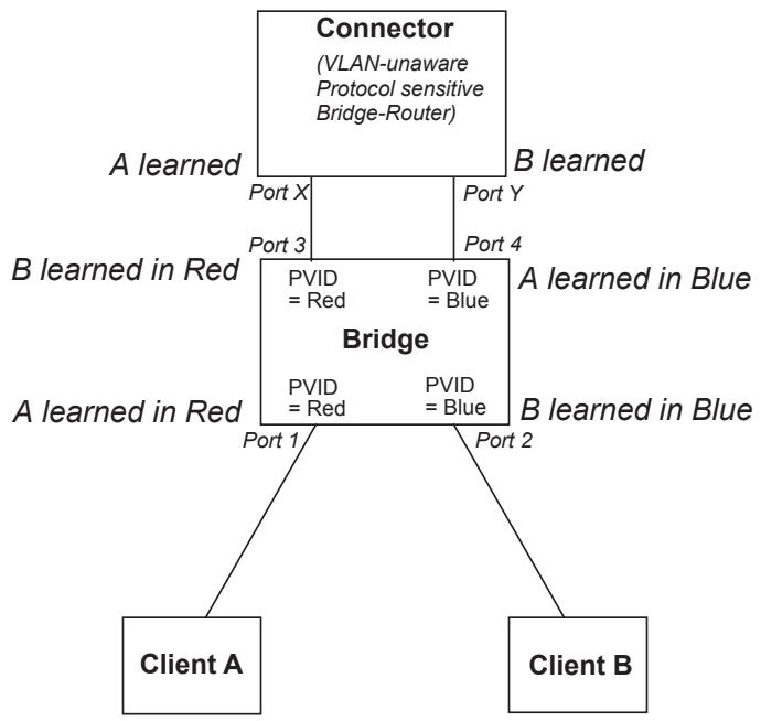
Figure F-1—Connecting independent VLANs—1
Clients A and B are connected via the protocol sensitive Bridge-Router (Connector), with an intervening VLAN Bridge. The fact that all Ports of the Bridge carry untagged traffic neatly conceals the fact that the Connector has the effect of connecting VLANs Red and Blue together with regard to bridged traffic. The Connector learns A and B in the same database, as it has no knowledge of VLANs Red and Blue. This prevents any traffic transmitted on the Red VLAN (Port X of the Connector) that is destined for A, from being bridged to Port Y and transmitted on the Blue VLAN.
The VLAN Bridge must keep its learning separate for Red and Blue; otherwise, the addresses of the two clients would be alternately learned on diagonally opposite Ports as, for example, traffic sourced by A reenters the Bridge on Port 4 having previously been seen on Port 1.
NOTE—This example assumes that the spanning tree protocol is disabled in the Connector, so that the VLAN Bridge does not attempt to suppress the loop that apparently exists if VLANs are not taken into account.
A simpler example can be constructed, with a single Port connecting the Connector and the VLAN Bridge, if the Connector is itself VLAN-aware and transmits and receives only VLAN-tagged traffic. In this case, the Connector would allocate a single FID for use by Red and Blue. This is shown in Figure F-2.
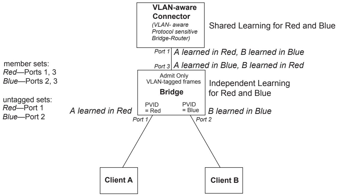
Figure F-2—Connecting independent VLANs—2
F.1.2 Duplicate MAC addresses
The simplest example of a need for IVL occurs where two (or more) distinct devices in different parts of the network reuse the same individual MAC address, or where a single device is connected to multiple LANs, and all of its LAN interfaces use the same individual MAC address. This is shown in Figure F-3.
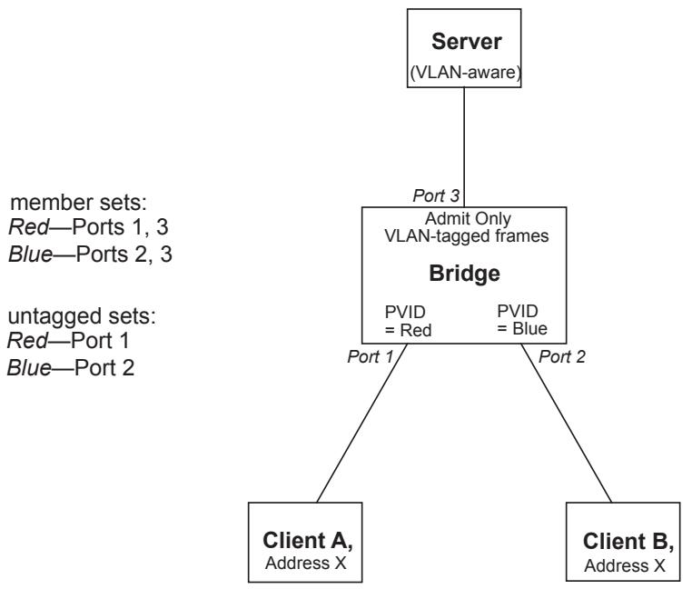
Figure F-3—Duplicate MAC addresses
The example shows two clients with access to the same server; both clients are using the same individual MAC address, X. If the Bridge shares learning between VLAN Red (which serves Client A) and VLAN Blue (which serves Client B), i.e., the Bridge uses the same FID for both VIDs, then Address X will appear to move between Ports 1 and 2 of the Bridge, depending on which client has most recently transmitted a frame. Communication between these Clients and the server will therefore be seriously disrupted. Assignment of distinct FIDs for Red and Blue ensures that communication can take place correctly.
Hence, in order to construct this particular VLAN configuration, either an IVL Bridge or an SVL/IVL Bridge would be required.
F.1.3 Asymmetric VLANs and Rooted-Multipoint connectivity
A primary example of the requirement for SVL is found in “asymmetric” uses of VLANs. Under normal circumstances, a pair of devices communicating in a VLAN environment will both send and receive using the same VID; however, there are some circumstances in which it is convenient to make use of two distinct VIDs, one used for A to transmit to B and the other used for B to transmit to A. Examples of such applications include configuring multi-netted servers, and configuring rooted-multipoint services.
F.1.3.1 Multi-netted Server
An example of Multi-netted Server application of asymmetric VLANs is shown in Figure F-4. Note that
a) In the example, the server and both clients are assumed to be VLAN-unaware devices, i.e., they transmit and receive untagged frames only;
b) The ingress classification rules assumed by the example are as defined in this standard, i.e., Portbased classification only;
c) The configuration shown can only be achieved by management configuration of appropriate values in Static VLAN Registration Entries (8.8.10) in order to configure the indicated member sets and untagged sets.
member sets:
Purple - Ports 1 and 2
Red - Port 3
Blue - Port 3
untagged sets:
Purple - Ports 1 and 2
Red - Port 3
Blue - Port 3
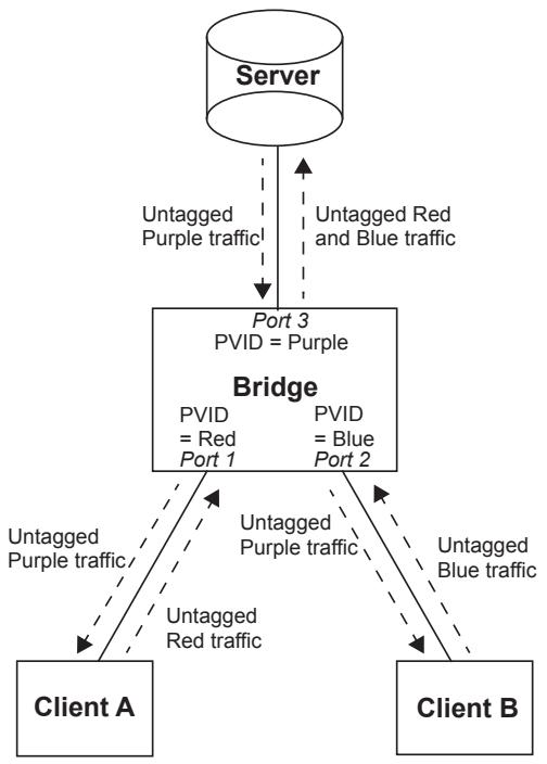
Figure F-4—Asymmetric VID use: “multi-netted server”
In the example, Port-based tagging and an asymmetric VLAN configuration is used in order to permit Clients A and B access to a common server, but to prohibit Clients A and B from talking to each other. Examples of where this type of configuration might be required are if the clients are on distinct IP subnets, or if there is some confidentiality-related need to segregate traffic between the clients.
Client A transmits to the server via Port 1, which will classify this traffic as belonging to VLAN Red; the Bridge therefore learns Client A’s MAC address on Port 1 in association with VLAN Red’s VID. The Server transmits its responses to Client A via Port 3, which classifies the return traffic as belonging to VLAN Purple. If individual MAC address learning is configured in the Bridge such that learning is independent between Red and Purple (the VIDs for Red and Purple are allocated to distinct FIDs), then the Bridge will have no knowledge of A in VLAN Purple and will therefore flood the server’s responses to Client A on both Port 1 and Port 2. Conversely, if the VIDs for Red and Purple are defined to share the same FID, then the address information learned in Red will be available for use in forwarding the Purple traffic, and the responses to Client A are forwarded only through Port 1.
Similarly, there is a need in this configuration for Blue and Purple to share learning information; hence, in order for this configuration to achieve its objectives, the Red, Blue, and Purple VIDs must be allocated to the same FID in the Bridge.
Hence, in order to construct this particular VLAN configuration, either an SVL Bridge or an SVL/IVL Bridge would be required.
NOTE—The example has been deliberately simplified; in practical applications, the central Bridge would likely be replaced by a number of VLAN Bridges, interconnected with links that would carry the traffic between clients and server as VLAN-tagged frames, with VLAN-tagging and untagging occurring only at the “edge” Ports of the network. An alternative approach to the one described here could also be achieved either by using a VLAN-aware server or by use of more sophisticated ingress classification rules.
F.1.3.2 Rooted-Multipoint
An example of a rooted-multipoint application of asymmetric VLANs is shown in Figure F-5. The defining characteristic of a rooted-multipoint service is that all Bidge Ports that provide access points to the service are designated as either a Root Port or a Leaf Port , and that the Root Ports can communicate with all other Root Ports and all Leaf Ports, whereas the Leaf Ports can communicate with all Root Ports but not with any other Leaf Ports. Services based on rooted-multipoint connectivity are also known as “E-TREE” services as defined in MEF 10.2. Rooted-multipoint connectivity would typically be used by an Internet access provider or a video content provider, where the provider of the service connects to Root Ports, and the subscribers of the service connect to Leaf Ports. This connectivity can be achieved with the “multi-netted server” configuration shown in Figure F-4, but it consumes one VID per subscriber. Figure F-5 shows an alternative that uses just two VIDs: a “Trunk” VID for traffic from Root Ports to Leaf Ports (and to other Root Ports) and a “Branch” VID for traffic from Leaf Ports to Root Ports.
To allow the servers to communicate with all other servers and all subscribers, and to allow the subscribers to communicate with all servers but not with other subscribers, the rooted-multipoint connectivity requires the following configuration:
a) The server(s) and all subscribers transmit and receive untagged frames only. Note that for a rootedmultipoint service on a PBN, this means the frames do not contain S-TAGs at the customer service interface (in other words, the User Network Interface (UNI)). Therefore, rooted-multipoint can be supported at Port-based service interfaces (15.3) and C-tagged service interfaces (15.4).
b) The ingress C-VLAN classification may be Port-based or Port-and-Protocol-based for rootedmultipoint on CBNs. The ingress S-VLAN classification may be Port-based or C-TAG-based for rooted-multipoint on PBNs.
c) In Customer Bridges and S-VLAN Bridges, the indicated values of the member sets and untagged sets (8.8.10) are achieved by management configuration of Static VLAN Registration Entries (8.8.2). In Provider Edge Bridges the Trunk and Branch VIDs are also mapped to the appropriate CNP/PEP pair by management configuration of the PEP Table (12.13.2.4, ieee8021PbEdgePortTable 17.6.1.2). Note that connectivity between Leaf Ports is blocked by not including Leaf Ports in the member set associated with the Branch VID.
In Customer Bridges and S-VLAN Bridges the indicated values of the PVID parameters are configured by management. In Provider Edge Bridges the equivalent configuration is achieved by management configuration of the C-VID Registration Table (12.13.2.2, ieee8021PbCVidRegistrationTable 17.6.1.2).
e) The Enable Ingress Filtering parameter (8.6.2) is reset, i.e., ingress VLAN filtering is disabled, on Leaf Ports.
f) The Trunk and Branch VIDs share the same FID (to enable SVL).
member sets:
Trunk - Ports 1,2 and 3
Branch - Port 3
untagged sets:
Trunk - Ports 1, 2 and 3
Branch - Port 3
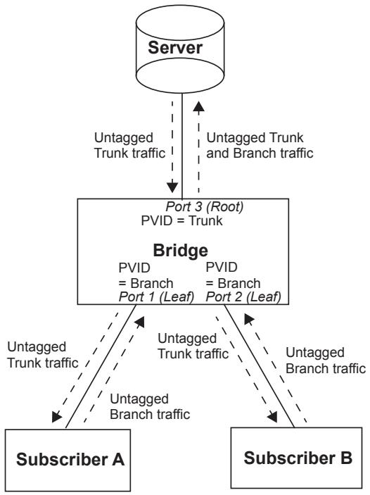
Figure F-5—Asymmetric VLAN use: “Rooted-Multipoint”
NOTE 1—The example has been deliberately simplified; in practical applications, the central Bridge would likely be replaced by a number of VLAN Bridges, interconnected with links that would carry the traffic between subscribers and servers as VLAN-tagged frames, with only the Root and Leaf Ports of the network carrying untagged frames.
Rooted-multipoint services can be carried on PBBNs by configuring Trunk and Branch S-VIDs as described above, with the Root and Leaf Ports at CNPs either at an I-component of a BEB, or at a Provider Edge Bridge of a PBN which then connects to the PBBN. The I-component of a BEB can then either map the Trunk and Branch S-VIDs to separate backbone service instances (i.e., mapped to separate I-SIDs) or bundle them into a single backbone service instance.
Rooted-multipoint connectivity can also be created on a PBBN by configuring Trunk and Branch B-VIDs as described above, with the Root and Leaf Ports at CBPs of a B-component in a BEB. One or more backbone service instances can then be mapped to the Trunk and Branch B-VIDs to take advantage of the rootedmultipoint connectivity.
As noted in bullet a) above, the configurations described above apply to scenarios where the ingress and egress frames at a Root or Leaf Port on a Customer Bridge or S-VLAN Bridge are untagged. Customer Bridges and S-VLAN Bridges that support both the VID Translation Table and Egress VID Translation Table (6.9) can support tagged ingress and egress frames at a Root or Leaf Port. Figure F-6 shows the configuration where the server(s) and subscribers transmit and receive tagged frames. The server uses VID R for frames associated with the rooted-multipoint service, and the subscribers use VIDs L1 and L2. The values of R, L1, and L2 could be, but are not necessarily, the same. The configuration of the Bridge(s) with Root and Leaf Ports are shown in the diagram. All Root and Leaf Ports are included in the member set of the Trunk and Branch VIDs, but not in the untagged set (including the Leaf Ports in the member set of the Branch VID allows ingress VLAN filtering to be enabled at these ports if desired). The VID translation at a Root Port ensures that ingress frames go to the Trunk VID, and egress frames come from both the Trunk and Branch VIDs. The VID translation at a Leaf Port ensures that ingress frames go to the Branch VID, and egress frames come from the Trunk VID (translating the Branch VID to 0xFFF on egress frames at Leaf Ports causes these frames to be discarded).
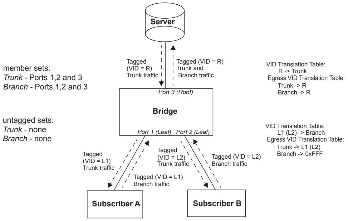
Figure F-6—Rooted-Multipoint with tagged interfaces
NOTE 2—The example has been deliberately simplified; in practical applications, the central Bridge would likely be replaced by a number of VLAN Bridges, interconnected with links that would carry the traffic between subscribers and servers as frames tagged with either the Trunk or Branch VID. VLAN translation occurs only at the Root and Leaf Ports of the network.
F.1.4 Shared learning and Shortest Path Bridging VID (SPBV) mode
SPBV mode uses shared learning among the set of SPVIDs that support a given SPBV VLAN. Each SPT Bridge supporting an SPBV VLAN is assigned a unique VID (SPVID) for transmitting VLAN frames into the SPT Region. This SPVID is registered by the ISIS-SPB control plane along an SPT rooted at the SPT Bridge to which it is assigned. The SPTs determined by ISIS-SPB provide symmetric bidirectional paths (i.e., congruent paths) between any pair of SPT Bridges within an SPT Region. The congruency of the paths is essential to allow shared learning. Shared learning is required because frames forwarded from a given SPT Bridge will contain a different SPVID from frames being forwarded to that SPT Bridge.
Figure F-7 shows an example of a simple SPBV VLAN operating in an SPT Region comprising three Bridges A, B, and C. Each of the Bridges is assigned an SPVID, in this example using the same letter designation as the Bridge to which it is assigned. ISIS-SPB maintains the VID member sets such that the SPVID of an SPT Bridge follows an SPT rooted at that particular SPT Bridge. The SPT includes all boundary ports participating in the SPBV VLAN (in this example the ports connected to stations A, B, and C).
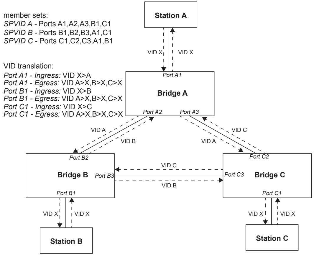
Figure F-7—SPBV VLAN Shared Learning and VID Translation
Shared learning is used among all the SPVIDs belonging to the SPBV VLAN. This enables the filtering information learned from frames transmitted from a Bridge (with that Bridge’s SPVID) to be applied to frames being transmitted to that Bridge from other Bridges using the other Bridges’ SPVIDs. For example, a frame sent from station A to station B will be transmitted by Bridge A using SPVID A. At Bridge B the frame’s source address will be learned at port B2. When station B later sends a frame to station A, Bridge B will assign the frame SPVID B. Shared learning enables Bridge B to use the MAC address previously learned from the frame with SPVID A to filter the frame with SPVID B to transmit only on port B2.
Enhanced VID translation capabilities allow a single VID to be used for VLANs on boundary ports connected to an SPT Region even though many SPVIDs with shared learning are used within the SPT Region. In this example stations A, B and C all use VID X. At each boundary port ingress translation is set to translate the external VID (usually the Base VID) to the SPVID for the Bridge on which the boundary port resides. Egress VID translation is set to translate all the SPVIDs belonging to the SPBV VLAN to the external VID.
F.1.5 Generic constraints on SVL and IVL use
This subclause describes the general constraints on the mapping of VIDs to FIDs, from the point of view of a given Bridge that learns from or forwards frames on a set of VIDs (the Bridge’s “active set” of VIDs). If
a) The individual MAC addresses associated with each point of attachment to the active set of VIDs are unique (i.e., the “Duplicate MAC Address problem” is not present), and
b) There is no Bridge or Bridge-like device that takes frames from one VID in the active set and subsequently transmits them on another VID in the active set, then
every VID in the active set may share the same FID; in other words, individual MAC address information learned in the context of any one VID may be used in forwarding decisions taken relative to any of the others, so the SVL approach can be used in that Bridge.
Furthermore, if
c) Each bidirectional, individual MAC-Addressed, conversation between pairs of end stations makes use of the same VID in both directions, then
every VID in the active set may be allocated a distinct FID (with the possibility of a little extra flooding as learning of addresses in the context of one VID does not contribute to forwarding decisions for that address relative to any other VID). Under these circumstances, rule b) may also be relaxed and restated as follows:
d) Frames associated with one VID in the active set may be received by (up to) one Bridge and transmitted using another VID in the active set, provided that there is no loop in such VLAN to VLAN forwarding, e.g., for a set of VIDs Red, Blue, and Green, there is no logical loop in copying frames between VIDs, such as copying from Red to Green by one Bridge, Green to Blue by another, and Blue back to Red by a third.
So
e) If rules a), b), and c) are true, and d) is false, for all VIDs in the active set, then either an SVL or an IVL Bridge can be deployed;
f) If rules a) and b) are true, and c) and d) are false for all VIDs in the active set, then only an SVL Bridge can be deployed;
g) If rules a) or b) or d) are false, and c) is true for all VIDs in the active set, then only an IVL Bridge can be deployed.
These conditions are all on the basis that they apply “for all VIDs in the active set.” Clearly, in more complex scenarios, some VIDs in the active set will have requirements that dictate SVL behavior on the part of a given Bridge, while others will have requirements that dictate IVL behavior. Under such circumstances, an SVL/IVL Bridge is required, allowing those VIDs that need to be shared to be mapped to a single FID, while those that need to be independent are mapped to distinct FIDs. Needless to say, wherever an SVL or IVL Bridge can be deployed, it can successfully be replaced by an appropriately configured SVL/IVL Bridge.
Annex G
(informative)
MAC method-dependent aspects of VLAN support
G.1 Example tagged IEEE 802.3 Ethertype-encoded frame format
Figure G-1 provides an illustrative example of a single tagged EtherType-encoded frame format as used in an Ethernet to Ethernet Bridge. This illustration is only of the simplest case, that is, a single-level, fixed-size tagging between identical MACs.49
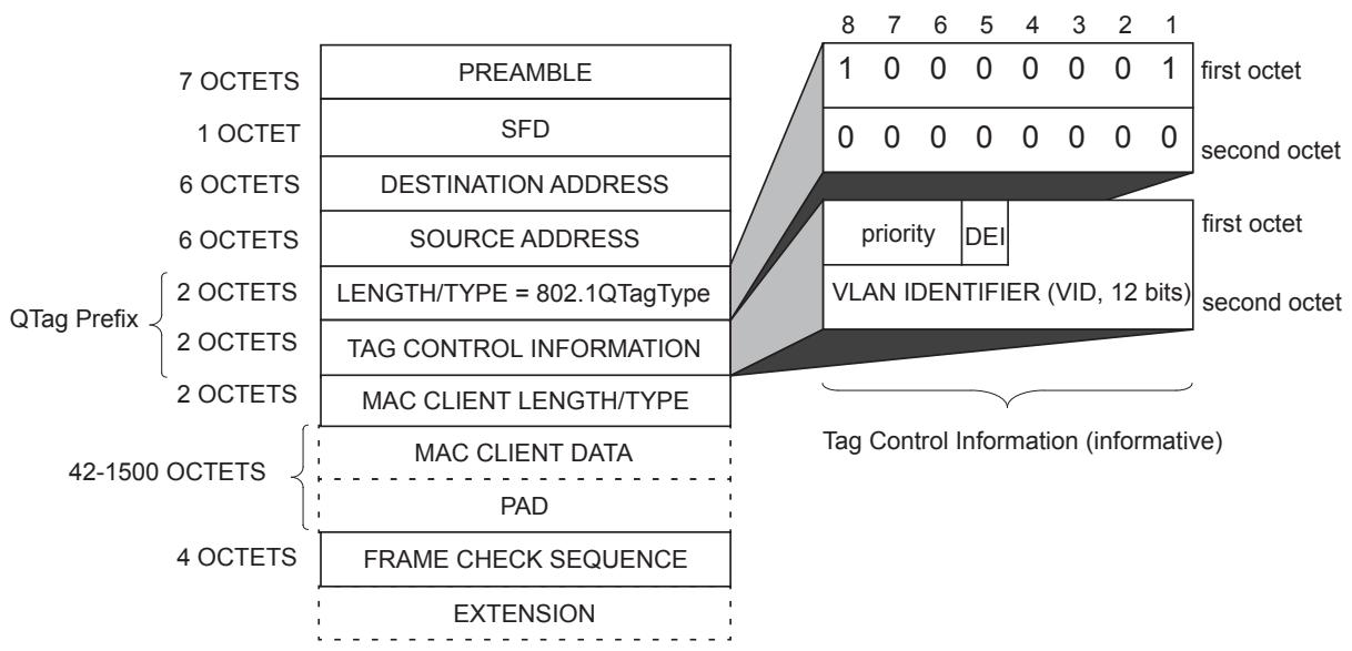
Figure G-1—Example of IEEE 802.3 MAC frame format
G.2 Padding and frame size considerations
G.2.1 Treatment of PAD fields in IEEE 802.3 frames
The minimum frame size constraint placed on IEEE 802.3/Ethernet frames requires frames to carry zero or more pad octets following the MAC client data, in order to ensure that no frame of total length less than 64 octets is transmitted on the medium. This requirement means that frames whose overall length would otherwise be less than 64 octets in length have (64-len) octets of padding added after the MAC client data, where len is the size of the frame before padding.
When tagged frames are transmitted by a Bridge on an IEEE 802.3 MAC, there are two permissible approaches, as follows:
a) Keep the minimum frame size generated by the Bridge equal to 64 octets. This implies that the number of pad octets in a received untagged IEEE 802.3 frame would be reduced by up to 4 octets when that frame was tagged;
b) Adopt a minimum tagged frame length of 68 octets. This implies that the number of pad octets in a received untagged IEEE 802.3 frame would not be adjusted when tagging such frames; equally, if subsequently untagged, no pad adjustment would be necessary before transmission on IEEE 802.3/ Ethernet.
There is a similar choice to be made in end stations that generate tagged frames:
c) In some existing implementations, the decision about whether pad octets are needed will be made at a point where it is impractical to distinguish between tagged and untagged frames. In these cases, the end station will use a minimum frame size of 64 octets for all frames;
d) In other cases, the padding decision will be taken at a point before it is known whether the frame will be transmitted tagged or untagged. In these cases, the end station will use a minimum tagged frame size of 68 octets and a minimum of 64 octets for untagged frames.
These approaches are all consistent with the IEEE 802.3 frame specification.
The implication is that, for correct operation on IEEE 802.3/Ethernet, all devices have to be capable of correctly handling tagged frames of less than 68 octets in length (G.2.3).
G.2.2 Maximum PDU size
VLAN tagging of an untagged frame, or relaying frames in tagged frame format, can result in an increase in the length of the original frame. If transmission of a given frame in tagged frame format through a given destination Port would result in violation of the maximum PDU size for the destination MAC method, the Bridge discards the frame for that destination Port.
NOTE—Violation of the maximum PDU sizes for destination MAC methods can produce undefined results in networks that contain devices that adhere strictly to these maxima, or in MAC methods where these maxima are inherently constrained by the operation of the MAC method itself (e.g., constrained by timing considerations in the MAC state machines).
IEEE Std 802.3 defines an extension to the normal IEEE 802.3 maximum frame size for the specific purpose of accommodating the additional octets of the VLAN tag header. The example frame translations in this annex make use of this extension to the IEEE 802.3 frame size.
G.2.3 Minimum PDU size
VLAN untagging of a tagged frame results in the original frame decreasing in length.
Where the destination MAC is Ethernet:
a) If untagging a given frame would result in violation of the minimum frame length requirements of Ethernet, the Bridge is required to adjust the PAD field to ensure that the frame length equals the minimum length of 64 octets (G.2.1);
b) If a frame is transmitted in tagged frame format, the Bridge may adopt a minimum tagged frame length of either 64 or 68 octets, as an implementation option. If the latter is chosen, the Bridge adjusts the size of the PAD field on transmission for any tagged frame that is less than 68 octets in length (G.2.1).
Annex H
(informative)
Interoperability considerations
VLAN Bridges are able to interoperate in networks with other VLAN Bridges. However, the VLAN-based filtering service defined in this standard, as provided in the context of a single spanning tree for the network, involves some constraints on the network topology and individual device configurations that differ from the set of constraints that apply to the building and configuration of networks based only on MAC Bridges.
In addition, VLAN Bridges are able to interoperate with MAC Bridges, as well as with both priority-aware and VLAN-aware end systems. Both the VLAN-based filtering service and the tag insertion and removal service specified in this standard cause constraints on intermixed network topologies and device configurations that again differ from the building and configuration of networks containing MAC Bridges.
The implications of certain device configurations may not be immediately apparent from the technical detail of this standard. In order to clarify the nature of the additional constraints, H.1 through H.4
a) Describe the basic requirements for interoperability;
b) Discuss those requirements in the context of homogeneous and heterogeneous configurations, with examples of some of the problems that can occur if these requirements are not adhered to.
H.1 Requirements for interoperability
Two primary aspects of the configuration of a network are of concern from the point of view of interoperability:
a) Establishing a consistent view of the static filtering configuration of Bridges in the network;
b) Ensuring that untagged frames are VLAN-tagged (and that the tag is subsequently removed) consistently regardless of spanning tree reconfigurations.
H.1.1 Static filtering requirements
Static filtering controls allow the network administrator to impose a level of control over the permitted connectivity in the network, by setting static MAC address filters in the FDBs of Bridges, and by controlling the extent of particular VLANs by manipulation of Static VLAN Registration Entries (8.8.2).
In order to ensure that end station-to-end station connectivity (or the lack of it) is consistent in all possible spanning tree configurations, any static filters need to be established taking account of the full mesh topology of the physical interconnections between Bridges in the network, not just the “normal” spanning tree topology to which the network is configured when all Bridges and LANs are operating correctly. An example of the consequences of failure to establish consistent controls for static VLAN filtering is given in H.2.1.
H.1.2 Configuration requirements for VLAN-tagging
VLAN Bridges classify incoming untagged frames by applying either a Port-based tagging rule on ingress that uses the PVID for the reception Port as the VLAN classification for such frames or a Port-and-Protocolbased rule that uses the frame’s ULP to select one of a port’s VIDs. Maintaining consistent connectivity between any pair of end stations that are on the same VLAN, and where one or both of those end stations is VLAN-unaware, requires that
a) All VLAN Bridge Ports that are connected to the same LAN apply a consistent set of ingress rules (8.6);
b) All VLAN Bridge Ports that are connected to the same legacy region of a network apply a consistent set of ingress rules;
c) All VLAN Bridge Ports that serve LANs to which members of the same VLAN are (or can be) attached apply a consistent set of ingress rules.
A legacy region of a network consists of any set of LANs that are physically interconnected via MAC Bridges. A legacy region has the property that, by appropriate configuration of the spanning tree, a spanning tree path could be created between any pair of LANs in the region such that the path would pass only through MAC Bridges.
NOTE—In case b), spanning tree reconfiguration within the legacy region can change the logical connectivity between the VLAN Bridge Ports and the LANs that they (directly or indirectly) serve. Hence, a spanning tree reconfiguration could result in any end stations connected to the legacy region being serviced via any VLAN Bridge Port. In effect, such a reconfiguration reduces case b) to case a). Figure H-2 and Figure H-3 give examples of this type of configuration. In Figure H-2, the legacy region consists of all three LANs and both MAC Bridges. In Figure H-3, the legacy region consists of the MAC Bridge and both LANs to which it is attached. An example of case c) is where an end station attached to a leaf LAN is in the same VLAN as a server that is attached to a distinct LAN, i.e., all possible spanning tree paths between the two stations pass through a VLAN-aware region of the network.
The essence of what these rules express is that if a given untagged frame belongs on a given VLAN, then the classification and tagging behavior of any VLAN Bridges that are required to tag that frame needs to be the same, regardless of the logical connectivity that is created by the spanning tree configuration of the network. Examples of the consequences of failure to apply these rules appear in H.3 and H.4.
H.2 Homogenous VLAN-aware networks
This standard requires new considerations in building a network in which all Bridges are VLAN Bridges. The arbitrary plug-and-play capability of MAC Bridges in creating a network topology is restricted when making use of the VLAN extensions defined in this standard.
H.2.1 Consistency of static VLAN filtering
In order for stations that are members of a given VLAN to be able to reach other members of the same VLAN elsewhere in the network, all Bridge Ports that are part of the spanning tree active topology (i.e., all Bridge Ports that are in a forwarding state) connecting the stations must be included in the member set (8.8.10) for the VID that identifies that VLAN. In order for this connectivity to be independent of any reconfiguration of the spanning tree topology, all paths among those stations, both forwarding and blocked, must have this characteristic. Use of management controls to manipulate the member set (e.g., filters for security) must be applied in a manner consistent with requirements of the full mesh topology of the network.
An inconsistency occurs, for example, if a VID is restricted from an active path, but not from a redundant path currently blocked by the operation of spanning tree. Should a spanning tree reconfiguration enable the previously blocked path, the restriction will no longer be in place. In the reverse, a spanning tree reconfiguration may suddenly impose a restriction that had not existed. A common use of such management restriction will likely arise from managers who make use of an “access” port construct. An access port may be a port that is absent from the member set (8.8.10) for all VIDs but the untagged, default VID. Should such an access port become the active connection between two portions of the network as a result of a spanning tree reconfiguration, all VLANs but the one identified by the default VID will be partitioned at that point in the topology.
In Figure H-1, the trunk style link and access style link cause a loop through the left and right portions of the network. STP will block one or the other. Should the spanning tree block at point #1, all 2000 users may communicate on any of the 50 VLANs. However, should the spanning tree block at point #2, the left and right portions of the network will be partitioned on all VLANs excepting VLAN 3 (the VLAN carried via the access style link.)
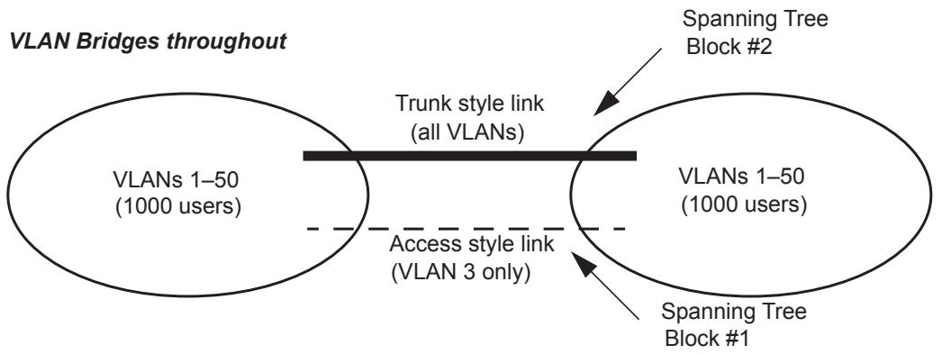
Figure H-1—Static filtering inconsistency
H.2.2 Consistent view of the “untagged VLAN(s)” on a given LAN
In the Port-based VLAN model defined in this standard, the PVID for a Bridge Port provides the VLAN classification for all frames on the attached LAN that are received in untagged form. Any LAN with more than one VLAN Bridge attached has such an “untagged VLAN” for each VLAN Bridge. No explicit requirement that PVID be consistent for all VLAN Bridges on the same LAN, nor mechanism to ensure such, has been included in this standard.
Similarly, in the Port-and-Protocol-based VLAN model defined in this standard, one member of the VID Set for a Bridge Port provides the VLAN classification for all frames on the attached LAN that are received in untagged form with a particular ULP. Any LAN with more than one such VLAN Bridge attached has such a set of “untagged VLANs” for each VLAN Bridge. No explicit requirement that these be consistent for all VLAN Bridges on the same LAN, nor mechanism to ensure such, has been included in this standard.
Consider the case of a LAN to which are attached three VLAN Bridges, each of which is using Port-based classification and is capable of transmission of untagged frames onto the LAN. An untagged frame placed on that LAN by any one of the VLAN Bridges will be associated by each of the other two VLAN Bridges with its own configured PVID for its reception Port on that LAN. The VLAN model requires that each frame have a unique VLAN association, and that association is represented by a single, global VID value. Therefore, it follows that all VLAN Bridges on that LAN must make use of the same classification rules (in this case, the same PVID) for their ports connected to that LAN.
It has been suggested that in the special case of a direct point-to-point connection between two VLAN Bridges or other VLAN-aware devices, other rules might apply. No mechanism for identifying such links has yet been suggested.
This creates a configuration challenge for installers of VLAN Bridges that conform to this standard. Initial management configuration of the VLAN Bridges (the setting of PVIDs, VID Sets, and Protocol Group Databases) must be made consistent among the VLAN Bridges, in a manner that takes into account the actual physical topology. Changes to the physical topology may require specific changes to the configuration of all affected switches. These requirements effectively disallow a plug-and-play installation as supported by MAC Bridges, unless all VLAN Bridges are left with their default Port-based classification rules and with each PVID = 1.
H.3 Heterogeneous networks: Intermixing MAC Bridges (M) and VLAN Bridges (V)
This subclause discusses networks in which VLAN Bridges are intermixed with MAC Bridges.
A principal limitation in intermixing VLAN Bridges with MAC Bridges is that the VLAN filtering services are not universally available throughout the network. Also, services for the insertion and removal of tags are not universally available. Furthermore, spanning tree reconfigurations may cause filtering services, as well as tag insertion and removal services, to become available or become unavailable independent of actions of affected users.
H.3.1 Example: Adding a VLAN Bridge to provide filtering to a MAC Bridged Network
Example problems can be shown with the following topology diagrams. Figure H-2 includes one V Bridge and two M Bridges:
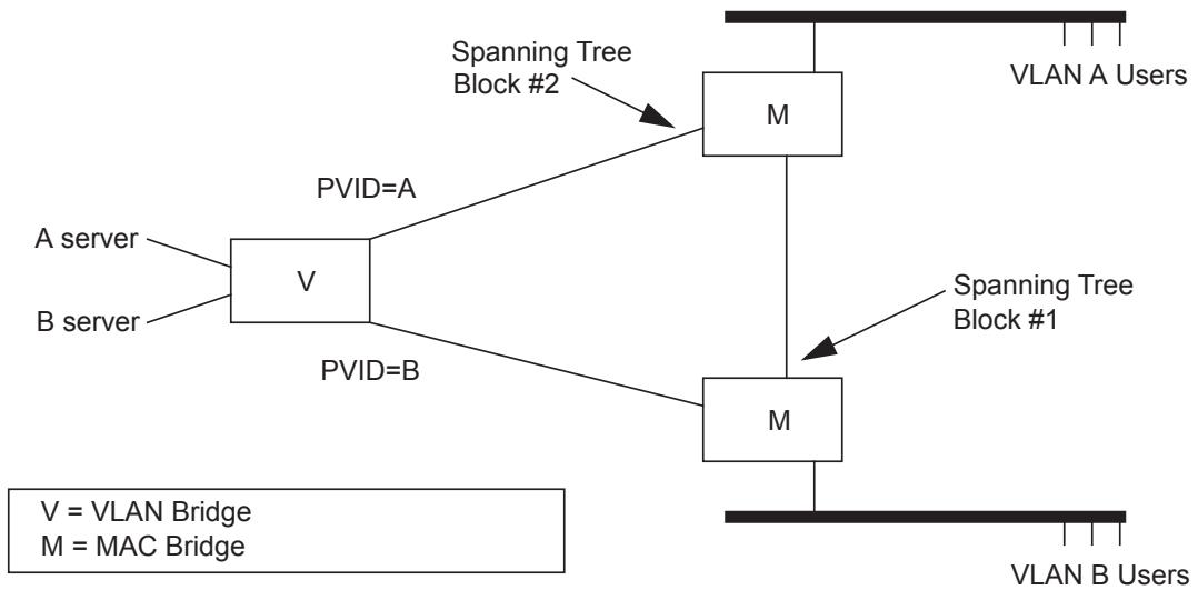
Figure H-2—Interoperability with MAC Bridges: example 1
If the spanning tree protocol determines to break the loop among the three Bridges by blocking at point #1, connectivity within each VLAN is as desired. However, should the block occur at point #2, traffic from VLAN A users will pass through both M Bridges and be treated as VLAN B traffic upon arrival in the V Bridge. Connectivity to the A server will be lost for the A users.
H.3.2 Example: Adding a MAC Bridge to a (previously) Homogenous VLAN Bridged Network
A similar problem, demonstrating the impact of placing an M Bridge within an otherwise homogenous V topology, can be shown by the configuration in Figure H-3. This figure includes two V Bridges and adds a single redundant M Bridge:
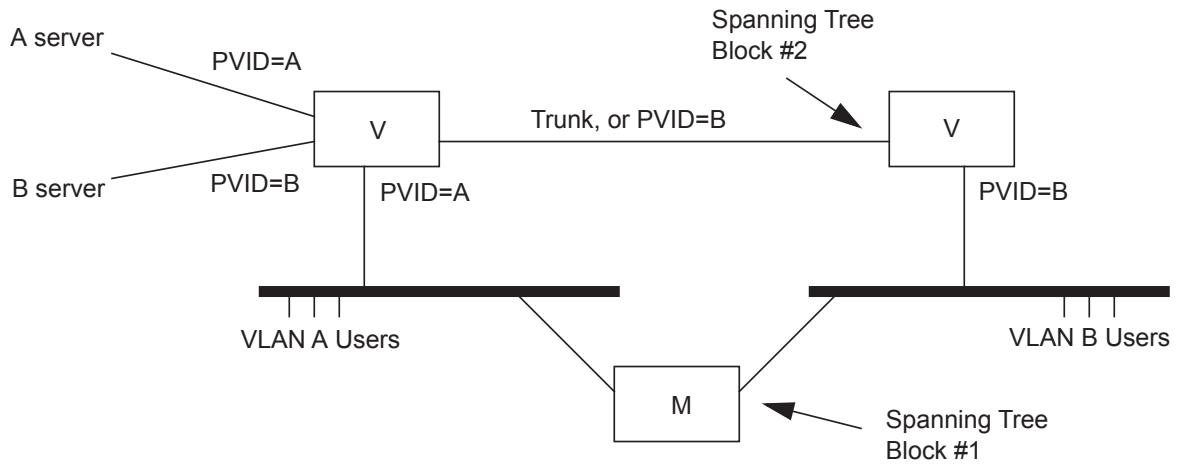
Figure H-3—Interoperability with MAC Bridges: example 2
If STP determines to break the loop among the three Bridges by blocking at point #1, connectivity within each VLAN is as desired. The two V switches operate as expected. A and B VLAN frames are VLANtagged on arrival in either V Bridge and forwarded only to the appropriate servers. Now suppose an STP reconfiguration results in a block at point #2, but not at #1. This redirects VLAN B user traffic through the M Bridge. VLAN B users no longer have their traffic identifiably distinct from VLAN A. An immediate consequence is that the VLAN B users will no longer have access to the “B server.”
H.4 Intermixing Port-based classification and Port-and-Protocol-based classification or future enhancements in VLAN Bridges
Intermixing V Bridges with M Bridges has a direct analogue in the mixing of Bridges implementing only Port-based and Port-and-Protocol-based classification of frames in VLAN Bridged networks. This revision and potential subsequent editions of this standard extend the VLAN classification capabilities to support more sophisticated ingress rules for frame classification.
In VLAN configurations that use both Port-based and Port-and-Protocol-based VLAN classification, a Bridge that supports only Port-based VLAN classification will merge VLANs that would otherwise be classified separately by a Bridge that supports Port-and-Protocol-based VLAN classification. To get around this problem, it may be possible to dedicate specific Ports to specific protocols in Bridges that support only Port-based VLAN classification, as in the example shown in Figure H-4. However, such solutions may not be possible where there are multiprotocol end stations in the network.
H.4.1 Example: Intermixing Protocol-based ingress rules
Consider the case where Bridges implement a configuration mechanism to select between Port-based classification rules (a “V-Port Bridge”) and Port-and-Protocol-based rules (a “V-Port/Protocol Bridge”).
This case would allow, for example, for support for IP and IPX as distinct VLANs. The topology shown in Figure H-4 might apply when a V-Port/Protocol Bridge is added to a topology; otherwise, using only V-Port Bridges allows users of two protocols to participate in two separate VLANs.
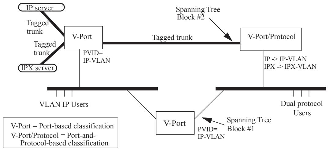
Figure H-4—Interoperability between Port-based and Port-and-Protocol-based classification
Consider this network, when STP has blocked at point #1, and not at #2. The upper V-Port Bridge operates as expected, and the V-Port/Protocol Bridge provides Port-and-Protocol-based classification for the frames received from the dual protocol users on the right-hand LAN. IP-VLAN and IPX-VLAN frames are VLANtagged on the trunks to and from the uppermost Bridges and servers. But if a STP reconfiguration should result in a block at point #2, but not at #1, activating traffic through the lower V-Port Bridge, dual protocol users will have all their traffic treated as part of the IP-VLAN. An immediate consequence is that the uppermost Bridge will no longer provide them access to the “IPX server.” It is the fact that the lower V-Port Bridge must have just one of the two VLANs configured for all untagged traffic, regardless of its protocol, that leads to this lack of connectivity.
H.4.2 Differing views of untagged traffic on a given LAN
Further challenges arise when one considers the case where several V Bridges, some implementing Port-based and some implementing Port-and-Protocol-based classification, all attach to the same LAN. Again, the rule that any given frame exists in exactly one VLAN requires that all of these Bridges be configured with consistent ingress rules. In this case, the V-Port Bridges will provide a least common capability, and this further requires common configuration of the PVID in the V-Port and V-Port/Protocol Bridges.
Annex I
(informative)
Priority and drop precedence
This standard allows management of priorities, flow metering, queue assignment, and queue servicing. This annex documents the rationale for the recommended and default priority to traffic class mappings in Table 8-4 and the encoding of priority and drop eligibility in Table 6-2 and Table 6-3.
Classification of user data frames into a small number of behavior aggregates, together with aggregate dependent forwarding behavior in each Bridge, allows signaling of application requirements to the network. Frame classification, aggregate bandwidth metering, policing, and drop precedence marking also facilitate network scaling and provision of services to independent customers through allocation of those functions to appropriate Bridges in the network.
While there are many possible ways to classify frames and to specify forwarding behaviors, it is widely appreciated that a set of well-known and easily understood defaults can facilitate interoperability and the deployment of services. The defaults described in this annex and supported by this standard were chosen to support integrated and differentiated services, to minimize the burden of management, to reduce the possibility of misconfiguration and out-of-order frame delivery, and to provide useful service without management in many networks.
This standard mandates support for strict priority frame transmission (8.6.6) but permits the use of additional traffic class-based transmission selection algorithms. The default assignments of frames to traffic classes on the basis of frame priority, as described in this annex, also support the use of frame priority to select general traffic class-based forwarding behavior.
NOTE—Annex Q provides references to the IETF work on integrated and differentiated services ([B17] through [B21] and [B23] through [B31]).
I.1 Traffic types
A full description of the QoS needs of applications and network services is too complex to be represented by a simple number 0 through 7. The pragmatic aim of traffic classification is to simplify requirements to preserve the high-speed, low-cost characteristics of Bridges. At the margin, potential bandwidth efficiency is traded for simplicity and higher speed operation—historically a good decision in the LAN.
The following list of traffic types, each of which can benefit from simple segregation from the others, are of general interest:
a) Network Control—characterized by a guaranteed delivery requirement to support configuration an maintenance of the network infrastructure.
b) Internetwork Control—in large networks comprising separate administrative domains there is typically a requirement to distinguish traffic supporting the network as a concatenation of those domains from the Network Control of the immediate domain.
c) Voice—characterized by less than 10 ms delay and, hence, maximum jitter (one way transmission through the LAN infrastructure of a single campus).
d) Video—characterized by less than 100 ms delay, or other applications with low latency as the primary QoS requirement.
e) Critical Applications—characterized by having a guaranteed minimum bandwidth as their primary QoS requirement and subject to some form of admission control to ensure that one system or application does not consume bandwidth at the expense of others. The admission control mechanism can range from preplanning of the network requirement at one extreme to bandwidth reservation per flow at the time the flow is started at the other.
f) Excellent $\mathrm { E f f o r t { - } o r \Sigma ^ { \mathrm { < } } C E O ^ { \mathrm { > } } s }$ best effort,” the best-effort type services that an information services organization would deliver to its most important customers.
g) Best Effort—for default use by unprioritized applications with fairness only regulated by the effects of $\mathrm { T C P } { \mathrm { ? } } \mathrm { s }$ dynamic windowing and retransmission strategy.
h) Background—bulk transfers and other activities that are permitted on the network but that should not impact the use of the network by other users and applications.
I.2 Managing latency and throughput
Use of priorities and queuing by traffic classes, each class encompassing one or more priorities, facilitates improvement and management of latency and throughput, allowing QoS goals to be supported at higher levels of network loading than would otherwise be possible.
Congestion, resulting in QoS degradation, is not equally likely at all Bridges in a network. Transient traffic patterns are likely to result in congestion in only a few Bridges at a time, while over an extended period, momentary congestion is more likely to occur in the network core than at Bridge Ports attached to one or a relatively small number of end stations. Use of fewer traffic classes for those Ports can lower the cost of implementation and management, and this standard facilitates the use of Bridges supporting differing numbers of classes within a single network that delivers a consistent set of QoS parameters for each frame priority level. Although the number of traffic classes supported by each Bridge Port along the path taken by a given flow of data can vary, the default mappings of priorities to classes ensures that frame ordering is preserved as required by 8.6.6.
With few classes, the focus is on meeting latency requirements—the bandwidth surplus required in a bursty data environment to guarantee sub-10 ms delays without a distinct traffic classification is uneconomically large. As the number of traffic classes that can be used increases, the focus shifts to managing throughput.
The simple default queue servicing policy defined in this standard, strict priority, supports latency management. Active management of bandwidth sharing necessarily requires some management.
I.3 Traffic type to traffic class mapping
Table I-1 is an example of how traffic types can be grouped to match the number of traffic class queues supported by a Bridge Port. Each grouping of types is shown as {Distinguishing type, Type, Type, . . .}. The “distinguishing type” is not treated in any way differently in a Bridge but is italicized here to illustrate, for any given number of queues, which traffic types have driven the allocation of types to classes.
Table I-1—Traffic type to traffic class mapping
<table><tr><td>Number of queues</td><td>Traffic types</td></tr><tr><td>1</td><td>{Best Effort, Background, Excellent effort, Critical Applications, Voice, Video, Internetwork Control, Network Control}</td></tr><tr><td>2</td><td>{Best Effort, Background, Excellent effort, Critical Applications}{Voice, Video, Internetwork Control, Network Control}</td></tr><tr><td>3</td><td>{Best Effort, Background, Excellent effort, Critical Applications}{Voice, Video}{Network Control, Internetwork Control}</td></tr><tr><td>4</td><td>{Best Effort, Background}{Critical Applications, Excellent effort}{Voice, Video}{Network Control, Internetwork Control}</td></tr><tr><td>5</td><td>{Best Effort, Background}{Critical Applications, Excellent effort}{Voice, Video}{Internetwork Control}{Network Control}</td></tr><tr><td>6</td><td>{Background}{Best Effort}{Critical Applications, Excellent effort}{Voice, Video}{Internetwork Control}{Network Control}</td></tr><tr><td>7</td><td>{Background}{Best Effort}{Excellent effort}{Critical Applications}{Voice, Video}{Internetwork Control}{Network Control}</td></tr><tr><td>8</td><td>{Background}{Best Effort}{Excellent effort}{Critical Applications}{Video}{Voice}{Internetwork Control}{Network Control}</td></tr></table>
The step-by-step breaking out of traffic types as more classes are available proceeds as follows:
a) With a single queue, there are no choices. All traffic is Best Effort.
b) To support integrated services in the presence of bursty best effort data, it is necessary to segregate all time-critical traffic. The amount of high-priority traffic will be restricted by the need to support low latency for Voice, which becomes the defining type for the additional queue.
c) Two queues may be adequate for Bridge Ports attaching to end stations. The stability of the network as a whole may be unaffected by the performance of configuration protocols on those Ports, and inband management of the Bridge is likely to occur through another Port. For Bridges within the network infrastructure, a further queue is used to isolate Network Control from the user data traffic.
d) Traffic for business Critical Applications is separated from Best Effort to allow a bandwidth guarantee to be provided.
e) The queue separation so far provided can support a large network. The next queue is allocated to distinguishing Internetwork Control traffic from local Network Control.
f) Background is separated from Best Effort to minimize the effect of bulk transfers on ordinary network use.
g) Excellent Effort is separated from Critical Applications, either to provide a simple superior service based on policy controlled access or to provide an additional segregated bandwidth guarantee.
h) The final provides increased network utilization as the higher bandwidth traffic associated with Video is no longer given the same latency guarantee as Voice.
This description is illustrative rather than definitive of the logic of allocating traffic types to classes. The mappings in Table 8-4 support the assignment of other semantics to each traffic type identified by priority values, e.g., the identification of all three illustrative types “Video,” “Critical Applications,” and “Excellent Effort” with ensured forwarding classes that provide segregated bandwidth guarantees. However, alternate semantics should take into account the service provided by Bridges with limited traffic class queuing; e.g., of the foregoing, only “Video” would receive priority treatment by default at a Bridge Port supporting queuing for only two classes.
I.4 Traffic types and priority values
Table I-2 shows the correspondence between traffic types and priority values used to select the defaults in Table 8-4. The default priority used for transmission by end stations is 0. Changing this default would result in confusion and likely in interoperability problems. At the same time, the default traffic type is definitely Best Effort. 0 is thus used both for default priority and for Best Effort, and Background is associated with a priority value of 1. This means that the value 1 effectively communicates a lower priority than 0.
Table I-2—Traffic type acronyms
<table><tr><td>Priority</td><td>Acronym</td><td>Traffic type</td></tr><tr><td>1</td><td>BK</td><td>Background</td></tr><tr><td>0 (Default)</td><td>BE</td><td>Best Effort</td></tr><tr><td>2</td><td>EE</td><td>Excellent Effort</td></tr><tr><td>3</td><td>CA</td><td>Critical Applications</td></tr><tr><td>4</td><td>VI</td><td>“Video,” < 100 ms latency and jitter</td></tr><tr><td>5</td><td>VO</td><td>“Voice,” < 10 ms latency and jitter</td></tr><tr><td>6</td><td>IC</td><td>Internetwork Control</td></tr><tr><td>7</td><td>NC</td><td>Network Control</td></tr></table>
Table I-3 summarizes Table I-1, showing just the defining traffic types. By maintaining the groupings of types established for a given number of queues for all less numbers, the table preserves the order of frames of any given type, independent of the number of queues.
This discussion of traffic types, and the suggested association of each with a priority value, differs from the similar discussion in Annex G of IEEE Std 802.1D-2004 [B10] and prior revisions of that standard. The latter was developed contemporaneously with IETF Intserv and predates Diffserv. The discussion in this annex better aligns with current practice; in particular, Voice is associated with priority 5, matching the setting of the relevant bits for Expedited Forwarding (EF) in the DSCP (Differentiated Services Code Point) for IP and in the common use of the EXP bits for MPLS. Standards for DSCPs are believed to be the prime reference for use of priority by end stations, and there is no direct change to the behavior of Bridge implementations conforming to this standard as a result of this change.
Table I-3—Defining traffic types
<table><tr><td>Number of queues</td><td colspan="8">Defining traffic type</td></tr><tr><td>1</td><td colspan="8">BE</td></tr><tr><td>2</td><td colspan="4">VO</td><td colspan="4">BE</td></tr><tr><td>3</td><td colspan="2">NC</td><td colspan="2">VO</td><td colspan="4">BE</td></tr><tr><td>4</td><td colspan="2">NC</td><td colspan="2">VO</td><td colspan="2">CA</td><td colspan="2">BE</td></tr><tr><td>5</td><td>NC</td><td>IC</td><td colspan="2">VO</td><td colspan="2">CA</td><td colspan="2">BE</td></tr><tr><td>6</td><td>NC</td><td>IC</td><td colspan="2">VO</td><td colspan="2">CA</td><td>BE</td><td>BK</td></tr><tr><td>7</td><td>NC</td><td>IC</td><td colspan="2">VO</td><td>CA</td><td>EE</td><td>BE</td><td>BK</td></tr><tr><td>8</td><td>NC</td><td>IC</td><td>VO</td><td>VI</td><td>CA</td><td>EE</td><td>BE</td><td>BK</td></tr></table>
The priority to traffic class mappings in Table 8-4 differ in one minor respect from those specified in prior revisions of this standard and in IEEE Std 802.1D-2004 [B10] and its prior revisions. Priority value 2 was previously described as ‘Spare’ and positioned lower than 0 (Best Effort) in priority order. This change may result in networks, including Bridges, conformant to prior revisions of this standard, and implementing four or more traffic classes, providing less-than-expected priority to traffic described in this annex as Excellent Effort, and misordering drop eligible traffic for Critical Applications. The change allows better use of the available traffic classes, given the low demand for two distinct priorities of lesser importance than Best Effort, and the best use of Priority Code Point when encoding drop eligibility.
I.5 Supporting the credit-based shaper algorithm
Table 34-1 and Table 34-2 define a set of recommended priority to traffic class mappings where the creditbased shaper algorithm (8.6.8.1) is supported by one or two of the available traffic classes; the recommended mappings shown are intended for use where priority 3 is used to support SR class A and priority 2 is used to support SR class B.
In order for the credit-based shaper algorithm to operate in the way it is intended, it is necessary to ensure that the shaper algorithm is supported on the numerically highest traffic class(es). Hence, if two traffic classes are used to support the shaper algorithm, it follows that the minimum useful number of traffic classes that a Port could support is three.
Table I-4 redraws Table I-3 for the case where only SR class B (SR-B) is supported. The defining traffic type for the numerically highest traffic class is SR-B in all cases. VI does not appear in this table since SR-B is used for the video traffic.
NOTE—When one or more SR classes are supported, the primary distinction being made is between traffic that requires bandwidth reservation and latency guarantees on the one hand, and different types of “best effort” traffic on the other. The audio and video traffic types identified in Table I-1 are therefore not applicable.
Table I-4—Defining traffic types—Credit-based shaper support of SR class B only
<table><tr><td>Number of queues</td><td colspan="8">Defining traffic type</td></tr><tr><td>2</td><td>SR-B</td><td colspan="7">BE</td></tr><tr><td>3</td><td>SR-B</td><td colspan="3">NC</td><td colspan="4">BE</td></tr><tr><td>4</td><td>SR-B</td><td colspan="3">NC</td><td colspan="2">CA</td><td colspan="2">BE</td></tr><tr><td>5</td><td>SR-B</td><td>NC</td><td colspan="2">IC</td><td colspan="2">CA</td><td colspan="2">BE</td></tr><tr><td>6</td><td>SR-B</td><td>NC</td><td colspan="2">IC</td><td colspan="2">CA</td><td>BE</td><td>BK</td></tr><tr><td>7</td><td>SR-B</td><td>NC</td><td colspan="2">IC</td><td>CA</td><td>EE</td><td>BE</td><td>BK</td></tr><tr><td>8</td><td>SR-B</td><td>NC</td><td>IC</td><td>VO</td><td>CA</td><td>EE</td><td>BE</td><td>BK</td></tr></table>
Table I-5 redraws Table I-3 for the case where SR classes A (SR-A) and B (SR-B) are supported in place of VO and VI. The defining traffic types for the two numerically highest traffic classes are SR-A and SR-B in all cases; for 4 through 8 traffic classes, the remaining traffic types are broken out in the same order as in Table I-3.
Table I-5—Defining traffic types—Credit-based shaper support of SR classes A and B
<table><tr><td>Number of queues</td><td colspan="8">Defining traffic type</td></tr><tr><td>3</td><td>SR-A</td><td>SR-B</td><td colspan="6">BE</td></tr><tr><td>4</td><td>SR-A</td><td>SR-B</td><td colspan="2">NC</td><td colspan="4">BE</td></tr><tr><td>5</td><td>SR-A</td><td>SR-B</td><td colspan="2">NC</td><td colspan="2">CA</td><td colspan="2">BE</td></tr><tr><td>6</td><td>SR-A</td><td>SR-B</td><td>NC</td><td>IC</td><td colspan="2">CA</td><td colspan="2">BE</td></tr><tr><td>7</td><td>SR-A</td><td>SR-B</td><td>NC</td><td>IC</td><td colspan="2">CA</td><td>BE</td><td>BK</td></tr><tr><td>8</td><td>SR-A</td><td>SR-B</td><td>NC</td><td>IC</td><td>CA</td><td>EE</td><td>BE</td><td>BK</td></tr></table>
I.6 Supporting drop precedence
It is often desirable to meter traffic from different users to ensure fairness or to meet bandwidth guarantees; however, dropping all traffic in excess of a committed rate is likely to result in severe under-utilization of the networks, because most traffic sources are bursty in nature. At the same time, it is burdensome to meter traffic at all points in the network where bandwidth contention occurs. One solution is to mark those frames in excess of the committed rate as drop eligible on admission to the network.
This standard allows drop eligibility to be conveyed separately from priority in VLAN tags so that all previously introduced traffic types can be marked as drop eligible. To provide compatibility with previous revisions of this standard while allowing drop eligibility to be conveyed in C-TAGs, this standard also allows a subset of the priorities to be conveyed along with drop eligibility marking for some of those priorities within the PCP field of both S-TAGs and C-TAGs.
I.7 Priority Code Point allocation
The Priority Code Point of VLAN tags allows encoding of five, six, seven, or eight distinct priorities, with a single level of drop eligibility on three, two, one, or zero of those priorities, respectively. Table 6-2 and Table 6-3 specify encoding and decoding for five through eight priorities. The tables are consistent with the following step-by-step reduction in the number of distinct priorities to provide drop eligibility for certain traffic types:
a) If eight distinct priorities are required, drop eligibility cannot be encoded in the Priority Code Point (but may be encoded in VLAN tags using the DEI).
b) Drop eligibility in support of QoS maintenance for traffic conforming to a committed rate is most effective when used to support time-critical traffic. If seven priorities, one of which can be marked as drop eligible, are required, then the traffic class queuing distinction between Voice and Video is sacrificed to providing drop eligibility for the combined traffic types. This does not preclude marking all Video traffic as drop eligible upon ingress to a network to provide the same guarantee to Voice as a distinct priority.
c) The distinctions between Critical Applications and Excellent Effort, and between Best Effort and Background traffic types, is removed to provide drop eligibility for Critical Applications and for Best Effort.
d) Although the use of four priorities, each with drop eligibility, is possible, it is not recommended. Combining Network Control with Internetwork Control could only serve to increase the guarantees provided to the latter at the expense of the former, which if not delivered threatens the stability of the overall network in any case. Moreover, both traffic types should be supportable with guaranteed bandwidth if the network is to be operated successfully.
Choosing first to combine Video and Voice, and then Critical Applications with Excellent Effort (for six queues), provides consistency with the allocation of priorities to traffic classes in the absence of drop eligibility. Bridges that do not implement drop eligibility, but are configured to use the same number or fewer traffic classes, will not misorder frames. If such a Bridge is configured to use only five traffic classes, and in accordance with Table 8-4, it will not misorder frames with a Priority Code Point encoded using any of the alternatives provided by Table 6-2.
I.8 Interoperability
Encoding of drop eligibility within the Priority Code Point, as opposed to explicitly with the DEI, provides interoperability with Bridges that are not capable of supporting the DEI. It also provides compatibility with the use of the MPLS EXP bits to convey priority and drop eligibility.
However, the requirement to provide different combinations of priorities with drop eligibility within the confines of the Priority Code Point means that priority and drop eligibility information can be lost for frames traversing a network if the combinations used on individual LANs differ. Use of the DEI does not suffer from this problem. In some cases, loss of drop eligibility information at the boundary between administrative domains risks impacting profile conformant traffic from some users with out-of-profile drop eligible traffic from others; in other cases, the drop eligible marking has already done its job (the next LAN, for example, might deliver traffic to a single customer). Without explicit management, a Bridge Port cannot decide, so the Require Drop Encoding parameter (8.6.7) has been provided.
If Bridges attached to the same LAN encode and decode the Priority Code Point differently, then incorrect priority values can be attributed and subsequent misordering of frames can occur. Misordering will not occur, with the recommended priority to traffic class mappings of Table 8-4 and the recommended Priority Code Point encoding and decoding in Table 6-2 and Table 6-3, if the Bridge performing the incorrect decoding assumes fewer priorities than are actually encoded or if all Bridges subsequently transited by the frame use the same number or fewer traffic classes than those used for the encoding. However, incorrect decoding will in all probability affect other service guarantees that the network is intended to support. If a Bridge can be used in a network that encodes drop eligibility in the Priority Code Point, and there is any likelihood of the Bridge being brought into service prior to the network-dependent service-level configuration, then five priorities, three with drop eligibility (5P3D encoding and decoding), should be used. Bridges that do not support drop precedence should be configured to support five or fewer traffic classes in the same circumstances.
The use of separate Priority Code Point Encoding and Priority Code Point Decoding Tables for each Bridge Port allows adaptation between the encoding scheme in one domain of the network and the encoding scheme used in another to be accomplished in only one of any pair of Bridges, each serving as a boundary of its domain, connected by a point-to-point LAN. However, if more than two Bridges are attached to a LAN, all need to use the same encoding so that each of its recipients can assign the correct priority to the frame.
The default Priority Code Point encoding and decoding, as documented in Table 6-2 and Table 6-3, are reproduced in Table I-6 and Table I-7, with the addition of the default allocation of priorities to traffic classes to the latter.
NOTE—The sequence of the columns for the priority values of 0 and 1 in Table I-6 and Table I-7 are reversed from the sequence in Table 6-2 and Table 6-3 in order to show the alignment with the traffic classes in Table I-3.
Table I-6—Priority Code Point encoding
<table><tr><td colspan="2">priority drop_eligible</td><td>7</td><td>7DE</td><td>6</td><td>6DE</td><td>5</td><td>5DE</td><td>4</td><td>4DE</td><td>3</td><td>3DE</td><td>2</td><td>2DE</td><td>0</td><td>0DE</td><td>1</td><td>1DE</td></tr><tr><td rowspan="4">PCP</td><td>8P0D</td><td>7</td><td>7</td><td>6</td><td>6</td><td>5</td><td>5</td><td>4</td><td>4</td><td>3</td><td>3</td><td>2</td><td>2</td><td>0</td><td>0</td><td>1</td><td>1</td></tr><tr><td>7P1D</td><td>7</td><td>7</td><td>6</td><td>6</td><td>5</td><td>4</td><td>5</td><td>4</td><td>3</td><td>3</td><td>2</td><td>2</td><td>0</td><td>0</td><td>1</td><td>1</td></tr><tr><td>6P2D</td><td>7</td><td>7</td><td>6</td><td>6</td><td>5</td><td>4</td><td>5</td><td>4</td><td>3</td><td>2</td><td>3</td><td>2</td><td>0</td><td>0</td><td>1</td><td>1</td></tr><tr><td>5P3D</td><td>7</td><td>7</td><td>6</td><td>6</td><td>5</td><td>4</td><td>5</td><td>4</td><td>3</td><td>2</td><td>3</td><td>2</td><td>1</td><td>0</td><td>1</td><td>0</td></tr></table>
Table I-7—Priority Code Point decoding
<table><tr><td colspan="2">PCP</td><td>7</td><td>6</td><td>5</td><td>4</td><td>3</td><td>2</td><td>0</td><td>1</td></tr><tr><td rowspan="4">priority drop eligible</td><td>8P0D</td><td>7</td><td>6</td><td>5</td><td>4</td><td>3</td><td>2</td><td>0</td><td>1</td></tr><tr><td>7P1D</td><td>7</td><td>6</td><td>4</td><td>4DE</td><td>3</td><td>2</td><td>0</td><td>1</td></tr><tr><td>6P2D</td><td>7</td><td>6</td><td>4</td><td>4DE</td><td>2</td><td>2DE</td><td>0</td><td>1</td></tr><tr><td>5P3D</td><td>7</td><td>6</td><td>4</td><td>4DE</td><td>2</td><td>2DE</td><td>0DE</td><td>0</td></tr><tr><td rowspan="8">number of traffic classes</td><td>1</td><td colspan="8">BE</td></tr><tr><td>2</td><td colspan="4">VO</td><td colspan="4">BE</td></tr><tr><td>3</td><td colspan="2">NC</td><td colspan="2">VO</td><td colspan="4">BE</td></tr><tr><td>4</td><td colspan="2">NC</td><td colspan="2">VO</td><td colspan="2">CA</td><td colspan="2">BE</td></tr><tr><td>5</td><td>NC</td><td>IC</td><td colspan="2">VO</td><td colspan="2">CA</td><td colspan="2">BE</td></tr><tr><td>6</td><td>NC</td><td>IC</td><td colspan="2">VO</td><td colspan="2">CA</td><td>BE</td><td>BK</td></tr><tr><td>7</td><td>NC</td><td>IC</td><td colspan="2">VO</td><td>CA</td><td>EE</td><td>BE</td><td>BK</td></tr><tr><td>8</td><td>NC</td><td>IC</td><td>VO</td><td>VI</td><td>CA</td><td>EE</td><td>BE</td><td>BK</td></tr></table>
Annex J
(informative)
CFM protocol design and use
J.1 Origin of CFM
Operations, Administration, and Maintenance (OAM) functions are a product of the world of telephony. As Ethernet, which has traditionally been an Enterprise network technology, expands into the realm of service providers, such useful notions as OAM become important. The OAM work going on in various standards bodies and in various vendors’ products can be classified into five groups:
a) Provider Edge OAM, as defined by IEEE Std 802.3-2012, Clause 57.
b) Ethernet Local Management Interface (E-LMI), as defined by MEF 16 [B46].
c) Underlying layers of OAM, such as MPLS OAM or ATM OAM,50 used on various sorts of emulated Ethernet links, carrying Ethernet frames as a higher layer.
d) Ethernet frames carrying End-to-End CFM PDUs, defined by this standard and by ITU-T Y.1731 (02/2008).
e) Network performance measurement, being defined by MEF and ITU-T, including ITU-T Y.1731.
CFM is one part of the whole OAM picture. It defines category d, Ethernet frames carrying End-to-End CFM PDUs, defined by this standard and by ITU-T Y.1731. This standard does not explicitly address the subject of the configuration or provisioning of Metro Ethernet services, but it does generate significant requirements on configuration and provisioning. Certain CFM PDU formats are also useful for network performance measurement (item e) and are defined in this standard. Additional PDUs for these operations are defined in ITU-T Y.1731.
Finally, unlike OAM in the telephony world, CFM does not address recovery from a loss of connectivity. That is the function of the various Layer 2 control protocols such as spanning tree (see Clause 13).
J.2 Deployment of CFM
It is critical to the early deployment of CFM that no hardware changes be required to achieve a significant level of CFM functionality. However, if the MEPs in a large number of large MAs issue Continuity Check Messages (CCMs) at the highest allowed rates, a Provider Bridge’s ability to generate and/or absorb these CCMs could be overwhelmed. To achieve its full potential, CFM could require hardware modifications to existing Provider Bridges.
a) The CFM shims shown in Figure 22-4 are an abstract concept. They have been defined so that it should be possible to emulate their functions on most existing platforms, though perhaps not at high rates of CFM PDU transmission and reception. Hardware assistance can enable higher CFM PDU rates and can enable the implementation of the Shared MP address model of operation instead of the Individual MP address model (J.6).
b) Directing CFM PDUs to the appropriate ports of a Provider Bridge could necessitate a separate MAC Address Registration Entry for each VID in the FDB. Some means whereby this large number of entries could be abstracted would reduce the load on the FDB and enable the use of a larger number of MD Levels.
c) The reception of an LBM and generation of the corresponding LBR have been defined in a manner that is amenable to implementation in hardware. If so implemented, then the providers’ ability to support a particular requirement for bandwidth in a service instance can easily be tested.
J.3 MD Level allocation alternative
There are eight Maintenance Domain Levels (MD Levels) as shown in Table J-1. In order to allow administrations to configure different Maintenance Domains in the same Bridge without having to resort to detailed inter-organizational agreements about which MD Levels are available for use, an administrator of a Maintenance Domain can decide which of three roles that Maintenance Domain will play: the “customer” role, the “service provider” role, or the “operator” role. The administrator would then be free to assign an MD Level to a Maintenance Domain within the range shown in Table J-1 according to the Maintenance Domain’s role. If two administrations can operate Maintenance Domains using the same role in one Bridge at different MD Levels.
Table J-1—Provider MD Level allocation
<table><tr><td>MD Level</td><td>7</td><td>6</td><td>5</td><td>4</td><td>3</td><td>2</td><td>1</td><td>0</td></tr><tr><td>Use</td><td colspan="3">customer</td><td colspan="2">service provider</td><td colspan="3">operator</td></tr><tr><td></td><td>Highest</td><td colspan="6"><- Higher lower -></td><td>Lowest</td></tr></table>
This method of MD Level allocation attempts to minimize the likelihood of incompatibilities caused by MD Level selection among separate administrative organizations that interconnect in a manner such that their MD Levels are visible to each other. Due to the addition of encapsulations such as VLAN tags that can hide one organization’s MD Levels from another, it is considered unlikely that the allocation method shown in Table J-1 will be necessary and that the method described in 22.3 will be sufficient.
J.4 Relationship of IEEE Std 802.1Q CFM to other standards
ITU-T Y.1731 (02/2008) is a compatible extension of CFM. Certain terminology is different between ITU-T Y.1731 and this standard. These differences are summarized in Table J-2.
Table J-2—IEEE / ITU-T terminology differences
<table><tr><td>IEEE Std 802.1Q</td><td>ITU-T Y.1731 (02/2008)</td></tr><tr><td>Maintenance Association (MA)</td><td>Maintenance Entity Group (MEG)</td></tr><tr><td>Maintenance Association Identifier (MAID)</td><td>Maintenance Entity Group Identifier (MEGID)</td></tr><tr><td>Maintenance Domain</td><td>(No such construct present)</td></tr><tr><td>Maintenance Domain Level (MD Level)</td><td>Maintenance Entity Group Level (MEG Level)</td></tr></table>
ITU-T Y.1731 includes a number of OpCodes in addition to the CCM, LBM, LBR, LTM, and LTR defined in this standard. ITU-T Y.1731 also specifies that the LBM can have a Group destination_address, in addition to the ability of using an Individual destination_address, as defined in this standard. It is for this reason that the MP Loopback Responder’s ProcessLBM() procedure (20.28.1) is required to respond to an LBM whose destination_address is the appropriate CCM Group address, even though this standard specifies no means for generating such a frame.
The MIP is defined as two MHFs in this standard, but not in ITU-T Y.1731. This is because ITU-T Y.1731 is not concerned with the details of the implementation.
ITU-T Y.1731 does not include an LTM Egress Identifier TLV (21.8.8) or LTR Egress Identifier TLV (21.9.7). For compatibility with early implementations of ITU-T Y.1731, this standard does not require that these TLVs be present on received LTMs or LTRs. However, this standard does require these TLVs to be transmitted in LTMs and LTRs.
ITU-T Y.1731 specifies that, if an LTM passes through MPs on both the ingress and egress ports, the TTL field of the LTM will be decremented twice. This standard requires, in that case, that the Bridge decrement the TTL field only once, and return a single LTR. The Y.1731 behavior is compatible with the LTR analysis presented in J.5, as long as each of the MPs that decrement the LTM’s TTL field also return an LTR. If a Bridge decremented the TTL twice, but returned only a single LTR, it would be impossible for the originating MEP to tell whether an LTR was lost in transit.
The Flags field (21.9.1) returned in the LTR contains two extra bits of information in this standard that are not in ITU-T Y.1731.
J.5 Interpreting Linktrace results
The LTR entries are retrieved from the Linktrace Database in the order the LTRs were received by the MEP. There is no way to determine when the last LTR has been received, except to wait for some number of seconds (e.g., long enough for a worst-case delay through the Bridged Network plus a few seconds), after the successful completion of the Transmit Linktrace Message command, before assuming that no further LTRs are likely to be received.
Because of the timer used by the LTR Transmitter state machine (20.5.1), the order in which the LTRs are received (time order) is likely to be different from the order of the MPs reached by the LTM as it was forwarded, MP by MP (path order). It is possible for an LTM to take more than one path, so that the LTRs report a tree, rooted at the originating MEP, rather than a simple linear series of zero or more MHFs terminating at a MEP or an MHF. If there are no network topology changes during the Linktrace operation, and if all systems’ behavior conforms to this standard, the following can be said about constructing this path tree from the list of LTR entries returned by the Read Linktrace Reply command:
a) Sort the returned LTR entries by decreasing value of ltrReplyTTL (20.41.2.2). The highest reported value is one less than the initial LTM TTL field value [item d) in 12.14.7.4.2] used in the Transmit Linktrace Message command, and corresponds to the first Linktrace Responder reached by the initial LTM. This Linktrace Responder resides in the same Bridge as the MEP, in the case of an LTM originated by an Up MEP. The next-lower value corresponds to the MHF(s) or MEP(s) reached by the first forwarded copy of that LTM, and so on. Any gaps in the sequence of Reply TTL values indicate lost LTRs.
b) The ltrNextEgressId variable (20.41.2.4) in every LTR entry returned from a given Transmit Linktrace Message command is unique among the LTR entries in a given LTM entry in the Linktrace database, since no Linktrace Responder transmits more than one copy of an LTM.
c) The ltrLastEgressId variable (20.41.2.3) in any LTR entry is unique only over those LTR entries with matching values of the ltrReplyTTL variable.
d) The ltrLastEgressId variable (20.41.2.3) in any LTR entry whose ltrReplyTTL variable is one less than the initial LTM TTL field also matches the original LTM’s LTM Egress Identifier TLV value, as returned from the Transmit Linktrace Message command [item c) in 12.14.7.4.3].
e) In the absence of lost LTRs, the ltrLastEgressId variable of any LTR whose ltrReplyTTL variable contains x will match the ltrNextEgressId variable of one of the LTRs whose ltrReplyTTL variable contains (x + 1). For LTR entry x, this match indicates which of the Linktrace Responders (x + 1) forwarded the LTM that was received by the Linktrace Responder that returned LTR entry x, and thus turns the list of LTR entries at each ltrReplyTTL value into a tree.
f) Along any given path from the root of the reply tree, the last reply can report any of the following conditions that terminate the forwarding of the LTM:
1) FwdYes bit of the ltrFlags variable is reset (false); or
2) TerminalMEP of the ltrFlags variable is set (true); or
3) ltrRelayAction variable contains the value, RlyHit; or
4) ltrReplyTTL variable contains 0.
g) If any path does not terminate with one of the conditions 1 through 3 in the previous item f), then either the initial LTM TTL field was insufficiently large to trace the complete path (and the last ltrReplyTTL variable of the end MP in the path contains 0), or a data frame addressed to the target MAC address of the LTM would be flooded after being forwarded from the Bridge that returned the last LTR in the path.
h) If the first Bridge encountered by the original LTM (which is the Bridge on which the LTM was originated, if originated from an Up MEP) would have flooded a data frame addressed to the target MAC address of the LTM, no LTRs will be returned in response to the LTM.
i) A gap in the ltrReplyTTL value sequence indicates the loss of (or failure to transmit) one or more LTRs. Similarly, a gap in the chain of ltrNextEgressId and ltrLastEgressId variables can be caused by the loss of LTRs. These conditions can make the construction of a reply tree impossible, if multiple LTRs have been returned with the same ltrReplyTTL value. If the last LTR along the path is lost, there is no gap in the ltrReplyTTL sequence to indicate the loss.
j) The Transmit Linktrace Message command can be reissued, and the resultant LTRs correlated with the results of a previous LTM, to improve the reliability of the results.
Diagnosing whether an anomalous result from a Read Linktrace Reply command, i.e., one that violates any of the prior assertions, is the result of ordinary frame loss (caused, e.g., by congestion), transitory network behavior (e.g., the loss of a LAN during the Linktrace procedure), a permanent malfunction (e.g., a Bridge is behaving in a noncompliant manner due to a hardware or software malfunction), or some other reason, is beyond the scope of this standard.
J.6 MP addressing: Individual and Shared MP addresses
It is stated in 21.3.2 that the source MAC address for a frame carrying a CFM PDU is the MAC address of the MP transmitting the PDU. This does not necessarily mean that the MP’s physical implementation is tied to a particular Bridge Port, and that the MAC addresses used in the frames carrying CFM PDUs are the MAC addresses of those Bridge Ports. While this method of MAC address assignment produces the best protection that this standard can provide for a network, it is not required that every MP use its Bridge Port’s MAC address.
CFM does not require the MPs configured on a single Bridge Port, e.g., all of the MPs illustrated in Figure 22-4, to have MAC addresses that are different from each other, nor does CFM require that they be the same. If the MPs in Figure 22-4 all have the same MAC address, CFM frames can be directed to the different MPs on that Bridge Port based on VID and MD Level. Choices can be made, however, with regard to whether MPs on different Bridge Ports can share the same MAC address. Two models are presented in this subclause for the assignment of MAC addresses to MPs:
a) Individual MP address model: The individual MAC address assigned to an MP associated with a particular MA, and hence that MA’s MD Level and set of VIDs, is unique over all service instances associated with that same set of VIDs, such that those service instances’ CFM PDUs can be distinguished only by their MD Levels that can pass through that MP’s Bridge Port.
b) Shared MP address model: The same as the Individual MP address model, except that Up MPs (but not Down) in the same MA and in the same Bridge can share a (i.e., can all have the same) MAC address.
Down MPs in different Bridge Ports have different MAC addresses. If two Bridge Ports are connected to the same LAN, but have the same MAC address, then both would respond to an LBM sent to that MAC address.51 This is true, even though one of those two Bridge Ports would be Blocked (it would be either a Backup or an Alternate Port, see 13.12), because Down MEPs are between the LAN and the Port filtering entities (8.6.1, 8.6.2, 8.6.4) that enforce the blocking. This placement allows Down MEPs to test their service instances even when their Port is blocked, so that the system administrator knows that the failover links will be ready to carry data when a network event causes the Port to become Forwarding.
A Bridge can use the Shared MP address model, or the Individual MP address model, on any given Bridge Port. This is an implementation decision; no managed objects are provided to select one or the other model of operation.
A Bridge using either of these two models can also make use of a third scheme for configuring MPs:
c) Management Port MEPs: Up MEPs (not Up MHFs, not Down MPs) are configured on a Management Port, a Bridge Port that does not connect to any LAN exterior to the Bridge. (See 8.3 and Figure 8-8.) Typically, this would be the same MAC address, and the same Bridge Port, that used for the Bridge’s Management Port (see Figure 8-8).
The Individual MP address model is described in J.6.1, Shared MP address model in J.6.2, and Management Port MEPs in 22.7.
J.6.1 Individual MP address model
The purpose of CFM is to detect and diagnose connectivity errors. If a Bridge implements its Up MPs as close to the physical layer hardware as possible, it maximizes the capability of CFM to detect connectivity errors caused by malfunctions in that Bridge. In particular, giving each Up MP a MAC address that is tied to its particular Bridge Port means that an LBM/LBR exchange tests the Frame filtering entity (8.6.3) at both ends of the path. Figure 22-5 illustrates this fact. Any LBMs or LBRs passing between the Up MEPs and MHFs at the ends of the grayed service instance traverse exactly the same path through the Frame filtering entity as ordinary data frames carried from the left-most LAN to the right-most LAN.
J.6.2 Shared MP address model and the CFM Port
Although the Individual MP address model (J.6.1) gives the best detection and diagnostic capabilities, not all Bridge implementations are capable of inserting and removing CFM PDUs at points close to the physical layer. For example, the reflection of a high-speed LTM/LTR test stream by an Up MEP configured on a Port that is also receiving normal traffic from its LAN implies the presence of prioritization, data path, queuing, and bandwidth resources not otherwise required by this standard. This does not mean that Bridges lacking those resources cannot support CFM. The Shared MP address model provides one way for these Bridges to maximize their CFM capabilities.
Consider Figure 20-16, case c, but assume that the PDU entering Port 5, instead of being an LTM, is an LBM addressed to the Up MEP on Port 3. One cannot discern, from observing the external behavior of a Bridge, whether that LBM was actually delivered to the Up MEP on Port 3 or to some other entity within the Bridge. The Shared MP address model takes advantage of this fact by allowing Up MPs in different Bridge Ports to share the same MAC address. The Up MPs are still configured on different Bridge Ports according to the managed objects in Clause 12. For the most part, they have distinct identities. They share their MAC addresses and, as discussed more fully in 20.53, certain state machines and variables.
In a Bridge configured according to the Shared MP address model, whether an LBM (or other PDU) that enters Port 5 in Figure 20-16 is addressed to the Up MEP on Port 3, or the Up MHF on Port 2, it is delivered to the same physical Bridge Port, called a “CFM Port.” This could be a normal Bridge Port, e.g., one with more capability than the Bridge Port on which the addressed MP is configured, or it could be a Port that is attached to no LAN, in the manner of a Management Port (8.3, 22.7). A Bridge can have more than one CFM Port, but within that Bridge, each CFM Port has a MAC address that is different from the other CFM Ports. In the limiting case, each CFM Port is also a Bridge Port, and is associated with only its own Up MPs; this is indistinguishable from the Individual MP address model. A CFM Port, for which the MPs of three different Bridge Ports are residing, is illustrated in Figure J-1.
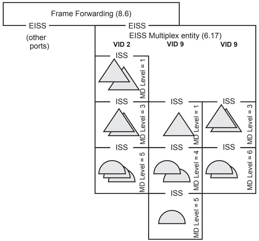
Figure J-1—Up MPs in a CFM Port
NOTE 1—Unlike normal Bridge Ports or a Management Port, multiple levels of MHFs can be present on a CFM Port for the same service instance, because they belong to different MAs on different Bridge Ports.
MPs on this CFM Port are distinguished by VID and by MD Level. However, those criteria are insufficient when Up MPs configured on different Bridge Ports are in the same MA, and thus in the same VID and at the same MD Level. There is no way of distinguishing, in that case, to which of those Up MPs a given CFM PDU is addressed. For the PDUs defined in this standard, this is not a problem.
Each MEP, even when multiple MEPs reside on a single CFM Port, has its own MEP Continuity Check Initiator state machine (20.12) and associated variables. Each MEP is responsible for transmitting its own CCMs, carrying information (e.g., the optional Sender ID TLV, 21.5.3) peculiar to its configured Bridge Port.
On the other hand, otherwise indistinguishable MEPs sharing a MAC address share a single LTR Transmitter state machine (20.50) and a single MEP Loopback Initiator transmit state machine (20.32), and their associated variables. The managed objects in 12.14.7.1.3 support this sharing.
When any CFM PDU arrives at the CFM Port, it is copied and delivered to each of the MPs that share the same MA. Each of these MPs responds to the CFM PDU separately and responds as if it resided in its configured Bridge Port. Since a multicast would be delivered to all of the MPs anyway, there is no harm in placing all of them in a single CFM Port, with a single MAC address.
Unicast CCMs, LTMs, LBRs, and LTRs present no issues. CCMs require no response. The LTMs all go to the Bridge’s single Linktrace Responder. Even when an LTM is multicast, only one LTR and/or forward LTM is produced, so delivering a unicast LTM to multiple MPs causes no additional problems. Since the MEPs sharing a single CFM Port also share a single MEP Loopback Initiator transmit state machine (20.32) and a single MEP Loopback Initiator receive state machine (20.34), and since they all share a single set of variables, particularly those related to the LTM Transaction Identifier fields in these PDUs, there is no confusion about which MEP the LBR or LTR is directed.
The remaining PDU type is the LBM. Consider what would happen if the MEPs and their associated MP Loopback Responders (19.2.10) resided on separate Bridge Ports, but all shared the same MAC address. Assuming that the Frame filtering entity had learned that MAC address, the LBM would be forwarded to exactly one of those MEPs, namely the one that, by chance, last happened to transmit a frame, thus causing the Learning Process (8.7) to associate the shared MAC address with that transmitter’s Bridge Port. Thus, exactly one LBR would be returned, not one per Bridge Port. The MEP receiving that LBR would not know from which MP the LBR was returned, because there is nothing in the LBR to indicate the identity of the responding MP. Therefore, only one response to a unicast LBM is returned from a CFM Port, no matter how many MPs on that LBM’s MA reside on the CFM Port.
On the other hand, a multicast LBM could cause any number of Up MPs configured in the same MA, but on different Bridge Ports in a single Bridge, to respond. Thus, a high-speed stream of multicast LBMs could impose an arbitrarily large burden upon a single CFM Port that is supporting a large number of Bridge Ports’ MPs, if each MP responded to that LBM. Therefore, among a set of MPs for a single MA that all share the same MAC address (i.e., reside on the same CFM Port), one or more, but not all, of their MP Loopback Responders (19.2.10) can be disabled by not configuring any group MAC address for them to recognize. This configuration is accomplished automatically by a Bridge that utilizes CFM Ports and is not controlled by any managed object.
The externally visible behaviors that can be discerned from outside a Bridge that uses the Shared MP address model are
a) An external MEP can regularly receive CFM PDUs other than LTRs, from two different MPs in the same MA that have the same source_address.
b) A multicast LBM can regularly receive only one reply from among a set of MPs that normally all respond to unicast LBMs, but all with the same source_address, without implying the presence of an intermittent network failure.
c) A system administrator can see unexpected advances in a MEP’s managed objects that count LBMs and LBRs, apparently due to activity on another MEP.
d) If conceptual rows in the Interface MIB module of IETF RFC 2863 are instantiated for individual MPs, the packet and frame counts of those interfaces count both CFM PDUs and ordinary data frames passing through the Active and Passive SAPs, and thus can indicate whether an MP is instantiated on the Bridge Port on which it is configured, or on a separate CFM Port through which no ordinary data frames pass.
NOTE 2—None of these behaviors is impossible for a Bridge using the Individual MP address model; MAC addresses can change faster than CCMs time out, momentary congestion can cause frame loss, multiple administrators can access different MEPs’ managed objects, and ordinary data frames can be absent. It is only the frequency of these behaviors that distinguishes the Individual MP address model from the Shared MP address model.
Annex K
(informative)
TPMR use cases
This material is intended to assist the reader of this standard in putting the operation of a TPMR in context with the operation of Bridged Networks as a whole, by illustrating some of the uses of a TPMR in conjunction with other types of Bridge. The set of cases is not, and is not intended to be, exhaustive in terms of all of the possible usage scenarios.
K.1 Use case 1—TPMR as User to Network Interface (UNI) demarcation device
Figure K-1 illustrates a use case where the TPMR performs the function of a UNI demarcation device between an customer network and a provider network. In this illustration, the user link between the customer Bridge and the TPMR, and the extension link between the TPMR and the provider Bridge, are both assumed to be IEEE 802.3 links, although, with the exception of the use of IEEE 802.3 EFM OAM on the extension link, these links could in principle be provided by use of any IEEE 802 LAN technology.
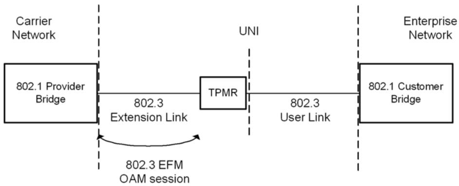
Figure K-1—TPMR as UNI demarcation device
The use of EFM OAM on the extension link allows the service provider to
a) Put the TPMR into an intrusive loopback for out-of-service testing.
b) Query the IEEE 802.3 MIB in the TPMR.
c) Be notified of critical events (Link Fault, Dying Gasp, Critical Event).
d) Be notified of link performance events (Errored Symbol Period event, Errored Frame event, Errored Frame Period event, Errored Frame Seconds Summary event).
The potential exists with EFM OAM (on the extension link) to make use of extensions, via organizationspecific OAMPDUs, to manage the Port of the TPMR that faces the user link.
Alternatively, the TPMR might be managed using SNMP over UDP/IP either in-band on the IEEE 802.3 extension link or out-of-band through separate management connector on the TPMR.
K.2 Use case 2—TPMRs with aggregated links
Figure K-2 illustrates a use case where two TPMRs are used within paired extension/user links that are aggregated at their endpoints (the Bridges). The TPMRs are transparent to the operation of the IEEE 802.1AX Link Aggregation Control Protocol (LACP), because the Provider Bridge and Customer Bridge are configured to use the “Nearest non-TPMR Bridge group address” as the destination address for LACP; from the point of view of Link Aggregation, each paired extension link and user link, with the TPMR joining them together, appears to be a single IEEE 802.3 LAN.
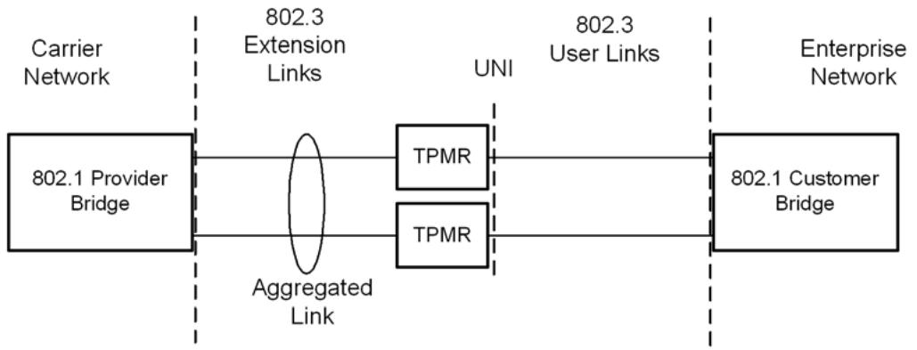
Figure K-2—TPMRs with aggregated links
The TPMRs would be managed separately, via EFM OAM, as in use case 1 (K.1). It should be noted that the use of SNMP to manage the TPMRs in this scenario is problematic, as the aggregated link appears to the higher layers to be a single link, but individual conversations are allocated by the frame distributor in the aggregator to the links in the aggregation in a nondeterministic manner.
K.3 Use case 3—Multiple TPMRs
Figure K-3 shows a variant of use case 1 (K.1) where two extension links and a user link are used, interconnected using two TPMRs.
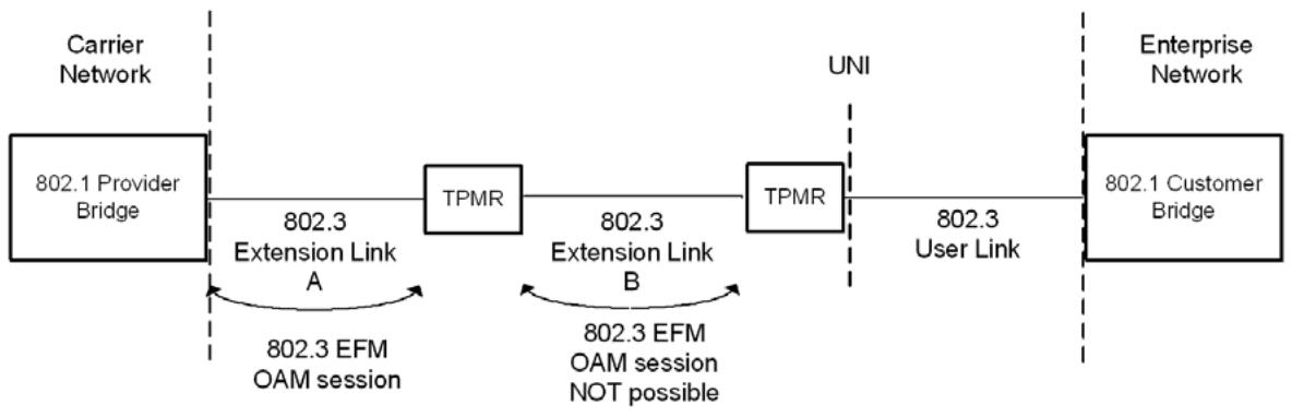
Figure K-3—Multiple TPMRs
Some commercial TPMRs used as demarcation devices power up in EFM OAM Passive mode, waiting to hear from the Active mode master device at the edge of the provider network. A passive-to-passive EFM OAM session, as would occur on extension link B, would never activate, making it impossible to manage the customer-facing TPMR by this means, unless significant changes were made to the capabilities of EFM OAM to allow some kind of relay capability. On the other hand, by using SNMP as the management protocol, this problem would be avoided.
K.4 Special cases
Figure K-4 (new connectivity) and Figure K-6 (connectivity failure) represent the target cases for the MAC status propagation design.
Figure K-4 shows recovery of the individual LAN at one end of at TPMR chain. The result is to “blip” the MAC_Operational status at the other end of the chain, delaying availability of the recovered link by slightly more than $\mathrm { T _ { w } + T _ { d } } .$ The figure also shows a possible effect of timing relationships between $\mathrm { T _ { r } }$ and $\mathrm { T _ { d } } ,$ as the initiator of the change retries its Add message transmission just as the TPMR at the other end of the chain returns a confirm. The crossing of messages shown is unlikely, as the time sequence diagrams overemphasize the delay experienced by the Add and Confirm messages, but the effect is benign in any case.
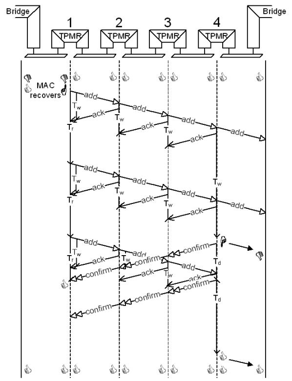
Figure K-4—Recovery at the end of a chain
If the LAN between the end system and the first TPMR in the chain (TPMR 1) had failed instead of recovering, the rest of Figure K-4 would have looked the same, with the exception of the final state of that first LAN. The net effect of the status notification protocol is to transfer the change in MAC_Operational to the other end of the chain so that both ends see the transition. For best effects the transfer should complete in a short enough time so that the end system protocols at the initiating end of the link are still executing their initial state.
Figure K-5 shows what happens if both ends of the link come up at the same time, the net effect is simply to delay the simultaneous start.
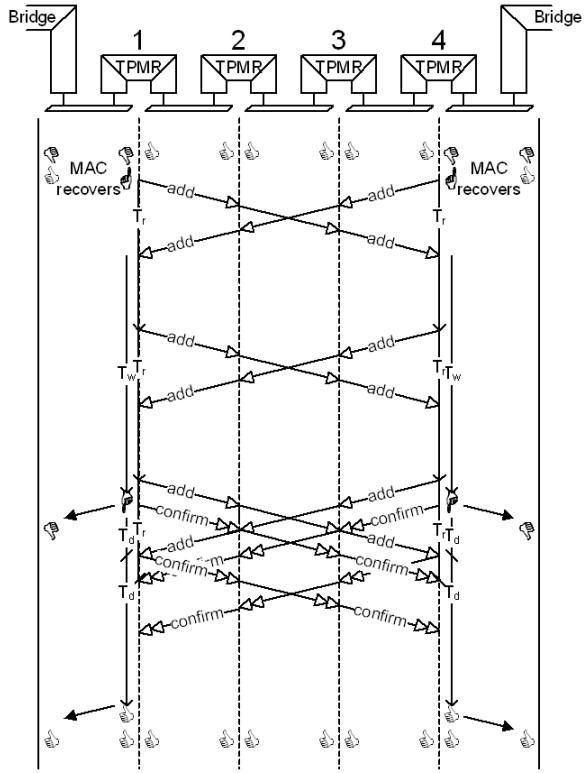
Figure K-5—Near simultaneous recoveries
Figure K-6 shows simultaneous transitions of one LAN in the chain to OperUp and the other to OperDown, and illustrates a number of points about how the protocol or protocols do or should operate.
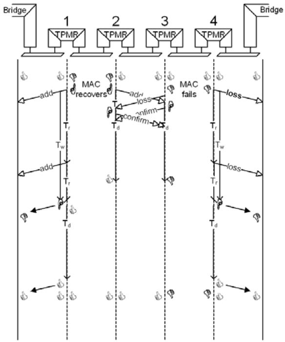
Figure K-6—Near simultaneous failure and recovery
First, signaling of addition or loss can be somewhat arbitrary and depend on the relative timing of transitions on separate individual LANs. The same final connectivity can be represented by a loss followed by an addition, or an addition followed by a loss. If the implied resulting state is to mean anything then the information “connected as far as,” or “connected to and beyond” also needs to be communicated. However, while this is a candidate for inclusion in any new protocol, support by existing protocols is unlikely. However, this clause persists with distinguishing Add and Loss messages, and their confirmations, because that ensures that closely spaced transitions, which might otherwise disguise unusual loss of higher layer protocol messages, are not missed by the systems connected to the TPMR chain. Figure K-7 shows a loss followed by recovery of the same LAN.
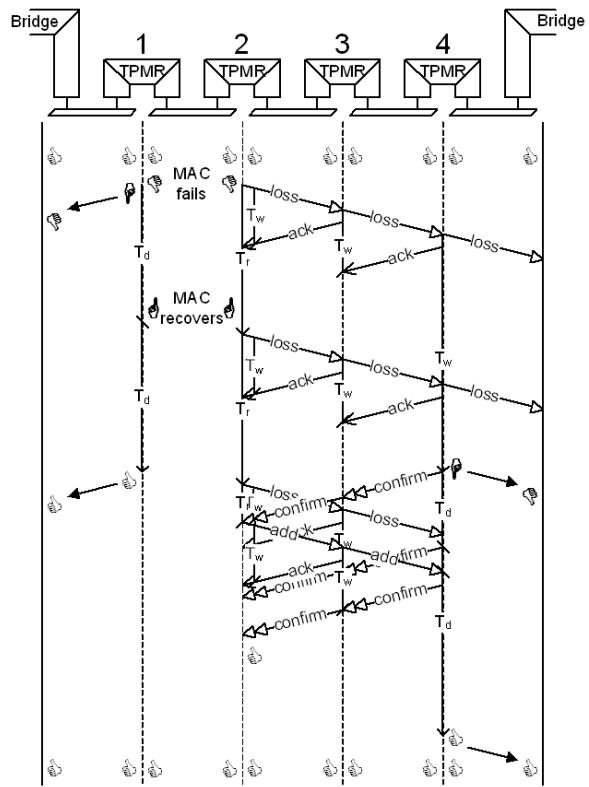
Figure K-7—Loss with quick recovery
Second, no message is sent across the LAN between TPMRs 1 and 2 when the MAC is OperDown from the protocol client’s point of view. That allows support of the protocol to be architected such that a message that signals “add(ition)” or “loss” is forwarded through the normal bridged path so its speed of propagation does not depend on scheduling or notifying a status propagation process in each TPMR. Also, users have a free choice about what additional functionality can reside between the entities responsible for status propagation and the “real” MAC.
One last common case of simultaneous transitions is what happens when the two ports of a TPMR power up or are enabled at the same time. Each tries to send a link notification through the other, and each link notification is discarded as the Port is not yet available (mssOperUp FALSE). The result is to “blip” each LAN. The ends of the TPMR chain see an Add Loss Add sequence, if they are protocol capable, and a blip in MAC_Operational otherwise. $\mathrm { I f T } _ { \mathrm { w } }$ is less than $\mathrm { T _ { d } } ,$ this will be a single blip.
Annex L
(informative)
Operation of the credit-based shaper algorithm
This annex contains a more detailed analysis of the way the credit-based shaper algorithm (8.6.8.2) operates, and how its operation affects the performance of the network, from the point of view of traffic that uses a credit-based shaped queue, and also from the point of view of other queues associated with the Port.
L.1 Overview of credit-based shaper operation
The credit-based shaper algorithm has a single externally determined parameter, idleSlope (see 8.6.8.2), that determines the maximum fraction of the portTransmitRate that is available to the queue associated with a traffic class (bandwidthFraction), as follows in Equation (L-1):
$$
\text { bandwidthFraction } = \text { idleSlope/portTransmitRate } \tag {L-1}
$$
where portTransmitRate is the maximum transmit data rate that the port supporting the outbound queue is able to deliver. The detailed derivation of Equation (L-1) can be seen in Equation (L-5) through Equation (L-8).
If a traffic class supported by the credit-based shaper algorithm uses less than the bandwidth allocated to it, then the unused bandwidth can be used by other traffic classes, in accordance with the relative priorities of the traffic classes and the transmission selection algorithms that are associated with them.
NOTE 1—It is a natural consequence of the way transmission selection operates that if a given traffic class does not have a frame available for transmission, then a lower priority traffic class that does have a frame available for transmission is able to transmit. Hence, if a given traffic class that uses the credit-based shaper algorithm has been allocated X% of the available bandwidth on a Port, but only uses (X-Y)%, then the unused portion of its allocation (Y%) is available for other traffic classes to use if they are in a position to do so. Whether this unused bandwidth can be used use by a traffic class depends upon the transmission selection algorithm that is associated with it. For example, a traffic class that has been allocated a specific bandwidth, such as one that uses the credit-based shaper algorithm, would be unable to use any bandwidth allocation not used by a higher priority traffic class, as that would result in it exceeding its bandwidth allocation; however, a traffic class that uses the strict priority algorithm, which is not associated with a bandwidth allocation, would be able to use bandwidth allocated to, but not used by, a higher priority traffic class.
The idleSlope parameter, in conjunction with the size of the frames that are being transmitted using the queue, and the maximum time delay that a queue can experience before it is able to transmit a queued frame, places an upper bound on the burst size that can be transmitted from queues that use the algorithm.
In order to describe the operation of the algorithm, it is useful to define the following values, in addition to the formal parameters of the algorithm described in 8.6.8.2:
a) maxFrameSize. The maximum sized frame that can be transmitted through the Port for the traffic class concerned. This value can be determined by admission control algorithms, or can be simply a function of the transmission behavior of the traffic source. Either way, the value can be smaller than would be allowed by the normal operation of the underlying MAC Service.
b) hiCredit. The maximum value that can be accumulated in the credit parameter. This parameter is a function of the operation of the algorithm, and cannot be controlled by management.
c) loCredit. The minimum value that can be accumulated in the credit parameter. The value of loCredit is a function of the values of maxFrameSize, portTransmitRate, and sendSlope, as follows in Equation (L-2).
$$
l o C r e d i t = \text { maxFrameSize } \times (\text { sendSlope } / \text { portTransmitRate }) \tag {L-2}
$$
d) maxInterferenceSize. The maximum size, in bits, of any burst of traffic that can delay the transmission of a frame that is available for transmission for this traffic class. For the numerically highest traffic class, maxInterferenceSize is exactly equal to the maximum sized frame that can be transmitted through the Port (the maximum frame size supported by the underlying MAC). For all other traffic classes, the derivation of maxInterferenceSize becomes more complex, owing to the possibility that any higher traffic classes that support the credit-based shaper algorithm can delay the transmission of a frame. maxInterferenceSize must also account for any media access delay, such as the recovery time in Energy Efficient Ethernet. A detailed analysis can be found in L.3.1.1.
NOTE 2—The definition of maxInterferenceSize assumes that any traffic classes that support the shaper algorithm are numerically higher than any traffic classes that support the default strict priority algorithm (8.6.8.1). If this is not true, then the value of maxInterferenceSize is infinite, and the operation of the credit-based shaper algorithm cannot provide the bandwidth that has been reserved for it. A detailed analysis of how maxInterferenceSize can be determined for a given traffic class is contained in L.3.
The value of hiCredit is determined by the worst-case interfering traffic, as follows in Equation (L-3).
$$
h i C r e d i t = \text { maxInterferenceSize } \times (\text { idleSlope } / \text { portTransmitRate }) \tag {L-3}
$$
The value of hiCredit can therefore be considered as a “high water mark”; the operation of the algorithm is such that the value of the credit parameter will never exceed hiCredit.
The choice of value for idleSlope, and the calculated value of hiCredit, can be used to determine the maximum burst size that can be output from the queue, as follows in Equation (L-4).
$$
\text { maxBurstSize } = (\text { portTransmitRate } \times ((h i C r e d i t - l o C r e d i t) / (- s e n d S l o p e))) \tag {L-4}
$$
NOTE 3—There is an interrelationship between the maximum burst size and the buffer size available to the traffic class. There is no point in accumulating more credit than the traffic class can handle in queued frames, as the limiting factor is the discarding of frames when the queue overflows. This means that the amount of bandwidth that can be reserved on a given Port for a given traffic class depends upon the amount of buffering available to that traffic class. This in turn, combined with the port’s transmission rate, will determine the maximum value of idle slope that can be supported for that traffic class on that Port.
The operation of the credit-based shaper algorithm is illustrated in the examples shown in Figure L-1 through Figure L-3. In Figure L-1, a frame is queued at a time when the credit value is zero, and there is no conflicting traffic (there is no higher priority traffic awaiting transmission, and there is no frame being transmitted on the Port). The frame is immediately selected for transmission, and credit decreases at the rate of sendSlope as the transmission proceeds. Once the frame transmission is complete, credit increases back to zero at the rate of idleSlope, at which point, a further frame can be selected for transmission.
If a continuous stream of frames is made available to the shaper algorithm, i.e., there is always one frame queued awaiting transmission when the credit value reaches zero, then the fraction of the portTransmitRate that is available to the queue (bandwidthFraction) is equal to the fraction of time that frames are being transmitted from the queue. Assuming that credit decreases to value loCredit at the end of each frame transmission, then the following shows the detailed derivation of Equation (L-1):
$$
\text { bandwidthFraction } = (- \text { loCredit / sendSlope }) / [ (- \text { loCredit / sendSlope }) + (\text { loCredit / idleSlope }) ] \tag {L-5}
$$
$$
= (- 1 / \text { sendSlope }) / [ (1 / \text { idleSlope }) - (1 / \text { sendSlope }) ] \tag {L-6}
$$
$$
= (- \text { idleSlope }) / (\text { sendSlope } - \text { idleSlope }) \tag {L-7}
$$
$$
= \text { idleSlope } / \text { portTransmitRate } \tag {L-8}
$$
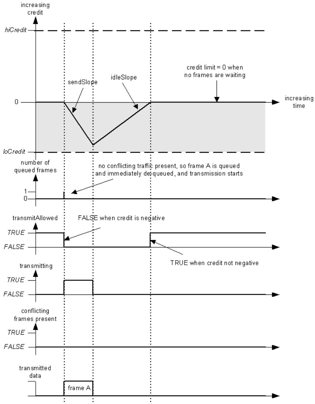
Figure L-1—Credit-based shaper operation—no conflicting traffic
This fraction of the bandwidth is available to the stream even in the presence of conflicting traffic, as illustrated in the following examples. In Figure L-2, a frame is queued at a time when the Port is transmitting conflicting traffic. The value of credit increases at the rate of idleSlope while the queued frame waits for the Port to become available. Transmission of the conflicting traffic completes before the value of credit is limited by hiCredit, and transmission of the queued frame starts. The value of credit starts to decrease at the rate of sendSlope; however, as the frame is not large enough to consume all of the available credit, and there are no further frames queued, credit is reduced to zero on completion of the transmission.
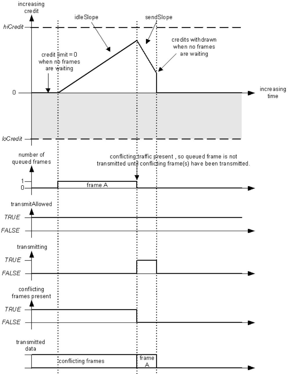
Figure L-2—Credit-based shaper operation–conflicting traffic
In Figure L-3, three frames are queued while the Port is transmitting conflicting traffic, and credit accumulates at the rate of idleSlope. Once the conflicting traffic has been transmitted, the first and second frames are transmitted back-to-back, because transmitting the first frame leaves credit 0. However, as transmitting the second frame causes credit to become negative, transmission of the third frame is delayed until credit returns to zero.
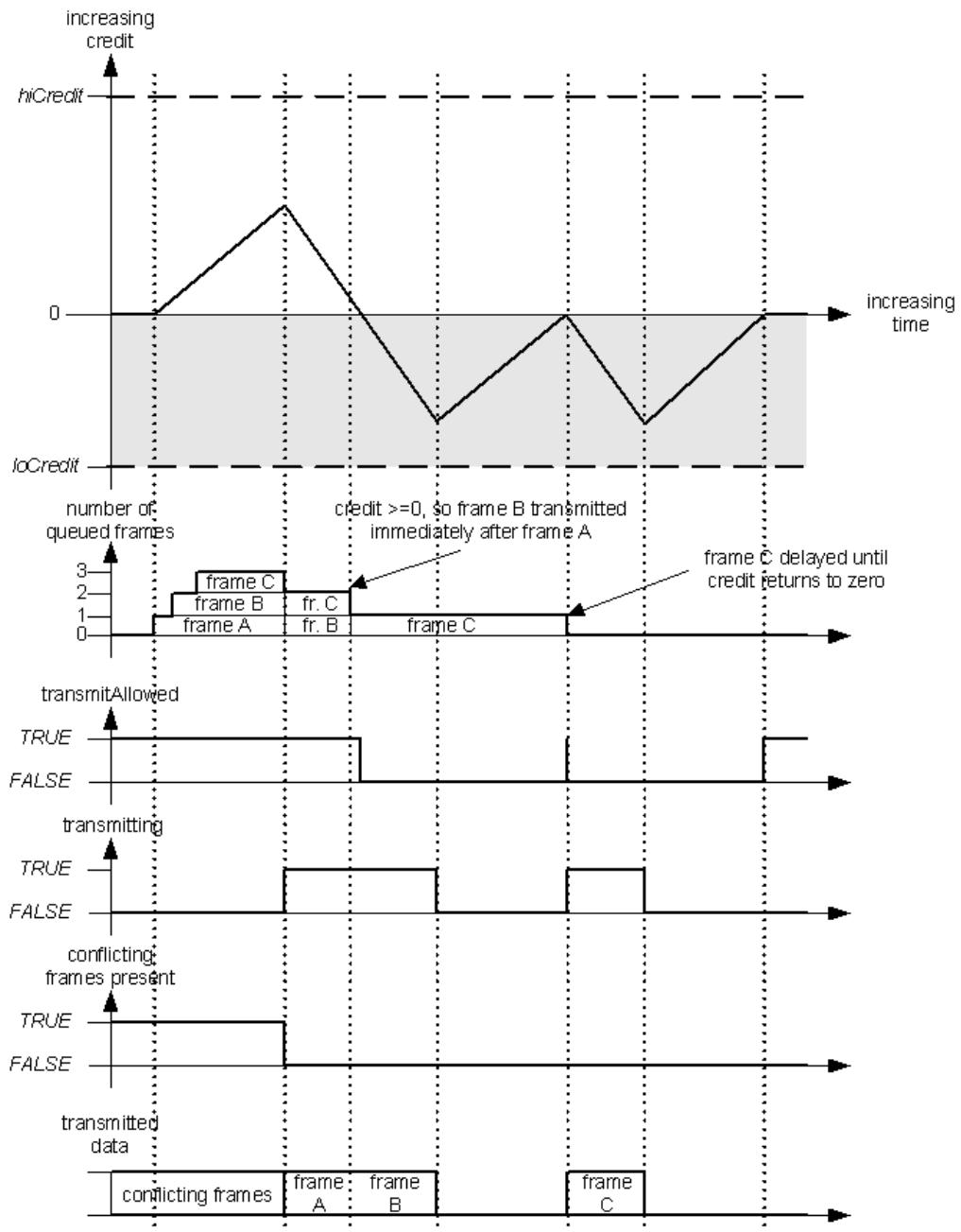
Figure L-3—Credit-based shaper operation—burst traffic
L.2 “Class measurement intervals” in Bridges
The “class measurement interval” defines acceptable Talker behavior with respect to per-stream transmission (see 34.6.1); however, it does not directly impact the operation of the credit-based shaper algorithm in Bridges.
The maximum fraction of the available bandwidth that a queue operating the credit-based shaper algorithm consumes is determined by idleSlope, as discussed in L.1; if idleSlope is 75% of the link transmission rate, then the algorithm gets a maximum of 75% of the link, averaged over some time period (the class measurement interval) at the Talker. For a Bridge, where transmission becomes bursty due to interfering transmission from other traffic classes, the minimum measurement interval that is meaningful (i.e., the minimum period over which it is still possible to observe that the 75% maximum bandwidth is not exceeded) is the time taken for the traffic class concerned to transmit a maximum sized burst, multiplied by 100/75. In the case of the 125 μs class measurement interval for SR class A traffic, on 100 Mbit/s Ethernet, and with 75% reservation, the approximate calculation is (ignoring interframe gaps)
a) The maximum interference size (maxInterferenceSize) is one maximum sized Ethernet frame, which is 2000 octets, or 16 000 bits, so hiCredit would be 75% of that, or 12 000 bits.
NOTE 1—Media access delays, such as those imposed by Energy Efficient Ethernet, could be more significant than the interference created by a maximum sized frame.
NOTE 2—The figure of 2000 octets is a maximum for Ethernet and therefore a worst case for an interfering frame; in a specific implementation, the maximum frame size that is used could be smaller. In implementations where the maximum frame size is known to be less than 2000, the smaller value could be used.
b) The maximum frame size for this traffic class is 75% of the number of bits that can be transmitted in 125 μs, so 75% of 12 500 bits in the case of a 100 Mbit/s LAN, or 9375 bits (including up to 500 or so possible “overhead” octets—used for, e.g.,Tag headers, physical layer overhead). As this is not an integral number of octets, this figure is rounded down to 9368. loCredit is 25% of that, or –2342.
c) The maximum burst size, for frames no greater than 9368 bits long, would occur if credit reached 12 000, then a series of frames were transmitted that exactly took credit to 0, followed by a final 9368 bit frame that would take credit down to –2342. This maximum burst is therefore calculated as (12 000 + 2342) • (portTransmitRate/(-sendSlope)) or 57 368 bits.
d) The minimum measurement interval over which one can expect to be able to measure the bandwidth utilization for SR class A, and observe that it does not exceed its 75% allocation, is therefore 57 368 bit times multiplied by 100/75, which is 76 491 bit times, rounded up to the nearest integer, or 764.91 μs.
NOTE 3—The maximum sized burst will be preceded by a maxInterferenceSize event, and at the end of the burst, credit will have been reduced to –2342; it will therefore take 2342/idleSlope seconds, or nearly 3123 bit times, for credit to return to zero, and for SR Class A to be allowed to transmit again. In addition, the actual utilization for SR Class A is 57368/(57368+16000+ (2342/0.75)) = 75%.
For the SR class B traffic, all that really changes is the potential size of any interference, which increases from the SR class A maxInterferenceSize to the maximum burst size for SR class A plus the class A maxInterferenceSize.
So, the smallest possible measurement interval over which the ratio idleSlope/portTransmitRate will be seen to hold good is dependent on the maximum interference size for the SR class, the maximum frame size for the SR class, and the value of idleSlope.
L.3 Determining worst-case latency contribution and buffering requirements
From the point of view of the operation of AV Bridges, it is important to be able to assess the contribution that each Bridge makes to the worst-case latency that stream data frames can be subject to during their transmission along the path from Talker to Listener. Closely related to the latency contribution that a Bridge makes is the buffering requirement that is required in the Bridge in order for the delay not to result in frame discard; if a Bridge can potentially delay a frame of a given SR class for a given period of time, then it must be capable of buffering the worst-case number of frames of that same SR class that could be received for onward transmission on each Port. The following discussion looks at the factors that contribute to the delay that could be experienced by a frame as it passes through a Bridge, and how the delay can be accurately determined.
NOTE 1—This discussion is also useful to guide designers of Talker stations in determining the delay added by the Talker’s network interface.
The worst-case latency for a single hop from Bridge to Bridge, measured from arrival of the last bit at Port n of Bridge A to the arrival of the last bit at Port m of Bridge B, can be broken out into the following components:
a) Input queuing delay. (There are no input queues in the IEEE 802.1 architecture, but if present, the implementation must account for them.)
b) Interference delay (L.3.1).
c) Frame transmission delay. (The time taken to transmit one maximum frame at portTransmitRate.)
d) LAN propagation delay. (A variable delay that depends on the length of the LAN connection to the next Bridge; this is measurable using the mechanisms defined in IEEE Std 802.1AS [B7].)
e) Store-and-forward delay. This includes all other elements of forwarding delay that are a consequence of the internal processing of the Bridge, assuming that the input and output queues are empty, such as
1) The time needed to pass a frame from the input port to the output port, assuming empty queues.
2) The time delay between a frame being available for transmission on a Port and the Port being ready to transmit the frame.
NOTE 2—For example, in the case where the MAC/PHY has entered a power saving mode, there may be a delay incurred in switching the Port back to normal operation.
3) The difference, if any, in the delay incurred by a frame that bypasses an empty queue, vs. that incurred by a frame that must be enqueued.
4) The time added (subtracted) by the lengthening (shortening) of the frame due to addition (removal) of frame headers such as Q-tags or MACSec-tags.
5) The time needed to encrypt a MACSec frame.
In the remainder of this clause, the following abbreviations are used:
<table><tr><td><eq>M_{0}</eq></td><td>Maximum sized frame for non-SR classes</td></tr><tr><td><eq>M_{x}</eq></td><td>Maximum sized frame for SR class x</td></tr><tr><td><eq>R_{0}</eq></td><td>portTransmitRate</td></tr><tr><td><eq>R_{x}</eq></td><td>idleSlope for SR class x</td></tr><tr><td><eq>T_{xy}</eq></td><td>Time interval between events x and y</td></tr><tr><td><eq>W_{x}</eq></td><td>-sendSlope<eq>_{x}</eq></td></tr><tr><td>variable<eq>_{<x}</eq></td><td>The sum of the values of the named variable for all SR classes with a higher priority (and therefore earlier letter in the collating sequence) than x</td></tr></table>
<!-- merged from 802.1Q_2014_1801-1832.md -->
L.3.1 Interference delay
The interference delay for frame X can be broken out into the following components:
a) Queuing delay: The delay caused by the frame that was selected for transmission an arbitrarily small time before frame X became eligible for transmission selection, plus the delay caused by queued-up frames from all stream frames with higher priority than frame X’s class (i.e., the “maxBurstSize” for SR Classes with higher priority than X—see L.1). This is what is referred to as maxInterferenceSize in L.1. Queuing delay is analyzed in detail in L.3.1.1.
b) Fan-in delay: The delay caused by other frames in the same class as frame X that arrive at more-orless the same time from different input Ports. Fan-in delay is analyzed in detail in L.3.1.2.
c) Permanent delay: The delay caused by frames that reside in a buffer for a long time, relative to the output queuing delay, because of the history of activity in the network. Permanent delay is analyzed in detail in L.3.1.3.
L.3.1.1 Queuing delay
The queuing delay for frame X can be broken out into the following components:
a) The delay, maxInterferenceTime, before a frame X queued for an SR class, and that is eligible for transmission, can actually be transmitted. This delay is experienced when a frame, of any priority, is selected for transmission an arbitrarily small time before frame X became eligible for transmission; it is also experienced in LAN media, such as Ethernet, where there can be a low energy consumption mode that is entered under idle conditions, and where there is a significant delay, mediumAccessDelay, before the LAN returns to normal operation and is able to transmit. The value of maxInterferenceTime is therefore equal to whichever is the greater of the following:
1) The time taken to transmit the maximum frame size supported by the medium, i.e., ma $c F r a m e S i z e _ { ( m ) } \mathrm { ~ / ~ }$ portTransmitRate.
2) The mediumAccessDelay for the medium.
b) The delay caused by any queued-up frames associated with the next higher priority SR class than frame X’s SR class (i.e., maxBurstSize for the next higher priority SR class), if frame X does not belong to the highest SR class.
For SR class A, only the first of these components applies, as there is no higher SR class.
Suppose that the queue for SR class A is full, and it has accumulated the maximum amount of credit (hiCredit). Because SR class A frames have priority over all other traffic (even BPDUs), hiCredit for SR class A is merely the credit accumulated during the maxInterferenceTime required to transmit a lowerpriority frame. Until that accumulated credit is exhausted, SR class B $\left( \mathrm { C } , \mathrm { D } , \ldots \right)$ frames cannot be transmitted.
If SR class A were permitted to use 100% of the LAN bandwidth, then the SR class A queue would never catch up, because it would use credit as fast as it was gained, and there would never be a chance for any other traffic class to transmit a frame. If SR class A were permitted to use 99% of the LAN bandwidth, then SR class A can transmit back-to-back frames and the accumulated credit would be drained at 1% of the LAN bandwidth until it goes negative; at that point, SR class A cannot transmit further frames until its credit returns to a non-negative value, which ensures that at least 1% of the bandwidth is available to other traffic classes.
NOTE—In general, if SR Class A is permitted to use X% of the bandwidth, then only (100-X)% remains available for use by lower priority traffic classes. In practice, as 75% is the default value for the highest percentage of portTransmitRate that can be used by all SR classes, there is always at least 25% of portTransmitRate available for use by the non-SR traffic classes.
Figure L-4 illustrates this burst transmission behavior, and the effect of maxInterferenceTime on the latency of SR class frames. At point a on the time line, the queues for SR classes A and B are empty, and a maximum sized frame $( \mathrm { M } _ { 0 }$ bits long) belonging to a non-SR traffic class starts transmission. An instant later, SR class A and B frames arrive that are all of the maximum size that the classes are currently experiencing $( \mathrm { { M } _ { A } }$ and $\mathrm { { { M } _ { B } } }$ bits long, respectively); however, as there is a frame already being transmitted, they are queued. At point b, transmission of the non-SR class frame completes, and the first of a burst of four SR class A frames are transmitted. By point d, SR class A’s credit has been taken negative by the transmission of the last of its burst of frames, and therefore no further SR Class A frames can be transmitted until its credit is no longer negative; this allows SR Class B to transmit a frame. What happens at the end of the class B frame will depend on what frames are queued waiting for transmission, and whether the credit available to either of the SR classes is non-negative.
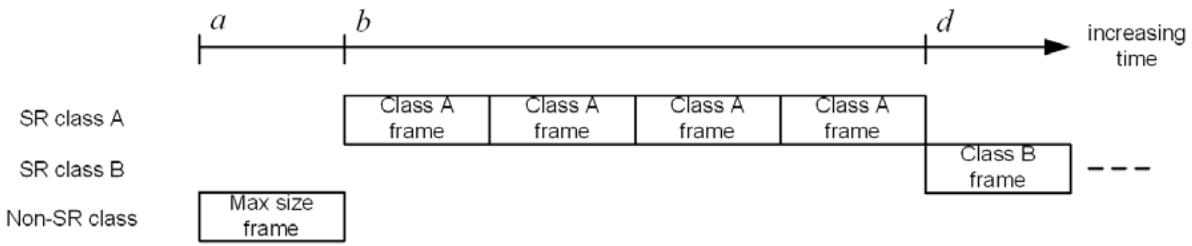
Figure L-4—Interference and latency
The queuing delay experienced by the first SR Class A frame is therefore the time interval between a and b, $\mathrm { T _ { a b } } .$ If $\mathrm { R } _ { 0 }$ is the transmission rate (portTransmitRate), then
$$
\mathrm{T} _ {\mathrm{ab}} = \mathrm{M} _ {0} / \mathrm{R} _ {0} = \text { maxInterferenceTime } \tag {L-9}
$$
Figure L-5 shows how credit changes for SR Class A during this sequence.
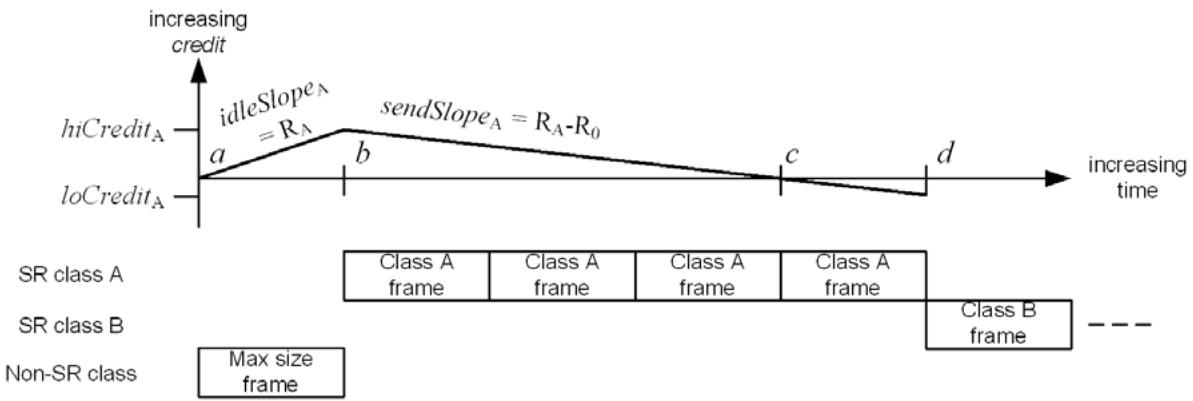
Figure L-5—Burst behavior and credit
$\mathrm { R _ { A } }$ is the reserved data rate for SR Class A (which is the idleSlope for class A), $\mathrm { R _ { B } }$ is the reserved data rate for SR Class B, and so on. The value of $c r e d i t _ { \mathrm { A } }$ accumulates up to $h i C r e d i t _ { \mathrm { A } }$ during the transmission of the maximum sized non-SR frame so that
$$
h i C r e d i t _ {\mathrm{A}} = \mathrm{R} _ {\mathrm{A}} \times \mathrm{M} _ {0} / \mathrm{R} _ {0} = \text { idleSlope } _ {\mathrm{A}} \times \text { maxInterferenceTime } \tag {L-10}
$$
credit is drained during the transmission of the SR Class A frames, at the rate $s e n d S l o p e _ { \mathrm { A } } .$ as follows:
$$
\text { sendSlope } _ {\mathrm{A}} = \left(\mathrm{R} _ {\mathrm{A}} - \mathrm{R} _ {0}\right) \tag {L-11}
$$
credit reaches zero at point c in Figure L-5, which, for the purposes of this discussion, is assumed to happen exactly at the point where transmission of the third class A frame finishes. Since a frame can be transmitted when $c r e d i t = 0 .$ Class A’s credits continue to drain to the following value:
$$
\text { loCredit } _ {A} = \left(\mathrm{R} _ {\mathrm{A}} - \mathrm{R} _ {0}\right) \times \mathrm{M} _ {\mathrm{A}} / \mathrm{R} _ {0} \tag {L-12}
$$
during the transmission of the fourth class A frame $( \mathrm { { M } _ { A } }$ bits long, transmitted in time $\mathrm { M _ { A } / R _ { 0 } } )$ . At point $d ,$ transmission of the fourth frame completes; as $c r e d i t _ { A }$ is now negative, no more class A frames can be transmitted, and transmission of a class B frame starts.
So, for class A, the maximum burst size is equal to the transmission rate, $\mathrm { R } _ { 0 } ,$ multiplied by the time interval between points b and d in Figure L-5:
$$
\max \text { Class A burst size } = R _ {0} \times (- (h i C r e d i t _ {A} - l o C r e d i t _ {A}) / s e n d S l o p e _ {A}) \tag {L-13}
$$
Substituting $h i C r e d i t _ { A } ,$ $\mathit { s e n d S l o p e } _ { A } ,$ and $l o C r e d i t _ { A }$ from Equation (L-10), Equation (L-11), and Equation (L-12), respectively, results in the following:
$$
\max \text { Class A burst size } = R _ {0} \times \left(- \left(R _ {\mathrm{A}} \times M _ {0} / R _ {0} - \left(R _ {\mathrm{A}} - R _ {0}\right) \times M _ {\mathrm{A}} / R _ {0}\right) / \left(R _ {\mathrm{A}} - R _ {0}\right)\right) \tag {L-14}
$$
$$
= \mathrm{R} _ {0} \times \left(\mathrm{R} _ {\mathrm{A}} \times \mathrm{M} _ {0} / \mathrm{R} _ {0}\right) / \left(\mathrm{R} _ {0} - \mathrm{R} _ {\mathrm{A}}\right) + \mathrm{M} _ {\mathrm{A}} / \mathrm{R} _ {0} \tag {L-15}
$$
$$
= \left(\mathrm{R} _ {\mathrm{A}} \times \mathrm{M} _ {0}\right) / \left(\mathrm{R} _ {0} - \mathrm{R} _ {\mathrm{A}}\right) + \mathrm{M} _ {\mathrm{A}} \tag {L-16}
$$
The queuing delay experienced by SR class B is the time interval between a and d in Figure $\mathrm { L } { - } 5 , \mathrm { T _ { a d } } .$
$$
\mathrm{T} _ {\mathrm{ad}} = \mathrm{T} _ {\mathrm{ab}} + \mathrm{T} _ {\mathrm{bc}} + \mathrm{T} _ {\mathrm{cd}} \tag {L-17}
$$
$$
= \mathrm{M} _ {0} / \mathrm{R} _ {0} + h i C r e d i t _ {A} / s e n d S l o p e _ {A} + \mathrm{M} _ {\mathrm{A}} / \mathrm{R} _ {0} \tag {L-18}
$$
$$
= \mathrm{M} _ {0} / \mathrm{R} _ {0} + \left(\mathrm{R} _ {\mathrm{A}} \times \mathrm{M} _ {0} / \mathrm{R} _ {0}\right) / \left(\mathrm{R} _ {0} - \mathrm{R} _ {\mathrm{A}}\right) + \mathrm{M} _ {\mathrm{A}} / \mathrm{R} _ {0} \tag {L-19}
$$
$$
= \mathrm{M} _ {0} / \left(\mathrm{R} _ {0} - \mathrm{R} _ {\mathrm{A}}\right) + \mathrm{M} _ {\mathrm{A}} / \mathrm{R} _ {0} \tag {L-20}
$$
This can be generalized to calculate the queuing delay experienced by any SR class, X, by using the sum of the credits available to all higher priority SR classes. In the following, the subscript $^ { \circ } < \mathrm { X } ^ { \circ }$ is used to indicate the sum of the values for all SR classes with higher priority (and therefore, earlier letters in the collating sequence) than X.
The credit acquisition rate $i d l e S l o p e _ { < X }$ for SR classes A through X-1 is the sum of the data rates for all higher priority classes so that
$$
i d l e S l o p e _ {< X} = \sum_ {\mathrm{K} < \mathrm{X}} \mathrm{R} _ {\mathrm{K}} \tag {L-21}
$$
This is just the sum of the $i d l e S l o p e _ { K }$ values for the higher classes. However, the combined classes accumulate credits only until the single interfering non-SR interfering frame stops transmitting, and then the credits start decreasing linearly. So, the upper limit for the combined credits is not the sum of the individual Class’s credits; it is the number of bits divided by the slope, or
$$
h i C r e d i t _ {< X} = \left(\sum_ {\mathrm{K} < \mathrm{X}} \mathrm{R} _ {\mathrm{K}}\right) \times \mathrm{M} _ {0} / \mathrm{R} _ {0} \tag {L-22}
$$
Similarly, the combined sendSlope<X is
$$
\text { sendSlope } _ {< X} = - \left(\mathrm{R} _ {0} - \sum_ {\mathrm{K} < \mathrm{X}} \mathrm{R} _ {\mathrm{K}}\right) \tag {L-23}
$$
These combined rates hold true until some class’s buffer empties and its credits are forced to 0. In the worstcase scenarios examined here, this does not happen.
Defining
$$
\mathrm{W} _ {< \mathrm{X}} = - \text { sendSlope } _ {< X} = \mathrm{R} _ {0} - \sum_ {\mathrm{K} < \mathrm{X}} \mathrm{R} _ {\mathrm{K}} \tag {L-24}
$$
leads to
$$
\text { sendSlope } _ {< X} = - \mathrm{W} _ {< X} \tag {L-25}
$$
and
$$
h i C r e d i t _ {< X} = \left(\mathrm{R} _ {0} - \mathrm{W} _ {< \mathrm{X}}\right) \times \mathrm{M} _ {0} / \mathrm{R} _ {0} \tag {L-26}
$$
For all combined classes, $\mathrm { T _ { a b } }$ is the same as for SR class A, the time for the non-SR frame to transmit
$$
\mathrm{T} _ {\mathrm{ab}} = \mathrm{M} _ {0} / \mathrm{R} _ {0} \tag {L-27}
$$
The combined classes A through X-1 drain from $h i C r e d i t _ { < X }$ to 0 in time $h i C r e d i t _ { < X } / \mathrm { W _ { < X } }$ so that
$$
\mathrm{T} _ {\mathrm{bc}} = \left(\left(\mathrm{R} _ {0} - \mathrm{W} _ {< \mathrm{X}}\right) \times \mathrm{M} _ {0} / \mathrm{R} _ {0}\right) / \mathrm{W} _ {< \mathrm{X}} \tag {L-28}
$$
The worst-case value of $l o C r e d i t { _ { < X } }$ for the combined <X classes is not the sum $\scriptstyle \sum _ { \mathrm { K < X } }$ loCreditK as this would overestimate the worst case. Only one of the <X classes can be transmitting a frame at a given time, so the end of the burst for the ${ < } \mathrm { X }$ classes occurs when one of the ${ < } \mathrm { X }$ classes, Q say, starts transmitting a frame at a point where all the other ${ < } \mathrm { X }$ classes have negative credit, and their credit is therefore rising. If, by the time $\mathrm { Q } \mathrm { \ ' } \mathrm { s }$ frame transmission finishes, the other ${ < } \mathrm { X }$ classes still have negative credit, then Q’s frame is the last frame of the ${ < } \mathrm { X }$ burst; but at that point, all the other <X classes must, by definition, have more credit than their respective loCredit values $( \mathrm { i . e . , }$ for these other classes, credit > loCredit) because even if they were at their respective loCredit values when Q started transmitting, they have been gaining credit during the transmission of $\mathrm { Q } \mathrm { \ ' { s } }$ frame.
It is also not possible to decide that $l o C r e d i t { _ { < X } }$ is simply the time needed to transmit one copy of each Class’s maximum-length frame; for some classes it could be possible transmit more than a single last frame after the total credits = 0, even if all Classes’ credits reach 0 simultaneously. For example, classes A and B reach $c r e d i t = 0$ at the same time; A transmits a frame, then B transmits a frame. By the end of the B frame, A’s credit has returned to zero, and so A can transmit a further “last” frame.
Some class must transmit the last frame, and for it to be the worst case, that last frame is a maximum length frame. If it were not, then either
c) Extending it to the maximum length still leaves the other classes at negative credit; or
d) Extending it to the maximum length leaves one or more other class with 0 or positive credit, in which case they will transmit more frames.
$\mathrm { S o } ,$ for class Q to be the class that transmits the last frame of the <X burst, the following condition must be true for all other <X classes, P:
$$
\mathrm{M} _ {\mathrm{q}} \times \mathrm{R} _ {\mathrm{P}} > (\mathrm{R} _ {0} - \mathrm{R} _ {\mathrm{P}}) \times \mathrm{M} _ {\mathrm{p}} \tag {L-29}
$$
Equation (L-29) follows from the fact that the increase in credits of class P during the transmission of $\mathrm { M } _ { \mathrm { q } } ,$ , which is equal to $( \mathrm { M } _ { \mathrm { q } } / \mathrm { R } _ { 0 } ) \times \mathrm { R } _ { \mathrm { p } }$ is greater than the absolute value of the loCredit of P, which is equal to $( \mathrm { R } _ { 0 } ^ { \cdot } - \mathrm { R } _ { \mathrm { P } } ) \times \mathrm { M } _ { \mathrm { p } } . \ \mathrm { S } \mathrm { o }$ ,
$$
\left(\mathrm{M} _ {\mathrm{q}} / \mathrm{R} _ {0}\right) \times \mathrm{R} _ {\mathrm{P}} > \left(\mathrm{R} _ {0} - \mathrm{R} _ {\mathrm{P}}\right) \times \mathrm{M} _ {\mathrm{p}} / \mathrm{R} _ {0} \tag {L-30}
$$
This statement is true because the other classes P must have low enough credit that their credit cannot climb above 0 during the transmission of $\mathrm { M } _ { \mathrm { q } }$ .
The very lowest that $c r e d i t _ { \mathrm { < X } }$ might reach for three SR classes, Q, P, and S is shown in Equation (L-31).
$$
l o C r e d i t _ {< \mathrm{X}} \geq l o C r e d i t _ {\mathrm{Q}} + l o C r e d i t _ {\mathrm{P}} + l o C r e d i t _ {\mathrm{S}} + \mathrm{R} _ {\mathrm{S}} \times \mathrm{M} _ {\mathrm{q}} / \mathrm{R} _ {0} + \mathrm{R} _ {\mathrm{P}} \times \mathrm{M} _ {\mathrm{q}} / \mathrm{R} _ {0} \tag {L-31}
$$
However, even this is pessimistic, as it assumes that more than one class can be at their loCredit at the same time, which is not the case. What this shows, however, is that if $\mathrm { R } _ { \mathrm { K } }$ is small for all $\operatorname { K } { < } \operatorname { X } \left( \operatorname { i . e . , \operatorname { R } _ { K } } { < } { < } \operatorname { R } _ { 0 } \right)$ , then the $\mathrm { R _ { K } } \times \mathrm { M _ { q } } / \mathrm { R _ { 0 } }$ terms all approach zero, and therefore $l o C r e d i t { _ { < X } }$ approaches the sum $\scriptstyle \sum _ { \mathrm { K < X } } l o C r e d i t _ { \mathrm { K } } . \mathrm { S o } .$ ,
$$
\text { loCredit } _ {< \mathrm{X}} = \sum_ {\mathrm{K} < \mathrm{X}} \text { loCredit } _ {\mathrm{K}} \tag {L-32}
$$
$$
= \sum_ {K < X} (R _ {K} - R _ {0}) \times M _ {K} / R _ {0} \tag {L-33}
$$
But in this worst case, $\mathrm { R _ { K } } { < } < \mathrm { R _ { 0 } } ;$ therefore,
$$
\text { loCredit } _ {< \mathrm{X}} = \sum_ {\mathrm{K} < \mathrm{X}} (- \mathrm{M} _ {\mathrm{K}}) \tag {L-34}
$$
Putting together these various components, the queuing delay for SR Class X, qDelayX, is as follows:
$$
\mathrm{qDelay} _ {\mathrm{X}} = \mathrm{M} _ {0} / \mathrm{R} _ {0} + (h i C r e d i t _ {< \mathrm{X}} - l o C r e d i t _ {< \mathrm{X}}) / | s e n d S l o p e _ {< \mathrm{X}} | \tag {L-35}
$$
$$
= \mathrm{M} _ {0} / \mathrm{R} _ {0} + \left(\left(\mathrm{R} _ {0} - \mathrm{W} _ {< \mathrm{X}}\right) \times \mathrm{M} _ {0} / \mathrm{R} _ {0} + \sum_ {\mathrm{K} < \mathrm{X}} \mathrm{M} _ {\mathrm{K}}\right) / \mathrm{W} _ {< \mathrm{X}} \tag {L-36}
$$
$$
\mathrm{qDelay} _ {\mathrm{X}} = \left(\mathrm{M} _ {0} + \sum_ {\mathrm{K} < \mathrm{X}} \mathrm{M} _ {\mathrm{K}}\right) / \mathrm{W} _ {< \mathrm{X}} \tag {L-37}
$$
For SR class A, this equation reduces to Equation (L-38):
$$
\mathrm{qDelay} _ {\mathrm{A}} = \mathrm{M} _ {0} / \mathrm{W} _ {< \mathrm{A}} \tag {L-38}
$$
As there is not a $^ { \circ } < \mathbf { A } ^ { \circ }$ class, A being the highest priority class, $\mathrm { W _ { < A } }$ is simply $\mathrm { R } _ { 0 } ,$ so this reduces to Equation (L-39):
$$
\mathrm{qDelay} _ {\mathrm{A}} = \mathrm{M} _ {0} / \mathrm{R} _ {0} \tag {L-39}
$$
This agrees with the earlier discussion in L.1.
For SR class B, the equation reduces to Equation (L-40):
$$
\mathrm{qDelay} _ {\mathrm{B}} = \left(\mathrm{M} _ {0} + \mathrm{M} _ {\mathrm{A}}\right) / \mathrm{W} _ {\mathrm{A}} \tag {L-40}
$$
As $\mathrm { W _ { A } }$ is $- s e n d S l o p e _ { A } .$ , which is just $\mathrm { R } _ { 0 } - \mathrm { R } _ { \mathrm { A } }$ , this can be rewritten as shown in Equation (L-41):
$$
\mathbf {q} \text {Delay} _ {\mathrm{B}} = \left(\mathbf {M} _ {\mathbf {0}} + \mathbf {M} _ {\mathbf {A}}\right) / \left(\mathbf {R} _ {\mathbf {0}} - \mathbf {R} _ {\mathbf {A}}\right) \tag {L-41}
$$
The maximum burst size for a given class, X, is the number of bits that can be transmitted in “back-to-back” frames by class X. The maximum burst occurs when that class has experienced the maximum queuing delay for that class, $\mathrm { \ q D e l a y _ { X } }$ , and class X is then able to transmit frames, uninterrupted by any higher priority classes, until it reaches $l o C r e d i t _ { \mathrm { X } }$ . The size of this burst, maxBurstX, is equal to the number of bits that can be transmitted at line rate, $\mathrm { R } _ { 0 } ,$ in the time it takes for creditX to reduce from $h i C r e d i t _ { X }$ to $- l o C r e d i t _ { \mathrm { X } } $ as follows in Equation (L-42):
$$
\max \text {Burst} _ {\mathrm{X}} = \left(h i C r e d i t _ {X} - l o C r e d i t _ {\mathrm{X}}\right) \times \mathrm{R} _ {0} / \mathrm{W} _ {\mathrm{X}} \tag {L-42}
$$
From the earlier results, the worst case for $l o C r e d i t _ { \mathrm { X } }$ is just $( - \operatorname { M } _ { \mathrm { X } } )$ so that
$$
= h i C r e d i t _ {X} \times \mathrm{R} _ {0} / \mathrm{W} _ {\mathrm{X}} + \mathrm{M} _ {\mathrm{X}} \times \mathrm{R} _ {0} / \mathrm{W} _ {\mathrm{X}} \tag {L-43}
$$
and $h i C r e d i t _ { \mathrm { X } }$ is the amount of credit that can be accumulated during $\mathrm { \ q D e l a y _ { X } }$ seconds, which is qDelayX multiplied by the idle slope, $\mathrm { R } _ { \mathrm { X } }$ , so that
$$
\max \text {Burst} _ {\mathrm{X}} = \left(\mathrm{M} _ {0} + \sum_ {\mathrm{K} < \mathrm{X}} \mathrm{M} _ {\mathrm{K}}\right) \times \mathrm{R} _ {\mathrm{X}} \times \mathrm{R} _ {0} / \left(\mathrm{W} _ {< \mathrm{X}} \times \mathrm{W} _ {\mathrm{X}}\right) + \mathrm{M} _ {\mathrm{X}} \times \mathrm{R} _ {0} / \mathrm{W} _ {\mathrm{X}} \tag {L-44}
$$
L.3.1.2 Fan-in delay
The delay caused by other frames in the same class as frame X that arrive at more-or-less the same time from different input Ports. Consider the scenario in Figure L-6, where a Bridge has a number of Ports on which it receives frames for a given SR Class and the frames will be queued on a single outbound Port. Imagine that the “upstream” Bridge Ports feeding every reception Port of the Bridge all encounter a maximum interference event for Class X at the same time. The output Port will be starved of data. Then, once the interference events complete, the “upstream” Bridges start to transmit frames and the input Ports all receive a frame at the same moment; all received frames are delivered to the output queue.
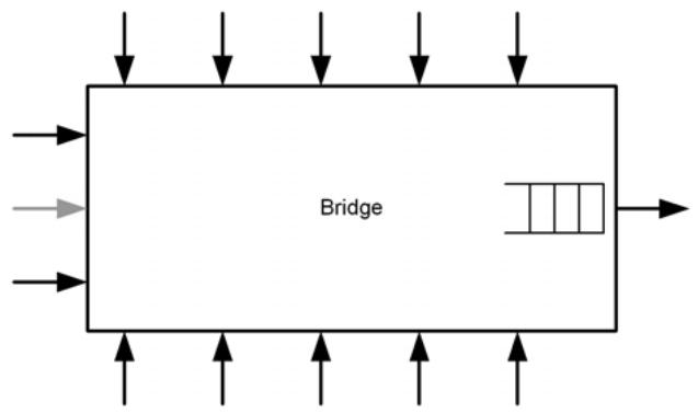
Figure L-6—Fan-in scenario
Assuming that all of the Ports of the Bridge support the same data rate, and the outbound queues of the upstream Bridges are all configured the same as the outbound queue of this Bridge, then the outbound Port would not be able to transmit frames from its queue at the desired, combined data rate of the incoming traffic, as this would require the outbound Port (in this example) to transmit at 20 times its reserved data rate, which would not be permitted by the Stream Reservation Protocol (SRP). It follows that whatever the reserved data rate is on the outbound Port, this must be the same as the sum of the reserved data rates being fed into the inbound Ports.
By allocating the majority of the reserved bandwidth to one of the inbound Ports (shown in grey in Figure L-6) and a very small amount of bandwidth to all of the other inbound Ports, the amount of fan-in data that will be received can be maximized; the grey Port will receive maxBurstX bits of burst data, and all other Ports will receive a single frame of length $\mathrm { M } _ { \mathrm { X } } .$ . Hence, the data that the outbound queue has to handle in this scenario is maxBurs $\mathrm { \dot { x } } + 1 2 \times \mathrm { M _ { X } }$ bits of fan-in data.
NOTE 1—The reason that this choice maximizes the fan-in data burst size is that regardless of how little bandwidth is allocated to the black Ports, they still get to burst a complete frame.
The following is a procedure (not a formula) for determining the maximum amount of fan-in data for a given SR class and output port:
a) Determine $B _ { O } ,$ the maximum possible bandwidth for class X on the output port.
b) For each possible input port i, determine the maximum possible bandwidth $B _ { i }$ for Class X—it is assumed that this information is obtained, by some means, from the transmitting Bridge that is the source of the frames received by i.
c) For input port i, calculate maxBurs $\mathrm { t _ { X , i } }$ using max $( B _ { O } , B _ { i } )$ for the bandwidth. (In the maxBurst formula, use $\mathrm { W _ { X } } = \mathrm { R } _ { 0 } - \operatorname* { m a x } ( B _ { O } , B _ { i } ) . )$
d) Add max(maxBurs $\mathrm { \dot { \cdot } x , \mathrm { i } } ^ { \mathrm { \Omega } }$ to the total fan-in data.
e) Set $B _ { O } = B _ { O } - B _ { i }$ and repeat from step c) until $B _ { O } = 0$ .
f) For each remaining port, add $\mathrm { M } _ { \mathrm { X , i } }$ to the total fan-in data.
The fan-in delay is then equal to the time taken for the total fan-in burst data, computed as shown above, to be output at the line rate of the output port.
NOTE 2—The definition of a measurement interval for stream TSpecs implies a minimum frame transmission rate (8000 frames per second for class A’s 125 us measurement interval). At this frame transmission rate, the frames are smaller and, due to the overhead in small frames, fewer streams are possible (no more than 13 through a 100 Mb port). These constraints should be given due consideration when determining the value to be used for $\mathrm { M } _ { \mathrm { X } }$ and for determining the maximum number of ports contributing to fan-in delay.
Example calculations of fan-in delay can be found in the paper “Calculating the Delay Added by Qav Stream Queue” [B4].
L.3.1.3 Permanent delay
Permanent delay reflects the fact that, if a path through the network is being used continuously at its full capacity for a particular SR class, interfering traffic can cause “permanent” buffer occupancy at the point of congestion. This is illustrated in Figure L-7 through Figure L-10 and the accompanying text.
In Figure L-7 a Talker station, T, has reserved the highest possible bandwidth, $\mathrm { R } _ { \mathrm { X } }$ , for an SR class X stream on the path through 3 Bridges to Listener L. For the purposes of the discussion, RX is the maximum reservable data rate for class X on the outbound Ports of all three Bridges, and Talker T starts transmitting the stream, at the reserved data rate $\operatorname { R } _ { \mathrm { X } } .$ . Assuming that the LANs are short and there is no interfering traffic (i.e., the only traffic being handled is this particular stream), the buffer occupancy in each Bridge will approach zero, as frames can be transmitted onwards as soon as they are received.
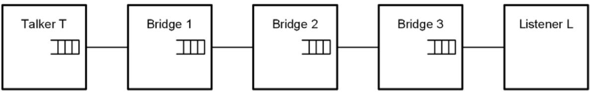
Figure L-7—Permanent delay scenario
In Figure L-8, a second transmission, Q, generates the maximum possible interference to class X (i.e., class X’s next frame for transmission is delayed by $\mathrm { \ q D e l a y _ { X } ) }$ . Talker T’s class X queue fills, and its credit increases to $h i C r e d i t _ { \mathrm { X } }$ (shown on the figure as $\scriptstyle \mathrm { C = C _ { X } ) }$ . Because T is no longer transmitting class X frames, the downstream Bridges are starved of frames to transmit, their buffers are empty, and their credit is zero (C = 0).
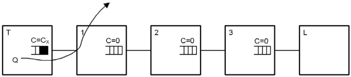
Figure L-8—Building up buffer occupancy—1
In Figure L-9, the interfering traffic goes away, and T is able to transmit a maximum sized class X burst of frames at line rate; once the burst has finished, T reverts to transmitting the stream at the reserved rate $\operatorname { R } _ { \mathrm { X } } .$ As Bridge 1 has no credit, it will have to buffer most of the burst of frames, and as T is sending frames as fast as Bridge 1 can get rid of them, its buffer occupancy will remain at that level unless something else affects that steady state. Bridge 1 ends up with a credit value that hovers around the hiCredit level; the credit in the other Bridges will have credit of 0 or some value between 0 and loCredit as the Bridges receive and transmit frames.
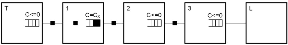
Figure L-9—Building up buffer occupancy—2
If the interfering traffic, Q, starts up again, Talker T’s buffer occupancy will build up again; however, as Bridge 1 still has frames buffered, it can continue to transmit, and the downstream Bridges are not starved of frames, and Bridge 1’s buffer occupancy and credit returns to around 0. When the interference stops, T transmits a burst at line rate, as before, which simply restores Bridge 1’s queue to the state shown in Figure L-9.
If a new interfering frame source, S, starts up that affects class X in Bridge 1, then Bridges 2 and 3 could again be starved of traffic, and the buffer occupancy and credit in Bridge 1 could increase temporarily to $2 \mathrm { C _ { X } }$ (see Figure L-10). When S stops transmitting, then Bridge 2 can create a line rate burst of traffic that will restore its buffer to the previous steady state (Figure L-9), but now Bridge 2 has a permanent buffer loading as shown in Figure L-10.
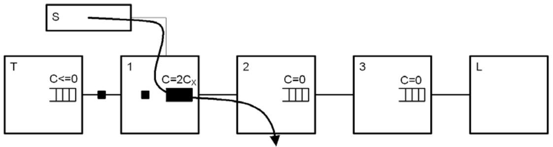
Figure L-10—Building up buffer occupancy—3
This can of course happen for other Bridges in the path, leading eventually to some level of permanent buffer occupancy in each Bridge (Table L-11). The problem does not get any worse from that point on, because no Bridge ever starves (i.e., no Bridge’s credit is set to zero because it runs out of frames to send); starvation is a requirement in order for permanent partial occupancy to be created.
Figure L-11—Building up buffer occupancy—4
It may, therefore, be considered desirable for all Bridges to reserve a little bit more bandwidth than the actual total reserved by the Talkers, so that this “permanent” buffer build-up can drain away. However, this would not make the problem significantly better on the timescales of the output queuing delay, so it does not factor into those calculations, and, of course, this additional capacity would increase the queuing delay at each hop.
NOTE—Many applications have media clocks that are asynchronous to the free-running clock used to determine class measurement intervals. As the two clocks could be operating at the extremes of their permissible variation, it is necessary to reserve more bandwidth than is nominally needed in order to account for the potential difference in clock rate.
Since this kind of event could happen on multiple input ports at the same time, the “permanently buffered” data equals the worst-case fan-in data.
L.3.2 Maximum interference delay and maximum buffer requirement
As discussed in L.3.1, the worst-case interference delay for SR class X on a given Port is the sum of the following three parts:
a) qDelayX [see Equation (L-35) in L.3.1.1]
b) The fan-in delay (see L.3.1.2)
c) The “permanent” buffer contents contribution (see L.3.1.3), which is equal to the worst-case fan-in delay
The buffering requirements for SR class X consist of the following three components:
d) A contribution from the queuing delay, equal to maxBurstX
e) The fan-in burst data size, computed as described in L.3.1.2
f) The “permanent” buffer contents, which is equal to the fan-in burst data size
The fan-in burst size and the permanent buffer contents do not count twice; if a fan-in burst happens, then it becomes the permanent buffer contents. If it happens a second time, it can only happen after a pause that has allowed the permanent buffer loading to drain. So the worst-case buffering requirement for SR class X is simply the sum of the first two elements, maxBurstX [Equation (L-42)] and fan-in burst data size; therefore,
$$
\max \text { Buffering } _ {\mathrm{X}} = \max \text { Burst } _ {\mathrm{X}} + (\text { fan - in burst data size }) _ {\mathrm{X}} \tag {L-45}
$$
The worst-case total buffering requirement for all of the SR classes on a given Port is the sum of the following two parts:
g) The worst-case buffering requirement for the lowest priority SR class on that Port
h) One max-size frame $\mathrm { M } _ { \mathrm { i } , Z }$ for each class Z of higher priority than Class X for each input port i
Since the worst-case buffer requirement for Class X is when it is taking almost all of the bandwidth from the higher-priority classes, the SR priority levels can share buffering space. The only additional requirement is for the fan-in from higher priorities on other Ports. Thus, the SR classes would do well to share their buffer space on each Port.
L.4 Operation of credit-based shaper in Coordinated Shared Network (CSN)
A CSN is a contention-free, QoS-capable, time division multiplexed access network. One of the nodes of the network acts as the Network Coordinator (NC) node granting transmission opportunities to the other nodes of the network. The NC node also acts as the QoS manager of the network.
From the perspective of the specification of the credit-based shaper, a CSN is equivalent to a distributed Bridge. Rather than shaping the AV traffic in the egress nodes, which could lack the buffering resources to do so, the shaping could instead be performed by the CSN’s NC per Class of Service when it schedules transmissions opportunities from the CSN’s ingress to the CSN egress nodes. The behavior of CSN’s egress to another MAC technology should be consistent with the behavior specified in this standard, regardless of how the shaper is implemented.
Annex M
(normative)
Support for PFC in link layers without MAC Control
M.1 Overview
Priority-based Flow Control (PFC) is a function defined for only point-to-point full-duplex links in terms of the M_Control primitives (see 6.6.1). For IEEE 802.3 link layers the M_CONTROL primitives are mapped into the MAC Control MA_CONTROL primitives (IEEE Std 802.1AC), that use the PDU format defined in IEEE Std 802.3-2012, Annex 31D. Other link layers supporting point-to-point full-duplex operations need to define their mapping of the M_CONTROL primitives. This annex describes a PDU format suitable to support PFC.
M.2 PFC PDU format
Figure M-1 shows a PDU format suitable to support PFC.
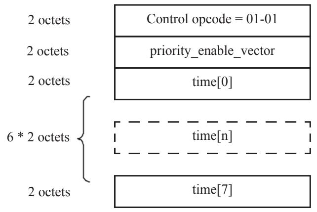
priority_enable_vector definition: time[n] valid if e[n] = 1 time[n] invalid if e[n] = 0
<table><tr><td>ms octet</td><td>ls octet</td></tr><tr><td>0</td><td>e[7] .. e[n] .. e[0]</td></tr></table>
Figure M-1—PFC PDU format
The Control opcode field contains a 2-octet operation code indicating the Control function.
The remaining fields contain the parameters defined in 36.1.2.
Annex N
(informative)
Buffer requirements for PFC
N.1 Overview
To ensure that data frames are not lost due to lack of receive buffer space, receivers must ensure that a PFC M_CONTROL.request primitive is invoked while there is sufficient receive buffer to absorb the data that can continue to be received during the time needed by the remote system to react to the PFC operation. The precise calculation of this buffer requirement is highly implementation dependent. This annex provides an example of how it can be calculated based on a hypothetical delay model. Setting the PFCLinkDelayAllowance (see 12.23) to less than the round-trip delay value can result in frames loss.
Figure N-1 provides an high-level view of the various delays to consider, that include
a) Processing and queuing delay of the PFC request;
b) Propagation delay of the PFC frame across the media;
c) Response time to the PFC indication at the far end; and
d) Propagation delay across the media on the return path.
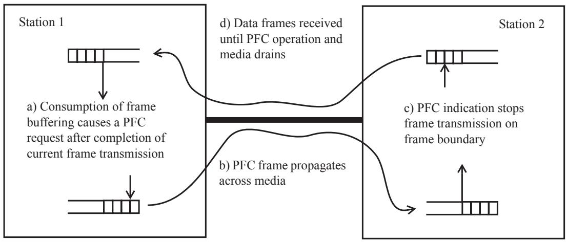
Figure N-1—PFC delays
N.2 Delay model
Figure N-2 shows how to model the various delays between two stations connected by a point-to-point fullduplex IEEE 802.3 link.
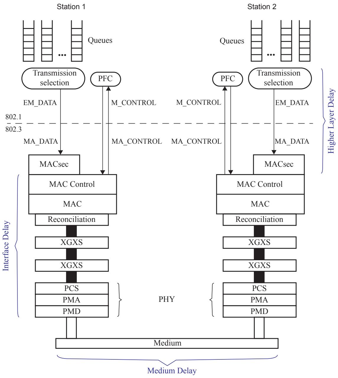
Figure N-2—Delay model
The main delay components shown in Figure N-2 are
a) PFC transmission delay: the time needed by a station to request transmission of a PFC frame after a PFC M_CONTROL.request has been invoked (e.g., because a maximum length data frame can be transmitted).
b) Interface Delay (ID): the sum of MAC Control, MAC/RS, PCS, PMA, and PMD delays. Interface Delay is is dependent on the MAC and physical layer in use.
c) Cable Delay: the number of bits in flight stored in the transmission medium. This delay value is dependent on the selected technology and on the medium length.
d) Higher Layer Delay (HD): the time needed for a queue to go into paused state after the reception of a PFC M_CONTROL.indication that paused its priority. A substantial portion of this delay component is implementation specific.
Figure N-3 shows a possible worst-case delay example.
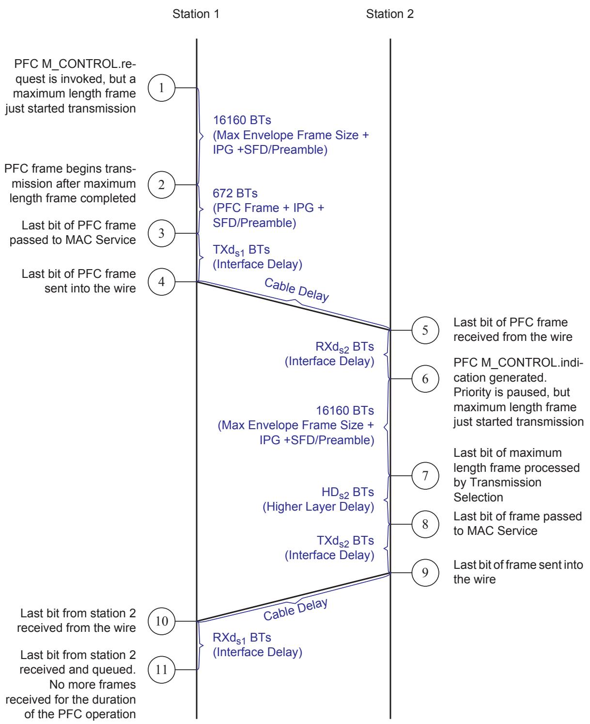
Figure N-3—Worst-case delay
The total Delay Value (DV) is the sum of all delays shown in Figure N-3:
$$
\mathrm{DV} = 2 ^ {*} (\text {Max Frame}) + (\text {PFC Frame}) + 2 ^ {*} (\text {Cable Delay}) + \mathrm{TXd} _ {\mathrm{s} 1} + \mathrm{RXd} _ {\mathrm{s} 2} + \mathrm{HD} _ {\mathrm{s} 2} + \mathrm{TXd} _ {\mathrm{s} 2} + \mathrm{RXd} _ {\mathrm{s} 1}
$$
For any given station the Interface Delay includes both transmit and receive paths $( \mathrm { i . e . , I D = T X d + R X d } )$ . Therefore:
$$
\mathrm{DV} = 2 ^ {*} (\text { Max Frame }) + (\text { PFC Frame }) + 2 ^ {*} (\text { Cable Delay }) + \mathrm{ID} _ {\mathrm{s1}} + \mathrm{ID} _ {\mathrm{s2}} + \mathrm{HD} _ {\mathrm{s2}}
$$
Usually the peer stations connected by a point-to-point link use the same technology, therefore $\mathrm { I D } _ { \mathrm { s 1 } } = \mathrm { I D } _ { \mathrm { s } 2 } \mathrm { : }$
$$
\mathrm{DV} = 2 ^ {*} (\text { Max Frame }) + (\text { PFC Frame }) + 2 ^ {*} (\text { Cable Delay }) + 2 ^ {*} \mathrm{ID} + \mathrm{HD} _ {\mathrm{s} 2}
$$
N.3 Interface Delay
The Interface Delay comprises all delay components below the MAC Control Client, excluding the cable delay. Table N-1 shows the Interface Delay constraints for some IEEE 802.3 interfaces.
Table N-1—IEEE 802.3 Interface Delays
<table><tr><td>Sublayer</td><td>Maximum RTT (bit times)</td><td>Maximum RTT (pause quanta)</td><td>Reference (subclause of IEEE Std 802.3-2012)</td></tr><tr><td>10G MAC Control, MAC, and RS</td><td>8192</td><td>16</td><td>46.1.4</td></tr><tr><td>XGXS and XAUI</td><td>2048</td><td>4</td><td>48.5</td></tr><tr><td>10GBASE-X PCS</td><td>2048</td><td>4</td><td>49.2.15</td></tr><tr><td>10GBASE-R PCS</td><td>3584</td><td>7</td><td>50.3.7</td></tr><tr><td>LX4 PMD</td><td>512</td><td>1</td><td>53.2</td></tr><tr><td>CX4 PMD</td><td>512</td><td>1</td><td>54.3</td></tr><tr><td>Serial PMA and PMD</td><td>512</td><td>1</td><td>52.2</td></tr><tr><td>10GBASE-T</td><td>25 600</td><td>50</td><td>55.11</td></tr></table>
N.4 Cable Delay
The Cable Delay is the propagation delay over the transmission medium and can be approximated by the following equation:
$$
\text { Cable Delay } = \text { Medium Length } * \frac {1}{B T \times v}
$$
where is the signal propagation speed in the medium and BT is the bit time of the medium.
N.5 Higher Layer Delay
The Higher Layer Delay comprises the delay components between the MAC Control Client and the port Transmission Selection. Example of these delays are MACsec and implementation specific delays.
For link speeds of up to 10Gb/s, MACsec constrains each of the transmit delay and the receive delay to a maximum of 19 360 bit times (see 36.1.3.3).
This standard constrains the implementation specific delays to be less that 614.4 ns (see 36.1.3.3). This delay is equivalent to 6144 bit times at the speed of 10Gb/s.
N.6 Computation example
A station needs to be capable of buffering DV bit times of data to ensure no frame loss due to congestion. The worst case is with a 10GBASE-T PHY. Assuming MACsec is not supported, this results in the following:
Maximum envelope frame size: 2000 octets, 16 160 bit times;
PFC frame size: 64 octets, 672 bit times;
— XGMII MAC/RS and XAUI interface: 8192 + 2 * 2048 = 12 288 bit times;
10GBASE-T Delay: 25 600 bit times;
100 meters Cat6 cable: 5556 bit times (computed assuming $\mathrm { ~ u ~ } = 0 . 6 \ ^ { * } \mathrm { ~ c ~ } _ { \mathrm { \scriptsize { i } } }$ , where c is the speed of the light in meters per second);
— HD = 6144.
The total Delay Value in this scenario results as follows:
$$
\mathrm{DV} = 2 ^ {*} (\text { Max Frame }) + (\text { PFC Frame }) + 2 ^ {*} (\text { Cable Delay }) + 2 ^ {*} \mathrm{ID} + \mathrm{HD} _ {\mathrm{s} 2}
$$
$$
\mathrm{DV} = 2 * (1 6 1 6 0) + (6 7 2) + 2 * (5 5 5 6) + 2 * (2 5 6 0 0) + 2 * (1 2 2 8 8) + 6 1 4 4 = 1 2 6 0 2 4 \text { bit times }
$$
For this case, the amount of buffering needed to ensure no frame loss due to congestion results to be 126 024 bit times, roughly equivalent to 15.5 KBytes.
If MACsec is used, the High Layer Delay is incremented by 19 360 bit times; therefore, the total Delay Value results as follows:
$$
\mathrm{DV} = 2 * (1 6 1 6 0) + (6 7 2) + 2 * (5 5 5 6) + 2 * (2 5 6 0 0) + 2 * (1 2 2 8 8) + 2 5 5 0 4 = 1 4 5 3 8 4 \text { bit times }
$$
For this case, the amount of buffering needed to ensure no frame loss due to congestion results to be 145 384 bit times, roughly equivalent to 18 KBytes.
Annex O
(informative)
Preserving the integrity of FCS fields in MAC Bridges
O.1 Background
When relaying frames between Ports of a MAC Bridge, one of the functions of the Bridge is to regenerate the FCS field in accordance with the MAC procedures that apply to the medium access method through which the frame will be relayed. One of the requirements of the MAC Bridge standard is that any such regeneration of the FCS shall not increase the level of undetected FCS errors that are experienced on the transmitting MAC over that which would be experienced by preserving the FCS. The point at issue here is only the undetected error rate; a conformant Bridge will discard frames that are received with an FCS error; however, there is a finite possibility of undetectable corruption taking place, i.e., the frame is corrupted, but the FCS algorithm does not reveal the error.
This annex looks at the various cases that apply to the operation of the MAC Bridge with respect to FCS regeneration and the alternative approaches that can be taken in order to address the cases. The following cases need to be considered:
a) The source and destination media access methods are identical from the point of view of the operation of the FCS algorithm.
NOTE—This is the case, for example, where the source and destination media access methods are identical. It could also happen with dissimilar media access methods if the FCS coverage, the FCS algorithm, the definitions of the fields covered by the FCS, and the bit/octet ordering are the same in both media access methods.
b) The source and destination media access methods differ from the point of view of the operation of the FCS algorithm.
c) The data covered by the FCS is not modified by the operation of the relay function of the Bridge.
d) The data covered by the FCS is modified by the operation of the relay function of the Bridge.
In each case, it is important to ensure that there is a low probability of additional undetected errors being generated by corruption of the data portion of the frame between removal of the old FCS and computation of the new one, which would result in the transmitted frame carrying invalid data and a valid FCS. Such corruption might occur, for example, as a result of the effect of environmental noise on the operation of the Bridge hardware.
If both item a) and item c) are true, then the FCS carried in the received frame is still valid, and the ideal approach would be to reuse this value as the FCS for the transmitted frame.
If either item b) or item d) are true, then it will be necessary for the Bridge to recalculate the FCS on transmission, and may therefore need to take additional precautions against in-memory corruption causing increased undetected FCS error levels.
O.2 Basic mathematical ideas behind CRC and FCS
The standard CRC algorithm is based on the following ideas:
a) An n-bit message is regarded as a polynomial, M(x), of degree n-1.
b) In order to generate a CRC value of length r bits, a generator polynomial, G(x), is used, of degree r
c) The value of the last r bits of M(x) are chosen such that M(x) ÷ G(x) has a remainder of 0 [i.e., M(x) = 0 mod G(x)].
Messages can be added, in which each coefficient is 0 or 1:
d) M3(x) = M1(x) + M2(x). Messages are added together by bit-wise addition (XOR) of coefficients with the same bit position (i.e., coefficients with the same exponent).
Subtraction of messages:
e) Addition and subtraction are equivalent operations (as A = A XOR B XOR B); hence, using the messages in example d) above, M1(x) can be regenerated from M3(x) by adding M2(x).
Linearity:
f) If M(x) = 0 mod G(X), then (M(x) + E(x)) = 0 mod G(x) IFF E(x) = 0 mod G(x). In other words, if an error pattern, E(x), is added to a message, M(x), then the resultant message will give no remainder when divided by the generator polynomial if both M(x) and E(x) gave no remainder when divided by the generator polynomial.
g) xmM(x) = 0 mod G(x) IFF M(x) = 0 mod G(x). A message can be shifted by adding zero padding without affecting the integrity of the CRC.
h) Thus, the CRC algorithm has the property that it will detect any burst error, of length r bits or less, applied to the message, as such an error must result in a nonzero remainder when the message is divided by the generator polynomial. Alternatively, adding two messages together, both of which have valid CRCs, results in a message with a valid CRC.
In Ethernet, the algorithm used differs from the standard CRC, and is known as an FCS. The FCS is based on the CRC but with the following differences:
— The first 32 bits of M(x) are complemented before the FCS value is calculated.
— A CRC value is calculated, as described above, by dividing the first n-32 bits of M(x) by G(x) and taking the remainder as the CRC value.
— The CRC value is complemented and inserted as the last 32 bits of M(x).
By application of the addition and linearity rules, item d) and item f) above, the Ethernet frame with its FCS can be viewed as consisting of the following component messages, added together:
— An n-bit message, M(x), carrying a standard CRC as the last 32 bits.
— An n-bit “FCS adjustment factor,” An(x), which adjusts the CRC to form an FCS.
Figure O-1 illustrates the conversion of a message with a CRC to the equivalent message with an FCS, by the addition of the adjustment factor. The adjustment factor consists of the following two components:
The first component, when added to M(x), contributes an adjustment to the CRC, which is equivalent to the effect of complementing the first 32 bits of M(x) before calculating the CRC bits, and complements the first 32 bits of M(x).
The second component, when added to the partially adjusted M(x), restores the first 32 bits of M(x) to their original value, and complements the (adjusted) CRC to form the final FCS.
<table><tr><td>Mcrc(x)</td><td colspan="2">Data - (n-4) octets</td><td>32-bit CRC</td></tr><tr><td rowspan="2">+
An(x) =</td><td>FF-FF-FF-FF</td><td>(n-8) octets of 00</td><td>32-bit CRC</td></tr><tr><td>FF-FF-FF-FF</td><td>(n-8) octets of 00</td><td>FF-FF-FF-FF</td></tr><tr><td>Mfcs(x)</td><td colspan="2">Data - (n-4) octets</td><td>32-bit FCS</td></tr></table>
Figure O-1—Converting a CRC to an FCS
O.3 Detection Lossless Circuit approach
This approach is illustrated in Figure O-2. The basis of this approach is that the FCS used in the modified message is always recomputed from scratch using the normal FCS generation algorithm (Check Generator B); however, the original message data and FCS are also used as an input to an FCS checker (Checker A) in order to check that the inputs to the FCS generator were correct. Hence, if errors are introduced into the message while it is in memory in the Bridge in the time period since the message was received and FCSchecked, then Checker A will detect the error at the same time as the new FCS for the modified message is being generated.
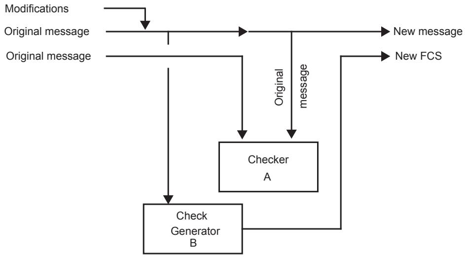
Figure O-2—Detection Lossless Circuit
Checker A is fed both with the original message in its unmodified form, and with the original message as used in the construction of the new message; this occurs after (or simultaneously with) the generation of the new FCS by Check Generator B. Any discrepancies detected by Checker A indicate that the information used to generate the new message and its FCS are suspect, and that the message should therefore be discarded.
O.4 Algorithmic modification of an FCS
In cases where the need to recalculate the FCS comes about as a result of changes to the data rather than by changes in the operation of the FCS algorithm, one option, rather than recalculating an FCS from scratch for a given message, is to examine the changes that have been made to the message and to calculate an FCS adjustment factor that reflects those changes. There are two cases, as follows:
a) The overall length of the message is unchanged, but the contents of one or more octets of data covered by the FCS have changed.
b) The overall length of the message has increased or decreased, as a result of the addition or removal of octets covered by the FCS, but the contents of the original octets is unchanged (although some may have been shifted in position as a result of the insertion/deletion).
O.4.1 Data changed, length unchanged
Adjustment of a message, MF1(x), in order to change the value of a field F from current value $\mathrm { F } _ { 1 }$ to new value $\mathrm { F } _ { 2 }$ consists of the following steps:
Remove the FCS adjustment factor for a message of length n, An(x).
— Remove the contribution to the message and its FCS provided by the current value of the field, $\mathrm { F } _ { 1 } ( \mathrm { x } )$ .
— Add the contribution to the message and its FCS provided by the new value of the field, $\mathrm { F } _ { 2 } ( \mathrm { x } )$ .
— Add the FCS adjustment factor for a message of length n, An(x).
In other words,
$$
\mathrm{MF} _ {2} (\mathrm{x}) = \mathrm{MF} _ {1} (\mathrm{x}) - \mathrm{An} (\mathrm{x}) - \mathrm{F} _ {1} (\mathrm{x}) + \mathrm{F} _ {2} (\mathrm{x}) + \mathrm{An} (\mathrm{x})
$$
The addition and subtraction of An(x) cancel each other out, so,
$$
\mathrm{MF} _ {2} (\mathrm{x}) = \mathrm{MF} _ {1} (\mathrm{x}) - \mathrm{F} _ {1} (\mathrm{x}) + \mathrm{F} _ {2} (\mathrm{x})
$$
Also, the correction factors $\mathrm { F _ { 1 } } ( \mathrm { x } )$ and $\mathrm { F } _ { 2 } ( \mathbf { x } )$ can be replaced by a single factor, $\mathrm { F } _ { 3 } ( \mathrm { x } )$ , which is the contribution to $\operatorname { M } ( \mathbf { x } )$ and its FCS that would be provided by the value of Field F that would be produced by $\mathrm { F } _ { 1 } \mathrm { X O R } \mathrm { F } _ { 2 } . \mathrm { S o } _ { \mathrm { f } }$ ,
$$
\mathrm{MF} _ {2} (\mathrm{x}) = \mathrm{MF} _ {1} (\mathrm{x}) + \mathrm{F} _ {3} (\mathrm{x})
$$
This is shown in Figure O-3.
Alternatively,
$$
\text { FCS of } \mathrm{MF} _ {2} (\mathrm{x}) = (\text { FCS of } \mathrm{MF} _ {1} (\mathrm{x})) + \text { adjustment }
$$
where
$$
\text { Adjustment } = (\text { FCS of F } _ {1} (\mathrm{x})) + (\text { FCS of F } _ {2} (\mathrm{x}))
$$
or equivalently,
$$
\mathrm{FCS} \text { of } \mathrm{MF} _ {2} (\mathrm{x}) = (\mathrm{FCS} \text { of } \mathrm{MF} _ {1} (\mathrm{x})) + (\mathrm{FCS} \text { of } \mathrm{F} _ {3} (\mathrm{x}))
$$
The adjustment factor (FCS of $\mathrm { F } _ { 3 } ( \mathbf { x } ) )$ is incidentally the same factor that would be used if the value of F were to be changed back from $\mathrm { F } _ { 2 } \mathrm { t o } \mathrm { F } _ { 1 }$ .
<table><tr><td><eq>MF_{1}(x)</eq></td><td>x data octets</td><td><eq>F_{1}</eq></td><td>y data octets</td><td>32-bit FCS</td></tr><tr><td>- F1(x)</td><td>x octets of 00</td><td><eq>F_{1}</eq></td><td>y octets of 00</td><td>32-bit CRC</td></tr><tr><td>+ F2(x)</td><td>x octets of 00</td><td><eq>F_{2}</eq></td><td>y octets of 00</td><td>32-bit CRC</td></tr><tr><td>= <eq>MF_{2}(x)</eq></td><td>x data octets</td><td><eq>F_{2}</eq></td><td>y data octets</td><td>32-bit FCS</td></tr></table>
Note also that
<table><tr><td>F1(x)</td><td>x octets of 00</td><td><eq>F_{1}</eq></td><td>y octets of 00</td><td>32-bit CRC</td></tr><tr><td>+ F2(x)</td><td>x octets of 00</td><td><eq>F_{2}</eq></td><td>y octets of 00</td><td>32-bit CRC</td></tr><tr><td>= <eq>F_{3}(x)</eq></td><td>x octets of 00</td><td>F1 XOR <eq>F_{2}</eq></td><td>y octets of 00</td><td>32-bit FCS</td></tr></table>
Figure O-3—Field change adjustment
The relative simplicity of this case (relative to the case where the length changes) is a consequence of linearity and the fact that the FCS adjustment factor, An(x), is constant for any given message length n, not a function of the data carried in the message.
O.4.2 Length changed, original data unchanged
Adjustment of a message M(x) of length n to cater for an inserted field, I, of length i involves the following steps:
Remove the FCS adjustment factor for a message of length n, An(x);
Remove the contribution to the message and FCS that is provided by the header portion of the message (the portion before the inserted field), H(x);
Add the contribution to the message and FCS that is provided by the header plus the inserted field I, HI(x);
— Add the FCS adjustment factor for a message of length n+i, An+i(x).
So,
$$
\mathrm{MI} (\mathrm{x}) = \mathrm{M} (\mathrm{x}) - \mathrm{An} (\mathrm{x}) - \mathrm{H} (\mathrm{x}) + \mathrm{HI} (\mathrm{x}) + \mathrm{An} + \mathrm{i} (\mathrm{x})
$$
This is shown in Figure O-4.
Alternatively,
$$
\text { FCS of MI(x) } = (\text { FCS of M(x)) } + \text { adjustment }
$$
where
$$
\text { adjustment } = (\text { CRC of An(x)) } + (\text { CRC of H(x)) } + (\text { CRC of HI(x)) } + (\text { CRC of (An+ i(x)) }
$$
As with the field change example, the value of adjustment is the same adjustment factor that would be used to adjust the FCS of MI(x) if field I were to be removed from the message.
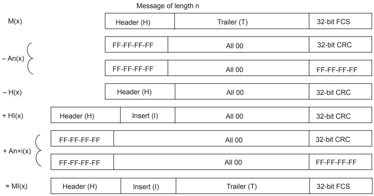
Figure O-4—Field insertion adjustment
O.4.3 Preservation of detectability
With either of the algorithmic adjustment methods described here, the important question is whether the ability of the FCS to detect errors in the message is preserved across these transformations; in other words, if a detectable error pattern, E(x), is added to the message M(x) before the modification, addition, or removal of a field, is that error still detectable after the message has been adjusted.
NOTE—The following analysis assumes that E(x) is a detectable error pattern, of length 32 bits or less. Analysis of the performance of this method with longer error patterns has not been attempted here.
In the cases where the error component is in those parts of the message that are not affected (changed or shifted) by the transformation, it is reasonably apparent that, as the transformation takes no account of the portion of the message that is in error, the detectability of that error is unchanged.
In the case of a field change, where field $\mathrm { F } _ { 1 }$ is to be replaced with $\mathrm { F } _ { 2 } ,$ and E(x) had been applied in some part of the message before changing the field, the new FCS value would be calculated as follows:
$$
\mathrm{FCS} \text { of } \mathrm{MF} _ {2} (\mathrm{x}) = (\mathrm{FCS} \text { of } \mathrm{MF} _ {1} (\mathrm{x})) + (\mathrm{FCS} \text { of } \mathrm{F} _ {1} (\mathrm{x})) + (\mathrm{FCS} \text { of } \mathrm{F} _ {2} (\mathrm{x}))
$$
However, the correction factor that is applied to the FCS contains components based only on $\mathrm { F } _ { 1 }$ and $\mathrm { F } _ { 2 } ,$ and no contribution related to the error pattern E(x). Therefore, after the value of the field has been changed to $\mathrm { F } _ { 2 } ,$ the new FCS value as calculated above will still be capable of detecting error pattern E(x), regardless of where the error pattern appears in the message.
In the case of a field insertion (or removal, as insertion and removal have already been shown to be equivalent), where E(x) has been applied to H(x), the correction factor that is applied to the FCS will contain two components related to E(x); the first based on E(x) in its original position, and the second based on E(x) shifted by i, the length of the inserted field, as follows:
$$
\text { FCS of MI(x) } = (\text { FCS of M(x)) } + \text { adjustment }
$$
where
$$
\begin{array}{l} \text { adjustment } = (\text { CRC of An(x)) } + (\text { CRC of H(x)) } + (\text { CRC of HI(x)) } + (\text { CRC of (An+ i(x)) } \\ + (\text { CRC of E(x) }) + (\text { CRC of (E(x) shifted by i)) } \\ \end{array}
$$
The presence of the (CRC of E(x)) component ensures that the final message will still indicate an FCS error. (Note that, even if (CRC of E(x)) and (CRC of (E(x) shifted by i)) turn out to be the same value, the final message will still indicate an FCS error, as its FCS is now correct for the value of MI(x) without the error component.)
The above does not exhaustively analyze all the cases of field insertion and removal, and in particular, does not analyze the cases where the error pattern crosses the insertion/removal boundaries; however, it can be shown that the error detection characteristics of the FCS are preserved in these cases as well.
The conclusion from the above examples is that, as long as the field values used in the calculation of these FCS correction factors are the same as the field values present in the original and final messages (e.g., that the same value of H+E is used both in its original and shifted forms), then the properties of the FCS are preserved. However, if different values are used for calculation of the correction factor from those present in the messages (as could happen, for example, as a result of in-memory corruption), then the properties of the FCS are no longer preserved. Hence, if these algorithmic approaches are used, it is necessary to design the implementation in a manner that ensures that these conditions are met.
O.5 Conclusions
Where it is necessary to recalculate the FCS before transmission, then either the algorithmic FCS modification approaches or the Detection Lossless Circuit approach offer a basis for this to be achieved while still preserving the error detection coverage that was provided by the original FCS.
The Detection Lossless Circuit approach requires access to the entire contents of the original message, to compute the necessary FCS adjustments or to check the integrity of the data that is being used to create the new message and its FCS. In contrast, the algorithmic approach requires access only to the header, insert, and FCS of the original message.
With the algorithmic approach, care needs to be taken in the implementation in order to ensure that the inputs to the correction algorithms are consistent with the contents of the original and modified messages, whereas in the Detection Lossless Circuit, such consistency checking is inherent in the way that the original FCS is used to check the generation of the new FCS.
Annex P
(informative)
Frame duplication and misordering
Although RSTP provides a single loop-free path between communicating stations at any instant, RSTP can reconfigure the active topology of the Bridged Network in less time than it can take a frame to transit from its source to its destination(s). This annex explains how this can result in user data frame duplication and misordering and examines the possible QoS impact.
NOTE—The ForceVersion parameter provided by RSTP allows network administrators to choose slower reconfiguration, thereby trading off service availability against the risk of duplication and misordering.
P.1 Background
In a network of Bridges implementing STP, specified in the 1998 and earlier editions of IEEE Std 802.1D [B9], delays in transitioning Ports to Forwarding ensure that frames in transit prior to a network reconfiguration are delivered or discarded before being forwarded on the new active topology. In such a network, the only source of misordered or duplicated frames is a “magically healed” LAN between two Bridges, for example, as a result of accidental interconnections between shared media hubs.
RSTP, by design, can transition a Port to Forwarding very rapidly. A Root Port transition can occur as rapidly as the hardware can manage it, and a Designated Port transition in the time it takes to transmit two frames from separate stations on a single LAN. It is conceivable that a reconfiguration can take place, and a Port be made Forwarding as a result, while frames forwarded on the prior active topology are still in transit.
P.2 Frame duplication
A unicast frame whose destination address has been learned by the Bridges that can forward it, can only be buffered for transmission on one Port of one Bridge at any one time, and cannot be duplicated.
A unicast frame whose destination address has not been learned, can be flooded by some Bridges, and therefore buffered on multiple outbound Ports at the same time, and can be duplicated during network reconfiguration. Figure P-1 provides an example. In this network fragment, the Root Bridge is assumed to be somewhere to the left of Bridge A’s Port A1, and the Port Path Costs of the three Bridges result in the active topology shown, with Port B3 Discarding and the remaining Ports all Forwarding.
If the configuration is stable, a unicast frame arriving at A1 and destined for an unlearned unicast destination reachable through B2 is flooded by Bridge A to its Ports A2 and A3, and by Bridge C to its Ports C2 and C3. As B3 is Discarding, only the frame reaching B1 is transmitted through B2, and the destination receives a single copy of the frame.
During reconfiguration the following sequence of events can occur:
a) A receives the frame through A1 and transmits copies of it through A2 and A3.
b) B and C each receive a copy and queue them for transmission through B2, C2, and C3.
c) B2 transmits its copy of the frame to its destination.
d) B detects that LAN A2-B1 has failed, and immediately makes B3 Forwarding as its new Root Port.
e) C2 transmits its copy of the frame, B receives and transmits this second copy through B2.
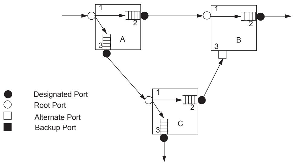
Figure P-1—Frame duplication scenario
The destination station, reachable through B2, receives the same frame twice. However, any subsequent response from the destination station would cause the address to be learned. While this reconfiguration will itself cause addresses to be flushed from the Bridge’s FDBs of Bridges, the flushing commences after the Port becomes Forwarding, and will not increase frame duplication unless there are further changes in the active topology.
Multicast frames are all potentially subject to duplication on reconfiguration events, as they can be buffered at multiple outbound Ports. Frame duplication does not cause problems in known multicast LAN protocols.
The risk of frame duplication depends upon network configuration, frequency of reconfiguration, equipment implementation details, and the characteristics of the network traffic that determine how long each frame is likely to be buffered in each Bridge, and therefore cannot be quantified without reference to the a particular network.
P.3 Frame misordering
A change in the active topology between two communicating end stations can result in frame misordering, as a frame sent after reconfiguration can experience a lower transit delay, being queued at fewer Bridge Ports or for less time. Figure P-2 provides an example. In this network fragment a station connected to A1 is communicating with a station connected to B2. Prior to reconfiguration, A2 is an Alternate Port and is Discarding; all traffic between the two stations is relayed by Bridge C. During reconfiguration the following sequence of events can occur:
a) Frame F1 is received through A1, buffered and transmitted through A3, received through C1 and buffered awaiting transmission through C2.
b) A detects that LAN A3-C1 has failed, and immediately makes A2 Forwarding as its new Root Port.
c) Frame F2 is received through A1, transmitted through A2 to B1, and then transmitted through B2.
d) F1 is transmitted through C2 to B3, and then transmitted through B2.
Clearly, the receiving station connected to B2 sees the frames in the reverse of the order in which the originating station transmitted them.
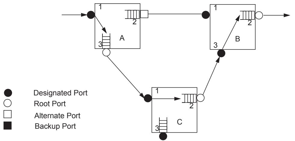
Figure P-2—Frame misordering scenario
As with frame duplication, the overall risk of frame misordering depends upon network configuration, frequency of reconfiguration, equipment implementation details, and the characteristics of the network traffic that determine how long each frame is likely to be buffered in each Bridge, and therefore cannot be quantified without reference to the a particular network.
Some LAN protocols, for example LAT, LLC2, and NETBEUI, are sensitive to misordering, so even a low incidence of misordering could result in perceived problems in networks that support these protocols.
P.4 Other considerations
The possibility that frames may be stored “in transit” on old routes after a reconfiguration has completed means that there is also a possibility that addresses will be mis-learned, leading to a risk of denial of service for the addresses concerned. Hence, it is necessary to run short aging timers for a period after a reconfiguration to allow such frames to be delivered or discarded.
The Bridge model described in this standard does not include the concept of queuing on input to a Port; however, practical Bridge designs generally include some input queuing. While this is not a solution to the effects described above, a Bridge should flush any input queue associated with a Port that becomes Disabled. This behavior is consistent with the Bridge model; if a frame is in an input queue, it has not been received as far as the Bridge Port is concerned, and therefore should not be received after the Port becomes Disabled.
Annex Q
[B51] SMPTE 259M-2008, SMPTE Standard for Television—SDTV Digital Signal/Data—Serial Digital Interface, 2008. See section 8.60
(informative)
[B13] IEEE Std 1722™, IEEE Standard for Layer 2 Transport Protocol for Time Sensitive Applications in Bridged Local Area Networks.
[B35] IETF RFC 5681, TCP Congestion Control, September 2009.
[B52] SMPTE 292M-2008, SMPTE Standard 1.5 Gb/s Signal/Data Serial Interface, 2008. See subsection 4.3.
Bibliography
NOTE—See Figure 5.3 for the ABTP common stream data header format. Also see IEC 61883-6, Consumer audio/ video equipment—Digital Interface—Part 6: Audio and music data transmission protocol, Second edition, 2005-10, and IEC 61883-4, Consumer audio/video equipment—Digital Interface—Part 4: MPEG2-TS data transmission, Second edition, 2004-08.
[B36] IETF RFC 6328, IANA Considerations for Network Layer Protocol Identifiers, July 2011.
[B53] SMPTE 424M-2008, SMPTE Standard for Television—3 Gb/s Signal/Data Serial Interface, 2008. See subsection 4.3.
Bibliographical references are resources that provide additional or helpful material but do not need to be understood or used to implement this standard. Reference to these resources is made for informational use only.
[B14] IETF RFC 793 (STD0007), Transmission Control Protocol, September 1981.54
[B37] IETF RFC 6329, IS-IS Extensions Supporting IEEE 802.1aq Shortest Path Bridging, April 2012.
[B15] IETF RFC 1321, The MD5 Message-Digest Algorithm, April 1992.
[B38] ISO 6937-2, Information technology—Coded graphic character set for text communication—Latin alphabet.55
[B1] Alizadeh, M., Atikoglu, B., Kabbani, A., Lakshmikantha, A., Pan, R., Prabhakar, B., and Seaman, M., “Data Center Transport Mechanisms: Congestion Control Theory and IEEE Standardization,” Proceedings of The 46th Annual Allerton Conference on Communication, Control and Computing, Urbana-Champaign, Sept. 2008, Invited paper.
[B16] IETF RFC 1323, TCP Extensions for High Performance, May 1992.
[B39] ISO/IEC TR 11802-1:1997, Information Technology—Telecommunications and Information Exchange Between Systems—Local and Metropolitan Area Networks—Technical Reports and Guidelines—Part 1. The Structure and Coding of Logical Link Control Addresses in Local Area Networks.56
[B2] Asynchronous Transfer Mode (ATM): A collection of equipment and standards used for telecommunications and data transfer. (See http://www.itu.int/ITU-T/ and http://www.broadbandforum.org.)
[B17] IETF RFC 1633, Integrated Services in the Internet Architecture: An Overview, June 1994.
[B40] ITU-T Recommendation G.806, Characteristics of transport equipment — Description methodology and generic functionality.57
[B3] Binary Increase Congestion control—Transmission Control Protocol (BIC-TCP); http:// www4.ncsu.edu/~rhee/export/bitcp.pdf.
[B18] IETF RFC 2210, The Use of RSVP with IETF Integrated Services, September 1997.
[B41] ITU-T Recommendation G.8021/Y.1341 (08/2004), Characteristics of Ethernet transport network equipment functional blocks.
[B4] Calculating the Delay Added by Qav Stream Queue (see http://www.ieee802.org/1/files/public/ docs2009/av-fuller-queue-delay-calculation-0809-v02.pdf).
[B19] IETF RFC 2211, Specification of the Controlled-Load Network Element Service, September 1997.
[B42] [ITU-T Recommendation G.8031/Y.1342 (11/2009), Ethernet linear protection switching.
[B5] IEEE Std 802a™-2003, IEEE Standard for Local and Metropolitan Area Networks: Overview and Architecture—Amendment 1: Ethertypes for Protoypes and Vendor-specific Protocol Development.52, 53
[B20] IETF RFC 2212, Specification of Guaranteed Quality of Service, September 1997.
[B43] ITU-T Recommendation I.610 (02/1999), B-ISDN operation and maintenance principles and functions.
[B6] IEEE Std 802.1AE™-2006, IEEE Std for Media Access Control (MAC) Security.
[B21] IETF RFC 2215, General Characterization Parameters for Integrated Service Network Elements, September 1997.
[B44] ITU-T Recommendation X.25 (10/1996), Public Data Networks: Interfaces—Interfaces between Data Terminal Equipment (DTE) and Data Circuit-terminating Equipment (DCE) for Terminals Operating in the Packet Mode and Connected to Public Data Networks by Dedicated Circuit.
[B7] IEEE Std 802.1AS™, IEEE Standard for Local and metropolitan area networks—Timing and Synchronization for Time-Sensitive Applications in Bridged Local Area Networks.
[B22] IETF RFC 2309, Recommendations on Queue Management and Congestion Avoidance in the Internet, April 1998.
[B45] MEF Technical Specification 10.3 (MEF 10.3), Ethernet Service Attributes Phase 3.58
[B8] IEEE Std 802.1D™, 1993 Edition [ISO/IEC 10038:1993], IEEE Standard for Information technology—Telecommunications and information exchange between systems—Local area networks— Media Access Control (MAC) bridges.
[B23] IETF RFC 2475, An Architecture for Differentiated Services, December 1998.
[B46] MEF Technical Specification 16 (MEF 16), Ethernet Local Management Interface (E-LMI).
[B9] IEEE Std 802.1D™, 1998 Edition [ISO/IEC 15802-3:1998], IEEE Standard for Information technology—Telecommunications and information exchange between systems—Local and metropolitan area networks—Common specifications—Part 3: Media Access Control (MAC) Bridges.
[B24] IETF RFC 2597, Assured Forwarding PHB Group, June 1999.
[B47] MEF Technical Specification 26 (MEF 26), External Network Network Interface (ENNI)—Phase 1.
[B10] IEEE Std 802.1D™-2004, IEEE Standard for Local and metropolitan area networks—Media Access Control (MAC) Bridges.
[B25] IETF RFC 2814, SBM (Subnet Bandwidth Manager): A Protocol for Admission Control over IEEE 802-style Networks, May 2000.
[B48] MoCA MAC/PHY Specification Extensions v1.1, MoCA-M/P-SPEC-V1.1-06162009, Multimedia over Coax Alliance (MoCA), June 16, 2009.59
[B11] IEEE Std 802.2™, 1998 Edition [ISO/IEC 8802-2:1998], IEEE Standard for Information technology—Telecommunications and information exchange between systems—Local and metropolitan area networks—Specific requirements—Part 2: Logical Link Control.
[B26] IETF RFC 2815, Integrated Service Mappings on IEEE 802 Networks, May 2000.
[B49] MoCA MAC/PHY Specification v2.0, MoCA_Specification_v2-131121, Nov. 2013.
[B12] IEEE Std 802.11™-2012, Standard for LAN/MAN—Specific requirements Part 11: Wireless LAN Medium Access Control (MAC) and Physical Layer (PHY) Specifications.
[B27] IETF RFC 2816, A Framework for Providing Integrated Services Over Shared and Switched LAN Technologies, May 2000.
[B50] Multiprotocol Label Switching (MPLS): A standard for label-based forwarding in an IP network. The standard is specified in several RFCs (see http://www.ietf.org/html.charters/mpls-charter.html) and ITU-T recommendations (see http://www.itu.int/ITU-T/).
[B28] IETF RFC 2863, The Interfaces Group MIB, June 2000.
[B29] IETF RFC 3031 (Proposed standard), Multiprotocol Label Switching Architecture; The Internet Society; http://www.ietf.org/rfc/rfc3031.txt.
[B30] IETF RFC 3246, An Expedited Forwarding PHB (Per-Hop Behavior), March 2002.
[B31] IETF RFC 3270, Multi-Protocol Label Switching (MPLS) Support of Differentiated Services, May 2002.
[B32] IETF RFC 4663, Transferring MIB Work from IETF Bridge MIB WG to IEEE 802.1, September 2006.
[B33] IETF RFC 4960, Stream Control Transmission Protocol, September 2007.
[B34] IETF RFC 5306, Restart Signalling for IS-IS, October 2008.
Consensus
WE BUILD IT.
Connect with us on:
Facebook: https://www.facebook.com/ieeesa
Twitter: @ieeesa
Linkedln: http://www.linkedin.com/groups/IEEESA-Oficial-IEEE-Standards-Association-1791118
IEEE-SA Standards Insight blog: htp://standardsinsight.com
YouTube: IEEE-SA Channel