802.1Q-2005-1
IEEE
IEEE Standard for Local and metropolitan area networks
Virtual Bridged Local Area Networks
IEEE Computer Society
Sponsored by the
LAN/MAN Standards Committee
IEEE
3 Park Avenue
New York, NY 10016-5997, USA
19 May 2006
IEEE Std 802.1Q™-2005
(Incorporates IEEE Std 802.1Q-1998, IEEE Std 802.1u™-2001,
IEEE Std 802.1v $^{TM}$ -2001, and IEEE Std 802.1s $^{TM}$ -2002)
IEEE Standard for
Local and metropolitan area networks—
Virtual Bridged Local Area Networks
Sponsor
LAN/MAN Standards Committee
of the
IEEE Computer Society
Approved 28 March 2006
American National Standards Institute
Approved 7 December 2005
IEEE-SA Standards Board
Abstract: This standard specifies how the MAC Service is supported by Virtual Bridged Local Area Networks, the principles of operation of those networks, and the operation of VLAN-aware Bridges, including management, protocols, and algorithms.
Keywords: Bridged Local Area Networks, local area networks (LANs), MAC Bridges, metropolitan area networks, Multiple Spanning Tree Protocol (MSTP), Rapid Spanning Tree Protocol (RSTP), Virtual Bridged Local Area Networks (virtual LANs)
The Institute of Electrical and Electronics Engineers, Inc.
3 Park Avenue, New York, NY 10016-5997, USA
Copyright © 2006 by the Institute of Electrical and Electronics Engineers, Inc. All rights reserved. Published 19 May 2006. Printed in the United States of America.
IEEE and 802 are registered trademarks in the U.S. Patent & Trademark Office, owned by The Institute of Electrical and Electronics Engineers, Incorporated.
Print: ISBN 0-7381-4876-6 SH95508
PDF: ISBN 0-7381-4877-6 SS95508
No part of this publication may be reproduced in any form, in an electronic retrieval system or otherwise, without the prior written permission of the publisher.
IEEE Standards documents are developed within the IEEE Societies and the Standards Coordinating Committees of the IEEE Standards Association (IEEE-SA) Standards Board. The IEEE develops its standards through a consensus development process, approved by the American National Standards Institute, which brings together volunteers representing varied viewpoints and interests to achieve the final product. Volunteers are not necessarily members of the Institute and serve without compensation. While the IEEE administers the process and establishes rules to promote fairness in the consensus development process, the IEEE does not independently evaluate, test, or verify the accuracy of any of the information contained in its standards.
Use of an IEEE Standard is wholly voluntary. The IEEE disclaims liability for any personal injury, property or other damage, of any nature whatsoever, whether special, indirect, consequential, or compensatory, directly or indirectly resulting from the publication, use of, or reliance upon this, or any other IEEE Standard document.
The IEEE does not warrant or represent the accuracy or content of the material contained herein, and expressly disclaims any express or implied warranty, including any implied warranty of merchantability or fitness for a specific purpose, or that the use of the material contained herein is free from patent infringement. IEEE Standards documents are supplied “AS IS.”
The existence of an IEEE Standard does not imply that there are no other ways to produce, test, measure, purchase, market, or provide other goods and services related to the scope of the IEEE Standard. Furthermore, the viewpoint expressed at the time a standard is approved and issued is subject to change brought about through developments in the state of the art and comments received from users of the standard. Every IEEE Standard is subjected to review at least every five years for revision or reaffirmation. When a document is more than five years old and has not been reaffirmed, it is reasonable to conclude that its contents, although still of some value, do not wholly reflect the present state of the art. Users are cautioned to check to determine that they have the latest edition of any IEEE Standard.
In publishing and making this document available, the IEEE is not suggesting or rendering professional or other services for, or on behalf of, any person or entity. Nor is the IEEE undertaking to perform any duty owed by any other person or entity to another. Any person utilizing this, and any other IEEE Standards document, should rely upon the advice of a competent professional in determining the exercise of reasonable care in any given circumstances.
Interpretations: Occasionally questions may arise regarding the meaning of portions of standards as they relate to specific applications. When the need for interpretations is brought to the attention of IEEE, the Institute will initiate action to prepare appropriate responses. Since IEEE Standards represent a consensus of concerned interests, it is important to ensure that any interpretation has also received the concurrence of a balance of interests. For this reason, IEEE and the members of its societies and Standards Coordinating Committees are not able to provide an instant response to interpretation requests except in those cases where the matter has previously received formal consideration. At lectures, symposia, seminars, or educational courses, an individual presenting information on IEEE standards shall make it clear that his or her views should be considered the personal views of that individual rather than the formal position, explanation, or interpretation of the IEEE.
Comments for revision of IEEE Standards are welcome from any interested party, regardless of membership affiliation with IEEE. Suggestions for changes in documents should be in the form of a proposed change of text, together with appropriate supporting comments. Comments on standards and requests for interpretations should be addressed to:
Secretary, IEEE-SA Standards Board
445 Hoes Lane
Piscataway, NJ 08854
USA
NOTE—Attention is called to the possibility that implementation of this standard may require use of subject matter covered by patent rights. By publication of this standard, no position is taken with respect to the existence or validity of any patent rights in connection therewith. The IEEE shall not be responsible for identifying patents for which a license may be required by an IEEE standard or for conducting inquiries into the legal validity or scope of those patents that are brought to its attention.
Authorization to photocopy portions of any individual standard for internal or personal use is granted by the Institute of Electrical and Electronics Engineers, Inc., provided that the appropriate fee is paid to Copyright Clearance Center. To arrange for payment of licensing fee, please contact Copyright Clearance Center, Customer Service, 222 Rosewood Drive, Danvers, MA 01923 USA; +1 978 750 8400. Permission to photocopy portions of any individual standard for educational classroom use can also be obtained through the Copyright Clearance Center.
Introduction
This introduction is not part of IEEE Std 802.1Q-2005, IEEE Standards for Local and metropolitan area networks—Virtual Bridged Local Area Networks.
The MAC Bridge standardization activities that resulted in the development of IEEE Std 802.1D $^{™}$ -1993 introduced the concept of Filtering Services in Bridged Local Area Networks, and mechanisms whereby filtering information in such LANs may be acquired and held in a Filtering Database.
IEEE Std 802.1D $^{™}$ , 1998 Edition, a revision of IEEE Std 802.1D-1993, extended this concept of Filtering Services to define additional capabilities aimed at
a) The provision of expedited traffic capabilities, to support the transmission of time-critical information in a LAN environment.
b) The use of signaled priority information as the basis for identifying expedited classes of traffic.
c) The provision of filtering services that support the dynamic definition and establishment of Groups in a LAN environment, and the filtering of frames by Bridges such that frames addressed to a particular Group are forwarded only on those LAN segments that are required to reach members of that Group.
d) The provision of a Generic Attribute Registration Protocol (GARP) that is used to support the mechanism for providing Group filtering capability and is made available for use in other attribute registration applications.
This standard, first published as IEEE Std 802.1Q-1998, makes use of the concepts and mechanisms of LAN Bridging that were introduced by IEEE Std 802.1D, and it defines additional mechanisms that allow the implementation of Virtual Bridged Local Area Networks. The following mechanisms are described:
e) Virtual LAN Services.
f) The operation of the Forwarding Process that is required.
g) The structure of the Filtering Database that is required.
h) The nature of the protocols and procedures that are required to provide Virtual LAN services, including the definition of the frame formats used to represent VLAN identification information, and the procedures used to insert and remove VLAN identifiers and the headers in which they are carried.
i) The ability to support end-to-end signaling of priority information regardless of the intrinsic ability of the underlying MAC protocols to signal priority information.
j) The GARP VLAN Registration Protocol (GVRP) that allows distribution and registration of VLAN membership information (the protocol described makes use of the GARP protocol defined in ISO/IEC 15802-3).
k) The management services and operations that are required to configure and administer networks.
The 2003 Edition of the standard incorporated three amendments, IEEE Std 802.1u $^{TM}$ -2001, IEEE Std 802.1v $^{TM}$ -2001, and IEEE Std 802.1s $^{TM}$ -2002, into the text of IEEE Std 802.1Q-1998. These amendments describe enhancements to the standard to allow
1) Dynamic Group and VLAN registration to be restricted, based on the contents of static filtering entries.
m) VLAN classification according to link layer protocol type.
n) Support for VLANs carried over multiple Spanning Tree instances.
This revision of the standard is the result of balloting the 2003 Edition, along with maintenance changes to align the text with improvements made to IEEE Std 802.1D.
This standard contains state-of-the-art material. The area covered by this standard is undergoing evolution. Revisions are anticipated within the next few years to clarify existing material, to correct possible errors, and to incorporate new related material. Information on the current revision state of this and other IEEE 802 standards may be obtained from
Secretary, IEEE-SA Standards Board
445 Hoes Lane
Piscataway, NJ 08854
USA
Notice to users
Errata
Errata, if any, for this and all other standards can be accessed at the following URL: http://standards.ieee.org/reading/ieee/updates/errata/index.html. Users are encouraged to check this URL for errata periodically.
Interpretations
Current interpretations can be accessed at the following URL: http://standards.ieee.org/reading/ieee/interp/index.html.
Patents
Attention is called to the possibility that implementation of this standard may require use of subject matter covered by patent rights. By publication of this standard, no position is taken with respect to the existence or validity of any patent rights in connection therewith. The IEEE shall not be responsible for identifying patents or patent applications for which a license may be required to implement an IEEE standard or for conducting inquiries into the legal validity or scope of those patents that are brought to its attention. A patent holder or patent applicant has filed a statement of assurance that it will grant licenses under these rights without compensation or under reasonable rates and nondiscriminatory, reasonable terms and conditions to applicants desiring to obtain such licenses. The IEEE makes no representation as to the reasonableness of rates, terms, and conditions of the license agreements offered by patent holders or patent applicants. Further information may be obtained from the IEEE Standards Department.
Participants
The following is a list of participants in the Interworking activities of the IEEE 802.1 Working Group.
Tony Jeffree, Chair and Editor
Mick Seaman, Chair, Interworking Task Group
<table><tr><td>Mike Borza</td><td>Romain Insler</td><td>Dan Romascanu</td></tr><tr><td>Paul Bottorf</td><td>Ran Ish-Shalom</td><td>Jessy V. Rouyer</td></tr><tr><td>Jim Burns</td><td>Michael Johas Teener</td><td>Ali Sajassi</td></tr><tr><td>Dirceu Cavendish</td><td>Hal Keen</td><td>Panagiotis Saltsidis</td></tr><tr><td>Arjan de Heer</td><td>Yongbum Kim</td><td>Sam Sambasivan</td></tr><tr><td>Russell Dietz</td><td>Loren Larsen</td><td>John Sauert</td></tr><tr><td>Linda Dunbar</td><td>Yannick Le Goff</td><td>Koichiro Seto</td></tr><tr><td>Anush Elangovan</td><td>David Martin</td><td>Curtis Simonson</td></tr><tr><td>Hesham Elbakoury</td><td>John Messenger</td><td>Bob Sultan</td></tr><tr><td>David Elie-Dit-Cosaque</td><td>Dinesh Mohan</td><td>Muneyoshi Suzuki</td></tr><tr><td>Don Fedyk</td><td>Bob Moskowitz</td><td>Yoshihiro Suzuki</td></tr><tr><td>Norm Finn</td><td>Don O’Connor</td><td>Francois Tallet</td></tr><tr><td>Davidi Frattura</td><td>Karen O’Donoghue</td><td>John Viega</td></tr><tr><td>Anoop Ghanwani</td><td>Glenn Parsons</td><td>Dennis Volpano</td></tr><tr><td>Ken Grewal</td><td>Ken Patton</td><td>Manoj Wadekar</td></tr><tr><td>Steve Haddock</td><td>Ray Qiu</td><td>Ludwig Winkel</td></tr><tr><td>Takashi Hasegawa</td><td>Karen Randall</td><td>Michael D. Wright</td></tr><tr><td></td><td>Allyn Romanow</td><td></td></tr></table>
The following members of the individual balloting committee voted on this standard. Balloters may have voted for approval, disapproval, or abstention.
<table><tr><td>Brandon Barry</td><td>Neil Jarvis</td><td>Jessy V. Rouyer</td></tr><tr><td>Les Bell</td><td>Tony Jeffree</td><td>Ali Sajassi</td></tr><tr><td>Mike Borza</td><td>Hal Keen</td><td>Dolors Sala</td></tr><tr><td>Paul Bottorff</td><td>Yongbum Kim</td><td>Sam Sambasivan</td></tr><tr><td>Jim Burns</td><td>Shobhan Lakkapragada</td><td>John Sauer</td></tr><tr><td>Dirceu Cavendish</td><td>Bill Lane</td><td>Mick Seaman</td></tr><tr><td>Paul Congdom</td><td>Loren Larson</td><td>Koichiro Seto</td></tr><tr><td>Sharam Davari</td><td>Yannick Le Goff</td><td>Muneyoshi Suzuki</td></tr><tr><td>Arjan de Heer</td><td>Marcus Leech</td><td>Jonathan Thatcher</td></tr><tr><td>Craig Easley</td><td>John Messenger</td><td>Geoff Thompson</td></tr><tr><td>Anush Elangovan</td><td>Dinesh Mohan</td><td>Michel Thorsen</td></tr><tr><td>Helsham Elbakoury</td><td>Bob Moskowitz</td><td>Jonathan R. Thatcher</td></tr><tr><td>David Elie-Dit-Cosaque</td><td>Don O'Connor</td><td>John Viega</td></tr><tr><td>Norm Finn</td><td>Don Pannell</td><td>Preeti Vinayakray-Jani</td></tr><tr><td>David Farttura</td><td>Glenn Parsons</td><td>John Vollbrecht</td></tr><tr><td>Gerard Goubert</td><td>Karen Randall</td><td>Dennis Valpano</td></tr><tr><td>Stephen Haddock</td><td>Allyn Romanow</td><td>Karl Weber</td></tr><tr><td>Ran Ish-Shalom</td><td>Dan Romascanu</td><td>Ludwig Winkel</td></tr><tr><td>Atsushi Iwata</td><td></td><td>Michael D. Wright</td></tr></table>
When the IEEE-SA Standards Board approved this standard on 7 December 2005, it had the following membership:
Steve M. Mills, Chair
Richard H. Hulett, Vice Chair
Don Wright, Past Chair
Judith Gorman, Secretary
Mark D. Bowman
Dennis B. Brophy
Joseph Bruder
Richard Cox
Bob Davis
Julian Forster*
Joanna N. Guenin
Mark S. Halpin
Raymond Hapeman
William B. Hopf
Lowell G. Johnson
Herman Koch
Joseph L. Koepfinger*
David J. Law
Daleep C. Mohla
Paul Nikolich
T. W. Olsen
Glenn Parsons
Ronald C. Petersen
Gary S. Robinson
Frank Stone
Malcolm V. Thaden
Richard L. Townsend
Joe D. Watson
Howard L. Wolfman
*Member Emeritus
Also included are the following nonvoting IEEE-SA Standards Board liaisons:
Satish K. Aggarwal, NRC Representative
Richard DeBlasio, DOE Representative
Alan H. Cookson, NIST Representative
Jennie M. Steinhagen
IEEE Standards Project Editor
Historical participants
Since the initial publication, many IEEE standards have added functionality or provided updates to material included in this standard. The following is a historical list of participants who have dedicated their valuable time, energy, and knowledge to the creation of this material:
<table><tr><td>IEEE 802.1Q Standard</td><td>Date approved by IEEE</td><td>Officers at the time of Working Group Letter Ballot</td></tr><tr><td>IEEE Std 802.1Q-1998</td><td>8 December 1998</td><td>William P. Lidinsky, ChairMick Seaman, Chair, Interworking Task GroupTony Jeffree, Coordinating EditorAnil Rijsinghani, Richard Hausmann, Michele Wright, Paul Langille, P. J. Singh, Editorial Team</td></tr><tr><td>IEEE Std 802.1u-2001</td><td>17 March 2001</td><td>Tony Jeffree, ChairNeil Jarvis, Vice ChairMick Seaman, Chair, Interworking Task Group</td></tr><tr><td>IEEE Std 802.1v-2001</td><td>17 March 2001</td><td>Tony Jeffree, ChairNeil Jarvis, Vice ChairMick Seaman, Chair, Interworking Task GroupDavid Delany, EditorAndrew Smith, Editor</td></tr><tr><td>IEEE Std 802.1s-2002</td><td>11 December 2002</td><td>Tony Jeffree, ChairNeil Jarvis, Vice ChairMick Seaman, Chair, Interworking Task GroupNorm W. Finn, Editor</td></tr></table>
<table><tr><td>Steve Adams</td></tr><tr><td>Stephen Ades</td></tr><tr><td>Ken Alonge</td></tr><tr><td>Floyd Backes</td></tr><tr><td>John Bartlett</td></tr><tr><td>Les Bell</td></tr><tr><td>Avner Ben-Dor</td></tr><tr><td>Michael Berger</td></tr><tr><td>James S. Binder</td></tr><tr><td>David Brady</td></tr><tr><td>Martin Brewer</td></tr><tr><td>Bill Bunch</td></tr><tr><td>Bob Cardinal</td></tr><tr><td>Paul Carroll</td></tr><tr><td>Jeffrey Catlin</td></tr><tr><td>Dennis Cave</td></tr><tr><td>Alan Chambers</td></tr><tr><td>Steve Chan</td></tr><tr><td>David W. Chang</td></tr><tr><td>Ken Chapman</td></tr><tr><td>Hon Wah Chin</td></tr><tr><td>Chi Chong</td></tr><tr><td>Chris Christ</td></tr><tr><td>Marc Cochran</td></tr><tr><td>Paul Congdon</td></tr><tr><td>Glenn Connery</td></tr><tr><td>David Cullerot</td></tr><tr><td>Ted Davies</td></tr><tr><td>Andy Davis</td></tr><tr><td>Prakash Desai</td></tr><tr><td>Jeffrey Dietz</td></tr><tr><td>Kurt Dobbins</td></tr><tr><td>Peter Ecclesine</td></tr><tr><td>J. J. Ekstrom</td></tr><tr><td>Hesham El Bakoury</td></tr><tr><td>Yishai Fraenkel</td></tr><tr><td>Paul Frantz</td></tr><tr><td>Lars Henrik Frederiksen</td></tr><tr><td>Anoop Ghanwani</td></tr><tr><td>John Grinham</td></tr><tr><td>Steve Haddock</td></tr><tr><td>Sharam Hakimi</td></tr><tr><td>John Hart</td></tr><tr><td>Scott Harvell</td></tr><tr><td>Wayne Hathaway</td></tr><tr><td>Vic Hayes</td></tr><tr><td>David Head</td></tr><tr><td>Gaby Hecht</td></tr><tr><td>Deepak Hegde</td></tr></table>
<table><tr><td>Ariel Hendel</td></tr><tr><td>John Hickey</td></tr><tr><td>David Hollender</td></tr><tr><td>Steve Horowitz</td></tr><tr><td>Bob Hott</td></tr><tr><td>Michelle Hsiung</td></tr><tr><td>Rita Hunt</td></tr><tr><td>David Husak</td></tr><tr><td>Altaf Hussain</td></tr><tr><td>Ran Ish-Shalom</td></tr><tr><td>Vipin K. Jain</td></tr><tr><td>Shyam Kaluve</td></tr><tr><td>Allen Kasey</td></tr><tr><td>Toyayuki Kato</td></tr><tr><td>Hal Keen</td></tr><tr><td>Daniel Kelley</td></tr><tr><td>Kevin Ketchum</td></tr><tr><td>Keith Klamm</td></tr><tr><td>Bruce Kling</td></tr><tr><td>Walter Knitl</td></tr><tr><td>Dan Krent</td></tr><tr><td>Paul Kummer</td></tr><tr><td>Paul Lachapelle</td></tr><tr><td>Bill Lane</td></tr><tr><td>Loren Larsen</td></tr><tr><td>Johann Lindmeyr</td></tr><tr><td>Gary Littleton</td></tr><tr><td>Robert D. Love</td></tr><tr><td>Andy Luque</td></tr><tr><td>Peter Martini</td></tr><tr><td>Keith McCloghrie</td></tr><tr><td>Martin McNealis</td></tr><tr><td>Milan Merhar</td></tr><tr><td>John Messenger</td></tr><tr><td>Colin Mick</td></tr><tr><td>Amol Mitra</td></tr><tr><td>Yaron Nachman</td></tr><tr><td>Krishna Narayanaswamy</td></tr><tr><td>Paul Nikolich</td></tr><tr><td>Lawrence Ng</td></tr><tr><td>Henry Ngai</td></tr><tr><td>Satoshi Obara</td></tr><tr><td>Eugene O’Neil</td></tr><tr><td>Toshio Ooka</td></tr><tr><td>Jörg Ottensmeyer</td></tr><tr><td>Luc Pariseau</td></tr><tr><td>Yonadav Perry</td></tr><tr><td>John Pickens</td></tr><tr><td>Gideon Prat</td></tr></table>
<table><tr><td>Kirk Preiss</td></tr><tr><td>Steve Ramberg</td></tr><tr><td>Shlomo Reches</td></tr><tr><td>Frank Reichstein</td></tr><tr><td>Dick Reohr</td></tr><tr><td>James Richmond</td></tr><tr><td>John J. Roese</td></tr><tr><td>Doug Ruby</td></tr><tr><td>Ray Samora</td></tr><tr><td>Ayman Sayed</td></tr><tr><td>Ted Schroeder</td></tr><tr><td>Benjamin Schultz</td></tr><tr><td>Rich Seifert</td></tr><tr><td>Lee Sendelbach</td></tr><tr><td>Himanshu Shah</td></tr><tr><td>K. Karl Shimada</td></tr><tr><td>Fred Shu</td></tr><tr><td>Phil Simmons</td></tr><tr><td>Curtis Simonson</td></tr><tr><td>Rosemary V. Slager</td></tr><tr><td>Alexander Smith</td></tr><tr><td>Michel Soerensen</td></tr><tr><td>Larry Stefani</td></tr><tr><td>Stuart Soloway</td></tr><tr><td>Sundar Subramaniam</td></tr><tr><td>Richard Sweatt</td></tr><tr><td>Robin Tasker</td></tr><tr><td>Michel Thorsen</td></tr><tr><td>Fouad Tobagi</td></tr><tr><td>Naoki Tsukutari</td></tr><tr><td>Dhadesugoor Vaman</td></tr><tr><td>Steve Van Seters</td></tr><tr><td>Dono van-Mierop</td></tr><tr><td>Manoj Wadekar</td></tr><tr><td>John Wakerly</td></tr><tr><td>Peter Wang</td></tr><tr><td>Philip Wang</td></tr><tr><td>Y. C. Wang</td></tr><tr><td>Trevor Warwick</td></tr><tr><td>Bob Watson</td></tr><tr><td>Alan Weissberger</td></tr><tr><td>Glenn Wenig</td></tr><tr><td>Keith Willette</td></tr><tr><td>Robert Williams</td></tr><tr><td>Michael Witkowski</td></tr><tr><td>Edward Wong</td></tr><tr><td>Michael D. Wright</td></tr><tr><td>Allen Yu</td></tr><tr><td>Wayne Zakowski</td></tr></table>
Figures
Figure 6-1—Internal organization of the MAC sublayer .... 15
Figure 6-2—Example of operation of port-and-protocol based classification .... 30
Figure 7-1—VLAN Bridging overview 34
Figure 8-1—A Bridged Local Area Network....39
Figure 8-2—VLAN-aware Bridge architecture....41
Figure 8-3—Relaying MAC frames 43
Figure 8-4—Observation of network traffic 43
Figure 8-5—Operation of Spanning Tree protocol....43
Figure 8-6—Operation of GARP....44
Figure 8-7—Management Port transmission and reception 44
Figure 8-8—Bridge Port Transmit and Receive 46
Figure 8-9—Forwarding Process functions ...... 47
Figure 8-10—Logical points of attachment of the Higher Layer and Relay Entities....69
Figure 8-11—Effect of control information on the forwarding path....70
Figure 8-12—Per-Port points of attachment....70
Figure 8-13—Single point of attachment—relay permitted....71
Figure 8-14—Single point of attachment—relay not permitted....71
Figure 8-15—Effect of Port State....72
Figure 8-16—Effect of authorization .... 72
Figure 8-17—Ingress/egress control information in the forwarding path .... 73
Figure 9-1—VLAN TAG TCI format....76
Figure 9-2—E-RIF Route Control (RC) field....78
Figure 10-1—Example of GMRP propagation in a VLAN context....81
Figure 11-1—Operation of GVRP....84
Figure 13-1—Diagrammatic conventions ...... 134
Figure 13-2—An example network....136
Figure 13-3—Example network with CIST Priority Vectors, Port Roles, and MST Regions.... 137
Figure 13-4—MSTI Active Topology in Region 2 of the example network .... 138
Figure 13-5—CIST and MSTI active topologies in Region 1 of the example network.... 150
Figure 13-6—Agreements and Proposals.... 154
Figure 13-7—CIST and MSTI Active Topologies in a Region.... 155
Figure 13-8—Enhanced Agreements.... 156
Figure 13-9—MSTP state machines—overview and relationships.... 160
Figure 13-10—MSTP overview notation .... 161
Figure 13-11—Port Receive state machine .... 180
Figure 13-12—Port Transmit state machine.... 181
Figure 13-13—Port Information state machine.... 182
Figure 13-14—Port Role Selection state machine.... 183
Figure 13-15—Disabled Port role transitions.... 184
Figure 13-16—Port Role Transitions state machine—MasterPort.... 184
Figure 13-17—Port Role Transitions state machine—RootPort 185
Figure 13-18—Port Role Transitions state machine—DesignatedPort 186
Figure 13-19—Port Role Transitions state machine—AlternatePort and BackupPort .... 186
Figure 13-20—Port State Transition state machine.... 187
Figure 13-21—Topology Change state machine.... 187
Figure 14-1—MST BPDU parameters and format.... 192
Figure 14-2—MSTI Configuration Message parameters and format.... 196
Figure B-1—Connecting independent VLANs—1 226
Figure B-2—Connecting independent VLANs—2 227
Figure B-3—Duplicate MAC Addresses 227
Figure B-4—Asymmetric VLAN use: “multi-netted server” 228
Figure C-1—Services and environments 234
Figure C-2—Heterogeneous Bridging functions 235
Figure C-3—Tagged IEEE 802.3 MAC frame format 239
Figure C-4—Tagged frames on 8802-5 Token Ring LANs.... 239
Figure C-5—Tagged frames on FDDI LANs 241
Figure C-6—Tagged frames on 802.3/Ethernet LANs 242
Figure C-7—Translation between E-C-T/C,U and E-C-T/C,T 250
Figure C-8—Translation between E-C-T/C,U and E-C-T/R,T 251
Figure C-9—Translation between L-C-T/C,U and L-C-T/C,T.... 252
Figure C-10—Translation between L-C-T/C,U and L-C-T/R,T.... 253
Figure C-11—Translation between E-X-X/R,U and E-X-X/C,T 254
Figure C-12—Translation between E-X-X/R,U and E-X-X/R,T (8802-5 & SR FDDI).... 255
Figure C-13—Translation between E-X-X/R,U and E-X-X/R,T (transparent FDDI) 256
Figure C-14—Translation between L-X-X/R,U and L-X-X/C,T 257
Figure C-15—Translation between L-X-X/R,U and L-X-X/R,T (8802-5 and SR FDDI) 258
Figure C-16—Translation between L-X-X/R,U and L-X-X/R,T (transparent FDDI) 259
Figure C-17—Relaying Ethernet Type-encoded tagged frames 260
Figure C-18—Relaying LLC-encoded tagged frames 261
Figure C-19—Relaying tagged frames between transparent and SR forms 263
Figure C-20—SNAP-encoded Protocol Type format 263
Figure E-1—Static filtering inconsistency 268
Figure E-2—Interoperability with IEEE 802.1D Bridges: example 1....269
Figure E-3—Interoperability with IEEE 802.1D Bridges: example 2....270
Figure E-4—Interoperability between Port-based and Port-and-Protocol-based classification 277
Tables
Table 6-2—FDDI and Token Ring priority regeneration....24
Table 6-1—FDDI and Token Ring access priorities .... 24
Table 6-3—Priority regeneration....29
Table 8-1—VLAN-aware Bridge reserved addresses 49
Table 8-2—Recommended priority to traffic class mappings....50
Table 8-3—Ageing time parameter value .... 56
Table 8-4—Combining Static and Dynamic Filtering Entries for an individual MAC Address ...... 62
Table 8-5—Combining Static Filtering Entry and Group Registration Entry for “All Group Addresses” and “All Unregistered Group Addresses”....63
Table 8-6—Forwarding or Filtering for specific group MAC Addresses 64
Table 8-7—Determination of whether a Port is in a VLAN's member set 64
Table 8-8—Standard LLC address assignment 68
Table 9-2—Reserved VID values....76
Table 9-1—IEEE 802.1Q Ethernet Type allocations .... 76
Table 11-1—GVRP Application address 86
Table 13-1—Configuration Digest Signature Key 142
Table 13-2—Sample Configuration Digest Signature Keys.... 142
Table 13-3—Internal Port Path Costs.... 189
Table G-1—Traffic type to traffic class mapping.... 281
Table G-2—Traffic type acronyms.... 282
Table G-3—Defining traffic types.... 283
Contents
- Overview.... 1
1.1 Scope....1
1.2 VLAN aims and benefits 2
- Normative references.... 3
- Definitions 5
- Abbreviations....9
- Conformance.... 11
5.1 Requirements terminology.... 11
5.2 Protocol Implementation Conformance Statement (PICS).... 11
5.3 VLAN-aware Bridge requirements.... 11
5.4 MAC-specific bridging methods ...... 13
- Support of the MAC Service in VLANs.... 15
6.1 Support of the MAC service 15
6.2 Preservation of the MAC service....16
6.3 Quality of service maintenance.... 16
6.4 Internal Sublayer Service....21
6.5 Support of the Internal Sublayer Service by specific MAC procedures.... 23
6.6 Enhanced Internal Sublayer Service 25
6.7 Support of the EISS 26
6.8 Protocol VLAN classification.... 29
- Principles of network operation ...... 33
7.1 Network overview....33
7.2 Use of VLANs 34
7.3 VLAN topology 35
7.4 Locating end stations 35
7.5 Ingress, forwarding, and egress rules.... 37
- Principles of bridge operation.... 38
8.1 Bridge operation 38
8.2 Bridge architecture....41
8.3 Model of operation....42
8.4 Port states and the active topology 44
8.5 Bridge Port Transmit and Receive 45
8.6 The Forwarding Process 47
8.7 The Learning Process....51
8.8 The Filtering Database....52
8.9 MST configuration information....65
8.10 Spanning Tree Protocol Entity....66
8.11 GARP Entities....66
8.12 Bridge Management Entity 66
8.13 Addressing 67
- Tagged frame format ...... 74
9.1 Purpose of tagging 74
9.2 Representation and encoding of tag fields.... 74
9.3 Tag format....75
9.4 Tag Protocol Identifier (TPID) formats 75
9.5 Tag Protocol Identification 75
9.6 VLAN Tag Control Information....76
9.7 Embedded Routing Information Field (E-RIF) 77
- Use of GMRP in VLANs.... 79
10.1 Definition of a VLAN Context 79
10.2 GMRP Participants and GIP Contexts.... 79
10.3 Context identification in GMRP PDUs 80
10.4 Default Group filtering behavior and GMRP propagation 80
- VLAN topology management.... 82
11.1 Static and dynamic VLAN configuration 82
11.2 GARP VLAN Registration Protocol....83
11.3 Conformance to GVRP 88
11.4 Procedural model 89
- Bridge management 90
12.1 Management functions....90
12.2 Managed objects 91
12.3 Data types 91
12.4 Bridge Management Entity 92
12.5 MAC entities....95
12.6 Forwarding process....95
12.7 Filtering Database 99
12.8 Bridge Protocol Entity 104
12.9 GARP Entities....111
12.10 Bridge VLAN managed objects....114
12.11 GMRP entities.... 124
12.12 MST configuration entities 126
- The Multiple Spanning Tree Protocol (MSTP) 131
13.1 Protocol design requirements.... 131
13.2 Protocol support requirements.... 132
13.3 MSTP overview 132
13.4 Relationship of MSTP to RSTP 138
13.5 Modeling an MST Region as a single RSTP Bridge 139
13.6 STP and RSTP compatibility.... 140
13.7 MST Configuration Identification 141
13.8 MST Regions 142
13.9 Spanning Tree Priority Vectors 143
13.10 CIST Priority Vector calculations.... 144
13.11 MST Priority Vector calculations.... 146
13.12 Port Role assignments.... 148
13.13 Stable connectivity.... 148
13.14 Communicating Spanning Tree information .... 150
13.15 Changing Spanning Tree information.... 151
13.16 Changing Port States.... 152
13.17 Updating learned station location information 157
13.18 MSTP and point-to-point links 158
13.19 Multiple Spanning Tree state machines.... 158
13.20 Notational conventions used in state diagrams.... 160
13.21 State machine timers.... 160
13.22 MSTP performance parameters 161
13.23 Per-Bridge variables 162
13.24 Per-Port variables.... 164
13.25 State machine conditions and parameters 169
13.26 State machine procedures 172
13.27 The Port Timers state machine 179
13.28 Port Receive state machine 179
13.29 Port Protocol Migration state machine 180
13.30 Bridge Detection state machine 180
13.31 Port Transmit state machine 180
13.32 Port Information state machine.... 182
13.33 Port Role Selection state machine 183
13.34 Port Role Transitions state machine 183
13.35 Port State Transition state machine 187
13.36 Topology Change state machine.... 187
13.37 Performance 188
- Use of BPDUs by MSTP 190
14.1 BPDU Structure 190
14.2 Encoding of parameter types 190
14.3 BPDU formats and parameters 192
14.4 Validation of received BPDUs 193
14.5 Transmission of BPDUs 193
14.6 Encoding and decoding of STP Configuration, RST, and MST BPDUs 194
Annex A (normative) PICS proforma.... 197
Annex B (informative) Shared and Independent VLAN Learning.... 225
Annex C (informative) MAC method dependent aspects of VLAN support 233
Annex D (informative) Background to VLANs 265
Annex E (informative) Interoperability considerations 266
Annex F (informative) Frame translation considerations 278
Annex G (informative) Priority 279
Annex H (informative) Bibliography 284
IEEE Standard for Local and metropolitan area networks—
Virtual Bridged Local Area Networks
- Overview
IEEE 802 $^{®}$ Local Area Networks (LANs) $^{1}$ of all types can be connected together with Media Access Control (MAC) Bridges, as specified in IEEE Std 802.1D $^{™}$ . $^{2,3}$ This standard defines the operation of Bridges that permit the definition, operation, and administration of Virtual LANs (VLANs) within Virtual Bridged Local Area Networks.
1.1 Scope
For the purpose of compatible interconnection of information technology equipment using the IEEE 802 MAC Service supported by interconnected IEEE 802 standard LANs using different or identical media access control methods, this standard specifies the operation of MAC Bridges that support Virtual LANs (VLANs). To this end it
a) Positions the support of VLANs within an architectural description of the MAC Sublayer;
b) Defines the principles of operation of the VLAN-aware Bridge in terms of the support and preservation of the MAC Service, and the maintenance of Quality of Service;
c) Specifies an Enhanced Internal Sublayer Service provided to the Media Access Independent functions that provide frame relay in a VLAN-aware Bridge;
d) Establishes the principles and a model of Virtual Bridged Local Area Network operation;
e) Identifies the functions to be performed by VLAN-aware Bridges, and provides an architectural model of the operation of a Bridge in terms of Processes and Entities that provide those functions;
f) Specifies a frame format that allows a VLAN Identifier (VID) and priority information to be carried by VLAN tagged user data frames;
g) Specifies the rules that govern the addition or removal of VLAN tags to and from user data frames;
h) Specifies the rules that govern the ability to carry user data in either Canonical format or Non-canonical format in VLAN-tagged frames;
NOTE—The meanings of the terms Canonical format and Non-canonical format are discussed in IEEE Std 802. $^{4}$
i) Establishes the requirements for automatic configuration of VLAN topology;
j) Establishes the requirements for VLAN-aware Bridge Management in a Virtual Bridged Local Area Network, identifying managed objects and defining management operations;
k) Defines the operation of the Multiple Spanning Tree algorithm and protocol (MSTP);
1) Describes the protocols and procedures necessary to support interoperation between MST and SST Bridges in the same Virtual Bridged Local Area Networks;
m) Specifies the requirements to be satisfied by equipment claiming conformance to this standard.
1.2 VLAN aims and benefits
VLANs aim to offer the following benefits:
a) VLANs facilitate easy administration of logical groups of stations that can communicate as if they were on the same LAN. They also facilitate easier administration of moves, adds, and changes in members of these groups.
b) Traffic between VLANs is restricted. Bridges forward unicast, multicast, and broadcast traffic only on individual LANs that serve the VLAN to which the traffic belongs.
c) As far as possible, VLANs maintain compatibility with existing bridges and end stations.
d) If all Bridge Ports are configured to transmit and receive untagged frames (3.39), bridges will work in plug-and-play IEEE Std 802.1D mode. End stations will be able to communicate throughout the network.
NOTE—Whether a Bridge will operate in IEEE Std 802.1D mode depends on the configuration of the various Port parameters (8.4) and the Filtering Database (8.8). A Bridge in its default configuration is transparent to untagged frames (3.39) but is not transparent to tagged frames (3.36), so the operation of such Bridges in the presence of tagged traffic differs from that of an IEEE Std 802.1D Bridge. If the configuration settings of Bridges are changed from the default values defined in this standard, then transparency with respect to untagged frames may also be affected.
2 Normative references
The following referenced documents are indispensable for the application of this document. For dated references, only the edition cited applies. For undated references, the latest edition of the referenced document (including any amendments or corrigenda) applies.
ANSI X3.159, American National Standards for Information Systems—Programming Language—C. $^{4}$
IEEE Std 802 $^{®}$ , IEEE Standards for Local and Metropolitan Area Networks: Overview and Architecture. $^{6,7}$
IEEE Std 802.1D $^{™}$ -1993 [ISO/IEC 10038:1993], IEEE Standard for Information technology—Telecommunications and information exchange between systems—Local area networks—Media Access Control (MAC) bridges.
IEEE Std 802.1D $^{™}$ , 1998 Edition [ISO/IEC 15802-3:1998], IEEE Standard for Information technology—Telecommunications and information exchange between systems—Local and metropolitan area networks—Common specifications—Part 3: Media Access Control (MAC) Bridges.
IEEE Std 802.1D $^{™}$ , IEEE Standard for Local and metropolitan area networks—Media Access Control (MAC) Bridges.
IEEE Std 802.1F $^{™}$ , IEEE Standards for Local and Metropolitan Area Networks: Common Definitions and Procedures for IEEE 802 Management Information.
IEEE Std 802.1H $^{™}$ [ISO/IEC 11802-5], IEEE Standard for Information technology—Telecommunications and information exchange between systems—Local and Metropolitan Area Networks—Technical Reports and Guidelines—Part 5: Media Access Control Bridging of Ethernet V2.0 in IEEE 802 Local Area Networks.
IEEE Std 802.1X $^{™}$ , IEEE Standards for Local and Metropolitan Area Networks—Port Based Network Access Control.
IEEE Std 802.2 $^{™}$ [ISO/IEC 8802-2], IEEE Standard for Information technology—Telecommunications and information exchange between systems—Local and metropolitan area networks—Specific requirements—Part 2: Logical link control.
IEEE Std 802.3 $^{™}$ , Information technology—Telecommunications and information exchange between systems—Local and metropolitan area networks—Specific requirements—Part 3: Carrier sense multiple access with collision detection (CSMA/CD) access method and physical layer specifications.
IEEE Std 802.5 $^{™}$ [ISO/IEC 8802-5], IEEE Standard for Information technology—Telecommunications and information exchange between systems—Local and metropolitan area networks—Specific requirements—Part 5: Token ring access method and physical layer specifications.
IETF RFC 1042 (Feb. 1988), A Standard for the Transmission of IP Datagrams over IEEE 802 Networks, Postel, J., and Reynolds, J. $^{8}$
IETF RFC 1390 (Jan. 1993), Transmission of IP and ARP over FDDI Networks, Katz, D.
IETF RFC 1493 (July 1993), Definitions of Managed Objects for Bridges, Decker, E., Langille, P., Rijsinghani, A., and McCloghrie, K.
IETF RFC 2104 (Feb. 1997), HMAC: Keyed-Hashing for Message Authentication, Krawczyk, H., Bellare, M., and Canetti, R. $^{9}$
IETF RFC 2674 (Aug. 1999), Definitions of Managed Objects for Bridges with Traffic Classes, Multicast Filtering and Virtual LAN Extensions, Bell, E., Smith, A., Langille, P., Rijhsinghani, A., and McCloghrie, K.
ISO 6937-2, Information technology—Coded graphic character set for text communication—Latin alphabet. $^{10}$
ISO 9314-2, Information processing systems—Fibre Distributed Data Interface—Part 2: FDDI Token Ring Media Access Control (MAC).
ISO/IEC 7498-1, Information processing systems—Open Systems Interconnection—Basic Reference Model—Part 1: The Basic Model.
ISO/IEC 7498-4, Information processing systems—Open Systems Interconnection—Basic Reference Model—Part 4: Management framework.
ISO/IEC 8802-11, Information technology—Telecommunications and information exchange between systems—Local and metropolitan area networks—Specific requirements—Part 11: Wireless LAN Medium Access Control (MAC) and Physical Layer (PHY) specifications.
ISO/IEC 8824, Information technology—Open Systems Interconnection—Specification of Abstract Syntax Notation One (ASN.1) (Provisionally retained edition).
ISO/IEC 8825, Information technology—Open Systems Interconnection—Specification of Basic Encoding Rules for Abstract Syntax Notation One (ASN.1) (Provisionally retained edition).
ISO/IEC 15802-1, Information technology—Telecommunications and information exchange between systems—Local and metropolitan area networks—Common specifications—Part 1: Medium Access Control (MAC) service definition.
Metro Ethernet Forum (MEF) Technical Specification MEF 10, Ethernet Service Attributes Phase I, November 2004. $^{11}$
3 Definitions
For the purposes of this standard, the following terms and definitions apply. The Authoritative Dictionary of IEEE Standards Terms $[B1]^{12}$ should be referenced for terms not defined in this clause.
This standard makes use of the following terms defined in IEEE Std 802.1D:
— Active topology
— Bridge Port
— GARP Participant
— GARP Application
— GIP Context
— Group
— Port
The following terms are specific to this standard or to this standard and IEEE Std 802.1D:
3.1 Boundary Port: A Bridge Port attaching an MST Bridge to a LAN that is not in the same region.
3.2 Bridge: A VLAN-aware Bridge implemented in accordance with Clause 5 of this standard.
NOTE—This term defines a Bridge as specified in this standard. Where there is a need to refer generically to a bridge, being either a MAC Bridge as specified in IEEE Std 802.1D or a bridge as specified in this standard, the term is used without capitalization to indicate that the term is being used in the generic sense.
3.3 Bridged Local Area Network: A concatenation of individual IEEE 802 LANs interconnected by MAC Bridges.
NOTE—Unless explicitly specified, the use of the word “network” and the term “bridged network” in this standard refers to a Virtual Bridged Local Area Network or a Bridged Local Area Network. The terms “Virtual Bridged Local Area Network” and “Bridged Local Area Network” are not otherwise abbreviated. The term “Local Area Network” and the abbreviation LAN are used exclusively to refer to an individual LAN specified by a MAC technology without the inclusion of Bridges. This precise use of terminology within this specification allows a Bridged Local Area Network to be distinguished from an individual LAN that has been bridged to other LANs in the network. In more general usage, such precise terminology is not required, as it is an explicit goal of this standard that bridges are transparent to the users of the MAC Service.
3.4 Common and Internal Spanning Tree (CIST): The single Spanning Tree calculated by STP and RSTP and the logical continuation of that connectivity through MST Bridges and Regions, calculated by MSTP to ensure that all LANs in the Bridged Local Area Network are simply and fully connected.
3.5 Common Spanning Tree (CST): The single Spanning Tree calculated by STP, RSTP, and MSTP to connect MST Regions.
3.6 detagged frame: The detagged frame of an untagged frame is the frame itself. The detagged frame of a tagged frame or a priority-tagged frame is the frame that results from untagging the frame by the appropriate procedure.
3.7 Expedited traffic: Traffic that requires preferential treatment as a consequence of jitter, latency, or throughput constraints, or as a consequence of management policy.
3.8 Frame: A unit of data transmission on an IEEE 802 LAN that conveys a MAC Protocol Data Unit (MPDU) and can cause a service indication with, at a minimum, destination and source MAC addresses and an MAC Service Data Unit (MSDU) or an MPDU that is the result of a service request with those parameters.
3.9 Frame relay: Forwarding of frames between the Ports of a Bridge.
3.10 Group: A Group associates all of the following:
a) A group MAC address
b) A set of properties that define membership characteristics
c) A set of properties that define the forwarding/filtering behavior of a Bridge with respect to frames destined for members of that group MAC address
with a set of end stations that all wish to receive information destined for that group MAC address. Members of such a set of end stations are said to be Group members.
A Group is said to exist if the properties associated with that Group are visible in an entry in the Filtering Database of a Bridge, or in the GARP state machines that characterize the state of the Group; a Group is said to have members if the properties of the Group indicate that members of the Group can be reached through specific Ports of the Bridge.
NOTE—An example of the information that Group members might wish to receive is a multicast video data stream.
3.11 IEEE 802 Local Area Network (LAN): IEEE 802 LANs (also referred to as LANs) are LAN technologies that provide a MAC Service equivalent to the MAC Service defined in ISO/IEC 15802-1. IEEE 802 LANs include IEEE Std 802.3 (CSMA/CD), IEEE Std 802.5 (Token Ring), IEEE Std 802.11 (Wireless), and ISO 9314-2 (FDDI) LANs.
3.12 Independent Virtual Local Area Network (VLAN) Learning (IVL): Configuration and operation of the Learning Process and the Filtering Database such that, for a given set of VLANs, if a given individual MAC Address is learned in one VLAN, that learned information is not used in forwarding decisions taken for that address relative to any other VLAN in the given set.
NOTE—In a Bridge that supports only IVL operation, the “given set of VLANs” is the set of all VLANs.
3.13 Independent Virtual Local Area Network (VLAN) Learning (IVL) Bridge: A Bridge that supports only Independent VLAN Learning.
3.14 Internal Spanning Tree (IST): The connectivity provided by the CIST within an MST Region.
3.15 Legacy region: A set of LANs connected such that there is physical connectivity between any pair of segments using only IEEE Std 802.1D conformant, VLAN-unaware MAC Bridges.
NOTE—If, in a Bridged Local Area Network containing both IEEE 802.1D and IEEE 802.1Q Bridges, all IEEE 802.1Q Bridges were to be removed, the result would be one or more Bridged Local Area Networks, each with its own distinct Spanning Tree. Each of those networks is a legacy region.
3.16 MST Bridge: A Bridge capable of supporting the CST, and one or more MSTIs, and of selectively mapping frames classified in any given VLAN to the CST or a given MSTI.
3.17 MST Configuration Table: A configurable table that allocates each and every possible VLAN to the Common Spanning Tree or a specific Multiple Spanning Tree Instance.
3.18 MST Region: A set of LANs and MST Bridges physically connected via Ports on those MST Bridges, where each LAN's CIST Designated Bridge is an MST Bridge, and each Port is either the Designated Port on one of the LANs or else a non-Designated Port of an MST Bridge that is connected to one of the LANs, whose MCID matches exactly the MCID of the Designated Bridge of that LAN.
NOTE—It follows from this definition that the MCID is the same for all LANs and Ports in the Region, and that the set of MST Bridges in the region are interconnected by the LANs.
3.19 Multiple Spanning Tree Algorithm and Protocol (MSTP): The Multiple Spanning Tree Algorithm and Protocol described in Clause 13 of this standard.
3.20 Multiple Spanning Tree Bridge Protocol Data Unit (MST BPDU): The MST BPDU specified in Clause 14 of this standard.
3.21 Multiple Spanning Tree (MST) Configuration Identifier: A name for, revision level, and a summary of a given allocation of VLANs to Spanning Trees.
NOTE—Each MST Bridge uses a single MST Configuration Table and Configuration Identifier.
3.22 Multiple Spanning Tree Instance (MSTI): One of a number of Spanning Trees calculated by MSTP within an MST Region, to provide a simply and fully connected active topology for frames classified as belonging to a VLAN that is mapped to the MSTI by the MST Configuration Table used by the MST Bridges of that MST Region.
3.23 Priority-tagged frame: A tagged frame whose tag header carries priority information but carries no VLAN identification information.
3.24 protocol group database: Specifies a group of protocols by assigning a unique protocol group identifier to all protocols of the same group.
3.25 protocol group identifier: Designates a group of protocols that are associated together when assigning a VID to a frame.
3.26 protocol template: A tuple of values that specify a data-link encapsulation format and an identification of the protocol layer above the data-link layer.
3.27 Rapid Spanning Tree Algorithm and Protocol (RSTP): The Rapid Spanning Tree Algorithm and Protocol described in Clause 17 of IEEE Std 802.1D.
3.28 Rapid Spanning Tree Bridge Protocol Data Unit (RST BPDU): The RST BPDU specified in Clause 9 of IEEE Std 802.1D.
3.29 Shared Virtual Local Area Network (VLAN) Learning (SVL): Configuration and operation of the Learning Process and the Filtering Database such that, for a given set of VLANs, if an individual MAC Address is learned in one VLAN, that learned information is used in forwarding decisions taken for that address relative to all other VLANs in the given set.
NOTE—In a Bridge that supports only SVL operation, the “given set of VLANs” is the set of all VLANs.
3.30 Shared Virtual Local Area Network (VLAN) Learning (SVL) Bridge: A type of Bridge that supports only Shared VLAN Learning.
3.31 Shared Virtual Local Area Network (VLAN) Learning (SVL)/Independent Virtual Local Area Network (VLAN) Learning (IVL) Bridge: An SVL/IVL Bridge is a type of Bridge that simultaneously supports both Shared VLAN Learning and Independent VLAN Learning.
3.32 Single Spanning Tree (SST) Bridge: A Bridge capable of supporting only a single spanning tree, the CST. The single spanning tree may be supported by the Spanning Tree Algorithm and Protocol (STP) defined in Clause 8 of IEEE Std 802.1D, 1998 Edition, or by the Rapid Spanning Tree Algorithm and Protocol (RSTP), defined in Clause 17 of IEEE Std 802.1D.
3.33 Spanning Tree: A simply and fully connected active topology formed from the arbitrary physical topology of connected Bridged Local Area Network components by relaying frames through selected bridge ports and not through others. The protocol parameters and states used and exchanged to facilitate the calculation of that active topology and to control the bridge relay function.
3.34 Spanning Tree Algorithm and Protocol (STP): The Spanning Tree Algorithm and Protocol described in Clause 8 of IEEE Std 802.1D, 1998 Edition.
3.35 Spanning Tree Bridge Protocol Data Unit (ST BPDU): A Bridge Protocol Data Unit specified for use by the Spanning Tree Algorithm and Protocol, i.e., a Configuration or Topology Change Notification BPDU as described in Clause 9 of IEEE Std 802.1D.
3.36 Tagged frame: A tagged frame is a frame that contains a tag header immediately following the Source MAC Address field of the frame or, if the frame contained a Routing Information field, immediately following the Routing Information field.
3.37 Tag header: A tag header allows priority information, and optionally, VLAN identification information, to be associated with a frame.
3.38 Traffic Class: Traffic Classes are numbered from zero through N-1, where N is the number of outbound queues associated with a given Bridge Port, and $1 \leq N \leq 8$ , and each Traffic Class has a one-to-one correspondence with a specific outbound queue for that Port. Traffic Class 0 corresponds to nonexpedited traffic; non-zero Traffic Classes correspond to expedited classes of traffic. A fixed mapping determines, for a given priority associated with a frame and a given number of Traffic Classes, what Traffic Class will be assigned to the frame.
3.39 Untagged frame: An untagged frame is a frame that does not contain a tag header immediately following the Source MAC Address field of the frame or, if the frame contained a Routing Information field, immediately following the Routing Information field.
3.40 Virtual Bridged Local Area Network: A concatenation of individual IEEE 802 LANs interconnected by Bridges, including VLAN-aware Bridges.
3.41 VLAN-aware Bridge: A Bridge that recognizes frames with a VLAN tag and can insert or remove tag headers.
3.42 VLAN-tagged frame: A VLAN-tagged frame is a tagged frame whose tag header carries both VLAN identification and priority information.
3.43 VLAN-unaware Bridge: A Bridge that does not recognize VLAN-tagged frames.
4 Abbreviations
The following abbreviations are used in this standard:
<table><tr><td>BPDU</td><td>Bridge Protocol Data Unit (IEEE Std 802.1D)</td></tr><tr><td>CFI</td><td>Canonical Format Indicator (IEEE Std 802)</td></tr><tr><td>CIST</td><td>Common and Internal Spanning Tree</td></tr><tr><td>CST</td><td>Common Spanning Tree</td></tr><tr><td>EISS</td><td>Enhanced Internal Sublayer Service (6.6)</td></tr><tr><td>FCS</td><td>Frame Check Sequence</td></tr><tr><td>FID</td><td>Filtering Identifier (8.8.7, 8.9.3)</td></tr><tr><td>GARP</td><td>Generic Attribute Registration Protocol (IEEE Std 802.1D)</td></tr><tr><td>GID</td><td>GARP Information Declaration (IEEE Std 802.1D)</td></tr><tr><td>GIP</td><td>GARP Information Propagation (IEEE Std 802.1D)</td></tr><tr><td>GMRP</td><td>GARP Multicast Registration Protocol (Clause 10 of IEEE Std 802.1D)</td></tr><tr><td>GVRP</td><td>GARP VLAN Registration Protocol (Clause 11)</td></tr><tr><td>ISS</td><td>Internal Sublayer Service (6.4 of IEEE Std 802.1D)</td></tr><tr><td>IST</td><td>Internal Spanning Tree</td></tr><tr><td>IVL</td><td>Independent VLAN Learning (3.12)</td></tr><tr><td>LAN</td><td>Local Area Network (IEEE Std 802)</td></tr><tr><td>LLC</td><td>Logical Link Control (IEEE Std 802.2)</td></tr><tr><td>MAC</td><td>Medium Access Control (IEEE Std 802)</td></tr><tr><td>MCID</td><td>MST Configuration Identifier</td></tr><tr><td>MIB</td><td>Management Information Base (ISO/IEC 7498-4)</td></tr><tr><td>MS</td><td>MAC Service</td></tr><tr><td>MSDU</td><td>MAC Service Data Unit (ISO/IEC 15802-1)</td></tr><tr><td>MST</td><td>Multiple Spanning Tree</td></tr><tr><td>MST BPDU</td><td>Multiple Spanning Tree Bridge Protocol Data Unit</td></tr><tr><td>MSTI</td><td>Multiple Spanning Tree Instance</td></tr><tr><td>MSTP</td><td>Multiple Spanning Tree Protocol</td></tr><tr><td>NCFI</td><td>Non-Canonical Format Indicator</td></tr><tr><td>PCP</td><td>Priority Code Point</td></tr><tr><td>PDU</td><td>Protocol Data Unit</td></tr><tr><td>PICS</td><td>Protocol Implementation Conformance Statement (Annex A)</td></tr><tr><td>PID</td><td>Protocol IDentifier</td></tr><tr><td>PVID</td><td>Port VID</td></tr><tr><td>RED</td><td>Random Early Detection</td></tr><tr><td>RIF</td><td>Routing Information Field (IEEE Std 802.5)</td></tr><tr><td>RST BPDU</td><td>Rapid Spanning Tree Bridge Protocol Data Unit</td></tr><tr><td>RSTP</td><td>Rapid Spanning Tree Protocol</td></tr><tr><td>SST</td><td>Single Spanning Tree</td></tr><tr><td>ST BPDU</td><td>Spanning Tree Bridge Protocol Data Unit</td></tr><tr><td>STP</td><td>Spanning Tree Protocol</td></tr><tr><td>STPID</td><td>SNAP-encoded Tag Protocol Identifier (9.3)</td></tr></table>
<table><tr><td>SVL</td><td>Shared VLAN Learning (3.29)</td></tr><tr><td>TCI</td><td>Tag Control Information (9.3)</td></tr><tr><td>TPID</td><td>Tag Protocol Identifier (9.3)</td></tr><tr><td>VID</td><td>VLAN Identifier (7.2, 9.3)</td></tr><tr><td>VLAN</td><td>Virtual LAN</td></tr><tr><td>WRED</td><td>Weighted Random Early Detection</td></tr></table>
5 Conformance
This clause specifies the mandatory and optional capabilities provided by conformant implementations of this standard. An implementation can
a) Compose all or part of the functionality of a system;
b) Provide, as specified by this standard, one or more instances of the MAC Service to other functional entities whose specification is outside the scope of this standard;
c) Provide, as specified by this standard, one or more instances of the MAC Internal Sublayer Service (ISS) to other implementations or instances of the same implementation that conform to this standard.
Accordingly, and as detailed in 5.3, this clause specifies conformance requirements for common systems and for functional components within systems, possibly connected to other system components with interfaces that are not otherwise accessible.
5.1 Requirements terminology
For consistency with existing IEEE and IEEE 802.1 standards, requirements placed upon conformant implementations of this standard are expressed using the following terminology:
a) Shall is used for mandatory requirements;
b) May is used to describe implementation or administrative choices (“may” means “is permitted to”, and hence, “may” and “may not” mean precisely the same thing);
c) Should is used for recommended choices (the behaviors described by “should” and “should not” are both permissible but not equally desirable choices).
The PICS proforma (see Annex A) reflects the occurrences of the words “shall,” “may,” and “should” within the standard.
The standard avoids needless repetition and apparent duplication of its formal requirements by using is, is not, are, and are not for definitions and the logical consequences of conformant behavior. Behavior that is permitted but is neither always required nor directly controlled by an implementer or administrator, or whose conformance requirement is detailed elsewhere, is described by can. Behavior that never occurs in a conformant implementation or system of conformant implementations is described by cannot. The word allow is used as a replacement for the cliche “Support the ability for”, and the word capability means “can be configured to”.
5.2 Protocol Implementation Conformance Statement (PICS)
The supplier of an implementation that is claimed to conform to this standard shall complete a copy of the PICS proforma provided in Annex A and shall provide the information necessary to identify both the supplier and the implementation.
5.3 VLAN-aware Bridge requirements
An implementation of a VLAN-aware Bridge shall
a) Conform to the requirements of IEEE Std 802.1D, as modified by the provisions of this standard;
b) Conform to the relevant standard for the Media Access Control technology implemented at each Port in support of the MAC ISS, as specified in 6.4 and 6.5;
c) Support the MAC Enhanced Internal Sublayer Service at each Port, as specified in 6.6 and 6.7;
d) Implement an IEEE 802.2 conformant LLC class with Type 1 operation as required by 8.2;
e) Relay and filter frames as described in 8.1 and specified in 8.5, 8.6, 8.7, and 8.8;
f) On each Port, support at least one of the permissible values for the Acceptable Frame Types parameter, as defined in 6.7;
g) Support the following on each Port that supports untagged and priority-tagged frames:
1) A Port VLAN Identifier (PVID) value (6.7);
2) Configuration of at least one VLAN whose untagged set includes that Port (8.8.2);
3) Configuration of the PVID value via management operations (12.10);
4) Configuration of Static Filtering Entries via management operations (12.7).
h) Allow tag headers to be inserted, modified, and removed from relayed frames, as specified in 8.1 and Clause 9, as required by the value(s) of the Acceptable Frame Types parameter supported on each Port, and by the ability of each Port to transmit VLAN-tagged and/or untagged frames;
i) Allow automatic configuration and management of VLAN topology using the Generic Attribute Registration Protocol (GARP) VLAN Registration Protocol (GVRP) (Clause 11) on all Ports;
j) Allow static and dynamic configuration information for at least one VLAN, by means of Static and Dynamic VLAN Registration Entries in the Filtering Database (8.11);
k) Support at least one Filtering Identifier (FID) (6.4, 8.11.3, 8.11.7, and 8.11.8);
1) Allow allocation of at least one VID to each FID that is supported (6.4, 8.11.3, 8.11.7, and 8.11.8).
NOTE—Under some circumstances, the ability for VLAN-aware Bridges to successfully interoperate depends on the number of FIDs supported and on the number of VIDs that can be allocated to each FID. These circumstances are discussed in Annex B, along with interoperability implications.
5.3.1 VLAN-aware Bridge options
An implementation of a VLAN-aware Bridge may
a) Support MST operation (5.3.1.1);
b) Support Port-and-Protocol-based VLAN classification (5.3.1.2), including multiple VID values per port, administrative control of the values of the multiple VIDs, and a Protocol Group Database.
c) Support Extended Filtering Services (6.6.5 of IEEE Std 802.1D) and the operation of GARP Multicast Registration Protocol (GMRP) (Clause 10 of IEEE Std 802.1D) as modified by Clause 10 of this standard;
d) Allow the Filtering Database to contain Static and Dynamic VLAN Registration Entries (8.8) for more than one VLAN, up to a maximum of 4094 VLANs;
NOTE—The maximum number of VLANs that can be supported is 4094 rather than 4096, as the VID values 0 and FFF are reserved, as indicated in Table 9-2. As conformance to this standard is only with regard to externally visible protocol behavior, this limit on the number of VLANs that can be supported does not imply any such limitation with regard to the internal architecture of a Bridge.
e) On each Port, support all of the permissible values for the Acceptable Frame Types parameter, as defined in 8.3, and support configuration of the parameter value via management;
f) Support enabling and disabling of Ingress Filtering (6.7);
g) Allow configuration of more than one VLAN whose untagged set includes that Port (8.8.2);
h) Support the management functionality defined in Clause 12;
i) Support more than one FID (8.8);
j) Allow allocation of more than one VID to each supported FID (8.8, 8.8.7);
k) Allow configuration of VLAN Learning Constraints (8.8.7, 12.10.3);
1) Allow configuration of fixed VID to FID allocations (8.8.7, 12.10.3);
m) Allow configuration of the Restricted_Group_Registration parameter (IEEE Std 802.1D) for each Port of the Bridge;
n) Support the ability to configure the value of the Restricted_VLAN_Registration parameter (11.2.3.2.3) for each Port of the Bridge.
5.3.1.1 Multiple Spanning Tree (MST) operation (optional)
A VLAN-aware Bridge implementation in conformance to the provisions of this standard for an MST Bridge (5.3.1, 8.3, 8.4, 8.6.1, 8.9, 8.10, 11.2, 11.3.1, Clause 13, and Clause 14) shall:
1) Support the Multiple Spanning Tree Protocol (MSTP) as specified in Clause 13;
2) Support the Common and Internal Spanning Tree (CIST) plus a stated maximum number of Multiple Spanning Tree Instances (MSTIs), where that number is at least 2 (8.9) and at most 64 (13.14);
NOTE—In other words, a conformant MST Bridge supports a minimum of three spanning tree instances—the CIST and at least two additional MSTIs.
3) Support a stated maximum number of FIDs not less than the number of MSTIs (8.9);
4) Support the ability to associate each FID to a spanning tree (8.9.3);
5) Support the transmission and reception of MST Configuration Identifier information (8.9.2).
6) Support a Port State for each Port for each spanning tree instance supported (8.4, 13.35);
7) Support operation of spanning tree protocol for each spanning tree instance and Port (8.10, 13);
8) Use the Bridge Group Address as specified in 8.13.3;
9) Support the default values for Bridge Forward Delay and Bridge Priority parameters specified in 13.23;
10) Support the operation of GVRP in each supported spanning tree context (11.2.3.3, 11.2.3.4);
11) Support the Bridge management functions for the bridge protocol entity for each supported spanning tree, independently (12.8)
12) Support, in particular, management of the bridge priority parameters, and of the port priority and path cost parameters for every port, independently for each supported spanning tree (12.8.1.1, 12.8.1.3, 13.24);
13) Support VLAN management functions for each supported spanning tree (12.10.1 and 12.11.1);
14) Support management of the MSTI configuration (12.12).
A VLAN-aware Bridge implementation in conformance to the provisions of this standard for an MST Bridge (5.3.1, 13) may
15) Support a greater number of FIDs than spanning trees (8.8.7).
5.3.1.2 Port-and-protocol-based VLAN classification (optional)
A VLAN-aware bridge component implementation in conformance to the provisions of this standard for port-and-protocol-based VLAN classification (5.3.1) shall
1) Support one or more of the following Protocol Classifications and Protocol Template formats: Ethernet, RFC_1042, SNAP_8021H, SNAP_Other, or LLC_Other (6.8);
and may
2) Support configuration of the contents of the Protocol Group Database.
5.4 MAC-specific bridging methods
MAC-specific bridging methods may exist. Use of a MAC-specific bridging method and the method specified in this standard on the same LAN shall
a) Not prevent communication between stations in a network.
b) Preserve the MAC Service.
c) Preserve the characteristics of each bridging method within its own domain.
d) Provide for the ability of both bridging techniques to coexist simultaneously on a LAN without adverse interaction.
Annex C of IEEE Std 802.1D defines one such MAC-specific bridging method, source routing, and that method is also a provision of this standard. Although this standard defines how source-routed frames can be transported in a VLAN environment, it does not attempt to specify VLAN aspects of the source routing bridging method.
6 Support of the MAC Service in VLANs
VLAN-aware MAC Bridges interconnect the separate IEEE 802 LANs that compose a Virtual Bridged Local Area Network by relaying and filtering frames between the separate MACs of the bridged LANs.
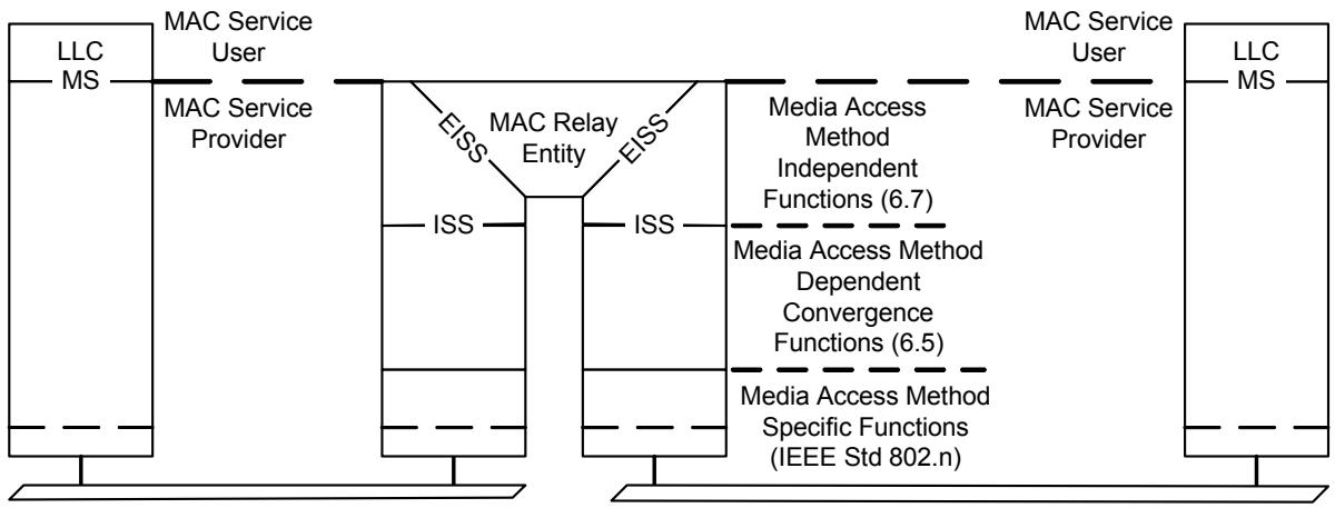
The position of a VLAN-aware Bridge's MAC Relay Entity (8.2) within the MAC Sublayer is shown in Figure 6-1.
NOTE—The notation “IEEE Std 802.n” in this figure indicates that the specifications for these functions can be found in the relevant standard for the media access method concerned; for example, n would be 3 (IEEE Std 802.3) in the case of Ethernet.
Figure 6-1—Internal organization of the MAC sublayer
The MAC Sublayer comprises:
a) Media access method specific functions $^{13}$ that realize transmission and reception of MAC Protocol Data Units (MPDUs);
b) Media access method dependent convergence functions that use item a) to provide a media access method independent service;
c) Media access method independent functions that use a media independent service to provide the same or another media independent service.
A VLAN-aware Bridge's MAC Relay Entity forwards frames between the instances of the media independent Enhanced Internal Sublayer Service (EISS, 6.4). The EISS is provided by the functions specified in 6.7 using the media independent Internal Sublayer Service (6.4). The convergence functions that provide the ISS using the media specific functions for each IEEE 802 LAN MAC type are specified in 6.5.
The provisions of Clause 6 of IEEE Std 802.1D apply to this standard, with the additions and modification defined in this clause.
6.1 Support of the MAC service
The MAC Service (MS) provided to end stations attached to a Virtual Bridged Local Area Network is the (unconfirmed) connectionless mode MAC Service defined in ISO/IEC 15802-1. The MAC Service is defined as an abstraction of the features common to a number of specific MAC Services; it describes the transfer of user data between source and destination end stations, via MA-UNITDATA request primitives and corresponding MA-UNITDATA indication primitives issued at MAC Service access points. Each MA-UNITDATA request and indication primitive has four parameters: Destination Address, Source Address, MAC Service data unit (MSDU), and Priority.
The style of Bridge operation maximizes the availability of the MAC Service to end stations and assists in the maintenance of the network. It is therefore desirable that Bridges be capable of being configured in the network:
a) So as to provide redundant paths between end stations to enable the network to continue to provide the Service in the event of component failure (of Bridge or LAN).
b) So that the paths supported between end stations are predictable and configurable given the availability of network components.
The operation of Bridges supports the provision of the MAC Service only to devices that are authenticated and authorized for such use. Unauthorized devices may be denied access to the network, other than as necessary to support the protocol exchanges that are required by any authentication process that is supported.
NOTE—Authentication and authorization to access a LAN may be achieved by administrative or management mechanisms, or by means of an active authorization mechanism, such as is defined in IEEE Std 802.1X.
6.2 Preservation of the MAC service
The MAC Service offered by a network consisting of LANs interconnected by Bridges is similar to that offered by a single LAN (see 6.3).
a) Frames transmitted between end stations carry the MAC Addresses of the peer-end stations in their destination and source address fields, not an address of a Bridge. The Bridge relay is not directly addressed by communicating end stations.
b) The MAC Addresses of end stations are not restricted by the network's topology or configuration.
c) All MAC Addresses need to be unique within a VLAN, and within any set of VLANs for which filtering information is shared by a Bridge.
6.3 Quality of service maintenance
6.3.1 Service availability
Service availability is measured as that fraction of some total time during which the MAC Service is provided. The operation of a Bridge can increase or lower the service availability.
The service availability can be increased by automatic reconfiguration of the network in order to avoid the use of a failed component (e.g., repeater, cable, or connector) in the data path. The service availability can be lowered by failure of a Bridge, through denial of service by the Bridge, or through frame filtering by the Bridge. Changes in topology, caused by component failures, the addition or removal of components, or by administrative changes, are detected and signaled by the following means:
a) Physical detection of component failure and signaling of that failure by the Enhanced Internal Sublayer Service (6.6 and 6.7);
b) Detection of component failure through the operation of a spanning tree algorithm and protocol;
c) Explicit signaling of reconfiguration events through the operation of a spanning tree algorithm and protocol.
Automatic reconfiguration can be achieved rapidly on the detection of a physical topology change (see Clause 17 of IEEE Std 802.1D), thus minimizing any service denial that is caused by the reconfiguration.
A Bridge may deny service and discard frames (6.3.2) in order to preserve other aspects of the MAC Service (6.3.3 and 6.3.4) when automatic reconfiguration takes place. Service may be denied to end stations that do not benefit from the reconfiguration; hence, the service availability is lowered for those end stations. Bridges may filter frames in order to localize traffic in the network. Should an end station move, it may then be unable to receive frames from other end stations until the filtering information held by the Bridges is updated.
To minimize the effects of service denial caused by reconfiguration events, filtering information that has been dynamically learned can be modified when automatic reconfiguration takes place, or in preparation for future reconfiguration events (Clause 17 and 17.10 of IEEE Std 802.1D). However, filtering information that is statically configured cannot be modified in this way.
A Bridge may deny service and discard frames in order to prevent access to the network by devices that are not authorized for such access.
To maximize the service availability, no loss of service or delay in service provision should be caused by Bridges, except as a consequence of a failure, removal, or insertion of a network component; or as a consequence of the movement of an end station; or as a consequence of an attempt to perform unauthorized access. These events are regarded as extraordinary. The operation of any additional protocol necessary to maintain the quality of the MAC Service is thus limited to the configuration of the network and is independent of individual instances of service provision.
NOTE 1—This is true only in circumstances where admission control mechanisms are not present, i.e., where the Bridges provide a “best effort” service.
NOTE 2—The operation of management on the Bridge can result in the Bridge being reset, either as a result of a specific Bridge reset operation or as a consequence of manipulating the Bridge's configuration. From the point of view of service availability, resetting the Bridge is an extraordinary event that has a similar effect to physical removal of the Bridge from the network, followed by reinsertion of the Bridge into the network.
6.3.2 Frame loss
The MAC Service does not guarantee the delivery of Service Data Units. Frames transmitted by a source station arrive, uncorrupted, at the destination station with high probability. The operation of a Bridge introduces minimal additional frame loss.
A frame transmitted by a source station can fail to reach its destination station as a result of
a) Frame corruption during physical layer transmission or reception.
b) Frame discard by a Bridge because
1) It is unable to transmit the frame within some maximum period of time and, hence, must discard the frame to prevent the maximum frame lifetime (6.3.6) from being exceeded.
2) It is unable to continue to store the frame due to exhaustion of internal buffering capacity as frames continue to arrive at a rate in excess of that at which they can be transmitted.
3) The size of the service data unit carried by the frame exceeds the maximum supported by the MAC procedures employed on the LAN to which the frame is to be relayed.
4) Changes in the connected topology of the network necessitate frame discard for a limited period of time to maintain other aspects of Quality of Service (see 17.10 of IEEE Std 802.1D).
5) The device attached to the Port is not authorized for access to the network.
6) The configuration of Static Filtering Entries or Static VLAN Registration Entries in the Filtering Database (8.8.1, 8.8.2) disallows the forwarding of frames with particular destination addresses or VLAN classifications on specific Ports.
7) A flow metering algorithm (8.6.5) determines that discard is necessary.
NOTE—As Static Filtering Entries and Static VLAN Registration Entries are associated with particular Ports or combinations of Ports, there is a possibility that misconfiguration of such entries will lead to unintended frame discard during or following automatic reconfiguration of the network.
6.3.3 Frame misordering
The MAC Service (9.2 of ISO/IEC 15802-1) permits a negligible rate of reordering of frames with a given priority for a given combination of destination address and source address, transmitted on a given VLAN. MA_UNITDATA.indication service primitives corresponding to MA_UNITDATA.request primitives, with the same requested priority and for the same combination of VLAN classification, destination address, and source address, are received in the same order as the request primitives were processed.
NOTE 1—The operation of the Forwarding Process in Bridges (8.6) is such that the frame-ordering characteristics of the MAC Service are preserved.
Where Bridges in a network are capable of connecting the individual MACs in such a way that multiple paths between any source station–destination station pairs exist, the operation of a protocol is required to ensure that a single path is used.
NOTE 2—Where STP is in use (see Clause 8 of IEEE Std 802.1D, 1998 Edition), frame misordering cannot occur during normal operation. Where RSTP is in use (see Clause 17 of IEEE Std 802.1D), there is an increased probability that frames that are in transit through the network will be misordered, because a Bridge can buffer frames awaiting transmission through its Ports. The probability of misordering occurring as a result of such an event is dependent on implementation choices and is associated with Spanning Tree reconfiguration events. Some known LAN protocols, for example, LLC Type 2, are sensitive to frame duplication; in order to allow Bridges that support RSTP to be used in environments where sensitive protocols are in use, the forceVersion parameter (17.16.1 of IEEE Std 802.1D) can be used to force a Bridge that supports RSTP to operate in an STP-compatible manner. A more detailed discussion of misordering in RSTP can be found in F.2.4 of IEEE Std 802.1D.
6.3.4 Frame duplication
The MAC Service (9.2 of ISO/IEC 15802-1) permits a negligible rate of duplication of frames. The operation of Bridges introduces a negligible rate of duplication of user data frames.
The potential for frame duplication in a network arises through the possibility of duplication of received frames on subsequent transmission within a Bridge, or through the possibility of multiple paths between source and destination end stations.
Where Bridges in a network are capable of connecting the individual MACs in such a way that multiple paths between any source station–destination station pairs exist, the operation of a protocol is required to ensure that a single path is used.
NOTE—Where RSTP is in use (see Clause 17 of IEEE Std 802.1D), there is an increased probability that a Spanning Tree reconfiguration event can cause frames that are in transit through the network to be duplicated, because a Bridge can buffer frames awaiting transmission through its Ports. As the probability of duplication occurring as a result of such an event is small, and the frequency of Spanning Tree reconfiguration events is also small, the degradation of the properties of the MAC service caused by this source of frame duplication is considered to be negligible. A more detailed discussion of frame duplication in RSTP can be found in F.2.4 of IEEE Std 802.1D.
6.3.5 Transit delay
The MAC Service introduces a frame transit delay that is dependent on the particular media and MAC method employed. Frame transit delay is the elapsed time between an MA_UNITDATA.request primitive and the corresponding MA_UNITDATA.indication primitive. Elapsed time values are calculated only on Service Data Units that are successfully transferred.
Since the MAC Service is provided at an abstract interface within an end station, it is not possible to specify precisely the total frame transit delay. It is, however, possible to measure those components of delay associated with media access and with transmission and reception; and the transit delay introduced by an intermediate system, in this case a Bridge, can be measured.
The minimum additional transit delay introduced by a Bridge is the time taken to receive a frame plus that taken to access the media onto which the frame is to be relayed. Note that the frame is completely received before it is relayed as the Frame Check Sequence (FCS) is to be calculated and the frame discarded if in error.
6.3.6 Frame lifetime
The MAC Service ensures that an upper bound to the transit delay is experienced for a particular instance of communication. This maximum frame lifetime is necessary to ensure the correct operation of higher layer protocols. The additional transit delay introduced by a Bridge is discussed in 6.3.5.
To enforce the maximum frame lifetime, a Bridge may be required to discard frames. Since the information provided by the MAC Sublayer to a Bridge does not include the transit delay already experienced by any particular frame, Bridges discard frames to enforce a maximum delay in each Bridge.
The value of the maximum bridge transit delay is based on both the maximum delays imposed by all Bridges in the network and the desired maximum frame lifetime. A recommended and an absolute maximum value are specified in Table 7-3 of IEEE Std 802.1D.
6.3.7 Undetected frame error rate
The MAC Service introduces a very low undetected frame error rate in transmitted frames. Undetected errors are protected against by the use of an FCS that is appended to the frame by the MAC Sublayer of the source station prior to transmission, and checked by the destination station on reception.
The FCS calculated for a given service data unit is dependent on the MAC method employed. It is therefore necessary to recalculate the FCS within a Bridge providing a relay function between IEEE 802 LAN MACs of dissimilar types if differences in the method of calculation and/or the coverage of the FCS, or changes to the data that is within the coverage of the FCS, would lead to a different FCS being calculated for the service data unit by the two MAC methods. This introduces the possibility of additional undetected errors arising from the operation of a Bridge. For frames relayed between LANs of the same MAC type, the Bridge shall not introduce an undetected frame error rate greater than that which would have been achieved by preserving the FCS.
NOTE—Application of the techniques described in Annex F of IEEE Std 802.1D allows an implementation to achieve an arbitrarily small increase in undetected frame error rate, even in cases where the data that is within the coverage of the FCS is changed. As a maintenance activity on this standard, revision of the wording of this requirement will be initiated, with a view to placing a quantitative limit on the increase in undetected frame error rate that is acceptable in a conformant implementation.
6.3.8 Maximum Service Data Unit Size
The Maximum Service Data Unit Size that can be supported by an IEEE 802 LAN varies with the MAC method and its associated parameters (speed, electrical characteristics, etc.). It may be constrained by the owner of the LAN. The Maximum Service Data Unit Size supported by a Bridge between two LANs is the smaller of that supported by the LANs. No attempt is made by a Bridge to relay a frame to a LAN that does not support the size of Service Data Unit conveyed by that frame.
6.3.9 Priority
The MAC Service includes priority as a Quality of Service parameter. MA_UNITDATA.request primitives with a high priority may be given precedence over other request primitives made at the same station, or at other stations attached to the same LAN and can give rise to earlier MA_UNITDATA.indication primitives.
The MAC Sublayer maps the requested priority onto the priorities supported by the individual MAC method. The requested priority may be conveyed to the destination station.
The transmission delay experienced by a frame in a Bridge can be managed by associating a priority with the frame.
The transmission delay comprises
a) A queuing delay until the frame becomes first in line for transmission on the Port, in accordance with the procedure for selecting frames for transmission described in 8.6.8;
b) The access delay for transmission of the frame.
Queuing delays can be managed using priority. Access delays can be managed using priority in MAC methods that support more than one priority.
The priority associated with a frame can be signaled by means of the priority signaling mechanisms inherent in some IEEE 802 LAN MAC types. Since not all IEEE 802 LAN MAC types are able to signal the priority associated with a frame, VLAN-aware Bridges regenerate priority based on a combination of signaled information and configuration information held in the Bridge.
The Bridge maps the priority onto one or more traffic classes; Bridges that support more than one traffic class are able to support expedited classes of traffic. The Forwarding Process, 8.6, describes the use of priority and traffic classes in Bridges. Given the constraints placed on frame misordering in a Bridge, as expressed in 6.3.3, the mappings of priority and traffic class are static.
NOTE 1—The term “Traffic Class,” as used in this standard, is used only in the context of the operation of the priority handling and queueing functions of the Forwarding Process, as described in 8.6. Any other meanings attached to this term in other contexts do not apply to the use of the term in this standard.
The ability to signal priority in IEEE 802 LANs, coupled with a consistent approach to the mapping of priority to traffic classes, and of priority to the priority requested from the individual LAN or supporting service, allows consistent use of priority information to be made, according to the capabilities of the Bridges and MAC methods that are involved in the transmission path.
NOTE 2—This standard defines a frame format and associated procedures that can be used to carry priority information across LAN MAC types that are not able to signal priority.
Under normal circumstances, priority is not modified in transit through the relay function of a Bridge; however, there may be some circumstances where it is desirable for management purposes to control how priority is propagated. The Priority Regeneration Table (Table 6-3) provides the ability to map incoming priority values on a per-Port basis, under management control. In its default state, this table provides an identity mapping from priority values to Regenerated priority values; i.e., by default, the Regenerated priority is identical to the incoming priority.
6.3.10 Throughput
The total throughput provided by a network can be significantly greater than that provided by an equivalent single LAN. Bridges may localize traffic within the network by filtering frames. Filtering services available in bridged networks are described in 6.6 of IEEE Std 802.1D.
The throughput between end stations on individual LANs, communicating through a Bridge, can be lowered by frame discard in the Bridge due to the inability to transmit at the required rate on the LAN forming the path to the destination for an extended period.
6.4 Internal Sublayer Service
The Internal Sublayer Service (ISS) augments the specification of the MAC Service (ISO/IEC 15802-1) with elements necessary to the performance of the relay function. Within an end station, these additional elements are considered to be either below the MAC Service boundary, and pertinent only to the operation of the service provider; or local matters not forming part of the peer-to-peer nature of the MAC Service. The ISS excludes MAC-specific features and procedures whose operation is confined to an individual LAN.
NOTE—No new service primitives are defined. The frame_check_sequence is added to list of parameters associated with the MA_UNITDATA.request and MA_UNITDATA.indication primitives.
6.4.1 Service primitives and parameters
The ISS is specified by two unit-data primitives, an M_UNITDATA.indication and an M_UNITDATA.request, together with the parameters of those primitives. Each M_UNITDATA indication corresponds to the receipt of an error-free MAC frame from a LAN. A data request primitive is invoked to transmit a frame to an individual LAN.
NOTE 1—Detailed specifications of error conditions in received frames are contained in the relevant MAC standards; for example, FCS errors, length errors, and non-integral number of octets.
  M_UNITDATA.indication (
  destination_address,
  source_address,
  mac_service_data_unit,
  priority,
  frame_check_sequence
  )
  M_UNITDATA.request (
  destination_address,
  source_address,
  mac_service_data_unit,
  priority,
  frame_check_sequence
  )
The destination_address parameter is the address of an individual MAC entity or a group of MAC entities. The source_address parameter is the individual address of the source MAC entity. The mac_service_data_unit parameter is the service user data. The default priority value is 0. Values 1 through 7 form an ordered sequence of user_priorities, with 1 being the lowest value and 7 the highest.
The frame_check_sequence parameter is explicitly provided with the M_UNITDATA.indication so that it can be used in a related M_UNITDATA.request. The parameter comprises the FCS value and sufficient information to determine whether the FCS value can be used. If the frame_check_sequence parameter is provided with an M_UNITDATA.request and the receiving and the transmitting service providers
a) Use the same algorithm to determine the FCS; and
b) Apply that algorithm to the same fields of the frame, i.e., the FCS coverage is the same; and
c) The data that is within the coverage of the FCS remains the same;
the transmitting service provider should use the supplied FCS value (6.3.7, 6.6).
NOTE 2—There are two possibilities for recreating a valid FCS. The first is to generate a new FCS by algorithmically modifying the received FCS, based on knowledge of the FCS algorithm and the transformations that the frame has undergone between reception and transmission. The second is to rely on the normal MAC procedures to recalculate the FCS for the outgoing frame. The former approach can be preferable in terms of its ability to protect against increased levels of undetected frame errors. Annex F of IEEE Std 802.1D discusses these possibilities in more detail. The frame_check_sequence parameter of the Enhanced Internal Sublayer Service (6.6) is able to signal the validity, or otherwise, of the FCS; an unspecified value in this parameter in a data request indicates to the transmitting MAC that the received FCS is no longer valid, and the FCS must therefore be recalculated.
The identification of the LAN from which particular frames are received is a local matter and is not expressed as a parameter of the service primitive.
NOTE 3—The ISS specification in this standard differs from that in IEEE Std 802.1D as it omits the frame_type and access_priority parameters. The frame_type is not required as the receipt of a frame other than a user data frame does not cause a data indication, nor are such frames transmitted by the media independent bridge functions. The mapping of the ISS to particular access methods specified by this standard includes derivation of the access_priority parameter (for those media that require it) from the ISS priority parameter.
6.4.2 Status parameters
The Internal Sublayer Service also makes available status parameters that reflect the operational state and administrative controls over each instance of the service provided.
The MAC_Enabled parameter is TRUE if use of the service is permitted; and is otherwise FALSE. The value of this parameter is determined by administrative controls specific to the entity providing the service, as specified in 6.5.
The MAC_Operational parameter is TRUE if the entity providing the service is capable of transmitting and receiving frames and its use is permitted by management, i.e., MAC_Enabled is also TRUE. Its value is otherwise FALSE. The value of this parameter is determined by the specific MAC procedures, as specified in 6.5.
NOTE—These status parameters provide a common approach across MACs for handling the fact that:
a) A MAC can inherently be working or not;
b) If the MAC is working, its operational state can be administratively overridden.
6.4.3 Point-to-point parameters
The Internal Sublayer Service also makes available status parameters that reflect the point-to-point status of each instance of the service provided and provide administrative control over the use of that information.
If the operPointToPointMAC parameter is TRUE, the service is used as if it provides connectivity to at most one other system; if FALSE, the service is used as if it can provide connectivity to a number of systems.
The adminPointToPointMAC parameter can take one of three values. If it is
a) ForceTrue, operPointToPointMAC shall be TRUE, regardless of any indications to the contrary generated by the service providing entity.
b) ForceFalse, operPointToPointMAC shall be FALSE.
c) Auto, operPointToPointMAC is determined by the service providing entity, as specified in 6.5.
The value of operPointToPointMAC is determined dynamically; i.e., it is re-evaluated whenever adminPointToPointMAC or the status of the service providing entity changes.
6.5 Support of the Internal Sublayer Service by specific MAC procedures
This subclause specifies support of the Internal Sublayer Service by MAC Entities that use specific IEEE 802 media access methods, including the mapping to the MAC protocol and procedures for each access method, and the encoding of the parameters of the service in MAC frames. The mapping is specified by reference to the IEEE 802 standards that specify each access method. The mapping draws attention to any special responsibilities of Bridges attached to LANs of that type. MAC control frames, typically frames that control some aspect of the operation of the MAC, i.e., frames that do not convey MAC user data, do not give rise to ISS data indications and are therefore not forwarded by a Bridge to any LAN other than that on which they originated.
Each MAC Entity examines all frames received on the LAN to which it is attached. All error-free received user data frames give rise to M_UNITDATA indication primitives. A frame that is in error, as defined by the relevant MAC specification, is discarded by the MAC Entity without giving rise to any M_UNITDATA indication.
Support of the ISS by the CSMA/CD access method is specified in 6.5 of IEEE Std 802.1D as amended by 6.5.1 of this standard.
Support of the ISS by the Wireless LAN (IEEE Std 802.11) access method is specified in 6.5 of IEEE Std 802.1D.
Support of the ISS by the Token Ring (IEEE Std 802.5) access method is specified in 4.1.13.2 of IEEE Std 802.5, with the following additions:
a) Following an M_UNITDATA.request, the priority parameter referenced by that clause shall be set equal to the value of the priority parameter of the ISS as specified in this standard. The column marked “8802-5 (default)” in Table 6-1 should be used to derive the access priority from the priority, but the column marked “8802-5 (alternate)” may be used for backwards compatibility with equipment manufactured in accordance with IEEE Std 802.1D, 1993 Edition. The use of this alternate mapping reduces the number of available access priority values to three. The frame type of each frame resulting from an M_UNITDATA.request shall be LLC, and the receipt of frames of other types shall not result in an M_UNITDATA.indication.
b) Following receipt of a frame, the priority parameter signaled in the corresponding M_UNITDATA.indication shall be regenerated from the priority specified in 4.1.13.2 of IEEE Std 802.5 using a Priority Regeneration Table for the MAC instance. This specifies the regenerated priority for each of the eight possible received values (0 through 7). Table 6-2 defines default values. If these are modified by management, the value of the table entries may be independently set for each MAC instance and value of received priority, and may use the full range of values in the parameter ranges specified.
Table 6-1—FDDI and Token Ring access priorities
<table><tr><td rowspan="2">priority</td><td colspan="3">access priority</td></tr><tr><td>8802-5 (default)</td><td>8802-5 (alternate)</td><td>FDDI</td></tr><tr><td>0</td><td>0</td><td>4</td><td>0</td></tr><tr><td>1</td><td>1</td><td>4</td><td>1</td></tr><tr><td>2</td><td>2</td><td>4</td><td>2</td></tr><tr><td>3</td><td>3</td><td>4</td><td>3</td></tr><tr><td>4</td><td>4</td><td>4</td><td>4</td></tr><tr><td>5</td><td>5</td><td>5</td><td>5</td></tr><tr><td>6</td><td>6</td><td>6</td><td>6</td></tr><tr><td>7</td><td>6</td><td>6</td><td>6</td></tr></table>
NOTE—It is important that the regeneration and mapping of priority be consistent with the end-to-end significance of that priority in the network. Within a given Bridge, the values chosen for the Priority Regeneration Table for a given Port should be consistent with the priority to be associated with traffic received through that Port across the rest of the network, and should generate appropriate access priority values for each media access method on transmission.
Table 6-2—FDDI and Token Ring priority regeneration
<table><tr><td>Received priority</td><td>Default regenerated priority</td><td>Range</td></tr><tr><td>0</td><td>0</td><td>0–7</td></tr><tr><td>1</td><td>1</td><td>0–7</td></tr><tr><td>2</td><td>2</td><td>0–7</td></tr><tr><td>3</td><td>3</td><td>0–7</td></tr><tr><td>4</td><td>4</td><td>0–7</td></tr><tr><td>5</td><td>5</td><td>0-7</td></tr><tr><td>6</td><td>6</td><td>0–7</td></tr><tr><td>7</td><td>7</td><td>0–7</td></tr></table>
Support of the ISS by the FDDI access methods is specified in 6.5 of IEEE Std 802.1D. The priority parameter referenced by that clause shall be set equal to the value of the priority parameter of the ISS as specified in this standard. The column marked “FDDI” in Table 6-1 should be used to derive the access priority from the priority. A Priority Regeneration Table for the MAC instance shall be used to determine the priority parameter of each M_UNITDATA.indication as specified above for Token Ring.
6.5.1 Support of the Internal Sublayer Service by IEEE Std 802.3 (CSMA/CD)
On receipt of an M_UNITDATA.request primitive that represents a tagged frame, the implementation is permitted to adopt either of the following approaches with regard to the operation of Transmit Data Encapsulation for frames whose length would, using the procedure as described, be less than 68 octets:
a) Use the procedure as described in 6.5.1 of IEEE Std 802.1D. This procedure can result in tagged frames of less than 68 octets (but at least 64 octets) being transmitted; or
b) Include additional octets before the FCS field in order for the transmitted frame length for such frames to be 68 octets. This procedure results in a minimum tagged frame length of 68 octets.
When a tagged frame of less than 68 octets in length is received on a CSMA/CD LAN segment, and is forwarded as an untagged frame, the provisions of 6.5.1 of IEEE Std 802.1D, result in additional octets being included before the FCS field on transmission in order that the transmitted frame length meets the minimum frame size requirements of 3.2.7 in IEEE Std 802.3.
6.6 Enhanced Internal Sublayer Service
The EISS is derived from the ISS (see 6.4) by augmenting that specification with elements necessary to the operation of the tagging and untagging functions of a VLAN-aware Bridge (3.41). Within the attached end station, these elements can be considered to be either below the MAC Service boundary, and pertinent only to the operation of the service provider; or local matters not forming part of the peer-to-peer nature of the MAC Service.
The EISS provides the same service status and point-to-point parameters as the ISS (6.4.2, 6.4.3).
6.6.1 Service primitives
The unit-data primitives that define this service are
  EM_UNITDATA.indication (
  destination_address,
  source_address,
  mac_service_data_unit,
  priority,
  vlan_identifier,
  frame_check_sequence,
  canonical_format_indicator,
  rif_information (optional)
  )
  EM_UNITDATA.request (
  destination_address,
  source_address,
  mac_service_data_unit,
  priority,
  vlan_identifier,
  frame_check_sequence,
  canonical_format_indicator,
  rif_information (optional)
  )
The destination_address, source_address, mac_service_data_unit, priority, and frame_check_sequence parameters are as defined for the ISS.
The vlan_identifier parameter carries the VLAN identifier (VID).
The canonical_format_indicator parameter indicates whether embedded MAC Addresses carried in the mac_service_data_unit parameter are in Canonical format or Non-canonical format. The value False indicates Non-canonical format. The value True indicates Canonical format.
NOTE—The meanings of the terms “Canonical format” and “Non-canonical format” are discussed in IEEE Std 802.
The rif_information parameter is present if a tag header containing a Routing Information Field (RIF) is present (indication primitive) or requested (request primitive). Its value is equal to the value of the RIF.
6.6.2 Status parameters
The EISS also makes available the MAC_Enabled and MAC_Operational status parameters that reflect the operational state and administrative controls over each instance of the service provided. The values of these parameters are mapped directly from the values made available by the ISS (6.4.2).
6.6.3 Point-to-point parameters
The EISS also makes available the operPointToPointMAC and adminPointToPointMAC status parameters that reflect the point-to-point status of each instance of the service provided and provide administrative control over the use of that information. The values of these parameters are mapped directly from the values made available by the ISS (6.4.3).
6.7 Support of the EISS
The EISS is supported by tagging and detagging functions that in turn use the ISS (6.4, 6.5). Any given instance of the EISS shall be supported by using the VLAN tag type specified in 9.5. Each Bridge Port shall support the following parameters for use by these functions:
a) an Acceptable Frame Types parameter with at least one of the following values:
1) Admit Only VLAN-tagged frames;
2) Admit Only Untagged and Priority-tagged frames;
3) Admit All frames.
b) a PVID parameter for port-based VLAN classification;
and may support the following parameter:
c) a VID Set for port-and-protocol-based classification (6.8).
All three values for Acceptable Frame Types may be supported; if so, they shall be configurable using the management operations defined in Clause 12, and the default shall be Admit All Frames. A frame is treated as Untagged if the initial octets of the mac_service_data_unit parameter do not contain a VLAN tag of the type used to support the EISS (9.5), as Priority-tagged if the value contained in the VID field of the VLAN tag is zero, and as VLAN-tagged if the value is non-zero.
The PVID and VID Set shall contain valid VID values (Table 9-2) and may be configured by management. If they have not been explicitly configured, the PVID shall assume the value of the default PVID defined in Table 9-2 and the VID Set shall be empty.
NOTE—The default behavior of a Bridge that supports port-and-protocol-based classification is the same as that of a Bridge that supports only port-based classification, since all the Protocol Group Identifiers in the VID Set for each Port assign the same VID as the PVID.
6.7.1 Data indications
On receipt of an M_UNITDATA.indication primitive from the Internal Sublayer Service, the received frame is discarded if:
a) The initial octets of the mac_service_data_unit do not contain a valid VLAN tag header (9.3) of the type used to support the EISS (9.5), and the Acceptable Frame Types is Admit Only VLAN-tagged frames; or,
b) The initial octets of the mac_service_data_unit do not contain a valid VLAN tag header (9.3) of the type used to support the EISS (9.5), and
1) The VID value is FFF, reserved in Table 9-2 for future implementation use; or
2) The VID value is 000 (indicating priority-tagged), and the Acceptable Frame Types is Admit Only VLAN-tagged frames; or
3) The VID value is in the range 001-FFE, and the Acceptable Frame Types is Admit Only Untagged and Priority-tagged frames.
Otherwise an EM_UNITDATA.indication primitive is invoked, with parameter values determined as follows:
The destination_address, source_address, and frame_check_sequence parameters carry values equal to the corresponding parameters in the received data indication.
NOTE 1—The frame_check_sequence parameter of the data indication carries the FCS value contained in the received frame. The original FCS associated with a frame is invalidated if there are changes to any fields of the frame, if fields are added or removed, or if bit ordering or other aspects of the frame encoding have changed. An invalid FCS is signaled in the E-ISS by an unspecified value in the frame_check_sequence parameter of the data request primitive. This signals the need for the FCS to be regenerated according to the normal procedures for the transmitting MAC. The options for regenerating the FCS under these circumstances are discussed in Annex F of IEEE Std 802.1D.
The value of the mac_service_data_unit parameter is as follows:
a) If the frame is tagged, then the value used is equal to the value of the received mac_service_data_unit following removal of the tag header.
b) Otherwise, the value used is equal to the value of the received mac_service_data_unit.
The value of the vlan_identifier parameter is as follows:
c) The value contained in the VID field, if the frame is VLAN-tagged;
d) The value of the PVID for the Port, if the frame is untagged or Priority-tagged and port-and-protocol VLAN classification is not implemented;
e) As determined by port-and-protocol-based VLAN classification (6.8) if that capability is implemented and the frame is untagged or Priority-tagged.
The value of the priority parameter is determined as follows:
f) The value of the priority parameter is regenerated from the received priority, as specified in 6.7.3.
The value of the canonical_format_indicator parameter is determined as follows:
g) If the frame is tagged, then the value is as specified in Clause 9.
h) Otherwise, if the MAC entity that received the data indication was an ISO/IEC 8802-5 Token Ring MAC, then the parameter carries the value False.
i) Otherwise, the parameter carries the value True.
The value of the rif_information parameter is determined as follows:
j) If the frame is tagged, then the value is as specified in Clause 9.
k) Otherwise, the parameter is not present.
NOTE 2—This field can be present only in tag headers received using IEEE Std 802.3/Ethernet or transparent FDDI MACs. The presence of one or more route descriptors indicates that there is source-routing information present in the received frame.
6.7.2 Data requests
On invocation of an EM_UNITDATA.request primitive by a user of the E-ISS, an M-UNITDATA.request primitive is invoked, with parameter values as follows:
The destination_address, source_address, and priority parameters carry values equal to the corresponding parameters in the received data request.
Unless the Bridge Port is a member of the untagged set (8.8.2) for the VLAN identified by the vlan_identifier parameter, then a tag header, formatted as necessary for the destination MAC type, is inserted as the initial octets of the mac_service_data_unit parameter. The values of the vlan_identifier, priority, canonical_format_indicator, and rif_information (if present) parameters are used to determine the contents of the tag header, in accordance with Clause 9.
If the Bridge Port is a member of the untagged set (8.8.2) for the VLAN identified by the vlan_identifier parameter, no tag header is inserted.
The remaining octets of the mac_service_data_unit parameter are those accompanying the EISS-request. If the data request is a consequence of relaying a frame and the MAC type of the Port differs from that used to receive the frame, they are modified, if necessary, in accordance with the procedures described in ISO/IEC 11802-5, IETF RFC 1042, and IETF RFC 1390. If the canonical_format_indicator parameter indicates that the mac_service_data_unit may contain embedded MAC Addresses in a format inappropriate to the destination MAC type, and no tag header is to be inserted, then the Bridge shall either
a) Convert any embedded MAC Addresses in the mac_service_data_unit to the format appropriate to the destination MAC type; or
b) Discard the EISS data request without issuing a corresponding ISS data request.
The value of the frame_check_sequence parameter is determined as follows:
c) If the frame_check_sequence parameter received in the data request is either unspecified or still carries a valid value, then that value is used.
d) Otherwise, the value used is either derived from the received FCS information by modification to take account of the conditions that have caused it to become invalid, or the unspecified value is used.
6.7.3 Regenerating priority
The priority of received frames is regenerated using priority information contained in the frame and the Priority Regeneration Table for the reception Port. For each reception Port, the Priority Regeneration Table has eight entries, corresponding to the eight possible values of priority (0 through 7). Each entry specifies, for the given value of received priority, the corresponding regenerated value.
For untagged frames, the priority parameter signaled in the corresponding M_UNITDATA.indication is taken to be the received priority. For tagged frames, the priority signaled in the PCP field of the tag header is taken to be the received priority.
NOTE 1—IEEE 802 LAN technologies signal a maximum of eight priority values. Annex G further explains the use of priority values and how they map to traffic classes.
Table 6-3 specifies default regenerated priority values for each of the eight possible values of the received priority. These default values shall be used as the initial values of the corresponding entries of the Priority Regeneration Table for each Port.
The values in the Priority Regeneration Table may be modified by management, as described in Clause 12. If this capability is provided, the value of the table entries shall be independently settable for each reception Port and for each value of received priority, and the Bridge shall have the capability to use the full range of values in the parameter ranges specified in Table 6-3.
NOTE 2—The regeneration and mapping of priority within the Bridge should be consistent with the end-to-end significance of that priority across the rest of the Bridged Local Area Network. The regenerated priority value is used:
— Via the traffic class table (8.6.6) to determine the traffic class for a given outbound Port, and
— Via fixed, MAC type-specific mappings (6.5) to determine the access priority that will be used for certain media access methods.
Table 6-3—Priority regeneration
<table><tr><td>Received priority</td><td>Default regenerated priority</td><td>Range</td></tr><tr><td>0</td><td>0</td><td>0–7</td></tr><tr><td>1</td><td>1</td><td>0–7</td></tr><tr><td>2</td><td>2</td><td>0–7</td></tr><tr><td>3</td><td>3</td><td>0–7</td></tr><tr><td>4</td><td>4</td><td>0–7</td></tr><tr><td>5</td><td>5</td><td>0-7</td></tr><tr><td>6</td><td>6</td><td>0–7</td></tr><tr><td>7</td><td>7</td><td>0–7</td></tr></table>
6.8 Protocol VLAN classification
Each instance of the tagging and detagging functions that supports the EISS (6.7), and implements the optional port-and-protocol-based VLAN classification, shall implement a VID Set, each member of which associates values of a Protocol Group Identifier (6.8.2) with a VID. Each Untagged and Priority-tagged frame received is assigned a vlan_identifier equal to the VID Set value for the receiving Port and the Protocol Group Identifier selected by matching the received frame with a Protocol Template.
The detagged_frame_type parameter indicates the frame format. Its value is determined as follows:
a) If the frame is Untagged or Priority Tagged, this parameter is present and indicates the link-layer encapsulation format of the Detagged Frame. The Detagged Frame of an Untagged Frame is the frame itself. The Detagged Frame of a Tagged Frame or Priority Tagged Frame is the frame that results from untagging the frame in accordance with the frame format described in Clause 9. The value of detagged_frame_type is as follows:
1) Ethernet, if the Detagged Frame uses Type-encapsulated IEEE 802.3 format
2) RFC_1042, if the Detagged Frame is of the format specified by 10.5 in IEEE Std 802-2001 for the encoding of an IEEE 802.3 Type Field in an IEEE 802.2/SNAP header (this supersedes the original definition, which appeared in RFC 1042)
3) SNAP_8021H, if the Detagged Frame is of the format specified by IEEE Std 802.1H, 1997 Edition, for the encoding of an IEEE 802.3 Type Field in an IEEE 802.2/SNAP header
4) SNAP_Other, if the Detagged Frame contains an LLC UI PDU with DSAP and SSAP fields equal to the LLC address reserved for SNAP and the 5-octet SNAP Protocol Identifier (PID) value is not in either of the ranges used for RFC_1042 or SNAP_8021H above
5) LLC_Other, if the Detagged Frame contains both a DSAP and an SSAP address field in the positions specified by IEEE 802.2 Logical Link Control, but is not any of the formats described for LLC frames above
b) Else the parameter is not present.
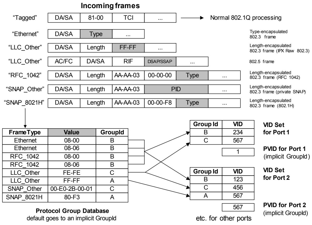
NOTE—The PID shown in this figure is a Protocol Identifier, as defined in 5.3 of IEEE Std 802. It is a 5-octet value consisting of a 3-octet OUI value followed by a 2-octet locally administered identifier.
Figure 6-2—Example of operation of port-and-protocol based classification
The EtherType value is present if the detagged_frame_type parameter is present and has the value Ethernet, RFC_1042, or SNAP_8021H. Its value is the value of the IEEE 802.3 Length/Type Field present in the Detagged Frame. $^{14}$ The value is determined as follows:
c) If the detagged_frame_type parameter is present and has the value Ethernet, RFC_1042, or SNAP_8021H, then this parameter is present and has the value of the IEEE 802.3 Type Field present in the Detagged Frame.
d) Else the parameter is not present.
The llc_saps parameter is present if the detagged_frame_type parameter is present and has the value LLC_Other. Its value is determined as follows:
e) If the detagged_frame_type parameter is present and has the value LLC_Other, then this parameter is present and its value is the pair of LLC IEEE 802.2 DSAP and SSAP address field values.
f) Else the parameter is not present.
NOTE 1—A frame that is encapsulated using values of hex FF/FF in the position where an LLC header is to be expected (as defined by IEEE Std 802.2, 1998 Edition) is known as a “Novell IPX Raw” encapsulation. Such frames do not conform to IEEE Std 802.2, 1998 Edition, in that they do not include some of the other required LLC fields. For the purposes of this standard, they are treated as LLC_Other, regardless of whether they are legal LLC frames.
NOTE 2—Bridges are not required, for the purposes of this standard, to completely verify the format of frames as meeting IEEE Std 802.2 or not. They are only required to recognize the DSAP and SSAP fields of such frames.
The snap_pid parameter is present if the detagged_frame_type parameter is present and has the value SNAP_Other. Its value is determined as follows:
g) If the detagged_frame_type parameter is present and has the value SNAP_Other, then the parameter is present and its value is the contents of the 5 octets following the LLC header, i.e., the PID field.
h) Else the parameter is not present.
6.8.1 Protocol Templates
In a Bridge that supports Port-and-Protocol-based VLAN classification, a Protocol Template is a tuple that specifies a protocol to be identified in received frames. A Protocol Template has one of the following formats:
a) A value “Ethernet” and a 16-bit IEEE 802.3 Type Field value
b) A value "RFC_1042" and a 16-bit IEEE 802.3 Type Field value
c) A value “SNAP_8021H” and a 16-bit IEEE 802.3 Type Field value
d) A value “SNAP_Other” and a 40-bit PID value
e) A value “LLC_Other” and a pair of IEEE 802.2 LSAP values: DSAP and SSAP
A Protocol Template matches a frame if
f) The frame's detagged_frame_type is Ethernet, the Protocol Template is of type Ethernet, and the frame's IEEE 802.3 Type Field is equal to the value of the IEEE 802.3 Type Field of the Protocol Template, or
g) The frame's detagged_frame_type is RFC_1042, the Protocol Template is of type RFC_1042 and the frame's IEEE 802.3 Type Field is equal to the IEEE 802.3 Type Field of the Protocol Template, or
h) The frame's detagged_frame_type is SNAP_8021H, the Protocol Template is of type SNAP_8021H, and the frame's IEEE 802.3 Type Field is equal to the IEEE 802.3 Type Field of the Protocol Template, or
i) The frame's detagged_frame_type is SNAP_Other, the Protocol Template is of type SNAP_Other, and the frame's snap_pid is equal to the PID of the Protocol Template, or
j) The frame's detagged_frame_type is LLC_Other, the Protocol Template is of type LLC_Other, and the frame's llc_saps matches the value of the DSAP and SSAP of the Protocol Template.
NOTE—If a port does not support Protocol Templates of the frame's detagged_frame_type, then no match will occur.
6.8.2 Protocol Group Identifiers
A Bridge that supports Port-and-Protocol-based VLAN classification shall support Protocol Group Identifiers.
A Protocol Group Identifier, shown as “Group Id” in Figure 6-2, designates a group of protocols that will be associated with one member of the VID Set of a Port. The association of protocols into groups is established by the contents of the Protocol Group Database, as described in 6.8.3. The identifier has scope only within a single bridge.
An implicit Protocol Group Identifier is assigned to frames that match none of the entries in the Protocol Group Database. Therefore, every incoming frame can be assigned to a Protocol Group Identifier.
6.8.3 Protocol Group Database
A Bridge that supports Port-and-Protocol-based VLAN classification shall support a single Protocol Group Database. The Protocol Group Database groups together a set of one or more Protocols by assigning them the same Protocol Group Identifier (6.8.2). Each entry of the Protocol Group Database comprises the following:
a) A Protocol Template
b) A Protocol Group Identifier
The Protocol Group Database specifies a mapping from Protocol Templates to Protocol Group Identifiers. If two entries of the Protocol Group Database contain different Protocol Group Identifiers, then their Protocol Templates must also be different.
The entries of the Protocol Group Database may be configured by management. A Bridge that supports Port-and-Protocol-based VLAN classification shall support at least one of the Protocol Template formats.
An implicit Protocol Group Database entry exists that matches all frames. This entry is invoked for frames that do not match the template of any of the other entries. It references an implicit Protocol Group Identifier that selects the PVID on each port. In this way, it is ensured that all incoming frames are matched by a Protocol Group Identifier and, hence, are assigned to a VID.
NOTE—If there are no entries in the Protocol Group Database, then the frame relay behavior of this Bridge is identical to the frame relay behavior of a Bridge having the same number of Ports that supports only Port-based VLAN classification.
7 Principles of network operation
This clause establishes the principles and a model of Virtual Bridged Local Area Network operation. It defines the context necessary for:
a) The operation of individual VLAN-aware Bridges (Clause 8);
b) Their participation in the Spanning Tree (Clause 8 of IEEE Std 802.1D, 1998 Edition), Rapid Spanning Tree (Clause 17 of IEEE Std 802.1D), or Multiple Spanning Tree Protocol (Clause 13);
c) The management of individual Bridges (Clause 12); and
d) The management of VLAN Topology (Clause 11)
to support, preserve, and maintain the quality of the MAC Service as discussed in Clause 6.
7.1 Network overview
The operation of a Virtual Bridged Local Area Network, the Bridges, and the LANs, that compose that network comprises:
a) A physical topology comprising LANs, Bridges, and Bridge Ports. Each Bridge Port attaches a LAN to a Bridge and is capable of providing bidirectional connectivity for MAC user data frames. Each LAN is connected to every other LAN by a Bridge and zero or more other LANs and Bridges.
b) Calculation of one or more active topologies, each a loop-free subset of the physical topology.
c) Rules for the classification of MAC user data frames that allow each Bridge to allocate, directly or indirectly, each frame to one and only one active topology.
d) Management control of the connectivity provided for differently classified data frames by the selected active topology.
e) Implicit or explicit configuration of end station location information, identifying LANs with attached end stations that need to receive user data frames with a given destination address.
f) Communication of end station location information to allow Bridges to restrict user data frames to LANs in the path provided to their destination(s) by the chosen active topology.
These elements and their interrelationships are illustrated in Figure 7-1.
NOTE 1—The physical and active topologies can be represented as bi-partite graphs. Bridges and LANs are nodes in these graphs (including LANs that are point-to-point links) and the Bridge Ports are edges.
NOTE 2—This standard applies the notion of a physical topology to media access control methods, like wireless, where there is no tangible physical connection between a Bridge and an attached LAN. A Bridge Port models this association just as for wired connectivity.
NOTE 3—Each of the active topologies [see item b)] does not necessarily span the entire network, but does span all those Bridges and LANs between which data frame connectivity is desired for frames allocated to that active topology.
NOTE 4—The destination addressing information associated with a MAC user data frame includes the VLAN classification of the frame [see item d)].
NOTE 5—Implicit configuration [see item d)], or recognition, of end station location includes observation of the source address of the user data frame transmitted by that station. The user data frame communicates that location information [see item e)] along the portion of the chosen active topology leading to the frame's destination(s).
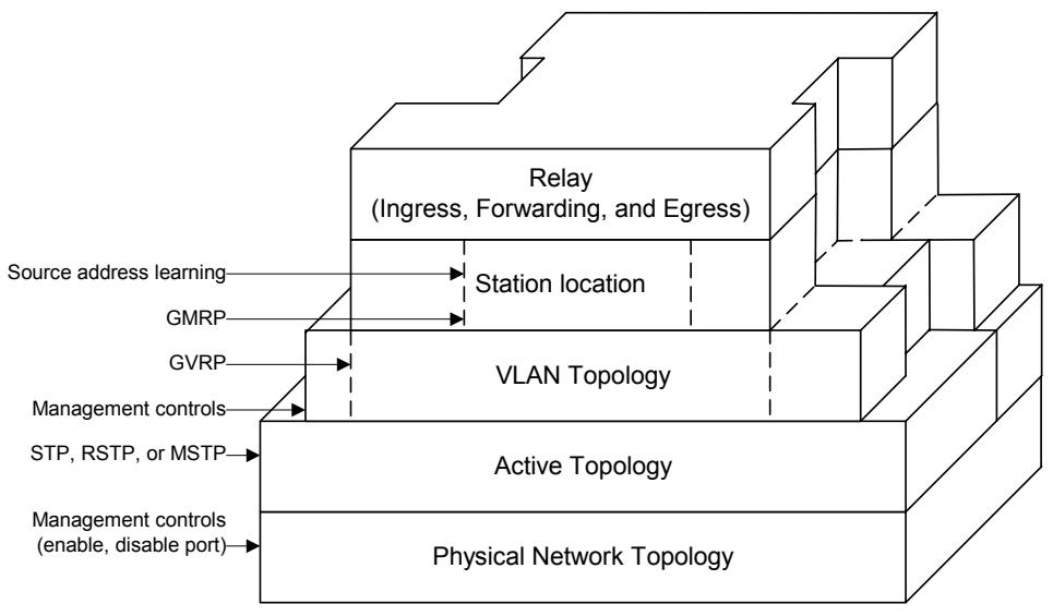
Figure 7-1—VLAN Bridging overview
7.2 Use of VLANs
Virtual Local Area Networks (VLANs) and their VLAN Identifiers (VIDs) provide a convenient and consistent network-wide reference for Bridges to:
a) Identify rules for the classification of user data frames into VLANs;
b) Effectively extend the source and destination MAC addresses, by treating frames and addressing information for different VLANs independently;
c) Identify and select from different active topologies;
d) Identify the configuration parameters that partition or restrict access from one part of the network to another.
Taken together these capabilities allow VLAN-aware Bridges to emulate a number of separately manageable, or virtual, Bridged Local Area Networks. A LAN segment that has been selected by network management to receive frames assigned to a given VLAN is said to form part of, belong to, or be a member of the VLAN. Similarly, end stations that are attached to those LAN segments and that can receive frames assigned to the VLAN are said to be attached to that VLAN.
NOTE—Separate control over the transmission and over the reception of frames to and from LAN segments and end stations is possible. To avoid ambiguity, VLAN membership is defined by reception.
Inclusion of the VID in VLAN-tagged frames guards against connectivity loops arising from differing classifications by different Bridges, and permits enhanced classification rules to be used by some Bridges, while others simply forward the previously classified frames.
The VLAN tag allows frames to carry priority information, even if the frame has not been classified as belonging to a particular VLAN.
7.3 VLAN topology
Each Bridge cooperates with others to operate a spanning tree protocol to calculate one or more loop-free, fully connected, active topologies. This calculation supports the quality of the MAC Service (Clause 6) and provides rapid recovery from network component failure, by using alternate physical connectivity, without requiring management intervention.
All user data frames classified as belonging to a given VLAN are constrained by the forwarding process of each Bridge to a single active topology. Each and every VLAN is thus associated with a spanning tree, although more than one VLAN can be associated with any given tree. Each VLAN may occupy the full extent of the active topology of its associated spanning tree or a connected subset of that active topology. The maximum extent of the connected subset may be bounded by management by explicitly excluding certain Bridge Ports from a VLAN's connectivity.
At any time the current extent of a VLAN can be further reduced from the maximum to include only those LAN segments that provide communication between attached devices, by the use of protocol that allows end stations to request and release services that use the VLAN. Such a protocol is specified in Clause 11. The dynamic determination of VLAN extent provides flexibility and bandwidth conservation, at the cost of network management complexity.
NOTE 1—Dynamic determination of VLAN extent is generally preferable to static configuration for bandwidth conservation, as the latter is error prone and can defeat potential alternate connectivity-requiring active management intervention to recover from network component failure.
NOTE 2—To accommodate end stations that do not participate in the GVRP protocol specified in Clause 11, management controls associated with each Bridge Port allow the Port to identify the attached LAN segment as connecting end stations that require services using specified VLANs.
7.4 Locating end stations
Functioning as a distributed system, Bridges within the current extent of a VLAN can, through explicit and or implicit cooperation, locate those LAN segments where an attached end station or end stations are intended to receive frames addressed to a specified individual address or group address. Bridges can thus reduce traffic by confining frames to the LAN segments where their transmission is necessary.
NOTE 1—Individually Bridges do not determine the precise location of end stations but merely determine which of their Bridge Ports need to forward frames toward the destination(s). For the system of Bridges this is sufficient to restrict frames to the paths necessary to reach the destination segments.
The multicast registration protocol (GMRP), specified in Clause 10 of IEEE Std 802.1D, allows end stations to advertise their presence and their desire to join (or leave) a multicast group in the context of a VLAN. The protocol communicates this information to other Bridges, using the VLAN and its active topology.
NOTE 2—To accommodate end stations that do not participate in GMRP, management controls associated with each Bridge Port allow the Port to identify the attached LAN segment as connecting end stations that are intended to receive specified group addresses. The continuous operation of GMRP and the propagation of location information through Bridges using the current active topology for the VLAN support multicast traffic reduction, while ensuring rapid restoration of multicast connectivity without management intervention if alternate connectivity is selected following network component failure.
Each end station implicitly advertises its attachment to a LAN segment and its individual MAC address whenever it transmits a frame. Bridges learn from the source address as they forward the frame along the active topology to its destination or destinations – or throughout the VLAN if the location of the destination or destinations is unknown. The learned information is stored in the Filtering Database used to filter frames on the basis of their destination addresses.
The Filtering Database architecture defined in this standard recognizes that
a) For some configurations, it is necessary to allow address information learned in one VLAN to be shared among a number of VLAN's. This is known as Shared VLAN Learning (3.29);
b) For some configurations, it is desirable to ensure that address information learned in one VLAN is not shared with other VLANs. This is known as Independent VLAN Learning (3.12);
c) For some configurations, it is immaterial as to whether learned information is shared between VLANs.
NOTE 1—Annex B discusses the need for Shared and Independent VLAN Learning and some related interoperability issues.
Shared VLAN Learning is achieved by including learned information from a number of VLANs in the same Filtering Database; Independent VLAN Learning is achieved by including information from each VLAN in distinct Filtering Databases.
NOTE 2—The actual Filtering Database specification specifies a single Filtering Database that, through the inclusion of VLAN identification information in each database entry, can model the existence of one or more distinct Filtering Databases.
Within a given network, there may be a combination of configuration requirements, so that individual Bridges may be called on to share learned information, or not share it, according to the requirements of particular VLANs or groups of VLANs. The Filtering Database structure that is defined in this standard allows both Shared and Independent VLAN Learning to be implemented within the same Bridge; i.e., allows learned information to be shared between those VLANs for which Shared VLAN Learning is necessary, while also allowing learned information not to be shared between those VLANs for which Independent VLAN Learning is necessary. The precise requirements for each VLAN with respect to sharing or independence of learned information (if any) are made known to Bridges by means of a set of VLAN Learning Constraints (8.8.7.2) and fixed allocations of VLANs to filtering databases (8.8.7.1), which may be configured into the Bridges by means of management operations. By analyzing the set of learning constraints and fixed allocations for the VLANs that are currently active, the Bridge can determine
d) How many independent Filtering Databases are required in order to meet the constraints;
e) For each VLAN, which Filtering Database it will feed any learned information into (and use learned information from).
The manner in which this mapping of VLANs onto Filtering Databases is achieved is defined in 8.8.7; the result is that each VLAN is associated with exactly one Filtering Database.
The most general application of the Filtering Database specification in this standard is a Bridge that can support M independent Filtering Databases and can map N VLANs onto each Filtering Database. Such a Bridge is known as an SVL/IVL Bridge (3.31).
The conformance requirements in this standard (5.3) recognize that Bridges will be implemented with differing capabilities in order to meet a wide range of application needs, and that the full generality of the SVL/IVL approach is not always either necessary or desirable, as observed in the discussion in Annex B. In a given conformant implementation, there may be restrictions placed on the number of Filtering Databases that can be supported and/or the number of VLANs that can be mapped onto each Filtering Database. The full spectrum of conformant Filtering Database implementations is therefore as follows:
f) The SVL/IVL Bridge, as described above. Such Bridges provide support for M Filtering Databases, with the ability to map N VLANs onto each one;
g) Support for a single Filtering Database only. MAC Address information that is learned in one VLAN can be used in filtering decisions taken relative to all other VLANs supported by the Bridge. Bridges that support a single Filtering Database are referred to as SVL Bridges;
h) Support for multiple Filtering Databases, but only a single VLAN can be mapped onto each Filtering Database. MAC Address information that is learned in one VLAN cannot be used in filtering decisions taken relative to any other VLAN. Bridges that support this mode of operation are referred to as IVL Bridges.
7.5 Ingress, forwarding, and egress rules
The relay function provided by each Bridge controls:
a) Classification of each received frame as belonging to one and only one VLAN, and discard or acceptance of the frame for further processing on the basis of that classification and the received frame format, which can be one of three possible types:
1) Untagged, and not explicitly identifying the frame as belonging to a particular VLAN;
2) Priority-tagged, i.e., including a tag header conveying explicit priority information but not identifying the frames as belonging to a specific VLAN;
3) VLAN-tagged, i.e., explicitly identifying the frames as belonging to a particular VLAN.
This aspect of relay implements the ingress rules.
b) Implementation of the decisions governing where each frame is to be forwarded as determined by the current extent of the VLAN topology (7.3), station location information (7.4), and the additional management controls specified in Clause 8. This aspect of relay implements the forwarding rules.
c) Queueing of frames for transmission through the selected Bridge Ports, management of the queued frames, selection of frames for transmission, and determination of the appropriate frame format type, VLAN-tagged or untagged. This aspect of relay implements the egress rules.
The structuring of the relay functionality into the implementation of ingress, forwarding, and egress rules constitutes a generic approach to the provision of VLAN functionality. All VLAN-aware Bridges can correctly forward received frames that are already VLAN-tagged. These are classified as belonging to the VLAN identified by the VID in the tag header. All VLAN-aware Bridges can also classify untagged and priority-tagged frames received on any given port as belonging to a specified VLAN. In addition to this default Port-based ingress classification, this standard specifies an optional Port-and-Protocol-based classification.
The classification of untagged and priority-tagged frames, and the addition or removal of tag headers, is part of the relay functionality of a VLAN-aware Bridge and is only performed on frames that can be forwarded through other Bridge Ports.
Frames that carry control information to determine the active topology and current extent of each VLAN, i.e., spanning tree and GVRP BPDUs, and frames from other link constrained protocols, such as EAPOL and LLDP, are not forwarded. Permanently configured static entries in the filtering database (8.2, 8.3, and 8.12) ensure that such frames are discarded by the Forwarding Process (8.6).
NOTE—GARP PDUs destined for any GARP application are forwarded or filtered depending on whether the application concerned is supported by the bridge, as specified in 8.12.
The forwarding rules specified for VLAN-tagged frames facilitate the interoperation of bridges conformant to this standard with end stations that directly support attachment of MAC service users to VLANs by transmitting VLAN-tagged frames, and with Bridges that are capable of additional proprietary ingress classification methods.
Frames transmitted on a given LAN segment by a VLAN-aware Bridge for a given VLAN shall be either
d) All untagged; or
e) All VLAN tagged with the same VID.
8 Principles of bridge operation
This clause
a) Explains the principal elements of VLAN-aware Bridge operation and lists the supporting functions.
b) Establishes a Bridge architecture that governs the provision of these functions.
c) Provides a model of Bridge operation in terms of processes and entities that support the functions.
d) Details the addressing requirements in a Bridged Local Area Network.
e) Specifies the addressing of Entities in a Bridge.
NOTE—The provisions of this clause subsume the provisions of Clause 7 of IEEE Std 802.1D.
8.1 Bridge operation
The principal elements of Bridge operation are
a) Relay and filtering of frames (8.1.1).
b) Maintenance of the information required to make frame filtering and relaying decisions (8.1.2).
c) Management of the above (Clause 12).
8.1.1 Relay
A MAC Bridge relays individual MAC user data frames between the separate MACs of the bridged LANs connected to its Ports. The functions that support relaying of frames and maintain the Quality of Service are
a) Frame reception (8.5).
b) Discard on received frame in error (6.3.2).
c) Discard of frames that do not carry user data (6.5).
d) Priority decoding from a VLAN TAG, if present, and regeneration of priority, if required (6.7).
e) Classification of each received frame to a particular VLAN (6.7).
f) Frame discard to support management control over the active topology of each VLAN (8.6.2).
g) Frame discard to suppress loops in the physical topology of the network (8.6.1).
h) Frame discard following the application of filtering information (8.6.3).
i) Metering of frames, potentially discarding frames exceeding bandwidth limits (8.6.5).
j) Forwarding of received frames to other Bridge Ports (8.6.4).
k) Selection of traffic class and queuing of frames by traffic class (8.6.6).
1) Frame discard to ensure that a maximum bridge transit delay is not exceeded (6.3.6, 8.6.7).
m) Selection of queued frames for transmission (8.6.8).
n) Mapping of service data units and Frame Check Sequence recalculation, if required (6.3.7).
o) Frame discard if the service data unit cannot be mapped correctly (9.6).
p) Frame discard on transmittable service data unit size exceeded (6.3.8).
q) Selection of outbound access priority (6.3.9).
r) Frame transmission (8.5).
Figure 8-1 gives an example of the physical topology of a Bridged Local Area Network.
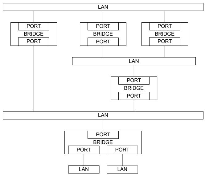
Figure 8-1—A Bridged Local Area Network
8.1.2 Filtering and relaying information
A Bridge maintains filtering and relaying information for the following purposes:
a) Duplicate frame prevention: to maintain a loop-free active topology for each VLAN;
b) Traffic segregation: to separate communication by different sets of network users;
c) Traffic reduction: to confine frames to the path(s) between their source and destination(s);
d) Traffic expediting: to classify frames in order to expedite time critical traffic;
e) Frame format conversion: to tag or untag as appropriate for the destination LAN and stations.
8.1.3 Duplicate frame prevention
A Bridge filters frames, i.e., does not relay frames received by a Bridge Port to other Ports on that Bridge, in order to prevent the duplication of frames (6.3.4). The functions that support the use and maintenance of information for this purpose are
a) Configuration and calculation of one or more spanning tree active topologies.
b) In MST Bridges, explicit configuration of the relationship between VIDs and spanning trees (8.9).
8.1.4 Traffic segregation
A Bridge can filter frames to confine them to LANs that belong to the VLAN to which they are assigned and, thus, define the VLAN's maximum extent (7.3). The functions that support the use and maintenance of information for this purpose are
a) Configuration of a PVID for each Port, to associate a VID with untagged and priority-tagged received frames (6.7.1), and parameters for Protocol VLAN Classification (6.8) if implemented;
b) Configuration of Static VLAN Registration Entries (8.8.2);
c) Configuration of the Enable Ingress Filtering parameter to enable or disable application of Static VLAN Registration Entries to received frames.
A Bridge can filter frames to partially partition a Virtual Bridged Local Area Network. Frames assigned to any given VLAN and addressed to specific end stations or groups of end stations can be excluded from relay to certain Bridge Ports. The functions that support the use and maintenance of information for this purpose are
d) Permanent configuration of Reserved Addresses (Table 8-1);
e) Configuration of Static Filtering Entries (8.8.1) and Group Registration Entries (8.8.4).
NOTE—The use of VLANs is generally less error prone and is preferred to filtering using destination addresses if a Bridged Local Area Network is to be partitioned for reasons of scale, efficiency, management, or security. Destination address filtering is the only mechanism available to Bridges that are not VLAN-aware.
8.1.5 Traffic reduction
A Bridge can filter frames to confine them to LANs that either have end stations attached to their assigned VLAN or that connect those LANs and, thus, define the current practical extent of the VLAN (7.4). LANs not attaching to or forming part of the path between the source and the destination(s) of any given communication do not have to support the transmission of related frames, potentially improving the quality of the MAC service for other communications. The functions that support the use and maintenance of information for this purpose are
a) Automatic learning of dynamic filtering information for unicast destination addresses through observation of source addresses of frames;
b) Ageing out or flushing of dynamic filtering information that has been learned to support the movement of end stations and changes in active topology;
c) Automatic inclusion and removal of Bridge Ports in the VLAN, through configuration of Dynamic VLAN Registration Entries by means of GVRP (8.8.5 and 11.2);
d) Explicit configuration of management controls associated with the operation of GVRP by means of Static VLAN Registration Entries (8.8.2 and 11.2);
e) Automatic configuration of Group Registration Entries by means of GMRP exchanges;
f) Explicit configuration of the management controls associated with the operation of GMRP by means of Group Registration Entries.
8.1.6 Traffic expediting
A Bridge classifies frames into traffic classes in order to expedite transmission of frames generated by critical or time-sensitive services. The function that supports the use and maintenance of information for this purpose is
a) Explicit configuration of traffic class information associated with the Ports of the Bridge.
8.1.7 Conversion of frame formats
A Bridge adds and removes tag headers (9.3) from frames and performs the associated frame translations that may be required. The function that supports the use and maintenance of information for this purpose is
a) Explicit configuration of tagging requirements on transmission for each Port (8.8.2, 6.7.2).
NOTE—As all incoming frames, including priority-tagged frames, are classified as belonging to a VLAN, the transmitting Port transmits VLAN-tagged frames or untagged frames. Hence, a station sending a priority-tagged frame via a Bridge will receive a response that is either VLAN-tagged or untagged, as described in 8.5.
8.2 Bridge architecture
A Bridge comprises
a) A MAC Relay Entity that interconnects the Bridge's Ports;
b) At least two Ports;
c) Higher layer entities, including at least a Spanning Tree Protocol Entity.
The VLAN-aware Bridge architecture is illustrated in Figure 8-2. The MAC Relay Entity handles the media access method independent functions of relaying frames among Bridge Ports, filtering frames, and learning filtering information. It uses the Enhanced Internal Sublayer Service (EISS) (6.6, 6.7) provided by each Bridge Port.
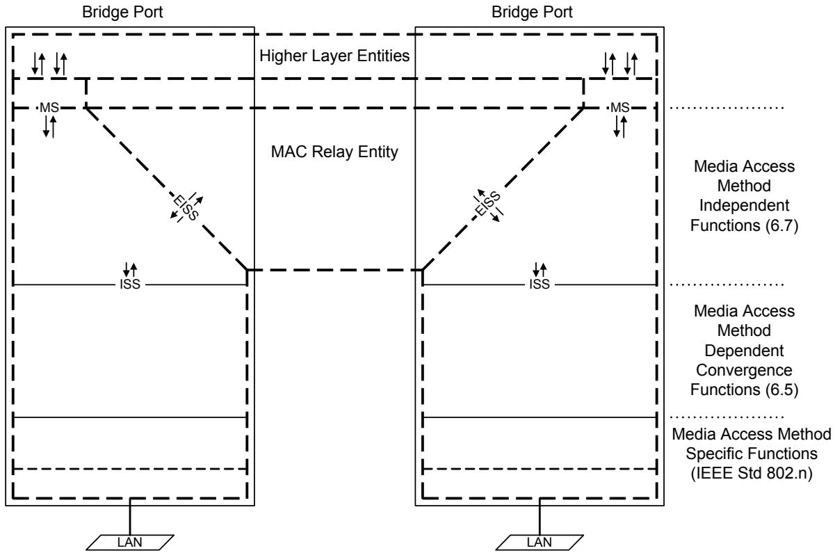
NOTE—The notation “IEEE Std 802.n” in this figure indicates that the specifications for these functions can be found in the relevant standard for the media access method concerned; for example, n would be 3 (IEEE Std 802.3) in the case of Ethernet.
Figure 8-2—VLAN-aware Bridge architecture
Each Bridge Port also functions as an end station providing one or more instances of the MAC Service. Each instance of the MAC Service is provided to a distinct LLC Entity that supports protocol identification, multiplexing, and demultiplexing, for PDU transmission and reception by one or more higher layer entities.
NOTE 1—In most cases, each Port provides a single instance of the MAC Service, to an LLC Entity that supports all Higher Layer Entities that require a point of attachment to the Port. Further instances are only provided when the specifications of the Higher Layer Entities require the use of different instances of the MAC service or of different source addresses.
An LLC Entity for each Bridge Port shall use an instance of the MAC Service provided for that Port to support the operation of LLC Type 1 procedures in order to support the operation of the Spanning Tree
Protocol Entity. Bridge Ports may support other types of LLC procedures for use by other protocols, such as protocols providing Bridge Management (8.12).
NOTE 2—For simplicity of specification, this standard refers to a single LLC Entity that can provide both the procedures specified by IEEE Std 802.2 and Ethernet Type protocol discrimination in the cases where the media access method for the attached LAN supports the latter.
If the Bridge Port can be directly attached to an IEEE 802 LAN, an instance of the MAC for that LAN type is permanently associated with the Port, handles the media access method specific functions (MAC protocol and procedures), and provides an instance of the Internal Sublayer Service (ISS) as specified in 6.4 to support frame transmission and reception by the other processes and entities that compose the Port.
Figure 8-2 illustrates a Bridge with two Ports, each directly connected to a LAN.
8.3 Model of operation
The model of operation is simply a basis for describing the functionality of the MAC Bridge. It is in no way intended to constrain real implementations of a MAC Bridge; these may adopt any internal model of operation compatible with the externally visible behavior that this standard specifies. Conformance of equipment to this standard is purely in respect of observable protocol.
The processes and entities that model the operation of a Bridge Port include
a) A Bridge Port Transmit and Receive Process (8.5) that:
1) Receives and transmit frames from and to the attached LAN (8.5, 6.4, 6.6, 6.7);
2) Can filter received frames if the VLAN tag is absent, or present, or conveys a null VID;
3) Classifies received frames into VLANs, assigning each a VID value;
4) Determines the format, VLAN-tagged or untagged, of transmitted frames;
5) Delivers and accepts frames to and from the MAC Relay Entity and LLC Entities; and
b) The LLC Entity or Entities that support Higher Layer Entities such as:
1) Spanning Tree Protocol;
2) Generic Attribute Registration Protocol;
3) Bridge Management.
The processes and entities that model the operation of the MAC Relay Entity are
c) The Forwarding Process (8.6), that:
1) Enforces a loop free active topology for frames for all VLANs (8.1.3, 8.4, 8.6.1);
2) Filters frames using their VID and destination MAC Addresses (8.1.4, 8.6.2, 8.6.3);
3) Forwards received frames that are to be relayed to other Bridge Ports;
d) The Learning Process (8.7), that observes the source addresses of frames received on each Port, and updates the Filtering Database (8.1.5, 8.4);
e) The Filtering Database (8.8), that holds filtering information and supports queries by the Forwarding Process as to whether frames with given values of VID and destination MAC Address field can be forwarded to a given Port.
Figure 8-3 illustrates a single instance of frame relay between the Ports of a Bridge with two Ports.
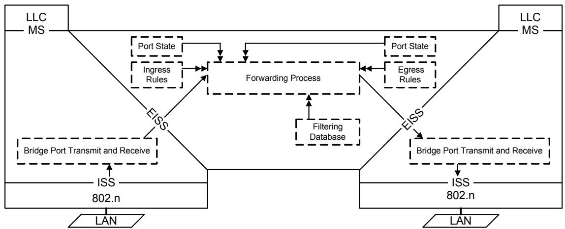
Figure 8-3—Relaying MAC frames
Figure 8-4 illustrates the inclusion of information carried by a single frame, received on one of the Ports of a Bridge with two Ports, in the Filtering Database.
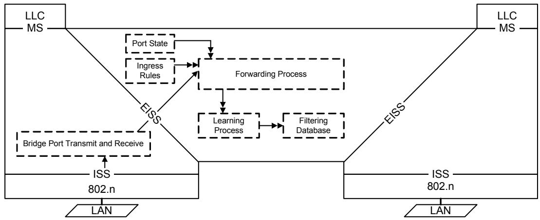
Figure 8-4—Observation of network traffic
Figure 8-5 illustrates the operation of the Spanning Tree Protocol Entity.
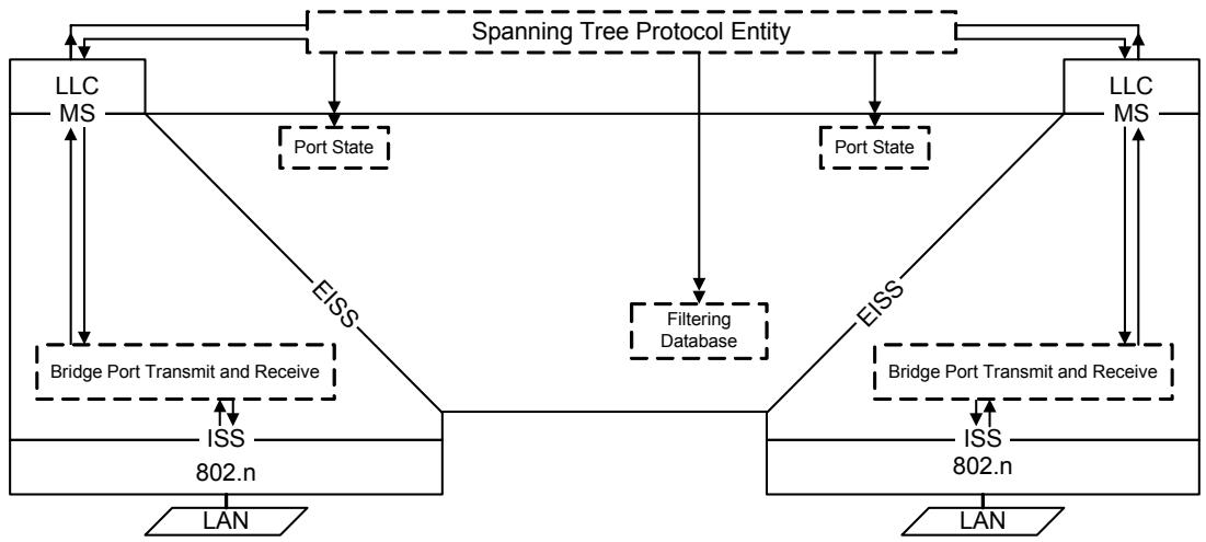
Figure 8-5—Operation of Spanning Tree protocol
Figure 8-6 illustrates the operation of the Generic Attribute Registration Protocol (GARP) Entity (8.10).
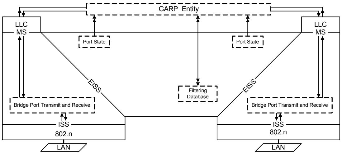
Figure 8-6—Operation of GARP
Higher Layer Entities that require only one point of attachment for the Bridge as a whole may attach to an LLC Entity that uses an instance of the MAC Service provided by a Management Port. A Management Port does not use an instance of the ISS to attach to a network but uses the Bridge Port Transmit and Receive Process and the MAC Relay Entity to provide connectivity to other Bridge Ports and the attached LANs.
NOTE—Management port functionality may also be provided by an end station connected to an IEEE 802 LAN that is wholly contained within the system that incorporates the Bridge. The absence of external connectivity to the LAN ensures that access to the management port through the bridge's relay functionality can be assured at all times.
Figure 8-7 illustrates the reception and transmission by an Entity attached to a Management Port.
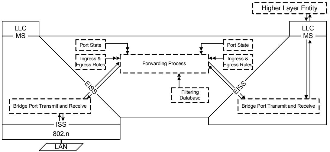
Figure 8-7—Management Port transmission and reception
8.4 Port states and the active topology
Each Bridge Port has an operational Port State that governs whether it forwards frames classified as belonging to a given VLAN and whether it learns from their source addresses.
The active topology of a Bridged Local Area Network at any time is the set of communication paths formed by interconnecting the LANs and Bridges by the forwarding Ports. The function of the distributed Spanning Tree algorithm and the Rapid Spanning Tree Protocol (RSTP, Clause 17 of IEEE Std 802.1D) used by SST Bridges to execute that algorithm, is to construct an active topology that is simply connected relative to communication between any pair of end stations, irrespective of the VLAN classification of frames used. The Multiple Spanning Tree Protocol (MSTP, Clause 13) used by MST Bridges constructs multiple active topologies, each simply and fully connected for frames belonging to any given VLAN. The forwarding and learning performed by each Bridge Port for each spanning tree is dynamically managed by RSTP or MSTP to prevent temporary loops and reduce excessive traffic in the network while minimizing denial of service following any change in the physical topology of the network.
RSTP constructs a single spanning tree, the Common Spanning Tree (CST), and maintains a single Port State for each Port. MSTP constructs multiple spanning trees, the Common and Internal Spanning Tree (CIST) and additional Multiple Spanning Tree Instances (MSTIs), and maintains a Port State for each spanning tree for each Port. An MST Bridge allocates all frames classified as belonging to a given VLAN to the CIST or to one of the MSTIs using the MST Configuration Table.
Any port that is not enabled, i.e., has MAC_Operational (6.4.2) False or has been excluded from the active topology by management setting of the Administrative Bridge Port State to Disabled, or has been dynamically excluded from forwarding and learning from MAC frames, is assigned the Port State Discarding for all spanning trees. Any Port that has learning enabled but forwarding disabled for frames allocated to a given spanning tree has the Port State Learning for that tree, and a Port that both learns and forwards frames if the Port State is Forwarding.
Figure 8-5 illustrates the operation of the Spanning Tree Protocol Entity, which operates the Spanning Tree algorithm and its related protocols, and its modification of Port state information as part of determining the active topology of the network.
Figure 8-3 illustrates the Forwarding Process's use of the Port State: first, for a Port receiving a frame, to determine whether the received frame is to be relayed through any other Ports; and second, for another Port in order to determine whether the relayed frame is to be forwarded through that particular Port.
Figure 8-4 illustrates the use of the Port state information for a Port receiving a frame, in order to determine whether the station location information is to be incorporated in the Filtering Database.
8.5 Bridge Port Transmit and Receive
The Bridge Port Transmit and Receive process supports the attachment of the Bridge Port to a network. As illustrated in Figure 8-8, it comprises two components that provide the following functions:
a) Mapping between the EISS (6.6) provided to the MAC Relay Entity, and the ISS (6.4), adding, recognizing, interpreting, and removing VLAN tags as specified in 6.7;
b) Connectivity, as specified in 8.5.1, between the following ISS access points:
1) that supporting the EISS for the MAC Relay Entity;
2) one or more that support Higher Layer Entities attached to the Port (8.5.2); and
3) that provided by the MAC Entity for the LAN attached to the Port, as specified in 6.5.
The consequence of the above connectivity is that frames relayed to a Bridge Port are both submitted to that Port's MAC Service users and transmitted on the attached LAN (see 8.13.9).
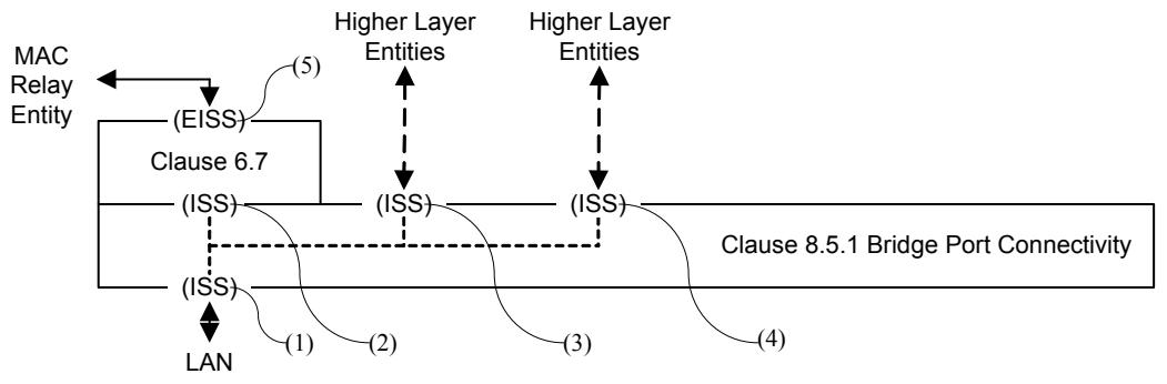
Figure 8-8—Bridge Port Transmit and Receive
A single Port for a Bridge, known as the Management Port, may support Higher Layer Entities without providing an point of attachment to a LAN (see Figure 8-7).
8.5.1 Bridge Port connectivity
Each M_UNITDATA.indication provided by the ISS access point for an attached LAN [(1) in Figure 8-8] shall result in a corresponding M_UNITDATA.indication with identical parameters at each of the access points supporting the MAC Relay and Higher Layer Entities [(2), (3) and (4)]. Each M_UNITDATA.request from the ISS access point supporting the MAC Relay Entity shall result in a corresponding M_UNITDATA.indication with identical parameters at each of the access points for the Higher Layer Entities [(3) and (4)], and a corresponding M_UNITDATA.request with identical parameters at the access point for the LAN [(1)]. Each M_UNITDATA.request from an ISS access point supporting a Higher Layer Entity shall result in a corresponding M_UNITDATA.indication with identical parameters at the access points for the MAC Relay Entity, and at other access points for Higher Layer Entities, and a corresponding M_UNITDATA.request with identical parameters at the access point for the LAN.
The MAC_Enabled, MAC_Operational, and operPointToPointMAC status parameters for the ISS access point for the MAC Relay Entity and Higher Layer Entities [(2), (3), and (4) in Figure 8-8] shall take the same value as that for the LAN (1) if that is present, and shall be True otherwise (i.e., if the Port is a Management Port).
8.5.2 Support of Higher Layer Entities
The MAC Service is provided to a Higher Layer Entity using one of ISS access points provided for that purpose by the Bridge Port Connectivity function (8.5.1).
Each ISS M_UNITDATA.indication with a destination MAC address that is either the individual address of a MAC service access point (MSAP) provided by the Bridge Port or a group address used by the attached LLC Entity shall cause an MA_UNITDATA.indication at that MSAP with destination address, source address, MSDU, and priority parameters identical to those in the M_UNITDATA.indication. No other indications or frames give rise to indications to the MAC Service user. Each MA_UNITDATA.request at the MSAP shall result in an M_UNITDATA.request at the ISS access point with identical destination address, source address, MSDU, and priority parameters.
NOTE—Appropriate selection of the PVID for a Management Port facilitates attachment of an IP stack supporting an SNMP Management Agent to any selected VLAN relayed by the Bridge.
8.6 The Forwarding Process
Each frame submitted to the MAC Relay Entity shall be forwarded subject to the constituent functions of the Forwarding Process (Figure 8-9). Each function is described in terms of the action taken for a given frame received on a given Port (termed “the reception Port”). The frame can be forwarded for transmission on some Ports (termed “transmission Ports”) and discarded without being transmitted at the other Ports.
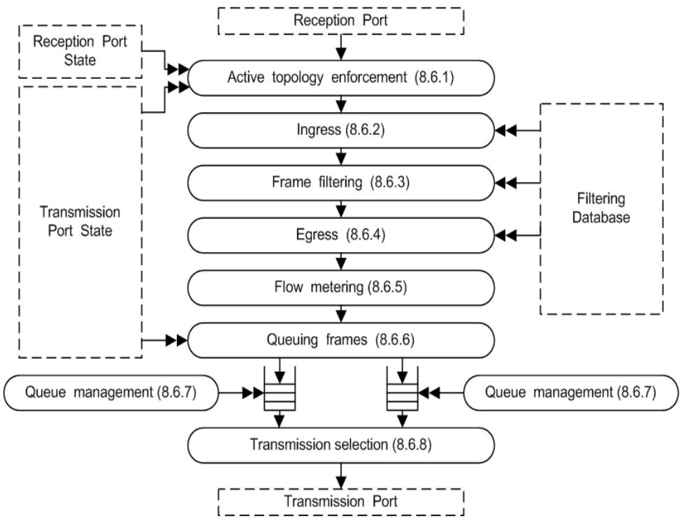
Figure 8-9—Forwarding Process functions
NOTE 1—IEEE Std 802.1Q, 2003 Edition included frame formatting and FCS recalculation functions within the Forwarding Process. This revision of the standard places those functions below the EISS interface, to allow the specification of additional methods for Bridge Port support of the EISS.
NOTE 2—The Forwarding Process models the Bridge relay function and does not take into consideration what may occur once frames are passed to the Bridge Port for transmission. Conformant implementations of some media access methods can vary the transmission order in apparent violation of the transmission selection rules when observing frames on the medium. Historic examples include the handling of access_priority in Token-Passing Bus MACs and the effect of different values for Token Holding Time in FDDI LANs. It may not be possible to test conformance to this standard for some implementations simply by relating observed LAN traffic to the functionality of the forwarding process; tests also have to allow for the (conformant) behavior of the MAC.
Figure 8-3 illustrates the operation of the Forwarding Process in a single instance of frame relay between the Ports of a Bridge with two Ports.
8.6.1 Active topology enforcement
The Forwarding Process allocates each received frame to a spanning tree. If the reception Port State for that spanning tree is Forwarding or Learning, the source address and VID are submitted to the Learning Process. If the reception Port State is Forwarding, each Bridge Port, other than the reception Port, with a Port State of Forwarding for that tree is identified as a potential transmission Port.
An SST Bridge allocates all frames to a single spanning tree, the Common Spanning Tree (CST).
An MST Bridge allocates all frames with a given VID to the CIST or to a Multiple Spanning Tree Instance (MSTI). The allocation can be controlled by configuration of the MST Configuration Table (8.9.1) maintained by the Forwarding Process, subject to constraints (if any) imposed by the allocation of VIDs to FIDs (8.8.7). VIDs allocated to different spanning trees shall also be allocated to different FIDs. VIDs allocated to a given spanning tree may share the same FID.
8.6.2 Ingress
Each Port may support an Enable Ingress Filtering parameter. A frame received on a Port that is not in the member set (8.8.9) associated with the VID shall be discarded if this parameter is set. The default value for this parameter is reset, i.e., Disable Ingress Filtering, for all Ports. Any Port that supports setting this parameter shall also support resetting it. The parameter may be configured by the management operations defined in Clause 12.
8.6.3 Frame filtering
The Forwarding Process takes filtering decisions, i.e., reduces the set of potential transmission Ports (8.6.1), for each received frame on the basis of
a) Destination MAC Address;
b) VID;
c) The information contained in the Filtering Database for that MAC Address and VID;
d) The default Group filtering behavior for the potential transmission Port (8.8.6);
in accordance with the definition of the Filtering Database entry types (8.8.1, 8.8.3, and 8.8.4). The required behavior is summarized in 8.8.6, 8.8.8, Table 8-4, Table 8-5, and Table 8-6.
Each of the Reserved MAC Addresses specified in Table 8-1 shall be permanently configured in the Filtering Database in VLAN-aware Bridges. The Filtering Database Entries for Reserved MAC Addresses shall specify filtering for all Bridge Ports and all VLANs. Management shall not provide the capability to modify or remove entries for Reserved MAC Addresses.
8.6.4 Egress
The Forwarding Process shall queue each received frame to each of the potential transmission Ports (8.6.1, 8.6.3) that is present in the member set (8.8.9) for the frame's VID.
NOTE—The Forwarding Process is modeled as receiving a frame as the parameters of a data indication and transmitting through supplying the parameters of a data request. Queueing a frame awaiting transmission amounts to placing the parameters of a data request on an outbound queue.
8.6.5 Flow classification and metering
The Forwarding Process may apply flow classification and metering to frames received on a Bridge Port.
Flow classification identifies a subset of traffic (frames) that may be subject to the same treatment in terms of metering and forwarding. Flow classification rules may be based on:
a) Destination MAC Address
b) VID
c) Priority
Table 8-1—VLAN-aware Bridge reserved addresses
<table><tr><td>Assignment</td><td>Value</td></tr><tr><td>Bridge Group Address</td><td>01-80-C2-00-00-00</td></tr><tr><td>Clause 31 (MAC Control) of IEEE Std 802.3</td><td>01-80-C2-00-00-01</td></tr><tr><td>Clause 43 (Link Aggregation) and Clause 57 (OAM) of IEEE Std 802.3</td><td>01-80-C2-00-00-02</td></tr><tr><td>IEEE Std 802.1X PAE address</td><td>01-80-C2-00-00-03</td></tr><tr><td>Reserved for future standardization—media access method specific</td><td>01-80-C2-00-00-04</td></tr><tr><td>Reserved for future standardization—media access method specific</td><td>01-80-C2-00-00-05</td></tr><tr><td>Reserved for future standardization—VLAN-aware Bridge specific</td><td>01-80-C2-00-00-06</td></tr><tr><td>Reserved for future standardization—VLAN-aware Bridge specific</td><td>01-80-C2-00-00-07</td></tr><tr><td>Reserved for future standardization—VLAN-aware Bridge specific</td><td>01-80-C2-00-00-08</td></tr><tr><td>Reserved for future standardization—VLAN-aware Bridge specific</td><td>01-80-C2-00-00-09</td></tr><tr><td>Reserved for future standardization—VLAN-aware Bridge specific</td><td>01-80-C2-00-00-0A</td></tr><tr><td>Reserved for future standardization—VLAN-aware Bridge specific</td><td>01-80-C2-00-00-0B</td></tr><tr><td>Reserved for future standardization—VLAN-aware Bridge specific</td><td>01-80-C2-00-00-0C</td></tr><tr><td>Reserved for future standardization—VLAN-aware Bridge specific</td><td>01-80-C2-00-00-0D</td></tr><tr><td>IEEE Std 802.1AB Link Layer Discovery Protocol multicast address</td><td>01-80-C2-00-00-0E</td></tr><tr><td>Reserved for future standardization—VLAN-aware Bridge specific</td><td>01-80-C2-00-00-0F</td></tr></table>
Frames classified using the same set of classification rules are subject to the same flow meter. The flow meter may discard frames on the basis of the following parameters for each received frame and previously received frames, and the timed elapsed since those frames were received:
d) The mac_service_data_unit size
The flow meter shall not base its decision on the parameters of frames received on other Bridge Ports, or on any other parameters of those Ports. The metering algorithm described in the Metro Ethernet Forum Technical Specification MEF 10 should be used.
NOTE—The flow meter described here can encompass a number of meters, each with a simpler specification. However, given the breadth of implementation choice permitted, further structuring to specify, for example, that frames can bypass a meter or are subject only to one of a number of meters provides no additional information.
8.6.6 Queuing frames
The Forwarding Process provides storage for queued frames, awaiting an opportunity to submit these for transmission. The order of frames received on the same Bridge Port shall be preserved for
a) unicast frames with a given VID, priority, and destination address and source address combination;
b) multicast frames with a given VID, priority, and destination address.
The Forwarding Process provides one or more queues for a given Bridge Port, each corresponding to a distinct traffic class. Each frame is mapped to a traffic class using the Traffic Class Table for the Port and the frame's priority. Traffic class tables may be managed. Table 8-2 shows the recommended mapping for the number of classes implemented. Up to eight traffic classes may be supported, allowing separate queues for each priority.
Table 8-2—Recommended priority to traffic class mappings
<table><tr><td rowspan="2" colspan="2"></td><td colspan="8">Number of Available Traffic Classes</td></tr><tr><td>1</td><td>2</td><td>3</td><td>4</td><td>5</td><td>6</td><td>7</td><td>8</td></tr><tr><td rowspan="8">Priority</td><td>0 (Default)</td><td>0</td><td>0</td><td>0</td><td>0</td><td>0</td><td>1</td><td>1</td><td>1</td></tr><tr><td>1</td><td>0</td><td>0</td><td>0</td><td>0</td><td>0</td><td>0</td><td>0</td><td>0</td></tr><tr><td>2</td><td>0</td><td>0</td><td>0</td><td>1</td><td>1</td><td>2</td><td>2</td><td>2</td></tr><tr><td>3</td><td>0</td><td>0</td><td>0</td><td>1</td><td>1</td><td>2</td><td>3</td><td>3</td></tr><tr><td>4</td><td>0</td><td>1</td><td>1</td><td>2</td><td>2</td><td>3</td><td>4</td><td>4</td></tr><tr><td>5</td><td>0</td><td>1</td><td>1</td><td>2</td><td>2</td><td>3</td><td>4</td><td>5</td></tr><tr><td>6</td><td>0</td><td>1</td><td>2</td><td>3</td><td>3</td><td>4</td><td>5</td><td>6</td></tr><tr><td>7</td><td>0</td><td>1</td><td>2</td><td>3</td><td>4</td><td>5</td><td>6</td><td>7</td></tr></table>
NOTE—The rationale for these mappings is discussed in Annex G (informative).
NOTE—Different numbers of traffic classes may be implemented for different Ports. Ports with media access methods that support a single transmission priority, such as CSMA/CD, can support more than one traffic class.
8.6.7 Queue management
A frame queued for transmission on a Port shall be removed from that queue
a) Following a transmit data request. No further attempt shall be made to transmit the frame on that Port even if the transmission is known to have failed.
b) If that is necessary to ensure that the maximum bridge transit delay (6.3.6) will not be exceeded at the time at which the frame would subsequently be transmitted.
c) If the associated Port leaves the Forwarding state.
The frame can be removed from the queue, and not subsequently transmitted
d) If the time for which buffering is guaranteed has been exceeded for that frame
e) By a queue management algorithm that attempts to improve the QoS provided by deterministically or probabilistically managing the queue depth based on the current and past queue depths.
Removal of a frame from a queue for any particular Port does not affect queuing of that frame for transmission on any other Port.
NOTE—Applicable queue management algorithms include RED (random early detection), and WRED (weighted random early detection) (IETF RFC 2309 [B10]).
8.6.8 Transmission selection
The following algorithm shall be supported by all Bridges as the default algorithm for selecting frames for transmission:
a) For each Port, frames are selected for transmission on the basis of the traffic classes that the Port supports. For a given supported value of traffic class, frames are selected from the corresponding queue for transmission only if all queues corresponding to numerically higher values of traffic class supported by the Port are empty at the time of selection;
b) For a given queue, the order in which frames are selected for transmission shall maintain the ordering requirement specified in 8.6.6.
Additional algorithms, selectable by management means, may be supported as an implementation option so long as the requirements of 8.6.6 are met.
8.7 The Learning Process
The Learning Process receives the source MAC Addresses and VIDs of received frames from the Forwarding Process, following the application of the ingress rules (8.6.2). It shall create or update a Dynamic Filtering Entry (8.8.3) that specifies the reception Port for the frame's source address and VID, if and only if the source address is an Individual Address, i.e., is not a Group Address, the resulting number of entries would not exceed the capacity of the Filtering Database, and the filtering utility criteria for the receiving Bridge Port are met, as specified below.
If the Filtering Database is already filled to capacity, but a new entry would otherwise be made, then an existing entry may be removed to make room for the new entry.
The purpose of filtering utility criteria is to reduce the capacity requirements of the Filtering Database and to reduce the time for which service can be denied (6.3.1) by retaining filtering information learned prior to a change in the physical topology of the network. Filtering utility criteria shall be applied to the learning and retention of information for each Filtering Identifier (FID) (8.8.7). Enhanced filtering utility criteria may be implemented for any Bridge Port as specified below (8.7.2); if implemented, both the default (8.7.1) and the enhanced criteria shall be selectable by management.
8.7.1 Default filtering utility criteria
The default for a VLAN-aware Bridge is that the member set (8.8.9) for the frame's VID includes at least one Port.
NOTE—If the member set for a given VID is empty, that VLAN is not currently active, and the Bridge will filter all frames destined for that VLAN, regardless of their destination address.
8.7.2 Enhanced filtering utility criteria
The enhanced criteria are satisfied if at least one VLAN that uses the FID includes the reception Port and at least one other Port with a Port State of Learning or Forwarding in its member set, and:
a) The operPointToPointMAC parameter is false for the reception Port; or
b) Ingress to the VLAN is permitted through a third Port.
NOTE—The third port can, but is not required to, be in the member set.
Figure 8-4 illustrates the operation of the Learning Process in the inclusion of station location information carried by a single frame, received on one of the Ports of a Bridge, in the Filtering Database.
8.8 The Filtering Database
The Filtering Database supports queries by the Forwarding Process as to whether frames received by the Forwarding Process, with given values of destination MAC Address parameter and VID, are to be forwarded through a given potential transmission Port (8.6.1, 8.6.3, 8.6.4). It contains filtering information in the form of filtering entries that are either
a) Static, and explicitly configured by management action; or
b) Dynamic, and automatically entered into the Filtering Database by the normal operation of the bridge and the protocols it supports.
Two entry types are used to represent static filtering information. The Static Filtering Entry represents static information in the Filtering Database for individual and for group MAC Addresses. It allows administrative control of
c) Forwarding of frames with particular destination addresses; and
d) The inclusion in the Filtering Database of dynamic filtering information associated with Extended Filtering Services, and use of this information.
The Filtering Database shall contain entries of the Static Filtering Entry type.
The Static VLAN Registration Entry represents all static information in the Filtering Database for VLANs. It allows administrative control of
e) Forwarding of frames with particular VIDs;
f) The inclusion/removal of tag headers in forwarded frames; and
g) The inclusion in the Filtering Database of dynamic VLAN membership information, and use of this information.
The Filtering Database may contain entries of the Static VLAN Registration Entry type.
Static filtering information is added to, modified, and removed from the Filtering Database only under explicit management control. It shall not be automatically removed by any ageing mechanism. Management of static filtering information may be carried out by use of the remote management capability provided by Bridge Management (8.12) using the operations specified in Clause 12.
Three entry types are used to represent dynamic filtering information:
h) Dynamic Filtering Entries are used to specify the Ports on which individual MAC Addresses have been learned. They are created and updated by the Learning Process (8.7), and are subject to ageing and removal by the Filtering Database.
i) Group Registration Entries support the registration of group MAC Addresses. They are created, updated, and removed by the GMRP protocol in support of Extended Filtering Services (8.8.4; 6.6.5 and Clause 10 of IEEE Std 802.1D), subject to the state of the Restricted_Group_Registration management control (10.3.2.3 of IEEE Std 802.1D). If the value of this control is TRUE, then the creation of a Group Registration Entry is not permitted unless a Static Filtering Entry exists that permits dynamic registration for the Group concerned.
j) Dynamic VLAN Registration Entries are used to specify the Ports on which VLAN membership has been dynamically registered. They are created, updated, and removed by the GVRP protocol, in support of automatic VLAN membership configuration (Clause 11), subject to the state of the Restricted_VLAN_Registration management control (11.2.3.2.3). If the value of this control is TRUE, then the creation of a Dynamic VLAN Registration Entry is not permitted unless a Static VLAN Registration Entry exists that permits dynamic registration for the VLAN concerned.
Static Filtering Entries and Group Registration Entries comprise
k) A MAC Address specification;
1) A VLAN Identifier (VID);
m) A Port Map, with a control element for each outbound Port to specify filtering for that MAC Address specification and VID.
Dynamic Filtering Entries comprise
n) A MAC Address specification;
o) A locally significant Filtering Identifier (FID; see 8.8.7);
p) A Port Map, with a control element for each outbound Port to specify filtering for that MAC Address specification in the VLAN(s) allocated to that FID.
Static and Dynamic VLAN Registration Entries comprise
q) A VLAN Identifier;
r) A Port Map, with a control element for each outbound Port to specify filtering for the VLAN.
Dynamic filtering information may be read by use of the remote management capability provided by Bridge Management (8.12) using the operations specified in Clause 12.
The Filtering Services supported by a Bridge (Basic and Extended Filtering Services) determine the default behavior of the Bridge with respect to the forwarding of frames destined for group MAC Addresses. In Bridges that support Extended Filtering Services, the default forwarding behavior for group MAC Addresses, for each Port, and for each VID, can be configured both statically and dynamically by means of Static Filtering Entries and/or Group Registration Entries that can carry the following MAC Address specifications:
s) All Group Addresses, for which no more specific Static Filtering Entry exists;
t) All Unregistered Group Addresses (i.e., all group MAC Addresses for which no Group Registration Entry exists), for which no more specific Static Filtering Entry exists.
NOTE 1—The All Group Addresses specification in item s), when used in a Static Filtering Entry with an appropriate control specification, provides the ability to configure a Bridge that supports Extended Filtering Services to behave as a Bridge that supports only Basic Filtering Services on some or all of its Ports. This might be done for the following reasons:
— The Ports concerned serve “legacy” devices that wish to receive multicast traffic, but are unable to register Group membership;
— The Ports concerned serve devices that need to receive all multicast traffic, such as routers or diagnostic devices.
The Filtering Database shall support the creation, updating, and removal of Dynamic Filtering Entries by the Learning Process (8.7). In Bridges that support Extended Filtering Services, the Filtering Database shall support the creation, updating, and removal of Group Registration Entries by GMRP (Clause 10 of IEEE Std 802.1D).
Figure 8-3 illustrates use of the Filtering Database by the Forwarding Process in a single instance of frame relay between the Ports of a Bridge with two Ports.
Figure 8-4 illustrates the creation or update of a dynamic entry in the Filtering Database by the Learning Process. The entries in the Filtering Database allow MAC Address information to be learned independently for each VLAN or set of VLANs, by relating a MAC Address to the VLAN or set of VLANs on which that address was learned. This has the effect of creating independent Filtering Databases for each VLAN or set of VLANs that is present in the network.
NOTE 2—This standard specifies a single Filtering Database that contains all Filtering Database entries; however, the inclusion of VIDs and FIDs in the filtering entries effectively provides distinct IEEE Std 802.1D-style Filtering Databases per VLAN or set of VLANs.
NOTE 3—The ability to create VLAN-dependent Filtering Database entries allows a Bridge to support
— Multiple end stations with the same individual MAC Address residing on different VLANs;
— End stations with multiple interfaces, each using the same individual MAC Address, as long as not more than one end station or interface that uses a given MAC Address resides in a given VLAN.
Figure 8-5 illustrates the operation of the Spanning Tree Protocol Entity (8.10), which operates the Spanning Tree Algorithm and Protocol, and its notification of the Filtering Database of changes in active topology signaled by that protocol.
There are no standardized constraints on the size of the Filtering Database in an implementation for which conformance to this standard is claimed. The PICS Proforma in Annex A requires the following to be specified for a given implementation:
u) The total number of entries (Static Filtering Entries, Dynamic Filtering Entries, Group Registration Entries, Static VLAN Registration Entries, and Dynamic VLAN Registration Entries) that the implementation of the Filtering Database can support, and
v) Of that total number, the total number of VLAN Registration Entries (static and dynamic) that the Filtering Database can support.
8.8.1 Static Filtering Entries
A Static Filtering Entry specifies
a) A MAC Address specification, comprising
1) An Individual MAC Address; or
2) A group MAC Address; or
3) All Group Addresses, for which no more specific Static Filtering Entry exists; or
4) All Unregistered Group Addresses, for which no more specific Static Filtering Entry exists.
b) A VLAN identifier specification, comprising:
1) The VID of a specific VLAN to which the static filtering information applies; or
2) The wildcard VID (see Table 9-2), indicating that the static filtering information applies to all VLANs for which no specific Static Filtering Entry exists.
c) A Port Map, containing a control element for each outbound Port, specifying that a frame with a destination MAC Address and VID that meets this specification is to be
1) Forwarded, independently of any dynamic filtering information held by the Filtering Database; or
2) Filtered, independently of any dynamic filtering information; or
3) Forwarded or filtered on the basis of dynamic filtering information, or on the basis of the default Group filtering behavior for the outbound Port (8.8.6) if no dynamic filtering information is present specifically for the MAC Address.
All Bridges shall have the capability to support the first two values for the MAC Address specification, both values of the VLAN identifier specification, and all three values for each control element for all Static Filtering Entries [i.e., shall have the capability to support item a1), item a2), item b1), item b2), item c1), item c2), and item c3)].
A Bridge that supports Extended Filtering Services shall have the capability to support all four values for the MAC Address specification and all three control element values for all Static Filtering Entries.
For a given MAC Address specification, a separate Static Filtering Entry with a distinct Port Map may be created for each VLAN from which frames are received by the Forwarding Process.
In addition to controlling the forwarding of frames, Static Filtering Entries for group MAC Addresses provide the Registrar Administrative Control values for the GMRP protocol (Clause 10, Clause 12, and 12.9.1 of IEEE Std 802.1D). Static configuration of forwarding of specific group addressed frames to an outbound port indicates Registration Fixed on that port: a desire to receive frames addressed to that Group even in the absence of dynamic information. Static configuration of filtering of frames that might otherwise be sent to an outbound port indicates Registration Forbidden. The absence of a Static Filtering Entry for the group address, or the configuration of forwarding or filtering on the basis of dynamic filtering information, indicates Normal Registration.
8.8.2 Static VLAN Registration Entries
A Static VLAN Registration Entry specifies
a) The VID of the VLAN to which the static filtering information applies;
b) A Port Map, consisting of a control element for each outbound Port, specifying
1) The Registrar Administrative Control values for the GVRP protocol (Clause 11) for the VLAN. In addition to providing control over the operation of GVRP, these values can also directly affect the forwarding behavior of the Bridge, as described in 8.8.9. The values that can be represented are
i) Registration Fixed; or
ii) Registration Forbidden; or
iii) Normal Registration.
2) Whether frames are to be VLAN-tagged or untagged when transmitted. The entries in the Port Map that specify untagged transmission compose the untagged set for the VLAN. The untagged set is empty if no Static VLAN Registration Entry exists for the VLAN.
A separate Static VLAN Registration Entry with a distinct Port Map may be created for each VLAN. All Bridges shall be capable of supporting all values for each control element for all Static VLAN Registration Entries; however, the ability to support more than one untagged VLAN on egress on any given Port is optional (see 5.3).
NOTE 1—In other words, it shall be possible to configure any VLAN as untagged on egress, but it is an implementation option as to whether only a single untagged VLAN per Port on egress is supported, or whether multiple untagged VLANs per Port on egress are supported.
The initial state of the Permanent Database contains a Static VLAN Registration Entry for the VLAN corresponding to the Default PVID (Table 9-2). The Port Map in this entry specifies Registration Fixed and forwarding untagged for all Ports of the Bridge. This entry may be modified or removed from the Permanent Database by means of the management operations defined in Clause 12 if the implementation supports these operations.
NOTE 2—This initial state causes the default tagging state for the PVID to be untagged, and for all other VIDs to be tagged, unless otherwise configured; however, the management configuration mechanisms allow any VID (including the PVID) to be specified as VLAN-tagged or untagged on any Port.
8.8.3 Dynamic Filtering Entries
A Dynamic Filtering Entry specifies
a) An individual MAC Address;
b) The FID, an identifier assigned by the MAC Bridge (8.8.7) to identify a set of VIDs for which no more than one Dynamic Filtering Entry can exist for any individual MAC Address;
NOTE 1—An FID identifies a set of VLANs among which Shared VLAN Learning (3.29) takes place. Any pair of FIDs identifies two sets of VLANs between which Independent VLAN Learning (3.12) takes place. The allocation of FIDs by a Bridge is described in 8.8.7.
c) A Port Map specifying forwarding for the destination MAC Address and FID to a single Port.
NOTE 2—This is equivalent to specifying a single port number; hence, this specification is directly equivalent to the specification of dynamic entries in ISO/IEC 10038: 1993.
Dynamic Filtering Entries are created and updated by the Learning Process (8.7). They shall be automatically removed after a specified time, the Ageing Time, has elapsed since the entry was created or last updated. No more than one Dynamic Filtering Entry shall be created in the Filtering Database for a given combination of MAC Address and FID.
Dynamic Filtering Entries cannot be created or updated by management.
NOTE 3—Dynamic Filtering Entries may be read by management (Clause 12). The FID is represented in the management Read operation by any one of the VIDs that it represents. For a given VID, the set of VIDs that share the same FID may also be determined by management.
The ageing out of Dynamic Filtering Entries ensures that end stations that have been moved to a different part of the network will not be permanently prevented from receiving frames. It also takes account of changes in the active topology of the network that can cause end stations to appear to move from the point of view of the bridge; i.e., the path to those end stations subsequently lies through a different Bridge Port.
The Ageing Time may be set by management (Clause 12). A range of applicable values and a recommended default is specified in Table 8-3; this is suggested to remove the need for explicit configuration in most cases. If the value of Ageing Time can be set by management, the Bridge shall have the capability to use values in the range specified, with a granularity of 1 s.
Table 8-3—Ageing time parameter value
<table><tr><td>Parameter</td><td>Recommended default value</td><td>Range</td></tr><tr><td>Ageing time</td><td>300.0 s</td><td>10.0–1 000 000.0 s</td></tr></table>
NOTE 4—The granularity is specified in order to establish a common basis for the granularity expressed in the management operations defined in Clause 12, not to constrain the granularity of the actual timer supported by a conformant implementation. If the implementation supports a granularity other than 1 s, then it is possible that the value read back by management following a Set operation will not match the actual value expressed in the Set.
The Spanning Tree Algorithm and Protocol specified in Clause 8 of IEEE Std 802.1D, 1998 Edition includes a procedure for notifying all Bridges in the network of topology change. It specifies a short value for the Ageing Timer, to be enforced for a period after any topology change (8.3.5 of IEEE Std 802.1D, 1998 Edition). While the topology is not changing, this procedure allows normal ageing to accommodate extended periods during which addressed end stations do not generate frames themselves, perhaps through being powered down, without sacrificing the ability of the network to continue to provide service after automatic configuration.
8.8.4 Group Registration Entries
A Group Registration Entry specifies
a) A MAC Address specification, comprising
1) A group MAC Address; or
2) All Group Addresses, for which no more specific Static Filtering Entry exists; or
3) All Unregistered Group Addresses, for which no more specific Static Filtering Entry exists.
b) The VID of the VLAN in which the dynamic filtering information was registered;
c) A Port Map, consisting of a control element for each outbound Port, which specifies forwarding (Registered) or filtering (Not registered) of frames destined to the MAC Address and VID.
Group Registration Entries are created, modified, and deleted by the operation of GMRP (Clause 10 of IEEE Std 802.1D, as modified by Clause 10 of this standard). No more than one Group Registration Entry shall be created in the Filtering Database for a given combination of MAC Address specification and VID.
NOTE—It is possible to have a Static Filtering Entry that has values of Forward or Filter on some or all Ports that mask the dynamic values held in a corresponding Group Registration Entry. The values in the Group Registration Entry will continue to be updated by GMRP; hence, subsequent modification of that entry to allow the use of dynamic filtering information on one or more Ports immediately activates the true GMRP registration state that was hitherto masked by the static information.
The creation of Group Registration Entries is subject to the Restricted_Group_Registration management control (10.3.2.3 of IEEE Std 802.1D). If the value of this control is TRUE, a dynamic entry for a given Group may only be created if a Static Filtering Entry already exists for that Group, in which the Registrar Administrative Control value is Normal Registration.
8.8.5 Dynamic VLAN Registration Entries
A Dynamic VLAN Registration Entry specifies
a) The VID of the VLAN to which the dynamic filtering information applies;
b) A Port Map with a control element for each outbound Port specifying whether the VLAN is registered on that Port.
A separate Dynamic VLAN Registration Entry with a distinct Port Map may be created for each VLAN from which frames are received by the Forwarding Process.
The creation of Dynamic VLAN Registration Entries is subject to the Restricted_VLAN_Registration management control (11.2.3.2.3). If the value of this control is TRUE, a dynamic entry for a given VLAN may only be created if a Static VLAN Registration Entry already exists for that VLAN, in which the Registrar Administrative Control value is Normal Registration.
8.8.6 Default Group filtering behavior
Forwarding and filtering of group-addressed frames may be managed by specifying defaults for each VLAN and outbound Port. The behavior of each of these defaults, as modified by the control elements of more explicit Filtering Database entries applicable to a given frame's MAC Address, VLAN classification, and outbound Port, is as follows:
NOTE 1—As stated in 8.8.1, for a given MAC Address, there may be separate Static Filtering Entries with a distinct Port Map for each VLAN.
a) Forward All Groups. The frame is forwarded, unless an explicit Static Filtering Entry specifies filtering independent of any dynamic filtering information.
b) Forward Unregistered Groups. The frame is forwarded, unless
1) An explicit Static Filtering Entry specifies filtering independent of any dynamic filtering information; or
2) An explicit Static Filtering Entry specifies forwarding or filtering on the basis of dynamic filtering information, and an applicable explicit Group Registration Entry exists specifying filtering; or
3) An applicable explicit Static Filtering Entry does not exist, but an applicable Group Registration entry specifies filtering.
c) Filter Unregistered Groups. The frame is filtered unless
1) An explicit Static Filtering Entry specifies forwarding independent of any dynamic filtering information; or
2) An explicit Static Filtering Entry specifies forwarding or filtering on the basis of dynamic filtering information, and an applicable explicit Group Registration Entry exists specifying forwarding; or
3) An applicable explicit Static Filtering Entry does not exist, but an applicable Group Registration entry specifies forwarding.
In Bridges that support only Basic Filtering Services, the default Group filtering behavior is Forward All Groups for all Ports of the Bridge, for all VLANs.
NOTE 2—Forward All Groups corresponds directly to the behavior specified in ISO/IEC 10038:1993 when forwarding group MAC Addressed frames for which no static filtering information exists in the Filtering Database. Forward All Groups makes use of information contained in Static Filtering Entries for specific group MAC Addresses, but overrides any information contained in Group Registration Entries. Forward Unregistered Groups is analogous to the forwarding behavior of a Bridge with respect to individual MAC Addresses. If there is no static or dynamic information for a specific group MAC Address, then the frame is forwarded; otherwise, the frame is forwarded in accordance with the statically configured or dynamically learned information.
In Bridges that support Extended Filtering Services, the default Group filtering behavior for each outbound Port for each VLAN is determined by the following information contained in the Filtering Database:
d) Any Static Filtering Entries applicable to that VLAN with a MAC Address specification of All Group Addresses or All Unregistered Group Addresses;
e) Any Group Registration Entries applicable to that VLAN with a MAC Address specification of All Group Addresses or All Unregistered Group Addresses.
The means whereby this information determines the default Group filtering behavior is specified in 8.8.8, Table 8-5, and Table 8-6.
NOTE 3—The result is that the default Group filtering behavior for each VLAN can be configured for each Port of the Bridge via Static Filtering Entries, determined dynamically via Group Registration Entries created/updated by GMRP (Clause 10), or both. For example, in the absence of any static or dynamic information in the Filtering Database for All Group Addresses or All Unregistered Group Addresses, the default Group filtering behavior will be Filter Unregistered Groups on all Ports, for all VLANs. Subsequently, the creation of a Dynamic Group Registration Entry for All
Unregistered Group Addresses indicating “Registered” for a given VLAN on a given Port would cause that Port to exhibit Forward Unregistered Groups behavior for that VLAN. Similarly, creating a Static Filtering Entry for All Group Addresses indicating “Registration Fixed” on a given Port for that VLAN would cause that Port to exhibit Forward All Groups behavior.
Hence, by using appropriate combinations of “Registration Fixed,” “Registration Forbidden,” and “Normal Registration” in the Port Maps of Static Filtering Entries for the All Group Addresses and All Unregistered Group Addresses address specifications, it is possible, for a given Port and VLAN, to
— Fix the default Group filtering behavior to be just one of the three behaviors described above; or
— Restrict the choice of behaviors to a subset of the three, and allow GMRP registrations (or their absence) to determine the final choice; or
— Allow any one of the three behaviors to be adopted, in accordance with any registrations received via GMRP.
8.8.7 Allocation of VIDs to FIDs
The allocation of VIDs to FIDs within a Bridge determines how learned individual MAC Address information is used in forwarding/filtering decisions within a Bridge; whether such learned information is confined to individual VLANs, shared among all VLANs, or confined to specific sets of VLANs.
The allocation of VIDs to FIDs is determined on the basis of
a) The set of VLAN Learning Constraints that have been configured into the Bridge (by means of the management operations defined in Clause 12);
b) Any fixed mappings of VIDs to FIDs that may have been configured into the Bridge (by means of the management operations defined in Clause 12);
c) The set of active VLANs (i.e., those VLANs on whose behalf the Bridge may be called on to forward frames). A VLAN is active if either of the following is true:
1) The VLAN's member set (8.8.9) contains one Port that is in a forwarding state, and at least one other Port of the Bridge is both in a forwarding state and has Ingress Filtering (8.6.2) disabled;
2) The VLAN's member set contains two or more Ports that are in a forwarding state.
d) The capabilities of the Bridge with respect to the number of FIDs that it can support, and the number of VIDs that can be allocated to each FID.
A Bridge shall support a minimum of one FID and may support up to 4094 FIDs. For the purposes of the management operations, FIDs are numbered from 1 through N, where N is the maximum number of FIDs supported by the implementation.
A Bridge shall support the ability to allocate at least one VID to each FID and may support the ability to allocate more than one VID to each FID.
The number of VLAN Learning Constraints supported by a Bridge is an implementation option.
NOTE—In an SVL/IVL Bridge (3.31), a number of FIDs are supported, and one or more VID can be mapped to each FID. In an SVL Bridge (3.30), a single FID is supported, and all VIDs are mapped to that FID. In an IVL Bridge (3.13), a number of FIDs are supported, and only one VID can be mapped to each FID.
An MST Bridge shall support the ability to allocate at least one FID to each spanning tree and may support the ability to allocate more than one FID to each spanning tree.
NOTE—In other words, the number of FIDs supported by the Bridge must be greater than or equal to the number of spanning trees supported by the Bridge.
An MST Bridge shall ensure that the maximum supported numbers of FIDs and VLANs can be associated unambiguously. This requires either 1) a number of fixed VID to FID allocations at least equal to the maximum number of VLANs supported; or 2) one I Constraint entry per FID supported and one S Constraint entry per MSTI supported, or both (8.8.7.1).
8.8.7.1 Fixed and dynamic VID to FID allocations
A Bridge may support the ability to define fixed allocations of specific VIDs to specific FIDs, via an allocation table that may be read and modified by means of the management operations defined in Clause 12. For each VID supported by the implementation, the allocation table indicates one of the following:
a) The VID is currently not allocated to any FID; or
b) A fixed allocation has been defined (via management), allocating this VID to a specific FID; or
c) A dynamic allocation has been defined (as a result of applying the VLAN Learning Constraints), allocating this VID to a specific FID.
For any VID that has no fixed allocation defined, the Bridge can dynamically allocate that VID to an appropriate FID, in accordance with the current set of VLAN Learning Constraints.
8.8.7.2 VLAN Learning Constraints
There are two types of VLAN Learning Constraint:
a) A Shared Learning Constraint (or S Constraint) asserts that Shared VLAN Learning shall occur between a pair of identified VLANs. S Constraints are of the form {A S B}, where A and B are VIDs. An S constraint is interpreted as meaning that Shared VLAN Learning shall occur between the VLANs identified by the pair of VIDs;
b) An Independent Learning Constraint (or I Constraint) asserts that a given VLAN is a member of a set of VLANs among which Independent VLAN Learning shall occur. I Constraints are of the form {A I N}, where A is a VID and N is an Independent Set Identifier. An I Constraint is interpreted as meaning that Independent VLAN Learning shall occur among the set of VLANs comprising VLAN A and all other VLANs identified in I Constraints that carry the same Independent Set Identifier, N.
A given VID may appear in any number (including zero) of S Constraints and/or I Constraints.
NOTE 1—S Constraints are
— Symmetric: e.g., {A S B} and {B S A} both express an identical constraint;
— Transitive: e.g., {A S B}, {B S C} implies the existence of a third constraint, {A S C};
— Reflexive: e.g., {A S A} is a valid S Constraint.
I Constraints are not
— Symmetric: e.g., {A I 1} and {1 I A} express different constraints;
— Transitive: e.g., ( $\{AI1\}$ , $\{BI1\}$ , $\{BI2\}$ , $\{CI2\}$ ) does not imply either $\{AI2\}$ or $\{CI1\}$ .
The allocation of VIDs to FIDs shall be such that, for all members of the set of active VLANs (8.8.7),
c) A given VID shall be allocated to exactly one FID;
d) If a given VID appears in an I Constraint, then it shall not be allocated to the same FID as any other VID that appears in an I Constraint with the same Independent Set Identifier;
e) If a given VID appears in an S Constraint (either explicit, or implied by the transitive nature of the specification), then it shall be allocated to the same FID as the other VID identified in the same S Constraint;
f) If a VID does not appear in any S or I Constraints, then the Bridge may allocate that VID to any FID of its choice.
NOTE 2—The intent is that the set of Learning Constraints is defined on a global basis; i.e., that all VLAN-aware Bridges are configured with the same set of constraints (although individual constraints may well be defined and distributed by different managers/administrators). Any Bridge, therefore, sees the complete picture in terms of the Learning Constraints that apply to all VLANs present in the network, regardless of whether they all apply to VLANs that are present in that particular Bridge. This standard provides the definition, in Clause 12, of managed objects and operations that model how individual constraints can be configured in a Bridge; however, the issue of how a distributed management system might ensure the consistent setting of constraints in all Bridges in a network is not addressed by this standard.
8.8.7.3 VLAN Learning Constraint inconsistencies and violations
The application of the rules specified in 8.8.7.2, coupled with any fixed allocations of VIDs to FIDs that may have been configured, can result in the Bridge detecting Learning Constraint inconsistencies and/or violations (i.e., can result in situations where there are inherent contradictions in the combined specification of the VLAN Learning Constraints and the fixed allocations, or the Bridge's own limitations mean that it cannot meet the set of VLAN Learning Constraints that have been imposed on it).
A Bridge detects a Learning Constraint inconsistency if
a) The VLAN Learning Constraints, coupled with any fixed VID to FID allocations, are such that, if any given pair of VLANs became members of the set of active VLANs (8.8.7), the result would be a simultaneous requirement for Independent VLAN Learning and for Shared VLAN Learning for those two VLANs. Such an inconsistency would require the Bridge to allocate that pair of VIDs both to the same FID and to different FIDs.
Learning Constraint inconsistencies are detected when a management operation (12.10.3) attempts to set a new Learning Constraint value, or to modify the fixed VID to FID allocations. If the new constraint or allocation that is the subject of the operation is inconsistent with those already configured in the Bridge, then the management operation shall not be performed and an error response shall be returned.
A Bridge detects a Learning Constraint violation if
b) The Bridge does not support the ability to map more than one VID to any given FID, and the VLAN Learning Constraints indicate that two or more members of the active set of VLANs require to be mapped to the same FID; or
c) The number of FIDs required in order to correctly configure the Bridge to meet the VLAN Learning Constraints and fixed VID to FID allocations for all members of the active set of VLANs exceeds the number of FIDs supported by the Bridge.
Learning Constraint violations are detected
d) When a VLAN that was hitherto not a member of the set of active VLANs (8.8.7) becomes active, either as a result of management action or as a result of the operation of GVRP, resulting in the Bridge no longer being able to support the defined set of constraints and/or fixed allocations for the set of active VLANs; or
e) When other management reconfiguration actions, such as defining a new Learning Constraint or fixed VID to FID allocation, results in the Bridge no longer being able to support the defined set of constraints and/or fixed allocations for the set of active VLANs.
On detection of a violation, the Bridge issues the Notify Learning Constraint Violation management notification (12.10.3.10) in order to alert any management stations to the existence of the violation. There is the potential for a single change in configuration to result in more than one VLAN whose constraints cannot be met; in such cases, multiple notifications are generated.
8.8.8 Querying the Filtering Database
If a frame is classified into a VLAN containing a given outbound Port in its member set (8.8.9), forwarding or filtering through that Port is determined by the control elements of filtering entries for the frame's destination MAC Address and for VLANs with the same VID or Filtering Identifier (FID, 8.8.7) as the frame's VLAN.
Each entry in the Filtering Database for a MAC Address comprises
a) A MAC Address specification;
b) A VID or, in the case of Dynamic Filtering Entries, an FID;
c) A Port Map, with a control element for each outbound Port.
For Dynamic Filtering Entries, the FID that corresponds to a given VID is determined as specified in 8.8.7.
For a given VID, a given individual MAC Address specification can be included in the Filtering Database in a Static Filtering Entry, a Dynamic Filtering Entry, both, or neither. Table 8-4 combines Static Filtering Entry and Dynamic Filtering Entry information for an individual MAC Address to specify forwarding, or filtering, of a frame with that destination MAC Address and VID through an outbound Port.
NOTE 1—The use of FID in this table for Static Filtering Entries, and the text in parentheses in the headings, reflects the fact that, where more than one VID maps to a given FID, there may be more than one Static Filtering Entry that affects the forwarding decision for a given individual MAC Address. The effect of all Static Filtering Entries for that address, and for VIDs that correspond to that FID, is combined, such that, for a given outbound Port:
— IF <any static entry for any VIDs that map to that FID specifies Forwarding> THEN <result = Forwarding>
— ELSE IF <any static entry for any VIDs that map to that FID specifies Filtering> THEN <result = Filtering>
— ELSE <result = Use Dynamic Filtering Information>
Table 8-4—Combining Static and Dynamic Filtering Entries for an individual MAC Address
<table><tr><td rowspan="3">Filtering Information</td><td colspan="5">Control Elements in any Static Filtering Entry or Entries for this individual MAC Address, FID, and outbound Port specify:</td></tr><tr><td rowspan="2">Forward (Any Static Filtering Entry for this Address/ FID/Port specifies Forward)</td><td rowspan="2">Filter (No Static Filtering Entry for this Address/ FID/Port specifies Forward)</td><td colspan="3">Use Dynamic Filtering Information (No Static Filtering Entry for this Address/FID/Port specifies Forward or Filter), or no Static Filtering Entry present. Dynamic Filtering Entry Control Element for this individual MAC Address, FID and outbound Port specifies:</td></tr><tr><td>Forward</td><td>Filter</td><td>No Dynamic Filtering Entry present</td></tr><tr><td>Result</td><td>Forward</td><td>Filter</td><td>Forward</td><td>Filter</td><td>Forward</td></tr></table>
Table 8-5 specifies the result, Registered or Not Registered, of combining a Static Filtering Entry and a Group Registration Entry for the “All Group Addresses” address specification, and for the “All Unregistered Group Addresses” address specification for an outbound Port.
Table 8-5—Combining Static Filtering Entry and Group Registration Entry for “All Group Addresses” and “All Unregistered Group Addresses”
<table><tr><td rowspan="3">Filtering Information</td><td colspan="5">Static Filtering Entry Control Element for this group MAC Address, VID, and outbound Port specifies:</td></tr><tr><td rowspan="2">Registration Fixed (Forward)</td><td rowspan="2">Registration Forbidden (Filter)</td><td colspan="3">Use Group Registration Information, or no Static Filtering Entry present. Group Registration Entry Control Element for this group MAC Address, VID and outbound Port specifies:</td></tr><tr><td>Registered (Forward)</td><td>Not Registered (Filter)</td><td>No Group Registration Entry present</td></tr><tr><td>Result</td><td>Registered</td><td>Not Registered</td><td>Registered</td><td>Not Registered</td><td>Not Registered</td></tr></table>
Table 8-6 combines Static Filtering Entry and Group Registration Entry information for a specific group MAC Address with the Table 8-5 results for All Group Addresses and All Unregistered Group Addresses to specify forwarding, or filtering, of a frame with that destination group MAC Address through an outbound Port.
Where a given VID is allocated to the same FID as one or more other VIDs, it is an implementation option as to whether
d) The results shown in Table 8-6 directly determine the forwarding/filtering decision for a given VID and group MAC Address (i.e., the operation of the Bridge with respect to group MAC Addresses ignores the allocation of VIDs to FIDs); or
e) The results for a given MAC Address and VID are combined with the corresponding results for that MAC Address for each other VID that is allocated to the same FID, so that if the Table 8-6 result is Forward in any one VLAN that shares that FID, then frames for that group MAC Address will be forwarded for all VLANs that share that FID (i.e., the operation of the Bridge with respect to group MAC Addresses takes account of the allocation of VIDs to FIDs).
NOTE 2—In case d), the implementation effectively operates a single FDB per VLAN for group MAC Addresses. In case e), the implementation combines static and registered information for group MAC Addresses in accordance with the VID to FID allocations currently in force, in much the same manner as for individual MAC Addresses.
8.8.9 Determination of the member set for a VLAN
The VLAN configuration information contained in the Filtering Database for a given VLAN may include a Static VLAN Registration Entry (8.8.2) and/or a Dynamic VLAN Registration Entry (8.8.5). This information defines the member set, the Ports through which members of that VLAN can be reached.
For a given VID, the Filtering Database can contain a Static VLAN Registration Entry, a Dynamic VLAN Registration Entry, both, or neither. Table 8-7 combines Static VLAN Registration Entry and Dynamic VLAN Registration Entry information for a VLAN and Port to give a result member, or not member, for the Port. The member set for a given VLAN consists of all Ports for which the result is member.
Table 8-6—Forwarding or Filtering for specific group MAC Addresses
<table><tr><td rowspan="3" colspan="4"></td><td colspan="5">Static Filtering Entry Control Element for this group MAC Address, VID and outbound Port specifies:</td></tr><tr><td rowspan="2">Registration Fixed (Forward)</td><td rowspan="2">Registration Forbidden (Filter)</td><td colspan="3">Use Group Registration Information, or no Static Filtering Entry present. Group Registration Entry Control Element for this group MAC Address, VID and outbound Port specifies:</td></tr><tr><td>Registered (Forward)</td><td>Not Registered (Filter)</td><td>No Group Registration Entry present</td></tr><tr><td rowspan="3">All Group Addresses control elements for this VID and Port specify (Table 8-5):</td><td rowspan="2">Not Registered</td><td rowspan="2">All Unregistered Group Addresses control elements for this VID and Port specify (Table 8-5):</td><td>Not Registered</td><td>Forward</td><td>Filter</td><td>Forward</td><td>Filter</td><td>Filter (Filter Unregistered Groups)</td></tr><tr><td>Registered</td><td>Forward</td><td>Filter</td><td>Forward</td><td>Filter</td><td>Forward (Forward Unregistered Groups)</td></tr><tr><td colspan="3">Registered</td><td>Forward</td><td>Filter</td><td>Forward (Forward All Groups)</td><td>Forward (Forward All Groups)</td><td>Forward (Forward All Groups)</td></tr></table>
Table 8-7—Determination of whether a Port is in a VLAN's member set
<table><tr><td rowspan="3">Filtering Information</td><td colspan="5">Static VLAN Registration Entry Control Element for this VID and Port specifies:</td></tr><tr><td rowspan="2">Registration Fixed</td><td rowspan="2">Registration Forbidden</td><td colspan="3">Normal Registration, or no Static VLAN Registration Entry present. Dynamic VLAN Registration Entry Control Element for this VID and Port specifies:</td></tr><tr><td>Registered</td><td>Not Registered</td><td>No Dynamic VLAN Registration Entry present</td></tr><tr><td>Result</td><td>Member</td><td>Not member</td><td>Member</td><td>Not member</td><td>Not member</td></tr></table>
The Forwarding Process uses the member set to apply ingress (8.6.2) and egress rules (8.6.4) for the VLAN.
8.8.10 Permanent Database
The Permanent Database provides fixed storage for a number of Static Filtering Entries and Static VLAN Registration Entries. The Filtering Database shall be initialized with the Filtering Database Entries contained in this fixed data store.
Entries may be added to and removed from the Permanent Database under explicit management control, using the management functionality defined in Clause 12. Changes to the contents of Static Filtering Entries or Static VLAN Registration Entries in the Permanent Database do not affect forwarding and filtering decisions taken by the Forwarding Process or the egress rules until such a time as the Filtering Database is re-initialized.
NOTE 1—This aspect of the Permanent Database can be viewed as providing a “boot image” for the Filtering Database, defining the contents of all initial entries, before any dynamic filtering information is added.
NOTE 2—Subclause 10.3.2.3 of IEEE Std 802.1D defines an initial state for the contents of the Permanent Database, required for the purposes of GMRP operation.
8.9 MST configuration information
In order to support multiple spanning trees, an MST Bridge has to be configured with an unambiguous assignment of VIDs to spanning trees. This is achieved by:
a) Ensuring that the allocation of VIDs to FIDs (8.8.7) is unambiguous; and
b) Ensuring that each FID supported by the Bridge is allocated to exactly one Spanning Tree.
The first of these requirements is met by configuring a set of VLAN learning constraints and/or fixed VID to FID mappings that are self-consistent, and which define an I Constraint, an S Constraint, or a fixed VID to FID allocation for all VIDs supported by the Bridge.
The second requirement is met by means of the FID to MSTI Allocation Table (8.9.3).
The combination of the VID to FID allocations and the FID to MSTI allocations defines a mapping of VIDs to spanning trees, represented by the MST Configuration Table (8.9.1).
8.9.1 MST Configuration Table
The MST Configuration Table defines, for each VID, the MSTID of the spanning tree instance to which the VID is allocated.
The MST Configuration Table cannot be configured directly; configuration of the table occurs as a consequence of configuring the relationships between VIDs and FIDs (8.8.7) and between FIDs and spanning trees (8.9.3).
8.9.2 MST configuration identification
For two or more MST Bridges to be members of the same MST Region (3.18), it is necessary for those Bridges to be directly connected together (i.e., interconnected only by means of LANs, without intervening Bridges that are not members of the region), and for them to support the same MST Region configuration. Two MST Region configurations are considered to be the same if the correspondence between VIDs and spanning trees is identical in both configurations.
NOTE 1—If two adjacent MST Bridges consider themselves to be in the same MST Region despite having different mappings of VIDs to spanning trees, then the possibility exists of undetectable loops arising within the MST Region.
In order to ensure that adjacent MST Bridges are able to determine whether they are part of the same MST Region, the MST BPDU supports the communication of an MST Configuration Identifier (13.7).
NOTE 2—As the MST Configuration Identifier is smaller than the mapping information that it summarizes, there is a small but finite possibility that two MST Bridges will assume that they have the same MST Region Configuration when this is not actually the case. However, given the size of the identifier, this standard assumes that this possibility is sufficiently small that it can safely be ignored. Appropriate use of the Configuration Name and Revision Level portions of the identifier can remove the possibility of an accidental match between MST Configuration Identifiers that are derived from different configurations within a single administrative domain (see 13.7).
8.9.3 FID to MSTI Allocation Table
The FID to MSTI Allocation Table defines, for all FIDs that the Bridge supports, the MSTID of the spanning tree instance to which the FID is allocated. An MSTID of zero is used to identify the CIST.
NOTE—The management operations defined in 12.12 make use of the concept of an MSTI List to instantiate/de-instantiate MST instances and will only permit the allocation of FIDs to MSTIDs that are present in the MSTI List.
8.10 Spanning Tree Protocol Entity
Figure 8-5 illustrates the operation of the Spanning Tree Protocol Entity, including the reception and transmission of frames containing BPDUs, the modification of the state information associated with individual Bridge Ports, and the notification of the Filtering Database of changes in active topology.
A given MST bridge is not required to support all of the spanning trees that exist within the MST bridged network. That is, the number of spanning trees operated by the Spanning Tree Protocol Entity in a given bridge may be different from the number operated by that in another bridge. However, as a direct consequence of the conditions stated in 8.9.2, the number of instances of the Spanning Tree Protocol operated by a given MST Bridge is the same for all Bridges that are members of a given MST Region.
8.11 GARP Entities
The GARP Protocol Entities operate the Algorithms and Protocols associated with the GARP Applications supported by the Bridge and consist of the set of GARP Participants for those GARP Applications (Clause 10 and 12.3 of IEEE Std 802.1D).
Figure 8-6 illustrates the operation of a GARP Protocol Entity, including the reception and transmission of frames containing GARP PDUs, the use of control information contained in the Filtering Database, and the notification of the Filtering Database of changes in filtering information.
8.12 Bridge Management Entity
In order to facilitate interoperable management of Bridges by remote means (as opposed to management via some kind of management console attached directly to the Bridge), it is recommended that SNMP should be the protocol that is used, in conjunction with the SMIv2 MIB modules specified in the following documents:
a) IETF RFC 1493 $^{15}$ ;
b) IETF RFC 2674 $^{16}$ ;
c) RSTP MIB $^{17}$ ;
d) MSTP MIB. $^{18}$
NOTE—This standard is not fully complete, in terms of its specification of management capability using SNMP. Management of network components supporting MSTP is possible, but in the absence of a standardized MIB to ensure interoperability, such management operations may be complex. It is anticipated that a new project will be initiated in order to standardize an SMIv2 MIB definition as an amendment to this standard.
8.13 Addressing
All MAC Entities communicating across a Bridged Local Area Network use 48-bit addresses. These can be Universally Administered Addresses or a combination of Universally Administered and Locally Administered Addresses.
8.13.1 End stations
Frames transmitted between end stations using the MAC Service carry the MAC Address of the source and destination peer end stations in the source and destination address fields of the frames, respectively. The address, or other means of identification, of a Bridge is not carried in frames transmitted between peer users for the purpose of frame relay in the network.
In the absence of explicit filters configured via management as Static Filtering Entries, or via GMRP as Group Registration Entries (8.8, Clause 10), frames with a destination address of the broadcast address or any other group address that is not a Reserved Address (8.6.3) are assigned to a VLAN and relayed throughout that VLAN.
8.13.2 Bridge Ports
A separate individual MAC Address is associated with each instance of the MAC Service provided to an LLC Entity. That MAC Address is used as the source address of frames transmitted by the LLC Entity.
Media access method specific procedures can require the transmission and reception of frames that use an individual MAC Address associated with the Bridge Port, but neither originate from nor are delivered to a MAC Service user. Where an individual MAC Address is associated with the provision of an instance of the MAC Service by the Port, that address can be used as the source and/or the destination address of such frames, unless the specification of the media access method specific procedures requires otherwise.
8.13.3 Use of LLC by Spanning Tree Protocol and GARP Entities
Both Spanning Tree Protocol and GARP Entities uses the DL_UNITDATA.request and DL_UNITDATA.indication primitives (ISO/IEC 8802-2) provided by individual LLC Entities associated with each Bridge Port to transmit and receive. The source_address and destination_address parameters of the DL_UNITDATA.request shall both denote the standard LLC address assigned to the Bridge Spanning Tree Protocol (Table 8-8). Each DL_UNITDATA request primitive gives rise to the transmission of an LLC UI command PDU, which conveys the BPDU or GARP PDU in its information field. $^{19}$
IEEE Std 802.1D defines a Protocol Identifier field, present in all BPDUs (Clause 9 of IEEE Std 802.1D) and GARP PDUs (12.11 of IEEE Std 802.1D), which serves to identify different protocols supported within the scope of the LLC address assignment. Further values of this field are reserved for future standardization. A Spanning Tree Protocol Entity or GARP Protocol Entity that receives a BPDU or a GARP PDU with an unknown Protocol Identifier shall discard that PDU.
Table 8-8—Standard LLC address assignment
<table><tr><td>Assignment</td><td>Value</td></tr><tr><td>Bridge spanning tree protocol</td><td>01000010</td></tr></table>
Code Representation: The least significant bit of the value shown is the right-most. The bits increase in significance from right to left. It should be noted that the code representation used here has been chosen in order to maintain consistency with the representation used elsewhere in this standard, and with the representation used in IEEE Std 802.1D.
8.13.4 Reserved MAC Addresses
Any frame with a destination address that is a Reserved MAC Address shall not be forwarded by a Bridge. Reserved MAC Addresses for VLAN-aware Bridges are specified in Table 8-1. These group MAC Addresses are reserved for assignment to standard protocols, according to the criteria for such assignments (Clause 5.5 of ISO/IEC TR 11802-2).
8.13.5 Group MAC Addresses for spanning tree protocols
A Spanning Tree Protocol Entity uses an instance of the MAC Service provided by each of the Bridge's Ports to transmit frames addressed to the Spanning Tree Protocol Entities of all the other Bridges attached to the same LAN as that Port. A 48-bit universally administered Group Address, known as the Bridge Group Address, has been assigned (Table 8-1) for use by VLAN-aware Bridges for this purpose.
It is essential to the operation of the spanning tree protocols that frames with this destination address both reach all peer protocol entities attached to the same LAN and do not reach protocol entities attached to other LANs. The Bridge Group Address is therefore included in the block of VLAN-aware Bridge Reserved MAC Addresses and is always filtered by Bridges (8.6.3).
The source MAC address field of frames transmitted by Spanning Tree Protocol Entities contains the individual MAC Address for the Bridge Port used to transmit the frame.
8.13.6 Group MAC Addresses for GARP Applications
A GARP Entity that supports a given GARP Application transmits frames addressed to all other GARP Entities that implement the same GARP Application. The peers of each such entity bound a region of the network that contains no peers, commonly a single LAN in the case where all Bridges attached to the LAN implement the application. A distinct universally administered 48-bit Group Address is assigned to each GARP application. Filtering Database Entries for each GARP Application address assigned to an application that is supported by a VLAN-aware Bridge should be configured in the Filtering Database so as to confine frames for that application to the peer region, while addresses for applications that are not supported should not be included.
A set of 48-bit Universal Addresses, known as GARP Application addresses, have been assigned for use by VLAN-aware Bridges. The values of the GARP Application addresses are defined in Table 12-1 of IEEE Std 802.1D. These group MAC Addresses are reserved for assignment to standard protocols, according to the criteria for such assignments (Clause 5.5 of ISO/IEC TR 11802-2).
NOTE—Table 11-1 allocates a group MAC Address for use by the GVRP application; however, the value allocated in that table is one of the GARP Application addresses reserved by Table 12-1 of IEEE Std 802.1D.
The source address field of MAC frames conveying BPDUs or GARP PDUs contains the individual MAC Address for the Bridge Port through which the PDU is transmitted (8.13.2).
8.13.7 Bridge Management Entities
The recommended protocol for remote Bridge management is SNMP, which typically uses IP as a network layer protocol. If implemented, the IP stack and IP Address used shall be supported by a single LLC Entity attached to a Bridge Port. The Port should be a Management Port for the Bridge but may be a Port attached to a LAN.
NOTE—A 48-bit universally administered Group Address, known as the All LANs Bridge Management Group Address with a value of 01-80-C2-00-00-10 was assigned and recorded in the 1990 Edition of this standard. That address should not be used for Bridge management or for any other purpose.
8.13.8 Unique identification of a Bridge
A unique 48-bit Universally Administered MAC Address, termed the Bridge Address, shall be assigned to each Bridge. The Bridge Address may be the individual MAC Address of a Bridge Port; in which case, use of the address of the lowest numbered Bridge Port (Port 1) is recommended.
NOTE—The Rapid Spanning Tree Protocol (RSTP) (Clause 17 of IEEE Std 802.1D) and the Multiple Spanning Tree Protocol (MSTP) (Clause 13) require that a single unique identifier be associated with each Bridge. That identifier is derived from the Bridge Address as specified in 9.2.5 of IEEE Std 802.1D.
8.13.9 Points of attachment and connectivity for Higher Layer Entities
The Higher Layer Entities in a Bridge, such as the Spanning Tree Protocol Entity (8.10), GARP Entities (8.11), and Bridge Management (8.12), are modeled as attaching directly to one or more individual LANs connected by the Bridge's Ports, in the same way that any distinct end station is attached to the network. While these entities and the relay function of the Bridge use the same individual MAC entities to transmit and receive frames, the addressing and connectivity to and from these entities is the same as if they were attached as separate end stations “outside” the Port or Ports where they are actually attached. Figure 8-10 is functionally equivalent to Figure 8-2 but illustrates this logical separation between the points of attachment used by the Higher Layer Entities and those used by the MAC Relay Entity.
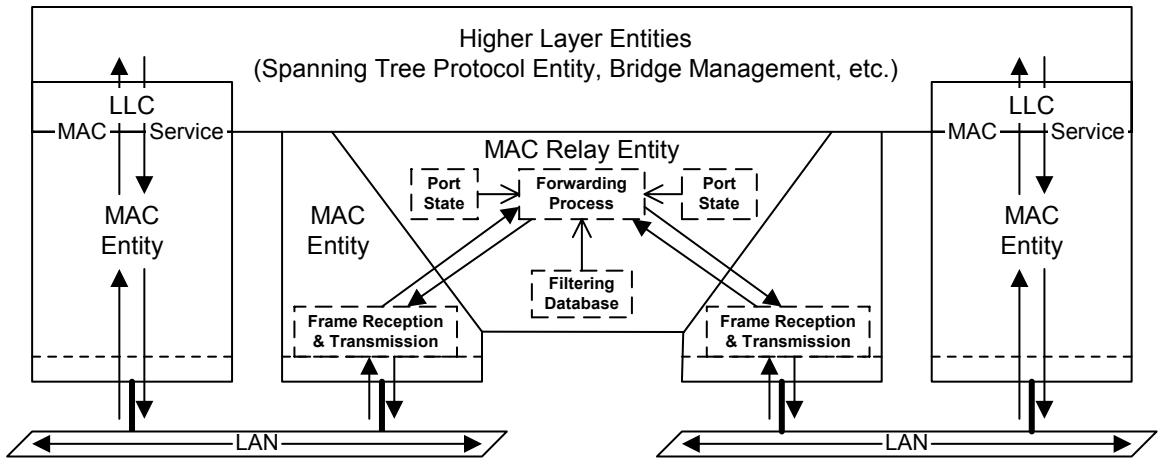
Figure 8-10—Logical points of attachment of the Higher Layer and Relay Entities
Figure 8-11 depicts the information used to control the forwarding of frames from one Bridge Port to another (the Port States and the content of the Filtering Database) as a series of switches (shown in the open, disconnected state) inserted in the path provided by the MAC Relay Entity. For the Bridge to forward a given frame between two Ports, all three switches must be in the closed state. While showing Higher Layer Entities sharing the point of attachment to each LAN used by each Bridge Port to forward frames, this figure further illustrates a point made by Figure 8-10. Controls placed in the forwarding path have no effect on the ability of a Higher Layer Entity to transmit and receive frames to or from a given LAN using a direct attachment to that LAN (e.g., from entity A to LAN A); they only affect the path taken by any indirect transmission or reception (e.g., from entity A to or from LAN B).
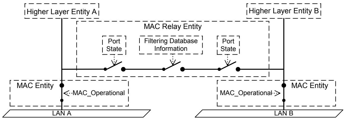
Figure 8-11—Effect of control information on the forwarding path
The functions provided by Higher Layer Entities can be categorized as requiring either
a) A single point of attachment to the Bridged Local Area Network, providing connectivity to stations attached to the network at any point (subject to administrative control), as does Bridge Management; or
b) A distinct point of attachment to each individual LAN attached by a Bridge Port, providing connectivity only to peer entities connected directly to that LAN, as do the Spanning Tree Protocol Entity and the GARP Entity.
In the latter case, it is essential that the function associate each received and transmitted frame with a point of attachment. Frames transmitted or received via one point of attachment are not to be relayed to and from other Ports and attached LANs, so the MAC Addresses (8.13.4) used to reach these functions are permanently configured in the Filtering Database.
NOTE 1 —Addresses used to reach functions with distinct points of attachment are generally group MAC Addresses.
NOTE 2—A single higher layer entity can incorporate both a function requiring a single point of attachment and a function requiring distinct points of attachment. The two functions are reached using different MAC addresses.
Figure 8-12 illustrates forwarding path connectivity for frames destined for Higher Layer Entities requiring per-Port points of attachment. Configuration of the Permanent Database in all Bridges to prevent relay of frames addressed to these entities means that they receive frames only via their direct points of attachment (i.e., from LAN A to entity A, and from LAN B to entity B), regardless of Port states.
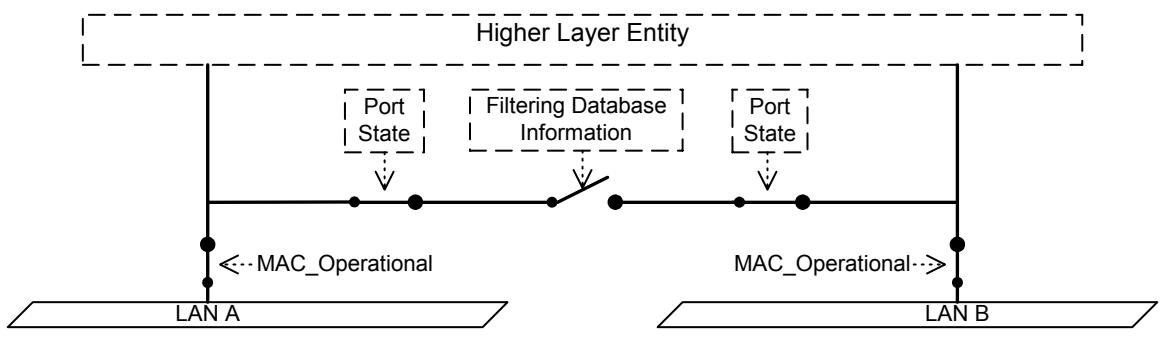
Figure 8-12—Per-Port points of attachment
Figure 8-13 and Figure 8-14 illustrate forwarding path connectivity for frames destined for a Higher Layer Entity requiring a single point of attachment. In both figures, the Filtering Database permits relay of frames, as do the Port states in Figure 8-13 where frames received from LAN B are relayed by the Bridge to the entity and to LAN A.
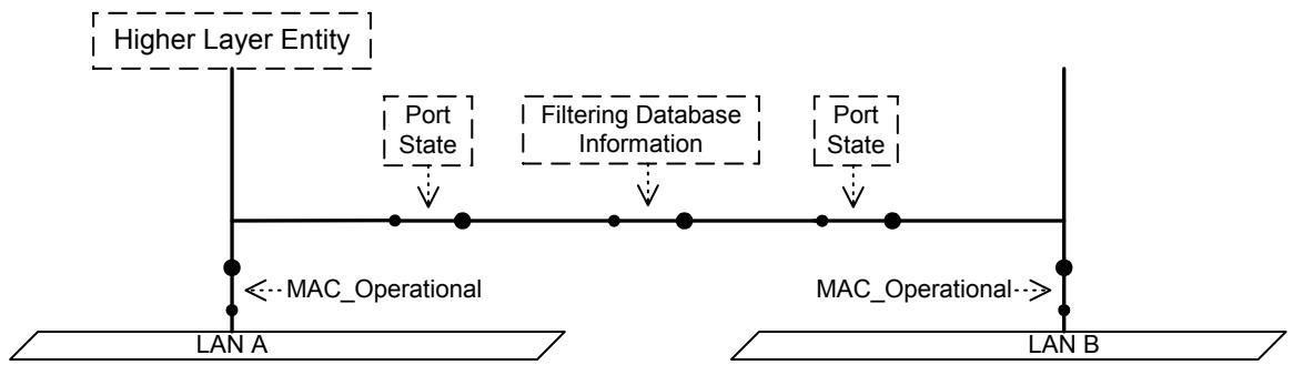
Figure 8-13—Single point of attachment—relay permitted
Figure 8-14—Single point of attachment—relay not permitted
In Figure 8-14, frames received from LAN A are received by the entity directly, but frames received from LAN B are not relayed by the Bridge and will only be received by the entity if another forwarding path is provided between LANs A and B. If the Discarding Port state shown resulted from spanning tree computation (and not from disabling the Administrative Bridge Port State), such a path will exist via one or more Bridges. If there is no active Spanning Tree path from B to A, the network has partitioned into two separate Bridged Local Area Networks, and the Higher Layer Entity shown is reachable only via LAN A.
Specific Higher Layer Entities can take notice of the Administrative Bridge Port State, as required by their specification. The Spanning Tree Protocol Entity is one such example—BPDUs are never transmitted or received on Ports with an Administrative Bridge Port State of Disabled.
If a Bridge Port's MAC Entity is not operational, a Higher Layer Entity directly attached at the Port will not be reachable, as Figure 8-15 illustrates. The Spanning Tree Protocol Entity ensures that the Port State is Discarding if the MAC_Operational (6.4.2) is FALSE even if the Administrative Bridge Port State is Enabled.
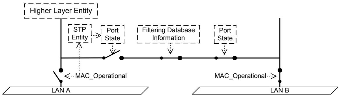
Figure 8-15—Effect of Port State
The connectivity provided to Higher Layer Entities and to the LANs that compose a Bridged Local Area Network can be further controlled by a Bridge Port operating as a network access port (IEEE Std 802.1X). The operation of Port-based access control has the effect of creating two distinct points of access to the LAN. One, the Uncontrolled Port, allows transmission and reception of frames to and from the attached LAN regardless of the authorization state; the other, the Controlled Port, only allows transmission following authorization. If the port is not authorized, the Spanning Tree Protocol Entity, which uses the Controlled Port (as does the MAC Relay Entity) will be unable to exchange BPDUs with other Bridges attached to LAN A, and will set the Bridge Port State to Discarding.
NOTE—If the Spanning Tree Protocol Entity was not aware of the Unauthorized state of the Port, and believed that it was transmitting and receiving BPDUs, it might assign a Bridge Port State of Forwarding. Following authorization a temporary loop in network connectivity might then be created.
Figure 8-16 illustrates the connectivity provided to Higher Layer Entities if the MAC entity is physically capable of transmitting and receiving frames; i.e., MAC_Operational is TRUE, but AuthControlledPortStatus is Unauthorized. Higher Layer Entity A and the PAE (the port access entity that operates the authorization protocol) are connected to the Uncontrolled Port and can transmit and receive frames using the MAC entity associated with the Port, which Higher Layer Entity B cannot. None of the three entities can transmit or receive to or from LAN B.
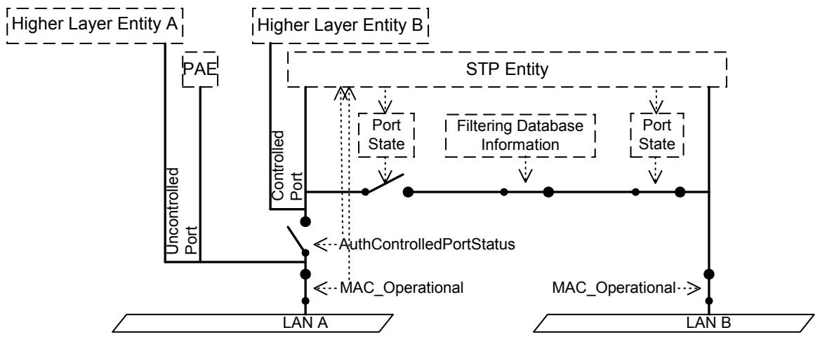
Figure 8-16—Effect of authorization
NOTE—The administrative and operational state values associated with the MAC, the Port's authorization state, and the Bridge Port State equate to the ifAdminStatus and ifOperStatus parameters associated with the corresponding interface definitions; see IETF RFC 2233 [B9].
8.13.10 VLAN attachment and connectivity for Higher Layer Entities
In VLAN-aware Bridges, two more switches appear in the forwarding path, corresponding to the actions taken by the Forwarding Process (8.6.2 and 8.6.4) in applying the ingress and egress rules (8.6.2 and 8.6.4), as illustrated in Figure 8-17.
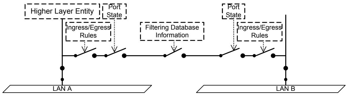
Figure 8-17—Ingress/egress control information in the forwarding path
As with Port state information, the configuration of the ingress and egress rules does not affect the reception of frames received on the same LAN as a Higher Layer Entity's point of attachment. For example, the reception of a frame by Higher Layer Entity A that was transmitted on LAN A is unaffected by the ingress or egress configuration of either Port. However, for Higher Layer Entities that require only a single point of attachment, the ingress and egress configuration affects the forwarding path. For example, frames destined for Higher Layer Entity A that are transmitted on LAN B would be subjected to the ingress rules that apply to Port B and the egress rules that apply to Port A.
The decision as to whether frames transmitted by Higher Layer Entities are VLAN-tagged or untagged depends on the Higher Layer Entity concerned and the connectivity that it requires
a) Spanning Tree BPDUs transmitted by the Spanning Tree Protocol Entity are not forwarded by Bridges and must be visible to all other Spanning Tree Protocol Entities attached to the same LAN. Such frames shall be transmitted untagged;
NOTE—Any BPDUs or GVRP PDUs that carry a tag header are not recognized as well-formed BPDUs or GVRP PDUs and are not forwarded by the Bridge.
b) The definition of the GVRP application (11.2.3) calls for all GVRP frames to be transmitted untagged for similar reasons;
c) The definition of the GMRP application (Clause 10) calls for all GMRP frames originating from VLAN-aware devices to be transmitted VLAN-tagged, in order for the VID in the tag to be used to identify the VLAN context in which the registration applies;
d) It may be necessary for PDUs transmitted for Bridge Management (8.12) to be VLAN-tagged in order to achieve the necessary connectivity for management in a Virtual Bridged Local Area Network. This is normally achieved by routing a packet containing the PDU to the routed subnet associated with the VLAN. Transmission of the packet through the router interface to that VLAN and subsequent forwarding of the resulting frame by VLAN-aware Bridges ensures that the frame is correctly VLAN-tagged, as required.
9 Tagged frame format
This clause specifies the format of the VLAN tags added to and removed from user data frames by the tag encoding and decoding functions that support the Enhanced Internal Sublayer Service (EISS, 6.6). It
a) Reviews the purpose of VLAN tagging, and the functionality provided;
b) Specifies generic rules for the representation of tag fields and their encoding in the octets of a MAC Service Data Unit (MSDU);
c) Specifies a general tag format, comprising a Tag Protocol Identifier (TPID), Tag Control Information (TCI), with additional information as signaled in the TCI, and;
d) Specifies the format of the TPID for each IEEE 802 media access control method;
e) Describes the types of VLAN tag that can be used;
f) Documents the allocation of Ethertype values to identify the types of tag specified in this standard;
g) Specifies the format of the TCI and additional information for each tag type.
Further analysis of the frame formats and the format translations that can occur when frames are tagged or untagged when relayed between different media access control methods can be found in Annex C.
9.1 Purpose of tagging
Tagging a frame with a VLAN tag:
a) Allows a VLAN Identifier (VID) to be conveyed, facilitating consistent VLAN classification of the frame throughout the network and enabling segregation of frames assigned to different VLANs;
b) Allows priority (6.4, 6.6) to be conveyed with the frame when using IEEE 802 LAN media access control methods that provide no inherent capability to signal priority;
c) Can support the use of differing media access control methods within a single network, by:
1) Signaling the bit order of MAC address information conveyed in the MSDU;
2) Signaling the presence or absence of an embedded routing information field (E-RIF) (6.6) carried in the MSDU of MAC types that provide no inherent capability to convey routing information.
9.2 Representation and encoding of tag fields
In this subclause, octets are numbered starting from 1 and increasing in the order in which they are encoded in the sequence of octets that comprise a MAC Service Data Unit (MSDU).
Where bits in consecutive octets are used to encode a binary number in a single field, the lower octet number encodes the more significant bits of the field, and the least significant bit of the lower octet number and the most significant bit of the next octet both form part of the field.
Where the value of a field comprising a sequence of octets is represented as a sequence of two-digit hexadecimal values separated by hyphens (e.g., A1-5B-03), the leftmost hexadecimal value (A1 in this example) appears in the lowest numbered octet of the field and the rightmost hexadecimal value (03 in this example) appears in the highest numbered octet of the field.
The bits in an octet are numbered from 1 to 8, where 1 is the least significant bit.
When the terms set and reset are used in the text to indicate the values of single-bit fields, set is encoded as a binary 1 and reset as a binary 0 (zero).
When the encoding of a field or a number of fields is represented using a diagram:
a) Octets are shown with the lowest numbered octet nearest the top of the page, the octet numbering increasing from the top to bottom; or
b) Octets are shown with the lowest numbered octet nearest the left of the page, the octet numbering increasing from left to right;
c) Within an octet, bits are shown with bit 8 to the left and bit 1 to the right.
9.3 Tag format
Each VLAN tag comprises the following sequential information elements:
a) A Tag Protocol Identifier (TPID) (9.4);
b) Tag Control Information (TCI) that is dependent on the tag type (9.5, 9.6);
c) Additional information, if and as required by the tag type and TCI.
The tag encoding function supports each EISS (6.6) instance by using an instance of the Internal Sublayer Service (ISS) to transmit and receive frames and encodes the above information in the first and subsequent octets of the MSDU that will accompany an ISS M_UNITDATA.request, immediately prior to encoding the sequence of octets that comprise the corresponding EISS M_UNITDATA.request's MSDU. On reception the tag decoding function is selected by the TPID and decodes the TCI and additional information octets (if present) prior to issuing an EISS M_UNITDATA.indication with an MSDU that comprises the subsequent octets.
9.4 Tag Protocol Identifier (TPID) formats
The TPID includes an Ethernet Type value that is used to identify the frame as a tagged frame and to select the correct tag decoding functions.
Where the ISS instance used to transmit and receive tagged frames is provided by a media access control method that can support Ethernet Type encoding directly (e.g., is an IEEE 802.3 or IEEE 802.11 MAC) or is media access method independent (e.g., 6.6), the TPID is Ethernet Type encoded, i.e., is two octets in length and comprises solely the assigned Ethernet Type value.
Where the ISS instance is provided by a media access method that cannot directly support Ethernet Type encoding (e.g., is an IEEE 802.5 or FDDI MAC), the TPID is encoded according to the rule for a Subnetwork Access Protocol (Clause 10 of IEEE Std 802) that encapsulates Ethernet frames over LLC, and comprises the SNAP header (AA-AA-03) followed by the SNAP PID (00-00-00) followed by the two octets of the assigned Ethernet Type value.
9.5 Tag Protocol Identification
A single type of tag is specified:
a) A VLAN TAG, for general use by Bridges (3.2).
A distinct Ethertype has been allocated (Table 9-1) for use in the TPID field (9.4) of each tag type so they can be distinguished from each other, and from other protocols.
Table 9-1—IEEE 802.1Q Ethernet Type allocations
<table><tr><td>Tag Type</td><td>Name</td><td>Value</td></tr><tr><td>VLAN TAG</td><td>IEEE Std 802.1Q Tag Protocol Type (802.1QTagType)</td><td>81-00</td></tr></table>
9.6 VLAN Tag Control Information
The VLAN TAG TCI field (Figure 9-1) is two octets in length and encodes the vlan_identifier and priority parameters of the corresponding EISS M_UNITDATA.request as unsigned binary numbers and a Canonical Format Indicator (CFI) as a single bit.
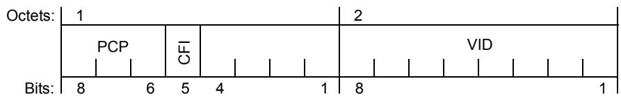
Figure 9-1—VLAN TAG TCI format
The VLAN Identifier is encoded in a 12-bit field. A VLAN-aware Bridge may not support the full range of VID values but shall support the use of all VID values in the range 0 through a maximum N, less than or equal to 4094 and specified for that implementation. Table 9-2 identifies VID values that have specific meanings or uses.
Table 9-2—Reserved VID values
<table><tr><td>VID value (hexadecimal)</td><td>Meaning/Use</td></tr><tr><td>0</td><td>The null VLAN ID. Indicates that the tag header contains only priority information; no VLAN identifier is present in the frame. This VID value shall not be configured as a PVID or a member of a VID Set, or configured in any Filtering Database entry, or used in any Management operation.</td></tr><tr><td>1</td><td>The default PVID value used for classifying frames on ingress through a Bridge Port. The PVID value of a Port can be changed by management.</td></tr><tr><td>FFF</td><td>Reserved for implementation use. This VID value shall not be configured as a PVID or a member of a VID Set, or transmitted in a tag header. This VID value may be used to indicate a wildcard match for the VID in management operations or Filtering Database entries.</td></tr></table>
NOTE 1—There is a distinction between the range of VIDs that an implementation can support and the maximum number of active VLANs supported at any one time. An implementation supports only 16 active VLANs, for example, may use VIDs chosen from anywhere in the identifier space, or from a limited range. The latter can result in difficulties where different Bridges in the same network support different maximums. It is recommended that new implementations of this standard support the full range of VIDs, even if the number of active VLANs is limited.
The priority is conveyed in the 3-bit Priority Code Point (PCP) field.
If the CFI is reset, all MAC Address information that may be present in the MSDU is in Canonical format and the tag comprises solely the TPID and TCI fields, i.e., the tag does not contain an Embedded Routing Information Field (E-RIF).
The information conveyed by a CFI bit that is set depends on the media access control method that directly provides the ISS instance used by the tagging or detagging function, as follows:
a) If the TPID is Ethernet Type encoded (IEEE 802.3, IEEE 802.11, or media access method independent provision), an E-RIF (9.7) follows the TCI. The NCFI bit in the E-RIF is reset if MAC address information present in the MSDU is in Canonical format and set otherwise (Non-canonical format).
b) If an IEEE 802.5 MAC is used, all MAC Address information present in the MSDU is in Non-canonical format.
c) If an FDDI MAC is used and the frame is source routed (i.e., the RII bit in the frame's source MAC Address field is set indicating that a RIF follows the source MAC Address), all MAC Address information present in the MSDU is in Non-canonical format.
d) If an FDDI MAC is used and the frame is not source routed (i.e., the RII bit in the frame's source MAC Address field is reset), an E-RIF (9.7) follows the TCI as for item a).
NOTE 2—A decision to use native source-routing on FDDI or to use an embedded routing information field in the VLAN tag depends on local knowledge in a Bridge or end station of the capabilities of the other stations attached to the FDDI LAN. The VLAN tag E-RIF allows source-routing information to be transparently “tunneled” across LANs that do not support source routing and through MAC Bridges and VLAN-aware Bridges that discard native source-routed frames.
NOTE 3—An E-RIF is never present when the ISS is directly provided by an IEEE 802.5 MAC.
The ability to support translation of embedded MAC Addresses between Canonical and Non-canonical formats (and vice versa) when transmitting an untagged frame is not required by this standard. In Bridges that do not support such translation capability on a given outbound Port, frames that may require such translation before being forwarded as untagged frames on that Port shall be discarded.
NOTE 4—The CFI field of the TCI was required for historical reasons, in order to support media where MAC addresses were carried as data in Non-canonical format. New implementations should not attempt to support user communication that would require the addition of a tag with the CFI bit set to a frame; most Bridges will discard frames with this bit set that are to be forwarded untagged, as permitted by this subclause. Conformance in respect of receipt of frames with this bit set remains unchanged from previous revisions of this standard.
9.7 Embedded Routing Information Field (E-RIF)
The E-RIF that can appear in a VLAN tag may be used to encode the rif_information parameter of the corresponding EISS M_UNITDATA.request and is a modification of the RIF as defined in C3.3.2 of IEEE Std 802.1D. It comprises
a) A two-octet Route Control Field (RC) (Figure 9-2) that comprises the following fields:
1) Routing Type (RT);
2) Length (LTH);
3) Direction Bit (D);
4) Largest Frame (LF);
5) Non-canonical Format Indicator (NCFI), set to indicate that all MAC Address information that may be present in the frames MSDU is in Canonical format, and reset otherwise.
b) Zero or more octets of Route Descriptors (up to a maximum of 28 octets), as defined by the Route Control Field.
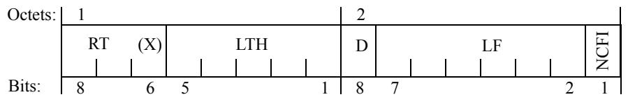
Figure 9-2—E-RIF Route Control (RC) field
The structure and semantics associated with the RT, LTH, D, LF, and Route Descriptor fields are as defined in C3.3.2 of IEEE Std 802.1D, with the following exceptions.
On receipt of an EISS M_UNITDATA.request without a rif_information parameter (or with a null rif_information parameter), with the canonical_format_indicator parameter False, a tagging function that uses an FDDI MAC shall encode an RT value of 010 to indicate a transparent frame, i.e., a frame that does not use the media access method dependent capabilities of any particular MAC to carry routing information and shall encode 00000 in the LTH to indicate that zero octets of Route Descriptor follow.
10 Use of GMRP in VLANs
The GARP Multicast Registration Protocol, GMRP, defined in Clause 10 of IEEE Std 802.1D, allows the declaration and dissemination of Group membership information, in order to permit GMRP-aware Bridges to filter frames destined for group MAC Addresses on Ports through which potential recipients of such frames cannot be reached. The specification in IEEE Std 802.1D calls for the propagation of GMRP registrations only in the GARP Information Propagation (GIP) Context known as the Base Spanning Tree Context (Clause 10 and 12.3.4 of IEEE Std 802.1D); i.e., propagation of GMRP information occurs among the set of Ports of a Bridge that are part of the active topology (7.4 of IEEE Std 802.1D) of the Spanning Tree resulting from operation of the Spanning Tree Algorithm and Protocol defined in IEEE Std 802.1D, 1998 Edition, Clause 8, and/or the Rapid Spanning Tree Protocol (RSTP) defined in Clause 17 of IEEE Std 802.1D. This GIP Context is identified by a GIP Context Identifier of 0.
In network environments that support the definition and management of VLANs in accordance with this standard, the operation of GMRP as specified in IEEE Std 802.1D is extended to permit GMRP to operate in multiple GIP contexts, defined by the set of VLANs that are active in the network; these are known as VLAN Contexts.
The use of GMRP in a VLAN Context allows GMRP registrations to be made that are specific to that VLAN; i.e., it allows the Group filtering behavior for one VLAN to be independent of the Group filtering behavior for other VLANs. The following subclauses define the extensions to the definition of GMRP that permit its use in VLAN contexts.
With the exception of the extensions defined in this standard, the operation of GMRP and the conformance requirements associated with GMRP are as defined in IEEE Std 802.1D.
10.1 Definition of a VLAN Context
The GIP Context Identifier used to identify a VLAN Context shall be equal to the VID used to identify the corresponding VLAN.
The set of Ports of a Bridge defined to be part of the active topology for a given VLAN Context shall be equal to the set of Ports of a Bridge for which the following are true:
a) The Port is a member of the member set (8.8.9) for that VLAN; and
b) The Port is one of the Ports of the Bridge that are part of the active topology for the spanning tree that supports that VLAN.
NOTE—This definition applies equally to SST and MST environments. It ensures that GMRP operates in either environment, without the GMRP implementations needing to be aware whether the VLAN contexts that apply are all supported by the same spanning tree, as in the SST environment, or are potentially distributed across two or more spanning trees, as in the MST environment.
10.2 GMRP Participants and GIP Contexts
For each Port of the Bridge, a distinct instance of the GMRP Participant can exist for each VLAN Context supported by the Bridge. Each GMRP Participant maintains its own set of GARP Applicant and Registrar state machines and its own Leave All state machine. No GMRP Participant is associated with the Base Spanning Tree Context.
A given GARP Participant, operating in a given GIP Context, manipulates only the Port Filtering Mode and Group Registration Entry information for the context concerned. In the case of Group Registration Entries, the GIP Context Identifier value corresponds to the value of the VID field of the entry.
10.3 Context identification in GMRP PDUs
Implementations of GMRP conformant to the specification of GMRP in IEEE Std 802.1D exchange PDUs in the Base Spanning Tree Context; such PDUs are transmitted and received by GMRP Participants as untagged frames.
Implementations of GMRP in Bridges apply the same ingress rules (8.6.2) to received GMRP PDUs that are defined for the reception Port. Therefore
a) GMRP frames with no VLAN classification (i.e., untagged or priority-tagged GMRP frames) are discarded if the Acceptable Frame Types parameter (6.7) for the Port is set to Admit Only VLAN-tagged frames. Otherwise, they are classified according to the PVID for the Port;
b) VLAN-tagged GMRP frames are classified according to the VID carried in the tag header;
c) If Ingress Filtering (8.6.2) is enabled, and if the Port is not in the member set (8.8.9) for the GMRP frame's VLAN classification, then the frame is discarded.
d) If the VLAN classification of the frame is outside the range of VIDs supported by the implementation, then the frame is discarded.
The VLAN classification thus associated with received GMRP PDUs establishes the VLAN Context for the received PDU and identifies the GARP Participant instance to which the PDU is directed.
GMRP PDUs transmitted by GMRP Participants are VLAN classified according to the VLAN Context associated with that Participant. GMRP Participants in Bridges apply the same egress rules that are defined for the transmission Port (8.6.4). Therefore
e) GMRP PDUs are transmitted through a given Port only if the value of the member set for the Port for the VLAN concerned indicates that the VLAN is registered on that Port;
f) GMRP PDUs are transmitted as VLAN-tagged frames or as untagged frames in accordance with the state of the untagged set (8.8.2) for that Port for the VLAN concerned. Where VLAN-tagged frames are transmitted, the VID field of the tag header carries the VLAN Context Identifier value.
NOTE—As part of Project P802.1ak, the functionality of the multicast registration protocol will be enhanced to include the ability to propagate wild-card group entries.
10.4 Default Group filtering behavior and GMRP propagation
The propagation of GMRP registrations within a VLAN context has implications with respect to the choice of default Group filtering behavior within a network. As GMRP frames are transmitted only on outbound Ports that are in the member set (8.8.9) for the VLAN concerned, propagation of Group registrations by a given Bridge occurs only toward regions of the network where that VLAN has been (statically or dynamically) registered. This is illustrated in Figure 10-1; dotted lines in the diagram show those regions of the LAN where propagation of registrations for Group M in VLAN V does not occur. Consequently, the Filtering Databases of the lower two Bridges will not contain any Dynamic Group Registration Entry for Group M in VLAN V.
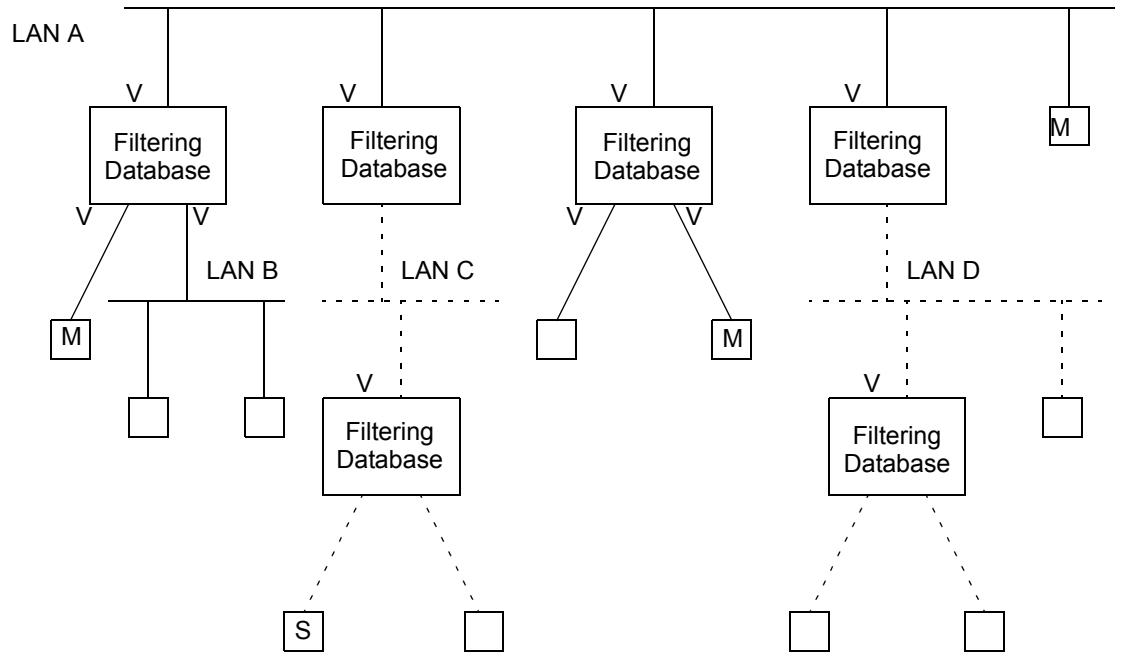
Filtering Database Bridge
M Applicant station that is a member of Group M in VLAN Context V
☐ Applicant station that is not a member of Group M
S End station transmitting frames to Group M on VLAN V
Regions of the LAN where registrations for Group M in VLAN Context V are not propagated
Figure 10-1—Example of GMRP propagation in a VLAN context
The action of these two Bridges on receipt of frames, on either of their lower Ports, destined for Group M and VLAN V, will depend on the Default Group Filtering Behavior adopted by their upper Ports, which are the Ports that are in the member set for VLAN V. If the Default Group Filtering Behavior is either Forward All Groups or Forward Unregistered Groups, then these Bridges will forward the frames. If the Default Group Filtering Behavior is Filter Unregistered Groups, then these Bridges will filter the frames. In the scenario shown, the choice of Default Group Filtering Behavior is therefore crucial with respect to whether or not end station S, or any other station that is “outside” the VLAN, is able to send frames to members of the Group. The choice between Filter Unregistered Groups and the other default behaviors, therefore, has the effect of defining VLANs that are closed to external unregistered traffic (Filter Unregistered Groups) or open to external unregistered traffic (Either of the other default behaviors).
11 VLAN topology management
The egress rules (8.6.4) defined for the Forwarding Process in Bridges rely on the existence of configuration information for each VLAN that defines the set of Ports of the Bridge through which one or more members are reachable. This set of Ports is known as the member set (8.8.9), and its membership is determined by the presence or absence of configuration information in the Filtering Database, in the form of Static and Dynamic VLAN Registration Entries (8.8.2, 8.8.5).
Reliable operation of the VLAN infrastructure requires VLAN membership information held in the Filtering Database to be maintained in a consistent manner across all VLAN-aware Bridges in the network, in order to ensure that frames destined for end station(s) on a given VLAN can be correctly delivered, regardless of where in the network the frame is generated. Maintenance of this information by end stations that are sources of VLAN-tagged frames can allow such stations to suppress transmission of such frames if no members exist for the VLAN concerned.
This standard defines the following mechanisms that allow VLAN membership information to be configured:
a) Dynamic configuration and distribution of VLAN membership information by means of the GARP VLAN Registration Protocol (GVRP), as described in 11.2;
b) Static configuration of VLAN membership information via Management mechanisms, as described in Clause 12, which allow configuration of Static VLAN Registration Entries.
These mechanisms provide for the configuration of VLAN membership information as a result of
c) Dynamic registration actions taken by end stations or Bridges in the network;
d) Administrative actions.
11.1 Static and dynamic VLAN configuration
The combined functionality provided by the ability to configure Static VLAN Registration Entries in the Filtering Database, coupled with the use of the Restricted_VLAN_Registration control (11.2.3.2.3) and the ability of GVRP to dynamically create and update Dynamic VLAN Registration Entries, offers the following possibilities with respect to how VLANs are configured on a given Port:
a) Static configuration only. The management facilities described in Clause 12 are used to establish precisely which VLANs have this Port in their member set, and the GVRP management controls are used to disable the operation of the GVRP protocol on that Port. Hence, any use of GVRP by devices reachable via that Port is ignored, and the member set for all VLANs can therefore only be determined by means of static entries in the Filtering Database.
b) Dynamic configuration only. The operation of GVRP is relied on to establish Dynamic VLAN Registration Entries that will dynamically reflect which VLANs are registered on the Port, their contents changing as the configuration of the network changes. The GVRP management controls are set to enable the operation of the GVRP protocol on that Port.
c) Combined static and dynamic configuration. The static configuration mechanisms are used in order to configure some VLAN membership information; for other VLANs, GVRP is relied on to establish the configuration. The GVRP management controls are set to enable the operation of the GVRP protocol on that Port.
All of these approaches are supported by the mechanisms defined in this standard, and each approach is applicable in different circumstances. For example
d) Use of static configuration may be appropriate on Ports where the configuration of the attached devices is fixed, or where the network administrator wishes to establish an administrative boundary outside of which any GVRP registration information is to be ignored. For example, it might be desirable for all Ports serving end user devices to be statically configured in order to ensure that particular end users have access only to particular VLANs.
e) Use of dynamic configuration may be appropriate on Ports where the VLAN configuration is inherently dynamic; where users of particular VLANs can connect to the network via different Ports on an ad hoc basis, or where it is desirable to allow dynamic reconfiguration in the face of Spanning Tree topology changes. In particular, if the “core” of the network contains redundant paths that are pruned by the operation of Spanning Tree, then it is desirable for Bridge Ports that form the core network to be dynamically configured.
f) Use of both static and dynamic configuration may be appropriate on Ports where it is desirable to place restrictions on the configuration of some VLANs, while maintaining the flexibility of dynamic registration for others. For example, on Ports serving mobile end user devices, this would maintain the benefits of dynamic VLAN registration from the point of view of traffic reduction, while still allowing administrative control over access to some VLANs via that Port.
11.2 GARP VLAN Registration Protocol
The GARP VLAN Registration Protocol (GVRP) defines a GARP Application that provides the VLAN registration service defined in 11.2.2. GVRP makes use of GARP Information Declaration (GID) and GARP Information Propagation (GIP), which provide the common state machine descriptions and the common information propagation mechanisms defined for use in GARP-based applications. The GARP architecture, GID, and GIP are defined in Clause 12 of IEEE Std 802.1D.
GVRP provides a mechanism for dynamic maintenance of the contents of Dynamic VLAN Registration Entries for each VLAN, and for propagating the information they contain to other Bridges. This information allows GVRP-aware devices to dynamically establish and update their knowledge of the set of VLANs that currently have active members, and through which Ports those members can be reached.
11.2.1 GVRP overview
The operation of GVRP is closely similar to the operation of GMRP (Clause 10 of IEEE Std 802.1D), which is used for registering Group membership information. The primary differences are as follows:
a) The attribute values carried by the protocol are 12-bit VID values, rather than 48-bit MAC Addresses and Group service requirement information;
b) The act of registering/deregistering a VID affects the contents of Dynamic VLAN Registration Entries (8.8.5), rather than the contents of Group Registration Entries (8.8.4).
c) In an SST environment, there is a single GVRP Participant per port, rather than one GVRP Participant per VLAN per port, and the GVRP Participants all operate in a single GIP context;
d) In an MST environment, there is again a single GVRP Participant per port, but each GVRP Participant operates in multiple GIP contexts.
GVRP allows both end stations and Bridges in a network to issue and revoke declarations relating to membership of VLANs. The effect of issuing such a declaration is that each GVRP Participant that receives the declaration will create or update a Dynamic VLAN Registration Entry in the Filtering Database to indicate that VLAN is registered on the reception Port. Subsequently, if all Participants on a segment that had an interest in a given VID revoke their declarations, the Port attached to that segment is set to
Unregistered in the Dynamic VLAN Registration Entry for that VLAN by each GVRP Participant attached to that segment.
Figure 11-1 illustrates the architecture of GVRP in the case of a two-Port Bridge and an end station.
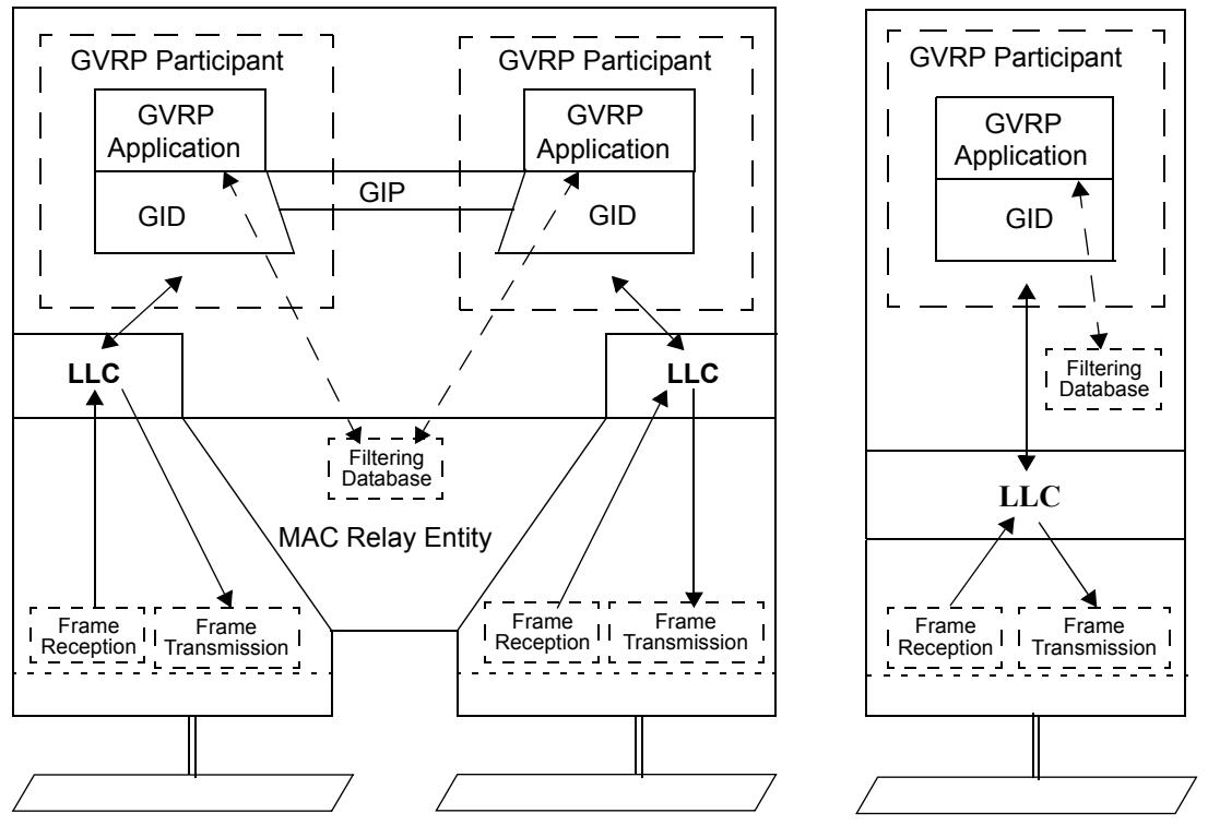
Figure 11-1—Operation of GVRP
As shown in Figure 11-1, the GVRP Participant consists of the following components:
e) The GVRP Application, described in 11.2.3;
f) GARP Information Propagation (GIP), described in Clause 12 of IEEE Std 802.1D;
g) GARP Information Declaration, described in Clause 12 of IEEE Std 802.1D.
11.2.1.1 Behavior of end stations
VLAN-aware end stations participate in GVRP protocol activity, as appropriate for the set of VLANs of which they are currently members. GVRP provides a way for such an end station to ensure that the VLAN(s) of which it is a member are registered for each Port on any LAN segment to which the end station is attached. GVRP also provides for that VID information to be propagated across the Spanning Tree to other VLAN-aware devices, as described in 11.2.1.2.
Incoming VLAN membership information (from all other devices on the same LAN segment) allows such end stations to “source prune” (i.e., discard at source; see 10.2.2 of IEEE Std 802.1D) any traffic destined for VLANs that currently have no other members in the network, thus avoiding the generation of unnecessary traffic on their local LAN segments. This is illustrated in Figure 11-1 by a Filtering Database shown as being present in the end station.
NOTE—Non-VLAN-aware end stations have no need to register VLAN membership via GVRP; indeed, this would be impossible for them to achieve if truly VLAN-unaware, as they would have no knowledge of the set of VLANs in which they participate. Their VLAN registration requirements are taken care of by means of the configuration of PVIDs (and possibly other VLAN classification mechanisms) and the propagation of registered VLAN IDs by the Bridges.
11.2.1.2 Behavior of Bridges
VLAN-aware Bridges register and propagate VLAN memberships on all Bridge Ports that are part of the active topology of the underlying Spanning Tree(s). Incoming VID registration and de-registration information is used to update the Dynamic VLAN Registration Entries associated with each VLAN. Any changes in the state of registration of a given VID on a given Port are propagated on Ports that are part of the active topology of the underlying Spanning Tree, in order to ensure that other GVRP-aware devices in the network update their Filtering Databases appropriately. In Bridges that support multiple Spanning Tree instances, the MST Configuration Table (12.12, 13.7) is used to determine which spanning tree instance is to be used to propagate registration information for each supported VLAN.
The Filtering Databases in all GVRP-aware devices are thus automatically configured such that the Port Map in the Dynamic VLAN Registration Entry for a given VID indicates that a given Port is registered if one or more members of the corresponding VLAN are reachable through the Port.
NOTE—The information that determines whether frames destined for each VLAN are transmitted VLAN-tagged or untagged is carried in Static VLAN Registration Entries (8.8.2); if no such entry exists for a VLAN, then it is assumed that frames for that VLAN are transmitted VLAN-tagged on all Ports. Therefore, if the configuration information held in the Filtering Database for a given VLAN consists only of information configured by the operation of GVRP (i.e., only a Dynamic VLAN Registration Entry), then all traffic for that VLAN will be VLAN-tagged on transmission.
11.2.1.3 Use of the PVID and VID Set
The initial state of the Permanent Database contains a Static VLAN Registration Entry for the Default PVID, in which the Port Map indicates Registration Fixed on all Ports. This ensures that in the default state, where the value of every PVID of each Port is the Default PVID and where the VID Set of each Port is empty, membership of the Default PVID is propagated across the network to all other GVRP-aware devices. Subsequent management action may change both the Permanent Database and the Filtering Database in order to modify or remove this initial setting and may change the PVID and/or VID Set value(s) on any Port of the Bridge.
NOTE—In the absence of any modification of these initial settings, this initial state ensures that connectivity is established across the network for the VLAN corresponding to the Default PVID.
11.2.2 VLAN registration service definition
The VLAN registration service allows MAC Service users to indicate to the MAC Service provider the set of VLANs in which they wish to participate; i.e., that the MAC Service user wishes to receive traffic destined for members of that set of VLANs. The service primitives allow the service user to
a) Register membership of a VLAN;
b) De-register membership of a VLAN.
Provision of these services is achieved by means of GVRP and its associated procedures, as described in 11.2.3.
$$
\text { ES\_REGISTER\_VLAN\_MEMBER (VID) }
$$
Indicates to the MAC Service provider that the MAC Service user wishes to receive frames destined for the VLAN identified by the VID parameter.
ES_DEREGISTER_VLAN_MEMBER (VID)
Indicates to the MAC Service provider that the MAC Service user no longer wishes to receive frames destined for the VLAN identified by the VID parameter.
The use of these services can result in the propagation of VID information across the Spanning Tree, affecting the contents of Dynamic VLAN Registration Entries (8.8.5) in Bridges and end stations in the network, and thereby affecting the frame forwarding behavior of those Bridges and end stations.
11.2.3 Definition of the GVRP Application
11.2.3.1 Definition of GARP protocol elements
11.2.3.1.1 GVRP Application address
The group MAC Address used as the destination address for GARP PDUs destined for GVRP Participants shall be the GVRP address identified in Table 11-1. Received PDUs that are constructed in accordance with the PDU format defined in 12.11 of IEEE Std 802.1D, and which carry a destination MAC Address equal to the GVRP address, are processed as follows:
a) In Bridges and end stations that support the operation of GVRP, all such PDUs shall be submitted to the GVRP Participant associated with the receiving Port for further processing;
b) In Bridges that do not support the operation of GVRP, all such PDUs shall be submitted to the Forwarding Process.
Table 11-1—GVRP Application address
<table><tr><td>Assignment</td><td>Value</td></tr><tr><td>GVRP address</td><td>01-80-C2-00-00-21</td></tr></table>
NOTE—The GVRP Application Address has been allocated from the set of GARP Application addresses defined in Table 12-1 of IEEE Std 802.1D, using the MAC Address contained in the second entry of that table.
11.2.3.1.2 Encoding of GVRP Attribute Types
The operation of GVRP defines a single Attribute Type (12.11.2.2 of IEEE Std 802.1D) that are carried in GARP protocol exchanges; the VID Attribute Type. The VID Attribute Type is used to identify values of VLAN Identifiers (VIDs). The value of the Group Attribute Type carried in GVRP PDUs shall be 1.
11.2.3.1.3 Encoding of GVRP Attribute Values
Values of instances of the VID Attribute Type shall be encoded as Attribute Values in GARP PDUs (12.11.2.6 of IEEE Std 802.1D) as two octets, taken to represent an unsigned binary number, and equal to the hexadecimal value of the VLAN identifier that is to be encoded.
11.2.3.2 Provision and support of the VLAN registration service
11.2.3.2.1 End system VLAN membership declaration
The GVRP Application element of a GVRP Participant provides the dynamic registration and de-registration services defined in 11.2.2, as follows:
On receipt of an ES_REGISTER_VLAN_MEMBER service primitive, the GVRP Participant issues a GID_Join.request service primitive (12.3.2.1 of IEEE Std 802.1D). The attribute_type parameter of the request carries the value of the VID Attribute Type (11.2.3.1.2), and the attribute_value parameter carries the value of the VID parameter carried in the ES_REGISTER_VLAN_MEMBER primitive.
On receipt of an ES_DEREGISTER_VLAN_MEMBER service primitive, the GVRP Participant issues a GID_Leave.request service primitive (12.3.2.1 of IEEE Std 802.1D). The attribute_type parameter of the request carries the value of the VID Attribute Type (11.2.3.1.2), and the attribute_value parameter carries the value of the VID parameter carried in the ES_REGISTER_VLAN_MEMBER primitive.
11.2.3.2.2 VLAN membership registration
The GVRP Application element of a GVRP Participant responds to registration and de-registration events signaled by GID as follows:
On receipt of a GID_Join.indication (12.3.2.2 of IEEE Std 802.1D) whose attribute_type is equal to the value of the VID Attribute Type (11.2.3.1.2), the GVRP Application element indicates the reception Port as Registered in the Port Map of the Dynamic VLAN Registration Entry for the VID indicated by the attribute_value parameter. If no such entry exists, there is sufficient room in the Filtering Database, and the VID is within the range of values supported by the implementation (see 9.6), then an entry is created. If not, then the indication is not propagated and the registration fails.
The creation of new Dynamic VLAN Registration Entries can be restricted by use of the Restricted_VLAN_Registration control (11.2.3.2.3). If the value of this control is TRUE, then creation of a new dynamic entry is permitted only if there is a Static VLAN Registration Entry for the VLAN concerned, in which the Registrar Administrative Control value is Normal Registration.
On receipt of a GID_Join.indication (12.3.2.2 of IEEE Std 802.1D) whose attribute_type is equal to the value of the VID Attribute Type (11.2.3.1.2), the GVRP Application element indicates the reception Port as Registered in the Port Map of the Dynamic VLAN Registration Entry for the VID indicated by the attribute_value parameter. If no such entry exists, there is sufficient room in the Filtering Database, and the VID is within the range of values supported by the implementation (see 9.6), then an entry is created. If not, then the indication is not propagated and the registration fails.
11.2.3.2.3 Administrative controls
The provision of static control over the declaration or registration state of the state machines associated with the GVRP Application is achieved by means of the Registrar Administrative Control parameters provided by GARP (12.9.1 of IEEE Std 802.1D). These parameters are represented as Static VLAN Registration Entries in the Filtering Database (8.8.2). Where management capability is implemented, these parameters can be manipulated by means of the management functionality defined in 12.7.
The provision of static control over the ability of Applicant state machines to participate in protocol exchanges is achieved by means of the Applicant Administrative Control parameters associated with the operation of GARP (12.9.2 of IEEE Std 802.1D). Where management capability is implemented, the Applicant Administrative Control parameters can be applied and modified by means of the management functionality defined in 12.9.
Further administrative control over dynamic VLAN registration can be achieved, if supported, by means of a per-Port Restricted_VLAN_Registration control parameter. If the value of this control is TRUE for a given Port, the creation or modification of Dynamic VLAN Registration Entries as a result of GVRP exchanges on that Port shall be restricted only to those VLANs for which Static VLAN Registration Entries exist in which the Registrar Administrative Control value is Normal Registration. If the value of the Restricted_VLAN_Registration control is FALSE, dynamic VLAN registration is not so restricted. The recommended default value of this parameter is FALSE. Where management capability is implemented, the value of the Restricted_VLAN_Registration control can be manipulated by means of the management functionality defined in 12.10. If management of this parameter is not supported, the value of this parameter shall be FALSE for all Ports.
11.2.3.3 GIP context for GVRP
In an SST environment, GVRP operates in the Base Spanning Tree Context (12.3.4 of IEEE Std 802.1D); i.e., GVRP operates only on the CIST defined by IEEE Std 802.1D. Consequently, all GVRP PDUs sent and received by GVRP Participants in SST bridges are transmitted as untagged frames.
11.2.3.4 GIP contexts for GVRP in MST environments
In an MST environment, GVRP operates in multiple spanning-tree contexts, one for each of the spanning trees. Each spanning-tree context consists of the ports that are in the forwarding state for the corresponding spanning tree. The GIP context for the GVRP Participants associated with a given spanning tree is the same as the spanning-tree context. MST bridges can identify the GIP contexts using the mappings of VID values to MSTID values (see 8.9.2). All GVRP PDUs sent and received by GVRP Participants in MST bridges are transmitted as untagged frames.
11.3 Conformance to GVRP
This subclause defines the conformance requirements for implementations claiming conformance to GVRP. Two cases are covered; implementation of GVRP in MAC Bridges and implementation of GVRP in end stations. Although this standard is principally concerned with defining the requirements for MAC Bridges, the conformance requirements for end station implementations of GVRP are included in order to give useful guidance to such implementations. The PICS proforma defined in Annex A is concerned only with conformance claims with respect to MAC Bridges.
11.3.1 Conformance to GVRP in MAC Bridges
A MAC Bridge for which conformance to GVRP is claimed shall
a) Conform to the operation of the GARP Applicant and Registrar state machines, and the LeaveAll generation mechanism, as defined in 12.8.1, 12.8.2, and 12.8.3 of IEEE Std 802.1D;
b) Exchange GARP PDUs as required by those state machines, formatted in accordance with the generic PDU format described in 12.11 of IEEE Std 802.1D, and able to carry application-specific information as defined in 11.2.3, using the GVRP Application address as defined in Table 11-1;
c) Propagate registration information
1) In an SST bridge, in accordance with the operation of GIP for the Base Spanning Tree Context, as specified in 12.3.3 and 12.3.4 of IEEE Std 802.1D; or
2) In an MST bridge, in accordance with the operation of GIP for multiple Spanning Tree contexts as specified in 11.2.3.4 of this standard.
d) Implement the GVRP Application component as defined in 11.2;
e) Forward, filter, or discard MAC frames carrying any GARP Application address as the destination MAC Address in accordance with the requirements of 8.13.6.
11.3.2 Conformance to GVRP in end stations
An end station for which conformance to GVRP is claimed shall
a) Conform to the operation of one of
1) The Applicant state machine, as defined in 12.8.1 of IEEE Std 802.1D; or
2) The Applicant Only state machine, as defined in 12.8.5 of IEEE Std 802.1D; or
3) The Simple Applicant state machine, as defined in 12.8.6 of IEEE Std 802.1D;
b) Exchange GARP PDUs as required by the GARP state machine(s) implemented, formatted in accordance with the generic PDU format described in 12.11 of IEEE Std 802.1D, and able to carry application-specific information as defined in 11.2.3, using the GVRP Application address as defined in Table 11-1;
c) Support the provision of end system registration and de-registration as defined in 11.2;
d) Discard MAC frames carrying any GARP Application address as the destination MAC Address in accordance with the requirements of 8.13.6.
An end station for which conformance to GVRP is claimed may optionally
e) Conform to the operation of the GARP Registrar state machine and the LeaveAll generation mechanism, as defined in 12.8.2 and 12.8.3 of IEEE Std 802.1D; and
f) Support the provision of VLAN registration and de-registration as defined in 11.2; and
g) Filter outgoing frames destined for group MAC Addresses in accordance with registered VLAN membership information, in a manner consistent with the operation of the filtering function of the forwarding process described in 8.6.3 and the operation of the egress rules defined in 8.6.4.
It is recommended that only those end stations that require the ability to perform Source Pruning (11.2.1.1) conform to the operation of the Applicant state machine (12.8.1 of IEEE Std 802.1D).
For the reasons stated in 12.7.9 of IEEE Std 802.1D, it is recommended that end stations that do not require the ability to perform Source Pruning implement the Applicant Only state machine (12.8.5 of IEEE Std 802.1D), in preference to the Simple Applicant state machine (12.8.6 of IEEE Std 802.1D).
NOTE—End stations that implement only item a2) and item b) through item d) are equivalent to the description of the Applicant Only Participant (12.7.7 of IEEE Std 802.1D); those that implement item a3) and item b) through item d) are equivalent to the description of the Simple Applicant Participant (12.7.8 of IEEE Std 802.1D). Such end stations require only the ability to register membership of one or more VLANs and revoke that membership at some later point in time; for this reason, there is no requirement to support the operation of the Registrar or Leave All state machines.
End stations that implement item a1) and item b) through item g) are able to perform “source pruning” as described in 11.2.1.1, i.e., to suppress the transmission of frames destined for VLANs that currently have no membership. Consequently, such end stations need to support the full Applicant state machine, in combination with the Registrar and Leave All state machines.
11.4 Procedural model
In IEEE Std 802.1Q, 2003 Edition, this subclause provided an example implementation of GVRP. It contained no normative provisions and has been superseded by other ways of sharing implementation information.
12 Bridge management
This clause defines the set of managed objects, and their functionality, that allow administrative configuration of VLANs.
This clause
a) Introduces the functions of management to assist in the identification of the requirements placed on Bridges for the support of management facilities.
b) Establishes the correspondence between the Processes used to model the operation of the Bridge (8.3) and the managed objects of the Bridge.
c) Specifies the management operations supported by each managed object.
12.1 Management functions
Management functions relate to the users' needs for facilities that support the planning, organization, supervision, control, protection, and security of communications resources, and account for their use. These facilities may be categorized as supporting the functional areas of Configuration, Fault, Performance, Security, and Accounting Management. Each functional area is summarized in 12.1.1 through 12.1.5, together with the facilities commonly required for the management of communication resources, and the particular facilities provided in that functional area by Bridge Management.
12.1.1 Configuration Management
Configuration Management provides for the identification of communications resources, initialization, reset and close-down, the supply of operational parameters, and the establishment and discovery of the relationship between resources. The facilities provided by Bridge Management in this functional area are
a) The identification of all Bridges that together make up the network and their respective locations and, as a consequence of that identification, the location of specific end stations to particular individual LANs.
b) The ability to remotely reset, i.e., reinitialize, specified Bridges.
c) The ability to control the priority with which a Bridge Port transmits frames.
d) The ability to force a specific configuration of a spanning tree.
e) The ability to control the propagation of frames with specific group MAC Addresses to certain parts of the configured network.
f) The ability to identify the VLANs in use, and through which Ports of the Bridge and for which Protocols frames destined for a given VLAN may be received and/or forwarded.
12.1.2 Fault Management
Fault Management provides for fault prevention, detection, diagnosis, and correction. The facilities provided by Bridge Management in this functional area are
a) The ability to identify and correct Bridge malfunctions, including error logging and reporting.
12.1.3 Performance Management
Performance Management provides for evaluation of the behavior of communications resources and of the effectiveness of communication activities. The facilities provided by Bridge Management in this functional area are as follows:
a) The ability to gather statistics relating to performance and traffic analysis. Specific metrics include network utilization, frame forward, and frame discard counts for individual Ports within a Bridge.
12.1.4 Security Management
Security Management provides for the protection of resources. Bridge Management does not provide any specific facilities in this functional area.
12.1.5 Accounting Management
Accounting Management provides for the identification and distribution of costs and the setting of charges. Bridge Management does not provide any specific facilities in this functional area.
12.2 Managed objects
Managed objects model the semantics of management operations. Operations on an object supply information concerning, or facilitate control over, the Process or Entity associated with that object.
The managed resources of a MAC Bridge are those of the Processes and Entities established in 8.3 of this standard and IEEE Std 802.1D, 12.2. Specifically,
a) The Bridge Management Entity (12.4 and 8.12).
b) The individual MAC Entities associated with each Bridge Port (12.5, 8.2, and 8.5).
c) The Forwarding Process of the MAC Relay Entity (12.6, 8.2, and 8.6).
d) The Filtering Database of the MAC Relay Entity (12.7 and 8.8).
e) The Bridge Protocol Entity (12.8 and 8.10 of this standard; Clause 8 and Clause 17 of IEEE Std 802.1D).
f) GARP Participants (Clause 12 of IEEE Std 802.1D);
g) GVRP participants (12.10, Clause 11);
h) GMRP participants (12.11, Clause 10 of IEEE Std 802.1D);
i) The MST Configuration Table (12.12).
The management of each of these resources is described in terms of managed objects and operations in 12.4 through 12.12.
NOTE—The values specified in this clause, as inputs and outputs of management operations, are abstract information elements. Questions of formats or encodings are a matter for particular protocols that convey or otherwise represent this information.
12.3 Data types
This subclause specifies the semantics of operations independent of their encoding in management protocol. The data types of the parameters of operations are defined only as required for that specification.
The following data types are used:
a) Boolean.
b) Enumerated, for a collection of named values.
c) Unsigned, for all parameters specified as “the number of” some quantity, and for Spanning Tree priority values that are numerically compared. When comparing Spanning Tree priority values, the lower number represents the higher priority value.
d) MAC Address.
e) Latin1 String, as defined by ANSI X3.159, for all text strings.
f) Time Interval, an Unsigned value representing a positive integral number of seconds, for all Spanning Tree protocol timeout parameters;
g) Counter, for all parameters specified as a “count” of some quantity. A counter increments and wraps with a modulus of 2 to the power of 64.
h) GARP Time Interval, an Unsigned value representing a positive integral number of centiseconds, for all GARP protocol timeout parameters.
i) Port Number, an Unsigned value assigned to a Port as part of a Port Identifier. Valid Port Numbers are in the range 1 through 4095;
j) Port Priority, an Unsigned value used to represent the priority component of a Port Identifier. Valid Port Priorities are in the range 0 through 240, in steps of 16;
k) Bridge Priority, an Unsigned value used to represent the priority component of a Bridge Identifier. Valid Bridge Priorities are in the range 0 through 61440, in steps of 4096.
12.4 Bridge Management Entity
The Bridge Management Entity is described in 8.12.
The objects that comprise this managed resource are
a) The Bridge Configuration (12.4.1).
b) The Port Configuration for each Port (12.4.2).
12.4.1 Bridge Configuration
The Bridge Configuration object models the operations that modify, or enquire about, the configuration of the Bridge's resources. There is a single Bridge Configuration object per Bridge.
The management operations that can be performed on the Bridge Configuration are
a) Discover Bridge (12.4.1.1);
b) Read Bridge (12.4.1.2);
c) Set Bridge Name (12.4.1.3);
d) Reset Bridge (12.4.1.4).
12.4.1.1 Discover Bridge
12.4.1.1.1 Purpose
To solicit configuration information regarding the Bridge(s) in the network.
12.4.1.1.2 Inputs
a) Inclusion Range, a set of ordered pairs of specific MAC Addresses. Each pair specifies a range of MAC Addresses. A Bridge shall respond if and only if
1) For one of the pairs, the numerical comparison of its Bridge Address with each MAC Address of the pair shows it to be greater than or equal to the first, and
2) Less than or equal to the second, and
3) Its Bridge Address does not appear in the Exclusion List parameter below.
The numerical comparison of one MAC Address with another, for the purpose of this operation, is achieved by deriving a number from the MAC Address according to the following procedure. The consecutive octets of the MAC Address are taken to represent a binary number; the first octet that would be transmitted on a LAN medium when the MAC Address is used in the source or destination fields of a MAC frame has the most significant value, the next octet the next most significant value. Within each octet, the first bit of each octet is the least significant bit.
b) Exclusion List, a list of specific MAC Addresses.
12.4.1.1.3 Outputs
a) Bridge Address—the MAC Address for the Bridge from which the Bridge Identifiers used by the Spanning Tree Algorithm and Protocol, the Rapid Spanning Tree Protocol, and the Multiple Spanning Tree Protocol are derived (8.13.8, 13.23 of this standard; 17.17.2 of IEEE Std 802.1D).
b) Bridge Name—a text string of up to 32 characters, of locally determined significance.
c) Number of Ports—the number of Bridge Ports (MAC Entities).
d) Port Addresses—a list specifying the following for each Port:
1) Port Number—the number of the Bridge Port (13.24).
2) Port Address—the specific MAC Address of the individual MAC Entity associated with the Port (8.13.2).
e) Uptime—count in seconds of the time elapsed since the Bridge was last reset or initialized (13.23.1).
NOTE—Events that are considered to reset or initialize the Bridge include changing the MST Configuration Identifier.
12.4.1.2 Read Bridge
12.4.1.2.1 Purpose
To obtain general information regarding the Bridge.
12.4.1.2.2 Inputs
None.
12.4.1.2.3 Outputs
a) Bridge Address—the MAC Address for the Bridge from which the Bridge Identifiers used by the Spanning Tree Algorithm and Protocol and the Multiple Spanning Tree Protocol are derived (8.13.8, 13.23).
b) Bridge Name—a text string of up to 32 characters, of locally determined significance.
c) Number of Ports—the number of Bridge Ports (MAC Entities).
d) Port Addresses—a list specifying the following for each Port:
1) Port Number (13.24).
2) Port Address—the specific MAC Address of the individual MAC Entity associated with the Port (8.13.2).
e) Uptime—count in seconds of the time elapsed since the Bridge was last reset or initialized (13.23.1).
12.4.1.3 Set Bridge Name
12.4.1.3.1 Purpose
To associate a text string, readable by the Read Bridge operation, with a Bridge.
12.4.1.3.2 Inputs
a) Bridge Name—a text string of up to 32 characters.
12.4.1.3.3 Outputs
None.
12.4.1.4 Reset Bridge
12.4.1.4.1 Purpose
To reset the specified Bridge. The Filtering Database is cleared and initialized with the entries specified in the Permanent Database, and the Bridge Protocol Entity is initialized (13.23.1).
12.4.1.4.2 Inputs
None.
12.4.1.4.3 Outputs
None.
12.4.2 Port configuration
The Port Configuration object models the operations that modify, or inquire about, the configuration of the Ports of a Bridge. There are a fixed set of Bridge Ports per Bridge (one for each MAC interface), and each is identified by a permanently allocated Port Number.
The allocated Port Numbers are not required to be consecutive. Also, some Port Numbers may be dummy entries, with no actual LAN Port (for example, to allow for expansion of the Bridge by addition of further MAC interfaces in the future). Such dummy Ports shall support the Port Configuration management operations and other Port-related management operations in a manner consistent with the Port being permanently disabled.
The information provided by the Port Configuration consists of summary data indicating its name and type. Specific counter information pertaining to the number of packets forwarded, filtered, and in error is maintained by the Forwarding Process resource. The management operations supported by the Bridge Protocol Entity allow for controlling the states of each Port.
The management operations that can be performed on the Port Configuration are
a) Read Port (12.4.2.1);
b) Set Port Name (12.4.2.2).
12.4.2.1 Read Port
12.4.2.1.1 Purpose
To obtain general information regarding a specific Bridge Port.
12.4.2.1.2 Inputs
a) Port Number—the number of the Bridge Port (13.24).
12.4.2.1.3 Outputs
a) Port Name—a text string of up to 32 characters, of locally determined significance.
b) Port Type—the MAC Entity type of the Port (IEEE Std 802.3; ISO/IEC 8802-4; ISO/IEC 8802-5; ISO/IEC 8802-6; ISO/IEC 8802-9; IEEE Std 802.9a-1995; ISO/IEC 8802-11; ISO/IEC 8802-12 (IEEE Std 802.3 format); ISO/IEC 8802-12 (ISO/IEC 8802-5 format); ISO 9314; other).
12.4.2.2 Set Port Name
12.4.2.2.1 Purpose
To associate a text string, readable by the Read Port operation, with a Bridge Port.
12.4.2.2.2 Inputs
a) Port Number (13.24).
b) Port Name—a text string of up to 32 characters.
12.4.2.2.3 Outputs
None.
12.5 MAC entities
The Management Operations and Facilities provided by the MAC Entities are those specified in the Layer Management standards of the individual MACs. A MAC Entity is associated with each Bridge Port.
12.6 Forwarding process
The Forwarding Process contains information relating to the forwarding of frames. Counters are maintained that provide information on the number of frames forwarded, filtered, and dropped due to error. Configuration data, defining how frame priority is handled, is maintained by the Forwarding Process.
The objects that comprise this managed resource are
a) The Port Counters (12.6.1).
b) The Priority Handling objects for each Port (12.6.2).
c) The Traffic Class Table for each Port (12.6.3).
12.6.1 The Port Counters
The Port Counters object models the operations that can be performed on the Port counters of the Forwarding Process resource. There are multiple instances (one for each VLAN for each MAC Entity) of the Port Counters object per Bridge.
The management operation that can be performed on the Port Counters is Read Forwarding Port Counters (12.6.1.1).
12.6.1.1 Read forwarding port counters
12.6.1.1.1 Purpose
To read the forwarding counters associated with a specific Bridge Port.
12.6.1.1.2 Inputs
a) Port Number (13.24);
b) Optionally, VLAN Identifier (9.6).
If the VLAN Identifier parameter is supported, then the forwarding Port counters are maintained per VLAN per Port. If the parameter is not supported, then the forwarding Port counters are maintained per Port only.
12.6.1.1.3 Outputs
a) Frames Received—count of all valid frames received (including BPDUs, frames addressed to the Bridge as an end station, and frames that were submitted to the Forwarding Process, 8.5).
b) Optionally, Octets Received—count of the total number of octets in all valid frames received (including BPDUs, frames addressed to the Bridge as an end station, and frames that were submitted to the Forwarding Process).
c) Discard Inbound—count of valid frames received that were discarded by the Forwarding Process (8.6).
d) Forward Outbound—count of frames forwarded to the associated MAC Entity (8.5).
e) Discard Lack of Buffers—count of frames that were to be transmitted through the associated Port but were discarded due to lack of buffers (8.6.6).
f) Discard Transit Delay Exceeded—count of frames that were to be transmitted but were discarded due to the maximum bridge transit delay being exceeded (buffering may have been available, 8.6.6).
g) Discard on Error—count of frames that were to be forwarded on the associated MAC but could not be transmitted (e.g., frame would be too large, IEEE Std 802.1D, 6.3.8).
h) If Ingress Filtering is supported (8.6.2), Discard on Ingress Filtering—count of frames that were discarded as a result of Ingress Filtering being enabled.
i) Optionally, Discard on Error Details—a list of 16 elements, each containing the source address of a frame and the reason why the frame was discarded (frame too large). The list is maintained as a circular buffer. The reasons for discard on error, at present, are
1) Transmissible service data unit size exceeded; or
2) Discard due to Ingress Filtering. The VID associated with the last discarded frame is recorded.
12.6.2 Priority handling
The Priority Handling object models the operations that can be performed on, or inquire about, the Default Priority parameter, the Priority Regeneration Table parameter, and the Outbound Access Priority Table parameter for each Port. The operations that can be performed on this object are
a) Read Port Default Priority (12.6.2.1);
b) Set Port Default Priority (12.6.2.2);
c) Read Port Priority Regeneration Table (12.6.2.3);
d) Set Port Priority Regeneration Table (12.6.2.4);
e) Read Outbound Access Priority Table (12.6.2.5).
12.6.2.1 Read Port Default Priority
12.6.2.1.1 Purpose
To read the current state of the Default Priority parameter (6.4 of IEEE Std 802.1D) for a specific Bridge Port.
12.6.2.1.2 Inputs
a) Port number.
12.6.2.1.3 Outputs
a) Default Priority value—Integer in range 0–7.
12.6.2.2 Set Port Default Priority
12.6.2.2.1 Purpose
To set the current state of the Default Priority parameter (6.4 of IEEE Std 802.1D) for a specific Bridge Port.
12.6.2.2.2 Inputs
a) Port number;
b) Default Priority value—Integer in range 0–7.
12.6.2.2.3 Outputs
None.
12.6.2.3 Read Port Priority Regeneration Table
12.6.2.3.1 Purpose
To read the current state of the Priority Regeneration Table parameter (6.7.3) for a specific Bridge Port.
12.6.2.3.2 Inputs
a) Port number.
12.6.2.3.3 Outputs
a) Regenerated Priority value for Received Priority 0—Integer in range 0–7.
b) Regenerated Priority value for Received Priority 1—Integer in range 0–7.
c) Regenerated Priority value for Received Priority 2—Integer in range 0–7.
d) Regenerated Priority value for Received Priority 3—Integer in range 0–7.
e) Regenerated Priority value for Received Priority 4—Integer in range 0–7.
f) Regenerated Priority value for Received Priority 5—Integer in range 0–7.
g) Regenerated Priority value for Received Priority 6—Integer in range 0–7.
h) Regenerated Priority value for Received Priority 7—Integer in range 0–7.
12.6.2.4 Set Port Priority Regeneration Table
12.6.2.4.1 Purpose
To set the current state of the Priority Regeneration Table parameter (6.7.3) for a specific Bridge Port.
12.6.2.4.2 Inputs
a) Port number;
b) Regenerated Priority value for Received Priority 0—Integer in range 0–7.
c) Regenerated Priority value for Received Priority 1—Integer in range 0–7.
d) Regenerated Priority value for Received Priority 2—Integer in range 0–7.
e) Regenerated Priority value for Received Priority 3—Integer in range 0–7.
f) Regenerated Priority value for Received Priority 4—Integer in range 0–7.
g) Regenerated Priority value for Received Priority 5—Integer in range 0–7.
h) Regenerated Priority value for Received Priority 6—Integer in range 0–7.
i) Regenerated Priority value for Received Priority 7—Integer in range 0–7.
12.6.2.4.3 Outputs
None.
12.6.2.5 Read Outbound Access Priority Table
12.6.2.5.1 Purpose
To read the state of the Outbound Access Priority Table parameter (Table 6-1) for a specific Bridge Port.
12.6.2.5.2 Inputs
a) Port number.
12.6.2.5.3 Outputs
a) Access Priority value for Priority 0—Integer in range 0–7.
b) Access Priority value for Priority 1—Integer in range 0–7.
c) Access Priority value for Priority 2—Integer in range 0–7.
d) Access Priority value for Priority 3—Integer in range 0–7.
e) Access Priority value for Priority 4—Integer in range 0–7.
f) Access Priority value for Priority 5—Integer in range 0–7.
g) Access Priority value for Priority 6—Integer in range 0–7.
h) Access Priority value for Priority 7—Integer in range 0–7.
12.6.3 Traffic Class Table
The Traffic Class Table object models the operations that can be performed on, or inquire about, the current contents of the Traffic Class Table (8.6.6) for a given Port. The operations that can be performed on this object are Read Port Traffic Class Table and Set Port Traffic Class Table.
12.6.3.1 Read Port Traffic Class Table
12.6.3.1.1 Purpose
To read the contents of the Traffic Class Table (8.6.6) for a given Port.
12.6.3.1.2 Inputs
a) Port Number.
12.6.3.1.3 Outputs
a) The number of Traffic Classes, in the range 1 through 8, supported on the Port;
b) For each value of Traffic Class supported on the Port, the value of the Traffic Class in the range 0 through 7, and the set of priority values assigned to that Traffic Class.
12.6.3.2 Set Port Traffic Class Table
12.6.3.2.1 Purpose
To set the contents of the Traffic Class Table (8.6.6) for a given Port.
12.6.3.2.2 Inputs
a) Port number;
b) For each value of Traffic Class supported on the Port, the value of the Traffic Class in the range 0 through 7, and the set of priority values assigned to that Traffic Class.
NOTE—If a Traffic Class value greater than the largest Traffic Class available on the Port is specified, then the value applied to the Traffic Class Table is the largest available Traffic Class.
12.6.3.2.3 Outputs
None.
12.7 Filtering Database
The Filtering Database is described in 8.8. It contains filtering information used by the Forwarding Process (8.6) in deciding through which Ports of the Bridge frames should be forwarded.
The objects that comprise this managed resource are
a) The Filtering Database (12.7.1);
b) The Static Filtering Entries (12.7.2);
c) The Dynamic Filtering Entries (12.7.3);
d) The Group Registration Entries (12.7.4);
e) The Static VLAN Registration Entries (12.7.5);
f) The Dynamic VLAN Registration Entries (12.7.5);
g) The Permanent Database (12.7.6).
12.7.1 The Filtering Database
The Filtering Database object models the operations that can be performed on, or affect, the Filtering Database as a whole. There is a single Filtering Database object per Bridge.
The management operations that can be performed on the Database are:
a) Read Filtering Database (12.7.1.1);
b) Set Filtering Database Ageing Time (12.7.1.2);
c) Read Permanent Database (12.7.6.1);
d) Create Filtering Entry (12.7.7.1);
e) Delete Filtering Entry (12.7.7.2);
f) Read Filtering Entry (12.7.7.3);
g) Read Filtering Entry Range (12.7.7.4).
12.7.1.1 Read Filtering Database
12.7.1.1.1 Purpose
To obtain general information regarding the Bridge's Filtering Database.
12.7.1.1.2 Inputs
None.
12.7.1.1.3 Outputs
a) Filtering Database Size—the maximum number of entries that can be held in the Filtering Database.
b) Number of Static Filtering Entries—the number of Static Filtering Entries (8.8.1) currently in the Filtering Database;
c) Number of Dynamic Filtering Entries—the number of Dynamic Filtering Entries (8.8.3) currently in the Filtering Database;
d) Number of Static VLAN Registration Entries—the number of Static VLAN Registration Entries (8.8.2) currently in the Filtering Database;
e) Number of Dynamic VLAN Registration Entries—the number of Dynamic VLAN Registration Entries (8.8.5) currently in the Filtering Database.
f) Ageing Time—for ageing out Dynamic Filtering Entries when the Port associated with the entry is in the Forwarding state (8.8.3).
g) If Extended Filtering Services are supported, Number of Group Registration Entries—the number of Group Registration Entries (8.8.4) currently in the Filtering Database;
12.7.1.2 Set Filtering Database Ageing Time
12.7.1.2.1 Purpose
To set the ageing time for Dynamic Filtering Entries (8.8.3).
12.7.1.2.2 Inputs
a) Ageing Time.
12.7.1.2.3 Outputs
None.
12.7.2 A Static Filtering Entry
A Static Filtering Entry object models the operations that can be performed on a single Static Filtering Entry in the Filtering Database. The set of Static Filtering Entry objects within the Filtering Database changes only under management control.
A Static Filtering Entry object supports the following operations:
a) Create Filtering Entry (12.7.7.1);
b) Delete Filtering Entry (12.7.7.2);
c) Read Filtering Entry (12.7.7.3);
d) Read Filtering Entry Range (12.7.7.4).
12.7.3 A Dynamic Filtering Entry
A Dynamic Filtering Entry object models the operations that can be performed on a single Dynamic Filtering Entry (i.e., one that is created by the Learning Process as a result of the observation of network traffic) in the Filtering Database.
A Dynamic Filtering Entry object supports the following operations:
a) Delete Filtering Entry (12.7.7.2);
b) Read Filtering Entry (12.7.7.3);
c) Read Filtering Entry Range (12.7.7.4).
12.7.4 A Group Registration Entry
A Group Registration Entry object models the operations that can be performed on a single Group Registration Entry in the Filtering Database. The set of Group Registration Entry objects within the Filtering Database changes only as a result of GARP protocol exchanges.
A Group Registration Entry object supports the following operations:
a) Read Filtering Entry (12.7.7.3);
b) Read Filtering Entry Range (12.7.7.4).
12.7.5 A VLAN Registration Entry
A VLAN Registration Entry object models the operations that can be performed on a single VLAN Registration Entry in the Filtering Database. The set of VLAN Registration Entry objects within the Filtering Database changes under management control and also as a result of GARP protocol exchanges.
12.7.5.1 Static VLAN Registration Entry object
A Static VLAN Registration Entry object supports the following operations:
a) Create Filtering Entry (12.7.7.1);
b) Delete Filtering Entry (12.7.7.2);
c) Read Filtering Entry (12.7.7.3);
d) Read Filtering Entry Range (12.7.7.4).
12.7.5.2 Dynamic VLAN Registration Entry object
A Dynamic VLAN Registration Entry object supports the following operations:
a) Read Filtering Entry (12.7.7.3);
b) Read Filtering Entry Range (12.7.7.4).
12.7.6 Permanent Database
The Permanent Database object models the operations that can be performed on, or affect, the Permanent Database. There is a single Permanent Database per Filtering Database.
The management operations that can be performed on the Permanent Database are
a) Read Permanent Database (12.7.6.1);
b) Create Filtering Entry (12.7.7.1);
c) Delete Filtering Entry (12.7.7.2);
d) Read Filtering Entry (12.7.7.3);
e) Read Filtering Entry Range (12.7.7.4).
12.7.6.1 Read Permanent Database
12.7.6.1.1 Purpose
To obtain general information regarding the Permanent Database (8.8.10).
12.7.6.1.2 Inputs
None.
12.7.6.1.3 Outputs
a) Permanent Database Size—maximum number of entries that can be held in the Permanent Database.
b) Number of Static Filtering Entries—number of Static Filtering Entries (8.8.1) currently in the Permanent Database;
c) Number of Static VLAN Registration Entries—number of Static VLAN Registration Entries (8.8.2) currently in the Permanent Database.
12.7.7 General Filtering Database operations
In these operations on the Filtering Database, the operation parameters make use of VID values, even when operating on a Dynamic Filtering Entry (8.8.3) whose structure carries an FID rather than a VID. In this case, the value used in the VID parameter can be any VID that has been allocated to the FID concerned (8.8.7).
12.7.7.1 Create Filtering Entry
12.7.7.1.1 Purpose
To create or update a Static Filtering Entry (8.8.1) or Static VLAN Registration Entry (8.8.2) in the Filtering Database or Permanent Database. Only static entries may be created in the Filtering Database or Permanent Database.
12.7.7.1.2 Inputs
a) Identifier—Filtering Database or Permanent Database.
b) Address—MAC Address of the entry (not present in VLAN Registration Entries).
c) VID—VLAN Identifier of the entry.
d) Port Map—a set of control indicators, one for each Port, as specified in 8.8.1 and 8.8.2.
12.7.7.1.3 Outputs
None.
12.7.7.2 Delete Filtering Entry
12.7.7.2.1 Purpose
To delete a Filtering Entry or VLAN Registration Entry from the Filtering Database or Permanent Database.
12.7.7.2.2 Inputs
a) Identifier—Filtering Database or Permanent Database.
b) Address—MAC Address of the desired entry (not present in VLAN Registration Entries).
c) VID—VLAN Identifier of the entry.
12.7.7.2.3 Outputs
None.
12.7.7.3 Read Filtering Entry
12.7.7.3.1 Purpose
To read a Filtering Entry, Group Registration Entry, or VLAN Registration Entry from the Filtering or Permanent Databases.
12.7.7.3.2 Inputs
a) Identifier—Filtering Database or Permanent Database.
b) Address—MAC Address of the desired entry (not present in VLAN Registration Entries).
c) VID—VLAN Identifier of the entry.
d) Type—Static or Dynamic entry.
12.7.7.3.3 Outputs
a) Address—MAC Address of the desired entry (not present in VLAN Registration Entries).
b) VID—VLAN Identifier of the entry.
c) Type—Static or Dynamic entry.
d) Port Map—a set of control indicators as appropriate for the entry, as specified in 8.8.1 through 8.8.5.
12.7.7.4 Read Filtering Entry range
12.7.7.4.1 Purpose
To read a range of Filtering Database entries (of any type) from the Filtering or Permanent Databases.
Since the number of values to be returned in the requested range may have exceeded the capacity of the service data unit conveying the management response, the returned entry range is identified. The indices that define the range take on values from zero up to Filtering Database Size minus one.
12.7.7.4.2 Inputs
a) Identifier—Filtering Database or Permanent Database.
b) Start Index—inclusive starting index of the desired entry range.
c) Stop Index—inclusive ending index of the desired range.
12.7.7.4.3 Outputs
a) Start Index—inclusive starting index of the returned entry range.
b) Stop Index—inclusive ending index of the returned entry range.
c) For each index returned:
1) Address—MAC Address of the desired entry (not present in VLAN Registration Entries).
2) VID—VLAN Identifier of the entry.
3) Type—Static or Dynamic entry.
4) Port Map—a set of control indicators as appropriate for the entry, as specified in 8.8.1 through 8.8.5.
12.8 Bridge Protocol Entity
The Bridge Protocol Entity is described in 8.10 and Clause 13 of this standard and Clause 17 of IEEE Std 802.1D.
The objects that comprise this managed resource are
a) The Protocol Entity.
b) The Ports under its control.
12.8.1 The Protocol Entity
The Protocol Entity object models the operations that can be performed on, or inquire about, the operation of the Spanning Tree Algorithm and Protocol. There is a single Protocol Entity per Bridge; it can, therefore, be identified as a single fixed component of the Protocol Entity resource.
The management operations that can be performed on the Protocol Entity are
a) Read CIST Bridge Protocol Parameters (12.8.1.1);
b) Read MSTI Bridge Protocol Parameters (12.8.1.2);
c) Set CIST Bridge Protocol Parameters (12.8.1.3).
d) Set MSTI Bridge Protocol Parameters (12.8.1.4).
12.8.1.1 Read CIST Bridge Protocol Parameters
12.8.1.1.1 Purpose
To obtain information regarding the Bridge's Bridge Protocol Entity for the CIST.
12.8.1.1.2 Inputs
None.
12.8.1.1.3 Outputs
a) Bridge Identifier—as defined in 9.2.5 of IEEE Std 802.1D. The Bridge Identifier for the CIST.
b) Time Since Topology Change—in an STP Bridge, the count in seconds of the time elapsed since the Topology Change flag parameter for the Bridge (8.5.3.12 of IEEE Std 802.1D, 1998 Edition) was last True, or in an RSTP or MSTP Bridge, the count in seconds since tcWhile timer (13.21 of this standard or 17.15.7 of IEEE Std 802.1D) for any Port was non-zero.
c) Topology Change Count—in an STP Bridge, the count of the times the Topology Change flag parameter for the Bridge has been set (i.e., transitioned from False to True) since the Bridge was powered on or initialized, or in an RSTP or MSTP Bridge, the count of times that there has been at least one non-zero tcWhile timer (13.21 of this standard or 17.15.7 of IEEE Std 802.1D).
d) Topology Change—in an STP Bridge, the value of the Topology Change parameter (8.5.3.12 of IEEE Std 802.1D, 1998 Edition), or in an RSTP or MSTP Bridge, asserted if the tcWhile timer for any Port for the CIST (13.21 of this standard, 17.15.7 of IEEE Std 802.1D) is non-zero.
e) Designated Root (13.23.3 of this standard, 17.18.7 of IEEE Std 802.1D).
f) Root Path Cost (13.23.3 of this standard, 17.18.7 of IEEE Std 802.1D).
g) Root Port (13.23.5 of this standard, 17.17.5 of IEEE Std 802.1D).
h) Max Age (13.23.7 of this standard, 17.18.18 of IEEE Std 802.1D).
i) Forward Delay (13.23.7 of this standard, 17.16.2 of IEEE Std 802.1D).
j) Bridge Max Age (13.23.4 of this standard, 17.17.4 of IEEE Std 802.1D).
k) Bridge Hello Time (13.23.4 of this standard, 17.17.4 of IEEE Std 802.1D). This parameter is present only if the Bridge supports STP or RSTP.
1) Bridge Forward Delay (13.23.4 of this standard, 17.17.4 of IEEE Std 802.1D).
m) Hold Time (8.5.3.14 of IEEE Std 802.1D, 1998 Edition) or Transmission Limit (TxHoldCount in 13.22 of this standard and 17.16.6 of IEEE Std 802.1D).
The following parameter is present only if the Bridge supports RSTP or MSTP:
n) forceVersion—the value of the Force Protocol Version parameter for the Bridge (13.6.2 of this standard and 17.16.1 of IEEE Std 802.1D)
The following additional parameters are present only if the Bridge supports MSTP:
o) CIST Regional Root Identifier (13.16.4). The Bridge Identifier of the current CIST Regional Root.
p) CIST Path Cost. The CIST path cost from the transmitting Bridge to the CIST Regional Root.
q) MaxHops (13.22.1).
12.8.1.2 Read MSTI Bridge Protocol Parameters
12.8.1.2.1 Purpose
In an MST Bridge, to obtain information regarding the Bridge's Bridge Protocol Entity for the specified Spanning Tree instance.
12.8.1.2.2 Inputs
a) MSTID—Identifies the set of parameters that will be returned. For Bridges that support MSTP, this parameter is the identifier of the spanning tree for which the operation is being performed. This parameter takes a value in the range 1 through 4094.
12.8.1.2.3 Outputs
a) MSTID—identifies the set of parameters that are being returned. This parameter is the identifier of the MST Instance for which the operation is being performed.
b) Bridge Identifier—as defined in 13.23.2. The Bridge Identifier for the spanning tree instance identified by the MSTID.
c) Time Since Topology Change—count in seconds of the time elapsed since tcWhile (13.21) was last non-zero for any Port for the given MSTI.
d) Topology Change Count—count of the times tcWhile (13.21) has been non-zero for any Port for the given MSTI since the Bridge was powered on or initialized.
e) Topology Change (tcWhile, 13.21). True if tcWhile is non-zero for any Port for the given MST.
f) Designated Root (13.23.3). The Bridge Identifier of the Root Bridge for the spanning tree instance identified by the MSTID.
g) Root Path Cost (13.23.3). The path cost from the transmitting Bridge to the Root Bridge for the spanning tree instance identified by the MSTID.
h) Root Port (13.23.5). The Root Port for the spanning tree instance identified by the MSTID.
12.8.1.3 Set CIST Bridge Protocol Parameters
12.8.1.3.1 Purpose
To modify parameters in the Bridge's Bridge Protocol Entity for the CIST, in order to force a configuration of the spanning tree and/or tune the reconfiguration time to suit a specific topology. In RSTP and MSTP implementations, this operation causes these values to be set for all Ports of the Bridge.
12.8.1.3.2 Inputs
a) Bridge Max Age—the new value (13.23.4 of this standard, 17.17.4 of IEEE Std 802.1D).
b) Bridge Hello Time—the new value (13.23.4 of this standard, 17.17.4 of IEEE Std 802.1D) This parameter is present only if the Bridge supports STP or RSTP.
c) Bridge Forward Delay—the new value (13.23.4 of this standard, 17.17.4 of IEEE Std 802.1D).
d) Bridge Priority—the new value of the priority part of the Bridge Identifier (13.23.2) for the CIST.
The following parameters are present only if the Bridge supports RSTP or MSTP:
e) forceVersion—the new value of the Force Protocol Version parameter for the Bridge (13.6.2 of this standard, 17.16.1 of IEEE Std 802.1D).
f) TxHoldCount—the new value of TxHoldCount (17.13.12 of IEEE Std 802.1D).
The following parameter is present only if the Bridge supports MSTP:
g) MaxHops—the new value of MaxHops (13.22.1).
12.8.1.3.3 Outputs
a) Operation status. This takes one of the following values:
1) Operation rejected due to invalid Bridge Priority value (12.3); or
2) Operation rejected due to the specified Max Age, Hello Time, or Forward Delay values being outside the range specified by IEEE Std 802.1D (see 12.8.1.3.4); or
3) Operation rejected due to the specified Max Age, Hello Time, or Forward Delay values not being in compliance with the requirements of IEEE Std 802.1D (see 12.8.1.3.4); or
4) Operation rejected due to the specified MaxHops value not being within the permitted range specified in 13.37.3.
5) Operation accepted.
12.8.1.3.4 Procedure
In the following description, the references to Bridge Hello Time apply only to Bridges that support STP or RSTP.
The input parameter values are checked for compliance with 8.10.2 of IEEE Std 802.1D, 1998 Edition (STP Bridges), 17.28 of IEEE Std 802.1D (RSTP Bridges), or their definitions in Clause 13. If they do not comply, or the value of Bridge Max Age or Bridge Forward Delay is less than the lower limit of the range specified in Table 8-3 of IEEE Std 802.1D, 1998 Edition (STP Bridges), or Table 17-5 of IEEE Std 802.1D (RSTP and MSTP Bridges), then no action shall be taken for any of the supplied parameters. If the value of any of Bridge Max Age, Bridge Forward Delay, or Bridge Hello Time is outside the range specified in Table 8-3 of IEEE Std 802.1D, 1998 Edition (STP Bridges), or Table 17-5 of IEEE Std 802.1D (RSTP and MSTP Bridges), then the Bridge need not take action.
Otherwise:
a) The Bridge's Bridge Max Age, Bridge Hello Time, and Bridge Forward Delay parameters are set to the supplied values.
b) In STP Bridges, the Set Bridge Priority procedure (8.8.4 of IEEE Std 802.1D, 1998 Edition) is used to set the priority part of the Bridge Identifier to the supplied value.
c) In RSTP and MSTP Bridges, the priority component of the Bridge Identifier (13.23.4 of this standard, 17.17.3 of IEEE Std 802.1D) is updated using the supplied value. For all Ports of the Bridge, the reselect for the CIST parameter (13.24 of this standard, 17.18.29 of IEEE Std 802.1D) is set TRUE, and the selected parameter for the CIST (13.24 of this standard, 17.18.31 of IEEE Std 802.1D) is set FALSE.
12.8.1.4 Set MSTI Bridge Protocol Parameters
12.8.1.4.1 Purpose
To modify parameters in the Bridge's Bridge Protocol Entity for the specified Spanning Tree instance, in order to force a configuration of the spanning tree and/or tune the reconfiguration time to suit a specific topology.
12.8.1.4.2 Inputs
a) MSTID—identifies the set of parameters upon which the operation will be performed.
b) Bridge Priority—the new value of the priority part of the Bridge Identifier (13.23.2) for the Spanning Tree instance identified by the MSTID.
12.8.1.4.3 Outputs
a) Operation status. This takes one of the following values:
1) Operation rejected due to invalid Bridge Priority value (12.3); or
2) Operation rejected due to invalid MSTID (i.e, there is currently no MST Instance with that value of MSTID supported by the Bridge); or
3) Operation accepted.
12.8.1.4.4 Procedure
The Bridge Priority parameter value is checked for compliance with its definition in Clause 13. If it does not comply, then no action shall be taken.
Otherwise, the priority part of the Bridge Identifier is set to the supplied value for the specified Spanning Tree instance.
12.8.2 Bridge Port
A Bridge Port object models the operations related to an individual Bridge Port in relation to the operation of the Spanning Tree Algorithm and Protocol. There are a fixed set of Bridge Ports per Bridge; each can, therefore, be identified by a permanently allocated Port Number, as a fixed component of the Protocol Entity resource.
The management operations that can be performed on a Bridge Port are
a) Read CIST Port Parameters (12.8.2.1);
b) Read MSTI Port Parameters (12.8.2.2);
c) Set CIST Port Parameters (12.8.2.3);
d) Set MSTI Port Parameters (12.8.2.4);
e) Force BPDU Migration Check (12.8.2.5).
12.8.2.1 Read CIST Port Parameters
12.8.2.1.1 Purpose
To obtain information regarding a specific Port within the Bridge's Bridge Protocol Entity, for the CIST.
12.8.2.1.2 Inputs
a) Port Number—the number of the Bridge Port.
12.8.2.1.3 Outputs
a) Uptime—count in seconds of the time elapsed since the Port was last reset or initialized (BEGIN, 13.23).
b) State—the current state of the Port (i.e., Disabled, Listening, Learning, Forwarding, or Blocking) (8.4, 13.35 of this standard, 17.5 of IEEE Std 802.1D).
NOTE—The current IETF Bridge MIB (IETF RFC 1493) uses disabled, blocking, listening, learning, forwarding, and broken dot1dStpPortStates. The learning and forwarding states correspond exactly to the Learning and Forwarding Port States specified in this standard. Disabled, blocking, listening, and broken all correspond to the Discarding Port State — while those dot1dStpPortStates serve to distinguish reasons for discarding frames, the operation of the Forwarding and Learning processes is the same for all of them. The dot1dStpPortState broken represents the failure or unavailability of the port's MAC as indicated by MAC_Operational FALSE; disabled represents exclusion of the port from the active topology by management setting of the Administrative Port State to Disabled; blocking represents exclusion of the port from the active topology by the spanning tree algorithm [computing an Alternate or Backup Port Role (17.7)]; listening represents a port that the spanning tree algorithm has selected to be part of the active topology (computing a Root Port or Designated Port role) but is temporarily discarding frames to guard against loops or incorrect learning.
c) Port Identifier—the unique Port identifier comprising two parts, the Port Number and the Port Priority field (13.24.12 of this standard, 17.18.16 of IEEE Std 802.1D).
d) Path Cost (17.16.5 of IEEE Std 802.1D).
e) Designated Root (13.24.12 of this standard, 17.18.17 of IEEE Std 802.1D).
f) Designated Cost (13.24.12 of this standard, 17.18.17 of IEEE Std 802.1D).
g) Designated Bridge (13.24.12 of this standard, 17.18.17 of IEEE Std 802.1D).
h) Designated Port (13.24.12 of this standard, 17.18.17 of IEEE Std 802.1D).
i) Topology Change Acknowledge (17.18.37 of IEEE Std 802.1D).
j) Hello Time (13.24.13 of this standard, 17.18.18 of IEEE Std 802.1D).
k) adminEdgePort (18.3.3 of IEEE Std 802.1D). Present in implementations that support the identification of edge ports.
1) operEdgePort (18.3.4 of IEEE Std 802.1D). Present in implementations that support the identification of edge ports.
m) MAC Enabled—the current state of the MAC Enabled parameter (6.4.2 of IEEE Std 802.1D). Present if the implementation supports the MAC Enabled parameter.
n) MAC Operational—the current state of the MAC Operational parameter (6.4.2 of IEEE Std 802.1D.). Present if the implementation supports the MAC Operational parameter.
o) adminPointToPointMAC—the current state of the adminPointToPointMAC parameter (6.4.3 of IEEE Std 802.1D). Present if the implementation supports the adminPointToPointMAC parameter.
p) operPointToPointMAC—the current state of the operPointToPointMAC parameter (6.4.3 of IEEE Std 802.1D). Present if the implementation supports the operPointToPointMAC parameter.
q) restrictedRole—the current state of the restrictedRole parameter for the Port (13.25.14).
r) restrictedTcn—the current state of the restrictedTcn parameter for the Port (13.25.15).
s) Port Role—the current Port Role for the Port (i.e., Root, Alternate, Designated, or Backup)
t) Disputed—the current value of the disputed variable for the CIST for the Port (13.24, and 17.19 of IEEE Std 802.1D).
The following additional parameters are present only if the Bridge supports MSTP:
u) CIST Regional Root Identifier (13.16.4). The Bridge Identifier of the current CIST Regional Root.
v) CIST Path Cost. The CIST path cost from the transmitting Bridge to the CIST Regional Root.
w) Port Hello Time. The administrative value of Hello Time for the Port (13.22).
12.8.2.2 Read MSTI Port Parameters
12.8.2.2.1 Purpose
To obtain information regarding a specific Port within the Bridge's Bridge Protocol Entity, for a given MSTI.
12.8.2.2.2 Inputs
a) Port Number—the number of the Bridge Port.
b) MSTID—identifies the set of parameters that will be returned, in the range 1 through 4094.
12.8.2.2.3 Outputs
a) MSTID—identifies the set of parameters that are being returned. This parameter is the identifier of the spanning tree for which the operation is being performed.
b) Uptime—count in seconds of the time elapsed since the Port was last reset or initialized (BEGIN, 13.23).
c) State—the current state of the Port (i.e., Disabled, Listening, Learning, Forwarding, or Blocking) (8.4, 13.35).
d) Port Identifier—the unique Port identifier comprising two parts, the Port Number and the Port Priority field (13.24.12).
e) Path Cost (13.37.1).
f) Designated Root (13.24.12).
g) Designated Cost (13.24.12).
h) Designated Bridge (13.24.12).
i) Designated Port (13.24.12).
j) Port Role—the current Port Role for the Port (i.e., Root, Alternate, Designated, or Backup)
k) Disputed—the current value of the disputed variable (13.24).
12.8.2.3 Set CIST port parameters
12.8.2.3.1 Purpose
To modify parameters for a Port in the Bridge's Bridge Protocol Entity in order to force a configuration of the spanning tree for the CIST.
12.8.2.3.2 Inputs
a) Port Number—the number of the Bridge Port.
b) Path Cost—the new value (13.37.1 of this standard, 17.16.5 of IEEE Std 802.1D).
c) Port Priority—the new value of the priority field for the Port Identifier (13.24.12 of this standard, 17.18.7 of IEEE Std 802.1D).
d) adminEdgePort—the new value of the adminEdgePort parameter (18.3.3 of IEEE Std 802.1D). Present in implementations that support the identification of edge ports.
e) MAC Enabled—the new value of the MAC Enabled parameter (6.4.2 of IEEE Std 802.1D). May be present if the implementation supports the MAC Enabled parameter.
f) adminPointToPointMAC—the new value of the adminPointToPointMAC parameter (6.4.3 of IEEE Std 802.1D). May be present if the implementation supports the adminPointToPointMAC parameter.
g) restrictedRole—the new value of the restrictedRole parameter for the Port (13.25.14).
h) restrictedTcn—the new value of the restrictedTcn parameter for the Port (13.25.15).
12.8.2.3.3 Outputs
a) Operation status. This takes one of the following values:
1) Operation rejected due to invalid Port Priority value (12.3); or
2) Operation accepted.
12.8.2.3.4 Procedure
In STP Bridges, the Set Path Cost procedure (8.8.6 of IEEE Std 802.1D, 1998 Edition) is used to set the Path Cost parameter for the specified Port for the specified spanning tree instance. The Set Port Priority procedure (8.8.5 of IEEE Std 802.1D, 1998 Edition) is used to set the priority part of the Port Identifier (8.5.5.1 of IEEE Std 802.1D, 1998 Edition) for the CIST to the supplied value.
In RSTP and MSTP Bridges, the Path Cost (13.37.1 of this standard, 17.16.5 of IEEE Std 802.1D) and Port Priority (17.18.7 of IEEE Std 802.1D) parameters for the Port are updated using the supplied values. The reselect parameter value for the CIST for the Port (13.24 of this standard, 17.18.29 of IEEE Std 802.1D) is set TRUE, and the selected parameter for the CIST for the Port (13.24 of this standard, 17.18.31 of IEEE Std 802.1D) is set FALSE.
12.8.2.4 Set MSTI port parameters
12.8.2.4.1 Purpose
To modify parameters for a Port in the Bridge's Bridge Protocol Entity in order to force a configuration of the spanning tree for the specified Spanning Tree instance.
12.8.2.4.2 Inputs
a) MSTID—identifies the set of parameters upon which the operation will be performed. This parameter is the identifier of the spanning tree for which the operation is being performed.
b) Port Number—the number of the Bridge Port.
c) Path Cost—the new value (13.37.1).
d) Port Priority—the new value of the priority field for the Port Identifier (13.24.12).
12.8.2.4.3 Outputs
a) Operation status. This takes one of the following values:
1) Operation rejected due to invalid Port Priority value (12.3); or
2) Operation rejected due to invalid MSTID (i.e, there is currently no spanning tree instance with that value of MSTID supported by the Bridge); or
3) Operation accepted.
12.8.2.4.4 Procedure
The Path Cost (13.37.1 of this standard, 17.16.5 of IEEE Std 802.1D) and Port Priority (17.18.7 of IEEE Std 802.1D) parameters for the specified MSTI and Port are updated using the supplied values. The reselect parameter value for the MSTI for the Port (13.24) is set TRUE, and the selected parameter for the MSTI for the Port () is set FALSE.
12.8.2.5 Force BPDU Migration Check
This operation is available only in Bridges that support RSTP or MSTP, as specified in Clause 13 of this standard or Clause 17 of IEEE Std 802.1D.
12.8.2.5.1 Purpose
To force the specified Port to transmit RST or MST BPDUs (see 13.29 of this standard and 17.26 of IEEE Std 802.1D).
12.8.2.5.2 Inputs
a) Port Number—the number of the Bridge Port.
12.8.2.5.3 Outputs
None.
12.8.2.5.4 Procedure
The mcheck variable (17.18.10 of IEEE Std 802.1D) for the specified Port is set to the value TRUE if the value of the forceVersion variable (13.6.2 of this standard, 17.16.1 of IEEE Std 802.1D) is greater than or equal to 2.
12.9 GARP Entities
The operation of GARP is described in Clause 12 of IEEE Std 802.1D.
The objects that comprise this managed resource are
a) The GARP Timer objects (12.9.1);
b) The GARP Attribute Type objects (12.9.2);
c) The GARP State Machine objects (12.9.3).
12.9.1 The GARP Timer object
The GARP Timer object models the operations that can be performed on, or inquire about, the current settings of the timers used by the GARP protocol on a given Port. The management operations that can be performed on the GARP Participant are
a) Read GARP Timers (12.9.1.1);
b) Set GARP Timers (12.9.1.2).
NOTE—The GARP timer values modeled by this object are the values used to initialize timer instances that are used within the GARP state machines, not the timer instances themselves. Hence, there is a single GARP Timer object per Port, regardless of whether the Bridge supports single or multiple spanning trees.
12.9.1.1 Read GARP Timers
12.9.1.1.1 Purpose
To read the current GARP Timers for a given Port.
12.9.1.1.2 Inputs
a) The Port identifier.
12.9.1.1.3 Outputs
a) Current value of JoinTime—Centiseconds (12.10.2.1 and 12.12.1 of IEEE Std 802.1D);
b) Current value of LeaveTime—Centiseconds (12.10.2.2 and 12.12.1 of IEEE Std 802.1D);
c) Current value of LeaveAllTime—Centiseconds (12.10.2.3 and 12.12.1 of IEEE Std 802.1D).
12.9.1.2 Set GARP Timers
12.9.1.2.1 Purpose
To set new values for the GARP Timers for a given Port.
12.9.1.2.2 Inputs
a) The Port identifier;
b) New value of JoinTime—Centiseconds (12.10.2.1 and 12.12.1 of IEEE Std 802.1D);
c) New value of LeaveTime—Centiseconds (12.10.2.2 and 12.12.1 of IEEE Std 802.1D);
d) New value of LeaveAllTime—Centiseconds (12.10.2.3 and 12.12.1 of IEEE Std 802.1D).
12.9.1.2.3 Outputs
None.
12.9.2 The GARP Attribute Type object
The GARP Attribute Type object models the operations that can be performed on, or inquire about, the operation of GARP for a given Attribute Type (12.11.2.2 of IEEE Std 802.1D). The management operations that can be performed on a GARP Attribute Type are
a) Read GARP Applicant Controls (12.9.2.1);
b) Set GARP Applicant Controls (12.9.2.2).
12.9.2.1 Read GARP Applicant Controls
12.9.2.1.1 Purpose
To read the current values of the GARP Applicant Administrative control parameters (12.9.2 of IEEE Std 802.1D) associated with all GARP Participants for a given Port, GARP Application, and Attribute Type.
12.9.2.1.2 Inputs
a) The Port identifier;
b) The GARP Application address (Table 12-1 of IEEE Std 802.1D);
c) The Attribute Type (12.11.2.5 of IEEE Std 802.1D).
12.9.2.1.3 Outputs
a) The current Applicant Administrative Control Value (12.9.2 of IEEE Std 802.1D);
b) Failed Registrations—count of the number of times that this GARP Application has failed to register an attribute of this type due to lack of space in the Filtering Database (12.10.1.6).
12.9.2.2 Set GARP Applicant Controls
12.9.2.2.1 Purpose
To set new values for the GARP Applicant Administrative control parameters (12.9.2 of IEEE Std 802.1D) associated with all GARP Participants for a given Port, GARP Application, and Attribute Type.
12.9.2.2.2 Inputs
a) The Port identifier;
b) The GARP Application address (Table 12-1 of IEEE Std 802.1D);
c) The Attribute Type (12.11.2.5 of IEEE Std 802.1D) associated with the state machine;
d) The desired Applicant Administrative Control Value (12.9.2 of IEEE Std 802.1D).
12.9.2.2.3 Outputs
None.
12.9.3 The GARP State Machine object
The GARP State Machine object models the operations that can be performed on, or inquire about, the operation of GARP for a given State Machine.
The management operation that can be performed on a GARP State Machine is Read GARP State.
12.9.3.1 Read GARP State
12.9.3.1.1 Purpose
To read the current value of an instance of a GARP state machine.
12.9.3.1.2 Inputs
a) The Port identifier;
b) The GARP Application address (Table 12-1 of IEEE Std 802.1D);
c) The GIP Context (12.3.4 of IEEE Std 802.1D);
d) The Attribute Type (12.11.2.2 of IEEE Std 802.1D) associated with the state machine;
e) The Attribute Value (12.11.2.6 of IEEE Std 802.1D) associated with the state machine.
12.9.3.1.3 Outputs
a) The current value of the combined Applicant and Registrar state machine for the attribute (Table 12-6 of IEEE Std 802.1D);
b) Optionally, Originator address—the MAC Address of the originator of the most recent GARP PDU that was responsible for causing a state change in this state machine (12.9.1 of IEEE Std 802.1D).
12.10 Bridge VLAN managed objects
The following managed objects define the semantics of the management operations that can be performed on the VLAN aspects of a Bridge:
a) The Bridge VLAN Configuration managed object (12.10.1);
b) The VLAN Configuration managed object (12.10.2);
c) The VLAN Learning Constraints managed object (12.10.3).
12.10.1 Bridge VLAN Configuration managed object
The Bridge VLAN Configuration managed object models operations that modify, or enquire about, the overall configuration of the Bridge's VLAN resources. There is a single Bridge VLAN Configuration managed object per Bridge.
The management operations that can be performed on the Bridge VLAN Configuration managed object are
a) Read Bridge VLAN Configuration (12.10.1.1);
b) Configure PVID and VID Set values (12.10.1.2);
c) Configure Acceptable Frame Types parameters (12.10.1.3);
d) Configure Enable Ingress Filtering parameters (12.10.1.4);
e) Reset Bridge (12.10.1.5);
f) Notify VLAN registration failure (12.10.1.6);
g) Configure Restricted_VLAN_Registration parameters (12.10.1.3);
h) Configure Protocol Group Database (12.10.1.8);
i) Configure VLAN Learning Constraints (12.10.3).
12.10.1.1 Read Bridge VLAN Configuration
12.10.1.1.1 Purpose
To obtain general VLAN information from a Bridge.
12.10.1.1.2 Inputs
None.
12.10.1.1.3 Outputs
a) The IEEE 802.1Q VLAN Version number. Reported as “1” by Bridges that support only SST operation, and reported as “2” by Bridges that support MST operation;
NOTE—No IEEE 802.1Q VLAN version numbers other than 1 and 2 are currently specified.
b) The optional VLAN features supported by the implementation:
1) The maximum number of VLANs supported;
2) Whether the implementation supports the ability to override the default PVID setting, and its egress status (VLAN-tagged or untagged) on each Port;
3) For a Bridge that supports Port-and-Protocol-based VLAN classification, which of the Protocol Template formats (6.8.1) are supported by the implementation.
4) For MST Bridges, the maximum number of MSTIs supported within an MST Region (i.e., the number of Spanning Tree instances that can be supported in addition to the CIST). For SST Bridges, this parameter may either be omitted or reported as “0”.
c) For each Port:
1) The Port number;
2) The PVID value (6.7) currently assigned to that Port;
3) For a Bridge that supports Port-and-Protocol-based VLAN classification, whether the implementation supports Port-and-Protocol-based VLAN classification on that Port;
4) For a Bridge that supports Port-and-Protocol-based VLAN classification on that Port, the maximum number of entries supported in the VID Set on that Port; the VID value and Protocol Group Identifier currently assigned to each entry in the VID Set (8.6.2) on that Port;
5) The state of the Acceptable Frame Types parameter (6.7). The permissible values for this parameter are:
i) Admit Only VLAN-tagged frames;
ii) Admit Only Untagged and Priority Tagged frames;
iii) Admit All frames.
4) The state of the Enable Ingress Filtering parameter (6.7); Enabled or Disabled;
5) The state of the Restricted_VLAN_Registration parameter (11.2.3.2.3), TRUE or FALSE.
d) For a Bridge that supports Port-and-Protocol-based VLAN classification: the contents of the Protocol Group Database comprising a set of {Protocol Template, Protocol Group Identifier} bindings (6.8.1, 6.8.2, and 6.8.3); the maximum number of entries supported in the Protocol Group Database.
12.10.1.2 Configure PVID and VID Set values
12.10.1.2.1 Purpose
To configure the PVID and VID Set value(s) (6.7) associated with one or more Ports.
12.10.1.2.2 Inputs
a) For each Port to be configured, a Port number and the PVID value to be associated with that Port
b) In addition, for a Bridge that supports Port-and-Protocol-based VLAN classification: for each Port to be configured, a Port number, a Protocol Group Identifier, and a VID value for the member of the Port's VID Set that is to be configured.
12.10.1.2.3 Outputs
a) Operation status for each Port to be configured. This takes one of the following values:
1) Operation rejected due to there being no spare VID Set entries on this Port; or
2) Operation rejected due to the PVID or VID being out of the supported range for this Port; or
3) Operation accepted.
12.10.1.3 Configure Acceptable Frame Types parameters
12.10.1.3.1 Purpose
To configure the Acceptable Frame Types parameter (6.7) associated with one or more Ports.
12.10.1.3.2 Inputs
a) For each Port to be configured, a Port number and the value of the Acceptable Frame Types parameter to be associated with that Port. The permissible values of this parameter are (as defined in 6.7):
1) Admit Only VLAN Tagged frames;
2) Admit Only Untagged and Priority Tagged frames
3) Admit All frames.
12.10.1.3.3 Outputs
None.
12.10.1.4 Configure Enable Ingress Filtering parameters
12.10.1.4.1 Purpose
To configure the Enable Ingress Filtering parameter(s) (8.6.2) associated with one or more Ports.
12.10.1.4.2 Inputs
a) For each Port to be configured, a Port number and the value of the Enable Ingress Filtering parameter to be associated with that Port. The permissible values for the parameter are
1) Enabled;
2) Disabled.
12.10.1.4.3 Outputs
None.
12.10.1.5 Reset Bridge
12.10.1.5.1 Purpose
To reset all statically configured VLAN-related information in the Bridge to its default state. This operation
a) Deletes all VLAN Configuration managed objects;
b) Resets the PVID associated with each Bridge Port to the Default PVID value (Table 9-2);
c) Removes all entries in the Protocol Group Database and removes all members of the VID Set on each port, for a Bridge that supports Port-and-Protocol-based VLAN classification;
d) Resets the Acceptable Frame Types parameter value associated with each Port to the default value (6.7).
12.10.1.5.2 Inputs
None.
12.10.1.5.3 Outputs
None.
12.10.1.6 Notify VLAN registration failure
12.10.1.6.1 Purpose
To notify a manager that GVRP (11.2.3) has failed to register a given VLAN owing to lack of resources in the Filtering Database for the creation of a Dynamic VLAN Registration Entry (8.8.5), or owing to the Restricted_VLAN_Registration parameter being set to TRUE.
12.10.1.6.2 Inputs
None.
12.10.1.6.3 Outputs
a) The VID of the VLAN that GVRP failed to register;
b) The Port number of the Port on which the registration request was received;
c) The reason for the failure:
1) Lack of Resources; or
2) Registration Restricted; or
3) Unsupported VID value.
12.10.1.7 Configure Restricted_VLAN_Registration parameters
12.10.1.7.1 Purpose
To configure the Restricted_VLAN_Registration parameter (11.2.3.2.3) associated with one or more Ports.
12.10.1.7.2 Inputs
a) For each Port to be configured, a Port number and the value of the Restricted_VLAN_Registration parameter. The permissible values of this parameter are (as defined in 11.2.3.2.3) as follows:
1) TRUE;
2) FALSE.
12.10.1.7.3 Outputs
None.
12.10.1.8 Configure Protocol Group Database
To configure a Protocol Group Database (6.8.3) entry. This operation is not applicable to a Bridge that does not support Port-and-Protocol-based VLAN classification.
NOTE—Implementation of the Configure Protocol Group Database operation is not mandatory; conformant implementations may implement a fixed set of Protocol Group Database entries.
12.10.1.8.1 Inputs
a) A value representing the frame format to be matched: Ethernet, RFC_1042, SNAP_8021H, SNAP_Other or LLC_Other (6.8.1);
b) One of
1) An IEEE 802.3 Type value, for matching frame formats of Ethernet, RFC_1042, or SNAP 8021H;
2) A 40-bit Protocol ID (PID), for matching frame formats of SNAP_Other;
3) A pair of IEEE 802.2 DSAP and SSAP address field values, for matching frame formats of LLC_Other;
c) A Protocol Group Identifier (6.8.2).
12.10.1.8.2 Outputs
a) Operation status. This takes one of the following values:
1) Operation rejected due to there being no spare Protocol Group Database entries; or
2) Operation rejected due to an unsupported frame format; or
3) Operation rejected due to an unsupported value for an IEEE 802.3 Type value, PID, DSAP, or SSAP; or
4) Operation accepted.
12.10.2 VLAN Configuration managed object
The VLAN Configuration object models operations that modify, or enquire about, the configuration of a particular VLAN within a Bridge. There are multiple VLAN Configuration objects per Bridge; only one such object can exist for a given VLAN ID.
The management operations that can be performed on the VLAN Configuration are:
a) Read VLAN Configuration (12.10.2.1);
b) Create VLAN Configuration (12.10.2.2);
c) Delete VLAN Configuration (12.10.2.3);
12.10.2.1 Read VLAN Configuration
12.10.2.1.1 Purpose
To obtain general information regarding a specific VLAN Configuration.
12.10.2.1.2 Inputs
a) VLAN Identifier: a 12-bit VID.
12.10.2.1.3 Outputs
a) VLAN Name: A text string of up to 32 characters of locally determined significance;
b) List of Untagged Ports: The set of Port numbers in the untagged set (8.8.2) for this VLAN ID;
c) List of Egress Ports: The set of Port numbers in the member set (8.8.9) for this VLAN ID.
NOTE—The values of the member set and the untagged set are determined by the values held in VLAN Registration Entries in the Filtering Database (8.8.2, 8.8.5, and 8.8.9).
12.10.2.2 Create VLAN Configuration
12.10.2.2.1 Purpose
To create or update a VLAN Configuration managed object.
12.10.2.2.2 Inputs
a) VLAN Identifier: a 12-bit VID;
b) VLAN Name: a text string of up to 32 characters of locally determined significance.
NOTE—Static configuration of the member set and the Untagged set is achieved by means of the management operations for manipulation of VLAN Registration Entries (12.7.5).
12.10.2.2.3 Outputs
None.
12.10.2.3 Delete VLAN Configuration
12.10.2.3.1 Purpose
To delete a VLAN Configuration managed object.
12.10.2.3.2 Inputs
a) VLAN Identifier: a 12-bit VID;
12.10.2.3.3 Outputs
None.
12.10.3 The VLAN Learning Constraints managed object
The VLAN Learning Constraints managed object models operations that modify, or enquire about, the set of VLAN Learning Constraints (8.8.7.2) and VID to FID allocations (8.8.7.1) that apply to the operation of the Learning Process and the Filtering Database. There is a single VLAN Learning Constraints managed object per Bridge. The object is modeled as a pair of fixed-length tables, as follows:
a) A Learning Constraint table in which each table entry either defines a single Learning Constraint or is undefined. For some of the operations that can be performed on the table, an entry index is used; this identifies the number of the entry in the table, where index number 1 is the first, and N is the last (where the table contains N entries).
NOTE—The number of Learning Constraint table entries supported is an implementation option. This standard does not provide any distribution mechanism to ensure that the same set of constraints is configured in all Bridges; individual Bridges can be configured by use of the management operations defined in this subclause (for example, via the use of SNMP operating on a Bridge MIB), but there is no in-built consistency checking to ensure that all Bridges have been provided with the same constraint information. Hence, any such consistency checking is the responsibility of the network administrator and the management applications employed in the LAN.
b) A VID to FID allocation table (8.8.7.1) with an entry per VID supported by the implementation. Each table entry indicates, for that VID, that there is currently
1) No allocation defined; or
2) A fixed allocation to FID X; or
3) A dynamic allocation to FID X.
The management operations that can be performed on the VLAN Learning Constraints managed object are
c) Read VLAN Learning Constraints (12.10.3.1);
d) Read VLAN Learning Constraints for VID (12.10.3.2);
e) Set VLAN Learning Constraint (12.10.3.3);
f) Delete VLAN Learning Constraint (12.10.3.4);
g) Read VID to FID allocations (12.10.3.5);
h) Read FID allocation for VID (12.10.3.6);
i) Read VIDs allocated to FID (12.10.3.7);
j) Set VID to FID allocation (12.10.3.8);
k) Delete VID to FID allocation (12.10.3.9);
1) Notify Learning Constraint Violation (12.10.3.10).
12.10.3.1 Read VLAN Learning Constraints
12.10.3.1.1 Purpose
To read the contents of a range of one or more entries in the VLAN Learning Constraints table.
12.10.3.1.2 Inputs
a) First Entry—Entry Index of first entry to be read;
b) Last Entry—Entry Index of last entry to be read.
12.10.3.1.3 Outputs
a) List of Entries—for each entry that was read:
1) The Entry Index;
2) The type of the Learning Constraint: Undefined, S or I;
3) The value of the Learning Constraint, which is one of:
i) Undefined, indicating an empty element in the table;
ii) An S Constraint value, consisting of a pair of VIDs;
iii) An I Constraint value, consisting of a VID and an Independent Set Identifier.
NOTE—Where this operation is implemented using a remote management protocol, PDU size constraints may restrict the number of entries that are actually read to fewer than was requested in the input parameters. In such cases, retrieving the remainder of the desired entry range can be achieved by repeating the operation with a modified entry range specification.
12.10.3.2 Read VLAN Learning Constraints for VID
12.10.3.2.1 Purpose
To read all the VLAN Learning Constraints for a given VID.
12.10.3.2.2 Inputs
a) VID—The VLAN Identifier to which the read operation applies.
12.10.3.2.3 Outputs
a) All learning constraint values that identify the VID requested. Each value returned is either
1) An S Constraint value, consisting of a pair of VIDs; or
2) An I Constraint value, consisting of a VID and an Independent Set Identifier.
12.10.3.3 Set VLAN Learning Constraint
12.10.3.3.1 Purpose
To modify the contents of one of the entries in the VLAN Learning Constraints table.
12.10.3.3.2 Inputs
a) Entry Index—Entry index of the entry to be set;
b) The type of the Learning Constraint: S or I;
c) The value of the Learning Constraint, which is either:
1) An S Constraint value, consisting of a pair of VIDs; or
2) An I Constraint value, consisting of a VID and an Independent Set Identifier.
12.10.3.3.3 Outputs
a) Operation status. This takes one of the following values:
1) Operation rejected due to inconsistent learning constraint specification (8.8.7.3)—The Set operation requested setting a constraint that is inconsistent with another constraint already defined in the constraint table. The operation returns the value of the constraint concerned; or
2) Operation rejected due to inconsistent fixed VID to FID allocation (8.8.7.3)—The Set operation requested setting a constraint that is inconsistent with a fixed VID to FID allocation already defined in the allocation table. The operation returns the value of the fixed allocation concerned; or
3) Operation rejected due to entry index exceeding the maximum index supported by the constraint table; or
4) Operation rejected due to conflict with FID to MSTID allocations (12.12.2)—The Set operation requested setting a constraint that cannot be reconciled with the current FID to MSTID allocations represented by the FID to MSTID Allocation Table; or
NOTE—It is not possible to specify a shared VLAN learning constraint for VLANs that do not share the same Spanning Tree instance.
5) Operation accepted.
12.10.3.3.4 Procedure
In MST Bridges, the Configuration Digest element of the MST Configuration Identifier is recalculated, in accordance with the definition in 13.7, following any change in the VLAN Learning Constraints that results in a change in the allocation of VIDs to spanning trees.
12.10.3.4 Delete VLAN Learning Constraint
12.10.3.4.1 Purpose
To remove one of the entries in the VLAN Learning Constraints table. This operation has the effect of setting the value of the specified table entry to “Undefined.”
12.10.3.4.2 Inputs
a) Entry Index—Entry index of the entry to be deleted.
12.10.3.4.3 Outputs
a) Operation status. This takes one of the following values:
1) Operation rejected due to entry index exceeding the maximum index supported by the constraint table; or
2) Operation accepted.
12.10.3.4.4 Procedure
In MST Bridges, the Configuration Digest element of the MST Configuration Identifier is recalculated, in accordance with the definition in 13.7, following any change in the VLAN Learning Constraints that results in a change in the allocation of VIDs to spanning trees.
12.10.3.5 Read VID to FID allocations
12.10.3.5.1 Purpose
To read the contents of a range of one or more entries in the VID to FID allocation table.
12.10.3.5.2 Inputs
a) First Entry—VID of first entry to be read;
b) Last Entry—VID of last entry to be read.
12.10.3.5.3 Outputs
a) List of Entries—For each entry that was read:
1) VID—the VLAN Identifier for this entry;
2) Allocation Type—the type of the allocation: Undefined, Fixed or Dynamic;
3) FID—the FID to which the VID is allocated (if not of type Undefined).
NOTE—Where this operation is implemented using a remote management protocol, PDU size constraints may restrict the number of entries that are actually read to fewer than was requested in the input parameters. In such cases, retrieving the remainder of the desired entry range can be achieved by repeating the operation with a modified entry range specification.
12.10.3.6 Read FID allocation for VID
12.10.3.6.1 Purpose
To read the FID to which a specified VID is currently allocated.
12.10.3.6.2 Inputs
a) VID—the VLAN Identifier to which the read operation applies.
12.10.3.6.3 Outputs
a) VID—the VLAN Identifier to which the read operation applies;
b) Allocation Type—the type of the allocation: Undefined, Fixed or Dynamic;
c) FID—the FID to which the VID is allocated (if not of type Undefined).
12.10.3.7 Read VIDs allocated to FID
12.10.3.7.1 Purpose
To read all VIDs currently allocated to a given FID.
12.10.3.7.2 Inputs
a) FID—the Filtering Identifier to which the read operation applies.
12.10.3.7.3 Outputs
a) FID—the Filtering Identifier to which the read operation applies
b) Allocation List—a list of allocations for this FID. For each element in the list:
1) Allocation Type—the type of the allocation: Fixed or Dynamic;
2) VID—the VID that is allocated.
12.10.3.8 Set VID to FID allocation
12.10.3.8.1 Purpose
To establish a fixed allocation of a VID to an FID.
12.10.3.8.2 Inputs
a) VID—the VID of the entry to be set;
b) FID—the FID to which the VID is to be allocated.
12.10.3.8.3 Outputs
a) Operation status. This takes one of the following values:
1) Operation rejected due to inconsistent learning constraint specification (8.8.7.3)—the Set operation requested setting a fixed allocation that is inconsistent with a VLAN Learning Constraint. The operation returns the value of the VLAN Learning Constraint concerned; or
2) Operation rejected due to VID exceeding the maximum VID supported by the allocation table; or
3) Operation rejected due to FID exceeding the maximum ID supported by the implementation; or
4) Operation accepted.
12.10.3.8.4 Procedure
In MST Bridges, the Configuration Digest element of the MST Configuration Identifier is recalculated, in accordance with the definition in 13.7, following any change in the allocation of VIDs to FIDs that results in a change in the allocation of VIDs to spanning trees.
12.10.3.9 Delete VID to FID allocation
12.10.3.9.1 Purpose
To remove a fixed VID to FID allocation from the VID to FID allocation table. This operation has the effect of setting the value of the specified table entry to “Undefined.”
NOTE—If the VID concerned represents a currently active VLAN, then removal of a fixed allocation may result in the “Undefined” value in the table immediately being replaced by a dynamic allocation to an FID.
12.10.3.9.2 Inputs
a) VID—VID of the allocation to be deleted.
12.10.3.9.3 Outputs
a) Operation status. This takes one of the following values:
1) Operation rejected due to VID exceeding the maximum value supported by the allocation table; or
2) Operation accepted.
12.10.3.9.4 Procedure
In MST Bridges, the Configuration Digest element of the MST Configuration Identifier is recalculated, in accordance with the definition in 13.7, and the MSTP state machine variables are reinitialized by asserting BEGIN, following any change in the allocation of VIDs to FIDs that results in a change in the allocation of VIDs to spanning trees.
12.10.3.10 Notify Learning Constraint Violation
12.10.3.10.1 Purpose
To alert the Manager to the existence of a Learning Constraint violation (8.8.7.3). This is an unsolicited notification from the management entity of the Bridge, issued on detection of the constraint violation.
NOTE—As indicated in 8.8.7.3, a single change in configuration, such as the registration of a new VID by GVRP or the addition of a new learning constraint, can give rise to more than one violation being notified, depending on the set of learning constraints currently configured in the Bridge.
12.10.3.10.2 Inputs
a) None.
12.10.3.10.3 Outputs
a) Violation Type/Argument—one of
1) Shared VLAN Learning not supported. The argument returned indicates the VIDs of a pair of active VLANs for which an S constraint exists.
2) Independent VLAN Learning not supported. The argument returned indicates the VIDs of a pair of active VLANs for which I constraints exist that contain the same independent set identifier.
3) Required FID range not supported. The argument returned indicates
i) The VID that the Bridge is unable to allocate to an FID;
ii) The maximum number of FIDs supported by the Bridge.
The violation type Required FID range not supported is detected only by IVL or IVL/SVL Bridges that support fewer than 4094 FIDs.
12.11 GMRP entities
The following managed objects define the semantics of the management operations that can be performed on the operation of GMRP in a Bridge:
a) The GMRP Configuration managed object (12.10.1).
12.11.1 GMRP Configuration managed object
The GMRP Configuration managed object models operations that modify, or enquire about, the overall configuration of the operation of GMRP. There is a single GMRP Configuration managed object per Bridge.
The management operations that can be performed on the GMRP Configuration managed object are as follows:
a) Read GMRP Configuration (12.10.1.1);
b) Notify Group registration failure (12.10.1.6);
c) Configure Restricted_Group_Registration parameters (12.11.1.3).
12.11.1.1 Read GMRP Configuration
12.11.1.1.1 Purpose
To obtain general GMRP configuration information from a Bridge.
12.11.1.1.2 Inputs
None.
12.11.1.1.3 Outputs
a) For each Port:
1) The Port number;
2) The state of the Restricted_Group_Registration parameter (10.3.2.3 in IEEE Std 802.1D), TRUE or FALSE.
12.11.1.2 Notify Group registration failure
12.11.1.2.1 Purpose
To notify a manager that GMRP has failed to register a given Group owing to lack of resources in the Filtering Database for the creation of a Group Registration Entry (8.8.4).
12.11.1.2.2 Inputs
None.
12.11.1.2.3 Outputs
a) The MAC address of the Group that GMRP failed to register;
b) The Port number of the Port on which the registration request was received.
c) The reason for the failure:
1) Lack of Resources; or
2) Registration Restricted.
12.11.1.3 Configure Restricted_Group_Registration parameters
12.11.1.3.1 Purpose
To configure the Restricted_Group_Registration parameter (10.3.2.3 in IEEE Std 802.1D) associated with one or more Ports.
12.11.1.3.2 Inputs
a) For each Port to be configured, a Port number and the value of the Restricted_Group_Registration parameter. The permissible values of this parameter are (as defined in 10.3.2.3 of IEEE Std 802.1D) as follows:
1) TRUE;
2) FALSE.
12.11.1.3.3 Outputs
None.
12.12 MST configuration entities
The following managed objects define the semantics of the management operations that can be performed on the MST configuration in a Bridge:
a) The MSTI List object (12.12.1);
b) The FID to MSTID Allocation Table object (12.12.2);
c) The MST Configuration Table object (12.12.3).
12.12.1 The MSTI List
For MST Bridges, the MSTI List object models the operations that modify, or enquire about, the list of MST spanning tree instances supported by the Bridge. The object is modeled as a list of MSTIDs corresponding to the MSTIs supported by the Bridge.
The MSTID List object supports the following operations:
a) Read MSTI List (12.12.1.1);
b) Create MSTI (12.12.1.2);
c) Delete MSTI (12.12.1.3).
12.12.1.1 Read MSTI List
12.12.1.1.1 Purpose
To read the list of MSTIDs that are currently supported by the Bridge.
12.12.1.1.2 Inputs
None.
12.12.1.1.3 Outputs
a) MSTID list. The list of MSTID values that are currently supported by the Bridge.
12.12.1.2 Create MSTI
12.12.1.2.1 Purpose
To create a new MSTI and its associated state machines and parameters, and to add its MSTID to the MSTI List.
12.12.1.2.2 Inputs
a) The MSTID of the MSTI to be created.
12.12.1.2.3 Outputs
a) Operation status. This takes one of the following values:
1) Operation rejected due to the number of MSTIs currently supported by the Bridge being equal to the maximum number of MSTIs that the Bridge is able to support.
2) Operation rejected as the MSTID value supplied in the input parameters is already present in the MSTI List.
3) Operation accepted.
12.12.1.3 Delete MSTI
12.12.1.3.1 Purpose
To delete an existing MSTI and its associated state machines and parameters, and to remove its MSTID from the MSTI List.
12.12.1.3.2 Inputs
a) The MSTID of the MSTI to be deleted.
12.12.1.3.3 Outputs
a) Operation status. This takes one of the following values:
1) Operation rejected as the MSTID value supplied in the input parameters is not present in the MSTI List.
2) Operation rejected as the MSTID value supplied in the input parameter currently has one or more FIDs allocated to it in the FID to MSTID Allocation Table.
3) Operation accepted.
12.12.2 The FID to MSTID Allocation Table
For MST Bridges, the FID to MSTID Allocation Table object models the operations that modify, or enquire about, the assignment of FIDs to spanning tree instances currently supported by the Bridge (8.9.3). The object is modeled as a fixed-length table in which each entry in the table corresponds to a FID, and the value of the entry specifies the MSTID of the spanning tree to which the set of VLANs supported by that FID are assigned. A value of zero in an entry specifies that the set of VLANs supported by that FID are assigned to the CST.
The MSTID Allocation Table object supports the following operations:
a) Read FID to MSTID allocations (12.12.2.1);
b) Set FID to MSTID allocation (12.12.2.2).
12.12.2.1 Read FID to MSTID allocations
12.12.2.1.1 Purpose
To read a range of one or more entries in the FID to MSTID Allocation Table.
12.12.2.1.2 Inputs
a) First FID—the FID of the first entry to be read;
b) Last FID—the FID of the last entry to be read.
If the value of Last FID is numerically equal to, or smaller than, the value of First FID, then a single table entry is read, corresponding to the value of First FID.
12.12.2.1.3 Outputs
a) List of entries—for each entry that was read:
1) The FID of the entry; and
2) The MSTID to which that FID is allocated.
12.12.2.2 Set FID to MSTID allocation
12.12.2.2.1 Purpose
To change the contents of an entry in the FID to MSTID Allocation Table.
12.12.2.2 Inputs
a) FID—the FID of the entry to be changed;
b) MSTID—the MSTID to which the FID is to be allocated.
12.12.2.2.3 Outputs
a) Operation status. This takes one of the following values:
1) Operation rejected as the MSTID value supplied in the input parameters is not present in the MSTI List.
2) Operation rejected as the FID value supplied in the input parameters is invalid or is not supported.
3) Operation accepted.
12.12.2.2.4 Procedure
The Configuration Digest element of the MST Configuration Identifier is recalculated, in accordance with the definition in 13.7, following any change in the allocations of FIDs to MSTIDs.
12.12.3 The MST Configuration Table
The MST Configuration Table managed object models the operations that can be performed on the MST Configuration Table for the Bridge (3.17, 8.9.1, and 13.7). Associated with the table is the MST Configuration Identifier for the Bridge (8.9.2, 13.7).
The MST Configuration Table is a read-only table, its elements derived from other configuration information held by the Bridge; specifically, the current state of the VID to FID allocation table (8.8.7.1, 12.10.3), and the FID to MSTID allocation table (8.9.3, 12.12.2). Hence, changes made to either of these tables can in turn affect the contents of the MST Configuration Table, and also affect the value of the “digest” element of the MST Configuration Identifier. The MST Configuration Table is modeled as a fixed table of 4096 elements, as described in 13.7.
The MST Configuration Table managed object supports the following operations:
a) Read MST Configuration Table Element (12.12.3.1);
b) Read VIDs assigned to MSTID (12.12.3.2);
c) Read MST Configuration Identifier (12.12.3.3);
d) Set MST Configuration Identifier Elements (12.12.3.4).
12.12.3.1 Read MST Configuration Table Element
12.12.3.1.1 Purpose
To read a single element of the current MST Configuration Table for the Bridge (13.7).
12.12.3.1.2 Inputs
a) A VID value, in the range 0 through 4094.
12.12.3.1.3 Outputs
a) A VID value, in the range 0 through 4094;
b) The MSTID value corresponding to that VID.
12.12.3.2 Read VIDs assigned to MSTID
12.12.3.2.1 Purpose
To read the list of VIDs that are currently assigned to a given MSTID in the MST Configuration Table for the Bridge (13.7).
12.12.3.2.2 Inputs
a) An MSTID value, in the range 0 through 4094.
12.12.3.2.3 Outputs
a) A MSTID value, in the range 0 through 4094;
b) A 4096-bit vector in which bit N is set TRUE if VID N is assigned to the given MSTID and is otherwise set FALSE.
12.12.3.3 Read MST Configuration Identifier
12.12.3.3.1 Purpose
To read the current value of the MST Configuration Identifier for the Bridge (13.7).
12.12.3.3.2 Inputs
None.
12.12.3.3.3 Outputs
a) The MST Configuration Identifier (13.7), consisting of:
1) The Configuration Identifier Format Selector in use by the Bridge. This has a value of 0 to indicate the format specified in this standard.
2) The Configuration Name;
3) The Revision Level;
4) The Configuration Digest.
12.12.3.4 Set MST Configuration Identifier Elements
12.12.3.4.1 Purpose
To change the current values of the modifiable elements of the MST Configuration Identifier for the Bridge (13.7).
NOTE—The Configuration Digest element of the MST Configuration Identifier is read-only; its value is recalculated whenever configuration changes occur that result in a change in the allocation of VIDs to MSTIs.
12.12.3.4.2 Inputs
a) The MST Configuration Identifier (13.7) Format Selector in use by the Bridge. This has a value of 0 to indicate the format specified in this standard.
b) The Configuration Name;
c) The Revision Level.
12.12.3.4.3 Outputs
a) Operation Status. This can take the following values:
1) Operation rejected due to unsupported Configuration Identifier Format Selector value.
2) Operation accepted.
13 The Multiple Spanning Tree Protocol (MSTP)
The MSTP algorithm and protocol provides simple and full connectivity for frames assigned to any given VLAN throughout a Bridged Local Area Network comprising arbitrarily interconnected Bridges, each operating MSTP, STP (Clause 8 of IEEE Std 802.1D, 1998 Edition), or RSTP (Clause 17 of IEEE Std 802.1D). MSTP allows frames assigned to different VLANs to follow separate paths, each based on an independent Multiple Spanning Tree Instance (MSTI), within Multiple Spanning Tree (MST) Regions composed of LANs and or MST Bridges. These Regions and the other Bridges and LANs are connected into a single Common Spanning Tree (CST).
MSTP connects all Bridges and LANs with a single Common and Internal Spanning Tree (CIST). The CIST supports the automatic determination of each MST Region, choosing its maximum possible extent. The connectivity calculated for the CIST provides the CST for interconnecting these Regions, and an Internal Spanning Tree (IST) within each Region. MSTP ensures that frames with a given VID are assigned to one and only one of the MSTIs or the IST within the Region, that the assignment is consistent among all Bridges within the region, and that the stable connectivity of each MSTI and the IST at the boundary of the Region matches that of the CST. The stable active topology of the Bridged Local Area Network with respect to frames consistently classified as belonging to any given VLAN thus simply and fully connects all LANs and Bridges throughout the network, though frames belonging to different VLANs can take different paths within any MST Region.
NOTE 1—Readers of this specification are urged to begin by familiarizing themselves with the referenced specification of RSTP.
NOTE 2—Although the active topology determined by STP, RSTP, and MSTP fully connects the components of a Bridged Local Area Network, filtering (GVRP, etc.) can restrict frames to a subset of the active topology where some VLANs are not present throughout.
13.1 Protocol design requirements
The Spanning Tree Algorithm and its associated Bridge Protocol operate in Bridged Local Area Networks of arbitrary physical topology comprising MSTP, RSTP, or STP Bridges connecting shared media or point-to-point LANs, so as to support, preserve, and maintain the quality of the MAC Service in all its aspects as specified by Clause 6. In order to do this the algorithm meets the following requirements:
a) It will configure the active topology into a single spanning tree for any given VLAN, such that there is at most one data route between any two end stations for frames consistently allocated to a given VID by Bridges conforming to this standard, eliminating data loops.
b) It will provide for fault tolerance by automatic reconfiguration of the spanning tree topology as a result of Bridge failure or a breakdown in a data path, within the confines of the available Bridged Local Area Network components, and for the automatic accommodation of any Bridge or Bridge Port added to the network without the formation of transient data loops.
c) The active topology will, with a high probability, stabilize within a short, known bounded interval in order to minimize the time for which the service is unavailable for communication between any pair of end stations.
d) The active topology will be predictable and reproducible and may be selected by management of the parameters of the algorithm, thus allowing the application of Configuration Management, following traffic analysis, to meet the goals of Performance Management.
e) It will operate transparently to the end stations, such that they are unaware of their attachment to a single LAN or a bridged network when using the MAC Service.
f) The communications bandwidth consumed by the Bridges in establishing and maintaining a spanning tree on any particular LAN will be a small percentage of the total available bandwidth and independent of the total traffic supported by the network regardless of the total number of Bridges or LANs.
g) It allows frames assigned to different VLANs to follow different data routes within administratively established regions of the network.
h) It will, with a high probability, continue to provide simple and full connectivity for frames even in the presence of administrative errors in the allocation of VLANs to spanning trees.
Additionally, the algorithm and protocol meet the following goals, which limit the complexity of Bridges and their configuration:
i) The memory requirements associated with each Bridge Port are independent of the number of Bridges and LANs in the network.
j) Bridges do not have to be individually configured before being added to the network, other than having their MAC Addresses assigned through normal procedures.
13.2 Protocol support requirements
MSTP does not require any additional configuration mechanisms beyond those specified in 17.1 of IEEE Std 802.1D in order to support the MAC Service. However, to realize the improved throughput and associated frame loss and transit delay performance improvements made possible by the use of multiple spanning trees, the following are required:
a) A means of consistently assigning VIDs to MSTIDs within each potential MST Region.
b) Administrative agreement on the Configuration Name and Revision Level used to represent the assignments of VIDs to MSTIDs.
c) A means of assessing the probable distribution of traffic between sets of communicating end stations.
d) A choice of performance goals or the establishment of goals that the quality of service characteristics of some set of communications shall be independent of some other sets.
e) Choices of configuration parameters for the spanning trees that support these goals given the available physical components.
13.3 MSTP overview
The Multiple Spanning Tree Protocol specifies:
a) An MST Configuration Identifier (13.7) that allows each Bridge to advertise its configuration for allocating frames with given VIDs to any of a number of distinct, fully, and simply connected Multiple Spanning Tree Instances (MSTIs).
b) A priority vector (13.9) that comprises bridge identifier and path cost information for constructing a deterministic and manageable single spanning tree active topology, the CIST, that:
1) Fully and simply connects all Bridges and LANs in a Bridged Local Area Network.
2) Permits the construction and identification of Regions of Bridges and LANs that are guaranteed fully connected by the Bridges and LANs within each Region.
3) Ensures that paths within each Region are always preferred to paths outside the Region.
c) An MSTI priority vector (13.9), comprising information for constructing a deterministic and independently manageable active topology for any given MSTI within each Region.
d) Comparisons and calculations performed by each Bridge in support of the distributed spanning tree algorithm (13.10). These select a CIST priority vector for each Port, based on the priority vectors and MST Configuration Identifiers received from other Bridges and on an incremental Path Cost associated with each receiving Port. The resulting priority vectors are such that in a stable network:
1) One Bridge is selected to be the CIST Root of the Bridged Local Area Network as a whole.
2) A minimum cost path to the CIST Root is selected for each Bridge and LAN, thus preventing loops while ensuring full connectivity.
3) The one Bridge in each Region whose minimum cost path to the Root is not through another Bridge using the same MST Configuration Identifier is identified as its Region's CIST Regional Root.
4) Conversely, each Bridge whose minimum cost path to the Root is through a Bridge using the same MST Configuration Identifier is identified as being in the same MST Region as that Bridge.
e) Priority vector comparisons and calculations performed by each Bridge for each MSTI (13.11). In a stable network:
1) One Bridge is independently selected for each MSTI to be the MSTI Regional Root.
2) A minimum cost path to the MSTI Regional Root that lies wholly within the Region is selected for each Bridge and LAN.
f) CIST Port Roles (13.12) that identify the role in the CIST active topology played by each Port on a Bridge.
1) The Root Port provides the minimum cost path from the Bridge to the CIST Root (if the Bridge is not the CIST Root) through the Regional Root (if the Bridge is not a Regional Root).
2) A Designated Port provides the least cost path from the attached LAN through the Bridge to the CIST Root.
3) Alternate or Backup Ports provide connectivity if other Bridges, Bridge Ports, or LANs fail or are removed.
g) MSTI Port Roles (13.12) that identify the role played by each Port on a Bridge for each MSTI's active topology within and at the boundaries of a Region.
1) The Root Port provides the minimum cost path from the Bridge to the MSTI Regional Root (if the Bridge is not the Regional Root for this MSTI).
2) A Designated Port provides the least cost path from the attached LAN though the Bridge to the Regional Root.
3) A Master Port provides connectivity from the Region to a CIST Root that lies outside the Region. The Bridge Port that is the CIST Root Port for the CIST Regional Root is the Master Port for all MSTIs.
4) Alternate or Backup Ports provide connectivity if other Bridges, Bridge Ports, or LANs fail or are removed.
h) State machines and state variables associated with each spanning tree (CIST or MSTI), port, and port role, to select and change the Port State (8.4 and 13.19 of this standard, 17.10 of IEEE Std 802.1D) that controls the processing and forwarding of frames allocated to that tree by a MAC Relay Entity (8.3).
13.3.1 Example topologies
The examples shown in this clause make use of the diagrammatic conventions shown in Figure 13-1.
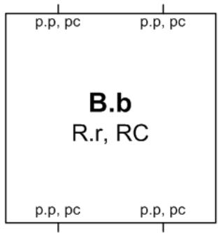
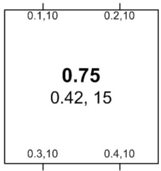
A template for and example of an STP Bridge. B.b is the Bridge Identifier (including the manageable priority component B.). R.r and RC are the Root Identifier, Root Path Cost, and the Designated Bridge Identifier, for the Root Port. p.p, pc are the Port Identifier (with manageable priority p.) and the Port Path Cost for a Bridge Port.
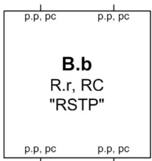
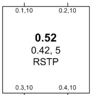
A template for and example of an RSTP Bridge.
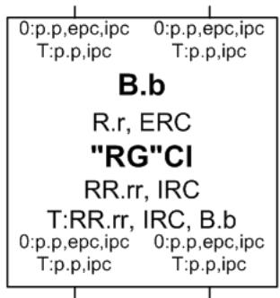
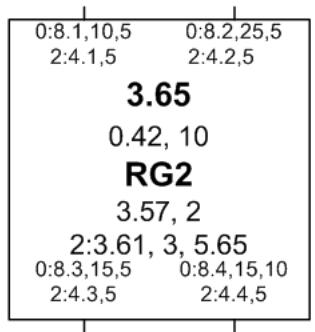
A template for and an example of an MSTP Bridge. B.b is the CIST Bridge Identifier. R.r, ERC, RR.rr are the CIST Root Identifier, External Root Path Cost, and Regional Root Identifier. CI identifies the Configuration Identifier for the Bridge. RR.rr, IRC the CIST Regional Root Identifier and the Internal Root Path Cost. T:RR.rr, IRC, B.b, is the Regional Root Identifier, Internal Root Path Cost IRC, and Bridge Identifier for the MSTI with MSTID T.
-p.p, epc, ipc are the CIST Port Identifier, External Port Path Cost, and Internal Port Path Cost for a Bridge Port. T:p.p, ipc are the Port Identifiers and their Regional Costs for MSTI T.
Any of the above information may be selectively omitted if deemed irrelevant for the purposes of a diagram.
A LAN
Connections between Bridges and LANs indicate the Port Role and Port State by means of their end point symbols, and in some examples, may show the transmission of BPDUs from a Port onto a LAN by means of arrowheads, as shown in the following table.
<table><tr><td>Port Role</td><td>Port State</td><td>Legend</td></tr><tr><td>Designated</td><td>DiscardingLearningForwarding</td><td>●||——●|——●——</td></tr><tr><td>& operEdge</td><td>Forwarding</td><td>●◇——</td></tr><tr><td>Root PortorMaster Port</td><td>DiscardingLearningForwarding</td><td>○||——○|——○——</td></tr><tr><td>Alternate</td><td>DiscardingLearningForwarding</td><td>—||——+———</td></tr><tr><td>Backup</td><td>DiscardingLearningForwarding</td><td>—|||——>——>——</td></tr><tr><td>Disabled</td><td>-</td><td><eq>\backslash</eq>——</td></tr><tr><td colspan="3">Transmitted Bpdus</td></tr><tr><td colspan="2">DesignatedDesignated ProposalRootRoot Agreement</td><td>——→——→——→——→——→</td></tr></table>
NOTE—These diagrammatic conventions allow the representation of Alternate and Backup Ports that are in Learning or Forwarding states; this can happen as a transitory condition due to implementation-dependent delays in switching off Learning and/or Forwarding on a Port that changes role from Designated or Root to Alternate or Backup.
Figure 13-1—Diagrammatic conventions
Figure 13-2 is an example Bridged Local Area Network, chosen to illustrate MSTP calculations rather than as an example of a common or desirable physical topology. Figure 13-3 is the same network showing Bridges and LANs with better CIST spanning tree priorities higher on the page, and including CIST priority vectors, port roles, and MST Regions. In this example:
a) Bridge 0.42 has been chosen as the CIST Root because it has the best (numerically the lowest) Bridge Identifier of all bridges in the network.
b) Bridges 0.57 and 2.83 are in the same MST Region (1) as 0.42, because they have the same MST Configuration Identifier as the latter. Because they are in the same MST Region as the CIST Root, their External Root Path Cost is 0, and their CIST Regional Root is the CIST Root.
c) LANs A, B, C, and D are in Region 1 because a Region 1 MST Bridge is the CIST Designated Bridge for those LANs, and there are no attached STP Bridges. LAN E is not in a Region (or is in a Region by itself, which is an equivalent view) because it is attached to Bridge 0.53, which is not an MST Bridge.
d) Bridges 0.77, 0.65, 0.97, 0.86, 3.84, and 3.72 are in the same MST Region (2) because they all have the same MST Configuration Identifier and are all interconnected by LANs for which one of them is the CIST Designated Bridge.
e) Bridge 0.86 is the CIST Regional Root for Region 2 because it is has the lowest External Root Path Cost through a Boundary Port.
f) LAN N is in Region 2 because its CIST Designated Bridge is in Region 2. Frames assigned to different MSTIDs may reach N from Bridge 0.86 (for example) by either Bridge 0.65 or Bridge 3.72, even though Bridges 0.94 and 0.69 with MST Configuration Identifiers that differ from those for the Bridges in Region 2 are attached to this shared LAN.
g) Bridges 0.94 and 0.69 are in different Regions, even though they have the same MST Configuration Identifier, because the LAN that connects them (N) is in a different Region.
Figure 13-4 shows a possible active topology of MSTI 2 within Region 2.
h) Bridge 0.65 has been chosen as the MSTI Regional Root because it has the best (numerically the lowest) Bridge Identifier of all bridges in the Region for this MSTI.
i) The connectivity between the whole of Region 2 and Region 1 is provided through a single Bridge Port, the Master Port on Bridge 0.86. This port was selected for this role because it is the CIST Root Port on the CIST Regional Root for the Region (see Figure 13-3).
j) The connectivity between the whole of Region 2 and LANs and Bridges outside the Region for the MSTI is the same as that for the CIST. This connectivity is similar to that which might result by replacing the entire Region by a single SST Bridge. The Region has a single Root Port (this port is the Master Port for each MSTI) and a number of Designated Ports.
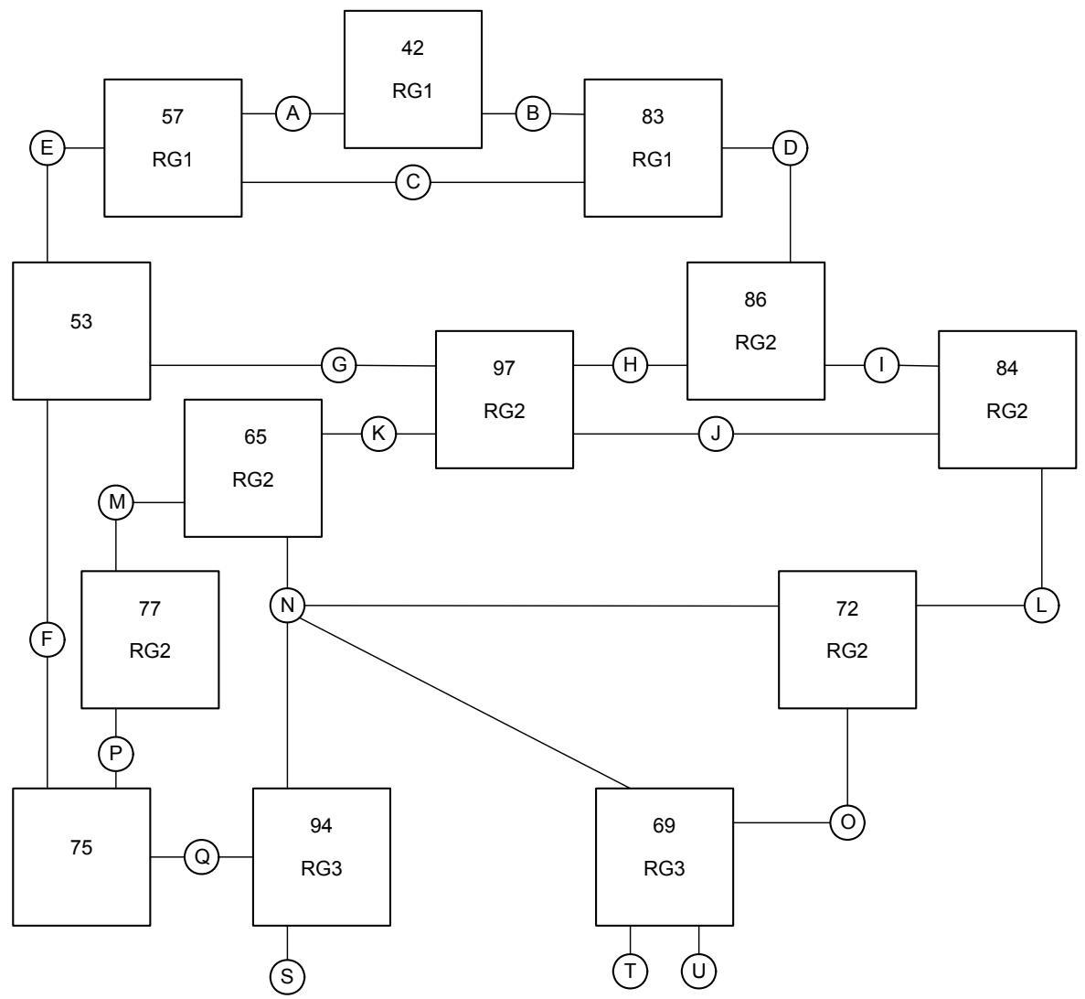
Figure 13-2—An example network
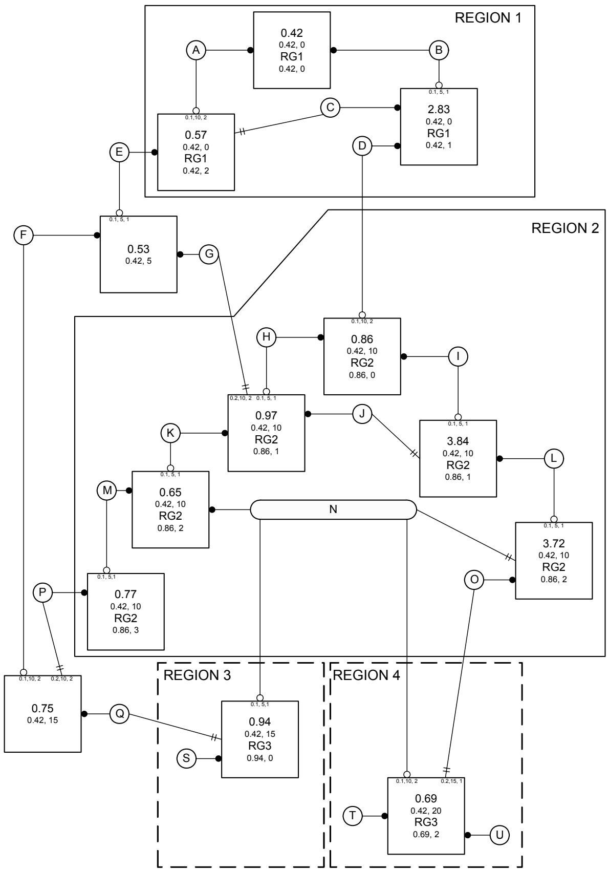
Figure 13-3—Example network with CIST Priority Vectors, Port Roles, and MST Regions
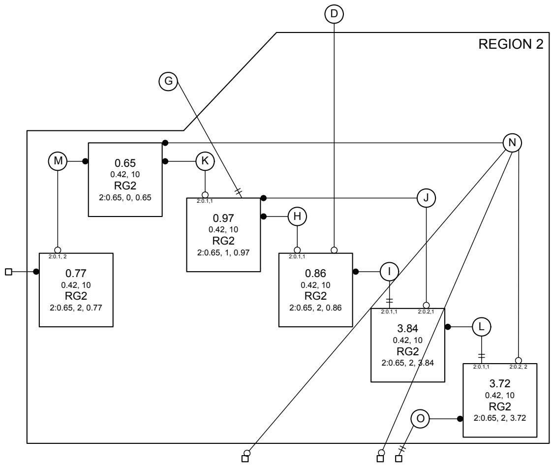
Connections to other MST regions
Figure 13-4—MSTI Active Topology in Region 2 of the example network
13.4 Relationship of MSTP to RSTP
The design of the Multiple Spanning Tree Protocol is based on that of the Rapid Spanning Tree Protocol (Clause 17 of IEEE Std 802.1D) extended to provide the capability for frames assigned to different VLANs to be transmitted along different paths within MST Regions.
a) The selection of the CIST Root Bridge and the computation of port roles for the CIST uses the same fundamental algorithm (17.3.1 of IEEE Std 802.1D) but extended priority vector components and calculations (13.9, 13.10) within MST Regions as compared with RSTP (17.5, 17.6 of IEEE Std 802.1D). The effect of these extensions is to cause each region to resemble a single bridge from the point of view of the CST as calculated by STP or RSTP.
b) MST Configuration Identification is specific to MSTP.
c) The selection of the MSTI Regional Root Bridge and computation of port roles for each MSTI also uses the same fundamental spanning tree algorithm but modified priority vector components (13.11).
d) Different Bridges may be selected as the Regional Root for different MSTIs by modifying the manageable priority component of the Bridge Identifier differently for the MSTIs.
e) The port roles used by the CIST (Root, Designated, Alternate, Backup or Disabled Port) are the same as those of STP and RSTP (17.3.1 of IEEE Std 802.1D). The MSTIs use the additional port
role Master Port. The Port States associated with each spanning tree and bridge port are the same as those of RSTP (7.4 of IEEE Std 802.1D).
f) The state variables associated with each port for each spanning tree and for the tree itself are those specified for RSTP as per bridge port and per bridge (17.15, 17.17, 17.18, 17.19 of IEEE Std 802.1D) with few exceptions, additions, and enhancements.
g) The state machine performance parameters specified for RSTP (17.13 of IEEE Std 802.1D) apply to the CIST, with a few exceptions, additions, and enhancements. A simplified set of performance parameters apply to the MSTIs.
h) The state machine procedures of RSTP are used (17.21 of IEEE Std 802.1D) with detailed changes.
MSTP, like RSTP:
i) Cannot protect against temporary loops caused by the interconnection of two LAN segments by devices other than Bridges (e.g., LAN repeaters) that operate invisibly with respect to support of the Bridges' MAC Internal Sublayer Service.
j) Provides for rapid recovery of connectivity following the failure of a Bridge, Bridge Port, or a LAN. The timers used define worst-case delays, only used to backup the normal operation of the protocol.
k) Provides a Force Protocol Version parameter, controlled by management and applicable to all Ports and trees supported by an MST bridge, to instruct MSTP to emulate aspects of early versions of spanning tree protocol. In particular, the Force Protocol Version parameter allows rapid transitions to be disabled. This reduces the risk of an increase, as compared with STP, in the rates of frame duplication and misordering in the network, as discussed in Annex K of IEEE Std 802.1D.
1) Allows Bridge Ports to be configured such that they can transition directly to the Forwarding Port State on re-initialization of the Bridge. This may be appropriate where a specific Bridge Port is known to be connected to a LAN segment that is not connected to further Bridges. The per port operational control, operEdge, that supports this behavior applies equally to all the spanning trees of an MST Bridge.
13.5 Modeling an MST Region as a single RSTP Bridge
The specification of MSTP is such that the nominal replacement of an entire MST Region by a single RSTP Bridge leads to little change in the behavior of the remainder of the Bridged Local Area Network. This design is intended to assist those familiar with the STP and RSTP specifications to comprehend and verify MSTP, and to administer Bridged Local Area Networks using the MSTP specification.
In a network comprising STP Bridges, RSTP Bridges, and multiple MST Regions, treating the MST Regions as single Bridges provides the network administrator with a natural hierarchy. The internal management of MST Regions can be largely separated from the management of the active topology of the bridge local area network as a whole.
The portion of the active topology of the network that connects any two bridges in the same MST Region traverses only MST Bridges and LANs in that region and never Bridges of any kind outside the region; in other words, connectivity within the region is independent of external connectivity. This is because the protocol parameters that determine the active topology of the network as a whole, the Root Identifier and Root Path Cost (known in the MSTP specification as the CIST Root Identifier and CIST External Root Path Cost) are carried unchanged throughout and across the MST Region, so bridges within the region will always prefer spanning tree information that has been propagated within the region to information that has exited the region and is attempting to re-enter it.
NOTE 1—No LAN can be in more than one Region at a time, so two Bridges (0.11 and 0.22 say) that would otherwise be in the same MST Region by virtue of having the same MST Configuration and of being directly connected by a LAN, may be in distinct regions if that is a shared LAN with other Bridges attached (having a different MST Configuration) and no other connectivity between 0.11 and 0.22 and lying wholly within their Region is available. The Region that the shared LAN belongs to may be dynamically determined. No such dynamic partitioning concerns arise with single Bridges. Obviously the sharing of LANs between administrative regions militates against the partitioning of concerns and should only be done following careful analysis.
The Port Path Cost (MSTP's External Port Path Cost) is added to the Root Path Cost just once at the Root Port of the CIST Regional Root, the closest Bridge in the Region to the Root Bridge of the entire network. The Message Age used by STP and RSTP is also only incremented at this Port. If the CIST Root is within an MST Region, it also acts as the Regional Root, and the Root Path Cost and Message Age advertised are zero, just as for a single Bridge.
Within an MST Region, each MSTI operates in much the same way as an independent instance of RSTP with dedicated Regional Root Identifier, Internal Root Path Cost, and Internal Port Path Cost parameters. Moreover, the overall spanning tree (the CIST) includes a fragment (the IST) within each MST Region that can be viewed as operating in the same way as an MSTI with the Regional Root as its root.
NOTE 2—Since an MST Region behaves like a single Bridge and does not partition (except in the unusual configuration involving shared LANs noted above), it has a single Root Port in the CST active topology. Partitioning a network into two or more Regions can therefore force non-optimal blocking of Bridge Ports at the boundaries rather than internal to those Regions.
13.6 STP and RSTP compatibility
MSTP is designed to be STP and RSTP compatible and interoperable without additional operational management practice.
13.6.1 Designated Port selection
Correct operation of the spanning tree protocols requires that all Bridge Ports attached to any given LAN agree on a single CIST Designated Port after a short interval sufficient for any Bridge Port to receive a configuration message from that Designated Port.
A unique spanning tree priority (13.9) is required for each Bridge Port for STP, which has no other way of communicating port roles. Since port numbers on different bridges are not guaranteed to be unique, this necessitates the inclusion of the transmitting Bridge's Bridge Identifier in the STP BPDU. RSTP and MSTP's Port Protocol Migration state machines (13.29) ensure that all Bridges attached to any LAN with an attached STP Bridge send and receive STP BPDUs exclusively.
NOTE 1—This behavior satisfies the requirement for unique, agreed Designated Port for LANs with attached STP Bridges, but means that an MST Region cannot completely emulate a single Bridge since the transmitted Designated Bridge Identifier can differ on Bridge Ports at the Region’s boundary.
MSTP transmits and receives the Regional Root Identifier and not the Designated Bridge Identifier in the BPDU fields recognized by RSTP (14.6) to allow both the MSTP and the RSTP Bridges potentially connected to a single LAN to perform comparisons (13.9, 13.10) between all spanning tree priority vectors transmitted that yield a single conclusion as to which RSTP Bridge or MST Region includes the Designated Port. MST and RST BPDUs convey the transmitting port's CIST Port Role. This is checked on receipt by RSTP when receiving messages from a Designated Bridge (17.21.8 of IEEE Std 802.1D), thus ensuring that an RSTP Bridge does not incorrectly identify one MST Bridge Port as being Designated rather than another, even while omitting the competing Bridge Ports' Designated Bridge Identifiers from comparisons.
NOTE 2—This ability of MSTP Bridges to communicate the full set of MSTP information on shared LANs to which RSTP Bridges are attached avoids the need for the Port Protocol Migration machines to detect RSTP Bridges. Two or more MSTP and one or more RSTP Bridges may be connected to a shared LAN, with full MSTP operation. This includes the possibility of different MSTI Designated Ports (see 13.3.1).
13.6.2 Force Protocol Version
A Force Protocol Version parameter, controlled by management, instructs MSTP to emulate additional aspects of the behavior of earlier versions of spanning tree protocol that are not strictly required for interoperability. The value of this parameter applies to all Ports of the Bridge.
a) ST BPDUs, rather than MST BPDUs, are transmitted if Force Protocol Version is 0. RST BPDUs omit the MST Configuration Identifier and all MSTI Information.
b) RST BPDUs, rather than MST BPDUs, are transmitted if Force Protocol Version is 2. RST BPDUs omit the MST Configuration Identifier and all MSTI Information.
c) All received BPDUs are treated as being from a different MST Region if Force Protocol Version is 0 or 2.
d) The MSTP state machines disable rapid transitions if Force Protocol Version is 0. This allows MSTP Bridges to support applications and protocols that may be sensitive to the increased rates of frame duplication and misordering that can arise under some circumstances, as discussed in Annex K of IEEE Std 802.1D.
e) The MSTP state machines allow full MSTP behavior if Force Protocol Version is 3 or more.
NOTE 1—Allowing for the case of a Force Protocol Version parameter value greater than 3 can simplify management of Bridges with different protocol versions.
NOTE 2—The Force Protocol Version parameter does not support multiple spanning trees with rapid transitions disabled.
13.7 MST Configuration Identification
It is essential that all Bridges within an MST Region agree on the allocation of VIDs to specific spanning trees. If the allocation differs, frames for some VIDs may be duplicated or not delivered to some LANs at all. MST Bridges check that they are allocating VIDs to the same spanning trees as their neighboring MST Bridges in the same Region by transmitting and receiving MST Configuration Identifiers along with the spanning tree information. These MST Configuration Identifiers, while compact, are designed so that two matching identifiers have a very high probability of denoting the same configuration even in the absence of any supporting management practice for identifier allocation.
NOTE 1—Suitable management practices for the deployment of equipment and the choice of Configuration Names and Revision Levels (see below) can be used to guarantee that the MST Configuration Identifiers will differ if the VID to spanning tree allocation differs within a single administrative domain.
Each MST Configuration Identifier contains the following components:
1) A Configuration Identifier Format Selector, the value 0 encoded in a fixed field of one octet to indicate the use of the following components as specified in this standard.
2) The Configuration Name, a variable length text string encoded within a fixed field of 32 octets, conforming to RFC 2271's definition of SnmpAdminString. If the Configuration Name is less than 32 characters in length, the corresponding text string should be terminated by the NUL character, with the remainder of the 32-octet field filled with NUL characters. Otherwise, if the Configuration Name is exactly 32 characters in length, the corresponding text string is encoded with no terminating NUL character.
3) The Revision Level, an unsigned integer encoded within a fixed field of 2 octets.
4) The Configuration Digest, a 16-octet signature of type HMAC-MD5 (see IETF RFC 2104) created from the MST Configuration Table (3.17, 8.9). For the purposes of calculating the Configuration Digest, the MST Configuration Table is considered to contain 4096 consecutive two octet elements, where each element of the table (with the exception of the first and last) contains an MSTID value encoded as a binary number, with the first octet being most significant. The first element of the table contains the value 0, the second element the MSTID value corresponding to VID 1, the third element the MSTID value corresponding to VID 2, and so on, with the next to last element of the table containing the MSTID value corresponding to VID 4094, and the last element containing the value 0. The key used to generate the signature consists of the 16-octet string specified in Table 13-1.
Table 13-1—Configuration Digest Signature Key
<table><tr><td>Parameter</td><td>Mandatory value</td></tr><tr><td>Configuration Digest Signature Key</td><td>0x13AC06A62E47FD51F95D2BA243CD0346</td></tr></table>
NOTE 2—The formulation of the signature as described above does not imply that a separate VID to MSTID translation table has to be maintained by the implementation; rather that it should be possible for the implementation to derive the logical contents of such a table, and the signature value as specified above, from the other configuration information maintained by the implementation, as described in Clause 12.
The Configuration Digests of some VID to MSTID translations are shown in Table 13-2 to help verify implementations of this specification.
Table 13-2—Sample Configuration Digest Signature Keys
<table><tr><td>VID to MSTID translation</td><td>Configuration Digest</td></tr><tr><td>All VIDs map to the CIST, no VID mapped to any MSTI</td><td>0xAC36177F50283CD4B83821D8AB26DE62</td></tr><tr><td>All VIDs map to MSTID 1</td><td>0xE13A80F11ED0856ACD4EE3476941C73B</td></tr><tr><td>Every VID maps to the MSTID equal to (VID modulo 32) + 1</td><td>0x9D145C267DBE9FB5D893441BE3BA08CE</td></tr></table>
It is recommended that MST Bridge implementations provide an easily selectable or default configuration comprising a Configuration Name of the Bridge Address as a text string using the Hexadecimal Representation specified in IEEE Std 802, a Revision Level of 0, and a Configuration Digest representing a VID to MSTID translation table containing the value 0 for every element. Such a table represents the mapping of all VLANs to the CIST. Since the Bridge Address is unique to each MST Bridge, no two MST Bridges using this default configuration will be identified as belonging to the same MST Region.
13.8 MST Regions
An MST Region comprises one or more MST Bridges with the same MST Configuration Identifiers, using the same MSTIs, interconnected by and including LANs for which one of those Bridges is the Designated Bridge for the CIST and which have no Bridges attached that cannot receive and transmit RST BPDUs.
13.9 Spanning Tree Priority Vectors
All Bridges, whether they use STP, RSTP, or MSTP, send information to each other, in Configuration Messages (13.14 of this standard, 17.8 of IEEE Std 802.1D) to assign Port roles that determine each Port's participation in a fully and simply connected active topology based on one or more spanning trees. The information communicated is known as a spanning tree priority vector. Spanning tree priority vectors provide the basis for a concise specification of each protocol's computation of the active topology, in terms of both the entire network and the operation of individual Bridges in support of the distributed algorithm.
CIST priority vectors comprise the following components:
a) CIST Root Identifier, the Bridge Identifier of the CIST Root;
b) CIST External Root Path Cost, the path cost between MST Regions from the transmitting Bridge to the CIST Root;
c) CIST Regional Root Identifier, the Bridge Identifier of the single bridge in a Region whose CIST Root Port is a Boundary Port, or the Bridge Identifier of the CIST Root if that is within the Region;
d) CIST Internal Root Path Cost, the path cost to the CIST Regional Root;
e) CIST Designated Bridge Identifier, the Bridge Identifier for the transmitting bridge for the CIST;
f) CIST Designated Port Identifier, the Port Identifier for the transmitting port for the CIST;
g) CIST Receiving Port Identifier (not conveyed in Configuration Messages, used as tie-breaker between otherwise equal priority vectors within a receiving Bridge).
The CIST External Root Path Cost is significant throughout the network. It is propagated along each path from the CIST Root, and is added to at Bridge Ports that receive the priority vector from a Bridge in a different MST Region. The External Path Cost transmitted by a Bridge thus represents costs accumulated at the Root Ports of Bridges that are either not MST Bridges or are CIST Regional Roots and is constant within a Region. The CIST Internal Root Path Cost is only significant and explicitly defined within a Region.
NOTE 1—The path to the CIST Root from a bridge with a CIST Root Port within a region always goes to or through the CIST Regional Root.
NOTE 2—The STP and RSTP specifications refer to the CIST Root Identifier and CIST External Root Path Cost simply as the Root Bridge Identifier and Root Path Cost, respectively, and omit the CIST Internal Root Path Cost. MSTP encodes the CIST Regional Root Identifier in the (External Designated) Bridge Identifier BPDU field used by RSTP to convey the Designated Bridge Identifier (14.3.3), so an entire MST Region appears to an RSTP capable Bridge as a single Bridge. However, this is not possible for STP, as the latter lacks the fields necessary for MST Bridges to communicate the Designated Bridge Identifier to resolve a potential priority vector tie, and MSTP BPDUs are not sent on a LAN to which an STP Bridge is attached.
MSTI priority vectors comprise the following components:
h) MSTI Regional Root Identifier, the Bridge Identifier of the MSTI Regional Root for this particular MSTI in this MST Region;
i) MSTI Internal Root Path Cost, the path cost to the MSTI Regional Root for this particular MSTI in this MST Region;
j) MSTI Designated Bridge Identifier, the Bridge Identifier for the transmitting bridge for this MSTI;
k) MSTI Designated Port Identifier, the Port Identifier for the transmitting port for this MSTI;
1) MSTI Receiving Port Identifier (not conveyed in Configuration Messages).
The set of priority vectors for a given MSTI is only defined within an MST Region. Within each Region they are totally and uniquely ordered. A CIST Root Identifier, CIST External Root Path Cost, and CIST Regional Root Identifier tuple defines the connection of the Region to the external CST and is required to be associated with the source of the MSTI priority vector information when assessing the agreement of information for rapid transitions to forwarding, but plays no part in priority vector calculations.
As each Bridge and Bridge Port receives priority vector information from other Bridges and Ports closer to the Root, priority vector calculations and comparisons are made to decide which priority information to record, and what information to be passed on. Decisions about a given Port's role are made by comparing the priority vector components that could be transmitted with that received by the Port. For all components, a lesser numerical value is better, and earlier components in the above lists are more significant. As each Bridge Port receives priority vector information from Ports closer to the Root, additions are made to one or more priority vector components to yield a worse priority vector for potential transmission through other ports of the same Bridge.
NOTE 3—The consistent use of lower numerical values to indicate better information is deliberate as the Designated Port that is closest to the Root Bridge, i.e., has a numerically lowest path cost component, is selected from among potential alternatives for any given LAN (13.9). Adopting the conventions that lower numerical values indicate better information, that where possible more significant priority components are encoded earlier in the octet sequence of a BPDU (14.3), and that earlier octets in the encoding of individual components are more significant (14.2) allow concatenated octets that compose a priority vector to be compared as if they were a multiple octet encoding of a single number, without regard to the boundaries between the encoded components. To reduce the confusion that naturally arises from having the lesser of two numerical values represent the better of the two, i.e., the one to be chosen all other factors being equal, this clause uses the following consistent terminology. Relative numeric values are described as “least,” “lesser,” “equal,” and “greater,” and their comparisons as “less than,” “equal to,” or “greater than,” while relative Spanning Tree priorities are described as “best,” “better,” “the same,” “different,” and “worse” and their comparisons as “better than,” “the same as,” “different from,” and “worse than.” The operators “<” and “=” represent less than and equal to, respectively. The terms “superior” and “inferior” are used for comparisons that are not simply based on priority but include the fact that a priority vector can replace an earlier vector transmitted by the same Bridge Port. All of these terms are defined for priority vectors in terms of the numeric comparison of components below (13.10, 13.11).
NOTE 4—To ensure that the CIST and each MSTI's view of the boundaries of each MST region remain in synchronization at all times, each BPDU carries priority vector information for the CIST as well as for MSTIs. Associating the CIST Root Identifier, External Path Cost, and Regional Root Identifier with the priority vector information for each MSTI does not therefore raise a requirement to transmit these components separately. A single bit per MSTI vector, the Agreement flag, satisfies the requirement to indicate that the vector beginning with the MSTI Regional Root Identifier for that specific MSTI has always been associated with the single CIST Root Identifier, etc. transmitted in the BPDU.
To allow the active topology to be managed for each tree through adjusting the relative priority of different Bridges and Bridge Ports for selection as the CIST Root, a CIST or MSTI Regional Root, Designated Bridge, or Designated Port, the priority component of the Bridge's Bridge Identifier can be independently chosen for the CIST and for each MSTI. The priority component used by the CIST for its CIST Regional Root Identifier can also be chosen independently of that used for the CIST Root Identifier. Independent configuration of Port Path Cost and Port Priority values for the CIST and for each MSTI can also be used to control selection of the various roles for the CIST and for each MSTI.
13.10 CIST Priority Vector calculations
The port priority vector is the priority vector held for the port when the reception of BPDUs and any pending update of information has been completed:
  port priority vector = {RootID : ExtRootPathCost :
  RRootID : IntRootPathCost :
  DesignatedBridgeID : DesignatedPortID : RcvPortID}
The message priority vector is the priority vector conveyed in a received Configuration Message. For a Bridge with Bridge Identifier B receiving a Configuration Message on a Port $P_{B}$ from a Designated Port $P_{D}$ on Bridge D claiming a CIST Root Identifier of $R_{D}$ , a CIST External Root Path Cost of $ERC_{D}$ , a CIST Regional Root Identifier of $RR_{D}$ , and a CIST Internal Root Path Cost of $IRC_{D}$ :
message priority vector = $\{R_{D}:ERC_{D}:RR_{D}:IRC_{D}:D:P_{D}:P_{B}\}$
If $B$ is not in the same MST Region as $D$ , the Internal Root Path Cost is decoded as 0, as it has no meaning to $B$ .
NOTE—If a Configuration Message is received in an RST or ST BPDU, both the Regional Root Identifier and the Designated Bridge Identifier are decoded from the single BPDU field used for the Designated Bridge Parameter (the MST BPDU field in this position encodes the CIST Regional Root Identifier). An STP or RSTP Bridge is always treated by MSTP as being in an MST Region of its own, so the Internal Root Path Cost is decoded as zero, and the tests below become the familiar checks used by STP and RSTP.
The received CIST message priority vector is the same as B's port priority vector if:
$$
\left(R _ {D} = = R o o t I D\right) \& \& \left(E R C _ {D} = = E x t R o o t P a t h C o s t\right) \& \& \left(R R _ {D} = = R R o o t I D\right) \& \&
$$
$$
\left(I R C _ {D} = = I n t R o o t P a t h C o s t\right) \& \& (D = = D e s i g n a t e d B r i d g e I D) \& \& \left(P _ {D} = = D e s i g n a t e d P o r t I D\right)
$$
and is better if:
$$
\begin{array}{l} \left(\left(R _ {D} < \text { RootID }\right)\right) \mid \mid \\ \left(\left(R _ {D} = = \text { RootID }\right) \& \& \left(E R C _ {D} < \text { ExtRootPathCost }\right)\right) \mid \mid \\ \left(\left(R _ {D} = = \text {RootID}\right) \& \& \left(E R C _ {D} = = \text {ExtRootPathCost}\right) \& \& \left(R R _ {D} < R \text {RootID}\right)\right) \| \\ \left(\left(R _ {D} = = R o o t I D\right) \& \& \left(E R C _ {D} = = E x t R o o t P a t h C o s t\right) \& \& \left(R R _ {D} = = R R o o t I D\right) \right. \\ \& \& (I R C _ {D} < I n t R o o t P a t h C o s t)) | | \\ \left(\left(R _ {D} = = \text {RootID}\right) \& \& \left(E R C _ {D} = = \text {ExtRootPathCost}\right) \& \& \left(R R _ {D} = = R \text {RootID}\right) \right. \\ \& \& (I R C _ {D} = = I n t R o o t P a t h C o s t) \& \& (D < D e s i g n a t e d B r i d g e I D)) | | \\ \left(\left(R _ {D} = = R o o t I D\right) \& \& \left(E R C _ {D} = = E x t R o o t P a t h C o s t\right) \& \& \left(R R _ {D} = = R R o o t I D\right) \right. \\ \& \& (I R C _ {D} = = I n t R o o t P a t h C o s t) \& \& (D = = D e s i g n a t e d B r i d g e I D) \\ \& \& (P _ {D} < D e s i g n a t e d P o r t I D)) \\ \end{array}
$$
A received CIST message priority vector is superior to the port priority vector if, and only if, the message priority vector is better than the port priority vector, or the Designated Bridge Identifier Bridge Address and Designated Port Identifier Port Number components are the same; in which case, the message has been transmitted from the same Designated Port as a previously received superior message, i.e., if:
$$
\begin{array}{l} \left(\left\{R _ {D}: E R C _ {D}: R R _ {D}: I R C _ {D}: D: P _ {D}: P _ {B} \right\} \right. \\ i s b e t t e r t h a n \\ \{R o o t I D: E x t R o o t P a t h C o s t: R R o o t I D: I n t R o o t P a t h C o s t: \\ \text { DesignatedBridgeID }: \text { DesignatedPortID }: R c v P o r t I D \} \\ ) | | ((D. B r i d g e A d d r e s s = = D e s i g n a t e d B r i d g e I D. B r i d g e A d d r e s s) \& \& \\ (P _ {D}. \text { PortNumber } = = \text { DesignatedPortID }. \text { PortNumber })) \\ \end{array}
$$
If the message priority vector received in a Configuration Message from a Designated Port is superior, it will replace the current port priority vector.
A root path priority vector for a Port can be calculated from a port priority vector that contains information from a message priority vector, as follows.
If the port priority vector was received from a bridge in a different MST Region (13.26.4), the External Port Path Cost $EPC_{PB}$ is added to the External Root Path Cost component, and the Regional Root Identifier is set to the value of the Bridge Identifier for the receiving Bridge. The Internal Root Path Cost component will have been set to zero on reception.
$$
\text { root path priority vector } = \{R _ {D}: E R C _ {D} + E P C _ {P B}: B: 0: D: P _ {D}: P _ {B})
$$
If the port priority vector was received from a bridge in the same MST Region (13.26.4), the Internal Port Path Cost $IPC_{PB}$ is added to the Internal Root Path Cost component.
$$
\text { root path priority vector } = \{R _ {D}: E R C _ {D}: R R _ {D}: I R C _ {D} + I P C _ {P B}: D: P _ {D}: P _ {B})
$$
The bridge priority vector for a Bridge B is the priority vector that would, with the Designated Port Identifier set equal to the transmitting Port Identifier, be used as the message priority vector in Configuration Messages transmitted on Bridge B's Designated Ports if B was selected as the Root Bridge of the CIST.
$$
\text { bridge priority vector } = \{B: 0: B: 0: B: 0: 0 \}
$$
The root priority vector for Bridge B is the best priority vector of the set of priority vectors comprising the bridge priority vector plus all root path priority vectors whose Designated Bridge Identifier D is not equal to B. If the bridge priority vector is the best of this set of priority vectors, Bridge B has been selected as the Root of the tree.
The designated priority vector for a port Q on Bridge B is the root priority vector with B's Bridge Identifier B substituted for the DesignatedBridgeID and Q's Port Identifier $Q_{B}$ substituted for the DesignatedPortID and RcvPortID components. If Q is attached to a LAN that has one or more STP Bridges attached (as determined by the Port Protocol Migration state machine), B's Bridge Identifier B is also substituted for the RRootID component.
If the designated priority vector is better than the port priority vector, the Port will be the Designated Port for the attached LAN and the current port priority vector will be updated. The message priority vector in Configuration Messages transmitted by a Port always comprises the components of the designated priority vector of the Port, even if the Port is a Root Port.
13.11 MST Priority Vector calculations
The port priority vector is the priority vector held for the port when the reception of BPDUs and any pending update of information has been completed:
$$
\text { port priority vector } = \quad \begin{array}{l} \{\text { RRootID }: \text { IntRootPathCost }: \\ \text { DesignatedBridgeID }: \text { DesignatedPortID }: \text { RcvPortID } \} \end{array}
$$
The message priority vector is the priority vector conveyed in a received Configuration Message. For a Bridge with Bridge Identifier B receiving a Configuration Message on a Regional Port $P_{B}$ from a Designated Port $P_{D}$ on Bridge D belonging to the same MST Region and claiming an Internal Root Path Cost of $IRC_{D}$ :
$$
m e s s a g e p r i o r i t y v e c t o r = \{R R _ {D}: I R C _ {D}: D: P _ {D}: P _ {B} \}
$$
An MSTI message priority vector received from a Bridge that does not belong to the same MST Region is discarded.
An MSTI message priority vector received from a bridge port internal to the region is the same as the port priority vector if:
$$
\begin{array}{r l} & ((R R _ {D} = = R R o o t I D) \& \& (I R C _ {D} = = I n t R o o t P a t h C o s t) \& \& (D = = D e s i g n a t e d B r i d g e I D) \\ & \quad \& \& (P _ {D} = = D e s i g n a t e d P o r t I D)) \end{array}
$$
and is better if:
$$
\begin{array}{l} \left(\left(R R _ {D} < R R o o t I D\right)\right) \mid \mid \\ \left(\left(R R _ {D} = = R \text {RootID}\right) \& \& \left(I R C _ {D} < I n t R o o t P a t h C o s t\right)\right) \mid \\ \left(\left(R R _ {D} = = R R o o t I D\right) \& \& \left(I R C _ {D} = = I n t R o o t P a t h C o s t\right) \& \& (D < D e s i g n a t e d B r i d g e I D)\right) \| \\ \end{array}
$$
$$
\begin{array}{r l} \left(\left(R R _ {D} = = R R o o t I D\right) \& \& \left(I R C _ {D} = = I n t R o o t P a t h C o s t\right) \& \& (D = = D e s i g n a t e d B r i d g e I D) \right. \\ & \& \& \left(P _ {D} < D e s i g n a t e d P o r t I D)\right) \end{array}
$$
An MSTI message priority vector is superior to the port priority vector if, and only if, the message priority vector is better than the port priority vector, or the Designated Bridge Identifier Bridge Address and Designated Port Identifier Port Number components are the same; in which case, the message has been transmitted from the same Designated Port as a previously received superior message, i.e., if:
$$
\begin{array}{l} \left(\left\{R R _ {D}: I R C _ {D}: D: P _ {D}: P _ {B} \right\} \right. \\ \text {is better than} \\ \left\{\text {RRootID : IntRootPathCost : DesignatedBridgeID : DesignatedPortID : RcvPortID} \right\} \\ \mid \mid ((D. B r i d g e A d d r e s s = = D e s i g n a t e d B r i d g e I D. B r i d g e A d d r e s s) \& \& \\ \left(P _ {D}. P o r t N u m b e r = = D e s i g n a t e d P o r t I D. P o r t N u m b e r)\right) \end{array}
$$
If the message priority vector received in a Configuration Message from a Designated Port for the MSTI is superior, it will replace the current port priority vector.
NOTE 1—The agree flag (13.24.1) for the Port and this MSTI will be cleared if the CIST Root Identifier, CIST External Root Path Cost, and CIST Regional Root Identifier in the received BPDU are not better than or the same as those for the CIST designated priority vector for the port following processing of the received BPDU.
A root path priority vector for a given MSTI can be calculated for a Port that has received a port priority vector from a bridge in the same region by adding the Internal Port Path Cost $IPC_{PB}$ to the Internal Root Path Cost component.
$$
\text { root path priority vector } = \{R R _ {D}: I R C _ {D} + I P C _ {P B}: D: P _ {D}: P _ {B} \}
$$
NOTE 2—Internal Port Path Costs are independently manageable for each MSTI, as are the priority components of the Bridge and Port Identifiers. This permits topology management of each MSTI independent of other MSTIs. The ability to independently manage MSTIs in this way without explicitly transmitting individual Port Path Costs is a key reason for retaining the use of a Distance Vector protocol for constructing MSTIs. A simple Link State Protocol requires transmission (or a priori sharing) of all Port Costs for all links.
The bridge priority vector for a Bridge B is the priority vector that would, with the Designated Port Identifier set equal to the transmitting Port Identifier, be used as the message priority vector in Configuration Messages transmitted on Bridge B's Designated Ports if B was selected as the Root Bridge of a given tree.
$$
b r i d g e \quad p r i o r i t y \quad v e c t o r = \{B: 0: B: 0 \}
$$
The root priority vector for Bridge $B$ is the best priority vector of the set of priority vectors comprising the bridge priority vector plus all root path priority vectors whose Designated Bridge Identifier $D$ is not equal to $B$ . If the bridge priority vector is the best of this set of priority vectors, Bridge $B$ has been selected as the Root of the tree.
The designated priority vector for a port Q on Bridge B is the root priority vector with B's Bridge Identifier B substituted for the DesignatedBridgeID and Q's Port Identifier $Q_{B}$ substituted for the DesignatedPortID and RcvPortID components.
If the designated priority vector is better than the port priority vector, the Port will be the Designated Port for the attached LAN and the current port priority vector will be updated. The message priority vector in MSTP BPDUs transmitted by a Port always comprises the components of the designated priority vector of the Port, even if the Port is a Root Port.
Figure 13-4 shows the priority vectors and the active topology calculated for an MSTI in a Region of the example network of Figure 13-3.
13.12 Port Role assignments
Port Role assignments for Bridge Ports that are enabled are determined by each bridge in the Bridged Local Area Network (13.12) according to the source and relative priority of the spanning tree port priority vectors (13.9) selected for each Port following priority vector calculations (13.10, 13.11).
Each MST Bridge Port that is enabled is assigned a Port Role for each spanning tree. First one of the following roles: Root Port, Designated Port, Alternate Port, or Backup Port, is assigned for the CIST.
a) If the Bridge is not the CIST Root, the Port that is the source of the root priority vector is the CIST Root Port.
b) Each Port whose port priority vector is the designated priority vector derived from the root priority vector is a CIST Designated Port.
c) Each Port, other than the Root Port, that has a port priority vector that has been received from another Bridge is a CIST Alternate Port.
d) Each Port that has a port priority vector that has been received from another Port on this Bridge is a CIST Backup Port.
Then one of these roles, or the additional role of Master Port, is assigned for each MSTI.
e) If the Port is the CIST Root Port and the CIST port priority vector was received from a Bridge in another MST Region, the Port is the MSTI Master Port.
f) If the Bridge is not the MSTI Regional Root, the Port that is the source of the MSTI root priority vector is the MSTI Root Port.
g) Each Port whose port priority vector is the designated priority vector derived from the root priority vector is a MSTI Designated Port.
h) Each Port, other than a Master Port or Root Port, that has a port priority vector that has been received from another Bridge or has a CIST port priority vector that has been received from a Bridge in a different region, is an MSTI Alternate Port.
i) Each Port that has a port priority vector that has been received from another Port on this Bridge is an MSTI Backup Port.
If the Port is not enabled, it is assigned the Disabled Port role for the CIST and all MSTIs, to identify it as having no part in the operation of any of the spanning trees or the active topology of the network. The Disabled Port role is assigned if the port is not operational or is excluded from the active topology by management, i.e., its MAC_Operational status (6.4.2) is FALSE, or it is a network access port (IEEE Std 802.1X) and its AuthControlledPortStatus is Unauthorized, or its Administrative Bridge Port state is Disabled (14.8.2.2 of Std 802.1D).
13.13 Stable connectivity
This subclause provides an analysis to show that MSTP meets its goal of providing full and simple connectivity for frames allocated to any given VLAN in a stable network, i.e., where the physical topology has remained constant for long enough that the spanning tree information communicated and processed by Bridges is not changing on any Bridge Port.
Each MST Region independently can allocate such frames to the IST or any given MSTI. Root Ports, Designated Ports, and Master Ports forward data frames, and Alternate, Backup, and Disabled Ports do not.
NOTE—The term “Common Spanning Tree (CST)” refers to the CIST connectivity between Regions, and the term “Internal Spanning Tree (IST)” to the CIST connectivity within each Region.
The CIST interconnects both individual LANs and Bridges and complete MST Regions into a single spanning tree, each Region being part of the CIST as a whole. Frames with VIDs consistently allocated to the CIST within every MST Region follow an active topology determined by the minimum path costs to each Bridge and LAN provided by that single tree throughout the network and thus enjoy full and simple connectivity.
Frames otherwise allocated follow the CIST outside and an MSTI within an MST Region. Simple and, in the absence of continual changes in physical connectivity, full connectivity of this composite active topology is ensured as follows:
a) Each Bridge or LAN is in one and only one Region. (SST Bridges, LANs connected to STP Bridges, and LANs whose Designated Bridge is an SST Bridge, are all conveniently regarded as being in a Region of their own.)
b) Each and every frame is associated with one and only one VID.
c) Frames with any given VID are allocated either to the IST or to a given MSTI within any given Region, i.e., all frames are allocated to some tree and no frames are allocated to more than one tree.
d) The IST and each MSTI provides full and simple connectivity between all LANs and Bridges in an MST Region for frames allocated to the IST or that MSTI.
Hence, full and simple connectivity is provided for all frames from any Bridge or LAN within an MST Region to any other within the Region.
Furthermore:
e) All Bridges within an MST Region with ports connected to a given LAN reach a consistent agreement as to whether each of those ports is or is not a Boundary Port (i.e., attaches a Bridge to a LAN that is not in the same Region) prior to forwarding frames. (MST Bridges make the determination on the basis of the CIST Designated Port for the LAN or the selection of the protocol by the Protocol Migration machines, both are necessarily complete prior to frame forwarding. SST Bridges being unaware of MST Regions behave as if each LAN is in a different Region to the Bridge.)
f) At a Boundary Port frames allocated to the CIST and all MSTIs are forwarded or not forwarded alike. This is because Port Role assignments are such that if the CIST Port Role is Root Port, the MSTI Port Role will be Master Port, and if the CIST Port Role is Designated Port, Alternate Port, Backup Port, or Disabled Port, each MSTI's Port Role will be the same.
g) The CIST provides full and simple connectivity between all LANs and Bridges in the network, including the LANs and Bridges attached to the Boundary Ports of any MST Region.
Hence, full and simple connectivity is provided for all frames between Bridges and LANs outside the MST Region since those frames will be carried across the MST Region if necessary, just as if they were allocated to the CIST whichever tree they are allocated to within the Region.
Similarly full and simple connectivity is provided for all frames between a Bridge or LAN inside the Region and a Bridge or LAN outside the region since the connectivity provided from within the Region by an MSTI to that outer Bridge or LAN is the same as that provided by the CIST.
Figure 13-5 illustrates the above connectivity with the simple example of Region 1 from the example network of Figure 13-3 and Figure 13-4. Bridge 0.42 has been selected as the CIST Root and Regional Root, Bridge 0.57 as the Regional Root for MSTI 1, and Bridge 2.83 for MSTI 2 by management of the per MSTI Bridge Identifier priority component. The potential loop through the three bridges in the Region is blocked at different Bridge Ports for the CIST, and each MSTI, but the connectivity across the Region and from each LAN and Bridge in the region through the boundaries of the Region is the same in all cases.
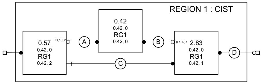
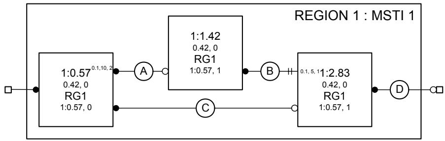
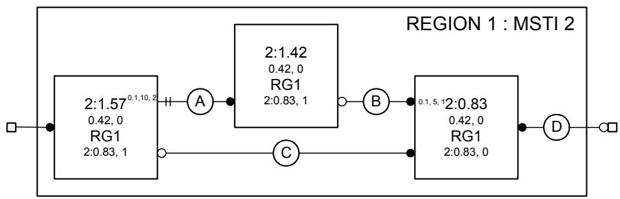
Figure 13-5—CIST and MSTI active topologies in Region 1 of the example network
13.14 Communicating Spanning Tree information
Bridges transmit and receive MAC frames, each containing a Bridge Protocol Data Unit (BPDU) (Clause 9 and Clause 14 of IEEE Std 802.1D), to communicate Spanning Tree messages. A MAC frame conveying a BPDU carries the Bridge Group Address in the destination address field and is received by all the Bridges connected to the LAN on which the frame is transmitted. The Bridge Group Address is one of a small number of addresses that identify frames that are not directly forwarded by Bridges (8.6.3), but the information contained in the BPDU can be used by a Bridge in calculating its own BPDUs to transmit and can stimulate that transmission.
BPDUs are used to convey three types of Spanning Tree messages:
a) Configuration Messages;
b) Topology Change Notification (TCN) Messages;
c) MST Configuration Identifiers.
A Configuration Message for the CIST can be encoded and transmitted in an STP Configuration BPDU (14.3.1), an RST BPDU (14.3.2), or an MST BPDU (14.3.3). A TCN Message for the CIST can be encoded in an STP Topology Change Notification BPDU (14.3.1), an RST BPDU with the TC flag set, or an MST BPDU. Configuration and TCN Messages for the CIST and for all MSTIs in an MST Region are encoded in a single MST BPDU, as is the MST Configuration Identifier. No more than 64 MSTI Configuration Messages shall be encoded in an MST BPDU, and no more than 64 MSTIs shall be supported by an MST Bridge.
Configuration and Topology Change Notification BPDUs are distinguished from each other and from RST and MST BPDUs by their BPDU Type (Clause 9 of IEEE Std 802.1D). RST and MST BPDUs share the same BPDU Type and are distinguished by their version identifiers. Bridges implementing STP (Clause 8 of IEEE Std 802.1D, 1998 Edition) transmit and decode Configuration and Topology Change Notification BPDUs, and ignore RST and MST BPDUs on receipt. This ensures that connection of a Bridge Port of such a Bridge to a LAN that is also attached to by a Bridge implementing RSTP or MSTP is detected, as transmission of RSTP or MSTP BPDUs does not suppress regular transmissions by the STP Bridge. This functionality is provided by the Port Protocol Migration state machine for RSTP (17.24 of IEEE Std 802.1D) and MSTP (13.29). The Port Protocol Migration state machines select the BPDU types used to encode Spanning Tree messages so that all Bridges attached to the same LAN participate in a spanning tree protocol, while maximizing the available functionality. If one or more attached Bridges only implement STP, only Configuration and Topology Change Notification BPDUs will be used and the functionality provided by the protocol will be constrained.
Each Configuration Message contains, among other parameters, a message priority vector (13.9). This allows a receiving Bridge to determine the Port Role (13.12), including that of Designated Port. Configuration Messages are transmitted if the information to be transmitted by a Designated Port changes, or if a Root, Master, Alternate, or Backup Port has an Agreement to convey. In addition, Designated Ports transmit Configuration Messages at regular intervals to guard against loss and to assist in the detection of failed components (LANs, Bridges, or Bridge Ports). In both cases, message transmission is controlled by the Port Transmit state machine (see 13.31 and 17.26 of IEEE Std 802.1D).
13.15 Changing Spanning Tree information
Addition, removal, failure, or management of the parameters of Bridges and LAN connectivity can change spanning tree information and require Port Role changes in all or part of the network (for the CIST) or all or part of an MST Region (for an MSTI). Received information for a spanning tree is considered superior to, and will replace, that recorded in the receiving Port's port priority vector if its message priority vector is better, or if it was transmitted by the same Designated Bridge and Designated Port and the message priority vector, timer, or hop count information differ from those recorded.
The new information will be propagated rapidly from Bridge to Bridge, superseding prior information and stimulating further transmissions until it reaches either Designated Ports that have already received the new information through redundant paths in the network or the leaves of the Spanning Tree, as defined by the new configuration. Configuration Message transmissions will then once more occur at regular intervals from Ports selected as Designated Ports.
To ensure that old information does not endlessly circulate through redundant paths in the network, preventing the effective propagation of the new information, MSTP associates a hop count with the information for each spanning tree. The hop count is assigned by the CIST Regional Root or the MSTI Regional Root and decremented by each receiving Port. Received information is discarded and the Port made a Designated Port if the hop count reaches zero.
If a Bridge Port's MAC_Operational parameter becomes FALSE, the Port becomes a Disabled Port and received spanning tree information is immediately discarded. Spanning tree information for the tree can be recomputed, the Bridge's Port Roles changed, and new spanning tree information transmitted if necessary. Not all component failure conditions can be detected in this way, so each Designated Port transmits spanning tree information at regular intervals and a receiving Port will discard information and become a Designated Port if two transmissions are missed.
The Spanning Tree Protocol (STP, Clause 8 of IEEE Std 802.1D, 1998 Edition) and the Rapid Spanning Tree Protocol (RSTP, Clause 17 of IEEE Std 802.1D) do not use a hop count and detect both circulating aged information and loss of connectivity to a neighboring bridge by means of Message Age and Max Age (maximum message age) parameters. To ensure compatibility MSTP increments Message Age for information received at the boundary of an MST Region, discarding the information if necessary.
NOTE—Use of a separate hop count and message loss detection timer provides superior reconfiguration performance compared with the original use of Message Age and Max Age by STP. Detection of loss of connectivity to a neighboring Bridge is not compromised by the need to allow for the overall diameter of the network, nor does the time allowed extend the number of hops permitted to aged recirculating information. Management calculation of the necessary parameters for custom topologies is also facilitated, as no allowance needs to be made for relative timer jitter and accuracy in different Bridges. MSTP and RSTP (as standardized in IEEE Std 802.1D) treat the CST Message Age field as a hop count.
13.16 Changing Port States
The Port State for each Bridge Port and spanning tree (CIST and MSTIs) is controlled by state machines whose goal is to maximize connectivity without introducing temporary data loops in the network. Root Ports, Master Ports, and Designated Ports are transitioned to the Forwarding Port State, and Alternate Ports and Backup Ports to the Discarding Port State, as rapidly as possible.
Transitions to the Discarding Port State can be simply effected without the risk of data loops. This subclause describes the analysis used to determine the conditions for transitioning the Port State for a given spanning tree to Forwarding.
Starting with the assumption that any connected fragment of a network is composed of Bridges, Bridge Ports, and connected LANs that form a subtree of a spanning tree, this subclause derives the conditions for transitioning ports with Root Port, Master Port, or Designated Port roles, such that the newly enlarged fragment continues to form either a subtree or the whole of the spanning tree. Since these conditions are applied every time a fragment is enlarged, it is possible to trace the growth of a fragment from a single Bridge, which is clearly a consistent, if small, subtree of a spanning tree, to any sized fragment—thus justifying the initial assumption.
The requirement for consistent Port States in two subtrees, each bounded by Ports that either are not forwarding or are attached to LANs not attached to any other Bridge Port, can be met by waiting sufficient time for the priority vector information used to assign the Port Roles to reach all Bridges in the network. This ensures that these fragments of the potential active topology are not, and are not about to be, joined by other Forwarding Ports. However, it can be shown that a newly selected Root Port can forward frames just as soon as prior recent root ports on the same bridge cease to do so, without further communication from other bridges. Rapid transitions of Designated Ports and Master Ports do require an explicit signal from the bridges and bridge ports in the connected subtrees. The Agreement mechanism is described, together with a Proposal mechanism that forces satisfaction of the conditions if they have not already been met by blocking Designated Ports connecting lower subtrees that are not yet in agreement. The same agreement mechanism is then used to transition the newly blocked ports back to forwarding, advancing the temporary cut in the active topology toward the edge of the network.
13.16.1 Subtree connectivity and priority vectors
Any given Bridge B, the LANs connected through its Forwarding Designated Ports, the further Bridges connected to those LANs through their Root Ports, the LANs connected to their Forwarding Designated Ports, and so on, recursively, comprise a subtree $S_{B}$ . Any LAN L that is part of $S_{B}$ will be connected to B through a Forwarding Designated Port $P_{CL}$ on a Bridge C also in $S_{B}$ . L cannot be directly connected to any Port $P_{B}$ on Bridge B unless B and C are one and the same, since the message priority vector for $P_{B}$ is better than that of any Port of any other Bridge in $S_{B}$ , and prior to Forwarding $P_{CL}$ will have advertised its spanning port priority vector for long enough for it to receive any better message priority vector (within the design probabilities of protocol failure due to repeated BPDU loss) or will have engaged in an explicit confirmed exchange (see below) with all other Bridge Ports attached to that LAN.
13.16.2 Root Port transition to Forwarding
It follows from the above that $B$ 's Root Port can be transitioned to Forwarding immediately whether it is attached to a LAN in $S_B$ or in the rest of the network, provided that all prior recent Root Ports on $B$ (that might be similarly arbitrarily attached) have been transitioned to Discarding and the Root Port was not a Backup Port recently ( $B$ and $C$ the same as above).
13.16.3 Designated Port transition to Forwarding
On any given Bridge A, the Designated Port $P_{AM}$ connected to a LAN M can be transitioned to Forwarding immediately provided that the message priority advertised by the Designated Port $P_{CL}$ on any LAN L in any subtree $S_{M1}$ , $S_{M2}$ , etc. connected to M is worse than that advertised by $P_{AM}$ ; that any bridge D attached to L has agreed that $P_{CL}$ is the Designated Port; and that only the Root Port and Designated Ports on D are Forwarding. A sufficient condition for $P_{AM}$ to transition to Forwarding is that M is a point-to-point link attached to the Root Port $P_{BM}$ of a Bridge B, that the port priority of $P_{BM}$ is same as or worse than that of $P_{AM}$ , and any port $P_{BN}$ on B is Discarding or similarly attached to a Bridge C. $P_{BM}$ signals this condition to $P_{AM}$ by setting the Agreement flag in a Configuration Message carrying $P_{BM}$ 's designated priority and Port Role.
Figure 13-6 illustrates the generation of an Agreement at a Bridge's Root Port from an Agreement received or a Port State of Discarding at each of its Designated Ports, and a Port State of Discarding at each of its Alternate and Backup Ports. To solicit an Agreement, each Designated Port that has been set to discard frames sends a Proposal. A Bridge receiving a Proposal transitions any Designated Port not already synchronized to Discarding and solicits an Agreement by sending a Proposal in its turn.
NOTE 1—Agreements can be generated without prior receipt of a Proposal as soon as the conditions for the Agreement have been met. In that case, subsequent receipt of a Proposal serves to elicit a further Agreement.
NOTE 2—If all Designated Ports have already been synchronized and the spanning priority vector received with the proposal does not convey worse information, the synchronization is maintained and there is no need to transition Designated Ports to Discarding once more, or to transmit further Proposals.
13.16.4 Master Port transition to Forwarding
While the connectivity of the CIST from the CIST Regional Root through the Region to the rest of the CIST comprises a subtree rooted in the CIST Regional Root, the connectivity of the MSTI from the Master Port includes both a subtree below the CIST Regional Root and a subtree rooted in the MSTI Regional Root and is connected to the CIST Regional Root by an MSTI Root Port. Figure 13-7 illustrates this connectivity for both part of the CIST and an MSTI through a Region in the example network of Figure 13-3. (In the example, this latter subtree provides connectivity from the Master Port through LAN N to the subtree of the CIST outside the Region). Prior to the Master Port's transition to Forwarding, it is possible that either MSTI subtree is providing connectivity to a prior Master Port. Before the Master Port can transition, the connectivity of both subtrees has to agree with the new CIST Regional Root.
NOTE 1—The physical layout shown in the two halves of Figure 13-7 differs in order to reflect the different priorities and logical topologies for the two spanning tree instances. The layout convention used is that designated Ports are shown as horizontal lines, root Ports as vertical lines, and alternate Ports as diagonal lines.
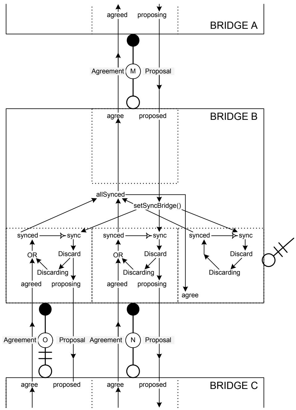
Figure 13-6—Agreements and Proposals
Figure 13-8 illustrates the extension of the Agreement mechanism to signal from Designated Ports to Root Ports as well as vice versa. To ensure that an MSTI does not connect alternate Master Ports, an Agreement is only recognized at an MSTI Port when the CIST Regional Root associated with the information matches that selected by the receiving port. Proposals, eliciting Agreements, necessarily flow from Designated Ports to Root Ports with the propagation of spanning tree information, so a new CIST Regional Root cannot transmit a Proposal directly on its MSTI Root Ports. However, updating of a CIST Designated Port's port priority vector with a new Regional Root Identifier forces the port to discard frames for all MSTIs, thus initiating the Proposal from the first Bridge nearer the MSTI Regional Root that learns of the new Regional Root.
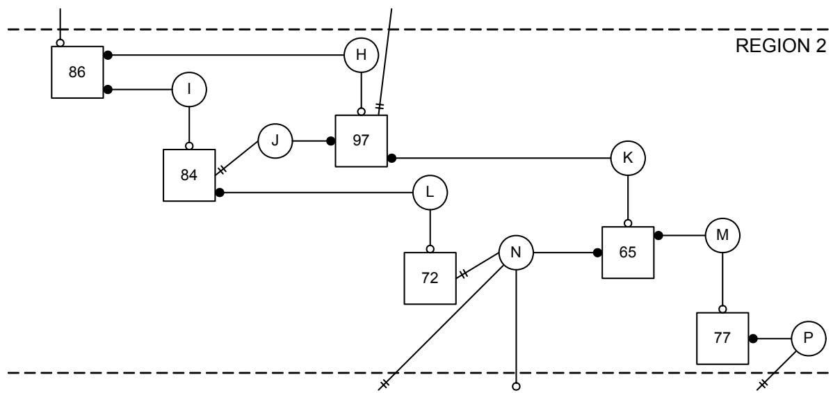
Connectivity of the CIST through Region 2
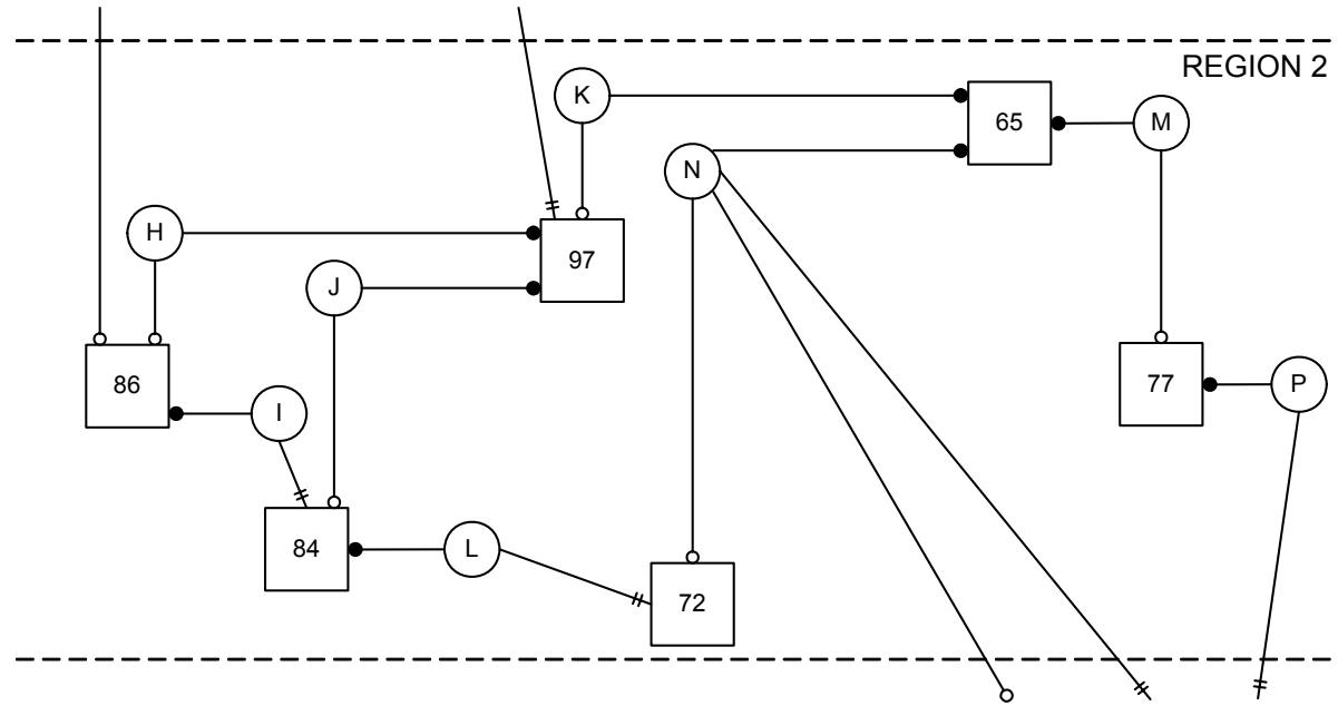
Connectivity of an MSTI through Region 2
Figure 13-7—CIST and MSTI Active Topologies in a Region
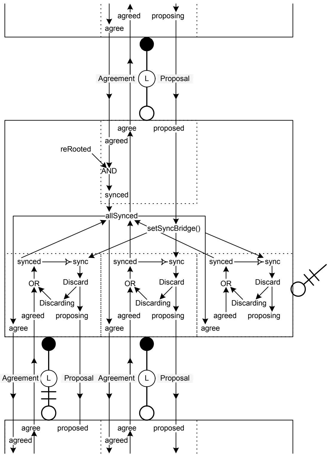
Figure 13-8—Enhanced Agreements
When an Agreement $A_{MR}$ is sent by a Root Port $P_{MR}$ on a Regional Root $M$ , it attests that the CIST Root Identifier and External Root Path Cost components of the message priority advertised on all LANs connected to the CIST by $P_{MR}$ through $M$ are the same as or worse than those accompanying $A_{MR}$ . The connectivity provided by each MSTI can be independent of that provided by the CIST within the MST Region and can therefore connect $P_{MR}$ and one or more CIST Root Ports external to but attached at the boundary of the region even as CIST connectivity within the region is interrupted in order to satisfy the conditions for generating $A_{MR}$ . The Agreement cannot therefore be generated unless all MSTI subtrees as well as the CIST subtree internal to the Region are in Agreement. To ensure that an MSTI does not connect to a CIST subtree external to the Region that does not meet the constraints on the CST priority vector components, an Agreement received at an MSTI Designated Port from a Bridge Port not internal to the Region is only recognized if the CIST Root Identifier and External Root Path Cost of the CIST root priority vector selected by the transmitting Bridge Port are equal to or worse than those selected by the receiver. Updating of a CIST Designated Port's port priority vector with a worse CIST Root Identifier and External Root Path Cost forces the port to discard frames for all MSTIs, thus initiating a Proposal that will elicit agreement.
NOTE 2—MSTI Designated Ports are forced to discard frames, as required above, through the following state machine mechanisms. The CIST Port Information machine sets the “sync” variable for all MSTIs on a transition into the UPDATE state if updating the port priority with the designated priority changes the Regional Root Identifier or replaces the CIST Root Identifier or External Path Cost with a worse tuple. The Port Role Transition machine acts on the “sync,” instructing the port to discard frames, and setting ‘synced’ and cancelling ‘sync’ when the port is discarding or an agreement is received.
NOTE 3—A “cut” in an MSTI can be transferred to the CST, either at a Designated Port attached to the same LAN as an STP Bridge or at the Root Port of a Bridge in an adjacent Region. However, if the CST priority components have already been “synced,” as they mostly likely will have if the original cut was caused by changes in physical topology within the Region, the cut will terminate there. Otherwise the transferred cut precedes a cut in the CIST, and the synced port may terminate the latter. In that way, cuts in the CST will proceed through an MST Region by the quickest tree that will carry them.
NOTE 4—In the important topology where the CIST Root Bridge is chosen to be within an MST Region, cuts are not transferred from the CIST to any MSTI in that Region. Thus, the propagation of cuts in the CIST will not disrupt MSTI connectivity in the Region.
13.17 Updating learned station location information
A spanning tree reconfiguration can cause end stations to appear to move from the point of view of any given Bridge, even if that Bridge's Port States do not change, and is signaled from the Bridge whose Port Roles have changed to others using TCN messages. MST BPDUs encode separate TCN messages for the CIST and each MSTI, and MSTP supports the optimizations specified for RSTP (17.10 of IEEE Std 802.1D). Together these facilitate removal of entries for the minimum set of Ports from the Filtering Databases associated with the spanning trees whose active topology has changed. In addition, MSTP provides, for Master Ports, the same topology change detection capability that RSTP provides for Root and Designated Ports (17.11 of IEEE Std 802.1D). Temporary cuts in the active topology, introduced to ensure that rapid Port State transitions to Forwarding do not cause loops, do not cause Filtering Database entries to be flushed throughout the network, unless they are accompanied by Port Role changes. MSTP provides the same capabilities as RSTP with respect to updating learned station location information (17.11 of IEEE Std 802.1D).
Changes in the active topology of any MSTI do not change end station locations for the CIST or any other MSTI, unless the underlying changes in the physical topology that gave rise to the reconfiguration also cause those trees to reconfigure. Changes to the CST, i.e., the connectivity provided by the CIST between MST Regions, can cause end station location changes for all trees. Changes to an IST can cause CST end station location changes but do not affect MSTIs in that Region unless those trees also reconfigure.
NOTE 1—The shorthand terms “end station locations for a given tree,” “the CST,” and “an IST” are used to mean “the apparent location of end stations as recorded by filtering databases associated with the given tree,” “the connectivity provided by the CIST between and not internal to MST Regions,” and “the connectivity provided by the CIST internal to a given MST Region” respectively.
On receipt of a CIST TCN Message from a Bridge Port not internal to the Region, or on a change in Port Role for a Bridge Port not internal to the Region, TCN Messages are transmitted through each of the other Ports of the receiving Bridge for each MSTI and the Filtering Databases for those ports are flushed.
NOTE 2—TCN Messages for the CIST are always encoded in the same way, irrespective of whether they are perceived to have originated from topology changes internal to the Region or outside it. This allows RSTP Bridges whose Root Ports attach to a LAN within an MST Region to receive these TCN Messages correctly.
NOTE 3—The Port receiving a CIST TCN Message from another Bridge Port external to the Region can be a Master Port, a Designated Port attached to the same LAN as an STP Bridge, or a Designated Port attached to a LAN that is within the Region but is attached to by the Root Ports of Bridges in other Regions.
13.18 MSTP and point-to-point links
MSTP uses the adminPointToPointMAC and operPointToPointMAC parameters (6.4.3 of IEEE Std 802.1D) to allow the point-to-point status of LANs to be manipulated administratively and the operational state to be signaled to the MSTP state machines. This use, paralleling that of RSTP (17.12 of IEEE Std 802.1D), facilitates use of the Agreement mechanism (13.16) to enable rapid Forwarding Port State transitions.
13.19 Multiple Spanning Tree state machines
The operation of the Multiple Spanning Tree Protocol is represented by the following common set of state machines:
a) A Port Timers state machine for each Port (13.27)
b) A Port Protocol Migration state machine for each Port (13.29)
c) A Port Receive state machine for each Port (13.28)
d) A Port Transmit state machine for each Port (13.31)
e) A Bridge Detection state machine for each Port (13.30)
with the following set for the CIST and each MSTI:
f) A Port Information state machine for each Port (13.32)
g) A Port Role Selection state machine for the Bridge (13.33)
h) A Port Role Transitions state machine for each Port (13.34)
i) A Port State Transition state machine for each Port (13.35)
j) A Topology Change state machine for each Port (13.36)
The operation of each state machine and its associated variable and procedural definitions is specified in detail in 13.20 through 13.36. Each is modeled on the corresponding state machine for RSTP as described in Clause 17 of IEEE Std 802.1D. Modifications:
1) Support both the CIST and the MSTIs
2) Use the extended spanning tree priority vector definition and calculations for the CIST (13.10)
3) Provide communication between the CIST state machines and the MSTI state machines as required by 13.16, 13.19, and 13.17.
All references to named variables or procedures in the specification of the state machines are to those corresponding to the instance of the state machine using the function unless explicit reference is made to the CIST or given MSTIs.
NOTE—Individual MSTIs do not implement their own Port Transmit state machine but signal the need to transmit to a single Port Transmit State machine by setting the newInfoMsti variable. The procedures used by this machine transmit information for the CIST and all MSTIs in a single BPDU.
Figure 13-9 illustrates the state machines, their state variables, and communication between state machines. This overview diagram is not itself a state machine but serves to illustrate the principal variables that are used to communicate between the individual machines and the variables local to each machine Figure 13-10 describes its notation.
Should any conflict exist between the text in Clause 13 and the text in other parts of the standard (in particular, Clause 12, Clause 14, and Annex A), the text in Clause 13 takes precedence.
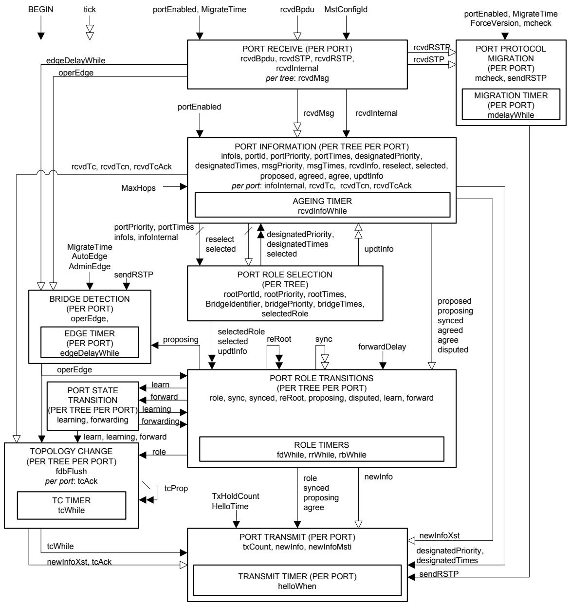
NOTE: For convenience all timers are collected together into one state machine.
Figure 13-9—MSTP state machines—overview and relationships
13.20 Notational conventions used in state diagrams
The notational conventions used in the specification of MSTP are identical to those used in the specification of RSTP and defined in 17.16 of IEEE Std 802.1D.
13.21 State machine timers
Each state machine timer is as specified in 17.17 of IEEE Std 802.1D.
NOTATION:
Variables are shown both within the machine where they are principally used and between machines where they are used to communicate information. In the latter case they are shown with a variety of arrow styles, running from one machine to another, that provide an overview of how the variables are typically used:
ABBREVIATIONS:
BDM:
Bridge Detection Machine
PIM:
Port Information Machine
PPM:
Port Protocol Migration Machine
PRS:
Port Role Selection Machine
PRT:
Port Role Transitions Machine
PRX:
Port Receive Machine
PST:
Port State Transitions Machine
PTI:
Port Timers Machine
PTX:
Port Transmit Machine
TCM:
Topology Change Machine
Not changed by the target machine. Where the state machines are both per Port, this variable communicates between machine instances for the same port.
Set (or cleared) by the originating machine, cleared (or set) by the target machine. Where the state machines are both per Port, this variable communicates between machine instances for the same port.
As above except that the originating per port machine instance communicates with multiple port machine instances (by setting or clearing variables owned by those Ports).
As above except that multiple per Port instances communicate with (an)other instance(s) (by setting or clearing variables owned by the originating Ports).
Figure 13-10—MSTP overview notation
One instance of the following shall be implemented per-Port:
a) mdelayWhile
b) helloWhen
c) edgeDelayWhile
One instance per-Port of the following shall be implemented for the CIST and one per-Port for each MSTI:
d) fdWhile
e) rrWhile
f) rbWhile
g) tcWhile
h) rcvdInfoWhile
13.22 MSTP performance parameters
These parameters are not modified by the operation of MSTP but are treated as constants by the MSTP state machines and the associated variables (13.23, 13.24) and conditions (13.25). They may be modified by management action.
The spanning tree priority vectors and Port Role assignments for a Tree shall be recomputed, as specified by the operation of the Port Role Selection state machine (13.33) by clearing selected (13.24) and setting reselect (13.24) for any Port or Ports of a Tree for which the following parameters are modified:
a) Bridge Identifier Priority (13.23.2)
b) Port Identifier Priority (13.22)
c) ExternalPortPathCost (13.22)
d) InternalPortPathCost (13.22)
If the Transmit Hold Count is modified, the value of txCount (13.24) for all Ports shall be set to zero.
The MSTP specification permits changes in other performance parameters without exceptional actions.
The following parameters are as specified in 17.13 of IEEE Std 802.1D for RSTP. A single value of each parameter applies to the MST Bridge as a whole, including all Ports and all CIST and MSTI state machines.
e) Force Protocol Version
f) Bridge Forward Delay
g) Transmit Hold Count
h) Migrate Time
i) Bridge Max Age
The following parameter is as specified for RSTP but has been renamed in this specification and is managed separately for each Port:
j) Port Hello Time (specified as Bridge Hello Time in 17.13 of IEEE Std 802.1D)
The following parameters are as specified in 17.13 of IEEE Std 802.1D for RSTP but may be managed separately for each Port.
k) Admin Edge Port
1) Ageing Time
m) Auto Edge
n) Port Identifier Priority
The recommended default value for Admin Edge Port is FALSE.
The following parameter is additional to those specified for RSTP. A single value applies to all Spanning Trees within an MST Region (the CIST and all MSTIs) for which the Bridge is the Regional Root.
o) MaxHops (13.22.1)
The following parameter is as specified for RSTP but has been renamed for clarity in this specification. One value per-Port applies to the CIST.
p) ExternalPortPathCost (specified as PortPathCost in 17.13 of IEEE Std 802.1D)
The following parameter is additional to those specified for RSTP and may be managed separately for the CIST and for each MSTI per-Port.
q) InternalPortPathCost
13.22.1 MaxHops
MaxHops defines the initial value of remainingHops for MSTI information generated at the boundary of an MSTI region (see 13.23.7). Its value is determined by management.
13.23 Per-Bridge variables
Per-Bridge variable(s) perform the functions described in 17.18 of IEEE Std 802.1D but have enhanced or extended specifications or considerations.
A single instance of each of the following variables applies to the CIST and to all MSTIs.
a) BEGIN (13.23.1)
b) MstConfigId (13.23.8)
NOTE—MstConfigId is not specified in 17.18 of IEEE Std 802.1D.
There is one instance per-Bridge of each of the following for the CIST, and one for each MSTI.
c) BridgeIdentifier (13.23.2)
d) BridgePriority (13.23.3)
e) BridgeTimes (13.23.4)
f) rootPortId (13.23.5)
g) rootPriority (13.23.6)
h) rootTimes (13.23.7)
13.23.1 BEGIN
This Boolean variable is controlled by the system initialization process. A value of TRUE causes all CIST and MSTI state machines, including per-Port state machines, to continuously execute their initial state. A value of FALSE allows all state machines to perform transitions out of their initial state, in accordance with the relevant state machine definitions.
Changes to any of the following parameters cause BEGIN to be asserted for the state machines for the Bridge, for all trees, and for each Port:
a) The MST Configuration Identifier
b) Force Protocol Version.
13.23.2 Bridgeldentifier
The unique Bridge Identifier assigned to this Bridge for this tree (CIST or MSTI).
The 12-bit system ID extension component of a Bridge Identifier (9.2.5 of IEEE Std 802.1D) shall be set to zero for the CIST, and to the value of the MSTID for an MSTI, thus allocating distinct Bridge Identifiers to the CIST and each MSTI all based on the use of a single Bridge Address component value for the MST Bridge as a whole.
NOTE—This convention is used to convey the MSTID for each MSTI Configuration Message encoded in an MST BPDU.
The four most significant bits of the Bridge Identifier (the settable Priority component) for the CIST and for each MSTI can be modified independently of the setting of those bits for all other trees, as a part of allowing full and independent configuration control to be exerted over each Spanning Tree instance.
13.23.3 BridgePriority
For the CIST, the value of the CIST bridge priority vector, as defined in 13.10. The CIST Root Identifier, CIST Regional Root Identifier, and Designated Bridge Identifier components are all equal to the value of the CIST Bridge Identifier. The remaining components (External Root Path Cost, Internal Root Path Cost, and Designated Port Identifier) are set to zero.
For a given MSTI, the value of the MSTI bridge priority vector, as defined in 13.11. The MSTI Regional Root Identifier and Designated Bridge Identifier components are equal to the value of the MSTI Bridge Identifier (13.23.2). The remaining components (MSTI Internal Root Path Cost, Designated Port Identifier) are set to zero.
BridgePriority is used by updtRolesTree() in determining the value of the rootPriority variable (see 13.23.6).
13.23.4 BridgeTimes
For the CIST, BridgeTimes comprises:
a) The current values of Bridge Forward Delay and Bridge Max Age (see Table 17-1 of IEEE Std 802.1D). These parameter values are determined only by management;
b) A Message Age value of zero.
c) The current value of MaxHops (13.22). This parameter value is determined only by management.
For a given MSTI, BridgeTimes comprises:
d) The current value of MaxHops (13.22). This parameter value is determined only by management;
BridgeTimes is used by updtRolesTree() in determining the value of the RootTimes variable (13.23.7).
13.23.5 rootPortId
For the CIST, the Port Identifier of the Root Port, and a component of the CIST root priority vector (13.10).
For a given MSTI, the Port Identifier of the Root Port, and a component of the MSTI root priority vector (13.11).
13.23.6 rootPriority
For the CIST, the CIST Root Identifier, CIST External Root Path Cost, CIST Regional Root Identifier, CIST Internal Root Path Cost, Designated Bridge Identifier, and Designated Port Identifier components of the Bridge's CIST root priority vector (13.10).
For a given MSTI, the MSTI Regional Root Identifier, MSTI Internal Root Path Cost, MSTI Designated Bridge Identifier, and MSTI Designated Port Identifier components of the Bridge's CIST root priority vector (13.11).
13.23.7 rootTimes
For the CIST, the Bridge's timer parameter values (Message Age, Max Age, Forward Delay, and remainingHops). The values of these timers are derived (see 13.26.23) from the values stored in the CIST's portTimes parameter (13.24.13) for the Root Port or from BridgeTimes (13.23.4).
For a given MSTI, the value of remainingHops derived (13.26.23) from the value stored in the MSTI's portTimes parameter (13.24.13) for the Root Port or from BridgeTimes (13.23.4).
13.23.8 MstConfigId
The value of the MST Configuration Identifier (13.7) corresponding to the Bridge's current MST Region Configuration.
13.24 Per-Port variables
The following variables perform the function specified in 17.19 of IEEE Std 802.1D. A single per-Port instance applies to the CIST and to all MSTIs:
a) ageingTime
b) operEdge
c) portEnabled
d) tick
e) txCount
A single per-Port instance of the following variable(s) not specified in IEEE Std 802.1D applies to the CIST and to all MSTIs:
f) infoInternal (13.24.4)
g) rcvdInternal (13.24.14)
h) restrictedRole (13.25.14)
i) restrictedTcn (13.25.15)
A single per-Port instance of the following variable(s) not specified in IEEE Std 802.1D applies to all MSTIs:
j) newInfoMsti (13.24.8)
The following variables perform the function specified in 17.19 of IEEE Std 802.1D. A single per-Port instance is used by all state machines:
k) mcheck
l) rcvdBpdu
m) rcvdRSTP
n) rcvdSTP
o) rcvdTcAck
p) rcvdTcn
q) sendRSTP
r) tcAck
The following variable is specified in 17.19 of IEEE Std 802.1D; however, its use in this standard is modified as indicated. There is one instance per-Port of this variable for the CIST and one per-Port for each MSTI:
s)fdbFlush. In addition to the definition offdbFlush contained in IEEE Std 802.1D, setting thefdbFlush variable does not result in flushing of filtering database entries in the case that the Port is an Edge Port (i.e., operEdge is TRUE).
NOTE—It will be necessary to update the definition of this variable in a future revision of IEEE Std 802.1D to reflect this additional constraint.
The following variables are as specified in 17.19 of IEEE Std 802.1D. There is one instance per-Port of each variable for the CIST and one per-Port for each MSTI:
t) agree
u) disputed
v) forward
w) forwarding
x) infoIs
y) learn
z) learning
aa) proposed
ab) proposing
ac) rcvdInfo
ad) rcvdMsg
ae) rcvdTc
af) reRoot
ag) reselect
ah) selected
ai) tcProp
aj) updtInfo
The following variables perform the functions described in 17.19 of IEEE Std 802.1D but have enhanced or extended specifications or considerations. There is one instance per-Port of each variable for the CIST, and one per-Port for each MSTI:
ak) agreed (13.24.1)
al) designatedPriority (13.24.2)
am) designatedTimes (13.24.3)
an) msgPriority (13.24.9)
ao) msgTimes (13.24.10)
ap) portId (13.24.11)
aq) portPriority (13.24.12)
ar) portTimes (13.24.13)
as) role (13.24.15)
at) selectedRole (13.24.16)
au) sync (13.24.17)
av) synced (13.24.18)
The following variables perform the related functions described in 17.19 of IEEE Std 802.1D but have extended specifications. There is one instance per-Port of each variable for the CIST:
aw) newInfo (13.24.7)
The following variable(s) are additional to those specified in 17.19 of IEEE Std 802.1D. There is one instance per-Port of each variable for each MSTI:
ax) master (13.24.5)
ay) mastered (13.24.6)
13.24.1 agreed
A Boolean value indicating that a Configuration Message has been received from another Bridge attached to the same LAN indicating Agreement that all Port States for the given tree of all other Bridges attached to the same LAN as this Port are known to be likewise compatible with a loop free active topology determined by this Bridge's priority vectors and, in the absence of further communication with this Bridge, will remain compatible within the design probabilities of protocol failure due to repeated BPDU loss (13.16, 13.19).
13.24.2 designatedPriority
For the CIST and a given Port, the CIST Root Identifier, External Root Path Cost, Regional Root Identifier, Internal Root Path Cost, Designated Bridge Identifier, and Designated Port Identifier components of the Port's CIST designated priority vector, as defined in 13.10.
For a given MSTI and Port, the Regional Root Identifier, Internal Root Path Cost, Designated Bridge Identifier, and Designated Port Identifier components of the Port's designated priority vector, as defined in 13.11.
13.24.3 designatedTimes
For the CIST and a given Port, the set of timer parameter values (Message Age, Max Age, Forward Delay, and remainingHops) that are used to update Port Times when updtInfo is set. These timer parameter values are used in BPDUs transmitted from the Port. The value of designatedTimes is copied from the CIST rootTimes Parameter (13.23.7) by the operation of the updtRolesTree() procedure.
For a given MSTI and Port, the value of remainingHops used to update this MSTI's portTimes parameter when updtInfo is set. This timer parameter value is used in BPDUs transmitted from the Port. The value of designatedTimes is copied from this MSTI's rootTimes parameter (13.23.7) by the operation of the updtRolesTree() procedure.
13.24.4 infolnternal
If infoIs is Received, indicating that the port has received current information from the Designated Bridge for the attached LAN, infoInternal is set if that Designated Bridge is in the same MST Region as the receiving Bridge and reset otherwise.
13.24.5 master
A Boolean variable used to determine the value of the Master flag for this MSTI and Port in transmitted MST BPDUs.
Set TRUE if the Port Role for the MSTI and Port is Root Port or Designated Port, and the Bridge has selected one of its Ports as the Master Port for this MSTI or the mastered flag is set for this MSTI for any other Bridge Port with a Root Port or Designated Port Role. Set FALSE otherwise.
13.24.6 mastered
A Boolean variable used to record the value of the Master flag for this MSTI and Port in MST BPDUs received from the attached LAN.
NOTE—master and mastered signal the connection of the MSTI to the CST via the Master Port throughout the MSTI. These variables and their supporting procedures do not affect the connectivity provided by this revision of this standard but permit future enhancements to MSTP providing increased flexibility in the choice of Master Port without abandoning plug-and-play network migration. They are, therefore, omitted from the overviews of protocol operation, including Figure 13-9.
13.24.7 newInfo
A Boolean variable set TRUE if a BPDU conveying changed CIST information is to be transmitted. It is set FALSE by the Port Transmit state machine.
13.24.8 newInfoMsti
A Boolean variable set TRUE if a BPDU conveying changed MSTI information is to be transmitted. It is set FALSE by the Port Transmit state machine.
13.24.9 msgPriority
For the CIST and a given Port, the CIST Root Identifier, External Root Path Cost, Regional Root Identifier, Internal Root Path Cost, Designated Bridge Identifier, and Designated Port Identifier components of the CIST message priority vector conveyed in a received BPDU, as defined in 13.10.
For a given MSTI and Port, the Regional Root Identifier, Internal Root Path Cost, Designated Bridge Identifier, and Designated Port Identifier components of the MSTI message priority vector, as defined in 13.11 and conveyed in a received BPDU for this MSTI.
13.24.10 msgTimes
For the CIST and a given Port, the timer parameter values (Message Age, Max Age, Forward Delay, Hello Time, and remainingHops) conveyed in a received BPDU. If the BPDU is an ST or RST BPDU without MSTP parameters, remainingHops is set to MaxHops.
For a given MSTI and Port, the value of remainingHops received in the same BPDU as the message priority components of this MSTI's msgPriority parameter.
13.24.11 portld
The Port Identifier for this Port. This variable forms a component of the port priority and designated priority vectors (13.10, 13.11).
The four most significant bits of the Port Identifier (the settable Priority component) for the CIST and for each MSTI can be modified independently of the setting of those bits for all other trees, as a part of allowing full and independent configuration control to be exerted over each Spanning Tree instance.
13.24.12 portPriority
For the CIST and a given Port, the CIST Root Identifier, External Root Path Cost, Regional Root Identifier, Internal Root Path Cost, Designated Bridge Identifier, and Designated Port Identifier components of the Port's port priority vector, as defined in 13.10.
For a given MSTI and Port, the Regional Root Identifier, Internal Root Path Cost, Designated Bridge Identifier, and Designated Port Identifier components of the Port's MSTI port priority vector, as defined in 13.11.
13.24.13 portTimes
For the CIST and a given Port, the Port's timer parameter values (Message Age, Max Age, Forward Delay, Hello Time, and remainingHops). The Hello Time timer parameter value is used in BPDUs transmitted from the Port.
For a given MSTI and Port, the value of remainingHops for this MSTI in BPDUs transmitted through the Port.
13.24.14 rcvdInternal
A Boolean variable set TRUE by the Receive Machine if the BPDU received was transmitted by a Bridge in the same MST Region as the receiving Bridge.
13.24.15 role
The assigned Port Role. The port's role is either DisabledPort, RootPort, DesignatedPort, AlternatePort, BackupPort, or MasterPort.
NOTE—The role of MasterPort is introduced for MSTIs for a Port where the CIST Port Role is RootPort and the spanning tree information received is from another MST Region. A MSTI Master Port forms part of the stable active topology for frames allocated to that MSTI, just as the CIST Root Port forwards frames allocated to the CIST. The Port State for each MSTI may differ as required to suppress temporary loops.
13.24.16 selectedRole
A newly computed role for the Port.
13.24.17 sync
A Boolean value. Set TRUE to force the Port State to be compatible with the loop free active topology determined by the priority vectors held by this Bridge (13.16,13.19) for this tree (CIST, or MSTI), by transitioning the Port State to Discarding and soliciting an Agreement if possible, if the Port is not already synchronized (13.24.18).
13.24.18 synced
A Boolean value. TRUE only if the Port State is compatible with the loop free active topology determined by the priority vectors held by this Bridge for this tree (13.16, 13.19).
13.25 State machine conditions and parameters
The following boolean variable evaluations are defined for notational convenience in the state machines. These definitions also serve to highlight those cases where a state transition for one tree (CIST or MSTI) depends on the state of the variables of one or more other trees.
The following conditions and parameters are as specified in 17.20 of IEEE Std 802.1D:
a) AdminEdge (default value FALSE)
b) AutoEdge (default value TRUE)
c) EdgeDelay
d) forwardDelay
e) MigrateTime
f) reRooted
g) rstpVersion
h) stpVersion
i) TxHoldCount
The following conditions and parameters are similar to those specified in 17.20 of IEEE Std 802.1D but have enhanced or extended specifications or considerations:
j) allSynced (13.25.1)
k) FwdDelay (13.25.6)
1) HelloTime (13.25.7)
m) MaxAge (13.25.8)
The following conditions and parameters are additional to those described in 17.20 of IEEE Std 802.1D:
n) allTransmitReady (13.25.2)
o) cist (13.25.3)
p) cistRootPort (13.25.4)
q) cistDesignatedPort (13.25.5)
r) mstiDesignatedOrTCpropagatingRootPort (13.25.9)
s) mstiMasterPort (13.25.10)
t) rcvdAnyMsg (13.25.11)
u) rcvdCistMsg (13.25.12)
v) rcvdMstiMsg (13.25.13)
w) restrictedRole (13.25.14)
x) restrictedTcn (13.25.15)
y) updtCistInfo (13.25.16)
z) updtMstiInfo (13.25.17)
13.25.1 allSynced
The condition allSynced is TRUE for a given Port, for a given Tree, if and only if
a) For all Ports for the given Tree, selected is TRUE, the Port's role is the same as its selectedRole, and updtInfo is FALSE; and
b) The role of the given Port is
1) Root Port or Alternate Port and synced is TRUE for all Ports for the given Tree other than the Root Port; or
2) Designated Port and synced is TRUE for all Ports for the given Tree other than the given Port; or
3) Master Port and synced is TRUE for all Ports for the given Tree other than the given Port.
13.25.2 allTransmitReady
TRUE, if and only if, for the given Port for all Trees
a) selected is TRUE; and
b) updtInfo is FALSE.
13.25.3 cist
TRUE only for CIST state machines; i.e., FALSE for MSTI state machine instances.
13.25.4 cistRootPort
TRUE if the CIST role for the given Port is RootPort.
13.25.5 cistDesignatedPort
TRUE if the CIST role for the given Port is DesignatedPort.
13.25.6 FwdDelay
The Forward Delay component of the CIST's designatedTimes parameter (13.24.3).
13.25.7 HelloTime
The Hello Time component of the CIST's portTimes parameter (13.24.13) with the recommended default value given in 13.37.2.
13.25.8 MaxAge
The Max Age component of the CIST's designated Times parameter (13.24.3).
13.25.9 mstiDesignatedOrTCpropagatingRootPort
TRUE if the role for any MSTI for the given Port is either:
a) DesignatedPort; or
b) RootPort, and the instance for the given MSTI and Port of the tcWhile timer is not zero.
13.25.10 mstiMasterPort
TRUE if the role for any MSTI for the given Port is MasterPort.
13.25.11 rcvdAnyMsg
TRUE for a given Port if rcvdMsg is TRUE for the CIST or any MSTI for that Port.
13.25.12 rcvdCistMsg
TRUE for a given Port if and only if rcvdMsg is TRUE for the CIST for that Port.
13.25.13 rcvdMstiMsg
TRUE for a given Port and MSTI if and only if rcvdMsg is FALSE for the CIST for that Port and rcvdMsg is TRUE for the MSTI for that Port.
13.25.14 restrictedRole
A Boolean value set by management. If TRUE causes the Port not to be selected as Root Port for the CIST or any MSTI, even it has the best spanning tree priority vector. Such a Port will be selected as an Alternate Port after the Root Port has been selected. This parameter should be FALSE by default. If set, it can cause lack of spanning tree connectivity. It is set by a network administrator to prevent bridges external to a core region of the network influencing the spanning tree active topology, possibly because those bridges are not under the full control of the administrator.
13.25.15 restrictedTcn
A Boolean value set by management. If TRUE causes the Port not to propagate received topology change notifications and topology changes to other Ports. This parameter should be FALSE by default. If set it can cause temporary loss of connectivity after changes in a spanning trees active topology as a result of persistent incorrectly learned station location information. It is set by a network administrator to prevent bridges external to a core region of the network, causing address flushing in that region, possibly because those bridges are not under the full control of the administrator or MAC_Operational for the attached LANs transitions frequently.
13.25.16 updtCistInfo
TRUE for a given Port if and only if updtInfo is TRUE for the CIST for that Port.
13.25.17 updtMstilinfo
TRUE for a given Port and MSTI if and only if updtInfo is TRUE for the MSTI for that Port or updtInfo is TRUE for the CIST for that Port.
NOTE—The dependency of rcvdMstiMsg and updtMstiInfo on CIST variables for the Port reflects the fact that MSTIs exist in a context of CST parameters. The state machines ensure that the CIST parameters from received BPDUs are processed and updated prior to processing MSTI information.
13.26 State machine procedures
The following procedures perform the functions specified in 17.21 of IEEE Std 802.1D for the CIST state machines:
a) txTcn()
The following procedures perform the functions specified in 17.21 of IEEE Std 802.1D for the CIST or any given MSTI instance:
b) disableForwarding()
c) disableLearning()
d) enableForwarding()
e) enableLearning()
f) recordPriority()
The following procedures perform the general functions described in 17.21 of IEEE Std 802.1D for both the CIST and the MSTI state machines or specifically for the CIST or a given MSTI but have enhanced or extended specifications or considerations:
g) betterorsameInfo(newInfoIs) (13.26.1)
h) clearReselectTree() (13.26.3)
i) newTcWhile() (13.26.5)
j) rcvInfo() (13.26.6)
k) recordAgreement() (13.26.7)
1) recordDispute() (13.26.8)
m) recordProposal() (13.26.10)
n) recordTimes() (13.26.11)
o) setReRootTree(13.26.13)
p) setSelectedTree() (13.26.14)
q) setSyncTree() (13.26.15)
r) setTcFlags() (13.26.16)
s) setTcPropTree() (13.26.17)
t) txConfig() (13.26.19)
u) txMstp() (13.26.20)
NOTE 1—The equivalent procedure to txMstp() in IEEE Std 802.1D is called txRstp().
v) updtBPDUVersion() (13.26.21)
w) updtRcvdInfoWhile() (13.26.22)
x) updtRolesTree() (13.26.23)
y) updtRolesDisabledTree() (13.26.24)
The following procedures perform functions additional to those described in 17.21 of IEEE Std 802.1D for both the CIST and the MSTI state machines or for the CIST or a given MSTI specifically:
z) clearAllRcvdMsgs() (13.26.2)
aa) fromSameRegion() (13.26.4)
ab) recordMastered() (13.26.9)
ac) setRcvdMsgs() (13.26.12)
ad) syncMaster() (13.26.18)
All references to named variables in the specification of procedures are to instances of the variables corresponding to the instance of the state machine using the function, i.e., to the CIST or the given MSTI as appropriate. References to the forwarding and learning functions for a Port apply to all and only those Filtering Databases associated with that specific tree.
13.26.1 betterorsamelinfo(newInfols)
Returns TRUE if, for a given Port and Tree (CIST, or MSTI), either
a) The procedure's parameter newInfoIs is Received, and infoIs is Received and the msgPriority vector is better than or the same as (13.10) the portPriority vector; or,
b) The procedure's parameter newInfoIs is Mine, and infoIs is Mine and the designatedPriority vector is better than or the same as (13.10) the portPriority vector.
Returns False otherwise.
NOTE—This procedure is not invoked (in the case of a MSTI) if the received BPDU carrying the MSTI information was received from another MST Region. In that event, the Port Receive Machine (using setRcvdMsgs()) does not set rcvdMsg for any MSTI, and the Port Information Machine's SUPERIOR_DESIGNATED state is not entered.
13.26.2 clearAllRcvdMsgs()
Clears rcvdMsg for the CIST and all MSTIs, for this Port.
13.26.3 clearReselectTree()
Clears reselect for the tree (the CIST or a given MSTI) for all Ports of the Bridge.
13.26.4 fromSameRegion()
Returns TRUE if rcvdRSTP is TRUE, and the received BPDU conveys a MST Configuration Identifier that matches that held for the Bridge. Returns FALSE otherwise.
13.26.5 newTcWhile()
If the value of tcWhile is zero and sendRSTP is TRUE, this procedure sets the value of tcWhile to HelloTime plus one second and sets either newInfo TRUE for the CIST or newInfoMsti TRUE for a given MSTI. The value of HelloTime is taken from the CIST's portTimes parameter (13.24.13) for this Port.
If the value of tcWhile is zero and sendRSTP is FALSE, this procedure sets the value of tcWhile to the sum of the Max Age and Forward Delay components of rootTimes and does not change the value of either newInfoCist or newInfoMsti.
Otherwise the procedure takes no action.
13.26.6 rcvInfo()
Decodes received BPDUs. Sets rcvdTcn and sets rcvdTc for each and every MSTI if a TCN BPDU has been received, and extracts the message priority and timer values from the received BPDU storing them in the msgPriority and msgTimes variables.
Returns SuperiorDesignatedInfo if, for a given Port and Tree (CIST, or MSTI):
a) The received CIST or MSTI message conveys a Designated Port Role, and
1) The message priority (msgPriority—13.24.9) is superior (13.10 or 13.11) to the Port's port priority vector, or
2) The message priority is the same as the Port's port priority vector, and any of the received timer parameter values (msgTimes—13.24.10) differ from those already held for the Port (portTimes—13.24.13).
Otherwise, returns RepeatedDesignatedInfo if, for a given Port and Tree (CIST, or MSTI):
b) The received CIST or MSTI message conveys a Designated Port Role, and
1) A message priority vector and timer parameters that are the same as the Port's port priority vector and timer values; and
2) infoIs is Received.
Otherwise, returns InferiorDesignatedInfo if, for a given Port and Tree (CIST, or MSTI):
c) The received CIST or MSTI message conveys a Designated Port Role.
Otherwise, returns InferiorRootAlternateInfo if, for a given Port and Tree (CIST, or MSTI):
d) The received CIST or MSTI message conveys a Root Port, Alternate Port, or Backup Port Role and a CIST or MSTI message priority that is the same as or worse than the CIST or MSTI port priority vector.
Otherwise, returns OtherInfo.
NOTE—A Configuration BPDU implicitly conveys a Designated Port Role.
13.26.7 recordAgreement()
For the CIST and a given Port, if rstpVersion is TRUE, operPointToPointMAC (6.4.3) is TRUE, and the received CIST Message has the Agreement flag set, the CIST agreed flag is set, and the CIST proposing flag is cleared. Otherwise the CIST agreed flag is cleared. Additionally, if the CIST message was received from a Bridge in a different MST Region, i.e., the rcvdInternal flag is clear, the agreed and proposing flags for this Port for all MSTIs are set or cleared to the same value as the CIST agreed and proposing flags. If the CIST message was received from a Bridge in the same MST Region, the MSTI agreed and proposing flags are not changed.
For a given MSTI and Port, if operPointToPointMAC (6.4.3) is TRUE, and
a) The message priority vector of the CIST Message accompanying the received MSTI Message (i.e., received in the same BPDU) has the same CIST Root Identifier, CIST External Root Path Cost, and Regional Root Identifier as the CIST port priority vector, and
b) The received MSTI Message has the Agreement flag set,
the MSTI agreed flag is set and the MSTI proposing flag is cleared. Otherwise the MSTI agreed flag is cleared.
NOTE—MSTI Messages received from Bridges external to the MST Region are discarded and not processed by recordAgreement() or recordProposal().
13.26.8 recordDispute()
For the CIST and a given port, if the CIST message has the learning flag set:
a) The disputed variable is set; and
b) The agreed variable is cleared.
Additionally, if the CIST message was received from a Bridge in a different MST region (i.e., if the rcvdInternal flag is clear), then for all the MSTIs:
c) The disputed variable is set; and
d) The agreed variable is cleared.
For a given MSTI and port, if the received MSTI message has the learning flag set:
e) The disputed variable is set; and
f) The agreed variable is cleared.
13.26.9 recordMastered()
For the CIST and a given Port, if the CIST message was received from a Bridge in a different MST Region, i.e. the rcvdInternal flag is clear, the mastered variable for this Port is cleared for all MSTIs.
For a given MSTI and Port, if the MSTI message was received on a point-to-point link and the MSTI Message has the Master flag set, set the mastered variable for this MSTI. Otherwise reset the mastered variable.
13.26.10 recordProposal()
For the CIST and a given Port, if the received CIST Message conveys a Designated Port Role, and has the Proposal flag set, the CIST proposed flag is set. Otherwise the CIST proposed flag is not changed. Additionally, if the CIST Message was received from a Bridge in a different MST Region, i.e., the rcvdInternal flag is clear, the proposed flags for this Port for all MSTIs are set or cleared to the same value as the CIST proposed flag. If the CIST message was received from a Bridge in the same MST Region, the MSTI proposed flags are not changed.
For a given MSTI and Port, if the received MSTI Message conveys a Designated Port Role, and has the Proposal flag set, the MSTI proposed flag is set. Otherwise the MSTI proposed flag is not changed.
13.26.11 recordTimes()
For the CIST and a given Port, sets portTimes' Message Age, Max Age, Forward Delay, and remainingHops to the received values held in msgTimes and portTimes' Hello Time to msgTimes' Hello Time if that is greater than the minimum specified in the Compatibility Range column of Table 17-1 of IEEE Std 802.1D, and to that minimum otherwise.
For a given MSTI and Port, sets portTime's remainingHops to the received value held in msgTimes.
13.26.12 setRcvdMsgs()
Sets rcvdMsg for the CIST, and makes the received CST or CIST message available to the CIST Port Information state machines.
Additionally, and if and only if rcvdInternal is set, sets rcvdMsg for each and every MSTI for which a MSTI message is conveyed in the BPDU, and makes available each MSTI message and the common parts of the CIST message priority (the CIST Root Identifier, External Root Path Cost, and Regional Root Identifier) to the Port Information state machine for that MSTI.
13.26.13 setReRootTree()
Sets reRoot TRUE for this tree (the CIST or a given MSTI) for all Ports of the Bridge.
13.26.14 setSelectedTree()
Sets selected TRUE for this tree (the CIST or a given MSTI) for all Ports of the Bridge if reselect is FALSE for all Ports in this tree. If reselect is TRUE for any Port in this tree, this procedure takes no action.
13.26.15 setSyncTree()
Sets sync TRUE for this tree (the CIST or a given MSTI) for all Ports of the Bridge.
13.26.16 setTcFlags()
For the CIST and a given Port:
a) If the Topology Change Acknowledgment flag is set for the CIST in the received BPDU, sets rcvdTcAck TRUE.
b) If rcvdInternal is clear and the Topology Change flag is set for the CIST in the received BPDU, sets rcvdTc TRUE for the CIST and for each and every MSTI.
c) If rcvdInternal is set, sets rcvdTc for the CIST if the Topology Change flag is set for the CIST in the received BPDU.
For a given MSTI and Port, sets rcvdTc for this MSTI if the Topology Change flag is set in the corresponding MSTI message.
13.26.17 setTcPropTree()
If and only if restrictedTcn is FALSE for the Port that invoked the procedure, sets tcProp TRUE for the given tree (the CIST or a given MSTI) for all other Ports.
13.26.18 syncMaster()
For all MSTIs, for each Port that has infoInternal set:
a) Clears the agree, agreed, and synced variables; and
b) Sets the sync variable.
13.26.19 txConfig()
Transmits a Configuration BPDU. The first four components of the message priority vector (13.24.9) conveyed in the BPDU are set to the value of the CIST Root Identifier, External Root Path Cost, Bridge Identifier, and Port Identifier components of the CIST's designatedPriority parameter (13.24.2) for this Port. The topology change flag is set if (tcWhile != 0) for the Port. The topology change acknowledgment flag is set to the value of TcAck for the Port. The remaining flags are set to zero. The value of the Message Age, Max Age, and Fwd Delay parameters conveyed in the BPDU are set to the values held in the CIST's designatedTimes parameter (13.24.3) for the Port. The value of the Hello Time parameter conveyed in the BPDU is set to the value held in the CIST's portTimes parameter (13.24.13) for the Port.
13.26.20 txMstp()
Transmits a MST BPDU (14.3.3), encoded according to the specification contained in 14.6. The first six components of the CIST message priority vector (13.24.9) conveyed in the BPDU are set to the value of the CIST's designatedPriority parameter (13.24.2) for this Port. The Port Role in the BPDU (14.2.1) is set to the current value of the role variable for the transmitting port (13.24.15). The Agreement and Proposal flags in the BPDU are set to the values of the agree (13.24 of this standard, 17.19 of IEEE Std 802.1D) and proposing (13.24 of this standard, 17.19.24 of IEEE Std 802.1D) variables for the transmitting Port, respectively. The CIST topology change flag is set if (tcWhile != 0) for the Port. The topology change acknowledge flag in the BPDU is never used and is set to zero. The learning and forwarding flags in the BPDU are set to the values of the learning (13.24 of this standard, 17.19.12 of IEEE Std 802.1D) and forwarding (13.24 of this standard, 17.19.9 of IEEE Std 802.1D) variables for the CIST, respectively. The value of the Message Age, Max Age, and Fwd Delay parameters conveyed in the BPDU are set to the values held in the CIST's designatedTimes parameter (13.24.3) for the Port. The value of the Hello Time parameter conveyed in the BPDU is set to the value held in the CIST's portTimes parameter (13.24.13) for the Port.
If the value of the Force Protocol Version parameter is less than 3, no further parameters are encoded in the BPDU and the protocol version parameter is set to 2 (denoting a RST BPDU). Otherwise, the protocol version parameter is set to 3 and the remaining parameters of the MST BPDU are encoded:
a) The version 3 length.
b) The MST Configuration Identifier parameter of the BPDU is set to the value of the MstConfigId variable for the Bridge (13.23.8).
c) The CIST Internal Root Path Cost (13.24.2).
d) The CIST Bridge Identifier (CIST Designated Bridge Identifier—13.24.2).
e) The CIST Remaining Hops (13.24.3).
f) The parameters of each MSTI message, encoded in MSTID order.
NOTE—No more than 64 MSTIs may be supported. The parameter sets for all of these can be encoded in a standard-sized Ethernet frame.
13.26.21 updtBPDUVersion()
Sets rcvdSTP TRUE if the BPDU received is a version 0 or version 1 TCN or a Config BPDU. Sets rcvdRSTP TRUE if the received BPDU is a RST BPDU or a MST BPDU.
13.26.22 updtRcvdInfoWhile()
Updates rcvdInfoWhile (13.21). The value assigned to rcvdInfoWhile is three times the Hello Time, if either:
a) Message Age, incremented by 1 second and rounded to the nearest whole second, does not exceed Max Age and the information was received from a Bridge external to the MST Region (rcvdInternal FALSE);
or
b) remainingHops, decremented by one, is greater than zero and the information was received from a Bridge internal to the MST Region (rcvdInternal TRUE);
and is zero otherwise.
The values of Message Age, Max Age, remainingHops, and Hello Time used in these calculations are taken from the CIST's portTimes parameter (13.24.13) and are not changed by this procedure.
13.26.23 updtRolesTree()
This procedure calculates the following Spanning Tree priority vectors (13.9, 13.10 for the CIST, 13.11 for a MSTI) and timer values, for the CIST or a given MSTI:
a) The root path priority vector for each Bridge Port that is not Disabled and has a port priority vector (portPriority plus portId—see 13.24.12 and 13.24.11) that has been recorded from a received message and not aged out (infoIs == Received); and
b) The Bridge's root priority vector (rootPortId, rootPriority—13.23.5, 13.23.6), chosen as the best of the set of priority vectors comprising the Bridge's own bridge priority vector (BridgePriority—13.23.3) plus all calculated root path priority vectors whose:
1) DesignatedBridgeID Bridge Address component is not equal to that component of the Bridge's own bridge priority vector (13.10) and,
2) Port's restrictedRole parameter is FALSE; and
c) The Bridge's root times, (rootTimes—13.23.7), set equal to:
1) BridgeTimes (13.23.4), if the chosen root priority vector is the bridge priority vector; otherwise,
2) portTimes (13.24.13) for the port associated with the selected root priority vector, with the Message Age component incremented by 1 second and rounded to the nearest whole second if the information was received from a Bridge external to the MST Region (rcvdInternal FALSE), and with remainingHops decremented by one if the information was received from a Bridge internal to the MST Region (rcvdInternal TRUE).
d) The designated priority vector (designatedPriority—13.24.2) for each port; and
e) The designated times (designatedTimes—13.24.3) for each Port set equal to the value of root times.
If the root priority vector for the CIST is recalculated, and has a different Regional Root Identifier than that previously selected, and has or had a non-zero CIST External Root Path Cost, the syncMaster() procedure (13.26.18) is invoked.
NOTE—Changes in Regional Root Identifier will not cause loops if the Regional Root is within an MST Region, as is the case if and only if the MST Region is the Root of the CST. This important optimization allows the MSTIs to be fully independent of each other in the case where they compose the core of a network.
The CIST or MSTI port role for each Port is assigned, and its port priority vector and Spanning Tree timer information are updated as follows:
f) If the Port is Disabled (infoIs = Disabled), selectedRole is set to DisabledPort.
g) Otherwise, if this procedure is invoked for a given MSTI:
1) If the Port is not Disabled, the selected CIST Port Role (calculated for the CIST prior to invoking this procedure for a given MSTI) is RootPort, and the CIST port priority information was received from a Bridge external to the MST Region (infoIs == Received and infoInternal == FALSE), selectedRole is set to MasterPort. Additionally, updtInfo is set if the port priority vector differs from the designated priority vector or the Port's associated timer parameter differs from the one for the Root Port;
2) If the Port is not Disabled, the selected CIST Port Role (calculated for the CIST prior to invoking this procedure for a given MSTI) is AlternatePort, and the CIST port priority information was received from a Bridge external to the MST Region (infoIs == Received and infoInternal == FALSE), selectedRole is set to AlternatePort. Additionally, updtInfo is set if the port priority vector differs from the designated priority vector or the Port's associated timer parameter differs from the one for the Root Port.
Otherwise, for each Port of the CIST, or for each Port of a given MSTI that is not Disabled and whose CIST port priority information was not received from a Bridge external to the Region (infoIs != Received or infoInternal == TRUE), the CIST or MSTI port role for each Port is assigned, and its port priority vector and Spanning Tree timer information are updated as follows:
h) If the port priority vector information was aged (infoIs = Aged), updtInfo is set and selectedRole is set to DesignatedPort;
i) If the port priority vector was derived from another port on the Bridge or from the Bridge itself as the Root Bridge (infoIs = Mine), selectedRole is set to DesignatedPort. Additionally, updInfo is set if the port priority vector differs from the designated priority vector or the Port's associated timer parameter(s) differ(s) from the Root Port's associated timer parameters;
j) If the port priority vector was received in a Configuration Message and is not aged (infoIs == Received), and the root priority vector is now derived from it, selectedRole is set to RootPort, and updtInfo is reset;
k) If the port priority vector was received in a Configuration Message and is not aged (infoIs == Received), the root priority vector is not now derived from it, the designated priority vector is not better than the port priority vector, and the designated bridge and designated port components of the port priority vector do not reflect another port on this bridge, selectedRole is set to AlternatePort, and updInfo is reset;
1) If the port priority vector was received in a Configuration Message and is not aged (infoIs == Received), the root priority vector is not now derived from it, the designated priority vector is not better than the port priority vector, and the designated bridge and designated port components of the port priority vector reflect another port on this bridge, selectedRole is set to BackupPort, and updtInfo is reset;
m) If the port priority vector was received in a Configuration Message and is not aged (infoIs == Received), the root priority vector is not now derived from it, the designated priority vector is better than the port priority vector, selectedRole is set to DesignatedPort, and updtInfo is set.
13.26.24 uptRolesDisabledTree()
This procedure sets selectedRole to DisabledPort for all Ports of the Bridge for a given tree (CIST or MSTI).
13.27 The Port Timers state machine
The Port Timers state machine for a given Port is responsible for decrementing the timer variables for the CIST and all MSTIs for that Port each second.
The specification of this state machine is identical to that of the Port Timers state machine for RSTP (17.22 of IEEE Std 802.1D).
13.28 Port Receive state machine
The Port Receive state machine shall implement the function specified by the state diagram contained in Figure 13-11 and the attendant definitions contained in 13.21 through 13.26.
This state machine is responsible for receiving BPDUs. Its specification is identical to that of the Bridge Detection state machine for RSTP (17.23 of IEEE Std 802.1D), but it:
a) Clears the rcvdMsg flag for the CIST and each MSTI.
b) Sets the rcvdInternal flag if the transmitting Bridge and BPDU are internal to the MST Region, i.e., belong to the same MST Region as this Bridge (13.8).
c) Sets rcvdMsg for the CIST and additionally for each MSTI if the rcvdBPDU is internal.
The next BPDU is not processed until all rcvdMsg flags have been cleared by the per-tree state machines.
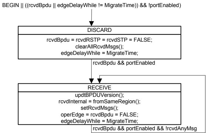
Figure 13-11—Port Receive state machine
13.29 Port Protocol Migration state machine
The specification of this state machine is identical to that of the Port Protocol Migration state machine for RSTP (Clause 17 of IEEE Std 802.1D).
13.30 Bridge Detection state machine
The specification of this state machine is identical to that of the Bridge Detection state machine for RSTP (17.25 of IEEE Std 802.1D).
13.31 Port Transmit state machine
The Port Transmit state machine shall implement the function specified by the state diagram contained in Figure 13-12 and the attendant definitions contained in 13.21 through 13.26.
This state machine is responsible for transmitting BPDUs.
NOTE 1—Any single received BPDU that changes the CIST Root Identifier, CIST External Root Path Cost, or CIST Regional Root associated with MSTIs should be processed in their entirety, or not at all, before encoding BPDUs for transmission. This recommendation is made to minimize the number of BPDUs to be transmitted following receipt of a BPDU carrying new information. It is not required for correctness and has not therefore been incorporated into the state machines.
NOTE 2—If a CIST state machine sets newInfo, this machine will ensure that a BPDU is transmitted conveying the new CIST information. If MST BPDUs can be transmitted through the port, this BPDU will also convey new MSTI information for all MSTIs. If a MSTI state machine sets newInfoMsti, and MST BPDUs can be transmitted through the port, this machine will ensure that a BPDU is transmitted conveying information for the CIST and all MSTIs. Separate newInfo and newInfoMsti variables are provided to avoid requiring useless transmission of a BPDU through a port that can only transmit STP BPDUs (as required by the Force Protocol Version parameter or Port Protocol Migration machine) following a change in MSTI information without any change to the CIST.
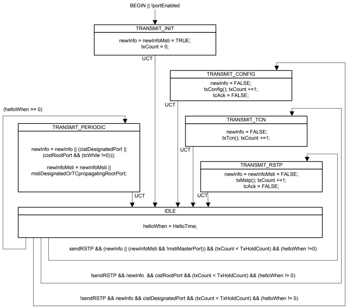
All transitions, except UCT, are qualified by "&& allTransmitReady".
Figure 13-12—Port Transmit state machine
13.32 Port Information state machine
The Port Information state machine for each tree shall implement the function specified by the state diagram contained in Figure 13-13 and the attendant definitions contained in 13.21 through 13.26.
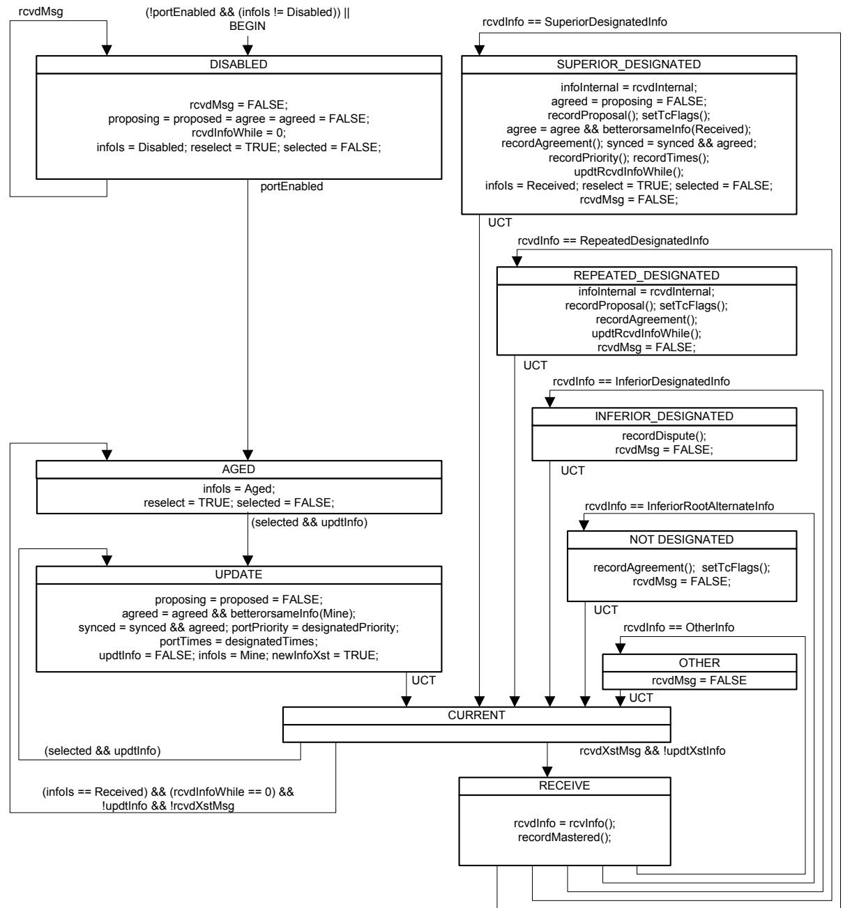
Figure 13-13—Port Information state machine
This state machine is responsible for recording the Spanning Tree information currently in use by the CIST or a given MSTI for a given Port, ageing that information out if it was derived from an incoming BPDU, and recording the origin of the information in the infoIs variable. The selected variable is cleared and reselect set to signal to the Port Role Selection machine that port roles need to be recomputed. The infoIs and portPriority variables from all ports are used in that computation and, together with portTimes, determine new values of designatedPriority and designatedTimes. The selected variable is set by the Port Role Selection machine once the computation is complete.
13.33 Port Role Selection state machine
The Port Role Selection state machine shall implement the function specified by the state diagram contained in Figure 13-14 and the attendant definitions contained in 13.21 through 13.26.
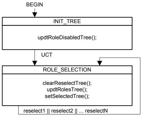
Figure 13-14—Port Role Selection state machine
13.34 Port Role Transitions state machine
The Port Role Transitions state machine shall implement the function specified by the state diagram contained in the following figures:
a) Part 1: Figure 13-15 for both the initialization of this state machine and the states associated with the DisabledPort role; and
b) Part 2: Figure 13-16 for the states associated with the MasterPort role; and
c) Part 3: Figure 13-17 for the states associated with the RootPort role; and
d) Part 4: Figure 13-18 for the states associated with the DesignatedPort role; and
e) Part 5: Figure 13-19 for the states associated with the AlternatePort and BackupPort roles;
and the attendant definitions contained in 13.21 through 13.26.
As Figure 13-15, Figure 13-16, Figure 13-17, Figure 13-18, and Figure 13-19 are component parts of the same state machine, the global transitions associated with these diagrams are possible exit transitions from the states shown in any of the diagrams.
Figure 13-15 and Figure 13-19 show the Port Roles for Ports that do not form part of the active topology of the given Tree.
Figure 13-16, Figure 13-17, and Figure 13-18 show the Port Roles that form part of the active topology.
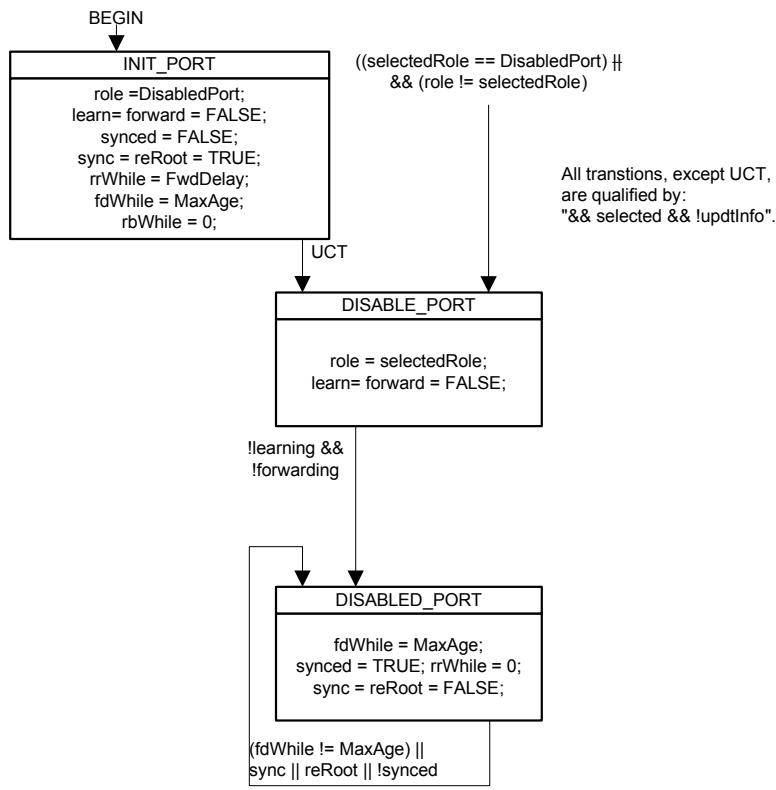
Figure 13-15—Disabled Port role transitions
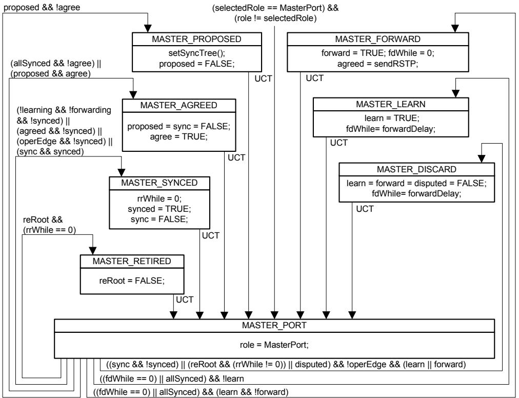
All transitions, except UCT, are qualified by "&& selected && !updtInfo".
Figure 13-16—Port Role Transitions state machine—MasterPort
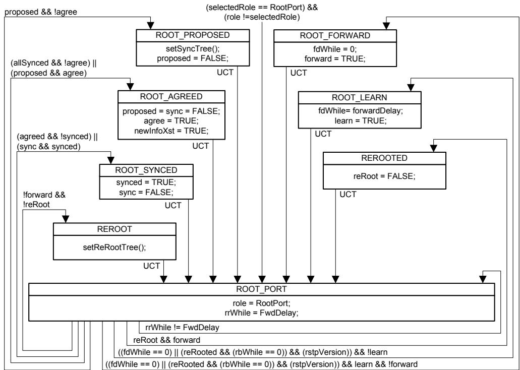
All transitions, except UCT, are qualified by "&& selected && !updtInfo".
Figure 13-17—Port Role Transitions state machine—RootPort
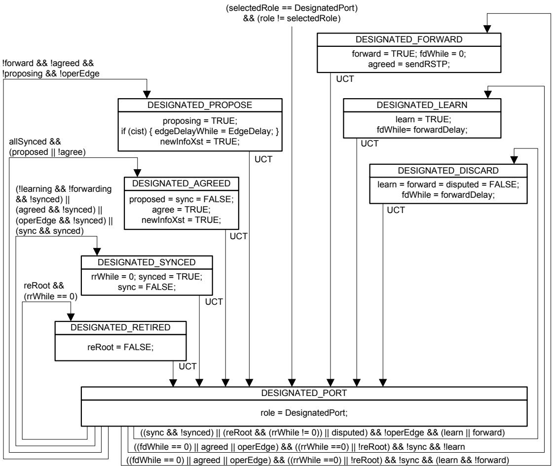
All transitions, except UCT, are qualified by "&& selected && !updtInfo".
Figure 13-18—Port Role Transitions state machine—DesignatedPort
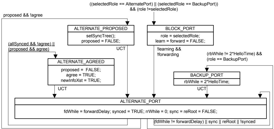
All transitions, except UCT, are qualified by "&& selected && !updtInfo".
Figure 13-19—Port Role Transitions state machine—AlternatePort and BackupPort
13.35 Port State Transition state machine
The Port State Transition state machine shall implement the function specified by the state diagram contained in Figure 13-20 and the attendant definitions contained in 13.21 through 13.26.
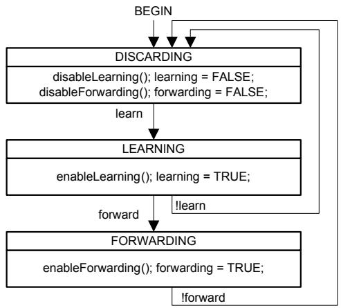
Figure 13-20—Port State Transition state machine
NOTE—A small system-dependent delay may occur on each of the transitions shown in the referenced state machine.
13.36 Topology Change state machine
The Topology Change state machine for each tree shall implement the function specified by the state diagram contained in Figure 13-21 and the attendant definitions contained in 13.21 through 13.26.
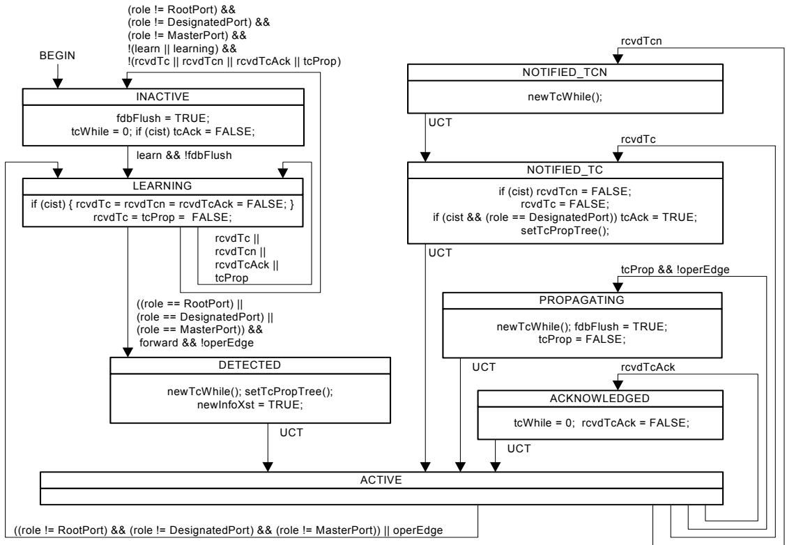
Figure 13-21—Topology Change state machine
13.37 Performance
This subclause places requirements on the setting of the parameters of MSTP. It recommends default operational values for performance parameters. These have been specified in order to avoid the need to set values prior to operation and have been chosen with a view to maximizing the ease with which network components interoperate.
The constraints on parameter values for correct operation are essentially the same as specified in IEEE Std 802.1D for RSTP, and provide for the integration of MST Bridges into LANs that contain Bridges using STP. Bridges using MSTP shall conform to the parameter value requirements of 17.14 of IEEE Std 802.1D. Implementations of MSTP and managers of Bridged Local Area Networks should note the recommendations of that Clause. Maximum, minimum, default, and applicable ranges are specified and recommended for values of the following parameters:
a) Maximum Bridge Diameter
b) Maximum Bridge Transit Delay
c) Maximum BPDU Transmission Delay
d) Maximum Message Age Increment Overestimate
e) Bridge Priority and Port Priority
f) External Port Path Cost (referred to as Port Path Cost in 17.14 of IEEE Std 802.1D)
g) Port Hello Time
NOTE—In MSTP Bridges, Hello Time is manageable on a per-Port basis, rather than per-Bridge in STP and RSTP. Port Hello Time, therefore, replaces the Bridge Hello Time parameter found in STP and RSTP.
h) Bridge Max Age
i) Bridge Forward Delay
This standard also makes recommendations on the applicable values of Internal Port Path Cost, a parameter specific to MSTP.
13.37.1 Internal Port Path Costs
It is recommended that default values of the Internal Port Path Cost parameter for each Bridge Port be based on the values shown in Table 13-3, the values being chosen according to the speed of the LAN segment to which each Port is attached.
Where intermediate link speeds are created as a result of the aggregation of two or more links of the same speed (see IEEE Std 802.3ad™ [B2]), it may be appropriate to modify the recommended values shown to reflect the change in link speed. However, as the primary purpose of the Path Cost is to establish the active topology of the network, it may be inappropriate for the Path Cost to track the effective speed of such links too closely, as the resultant active topology may differ from that intended by the network administrator. For example, if the network administrator had chosen an active topology that makes use of aggregated links for resilience (rather than for increased data rate), it would be inappropriate to cause a Spanning Tree topology change as a result of one of the physical links in an aggregation failing. Similarly, with links that can autonegotiate their data rate, reflecting such changes of data rate in changes to Path Cost may not be appropriate, depending on the intent of the network administrator. Hence, as a default behavior, such dynamic changes of data rate should not automatically cause changes in Path Cost for the Port concerned.
NOTE 1—The values shown apply to both full duplex and half duplex operation. The intent of the recommended values and ranges shown is to minimize the number of Bridges in which path costs need to be managed in order to exert control over the topology of the network.
NOTE 2—The values shown are the same as those recommended in IEEE Std 802.1D.
Table 13-3—Internal Port Path Costs
<table><tr><td>Parameter</td><td>Link Speed</td><td>Recommended value</td><td>Recommended range</td><td>Range</td></tr><tr><td rowspan="9">Internal Port Path Cost</td><td><=100 Kb/s</td><td>200 000 000</td><td>20 000 000 – 200 000 000</td><td>1 – 200 000 000</td></tr><tr><td>1 Mb/s</td><td>20 000 000</td><td>2 000 000 – 200 000 000</td><td>1 – 200 000 000</td></tr><tr><td>10 Mb/s</td><td>2 000 000</td><td>200 000 – 20 000 000</td><td>1 – 200 000 000</td></tr><tr><td>100 Mb/s</td><td>200 000</td><td>20 000 – 2 000 000</td><td>1 – 200 000 000</td></tr><tr><td>1 Gb/s</td><td>20 000</td><td>2 000 – 200 000</td><td>1 – 200 000 000</td></tr><tr><td>10 Gb/s</td><td>2 000</td><td>200 – 20 000</td><td>1 – 200 000 000</td></tr><tr><td>100 Gb/s</td><td>200</td><td>20 – 2 000</td><td>1 – 200 000 000</td></tr><tr><td>1 Tb/s</td><td>20</td><td>2 – 200</td><td>1 – 200 000 000</td></tr><tr><td>10 Tb/s</td><td>2</td><td>1 – 20</td><td>1 – 200 000 000</td></tr></table>
13.37.2 Port Hello Time
Port Hello Time takes the recommended default value given to Bridge Hello Time in 17.14 of IEEE Std 802.1D.
13.37.3 MaxHops
MaxHops (13.22.1) can be set by management to values in the range 6-40. The default value of MaxHops is 20.
14 Use of BPDUs by MSTP
This clause specifies the BPDU formats, encoding, and decoding used to exchange protocol parameters with other Bridges operating MSTP, RSTP, or STP, by a Bridge Protocol Entity operating MSTP (Clause 13).
14.1 BPDU Structure
14.1.1 Transmission and representation of octets
All BPDUs shall contain an integral number of octets. The octets in a BPDU are numbered starting from 1 and increasing in the order they are put into a Data Link Service Data Unit (DLSDU). When bit positions in an octet or a sequence of octets encode a number, the number is encoded as an unsigned binary numeral with bit positions in lower octet numbers having more significance. Within an octet, the bits are numbered from 8 to 1, where 1 is the low-order bit. Where sequences of bits are represented, higher order bits are shown to the left of lower order bits in the same octet, and bits in lower octet numbers are shown to the left of bits in higher octet numbers.
14.1.2 Components
A Protocol Identifier is encoded in the initial octets of all BPDUs. The single Protocol Identifier value of 0000 0000 0000 0000 identifies the Spanning Tree family of protocols (the Spanning Tree Algorithm and Protocol, the Rapid Spanning Tree Algorithm and Protocol, and the Multiple Spanning Tree Protocol).
14.2 Encoding of parameter types
The following parameter types are encoded as specified in 9.2 of IEEE Std 802.1D:
a) Protocol Identifiers
b) Protocol Version Identifiers
c) BPDU Types
d) Flags
e) Port Identifiers
f) Timer values
g) Length values
Additional considerations follow for encoding:
h) Port Roles
i) Bridge Identifiers
j) Port Identifiers
k) External Root Path Costs
1) Internal Root Path Costs
This standard specifies new or extended parameter types and encodings for
m) Hop Counts
14.2.1 Encoding of Port Role values
Port Role values shall be encoded in two consecutive flag bits, taken to represent an unsigned integer, as follows:
a) A value of 0 indicates Master Port;
b) A value of 1 indicates Alternate or Backup;
c) A value of 2 indicates Root;
d) A value of 3 indicates Designated.
14.2.2 Allocation and encoding of Bridge Identifiers
The 12-bit system ID extension component of a Bridge Identifier (9.2.5 of IEEE Std 802.1D) is used to allocate distinct Bridge Identifiers to each Spanning Tree instance supported by the operation of MSTP, based on the use of a single Bridge Address component value for the MST Bridge as a whole. The system ID extension value zero shall be allocated to the Bridge Identifier used by MSTP in support of the CIST; the system ID extension value allocated to the Bridge Identifier used by a given MSTI shall be equal to the MSTID.
NOTE 1—This convention is used to convey the MSTID for each MSTI parameter set in an MST BPDU.
The four most significant bits of the Bridge Identifier for a given Spanning Tree instance (the settable Priority component) can be modified independently of the other Bridge Identifiers supported by the Bridge, allowing full configuration control to be exerted over each Spanning Tree instance with regard to bridge priority.
NOTE 2—Only these four bits of the transmitting Bridge's Bridge Identifier are encoded in BPDUs for each MSTI. The remainder of the Bridge Identifier is derived from the CIST Bridge Identifier and the MSTID using the system ID extension convention described previously.
14.2.3 Allocation and encoding of Port Identifiers
The four most significant bits of the Port Identifier for a given Spanning Tree instance (the settable Priority component) can be modified independently for each Spanning Tree instance supported by the Bridge.
NOTE—Only these four bits of the transmitting Bridge's Port Identifier are encoded in a BPDU for each MSTI. The remainder of the Port Identifier is derived from the CIST Port Identifier.
14.2.4 Encoding of External Root Path Cost
The External Root Path Cost shall be encoded as specified by 9.2.6 of IEEE Std 802.1D for Root Path Cost in four octets, taken to represent a number of arbitrary cost units. Subclause 17.4 of IEEE Std 802.1D contains recommendations as to the increment to the Root Path Cost, in order that some common value can be placed on this parameter without requiring a management installation practice for Bridges in a network.
14.2.5 Encoding of Internal Root Path Cost
The Internal Root Path Cost shall be encoded in four octets, taken to represent a number of arbitrary cost units that may differ from those used for External Path Cost. Table 13-3 contains recommendations for the use of these units. These recommendations allow higher LAN speeds to be represented in support of both current and future technologies, while still allowing common values to be assigned without a management installation practice.
NOTE—This revision from the original IEEE Std 802.1D recommendations for STP Path Cost causes no operational difficulties because there was no installed base of Bridges using the Internal Root Path Cost parameter prior to approval of this standard.
14.2.6 Encoding of Hop Counts
The number of remaining Hops parameter shall be encoded in a single octet.
14.3 BPDU formats and parameters
14.3.1 STP BPDUs
The formats of STP BPDU Configuration and TCN BPDUs are as specified in Clause 9 of IEEE Std 802.1D.
14.3.2 RST BPDUs
The format of RST BPDUs is as specified in Clause 9 of IEEE Std 802.1D.
14.3.3 MST BPDUs
The format of MST BPDUs is compatible with that specified for RST BPDUs (Clause 9 of IEEE Std 802.1D), with the addition of fields to convey information for the IST and each MSTI and is shown in Figure 14-1. Each transmitted MST BPDU shall contain the parameters specified and no others.
NOTE—The BPDU specified in this clause is carried in an LLC Type 1 frame following the DSAP, LSAP, and UI fields (7.12 on Addressing in IEEE Std 802.1D). The consequence of the inclusion of those three octets in an IEEE 802.3 or Ethernet MAC frame is that, if the MAC Addresses in the frame are aligned on an even octet boundary, then so are the BPDU octet pairs 6 and 7, 14 and 15, 18 and 19, etc.
<table><tr><td></td><td>Octet</td></tr><tr><td>Protocol Identifier</td><td>1-2</td></tr><tr><td>Protocol Version Identifier</td><td>3</td></tr><tr><td>BPDU Type</td><td>4</td></tr><tr><td>CIST Flags</td><td>5</td></tr><tr><td>CIST Root Identifier</td><td>6-13</td></tr><tr><td>CIST External Path Cost</td><td>14-17</td></tr><tr><td>CIST Regional Root Identifier</td><td>18-25</td></tr><tr><td>CIST Port Identifier</td><td>26-27</td></tr><tr><td>Message Age</td><td>28-29</td></tr><tr><td>Max Age</td><td>30-31</td></tr><tr><td>Hello Time</td><td>32-33</td></tr><tr><td>Forward Delay</td><td>34-35</td></tr><tr><td>Version 1 Length = 0</td><td>36</td></tr><tr><td>Version 3 Length</td><td>37-38</td></tr><tr><td>MST Configuration Identifier</td><td>39-89</td></tr><tr><td>CIST Internal Root Path Cost</td><td>90-93</td></tr><tr><td>CIST Bridge Identifier</td><td>94-101</td></tr><tr><td>CIST Remaining Hops</td><td>102</td></tr><tr><td>MSTI Configuration Messages (may be absent)</td><td>103-39 + Version 3 Length</td></tr></table>
Figure 14-1—MST BPDU parameters and format
14.4 Validation of received BPDUs
An MST Bridge Protocol Entity shall examine Octets 1 and 2 (conveying the Protocol Identifier), Octet 3 (conveying the Protocol Version Identifier encoded as a number), Octet 4 (conveying the BPDU Type), and the total length of the received BPDU (including the preceding fields, but none prior to the Protocol Identifier) to determine the further processing required as follows:
a) If the Protocol Identifier is 0000 0000 0000 0000, the BPDU Type is 0000 0000, and the BPDU contains 35 or more octets, it shall be decoded as an STP Configuration BPDU.
b) If the Protocol Identifier is 0000 0000 0000 0000, the BPDU Type is 1000 0000 (where bit 8 is shown at the left of the sequence), and the BPDU contains 4 or more octets, it shall be decoded as an STP TCN BPDU (9.3.2 of IEEE Std 802.1D).
c) If the Protocol Identifier is 0000 0000 0000 0000, the Protocol Version Identifier is 2, and the BPDU Type is 0000 0010 (where bit 8 is shown at the left of the sequence), and the BPDU contains 36 or more octets, it shall be decoded as an RST BPDU.
d) If the Protocol Identifier is 0000 0000 0000 0000, the Protocol Version Identifier is 3 or greater, and the BPDU Type is 0000 0010, and the BPDU:
1) Contains 35 or more but less than 103 octets; or
2) Contains a Version 1 Length that is not 0; or
3) Contains a Version 3 length that does not represent an integral number, from 0 to 64 inclusive, of MSTI Configuration Messages;
it shall be decoded as an RST BPDU.
e) If the Protocol Identifier is 0000 0000 0000 0000, the Protocol Version Identifier is 3 or greater, and the BPDU Type is 0000 0010, and the BPDU contains:
1) 102 or more octets; and
2) A Version 1 Length of 0; and
3) A Version 3 length representing an integral number, from 0 to 64 inclusive, of MSTI Configuration Messages;
it shall be decoded as an MST BPDU.
f) Otherwise the BPDU shall be discarded and not processed.
NOTE 1—The LLC LSAP that identifies BPDUs is reserved for standard protocols; no other protocols using that LSAP have been standardized although they may be at some future time. At that time, BPDUs with different Protocol Identifiers may be processed according to the rules of those protocols but will still be discarded from the point of view of MSTP.
NOTE 2—These validation rules are in accord with the approach to backward compatibility of future version enhancements set out in 9.3.4 of IEEE Std 802.1D. Test a) and test b) do not check the Protocol Version Identifier.
NOTE 3—These validation rules do not contain a loopback check of the form specified in 9.3.4 of IEEE Std 802.1D.
14.5 Transmission of BPDUs
An MST Bridge Protocol Entity shall encode 0000 0000 0000 0000 in Octets 1 and 2 (conveying the Protocol Identifier), the remaining fields shall be encoded to convey an STP Configuration BPDU, an STP TCN BPDU, an RST BPDU, or an MST BDU as required by the Force Protocol Version parameter, the Port Protocol Migration state machine, and other protocol parameters, all as specified in Clause 13.
a) If transmission of an STP Configuration BPDU is required, the Protocol Version Identifier shall be 0, and the BPDU Type shall be 0000 0000.
b) If transmission of an STP TCN BPDU is required, the Protocol Version Identifier shall be 0, and the BPDU Type shall be 1000 0000.
c) If transmission of an RST BPDU is required, the Protocol Version Identifier shall be 2, and the BPDU Type shall be 0000 0010.
d) If transmission of an MST BPDU is required, the Protocol Version Identifier shall be 3, and the BPDU Type shall be 0000 0010.
The remaining parameters for STP Configuration, RST, and MST BPDUs shall be encoded as follows.
14.6 Encoding and decoding of STP Configuration, RST, and MST BPDUs
STP Configuration, RST, and MST BPDU protocol parameters are encoded for transmission, and decoded, checked, or ignored on receipt as follows:
a) Bit 1 of Octet 5 conveys the CIST Topology Change flag.
b) Bit 2 of Octet 5 conveys the CIST Proposal flag in RST and MST BPDUs. It is unused in STP Configuration BPDUs and shall be transmitted as 0 and ignored on receipt.
c) Bits 3 and 4 of Octet 5 conveys the CIST Port Role in RST and MST BPDUs. It is unused in STP Configuration BPDUs and shall be transmitted as 0 and ignored on receipt.
d) Bit 5 of Octet 5 conveys the CIST Learning flag in RST and MST BPDUs. It is unused in STP Configuration BPDUs and shall be transmitted as 0 and ignored on receipt.
e) Bit 6 of Octet 5 conveys the CIST Forwarding flag in RST and MST BPDUs. It is unused in STP Configuration BPDUs and shall be transmitted as 0 and ignored on receipt.
f) Bit 7 of Octet 5 conveys the CIST Agreement flag in RST and MST BPDUs. It is unused in STP Configuration BPDUs and shall be transmitted as 0 and ignored on receipt.
g) Bit 8 of Octet 5 conveys the Topology Change Acknowledge Flag in STP Configuration BPDUs. It is unused in RST and MST BPDUs and shall be transmitted as 0 and ignored on receipt.
h) Octets 6 through 13 convey the CIST Root Identifier.
NOTE 1—The 12-bit system id extension component of the CIST Root Identifier can be received and subsequently transmitted as an arbitrary value, even in MST BPDUs, since the CIST Root may be an STP Bridge.
i) Octets 14 through 17 convey the CIST External Root Path Cost.
j) Octets 18 through 25 shall take the value of the CIST Regional Root Identifier when transmitted in RST and MST BPDUs, and the value of the CIST Bridge Identifier of the transmitting Bridge when transmitted in STP Configuration BPDUs. On receipt of an STP Configuration or RST BPDU, both the CIST Regional Root Identifier and the CIST Designated Bridge Identifier shall be decoded from this field. On receipt of an MST BPDU, the CIST Regional Root Identifier shall be decoded from this field.
k) Octets 26 and 27 convey the CIST Port Identifier of the transmitting Bridge Port.
1) Octets 28 and 29 convey the Message Age timer value.
m) Octets 30 and 31 convey the Max Age timer value.
n) Octets 32 and 33 convey the Hello Time timer value used by the transmitting Bridge Port.
o) Octets 34 and 35 convey the Max Age timer value.
No further octets shall be encoded in STP Configuration BPDUs. Additional octets in received BPDUs identified by the validation procedure (14.4) as STP Configuration BPDUs shall be ignored. The specification of encoding or decoding of further octets in this subclause refers only to RST and MST BPDUs.
p) Octet 36 conveys the Version 1 Length. This shall be transmitted as 0. It is checked on receipt by the validation procedure (14.4).
No further octets shall be encoded in RST BPDUs. Additional octets in received BPDUs identified by the validation procedure (14.4) as RST BPDUs shall be ignored. The specification of encoding or decoding of further octets in this subclause refers only to MST BPDUs.
NOTE 2—As Version 2 does not specify any additional fields beyond the end of the Version 0 information, there is no Version 2 Length field specified in Version 2 of the protocol (see Clause 9 of IEEE Std 802.1D) and, therefore, no need for a Version 2 length field here.
q) Octets 37 and 38 convey the Version 3 Length. Its value is the number of octets taken by the parameters that follow in the BPDU. It is checked on receipt by the validation procedure (14.4).
r) Octets 39 through 89 convey the elements of the MST Configuration Identifier (13.7):
1) The Configuration Identifier Format Selector is encoded in Octet 39 and shall take the value 0000 0000;
2) The Configuration Name is encoded in octets 40 through 71;
3) The Revision Level is encoded as a number in octets 72 through 73;
4) The Configuration Digest is encoded in octets 74 through 89.
s) Octets 90 through 93 convey the CIST Internal Root Path Cost.
t) Octets 94 through 101 convey the CIST Bridge Identifier of the transmitting Bridge. The 12-bit system id extension component of the CIST Bridge Identifier shall be transmitted as 0. The behavior on receipt is unspecified if it is non-zero.
NOTE 3—The four most significant bits of the Bridge Identifier constitute the manageable priority component for each MSTI and are separately encoded in MSTI Configuration Messages in the BPDU.
NOTE 4—The four most significant bits constitute the manageable priority component of each MSTI and are separately encoded in MSTI Configuration Messages in the BPDU.
u) Octet 102 encodes the value of remaining Hops for the CIST.
v) A sequence of zero or more, up to a maximum of 64, MSTI Configuration Messages follows, each encoded as specified in 14.6.1.
14.6.1 MSTI Configuration Messages
A single instance of the following set of parameters is encoded for each MSTI supported by the transmitting Bridge.
a) Bits 1, 2, 3 and 4, 5, 6, 7, and 8, respectively, of Octet 1 convey the Topology Change flag, Proposal flag, Port Role, Learning flag, Forwarding flag, Agreement flag, and Master flag for this MSTI.
b) Octets 2 through 9 convey the Regional Root Identifier (13.24.2) as illustrated in Figure 14-2. This includes the value of the MSTID for this Configuration Message encoded in bits 4 through 1 of Octet 1, and bits 8 through 1 of Octet 2.
NOTE—The four most significant bits of each MSTI's Regional Root Identifier constitute a manageable priority component.
c) Octets 10 through 13 convey the Internal Root Path Cost.
d) Bits 5 through 8 of Octet 14 convey the value of the Bridge Identifier Priority for this MSTI. Bits 1 through 4 of Octet 14 shall be transmitted as 0, and ignored on receipt.
e) Bits 5 through 8 of Octet 15 convey the value of the Port Identifier Priority for this MSTI. Bits 1 through 4 of Octet 15 shall be transmitted as 0, and ignored on receipt.
f) Octet 16 conveys the value of remainingHops for this MSTI (13.24.3).
Octet
<table><tr><td>MSTI Flags</td><td>1</td></tr><tr><td>MSTI Regional Root Identifier</td><td>2–9</td></tr><tr><td>MSTI Internal Root Path Cost</td><td>10–13</td></tr><tr><td>MSTI Bridge Priority</td><td>14</td></tr><tr><td>MSTI Port Priority</td><td>15</td></tr><tr><td>MSTI Remaining Hops</td><td>16</td></tr></table>
Figure 14-2—MSTI Configuration Message parameters and format
Annex A
(normative)
PICS proforma $^{20}$
A.1 Introduction
The supplier of a protocol implementation which is claimed to conform to this standard shall complete the following Protocol Implementation Conformance Statement (PICS) proforma.
A completed PICS proforma is the PICS for the implementation in question. The PICS is a statement of which capabilities and options of the protocol have been implemented. The PICS can have a number of uses, including use
a) By the protocol implementer, as a checklist to reduce the risk of failure to conform to the standard through oversight;
b) By the supplier and acquirer—or potential acquirer—of the implementation, as a detailed indication of the capabilities of the implementation, stated relative to the common basis for understanding provided by the standard PICS proforma;
c) By the user—or potential user—of the implementation, as a basis for initially checking the possibility of interworking with another implementation (note that, while interworking can never be guaranteed, failure to interwork can often be predicted from incompatible PICSs);
d) By a protocol tester, as the basis for selecting appropriate tests against which to assess the claim for conformance of the implementation.
A.2 Abbreviations and special symbols
A.2.1 Status symbols
<table><tr><td>M</td><td>mandatory</td></tr><tr><td>O</td><td>optional</td></tr><tr><td>O.n</td><td>optional, but support of at least one of the group of options labeled by the same numeral n is required</td></tr><tr><td>X</td><td>prohibited</td></tr><tr><td>pred:</td><td>conditional-item symbol, including predicate identification: see A.3.4</td></tr><tr><td><eq>\neg</eq></td><td>logical negation, applied to a conditional item’s predicate</td></tr></table>
A.2.2 General abbreviations
N/A not applicable
PICS Protocol Implementation Conformance Statement
A.3 Instructions for completing the PICS proforma
A.3.1 General structure of the PICS proforma
The first part of the PICS proforma, implementation identification and protocol summary, is to be completed as indicated with the information necessary to identify fully both the supplier and the implementation.
The main part of the PICS proforma is a fixed-format questionnaire, divided into several subclauses, each containing a number of individual items. Answers to the questionnaire items are to be provided in the rightmost column, either by simply marking an answer to indicate a restricted choice (usually Yes or No) or by entering a value or a set or range of values. (Note that there are some items where two or more choices from a set of possible answers can apply; all relevant choices are to be marked.)
Each item is identified by an item reference in the first column. The second column contains the question to be answered; the third column records the status of the item—whether support is mandatory, optional, or conditional: see also A.3.4. The fourth column contains the reference or references to the material that specifies the item in the main body of this standard, and the fifth column provides the space for the answers.
A supplier may also provide (or be required to provide) further information, categorized as either Additional Information or Exception Information. When present, each kind of further information is to be provided in a further subclause of items labeled $Ai$ or $Xi$ , respectively, for cross-referencing purposes, where $i$ is any unambiguous identification for the item (e.g., simply a numeral). There are no other restrictions on its format and presentation.
A completed PICS proforma, including any Additional Information and Exception Information, is the Protocol Implementation Conformation Statement for the implementation in question.
NOTE—Where an implementation is capable of being configured in more than one way, a single PICS may be able to describe all such configurations. However, the supplier has the choice of providing more than one PICS, each covering some subset of the implementation's configuration capabilities, in case that makes for easier and clearer presentation of the information.
A.3.2 Additional information
Items of Additional Information allow a supplier to provide further information intended to assist the interpretation of the PICS. It is not intended or expected that a large quantity will be supplied, and a PICS can be considered complete without any such information. Examples might be an outline of the ways in which a (single) implementation can be set up to operate in a variety of environments and configurations, or information about aspects of the implementation that are outside the scope of this standard but that have a bearing on the answers to some items.
References to items of Additional Information may be entered next to any answer in the questionnaire and may be included in items of Exception Information.
A.3.3 Exception information
It may occasionally happen that a supplier will wish to answer an item with mandatory status (after any conditions have been applied) in a way that conflicts with the indicated requirement. No pre-printed answer will be found in the Support column for this item. Instead, the supplier shall write the missing answer into the Support column, together with an Xi reference to an item of Exception Information, and shall provide the appropriate rationale in the Exception item itself.
An implementation for which an Exception item is required in this way does not conform to this standard.
NOTE—A possible reason for the situation described previously is that a defect in this standard has been reported, a correction for which is expected to change the requirement not met by the implementation.
A.3.4 Conditional status
A.3.4.1 Conditional items
The PICS proforma contains a number of conditional items. These are items for which both the applicability of the item itself, and its status if it does apply—mandatory or optional—are dependent on whether certain other items are supported.
Where a group of items is subject to the same condition for applicability, a separate preliminary question about the condition appears at the head of the group, with an instruction to skip to a later point in the questionnaire if the “Not Applicable” answer is selected. Otherwise, individual conditional items are indicated by a conditional symbol in the Status column.
A conditional symbol is of the form “pred: S” where pred is a predicate as described in A.3.4.2 below, and S is a status symbol, M or 0.
If the value of the predicate is true (see A.3.4.2), the conditional item is applicable, and its status is indicated by the status symbol following the predicate: The answer column is to be marked in the usual way. If the value of the predicate is false, the “Not Applicable” (N/A) answer is to be marked.
A.3.4.2 Predicates
A predicate is one of the following:
a) An item-reference for an item in the PICS proforma: The value of the predicate is true if the item is marked as supported and is false otherwise;
b) A predicate-name, for a predicate defined as a boolean expression constructed by combining item-references using the boolean operator OR: The value of the predicate is true if one or more of the items is marked as supported;
c) The logical negation symbol “ $\neg$ ” prefixed to an item-reference or predicate-name: The value of the predicate is true if the value of the predicate formed by omitting the “ $\neg$ ” symbol is false, and vice versa.
Each item whose reference is used in a predicate or predicate definition, or in a preliminary question for grouped conditional items, is indicated by an asterisk in the Item column.
A.3.4.3 References to the text of IEEE Std 802.1D
Many tables in the PICS Proforma refer to the text of IEEE Std 802.1D (ANSI/IEEE Std 802.1D). A short form reference, of the form $\{D\}X$ , is used in the “References” columns of these tables to denote references to clauses, subclauses, or tables in IEEE Std 802.1D, where X is the clause, subclause, or table identifier.
A.4 PICS proforma for IEEE Std 802.1Q
A.4.1 Implementation identification
<table><tr><td>Supplier</td><td></td></tr><tr><td>Contact point for queries about the PICS</td><td></td></tr><tr><td>Implementation Name(s) and Version(s)</td><td></td></tr><tr><td>Other information necessary for full identification, e.g., name(s) and version(s) of machines and/or operating system names</td><td></td></tr></table>
NOTE 1—Only the first three items are required for all implementations; other information may be completed as appropriate in meeting the requirement for full identification.
NOTE 2—The terms “Name” and “Version” should be interpreted appropriately to correspond with a supplier’s terminology (e.g., Type, Series, Model).
A.4.2 Protocol summary, IEEE Std 802.1Q
<table><tr><td>Identification of protocol specification</td><td colspan="3">IEEE Std 802.1Q-2005, IEEE Standards for Local and metropolitan area networks—Virtual Bridged Local Area Networks</td></tr><tr><td rowspan="2">Identification of amendments and corrigenda to the PICS proforma which have been completed as part of the PICS</td><td colspan="3">Amd. : Corr. :</td></tr><tr><td colspan="3">Amd. : Corr. :</td></tr><tr><td>Have any Exception items been required?(See A.3.3: the answer “Yes” means that the implementation does not conform to IEEE Std 802.1Q)</td><td colspan="3">No [ ] Yes [ ]</td></tr></table>
<table><tr><td>Date of Statement</td><td></td></tr></table>
A.5 Major capabilities
<table><tr><td>Item</td><td>Feature</td><td>Status</td><td>References</td><td>Support</td></tr><tr><td>MAC</td><td>Do the implementations of MAC Technologies and support of the MAC Internal Sublayer Service conform to MAC standards as specified in 6.4 and 6.5?(If support of a specific MAC technology is claimed, any PICS Proforma(s) required by the Standard specifying that technology shall also be completed.)</td><td>M</td><td>A.6{D}6.4, {D}6.5.</td><td>Yes [ ]</td></tr><tr><td>LLC</td><td>Is a class of LLC supporting Type 1 operations supported on all Bridge Ports in conformance with IEEE Std 802.2? (The PICS Proforma required by IEEE Std 802.2 shall also be completed.)</td><td>M</td><td>8.2, 8.3, 8.13, {D}7.2, {D}7.3, {D}7.12.IEEE Std 802.2</td><td>Yes [ ]</td></tr><tr><td>RLY</td><td>Does the implementation relay and filter frames as specified?</td><td>M</td><td>8.5, 8.6, 8.7, 6.8, 8.8, A.7{D}7.1, {D}7.5, {D}7.6, {D}7.7.</td><td>Yes [ ]</td></tr><tr><td>BFS</td><td>Does the implementation maintain the information required to make frame filtering decisions and support Basic Filtering Services?</td><td>M</td><td>A.8{D}7.1, {D}7.5, {D}7.8, {D}7.9.</td><td>Yes [ ]</td></tr><tr><td>ADDR</td><td>Does the implementation conform to the provisions for addressing?</td><td>M</td><td>A.9{D}7.12</td><td>Yes [ ]</td></tr><tr><td>RSTP</td><td>Is the Rapid Spanning Tree Protocol implemented?</td><td>O.1</td><td>5, A.10, {D}9, {D}17</td><td>Yes [ ]</td></tr><tr><td>BPDU</td><td>Are transmitted BPDUs encoded and received BPDUs validated as specified?</td><td>M</td><td>A.11{D}9, {D}17.21.19, {D}17.21.20, {D}17.21.21.</td><td>Yes [ ]</td></tr><tr><td>IMP</td><td>Are the required implementation parameters included in this completed PICS?</td><td>M</td><td>A.12{D}7.9</td><td>Yes [ ]</td></tr><tr><td>PERF</td><td>Are the required performance parameters included in this completed PICS?(Operation of the Bridge within the specified parameters shall not violate any of the other conformance provisions of this standard.)</td><td>M</td><td>A.13{D}16</td><td>Yes [ ]</td></tr><tr><td>MGT</td><td>Is management of the Bridge supported?</td><td>O</td><td>A.14{D}14</td><td>Yes [ ] No [ ]</td></tr><tr><td>RMGT</td><td>Is a remote management protocol supported?</td><td>MGT:O</td><td>A.15{D}5.2</td><td>Yes [ ] No [ ]</td></tr><tr><td>TC</td><td>Are multiple Traffic Classes supported for relaying frames?</td><td>O</td><td>A.16{D}7.7.3, {D}7.7.4.</td><td>Yes [ ] No [ ]</td></tr><tr><td>EFS</td><td>Are Extended Filtering Services supported for relaying and filtering frames?</td><td>O</td><td>A.17{D}7.12</td><td>Yes [ ] No [ ]</td></tr><tr><td>GMRP</td><td>Is the GARP Multicast Registration Protocol (GMRP) implemented?</td><td>EFS:M</td><td>A.18{D}10</td><td>Yes [ ] N/A[ ]</td></tr><tr><td>GARP</td><td>Is the Generic Attribute Registration Protocol (GARP) implemented in support of the GMRP Application?</td><td>M</td><td>{D}12A.19</td><td>Yes [ ]</td></tr><tr><td>VLAN</td><td>Does the implementation support the ability to insert tag headers into, modify tag headers in, and remove tag headers from relayed frames?</td><td>M</td><td>5.3, 6.1, 6.6, 6.7, 8.6, 6.8, 9</td><td>Yes [ ]</td></tr><tr><td>GVRP</td><td>Does the implementation support the ability to perform automatic configuration and management of VLAN topology information by means of GVRP on all Ports?</td><td>M</td><td>5.3, 11, A.22</td><td>Yes [ ]</td></tr><tr><td>MSTP</td><td>Is the Multiple Spanning Tree protocol implemented?</td><td>O.1</td><td>5, 7, 8.4, 8.6.1, 8.8.7, 8.9, 8.10, 8.13.7, 11.2.3.4, 11.3.1, 13, 14, A.20</td><td>Yes [ ] No [ ]</td></tr><tr><td>VMGT</td><td>Does the implementation support VLAN management operations?</td><td>MGT:O</td><td>5.3.1, 12.10.2, 12.10.3</td><td>Yes [ ] No [ ]</td></tr></table>
A.6 Media Access Control methods
<table><tr><td>Item</td><td>Feature</td><td>Status</td><td>References</td><td>Support</td></tr><tr><td></td><td>Which Media Access Control methods are implemented in conformance with the relevant MAC Standards?</td><td></td><td>5.3, 6.4, 6.5,{D}6.4, {D}6.5</td><td></td></tr><tr><td>MAC-802.3</td><td>CSMA/CD, IEEE Std 802.3</td><td>O.2</td><td></td><td>Yes [ ] No [ ]</td></tr><tr><td>MAC-802.5</td><td>Token Ring, IEEE Std 802.5</td><td>O.2</td><td></td><td>Yes [ ] No [ ]</td></tr><tr><td>MAC-9314-2</td><td>FDDI, ISO 9314-2</td><td>O.2</td><td></td><td>Yes [ ] No [ ]</td></tr><tr><td>MAC-802.11</td><td>Wireless LAN, IEEE Std 802.11</td><td>O.2</td><td></td><td>Yes [ ] No [ ]</td></tr><tr><td>MAC-1</td><td>Has a PICS been completed for each of the Media Access Control methods implemented as required by the relevant MAC Standards?</td><td>M</td><td></td><td>Yes[ ]</td></tr><tr><td>MAC-2</td><td>Do all the Media Access Control methods implemented support the MAC Internal Sublayer Service as specified.</td><td>M</td><td>6.4, 6.5, {D}6.4,{D}6.5</td><td>Yes [ ]</td></tr><tr><td>MAC-3</td><td>Are the adminPointToPointMAC and operPointToPointMAC parameters implemented on all Ports?</td><td>M</td><td>6.4, 6.5, {D}6.4,{D}6.5</td><td>Yes [ ]</td></tr><tr><td>MAC-4</td><td>Does the implementation support the use of the adminEdgePort and operEdgePort parameters on any Ports?</td><td>O</td><td>6.4, 6.5, {D}6.4.2</td><td>Yes [ ] No [ ]</td></tr><tr><td>MAC-4a</td><td>State which Bridge Ports support the adminEdgePort and operEdgePort parameters</td><td></td><td></td><td>Ports____</td></tr><tr><td>MAC-5</td><td>Is the priority of received frames set to the Default Priority where specified for the MAC?</td><td>M</td><td>6.5, {D}6.5.1,{D}6.5.4</td><td>Yes[ ]</td></tr><tr><td>MAC-6</td><td>Can the Default Priority be set for each Port</td><td>O</td><td>6.5, {D}6.5.1,{D}6.5.4</td><td>Yes [ ] No [ ]</td></tr><tr><td>MAC-7</td><td>Can the Default Priority be set to any of 0–7?</td><td>MAC-6:M</td><td>6.5, {D}6.5.1,{D}6.5.4</td><td>Yes[ ]</td></tr><tr><td>MAC-8</td><td>Is an M_UNITDATA.indication generated by the FDDI MAC entity for a Port on receipt of frame transmitted by that entity?</td><td>FDDI:X</td><td>6.5, {D}6.5.3,ISO 9314-2</td><td>No [ ]N/A[ ]</td></tr><tr><td>MAC-9</td><td>Is only Asynchronous service used on FDDI rings?</td><td>FDDI:M</td><td>ISO 9314-2Clause 8.1.4</td><td>Yes [ ]N/A[ ]</td></tr><tr><td>MAC-10</td><td>Is the C indicator set on receipt of a frame for forwarding from an FDDI ring?</td><td>FDDI:O.2</td><td>6.5, {D}6.5.3,ISO 9314-2,Clause 7.3.8</td><td>Yes [ ] No [ ]N/A[ ]</td></tr><tr><td>MAC-11</td><td>Is the C indicator unaltered on receipt of a frame for forwarding from an FDDI ring?</td><td>FDDI:O.2</td><td>6.5, {D}6.5.3,ISO 9314-2,Clause 7.3.8</td><td>Yes [ ] No [ ]N/A[ ]</td></tr><tr><td>MAC-12</td><td>Is the minimum tagged frame length that can be transmitted on IEEE Std 802.3 Ports less than 68 (but 64 or more) octets?</td><td>MAC-802.3:O</td><td>6.5.1</td><td>Yes [ ] No [ ]N/A [ ]</td></tr><tr><td>MAC-13</td><td>When transmitting untagged frames and the canonical_format_indicator parameter indicates that the mac_service_data_unit may contain embedded MAC Addresses in a format inappropriate to the destination MAC method, which of the following procedures is adopted by the Bridge:Convert any embedded MAC Addresses in the mac_service_data_unit to the format appropriate to the destination MAC method.</td><td>O.2</td><td></td><td>Yes [ ] No [ ]</td></tr><tr><td>MAC-14</td><td>Discard the frame without transmission on that Port.</td><td>O.2</td><td></td><td>Yes [ ] No [ ]</td></tr></table>
Predicates:
FDDI = MAC-9314-2[Yes]
A.7 Relay and filtering of frames
<table><tr><td>Item</td><td>Feature</td><td>Status</td><td>References</td><td>Support</td></tr><tr><td>RLY-1</td><td>Are received frames with MAC method errors discarded?</td><td>M</td><td>{D}6.4, 8.5</td><td>Yes [ ]</td></tr><tr><td>RLY-2</td><td>Are user data frames the only type of frame relayed?</td><td>M</td><td>8.5</td><td>Yes [ ]</td></tr><tr><td>RLY-3</td><td>Is the priority of each frame relayed regenerated as specified?</td><td>M</td><td>6.5, 6.7.3, 8.5</td><td>Yes [ ]</td></tr><tr><td>RLY-4</td><td>Are the default values of the Priority Regeneration Table as specified for each Port?</td><td>M</td><td>6.7.3, Table 6</td><td>Yes [ ]</td></tr><tr><td>RLY-5</td><td>Can the Priority Regeneration Table be modified?</td><td>O</td><td>6.7.3, Table 6</td><td>Yes [ ]</td></tr><tr><td>RLY-6</td><td>Can the entries in the Priority Regeneration Table be set independently for each priority and Port and to any of the full range of values?</td><td>RLY-5: M</td><td>6.7.3, Table 6</td><td>Yes [ ]</td></tr><tr><td>RLY-7</td><td>Are frames transmitted by an LLC User attached at a Bridge Port also submitted for relay?</td><td>M</td><td>8.5</td><td>Yes [ ]</td></tr><tr><td>RLY-8</td><td>Are correctly received user data frames relayed subject to the conditions imposed by the Forwarding Process?</td><td>M</td><td>8.6, 8.6.2, 8.6.1, 8.6.3, 8.6.5, 8.6.4, 8.8, Table 8-4, Table 8-5, Table 8-6</td><td>Yes [ ]</td></tr><tr><td>RLY-9</td><td>Is the order of relayed frames preserved as required by the forwarding process?</td><td>M</td><td>8.6.6</td><td>Yes [ ]</td></tr><tr><td>RLY-10</td><td>Is a relayed frame submitted to a MAC Entity for transmission only once?</td><td>M</td><td>8.6.7</td><td>Yes [ ]</td></tr><tr><td>RLY-11</td><td>Is a maximum bridge transit delay enforced for relayed frames?</td><td>M</td><td>8.6.7</td><td>Yes [ ]</td></tr><tr><td>RLY-12</td><td>Are queued frames discarded if a Port leaves the Forwarding State?</td><td>M</td><td>8.6.7</td><td>Yes [ ]</td></tr><tr><td>RLY-13</td><td>Is the default algorithm for selecting frames for transmission supported?</td><td>M</td><td>8.6.8</td><td>Yes [ ]</td></tr><tr><td>RLY-14</td><td>Is the access priority of each transmitted frame as specified for each media access method?</td><td>M</td><td>6.3.9</td><td>Yes [ ]</td></tr><tr><td>RLY-15</td><td>Is the FCS of frames relayed between Ports of the same MAC type preserved?</td><td>O</td><td>6.7</td><td>Yes [ ] No [ ]</td></tr><tr><td>RLY-16</td><td>Is the undetected frame error rate greater than that achievable by preserving the FCS?</td><td><eq>\neg</eq>RLY-15:X</td><td>6.3.7, 6.7</td><td>No [ ] N/A [ ]</td></tr></table>
A.8 Basic Filtering Services
<table><tr><td>Item</td><td>Feature</td><td>Status</td><td>References</td><td>Support</td></tr><tr><td>BFS-1</td><td>Are correctly received user data frames submitted to the Learning Process?</td><td>M</td><td>8.6, 8.7</td><td>Yes [ ]</td></tr><tr><td>BFS-2</td><td>Are correctly received frames of types other than user data frames submitted to the Learning Process?</td><td>O</td><td>8.6, 8.7</td><td>Yes [ ] No [ ]</td></tr><tr><td>BFS-3</td><td>Does the Filtering Database support creation and update of Dynamic Filtering Entries by the Learning Process?</td><td>M</td><td>8.7, 8.8, 8.8.3</td><td>Yes [ ]</td></tr><tr><td>BFS-4</td><td>Are Dynamic Filtering Entries created and updated if and only if the Port State permits?</td><td>M</td><td>8.7, 8.8.3</td><td>Yes [ ]</td></tr><tr><td>BFS-5</td><td>Are Dynamic Filtering Entries created on receipt of frames with a group source address?</td><td>X</td><td>8.7, 8.8.3</td><td>No [ ]</td></tr><tr><td>BFS-6</td><td>Can a Dynamic Filtering Entry be created that conflicts with an existing Static Filtering Entry?</td><td>X</td><td>8.7, 8.8, 8.8.2. 8.8.3</td><td>No [ ]</td></tr><tr><td>BFS-7</td><td>Are existing Dynamic Filtering Entries removed to allow creation of a new entry if the Filtering Database is full?</td><td>O</td><td>8.7, 8.8.3</td><td>Yes [ ] No [ ]</td></tr><tr><td>BFS-8</td><td>Does the Filtering Database contain Static Filtering Entries?</td><td>M</td><td>8.8.2</td><td>Yes [ ]</td></tr><tr><td>BFS-9</td><td>Are Static Filtering Entries aged out?</td><td>X</td><td>8.8</td><td>No [ ]</td></tr><tr><td>BFS-10</td><td>Can Static Filtering Entries be created, modified, and deleted by management?</td><td>O</td><td>8.8</td><td>Yes [ ] No [ ]</td></tr><tr><td>BFS-11</td><td>Can Static Filtering Entries be made for individual and Group MAC Addresses?</td><td>BFS-10:M</td><td>8.8.2</td><td>Yes [ ] N/A[ ]</td></tr></table>
A.8 Basic Filtering Services
<table><tr><td>Item</td><td>Feature</td><td>Status</td><td>References</td><td>Support</td></tr><tr><td>BFS-12</td><td>Can a Static Filtering Entry be made for the broadcast MAC Address?</td><td>BFS-10:M</td><td>8.8.2</td><td>Yes [ ]N/A[ ]</td></tr><tr><td>BFS-13</td><td>Can a Static Filtering Entry specify a forwarding Port Map?</td><td>BFS-10:M</td><td>8.8.2</td><td>Yes [ ]N/A[ ]</td></tr><tr><td>BFS-14</td><td>Can a Static Filtering Entry specify a filtering Port Map?</td><td>BFS-10:M</td><td>8.8.2</td><td>Yes [ ]N/A[ ]</td></tr><tr><td>BFS-15</td><td>Does the creation of a Static Filtering Entry remove any conflicting information in a Dynamic Filtering Entry for the same address?</td><td>M</td><td>8.8.2, 8.8.3</td><td>Yes [ ]</td></tr><tr><td>BFS-16</td><td>Can a separate Static Filtering Entry with a Port Map be created for each inbound Port?</td><td>O</td><td>8.8.2</td><td>Yes [ ] No [ ]</td></tr><tr><td>BFS-17</td><td>Are Dynamic Filtering Entries aged out of the Filtering Database if not updated?</td><td>M</td><td>8.8.3</td><td>Yes [ ]</td></tr><tr><td>BFS-18</td><td>Can more than one Dynamic Filtering Entry be created for the same MAC Address?</td><td>X</td><td>8.8.3</td><td>No [ ]</td></tr><tr><td>BFS-19</td><td>Can the Bridge be configured to use the recommended default Ageing Time?</td><td>O</td><td>8.8.3, Table 8-3</td><td>Yes [ ] No [ ]</td></tr><tr><td>BFS-20</td><td>Can the Bridge be configured to use any value in the range specified for Ageing Time?</td><td>O</td><td>8.8.3, Table 8-3</td><td>Yes [ ] No [ ]</td></tr><tr><td>BFS-21</td><td>Is the Filtering Database initialized with the entries contained in the Permanent Database?</td><td>M</td><td>8.8.10</td><td>Yes [ ]</td></tr></table>
A.9 Addressing
<table><tr><td>Item</td><td>Feature</td><td>Status</td><td>References</td><td>Support</td></tr><tr><td>ADDR-1</td><td>Does each Port have a separate MAC Address?</td><td>M</td><td>8.13.2</td><td>Yes [ ]</td></tr><tr><td>ADDR-2</td><td>Are frames addressed to a MAC Address for a Port and received from or relayed to the attached LAN submitted to LLC Service User for the destination LLC Address?</td><td>M</td><td>8.5, 8.13.2</td><td>Yes [ ]</td></tr><tr><td>ADDR-3</td><td>Are all BPDUs and GARP PDUs transmitted using the Bridge Spanning Tree Protocol LLC Address?</td><td>M</td><td>8.13.3, Table 8-8</td><td>Yes [ ]</td></tr><tr><td>ADDR-4</td><td>Are PDUs addressed to the Bridge Spanning Tree Protocol Address with an unknown Protocol Identifier discarded on receipt</td><td>M</td><td>{D}9.3.4</td><td>Yes [ ]</td></tr><tr><td>ADDR-5</td><td>Are all BPDUs transmitted to the Bridge Group Address?</td><td>M</td><td>8.13.3, Table 8-1</td><td>Yes [ ]</td></tr><tr><td>ADDR-6</td><td>Are all GARP PDUs transmitted to the Group Address assigned for the GARP Application?</td><td>M</td><td>8.13.3, {D}Table 12-1</td><td>Yes [ ]</td></tr><tr><td>ADDR-7</td><td>Is it possible to create entries in the Permanent or Filtering Databases for unsupported GARP application addresses or delete or modify entries for supported application addresses?</td><td>X</td><td>8.13.3</td><td>No [ ]</td></tr><tr><td>ADDR-8</td><td>Is the source MAC address of BPDUs and GARP PDUs for GARP Applications supported by the Bridge the address of the transmitting Port?</td><td>M</td><td>8.13.3</td><td>Yes [ ]</td></tr><tr><td>ADDR-9</td><td>Is Bridge Management accessible through a Port using the MAC Address of the Port?</td><td>MGT:O</td><td>8.13.7</td><td>Yes [ ] No [ ]</td></tr><tr><td>ADDR-10</td><td>Is a 48-bit Universally Administered MAC Address assigned to each Bridge as its Bridge Address?</td><td>M</td><td>8.13.8</td><td>Yes [ ]</td></tr><tr><td>ADDR-11</td><td>Is the Bridge Address the Address of a Port?</td><td>O</td><td>8.13.8</td><td>Yes [ ] No [ ]</td></tr><tr><td>ADDR-12</td><td>Is the Bridge Address the Address of Port 1?</td><td>ADDR-11: O</td><td>8.13.8</td><td>Yes [ ] No [ ]</td></tr><tr><td>ADDR-13</td><td>Are frames addressed to any of the Reserved Addresses relayed by the Bridge?</td><td>X</td><td>8.13.4</td><td>No [ ]</td></tr><tr><td>ADDR-14</td><td>Is it possible to delete or modify entries in the Permanent and Filtering Databases for the Reserved Addresses?</td><td>X</td><td>8.13.4, {D}7.12.6</td><td>No [ ]</td></tr></table>
A.10 Rapid Spanning Tree Protocol
<table><tr><td>Item</td><td>Feature</td><td>Status</td><td>References</td><td>Support</td></tr><tr><td></td><td>If item RSTP is not supported, mark “N/A” and continue at A.11</td><td></td><td></td><td>N/A[ ]</td></tr><tr><td>RSTP-1</td><td>Does each Bridge have a unique identifier based on the Bridge Address, and a unique identifier for each Port?</td><td>RSTP:M</td><td>{D}17.2</td><td>Yes [ ]</td></tr><tr><td>RSTP-2</td><td>Can each Port be configured as an edge port by setting the adminEdgePort parameter?</td><td>RSTP:O</td><td>{D}17.3</td><td>Yes [ ] No [ ]</td></tr><tr><td>RSTP-3</td><td>Can each Port be configured to automatically determine if it an edge port by setting the autoEdgePort parameter?</td><td>RSTP:O</td><td>{D}17.3</td><td>Yes [ ] No [ ]</td></tr><tr><td>RSTP-4</td><td>Are learned MAC addresses transferred from a retiring Root Port to a new Root Port?</td><td>RSTP:O</td><td>{D}17.11</td><td>Yes [ ] No [ ]</td></tr><tr><td>RSTP-5</td><td>Is the Spanning Tree Protocol Entity reinitialized if the Force Protocol Version parameter is modified?</td><td>RSTP:M</td><td>{D}17.13</td><td>Yes [ ]</td></tr><tr><td>RSTP-6</td><td>Are spanning tree priority vectors and Port Role assignments recomputed if the Bridge Identifier Priority, Port Identifier Priority, or Port Path Costs change?</td><td>RSTP:M</td><td>{D}17.13</td><td>Yes [ ]</td></tr><tr><td>RSTP-7</td><td>Is the txCount variable for a Port set to zero if the Port’s Transmit Hold Count is modified?</td><td>RSTP:M</td><td>{D}17.13</td><td>Yes [ ]</td></tr><tr><td>RSTP-8</td><td>Are the recommended default values of Migrate Time, Bridge Hello Time, Bridge Max Age, Bridge Forward Delay, and Transmit Hold Count used?</td><td>RSTP:O</td><td>{D}17.14</td><td>Yes [ ] No [ ]</td></tr><tr><td>RSTP-9</td><td>Can the Bridge Max Age, Bridge Forward Delay, and Transmit Hold Count parameters be set?</td><td>RSTP:O</td><td>{D}17.13, {D}17.14</td><td>Yes [ ] No [ ]</td></tr><tr><td>RSTP-10</td><td>Can Bridge Max Age, Bridge Forward Delay, Transmit Hold Count be set to any value in the permitted range?</td><td>RSTP-9: M</td><td>{D}17.2, {D}17.15, {D}Table 17-1</td><td>Yes [ ] N/A[ ]</td></tr><tr><td>RSTP-11</td><td>Are the relationships between Bridge Hello Time, Bridge Max Age, and Bridge Forward Delay enforced?</td><td>RSTP-9: M</td><td>{D}17.14</td><td>Yes [ ] N/A[ ]</td></tr><tr><td>RSTP-12</td><td>Are the recommended values of Bridge Identifier Priority, Port Path Costs, and Port Identifier Priorities used?</td><td>RSTP:O</td><td>{D}17.14</td><td>Yes [ ] No [ ]</td></tr><tr><td>RSTP-13</td><td>Can the Bridge Identifier Priority, Port Path Costs, and Port Identifier Priorities be set?</td><td>RSTP:O</td><td>{D}17.1, {D}17.3.1, {D}17.13, {D}17.14, {D}17.18, {D}17.19</td><td>Yes [ ] No [ ]</td></tr><tr><td>RSTP-14</td><td>Can the Bridge Identifier Priority and Port Identifier Priorities be set to any of the values in the ranges specified?</td><td>RSTP-13: M</td><td>{D}17.14</td><td>Yes [ ] N/A[ ]</td></tr></table>
A.10 Rapid Spanning Tree Protocol
<table><tr><td>Item</td><td>Feature</td><td>Status</td><td>References</td><td>Support</td></tr><tr><td>RSTP-15</td><td>Can the Port Path Cost for each Port be set to any of the values in the specified range?</td><td>RSTP-13: M</td><td>{D}17.14</td><td>Yes [ ]N/A[ ]</td></tr><tr><td>RSTP-16</td><td>Are Port Path Costs changed automatically by default if port speeds change?</td><td>RSTP:X</td><td>{D}17.14</td><td>No [ ]</td></tr><tr><td>RSTP-17</td><td>Is one instance of the Port Role Selection state machine implemented for the Bridge; one instance of each of the Port Timers, Port Receive, Port Protocol Migration, Bridge Detection, Port Transmit, Port Information, Port Role Transition, Port State Transition, and Topology Change state machines implemented per Port; and the referenced definitions and declarations followed for all machines?</td><td>RSTP:M</td><td>{D}17.15,{D}17.28,{D}17.22,{D}17.23,{D}17.24,{D}17.25,{D}17.26,{D}17.27,{D}17.29,{D}17.29,{D}17.30,{D}17.31</td><td>Yes [ ]</td></tr><tr><td>RSTP-18</td><td>Is it possible to set each Port Protocol Migration state machine's mcheck variable?</td><td>RSTP:O</td><td>{D}17.19.13</td><td>Yes [ ] No [ ]</td></tr><tr><td>RSTP-19</td><td>Is a single instance of each of the timer variables implemented per Port?</td><td>RSTP:M</td><td>{D}17.22</td><td>Yes [ ]</td></tr><tr><td>RSTP-20</td><td>Are the values for maximum RSTP processing delay and maximum BPDU transmission delay ever exceeded for any of the specified external events, actions, internal events, or transmissions?</td><td>RSTP:X</td><td>{D}17.32,{D}Table 17-5</td><td>No [ ]</td></tr></table>
A.11 BPDU encoding
<table><tr><td>Item</td><td>Feature</td><td>Status</td><td>References</td><td colspan="2">Support</td></tr><tr><td>BPDU-1</td><td>Do all BPDUs contain an integral number of octets?</td><td>M</td><td>14, {D}9.1.1</td><td colspan="2">Yes [ ]</td></tr><tr><td>BPDU-2</td><td>Are all the following BPDU parameter types encoded as specified?Protocol IdentifiersProtocol Version IdentifiersBPDU TypesFlagsBridge IdentifiersRoot Path CostPort IdentifiersTimer Values</td><td>M</td><td>14, {D}9.1.1, {D}9.214, {D}9.2.114, {D}9.2.214, {D}9.2.314, {D}9.2.414, {D}9.2.514, {D}9.2.614, {D}9.2.714, {D}9.2.8</td><td colspan="2">Yes [ ]</td></tr><tr><td>BPDU-3</td><td>Do Configuration BPDUs have the format, parameters, and parameter values specified?</td><td>M</td><td>14, {D}9.3.1, 14, {D}17.21.19</td><td colspan="2">Yes [ ]</td></tr><tr><td>BPDU-4</td><td>Do Topology Change Notification BPDUs have the format, parameters, and parameter values specified?</td><td>M</td><td>14, {D}9.3.2, {D}17.21.21</td><td colspan="2">Yes [ ]</td></tr><tr><td>BPDU-5</td><td>Do Rapid Spanning Tree BPDUs have the format, parameters, and parameter values specified?</td><td>M</td><td>14, {D}9.3.3, {D}17.21.20</td><td colspan="2">Yes [ ]</td></tr><tr><td>BPDU-6</td><td>Are received BPDUs validated as and only as specified?</td><td>M</td><td>14, {D}9.3.4</td><td colspan="2">Yes [ ]</td></tr><tr><td>BPDU-7</td><td>Does the implementation process BPDUs of prior and possible later protocol versions as specified?</td><td>M</td><td>14, {D}9.3.4</td><td>Yes [ ]</td><td></td></tr><tr><td>BPDU-8</td><td>Do Multiple Spanning Tree BPDUs have the format, parameters, and parameter values specified?</td><td>MSTP:M</td><td>14.3</td><td>Yes [ ]</td><td></td></tr></table>
A.12 Implementation parameters
<table><tr><td>Item</td><td>Feature</td><td>Status</td><td>References</td><td>Support</td></tr><tr><td>IMP-1</td><td>State the Filtering Database Size.</td><td>M</td><td>8.8</td><td>____ entries</td></tr><tr><td>IMP-2</td><td>State the Permanent Database Size.</td><td>M</td><td>8.8</td><td>____ entries</td></tr><tr><td>IMP-3</td><td>State the maximum number of VLANs supported by the implementation.</td><td>M</td><td>5.3, 8.8</td><td>____ VLANs</td></tr><tr><td>IMP-4</td><td>State the range of VID values supported by the implementation.</td><td>M</td><td>5.3, 8.8</td><td>0 through ____</td></tr><tr><td>IMP-5</td><td>State the maximum number of FIDs that can be supported by the implementation.</td><td>M</td><td>8.8.7</td><td>____ FIDs</td></tr><tr><td>IMP-6</td><td>State the maximum number of VIDs that can be allocated to each FID.</td><td>M</td><td>8.8.7</td><td>____ VIDs</td></tr><tr><td>IMP-7</td><td>State the number of VLAN Learning Constraints that can be configured in the implementation.</td><td>MGT-56:M</td><td>5.3.1, 8.8.7, 12.10.3</td><td>____Constraints</td></tr><tr><td>IMP-8</td><td>State the number of MSTIs supported.</td><td>MSTP:M</td><td>5.3.1, 8.8.7, 13.14</td><td>____ MSTIs N/A [ ]</td></tr></table>
A.13 Performance
<table><tr><td>Item</td><td>Feature</td><td>Status</td><td>References</td><td>Support</td></tr><tr><td>PERF-1</td><td>Specify a Guaranteed Port Filtering Rate, and the associated measurement interval <eq>TF</eq>, for each Bridge Port in the format specified below.</td><td>M</td><td>{D}16.1</td><td></td></tr><tr><td>PERF-2</td><td>Specify a Guaranteed Bridge Relaying Rate, and the associated measurement interval <eq>TR</eq>, in the format specified below.Supplementary information shall clearly identify the Ports.</td><td>M</td><td>{D}16.2</td><td></td></tr></table>
<table><tr><td>Guaranteed Bridge Relaying Rate</td><td>TR</td></tr><tr><td>-----frames per second</td><td>------second(s)</td></tr></table>
<table><tr><td>Port number(s) or other identification</td><td>Guaranteed port filtering rate(specify for all ports)</td><td><eq>T_F</eq>(specify for all ports)</td></tr><tr><td></td><td>____frames per second</td><td>____second(s)</td></tr><tr><td></td><td>____frames per second</td><td>____second(s)</td></tr><tr><td></td><td>____frames per second</td><td>____second(s)</td></tr><tr><td></td><td>____frames per second</td><td>____second(s)</td></tr><tr><td></td><td>____frames per second</td><td>____second(s)</td></tr><tr><td></td><td>____frames per second</td><td>____second(s)</td></tr><tr><td></td><td>____frames per second</td><td>____second(s)</td></tr><tr><td></td><td>____frames per second</td><td>____second(s)</td></tr><tr><td></td><td>____frames per first</td><td>____second(s)</td></tr></table>
A.14 Bridge management
<table><tr><td>Item</td><td>Feature</td><td>Status</td><td>References</td><td colspan="2">Support</td></tr><tr><td></td><td>If item MGT is not supported, mark N/A and continue at A.15.</td><td></td><td></td><td colspan="2">N/A [ ]</td></tr><tr><td>MGT-1</td><td>Discover Bridge</td><td>MGT:M</td><td>12.4.1.1</td><td colspan="2">Yes [ ]</td></tr><tr><td>MGT-2</td><td>Read Bridge</td><td>MGT:M</td><td>12.4.1.2</td><td colspan="2">Yes [ ]</td></tr><tr><td>MGT-3</td><td>Set Bridge Name</td><td>MGT:M</td><td>12.4.1.3</td><td colspan="2">Yes [ ]</td></tr><tr><td>MGT-4</td><td>Reset Bridge</td><td>MGT:M</td><td>12.4.1.4</td><td colspan="2">Yes [ ]</td></tr><tr><td>MGT-5</td><td>Read Port</td><td>MGT:M</td><td>12.4.2.1</td><td colspan="2">Yes [ ]</td></tr><tr><td>MGT-6</td><td>Set Port Name</td><td>MGT:M</td><td>12.4.2.2</td><td colspan="2">Yes [ ]</td></tr><tr><td>MGT-7</td><td>Read Forwarding Port Counters</td><td>MGT:M</td><td>12.6.1.1</td><td colspan="2">Yes [ ]</td></tr><tr><td>MGT-8</td><td>Read Port Default Priority</td><td>MGT:M</td><td>12.6.2.1</td><td colspan="2">Yes [ ] N/A [ ]</td></tr><tr><td>MGT-9</td><td>Set Port Default Priority</td><td>MGT AND MAC-6:M</td><td>12.6.2.2</td><td colspan="2">Yes [ ] N/A [ ]</td></tr><tr><td>MGT-10</td><td>Read Port Priority Regeneration Table</td><td>MGT AND RLY-5:M</td><td>12.6.2.3</td><td colspan="2">Yes [ ] N/A [ ]</td></tr><tr><td>MGT-11</td><td>Set Port Priority Regeneration Table</td><td>MGT AND RLY-5:M</td><td>12.6.2.4</td><td colspan="2">Yes [ ] N/A [ ]</td></tr><tr><td>MGT-12</td><td>Read Port Traffic Class Table</td><td>MGT AND TC:M</td><td>12.6.3.1</td><td colspan="2">Yes [ ] N/A [ ]</td></tr><tr><td>MGT-13</td><td>Set Port Traffic Class Table</td><td>MGT AND TC-3:M</td><td>12.6.3.2</td><td colspan="2">Yes [ ] N/A [ ]</td></tr><tr><td>MGT-14</td><td>Read Outbound Access Priority Table</td><td>MGT:M</td><td>12.6.2.5</td><td colspan="2">Yes [ ] N/A [ ]</td></tr><tr><td>MGT-15</td><td>Read Filtering Database</td><td>MGT:M</td><td>12.7.1.1</td><td colspan="2">Yes [ ]</td></tr><tr><td>MGT-16</td><td>Set Filtering Database Ageing Time</td><td>MGT:M</td><td>12.7.1.2</td><td colspan="2">Yes [ ]</td></tr><tr><td>MGT-17</td><td>Read Permanent Database</td><td>MGT:M</td><td>12.7.6.1</td><td colspan="2">Yes [ ]</td></tr><tr><td>MGT-18</td><td>Create Filtering Entry</td><td>MGT:M</td><td>12.7.7.1</td><td colspan="2">Yes [ ]</td></tr><tr><td>MGT-19</td><td>Delete Filtering Entry</td><td>MGT:M</td><td>12.7.7.2</td><td colspan="2">Yes [ ]</td></tr><tr><td>MGT-20</td><td>Read Filtering Entry</td><td>MGT:M</td><td>12.7.7.3</td><td colspan="2">Yes [ ]</td></tr><tr><td>MGT-21</td><td>Read Filtering Entry Range</td><td>MGT:M</td><td>12.7.7.4</td><td colspan="2">Yes [ ]</td></tr><tr><td>MGT-22</td><td>Read CIST Bridge Protocol Parameters</td><td>MGT:M</td><td>12.8.1.1</td><td colspan="2">Yes [ ]</td></tr><tr><td>MGT-23</td><td>Set CIST Bridge Protocol Parameters</td><td>MGT:M</td><td>12.8.1.3</td><td colspan="2">Yes [ ]</td></tr><tr><td>MGT-24</td><td>Read CIST Port Parameters</td><td>MGT:M</td><td>12.8.2.1</td><td colspan="2">Yes [ ]</td></tr><tr><td>MGT-26</td><td>Set CIST Port Parameters</td><td>MGT:M</td><td>12.8.2.3</td><td colspan="2">Yes [ ]</td></tr><tr><td>MGT-27</td><td>Force BPDU Migration Check</td><td>MGT:M</td><td>12.8.2.5</td><td colspan="2">Yes [ ]</td></tr><tr><td>MGT-28</td><td>Read GARP Timers</td><td>MGT AND GARP:M</td><td>12.9.1.1</td><td colspan="2">Yes [ ] N/A [ ]</td></tr><tr><td>MGT-29</td><td>Set GARP Timers</td><td>MGT AND GARP:M</td><td>12.9.1.2</td><td colspan="2">Yes [ ] N/A [ ]</td></tr><tr><td>MGT-30</td><td>Read GARP Protocol Controls</td><td>MGT AND GARP:M</td><td>12.9.2.1</td><td colspan="2">Yes [ ] N/A [ ]</td></tr><tr><td>MGT-31</td><td>Set GARP Protocol Controls</td><td>MGT AND GARP:M</td><td>12.9.2.2</td><td colspan="2">Yes [ ] N/A [ ]</td></tr><tr><td>MGT-32</td><td>Read GARP State</td><td>MGT AND GARP:M</td><td>12.9.3.1</td><td colspan="2">Yes [ ] N/A [ ]</td></tr><tr><td>Item</td><td>Feature</td><td>Status</td><td>References</td><td colspan="2">Support</td></tr><tr><td>MGT-33</td><td>Read MSTI Bridge Protocol Parameters</td><td>MGT AND MSTP:M</td><td>12.8.1.2</td><td>Yes [ ]</td><td>N/A [ ]</td></tr><tr><td>MGT-34</td><td>Set MSTI Bridge Protocol Parameters</td><td>MGT AND MSTP:M</td><td>12.8.1.4</td><td>Yes [ ]</td><td>N/A [ ]</td></tr><tr><td>MGT-35</td><td>Read MSTI Port Parameters</td><td>MGT AND MSTP:M</td><td>12.8.2.2</td><td>Yes [ ]</td><td>N/A [ ]</td></tr><tr><td>MGT-37</td><td>Set MSTI Port Parameters</td><td>MGT AND MSTP:M</td><td>12.8.2.4</td><td>Yes [ ]</td><td>N/A [ ]</td></tr><tr><td>MGT-38</td><td>Read Bridge VLAN Configuration</td><td>MGT:M</td><td>12.10.1.1</td><td>Yes [ ]</td><td>N/A [ ]</td></tr><tr><td>MGT-39</td><td>Configure PVID values</td><td>MGT:M</td><td>12.10.1.2</td><td>Yes [ ]</td><td>N/A [ ]</td></tr><tr><td>MGT-40</td><td>Configure Acceptable Frame Types parameter</td><td>MGT AND VLAN-2:M</td><td>12.10.1.3</td><td>Yes [ ]</td><td>N/A [ ]</td></tr><tr><td>MGT-41</td><td>Configure Enable Ingress Filtering parameters</td><td>MGT AND VLAN-9:M</td><td>12.10.1.4</td><td>Yes [ ]</td><td>N/A [ ]</td></tr><tr><td>MGT-42</td><td>Reset Bridge</td><td>MGT:M</td><td>12.10.1.5</td><td>Yes [ ]</td><td>N/A [ ]</td></tr><tr><td>MGT-43</td><td>Notify VLAN Registration Failure</td><td>MGT:M</td><td>12.10.1.6</td><td>Yes [ ]</td><td>N/A [ ]</td></tr><tr><td>MGT-44</td><td>Read VLAN Configuration</td><td>MGT:M</td><td>12.10.2.1</td><td>Yes [ ]</td><td>N/A [ ]</td></tr><tr><td>MGT-45</td><td>Create VLAN Configuration</td><td>MGT:M</td><td>12.10.2.2</td><td>Yes [ ]</td><td>N/A [ ]</td></tr><tr><td>MGT-46</td><td>Delete VLAN Configuration</td><td>MGT:M</td><td>12.10.2.3</td><td>Yes [ ]</td><td>N/A [ ]</td></tr><tr><td></td><td>If item MSTP is not supported, mark N/A and continue at MGT-56</td><td></td><td></td><td>N/A [ ]</td><td></td></tr><tr><td>MGT-47</td><td>Read MSTI List</td><td>MGT AND MSTP:M</td><td>12.12.1.1</td><td>Yes [ ]</td><td></td></tr><tr><td>MGT-48</td><td>Create MSTI</td><td>MGT AND MSTP:M</td><td>12.12.1.2</td><td>Yes [ ]</td><td></td></tr><tr><td>MGT-49</td><td>Delete MSTI</td><td>MGT AND MSTP:M</td><td>12.12.1.3</td><td>Yes [ ]</td><td></td></tr><tr><td>MGT-50</td><td>Read FID to MSTI allocation</td><td>MGT AND MSTP:M</td><td>12.12.2.1</td><td>Yes [ ]</td><td></td></tr><tr><td>MGT-51</td><td>Set FID to MSTI allocation</td><td>MGT AND MSTP:M</td><td>12.12.2.2</td><td>Yes [ ]</td><td></td></tr><tr><td>MGT-52</td><td>Read MST Configuration Table Element</td><td>MGT AND MSTP:M</td><td>12.12.3.1</td><td>Yes [ ]</td><td></td></tr><tr><td>MGT-53</td><td>Read VIDs assigned to MSTID</td><td>MGT AND MSTP:M</td><td>12.12.3.2</td><td>Yes [ ]</td><td></td></tr><tr><td>MGT-54</td><td>Read MSTI Configuration Identifier</td><td>MGT AND MSTP:M</td><td>12.12.3.3</td><td>Yes [ ]</td><td></td></tr><tr><td>MGT-55</td><td>Set MSTI Configuration Identifier</td><td>MGT AND MSTP:M</td><td>12.12.3.4</td><td>Yes [ ]</td><td></td></tr><tr><td>MGT-56</td><td>Does the implementation support the configuration of VLAN learning constraints via management?</td><td>MGT:O</td><td>5.3.1, 8.8.7, 12.10.3</td><td>Yes [ ]</td><td>No [ ]</td></tr><tr><td>MGT-57</td><td>Read VLAN Learning Constraints</td><td>MGT-56:M</td><td>12.10.3.1</td><td>Yes [ ]</td><td>N/A [ ]</td></tr><tr><td>MGT-58</td><td>Read VLAN Learning Constraints for VID</td><td>MGT-56:M</td><td>12.10.3.2</td><td>Yes [ ]</td><td>N/A [ ]</td></tr><tr><td>MGT-59</td><td>Set VLAN Learning Constraint</td><td>MGT-56:M</td><td>12.10.3.3</td><td>Yes [ ]</td><td>N/A [ ]</td></tr><tr><td>MGT-60</td><td>Delete VLAN Learning Constraint</td><td>MGT-56:M</td><td>12.10.3.4</td><td>Yes [ ]</td><td>N/A [ ]</td></tr><tr><td>MGT-61</td><td>Notify Learning Constraint Violation</td><td>MGT-56:M</td><td>12.10.3.10</td><td>Yes [ ]</td><td>N/A [ ]</td></tr></table>
A.14 Bridge management (continued)
<table><tr><td>Item</td><td>Feature</td><td>Status</td><td>References</td><td>Support</td></tr><tr><td>MGT-62</td><td>Does the implementation support configuration of VID to FID allocations via management?</td><td>MGT:O</td><td>5.3.1, 8.8.7.1, 12.10.3</td><td>Yes [ ] No [ ] N/A [ ]</td></tr><tr><td>MGT-63</td><td>Read VID to FID allocations</td><td>MGT-62:M</td><td>12.10.3.5</td><td>Yes [ ] N/A [ ]</td></tr><tr><td>MGT-64</td><td>Read FID allocation for VID</td><td>MGT-62:M</td><td>12.10.3.6</td><td>Yes [ ] N/A [ ]</td></tr><tr><td>MGT-65</td><td>Read VIDs allocated to FID</td><td>MGT-62:M</td><td>12.10.3.7</td><td>Yes [ ] N/A [ ]</td></tr><tr><td>MGT-66</td><td>Set VID to FID allocation</td><td>MGT-62:M</td><td>12.10.3.8</td><td>Yes [ ] N/A [ ]</td></tr><tr><td>MGT-67</td><td>Delete VID to FID allocation</td><td>MGT-62:M</td><td>12.10.3.9</td><td>Yes [ ] N/A [ ]</td></tr><tr><td>MGT-68</td><td>Support Bridge management for the bridge protocol entity in all supported spanning trees</td><td>MGT AND MSTP:M</td><td>5.3, 12.8</td><td>Yes [ ]</td></tr><tr><td>MGT-69</td><td>Support independent management of bridge and port priority and path cost per spanning tree</td><td>MGT AND MSTP:M</td><td>5.3, 12.8.1</td><td>Yes [ ]</td></tr><tr><td>MGT-70</td><td>Support VLAN management per spanning tree</td><td>MGT AND MSTP:M</td><td>5.3, 12.10.1</td><td>Yes [ ]</td></tr><tr><td>MGT-71</td><td>Support MSTI configuration management</td><td>MGT AND MSTP:M</td><td>5.3, 12.12</td><td>Yes [ ]</td></tr></table>
A.15 Remote management
<table><tr><td>Item</td><td>Feature</td><td>Status</td><td>References</td><td>Support</td></tr><tr><td></td><td>If item RMGT is not supported, mark N/A and continue at A.16.</td><td></td><td></td><td>N/A [ ]</td></tr><tr><td>RMGT-1</td><td>What Management Protocol standard(s) or specification(s) are supported?</td><td>RMGT:M</td><td>5.3.1</td><td></td></tr><tr><td>RMGT-2</td><td>What standard(s) or specifications for Managed Objects and Encodings are supported?</td><td>RMGT:M</td><td>5.3.1</td><td></td></tr></table>
A.16 Expedited traffic classes
<table><tr><td>Item</td><td>Feature</td><td>Status</td><td>References</td><td>Support</td></tr><tr><td>TC-1</td><td>Does the implementation provide more than one transmission queue for (a) Bridge Port(s)?</td><td>TC: M</td><td>8.6.6</td><td>Yes [ ] N/A[ ]</td></tr><tr><td>TC-2</td><td>Is the recommended mapping of priority to traffic classes supported for each Port?</td><td>TC: O</td><td>8.6.6</td><td>Yes [ ] No [ ]</td></tr><tr><td>TC-3</td><td>Can the traffic class tables be managed?</td><td>TC: O</td><td>8.6.6, Table 8-2</td><td>Yes [ ] No [ ]</td></tr><tr><td>TC-4</td><td>Is the default algorithm for selecting frames for transmission supported?</td><td>M</td><td>8.6.8</td><td>Yes [ ]</td></tr><tr><td>TC-5</td><td>Are additional algorithms for selecting frames for transmission supported?</td><td>O</td><td>8.6.8</td><td>Yes [ ] No [ ]</td></tr></table>
A.17 Extended Filtering Services
<table><tr><td>Item</td><td>Feature</td><td>Status</td><td>References</td><td>Support</td></tr><tr><td>EFS-1</td><td>Can Group Registration Entries be created, updated and removed from the Filtering Database by GMRP?</td><td>EFS:M</td><td>8.8, 8.8.4, 10, {D}10</td><td>Yes [ ]N/A[ ]</td></tr><tr><td>EFS-2</td><td>Can a Static Filtering Entry be created with an address specification that represents a Group Address, or All Group Addresses, or All Unregistered Group Addresses, and with a control element for each Port that specifies unconditional forwarding, or unconditional filtering, or the use of dynamic or default group filtering information?</td><td>EFS:M</td><td>8.8.2</td><td>Yes [ ]N/A[ ]</td></tr><tr><td>EFS-3</td><td>Can a Static Filtering Entry be created with an address specification that represents an Individual Address and with a control element for each Port that specifies unconditional forwarding, or unconditional filtering?</td><td>M</td><td>8.8.2</td><td>Yes [ ]</td></tr><tr><td>EFS-4</td><td>Can a Static Filtering Entry be created with an address specification that represents an Individual Address and with a control element for each Port that specifies unconditional forwarding, or unconditional filtering, or the use of dynamic filtering information?</td><td>EFS:O</td><td>8.8.2</td><td>Yes [ ] No [ ]N/A[ ]</td></tr></table>
A.18 GMRP
<table><tr><td>Item</td><td>Feature</td><td>Status</td><td>References</td><td>Support</td></tr><tr><td></td><td>If item GMRP is not supported, mark N/A and continue at A.19.</td><td></td><td></td><td>N/A [ ]</td></tr><tr><td>GMRP-1</td><td>Does GMRP operate within the Base Spanning Tree Context, with the GIP Context identifier of 0, and propagate registration information only on the active topology?</td><td>GMRP:M</td><td>10, {D}10.3.1.1, {D}10.4.1, {D}12.2.3, {D}12.2.4</td><td>Yes [ ]N/A[ ]</td></tr><tr><td>GMRP-2</td><td>Is the GMRP Address used as the destination MAC Address in all GMRP protocol exchanges?</td><td>GMRP:M</td><td>10, {D}10.3.1.2, {D}10.4.1, {D}Table 12-1</td><td>Yes [ ]</td></tr><tr><td>GMRP-3</td><td>Do the PDUs exchanged by the GARP state machines use the PDU formats, attribute types, and value encodings defined for GMRP?</td><td>GMRP:M</td><td>10, {D}10.3.1, {D}10.4.1, {D}12.3, {D}12.4, {D}12.10</td><td>Yes [ ]</td></tr><tr><td>GMRP-4</td><td>Are GMRP PDUs and the messages they contain processed in the order received?</td><td>GMRP:M</td><td>10, {D}12.10</td><td>Yes [ ]</td></tr><tr><td>GMRP-5</td><td>Do values of the Group Attribute type include individual MAC Addresses?</td><td>GMRP:X</td><td>10, {D}10.3.1.4</td><td>No [ ]</td></tr><tr><td>GMRP-6</td><td>Does the GMRP application operate as defined?</td><td>GMRP:M</td><td>10, {D}10, {D}10.3, {D}10.4.1</td><td>Yes [ ]</td></tr><tr><td>GMRP-7</td><td>Can the Static Filtering Entry that specifies All Groups with Registration Fixed for all Ports be deleted from the Permanent Database?</td><td>GMRP:O</td><td>10, {D}10.3.2.3</td><td>Yes [ ] No [ ]</td></tr><tr><td>GMRP-8</td><td>Is the use of the Restricted Group Registration parameter supported for each Port?</td><td>GMRP:O</td><td>10, {D}10.3.2.2, {D}10.3.2.3</td><td>Yes [ ] No [ ]</td></tr><tr><td>GMRP-9</td><td>Is the creation or modification of Dynamic Group Registration Entries restricted as specified if the Restricted Group Registration control is TRUE?</td><td>GMRP-8:O</td><td>10, {D}10.3.2.2, {D}10.3.2.3</td><td>Yes [ ] No [ ]</td></tr><tr><td>GMRP-10</td><td>Is the Restricted Group Registration control FALSE for all Ports?</td><td>-GMRP-8:O</td><td>10, {D}10.3.2.3</td><td>Yes [ ] No [ ]</td></tr><tr><td>GMRP-11</td><td>Does the implementation support the operation of the GARP Applicant, Registrar, and Leave All state machines?</td><td>GMRP:M</td><td>10, {D}10.4.1, {D}12.7, {D}13</td><td>Yes [ ]</td></tr><tr><td>GMRP-12</td><td>Does the implementation of GMRP recognize the use of VLAN Contexts for the transmission and reception of GMRP PDUs?</td><td>GMRP AND MSTP:M</td><td>10, 10.1, 10.2, 10.3</td><td>Yes [ ]</td></tr><tr><td>GMRP-13</td><td>Does the implementation of GMRP support the creation of distinct GMRP Participants for each VLAN context?</td><td>GMRP AND MSTP:M</td><td>10.2</td><td>Yes [ ]</td></tr><tr><td>GMRP-14</td><td>Does the implementation support the identification of VLAN contexts in transmitted GMRP PDUs by means of VLAN-tagged or untagged frames, in accordance with the member set and untagged set for the VLAN Context concerned?</td><td>GMRP AND MSTP:M</td><td>10.3</td><td>Yes [ ]</td></tr><tr><td>GMRP-15</td><td>Are GMRP PDUs transmitted only on Ports that are part of the active topology for the VLAN Context concerned?</td><td>GMRP AND MSTP:M</td><td>10.1</td><td>Yes [ ]</td></tr></table>
A.19 GARP
<table><tr><td>Item</td><td>Feature</td><td>Status</td><td>References</td><td>Support</td></tr><tr><td></td><td>If item GARP is not supported, mark N/A and continue at A.20.</td><td></td><td></td><td>N/A [ ]</td></tr><tr><td>GARP-1</td><td>Does the GARP Entity transmit PDUs to or process PDUs from any port that is not MAC_Operational or is not authorized?</td><td>X</td><td>{D} 12.1</td><td>No [ ]</td></tr><tr><td>GARP-2</td><td>Are GARP PDUs destined for Applications that the Bridge supports relayed by the Bridge?</td><td>X</td><td>{D} 7.12.3, {D} 12.4</td><td>No [ ]</td></tr><tr><td>GARP-3</td><td>Are all GARP PDUs destined for Applications that the Bridge does not support relayed by the Bridge?</td><td>M</td><td>{D} 7.12.3, {D} 12.4, {D} 12.10</td><td>Yes [ ]</td></tr><tr><td>GARP-4</td><td>Do GARP protocol exchanges use LLC Type 1 procedures, and the Bridge Spanning Tree Protocol LLC address?</td><td>M</td><td>{D} 12.3, {D} 12.4, {D} Table 7-9</td><td>Yes [ ]</td></tr><tr><td>GARP-5</td><td>Are received GARP PDUs that are not well formed for the GARP Applications supported, discarded?</td><td>M</td><td>{D} 12.3, {D} 12.4, {D} 12.9.1, {D} 12.10</td><td>Yes [ ]</td></tr><tr><td>GARP-6</td><td>Are information items that are received in well formed PDUs but not understood, individually discarded?</td><td>M</td><td>{D} 12.9.1, {D} 12.10.3</td><td>Yes [ ]</td></tr><tr><td>GARP-7</td><td>Are the state machines, administrative controls, and procedures required by each supported application implemented as specified?</td><td>M</td><td>{D} 12.7, {D} 12.8, {D} 12.9</td><td>Yes [ ]</td></tr><tr><td>GARP-8</td><td>Are the generic elements of GARP PDUs formatted for transmission and processed on reception by each GARP Application as specified?</td><td>M</td><td>{D} 12.10</td><td>Yes [ ]</td></tr><tr><td>GARP-9</td><td>Is the resolution of GARP timers as specified?</td><td>M</td><td>{D} 12.11.2</td><td>Yes [ ]</td></tr></table>
A.20 Multiple Spanning Tree Protocol
<table><tr><td>Item</td><td>Feature</td><td>Status</td><td>References</td><td>Support</td></tr><tr><td></td><td>If item MSTP is not supported, mark N/A and continue at the start of A.21.</td><td></td><td></td><td>N/A [ ]</td></tr><tr><td>MSTP-1</td><td>Support the CIST plus a stated maximum number of MSTIs, where that number is at least 2 and at most 64</td><td>MSTP:M</td><td>5.3.1, 8.8.7, 13.14</td><td>Yes [ ]</td></tr><tr><td>MSTP-2</td><td>Support at least as many FIDs as MSTIs</td><td>MSTP:M</td><td>5.3, 5.3.1, 8.8.7</td><td>Yes [ ]</td></tr><tr><td>MSTP-3</td><td>Associate each FID to a spanning tree</td><td>MSTP:M</td><td>5.3, 8.9.3</td><td>Yes [ ]</td></tr><tr><td>MSTP-4</td><td>Transmit and receive MST Configuration Identifier information</td><td>MSTP:M</td><td>5.3, 8.9.2</td><td>Yes [ ]</td></tr><tr><td>MSTP-5</td><td>Support a set of port state information per spanning tree per port</td><td>MSTP:M</td><td>5.3, 8.4, 13.35</td><td>Yes [ ]</td></tr><tr><td>MSTP-6</td><td>Support an instance of spanning tree protocol per spanning tree per port</td><td>MSTP:M</td><td>5.3, 8.10, 13</td><td>Yes [ ]</td></tr><tr><td>MSTP-7</td><td>Use the Bridge Group Address as specified</td><td>MSTP:M</td><td>5.3, 8.13.2</td><td>Yes [ ]</td></tr><tr><td>MSTP-8</td><td>Support default Bridge Forward Delay and Bridge Priority parameter values as specified</td><td>MSTP:M</td><td>5.3, 13.23</td><td>Yes [ ]</td></tr><tr><td>MSTP-9</td><td>Provision of identifiers for Bridge and Ports</td><td>MSTP:M</td><td>13.23.2, 13.24.11, {D}17.2</td><td>Yes [ ]</td></tr><tr><td>MSTP-10</td><td>Not exceed the values in {D}17.28.2 for max Bridge transit delay, max message age increment overestimate and max BPDU transmission delay</td><td>MSTP:M</td><td>13.37, {D}5.1, {D}17.28.2</td><td>Yes [ ]</td></tr><tr><td>MSTP-11</td><td>Use the value given in {D}Table 17-5 for Transmission Limit</td><td>MSTP:M</td><td>13, {D}5.1, {D}Table 17-5</td><td>Yes [ ]</td></tr><tr><td>MSTP-12</td><td>Inclusion of active Ports in computation of the active topology for a given spanning tree</td><td>MSTP:M</td><td>13, {D}17.5</td><td>Yes [ ]</td></tr><tr><td>MSTP-13</td><td>Processing of BPDUs received on Ports included in the computation of the active topology for a given spanning tree</td><td>MSTP:M</td><td>13, {D}17.5</td><td>Yes [ ]</td></tr><tr><td>MSTP-14</td><td>Discarding received frames in the Discarding state for a given spanning tree</td><td>MSTP:M</td><td>13, {D}17.5</td><td>Yes [ ]</td></tr><tr><td>MSTP-15</td><td>Incorporating station location information to the Filtering Database in the Learning and Forwarding states for a given spanning tree</td><td>MSTP:M</td><td>13, {D}17.5</td><td>Yes [ ]</td></tr><tr><td>MSTP-16</td><td>Not incorporating station location information to the Filtering Database in the Discarding state for a given spanning tree</td><td>MSTP:M</td><td>13, {D}17.5</td><td>Yes [ ]</td></tr><tr><td>MSTP-17</td><td>Transfer learned MAC addresses from a retiring Root Port to a new Root Port for a given spanning tree</td><td>MSTP:O</td><td>13, {D}17.10</td><td>Yes [ ] No [ ]</td></tr><tr><td>MSTP-18</td><td>Instances of state machines per Bridge, per Port and per spanning tree instance, as specified</td><td>MSTP:M</td><td>13.19</td><td>Yes [ ]</td></tr><tr><td>MSTP-19</td><td>Port Timers state machine support</td><td>MSTP:M</td><td>13.21, 13.27</td><td>Yes [ ]</td></tr></table>
A.20 Multiple Spanning Tree Protocol
<table><tr><td>Item</td><td>Feature</td><td>Status</td><td>References</td><td>Support</td></tr><tr><td>MSTP-20</td><td>Port Receive state machine support</td><td>MSTP:M</td><td>13.21, 13.28</td><td>Yes [ ]</td></tr><tr><td>MSTP-21</td><td>Port Protocol Migration state machine support</td><td>MSTP:M</td><td>13.21, 13.29</td><td>Yes [ ]</td></tr><tr><td>MSTP-22</td><td>Port Transmit state machine support</td><td>MSTP:M</td><td>13.21, 13.31</td><td>Yes [ ]</td></tr><tr><td>MSTP-23</td><td>Port Information state machine support</td><td>MSTP:M</td><td>13.21, 13.32</td><td>Yes [ ]</td></tr><tr><td>MSTP-24</td><td>Port Role Selection state machine support</td><td>MSTP:M</td><td>13.21, 13.33</td><td>Yes [ ]</td></tr><tr><td>MSTP-25</td><td>Port Role Transitions state machine support</td><td>MSTP:M</td><td>13.21, 13.34</td><td>Yes [ ]</td></tr><tr><td>MSTP-26</td><td>Port State Transition state machine support</td><td>MSTP:M</td><td>13.21, 13.35</td><td>Yes [ ]</td></tr><tr><td>MSTP-27</td><td>Topology Change state machine support</td><td>MSTP:M</td><td>13.21, 13.36</td><td>Yes [ ]</td></tr><tr><td>MSTP-28</td><td>Not support Change Detection Enabled parameter</td><td>MSTP:M</td><td>{D}5.2</td><td>Yes [ ]</td></tr><tr><td>MSTP-29</td><td>Not: Underestimate the increment to the Message Age parameter in transmitted BPDUs. Underestimate Forward Delay. Overestimate the Hello Time interval.</td><td>MSTP:M</td><td>13.36, {D}17.28.1</td><td>Yes [ ]</td></tr><tr><td>MSTP-30</td><td>Use of Transmission Limit</td><td>MSTP:M</td><td>13.36, {D}Table 17-5</td><td>Yes [ ]</td></tr><tr><td>MSTP-31</td><td>Enforcement of parameter relationships</td><td>MSTP:M</td><td>13.36, {D}17.28.2</td><td>Yes [ ]</td></tr><tr><td>MSTP-32</td><td>Range and granularity of priority values</td><td>MSTP:M</td><td>13.36, {D}17.28.2</td><td>Yes [ ]</td></tr><tr><td>MSTP-33</td><td>Range and granularity of path cost values</td><td>MSTP:M</td><td>13.36, {D}17.28.2</td><td>Yes [ ]</td></tr></table>
A.21 VLAN support
<table><tr><td>Item</td><td>Feature</td><td>Status</td><td>References</td><td colspan="2">Support</td></tr><tr><td>VLAN-1</td><td>Does the implementation support, on each Port, one or more of the permissible combinations of values for the Acceptable Frame Types parameter?</td><td>M</td><td>5.3, 6.7</td><td colspan="2">Yes [ ]</td></tr><tr><td>VLAN-2</td><td>State which Ports support the following values for the Acceptable Frame Types parameter:—Admit Only VLAN-tagged frames;—Admit Only Untagged and Priority Tagged frames;—Admit All frames.</td><td>M</td><td>5.3, 6.7</td><td colspan="2">Ports: ____Ports: ____Ports: ____</td></tr><tr><td>VLAN-3</td><td>On Ports that support both values for the Acceptable Frame Types parameter, is the parameter configurable via management?</td><td>M</td><td>5.3, 6.7, 12.10</td><td colspan="2">Yes [ ] N/A [ ]</td></tr><tr><td>VLAN-4</td><td>Does the implementation support the ability for the Filtering Database to contain static and dynamic configuration information for at least one VLAN, by means of Static and Dynamic VLAN Registration Entries?</td><td>M</td><td>5.3, 8.8</td><td colspan="2">Yes [ ]</td></tr><tr><td>VLAN-5</td><td>Does the implementation support at least one FID?</td><td>M</td><td>5.3, 8.8.3, 8.8.7, 8.8.8</td><td colspan="2">Yes [ ]</td></tr><tr><td>VLAN-6</td><td>Can the implementation allocate at least one VID to each FID supported?</td><td>M</td><td>5.3, 8.8.3, 8.8.7, 8.8.8</td><td colspan="2">Yes [ ]</td></tr><tr><td>VLAN-7</td><td>Does the implementation take account of the allocation of VIDs to FIDs when making forwarding decisions relative to group MAC Addresses?</td><td>O</td><td>8.8.8</td><td colspan="2">Yes [ ] No [ ]</td></tr><tr><td>VLAN-8</td><td>On Ports that support untagged and priority-tagged frames, does the implementation support:</td><td></td><td>5.3, 6.7, 8.8.2, 12.10</td><td colspan="2"></td></tr><tr><td>VLAN-8.1</td><td>— A PVID value?</td><td>M</td><td></td><td colspan="2">Yes [ ] N/A [ ]</td></tr><tr><td>VLAN-8.2</td><td>— The ability to configure one VLAN whose untagged set includes that Port?</td><td>M</td><td></td><td colspan="2">Yes [ ] N/A [ ]</td></tr><tr><td>VLAN-8.3</td><td>— Configuration of the PVID value via management operations?</td><td>M</td><td></td><td colspan="2">Yes [ ] N/A [ ]</td></tr><tr><td>VLAN-8.4</td><td>— Configuration of Static Filtering Entries via management operations?</td><td>M</td><td></td><td colspan="2">Yes [ ] N/A [ ]</td></tr><tr><td>VLAN-8.5</td><td>— The ability to configure more than one VLAN whose untagged set includes that Port?</td><td>O</td><td></td><td colspan="2">Yes [ ] No [ ]N/A [ ]</td></tr><tr><td>VLAN-9</td><td>Does the implementation support the ability to enable and disable Ingress Filtering?</td><td>O</td><td>5.3.1, 8.6.3</td><td colspan="2"></td></tr><tr><td>VLAN-10</td><td>Can the PVID or the VID in any member of the VID Set for any Port be assigned the value of the null VLAN ID?</td><td>X</td><td>6.7, Table 9-2</td><td colspan="2">No [ ]</td></tr><tr><td>VLAN-11</td><td>Are frames discarded (or not discarded) in accordance with the settings of the Acceptable Frame Types parameters?</td><td>M</td><td>6.7</td><td colspan="2">Yes [ ]</td></tr><tr><td>Item</td><td>Feature</td><td>Status</td><td>References</td><td colspan="2">Support</td></tr><tr><td>VLAN-12</td><td>Are all frames received classified as belonging to exactly one VLAN, as defined in the ingress rules?</td><td>M</td><td>6.7</td><td colspan="2">Yes [ ]</td></tr><tr><td>VLAN-13</td><td>Is Ingress Filtering performed in accordance with the value of the Enable Ingress Filtering parameter?</td><td>M</td><td>8.6.2</td><td colspan="2">Yes [ ]</td></tr><tr><td>VLAN-14</td><td>Are all frames that are not discarded as a result of the application of the ingress rules submitted to the Forwarding Process and to the Learning Process?</td><td>M</td><td>8.6.2</td><td colspan="2">Yes [ ]</td></tr><tr><td>VLAN-15</td><td>Does the implementation support Port-and-Protocol-based classification of frames on any or all Ports?</td><td>O</td><td>6.8</td><td>Yes [ ]</td><td>No [ ]</td></tr><tr><td>VLAN-15.1</td><td>State which Ports support Port-and-Protocol-based classification rules.</td><td>VLAN-15:M</td><td>6.8</td><td>Ports:</td><td>____</td></tr><tr><td>VLAN-15.2</td><td>For each Port that supports Port-and-Protocol-based classification rules, is a VID Set supported?</td><td>VLAN-15:M</td><td>6.8</td><td>Port: Yes [ ]</td><td>N/A [ ]</td></tr><tr><td>VLAN-15.3</td><td>For each Port that supports Port-and-Protocol-based classification rules, state how many entries are supported in the VID Set.</td><td>VLAN-15:M</td><td>6.8</td><td>Port: ____</td><td>Entries</td></tr><tr><td>VLAN-15.4</td><td>For each Port that supports Port-and-Protocol-based classification rules, is the VID Set configurable via management?</td><td>VLAN-15:M</td><td>12.10.1.2</td><td>Port: Yes [ ]</td><td>N/A [ ]</td></tr><tr><td>VLAN-16</td><td>Does the implementation support a Protocol Group Database?</td><td>VLAN-15:M</td><td>6.8.3</td><td>Yes [ ]</td><td>N/A [ ]</td></tr><tr><td>VLAN-16.1</td><td>State how many entries are supported in the Protocol Group Database.</td><td>VLAN-16:M</td><td>6.8.3</td><td>Entries</td><td>____</td></tr><tr><td>VLAN-16.2</td><td>Is the Protocol Group Database configurable via management?</td><td>VLAN-16:O</td><td>12.10.2.1</td><td>Yes [ ]</td><td>No [ ]</td></tr><tr><td>VLAN-16.3</td><td>Does the Protocol Group Database support entries of format Ethernet?</td><td>VLAN-16:O</td><td>6.8.3</td><td>Yes [ ]</td><td>No [ ]</td></tr><tr><td>VLAN-16.4</td><td>Does the Protocol Group Database support entries of format RFC_1042?</td><td>VLAN-16:O</td><td>6.8.3</td><td>Yes [ ]</td><td>No [ ]</td></tr><tr><td>VLAN-16.5</td><td>Does the Protocol Group Database support entries of format SNAP_8021H?</td><td>VLAN-16:O</td><td>6.8.3</td><td>Yes [ ]</td><td>No [ ]</td></tr><tr><td>VLAN-16.6</td><td>Does the Protocol Group Database support entries of format SNAP_Other?</td><td>VLAN-16:O</td><td>6.8.3</td><td>Yes [ ]</td><td>No [ ]</td></tr><tr><td>VLAN-16.7</td><td>Does the Protocol Group Database support entries of format LLC_Other?</td><td>VLAN-16:O</td><td>6.8.3</td><td>Yes [ ]</td><td>No [ ]</td></tr><tr><td>VLAN-16.8</td><td>Does the Protocol Group Database support entries of at least one of the following formats: Ethernet, RFC_1042, SNAP_8021H, SNAP_Other, LLC_Other?</td><td>VLAN-16: M</td><td>6.8.3</td><td>Yes [ ]</td><td></td></tr></table>
A.21 VLAN support (continued)
<table><tr><td>Item</td><td>Feature</td><td>Status</td><td>References</td><td>Support</td></tr><tr><td>VLAN-17</td><td>Are frames discarded if the transmission Port is not present in the member set for the frame's VID?</td><td>M</td><td>6.7.2, 8.8.9</td><td>Yes [ ]</td></tr><tr><td>VLAN-18</td><td>Are frames transmitted as VLAN-tagged frames or as untagged frames in accordance with the value of the untagged set for the frame's VID?</td><td>M</td><td>8.8.2</td><td>Yes [ ]</td></tr><tr><td>VLAN-19</td><td>Does the implementation support Static VLAN Registration Entries as defined in 8.8.2?</td><td>M</td><td>8.8.2</td><td>Yes [ ]</td></tr><tr><td>VLAN-20</td><td>Does the implementation support the creation of a separate Static VLAN Registration Entry with a distinct Port Map for each VLAN from which frames are received by the Forwarding Process?</td><td>O</td><td>8.8.2</td><td>Yes [ ] No [ ]</td></tr><tr><td>VLAN-21</td><td>Does the implementation support Dynamic VLAN Registration Entries as defined in 8.8.5?</td><td>M</td><td>8.8.5</td><td>Yes [ ]</td></tr><tr><td>VLAN-22</td><td>Does the implementation support the creation of a separate Dynamic VLAN Registration Entry with a distinct Port Map for each VLAN from which frames are received by the Forwarding Process?</td><td>O</td><td>8.8.5</td><td>Yes [ ] No [ ]</td></tr><tr><td>VLAN-23</td><td>Does the implementation allocate VIDs to FIDs in accordance with the specification in 8.8.7?</td><td>M</td><td>8.8.7, 8.8.7.2</td><td>Yes [ ]</td></tr><tr><td>VLAN-24</td><td>Does the implementation correctly detect Learning Constraint violations?</td><td>M</td><td>8.8.7.3</td><td>Yes [ ]</td></tr><tr><td>VLAN-25</td><td>Is determination of the member set and the untagged set for a given VLAN achieved as defined in 8.8.9?</td><td>M</td><td>8.8.9</td><td>Yes [ ]</td></tr><tr><td>VLAN-26</td><td>Do VLAN-tagged frames transmitted by the Bridge conform to the format defined in Clause 9 for the MAC type on which they are transmitted?</td><td>M</td><td>9</td><td>Yes [ ]</td></tr><tr><td>VLAN-27</td><td>Are all BPDUs transmitted untagged?</td><td>M</td><td>8.13.9</td><td>Yes [ ]</td></tr></table>
A.22 GVRP
<table><tr><td>Item</td><td>Feature</td><td>Status</td><td>References</td><td colspan="2">Support</td></tr><tr><td>GVRP-1</td><td>Does the implementation support the creation, updating and removal of Dynamic VLAN Registration Entries in the Filtering Database under the control of GVRP?</td><td>M</td><td>11</td><td colspan="2">Yes [ ]</td></tr><tr><td>GVRP-2</td><td>Does the Permanent Database contain an entry for the Default VID that defines Registration Fixed on all Ports?</td><td>O</td><td>11.2.3.2.3</td><td>Yes [ ]</td><td>No [ ]</td></tr><tr><td>GVRP-3</td><td>Is the GVRP Application address used as the destination MAC Address in all GVRP protocol exchanges?</td><td>M</td><td>11, Table 11-1</td><td colspan="2">Yes [ ]</td></tr><tr><td>GVRP-4</td><td>Are GVRP protocol exchanges achieved by means of LLC Type 1 procedures, using the LLC address for Spanning Tree protocol?</td><td>M</td><td>11, {D}12.4, {D}12.5, {D}Table 7-8</td><td colspan="2">Yes [ ]</td></tr><tr><td>GVRP-5</td><td>Are GVRP protocol exchanges achieved using the GARP PDU formats, and the definition of the attribute type and value encodings defined for GVRP?</td><td>M</td><td>11, 11.2.3.1, {D}12.4, {D}12.5, {D}12.11</td><td colspan="2">Yes [ ]</td></tr><tr><td>GVRP-6</td><td>Does the implementation support the operation of the Applicant, Registrar, and Leave All state machines?</td><td>M</td><td>{D}12.8</td><td colspan="2">Yes [ ]</td></tr><tr><td>GVRP-7</td><td>Does the Bridge propagate registration GVRP information only on Ports that are part of the active topology of the base Spanning Tree Context?</td><td>M</td><td>11, {D}12.3.3, {D}12.3.4</td><td colspan="2">Yes [ ]</td></tr><tr><td>GVRP-8</td><td>Does the GVRP application operate as defined in Clause 11?</td><td>M</td><td>11</td><td>Yes [ ]</td><td></td></tr><tr><td>GVRP-9</td><td>Does the implementation support the use of the Restricted VLAN Registration parameter?</td><td>O</td><td>5.3.1, 11.2.3.2.2, 11.2.3.2.3</td><td>Yes [ ]</td><td>No [ ]</td></tr><tr><td>GVRP-10</td><td>Does the implementation support GVRP in multiple spanning tree contexts?</td><td>MSTP:M</td><td>5.3, 11.2.3.3, 11.2.3.4</td><td>Yes [ ]</td><td>N/A [ ]</td></tr></table>
Annex B
(informative)
Shared and Independent VLAN Learning
This standard provides for a variety of approaches to the implementation of Bridges from the point of view of the way that individual MAC Addresses are learned, and how that learned information is used in subsequent forwarding/filtering decisions. Two mechanisms are used as a basis for these variants:
a) Making use of address information learned across a number of VLANs in order to make learning decisions relative to any one of those VLANs. This is referred to as Shared VLAN Learning (SVL, 3.29);
b) Making use of address information learned in one VLAN only in order to make learning decisions relative to that VLAN, and ensuring that it is not used in learning decisions relative to any other VLAN. This is referred to as Independent VLAN Learning (IVL, 3.12).
These mechanisms lead to the SVL/IVL model for how a Bridge implements learning and filtering for MAC Addresses. Using the terminology of 8.8.7, an SVL/IVL Bridge supports multiple FIDs (which effectively equates to supporting multiple Filtering Databases), and multiple VLANs can use each FID. By varying the number of FIDs supported, and the number of VLANs that can share each FID, the following simplifications of the SVL/IVL model can be created:
c) Shared VLAN Learning (SVL) only. The implementation supports only one FID, so all VLANs share the same learned MAC Address information, regardless of which VLAN the information was learned in;
d) Independent VLAN Learning (IVL) only. Multiple FIDs are supported, but each FID can support only one VID, so each VLAN makes use only of MAC Address information learned within that VLAN.
All three approaches are permitted by this standard, and each has advantages in particular circumstances. The remainder of this annex discusses
e) The requirements for Independent VLAN Learning, Shared VLAN Learning, or both;
f) How Bridges are made aware of the requirement for particular VLANs to be “shared” or “independent”;
g) How Bridges based on one of these models can interoperate with Bridges based on a different model, in the same network.
B.1 Requirements for Shared and Independent Learning
Under most circumstances, the SVL and IVL approaches work equally well, and Bridges adopting either approach can be freely intermixed within a network. There are, however, a small number of configuration cases where, in order to prevent undue flooding of unicast frames, and in some cases, to make communication between the affected end systems possible, it is necessary to make specific choices as to how Bridges that adopt these different learning models are deployed in a network. The following subclauses give examples of some of these configurations and provide a generic statement of the requirements that must be met in order for each learning model to be successfully deployed.
B.1.1 Connecting independent VLANs
Figure B-1 illustrates how a device that connects two VLANs together, and which therefore itself shares learning between those VLANs, creates a need for those VLANs to be independent in other Bridges.
member sets:
Red—Ports 1, 3
Blue—Ports 2, 4
untagged sets:
Red—Ports 1, 3
Blue—Ports 2, 4
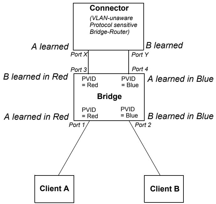
Figure B-1—Connecting independent VLANs—1
Clients A and B are connected via the protocol sensitive Bridge-Router (Connector), with an intervening VLAN-aware Bridge. The fact that all Ports of the Bridge carry untagged traffic neatly conceals the fact that the Connector has the effect of connecting VLANs Red and Blue together with regard to bridged traffic. The Connector learns A and B in the same database, as it has no knowledge of VLANs Red and Blue. This prevents any traffic transmitted on the Red VLAN (Port X of the Connector) that is destined for A, from being bridged to Port Y and transmitted on the Blue VLAN.
The VLAN-aware Bridge must keep its learning separate for Red and Blue; otherwise, the addresses of the two clients would be alternately learned on diagonally opposite Ports as, for example, traffic sourced by A reenters the Bridge on Port 4 having previously been seen on Port 1.
NOTE—This example assumes that Spanning Tree is disabled in the Connector, so that the VLAN-aware Bridge does not attempt to suppress the loop that apparently exists if VLANs are not taken into account.
A simpler example can be constructed, with a single Port connecting the Connector and the VLAN-aware Bridge, if the Connector is itself VLAN-aware and transmits and receives only VLAN-tagged traffic. In this case, the Connector would allocate a single FID for use by Red and Blue. This is shown in Figure B-2.
B.1.2 Duplicate MAC Addresses
The simplest example of a need for Independent VLAN Learning occurs where two (or more) distinct devices in different parts of the network reuse the same individual MAC Address, or where a single device is connected to multiple LAN segments, and all of its LAN interfaces use the same individual MAC Address. This is shown in Figure B-3.
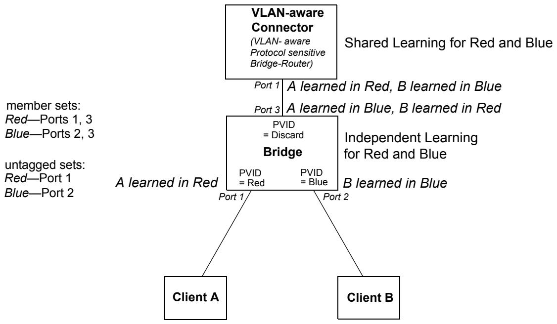
Figure B-2—Connecting independent VLANs—2
member sets:
Red—Ports 1, 3
Blue—Ports 2, 3
untagged sets:
Red—Port 1
Blue—Port 2
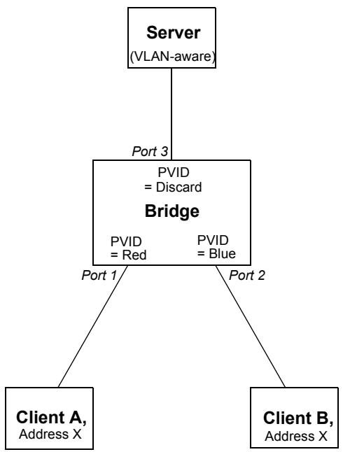
Figure B-3—Duplicate MAC Addresses
The example shows two clients with access to the same server; both clients are using the same individual MAC Address, X. If the Bridge shares learning between VLAN Red (which serves Client A) and VLAN Blue (which serves Client B), i.e., the Bridge uses the same FID for both VLANs, then Address X will appear to move between Ports 1 and 2 of the Bridge, depending on which client has most recently transmitted a frame. Communication between these Clients and the server will therefore be seriously disrupted. Assignment of distinct FIDs for Red and Blue ensures that communication can take place correctly.
Hence, in order to construct this particular VLAN configuration, either an IVL Bridge or an SVL/IVL Bridge would be required.
B.1.3 Asymmetric VLANs
A primary example of the requirement for Shared VLAN Learning is found in “asymmetric” uses of VLANs. Under normal circumstances, a pair of devices communicating in a VLAN environment will both send and receive using the same VLAN; however, there are some circumstances in which it is convenient to make use of two distinct VLANs, one used for A to transmit to B and the other used for B to transmit to A. An example of such an application of VLANs is shown in Figure B-4. Note that:
a) In the example, the server and both clients are assumed to be VLAN-unaware devices, i.e., they transmit and receive untagged frames only;
b) The ingress classification rules assumed by the example are as defined in this standard, i.e., Port-based classification only;
c) The configuration shown can only be achieved by management configuration of appropriate values in Static VLAN Registration Entries (8.8.9) in order to configure the indicated member sets and untagged sets.
member sets:
Purple - Ports 1 and 2
Red - Port 3
Blue - Port 3
untagged sets:
Purple - Ports 1 and 2
Red - Port 3
Blue - Port 3
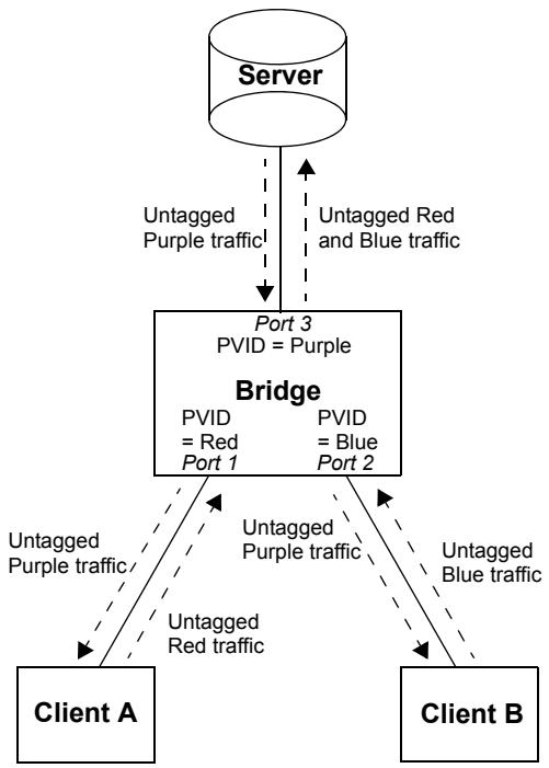
Figure B-4—Asymmetric VLAN use: “multi-netted server”
In the example, Port-based tagging and an asymmetric VLAN configuration is used in order to permit Clients A and B access to a common server, but to prohibit Clients A and B from talking to each other. Examples of where this type of configuration might be required are if the clients are on distinct IP subnets, or if there is some confidentiality-related need to segregate traffic between the clients.
Client A transmits to the server via Port 1, which will classify this traffic as belonging to VLAN Red; the Bridge, therefore, learns Client A's MAC Address on Port 1 in VLAN Red. The Server transmits its responses to Client A via Port 3, which classifies the return traffic as belonging to VLAN Purple. If individual MAC Address learning is configured in the Bridge such that learning is independent between Red and Purple (Red and Purple are allocated to distinct FIDs), then the Bridge will have no knowledge of A in VLAN Purple and will therefore flood the server's responses to Client A on both Port 1 and Port 2. Conversely, if Red and Purple are defined to share the same FID, then the address information learned in Red will be available for use in forwarding the Purple traffic, and the responses to Client A are forwarded only through Port 1.
Similarly, there is a need in this configuration for Blue and Purple to share learning information; hence, in order for this configuration to achieve its objectives, the Red, Blue, and Purple VIDs must be allocated to the same FID in the Bridge.
Hence, in order to construct this particular VLAN configuration, either an SVL Bridge or an SVL/IVL Bridge would be required.
NOTE—The example has been deliberately simplified; in practical applications, the central Bridge would likely be replaced by a number of VLAN-aware Bridges, interconnected with links that would carry the traffic between clients and server as VLAN-tagged frames, with VLAN-tagging and untagging occurring only at the “edge” Ports of the network. An alternative approach to the one described here could also be achieved either by using a VLAN-aware server or by use of more sophisticated ingress classification rules.
B.1.4 Generic constraints on SVL and IVL use
This subclause describes the general constraints on the mapping of VLANs to FIDs, from the point of view of a given Bridge that learns from or forwards frames on a set of VLANs (the Bridge's “active set” of VLANs). If
a) The individual MAC Addresses associated with each point of attachment to the active set of VLANs are unique (i.e., the “Duplicate MAC Address problem” is not present), and
b) There is no Bridge or Bridge-like device that takes frames from one VLAN in the active set and subsequently transmits them on another VLAN in the active set, then
every VLAN in the active set may share the same FID; in other words, individual MAC Address information learned in any one VLAN may be used in forwarding decisions taken relative to any of the others, so the SVL approach can be used in that Bridge.
Furthermore, if
c) Each bidirectional, individual MAC-Addressed, conversation between pairs of end stations makes use of the same VLAN (ID) in both directions, then
every VLAN in the active set may be allocated a distinct FID (with the possibility of a little extra flooding as learning of addresses in one VLAN does not contribute to forwarding decisions for that address in any other VLAN). Under these circumstances, rule b) may also be relaxed and restated as follows:
d) Frames on one VLAN in the active set may be received by (up to) one Bridge and transmitted on another VLAN in the active set, provided that there is no loop in such VLAN to VLAN forwarding, e.g., for a set of VLANs Red, Blue, and Green, there is no logical loop in copying frames between VLANs, such as copying from Red to Green by one Bridge, Green to Blue by another, and Blue back to Red by a third.
So
e) If rules a), b), and c) are true, and d) is false, for all VLANs in the active set, then either an SVL or an IVL Bridge can be deployed;
f) If rules a) and b) are true, and c) and d) are false for all VLANs in the active set, then only an SVL Bridge can be deployed;
g) If rules a) or b) or d) are false, and c) is true for all VLANs in the active set, then only an IVL Bridge can be deployed.
These conditions are all on the basis that they apply “for all VLANs in the active set.” Clearly, in more complex scenarios, some VLANs in the active set will have requirements that dictate SVL behavior on the part of a given Bridge, while others will have requirements that dictate IVL behavior. Under such circumstances, an SVL/IVL Bridge is required, allowing those VLANs that need to be shared to be mapped to a single FID, while those that need to be independent are mapped to distinct FIDs. Needless to say, wherever an SVL or IVL Bridge can be deployed, it can successfully be replaced by an appropriately configured SVL/IVL Bridge.
B.2 Configuring the Global VLAN Learning Constraints
Subclause B.1 described the requirements that exist for the two approaches to learning in Bridges, closing with some generic rules for how to determine whether, for a given Bridge, SVL, IVL, or SVL/IVL can be successfully deployed. In Bridges, the set of requirements for Independent and/or Shared VLAN Learning is configured as a set of global VLAN Learning Constraint specifications, using the management tools defined in 12.10.3. Two types of VLAN Learning Constraint are defined in 8.8.7.2, which also defines how the set of constraints is used in order to derive a valid mapping of VIDs to FIDs.
The constraint specifications can be constructed on a modular basis. For example, the configuration shown in Figure B-4 has a requirement for Shared VLAN Learning among VLANs Red, Blue, and Purple. This could be expressed as follows:
{Red S Purple}; {Blue S Purple}
with {Red S Blue} being implied by the transitive nature of the S Constraint.
If we add a similar server access configuration in the same network that requires Red to share with Yellow and Orange, then this could be expressed as
{Red S Yellow}; {Orange S Yellow}
with {Red S Orange}, {Yellow S Blue}, {Yellow S Purple}, {Orange S Blue}, and {Orange S Purple} being implied by the transitive nature of the S Constraint.
Hence, Red, Blue, Purple, Yellow, and Orange are all required to map to the same FID in order for the set of S Constraints (both explicit and implied) to be met. The constraints that express that requirement are built up from their constituent requirements; namely, for Red and Blue to share with Purple to meet one configuration need, and for Red to share with Yellow and Orange to meet another.
NOTE 1—The five VLANs in this example can be viewed as forming a Shared Set; i.e., a set of VLANs that have a mutual requirement to share learned information—all members of a Shared Set must map to the same FID. Any sequence of S Constraints defines one or more such Shared Sets. Any two Shared Sets can also map to the same FID as long as, for any pair of VLANs, one selected from each Shared Set, no I Constraints require that pair of VLANs to learn independently. Hence, if there are only S Constraints defined, then all VLANs can be mapped to a single FID.
Similarly, the I Constraints can be added on a modular basis. Continuing from the above example, a BridgeRouter (Figure B-1) might be present in the network, which has the effect of connecting VLANs Indigo and
Green together, thus creating a requirement for Indigo and Green to be independent. This could be expressed as
{Indigo I 1}; {Green I 1}
A separate independence requirement might be imposed by the fact that three stations, attached to Indigo, Vermilion, and Red VLANs, all make use of the same individual MAC Address. This could be expressed as:
  {Indigo I 2};
  {Vermilion I 2};
  {Red I 2}
Hence, {Indigo, Vermilion, Red} have to be mutually independent (assigned to distinct FIDs), {Indigo, Green} have to be mutually independent, and {Red, Blue, Purple, Yellow, Orange} have to be shared.
The minimum number of FIDs required to satisfy this total constraint specification is three, e.g.:
FID A: Red, Blue, Purple, Yellow, Orange
FID B: Indigo
FID C: Green, Vermilion
although an equally valid allocation for three FIDs is
FID A: Green, Red, Blue, Purple, Yellow, Orange
FID B: Indigo
FID C: Vermilion
and an equally valid allocation, using the maximum number of FIDs that could be used for this set of constraints and VLANS, is
FID A: Red, Blue, Purple, Yellow, Orange
FID B: Indigo
FID C: Green
FID D: Vermilion
NOTE 2—It can clearly be seen from this example that it is possible to add further constraints that result in impossible VID to FID mappings; for example, if we were to add {Indigo S Red} or ({Yellow I 3}, {Blue I 3}), then the result is at least one pair of VLANs that have a requirement to both share the same FID and to use distinct FIDs at the same time. Such configurations are examples of Learning Constraint inconsistencies (8.8.7.3).
The assumption behind these constraint specifications is that they are applied globally, in the sense that all Bridges in a given network are configured with the same set of constraints. This assumption is important to ensure that each Bridge is in a position to determine whether, given its current active set of VLANs, it is capable of adopting a VID to FID mapping that will satisfy the specified constraints. If it cannot achieve such a mapping (for any of the reasons identified in 8.8.7.3), then it has detected a network misconfiguration that can only be resolved by management intervention. The managed object specification 12.10.3 provides a Notification for use in such circumstances, to alert a management station to the existence of the problem.
B.3 Interoperability
If the configuration of the network is such that it is not necessary to configure any VLAN Learning Constraints into the Bridges, i.e.:
a) There are no instances where two (or more) points of attachment to different LAN segments (and different VLANs) make use of the same individual MAC Address;
b) There are no instances where a Bridge receives frames on one VLAN and transmits them on another VLAN;
c) There is no asymmetric VLAN use, i.e., there is no pair of end stations for which bidirectional, unicast conversations make use of different VLANs for each direction of transmission,
then it is possible to freely intermix SVL, IVL, and SVL/IVL Bridges in that network, and they can all successfully interoperate.
If the configuration of the network requires one or more S Constraints (and no I Constraints) to be configured into the Bridges, then SVL and SVL/IVL Bridges can be used freely; however, IVL Bridges may only be used in locations where their active set of VLANs does not include any pair of VLANs for which an S Constraint (either explicit or implied) has been defined.
If the configuration of the network requires two or more I Constraints (and no S Constraints) to be configured into the Bridges, then IVL and SVL/IVL Bridges can be used freely; however, SVL Bridges may only be used in locations where their active set of VLANs does not include any pair of VLANs for which I Constraints with the same Independent Set Identifier have been defined.
If the configuration of the network requires both I Constraints and S Constraints to be configured into the Bridges, then SVL/IVL Bridges can be used freely; however,
d) SVL Bridges may only be used in locations where their active set of VLANs does not include any pair of VLANs for which I Constraints with the same Independent Set Identifier have been defined, and
e) IVL Bridges may only be used in locations where their active set of VLANs does not include any pair of VLANs for which an S Constraint (either explicit, or implied) has been defined.
Annex C
(informative)
MAC method dependent aspects of VLAN support
This annex examines the set of services, frame formats, and MAC methods involved in the provision of VLAN services across IEEE 802 LANs using different MAC methods and the mapping/bridging functions necessary for that provision.
C.1 The variables
End station MAC Service users make use of MAC data transmission services that convey the following types of information:
a) Ethernet Type-encoded (E) and LLC-encoded (L) information;
b) Frames (either E or L) in which any MAC Addresses embedded in the MAC data are carried in Canonical (C) or Non-canonical (N) format;
NOTE 1—The terms Canonical format and Non-canonical format are described in IEEE Std 802.
c) Frames that carry source-routing information (R), or frames that are bridged transparently (T).
Hence, there are potentially eight combinations of these variables, corresponding to eight distinct services, as follows:
d) E-C-T (Ethernet Type-encoded, Canonical, transparent),
e) E-C-R (Ethernet Type-encoded, Canonical, source-routed),
f) E-N-T (Ethernet Type-encoded, Non-canonical, transparent),
g) E-N-R (Ethernet Type-encoded, Non-canonical, source-routed),
h) L-C-T (LLC-encoded, Canonical, transparent),
i) L-C-R (LLC-encoded, Canonical, source-routed),
j) L-N-T (LLC-encoded, Non-canonical, transparent),
k) L-N-R (LLC-encoded, Non-canonical, source-routed),
These services are supported over two basic LAN types:
1) IEEE 802.3/Ethernet (C);
m) Token Ring/FDDI (R).
Two VLAN environments are involved:
n) Untagged frames (U);
o) Tagged frames (T).
This leads to a total of 32 potential frame/encapsulation formats to consider $(8 \times 2 \times 2)$ . There are 96 possible one-way heterogeneous bridging functions between these various LAN/VLAN environments and 48 symmetrical (2-way) functions.
The combination of services and environments is illustrated in Figure C-1; italics indicate services that have no untagged representation on the MAC method concerned.
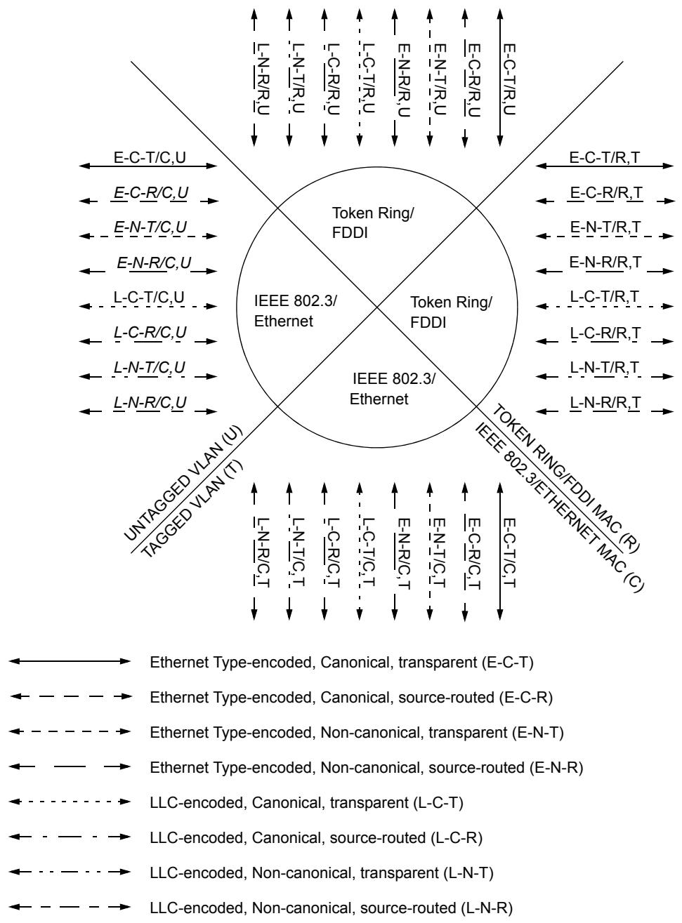
Figure C-1—Services and environments
Figure C-2 illustrates the heterogeneous Bridging functions involved. In this diagram, the bridging functions are labeled H, Q, or Q + H depending on whether the function involves IEEE Std 802.1H, IETF RFC 1042, and IETF RFC 1390 frame translation, IEEE Std 802.1Q VLAN-tagging/untagging/tag translation, or a combination of IEEE Std 802.1Q VLAN-tagging/untagging/tag translation and IEEE Std 802.1H, IETF RFC 1042, and IETF RFC 1390 frame translation.
NOTE 2—Figure C-2 is not intended to represent a real LAN, simply to illustrate the various Bridging functions.
In both diagrams, the frame formats involved are identified by three initial letters that identify the service provided, from the list of eight services above. The fourth letter indicates the MAC method that carries the frame (C or R), and the fifth letter indicates the type of VLAN (U or T).
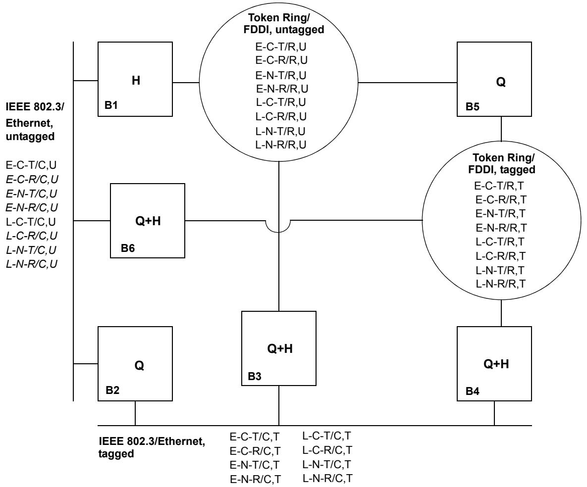
Figure C-2—Heterogeneous Bridging functions
C.2 Bridging functions
C.2.1 Bridging function B1
This function bridges between heterogeneous untagged VLAN environments. The following frame translations are involved:
a) IEEE Std 802.1H, IETF RFC 1042, and IETF RFC 1390 encapsulation/decapsulation for frames carrying Ethernet Type-encoded information.
b) IEEE Std 802.1D conversion for frames carrying LLC-encoded information.
c) Any requirements for translation from Canonical to Non-canonical address format, or vice versa, must be met if communication is to be maintained between end stations separated by this Bridging function.
d) Any source-routed traffic cannot be relayed between these environments, as there is no representation for source-routing information in untagged frames on IEEE 802.3/Ethernet LANs.
C.2.2 Bridging function B2
This function involves VLAN entry (I to T) and exit (T to I); it bridges between untagged and tagged IEEE 802.3/Ethernet environments. The frame translations involved are as follows:
a) Insertion of Ethernet-encoded tag headers on VLAN entry;
b) Removal of Ethernet-encoded tag headers on VLAN exit;
c) Translation of Non-canonical MAC Addresses to Canonical on VLAN exit;
d) Any source-routed traffic cannot be relayed between these environments, as there is no representation for source-routing information in untagged frames on IEEE 802.3/Ethernet LANs.
NOTE—VLAN entry in Non-canonical format does not occur, as the native representation on IEEE 802.3/Ethernet is Canonical format. VLAN exit of Non-canonical information can occur only if the Bridge is capable of translating the representation of embedded MAC Addresses to their Canonical format.
C.2.3 Bridging function B3
This function involves VLAN entry and exit; it bridges between tagged IEEE 802.3/Ethernet and untagged Ring environments. The following frame translations are involved:
a) For untagged Ethernet Type-encoded information on Token Ring/FDDI (VLAN entry): Removal of IEEE Std 802.1H, IETF RFC 1042, and IETF RFC 1390 encapsulation, and insertion of Ethernet-encoded tag header;
b) For tagged Ethernet Type-encoded information on IEEE 802.3/Ethernet (VLAN exit): Removal of tag header and insertion of IEEE Std 802.1H, IETF RFC 1042, and IETF RFC 1390 encapsulation;
c) For VLAN entry/exit with frames carrying LLC-encoded information: Insertion/removal of Ethernet-encoded tag header;
d) Translation of MAC Addresses to the format appropriate for the destination Ring on VLAN exit;
e) Any source-routing information present in the frame is preserved; the Token Ring/FDDI RIF is copied into the E-RIF in the Ethernet-encoded tag header on VLAN entry (with the CFI/NCFI flags set appropriately), and copied back on exit.
NOTE—VLAN entry (tagged IEEE 802.3/Ethernet from untagged Token Ring/FDDI) in Canonical format normally occurs only from ISO/IEC 9314-2, as the native representation on IEEE Std 802.5 is Non-canonical format, and for ISO/IEC 9314-2 is Canonical format. Hence, VLAN exit in Canonical format onto IEEE Std 802.5 can occur only if the Bridge is capable of translating the representation of embedded MAC Addresses; i.e., of converting the frame from Canonical on IEEE 802.3/Ethernet to Non-canonical on IEEE Std 802.5. Similarly, VLAN exit in Non-canonical format onto ISO/IEC 9314-2 can occur only if the Bridge is capable of converting the frame from Non-canonical on IEEE 802.3/Ethernet to Canonical on ISO/IEC 9314-2.
C.2.4 Bridging function B4
This function bridges between tagged IEEE 802.3/Ethernet and Ring environments. The following frame translations are involved:
a) For tagged Ethernet Type-encoded information on Token Ring/FDDI to IEEE 802.3/Ethernet: Removal of IEEE Std 802.1H, IETF RFC 1042, and IETF RFC 1390 encapsulation, and conversion of the tag header to the Ethernet-encoded form;
b) For tagged Ethernet Type-encoded information on IEEE 802.3/Ethernet to Token Ring/FDDI: IEEE Std 802.1H, IETF RFC 1042, and IETF RFC 1390 encapsulation, and conversion of the tag header to the SNAP-encoded form;
c) For tagged frames carrying LLC-encoded information: conversion of the tag header between the SNAP-encoded and Ethernet-encoded forms;
d) Any source-routing information is preserved between these environments by copying between the Token Ring/FDDI RIF and the E-RIF in the Ethernet-encoded tag header.
NOTE 1—This Bridging function is not required to modify the format of embedded MAC Addresses.
NOTE 2—In FDDI LANs, source-routing information may be present either in an E-RIF within the tag header or in the normal position for a source-routed frame.
C.2.5 Bridging function B5
This function involves VLAN entry and exit; it bridges between tagged and untagged Ring environments. The frame translations involved are as follows:
a) Insertion of SNAP-encoded tag header on VLAN entry;
b) Removal of SNAP-encoded tag header on VLAN exit;
c) Translation of MAC Addresses to the format appropriate for the destination Ring on VLAN exit;
d) Any source-routing information present in the frame is preserved.
NOTE 1—VLAN entry in Canonical format normally occurs only from ISO/IEC 9314-2, as the native representation on IEEE Std 802.5 is Non-canonical format, and for ISO/IEC 9314-2 is Canonical format. Hence, VLAN exit in Canonical format onto IEEE Std 802.5 can occur only if the Bridge is capable of translating the representation of embedded MAC Addresses; i.e., of converting the frame from Canonical on IEEE 802.3/Ethernet to Non-canonical on IEEE Std 802.5. Similarly, VLAN exit in Non-canonical format onto ISO/IEC 9314-2 can occur only if the Bridge is capable of converting the frame from Non-canonical on IEEE 802.3/Ethernet to Canonical on ISO/IEC 9314-2.
NOTE 2—In FDDI LANs, source-routing information may be present either in an E-RIF within the tag header or in the normal position for a source-routed frame.
C.2.6 Bridging function B6
This function involves VLAN entry and exit; it bridges between untagged IEEE 802.3/Ethernet and tagged Ring environments. The following frame translations are involved:
a) For untagged Ethernet Type-encoded information on IEEE 802.3/Ethernet (VLAN entry): IEEE Std 802.1H, IETF RFC 1042, and IETF RFC 1390 encapsulation, and insertion of SNAP-encoded tag header;
b) For tagged Ethernet Type-encoded information on Token Ring/FDDI (VLAN exit): Removal of SNAP-encoded tag header and removal of IEEE Std 802.1H, IETF RFC 1042, and IETF RFC 1390 encapsulation;
c) For VLAN entry/exit with frames carrying LLC-encoded information: Insertion/removal of SNAP-encoded tag header;
d) Any source-routed traffic cannot be relayed between these environments, as there is no representation for source-routing information in untagged frames on IEEE 802.3/Ethernet LANs.
NOTE 1—VLAN entry in Non-canonical format does not occur, as the native representation on IEEE 802.3/Ethernet is Canonical format. VLAN exit of Non-canonical format can occur only if the Bridge is capable of translating the representation of embedded MAC Addresses; i.e., of converting the frame from Non-canonical format to Canonical format on IEEE 802.3/Ethernet.
NOTE 2—In FDDI LANs, source-routing information may be present either in an E-RIF within the tag header or in the normal position for a source-routed frame.
C.3 Frame formats
The following abbreviations are used in the descriptions of the frame formats in this annex, with the following meanings:
AC Access Control field—in Token Ring frames only (see IEEE Std 802.5 and NOTE at the end of this subclause)
RCI Ring Control Information—AC (if present) plus FC fields
DA Destination MAC Address
SA Source MAC Address
PT Ethernet Protocol Type
SPT SNAP-encoded Ethernet Protocol Type (C.6.1)
TPID Tag Protocol ID (9.6)
ETPID Ethernet-encoded TPID (9.6)
STPID SNAP-encoded TPID (9.6)
TCI Tag Control Information (9.6)
CFI Canonical Format Indicator (9.6)
NCFI Non-canonical Format Indicator (9.6)
C Canonical
N Non-canonical
R E-RIF present
VID VLAN Identifier (9.6)
Len IEEE 802.3-style Length/Type field (C.6.2)
LLC LLC addressing and control information
RIF Source-Routing Information Field (C.6.4)
E-RIF Embedded RIF (9.7, C.6.4)
C-Data MAC user data in which any embedded MAC Addresses are in Canonical format (C.6.3)
N-Data MAC user data in which any embedded MAC Addresses are in Non-canonical format
PAD Padding (C.6.5)
FCS Frame Check Sequence
In C.3.2, the possible frame formats are categorized by service type; in C.3.3 they are categorized by bearer MAC method and tagging method.
NOTE—The text in this annex makes the generalization of treating the FC fields in IEEE Std 802.5 and FDDI as if they are the same, in order to simplify the descriptions as much as possible. In reality, there are detailed differences between FC fields in the two MAC methods. When translating between IEEE Std 802.5 and FDDI, the most likely behavior is to propagate the “LLC frame” indication and the Priority field between the FC octets on input and output.
C.3.1 Structure of the tagged frame
Figure C-3 provides an illustrative example of a single tagged Ethernet Type-encoded frame format as used in an Ethernet to Ethernet bridge. This illustration is only of the simplest case, that is, a single-level, fixed-size tagging between identical MACs. $^{21}$
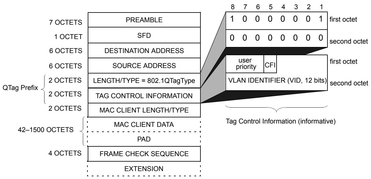
Figure C-3—Tagged IEEE 802.3 MAC frame format
Figure C-4 illustrates the frame formats used for carrying tagged Ethernet Type-encoded information and LLC-encoded information using 8802-5 Token Ring MAC methods.
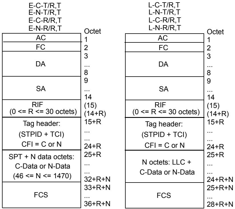
Figure C-4—Tagged frames on 8802-5 Token Ring LANs
Figure C-5 illustrates the frame formats used for carrying tagged Ethernet Type-encoded information and LLC-encoded information using FDDI MAC methods. Two forms of tagged frame are shown as follows:
a) The source-routed form, in which the frame carries a RIF in the normal position, following the source MAC Address. This form can only be used on FDDI LANs that support source routing; and
b) The transparent form, in which an E-RIF is present in the tag header if the frame carries Non-canonical or source-routed information.
Figure C-6 illustrates the frame formats used for carrying tagged Ethernet Type-encoded information and LLC-encoded information on IEEE 802.3/Ethernet MAC methods.
As can be seen from these diagrams, the major differences between the tagged frame formats in IEEE 802.3/Ethernet and Token Ring/FDDI MAC methods are as follows:
c) The presence/absence of RCI (Ring Control Information);
d) The position of the RIF and E-RIF fields;
e) The encoding used to carry the Tag Protocol Identifier (2 octets for ETPID vs. 8 octets for STPID);
f) The encoding used to carry Ethernet Protocol Types (2 octets for PT vs. 8 octets for SPT);
g) The presence/absence of the Length/Type field;
h) The presence/absence of the PAD field.
The diagrams also illustrate the similarities between:
i) The format of tagged frames on 8802-5 and the source-routed form of tagged frames on FDDI;
j) The format of tagged frames on 802.3/Ethernet and the transparent form of tagged frames on FDDI.
C.3.2 Frame formats by service type
C.3.2.1 Frame formats for Ethernet Type-encoded service
C.3.2.1.1 Ethernet Type-encoded, Canonical, transparent
E-C-T/C,U: DA, SA, PT, C-Data, FCS
E-C-T/C,T: DA, SA, ETPID, TCI (CFI=C), PT, C-Data, FCS
E-C-T/R,U: RCI, DA, SA (RII reset), SPT, C-Data, FCS
E-C-T/R,T: RCI, DA, SA (RII reset), STPID, TCI (CFI=C), SPT, C-Data, FCS
C.3.2.1.2 Ethernet Type-encoded, Canonical, source-routed
E-C-R/C,U: No representation possible
E-C-R/C,T: DA, SA, ETPID, TCI (CFI=R), PT, E-RIF (NCFI=C), C-Data, FCS
E-C-R/R,U: RCI, DA, SA (RII set), RIF, SPT, C-Data, FCS
E-C-R/R,T: RCI, DA, SA (RII set), RIF, STPID, TCI (CFI=C), SPT, C-Data, FCS (source-routed form)
E-C-R/R,T: RCI, DA, SA (RII reset), STPID, TCI (CFI=R), E-RIF (NCFI=C), SPT, C-Data, FCS (transparent form)
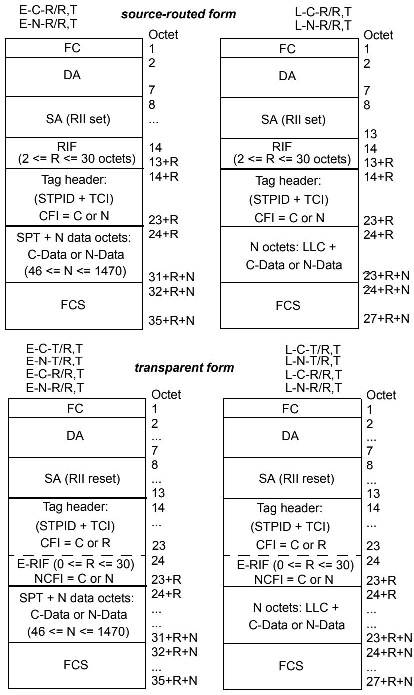
Figure C-5—Tagged frames on FDDI LANs
C.3.2.1.3 Ethernet Type-encoded, Non-canonical, transparent
E-N-T/C,U: No representation possible
E-N-T/C,T: DA, SA, ETPID, TCI (CFI=R), PT, E-RIF (NCFI=N), N-Data, FCS
E-N-T/R,U: RCI, DA, SA (RII reset), SPT, N-Data, FCS
E-N-T/R,T: RCI, DA, SA (RII reset), STPID, TCI (CFI =N), SPT, N-Data, FCS
(8802-5 Token Ring form)
E-N-T/R,T: RCI, DA, SA (RII reset), STPID, TCI (CFI=R), E-RIF (NCFI=N), SPT, N-Data, FCS
(FDDI form)
<table><tr><td>E-C-T/C,T</td><td>Octet</td></tr><tr><td rowspan="2">DA</td><td>1</td></tr><tr><td>6</td></tr><tr><td rowspan="2">SA</td><td>7</td></tr><tr><td>12</td></tr><tr><td rowspan="4">Tag header: ETPID+ TCI, CFI = C</td><td>13</td></tr><tr><td>14</td></tr><tr><td>15</td></tr><tr><td>16</td></tr><tr><td rowspan="3">PT</td><td>17</td></tr><tr><td>18</td></tr><tr><td>19</td></tr><tr><td rowspan="2">N C-Data octets(46 <= N <= 1496)</td><td></td></tr><tr><td>N+18</td></tr><tr><td rowspan="2">FCS</td><td>N+19</td></tr><tr><td>N+22</td></tr></table>
<table><tr><td>L-C-T/C,T</td><td>Octet</td></tr><tr><td rowspan="2">DA</td><td>1</td></tr><tr><td>6</td></tr><tr><td rowspan="2">SA</td><td>7</td></tr><tr><td>12</td></tr><tr><td rowspan="4">Tag header: ETPID+ TCI, CFI = C</td><td>13</td></tr><tr><td>14</td></tr><tr><td>15</td></tr><tr><td>16</td></tr><tr><td rowspan="3">LEN</td><td>17</td></tr><tr><td>18</td></tr><tr><td>19</td></tr><tr><td rowspan="2">N octets:LLC + C-Data + PAD(42 <= N <= 1496)</td><td>N+18</td></tr><tr><td>N+19</td></tr><tr><td>FCS</td><td>N+22</td></tr></table>
<table><tr><td>E-N-T/C,T E-C-R/C,T E-N-R/C,T</td><td>Octet</td></tr><tr><td rowspan="2">DA</td><td>1</td></tr><tr><td>6</td></tr><tr><td rowspan="2">SA</td><td>7</td></tr><tr><td>12</td></tr><tr><td rowspan="3">Tag header: ETPID + TCI, CFI = R</td><td>13</td></tr><tr><td>14</td></tr><tr><td>15</td></tr><tr><td>PT</td><td>16</td></tr><tr><td rowspan="3">E-RIF (2 <= R <= 30) NCFI = C or N</td><td>17</td></tr><tr><td>18</td></tr><tr><td>19</td></tr><tr><td rowspan="3">N octets: C-Data or N-Data (46 <= N <= 1470)</td><td>R+18</td></tr><tr><td>R+19</td></tr><tr><td></td></tr><tr><td rowspan="3">FCS</td><td>R+N+18</td></tr><tr><td>R+N+19</td></tr><tr><td>R+N+22</td></tr></table>
<table><tr><td>L-N-T/C,T</td><td rowspan="3">Octet</td></tr><tr><td>L-C-R/C,T</td></tr><tr><td>L-N-R/C,T</td></tr><tr><td>DA</td><td>1</td></tr><tr><td rowspan="2">SA</td><td>6</td></tr><tr><td>7</td></tr><tr><td rowspan="4">Tag header: ETPID + TCI, CFI = R</td><td>12</td></tr><tr><td>13</td></tr><tr><td>14</td></tr><tr><td>15</td></tr><tr><td>LEN</td><td>16</td></tr><tr><td>E-RIF(2 <= R <= 30)</td><td>17</td></tr><tr><td rowspan="2">NCFI = C or N</td><td>18</td></tr><tr><td>19</td></tr><tr><td rowspan="3">N octets: LLC + C-Data + PAD or LLC + N-Data + PAD(42-R <= N <= 1470)</td><td>R+18</td></tr><tr><td>R+19</td></tr><tr><td>R+N+18</td></tr><tr><td rowspan="2">FCS</td><td>R+N+19</td></tr><tr><td>R+N+22</td></tr></table>
Figure C-6—Tagged frames on 802.3/Ethernet LANs
C.3.2.1.4 Ethernet Type-encoded, Non-canonical, source-routed
E-N-R/C,U: No representation possible
E-N-R/C,T: DA, SA, ETPID, TCI (CFI=R), PT, E-RIF (NCFI=N), N-Data, FCS
E-N-R/R,U: RCI, DA, SA (RII set), RIF, SPT, N-Data, FCS
E-N-R/R,T: RCI, DA, SA (RII set), RIF, STPID, TCI (CFI=N), SPT, N-Data, FCS (source-routed form)
E-N-R/R,T: RCI, DA, SA (RII reset), STPID, TCI (CFI=R), E-RIF (NCFI=N), N-Data, FCS (transparent form)
C.3.2.2 Frame formats for LLC-encoded service
C.3.2.2.1 LLC-encoded, Canonical, transparent
L-C-T/C,U: DA, SA, LEN, LLC, C-Data, PAD, FCS
L-C-T/C,T: DA, SA, ETPID, TCI (CFI=C), LEN, LLC, C-Data, PAD, FCS
L-C-T/R,U: RCI, DA, SA (RII reset), LLC, C-Data, FCS
L-C-T/R,T: RCI, DA, SA (RII reset), STPID, TCI (CFI=C), LLC, C-Data, FCS
C.3.2.2.2 LLC-encoded, Canonical, source-routed
L-C-R/C,U: No representation possible
L-C-R/C,T: DA, SA, ETPID, TCI (CFI=R), LEN, E-RIF (NCFI=C), LLC, C-Data, PAD, FCS
L-C-R/R,U: RCI, DA, SA (RII set), RIF, LLC, C-Data, FCS
L-C-R/R,T: RCI, DA, SA (RII set), RIF, STPID, TCI (CFI=C), LLC, C-Data, FCS (source-routed form)
L-C-R/R,T: RCI, DA, SA (RII reset), STPID, TCI (CFI=R), E-RIF (NCFI=C), LLC, C-Data, FCS (transparent form)
C.3.2.2.3 LLC-encoded, Non-canonical, transparent
L-N-T/C,U: No representation possible
L-N-T/C,T: DA, SA, ETPID, TCI (CFI=R), LEN, E-RIF (NCFI=N), LLC, N-Data, PAD, FCS
L-N-T/R,U: RCI, DA, SA (RII reset), LLC, N-Data, FCS
L-N-T/R,T: RCI, DA, SA (RII reset), STPID, TCI (CFI=N), LLC, N-Data, FCS (8802-5 Token Ring form)
L-N-T/R,T: RCI, DA, SA (RII reset), STPID, TCI (CFI=R), E-RIF (NCFI=N), LLC, N-Data, FCS (FDDI form)
C.3.2.2.4 LLC-encoded, Non-canonical, source-routed
L-N-R/C,U: No representation possible
L-N-R/C,T: DA, SA, ETPID, TCI (CFI=R), LEN, E-RIF (NCFI=N), LLC, N-Data, PAD, FCS
L-N-R/R,U: RCI, DA, SA (RII set), RIF, LLC, N-Data, FCS
L-N-R/R,T: RCI, DA, SA (RII set), RIF, STPID, TCI (CFI=N), LLC, N-Data, FCS (source-routed form)
L-N-R/R,T: RCI, DA, SA (RII reset), STPID, TCI (CFI=R), E-RIF (NCFI=N), LLC, N-Data, FCS (transparent form)
C.3.3 Frame formats by MAC method type and tagging method
C.3.3.1 Frame formats for IEEE 802.3/Ethernet MAC methods
C.3.3.1.1 IEEE 802.3/Ethernet, untagged
E-C-T/C,U: DA, SA, PT, C-Data, FCS
E-C-R/C,U: No representation possible
E-N-T/C,U: No representation possible
E-N-R/C,U: No representation possible
L-C-T/C,U: DA, SA, LEN, LLC, C-Data, PAD, FCS
L-C-R/C,U: No representation possible
L-N-T/C,U: No representation possible
L-N-R/C,U: No representation possible
C.3.3.1.2 IEEE 802.3/Ethernet, tagged
E-C-T/C,T: DA, SA, ETPID, TCI (CFI=C), PT, C-Data, FCS
E-C-R/C,T: DA, SA, ETPID, TCI (CFI=R), PT, E-RIF (NCFI=C), C-Data, FCS
E-N-T/C,T: DA, SA, ETPID, TCI (CFI=R), PT, E-RIF (NCFI=N), N-Data, FCS
E-N-R/C,T: DA, SA, ETPID, TCI (CFI=R), PT, E-RIF (NCFI=N), N-Data, FCS
L-C-T/C,T: DA, SA, ETPID, TCI (CFI=C), LEN, LLC, C-Data, PAD, FCS
L-C-R/C,T: DA, SA, ETPID, TCI (CFI=R), LEN, E-RIF (NCFI=C), LLC, C-Data, PAD, FCS
L-N-T/C,T: DA, SA, ETPID, TCI (CFI=R), LEN, E-RIF (NCFI=N), LLC, N-Data, PAD, FCS
L-N-R/C,T: DA, SA, ETPID, TCI (CFI=R), LEN, E-RIF (NCFI=N), LLC, N-Data, PAD, FCS
C.3.3.2 Frame formats for Token Ring/FDDI MAC methods
C.3.3.2.1 Token Ring/FDDI, untagged
E-C-T/R,U: RCI, DA, SA (RII reset), SPT, C-Data, FCS
E-C-R/R,U: RCI, DA, SA (RII set), RIF, SPT, C-Data, FCS
E-N-T/R,U: RCI, DA, SA (RII reset), SPT, N-Data, FCS
E-N-R/R,U: RCI, DA, SA (RII set), RIF, SPT, N-Data, FCS
L-C-T/R,U: RCI, DA, SA (RII reset), LLC, C-Data, FCS
L-C-R/R,U: RCI, DA, SA (RII set), RIF, LLC, C-Data, FCS
L-N-T/R,U: RCI, DA, SA (RII reset), LLC, N-Data, FCS
L-N-R/R,U: RCI, DA, SA (RII set), RIF, LLC, N-Data, FCS
C.3.3.2.2 Token Ring/FDDI, tagged
E-C-T/R,T: RCI, DA, SA (RII reset), STPID, TCI (CFI=C), SPT, C-Data, FCS
E-C-R/R,T: RCI, DA, SA (RII set), RIF, STPID, TCI (CFI=C), SPT, C-Data, FCS (source-routed form)
E-C-R/R,T: RCI, DA, SA (RII reset), STPID, TCI (CFI=R), E-RIF (NCFI=C), SPT, C-Data, FCS (transparent form)
E-N-T/R,T: RCI, DA, SA (RII reset), STPID, TCI (CFI=N), SPT, N-Data, FCS (8802-5 Token Ring form)
E-N-T/R,T: RCI, DA, SA (RII reset), STPID, TCI (CFI=R), E-RIF (NCFI=N), SPT, N-Data, FCS (FDDI form)
E-N-R/R,T: RCI, DA, SA (RII set), RIF, STPID, TCI (CFI=N), SPT, N-Data, FCS (source-routed form)
E-N-R/R,T: RCI, DA, SA (RII reset), STPID, TCI (CFI=R), E-RIF (NCFI=N), N-Data, FCS (transparent form)
<table><tr><td>L-C-T/R,T:</td><td>RCI, DA, SA (RII reset), STPID, TCI (CFI=C), LLC, C-Data, FCS</td></tr><tr><td>L-C-R/R,T:</td><td>RCI, DA, SA (RII set), RIF, STPID, TCI (CFI=C), LLC, C-Data, FCS(source-routed form)</td></tr><tr><td>L-C-R/R,T:</td><td>RCI, DA, SA (RII reset), STPID, TCI (CFI=R), E-RIF (NCFI=C), LLC, C-Data, FCS(transparent form)</td></tr><tr><td>L-N-T/R,T:</td><td>RCI, DA, SA (RII reset), STPID, TCI (CFI=N), LLC, N-Data, FCS(8802-5 Token Ring form)</td></tr><tr><td>L-N-T/R,T:</td><td>RCI, DA, SA (RII reset), STPID, TCI (CFI=R), E-RIF (NCFI=N), LLC, N-Data, FCS(FDDI form)</td></tr><tr><td>L-N-R/R,T:</td><td>RCI, DA, SA (RII set), RIF, STPID, TCI (CFI=N), LLC, N-Data, FCS(source-routed form)</td></tr><tr><td>L-N-R/R,T:</td><td>RCI, DA, SA (RII reset), STPID, TCI (CFI=R), E-RIF (NCFI=N), LLC, N-Data, FCS(transparent form)</td></tr></table>
C.4 Procedures for tagging, untagging, and relaying tagged frames
The formal definition of the procedures whereby tag headers are added and removed, and tagged frames are relayed are embodied in Clause 7 and Clause 8. This informal description is included in order to add clarity to the formal definition of the process.
C.4.1 Tagging
Subclauses C.4.1.1 through C.4.1.4 describe the translations that are performed when an untagged frame is relayed in tagged form.
C.4.1.1 MAC header information
The RCI, DA, SA, and RIF fields (if supported in the source frame and/or destination MAC methods) are translated from their representation in the source frame into the equivalent representation in the destination frame in accordance with the procedures described in IEEE Std 802.1D. This will result in
a) Preservation of the AC (Token Ring to Token Ring only) and FC fields (Token Ring/FDDI to Token Ring/FDDI only);
b) Translation of the DA and SA into their equivalent representation in the destination MAC methods;
c) Preservation of the RIF field, if present; either in its conventional position (Token Ring/FDDI to Token Ring/FDDI, source-routed form) or within the tag header (Token Ring/FDDI to IEEE 802.3/Ethernet or FDDI, transparent form).
NOTE—The ability of the tag header to carry source-routing information across IEEE 802.3/Ethernet LANs does not imply a requirement on the part of a pure IEEE 802.3/Ethernet Bridge to support source routing. This capability is provided simply to allow traffic that originates in, and is destined for, a source-routed environment to transit as tagged traffic across a non-source-routed environment. Similarly, this capability allows source-routed traffic to transit an FDDI network that is otherwise unable to support source routing.
C.4.1.2 Tag header insertion
The tag header is inserted immediately following the SA field (if no RIF is present in the destination frame) or immediately following the RIF field (if RIF is present in the destination frame). The header contains
a) An Ethernet-encoded TPID (destination MAC method is IEEE 802.3/Ethernet) or a Snap-encoded TPID (destination MAC method is Token Ring/FDDI);
b) A TCI field, as follows:
1) The PCP is set in accordance with the procedure described in IEEE Std 802.1D;
2) The CFI flag, indicating C/N (8802-5 Token Ring, and source-routed FDDI MAC methods), or C/[RIF present] (IEEE 802.3/Ethernet and transparent FDDI MAC methods), in accordance with the format of the MAC user data;
3) The VID field is set to the VID of the VLAN to which the source frame belongs.
c) An E-RIF field, immediately following the Length/Type field (IEEE 802.3/Ethernet and transparent FDDI MAC methods), if the frame is carrying Non-canonical data and/or source-routing information. The NCFI in the RIF indicates C or N, in accordance with the format of the MAC user data.
C.4.1.3 Ethernet Type-encoded data
If the MAC user data carries Ethernet Type-encoded data, i.e., the protocol identifier is an Ethernet Type value or an Ethernet Type value that has been SNAP encoded as described in IEEE Std 802.1D and IEEE Std 802.1H, and if the frame is being relayed between differing MAC methods (IEEE 802.3/Ethernet to or from Token Ring/FDDI), then the data is translated from the source format to the format appropriate to the destination MAC method in accordance with the procedures described in IEEE Std 802.1D and IEEE Std 802.1H.
C.4.1.4 FCS
When tagging a frame and performing the attendant field translations, it is necessary to recompute the Frame Check Sequence (FCS) field of the tagged frame. As stated in IEEE Std 802.1D, 6.3.7, the Bridge shall not introduce additional undetected frame errors as a result of such FCS recomputation.
NOTE—Where necessary in order to preserve the protection afforded by the original FCS, it is possible to incrementally compute the new FCS value, based on the original FCS, adjusted for the new fields added and the frame length. This technique, and other techniques for preserving FCS integrity, are discussed in IEEE Std 802.1D, Annex F.
C.4.2 Untagging
Subclauses C.4.2.1 through C.4.2.4 describe the frame translations that are performed when a received tagged frame is relayed in untagged format.
C.4.2.1 MAC header information
The RCI, DA, SA, and RIF or E-RIF fields (if supported in the source frame and/or destination MAC methods) are translated from their representation in the source frame into the equivalent representation in the destination frame in accordance with the procedures described in IEEE Std 802.1D. This will result in
a) Preservation of the AC (Token Ring to Token Ring only) and FC fields (Token Ring/FDDI to Token Ring/FDDI only);
b) Translation of the DA and SA into their equivalent representation in the destination MAC method;
c) Preservation of any source-routing information carried in the source frame, if present, and if the destination MAC method is a Token Ring/FDDI LAN that supports source routing. (If the source MAC method is IEEE 802.3/Ethernet or transparent FDDI and the tag header carries an E-RIF in which the RT field indicates a transparent frame, then the E-RIF is not considered to be carrying any source-routing information.)
C.4.2.2 Tag header
The tag header is removed.
C.4.2.3 Ethernet Type-encoded data
If the frame carries Ethernet Type-encoded data, i.e., the protocol identifier is an Ethernet Type value or an Ethernet Type value that has been SNAP encoded as described in IEEE Std 802.1D and IEEE Std 802.1H, and if the frame is being relayed between differing MAC methods (IEEE 802.3/Ethernet to or from Token Ring/FDDI), then the data are translated from the source format to the format appropriate to the destination MAC method in accordance with the with the procedures described in IEEE Std 802.1D and IEEE Std 802.1H.
C.4.2.4 Address translation
If the CFI/NCFI information in the tagged frame indicates that embedded addresses are being carried in a format inappropriate to the destination MAC method, then it is necessary either to translate the addresses from C to N or vice versa, or to discard the frame if such translation is not supported by the Bridge.
C.4.2.5 FCS
When removing a frame's VLAN tag and performing the attendant field translations, it is necessary to recompute the Frame Check Sequence (FCS) field of the tagged frame. As stated in IEEE Std 802.1D, 6.3.7, the Bridge shall not introduce additional undetected frame errors as a result of such an FCS recomputation.
NOTE—Where necessary in order to preserve the protection afforded by the original FCS, it is possible to incrementally compute the new FCS value, based on the original FCS, adjusted for the new fields added and the frame length. This technique, and other techniques for preserving FCS integrity, are discussed in IEEE Std 802.1D, Annex F.
C.4.3 Relaying tagged frames
Subclauses C.4.3.1 through C.4.3.4 describes the frame translations that are performed when a received tagged frame is relayed in tagged format.
C.4.3.1 MAC header information
The RCI, DA, and SA (if supported in the source frame and/or destination frame formats) are translated from their representation in the source frame into the equivalent representation in the destination frame in accordance with the procedures described in IEEE Std 802.1D.
For source-routed Token Ring/FDDI to IEEE 802.3/Ethernet or transparent FDDI, the RIF field (if present) is translated into the E-RIF field of the destination frame.
For relay between source-routed Token Ring/FDDI environments, the RIF (if present) is copied into the RIF field of the destination frame.
For IEEE 802.3/Ethernet or transparent FDDI to source-routed Token Ring/FDDI, the E-RIF field, if present, is translated into the RIF of the destination frame, with the NCFI bit reset, unless the E-RIF indicates that the frame is a transparent frame; in which case, the E-RIF is discarded.
This will result in
a) Preservation of the AC (Token Ring to Token Ring only) and FC fields (Token Ring/FDDI to Token Ring/FDDI only);
b) Translation of the DA and SA into their equivalent representation in the destination MAC method;
c) Preservation of any information carried in the E-RIF or RIF field, if present and if it carries source-routing information.
C.4.3.2 Tag header
If the source and destination MAC methods differ, the tag header is modified as follows:
a) The TPID field is set in accordance with the destination MAC method. An Ethernet-encoded TPID is used where the destination MAC method is IEEE 802.3/Ethernet; a Snap-encoded TPID is used where the destination MAC method is Token Ring/FDDI;
b) The information carried in the Priority and VID fields in the TCI are copied unchanged into the destination frame's TCI.
c) If the source and destination MAC methods are of the same type, then the CFI (and RIF, if present in IEEE 802.3/Ethernet) are copied unchanged into the destination tag header.
d) If the source and destination MAC methods differ, then the CFI information in the source tag header is translated into the format appropriate for the destination tag header.
C.4.3.3 Ethernet Type-encoded data
If the frame carries Ethernet Type-encoded data, i.e., the protocol identifier is an Ethernet Type value or an Ethernet Type value that has been SNAP encoded as described in IEEE Std 802.1D and IEEE Std 802.1H, and if the frame is being relayed between differing MAC methods (IEEE 802.3/Ethernet to or from Token Ring/FDDI), then the data are translated from the source format to the format appropriate to the destination MAC method in accordance with the with the procedures described in IEEE Std 802.1D and IEEE Std 802.1H.
C.4.3.4 FCS
When relaying tagged frames, if it is necessary to perform any attendant field translations, then it is necessary to recompute the Frame Check Sequence (FCS) field of the tagged frame. As stated in 6.3.7 of IEEE Std 802.1D, the Bridge shall not introduce additional undetected frame errors as a result of such FCS recomputation.
NOTE—Where necessary in order to preserve the protection afforded by the original FCS, it is possible to incrementally compute the new FCS value, based on the original FCS, adjusted for the new fields added and the frame length. This technique and other techniques for preserving FCS integrity are discussed in IEEE Std 802.1D, Annex F.
C.4.4 Padding and frame size considerations
C.4.4.1 Treatment of PAD fields in IEEE Std 802.3 frames
The minimum frame size constraint placed on IEEE 802.3/Ethernet frames requires frames to carry zero or more pad octets following the MAC client data, in order to ensure that no frame of total length less than 64 octets is transmitted on the medium. This requirement means that frames whose overall length would otherwise be less than 64 octets in length have (64-len) octets of padding added after the MAC client data, where len is the size of the frame before padding.
When tagged frames are transmitted by a Bridge on an IEEE Std 802.3 MAC, there are two permissible approaches (7.2), as follows:
a) Keep the minimum frame size generated by the Bridge equal to 64 octets. This implies that the number of pad octets in a received untagged IEEE Std 802.3 frame would be reduced by up to 4 octets when that frame was tagged;
b) Adopt a minimum tagged frame length of 68 octets. This implies that the number of pad octets in a received untagged IEEE Std 802.3 frame would not be adjusted when tagging such frames; equally, if subsequently untagged, no pad adjustment would be necessary before transmission on IEEE 802.3/Ethernet.
There is a similar choice to be made in end stations that generate tagged frames:
c) In some existing implementations, the decision as to whether pad octets are needed will be made at a point where it is impractical to distinguish between tagged and untagged frames. In these cases, the end station will use a minimum frame size of 64 octets for all frames;
d) In other cases, the padding decision will be taken at a point before it is known whether the frame will be transmitted tagged or untagged. In these cases, the end station will use a minimum tagged frame size of 68 octets and a minimum of 64 octets for untagged frames.
These approaches are all consistent with the IEEE Std 802.3 frame specification, as amended by IEEE Std 802.3ac-1998.
The implication is that, for correct operation on IEEE 802.3/Ethernet, all devices have to be capable of correctly handling tagged frames of less than 68 octets in length (C.4.4.3).
C.4.4.2 Maximum PDU size
VLAN tagging of an untagged frame, or relaying frames in tagged frame format, can result in an increase in the length of the original frame. If transmission of a given frame in tagged frame format through a given destination Port would result in violation of the maximum PDU size for the destination MAC method, the Bridge discards the frame for that destination Port.
NOTE—Violation of the maximum PDU sizes for destination MAC methods can produce undefined results in networks that contain devices that adhere strictly to these maxima, or in MAC methods where these maxima are inherently constrained by the operation of the MAC method itself (e.g., constrained by timing considerations in the MAC state machines).
IEEE Std 802.3ac-1998 defines an extension to the normal IEEE 802.3 maximum frame size for the specific purpose of accommodating the additional octets of the VLAN tag header. The example frame translations in this annex make use of this extension to the IEEE 802.3 frame size.
C.4.4.3 Minimum PDU size
VLAN untagging of a tagged frame results in the original frame decreasing in length.
Where the destination MAC is CSMA/CD:
a) If untagging a given frame would result in violation of the minimum frame length requirements of CSMA/CD, the Bridge is required to adjust the PAD field to ensure that the frame length equals the minimum length of 64 octets (7.2 and C.4.4.1);
b) If a frame is transmitted in tagged frame format, the Bridge may adopt a minimum tagged frame length of either 64 or 68 octets, as an implementation option. If the latter is chosen, the Bridge adjusts the size of the PAD field on transmission for any tagged frame that is less than 68 octets in length (7.2, C.4.4.1).
C.5 Frame translations for different MAC methods
Examples of the frame translations that can occur when an untagged frame is translated into a tagged frame, and when tagged frames are relayed, are illustrated in C.5.1 through C.5.3.
Subclauses C.5.1 and C.5.2 describe the translations that can occur when untagged frames on IEEE 802.3/Ethernet, and Token Ring/FDDI are translated into the tagged frame format. C.5.3 describes the translations that can occur when a tagged frame is relayed between differing MAC methods in tagged format. In each subclause, the following cases are shown:
a) The untagged frame carried Ethernet Type-encoded information;
b) The untagged frame carried LLC-encoded information.
NOTE—In developing the example translations, the field sizes on IEEE 802.3/Ethernet have been calculated using the IEEE Std 802.3ac-1998 extension to the standard maximum frame size (normally 1518 octets). IEEE Std 802.3ac-1998 allows the maximum frame size to be extended by 4 octets for the specific purpose of accommodating the tag header.
C.5.1 Tagging of untagged IEEE 802.3/Ethernet frames
C.5.1.1 Ethernet Type-encoded information on IEEE 802.3/Ethernet LAN to tagged frame format
Figure C-7 illustrates the translation between an untagged Ethernet Type-encoded frame on IEEE 802.3/Ethernet (E-C-T/C,U) and a tagged frame on IEEE 802.3/Ethernet (E-C-T/C,T).
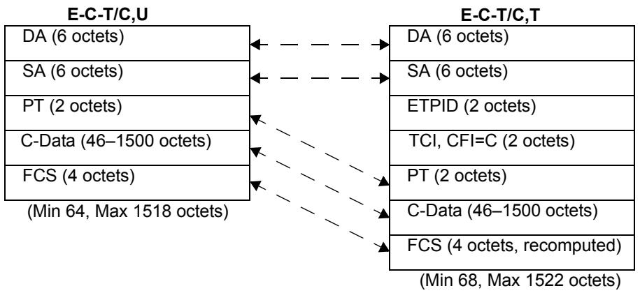
Figure C-7—Translation between E-C-T/C,U and E-C-T/C,T
The following translations are required in order to tag an E-C-T/C,U frame on IEEE 802.3/Ethernet:
a) The SA and DA fields are copied unchanged;
b) The ETPID and TCI are inserted, with CFI=C;
c) The PT and C-Data fields are copied unchanged;
d) The FCS is recomputed.
Removal of the tag involves the reverse of this process.
This form of tagging causes the original frame size to be increased by 4 octets.
Figure C-8 illustrates the translation between an untagged Ethernet Type-encoded frame on IEEE 802.3/Ethernet (E-C-T/C,U) and a tagged frame on Token Ring/FDDI (E-C-T/R,T).
The following translations are required in order to tag an E-C-T/C,U frame on a Token Ring/FDDI LAN:
e) The appropriate variant of the RCI field is added;
f) The DA and SA fields carry the same MAC Addresses as in the original frame;
NOTE—The meaning of the wording used in item f) (and in other instances in this annex where this form of words is used) is that the MAC Addresses in the original and translated frames, when represented using the hexadecimal notation defined in Clause 5 of IEEE Std 802, are the same.
g) The STPID and TCI are inserted, with CFI=C;
h) The PT is translated into the IEEE Std 802.1H, IETF RFC 1042, and IETF RFC 1390-encoded form (SPT);
i) The C-Data field is copied unchanged;
j) The FCS is recomputed.
Removal of the tag involves the reverse of this process.
This form of tagging causes the original frame size to be increased by 17 octets for FDDI or 18 octets for Token Ring.
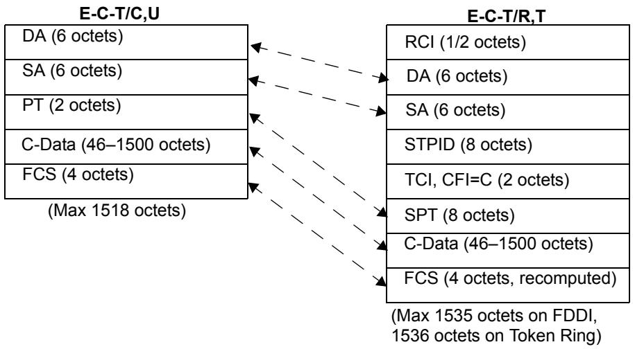
Figure C-8—Translation between E-C-T/C,U and E-C-T/R,T
NOTE—In translational (VLAN-unaware) bridging between IEEE 802.3/Ethernet and Ring LANs, an Ethernet Type-encoded frame increases in size by 7 octets on FDDI and 8 octets on Token Ring.
Translations for E-C-R/C,U, E-N-T/C,U, and E-N-R/C,U to their equivalent tagged frame formats (E-C-R/C,T, E-N-T/C,T, and E-N-R/C,T on IEEE 802.3/Ethernet, and E-C-R/R,T, E-N-T/R,T, and E-N-R/R,T on Token Ring/FDDI) cannot be shown, as there is no representation for such untagged frames on IEEE 802.3/Ethernet LANs. Similarly, translation of the tagged frames E-C-R/C,T, E-N-R/C,T, E-N-R/R,T, and E-C-R/R,T to untagged frames on IEEE 802.3/Ethernet is not possible, as it involves loss of the source-routing information. Translation of the remaining Non-canonical, transparent tagged frame formats into E-C-T/C,U is possible, but only if the Bridge is capable of translating Non-canonical data to its Canonical form.
C.5.1.2 LLC-encoded information on IEEE 802.3/Ethernet to tagged frame format
Figure C-9 illustrates the translation between an untagged frame on IEEE 802.3/Ethernet carrying LLC-encoded information (L-C-T/C,U) and a tagged frame on IEEE 802.3/Ethernet (L-C-T/C,T).
Tagging an L-C-T/C,U frame on IEEE 802.3/Ethernet LANs requires the following frame translations:
a) The DA and SA fields are copied unchanged;
b) Insert ETPID and TCI fields, with CFI=C;
c) Len, LLC and C-Data fields are copied unchanged;
d) The PAD may either be copied unchanged (giving a minimum tagged frame size of 68 octets), or reduced by up to 4 octets (giving a minimum tagged frame size of 64 octets), as an implementation option;
NOTE—If the actual length of the data portion of the frame is inconsistent with the value held in LEN, then this inconsistency is not corrected by the tagging process. This is done in order that protocols which generate such inconsistency, and which require that inconsistency to be maintained for their correct operation, are not broken by this aspect of tagging.
e) Recompute the FCS.
Removal of the tag involves the reverse of this process.
This form of tagging causes the original frame size to be increased by 4 octets.
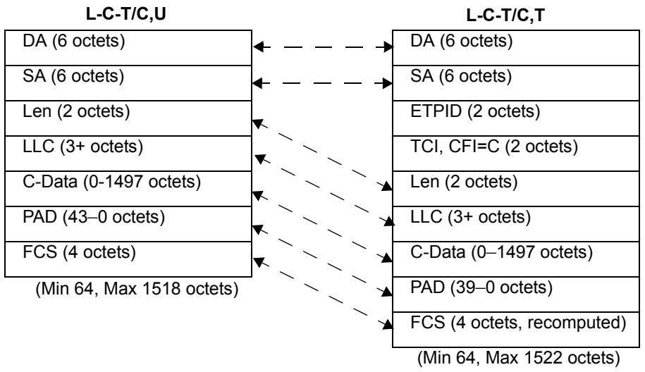
Figure C-9—Translation between L-C-T/C,U and L-C-T/C,T
Figure C-10 illustrates the translation between an untagged LLC-encoded frame on IEEE 802.3/Ethernet (L-C-T/C,U) and a tagged frame on Token Ring/FDDI (L-C-T/R,T).
Tagging in LLC-encoded format consists of the following frame translations:
f) The appropriate RCI field for the Ring MAC method concerned is added;
g) The DA and SA fields carry the same MAC Addresses as in the original frame;
h) Insert STPID and TCI fields, with CFI=C;
i) The Len field is removed;
j) Copy the LLC field unchanged;
k) The C-Data field is copied unchanged;
1) The PAD field is removed;
m) Recompute the FCS.
Removal of the tag (tagged frame to native IEEE 802.3/Ethernet frame) involves the reverse of this process.
This form of tagging causes the original frame size to be increased by 9 octets for FDDI or 10 octets for Token Ring.
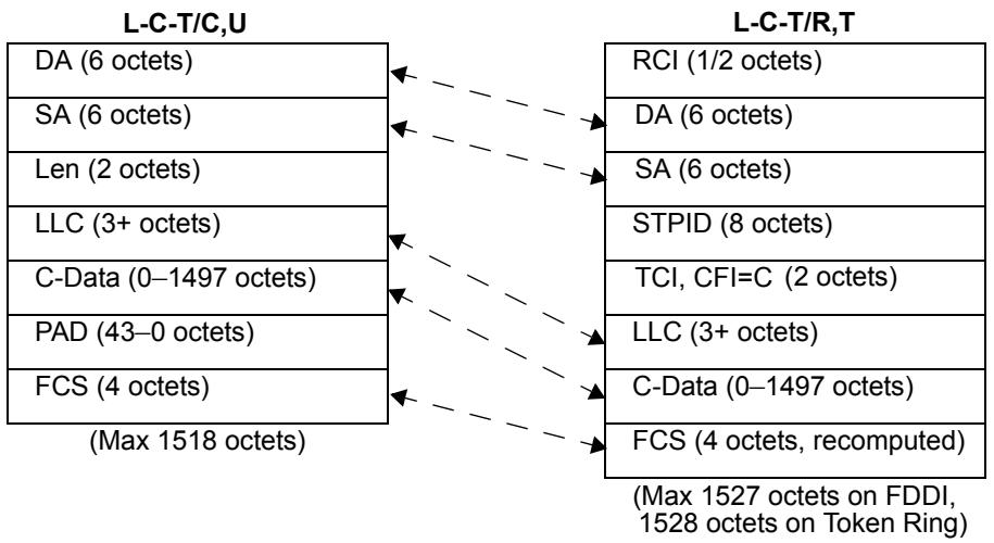
Figure C-10—Translation between L-C-T/C,U and L-C-T/R,T
NOTE—In translational (VLAN-unaware) bridging between IEEE 802.3/Ethernet and Ring LANs, an LLC-encoded frame reduces in size by 1 octet on FDDI and does not change in length on Token Ring.
Translations for L-C-R/C,U, L-N-T/C,U, and L-N-R/C,U to their equivalent tagged frame formats (L-C-R/C,T, L-N-T/C,T, and L-N-R/C,T on IEEE 802.3/Ethernet, and L-C-R/R,T, L-N-T/R,T, and L-N-R/R,T on Token Ring/FDDI) cannot be shown, as there is no representation for such untagged frames on IEEE 802.3/Ethernet LANs. Similarly, translation of L-C-R/C,T, L-N-R/C,T, L-N-R/R,T, and L-C-R/R,T to untagged frames on IEEE 802.3/Ethernet is not possible, as it involves loss of the source-routing information. Translation of the remaining Non-canonical, transparent tagged frame formats into L-C-T/C,U is possible, but only if the Bridge is capable of translating Non-canonical data to its Canonical form.
C.5.2 Translation of untagged Token Ring/FDDI frames
C.5.2.1 Ethernet Type-encoded information on Token Ring/FDDI to tagged frame format
Figure C-11 illustrates the translation between an untagged Ethernet Type-encoded frame on Token Ring/FDDI (E-C-T/R,U, E-N-T/R,U, E-C-R/R,U or E-N-R/R,U) and a tagged frame on IEEE 802.3/Ethernet (E-C-T/C,T, E-N-T/C,T, E-C-R/C,T, or E-N-R/C,T).
Tagging requires the following frame translations:
a) Remove the RCI field;
b) The DA and SA fields carry the same MAC Addresses as in the original frame, with the RII bit reset;
c) Insert ETPID and TCI, with CFI = C (E-C-T/R,U) or R (all other frame types);
d) If the RII bit was set in the original frame, translate the RIF into the tag header E-RIF. For E-N-T/R,U, create a RIF with frame type = transparent. Set the E-RIF NCFI to C or N appropriately;
e) Translate the SPT into its corresponding PT;
f) Copy the Data field;
g) Recompute the FCS.
Removal of the tag involves the reverse of this process.
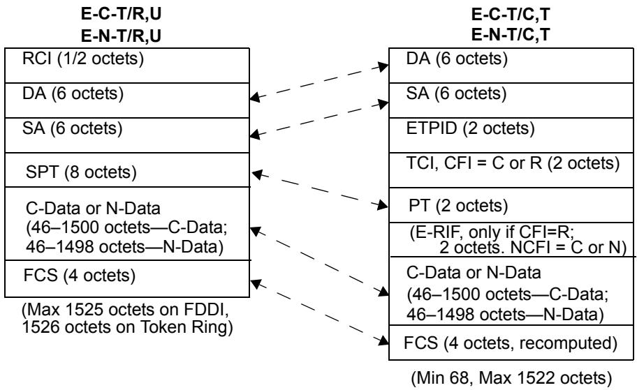
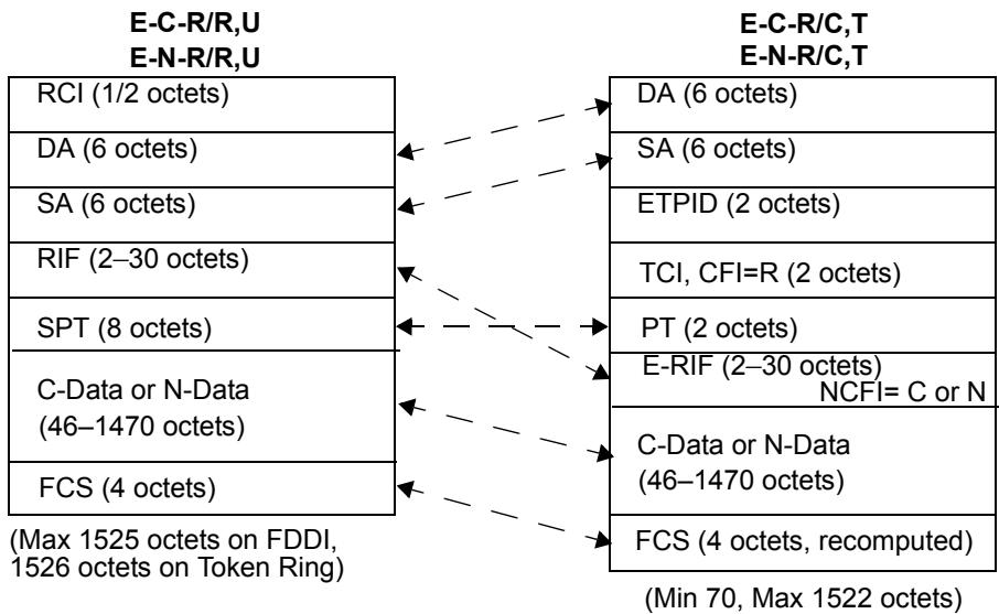
Figure C-11—Translation between E-X-X/R,U and E-X-X/C,T
NOTE 1—When removing the tag, if the CFI/NCFI indicates that embedded address information is in a form inappropriate for the destination MAC method, then it is necessary either to translate the address information or to discard the frame.
This form of tagging causes the original frame size to be reduced by 3 or 4 octets.
Figure C-12 illustrates the translation between an untagged Ethernet Type-encoded frame on Token Ring/FDDI (E-C-T/R,U, E-N-T/R,U, E-C-R/R,U, or E-N-R/R,U) and a tagged frame on 8802-5 Token Ring (E-C-T/R,T, E-N-T/R,T, E-C-R/R,T, or E-N-R/R,T). Figure C-12 also illustrates the translation of E-C-T/R,U, E-C-R/R,U, and E-N-R/R,U to tagged frames on FDDI media, the latter two translations illustrating the source-routed form of the tagged frame on FDDI.
Tagging requires the following frame translations:
h) Copy the RCI field;
i) The DA and SA fields carry the same MAC Addresses as in the original frame, with RII in the same state as in the original frame;
j) Copy the RIF field if present (RII set);
k) Insert STPID and TCI, setting the CFI to N or C appropriately;
1) Copy the SPT field;
m) Copy the Data field;
n) Recompute the FCS.
Removal of the tag (tagged frame to native Token Ring/FDDI frame) involves the reverse of this process.
NOTE 2—When removing the tag, if the CFI indicates that embedded address information is in a form inappropriate for the destination MAC method, then it is necessary either to translate the address information or to discard the frame.
This form of tagging causes the original frame size to be increased by 10 octets.
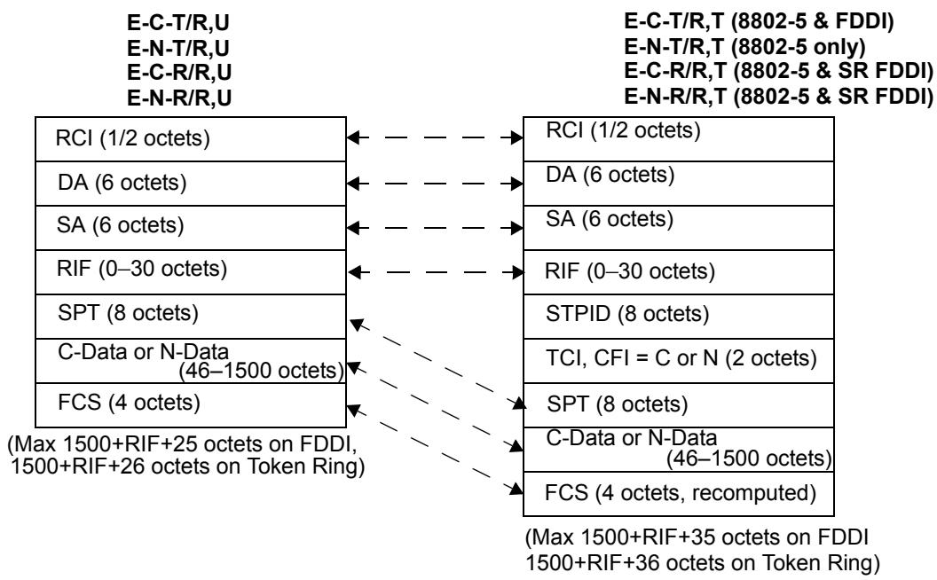
Figure C-12—Translation between E-X-X/R,U and E-X-X/R,T (8802-5 & SR FDDI)
Figure C-13 illustrates the translation between an untagged Ethernet Type-encoded frame on Token Ring/FDDI (E-N-T/R,U, E-C-R/R,U or E-N-R/R,U) and a tagged frame on FDDI (E-N-T/R,T, E-C-R/R,T or E-N-R/R,T). Note that the translation of E-C-T/R,U to E-C-T/R,T was dealt with in Figure C-12.
Tagging requires the following frame translations:
o) Copy the RCI field;
p) The DA and SA fields carry the same MAC Addresses as in the original frame, but with RII reset regardless of its state in the original frame;
q) Insert STPID and TCI, setting the CFI to R;
r) Translate the RIF field if present (RII set in source frame) to the E-RIF; otherwise, create an E-RIF with RT indicating a transparent frame. Set the NCFI to C or N appropriately;
s) Copy the SPT field;
t) Copy the Data field;
u) Recompute the FCS.
Removal of the tag (FDDI tagged frame to native Token Ring/FDDI frame) involves the reverse of this process.
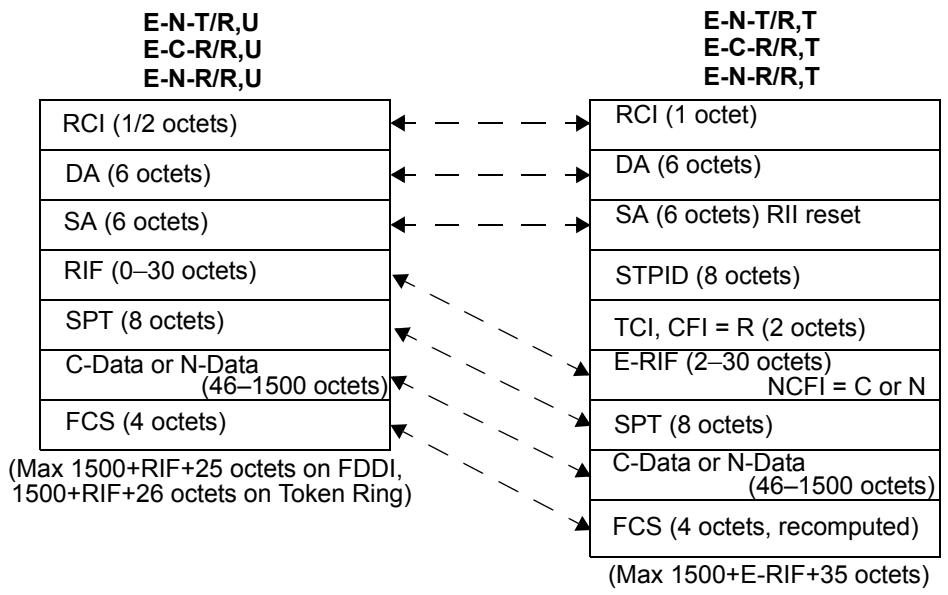
Figure C-13—Translation between E-X-X/R,U and E-X-X/R,T (transparent FDDI)
NOTE 3—When removing the tag, if the NCFI indicates that embedded address information is in a form inappropriate for the destination MAC method, then it is necessary either to translate the address information or to discard the frame.
This form of tagging causes the original frame size to be increased by 10 or 12 octets.
C.5.2.2 LLC-encoded information on Token Ring/FDDI to tagged frame format
Figure C-14 illustrates the translation between an untagged LLC-encoded frame on Token Ring/FDDI (L-C-T/R,U, L-N-T/R,U, L-C-R/R,U, or L-N-R/R,U) and a tagged frame on IEEE 802.3/Ethernet (L-C-T/C,T, L-N-T/C,T, L-C-R/C,T, or L-N-R/C,T).
Tagging requires the following frame translations:
a) Remove the RCI field;
b) The DA and SA fields carry the same MAC Addresses as in the original frame, with the RII bit reset;
c) Insert ETPID and TCI, with CFI = C (L-C-T/R,U) or R (all other frame types);
d) If the RII bit was set in the original frame, translate the RIF into the tag header E-RIF. For L-N-T/R,U, create an E-RIF with frame type = transparent. Set the E-RIF NCFI to C or N appropriately;
e) Insert the Len field, with value equal to the number of LLC+Data octets;
f) Copy the LLC field;
g) Copy the Data field;
h) PAD field is inserted if Len is less than 46 (if a minimum tagged frame size of 68 is implemented) or if less than 42 (if a minimum tagged frame size of 64 is implemented);
i) Recompute the FCS.
Removal of the tag involves the reverse of this process.
NOTE 1—When removing the tag, if the CFI/NCFI information indicates that embedded address information is in a form inappropriate for the destination MAC method, then it is necessary either to translate the address information or to discard the frame.
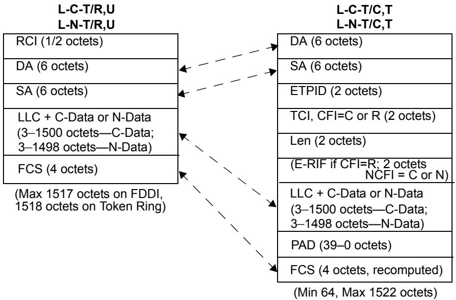
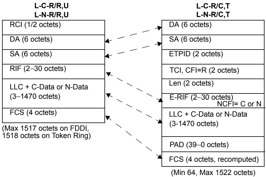
Figure C-14—Translation between L-X-X/R,U and L-X-X/C,T
This form of tagging causes the original frame size to be increased by 5 or 6 octets.
Figure C-15 illustrates the translation between an untagged LLC-encoded frame on Token Ring/FDDI (L-C-T/R,U, L-N-T/R,U, L-C-R/R,U, or L-N-R/R,U) and a tagged frame on 8802-5 Token Ring (L-C-T/R,T, L-N-T/R,T, L-C-R/R,T, or L-N-R/R,T). Figure C-15 also illustrates the translation of L-C-T/R,U, L-C-R/R,U, and L-N-R/R,U to tagged frames on FDDI media, the latter two translations illustrating the source-routed form of the tagged frame on FDDI.
Tagging requires the following frame translations:
j) Copy the RCI field;
k) The DA and SA fields carry the same MAC Addresses as in the original frame;
1) Copy the RIF field if present;
m) Insert STPID and TCI, setting the CFI to N or C appropriately;
n) Copy the LLC field;
o) Copy the Data field;
p) Recompute the FCS.
Removal of the tag (tagged frame to native Token Ring/FDDI frame) involves the reverse of this process.
NOTE 2—When removing the tag, if the CFI indicates that embedded address information is in a form inappropriate for the destination MAC method, then it is necessary either to translate the address information or to discard the frame.
This form of tagging causes the original frame size to be increased by 10 octets for FDDI and Token Ring.
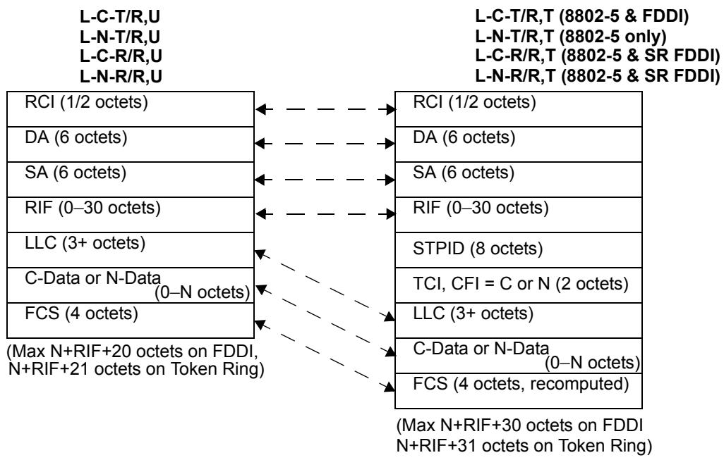
Figure C-15—Translation between L-X-X/R,U and L-X-X/R,T (8802-5 and SR FDDI)
Figure C-16 illustrates the translation between an untagged LLC-encoded frame on Token Ring/FDDI (L-N-T/R,U, L-C-R/R,U, or L-N-R/R,U) and a tagged frame on 8802-5 Token Ring (L-C-T/R,T, L-N-T/R,T, L-C-R/R,T, or L-N-R/R,T). Note that the translation of L-C-T/R,U to L-C-T/R,T was dealt with in Figure C-15.
Tagging requires the following frame translations:
q) Copy the RCI field;
r) The DA and SA fields carry the same MAC Addresses as in the original frame, but with RII reset regardless of its state in the original frame;
s) Insert STPID and TCI, setting the CFI to R;
t) Translate the RIF field if present (RII set in source frame) to the E-RIF; otherwise, create an E-RIF with RT indicating a transparent frame. Set the NCFI to C or N appropriately;
u) Copy the LLC field;
v) Copy the Data field;
w) Recompute the FCS.
Removal of the tag (tagged frame to native Token Ring/FDDI frame) involves the reverse of this process.
NOTE 3—When removing the tag, if the NCFI indicates that embedded address information is in a form inappropriate for the destination MAC method, then it is necessary either to translate the address information or to discard the frame.
This form of tagging causes the original frame size to be increased by 10 or 12 octets.
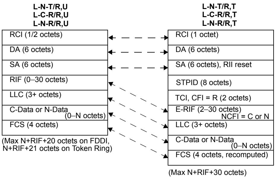
Figure C-16—Translation between L-X-X/R,U and L-X-X/R,T (transparent FDDI)
C.5.3 Translation of tagged frames during relaying
Subclauses C.5.3.1 through C.5.3.3 show the frame translations that can occur when a tagged frame is relayed from IEEE 802.3/Ethernet to Token Ring/FDDI and vice versa. The translations that occur between the transparent FDDI tagged frame format and the SR form on Token Ring/FDDI are also shown.
C.5.3.1 Tagged frames carrying Ethernet Type-encoded information
Figure C-17 illustrates the translation of tagged frames carrying Ethernet Type-encoded information between Token Ring/FDDI LANs and IEEE 802.3/Ethernet LANs.
Relaying Ethernet Type-encoded tagged frames from Token Ring/FDDI (SR form) to IEEE 802.3/Ethernet requires the following frame translations:
a) Remove the RCI field;
b) The DA and SA fields carry the same MAC Addresses as in the original frame, with the RII bit reset;
c) Replace the STPID with an ETPID;
d) The TCI field carries the same VID and Priority values as in the original frame (unless the relay function causes changes to PCP or VID values). For E-C-T/C,T, CFI = C; otherwise, CFI = R;
e) Convert the SPT field to a PT (IEEE Std 802.1H, IETF RFC 1042, and IETF RFC 1390 translation);
f) Copy the RIF, if present, into the tag header E-RIF. Create an E-RIF if the data type being carried is E-N-T/C,T. Set the NCFI in the E-RIF to C or N appropriately;
g) Copy the Data field;
h) Recompute the FCS.
Tagged frame on Token Ring/FDDI (SR form)
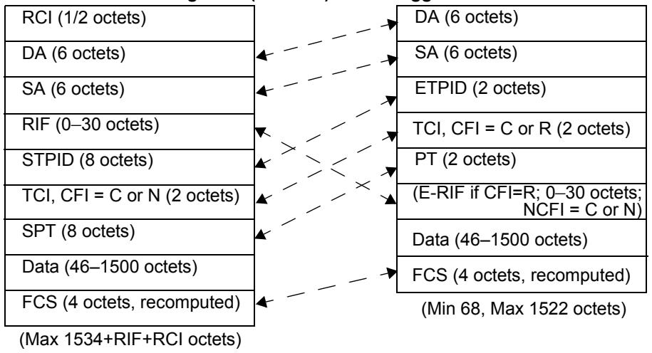
Tagged frame on 802.3/Ethernet
Tagged frame on FDDI (transparent form)
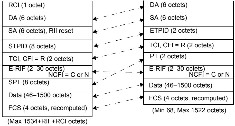
Tagged frame on 802.3/Ethernet
Figure C-17—Relaying Ethernet Type-encoded tagged frames
Relaying Ethernet Type-encoded tagged frames from FDDI (transparent form) to IEEE 802.3/Ethernet requires the following frame translations:
i) Remove the RCI field;
j) The DA and SA fields carry the same MAC Addresses as in the original frame, with the RII bit reset;
k) Replace the STPID with an ETPID;
1) The TCI field carries the same VID, Priority and CFI values as in the original frame (unless the relay function causes changes to PCP or VID values);
m) Convert the SPT field to a PT (IEEE Std 802.1H, IETF RFC 1042, and IETF RFC 1390 translation);
n) Copy the E-RIF;
o) Copy the Data field;
p) Recompute the FCS.
Relaying from IEEE 802.3/Ethernet to Token Ring/FDDI involves the reverse of these processes.
C.5.3.2 Tagged frames carrying LLC-encoded information
Figure C-18 illustrates the translation of tagged frames carrying LLC-encoded information between Token Ring/FDDI LANs and IEEE 802.3/Ethernet LANs.
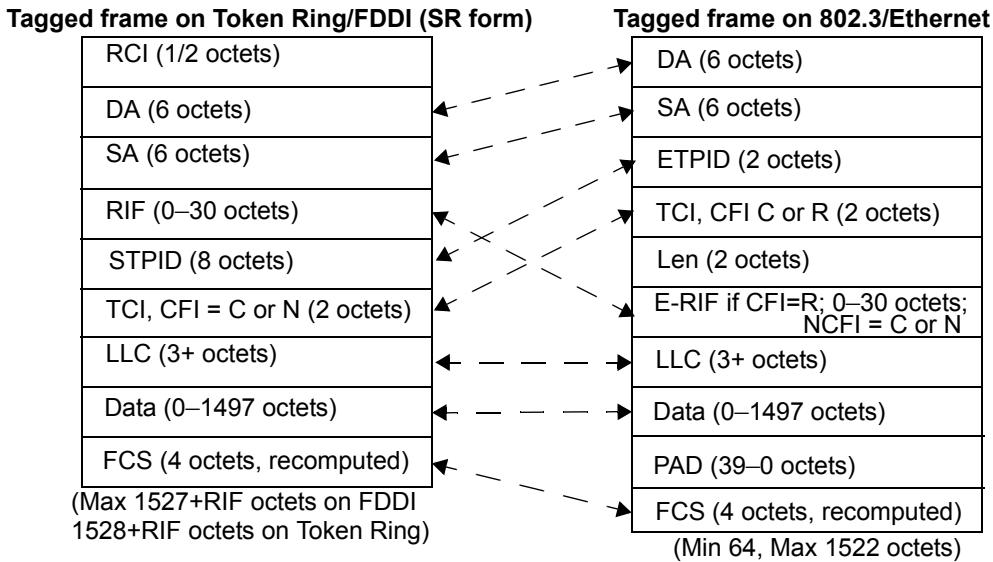
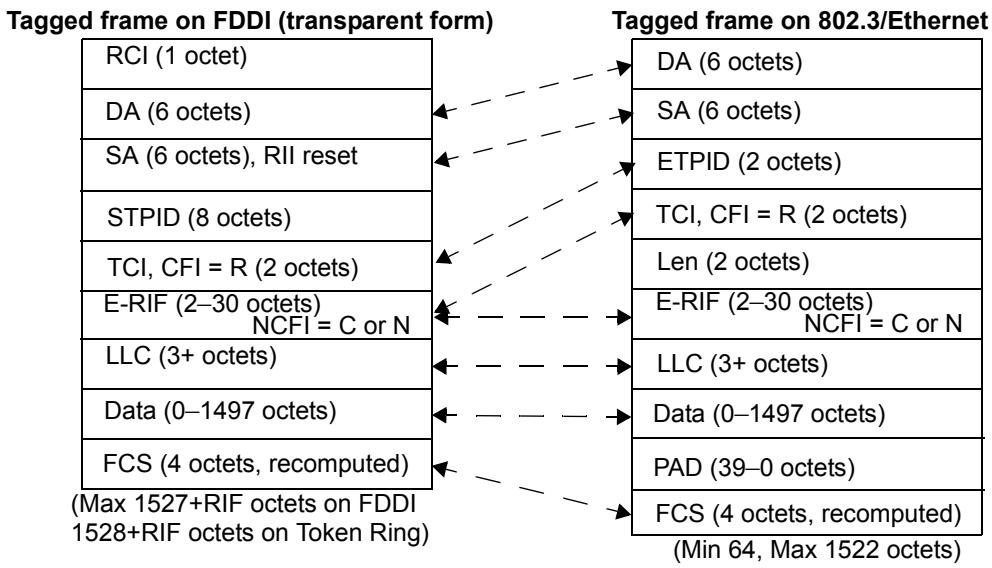
Figure C-18—Relaying LLC-encoded tagged frames
Relaying LLC-encoded frames in tagged format from Token Ring/FDDI (SR form) to IEEE 802.3/Ethernet requires the following frame translations:
a) Remove the RCI field;
b) The DA and SA fields carry the same MAC Addresses as in the original frame, with the RII bit reset;
c) Replace the STPID with an ETPID;
d) The TCI field carries the same VID and Priority values as in the original frame (unless the relay function causes changes to PCP or VID values). For L-C-T/C,T, the CFI = C; otherwise, CFI = R;
e) Insert a LEN field, equal to LLC+RIF (if present) +Data;
f) Copy the RIF, if present, into the tag header E-RIF. Create an E-RIF if the data type being carried is E-N-T/C,T. Set the NCFI bit to C or N appropriately;
g) Copy the LLC field;
h) Copy the Data field;
i) Recompute the FCS.
Relaying LLC-encoded frames in tagged format from FDDI (transparent form) to IEEE 802.3/Ethernet requires the following frame translations:
j) Remove the RCI field;
k) The DA and SA fields carry the same MAC Addresses as in the original frame, with the RII bit reset;
1) Replace the STPID with an ETPID;
m) The TCI field carries the same VID, Priority and CFI values as in the original frame (unless the relay function causes changes to PCP or VID values);
n) Insert a LEN field, equal to E-RIF + LLC +Data;
o) Copy the E-RIF;
p) Copy the LLC field;
q) Copy the Data field;
r) Recompute the FCS.
Relaying from IEEE 802.3/Ethernet to Token Ring/FDDI involves the reverse of these process.
C.5.3.3 Translation between transparent FDDI format and SR format
Figure C-19 illustrates the translation of tagged frames between transparent FDDI format and the corresponding SR format on Token Ring/FDDI LANs. The translation shown applies to X-N-T/R,T, X-C-R/R,T, and X-N-R/R,T frames only; other than translation of the RCI field, there is no translation required for X-C-T/R,T frames between Token Ring/FDDI LANs.
Relaying tagged frames from FDDI (transparent form) to Token Ring/FDDI (SR form) require the following frame translations:
a) Translate the RCI field;
b) The DA and SA fields carry the same MAC Addresses as in the original frame, with the RII bit set or reset to reflect the presence or absence of source-routing information in the E-RIF;
c) Translate source-routing information, if any, from the E-RIF form to the RIF, with the NCFI bit reset;
d) Copy the STPID;
e) The TCI field carries the same VID and Priority values as in the original frame (unless the relay function causes changes to PCP or VID values). The CFI is set to C or N to match the NCFI value in the E-RIF;
f) Copy the SPT or LLC field;
g) Copy the Data field;
h) Recompute the FCS.
Relaying from Token Ring/FDDI (SR form) to FDDI (transparent form) involves the reverse of these processes.
C.6 Field definitions
Subclauses C.6.1 through C.6.5 describe the field structures that correspond to some field names that appear in abbreviated form in the frame format diagrams in this standard.
Tagged frame on FDDI (transparent form) Tagged frame on Token Ring/FDDI (SR form)
<table><tr><td>RCI (1 octet)</td><td>← — — — →</td><td>RCI (1/2 octets)</td></tr><tr><td>DA (6 octets)</td><td>← — — — — →</td><td>DA (6 octets)</td></tr><tr><td>SA (6 octets), RII reset</td><td>← — — — — →</td><td>SA (6 octets)</td></tr><tr><td>STPID (8 octets)</td><td>← — — — — →</td><td>RIF (0–30 octets)</td></tr><tr><td>TCI, CFI = R (2 octets)</td><td>← — — — — →</td><td>STPID (8 octets)</td></tr><tr><td>E-RIF (2–30 octets)NCFI = C or N</td><td>← — — — — →</td><td>TCI, CFI = C or N (2 octets)</td></tr><tr><td>SPT (8 octets) orLLC (>=3 octets)</td><td>← — — — — →</td><td>SPT (8 octets) orLLC (>=3 octets)</td></tr><tr><td>Data (N octets)</td><td>← — — — — →</td><td>Data (N octets)</td></tr><tr><td>FCS (4 octets, recomputed)</td><td>← — — — — →</td><td>FCS (4 octets, recomputed)</td></tr></table>
NOTE—Applies to X-N-T/R,T, X-C-R/R,T, and X-N-R/R,T frames only.
Figure C-19—Relaying tagged frames between transparent and SR forms
NOTE—These fields are defined in other standards and are not part of the additional specification required for the tagged frame format. They are included here in order to simplify the frame descriptions that appear in this standard, not in order to redefine their structure.
C.6.1 SNAP-encoded Protocol Type
The SNAP-encoded Protocol Type is eight octets in length, encoded in SNAP format. It consists of the standard SNAP header in the first three octets, followed by a SNAP PID consisting of the 00-00-00 OUI, followed by the Ethernet Type value to be encoded, as shown in Figure C-20.
<table><tr><td>SNAP sap header(3 octets; AA-AA-03)</td></tr><tr><td>OUI(3 octets; 00-00-00)</td></tr><tr><td>Protocol Type(2 octets)</td></tr></table>
Figure C-20—SNAP-encoded Protocol Type format
C.6.2 Len
This is the IEEE Std 802.3 Length/Type field; for the Length interpretation, it may take any value that is less than or equal to 1500. Values that exceed 1535 are interpreted as Ethernet Types. Values that exceed 1500 but are less than 1535 are undefined.
C.6.3 C-Data and N-Data
This is the data field of the encapsulated frame:
a) N-Data refers to a data field that is carried in Canonical format regardless of the MAC method carrying the frame;
b) C-Data refers to a data field that is carried in Non-canonical format regardless of the MAC method carrying the frame.
C.6.4 RIF and E-RIF
The RIF is the Source-Routing Information Field, as defined in IEEE Std 802.1D, C.3.3.2. If the original (untagged) frame had a RIF, then the RIF field of the tagged frame takes its value.
The E-RIF is a modified form of the RIF that appears within the tag header in tagged frames on transparent LANs (IEEE 802.3/Ethernet and FDDI when used as a transparent LAN). The structure of the E-RIF is defined in 9.7.
C.6.5 PAD
Zero or more padding octets, as required in order for the minimum frame size to be at least 64 octets.
Annex D
(informative)
Background to VLANs
In IEEE Std 802.1Q, 2004 Edition, and in previous revisions of this standard, the text in this annex contained tutorial material that related the terminology and concepts introduced IEEE Std 802.1Q to the terminology and concepts that were current in the VLAN market at that time. As that material is now of only historical interest, and has no particular relevance to present-day usage, it has been removed.
This annex will be removed in the next revision of this standard.
Annex E
(informative)
Interoperability considerations
VLAN-aware Bridges that conform to this standard are able to interoperate in networks with other VLAN-aware Bridges. However, the VLAN-based filtering service defined in this standard, as provided in the context of a single spanning tree for the network, involves some constraints on the network topology and individual device configurations that differ from the set of constraints that apply to the building and configuration of networks based only on IEEE Std 802.1D.
In addition, VLAN-aware Bridges are able to interoperate with Bridges conformant with the IEEE Std 802.1D specification, as well as with both priority-aware and VLAN-aware end systems. Both the VLAN based filtering service and the tag insertion and removal service of IEEE Std 802.1Q cause constraints on intermixed network topologies and device configurations that again differ from the building and configuration of IEEE Std 802.1D standard networks.
The implications of certain device configurations may not be immediately apparent from the technical detail of this standard. In order to clarify the nature of the additional constraints, E.1 through E.6
a) Describe the basic requirements for interoperability;
b) Discuss those requirements in the context of homogeneous and heterogeneous configurations, with examples of some of the problems that can occur if these requirements are not adhered to.
E.1 Requirements for interoperability
Two primary aspects of the configuration of a network are of concern from the point of view of interoperability:
a) Establishing a consistent view of the static filtering configuration of Bridges in the network;
b) Ensuring that untagged frames are VLAN-tagged (and that the tag is subsequently removed) consistently regardless of Spanning Tree reconfigurations.
E.1.1 Static filtering requirements
Static filtering controls allow the network administrator to impose a level of control over the permitted connectivity in the network, by setting static MAC Address filters in the Filtering Databases of Bridges, and by controlling the extent of particular VLANs by manipulation of Static VLAN Registration Entries (8.8.2).
In order to ensure that end station-to-end station connectivity (or the lack of it) is consistent in all possible Spanning Tree configurations, any static filters need to be established taking account of the full mesh topology of the physical interconnections between Bridges in the network, not just the “normal” Spanning Tree topology to which the network is configured when all Bridges and LAN segments are operating correctly. An example of the consequences of failure to establish consistent controls for static VLAN filtering is given in E.2.1.
E.1.2 Configuration requirements for VLAN-tagging
IEEE 802.1Q Bridges classify incoming untagged frames by applying either a Port-based tagging rule on ingress that uses the PVID for the receiving Port as the VLAN classification for such frames or a Port-and-Protocol-based rule that uses the frame's upper layer protocol to select one of a port's VIDs. Maintaining consistent connectivity between any pair of end stations that are on the same VLAN, and where one or both of those end stations is VLAN-unaware, requires that
a) All VLAN-aware Bridge Ports that are connected to the same LAN segment apply a consistent set of ingress rules (8.6);
b) All VLAN-aware Bridge Ports that are connected to the same legacy region of a network apply a consistent set of ingress rules;
c) All VLAN-aware Bridge Ports that serve LAN segments to which members of the same VLAN are (or can be) attached apply a consistent set of ingress rules.
A legacy region of a network consists of any set of LAN segments that are physically interconnected via VLAN-unaware, IEEE 802.1D Bridges. A legacy region has the property that, by appropriate configuration of the Spanning Tree, a Spanning Tree path could be created between any pair of LAN segments in the region such that the path would pass only through VLAN-unaware Bridges.
NOTE—In case b), Spanning Tree reconfiguration within the legacy region can change the logical connectivity between the VLAN Ports and the LAN segments that they (directly or indirectly) serve. Hence, a Spanning Tree reconfiguration could result in any end stations connected to the legacy region being serviced via any VLAN-aware Port. In effect, such a reconfiguration reduces case b) to case a). Figure E-2 and Figure E-3 give examples of this type of configuration. In Figure E-2, the legacy region consists of all three LAN segments and both IEEE 802.1D Bridges. In Figure E-3, the legacy region consists of the IEEE 802.1D Bridge and both LAN segments to which it is attached. An example of case c) is where an end station attached to a leaf LAN segment is in the same VLAN as a server that is attached to a distinct LAN segment, i.e., all possible Spanning Tree paths between the two stations pass through a VLAN-aware region of the network.
The essence of what these rules express is that if a given untagged frame belongs on a given VLAN, then the classification and tagging behavior of any VLAN-aware Bridges that are required to tag that frame needs to be the same, regardless of the logical connectivity that is created by the Spanning Tree configuration of the network. Examples of the consequences of failure to apply these rules appear in E.3 and E.6.
E.2 Homogenous IEEE 802.1Q networks
This standard requires new considerations in building a network in which all Bridges are VLAN-aware. The arbitrary plug-and-play capability of IEEE Std 802.1D in creating a network topology is restricted when making use of the VLAN extensions defined in this standard.
E.2.1 Consistency of static VLAN filtering
In order for stations that are members of a given VLAN to be able to reach other members of the same VLAN elsewhere in the network, all Ports that are part of the Spanning Tree active topology (i.e., all Ports that are in a forwarding state) connecting the stations must be included in the member set (8.8.9) for the given VLAN. In order for this connectivity to be independent of any reconfiguration of the Spanning Tree topology, all paths among those stations, both forwarding and blocked, must have this characteristic. Use of management controls to manipulate the member set (e.g., filters for security) must be applied in a manner consistent with requirements of the full mesh topology of the network.
An inconsistency occurs, for example, if a VLAN is restricted from an active path, but not from a redundant path currently blocked by the operation of Spanning Tree. Should a Spanning Tree reconfiguration enable the previously blocked path, the restriction will no longer be in place. In the reverse, a Spanning Tree reconfiguration may suddenly impose a restriction that had not existed. A common use of such management restriction will likely arise from managers who make use of an “access” port construct. An access port may be a port that is absent from the member set (8.8.9) in all VLANs but the untagged, default VLAN. Should such an access port become the active connection between two portions of the network as a result of a Spanning Tree reconfiguration, all VLANs but that one will be partitioned at that point in the topology.
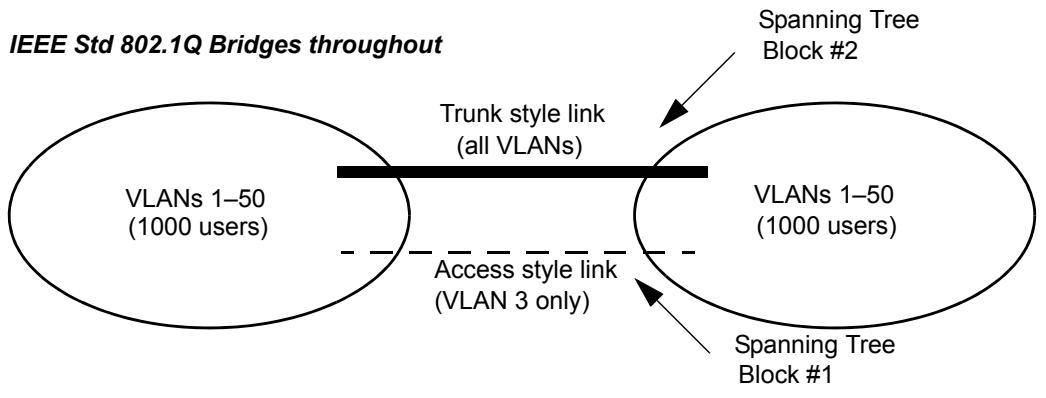
Figure E-1—Static filtering inconsistency
In Figure E-1, the trunk style link and access style link cause a loop through the left and right portions of the network. STP will block one or the other. Should the Spanning Tree block at point #1, all 2000 users may communicate on any of the 50 VLANs. However, should the Spanning Tree block at point #2, the left and right portions of the network will be partitioned on all VLANs excepting VLAN 3 (the VLAN carried via the access style link.)
E.2.2 Consistent view of the “untagged VLAN(s)” on a given LAN segment
In the Port-based VLAN model defined in this standard, the PVID for a Port provides the VLAN classification for all frames on the attached LAN segment that are received in untagged form. Any LAN segment with more than one IEEE 802.1Q Bridge attached has such an “untagged VLAN” for each Bridge. No explicit requirement that these be consistent for all Bridges on the same LAN segment, nor mechanism to assure such, has been included in this standard.
Similarly, in the Port-and-Protocol-based VLAN model defined in this standard, one member of the VID Set for a Port provides the VLAN classification for all frames on the attached LAN segment that are received in untagged form with a particular upper layer protocol. Any LAN segment with more than one such IEEE 802.1Q Bridge attached has such a set of “untagged VLANs” for each Bridge. No explicit requirement that these be consistent for all Bridges on the same LAN segment, nor mechanism to assure such, has been included in this standard.
Consider the case of a LAN segment to which are attached three VLAN-aware Bridges, each of which is using Port-based classification and is capable of transmission of untagged frames onto the LAN segment. An untagged frame placed on that segment by any one of the Bridges will be associated by each of the other two Bridges with its own configured PVID for its receiving port on that LAN. The IEEE 802.1Q VLAN model requires that each frame have a unique VLAN association, and that association is represented by a single, global VID value. Therefore, it follows that all IEEE 802.1Q Bridges on that LAN segment must make use of the same classification rules (in this case, the same PVID) for their ports connected to that LAN segment.
It has been suggested that in the special case of a direct point-to-point connection between two IEEE 802.1Q Bridges or other VLAN-aware devices, other rules might apply. No mechanism for identifying such links has yet been suggested.
This creates a configuration challenge for installers of Bridges that conform to this standard. Initial management configuration of the Bridges (the setting of PVIDs, VID Sets, and Protocol Group Databases) must be made consistent among the Bridges, in a manner that takes into account the actual physical topology. Changes to the physical topology may require specific changes to the configuration of all affected switches. These requirements effectively disallow a plug-and-play installation as supported by IEEE 802.1D Bridged Local Area Networks, unless all Bridges are left with their default Port-based classification rules and with each PVID = 1.
E.3 Heterogeneous networks: Intermixing IEEE 802.1D (D) and IEEE 802.1Q (Q) Bridges
This subclause discusses networks in which VLAN-aware Bridges that conform to this standard are intermixed with VLAN-unaware Bridges conformant to IEEE Std 802.1D.
A principal limitation in intermixing Q Bridges with D Bridges is that the VLAN filtering services are not universally available throughout the network. Also, services for the insertion and removal of tags are not universally available. Furthermore, spanning tree reconfigurations may cause filtering services, as well as tag insertion and removal services, to become available or become unavailable independent of actions of affected users.
E.3.1 Example: Adding an IEEE 802.1Q Bridge to provide filtering to an IEEE 802.1D network
Example problems can be shown with the following topology diagrams. Figure E-2 includes one Q Bridge and two D Bridges:
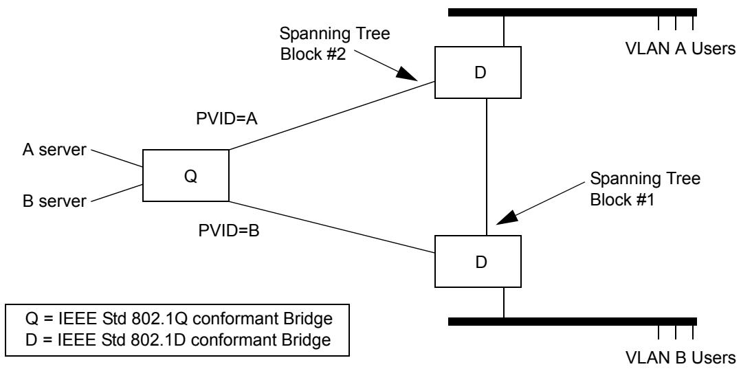
Figure E-2—Interoperability with IEEE 802.1D Bridges: example 1
If the Spanning Tree protocol determines to break the loop among the three Bridges by blocking at point #1, connectivity within each VLAN is as desired. However, should the block occur at point #2, traffic from VLAN A users will pass through both D Bridges and be treated as VLAN B traffic upon arrival in the Q Bridge. Connectivity to the A server will be lost for the A users.
E.3.2 Example: Adding an IEEE 802.1D Bridge to a (previously) Homogenous IEEE 802.1Q Network
A similar problem, demonstrating the impact of placing a D Bridge within an otherwise homogenous Q topology, can be shown by the configuration in Figure E-3. Here we include two Q Bridges and add a single redundant D Bridge:
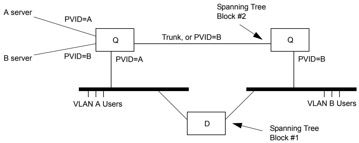
Figure E-3—Interoperability with IEEE 802.1D Bridges: example 2
If STP determines to break the loop among the three Bridges by blocking at point #1, connectivity within each VLAN is as desired. The two Q switches operate as expected. A and B VLAN frames are VLAN-tagged on arrival in either Q Bridge and forwarded only to the appropriate servers. Now suppose an STP reconfiguration results in a block at point #2, but not at #1. This redirects VLAN B user traffic through the IEEE 802.1D Bridge. VLAN B users no longer have their traffic identifiably distinct from VLAN A. An immediate consequence is that the VLAN B users will no longer have access to the “B server.”
E.4 Heterogeneous networks: Intermixing IEEE 802.1H and IEEE 802.1Q Bridges
Translating Bridges (i.e., Bridges that relay between Token Ring/FDDI and IEEE 802.3/Ethernet LANs) that implement the encapsulation techniques described in IEEE Std 802.1H, IETF RFC 1042, and IETF RFC 1390 can be intermixed with IEEE 802.1Q Bridges under certain limited conditions. In order to understand the limitations involved, it is necessary to describe what happens to the various tagged frame formats when passed through a Translating Bridge. The frame formats shown in E.4.1 through E.4.5 use the notation that is defined in Annex C.
NOTE—The examples shown are not exhaustive; in particular, the examples do not make use of the transparent tagged frame format on FDDI. However, the examples illustrate the nature of the problems that can occur with such translations.
E.4.1 LLC-encoded tagged frames relayed from IEEE 802.3/Ethernet to Token Ring or source-routed FDDI
A Transparent LLC-encoded frame on IEEE 802.3/Ethernet has the following form:
L-C-T/C,T: DA, SA, ETPID, TCI (CFI reset), LEN, LLC, C-Data, PAD, FCS
The Translating Bridge will recognize the ETPID as an Ethernet Type that requires translation into an SPT. This effectively translates the ETPID to an STPID. The translated frame, therefore, appears as follows:
RCI, DA, SA (RII reset), STPID, TCI (CFI reset), LEN, LLC, C-Data, PAD, FCS
Whereas a true translation of the tagged frame via an IEEE 802.1Q Bridge would result in
L-C-T/R,T: RCI, DA, SA (RII reset), STPID, TCI (CFI reset), LLC, C-Data, FCS
As can be seen, the resultant frame superficially appears to be a valid tagged frame; however, it includes spurious LEN and PAD fields and is therefore not a valid tagged frame.
A source-routed LLC-encoded frame on IEEE 802.3/Ethernet has the following form:
L-C-R/C,T: DA, SA, ETPID, TCI (CFI set), LEN, RIF (NCFI=C), LLC, C-Data, PAD, FCS
The Translating Bridge generates
RCI, DA, SA (RII reset), STPID, TCI (CFI set), LEN, RIF (NCFI=C), LLC, C-Data, PAD, FCS
Whereas a true translation of the tagged frame via an IEEE 802.1Q Bridge would result in
L-C-R/R,T: RCI, DA, SA (RII set), RIF, STPID, TCI (CFI reset), LLC, C-Data, FCS
Again, the resultant frame superficially appears to be a valid tagged frame; however, it includes spurious LEN, RIF, and PAD fields; the RIF information is not visible to any source routing Bridges attached to the Ring medium; and the CFI indicates Non-canonical data where the actual data are Canonical.
NOTE—Similar problems exist for the other two LLC-encoded formats, L-N-R and L-N-T, but the CFI correctly indicates Non-canonical data in the translated frame.
In both cases, the effect of the Translating Bridge is symmetrical; passing this invalid frame back through the Translating Bridge restores it to a valid tagged frame format on IEEE 802.3/Ethernet.
Consequently,
a) The translated frames cannot be correctly interpreted by VLAN-aware end stations attached to the Ring medium;
b) In both cases, any IEEE 802.1Q Bridge that attempts to untag the translated frames will generate invalid untagged frames;
c) Any IEEE 802.1Q Bridge that attempts to relay the translated frames back onto Token Ring/FDDI will generate invalid tagged frames;
d) In the case of the source-routed frame, any source routing Bridges attached to the Ring will treat the frame as a transparent frame;
e) As the effect of the Translating Bridge is symmetric, passing the frame through an even number of such translations before any IEEE 802.1Q device attempts to interpret the frame format results in correct operation of the IEEE 802.1Q devices.
E.4.2 Ethernet Type-encoded tagged frames relayed from IEEE 802.3/Ethernet to Token Ring or source-routed FDDI
A Transparent Ethernet Type-encoded frame on IEEE 802.3/Ethernet has the following form:
E-C-T/C,T: DA, SA, ETPID, TCI (CFI reset), PT, C-Data, FCS
The Translating Bridge generates:
RCI, DA, SA (RII reset), STPID, TCI (CFI reset), PT, C-Data, FCS
Whereas a true translation of the tagged frame via an IEEE 802.1Q Bridge would result in
E-C-T/R,T: RCI, DA, SA (RII reset), STPID, TCI (CFI reset), SPT, C-Data, FCS
The resultant frame is superficially a valid tagged frame but carries an untranslated Ethernet Type where there should be a SNAP-encoded Ethernet Type.
A source-routed Ethernet Type-encoded frame on IEEE 802.3/Ethernet has the following form:
E-C-R/C,T: DA, SA, ETPID, TCI (CFI set), PT, RIF (NCFI = C), C-Data, FCS
The Translating Bridge generates
RCI, DA, SA, STPID, TCI (CFI set), PT, RIF (NCFI = C), C-Data, FCS
Whereas a true translation of the tagged frame via an IEEE Std 802.1Q Bridge would result in
E-C-R/R,T: RCI, DA, SA (RII set), RIF, STPID, TCI (CFI reset), SPT, C-Data, FCS
Again, the resultant frame is superficially a valid tagged frame but carries an untranslated Ethernet Type where there should be a SNAP-encoded Ethernet Type and carries a spurious RIF field. The CFI is also incorrect.
NOTE—Similar problems exist for the other two Ethernet Type-encoded formats, E-N-R and E-N-T, but the CFI correctly indicates Non-canonical data in the translated frame.
In both cases, the effect of the Translating Bridge is symmetrical; passing this invalid frame back through the Translating Bridge restores it to a valid tagged frame format on IEEE 802.3/Ethernet.
Consequently,
a) The translated frames cannot be correctly interpreted by VLAN-aware end stations attached to the Ring medium;
b) Any IEEE 802.1Q Bridge that attempts to untag the translated frames will generate invalid untagged frames;
c) Any IEEE 802.1Q Bridge that attempts to relay the translated frames back onto Token Ring/FDDI will generate invalid tagged frames;
d) In the case of the source-routed frame, any source routing Bridges attached to the Ring will treat the frame as a transparent frame;
e) As the effect of the Translating Bridge is symmetric, passing the frame through an even number of such translations before any IEEE 802.1Q device attempts to interpret the frame format results in correct operation of the IEEE 802.1Q devices.
E.4.3 LLC-encoded tagged frames relayed from Token Ring or source-routed FDDI to IEEE 802.3/Ethernet
A Transparent LLC-encoded frame on Token Ring/FDDI has the following form:
L-C-T/R,T: RCI, DA, SA (RII reset), STPID, TCI (CFI reset), LLC, C-Data, FCS
The Translating Bridge generates
DA, SA, ETPID, TCI (CFI reset), LLC, C-Data, PAD, FCS
Whereas a true translation of the tagged frame via an IEEE 802.1Q Bridge would result in
L-C-T/C,T: DA, SA, ETPID, TCI (CFI reset), LEN, LLC, C-Data, PAD, FCS
As can be seen, the resultant frame superficially appears to be a valid tagged frame; however, it is missing the LEN field and is therefore not a valid tagged frame.
A source-routed LLC-encoded frame on Token Ring/FDDI has the following form:
L-C-R/R,T: RCI, DA, SA (RII set), RIF, STPID, TCI (CFI reset), LLC, C-Data, FCS
The Translating Bridge generates
DA, SA, ETPID, TCI (CFI reset), LLC, C-Data, PAD, FCS
Whereas a true translation of the tagged frame via an IEEE Std 802.1Q Bridge would result in
L-C-R/C,T: DA, SA, ETPID, TCI (CFI set), LEN, RIF (NCFI = C), LLC, C-Data, PAD, FCS
Again, the resultant frame superficially appears to be a valid tagged frame but is missing the LEN field. The RIF information has been lost.
Similar problems exist for the other two LLC-encoded formats, L-N-R and L-N-T, but in addition, the CFI will be set, indicating the presence of a RIF in the tag header when no such RIF field exists.
In both cases, the effect of the Translating Bridge is almost symmetrical; passing the invalid frame back through the Translating Bridge restores it to a valid tagged frame format on IEEE 802.3/Ethernet, but with the loss of any source-routing information that may have been present, and the inclusion of a PAD field if the original frame on the Ring medium had been small.
Consequently,
a) The translated frames cannot be correctly interpreted by VLAN-aware end stations attached to the Ring medium;
b) Any IEEE 802.1Q Bridge that attempts to untag the translated frames will generate invalid untagged frames;
c) Any IEEE 802.1Q Bridge that attempts to relay the translated frames back onto Token Ring/FDDI will generate invalid tagged frames;
d) Any source-routing information is lost;
e) As the effect of the Translating Bridge is almost symmetric (the RIF is lost, and there may be a PAD included), passing the frame through an even number of such translations before any IEEE 802.1Q device attempts to interpret the frame format results in correct operation of the IEEE 802.1Q devices, as long as those devices are not sensitive to the presence of spurious PAD information.
E.4.4 Ethernet Type-encoded tagged frames relayed from Token Ring or source-routed FDDI to IEEE 802.3/Ethernet
A Transparent Ethernet Type-encoded frame carrying Canonical data on Token Ring/FDDI has the following form:
E-C-T/R,T: RCI, DA, SA (RII reset), STPID, TCI (CFI reset), SPT, C-Data, FCS
The Translating Bridge generates
DA, SA, ETPID, TCI (CFI reset), SPT, C-Data, FCS
Whereas a true translation of the tagged frame via an IEEE Std 802.1Q Bridge would result in
E-C-T/C,T: DA, SA, ETPID, TCI (CFI reset), PT, C-Data, FCS
As can be seen, the resultant frame superficially appears to be a valid tagged frame; however, the SPT has not undergone translation to a PT. End stations encountering this frame on IEEE 802.3/Ethernet would only be capable of interpreting it if they were able to recognize the SPT as an embedded Ethernet Type.
Translating Canonical source-routed Ethernet Type-encoded information produces similar results, but with the additional loss of the source-routing information.
A Transparent Ethernet Type-encoded frame carrying Non-canonical information on Token Ring/FDDI has the following form:
E-N-T/R,T: RCI, DA, SA (RII reset), STPID, TCI (CFI set), SPT, N-Data, FCS
The Translating Bridge generates:
DA, SA, ETPID, TCI (CFI set), SPT, N-Data, FCS
Whereas a true translation of the tagged frame via an IEEE 802.1Q Bridge would result in:
E-N-T/C,T: DA, SA, ETPID, TCI (CFI set), PT, RIF (NCFI = N), N-Data, FCS
Again, the resultant frame superficially appears to be a valid tagged frame, but the SPT has not been translated to a PT, and the RIF is not present in the tag header. Any IEEE 802.1Q device will therefore interpret the first N octets of the N-Data field as if it was the RIF.
Translating Non-canonical source-routed Ethernet Type-encoded information produces similar results but with the additional loss of the source-routing information.
In both cases, the effect of the Translating Bridge is almost symmetrical; passing this invalid frame back through the Translating Bridge restores it to a valid tagged frame format on IEEE 802.3/Ethernet, but with the loss of any source-routing information that may have been present.
Consequently,
a) The translated frames cannot be correctly interpreted by VLAN-aware end stations attached to the Ring medium;
b) Any IEEE 802.1Q Bridge that attempts to untag translated frames carrying Non-canonical information will generate invalid untagged frames;
c) Any IEEE 802.1Q Bridge that attempts to relay untag translated frames carrying Non-canonical information back onto Token Ring/FDDI will generate invalid tagged frames;
d) Frames carrying Canonical information can be successfully untagged or relayed in tagged form using other MAC methods, as long as the IEEE 802.1Q Bridge is capable of correctly handling the embedded SPT;
e) Any source-routing information is lost;
f) As the effect of the Translating Bridge is symmetric (apart from the loss of RIF), passing the frame through an even number of such translations before any IEEE 802.1Q device attempts to interpret the frame format results in correct operation of the IEEE 802.1Q devices.
E.4.5 Conclusions
Except for the limited case of relaying Canonical Ethernet Type-encoded information from IEEE 802.3/Ethernet to Token Ring/FDDI, the translation that a tagged frame undergoes when passing through a Translating Bridge renders the frame uninterpretable by any IEEE 802.1Q device (either end station or Bridge), unless the frame has passed through an even number of Translating Bridges before the IEEE 802.1Q device attempts to interpret the frame. In regions where an odd number of translations have occurred, source-routing information is rendered invisible to source routing Bridges in some cases. In the other cases, source-routing information is lost after the first translation.
Consequently, the use of Translating Bridges intermixed with IEEE 802.1Q Bridges is feasible only if
a) An even number of translations (or zero translations) is experienced by any tagged frame that is transmitted between any pair of IEEE 802.1Q-aware devices in the network;
b) The loss of source routing capability across some regions of the network is acceptable, specifically, across regions where the first Translating Bridge encountered by a correctly formatted tagged frame will relay the frame from Token Ring/FDDI to IEEE 802.3/Ethernet;
c) End stations are not sensitive to receiving LLC-encoded frames that have PAD octets added to the LLC user data.
E.5 Heterogeneous networks: Intermixing IEEE 802.1Q Bridges with IEEE 802.1D Bridges
The specification in this standard for the use of GMRP in VLANs (10.2) makes use of VLAN-tagged frames to signal the GIP Context that applies to the registration information carried in GMRP PDUs. Devices that implement GMRP as specified in IEEE Std 802.1D will regard such frames as badly formed GMRP frames and will therefore discard them on receipt. Using an IEEE 802.1D Bridge to interconnect two or more LAN regions containing IEEE 802.1Q devices that implement GMRP will therefore prevent GMRP information propagation between the IEEE 802.1Q regions, with attendant effects upon the forwarding behavior of both the IEEE 802.1D and IEEE 802.1Q Bridges in the LAN. This configuration can be made to work if the IEEE 802.1D Bridge is statically configured with the following:
a) An All Groups entry in the Filtering Database, specifying Registration Fixed on all Ports, and
b) The GMRP Protocol Administrative Control parameters set to disable GMRP on all Ports.
As the Bridge no longer supports the GMRP application, it will forward GMRP PDUs on all Ports that are in Forwarding. The effect of this is to configure the IEEE 802.1D Bridge to behave in the same manner as an ISO/IEC 10038 Bridge.
Placing IEEE 802.1D Bridges around the periphery of an IEEE 802.1Q-based network works correctly, as long as, for a given IEEE 802.1D Bridge, the IEEE 802.1Q Bridges connected to the same segment(s) are configured to untag any VLANs that are relevant to the GMRP operation of the IEEE 802.1D Bridge. The IEEE 802.1D Bridge generates untagged GMRP frames, which the IEEE 802.1Q Bridges classify according to the value of the PVID for the reception Port; in a simple configuration of the IEEE 802.1Q Bridges, the Ports that connect to the IEEE 802.1D Bridge are configured for the PVID VLAN to be untagged on egress.
NOTE 1—There may be situations where more complex configurations are required, in which VLANs other than the PVID are configured untagged in order to maintain the correct IEEE 802.1D Bridge filtering behavior.
NOTE 2—For bridges that make VLAN assignments on untagged frames according to Port-and-Protocol-based classification rules, special care is necessary in configuration: since GMRP does not carry information about the particular protocol for which the Group membership is intended, it must be taken to apply to all protocols for which untagged traffic is carried on a particular link. Therefore, the VLAN indicated by a port's PVID is used to carry the GMRP frames associated with all of the VLANs which are members of the VID Set of that Port; in addition, the PVID must be configured to egress untagged on any other bridge port where any of the set of VIDs also egresses untagged and requires GMRP operation beyond that egress port.
The effect of this type of configuration is that all registrations propagated by a given IEEE 802.1D Bridge on a given (Port-based or Port-and-Protocol-based) VLAN are seen by all other IEEE 802.1D Bridges served by IEEE 802.1Q Bridges for which that VLAN is configured for untagged egress. The filtering behavior of the IEEE 802.1D Bridges is therefore governed only by the behavior of other devices (both IEEE 802.1D and IEEE 802.1Q) that are attached to the same VLAN.
E.6 Intermixing Port-based classification and Port-and-Protocol-based classification or future enhancements in IEEE Std 802.1Q
The discussion in E.5 on intermixing Q Bridges with D Bridges has a direct analogue in the mixing of bridges implementing only Port-based and Port-and-Protocol-based classification of frames in IEEE 802.1Q networks. This revision and potential subsequent editions of IEEE Std 802.1Q extend the VLAN classification capabilities to support more sophisticated ingress rules for frame classification.
In VLAN configurations that use both Port-based and Port-and-Protocol-based VLAN classification, a Bridge that supports only Port-based VLAN classification will merge VLANs that would otherwise be classified separately by a Bridge that supports Port-and-Protocol-based VLAN classification. To get around this problem, it may be possible to dedicate specific Ports to specific protocols in Bridges that support only Port-based VLAN classification, as in the example shown in Figure E-4. However, such solutions may not be possible where there are multiprotocol end stations in the network.
E.6.1 Example: Intermixing Protocol-based ingress rules
Consider the case where Bridges implement a configuration mechanism to select between Port-based classification rules (a “Q-Port Bridge”) and Port-and-Protocol-based rules (a “Q-Port/Protocol Bridge”). This case would allow, for example, for support for IP and IPX as distinct VLANs. The topology shown in Figure E-4 might apply when a Q-Port/Protocol Bridge is added to a topology; otherwise, using only Q-Port bridges allows users of two protocols to participate in two separate VLANs.
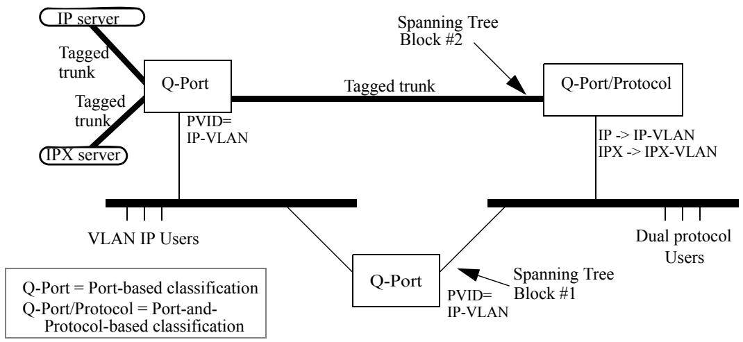
Figure E-4—Interoperability between Port-based and Port-and-Protocol-based classification
Consider this network, when STP has blocked at point #1, and not at #2. The upper Q-Port Bridge operates as expected, and the Q-Port/Protocol Bridge provides Port-and-Protocol-based classification for the frames received from the dual protocol users on the right-hand segment. IP-VLAN and IPX-VLAN frames are VLAN-tagged on the trunks to and from the uppermost Bridges and servers. But if a STP reconfiguration should result in a block at point #2, but not at #1, activating traffic through the lower Q-Port Bridge, dual protocol users will have all their traffic treated as part of the IP-VLAN. An immediate consequence is that the uppermost Bridge will no longer provide them access to the “IPX server.” It is the fact that the lower Q-Port Bridge must have just one of the two VLANs configured for all untagged traffic, regardless of its protocol, that leads to this lack of connectivity.
E.6.2 Differing views of untagged traffic on a given LAN segment
Further challenges arise when one considers the case where several Q Bridges, some implementing Port-based and some implementing Port-and-Protocol-based classification, all attach to the same LAN segment. Again, the rule that any given frame exists in exactly one VLAN requires that all of these Bridges be configured with consistent ingress rules. In this case, the Q-Port Bridges will provide a least common capability, and this further requires common configuration of the PVID in the Q-Port and Q-Port/Protocol Bridges.
Annex F
(informative)
Frame translation considerations
In IEEE Std 802.1Q, 2004 Edition, and in previous revisions of this standard, this annex discussed considerations relevant to Bridged Local Area Network environments where it might be necessary for a Bridge to translate frames between Ethernet and Token Ring or FDDI LANs. As this material is now of only historical interest, it has been removed.
This annex will be removed in the next revision of this standard.
Annex G
(informative)
Priority
This standard allows priorities, flow metering, queue assignment, and queue service disciplines to be managed to best support the goals of network administrators. This annex documents the rationale for the recommended and default priority to traffic class mappings in Table 8-2.
Classification of user data frames into a small number of behavior aggregates, together with aggregate dependent forwarding behavior in each Bridge, allows signaling of application requirements to the network. Frame classification, aggregate bandwidth metering, and policing also facilitate network scaling and provision of services to independent customers through allocation of those functions to appropriate Bridges in the network.
While there are many possible ways to classify frames and to specify forwarding behaviors, it is widely appreciated that a set of well-known and easily understood defaults can facilitate interoperability and the deployment of services. The defaults described in this annex and supported by this standard were chosen to support integrated and differentiated services, to minimize the burden of management, to reduce the possibility of misconfiguration and out-of-order frame delivery, and to provide useful service without management in many networks.
This standard mandates support for strict priority frame transmission (8.6.6) but permits the use of additional traffic class-based transmission selection algorithms. The default assignments of frames to traffic classes on the basis of frame priority, as described in this annex, also support the use of frame priority to select general traffic class-based forwarding behavior.
NOTE — Annex H provides references to the IETF work on integrated and differentiated services ([B3] through [B7] and [B11] through [B17]).
G.1 Traffic types
A full description of the QoS needs of applications and network services is too complex to be represented by a simple number 0 through 7. The pragmatic aim of traffic classification is to simplify requirements to preserve the high-speed, low-cost characteristics of Bridges. At the margin, potential bandwidth efficiency is traded for simplicity and higher speed operation—historically a good decision in the LAN.
The following list of traffic types, each of which can benefit from simple segregation from the others, are of general interest:
a) Network Control—characterized by a guaranteed delivery requirement to support configuration an maintenance of the network infrastructure.
b) Internetwork Control—in large networks comprising separate administrative domains there is typically a requirement to distinguish traffic supporting the network as a concatenation of those domains from the Network Control of the immediate domain.
c) Voice—characterized by less than 10 ms delay and, hence, maximum jitter (one way transmission through the LAN infrastructure of a single campus).
d) Video—characterized by less than 100 ms delay, or other applications with low latency as the primary QoS requirement.
e) Critical Applications—characterized by having a guaranteed minimum bandwidth as their primary QoS requirement and subject to some form of admission control to ensure that one system or application does not consume bandwidth at the expense of others. The admission control mechanism can range from pre-planning of the network requirement at one extreme to bandwidth reservation per flow at the time the flow is started at the other.
f) Excellent Effort—or “CEO’s best effort,” the best-effort type services that an information services organization would deliver to its most important customers.
g) Best Effort—for default use by unprioritized applications with fairness only regulated by the effects of TCP’s dynamic windowing and retransmission strategy.
h) Background—bulk transfers and other activities that are permitted on the network but that should not impact the use of the network by other users and applications.
G.2 Managing latency and throughput
Use of priorities and queuing by traffic classes, each class encompassing one or more priorities, facilitates improvement and management of latency and throughput, allowing QoS goals to be supported at higher levels of network loading than would otherwise be possible.
Congestion, resulting in QoS degradation, is not equally likely at all Bridges in a network. Transient traffic patterns are likely to result in congestion in only a few Bridges at a time, while over an extended period, momentary congestion is more likely to occur in the network core than at Bridge Ports attached to one or a relatively small number of end stations. Use of fewer traffic classes for those Ports can lower the cost of implementation and management, and this standard facilitates the use of Bridges supporting differing numbers of classes within a single network that delivers a consistent set of QoS parameters for each frame priority level. Although the number of traffic classes supported by each Bridge Port along the path taken by a given flow of data can vary, the default mappings of priorities to classes ensures that frame ordering is preserved as required by 8.6.6.
With few classes, the focus is on meeting latency requirements—the bandwidth surplus required in a bursty data environment to guarantee sub-10 ms delays without a distinct traffic classification is uneconomically large. As the number of traffic classes that can be used increases, the focus shifts to managing throughput.
The simple default queue servicing policy defined in this standard, strict priority, supports latency management. Active management of bandwidth sharing necessarily requires some management.
G.3 Traffic type to traffic class mapping
Table G-1 groups the traffic types introduced to match the number of traffic class queues supported by a Bridge Port. Each grouping of types is shown as $\{Distinguishing\ type, Type, Type, \ldots\}$ . The “distinguishing type” is not treated in any way differently in a Bridge but is italicized here to illustrate, for any given number of queues, which traffic types have driven the allocation of types to classes.
Table G-1—Traffic type to traffic class mapping
<table><tr><td>Number of queues</td><td>Traffic types</td></tr><tr><td>1</td><td>{Best Effort, Background, Excellent effort, Critical Applications, Voice, Video, Internetwork Control, Network Control}</td></tr><tr><td>2</td><td>{Best Effort, Background, Excellent effort, Critical Applications}{Voice, Video, Internetwork Control, Network Control}</td></tr><tr><td>3</td><td>{Best Effort, Background, Excellent effort, Critical Applications}{Voice, Video}{Network Control, Internetwork Control}</td></tr><tr><td>4</td><td>{Best Effort, Background}{Critical Applications, Excellent effort}{Voice, Video}{Network Control, Internetwork Control}</td></tr><tr><td>5</td><td>{Best Effort, Background}{Critical Applications, Excellent effort}{Voice, Video}{Internetwork Control}{Network Control}</td></tr><tr><td>6</td><td>{Background}{Best Effort}{Critical Applications, Excellent effort}{Voice, Video}{Internetwork Control}{Network Control}</td></tr><tr><td>7</td><td>{Background}{Best Effort}{Excellent effort}{Critical Applications}{Voice, Video}{Internetwork Control}{Network Control}</td></tr><tr><td>8</td><td>{Background}{Best Effort}{Excellent effort}{Critical Applications}{Video}{Voice}{Internetwork Control}{Network Control}</td></tr></table>
The step-by-step breaking out of traffic types as more classes are available proceeds as follows:
a) With a single queue, there are no choices. All traffic is Best Effort.
b) To support integrated services in the presence of bursty best effort data, it is necessary to segregate all time-critical traffic. The amount of high-priority traffic will be restricted by the need to support low latency for Voice, which becomes the defining type for the additional queue.
c) Two queues may be adequate for Bridge Ports attaching to end stations. The stability of the network as a whole may be unaffected by the performance of configuration protocols on those Ports, and in-band management of the Bridge is likely to occur through another Port. For Bridges within the network infrastructure, a further queue is used to isolate Network Control from the user data traffic.
d) Traffic for business Critical Applications is separated from Best Effort to allow a bandwidth guarantee to be provided.
e) The queue separation so far provided can support a large network. The next queue is allocated to distinguishing Internetwork Control traffic from local Network Control.
f) Background is separated from Best Effort to minimize the effect of bulk transfers on ordinary network use.
g) Excellent Effort is separated from Critical Applications, either to provide a simple superior service based on policy controlled access or to provide an additional segregated bandwidth guarantee.
h) The final provides increased network utilization as the higher bandwidth traffic associated with Video is no longer given the same latency guarantee as Voice.
This description is illustrative rather than definitive of the logic of allocating traffic types to classes. The mappings in Table 8-2 support the assignment of other semantics to each traffic type identified by priority values, e.g., the identification of all three illustrative types “Video,” “Critical Applications,” and “Excellent Effort” with assured forwarding classes that provide segregated bandwidth guarantees. However, alternate semantics should take into account the service provided by Bridges with limited traffic class queuing; e.g., of the foregoing, only “Video” would receive priority treatment by default at a Bridge Port supporting queuing for only two classes.
G.4 Traffic types and priority values
Table G-2 shows the correspondence between traffic types and priority values used to select the defaults in Table 8-2. The default priority used for transmission by end stations is 0. Changing this default would result in confusion and likely in interoperability problems. At the same time, the default traffic type is definitely Best Effort. 0 is thus used both for default priority and for Best Effort, and Background is associated with a priority value of 1. This means that the value 1 effectively communicates a lower priority than 0.
Table G-2—Traffic type acronyms
<table><tr><td>priority</td><td>Acronym</td><td>Traffic type</td></tr><tr><td>1</td><td>BK</td><td>Background</td></tr><tr><td>0 (Default)</td><td>BE</td><td>Best Effort</td></tr><tr><td>2</td><td>EE</td><td>Excellent Effort</td></tr><tr><td>3</td><td>CA</td><td>Critical Applications</td></tr><tr><td>4</td><td>VI</td><td>“Video,” < 100 ms latency and jitter</td></tr><tr><td>5</td><td>VO</td><td>“Voice,” < 10 ms latency and jitter</td></tr><tr><td>6</td><td>IC</td><td>Internetwork Control</td></tr><tr><td>7</td><td>NC</td><td>Network Control</td></tr></table>
Table G-3 summarizes Table G-1, showing just the defining traffic types. By maintaining the groupings of types established for a given number of queues for all less numbers, the table preserves the order of frames of any given type, independent of the number of queues.
This discussion of traffic types, and the suggested association of each with a priority value, differs from the similar discussion in Annex G of IEEE Std 802.1D-2004 and prior revisions of that standard. The latter was developed contemporaneously with IETF Intserv and predates Diffserv. The discussion in this annex better aligns with current practice; in particular, Voice is associated with priority 5, matching the setting of the relevant bits for Expedited Forwarding (EF) in the DSCP (Differentiated Services Code Point) for IP and in the common use of the EXP bits for MPLS. Standards for DSCPs are believed to be the prime reference for use of priority by end stations, and there is no direct change to the behavior of Bridge implementations conforming to this standard as a result of this change.
Table G-3—Defining traffic types
<table><tr><td>Number of queues</td><td colspan="8">Defining traffic type</td></tr><tr><td>1</td><td colspan="8">BE</td></tr><tr><td>2</td><td colspan="4">VO</td><td colspan="4">BE</td></tr><tr><td>3</td><td colspan="2">NC</td><td colspan="2">VO</td><td colspan="4">BE</td></tr><tr><td>4</td><td colspan="2">NC</td><td colspan="2">VO</td><td colspan="2">CA</td><td colspan="2">BE</td></tr><tr><td>5</td><td>NC</td><td>IC</td><td colspan="2">VO</td><td colspan="2">CA</td><td colspan="2">BE</td></tr><tr><td>6</td><td>NC</td><td>IC</td><td colspan="2">VO</td><td colspan="2">CA</td><td>BE</td><td>BK</td></tr><tr><td>7</td><td>NC</td><td>IC</td><td colspan="2">VO</td><td>CA</td><td>EE</td><td>BE</td><td>BK</td></tr><tr><td>8</td><td>NC</td><td>IC</td><td>VO</td><td>VI</td><td>CA</td><td>EE</td><td>BE</td><td>BK</td></tr></table>
The priority to traffic class mappings in Table 8-2 differ in one minor respect from those specified in prior revisions of this standard and in IEEE Std 802.1D-2004 and its prior revisions. Priority value 2 was previously described as ‘Spare’ and positioned lower than 0 (Best Effort) in priority order. This change may result in networks, including bridges, conformant to prior revisions of this standard, and implementing four or more traffic classes, providing less-than-expected priority to traffic described in this annex as Excellent Effort. The change allows better use of the available traffic classes given the low demand for two distinct priorities of lesser importance than Best Effort.
Annex H
(informative)
Bibliography
[B1] IEEE 100, The Authoritative Dictionary of IEEE Standards Terms, Seventh Edition, New York, Institute of Electrical and Electronics Engineers, Inc. $^{22}$
[B2] IEEE Std 802.3ad, IEEE Standard for Information Technology—Local and Metropolitan Area Networks—Part 3: Carrier Sense Multiple Access with Collision Detection (CSMA/CD) Access Method and Physical Layer Specifications—Aggregation of Multiple Link Segments.
[B3] IETF RFC 1633 (June 1994), Integrated Services in the Internet Architecture: An Overview, Braden, R., Clark, D., and Shenker, S. $^{23}$
[B4] IETF RFC 2205 (Sept. 1997), Resource Reservation Protocol (RSVP)—Version 1 Functional Specification, Braden, R., Zhang, L., Berson, S., Herzog, S. and Jamin, S.
[B5] IETF RFC 2211 (Sept. 1997), Specification of the Controlled-Load Network Element Service, Wroclawski, J.
[B6] IETF RFC 2212 (Sept. 1997), Specification of Guaranteed Quality of Service, Schenker, S., Partridge, C., and Guerin, R.
[B7] IETF RFC 2215 (Sept. 1997), General Characterization Parameters for Integrated Service Network Elements, Shenker, S., and Wroclawski, J.
[B8] IETF RFC 2210 (Sept. 1997), The Use of RSVP with IETF Integrated Services, Wroclawski, J.
[B9] IETF RFC 2233 (Nov. 1997), The Interfaces Group MIB using SMIv2, McCloghrie, K., and Kastenholz, F.
[B10] IETF RFC 2309 (Apr. 1998), Recommendations on Queue Management and Congestion Avoidance in the Internet, Braden, R., Clark, D., Crowcroft, J., Davie, B., Deering, S., Estrin, D., Floyd, S., Jacobson, V., Minshall, G., Partridge, C., Peterson, L., Ramakrishnan, K., Shenker, S., Wroclawski, J., and Zhang, L.
[B11] IETF RFC 2475 (Dec. 1998), An Architecture for Differentiated Services, Blake, S., Black, D., Carlson, M., Davies, E., Wang, Z., and Weiss, W.
[B12] IETF RFC 2597 (June 1999), Assured Forwarding PHB Group, Heinanen, J., Baker, F., Weiss, W., and Wroclawski, J.
[B13] IETF RFC 2814 (May 2000), SBM (Subnet Bandwidth Manager): A Protocol for Admission Control over IEEE 802-style Networks, Yavatkar, R., Hoffman, D., Bernet, Y., Baker, F., and Speer, M.
[B14] IETF RFC 2815 (May 2000), Integrated Service Mappings on IEEE 802 Networks, Seaman, M., Smith, A., Crawley, E., and Wroclawski, J.
[B15] IETF RFC 2816 (May 2000), A Framework for Providing Integrated Services Over Shared and Switched LAN Technologies, Ghanwani, A., Pace, W., Srinivasan, V., Smith, A., and Seaman, M.
[B16] IETF RFC 3246 (Mar. 2002), An Expedited Forwarding PHB (Per-Hop Behavior), Davie, B., Charny, A., Baker, F., Bennet, J., Benson, K., Boudec, J., Chiu, A., Courtney, W., Davari, S., Firoiu, V., Kalmanek, C., Ramakrishnam, K., and Stiliadis, D.
[B17] IETF RFC 3270 (May 2002), Multi-Protocol Label Switching (MPLS) Support of Differentiated Services, Le Faucheur, F., Wu, L., Davie, B., Davari, S., Vaananen, P., Krishnan, R., Cheval, P., and Heinanen, J.
[B18] ISO/IEC TR 11802-1:1997, Information Technology—Telecommunications and Information Exchange Between Systems—Local and Metropolitan Area Networks—Technical Reports and Guidelines—Part 1. The Structure and Coding of Logical Link Control Addresses in Local Area Networks.