802.1CB
IEEE Standard for
Local and metropolitan area networks—
Frame Replication and Elimination for Reliability
IEEE Computer Society
Sponsored by the
LAN/MAN Standards Committee
IEEE
3 Park Avenue
New York, NY 10016-5997
USA
IEEE Std 802.1CB™-2017
IEEE Standard for
Local and metropolitan area networks—
Frame Replication and Elimination for Reliability
Sponsor
LAN/MAN Standards Committee
of the
IEEE Computer Society
Approved 28 September 2017
IEEE-SA Standards Board
Abstract: This standard specifies procedures, managed objects, and protocols for bridges and end systems that provide identification and replication of packets for redundant transmission, identification of duplicate packets, and elimination of duplicate packets. It is not concerned with the creation of the multiple paths over which the duplicates are transmitted.
Keywords: Bridged Local Area Networks, Bridges, Bridging, Frame Elimination, Frame Replication, IEEE 802®, IEEE 802.1CB™, IEEE 802.1Q™, local area networks (LANs), MAC Bridges, Redundancy, Time-Sensitive Networking, TSN, Virtual Bridged Local Area Networks (virtual LANs)
The Institute of Electrical and Electronics Engineers, Inc. 3 Park Avenue, New York, NY 10016-5997, USA
Copyright © 2017 by The Institute of Electrical and Electronics Engineers, Inc. All rights reserved. Published 27 October 2017. Printed in the United States of America.
IEEE and 802 are registered trademarks in the U.S. Patent & Trademark Office, owned by The Institute of Electrical and Electronics Engineers, Incorporated.
Print: ISBN 978-1-5044-4297-8 STD22761 PDF: ISBN 978-1-5044-4298-5 STDPD22761
IEEE prohibits discrimination, harassment, and bullying. For more information, visit http://www.ieee.org/web/aboutus/whatis/policies/p9-26.html. No part of this publication may be reproduced in any form, in an electronic retrieval system or otherwise, without the prior written permission of the publisher.
Important Notices and Disclaimers Concerning IEEE Standards Documents
IEEE documents are made available for use subject to important notices and legal disclaimers. These notices and disclaimers, or a reference to this page, appear in all standards and may be found under the heading “Important Notices and Disclaimers Concerning IEEE Standards Documents.” They can also be obtained on request from IEEE or viewed at http://standards.ieee.org/IPR/disclaimers.html.
Notice and Disclaimer of Liability Concerning the Use of IEEE Standards Documents
IEEE Standards documents (standards, recommended practices, and guides), both full-use and trial-use, are developed within IEEE Societies and the Standards Coordinating Committees of the IEEE Standards Association (“IEEE-SA”) Standards Board. IEEE (“the Institute”) develops its standards through a consensus development process, approved by the American National Standards Institute (“ANSI”), which brings together volunteers representing varied viewpoints and interests to achieve the final product. IEEE Standards are documents developed through scientific, academic, and industry-based technical working groups. Volunteers in IEEE working groups are not necessarily members of the Institute and participate without compensation from IEEE. While IEEE administers the process and establishes rules to promote fairness in the consensus development process, IEEE does not independently evaluate, test, or verify the accuracy of any of the information or the soundness of any judgments contained in its standards.
IEEE Standards do not guarantee or ensure safety, security, health, or environmental protection, or ensure against interference with or from other devices or networks. Implementers and users of IEEE Standards documents are responsible for determining and complying with all appropriate safety, security, environmental, health, and interference protection practices and all applicable laws and regulations.
IEEE does not warrant or represent the accuracy or content of the material contained in its standards, and expressly disclaims all warranties (express, implied and statutory) not included in this or any other document relating to the standard, including, but not limited to, the warranties of: merchantability; fitness for a particular purpose; non-infringement; and quality, accuracy, effectiveness, currency, or completeness of material. In addition, IEEE disclaims any and all conditions relating to: results; and workmanlike effort. IEEE standards documents are supplied “AS IS” and “WITH ALL FAULTS.”
Use of an IEEE standard is wholly voluntary. The existence of an IEEE standard does not imply that there are no other ways to produce, test, measure, purchase, market, or provide other goods and services related to the scope of the IEEE standard. Furthermore, the viewpoint expressed at the time a standard is approved and issued is subject to change brought about through developments in the state of the art and comments received from users of the standard.
In publishing and making its standards available, IEEE is not suggesting or rendering professional or other services for, or on behalf of, any person or entity nor is IEEE undertaking to perform any duty owed by any other person or entity to another. Any person utilizing any IEEE Standards document, should rely upon his or her own independent judgment in the exercise of reasonable care in any given circumstances or, as appropriate, seek the advice of a competent professional in determining the appropriateness of a given IEEE standard.
IN NO EVENT SHALL IEEE BE LIABLE FOR ANY DIRECT, INDIRECT, INCIDENTAL, SPECIAL, EXEMPLARY, OR CONSEQUENTIAL DAMAGES (INCLUDING, BUT NOT LIMITED TO: PROCUREMENT OF SUBSTITUTE GOODS OR SERVICES; LOSS OF USE, DATA, OR PROFITS; OR BUSINESS INTERRUPTION) HOWEVER CAUSED AND ON ANY THEORY OF LIABILITY, WHETHER IN CONTRACT, STRICT LIABILITY, OR TORT (INCLUDING NEGLIGENCE OR OTHERWISE) ARISING IN ANY WAY OUT OF THE PUBLICATION, USE OF, OR RELIANCE UPON ANY STANDARD, EVEN IF ADVISED OF THE POSSIBILITY OF SUCH DAMAGE AND REGARDLESS OF WHETHER SUCH DAMAGE WAS FORESEEABLE.
Translations
The IEEE consensus development process involves the review of documents in English only. In the event that an IEEE standard is translated, only the English version published by IEEE should be considered the approved IEEE standard.
Official statements
A statement, written or oral, that is not processed in accordance with the IEEE-SA Standards Board Operations Manual shall not be considered or inferred to be the official position of IEEE or any of its committees and shall not be considered to be, or be relied upon as, a formal position of IEEE. At lectures, symposia, seminars, or educational courses, an individual presenting information on IEEE standards shall make it clear that his or her views should be considered the personal views of that individual rather than the formal position of IEEE.
Comments on standards
Comments for revision of IEEE Standards documents are welcome from any interested party, regardless of membership affiliation with IEEE. However, IEEE does not provide consulting information or advice pertaining to IEEE Standards documents. Suggestions for changes in documents should be in the form of a proposed change of text, together with appropriate supporting comments. Since IEEE standards represent a consensus of concerned interests, it is important that any responses to comments and questions also receive the concurrence of a balance of interests. For this reason, IEEE and the members of its societies and Standards Coordinating Committees are not able to provide an instant response to comments or questions except in those cases where the matter has previously been addressed. For the same reason, IEEE does not respond to interpretation requests. Any person who would like to participate in revisions to an IEEE standard is welcome to join the relevant IEEE working group.
Comments on standards should be submitted to the following address:
Secretary, IEEE-SA Standards Board 445 Hoes Lane Piscataway, NJ 08854 USA
Laws and regulations
Users of IEEE Standards documents should consult all applicable laws and regulations. Compliance with the provisions of any IEEE Standards document does not imply compliance to any applicable regulatory requirements. Implementers of the standard are responsible for observing or referring to the applicable regulatory requirements. IEEE does not, by the publication of its standards, intend to urge action that is not in compliance with applicable laws, and these documents may not be construed as doing so.
Copyrights
IEEE draft and approved standards are copyrighted by IEEE under U.S. and international copyright laws. They are made available by IEEE and are adopted for a wide variety of both public and private uses. These include both use, by reference, in laws and regulations, and use in private self-regulation, standardization, and the promotion of engineering practices and methods. By making these documents available for use and adoption by public authorities and private users, IEEE does not waive any rights in copyright to the documents.
Photocopies
Subject to payment of the appropriate fee, IEEE will grant users a limited, non-exclusive license to photocopy portions of any individual standard for company or organizational internal use or individual, noncommercial use only. To arrange for payment of licensing fees, please contact Copyright Clearance Center, Customer Service, 222 Rosewood Drive, Danvers, MA 01923 USA; +1 978 750 8400. Permission to photocopy portions of any individual standard for educational classroom use can also be obtained through the Copyright Clearance Center.
Updating of IEEE Standards documents
Users of IEEE Standards documents should be aware that these documents may be superseded at any time by the issuance of new editions or may be amended from time to time through the issuance of amendments, corrigenda, or errata. An official IEEE document at any point in time consists of the current edition of the document together with any amendments, corrigenda, or errata then in effect.
Every IEEE standard is subjected to review at least every ten years. When a document is more than ten years old and has not undergone a revision process, it is reasonable to conclude that its contents, although still of some value, do not wholly reflect the present state of the art. Users are cautioned to check to determine that they have the latest edition of any IEEE standard.
In order to determine whether a given document is the current edition and whether it has been amended through the issuance of amendments, corrigenda, or errata, visit the IEEE-SA Website at http:// ieeexplore.ieee.org or contact IEEE at the address listed previously. For more information about the IEEE SA or IEEE’s standards development process, visit the IEEE-SA Website at http://standards.ieee.org.
Errata
Errata, if any, for all IEEE standards can be accessed on the IEEE-SA Website at the following URL: http:// standards.ieee.org/findstds/errata/index.html. Users are encouraged to check this URL for errata periodically.
Patents
Attention is called to the possibility that implementation of this standard may require use of subject matter covered by patent rights. By publication of this standard, no position is taken by the IEEE with respect to the existence or validity of any patent rights in connection therewith. If a patent holder or patent applicant has filed a statement of assurance via an Accepted Letter of Assurance, then the statement is listed on the IEEE-SA Website at http://standards.ieee.org/about/sasb/patcom/patents.html. Letters of Assurance may indicate whether the Submitter is willing or unwilling to grant licenses under patent rights without compensation or under reasonable rates, with reasonable terms and conditions that are demonstrably free of any unfair discrimination to applicants desiring to obtain such licenses.
Essential Patent Claims may exist for which a Letter of Assurance has not been received. The IEEE is not responsible for identifying Essential Patent Claims for which a license may be required, for conducting inquiries into the legal validity or scope of Patents Claims, or determining whether any licensing terms or conditions provided in connection with submission of a Letter of Assurance, if any, or in any licensing agreements are reasonable or non-discriminatory. Users of this standard are expressly advised that determination of the validity of any patent rights, and the risk of infringement of such rights, is entirely their own responsibility. Further information may be obtained from the IEEE Standards Association.
Participants
At the time of approval of this standard, the IEEE 802.1 Working Group had the following membership:
Glenn Parsons, Chair
John Messenger, Vice Chair
János Farkas, Chair, Time-Sensitive Networking Task Group
Norman Finn, Editor
<table><tr><td>Ralf Assmann</td><td>Mark Hantel</td><td>Maximilian Riegel</td></tr><tr><td>Shenghua Bao</td><td>Patrick Heffernan</td><td>Jessy Rouyer</td></tr><tr><td>Jens Bierschenk</td><td>Marc Holness</td><td>Eero Ryytty</td></tr><tr><td>Steinar Bjornstad</td><td>Hal Keen</td><td>Soheil Samii</td></tr><tr><td>Christian Boiger</td><td>Stephan Kehrer</td><td>Frank Schewe</td></tr><tr><td>Paul Bottorff</td><td>Jouni Korhonen</td><td>Michael Seaman</td></tr><tr><td>David Chen</td><td>Hajime Koto</td><td>Johannes Specht</td></tr><tr><td>Feng Chen</td><td>Yizhou Li</td><td>Patricia Thaler</td></tr><tr><td>Weiying Cheng</td><td>Christophe Mangin</td><td>Paul Unbehagen</td></tr><tr><td>Rodney Cummings</td><td>James McIntosh</td><td>Hao Wang</td></tr><tr><td>Mickael Fontaine</td><td>Robert Moskowitz</td><td>Tongtong Wang</td></tr><tr><td>Geoffrey Garner</td><td>Tero Mustala</td><td>Xinyuan Wang</td></tr><tr><td>Eric W. Gray</td><td>Donald R. Pannell</td><td>Karl Weber</td></tr><tr><td>Craig Gunther</td><td>Walter Pienciak</td><td>Brian Weis</td></tr><tr><td>Marina Gutierrez</td><td>Michael Potts</td><td>Jordon Woods</td></tr><tr><td>Stephen Haddock</td><td>Karen Randall</td><td>Nader Zein</td></tr></table>
The following members of the individual balloting committee voted on this standard. Balloters may have voted for approval, disapproval, or abstention.
<table><tr><td>Thomas Alexander</td><td>Marco Hernandez</td><td>Satoshi Obara</td></tr><tr><td>Richard Alfvin</td><td>Guido Hiertz</td><td>David Olsen</td></tr><tr><td>Butch Anton</td><td>Werner Hoelzl</td><td>Glenn Parsons</td></tr><tr><td>Stefan Aust</td><td>Noriyuki Ikeuchi</td><td>Bansi Patel</td></tr><tr><td>Steinar Bjornstad</td><td>Osamu Ishida</td><td>Arumugam Paventhan</td></tr><tr><td>Christian Boiger</td><td>Atsushi Ito</td><td>Adee Ran</td></tr><tr><td>David Brandt</td><td>Raj Jain</td><td>Alon Regev</td></tr><tr><td>Nancy Bravin</td><td>Anthony Jeffree</td><td>Maximilian Riegel</td></tr><tr><td>Ashley Butterworth</td><td>SangKwon Jeong</td><td>Robert Robinson</td></tr><tr><td>William Byrd</td><td>Michael Johas Teener</td><td>Benjamin Rolfe</td></tr><tr><td>Yesenia Cevallos</td><td>Peter Jones</td><td>Dan Romascanu</td></tr><tr><td>Keith Chow</td><td>Piotr Karocki</td><td>Jessy Rouyer</td></tr><tr><td>Charles Cook</td><td>Stuart Kerry</td><td>Osman Sakr</td></tr><tr><td>Rodney Cummings</td><td>Yongbum Kim</td><td>Bartien Sayogo</td></tr><tr><td>Patrick Diamond</td><td>Jeff Koftinoff</td><td>Frank Schewe</td></tr><tr><td>Richard Doyle</td><td>Jouni Korhonen</td><td>Michael Seaman</td></tr><tr><td>Sourav Dutta</td><td>Hyeong Ho Lee</td><td>Veselin Skendzic</td></tr><tr><td>Richard Edgar</td><td>John Lemon</td><td>Ju-Hyung Son</td></tr><tr><td>Marc Emmelmann</td><td>Joseph Levy</td><td>Kevin Stanton</td></tr><tr><td>János Farkas</td><td>Arthur H. Light</td><td>Thomas Starai</td></tr><tr><td>Norman Finn</td><td>Elvis Maculuba</td><td>Eugene Stoudenmire</td></tr><tr><td>Michael Fischer</td><td>Roger Marks</td><td>Walter Struppler</td></tr><tr><td>Yukihiro Fujimoto</td><td>Arthur Marris</td><td>Patricia Thaler</td></tr><tr><td>Devon Gayle</td><td>Richard Mellitz</td><td>Dmitri Varsanofiev</td></tr><tr><td>Joel Goergen</td><td>Charles Moorwood</td><td>Prabodh Varshney</td></tr><tr><td>Eric W. Gray</td><td>Henry Muyshondt</td><td>George Vlantis</td></tr><tr><td>Randall Groves</td><td>Charles Ngethe</td><td>Khurram Waheed</td></tr><tr><td>Craig Gunther</td><td>Nick S. A. Nikjoo</td><td>Karl Weber</td></tr><tr><td>Stephen Haddock</td><td>Paul Nikolich</td><td>Oren Yuen</td></tr><tr><td>Mark Hantel</td><td>Saad Nsaif</td><td>Zhen Zhou</td></tr></table>
When the IEEE-SA Standards Board approved this standard on 28 September 2017, it had the following membership:
Jean-Philippe Faure, Chair
Gary Hoffman, Vice Chair
John D. Kulick, Past Chair
Konstantinos Karachalios, Secretary
Chuck Adams
Masayuki Ariyoshi
Ted Burse
Stephen Dukes
Doug Edwards
J. Travis Griffith
Michael Janezic
Thomas Koshy
Joseph L. Koepfinger*
Kevin Lu
Daleep Mohla
Damir Novosel
Ronald C. Petersen
Annette D. Reilly
Robby Robson
Dorothy Stanley
Adrian Stephens
Mehmet Ulema
Phil Wennblom
Howard Wolfman
Yu Yuan
*Member Emeritus
Introduction
This introduction is not part of IEEE Std 802.1CB-2017, IEEE Standard for Local and metropolitan area networks— Frame Replication and Elimination for Reliability.
This standard defines Frame Replication and Elimination for Reliability.
This standard contains state-of-the-art material. The area covered by this standard is undergoing evolution. Revisions are anticipated within the next few years to clarify existing material, to correct possible errors, and to incorporate new related material. Information on the current revision state of this and other IEEE 802® standards can be obtained from
Secretary, IEEE-SA Standards Board
445 Hoes Lane
P.O. Box 1331
Piscataway, NJ 08855-1331
USA
Contents
- Overview . . 16
1.1 Scope ..... . 16
1.2 Rationale . 16
1.3 State diagram conventions . 16
1.4 Specification model . 16
1.5 Specification precedence 17
1.6 Introduction . 17
- Normative references . 18
- Definitions . 19
- Acronyms and abbreviations . 21
- Conformance . . 22
5.1 Requirements terminology . 22
5.2 Conformant components and equipment . 22
5.3 Stream identification component required behaviors . 22
5.4 Stream identification component recommended behavior . 23
5.5 Stream identification component optional behaviors . 23
5.6 Talker end system required behaviors . 23
5.7 Talker end system recommended behaviors . . 23
5.8 Talker end system optional behaviors . 23
5.9 Listener end system required behaviors .. 24
5.10 Listener end system recommended behavior . .. 24
5.11 Listener end system optional behaviors .. 24
5.12 Relay system required behaviors . 24
5.13 Relay system recommended behaviors . . 25
5.14 Relay system optional behaviors . 25
5.15 FRER C-component required and optional behaviors .. 25
- Stream identification .... .. 26
6.1 Stream service subparameters .. . 27
6.2 Stream identification function . 28
6.3 Stream identification in systems . 29
6.4 Null Stream identification . . 30
6.5 Source MAC and VLAN Stream identification . . 31
6.6 Active Destination MAC and VLAN Stream identification . . 31
6.7 IP Stream identification . 32
- Frame Replication and Elimination for Reliability .. 33
7.1 Overview of Frame Replication and Elimination for Reliability . 33
7.1.1 Goals and objectives . 33
7.2 Use of the term Stream ... .. 35
7.3 Frame Replication and Elimination for Reliability functions .. . 35
7.4 Sequencing function .. 36
7.4.1 Sequence generation function . 36
7.4.1.1 Events for sequence generation . 37
7.4.1.2 Variables for sequence generation 37
7.4.1.2.1 GenSeqSpace . 37
7.4.1.2.2 GenSeqNum . . 37
7.4.1.3 SequenceGenerationReset .. 37
7.4.1.4 SequenceGenerationAlgorithm . 37
7.4.2 Sequence recovery function . 38
7.4.3 Base recovery function 3 8
7.4.3.1 Events for sequence recovery . 39
7.4.3.2 Variables for sequence recovery .. 39
7.4.3.2.1 RecovSeqSpace .. . 39
7.4.3.2.2 SequenceHistory . 40
7.4.3.2.3 RecovSeqNum . 40
7.4.3.2.4 RemainingTicks . 40
7.4.3.2.5 TicksPerSecond . 40
7.4.3.2.6 TakeAny . . 40
7.4.3.3 SequenceRecoveryReset . .. 40
7.4.3.4 VectorRecoveryAlgorithm . 41
7.4.3.5 MatchRecoveryAlgorithm . 43
7.4.3.6 ShiftSequenceHistory .. 44
7.4.4 Latent error detection function . 45
7.4.4.1 Events for latent error detection .. 45
7.4.4.2 Variables for latent error detection . 46
7.4.4.2.1 CurBaseDifference . 46
7.4.4.3 LatentErrorReset . .. 46
7.4.4.4 LatentErrorTest . .. 46
7.5 Individual recovery function . . 47
7.6 Sequence encode/decode function . 47
7.7 Stream splitting function . 47
7.8 Redundancy tag . . 48
7.8.1 Redundancy tag EtherType . 49
7.8.2 Redundancy tag information . . 49
7.9 HSR sequence tag . 49
7.10 PRP sequence trailer . 50
7.11 Autoconfiguration . 51
7.11.1 Introduction to autoconfiguration . 51
7.11.2 Creating autoconfigured Stream identity table entries . 52
- Frame Replication and Elimination for Reliability in Bridges .... .. 56
8.1 Limiting options . . 56
8.2 FRER C-component input transformations . 58
8.3 Frame Replication and Elimination for Reliability and VLAN tags
8.4 Configuring Frame Replication and Elimination for Reliability in Bridges . 59
- Stream Identification Management .... .. 61
9.1 Stream identity table 61
9.1.1 tsnStreamIdEntry . 61
9.1.1.1 tsnStreamIdHandle . 61
9.1.1.2 tsnStreamIdInFacOutputPortList . . 61
9.1.1.3 tsnStreamIdOutFacOutputPortList . 61
9.1.1.4 tsnStreamIdInFacInputPortList . 62
9.1.1.5 tsnStreamIdOutFacInputPortList . . 62
9.1.1.6 tsnStreamIdIdentificationType . 62
9.1.1.7 tsnStreamIdParameters . 62
9.1.2 Managed objects for Null Stream identification 6 2
9.1.2.1 tsnCpeNullDownDestMac . 62
9.1.2.2 tsnCpeNullDownTagged . 63
9.1.2.3 tsnCpeNullDownVlan . 63
9.1.3 Managed objects for Source MAC and VLAN Stream identification . 6 3
9.1.3.1 tsnCpeSmacVlanDownSrcMac 6 3
9.1.3.2 tsnCpeSmacVlanDownTagged 6 3
9.1.3.3 tsnCpeSmacVlanDownVlan . 63
9.1.4 Managed objects for Active Destination MAC and VLAN Stream identifications . 63
9.1.4.1 tsnCpeDmacVlanDownDestMac . . 63
9.1.4.2 tsnCpeDmacVlanDownTagged .. 64
9.1.4.3 tsnCpeDmacVlanDownVlan . 64
9.1.4.4 tsnCpeDmacVlanDownPriority .. 64
9.1.4.5 tsnCpeDmacVlanUpDestMac . 64
9.1.4.6 tsnCpeDmacVlanUpTagged .. 64
9.1.4.7 tsnCpeDmacVlanUpVlan .. 65
9.1.4.8 tsnCpeDmacVlanUpPriority . 65
9.1.5 Managed objects for IP Stream identification 6 5
9.1.5.1 tsnCpeIpIdDestMac . 65
9.1.5.2 tsnCpeIpIdTagged . 65
9.1.5.3 tsnCpeIpIdVlan . .. 65
9.1.5.4 tsnCpeIpIdIpSource .. 65
9.1.5.5 tsnCpeIpIdIpDestination . . 65
9.1.5.6 tsnCpeIpIdDscp .. 65
9.1.5.7 tsnCpeIpIdNextProtocol .. 66
9.1.5.8 tsnCpeIpIdSourcePort . 66
9.1.5.9 tsnCpeIpIdDestinationPort .. 66
9.2 Operational per-port per-Stream Stream identification counters . . 66
9.2.1 tsnCpsSidInputPackets . 6 6
9.2.2 tsnCpsSidOutputPackets 6 6
9.3 Operational per-port Stream identification counters . 66
9.3.1 tsnCpSidInputPackets 6 6
9.3.2 tsnCpSidOutputPackets 6 6
- Frame Replication and Elimination for Reliability management . 67
10.1 Counter behavior .... .. 67
10.2 Additional tsnStreamIdEntry manged objects . 67
10.2.1 tsnStreamIdAutoconfigured . 6 8
10.2.2 tsnStreamIdLanPathId 68
10.3 Sequence generation table . 68
10.3.1 frerSeqGenEntry 6 8
10.3.1.1 frerSeqGenStreamList 6 8
10.3.1.2 frerSeqGenDirection . 68
10.4 Sequence recovery table . 68
10.4.1 frerSeqRcvyEntry 68
10.4.1.1 frerSeqRcvyStreamList . 68
10.4.1.2 frerSeqRcvyPortList . 69
10.4.1.3 frerSeqRcvyDirection 69
10.4.1.4 frerSeqRcvyReset . 69
10.4.1.5 frerSeqRcvyAlgorithm 69
10.4.1.6 frerSeqRcvyHistoryLength 69
10.4.1.7 frerSeqRcvyResetMSec . . 69
10.4.1.8 frerSeqRcvyInvalidSequenceValue 6 9
10.4.1.9 frerSeqRcvyTakeNoSequence . 70
10.4.1.10 frerSeqRcvyIndividualRecovery . 70
10.4.1.11 frerSeqRcvyLatentErrorDetection . 70
10.4.1.12 Latent error detection managed objects . 70
10.4.1.12.1 frerSeqRcvyLatentErrorDifference . 70
10.4.1.12.2 frerSeqRcvyLatentErrorPeriod . 70
10.4.1.12.3 frerSeqRcvyLatentErrorPaths .. 70
10.4.1.12.4 frerSeqRcvyLatentResetPeriod . 71
10.5 Sequence identification table .. 71
10.5.1 frerSeqEncEntry . 71
10.5.1.1 frerSeqEncStreamList . . 71
10.5.1.2 frerSeqEncPort . 7 1
10.5.1.3 frerSeqEncDirection . 71
10.5.1.4 frerSeqEncActive 71
10.5.1.5 frerSeqEncEncapsType . 71
10.5.1.6 frerSeqEncPathIdLanId . 71
10.6 Stream split table . 72
10.6.1 frerSplitEntry . 72
10.6.1.1 frerSplitPort . 72
10.6.1.2 frerSplitDirection . 72
10.6.1.3 frerSplitInputIdList . . 72
10.6.1.4 frerSplitOutputIdList . 72
10.7 Managed objects for autoconfiguration . 72
10.7.1 Sequence autoconfiguration table . 72
10.7.1.1 frerAutSeqEntry . . 73
10.7.1.1.1 frerAutSeqSeqEncaps . 73
10.7.1.1.2 frerAutSeqReceivePortList . 73
10.7.1.1.3 frerAutSeqTagged . . 73
10.7.1.1.4 frerAutSeqVlan . 73
10.7.1.1.5 frerAutSeqRecoveryPortList . 73
10.7.1.1.6 frerAutSeqDestructMSec . 73
10.7.1.1.7 frerAutSeqResetMSec .. 73
10.7.1.1.8 frerAutSeqAlgorithm . 73
10.7.1.1.9 frerAutSeqHistoryLength . 74
10.7.1.1.10 frerAutSeqCreateIndividual . 74
10.7.1.1.11 frerAutSeqCreateRecovery . 74
10.7.1.1.12 frerAutSeqLatErrDetection . 74
10.7.1.1.13 frerAutSeqLatErrDifference . 74
10.7.1.1.14 frerAutSeqLatErrPeriod . 74
10.7.1.1.15 frerAutSeqLatErrResetPeriod . 74
10.7.2 Output autoconfiguration table . 74
10.7.2.1 frerAutOutEntry . . 74
10.7.2.1.1 frerAutOutPortList . 74
10.7.2.1.2 frerAutOutEncaps . 75
10.7.2.1.3 frerAutOutLanPathId . 75
10.8 Operational per-port and per-Stream FRER counters . . 75
10.8.1 Per-Stream vs. per-Stream-per-port counters . 75
10.8.2 frerCpsSeqGenResets . 75
10.8.3 frerCpsSeqRcvyOutOfOrderPackets . 75
10.8.4 frerCpsSeqRcvyRoguePackets 76
10.8.5 frerCpsSeqRcvyPassedPackets . 76
10.8.6 frerCpsSeqRcvyDiscardedPackets . 76
10.8.7 frerCpsSeqRcvyLostPackets . . 76
10.8.8 frerCpsSeqRcvyTaglessPackets 76
10.8.9 frerCpsSeqRcvyResets . 76
10.8.10frerCpsSeqRcvyLatentErrorResets . 76
10.8.11frerCpsSeqEncErroredPackets . 76
10.9 Operational per-port FRER counters . 76
10.9.1 frerCpSeqRcvyPassedPackets . 77
10.9.2 frerCpSeqRcvyDiscardPackets . 77
10.9.3 frerCpSeqEncErroredPackets 7 7
Annex A (normative) Protocol Implementation Conformance Statement (PICS) proforma .. 78
A1 Introduction . . 78
A.1.1 Abbreviations and special symbols . . 78
A.1.2 Instructions for completing the PICS proforma . 7 9
A.1.3 Additional information . 79
A.1.4 Exceptional information . 79
A.1.5 Conditional items . 80
A.1.6 Identification . 80
A.2 PICS proforma for Frame Replication and Elimination for Reliability . . 81
A.2.1 Major capabilities/options . .. 81
A.2.2 Stream identification component .. 81
A.2.3 Talker end system .. 82
A.2.4 Listener end system . 83
A.2.5 Relay system .. 84
A.2.6 FRER 802.1Q C-component . . 86
A.2.7 Common requirements . 86
Annex B (informative) Interoperability with other standards .. 87
B.1 Sequence number size .. . 87
B.2 Per-Stream versus per-source sequencing .. 87
Annex C (informative) Frame Replication and Elimination for Reliability in systems . 88
C.1 Example 1: End-to-end FRER . 88
C.2 Example 2: Various stack positions 89
C.3 Example 3: Ladder redundancy . 92
C.4 Example 4: Multicast trees . 93
C.5 Example 5: Protocol interworking . 93
C.6 Example 6: Chained two-port end systems . 94
C.7 Cautions . 95
C.8 Balancing tag insertion and removal .. 95
C.9 FRER and reserved bandwidth . 95
C.10 Use of the Individual recovery function . 97
C.11 Use of autoconfiguration . 97
C.11.1 Routing and labeling Member Streams . 97
C.11.2 Recognizing packets that trigger autoconfiguration .. 98
C.11.3 Per-port packet decoding and encoding .. 99
C.11.4 Individual and Sequence recovery functions .. 99
Annex D (informative) Bibliography 100
List of figures
Figure 6-1—Stream identification service.. . 26
Figure 6-2—A Stream with three Listeners.. . 26
Figure 6-3—Stream identification function: single upper SAP.. . 28
Figure 6-4—Stream identification function: array of upper SAPs . . 28
Figure 6-5—Stream functions in a relay system (three views of same system).. . 29
Figure 6-6—In- and out-facing functions.. . 30
Figure 7-1—Compound Stream built from four Member Streams ...... .. 33
Figure 7-2—Frame Replication and Elimination for Reliability functions.. .. 35
Figure 7-3—Sequence recovery functions and Individual recovery functions . 47
Figure 7-4—R-TAG format.. . 48
Figure 8-1—FRER functions in an FRER C-component . . 56
Figure 8-2—Augmented Forwarding Process does sequence recovery ... . 57
Figure 8-3—Example Ethernet frame format . . 59
Figure C-1—Dual-homed end systems using Link Aggregation . . 88
Figure C-2—Protocol stack for End System B in Figure C-1 . . 89
Figure C-3—Protocol stack for End System G in Figure C-1 and Figure C-4.. 8 9
Figure C-4—Frame Replication and Elimination for Reliability flexible positioning.. . 90
Figure C-5—Protocol stack for relay system B, proxying for End System A, in Figure C-4 . . 91
Figure C-6—Protocol stack for relay system C in Figure C-4 ... . 91
Figure C-7—Protocol stack for relay system F in Figure C-4.. . 92
Figure C-8—Ladder redundancy .. . 92
Figure C-9—Multicast trees ...... . 93
Figure C-10—Protocol interworking.. . 93
Figure C-11—Dual-homed end systems using 3-port bridge . . 94
Figure C-12—Protocol stacks for Systems B and G in Figure C-11. . 94
Figure C-13—Explicit path causing a loop . . 95
Figure C-14—Example of Long and short paths. . 96
Figure C-15—Autoconfiguration example. . 98
List of tables
Table 6-1—Stream identification functions . . 27
Table 7-1—R-TAG EtherType.... . 49
Table 8-1—Managed objects for FRER in an FRER C-component . . 59
Table 9-1—Stream identification types... . 62
Table 10-1—Enumerated values for frerSeqRcvyAlgorithm .. . 69
Table 10-2—Sequence Encode/Decode types... . 72
IEEE Standard for Local and metropolitan area networks—
Frame Replication and Elimination for Reliability
1 Overview
1.1 Scope
This standard specifies procedures, managed objects, and protocols for bridges and end systems that provide identification and replication of packets for redundant transmission, identification of duplicate packets, and elimination of duplicate packets. It is not concerned with the creation of the multiple paths over which the duplicates are transmitted.
1.2 Rationale
The reason for Frame Replication and Elimination for Reliability (FRER) is to increase the probability that a given packet will be delivered. It is expected that, in many applications, other means to increase the probability of delivery are likely to be used as well. When FRER is used over paths that are fixed to a specific topology, and that are protected against congestion loss (e.g., by using techniques described by IEEE Std 802.1BA™ [B1]), FRER can substantially reduce the probability of packet loss due to equipment failures.1
1.3 State diagram conventions
This document uses the programming language C (ISO/IEC 9899:2011) to document the operation of conformant systems.2 C functions are distinguished with this special fixed-width font (e.g., 7.4.3.3). Each C function is executed when a given event occurs, as described for that code segment or in the accompanying text. Events are assumed to take place sequentially, not simultaneously, and code routines execute instantaneously.
1.4 Specification model
The model of operation documented by this standard is simply a basis for describing the functionality of compliant equipment. Implementations can adopt any internal model of operation compatible with the externally visible behavior that this standard specifies. Conformance of equipment to this standard is purely in respect of observable protocol.
1.5 Specification precedence
If any conflict among parts of this standard become apparent, C functions (see 1.3) take precedence over other parts of the standard, followed by information in normative tables, followed by that in normative text, followed by that in normative figures. Non-normative tables, figures, and text are in annexes and are clearly marked as such.
1.6 Introduction
This standard is one of a number of IEEE 802.1™ and other standards suitable for Time-Sensitive Networking (TSN) that together have the overall goal of providing extremely low packet loss rates and finite, low, and stable end-to-end latencies. TSN supports unicast and multicast Streams of packets that implement a wide range of demanding real-time applications including audio/video studios, industrial processes, and the control of machines and vehicles. The TSN goals are not achieved at the expense of hampering the ability of the network to carry traffic for non-time-critical applications.
At the highest level, this standard posits the existence of one Talker end system and one or more Listener end systems per Stream. A Stream is characterized by a maximum packet size and number of packets transmitted per time interval. Because the Stream’s maximum throughput is known, the resources, including link bandwidth, buffer space, and control parameters, required at every hop along the Stream’s path to guarantee that Stream zero congestion loss and finite latency, can be provided (by other standards, e.g., Clause 35 of IEEE Std 802.1Q™-2014). This provisioned path carrying the Stream is called a Reservation.
On the assumption that the time required for a dynamic network control protocol to recover from an equipment failure is unacceptable in certain applications, this standard defines Frame Replication and Elimination for Reliability (FRER), which divides a Stream into one or more linked Member Streams, thus making the original Stream a Compound Stream. It replicates the packets of the Stream, splitting the copies into the multiple Member Streams, and then rejoins those Member Streams at one or more other points, eliminates the replicates, and delivers the reconstituted Stream from those points.
In order to accommodate existing applications and to promote interoperability with similar standards, this standard defines a number of schemes for identifying packets belonging to Streams and distinguishing them from other packets.
2 Normative references
The following referenced documents are indispensable for the application of this document (i.e., they must be understood and used, so each referenced document is cited in text and its relationship to this document is explained). For dated references, only the edition cited applies. For undated references, the latest edition of the referenced document (including any amendments or corrigenda) applies. Non-normative references (i.e., that provide additional information not required for the application of this document) are given in Annex D.
IEC 62439-3:2016, Industrial communication networks—High availability automation networks—Part 3: Parallel Redundancy Protocol (PRP) and High-availability Seamless Redundancy (HSR).3
IEEE Std $8 0 2 ^ { \circledast } ,$ , IEEE Standard for Local and metropolitan area networks: Overview and Architecture.4, 5
IEEE Std 802.1AC™, IEEE Standard for Local and metropolitan area networks—Media Access Control (MAC) Service Definition.
IEEE Std 802.1Q™, IEEE Standard for Local and metropolitan area networks—Bridges and Bridged Networks.
IETF RFC 768, User Datagram Protocol, Postel, J., August 1980.6
IETF RFC 791, Internet Protocol, Postel, J., Ed., September 1981.
IETF RFC 793, Transmission Control Protocol, Postel, J., Ed., September 1981.
IETF RFC 2460, Internet Protocol, Version 6 (IPv6) Specification, Deering, S. and R. Hinden, December 1998.
IETF RFC 2474, Definition of the Differentiated Services Field (DS Field) in the IPv4 and IPv6 Headers, Nichols, K., et al., December 1998.
IETF RFC 4960, Stream Control Transmission Protocol, Stewart, R., Ed., September 2007.
ISO/IEC 9899:2011, Information technology—Programming languages—C.7
3 Definitions
For the purposes of this document, the following terms and definitions apply. The IEEE Standards Dictionary Online should be consulted for terms not defined in this clause. 8
This standard makes use of the following terms defined in IEEE Std 802®:
End station
Organizationally Unique Identifier (OUI)
— Company ID (CID)
bridge: A layer 2 interconnection device that conforms to IEEE Std 802.1Q.
Company ID (CID): CIDs allow a general means of assuring unique identifiers for a number of purposes. See Clause 8 of IEEE Std 802-2014.
Compound Stream: A Compound Stream is a Stream composed of one or more Member Streams linked together via Frame Replication and Elimination for Reliability (FRER).
down: The direction through the protocol stack from a sublayer using a service provided by another sublayer to the sublayer whose services it uses; the direction of output packets.
end station: A device attached to a local area network (LAN) or metropolitan area network (MAN), which acts as a source of and/or destination for data traffic carried on the LAN or MAN. (From IEEE Std 802)
end system: A system attached to a network that is an initial source or a final destination of packets transmitted across that network.
NOTE—The term end system is often used in this document in places where the reader of IEEE 802 standards would expect the term end station in order to avoid confusion caused by standards relating to routers. For example, a router, as defined by IETF, is an IEEE 802 end station, but not an end system. Where this standard specifically refers to the use of IEEE 802 services, the term end station is used. Where it refers to more generalized instances of connectionless services, the term end system is used.9
in-facing: In a system that includes a Stream Transfer Function, the “in-facing” protocol functions are those functions that are below the Stream Transfer Function on the port that is not above the physical layer. On a system that does not include a Stream Transfer Function, there are no in-facing protocol functions.
NOTE—See Figure 6-6.
input: Input packets are those moving up the protocol stack, regardless of the position of receiving function relative to the physical media, for example, by the M_UNITDATA.indication primitive of the Internal Sublayer Service (ISS).
Internal local area network (LAN): An instance of a connectionless packet service with two Service Access Points (SAPs), both internal to a single system, that relays packets from one SAP to the other. It is not observable externally to that system.
Internal Sublayer Service (ISS): An augmented version of the MAC Service, defined in 6.6 of IEEE Std 802.1Q-2014.
Media Access Control (MAC): The data link sublayer that is responsible for transferring data to and from the Physical Layer.
Member Stream: A Stream that is linked with other Member Streams via Frame Replication and Elimination for Reliability (FRER) to form a Compound Stream.
Non-Stream Transfer Function (NSTF): A two-port function that relays service indications on one port to service requests on the other port.
Organizationally Unique Identifier (OUI): OUIs allow a general means of assuring unique identifiers for a number of purposes. See Clause 9 and Clause 10 of IEEE Std 802-2014.
out-facing: In a system that includes a Stream Transfer Function, the “out-facing” protocol functions are those functions that are below the Stream Transfer Function on the port that is above the physical layer. On a system that does not include a Stream Transfer Function, all TSN functions are out-facing.
NOTE—See Figure 6-6.
output: Output packets are those moving down the protocol stack, regardless of the position of receiving function relative to the physical media, for example, by the M_UNITDATA.request primitive of the Internal Sublayer Service (ISS).
packet: A unit of data carried over a network, comprising, at least, one or more pairs of destination and source addresses and a payload. A packet carried on an Ethernet local area network (LAN) is a frame.
NOTE—The term packet is often used in this document in places where the reader of IEEE 802 standards would expect the term frame. Where the standard specifically refers to the use of IEEE 802 services, the term frame is used. Where the standard refers to more generalized instances of connectionless services, the term packet is used.
Quality of Service (QoS): Overall performance of a packet Stream as it relates to packet loss probability, latency, and latency variation.
relay system: A router or a bridge.
NOTE—The term relay system is often used in this document in places where the reader of IEEE 802 standards would expect the term bridge. A relay system can, in theory, be a router, a bridge, or some other kind of forwarding device. Where this standard specifically refers to one or the other, the terms router or bridge are used. Where it refers to more generalized instances of connectionless services, the term relay system is used.
Reservation: The collection of state information and resources allocated, in a chain of end systems and relay systems, for one or more Streams.
router: A packet forwarding device operating on Internet Protocol (IP) packets.
Stream: A unidirectional flow of time-sensitive data from one source to one or more destinations, and at the highest level, one Talker end system to one or more Listener end systems.
Stream Transfer Function: A two-port function that relays service indications on one port to service requests on the other port, where the service includes all TSN service subparameters.
subparameter: A service parameter encoded into the value of the connection_identifier parameter of the Internal Sublayer Service (ISS).
system: An end system or a relay system.
up: The direction through the protocol stack from a sublayer offering a service to the sublayer making use of that service; the direction of input packets.
4 Acronyms and abbreviations
This standard contains the following abbreviations:
CID Company ID
DRNI Distributed Resilient Network Interconnect
EISS Enhanced Internal Sublayer Service
FRER Frame Replication and Elimination for Reliability
IEC International Electrotechnical Commission
IP Internet Protocol
ISO International Organization for Standardization
ISS Internal Sublayer Service
LAN Local Area Network
MAC Medium Access Control
NSTF Non-Stream Transfer Function
OUI Organizationally Unique Identifier
PDU Protocol Data Unit
PICS Protocol Implementation Conformance Statement
QoS Quality of Service
R-TAG Redundancy tag
SAP Service Access Point
TSN Time-Sensitive Networking
VLAN Virtual Local Area Network
5 Conformance
This clause specifies the mandatory and optional capabilities provided by conformant implementations of this standard.
5.1 Requirements terminology
For consistency with existing IEEE and IEEE 802.1 standards, requirements placed upon conformant implementations of this standard are expressed using the following terminology:
a) Shall is used for mandatory requirements;
b) May is used to describe implementation or administrative choices (“may” means “is permitted to,” and hence, “may” and “may not” mean precisely the same thing);
c) Should is used for recommended choices (the behaviors described by “should” and “should not” are both permissible but not equally desirable choices).
The Protocol Implementation Conformance Statement (PICS) proformas (see Annex A) reflect the occurrences of the words “shall,” “may,” and “should” within the standard.
The standard avoids needless repetition and apparent duplication of its formal requirements by using is, is not, are, and are not for definitions and the logical consequences of conformant behavior. Behavior that is permitted but is neither always required nor directly controlled by an implementor or administrator, or whose conformance requirement is detailed elsewhere, is described by can. Behavior that never occurs in a conformant implementation or system of conformant implementations is described by cannot. The word allow is used as a replacement for the phrase “support the ability for,” and the word capability means “can be configured to.”
5.2 Conformant components and equipment
Conformance for Frame Replication and Elimination for Reliability (FRER) is defined for five types of components and equipment:
a) Stream identification components (5.3, 5.4, 5.5), which provide a useful subset of the FRER capabilities for systems that are not talker end systems, listener end systems, or relay systems.
b) Talker end systems (5.6, 5.7, 5.8), which originate Compound Streams.
c) Listener end systems (5.9, 5.10, 5.11), which consume Compound Streams.
d) Relay systems (5.12, 5.13, 5.14), which transfer or discard packets belonging to Compound Streams.
e) One particular type of Relay system, an FRER C-component (5.15).
The Stream identification component can be useful in components or equipment that are not talker end systems, listener end systems, or relay systems as defined in this standard, e.g., bridges or routers that carry packets belonging to Compound Streams, and must identify them, but do not process FRER sequence numbers. Other useful systems can be created using the preceding components listed. For example, a twoport Talker could be modeled and implemented as two Talker end systems in a single chassis, as a single one-port Talker end system that uses IEEE 802.1AX Link Aggregation to combine two physical ports into a single logical port (C.1), or as a single-port Talker end system connected to a three-port Bridge (C.6).
5.3 Stream identification component required behaviors
A Stream identification component shall be able to instantiate the following out-facing functions on at least one port, for at least one Compound Stream:
a) Stream identification (Clause 6);
b) A Null Stream identification function (6.4); and
c) The managed objects in Clause 9.
5.4 Stream identification component recommended behavior
A Stream identification component should be able to instantiate the following out-facing functions on at least one port, for at least one Compound Stream:
a) An Active Destination MAC and VLAN Stream identification function (6.6).
5.5 Stream identification component optional behaviors
In addition to the requirements of 5.3 and 5.4, a Stream identification component may perform the following functions:
a) The items in 5.3 and 5.4 on more than one port;
b) The items in 5.3 and 5.4 for some number of Compound Streams greater than 1;
c) An IP Stream identification function (6.7); and/or
d) Additional types of Stream identification functions.
5.6 Talker end system required behaviors
A Talker end system shall be able to instantiate the following out-facing functions on at least one port, for at least one Compound Stream:
a) Stream identification (Clause 6);
b) A Null Stream identification function (6.4);
c) A Sequence generation function (7.4.1); and
d) The Redundancy tag Sequence encode/decode function specified in 7.6 and 7.8.
e) The managed objects in Clause 9 and Clause 10, excepting 10.7.
5.7 Talker end system recommended behaviors
A Talker end system should be able to instantiate the following out-facing functions on at least one port, for at least one Compound Stream:
a) An Active Destination MAC and VLAN Stream identification function (6.6); and
b) A Stream splitting function (7.7).
5.8 Talker end system optional behaviors
In addition to the requirements of 5.6, a Talker end system may perform the following functions:
a) The items in 5.6 and 5.7 on more than one port;
b) The items in 5.6 and 5.7 for some number of Compound Streams greater than 1;
c) An IP Stream identification function (6.7);
d) Additional types of Stream identification functions;
e) The HSR sequence tag (7.9);
f) The PRP sequence trailer (7.10); and/or
g) Additional types of Sequence encode/decode functions.
5.9 Listener end system required behaviors
A Listener end system shall be able to instantiate the following out-facing functions on at least one port, for at least one Compound Stream:
a) Stream identification (Clause 6);
b) A Null Stream identification function (6.4);
c) A Sequence recovery function (7.4.2) that supports the MatchRecoveryAlgorithm (7.4.3.5) and supports the VectorRecoveryAlgorithm (7.4.3.4) with a value of at least 2 for the managed object frerSeqRcvyHistoryLength (10.4.1.6);
d) At least two instances of Individual recovery functions (7.5), each using the MatchRecoveryAlgorithm (7.4.3.5); and
e) The Redundancy tag Sequence encode/decode function specified in 7.6 and 7.8.
f) The managed objects in Clause 9 and Clause 10, excepting 10.7.
5.10 Listener end system recommended behavior
A Listener end system should be able to instantiate the following out-facing function on at least one port, for at least one Compound Stream:
a) An Active Destination MAC and VLAN Stream identification function (6.6).
5.11 Listener end system optional behaviors
In addition to the requirements of 5.9 and 5.10, a Listener end system may perform the following functions:
a) The items in 5.9 and 5.10 on more than one port;
b) The items in 5.9 and 5.10 for some number of Compound Streams greater than 1;
c) An IP Stream identification function (6.7);
d) Additional types of Stream identification functions;
e) The HSR sequence tag (7.9);
f) The PRP sequence trailer (7.10);
g) Additional types of Sequence encode/decode functions; and/or
h) At least two instances of Individual recovery functions (7.5), each using the VectorRecoveryAlgorithm (7.4.3.4).
5.12 Relay system required behaviors
A relay system shall be able to instantiate the following in-facing functions on at least two ports, for both transmit and receive, for at least one Stream:
a) Stream identification (Clause 6).
b) A Null Stream identification function (6.4);
c) A Sequence generation function (7.4.1);
d) The Redundancy tag Sequence encode/decode function specified in 7.6 and 7.8;
e) A Sequence recovery function (7.4.2) that supports the MatchRecoveryAlgorithm (7.4.3.5) and supports the VectorRecoveryAlgorithm (7.4.3.4) with a value of at least 2 for the managed object frerSeqRcvyHistoryLength (10.4.1.6);
f) At least two instances of Individual recovery functions (7.5), each using the MatchRecoveryAlgorithm (7.4.3.5); and
g) The managed objects in Clause 9 and Clause 10, excepting 10.7.
5.13 Relay system recommended behaviors
A relay system should be able to instantiate the following in-facing functions on at least two ports, for both transmit and receive, for at least one Stream:
a) Active Destination MAC and VLAN Stream identification functions (6.6) for encoding and decoding packets; and
b) IP Stream identification functions (6.7) for identifying packets.
NOTE—IP Stream identification enables a relay system to proxy for a FRER-unaware end system.
5.14 Relay system optional behaviors
In addition to the requirements of 5.12 and 5.13, a relay system may perform the following functions:
a) The items in 5.12 or 5.13 on more than two ports;
b) The items in 5.12 or 5.13 for some number of Streams greater than 1;
c) Additional types of Stream identification functions;
d) The Stream splitting function (7.7);
e) The HSR sequence tag (7.9);
f) The PRP sequence trailer (7.10);
g) Additional types of Sequence encode/decode functions; and/or
h) Some or all of the functions in 5.12 or 5.13 as both in- and out-facing functions.
i) At least two instances of Individual recovery functions (7.5), each using the VectorRecoveryAlgorithm (7.4.3.4).
j) Autoconfiguration (7.11) and the associated managed objects (10.7).
5.15 FRER C-component required and optional behaviors
An FRER C-component is an IEEE 802.1Q C-VLAN component that is FRER-capable. An FRER C-component:
a) Shall meet all of the required and any or none of the optional behaviors for an IEEE 802.1Q C-VLAN component (5.5 of IEEE Std 802.1Q-2014).
b) Shall meet all of the required behaviors for a relay system (5.12);
c) May meet any or none of the optional behaviors for a relay system (5.14); and
d) Shall conform to the requirements for configuring FRER C-components (8.4).
6 Stream identification
Clause 7 of IEEE Std 802.1AC describes the IEEE 802.1 layering model, that Frame Replication and Elimination for Reliability (FRER) follows. Stream identification utilizes a single Service Access Point (SAP) to a connectionless packet service offered by the layer below it [e.g., the Intermediate Sublayer Service (ISS) of Clause 11 of IEEE Std 802.1AC], and offers an array of SAPs to the layers above it, corresponding to different Streams. The Stream identification model is illustrated in Figure 6-1.
Figure 6-1—Stream identification service
Stream identification can be active (e.g., 6.6) or passive (e.g., 6.4). When accepting packets for transmission from the upper layers, an active Stream identification function (6.2) modifies the data parameters to encode the choice of SAPs, and offer the encapsulated packets to the lower layers. In the receive direction, the active Stream identification function accepts packets from the lower layers, decapsulates them, and passes them to the upper layers through the appropriate SAPs according to the Stream identification derived from the packet. A passive Stream identification function does nothing to packets passed down from the upper layers, but examines packets received from lower layers to identify the packet’s Stream and determine to which SAP to pass it.
NOTE—In principle, any number of different methods for identifying and encoding Streams can be defined. Several required methods are specified in the following subclauses (6.4, 6.5, 6.6, 6.7).
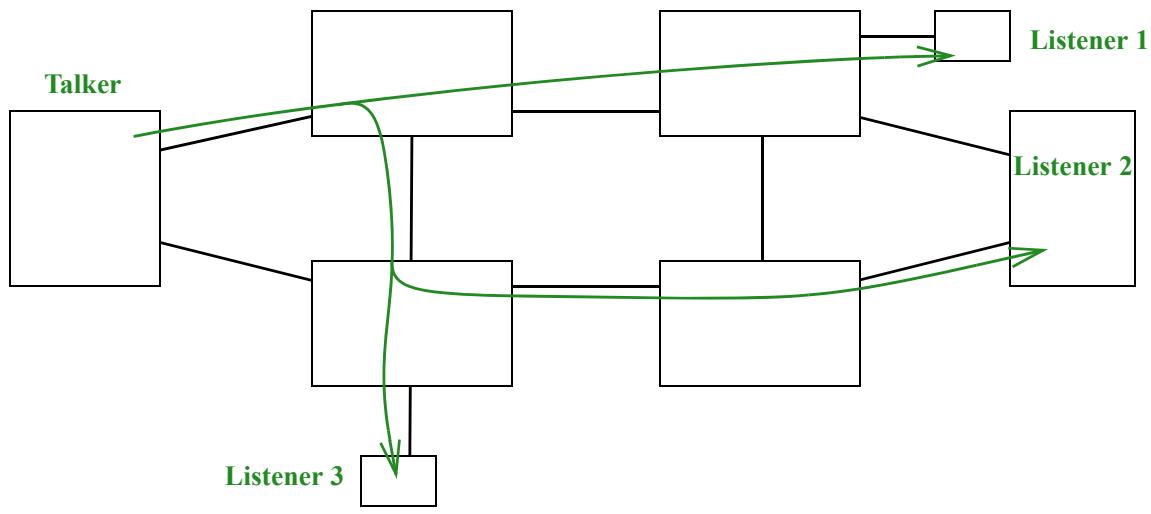
A Stream is the entity to which the Qualities of Service (QoSs) are offered. It is a sequence of packets, either unicast or multicast, from a Talker to one or more Listeners. Figure 6-2 illustrates a network carrying a single Stream.
Figure 6-2—A Stream with three Listeners
Stream identification is described in the following subclauses as follows:
a) Additional service subparameters required by Stream identification are in 6.1.
b) The Stream identification function is described in 6.2, and its placement in the protocol stack of a system in 6.3.
c) Four specific Stream identification functions are described: Null Stream identification (6.4), Source MAC and VLAN Stream identification (6.5), Active Destination MAC and VLAN Stream identification (6.6), and IP Stream identification (6.7).
These Stream identification functions are summarized in Table 6-1.
Table 6-1—Stream identification functions
<table><tr><td>Stream identification function</td><td>Active/passive</td><td>Examines</td><td>Overwrites</td><td>Reference</td></tr><tr><td>Null Stream identification</td><td>Passive</td><td>destination_address, vlan_identifier</td><td>None</td><td>6.4, 9.1.2</td></tr><tr><td>Source MAC and VLAN Stream identification</td><td>Passive</td><td>source_address, vlan_identifier</td><td>None</td><td>6.5, 9.1.3</td></tr><tr><td>Active Destination MAC and VLAN Stream identification</td><td>Active</td><td>destination_address, vlan_identifier</td><td>destination_address, vlan_identifier, priority</td><td>6.6, 9.1.4</td></tr><tr><td>IP Stream identification</td><td>Passive</td><td>destination_address, vlan_identifier, IP source address, IP destination address, DSCP, IP next protocol, source port, destination port</td><td>None</td><td>6.7, 9.1.5</td></tr></table>
6.1 Stream service subparameters
The ISS defined in IEEE Std 802.1AC includes a connection_identifier parameter that is of local significance (to a system) only. The parameter is not carried across the underlying service. Stream identification makes use of this parameter to carry parametrized information. Stream identification has need for more than one subparameter, but an implementor can create mathematical algorithms to combine those subparameters (and/or other subparameters for other layers) into a single connection_identifier parameter, especially since the connection_identifier’s values are undefined outside the system implementing them. In this document, parameters that are assumed to be encoded in the connection_identifier are deemed subparameters.
The parameters of the service offered by Stream identification include the following subparameters required by the Stream identification function and other functions defined in this standard:
a) stream_handle: An integer identifying the Stream to which the packet belongs.
b) sequence_number: An unsigned integer identifying the order in which the packet was transmitted relative to other packets in the same Compound Stream.
The numerical value of the stream_handle subparameter is local to a system; this subparameter is not to be confused with, for example, a field in a Protocol Data Unit (PDU) with a similar function. The value of a stream_handle is connected to protocol fields by means of protocol actions and network management. It can, but does not necessarily, have a 1:1 relationship with an explicit field in the packet.
Not every sequence of packets of interest to FRER (Clause 7) requires the relay systems along its path to identify to which Stream the packets belong. FRER does require the stream_handle and sequence_number subparameters in systems where a Sequence recovery function (7.4.2) or Individual recovery function (7.5) is configured for a Stream.
The numerical value of the sequence_number subparameter can be explicitly encoded in the packet by either the Stream identification function (6.2) or the Sequence encode/decode function (7.6).
6.2 Stream identification function
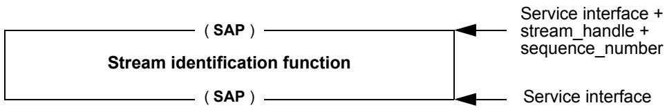
As illustrated in Figure 6-3, the Stream identification function can be described as having two SAPs (see IEEE Std 802.1AC). One SAP connects Stream identification function to the upper layers. This SAP includes a stream_handle subparameter and can include a sequence_number subparameter. The other SAP connects to the lower layers. This SAP can, but typically does not, include the stream_handle or sequence_number subparameters.
Figure 6-3—Stream identification function: single upper SAP
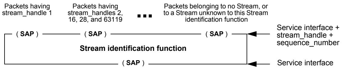
Equivalently, the Stream identification function can be described as having the same SAP to the lower layers, but as having an array of SAPs to the upper layers. A unique SAP corresponds to each value of the stream_handle subparameter, including one SAP for packets belonging to no known Stream. An SAP can serve more than one stream_handle value. This is illustrated in Figure 6-4.
Figure 6-4—Stream identification function: array of upper SAPs
The Stream identification function performs two functions:
a) Packets received from the lower layer are examined by the Stream identification function to determine a value for the stream_handle subparameter for that packet, i.e., to determine to which Stream the packet belongs.
1) If the packet belongs to a Stream known to this Stream identification function the resultant packet is passed, along with the stream_handle and any other subparameters (e.g., sequence_number) extracted from the packet, to the upper layers. Depending on the particular Stream identification method (or methods) employed, parameters can be modified (e.g., a tag can be removed or an address changed) by the Stream identification function.
2) Otherwise (the packet belongs to no known Stream), the packet is passed unchanged to the next upper layer with null values for the stream_handle and sequence_number subparameters.
b) For packets passed down from the upper layers for transmission, the Stream identification function uses the packet’s stream_handle subparameter to determine how to handle the packet:
1) If the packet belongs to a Stream known to this Stream identification function the resultant packet is passed to the lower layers. Depending on the particular Stream identification method (or methods) employed, parameters can be modified (e.g., a tag can be added or an address changed) by the Stream identification function.
2) Otherwise (the packet belongs to no known Stream), the packet is passed unchanged to the next lower layer with all parameters intact.
NOTE—The Stream identification method does not necessarily involve an actual transformation of the packet. See 6.4 and 6.6 for examples of both cases.
6.3 Stream identification in systems
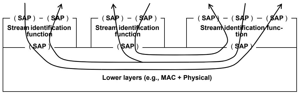
FRER (Clause 7) capabilities generally require Stream identification in order to function. How the Stream identification function (6.2) and the various FRER functions (7.4, 7.6) are arranged to accomplish a given task, and how they are described for the purposes of standards specification, can vary. Diagram a in Figure 6-5 illustrates a relay system (e.g., 8.6 of IEEE Std 802.1Q-2014) with two ports, that has its FRER capabilities embedded in its forwarding function, and not shown explicitly in the diagram. This formulation is the simplest, but does not make clear the ordering of operations, at least in the diagram.
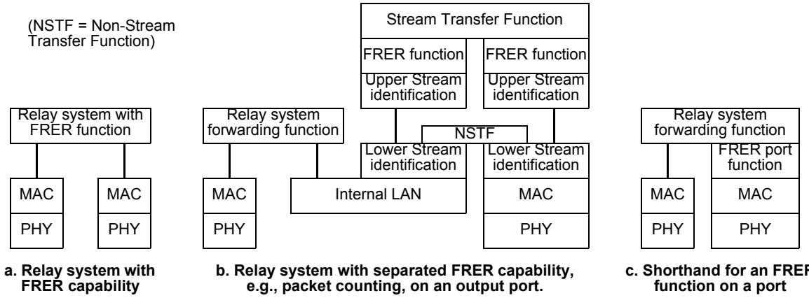
Figure 6-5—Stream functions in a relay system (three views of same system)
Diagram b in Figure 6-5 shows that same relay system, this time with the FRER functions placed explicitly in one of its ports, the picture of which is greatly expanded. In Diagram b, the forwarding function has no FRER capabilities. Stream identification functions extract Stream identification function subparameters in order to enable an FRER function. The Stream Transfer Function acts as a two-port packet relay, residing entirely inside the one port of the relay system, relaying packets belonging to Streams. The Non-Stream Transfer Function (NSTF) does the same, but attaches to the “unknown” SAP of Figure 6-4, and thus relays packets not recognized as belonging to Streams. The Lower Stream identification functions separate FRER packets from non-FRER packets; the latter are relayed across the NSTF as if the FRER capabilities were not present. The Upper Stream identification functions identify the FRER packets’ Streams so that the other FRER functions can perform their tasks. Each of the two-port transfer functions have a pair of SAPs, and transfer all packet receive indications into packet requests on the other SAP. This formulation illustrates exactly the peering relationships among the various functions, but is too complex for many purposes.
Diagram c in Figure 6-5 shows a way of illustrating the function in diagram b in a more compact manner. The operations to be performed can be more explicit than for diagram a, but the FRER sublayers are not at the right peering level).
It is sometimes necessary to differentiate between functions that are on one side or the other of the expanded port diagram (diagram b in Figure 6-5), Figure 6-6 illustrates a relay system with two ports, one of which has in- and out-facing FRER functions, and an end system with one port, with out-facing FRER functions. Every function communicates to its peers by sending and receiving packets through the real or virtual service layers below it. Thus, in-facing functions are on the side of the Stream Transfer Function towards the relay system’s forwarding function, and out-facing functions are on either the side of the Stream Transfer Function away from the forwarding function, or on a simple port, between the forwarding function and the underlying real or virtual service layer. Typically, in-facing FRER functions are used for proxy functions operating on behalf of end systems that are not FRER-capable. See Annex C for examples of the use of inand out-facing FRER functions. (The MAC and PHY layers are the Media Access Control and physical layers, respectively.)
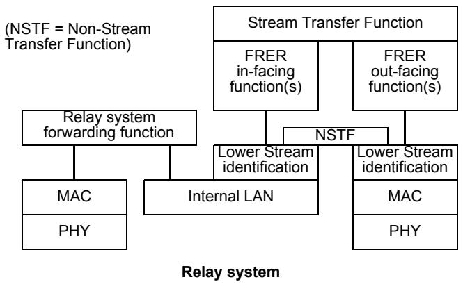
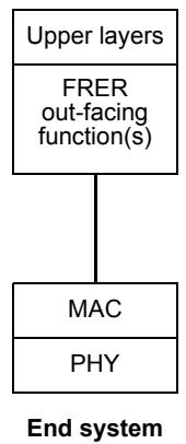
Figure 6-6—In- and out-facing functions
6.4 Null Stream identification
The Null Stream identification is a passive Stream identification function that operates at the frame level. It can be defined using the Enhanced Internal Sublayer Service (EISS) described in 6.9 of IEEE Std 802.1Q-2014, in which case it is enhanced with the extra stream_handle subparameter of the connection_identifier, specified in 6.1 of the present standard. It discards the stream_handle subparameter passed down the stack. It generates a stream_handle subparameter on frames passed up the stack based on the frame’s destination MAC address and VLAN ID. It does not change any of a packet’s other parameters. It is suitable for applications in which all data packets to a particular {MAC address, VLAN} pair are Stream packets. For example, AVB Streams (IEEE Std 802.1BA-2011 [B1]) have a unique {destination MAC address, VLAN} pair per Stream. In order to instantiate the Null Stream identification function, the tsnStreamIdIdentificationType managed object (9.1.1.6) is encoded using the OUI (00-80-C2) and the type values as shown in Table 9-1.
The managed objects for Null Stream identification are described in 9.1.2.
NOTE—The drop_eligible parameter is also present, along with the VLAN identifier and priority, in an IEEE 802.1Q VLAN tag. FRER does not affect the use of this parameter. It passes through Null Stream identification unchanged, and defaults to False when not present.
6.5 Source MAC and VLAN Stream identification
The Source MAC and VLAN Stream identification is a passive Stream identification function that operates at the frame level. It can be defined using the EISS described in 6.9 of IEEE Std 802.1Q-2014, in which case it is enhanced with the extra stream_handle subparameter of the connection_identifier, specified in 6.1 of the present standard. It discards the stream_handle subparameter passed down the stack. It generates a stream_handle subparameter on frames passed up the stack based on the frame’s source MAC address and VLAN ID. It does not change any of a packet’s parameters. It is suitable for applications in which all data packets from a particular {source MAC address, VLAN} pair are Stream packets. In order to instantiate the Source MAC and VLAN Stream identification function, the tsnStreamIdIdentificationType managed object (9.1.1.6) is encoded using the OUI (00-80-C2) and the type values as shown in Table 9-1.
The managed objects for Source MAC and VLAN Stream identification are described in 9.1.3.
NOTE—The drop_eligible parameter is also present, along with the VLAN identifier and priority, in an IEEE 802.1Q VLAN tag. FRER does not affect the use of this parameter. It passes through Source MAC and VLAN Stream identification unchanged, and defaults to False when not present.
6.6 Active Destination MAC and VLAN Stream identification
The Active Destination MAC and VLAN Stream identification is an active Stream identification function that operates at the frame level. It can be defined using the EISS described in 6.9 of IEEE Std 802.1Q-2014, in which case it is enhanced with the extra stream_handle subparameter of the connection_identifier, specified in 6.1 of the present standard. In order to instantiate the Active Destination MAC and VLAN Stream identification function, the tsnStreamIdIdentificationType managed object (9.1.1.6) is encoded using the OUI (00-80-C2) and the type values as shown in Table 9-1.
In the Active Destination MAC and VLAN Stream identification, the destination_address, vlan_identifier, and priority parameters of the frame passed down the stack from the upper layers or up the stack from the lower layers are replaced with alternate values. The replacement values for frames transmitted down the stack to the Active Destination MAC and VLAN Stream identification, and used to recognize frames passed up the stack to the Active Destination MAC and VLAN Stream identification function, are those listed in 9.1.2. The replacement values for frames passed up the stack (not including the priority parameter) are in 9.1.4.
Active Destination MAC and VLAN Stream identification is useful for translating a particular Stream, within a Talker, to use a particular {MAC address, VLAN} pair to identify the Stream to IEEE 802.1Q Bridges in the network, and within a Listener, to recover the original addressing information before passing the packet up the protocol stack. It is also useful in a relay system that is providing that restoration as a proxy service for a Listener.
The managed objects for Active Destination MAC and VLAN Stream identification are described in 9.1.4.
NOTE 1—The drop_eligible parameter is also present, along with the VLAN identifier and priority, in an IEEE 802.1Q VLAN tag. FRER does not affect the use of this parameter. It passes through Active Destination MAC and VLAN Stream identification unchanged, and defaults to False when not present.
NOTE 2—Changing the destination MAC address and/or VLAN must be done carefully, if the receiver is to recognize the packet. For example, if Active Destination MAC and VLAN Stream identification is used along with IP Stream identification (6.7), the user can configure Active Destination MAC and VLAN Stream identification at the receiving end to restore the original destination MAC address and VLAN before delivery up the protocol stack.
6.7 IP Stream identification
The IP Stream identification is a passive Stream identification function that operates at the transport layer and Internet Protocol (IP) interface layer. It can be defined using the union of the IP address primitives listed in 9.1.5 and parameters defined by the EISS described in 6.9 of IEEE Std 802.1Q-2014, in which case it is enhanced with the stream_handle subparameter of the connection_identifier, specified in 6.1 of the present standard. In IP Stream identification, the IP and higher layer address parameters and the EISS parameters are used to determine the stream_handle subparameter of packets passed up the stack, and discards the stream_handle subparameter for packets passed down the stack. It does not change any of a packet’s other parameters. In order to instantiate the IP Stream identification function, the tsnStreamIdIdentificationType managed object (9.1.1.6) is encoded using the OUI (00-80-C2) and the type values as shown in Table 9-1.
IP Stream identification can be coupled, for example, with Active Destination MAC and VLAN Stream identification (6.6) to assign a particular {MAC address, VLAN, priority} triple to packets belonging to a particular unicast IP Stream, as shown in Figure 8-1, Port A, where IP Stream identification would be in the box labeled “Passive Upper Stream identification functions (6.2).”
The managed objects for IP Stream identification are described in 9.1.5.
NOTE—The drop_eligible parameter is also present, along with the VLAN identifier and priority, in an IEEE 802.1Q VLAN tag. FRER does not affect the use of this parameter. It passes through IP Stream identification unchanged, and defaults to False when not present.
7 Frame Replication and Elimination for Reliability
7.1 Overview of Frame Replication and Elimination for Reliability
7.1.1 Goals and objectives
FRER, as specified in this clause, provides increased reliability (reduced packet loss rates) for a Stream by sequence numbering and replicating every packet, in the source end system and/or in relay systems in the network, and eliminating those replicates in the destination end system and/or in other relay systems.
Figure 7-1 illustrates an example of a Compound Stream with four component Member Streams. In this example, a sequence_number subparameter (6.1) is generated and encoded into each packet in the leftmost box. Sequence recovery functions (7.4.2) eliminate duplicate packets, and the non-duplicate packets copied as a new Member Stream (with sequence numbers unchanged), at two intermediate points. The final two Member Streams are brought together and the duplicates eliminated at the destination at right. This configuration protects against all 7 possible one-link failures, and against 16 of 21 possible two-link failures.
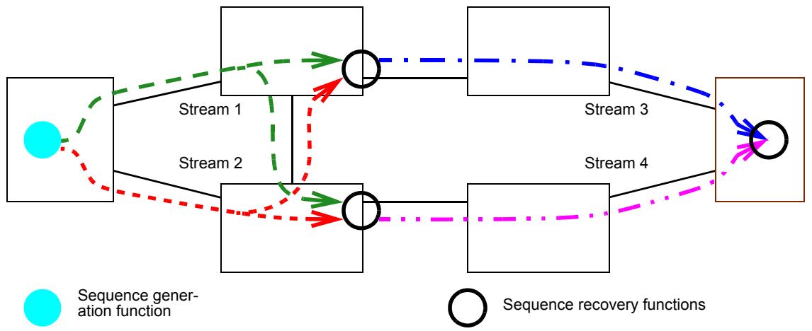
Figure 7-1—Compound Stream built from four Member Streams
FRER has the following goals and objectives:
a) Packet replication: By replicating packets, sending them on separate paths, and then using the sequence_number to eliminate replicates, the effective probability of packet loss is reduced.
NOTE 1—The means by which the multiple paths are created is the subject of other standards, including IEEE Std 802.1Q™, IEEE Std 802.1Qca™, and IEEE P802.1Qcc™. 10
b) Multicast or unicast: A path on which a Stream is sent can be a point-to-point path or a point-tomultipoint tree.
c) Intermittent Streams: A Stream such that there can be no more than one packet in flight on any given path than on any other path.
d) Bulk Streams: A Stream such that there can be many more packets in flight on any given path than on any other path.
NOTE 2—An equivalent distinction between bulk and intermittent Streams is that, at the point at which the Streams are combined, the difference between the sequence numbers of an intermittent Stream along the two paths can be no greater than 1. Bulk Streams, for which the difference can be greater than 1, require a somewhat more complex replicate deletion capability than intermittent Streams.
e) Flexible positioning: The FRER functions have to be usable in a number of configurations, as explained in Annex C, including (but not limited to):
1) In an end system’s protocol stack.
2) In a relay system’s protocol stack (e.g., systems C and F in Figure C-4).
3) In a relay system’s protocol stack, where the FRER functions are acting in proxy for an adjacent end system that lacks a FRER capability (e.g., system B in Figure C-4).
f) Latent error detection: When replicating a Stream, if a component along one path fails, it is not immediately apparent to the receiver that something is wrong, since the other path continues to deliver data. Given the higher reliability achievable with FRER, some means of detecting a failure to actually deliver copies of each packet is required at the point that the replicated packets are discarded.
g) Interoperability: There exist protocols antecedent to this standard that provide a similar function, but have details that are different from this standard that would make it difficult or impossible to design an interworking function that translates between the different standards’ packet formats. This standard defines a small number of controls that make such interoperation possible (see Annex B).
h) Backward compatibility: To increase the number of uses available for FRER, it is desirable for a set of end systems conforming to this standard to obtain most or all of the benefits of FRER when connected to a network that is not aware of FRER, and for a network of conformant relay systems to offer these benefits to unaware end systems.
i) Dynamic capability: Some applications will need to turn FRER on or off on an operational Stream, rather than only when the Stream is quiescent.
j) Robustness: At packet loss rates targeted by FRER, certain classes of errors, e.g., a stuck transmitter repeatedly sending the same packet, become more important than, for example, simple packet loss events. FRER has to be proof against such errors.
k) Zero congestion loss: Various techniques (e.g., IEEE 802.1BA-2011 [B1], Audio Video Bridging) can be used to provide a Stream with zero (or very low) packet loss due to congestion. FRER has to be compatible with such techniques.
NOTE 3—There are additional QoS features provided by Time-Sensitive Networking (TSN). FRER offers the most benefit when used in combination with other features, including especially zero congestion loss.
l) Ease of use: It must be possible to employ FRER without per-Stream configuration in each relay system.
In addition to the above goals, there are other possible capabilities that are explicitly not goals of this standard:
m) In-order delivery: FRER can cause packets belonging to a Compound Stream to be delivered in a sequence other than that in which they were transmitted. Rectifying this is beyond the scope of this standard.
If the paths of the Member Streams comprising a Compound Stream have significantly different lengths, and if the Streams are bulk Streams (item d), then a lost packet on the shorter path can easily give rise to an outof-order delivery when its duplicate arrives via the longer path, even though in-order delivery is maintained for each Member Stream along its own path. Delivering packets in their original order for the Compound Stream, as indicated by the sequence numbers, would require buffering the packets. Because of this buffering requirement, in-order delivery for a Compound Stream is explicitly not a goal of FRER. Users of Bridged Virtual LANs, as defined in IEEE Std 802.1Q, need to understand that the usual expectations of in-order delivery can be compromised by FRER.
FRER can be configured to apply recursively, so that a Compound Stream composed of Member Streams can itself be a Member Stream to an enclosing Compound Stream.
7.2 Use of the term Stream
Readers of this standard who are familiar with IEEE Std 802.1Q will recognize that the distinction between a Member Stream and a Compound Stream is required by the present standard. For example, in IEEE Std 802.1Q, the Stream is both the entire Talker-to-Listener path and that for which a bandwidth reservation must be made before the Stream can obtain the desired QoS. It is expected that bandwidth reservations using the mechanisms of IEEE Std 802.1Q could be made for each of the four Member Streams illustrated in Figure 7-1, while the end-to-end Talker-to-Listener path is the whole Compound Stream. (See C.9.)
In addition, IEEE Std 802.1Q defines a StreamID that is used to identify a stream between a Talker and one or more Listener(s). In contrast, the present standard defines a stream_handle subparameter that is used internally to identify a Stream.
Some end systems sequence number their packets per system, rather than per-Stream. Such an end system can transmit any number of separate Streams (in the sense of data flows), each with different destination_mac_address, IP address, TCP port numbers, VLANs, etc., each with its own entries in a relay system’s forwarding database and/or each with its own bandwidth reservation. In receiving end systems or in relay systems, Source MAC and VLAN Stream identification (6.5) is useful for organizing Individual recovery functions and Sequence recovery functions, because the sequence_number parameter is per-source MAC address, not per-destination MAC address; each state machine can operate on all of the individual Streams transmitted by a single source as a single Stream. Therefore, any number of individual Streams (in the bandwidth reservation sense) can be considered a single Stream (in the source MAC address sense) by different systems in a network. See also B.2.
7.3 Frame Replication and Elimination for Reliability functions
FRER provides five of the functions illustrated in Figure 7-2. Not all functions are required in every protocol stack.
<table><tr><td>Upper layer</td></tr><tr><td>Sequencing function (7.4)</td></tr><tr><td>Stream splitting function (7.7)</td></tr><tr><td>Individual recovery function (7.5)</td></tr><tr><td>Sequence encode/decode function (7.6)</td></tr><tr><td>Stream identification (Clause 6)</td></tr><tr><td>Lower layer</td></tr></table>
Figure 7-2—Frame Replication and Elimination for Reliability functions
a) Sequencing: This function (see 7.4):
1) Supplies a sequential value for the sequence_number subparameter for packets passed down from the upper layer for transmission (7.4.1);
2) Examines the sequence numbers of received packets passed up to it (from multiple Streams), and discards packets whose sequence_number subparameter indicates that it is a duplicate of a packet received previously (7.4.2); and
3) Monitors counter variables to detect latent errors of Streams passed up to it (7.4.4).
b) Stream splitting: This function (see 7.7):
1) Replicates each packet passed down to it, assigning each replicate a different stream_handle, at most one of which can be the same as the original.
2) Passes packets unchanged up the stack.
c) Individual recovery: This function (see 7.5):
1) Examines the sequence numbers of received packets passed up to it (belonging to Member Streams), and discards packets whose sequence_number subparameter indicates that it is a duplicate of a packet received previously.
d) Sequence Encode/Decode: This function (see 7.6):
1) Encodes the sequence_number subparameter into the packet in a manner such that it can be decoded by its peer Sequencing function(s) by altering the other packet parameters, typically by encoding the sequence_number in the packet data by some means, e.g., an R-TAG (7.8).
2) Extracts the sequence_number from a received packet passed up to it. Depending on the Stream identification function used, the Sequencing function can remove the sequence_number encapsulation from the packet.
The Sequence encode/decode function is not required if the Stream identification function used in the stack encodes all of the required subparameters.
FRER also requires the Stream identification function (Clause 6):
e) Stream identification: This function (see Clause 6):
1) Passes each packet down the stack and, if required by the particular encapsulation method configured, uses the stream_handle to alter the packet; and
2) Derives a stream_handle from a received packet and passes it up the stack, altering the packet if required by the encapsulation method.
7.4 Sequencing function
The Sequencing function makes use of the stream_handle and sequence_number service subparameters of 6.1. The Sequencing function has two kinds of component functions. Sequence generation functions (7.4.1) operate on packets passed down the protocol stack towards the physical layer in Figure 7-2 and generate a value for the sequence_number subparameter. Sequence recovery functions (7.4.2) operate on packets passed up the stack towards the higher layer functions and use the sequence_number subparameter to decide which packets to pass and which to discard.
On any given port, zero or more instances of the Sequence generation function, and/or Sequence recovery function can be instantiated. These functions can be instantiated as in-facing or out-facing functions. For both kinds of functions, the stream_handle subparameter of a packet determines through which function, if any, the packet is passed. Each instance of each function has its own set of state variables.
7.4.1 Sequence generation function
The sequence generation function resides in the Sequencing function (7.4). It generates a sequence_number subparameter for each packet of a Stream passed down to the lower layers. There is at most one sequence generation function per port per stream_handle value per direction (in-facing or out-facing), as specified through managed objects (10.3).
The sequence generation function is described in terms of the following:
a) Managed objects that control the sequence generation function and that are affected by the sequence generation function (10.3, 10.8);
b) Events, the occurrence of which trigger the execution of code routines, and that can be triggered by the code routines (7.4.1.1);
c) Variables that are manipulated by the code routines and maintain the state of the sequence generation function between routine executions (7.4.1.2); and
d) Two code routines that interact with the managed objects, events, and variables (7.4.1.4, 7.4.1.3).
7.4.1.1 Events for sequence generation
There are two events that can affect the sequence generation function, and one that it produces.
a) BEGIN: The global event that resets all functions, including the sequence generation function. This event triggers the execution of the SequenceGenerationReset routine (7.4.1.3).
b) DATA_REQUEST: The event that presents a packet from the upper layers to the sequence generation function for transmission to the lower layers, e.g., the M_UNITDATA.request primitive of the ISS of IEEE Std 802.1AC. This event triggers the execution of the SequenceGenerationAlgorithm routine (7.4.1.4).
c) SEND_DATA: The event that presents a packet down the stack from the sequence generation function to the lower layers, e.g., the M_UNITDATA.request primitive of the ISS of IEEE Std 802.1AC.
7.4.1.2 Variables for sequence generation
Each instance of the sequence generation function has its own set of variables, independent from any other instance.
7.4.1.2.1 GenSeqSpace
GenSeqSpace specifies the range of values for the sequence_number subparameter and other variables that depend on it. It is a constant with the value 65 536.
7.4.1.2.2 GenSeqNum
The GenSeqNum variable contains the value that the sequence generation function increments after passing down to the lower layer as the sequence_number subparameter. The variable is an unsigned integer in the range 0 to (GenSeqSpace – 1). GenSeqSpace is defined in 7.4.1.2.1. GenSeqNum is initialized to 0 whenever the function is reset (7.4.1.3), and incremented by 1 after its value is copied to the sequence_number subparameter. When incremented past its maximum value, the new value is 0.
7.4.1.3 SequenceGenerationReset
The SequenceGenerationReset function is called whenever the BEGIN event occurs (item a in 7.4.1.1) or the value True is written to the frerSeqRcvyReset managed object (10.4.1.4). It resets GenSeqNum (7.4.1.2.2) and increments frerCpsSeqGenResets (10.8.2).
  void SequenceGenerationReset () {
  GenSeqNum = 0;
  frerCpsSeqGenResets = frerCpsSeqGenResets + 1;
  }
7.4.1.4 SequenceGenerationAlgorithm
The SequenceGenerationAlgorithm function is called whenever the DATA_REQUEST (item b in 7.4.1.1) event occurs. It copies GenSeqNum (7.4.1.2.2) to the sequence_number subparameter (item b in 6.1) and increments GenSeqNum. It then triggers the SEND_DATA primitive (item c in 7.4.1.1) to pass the packet on to the next lower layer.
  void SequenceGenerationAlgorithm () {
  unsigned int sequence_number = GenSeqNum;
  if (GenSeqNum >= (GenSeqSpace - 1))
  GenSeqNum = 0;
  else
  GenSeqNum = GenSeqNum + 1;
  SEND_DATA; // Pass packet & sequence_number subparameter down stack
  }
7.4.2 Sequence recovery function
The Sequence recovery function operates on a merged set of Member Streams originally marked with sequence_number (6.1) values from a single instance of the Sequence generation function (7.4.1). It is not to be confused with the Individual recovery function (7.5) that applies to only one Member Stream, although both use the same basic algorithms.
An instantiation of the Sequence recovery function consists of the following:
a) An instantiation of the Base recovery function (7.4.3), either the VectorRecoveryAlgorithm (7.4.3.4) or the MatchRecoveryAlgorithm (7.4.3.5), with its frerSeqRcvyIndividualRecovery object (10.4.1.10) set to False, configured to apply to one or more values of the sequence_number subparameter; and
b) An instantiation of the Latent error detection function (7.4.4).
Managed objects (Clause 9 and Clause 10) are used to instantiate these functions on ports of a system.
NOTE—The managed objects in Clause 9 and Clause 10 create an instantiation of the Sequence recovery function per port. In fact, a relay system can choose to create a single instance of the Sequence recovery function as part of its forwarding function, or one instance per line card, or in some other, distributed fashion, without violating the externally visible behaviors specified by this standard. The per-instantiation variables are internal to the system, so their definitions are not affected by this choice. See 10.8.1 for a discussion of what this choice means for the counters in Clause 9 and Clause 10 that are referenced by instantiations of the Sequence recovery function.
7.4.3 Base recovery function
A Base recovery function resides in the Sequencing function (7.4). It evaluates the sequence_number subparameter of a packet of one or more Member Streams passed up from the lower layers, in order to discard duplicated packets. A given instantiation of a Base recovery function can function as either a Sequence recovery function (7.4.2) or an Individual recovery function (7.5). This choice, the selection of stream_handle subparameter value(s) to which an instantiation applies, the port and direction (in-facing or out-facing) on which it resides, and other operational parameters are specified through managed objects (10.4).
The sequence recovery function is described in terms of the following:
a) Managed objects that control the sequence recovery function and that are affected by the sequence recovery function (10.4, 10.8);
b) Events, the occurrence of which trigger the execution of code routines and which can be triggered by the code routines (7.4.3.1);
c) Variables that are manipulated by the code routines and maintain the state of the sequence recovery function between routine executions (7.4.3.2); and
d) Four code routines that interact with the managed objects, events, and variables (7.4.3.3, 7.4.3.4, 7.4.3.5, 7.4.3.6).
The sequence recovery function has two sequence recovery algorithms (7.4.3.4, 7.4.3.5) so that it can be used either for Intermittent Streams (item c in 7.1.1) or for Bulk Streams (item d in 7.1.1). As long as the maximum difference in the number of packets in flight among all of the paths taken by the Member Streams served by a given sequence recovery function does not exceed the size of the SequenceHistory variable (7.4.3.2.2, 10.4.1.6), the packets are delivered without duplication, but can be delivered out-of-order. If the difference exceeds this value, then duplicate packets can be delivered.
NOTE 1—The requirements for conformance to this standard, particularly item c in 5.9 and item e in 5.12, specify that the sequence recovery function need only support a minimum difference in path length for the correct elimination of duplicates in Bulk Streams. If the actual path difference in a given network exceeds the capability of a sequence recovery function, then duplicate packets will be delivered. It is up to the user to see that the capabilities of the systems purchased match the needs of the particular network in which they are employed.
A FRER recovery function shall not process a packet unless the lower-level packet validity checks (e.g., IEEE Std 802.3 [B2], Frame Check Sequence) have been completed successfully.
NOTE 2—This restriction has the effect of disallowing cut through forwarding on a port on which the FRER recovery function is discarding packets.
7.4.3.1 Events for sequence recovery
There are three events that can affect the sequence recovery function, and one that the Base recovery function can trigger.
a) BEGIN: The global event that resets all functions, including the sequence recovery function. This event triggers the execution of the SequenceRecoveryReset routine (7.4.3.3).
b) DATA_INDICATION: The event that presents a packet up the stack to the sequence recovery function from the lower layers, e.g., the M_UNITDATA.indication primitive of the ISS of IEEE Std 802.1AC.
c) RECOVERY_TIMEOUT: The event that occurs when the RemainingTicks (7.4.3.2.4) variable reaches 0. It triggers the execution of the SequenceRecoveryReset routine (7.4.3.3).
d) PRESENT_DATA: The event that presents a packet up the stack from the sequence recovery function to the upper layers, e.g., the M_UNITDATA.indication primitive of the ISS of IEEE Std 802.1AC. This event can be triggered by the VectorRecoveryAlgorithm routine (7.4.3.4) and the MatchRecoveryAlgorithm routine (7.4.3.5).
7.4.3.2 Variables for sequence recovery
Each instance of the sequence recovery function has its own set of variables, independent from any other instance.
7.4.3.2.1 RecovSeqSpace
RecovSeqSpace specifies the range of values for the sequence_number subparameter and other variables that depend on it. It is a constant with the value 65 536.
7.4.3.2.2 SequenceHistory
The SequenceHistory variable maintains a history of the sequence_number subparameters of recently received packets. The SequenceHistory variable is a bit vector, with one bit for each value from 0 to (frerSeqRcvyHistoryLength – 1), corresponding to sequence_numbers in the range RecovSeqNum (7.4.3.2.3) through (RecovSeqNum – frerSeqRcvyHistoryLength + 1), inclusive, with the arithmetic in both expressions performed modulo frerSeqRcvyHistoryLength. A 1 in the SequenceHistory indicates that the corresponding sequence_number has been received, and a 0 that it has not.
7.4.3.2.3 RecovSeqNum
The RecovSeqNum variable holds the highest sequence_number value received (modulo RecovSeqSpace), or the value (RecovSeqSpace – 1), if none have been received since the sequence recovery function was reset. The variable is an unsigned integer in the range 0 to (RecovSeqSpace – 1). RecovSeqSpace is defined in 7.4.3.2.1. RecovSeqNum is initialized to (RecovSeqSpace – 1) whenever the function is reset (7.4.3.3). When incremented past its maximum value, the new value is 0.
7.4.3.2.4 RemainingTicks
An unsigned integer variable that holds the number of clock ticks remaining until a RECOVERY_TIMEOUT event (item c in 7.4.3.1) occurs. It is decremented regularly, at the rate indicated by TicksPerSecond (7.4.3.2.5), and can be reset by the VectorRecoveryAlgorithm (7.4.3.4) and the MatchRecoveryAlgorithm (7.4.3.5). When RemainingTicks decrements from 1 to 0, a RECOVERY_TIMEOUT event occurs, and RemainingTicks remains at 0.
7.4.3.2.5 TicksPerSecond
An unsigned integer value, supplied by the implementation, that indicates the number of times per second that the variable RemainingTicks (7.4.3.2.4) is decremented. The value of TicksPerSecond shall be 100 or greater.
7.4.3.2.6 TakeAny
A Boolean value indicating whether the recovery algorithm (7.4.3.4 or 7.4.3.5) is to accept the next packet, no matter what the value of its sequence_number subparameter.
7.4.3.3 SequenceRecoveryReset
SequenceRecoveryReset is called whenever the BEGIN event (item a in 7.4.3.1) or the RECOVERY_TIMEOUT event (item c in 7.4.3.1) occurs. It resets the RecovSeqNum (7.4.3.2.3) and SequenceHistory (7.4.3.2.2) variables to their initial states, increments frerCpsSeqRcvyResets (10.8.9), and sets TakeAny (7.4.3.2.6). Note that RecovSeqNum and SequenceHistory are reset only if the VectorRecoveryAlgorithm (7.4.3.4) is configured.
  void SequenceRecoveryReset (
  if (frerSeqRcvyAlgorithm == Vector_Alg) {
  int i;
  RecovSeqNum = RecovSeqSpace - 1;
  for (i = 0; i < frerSeqRcvyHistoryLength; i = i + 1)
  SequenceHistory[i] = 0; // Set all bits 0 (packet not seen)
  }
  frerCpsSeqRcvyResets = frerCpsSeqRcvyResets + 1;
  TakeAny = true;
  }
7.4.3.4 VectorRecoveryAlgorithm
VectorRecoveryAlgorithm is called whenever the DATA_INDICATION event occurs (item b in 7.4.3.1) and the Sequence recovery function is configured to use the VectorRecoveryAlgorithm (frerSeqRcvyAlgorithm = Vector_Alg, 10.4.1.5). If it terminates without triggering the PRESENT_DATA event (item d in 7.4.3.1), then the packet is effectively discarded. Each instance of the function is controlled by the constant RecovSeqSpace (7.4.3.2.1) and the managed object frerSeqRcvyHistoryLength (10.4.1.6).
One can observe that if the managed object frerSeqRcvyHistoryLength contains the value 1, then this algorithm is suitable for Intermittent Streams (item c in 7.1.1). In that case, the SequenceHistory variable (7.4.3.2.2) merely records whether the RecovSeqNum (7.4.3.2.3) does or does not record the sequence_number subparameter of a received packet. [It does not immediately after SequenceRecoveryReset (7.4.3.3) is called.] If frerSeqRcvyHistoryLength contains a value greater than one, VectorRecoveryAlgorithm serves as the more complex algorithm suitable for Bulk Streams (item d in 7.1.1).
Immediately after SequenceRecoveryReset (7.4.3.3) is called, the VectorRecoveryAlgorithm accepts the first packet received as valid. After the first packet has been accepted, all subsequent packets that are in the window last packet number accepted ± frerSeqRcvyHistoryLength are accepted, and those packets with sequence_number values outside that range are discarded. Each packet accepted and passed up the stack resets the timer variable RemainingTicks (7.4.3.2.4). If that variable ticks down to 0, meaning that no packet has been accepted in frerSeqRcvyResetMSec milliseconds (10.4.1.7), then SequenceRecoveryReset again resets the algorithm, and the next packet received is accepted.
This timeout mechanism means that:
a) “Rogue” packets, meaning packets outside the frerSeqRcvyHistoryLength window, are discarded as invalid.
b) If a Base recovery function somehow gets out of step with its corresponding Sequence generation function, then after frerSeqRcvyResetMSec milliseconds, the Base recovery function will be reset and data will again be passed.
c) If a Sequence generation function is reset, perhaps by rebooting a system, then Base recovery functions that have not been reset are likely to discard packets until the timeout has occurred.
d) If a Talker or a relay system fails in such a way as to repeatedly transmit packets with the same sequence_number subparameter (perhaps repeating exactly the same packet), those packets will continue to be discarded, at least until the sequence_number wraps around.
NOTE—Individual recovery functions (7.5) can be configured to discard repeated sequence_number values (or sequences of values) and prevent even this wrap around problem.
As a result of item d, it is advisable for a Listener or relay system to be configured to discard packets in a single Member Stream. See 7.5 and C.10.
  void VectorRecoveryAlgorithm () {
  // Check that sequence number is present in the packet
  unsigned int sequence_number;
  if (sequence_number == frerSeqRcvyInvalidSequenceValue) {
  frerCpsSeqRcvyTaglessPackets = frerCpsSeqRcvyTaglessPackets + 1;
  if (frerSeqRcvyTakeNoSequence) {
  frerCpsSeqRcvyPassedPackets = frerCpsSeqRcvyPassedPackets + 1;
  frerCpSeqRcvyPassedPackets = frerCpSeqRcvyPassedPackets + 1;
  RemainingTicks = ((frerSeqRcvyResetMSec*TicksPerSecond) + 999) / 1000;
  PRESENT_DATA;
  } else {
  frerCpsSeqRcvyDiscardedPackets =
  frerCpsSeqRcvyDiscardedPackets + 1;
  frerCpSeqRcvyDiscardPackets = frerCpSeqRcvyDiscardPackets + 1;
  }
  return;
  // Compute signed difference modulo RecovSeqSpace.
  int delta = (sequence_number-RecovSeqNum) & (RecovSeqSpace - 1);
  if (0 != (delta & (RecovSeqSpace/2)))
  delta = delta - RecovSeqSpace;
  // Here, -(RecovSeqSpace/2)<=delta<=(RecovSeqSpace/2)-1)
  // After reset, accept any packet
  if (TakeAny) {
  TakeAny    = false;
  SequenceHistory[0]    = 1;    // Shift, adding a "seen" bit
  RecovSeqNum    = sequence_number;
  frerCpsSeqRcvyPassedPackets = frerCpsSeqRcvyPassedPackets + 1;
  frerCpSeqRcvyPassedPackets = frerCpSeqRcvyPassedPackets + 1;
  RemainingTicks    =
  ((frerSeqRcvyResetMSec * TicksPerSecond) + 999) / 1000;
  PRESENT_DATA;
  } else if (delta >= frerSeqRcvyHistoryLength ||
  delta <= -frerSeqRcvyHistoryLength )
  {
  // Packet is out-of-range. Count and discard it.
  frerCpsSeqRcvyRoguePackets = frerCpsSeqRcvyRoguePackets + 1;
  frerCpSeqRcvyDiscardPackets = frerCpSeqRcvyDiscardPackets + 1;
  // Reset timer if working on an individual Stream
  if (frerSeqRcvyIndividualRecovery)
  RemainingTicks    =
  ((frerSeqRcvyResetMSec * TicksPerSecond) + 999) / 1000;
  } else if (delta <= 0) {
  // Packet is old and in SequenceHistory; have we seen it before?
  if (0 == SequenceHistory[-delta]) {
  // Packet has not been seen. Take it.
  SequenceHistory[-delta]    = 1;
  frerCpsSeqRcvyOutOfOrderPackets =
  frerCpsSeqRcvyOutOfOrderPackets + 1;
  frerCpsSeqRcvyPassedPackets = frerCpsSeqRcvyPassedPackets + 1;
  frerCpSeqRcvyPassedPackets = frerCpSeqRcvyPassedPackets + 1;
  RemainingTicks    =
  ((frerSeqRcvyResetMSec * TicksPerSecond) + 999) / 1000;
  PRESENT_DATA;
  } else {
  // Packet has been seen. Do not forward. Count the discard.
  frerCpsSeqRcvyDiscardedPackets =
  frerCpsSeqRcvyDiscardedPackets + 1;
  frerCpSeqRcvyDiscardPackets = frerCpSeqRcvyDiscardPackets + 1;
  // Reset timer if working on an individual Stream
  if (frerSeqRcvyIndividualRecovery)
  RemainingTicks    =
  ((frerSeqRcvyResetMSec * TicksPerSecond) + 999) / 1000;
  }
  } else {
  // Packet is not too far ahead of the one we want.
  // Packet is out-of-order unless it directly follows RecovSeqNum
  if (delta != 1)
  frerCpsSeqRcvyOutOfOrderPackets =
  frerCpsSeqRcvyOutOfOrderPackets + 1;
  // Shift the history until bit 0 refers to sequence_number.
  while (0 != (delta = delta - 1))
  ShiftSequenceHistory(0); // Shift, adding a "not seen" bit
  ShiftSequenceHistory(1); // Shift, adding a "seen" bit
  RecovSeqNum = sequence_number;
  frerCpsSeqRcvyPassedPackets = frerCpsSeqRcvyPassedPackets + 1;
  frerCpSeqRcvyPassedPackets = frerCpSeqRcvyPassedPackets + 1;
  RemainingTicks =
  ((frerSeqRcvyResetMSec * TicksPerSecond) + 999) / 1000;
  PRESENT_DATA;
  }
7.4.3.5 MatchRecoveryAlgorithm
MatchRecoveryAlgorithm is called whenever the DATA_INDICATION event occurs (item b in 7.4.3.1) and the Sequence recovery function is configured to use the MatchRecoveryAlgorithm (frerSeqRcvyAlgorithm = Match_Alg, 10.4.1.5). If it terminates without triggering the PRESENT_DATA event (item d in 7.4.3.1), then the packet is effectively discarded.
Immediately after SequenceRecoveryReset (7.4.3.3) is called, the MatchRecoveryAlgorithm accepts the first packet received as valid. After the first packet has been accepted, all subsequent packets either match the last packet number accepted, and are therefore discarded, or do not, in which case they are accepted. Each packet accepted and passed up the stack resets the timer variable RemainingTicks (7.4.3.2.4). If that variable ticks down to 0, meaning that no packet has been accepted in frerSeqRcvyResetMSec milliseconds (10.4.1.7), then SequenceRecoveryReset again resets the algorithm, and the next packet received is accepted.
The timer mechanism prevents the MatchRecoveryAlgorithm from getting stuck forever, blocking packet 1, in case a Talker fails or is reset soon after initialization.
If a Talker or a relay system fails in such a way as to repeatedly transmit packets with the same sequence_number subparameter (perhaps repeating exactly the same packet), those packets will continue to be discarded, at least until the sequence_number wraps around. At that point, either the stuck packet or the right packet could be passed. Therefore, it is advisable for a Listener or relay system to be configured to discard packets in a single Member Stream. See 7.5 and C.10.
NOTE—Individual recovery functions (7.5) can be configured to discard repeated sequence_number values (or sequences of values) and prevent even this wrap around problem.
  void MatchRecoveryAlgorithm () {
  // Check that sequence number is present in the packet
  unsigned int sequence_number;
  if (sequence_number; == frerSeqRcvyInvalidSequenceValue) {
  frerCpsSeqRcvyTaglessPackets = frerCpsSeqRcvyTaglessPackets + 1;
  frerCpsSeqRcvyPassedPackets = frerCpsSeqRcvyPassedPackets + 1;
  frerCpSeqRcvyPassedPackets = frerCpSeqRcvyPassedPackets + 1;
  PRESENT_DATA;
  return;
  }
  // After reset, accept any packet
  if (TakeAny) {
  TakeAny = false;
  RecovSeqNum = sequence_number;
  frerCpsSeqRcvyPassedPackets = frerCpsSeqRcvyPassedPackets + 1;
  frerCpSeqRcvyPassedPackets = frerCpSeqRcvyPassedPackets + 1;
  RemainingTicks =
  ((frerSeqRcvyResetMSec * TicksPerSecond) + 999) / 1000;
  PRESENT_DATA;
  }
  // Compute signed difference modulo RecovSeqSpace.
  int delta = (sequence_number-RecovSeqNum) & (RecovSeqSpace - 1);
  if (delta == 0) {
  // Packet has been seen. Do not forward. Count the discard.
  frerCpsSeqRcvyDiscardedPackets = frerCpsSeqRcvyDiscardedPackets + 1;
  frerCpSeqRcvyDiscardPackets = frerCpSeqRcvyDiscardPackets + 1;
  // Reset timer if working on an individual Stream
  if (frerSeqRcvyIndividualRecovery)
  RemainingTicks =
  ((frerSeqRcvyResetMSec * TicksPerSecond) + 999) / 1000;
  } else {
  // Packet has not been seen; accept it.
  // Packet is out-of-order unless it directly follows RecovSeqNum
  if (delta != 1)
  frerCpsSeqRcvyOutOfOrderPackets = frerCpsSeqRcvyOutOfOrderPackets + 1;
  RecovSeqNum = sequence_number;
  frerCpsSeqRcvyPassedPackets = frerCpsSeqRcvyPassedPackets + 1;
  frerCpSeqRcvyPassedPackets = frerCpSeqRcvyPassedPackets + 1;
  RemainingTicks =
  ((frerSeqRcvyResetMSec * TicksPerSecond) + 999) / 1000;

  PRESENT_DATA;
  }
7.4.3.6 ShiftSequenceHistory
This routine is called by the VectorRecoveryAlgorithm routine (7.4.3.4) to advance the SequenceHistory bit array (7.4.3.2.2) and to count lost packets (frerCpsSeqRcvyLostPackets, 10.8.7). ShiftSequenceHistory takes one parameter, which is the new value for index 0 in the SequenceHistory bit array.
  void ShiftSequenceHistory (int newZeroValue) {
  int i;
  if (0 == SequenceHistory[frerSeqRcvyHistoryLength - 1])
  frerCpsSeqRcvyLostPackets = frerCpsSeqRcvyLostPackets + 1;
  for (i = frerSeqRcvyHistoryLength - 1; i != 0; i = i - 1)
  SequenceHistory[i] = SequenceHistory[i - 1];
  SequenceHistory[0] = newZeroValue;
  }
7.4.4 Latent error detection function
Each instance of a Latent error detection function is part of a Sequence recovery function (7.4.2). It monitors the managed objects associated with a single instance of the Base recovery function (7.4.3), in order to detect the condition that relatively few packets are being discarded by that function. Latent error detection operates on the assumption that, in a properly functioning Compound Stream employing n paths into the current system, there will be n – 1 packets discarded for every packet passed through the Base recovery function (7.4.3). The latent error detection function issues a SIGNAL_LATENT_ERROR (item d in 7.4.4.1) when that assumption is violated.
There is at most one latent error detection function per port per stream_handle value per direction (in-facing or out-facing), as specified through the managed objects (10.4) that control both functions. For every Base recovery function configured, there can be only zero or one associated latent error detection function. Any implementation that supports the Base recovery function shall support the Latent error detection function.
Latent error detection is accomplished by two periodic functions. The first (LatentErrorTest, 7.4.4.4) examines the number of packets passed and discarded, and reports a latent error if the differences among those counters exceed a set threshold. The other periodic function (LatentErrorReset, 7.4.4.3) resets the variables used by the first, so that occasional random packet losses do not accumulate forever. These functions are driven by timers, not by the receipt or transmission of packets.
The latent error detection function is described in terms of the following:
a) Managed objects that control the latent error detection function and that are affected by the latent error detection function (10.4, 10.8);
b) Events, the occurrence of which trigger the execution of code routines, and that can be triggered by the code routines (7.4.4.1);
c) Variables that are manipulated by the code routines, and maintain the state of the latent error detection function between routine executions (7.4.4.2); and
d) Two code routines that interact with the managed objects, events, and variables (7.4.4.3, 7.4.4.4).
NOTE—The latent error detection algorithm (7.4.4.3, 7.4.4.4) cannot catch all errors. For example, if one path erroneously produces twice the proper number of copies and the other path fails, LatentErrorTest will generate no error. For this reason, the LatentErrorTest should be used in conjunction with Individual recovery functions (7.5).
7.4.4.1 Events for latent error detection
There are three events that can affect the latent error detection function:
a) BEGIN: The global event that resets all functions, including the latent error detection function. This event triggers the execution of the LatentErrorReset routine (7.4.4.3).
b) RESET_LATENT_ERROR: This event is generated periodically and is controlled by frerSeqRcvyLatentResetPeriod (10.4.1.12.4). It triggers the execution of the LatentErrorReset routine (7.4.4.3).
c) TRIGGER_LATENT_ERROR_TEST: This event is generated periodically and is controlled by frerSeqRcvyLatentErrorPeriod (10.4.1.12.2). It triggers the execution of the LatentErrorTest routine (7.4.4.4).
The latent error detection function can trigger one event:
d) SIGNAL_LATENT_ERROR: The event generated by the latent error detection function that indicates to the upper layers a possible error condition.
7.4.4.2 Variables for latent error detection
Each instance of the latent error detection function has its own set of variables, independent from any other instance.
7.4.4.2.1 CurBaseDifference
The CurBaseDifference variable is an unsigned integer that is the same size as the counters (e.g., frerCpsSeqRcvyPassedPackets, 10.8.5) from which its value is computed. It contains the offset between the expected and actual number of discarded packets as it was the last time that the LatentErrorReset function (7.4.4.3) was called.
7.4.4.3 LatentErrorReset
LatentErrorReset is called whenever the BEGIN event (item a in 7.4.4.1) or the RESET_LATENT_ERROR (item b in 7.4.4.1) event occur. It recomputes the CurBaseDifference (7.4.4.2.1) variable based on frerCpsSeqRcvyPassedPackets (10.8.5), frerSeqRcvyLatentErrorPaths (10.4.1.12.3), and frerCpsSeqRcvyDiscardedPackets (10.8.6), and increments frerCpsSeqRcvyLatentErrorResets (10.8.10).
  void LatentErrorReset () {
  CurBaseDifference = (frerCpsSeqRcvyPassedPackets * (frerSeqRcvyLatentErrorPaths - 1)) - frerCpsSeqRcvyDiscardedPackets;
  frerCpsSeqRcvyLatentErrorResets = frerCpsSeqRcvyLatentErrorResets + 1;
  }
7.4.4.4 LatentErrorTest
LatentErrorTest is called whenever the TRIGGER_LATENT_ERROR_TEST event occurs (item c in 7.4.4.1). It tests to see whether the number of packets discarded by the sequence recovery function is approximately the expected number, and triggers an event if not, using CurBaseDifference (7.4.4.2.1), frerCpsSeqRcvyPassedPackets (10.8.5), frerSeqRcvyLatentErrorPaths (10.4.1.12.3), frerCpsSeqRcvyDiscardedPackets (10.8.6), frerSeqRcvyLatentErrorPeriod (10.4.1.12.2), and frerSeqRcvyLatentErrorDifference (10.4.1.12.1).
  void LatentErrorTest () {
  int diff = CurBaseDifference - ((frerCpsSeqRcvyPassedPackets * (frerSeqRcvyLatentErrorPaths - 1)) - frerCpsSeqRcvyDiscardedPackets);
  if (frerSeqRcvyLatentErrorPaths > 1 && // There are multiple paths
  frerSeqRcvyLatentErrorPeriod > 0) // LE detection is turned on
  {
  if (diff < 0)
  diff = - diff;
  if (diff > frerSeqRcvyLatentErrorDifference) {
  SIGNAL_LATENT_ERROR;
  }
  }
  }
NOTE—This algorithm has, in effect, a quantization error of 2. That is, if the user is unlucky in the timing of LatentErrorTest and LatentErrorReset, it may take a diff of 2*frerSeqRcvyLatentErrorDifference to trigger a fault.
7.5 Individual recovery function
The Individual recovery function is defined in order to meet the Robustness goal (item j in 7.1.1). It accomplishes this by removing repeating sequence numbered packets received from a stuck transmitter. An instantiation of the Individual recovery function consists of an instantiation of the Base recovery function (7.4.3) with its frerSeqRcvyIndividualRecovery object (10.4.1.10) set to True, configured to apply to a single Member Stream. [A Sequence recovery function (7.4.2) operates on all Member Streams of a Compound Stream.] An instantiation of the Individual recovery function does not include an instance of the Latent error detection function (7.4.4). An instantiation of the Individual recovery function can employ either the VectorRecoveryAlgorithm (7.4.3.4) or the MatchRecoveryAlgorithm (7.4.3.5).
By applying the Individual recovery function (7.5) to Member Streams, whether before or without the application of the Sequence recovery function (7.4.2) to Compound Streams, errored Streams can be discovered early, and pollution of the merged Stream avoided. Figure 7-3 shows the example network of Figure 7-1, to which instances of the Individual recovery function have been added. See also C.10.
Unlike the Sequence recovery function, which is modeled as being instantiated on a specific port, a single instantiation of an Individual recovery function can be applied to any number of ports. See C.11.
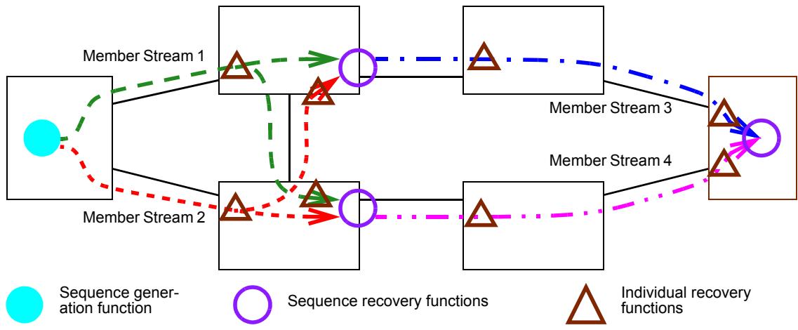
Figure 7-3—Sequence recovery functions and Individual recovery functions
7.6 Sequence encode/decode function
The Sequence encode/decode function is responsible for inserting the sequence_number subparameter (item b in 6.1) into the packet, and extracting it from the packet. If the Stream identification function (6.2) also encodes and decodes the sequence_number subparameter for a given Stream on a particular port and direction, then no Sequence encode/decode sublayer is needed. Instances of the Sequence encode/decode function are instantiated via managed objects (10.5).
The only Sequence encode/decode format specified as required, separately from any Stream identification function, is the Redundancy tag (R-TAG, 7.8). In addition, two optional formats (7.9, 7.10) are defined.
7.7 Stream splitting function
The Stream splitting function accepts a packet from the upper layers with a stream_handle subparameter (item a in 6.1), makes zero or more copies of that packet, each with a stream_handle subparameter that can be different from the original stream_handle, and passes those packets to the next-lower layer. This effectively creates Member Stream(s) from a Compound Stream. Packets passing up the stack are unchanged by the Stream splitting function.
Instances of the Stream splitting function are created to process specific Streams by means of the Stream split table (10.6) managed object. A packet passed down from the upper layers is acted upon by a Stream splitting function on a particular port (10.6.1.1) and direction (10.6.1.2) only if its stream_handle subparameter is in the frerSplitInputIdList (10.6.1.3) configured for that port and direction in some entry in the Stream split table (10.6). If the stream_handle matches any of the items in that list, then one copy of the packet is generated for each item in that same frerSplitEntry’s frerSplitOutputIdList (10.6.1.4), each copy with one of those values for its stream_handle subparameter.
7.8 Redundancy tag
The Redundancy tag (R-TAG) is an example of a Sequence encode/decode function (7.6). It operates at the frame level and can be defined using the ISS defined by IEEE Std 802.1AC, or the EISS described in 6.9 of IEEE Std 802.1Q-2014, enhanced with the extra stream_handle and sequence_number subparameters specified in 6.1. In order to instantiate the Sequence encode/decode function using the R-TAG, the frerSeqEncEncapsType managed object (10.5.1.5) is encoded using the OUI (00-80-C2) and the type values as shown in Table 10-2. The R-TAG is illustrated in Figure 7-4. The value for the EtherType for the R-TAG is given in Table 7-1.
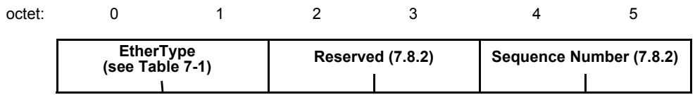
Figure 7-4—R-TAG format
When presented by the upper layers with a service request (ISS M_UNITDATA.request or EISS EM_UNITDATA.request), the Redundancy tag Sequence encode/decode function:
a) Creates an Redundancy tag information (7.8.2) word by copying the low-order 16 bits from the sequence_number subparameter to the Sequence Number field of the Redundancy tag information, and fills the Reserved field with zeros. The most-significant octet of the low-order 16 bits of the sequence_number goes in the first octet (octet 4 in Figure 7-4).
NOTE 1—Any high-order bits above the low-order 16 bits of the sequence_number subparameter are ignored.
b) Inserts an EtherType (7.8.1) and the Redundancy tag information as the first octets of the mac_service_data_unit parameter, thus increasing the size of the mac_service_data_unit parameter by 6 octets.
When presented by the lower layers with a service indication (ISS M_UNITDATA.indication or EISS EM_UNITDATA.indication), the Redundancy tag Sequence encode/decode function:
c) Examines the first two octets of the mac_service_data_unit parameter for equality with the Redundancy tag EtherType specified in 7.8.1. If it is equal, and if the mac_service_data_unit is at least 6 octets in length, then the Redundancy tag Sequence encode/decode function:
1) Removes the first 6 octets of the mac_service_data_unit, shortening it by 6 octets; and 2) Copies the Sequence Number field of the Redundancy tag information to the sequence_number subparameter, ignoring the contents of the Reserved field.
d) If the first two octets of the mac_service_data_unit parameter are not equal to the Redundancy tag EtherType, or if the mac_service_data_unit is less than 6 octets in length, then the Redundancy tag Sequence encode/decode function:
1) Sets the sequence_number subparameter to frerSeqRcvyInvalidSequenceValue (10.4.1.8).
2) Increments the frerCpsSeqEncErroredPackets and frerCpSeqEncErroredPackets managed objects (10.8.11, 10.9.3).
NOTE 2—The position of the R-TAG in a frame relative to other tags depends on the number and relative position of the Sequence encode/decode functions and other functions in the protocol stacks of the various components of a network. The managed objects in Clause 9 and Clause 10 support placing the Sequence encode/decode functions in any position to suit the needs of an application. See Clause 8 for a typical application of FRER to an IEEE 802.1Q Bridge.
7.8.1 Redundancy tag EtherType
The Tag Protocol Identifier (TPID) of the R-TAG shall use the value shown in Table 7-1.
Table 7-1—R-TAG EtherType
<table><tr><td>Purpose</td><td>EtherType</td></tr><tr><td>Redundancy tag (R-TAG)</td><td>F1-C1</td></tr></table>
7.8.2 Redundancy tag information
The R-TAG information consists of two fields:
a) The first two octets of the R-TAG information is a 16-bit Reserved field. This field shall be transmitted with all zeros and shall be ignored on receipt. It is intended that future revisions of this standard can use the most-significant bits of the Reserved field for sub-typing purposes, as described in 9.2.1 of IEEE Std 802-2014.
b) The last two octets of the R-TAG information are a 16-bit value, the Sequence Number field.
7.9 HSR sequence tag
The optional High-availability Seamless Redundancy (HSR) sequence tag is an example of a Sequence encode/decode function (7.6). It operates at the frame level and can be defined using the ISS defined by IEEE Std 802.1AC, or the EISS described in 6.9 of IEEE Std 802.1Q-2014, enhanced with the extra stream_handle and sequence_number subparameters specified in 6.1. In order to instantiate the Sequence encode/decode function using the HSR sequence tag, the frerSeqEncEncapsType managed object (10.5.1.5) is encoded using the OUI (00-80-C2) and the type values as shown in Table 10-2. The HSR sequence tag is described in 5.7.1 of IEC 62439-3:2016.
When presented by the upper layers with a service request (ISS M_UNITDATA.request or EISS EM_UNITDATA.request), the HSR sequence tag Sequence encode/decode function:
a) Creates an HSR sequence tag by:
1) Copying the low-order 16 bits from the sequence_number subparameter to the SeqNr field of the HSR sequence tag;
2) Setting the LSDU Size field in accordance with 5.7.1 of IEC 62439-3:2016;
3) Setting the PathId field according to the per-port per-Stream managed object frerSeqEncPathIdLanId (10.5.1.6); and
4) Setting the EtherType field according to 5.7.1 of IEC 62439-3:2016.
NOTE 1—Any high-order bits above the low-order 16 bits of the sequence_number subparameter are ignored.
b) Inserts the HSR sequence tag as the first octets of the mac_service_data_unit parameter, thus increasing the size of the mac_service_data_unit parameter by 6 octets.
When presented by the lower layers with a service indication (ISS M_UNITDATA.indication or EISS EM_UNITDATA.indication), the HSR sequence tag Sequence encode/decode function:
c) Examines the first two octets of the mac_service_data_unit parameter for equality with the HSR sequence tag EtherType specified in 5.7.1 of IEC 62439-3:2016. If it is equal, and if the mac_service_data_unit is at least 6 octets in length, then the HSR sequence tag Sequence encode/ decode function:
1) Removes the first 6 octets of the mac_service_data_unit, shortening it by 6 octets; and 2) Copies the SeqNr field to the sequence_number subparameter.
d) If the first two octets of the mac_service_data_unit parameter are not equal to the HSR sequence tag EtherType, or if the mac_service_data_unit is less than 6 octets in length, then the HSR sequence tag Sequence encode/decode function:
1) Sets the sequence_number subparameter to frerSeqRcvyInvalidSequenceValue (10.4.1.8).
2) Increments the frerCpsSeqEncErroredPackets and frerCpSeqEncErroredPackets managed objects (10.8.11, 10.9.3).
NOTE 2—No part of this standard is to be construed in a manner so as to alter the specifications in, or the intent of, IEC 62439-3:2016, or to restrict its future development in any way. The purpose of 7.9 is to enable the creation of interworking functions between end systems employing the R-TAG (7.8) and the HSR sequence tag.
NOTE 3—See B.2 for additional considerations when interworking between FRER and HSR.
NOTE 4—The position of the Sequence encode/decode function in the protocol stack does not need to change depending on whether the R-TAG, the HSR tag, or the PRP trailer is used.
7.10 PRP sequence trailer
The optional Parallel Redundancy Protocol (PRP) sequence trailer is an example of a Sequence encode/ decode function (7.6). It operates at the frame level and can be defined using the ISS defined by IEEE Std 802.1AC, or the EISS described in 6.9 of IEEE Std 802.1Q-2014, enhanced with the extra stream_handle and sequence_number subparameters specified in 6.1. In order to instantiate the Sequence encode/decode function using the PRP sequence trailer, the frerSeqEncEncapsType managed object (10.5.1.5) is encoded using the OUI (00-80-C2) and the type values as shown in Table 10-2. The PRP sequence trailer is described in 4.2.7.3 of IEC 62439-3:2016.
When presented by the upper layers with a service request (ISS M_UNITDATA.request or EISS EM_UNITDATA.request), the PRP sequence trailer Sequence encode/decode function:
a) Creates an PRP sequence trailer by:
1) Copying the low-order 16 bits from the sequence_number subparameter to the SeqNr field of the PRP sequence trailer;
2) Setting the LSDU Size field in accordance with 4.2.7.3 of IEC 62439-3:2016;
3) Setting the LanId field according to the per-port per-Stream managed object frerSeqEncPathIdLanId (10.5.1.6); and
4) Setting the PRPsuffix field according to 4.2.7.3 of IEC 62439-3:2016.
NOTE 1—Any high-order bits above the low-order 16 bits of the sequence_number subparameter are ignored.
b) Inserts the PRP sequence trailer as the final octets of the mac_service_data_unit parameter, thus increasing the size of the mac_service_data_unit parameter by 6 octets.
When presented by the lower layers with a service indication (ISS M_UNITDATA.indication or EISS EM_UNITDATA.indication), the PRP sequence trailer Sequence encode/decode function:
c) Examines the last two octets of the mac_service_data_unit parameter for equality with the PRP sequence trailer PRPsuffix field specified in 4.2.7.3 of IEC 62439-3:2016. If it is equal, and if the mac_service_data_unit is at least 8 octets in length, then the PRP sequence trailer Sequence encode/ decode function:
1) Removes the last 6 octets of the mac_service_data_unit, shortening it by 6 octets; and
2) Copies the SeqNr field to the sequence_number subparameter.
d) If the last two octets of the mac_service_data_unit parameter are not equal to the PRP sequence trailer EtherType, or if the mac_service_data_unit is less than 8 octets in length, then the PRP sequence trailer Sequence encode/decode function:
1) Sets the sequence_number subparameter to frerSeqRcvyInvalidSequenceValue (10.4.1.8).
2) Increments the frerCpsSeqEncErroredPackets and frerCpSeqEncErroredPackets managed objects (10.8.11, 10.9.3).
NOTE 2—No part of this standard is to be construed in a manner so as to alter the specifications in, or the intent of, IEC 62439-3:2016, or to restrict its future development in any way. The purpose of 7.10 is to enable the creation of interworking functions between end systems employing the R-TAG (7.8) and the PRP sequence trailer.
NOTE 3—See B.2 for additional considerations when interworking between FRER and PRP.
7.11 Autoconfiguration
7.11.1 Introduction to autoconfiguration
In order to satisfy the goal of Ease of use (item l in 7.1.1), there are two methods by which Stream identification functions (6.2), Individual recovery functions (7.5), Sequence recovery functions (7.4.2), and Sequence encode/decode functions (7.6) can be configured in a system:
a) Explicit configuration of entries in the Stream identity table (9.1), Sequence recovery table (10.4), Sequence identification table (10.5), and Sequence identification table (10.5); and
b) Autoconfiguration of entries in these tables using the Sequence autoconfiguration table (10.7.1) and Output autoconfiguration table (10.7.2).
Autoconfiguration can only be used with Source MAC and VLAN Stream identification (6.5) and the MatchRecoveryAlgorithm (7.4.3.5).
Whenever a packet is received that has a sequence_number subparameter encoded in a manner identified in an entry in the Sequence autoconfiguration table, but for which there is no tsnStreamIdEntry (9.1.1) in the Stream identity table, a new entry in the Stream identity table is created for the packet’s Stream, and optionally, a new entry in the Sequence recovery table for an Individual recovery function for that Stream. If a second or subsequent such Stream identity table entry is created that shares all the same key parameters as another autoconfigured tsnStreamIdEntry, except for port number (tsnStreamIdOutFacInputPortList, 9.1.1.5) and/or LanId/PathId (tsnStreamIdLanPathId, 10.2.2), then another entry in the Sequence recovery table, this time for a Sequence recovery function, is created (for the second Member Stream) or is expanded (for subsequent Member Streams) for what is now known to be a Compound Stream.
The Sequence autoconfiguration table controls whether Individual recovery functions, Sequence recovery functions, neither, or both, are created automatically. Stream identification functions are always created. If the R-TAG (7.8) is used to encode the sequence_number, entries autoconfigured in the Sequence identification table, and thus the Individual recovery functions (7.5) created, are keyed to the individual ports and VLANs on which the first packet of each Member Stream is received. If the HSR sequence tag (7.9) or PRP sequence trailer (7.10) is used, entries autoconfigured in the Sequence identification table and the autocreated Individual recovery functions are keyed to the PathId or LanId of the first-received packet of each Member Stream, and span all autoconfigurable ports.
In order to support the goals of Ease of use (item l in 7.1.1) and Interoperability (item g in 7.1.1) among systems using the HSR sequence tag (7.9), the PRP sequence trailer (7.10), and the R-TAG (7.8), passive (packet decoding) entries are also automatically created in the Sequence identification table to instantiate Sequence encode/decode functions as governed by the Sequence autoconfiguration table (10.7.1). Typically, the Output autoconfiguration table (10.7.2) is configured to construct active (packet encoding) Sequence encode/decode functions on every port on which a Stream might be output. See C.11.
7.11.2 Creating autoconfigured Stream identity table entries
NOTE 1—The following description, if implemented naïvely, might well result in a relay system delaying the transmission of the first-received packet of a Member Stream for an unacceptable length of time. The purpose of the following description is to describe the externally visible behavior of a system solely in terms of the managed objects in Clause 9 and Clause 10, not to constrain an implementation. It is expected that an actual implementation is likely to construct databases in software, firmware, and/or hardware that combine elements of the managed objects in Clause 9 and Clause 10, and to perform up-front preliminary configuration, so as to optimize the reaction time when a packet is actually received.
Autoconfiguration is triggered by the receipt of a packet that matches an entry in the Sequence autoconfiguration table (10.7.1) as follows:
a) If a packet received on an out-facing port matches an entry in the Stream identity table (9.1), it is processed according to the managed objects in 10.3, 10.4, 10.5, and 10.6.
NOTE 2—It does not matter whether the Stream identity table entry was configured explicitly, or was created via Autoconfiguration.
b) If the packet does not match any entry in the Stream identity table at all, the packet is examined to see if it matches an entry in the Sequence autoconfiguration table. A match between the packet and a frerAutSeqEntry (10.7.1.1) in the Sequence autoconfiguration table occurs if all of the following match conditions are met:
1) The packet has a sequence_number encapsulated in the manner specified by frerAutSeqSeqEncaps (10.7.1.1.1).
2) The packet was received on a port in frerAutSeqReceivePortList (10.7.1.1.2).
3) The packet’s VLAN tag (or lack thereof) matches frerAutSeqTagged (10.7.1.1.3).
4) Either the vlan_identifier parameter is in the list in frerAutSeqVlan (10.7.1.1.4), or that list is empty.
c) If the packet does not match an entry in the Sequence autoconfiguration table, no further Autoconfiguration processing takes place. Otherwise (the packet did not match any tsnStreamIdEntry, but does match a frerAutSeqEntry), Autoconfiguration processing proceeds.
d) The system creates (autoconfigures) new entries in the Stream identity table, the Sequence recovery table (10.4). and the Sequence identification table (10.5) using the matched frerAutSeqEntry as follows:
1) One new tsnStreamIdEntry (9.1.1) is created in the Stream identity table as follows:
i) tsnStreamIdHandle (9.1.1.1) = an unused stream_handle value chosen by the implementation.
ii) tsnStreamIdInFacOutputPortList (9.1.1.2) = empty.
iii) tsnStreamIdOutFacOutputPortList (9.1.1.3) = empty.
iv) tsnStreamIdInFacInputPortList (9.1.1.4) = empty.
v) If frerAutSeqSeqEncaps equals either HSR or PRP, tsnStreamIdOutFacInputPortList (9.1.1.5) = frerAutSeqReceivePortList (10.7.1.1.2). Otherwise, frerSeqRcvyPortList (10.4.1.2) = only the port on which the packet was received.
vi) tsnStreamIdIdentificationType (9.1.1.6) = 00-80-C2, 2 = Source MAC and VLAN Stream identification (6.5).
vii) tsnStreamIdAutoconfigured (10.2.1) = True.
viii) If frerAutSeqSeqEncaps equals either HSR or PRP, tsnStreamIdLanPathId (10.2.2) = the PathId or LanId field from the packet. Otherwise, tsnStreamIdLanPathId is not used.
ix) tsnCpeSmacVlanDownSrcMac (9.1.3.1) = the source_mac_address parameter of the received packet.
x) tsnCpeSmacVlanDownTagged (9.1.3.2) = frerAutSeqTagged (10.7.1.1.3.
xi) tsnCpeSmacVlanDownVlan (9.1.3.3) = the vlan_identifier parameter of the received packet.
2) If and only if frerAutSeqCreateIndividual (10.7.1.1.10) is True, a frerSeqRcvyEntry (10.4.1) is created in the Sequence recovery table (10.4) as follows:
i) frerSeqRcvyStreamList (10.4.1.1) = the stream_handle from item d:2:i, above.
ii) frerSeqRcvyPortList (10.4.1.2) = the same list as tsnStreamIdOutFacInputPortList (9.1.1.5), described in item d:2:v, above. (See C.11.)
iii) frerSeqRcvyDirection (10.4.1.3) = True (out-facing).
iv) frerSeqRcvyReset (10.4.1.4) = True. (The state machine is reset when created.)
v) frerSeqRcvyAlgorithm (10.4.1.5) = Match_Alg (00-80-C2, 1, see Table 10-1).
vi) frerSeqRcvyHistoryLength (10.4.1.6) is not used.
vii) frerSeqRcvyResetMSec (10.4.1.7) = frerAutSeqResetMSec (10.7.1.1.7).
viii) frerSeqRcvyInvalidSequenceValue (10.4.1.8) is a read-only value chosen by the system.
ix) frerSeqRcvyTakeNoSequence (10.4.1.9) = True.
x) frerSeqRcvyIndividualRecovery (10.4.1.10) = True.
xi) frerSeqRcvyLatentErrorDetection (10.4.1.11) = False.
3) One new passive frerSeqEncEntry (10.5.1) is created in the Sequence identification table to decode further received packets as follows:
i) frerSeqEncStreamList (10.5.1.1) = the stream_handle from item d:2:i, above.
ii) frerSeqEncPort (10.5.1.2) = frerAutSeqReceivePortList (10.7.1.1.2).
iii) frerSeqEncDirection (10.5.1.3) = True (out-facing).
iv) frerSeqEncActive (10.5.1.4) = False (passive).
v) frerSeqEncEncapsType (10.5.1.5) = frerAutSeqSeqEncaps (10.7.1.1.1).
vi) If frerAutSeqSeqEncaps == 00-80-C2, 2 (HSR), frerSeqEncPathIdLanId (10.5.1.6) = the PathId field of the HSR sequence tag (7.9) found in the packet. If frerAutSeqSeqEncaps == 00-80-C2, 3 (PRP), frerSeqEncPathIdLanId = the LanId field of the PRP sequence trailer (7.10) found in the packet. Otherwise, frerSeqEncPathIdLanId is not used.
If a frerSeqEncEntry with the same port list, direction, and encapsulation type is present, a new entry need not be created; the packet’s stream_handle can be added to that frerSeqEncEntry’s frerSeqEncStreamList.
4) One new active frerSeqEncEntry (10.5.1) is created in the Sequence identification table for each frerAutOutEntry (10.7.2.1) in the Output autoconfiguration table (10.7.2) to format transmitted packets for this packet’s Stream as follows:
i) frerSeqEncStreamList (10.5.1.1) = the stream_handle from item d:2:i, above.
ii) frerSeqEncPort (10.5.1.2) = frerAutOutPortList (10.7.2.1.1).
iii) frerSeqEncDirection (10.5.1.3) = True (out-facing).
iv) frerSeqEncEncapsType (10.5.1.5) = frerAutOutEncaps (10.7.2.1.2).
v) frerSeqEncPathIdLanId (10.5.1.6) = frerAutOutLanPathId (10.7.2.1.3).
If a frerSeqEncEntry with the same port list, direction, encapsulation type, and PathId/LanId is present, a new entry need not be created; the packet’s stream_handle can be added to that frerSeqEncEntry’s frerSeqEncStreamList.
e) If none of the ports to which the received packet is to be output are listed in the frerAutSeqEntry’s frerAutSeqRecoveryPortList (10.7.1.1.5), or if frerAutSeqCreateRecovery (10.7.1.1.11) is false, Autoconfiguration processing is terminated. No Sequence recovery function need be instantiated.
f) The system next scans the Stream identity table looking for a tsnStreamIdEntry that nearly matches the received packet, in order to discover whether there are other Streams similar to the received packet’s Stream such that they are all Member Streams of a Compound Stream. “Nearly matches” means that all of the following conditions are met:
1) tsnStreamIdIdentificationType (9.1.1.6) == 00-80-C2, 2 == Source MAC and VLAN Stream identification (6.5).
2) The packet’s stream_handle is not equal to tsnStreamIdHandle (9.1.1.1).
3) The source_mac_address parameter of the packet == tsnCpeSmacVlanDownSrcMac (9.1.3.1).
4) Either tsnCpeSmacVlanDownVlan (9.1.3.3) is in the frerAutSeqVlan (10.7.1.1.4) list, or that list is empty.
g) If no tsnStreamIdEntry is found that meets these criteria, then Autoconfiguration processing is terminated. No Sequence recovery function need be instantiated.
h) If a tsnStreamIdEntry is found that does meet these criteria, then either Sequence recovery functions need to be instantiated, or existing instantiations need to be modified to include the received packet’s Member Stream. To determine which, the system searches the Sequence recovery table for a frerSeqRcvyEntry that meets all of the following criteria:
1) frerSeqRcvyStreamList contains the stream_handle of the found tsnStreamIdEntry.
2) frerSeqRcvyIndividualRecovery (10.4.1.10) == False == Sequence recovery function.
3) frerSeqRcvyPortList (10.4.1.2) == frerAutSeqRecoveryPortList (10.7.1.1.5).
4) For a relay system, frerSeqRcvyDirection (10.4.1.3) is False (in-facing). For an end system, True (out-facing).
i) If the Sequence recovery table search (item h, above) is found, then the following steps are taken:
1) The packet’s stream_handle is added to the frerSeqRcvyEntry’s frerSeqRcvyStreamList (10.4.1.1).
2) If frerAutSeqLatErrDetection (10.7.1.1.12) is True, then the following steps are taken:
i) frerSeqRcvyLatentErrorPaths (10.4.1.12.3) is incremented by 1.
ii) The LatentErrorReset function (7.4.4.3) is called for the instantiation of the Latent error detection function (7.4.4) on every port in the frerSeqRcvyEntry’s frerSeqRcvyPortList (10.4.1.2).
j) Otherwise (the Sequence recovery table search in item h, above, failed to find a frerSeqRcvyEntry), a new frerSeqRcvyEntry is created as follows:
1) frerSeqRcvyStreamList (10.4.1.1) = two stream_handle values, the stream_handle from the received packet (item d:2:i, above) and the tsnStreamIdHandle (9.1.1.1) from the tsnStreamIdEntry found in item f, above.
2) frerSeqRcvyPortList (10.4.1.2) = frerAutSeqRecoveryPortList (10.7.1.1.5).
3) frerSeqRcvyDirection (10.4.1.3) = False (in-facing) for a relay system, or True (out-facing) for an end system.
4) frerSeqRcvyReset (10.4.1.4) = True. (The state machine is reset when created.)
5) frerSeqRcvyAlgorithm (10.4.1.5) = frerAutSeqAlgorithm (10.7.1.1.8).
6) frerSeqRcvyHistoryLength (10.4.1.6) = frerAutSeqAlgorithm (10.7.1.1.8). This value is not used if frerSeqRcvyAlgorithm (10.4.1.5) == Match_Alg (00-80-C2, 1, see Table 10-1).
7) frerSeqRcvyResetMSec (10.4.1.7) = frerAutSeqResetMSec (10.7.1.1.7).
8) frerSeqRcvyInvalidSequenceValue (10.4.1.8) is a read-only value chosen by the system.
9) frerSeqRcvyTakeNoSequence (10.4.1.9) = True.
10) frerSeqRcvyIndividualRecovery (10.4.1.10) = False.
11) frerSeqRcvyLatentErrorDetection (10.4.1.11) = frerAutSeqLatErrDetection (10.7.1.1.12).
12) if frerAutSeqLatErrDetection is True, then the following assignments are made:
i) frerSeqRcvyLatentErrorDifference (10.4.1.12.1) = frerAutSeqLatErrDifference (10.7.1.1.13).
ii) frerSeqRcvyLatentErrorPeriod (10.4.1.12.2) = frerAutSeqLatErrPeriod (10.7.1.1.14).
iii) frerSeqRcvyLatentErrorPaths (10.4.1.12.3) = 2.
iv) frerSeqRcvyLatentResetPeriod (10.4.1.12.4) = frerAutSeqLatErrResetPeriod (10.7.1.1.15).
k) The packet is then processed according to the newly created entries.
l) After the reception of the packet that triggers Autoconfiguration for a stream_handle, if none of the Individual recovery functions (7.5) or Sequence recovery functions (7.4.2) instantiated by a given frerAutSeqEntry (10.7.1.1) increment any packet counters (10.8) for longer than the period specified by the frerAutSeqEntry’s frerAutSeqDestructMSec (10.7.1.1.6) object, the system can destroy the state machines created by that frerAutSeqEntry.
NOTE 3—As Member Streams are found, instances of the Sequence recovery function are created, and the number of Member Flows increased to enable Latent Error Detection. If the destruct timer (frerAutSeqDestructMSec, 10.7.1.1.6) is not much larger than the normal reset period for the state machines (frerSeqRcvyResetMSec, 10.4.1.7), there is a risk that the state machines will be destroyed due to a temporary service interruption, that one or more of the Member Streams will fail to be restored after the interruption, and the purpose of Latent Error Detection will be defeated.
8 Frame Replication and Elimination for Reliability in Bridges
8.1 Limiting options
The arrangements of the various components of Time-Sensitive Networking (TSN) and Frame Replication and Elimination for Reliability (FRER) in Annex C show that the model described in Clause 6 and Clause 7 has the advantages that proper layering principles are observed, that the descriptions of the individual functions are simple, and most importantly, that the definition of a relay system’s forwarding function does not have to be modified in order to add TSN or FRER functions; all of the TSN and FRER capabilities can be provided as add-ons in the ports. However, this model offers a multitude of options for the placement of functions in an actual system. Experience shows that such flexibility is often not necessary, and if implemented naïvely, can increase the complexity of the system both for the implementor and the user.
Most of the flexibility of the model described in Clause 6 and Clause 7 can be achieved in an IEEE 802.1Q Bridge, if we limit the Bridge to two stages of activity:
1) Input transformations: An expanded port (as in, e.g., Figure C-5) that includes Sequence generation functions (7.4.1) and active upper Stream identification functions (6.6), shown in white boxes with boldface type in Figure 8-1.
2) Augmented forwarding: The Bridge Forwarding Process, described in 8.6 of IEEE Std 802.1Q-2014 (shown in white boxes in Figure 8-1), augmented with Stream identification functions (6.2, both incoming and outgoing), Sequence encode/decode functions (7.6, both incoming and outgoing), Sequence recovery functions (7.4.2), Individual recovery functions (7.5), and their associated infrastructure, all shown in shaded boxes in Figure 8-1.
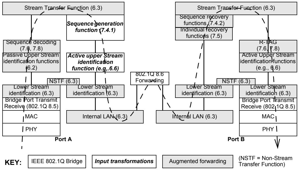
Figure 8-1—FRER functions in an FRER C-component
Item 1, Input transformations, allows the Bridge to:
a) Proxy for FRER-unaware Talkers; and
b) Perform Stream identification or Sequence encapsulation transformations on Streams entering the Bridge.
Item 2, Augmented forwarding, allows the Bridge to:
c) Serve as an intermediate sequence recovery point (e.g., system F in Figure C-4) in a network providing for multiple failures;
d) Proxy for FRER-unaware Listeners; and
e) Perform Stream identification or Sequence encapsulation transformations on Streams exiting the Bridge.
As shown in Figure 8-1, the paradigm is that a given Stream is recognized on input, meaning that the stream_handle and sequence_number subparameters are extracted. The frame is then forwarded normally through the Bridge. On the output port, the stream-handle and sequence_number subparameters found on the input port are used to drive the Individual recovery functions, Sequence recovery functions, Sequence encoding, and Stream identification functions.
Figure 8-1 does not imply that the Augmented forwarding functions have to be placed in expanded ports; they can be integrated with the Bridge forwarding function (8.6 of IEEE 802.1Q-2014) as shown in Figure 8-2. The ordering of this functions with respect to 8.6 of IEEE 802.1Q-2014 can be important. In particular:
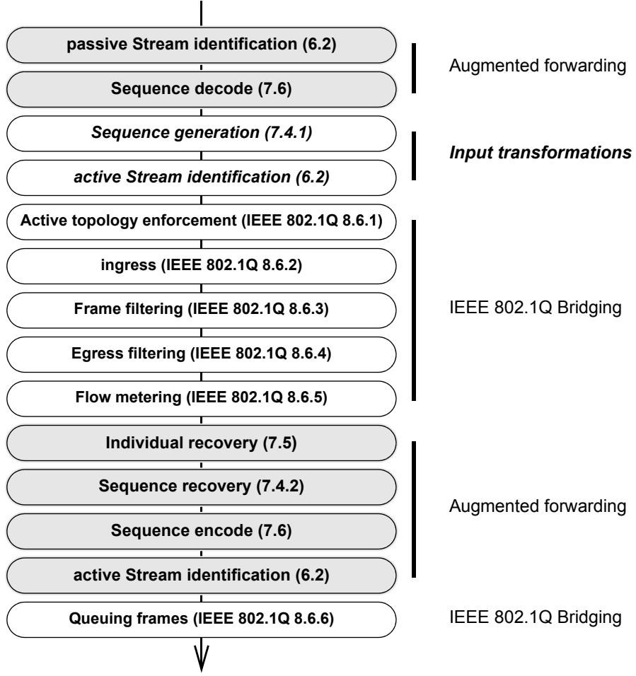
Figure 8-2—Augmented Forwarding Process does sequence recovery
f) As modeled, the stream_handle subparameter is extracted only once, on ingress. A frame is not reidentified, even if Input transformations modifies the frame.
g) As modeled, the sequence_number subparameter is not encoded into the frame during Input transformations; the final output encoding determines the frame format.
NOTE—Whether an implementation encodes the stream_handle and sequence_number subparameters into the frame’s mac_service_data_unit parameter and decodes them again after forwarding, or carries them through the forwarding process as separate subparameters, does not matter as long as the externally visible behavior conforms to that of the model.
h) If Input transformations are performed, the frame is forwarded (8.6 of IEEE Std 802.1Q-2014) according to its post-transformation parameters.
i) Flow metering (8.6.5 of IEEE Std 802.1Q-2014) is placed after the passive Stream identification function (6.2) and before the Individual recovery functions (7.5). This makes the stream_handle subparameter available for Flow metering, and means that Flow metering can be applied to the individual Streams feeding an instance of the Sequence recovery function. As a result, Flow metering can be applied to frames that will be discarded by the Individual recovery functions or Sequence recovery functions.
j) Output transformations following the Sequence recovery function take place after all forwarding (except Queuing frames, 8.6.6 of IEEE Std 802.1Q-2014). Thus, output transformations can appear to cause violations of the normal forwarding rules, e.g., Egress filtering (8.6.4 of IEEE Std 802.1Q-2014).
With the model of Figure 8-2, no explicit Stream splitting function (7.7) is required. Frames in a single Compound Stream can be replicated using the normal multicast mechanisms, and active Stream identification functions (6.2) on different output ports can cause these to be recognized as different Member Streams at the next hop. Assigning a single Sequence encode/decode function and Stream identification function to more than one stream_handle value can cause multiple Member Streams to have the same exact Stream identification method on output, and thus be merged into a single Stream, as seen by the next receiver.
In theory, if using the model of Figure 8-2, there exist instantiations of Individual recovery functions (7.5) and Sequence recovery function (7.4.2) for each distinct set of ports for which an identical set of Streams is to be output. The vector of output ports that, in principle, accompanies the packet through the IEEE 802.1Q Forwarding Process, guides the allocation of frames to these functions. After this stage, sets of Sequence encode/decode functions (7.6), and/or Stream identification functions (6.2) can be configured to further transform the packet(s).
8.2 FRER C-component input transformations
The Input transformations, marked with white boxed with boldface type in Figure 8-1, enable a Bridge to proxy for a non-FRER-capable end system. The expanded input port identifies packets belonging to a Stream (e.g., using IP Stream identification, 6.7), serializes the packets with a Sequence generation function (7.4.1), encodes the sequence number with an R-TAG (7.8), and then gives the packets belonging to this Stream a {vlan_identifier, destination_mac_address} pair that is unique, at least inside this Bridge, using Active Destination MAC and VLAN Stream identification (6.6). The IEEE 802.1Q Forwarding Process, enhanced with the Individual recovery function (7.5) and Sequence recovery function (7.4.2), then forwards the frame.
8.3 Frame Replication and Elimination for Reliability and VLAN tags
As illustrated in Figure 8-1 and Figure 8-3, FRER in an IEEE 802.1Q C-VLAN Component is above the Bridge Port Transmit and Receive function (8.5 of IEEE Std 802.1Q-2014) in the protocol stack. As a consequence of this placement, a frame containing both an IEEE 802.1Q C-VLAN tag and an R-TAG but no other IEEE 802.1Q tags, would be as illustrated in Figure 8-3.
<table><tr><td>Field</td><td>Offset</td><td>Length</td></tr><tr><td>Destination MAC address</td><td>0</td><td>6</td></tr><tr><td>Source MAC address</td><td>6</td><td>6</td></tr><tr><td>C-TAG EtherType</td><td>12</td><td>2</td></tr><tr><td>Priority, DE, VLAN ID</td><td>14</td><td>2</td></tr><tr><td>R-TAG EtherType</td><td>16</td><td>2</td></tr><tr><td>Reserved</td><td>18</td><td>2</td></tr><tr><td>Sequence number</td><td>20</td><td>2</td></tr><tr><td>Payload Length/EtherType</td><td>22</td><td>2</td></tr><tr><td>Data</td><td>24</td><td>n</td></tr><tr><td>Frame Check Sequence</td><td>24+n</td><td>4</td></tr></table>
Figure 8-3—Example Ethernet frame format
8.4 Configuring Frame Replication and Elimination for Reliability in Bridges
As described in 8.1, we can describe the output transformations, including Individual recovery functions (7.5), Sequence recovery functions (7.4.2), Sequence encode/decode functions (7.6), and Stream identification functions (6.2), as being embedded in the IEEE 802.1Q Forwarding Process. However, since different activities can be required by an application on different output ports, the managed objects in Clause 9 and Clause 10 can be used to configure an FRER C-component. Figure 8-1 illustrates an allowed arrangement of FRER functions on an output Bridge port as perceived by the managed objects in Clause 9 and Clause 10.
An FRER C-component shall implement all of the managed objects in Clause 9 and Clause 10 that are needed to meet the conformance requirements of 5.12 and 5.15 with the exceptions noted in Table 8-1.
Table 8-1—Managed objects for FRER in an FRER C-component
<table><tr><td>Variable</td><td>Reference</td><td>Limitation</td><td>Reason</td></tr><tr><td>tsnStreamIdInFacOutputPortList</td><td>9.1.1.2</td><td>Only Active Destination MAC and VLAN Stream identification (or nothing) can be configured.</td><td>Only needed for Input transformations.</td></tr><tr><td>tsnStreamIdOutFacOutputPortList</td><td>9.1.1.3</td><td>Only Active Destination MAC and VLAN Stream identification (or nothing) can be configured.</td><td>A Bridge can modify the vlan_identifier and destination_mac_address of packets belonging to a particular Stream</td></tr><tr><td>tsnStreamIdInFacInputPortList</td><td>9.1.1.4</td><td>Not allowed</td><td>There is no need to re-identify Streams on their way out of the Bridge.</td></tr><tr><td>tsnStreamIdOutFacInputPortList</td><td>9.1.1.5</td><td>No limitations</td><td>—</td></tr><tr><td>tsnCpeDmacVlanDownTagged</td><td>9.1.4.2</td><td>Not required</td><td>The decision whether to tag an outgoing frame is determined, in an IEEE 802.1Q Bridge, by other managed objects.</td></tr><tr><td>frerSeqGenDirection</td><td>10.3.1.2</td><td>Must be False (in-facing)</td><td>Sequence numbers can be added only to incoming packets.</td></tr><tr><td>frerSeqRcvyDirection</td><td>10.4.1.3</td><td>Must be False (in-facing)</td><td>Duplicate packets can be discarded only on outgoing packets.</td></tr><tr><td>frerSeqEncDirection</td><td>10.5.1.3</td><td>Must be True (out-facing)</td><td>Packets’ sequence_numbers are encoded/ decoded as they leave.</td></tr><tr><td>Stream split table</td><td>10.6</td><td>Not required</td><td>—</td></tr></table>
9 Stream Identification Management
The description of the managed objects that control Stream identification are described in the following subclauses:
a) The Stream identity table (9.1) assigns packets a stream_handle (6.1);
b) The per-port, per-Stream packet counters that are kept by Stream identification functions for inspection by network management entities are described in 9.2, and the per-port (totaled over all Streams) counters in 9.3.
The general requirements on the behavior of the Stream Identification counters in 9.2 and 9.3 are described in 10.1.
9.1 Stream identity table
The Stream identity table consists of a set of tsnStreamIdEntry objects (9.1.1), each relating to a single Stream, specifying the points in the system where Stream identification functions (6.2) are to be instantiated. Each entry in the Stream identity table has a tsnStreamIdHandle object (9.1.1.1) specifying a stream_handle value and one or more tsnStreamIdEntry objects (9.1.1) describing one identification method for that Stream. If a single Stream has multiple identification methods, perhaps (but not necessarily) on different ports, then there can be multiple tsnStreamIdEntry objects with the same value for the tsnStreamIdHandle. If the HSR or PRP method or the Sequence encode/decode function is applied to a packet, then the LanId or PathId fields are also used to identify the Stream to which the packet belongs.
9.1.1 tsnStreamIdEntry
A set of managed objects, all applying to the Stream specified by tsnStreamIdHandle (9.1.1.1), and all using the same Stream identification types and parameters (9.1.1.6, 9.1.1.7).
See 10.2 for additional managed objects that are present in the tsnStreamIdEntry only if Autoconfiguration (7.11) is used.
9.1.1.1 tsnStreamIdHandle
The objects in a given entry of the Stream identity table are used to control packets whose stream_handle subparameter is equal to the entry’s tsnStreamIdHandle object. The specific values used in the tsnStreamIdHandle object are not necessarily used in the system; they are used only to relate the various management objects in Clause 9 and Clause 10.
9.1.1.2 tsnStreamIdInFacOutputPortList
The list of ports on which an in-facing Stream identification function (6.2) using this identification method (9.1.1.6, 9.1.1.7) is to be placed for this Stream (9.1.1.1) in the output (towards the system forwarding function) direction. At most one tsnStreamIdEntry can list a given port for a given tsnStreamIdHandle in its tsnStreamIdInFacOutputPortList.
9.1.1.3 tsnStreamIdOutFacOutputPortList
The list of ports on which an out-facing Stream identification function (6.2) using this identification method (9.1.1.6, 9.1.1.7) is to be placed for this Stream (9.1.1.1) in the output (towards the physical interface) direction. At most one tsnStreamIdEntry can list a given port for a given tsnStreamIdHandle in its tsnStreamIdOutFacOutputPortList.
9.1.1.4 tsnStreamIdInFacInputPortList
The list of ports on which an in-facing Stream identification function (6.2) using this identification method (9.1.1.6, 9.1.1.7) is to be placed for this Stream (9.1.1.1) in the input (coming from the system forwarding function) direction. Any number of tsnStreamIdEntry objects can list the same port for the same tsnStreamIdHandle in its tsnStreamIdInFacInputPortList.
9.1.1.5 tsnStreamIdOutFacInputPortList
The list of ports on which an out-facing Stream identification function (6.2) using this identification method (9.1.1.6, 9.1.1.7) is to be placed for this Stream (9.1.1.1) in the input (coming from the physical interface) direction. Any number of tsnStreamIdEntry objects can list the same port for the same tsnStreamIdHandle in its tsnStreamIdOutFacInputPortList.
9.1.1.6 tsnStreamIdIdentificationType
An enumerated value indicating the method used to identify packets belonging to the Stream. The enumeration includes an Organizationally Unique Identifier (OUI) or Company ID (CID) to identify the organization defining the enumerated type. The values defined by this standard are shown in Table 9-1.
Table 9-1—Stream identification types
<table><tr><td>OUI/CID</td><td>Type number</td><td>Stream identification function</td><td>Controlling parameters</td></tr><tr><td>00-80-C2</td><td>0</td><td>Reserved</td><td>—</td></tr><tr><td>00-80-C2</td><td>1</td><td>Null Stream identification (6.4)</td><td>9.1.2</td></tr><tr><td>00-80-C2</td><td>2</td><td>Source MAC and VLAN Stream identification (6.5)</td><td>9.1.3</td></tr><tr><td>00-80-C2</td><td>3</td><td>Active Destination MAC and VLAN Stream identification (6.6)</td><td>9.1.4</td></tr><tr><td>00-80-C2</td><td>4</td><td>IP Stream identification (6.7)</td><td>9.1.5</td></tr><tr><td>00-80-C2</td><td>5–255</td><td>Reserved</td><td>—</td></tr><tr><td>other</td><td>—</td><td>Defined by entity owning the OUI or CID</td><td>—</td></tr></table>
9.1.1.7 tsnStreamIdParameters
The number of controlling parameters for a Stream identification method, their types and values, are specific to the tsnStreamIdIdentificationType (9.1.1.6) and are referenced in Table 9-1.
9.1.2 Managed objects for Null Stream identification
When instantiating an instance of the Null Stream identification function (6.4) for a particular input Stream, the managed objects in the following subclauses serve as the tsnStreamIdParameters managed object (9.1.1.7).
9.1.2.1 tsnCpeNullDownDestMac
Specifies the destination_address that identifies a packet in an EISS indication primitive, to the Null Stream identification function.
9.1.2.2 tsnCpeNullDownTagged
An enumerated value indicating whether a packet in an EISS indication primitive to the Null Stream identification function is permitted to have a VLAN tag. It can take the following values:
1) tagged: A frame must have a VLAN tag to be recognized as belonging to the Stream.
2) priority: A frame must be untagged, or have a VLAN tag with a VLAN ID = 0 to be recognized as belonging to the Stream.
3) all: A frame is recognized as belonging to the Stream whether tagged or not.
9.1.2.3 tsnCpeNullDownVlan
Specifies the vlan_identifier parameter that identifies a packet in an EISS indication primitive to the Null Stream identification function. A value of 0 indicates that the vlan_identifier parameter is ignored on EISS indication primitives.
9.1.3 Managed objects for Source MAC and VLAN Stream identification
When instantiating an instance of the Source MAC and VLAN Stream identification function (6.5) for a particular input Stream, the managed objects in the following subclauses serve as the tsnStreamIdParameters managed object (9.1.1.7).
9.1.3.1 tsnCpeSmacVlanDownSrcMac
Specifies the source_address that identifies a packet in an EISS indication primitive, to the Source MAC and VLAN Stream identification function.
9.1.3.2 tsnCpeSmacVlanDownTagged
An enumerated value indicating whether a packet in an EISS indication primitive to the Source MAC and VLAN Stream identification function is permitted to have a VLAN tag. It can take the following values:
1) tagged: A frame must have a VLAN tag to be recognized as belonging to the Stream.
2) priority: A frame must be untagged, or have a VLAN tag with a VLAN ID = 0 to be recognized as belonging to the Stream.
3) all: A frame is recognized as belonging to the Stream whether tagged or not.
9.1.3.3 tsnCpeSmacVlanDownVlan
Specifies the vlan_identifier parameter that identifies a packet in an EISS indication primitive to the Source MAC and VLAN Stream identification function. A value of 0 indicates that the vlan_identifier parameter is ignored on EISS indication primitives.
9.1.4 Managed objects for Active Destination MAC and VLAN Stream identifications
When instantiating an instance of the Active Destination MAC and VLAN Stream identification function (6.6) for a particular output Stream, the managed objects in the following subclauses, along with those listed in 9.1.2, serve as the tsnStreamIdParameters managed object (9.1.1.7).
9.1.4.1 tsnCpeDmacVlanDownDestMac
Specifies the destination_address parameter to use in the EISS request primitive for output packets sent to lower layers by the Active Destination MAC and VLAN Stream identification function, and the destination_address that identifies an input packet in an EISS indication primitive to the Active Destination MAC and VLAN Stream identification function.
9.1.4.2 tsnCpeDmacVlanDownTagged
An enumerated value indicating whether a packet in an EISS indication or request primitive between the Active Destination MAC and VLAN Stream identification function and the lower layers is to have a VLAN tag. It can take the following values:
1) tagged: An input frame must have a VLAN tag to be recognized as belonging to the Stream. An output frame receives a VLAN tag.
2) priority: An input frame must be untagged, or have a VLAN tag with a VLAN ID = 0 to be recognized as belonging to the Stream. An output frame is marked with a VLAN tag with VLAN ID = 0.
3) all: A frame is recognized as belonging to the Stream whether tagged or not. An output frame is to be untagged.
This variable is not used in an FRER C-component. See 8.4.
9.1.4.3 tsnCpeDmacVlanDownVlan
Specifies the vlan_identifier parameter to use in the EISS request primitive for output packets sent to lower layers by the Active Destination MAC and VLAN Stream identification function, and the vlan_identifier that identifies an input packet in an EISS indication primitive to the Active Destination MAC and VLAN Stream identification function. A value of 0 indicates that the vlan_identifier parameter is ignored on EISS indication primitives.
9.1.4.4 tsnCpeDmacVlanDownPriority
Specifies the priority parameter to use in the EISS request primitive for output packets sent to lower layers by the Active Destination MAC and VLAN Stream identification function for all packets in a particular Stream.
9.1.4.5 tsnCpeDmacVlanUpDestMac
Specifies the destination_address parameter to use in the EISS indication primitive for input packets offered to upper layers by the Active Destination MAC and VLAN Stream identification layer. This address replaces the address that was used to identify the packet (tsnCpeDmacVlanDownDestMac, 9.1.4.1).
9.1.4.6 tsnCpeDmacVlanUpTagged
An enumerated value indicating whether a packet in an EISS indication or request primitive between the Active Destination MAC and VLAN Stream identification function and the upper layers is to have a VLAN tag. It can take the following values:
1) tagged: An output frame must have a VLAN tag to be recognized as belonging to the Stream. An input frame receives a VLAN tag.
2) priority: An output frame must be untagged, or have a VLAN tag with a VLAN ID = 0 to be recognized as belonging to the Stream. An input frame is marked with a VLAN tag with VLAN ID = 0.
3) all: A frame is recognized as belonging to the Stream whether tagged or not. An input frame is to be untagged.
This variable is used only by an end system and not by a relay system. See 8.4.
9.1.4.7 tsnCpeDmacVlanUpVlan
Specifies the vlan_identifier parameter to use in the EISS indication primitive for packets offered to upper layers, or the VLAN ID field for an IEEE 802.1Q tag in an ISS mac_service_data_unit. This address replaces the VLAN ID that was used to identify the packet (tsnCpeDmacVlanDownVlan, 9.1.4.3).
9.1.4.8 tsnCpeDmacVlanUpPriority
Specifies the priority parameter to use in the EISS indication primitive for packets offered to upper layers.
9.1.5 Managed objects for IP Stream identification
When instantiating an instance of the IP Stream identification function (6.7), the parameters in the following subclauses replace the tsnStreamIdParameters managed object (9.1.1.7).
9.1.5.1 tsnCpeIpIdDestMac
Specifies the destination_address parameter that identifies a packet in an EISS indication primitive.
9.1.5.2 tsnCpeIpIdTagged
An enumerated value indicating whether a packet in an EISS indication or request primitive to the IP Stream identification function is to have a VLAN tag. It can take the following values:
1) tagged: An input frame must have a VLAN tag to be recognized as belonging to the Stream. An output frame receives a VLAN tag.
2) priority: An input frame must be untagged, or have a VLAN tag with a VLAN ID = 0 to be recognized as belonging to the Stream. An output frame is marked with a VLAN tag with VLAN ID = 0.
3) all: A frame is recognized as belonging to the Stream whether tagged or not. An output frame is to be untagged.
9.1.5.3 tsnCpeIpIdVlan
Specifies the vlan_identifier parameter that identifies a packet in an EISS indication primitive. A value of 0 indicates that the frame is not to have a VLAN tag.
9.1.5.4 tsnCpeIpIdIpSource
Specifies the IPv4 (RFC 791) or IPv6 (RFC 2460) source address parameter that must be matched to identify packets coming up from lower layers. An address of all 0 indicates that the IP source address is to be ignored on packets received from lower layers.
9.1.5.5 tsnCpeIpIdIpDestination
Specifies the IPv4 (RFC 791) or IPv6 (RFC 2460) destination address parameter that must be matched to identify packets coming up from lower layers.
9.1.5.6 tsnCpeIpIdDscp
Specifies the IPv4 (RFC 791) or IPv6 (RFC 2460) differentiated services codepoint (DSCP, RFC 2474) that must be matched to identify packets coming up from the lower layers. A value of 64 decimal indicates that the DSCP is to be ignored on packets received from lower layers.
9.1.5.7 tsnCpeIpIdNextProtocol
Specifies the IP next protocol parameter that must be matched to identify packets coming up from lower layers. The value of this parameter must specify either none, UDP (RFC 768), TCP (RFC 793), or SCTP (RFC 4960). If “none,” then the tsnCpeIpIdSourcePort (9.1.5.8) and tsnCpeIpIdDestinationPort (9.1.5.9) managed objects are not used.
9.1.5.8 tsnCpeIpIdSourcePort
Specifies the TCP or UDP Source Port parameter that must be matched to identify packets coming up from lower layers. A value of 0 indicates that the Source Port number of the packet is to be ignored on packets received from lower layers.
9.1.5.9 tsnCpeIpIdDestinationPort
Specifies the TCP or UDP Destination Port parameter that must be matched to identify packets coming up from lower layers. A value of 0 indicates that the Destination Port number of the packet is to be ignored on packets received from lower layers.
9.2 Operational per-port per-Stream Stream identification counters
The following counters are instantiated for each port on which the Stream identification function (6.2) is configured. The counters are indexed by port number, facing (in-facing or out-facing), and stream_handle value (tsnStreamIdHandle, 9.1.1.1). All counters are unsigned integers. If used on links faster than 650 000 000 bits per second, they shall be 64 bits in length to ensure against excessively short wrap times.
9.2.1 tsnCpsSidInputPackets
The tsnCpsSidInputPackets counter is incremented once for each packet identified by the Stream identification function (6.2).
9.2.2 tsnCpsSidOutputPackets
The tsnCpsSidOutputPackets counter is incremented once for each packet passed down the stack by the Stream identification function (6.2).
9.3 Operational per-port Stream identification counters
9.3.1 tsnCpSidInputPackets
The tsnCpSidInputPackets counter is incremented once for each packet identified by any Stream identification function (6.2) on this port. Its value equals the sum (modulo the size of the counters) of all of the tsnCpsSidInputPackets (9.2.1) counters on this same port.
9.3.2 tsnCpSidOutputPackets
The tsnCpSidOutputPackets counter is incremented once for each packet passed down the stack by any Stream identification function (6.2) on this port. Its value equals the sum (modulo the size of the counters) of all of the tsnCpsSidOutputPackets (9.2.2) counters on this same port.
10 Frame Replication and Elimination for Reliability management
The managed objects that control Stream identification are described in Clause 9. The managed objects that control FRER are described in this Clause 10 as follows:
a) General requirements on the behavior of counters are in 10.1.
b) The various tables of managed objects that can manage, in detail, each individual Stream, are described in five subclauses, including:
1) Additions (10.2) to the Stream identity table (9.1) required for Autoconfiguration (7.11, 10.7).
2) The Sequence generation table (10.3) that configures instances of the Sequence generation function (7.4.1);
3) The Sequence recovery table (10.4) that configures instances of the Individual recovery function (7.5), the Sequence recovery function (7.4.2), and the Latent error detection function (7.4.4);
4) The Sequence identification table (10.5) that configures instances of the Sequence encode/ decode function (7.6); and
5) The Stream split table (10.6) that configures instances of the Stream splitting function (7.7).
c) The managed objects that support the automatic configuration, upon receipt of a packet, of entries in the first four of the preceding tables (10.2 through 10.5), are described in the subclause on Autoconfiguration (10.7).
d) The per-port, per-Stream packet counters that are kept by FRER functions for inspection by network management entities are described in 10.8, and the per-port (totaled over all Streams) counters in 10.9.
The managed objects in the subclauses under 9.1 make it possible to configure more than one encapsulation for the same stream_handle subparameter on the same port. Similarly, the managed objects in the subclauses under 10.3 and 10.4 make it possible to configure more than one Sequence encode/decode function (7.6) or more than one Sequence generation function (7.4.1) for the same stream_handle subparameter. [The same value of stream_handle can be in the frerSeqGenStreamList (10.3.1.1) of more than one frerSeqGenEntry (10.3.1) or in the frerSeqRcvyStreamList (10.4.1.1) of more than one frerSeqRcvyEntry (10.4.1).] A system shall return an error if an attempt is made to configure conflicting requirements upon that system.
10.1 Counter behavior
All counters defined by this standard (e.g., frerCpsSeqEncErroredPackets, 10.8.11) when incremented past the maximum value representable shall roll over to 0 and continue. There is no provision for resetting any counter to any specific value, e.g., 0. A counter can be set to any value when the system is reset. This standard assumes the following:
a) Any management entity will read any counters often enough that at most one rollover can occur between examinations;
b) There exists a “time of last counter reset” or “time since last counter reset” or an equivalent managed object in the system, that the management entity can examine to determine whether the counters have been reset since the last time they were examined.
c) A counter managed object is large enough to take at least one minute to roll over from 0 to 0.
10.2 Additional tsnStreamIdEntry manged objects
Two managed objects augment each tsnStreamIdEntry (9.1.1) in the Stream identity table (9.1) when Managed objects for autoconfiguration (7.11, 10.7) is implemented.
10.2.1 tsnStreamIdAutoconfigured
A read-only Boolean value, supplied by the system, specifying whether this entry was created explicitly (False) or via the Sequence autoconfiguration table (10.7.1, True).
10.2.2 tsnStreamIdLanPathId
An integer specifying a path or LAN. If and only if a packet matches an entry in the Sequence identification table (10.5) that specifies HSR or PRP in its frerSeqEncEncapsType (10.5.1.5) object, tsnStreamIdLanPathId specifies the LanId or PathId value that must be matched for this tsnStreamIdEntry to apply. A value of –1 indicates that the LanId or PathId are to be ignored.
10.3 Sequence generation table
There is one Sequence generation table in a system, and one entry in the Sequence generation table for each Sequence generation function (7.4.1).
10.3.1 frerSeqGenEntry
Each frerSeqGenEntry lists the Streams (10.3.1.1) and direction (10.3.1.2) for which a single instance of the Sequence generation function (7.4.1) is to be placed.
10.3.1.1 frerSeqGenStreamList
A list of stream_handle values, corresponding to the values of the tsnStreamIdHandle objects (9.1.1.1) in the Stream identity table (9.1), on which this instance of the Sequence generation function (7.4.1) is to operate. The single instance of the Sequence generation function created by this frerSeqGenEntry operates every packet belonging to this Stream, regardless of the port on which it is received.
10.3.1.2 frerSeqGenDirection
A Boolean object indicating whether the Sequence generation function (7.4.1) is to be placed on the out-facing (True) or in-facing (False) side of the port (Figure 6-6).
10.4 Sequence recovery table
There is one Sequence recovery table in a system, and one entry in the Sequence recovery table for each Sequence recovery function (7.4.2) or Individual recovery function (7.5) that can also be present. The entry describes a set of managed objects for the single instance of a Base recovery function (7.4.3) and Latent error detection function (7.4.4) included in the Sequence recovery function or Individual recovery function.
10.4.1 frerSeqRcvyEntry
Each frerSeqRcvyEntry lists the Streams (10.4.1.1), ports (10.4.1.2), and direction (10.4.1.3) for which instances of a Sequence recovery function (7.4.2) or Individual recovery function (7.5) are to be instantiated.
10.4.1.1 frerSeqRcvyStreamList
A list of the stream_handle values, corresponding to the values of the tsnStreamIdHandle objects (9.1.1.1) in the Stream identity table (9.1), to which the system is to apply the instance of the Sequence recovery function (7.4.2) or Individual recovery function (7.5).
10.4.1.2 frerSeqRcvyPortList
The list of ports on each of which the system is to instantiate the Sequence recovery function (7.4.2), or from which received packets are to be fed to a single instance of the Individual recovery function (7.5).
10.4.1.3 frerSeqRcvyDirection
A Boolean object indicating whether the Sequence recovery function (7.4.2) or Individual recovery function (7.5) is to be placed on the out-facing (True) or in-facing (False) side of the port (Figure 6-6).
10.4.1.4 frerSeqRcvyReset
A Boolean object indicating that the Sequence recovery function (7.4.2) or Individual recovery function (7.5) is to be reset by calling its corresponding SequenceGenerationReset function (7.4.1.3). Writing the value True to frerSeqRcvyReset triggers a reset; writing the value False has no effect. When read, frerSeqRcvyReset always returns the value False.
10.4.1.5 frerSeqRcvyAlgorithm
This object is an enumerated value specifying which sequence recovery algorithm is to be used for this instance of the Sequence recovery function (7.4.2). The enumeration uses an OUI or CID as shown in Table 10-1. The default value for frerSeqRcvyAlgorithm is Vector_Alg (00-80-C2, 0).
Table 10-1—Enumerated values for frerSeqRcvyAlgorithm
<table><tr><td>Enumeration</td><td>OUI/CID</td><td>Type number</td><td>Sequence recovery function algorithm</td></tr><tr><td>Vector_Alg</td><td>00-80-C2</td><td>0</td><td>VectorRecoveryAlgorithm (7.4.3.4)</td></tr><tr><td>Match_Alg</td><td>00-80-C2</td><td>1</td><td>MatchRecoveryAlgorithm (7.4.3.5)</td></tr><tr><td>—</td><td>00-80-C2</td><td>2–255</td><td>Reserved</td></tr><tr><td>—</td><td>Other</td><td>—</td><td>Defined by entity owning the OUI or CID</td></tr></table>
10.4.1.6 frerSeqRcvyHistoryLength
An integer specifying how many bits of the SequenceHistory variable (7.4.3.2.2) are to be used. The minimum and the default value is 2, maximum is the maximum allowed by the implementation. [Not used if frerSeqRcvyAlgorithm (10.4.1.5) = Match_Alg (00-80-C2, 1).]
10.4.1.7 frerSeqRcvyResetMSec
An unsigned integer specifying the timeout period in milliseconds for the RECOVERY_TIMEOUT event (item c in 7.4.3.1).
10.4.1.8 frerSeqRcvyInvalidSequenceValue
A read-only unsigned integer value that cannot be encoded in a packet as a value for the sequence_number subparameter (item b in 6.1), i.e., frerSeqRcvyInvalidSequenceValue is larger than or equal to RecovSeqSpace (7.4.3.2.1).
10.4.1.9 frerSeqRcvyTakeNoSequence
A Boolean value specifying whether packets with no sequence_number subparameter are to be accepted (True) or not (False). Default value False. See item i in 7.1.1.
10.4.1.10 frerSeqRcvyIndividualRecovery
A Boolean value specifying whether this entry describes a Sequence recovery function (7.4.2) or Individual recovery function (7.5).
a) True: The entry describes an Individual recovery function (7.5). Packets discarded by the SequenceGenerationAlgorithm (7.4.1.4) will cause the variable RemainingTicks (7.4.3.2.4) to be reset. There is no Latent error detection function (7.4.4) associated with this entry, so frerSeqRcvyLatentErrorDetection (10.4.1.11) cannot also be True.
b) False: The entry describes a Sequence recovery function (7.4.2). Packets discarded by the SequenceGenerationAlgorithm (7.4.1.4) will not cause the variable RemainingTicks (7.4.3.2.4) to be reset.
10.4.1.11 frerSeqRcvyLatentErrorDetection
A Boolean value indicating whether an instance of the Latent error detection function (7.4.4) is to be instantiated along with the Base recovery function (7.4.3) in this Sequence recovery function (7.4.2) or Individual recovery function (7.5). frerSeqRcvyLatentErrorDetection cannot be set True if frerSeqRcvyIndividualRecovery (10.4.1.10) is also True; an Individual recovery function does not include a Latent error detection function.
10.4.1.12 Latent error detection managed objects
The objects in the following subclauses are present if and only if frerSeqRcvyIndividualRecovery (10.4.1.10) is False.
10.4.1.12.1 frerSeqRcvyLatentErrorDifference
An integer specifying the maximum difference between frerCpsSeqRcvyDiscardedPackets (10.8.6), and the product of frerCpsSeqRcvyPassedPackets (10.8.5) and (frerSeqRcvyLatentErrorPaths – 1) (10.4.1.12.3) that is allowed. Any larger difference will trigger the detection of a latent error by the LatentErrorTest function (7.4.4.4).
10.4.1.12.2 frerSeqRcvyLatentErrorPeriod
The integer number of milliseconds that are to elapse between instances of running the LatentErrorTest function (7.4.4.4). An implementation can have a minimum value for frerSeqRcvyLatentErrorPeriod, below which it cannot be set, but this minimum shall be no larger than 1000 ms (1 s). Default value 2000 (2 s).
10.4.1.12.3 frerSeqRcvyLatentErrorPaths
The integer number of paths over which FRER is operating for this instance of the Base recovery function (7.4.3) and Latent error detection function (7.4.4).
10.4.1.12.4 frerSeqRcvyLatentResetPeriod
The integer number of milliseconds that are to elapse between instances of running the LatentErrorReset function (7.4.4.3). An implementation can have a minimum value for LatentErrorReset, below which it cannot be set, but this minimum shall be no larger than 1000 ms (1 s). Default value 30000 (30 s).
10.5 Sequence identification table
There is one Sequence identification table per system, and one entry in the Sequence identification table for each port and direction for which an instance of the Sequence encode/decode function (7.6) is to be created.
10.5.1 frerSeqEncEntry
Each entry in the Sequence identification table specifies a port (10.5.1.2) and direction (10.5.1.3) on which an instance of the Sequence encode/decode function is to be instantiated for a list of Streams (10.5.1.1).
10.5.1.1 frerSeqEncStreamList
A list of stream_handles, corresponding to the values of the tsnStreamIdHandle objects (9.1.1.1) in the Stream identity table (9.1), for which the system is to use the same encapsulation (10.5.1.5) for the Sequence encode/decode function.
10.5.1.2 frerSeqEncPort
The port on which the system is to place an instance of the Sequence encode/decode function (7.6).
10.5.1.3 frerSeqEncDirection
A Boolean object indicating whether the Sequence encode/decode function (7.6) is to be placed on the out-facing (True) or in-facing (False) side of the port (Figure 6-6).
10.5.1.4 frerSeqEncActive
A Boolean value specifying whether this frerSeqEncEntry is passive (False), and therefore is used only to decode (extract information from) input packets passing up the protocol stack, or active (True), and therefore is used both for recognizing input packets and for encoding output packets being passed down the protocol stack.
10.5.1.5 frerSeqEncEncapsType
An enumerated value indicating the type of encapsulation used for this instance of the Sequence encode/ decode function (7.6). The type includes an OUI or CID. The values defined by this standard are shown in Table 10-2.
10.5.1.6 frerSeqEncPathIdLanId
A 4-bit integer value to be placed in the PathId field of an HSR sequence tag (7.9) or the LanId field of a PRP sequence trailer (7.10) added to an output packet. This managed object is used only if:
a) The HSR sequence tag or the PRP sequence trailer is selected by the frerSeqEncEncapsType object (10.5.1.5); and
b) frerSeqEncActive (10.5.1.4) is False (passive)
Table 10-2—Sequence Encode/Decode types
<table><tr><td>OUI/CID</td><td>Type number</td><td>Sequence encode/decode method</td></tr><tr><td>00-80-C2</td><td>0</td><td>Reserved</td></tr><tr><td>00-80-C2</td><td>1</td><td>R-TAG (7.8)</td></tr><tr><td>00-80-C2</td><td>2</td><td>HSR sequence tag (7.9)</td></tr><tr><td>00-80-C2</td><td>3</td><td>PRP sequence trailer (7.10)</td></tr><tr><td>00-80-C2</td><td>4–255</td><td>Reserved</td></tr><tr><td>Other</td><td>—</td><td>Defined by entity owning the OUI or CID</td></tr></table>
10.6 Stream split table
There is one Stream split table per system, with one frerSplitEntry (10.6.1) per Stream splitting function (7.7) per set of stream_handle values.
10.6.1 frerSplitEntry
Each entry in the Stream split table specifies a port (10.6.1.1) and direction (10.6.1.2) on which an instance of the Stream splitting function (7.7) is to be instantiated, and the list of stream_handles specifying its operation.
10.6.1.1 frerSplitPort
The port on which the system is to place an instance of the Stream splitting function (7.7) performing the stream_handle translations specified by frerSplitInputIdList and frerSplitOutputIdList (10.6.1.3, 10.6.1.4) is to be placed.
10.6.1.2 frerSplitDirection
A Boolean object indicating whether the instance of the Stream splitting function (7.7) performing the stream_handle translations specified by frerSplitInputIdList and frerSplitOutputIdList (10.6.1.3, 10.6.1.4) is to be placed on the out-facing (True) or in-facing (False) side of the port (Figure 6-6).
10.6.1.3 frerSplitInputIdList
A list of stream_handles (tsnStreamIdHandle values, 9.1.1.1) that are to be split.
10.6.1.4 frerSplitOutputIdList
A list of stream_handles (tsnStreamIdHandle values, 9.1.1.1) into which the input packet is to be split, one copy per item in the frerSplitOutputIdList.
10.7 Managed objects for autoconfiguration
10.7.1 Sequence autoconfiguration table
There is one Sequence autoconfiguration table per system. It contains any number of table entries (10.7.1.1). No two (or more) entries in the Sequence autoconfiguration table can have the same values for frerAutSeqSeqEncaps (10.7.1.1.1), frerAutSeqTagged (10.7.1.1.3), and frerAutSeqVlan (10.7.1.1.4) on any given port (10.7.1.1.2).
10.7.1.1 frerAutSeqEntry
Each frerAutSeqEntry objects (10.7.1.1) relates to a single class of Streams, and specifies how entries are created (and destroyed) in the Stream identity table (9.1), the Sequence recovery table (10.4), and the Sequence identification table (10.5).
10.7.1.1.1 frerAutSeqSeqEncaps
An enumerated value from Table 10-2, specifying which Sequence encode/decode function, and therefore, which type sequence_number encoding, is to be recognized for the purposes of Autoconfiguration.
10.7.1.1.2 frerAutSeqReceivePortList
The list of ports to which this frerAutSeqEntry applies, and on which Stream identification functions (6.2), Sequence encode/decode functions (7.6), and Individual recovery functions (7.5) are to be autocreated.
10.7.1.1.3 frerAutSeqTagged
An enumerated value indicating whether packets to be matched by this frerAutSeqEntry are permitted to have a VLAN tag. It can take the following values:
1) tagged: A frame must have a VLAN tag to be matched.
2) priority: A frame must be untagged, or have a VLAN tag with a VLAN ID = 0 to be matched.
3) all: A frame is matched whether tagged or not.
10.7.1.1.4 frerAutSeqVlan
A list of vlan_identifiers for the packet to match. A null list matches all vlan_identifiers.
10.7.1.1.5 frerAutSeqRecoveryPortList
The list of ports on which Sequence recovery functions (7.4.2) are to be autocreated by this frerAutSeqEntry.
10.7.1.1.6 frerAutSeqDestructMSec
An integer number of milliseconds after which an idle set of functions created by this frerAutSeqEntry can be destroyed. A value of 0 indicates that idle autoconfigured functions are not to be destroyed. Default value is 86 400 000 decimal (one day).
10.7.1.1.7 frerAutSeqResetMSec
The value used to fill frerSeqRcvyResetMSec (10.4.1.7) when autoconfiguring entries in the Sequence recovery table.
10.7.1.1.8 frerAutSeqAlgorithm
The value used to fill frerSeqRcvyAlgorithm (10.4.1.5) when autoconfiguring entries in the Sequence recovery table.
10.7.1.1.9 frerAutSeqHistoryLength
The value used to fill frerSeqRcvyHistoryLength (10.4.1.6) when autoconfiguring entries in the Sequence recovery table.
10.7.1.1.10 frerAutSeqCreateIndividual
A Boolean value. If True, the receipt of a packet that triggers the autoconfiguration of a new tsnStreamIdEntry also triggers the instantiation of a frerSeqRcvyEntry for an Individual recovery function.
10.7.1.1.11 frerAutSeqCreateRecovery
A Boolean value. If True, the receipt of a packet that triggers the autoconfiguration of a new tsnStreamIdEntry can also trigger the instantiation of a frerSeqRcvyEntry for a Sequence recovery function.
10.7.1.1.12 frerAutSeqLatErrDetection
A Boolean value. If True, the autoconfiguration of a new Sequence recovery function also creates an associated Latent Error Detection function.
10.7.1.1.13 frerAutSeqLatErrDifference
The value used to fill frerSeqRcvyLatentErrorDifference (10.4.1.12.1) when autoconfiguring entries in the Sequence recovery table.
10.7.1.1.14 frerAutSeqLatErrPeriod
The value used to fill frerSeqRcvyLatentErrorPeriod (10.4.1.12.2) when autoconfiguring entries in the Sequence recovery table.
10.7.1.1.15 frerAutSeqLatErrResetPeriod
The value used to fill frerSeqRcvyLatentResetPeriod (10.4.1.12.4) when autoconfiguring entries in the Sequence recovery table.
10.7.2 Output autoconfiguration table
There is one Output autoconfiguration table per system. It contains any number of frerAutOutEntry objects (10.7.2.1), each relating to a single class of Streams specifying how active entries are created in the Sequence identification table (10.5).
10.7.2.1 frerAutOutEntry
No two (or more) entries in the Output autoconfiguration table can include the same port in their frerAutSeqReceivePortList objects (10.7.1.1.2).
10.7.2.1.1 frerAutOutPortList
The list of ports to which this frerAutOutEntry applies, and on which active Sequence encode/decode functions (7.6) are to be autocreated.
10.7.2.1.2 frerAutOutEncaps
An enumerated value from Table 10-2, specifying which Sequence encode/decode function, and therefore, which type sequence_number encoding, is to be used for autoconfigured Streams on the ports in frerAutSeqReceivePortList (10.7.1.1.2).
10.7.2.1.3 frerAutOutLanPathId
An integer specifying a path or LAN. If and only if frerAutOutEncaps (10.7.2.1.2) specifies HSR or PRP frerAutOutLanPathId specifies the LanId or PathId value to be inserted into the HSR sequence tag or PRP sequence trailer of autoconfigured packets transmitted on the ports in frerAutSeqReceivePortList (10.7.1.1.2).
10.8 Operational per-port and per-Stream FRER counters
The following counters are instantiated for each port on which any of the Stream identification function (6.2), Sequencing function (7.4), or Sequence encode/decode function (7.6) is configured. The counters are indexed by port number, facing (in-facing or out-facing), and stream_handle value (tsnStreamIdHandle, 9.1.1.1). All counters are unsigned integers. If used on links faster than 650 000 000 bits per second, they shall be 64 bits in length to ensure against excessively short wrap times.
A Stream identification component (5.3) shall implement the first two counters tsnCpsSidInputPackets (9.2.1) and tsnCpsSidOutputPackets (9.2.2); the remainder of the counters in 10.8 are optional for such a system.
10.8.1 Per-Stream vs. per-Stream-per-port counters
The preceding managed objects create an instantiation of the Sequence recovery function (7.4.2) per port. In fact, a relay system can choose to create a single instance of the Sequence recovery function as part of its forwarding function, or one instance per line card, or in some other, distributed fashion, without violating the externally visible behaviors specified by this standard. The per-instantiation variables defined in Clause 7 are internal to the system, so their definitions are not affected by this choice.
However, when the algorithms of Clause 7 [e.g., the MatchRecoveryAlgorithm (7.4.3.5)] reference counters [e.g., frerCpsSeqRcvyPassedPackets (10.8.5)] defined as follows, this choice becomes important. Whenever an algorithm in Clause 7 increments a counter in the following subclauses, it increments each of the relevant counters, according to the ports on which the packet is (or would have been) output, no matter how many instantiations of the Sequence recovery function actually exist. Thus, if a duplicate packet that would have been output on ports 1, 6, and 27 is discarded by a single instantiation of the Sequence recovery function residing in a relay system’s forwarding function, three instances of the frerCpsSeqRcvyDiscardedPackets (10.8.6) counter are incremented, one for each of those ports.
10.8.2 frerCpsSeqGenResets
The frerCpsSeqGenResets counter is incremented each time the SequenceGenerationReset function (7.4.1.3) is called.
10.8.3 frerCpsSeqRcvyOutOfOrderPackets
The frerCpsSeqRcvyOutOfOrderPackets counter is incremented once for each packet accepted out-of-order by the VectorRecoveryAlgorithm (7.4.3.4) or MatchRecoveryAlgorithm (7.4.3.5). Out-of-order means that the packet’s sequence number is not one more than the previous packet received. (See item m in 7.1.1.)
10.8.4 frerCpsSeqRcvyRoguePackets
The frerCpsSeqRcvyRoguePackets counter is incremented once for each packet discarded by the VectorRecoveryAlgorithm (7.4.3.4) because its sequence_number subparameter is more than frerSeqRcvyHistoryLength (10.4.1.6) from RecovSeqNum (7.4.3.2.3).
10.8.5 frerCpsSeqRcvyPassedPackets
The frerCpsSeqRcvyPassedPackets counter is incremented once for each packet passed up the stack by the VectorRecoveryAlgorithm (7.4.3.4) or MatchRecoveryAlgorithm (7.4.3.5).
10.8.6 frerCpsSeqRcvyDiscardedPackets
The frerCpsSeqRcvyDiscardedPackets counter is incremented once for each packet discarded due to a duplicate sequence number by the VectorRecoveryAlgorithm (7.4.3.4) or MatchRecoveryAlgorithm (7.4.3.5).
10.8.7 frerCpsSeqRcvyLostPackets
The frerCpsSeqRcvyLostPackets counter is incremented once for each packet lost by the VectorRecoveryAlgorithm (7.4.3.4). A packet is counted as lost if its sequence number is not received on any ingress port.
NOTE—If per-source sequence numbering is used, frerCpsSeqRcvyLostPackets can count, as lost, packets that were sent to another destination, but not lost. See B.2.
10.8.8 frerCpsSeqRcvyTaglessPackets
The frerCpsSeqRcvyTaglessPackets counter is incremented once for each packet received by the VectorRecoveryAlgorithm (7.4.3.4) that has no sequence_number subparameter (item b in 6.1).
10.8.9 frerCpsSeqRcvyResets
The frerCpsSeqRcvyResets counter is incremented once each time the SequenceRecoveryReset function (7.4.3.3) is called.
10.8.10 frerCpsSeqRcvyLatentErrorResets
The frerCpsSeqRcvyLatentErrorResets counter is incremented once each time the LatentErrorReset function (7.4.4.3) is called.
10.8.11 frerCpsSeqEncErroredPackets
The frerCpsSeqEncErroredPackets counter is incremented once each time the Sequence encode/decode function (7.6) receives a packet that it is unable to decode successfully.
10.9 Operational per-port FRER counters
The following counters are instantiated for each port on which any of the Stream identification function (6.2), Sequencing function (7.4), or Sequence encode/decode function (7.6) is configured. The counters are indexed by port number and facing (in-facing or out-facing). All counters are unsigned integers. If used on links faster than 650 000 000 bits per second, they shall be 64 bits in length to ensure against excessively short wrap times.
A Stream identification component (5.3) shall implement the first two counters tsnCpSidInputPackets (9.3.1) and tsnCpSidOutputPackets (9.3.2); the remainder of the counters in 10.9 are optional for such a system.
10.9.1 frerCpSeqRcvyPassedPackets
The frerCpSeqRcvyPassedPackets counter is incremented once for each packet passed up the stack by the VectorRecoveryAlgorithm (7.4.3.4) or MatchRecoveryAlgorithm (7.4.3.5). Its value equals the sum (modulo the size of the counters) of all of the frerCpsSeqRcvyPassedPackets (10.8.5) counters on this same port.
10.9.2 frerCpSeqRcvyDiscardPackets
The frerCpSeqRcvyDiscardPackets counter is incremented once for each packet discarded due to a duplicate sequence number or for being a rogue packet by any VectorRecoveryAlgorithm (7.4.3.4) or MatchRecoveryAlgorithm (7.4.3.5) on this port. Its value equals the sum (modulo the size of the counters) of all of the frerCpsSeqRcvyRoguePackets (10.8.4) and frerCpsSeqRcvyDiscardedPackets (10.8.6) counters on this same port.
10.9.3 frerCpSeqEncErroredPackets
The frerCpSeqEncErroredPackets counter is incremented once each time the Sequence encode/decode function (7.6) receives a packet that it is unable to decode successfully. Its value equals the sum (modulo the size of the counters) of all of the frerCpsSeqEncErroredPackets (10.8.11) counters on this same port.
Annex A
(normative)
Protocol Implementation Conformance Statement (PICS) proforma
A.1 Introduction11
The supplier of an implementation that is claimed to conform to Clause 7 shall complete the following protocol implementation conformance statement (PICS) proforma.
A completed PICS proforma is the PICS for the implementation in question. The PICS is a statement of which capabilities and options of the protocol have been implemented. A PICS is included at the end of each clause as appropriate. The PICS can be used for a variety of purposes by various parties, including the following:
a) As a checklist by the protocol implementor, to reduce the risk of failure to conform to the standard through oversight;
b) As a detailed indication of the capabilities of the implementation, stated relative to the common basis for understanding provided by the standard PICS proforma, by the supplier and acquirer, or potential acquirer, of the implementation;
c) As a basis for initially checking the possibility of interworking with another implementation by the user, or potential user, of the implementation (note that, while interworking can never be guaranteed, failure to interwork can often be predicted from incompatible PICS);
d) As the basis for selecting appropriate tests against which to assess the claim for conformance of the implementation, by a protocol tester.
A.1.1 Abbreviations and special symbols
The following symbols are used in the PICS proforma:
<table><tr><td>M</td><td>mandatory field/function</td></tr><tr><td>!</td><td>negation</td></tr><tr><td>O</td><td>optional field/function</td></tr><tr><td>O.</td><td>optional field/function, but at least one of the group of options labeled by the same numeralis required</td></tr><tr><td>O/</td><td>optional field/function, but one and only one of the group of options labeled by the same numeralis required</td></tr><tr><td>X</td><td>prohibited field/function</td></tr><tr><td>:</td><td>simple-predicate condition, dependent on the support marked for</td></tr><tr><td>*:</td><td>AND-predicate condition, the requirement must be met if both optional items are implemented</td></tr><tr><td>++:</td><td>OR-predicate condition, the requirement must be met if either of the optional items are implemented</td></tr></table>
A.1.2 Instructions for completing the PICS proforma
The first part of the PICS proforma, Implementation Identification and Protocol Summary, is to be completed as indicated with the information necessary to identify fully both the supplier and the implementation.
The main part of the PICS proforma is a fixed-format questionnaire divided into subclauses, each containing a group of items. Answers to the questionnaire items are to be provided in the right-most column, either by simply marking an answer to indicate a restricted choice (usually Yes, No, or Not Applicable), or by entering a value or a set or range of values. (Note that there are some items where two or more choices from a set of possible answers can apply; all relevant choices are to be marked.)
Each item is identified by an item reference in the first column; the second column contains the question to be answered; the third column contains the reference or references to the material that specifies the item in the main body of the standard; the sixth column contains values and/or comments pertaining to the question to be answered. The remaining columns record the status of the items—whether the support is mandatory, optional, or conditional—and provide the space for the answers.
The supplier may also provide, or be required to provide, further information, categorized as either Additional Information or Exception Information. When present, each kind of further information is to be provided in a further subclause of items labeled A<i> or X<i>, respectively, for cross-referencing purposes, where <i> is any unambiguous identification for the item (e.g., simply a numeral); there are no other restrictions on its format or presentation.
A completed PICS proforma, including any Additional Information and Exception Information, is the protocol implementation conformance statement for the implementation in question.
Note that where an implementation is capable of being configured in more than one way, according to the items listed under Major Capabilities/Options, a single PICS may be able to describe all such configurations. However, the supplier has the choice of providing more than one PICS, each covering some subset of the implementation’s configuration capabilities, if that would make presentation of the information easier and clearer.
A.1.3 Additional information
Items of Additional Information allow a supplier to provide further information intended to assist the interpretation of the PICS. It is not intended or expected that a large quantity will be supplied, and the PICS can be considered complete without any such information. Examples might be an outline of the ways in which a (single) implementation can be set up to operate in a variety of environments and configurations; or a brief rationale, based perhaps upon specific application needs, for the exclusion of features that, although optional, are nonetheless commonly present in implementations.
References to items of Additional Information may be entered next to any answer in the questionnaire, and may be included in items of Exception Information.
A.1.4 Exceptional information
It may occasionally happen that a supplier will wish to answer an item with mandatory or prohibited status (after any conditions have been applied) in a way that conflicts with the indicated requirement. No preprinted answer will be found in the Support column for this; instead, the supplier is required to write into the Support column an X<i> reference to an item of Exception Information, and to provide the appropriate rationale in the Exception item itself.
An implementation for which an Exception item is required in this way does not conform to this standard.
Note that a possible reason for the situation described above is that a defect in the standard has been reported, a correction for which is expected to change the requirement not met by the implementation.
A.1.5 Conditional items
The PICS proforma contains a number of conditional items. These are items for which both the applicability of the item itself, and its status if it does apply—mandatory, optional, or prohibited—are dependent upon whether or not certain other items are supported.
Individual conditional items are indicated by a conditional symbol of the form “<item>:<s>” in the Status column, where “<item>” is an item reference that appears in the first column of the table for some other item, and “<s>” is a status symbol, M (Mandatory), O (Optional), or X (Not Applicable).
If the item referred to by the conditional symbol is marked as supported, then 1) the conditional item is applicable, 2) its status is given by “<s>”, and 3) the support column is to be completed in the usual way. Otherwise, the conditional item is not relevant and the Not Applicable (N/A) answer is to be marked.
Each item whose reference is used in a conditional symbol is indicated by an asterisk in the Item column.
A.1.6 Identification
A.1.6.1 Implementation identification
<table><tr><td>Supplier (Note 1)</td><td></td></tr><tr><td>Contact point for queries about the PICS (Note 1)</td><td></td></tr><tr><td>Implementation Name(s) and Version(s) (Notes 1 and 3)</td><td></td></tr><tr><td>Other information necessary for full identification—e.g., name(s) and version(s) of machines and/or operating system names (Note 2)</td><td></td></tr><tr><td colspan="2">NOTE 1—Required for all implementations.NOTE 2—May be completed as appropriate in meeting the requirements for the identification.NOTE 3—The terms Name and Version should be interpreted appropriately to correspond with a supplier's terminology (e.g., Type, Series, Model).</td></tr></table>
A.1.6.2 Protocol summary
<table><tr><td>Identification of protocol specification</td><td>IEEE Std 802.1CB-2017, IEEE Standard for Frame Replication and Elimination for Reliability</td></tr><tr><td>Identification of amendments and corrigenda to the PICS proforma that have been completed as part of the PICS</td><td>Amd: ____ Cor: _________Amd: _________ Cor: _________</td></tr><tr><td>Have any exceptions been noted? (See A.1.4. The answer, “Yes” means that the implementation does not conform to IEEE Std 802.1CB.)</td><td>Yes [ ] No [ ]</td></tr></table>
A.2 PICS proforma for Frame Replication and Elimination for Reliability
A.2.1 Major capabilities/options
<table><tr><td>Item</td><td>Feature</td><td>Subclause</td><td>Value/Comment</td><td>Status</td><td>Support</td></tr><tr><td>BG</td><td>FRER C-component implemented?</td><td>5.15</td><td></td><td>O</td><td>Yes [ ]No [ ]</td></tr><tr><td>IS</td><td>Stream identification system implemented?</td><td>5.3, 5.4, 5.5</td><td rowspan="4">One or more of IS, TE, LE, and/or RS must be answered “Yes.”</td><td>O.1</td><td>Yes [ ]No [ ]</td></tr><tr><td>TE</td><td>Talker end system implemented?</td><td>5.6, 5.7, 5.8</td><td>O.1</td><td>Yes [ ]No [ ]</td></tr><tr><td>LE</td><td>Listener end system implemented?</td><td>5.9, 5.10, 5.11</td><td>O.1</td><td>Yes [ ]No [ ]</td></tr><tr><td>RS</td><td>Relay system implemented?</td><td>5.12, 5.13, 5.14, 5.15:b, 5.15:c</td><td>BG:M + O.1</td><td>Yes [ ]No [ ]</td></tr></table>
A.2.2 Stream identification component
<table><tr><td>Item</td><td>Feature</td><td>Subclause</td><td>Value/Comment</td><td>Status</td><td>Support</td></tr><tr><td>IS1</td><td>Can the system identify frames using the Null Stream identification function?</td><td>5.3:b, 6.4</td><td></td><td>IS: M</td><td>Yes [ ]</td></tr><tr><td>IS2</td><td>Does the system implement the required managed objects of Clause 9?</td><td>5.3:c, 9</td><td></td><td>IS: M</td><td>Yes [ ]</td></tr><tr><td>IS3</td><td>Can the system encode frames using the Active Destination MAC and VLAN Stream identification?</td><td>5.4:a, 6.6</td><td></td><td>IS: O</td><td>Yes [ ]No [ ]<eq>_a</eq></td></tr><tr><td>IS4</td><td>Can the system identify packets using the IP Stream identification?</td><td>5.5:c, 6.7</td><td></td><td>IS: O</td><td>Yes [ ]No [ ]</td></tr><tr><td>IS5</td><td>For what additional Stream decodings can the system be configured?</td><td>5.5:d</td><td></td><td>IS: O</td><td>—</td></tr><tr><td>IS6</td><td>Explain the limits on which ports the above features can be configured.</td><td>5.5:a</td><td></td><td>IS: O</td><td>—</td></tr><tr><td>IS7</td><td>Explain the limits on the number of Streams for which the above features can be configured.</td><td>5.5:b</td><td></td><td>IS: O</td><td>—</td></tr></table>
a If “No,” supply a reason why.
A.2.3 Talker end system
<table><tr><td>Item</td><td>Feature</td><td>Subclause</td><td>Value/Comment</td><td>Status</td><td>Support</td></tr><tr><td>TE8</td><td>Can the system identify frames using the Null Stream identification function?</td><td>5.6:b, 6.4</td><td></td><td>TE: M</td><td>Yes [ ]</td></tr><tr><td>TE9</td><td>Can the system be configured with a Sequence generation function?</td><td>5.6:c, 7.4.1</td><td></td><td>TE: M</td><td>Yes [ ]</td></tr><tr><td>TE10</td><td>Can the system be configured with a Sequence encode/decode function?</td><td>5.6:d, 7.8</td><td></td><td>TE: M</td><td>Yes [ ]</td></tr><tr><td>TE11</td><td>Does the system implement the managed objects of Clause 9 and Clause 10 (10.7 not required)?</td><td>5.6:e, 9, 10</td><td></td><td>TE: M</td><td>Yes [ ]</td></tr><tr><td>TE12</td><td>Can the system encode frames using the Active Destination MAC and VLAN Stream identification?</td><td>5.7:a, 6.6</td><td></td><td>TE: O</td><td>Yes [ ]No [ ]<eq>_a</eq></td></tr><tr><td>TE13</td><td>Can the system be configured with a Stream splitting function?</td><td>5.7:b, 7.7</td><td></td><td>TE: M</td><td>Yes [ ]No [ ]<eq>_a</eq></td></tr><tr><td>TE14</td><td>Can the system identify packets using the IP Stream identification?</td><td>5.8:c, 6.7</td><td></td><td>TE: O</td><td>Yes [ ]No [ ]</td></tr><tr><td>TE15</td><td>For what additional Stream decodings can the system be configured?</td><td>5.8:d</td><td></td><td>TE: O</td><td>—</td></tr><tr><td>TE16</td><td>Can the system encode frames using HSR sequence tag?</td><td>5.8:e, 7.9</td><td></td><td>TE: O</td><td>Yes [ ]No [ ]</td></tr><tr><td>TE17</td><td>Can the system encode frames using PRP sequence trailer?</td><td>5.8:f, 7.10</td><td></td><td>TE: O</td><td>Yes [ ]No [ ]</td></tr><tr><td>TE18</td><td>For what additional Sequence encode/decode functions can the system be configured?</td><td>5.8:g</td><td></td><td>TE: O</td><td>—</td></tr><tr><td>TE19</td><td>Explain the limits on which ports the above features can be configured.</td><td>5.8:a</td><td></td><td>TE: O</td><td>—</td></tr><tr><td>TE20</td><td>Explain the limits on the number of Streams for which the above features can be configured.</td><td>5.8:b</td><td></td><td>TE: O</td><td>—</td></tr></table>
a If “No,” supply a reason why.
A.2.4 Listener end system
<table><tr><td>Item</td><td>Feature</td><td>Subclause</td><td>Value/Comment</td><td>Status</td><td>Support</td></tr><tr><td>LE1</td><td>Can the system identify frames using the Null Stream identification?</td><td>5.9:b, 6.4</td><td></td><td>LE: M</td><td>Yes [ ]</td></tr><tr><td>LE2</td><td>Can the system be configured with at least two Individual recovery functions?</td><td>5.9:c, 7.5</td><td></td><td>LE: M</td><td>Yes [ ]</td></tr><tr><td>LE3</td><td>Can the system be configured with at least one Sequence recovery function using the MatchRecoveryAlgorithm?</td><td>5.9:c, 7.4.2, 7.4.3.5</td><td></td><td>LE: M</td><td>Yes [ ]</td></tr><tr><td>LE4</td><td>Does the system support the Sequence recovery function using the VectorRecoveryAlgorithm with a value of frerSeqRcvyHistoryLength ≥ 2?</td><td>5.9:c, 7.4.2, 7.4.3.4</td><td></td><td>LE: M</td><td>Yes [ ]</td></tr><tr><td>LE5</td><td>Can the system be configured with at least two Individual recovery functions using the MatchRecoveryAlgorithm?</td><td>5.9:d, 7.5, 7.4.3.5</td><td></td><td>LE: M</td><td>Yes [ ]</td></tr><tr><td>LE6</td><td>Can the system be configured with a Sequence decoding function?</td><td>5.9:e, 7.8</td><td></td><td>LE: M</td><td>Yes [ ]</td></tr><tr><td>LE7</td><td>Does the system implement the managed objects of Clause 9 and Clause 10 (10.7 not required)?</td><td>5.9:f, 9, 10</td><td></td><td>LE: M</td><td>Yes [ ]</td></tr><tr><td>LE8</td><td>Does the Base recovery function process a frame before its FCS has been verified?</td><td>7.4.3</td><td></td><td>LE: M</td><td>No [ ]</td></tr><tr><td>LE9</td><td>Can the system decode frames using the Active Destination MAC and VLAN Stream identification?</td><td>5.10:a, 6.6</td><td></td><td>LE: O</td><td>Yes [ ] No [ ] _a</td></tr><tr><td>LE10</td><td>Can the system decode packets using the IP Stream identification?</td><td>5.11:c, 6.7</td><td></td><td>LE: O</td><td>Yes [ ] No [ ]</td></tr><tr><td>LE11</td><td>For what additional Stream decodings can the system be configured?</td><td>5.11:d</td><td></td><td>LE: O</td><td>—</td></tr><tr><td>LE12</td><td>Can the system decode frames using HSR sequence tag?</td><td>5.11:e, 7.9</td><td></td><td>LE: O</td><td>Yes [ ] No [ ]</td></tr><tr><td>LE13</td><td>Can the system decode frames using PRP sequence trailer?</td><td>5.11:f, 7.10</td><td></td><td>LE: O</td><td>Yes [ ] No [ ]</td></tr><tr><td>LE14</td><td>For what additional Sequence decodings can the system be configured?</td><td>5.11:g</td><td></td><td>LE: O</td><td>—</td></tr><tr><td>LE15</td><td>Can the system be configured with at least two Individual recovery functions using the VectorRecoveryAlgorithm?</td><td>5.11:h, 7.5, 7.4.3.4</td><td></td><td>LE: O</td><td>Yes [ ]</td></tr><tr><td>LE16</td><td>Explain the limits on which ports the above features can be configured.</td><td>5.11:a</td><td></td><td>LE: O</td><td>—</td></tr><tr><td>LE17</td><td>Explain the limits on the number of Streams for which the above features can be configured.</td><td>5.11:b</td><td></td><td>LE: O</td><td>—</td></tr></table>
a If “No,” supply a reason why.
A.2.5 Relay system
<table><tr><td>Item</td><td>Feature</td><td>Subclause</td><td>Value/Comment</td><td>Status</td><td>Support</td></tr><tr><td>RS1</td><td>Can the system identify frames using the Null Stream identification function?</td><td>5.12:b, 6.4</td><td></td><td>RS: M</td><td>Yes [ ]</td></tr><tr><td>RS2</td><td>Can the system be configured with a Sequence generation function?</td><td>5.12:c, 7.4.1</td><td></td><td>RS: M</td><td>Yes [ ]</td></tr><tr><td>RS3</td><td>Can the system be configured with at least two Individual recovery functions?</td><td>5.12:e, 7.5</td><td></td><td>RS: M</td><td>Yes [ ]</td></tr><tr><td>RS4</td><td>Can the system be configured with at least one Sequence recovery function using the MatchRecoveryAlgorithm?</td><td>5.12:e, 7.4.2, 7.4.3.5</td><td></td><td>RS: M</td><td>Yes [ ]</td></tr><tr><td>RS5</td><td>Does the system support the Sequence recovery function using the VectorRecoveryAlgorithm with a value of frerSeqRcvyHistoryLength ≥ 2?</td><td>5.12:e, 7.4.2, 7.4.3.4</td><td></td><td>RS: M</td><td>Yes [ ]</td></tr><tr><td>RS6</td><td>Can the system be configured with at least two Individual recovery functions using the MatchRecoveryAlgorithm?</td><td>5.12:f, 7.5, 7.4.3.5</td><td></td><td>RS: M</td><td>Yes [ ]</td></tr><tr><td>RS7</td><td>Can the system be configured with a Sequence encode/decode function?</td><td>5.12:d, 7.8</td><td></td><td>RS: M</td><td>Yes [ ]</td></tr><tr><td>RS8</td><td>Does the system implement the managed objects of Clause 9 and Clause 10 (including 10.7)?</td><td>5.12:g, 9, 10</td><td></td><td>RS: M</td><td>Yes [ ]</td></tr><tr><td>RS9</td><td>Does the Base recovery function process a frame before its FCS has been verified?</td><td>7.4.3</td><td></td><td>RS: M</td><td>No [ ]</td></tr><tr><td>RS10</td><td>Can the system encode/decode frames using the Active Destination MAC and VLAN Stream identification?</td><td>5.13:a, 6.6</td><td></td><td>RS: O</td><td>Yes [ ]No [ ]<eq>_a</eq></td></tr><tr><td>RS11</td><td>Can the system identify packets using the IP Stream identification?</td><td>5.13:b, 6.7</td><td></td><td>RS: O</td><td>Yes [ ]No [ ]<eq>_a</eq></td></tr><tr><td>RS12</td><td>For what additional Stream identification functions can the system be configured?</td><td>5.14:c</td><td></td><td>RS: O</td><td>—</td></tr><tr><td>RS13</td><td>Can the Stream splitting function be configured on the system?</td><td>5.14:d, 7.7</td><td></td><td>RS: O</td><td>Yes [ ]No [ ]</td></tr><tr><td>RS14</td><td>Can the system encode/decode frames using HSR sequence tag?</td><td>5.14:e, 7.9</td><td></td><td>RS: O</td><td>Yes [ ]No [ ]</td></tr><tr><td>RS15</td><td>Can the system encode/decode frames using PRP sequence trailer?</td><td>5.14:f, 7.10</td><td></td><td>RS: O</td><td>Yes [ ]No [ ]</td></tr><tr><td>RS16</td><td>For what additional Sequence encode/decode functions can the system be configured?</td><td>5.14:g</td><td></td><td>RS: O</td><td>—</td></tr><tr><td>RS17</td><td>Can the system be configured with at least two Individual recovery functions using the VectorRecoveryAlgorithm?</td><td>5.14:i, 7.5, 7.4.3.4</td><td></td><td>RS: O</td><td>Yes [ ]No [ ]</td></tr><tr><td>RS18</td><td>Can the system be configured for Autoconfiguration via the Managed objects for autoconfiguration?</td><td>5.14:j, 7.11, 10.7</td><td></td><td>RS: O</td><td>Yes [ ]No [ ]</td></tr><tr><td>RS19</td><td>Explain the limits on which ports the above features can be configured.</td><td>5.14:a</td><td></td><td>RS: O</td><td>—</td></tr><tr><td>RS20</td><td>Explain the limits on the number of Streams for which the above features can be configured.</td><td>5.14:b</td><td></td><td>RS: O</td><td>—</td></tr><tr><td>RS21</td><td>Explain the limits on whether the above features can be configured at in-facing or out-facing positions.</td><td>5.14:h</td><td></td><td>RS: O</td><td>—</td></tr></table>
a If “No,” supply a reason why.
A.2.6 FRER 802.1Q C-component
<table><tr><td>Item</td><td>Feature</td><td>Subclause</td><td>Value/Comment</td><td>Status</td><td>Support</td></tr><tr><td>CB1</td><td>Does the FRER 802.1QC-component conform to the required and optional behaviors required of an IEEE 802.1QC-VLAN component?</td><td>5.15:a</td><td></td><td>BG:M</td><td>Yes [ ]</td></tr><tr><td>CB1</td><td>Does the FRER 802.1QC-component conform to the placement of the FRER functions of Clause 8?</td><td>5.15:d, 8</td><td></td><td>BG:M</td><td>Yes [ ]</td></tr><tr><td>CB2</td><td>Does the FRER 802.1QC-component implement all required managed objects?</td><td>8.4</td><td></td><td>BG:M</td><td>Yes [ ]</td></tr></table>
A.2.7 Common requirements
<table><tr><td>Item</td><td>Feature</td><td>Subclause</td><td>Value/Comment</td><td>Status</td><td>Support</td></tr><tr><td>COM1</td><td>Does the R-TAG use the specified EtherType?</td><td>7.8.1</td><td></td><td>M</td><td>Yes [ ]</td></tr><tr><td>COM1</td><td>Is the Reserved field of the R-TAG transmitted as 0 and ignored on receipt?</td><td>7.1.1:d</td><td></td><td>M</td><td>Yes [ ]</td></tr><tr><td>COM2</td><td>Do all managed object counters roll over to 0 from their maximum value?</td><td>10.1</td><td></td><td>M</td><td>Yes [ ]</td></tr><tr><td>COM3</td><td>Can the system be configured with a latent error detection function?</td><td>7.4.4</td><td>Latent error detection required if sequence recovery supported</td><td>LE+RS: M</td><td>N/A [ ] Y [ ]</td></tr><tr><td>COM4</td><td>Is the minimum value for frerSeqRcvyLatentErrorPeriod no larger than 1 s?</td><td>10.4.1.12.2</td><td></td><td>LE+RS: M</td><td>N/A [ ] Y [ ]</td></tr><tr><td>COM5</td><td>Is the RemainingTicks decremented at least 100 ticks/s?</td><td>7.4.3.2.5</td><td></td><td>LE+RS: M</td><td>N/A [ ] Y [ ]</td></tr><tr><td>COM6</td><td>Does the system return an error if an attempt is made to configure conflicting requirements?</td><td>10</td><td></td><td>M</td><td>Yes [ ]</td></tr><tr><td>COM7</td><td>Is the minimum supported value of frerSeqRcvyLatentResetPeriod no larger than 1 s?</td><td>10.4.1.12.4</td><td></td><td>LE+RS: M</td><td>N/A [ ] Y [ ]</td></tr><tr><td>COM8</td><td>Are all counters 64 bits in length on links faster than 650 000 000 bits/s?</td><td>10.8, 10.9</td><td></td><td>M</td><td>N/A [ ] Y [ ]</td></tr></table>
Annex B
(informative)
Interoperability with other standards
IEC 62439-3 defines High-availability Seamless Redundancy (HSR) and the Parallel Redundancy Protocol (PRP). IEEE 802.1CB Frame Replication and Elimination for Reliability (FRER) has features that enable, though the procedures are not specified by this standard, to achieve a degree of interoperation between systems employing IEEE Std 802.1CB, and systems employing some other, similar protocol, including HSR and PRP, and RFC 3985 pseudowires (see [B4]).
B.1 Sequence number size
HSR, PRP, and pseudowires all use 16-bit sequence numbers. This standard supports the same sized sequence_number subparameter, in order to be maximally compatible.
B.2 Per-Stream versus per-source sequencing
IEC 62439-3 HSR/PRP uses one variable per source MAC address to sequence Ethernet frames. That is, frames belonging to different flows, and sent to different destinations, all share a single sequence number space. FRER, as defined in this standard, can be configured in the same way, or can be configured to generate a separate sequence number space for each Stream. For interoperability with HSR or PRP, persource sequence numbering should be configured by the user.
A problem needs to be considered if one configures a VectorRecoveryAlgorithm (7.4.3.4) to receive Intermittent Streams (item c in 7.1.1) transmitted by an HSR/PRP end system. The HSR/PRP end system uses a single sequence number, not one per Stream. If that end system is transmitting more than one Stream, and some Listener is receiving less than all of those Streams, then that Listener can observe gaps in the sequence_number subparameters of the received packets, which will be counted in frerCpsSeqRcvyLostPackets (10.8.7). For both Intermittent Streams and Bulk Streams, the Base recovery function’s frerSeqRcvyHistoryLength managed object (10.4.1.6) has to be large enough to accommodate both the delivery time difference and the maximum possible gap due to packets sent to other destinations, because packets received outside the window defined by frerSeqRcvyHistoryLength are discarded. If frerSeqRcvyHistoryLength is not large enough, duplicate packets will be delivered.
Annex C
(informative)
Frame Replication and Elimination for Reliability in systems
The building blocks described in Clause 6 and Clause 7 can be put together in many ways to achieve particular goals. A few examples are given in this annex. These examples are chosen, rather arbitrarily, to illustrate the range of applicability of FRER; they are not meant to constrain its use or to describe the only way to accomplish any given goal.
C.1 Example 1: End-to-end FRER
Illustrated in Figure C-1 is a simple network utilizing FRER for a single Compound Stream. In this example, all FRER functions are confined to the two end systems B and G. “Split” indicates that the Stream splitting function (7.7) is acting on transmitted packets. “Seq.” and “Rec.” indicate whether the Sequencing function is acting on transmitted packets (Sequence generation function, 7.4.1) or received packets (Sequence recovery function, 7.4.1, 7.4.2).
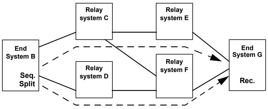
Figure C-1—Dual-homed end systems using Link Aggregation
In this example, both end systems utilize IEEE 802.1AX Link Aggregation along with FRER in order to connect their two ports (each) to a single protocol stack, as shown in Figure C-2 (end system B) and Figure C-3 (end system G). In end system B, each packet is replicated and given two different stream_handle subparameter values. The two stream_handles result in the two packets being assigned two different VLAN IDs. Based on those VLAN IDs, the two packets are both transmitted, on different physical ports, by Link Aggregation. The Distributed Resilient Network Interconnect (DRNI) feature of IEEE Std 802.1AX-2014 allows each end system’s aggregation to terminate in two relay systems.
In this example, the two-port end systems never relay packets from one port to the other; they are strictly end systems, and never act as relay systems. See C.2 and C.6 for similar examples that use alternative methods for building an end system.
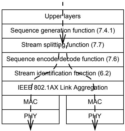
Figure C-2—Protocol stack for End System B in Figure C-1
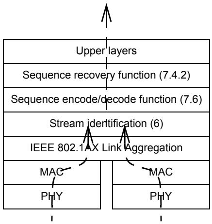
Figure C-3—Protocol stack for End System G in Figure C-1 and Figure C-4
C.2 Example 2: Various stack positions
Illustrated in Figure C-4 is a simple network utilizing FRER for a single Compound Stream, in which a relay system serves as a proxy for an end system that has no FRER capability (see item h in 7.1.1). In this figure, the numbers (1, 2, 3) are points in item e in 7.1.1. “Split” indicates that the Compound Stream is split into two streams by the ordinary bridge multicast mechanism, with the {VLAN, destination address} altered by Stream identification functions on output. [No Stream splitting function (7.7) is used.] “Seq.” and “Rec.” indicate whether the Sequencing function is acting on transmitted packets (sequence generation) or received packets (sequence recovery).
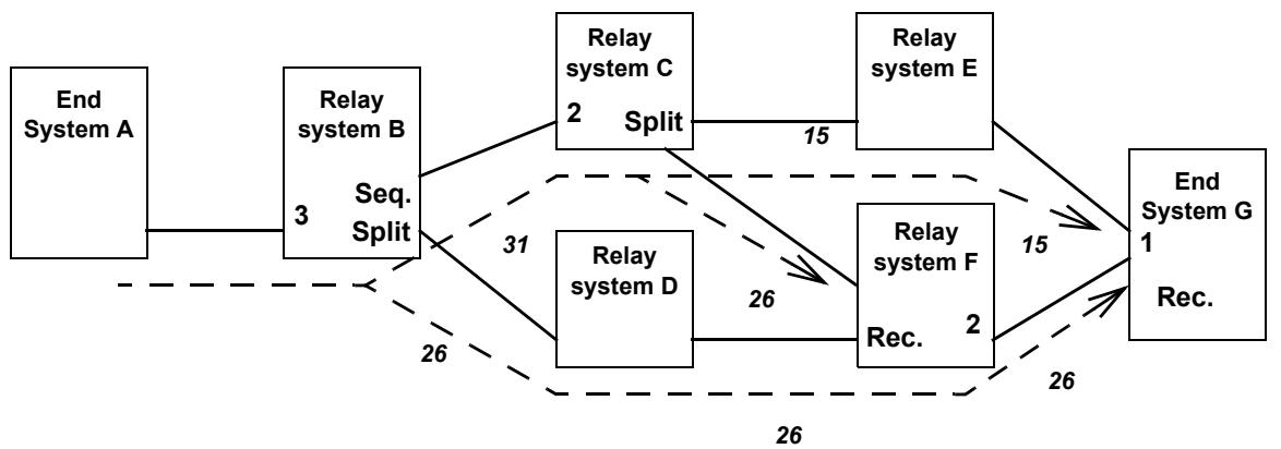
Figure C-4—Frame Replication and Elimination for Reliability flexible positioning
In Figure C-4, End System A is transmitting a Stream, but has no FRER functions. Relay system B transforms that Stream into a Compound Stream by sequencing the packets and splitting them into Member Streams 26 and 31 to go to relay systems C and D. Relay system C further splits the Stream into Streams 15 and 26 to go to relay systems E and F. (No sequencing is required; the packets were sequenced by relay system B.) Relay system F combines the two Member Streams 26 from relay systems C and D, outputting a single copy of each Packet on Stream 26 to End System G. End System G merges the two remaining Member Streams 15 and 26, and discards the extras.
NOTE—In this example, stream_handle values are shown on the wires, being relayed from system to system. This is for the convenience of the example. In an actual network, the stream_handle is an arbitrary integer that has meaning only within a system, and is mapped to or from an external representation by the Stream identification functions (6.2) in the various systems. That external representation can, but does not necessarily, include an explicit field corresponding to a stream_handle subparameter.
Figure C-5 illustrates relay system B in Figure C-4. As the packets enter from the left, from End System A, they pass first through a Stream identification function [IP Stream identification (6.7)], which identifies the Stream. The Stream Transfer Function delivers the packet with all TSN parameters, including the stream_handle subparameter, to the Sequence generation function (7.4.1, marked “Seq.” in Figure C-4), which adds a sequence_number subparameter with a steadily-increasing integer sequence value (modulo the size of the packet field carrying the sequence_number). The sequence_number subparameter is encapsulated into the packet by the Sequence encode/decode function (7.6). A Stream identification function [this time, Active Destination MAC and VLAN Stream identification (6.6)] modifies the two packets’ destination MAC addresses and VLANs for identification through the bridged network. Relay system B’s forwarding function then outputs the two packets on two different ports. The external form of the packets are labeled differently, as indicated by the italic numbers 26 and 31 in Figure C-4.
Figure C-6 illustrates relay system C in Figure C-4. The packets on Stream 31 enter from the left, from relay system B. On output, they pass first through a passive Stream identification (Clause 6) function, which identifies the Stream. The Stream Transfer Function delivers the packet with all TSN parameters, including the stream_handle subparameter, to an active Stream identification (Clause 6) function. No Sequencing function, Sequence generation function, or Sequence recovery functions are needed, because the packets have already been sequenced (by relay system B) and none are being discarded. Stream identification encapsulates the two packets differently on the two output ports (only one output port is shown in Figure C-6), marking them as belonging to Streams 15 and 26, and relay system C’s forwarding function outputs the two packets on two different ports.
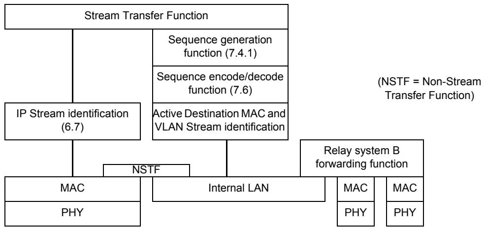
Figure C-5—Protocol stack for relay system B, proxying for End System A, in Figure C-4
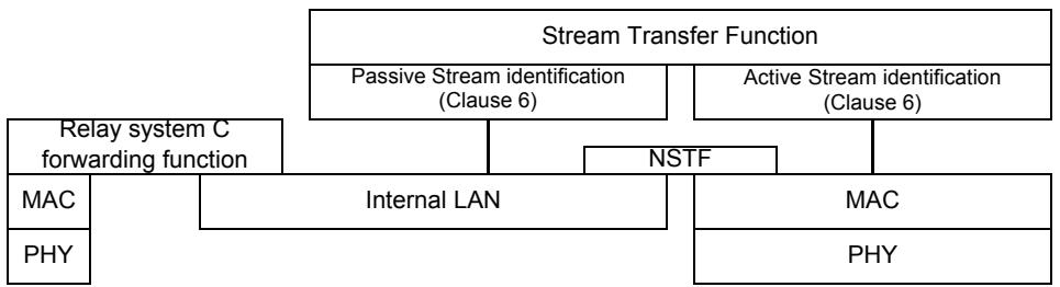
Figure C-6—Protocol stack for relay system C in Figure C-4
Figure C-7 illustrates relay system F in Figure C-4. In this case, the TSN layers are on the output port, rather than the input port, as was the case for relay system B. Data packets from both Streams 26 are brought together simply by the fact that they are both output to the same port. On that port, the Stream identification function gives them both the same stream_handle subparameter, effectively merging them into a single Stream. A Sequence encode/decode function (7.6) extracts the sequence_number subparameters from the packets, so that the Sequence recovery function (7.4.2) can discard the replicates. The Stream Transfer Function delivers all of these parameters to a Sequencing function and a Stream identification function that re-encapsulate the packets, marking them all as belonging to Stream 26, the same as when they were received. In this particular example, unlike Figure C-5, no translation of Stream identification functions is being performed.
Finally, the protocol stack in the right-hand End System G of Figure C-4 is shown in Figure C-3. We assume in this example that relay systems E and F use IEEE 802.1AX Distributed Resilient Network Interface (DRNI), and that End System G uses IEEE 802.1AX Link Aggregation, in order to make End System G’s two physical ports appear, to the network, to be a single port, even though they are connected to two different relay systems. The packets on Streams 15 and 26 are brought together by Link Aggregation. The Stream identification function assigns the same stream_handle subparameter to packets of both Streams, effectively merging them into a single Stream. They then pass through the Sequence recovery function, which deletes the replicates for delivery to the upper layers. See Figure C-2 for a similar example of a Talker, and C.6 for another type of two-port end system.
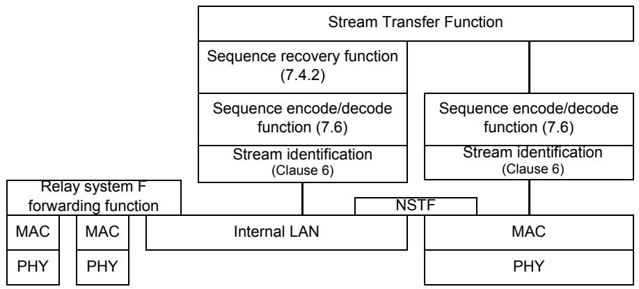
Figure C-7—Protocol stack for relay system F in Figure C-4
C.3 Example 3: Ladder redundancy
Illustrated in Figure C-8 is a network implementing “ladder redundancy.” This network will continue to function in the face of multiple failures, because the Stream is repeatedly split and remerged.
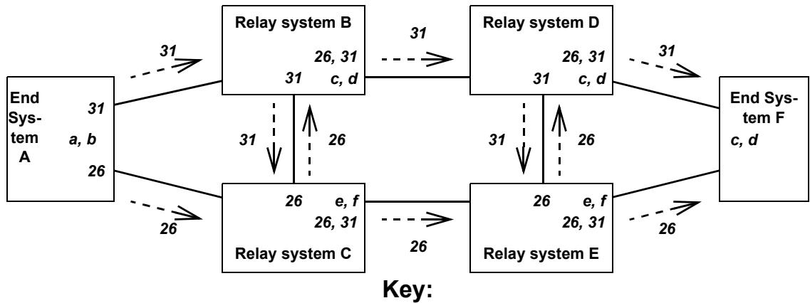
a: Add sequence numbers to Stream 31.
b: Split Stream 31 into Streams 26 and 31.
c: Merge Streams 26 and 31 into Stream 31.
d: Eliminate duplicates on Stream 31.
e: Merge Streams 26 and 31 into Stream 26.
f: Eliminate duplicates on Stream 26.
Each system’s output ports marked with
Streams transmitted and functions performed.
Figure C-8—Ladder redundancy
In Figure C-8, the Talker end system sequences Stream 31, then splits it into two Streams 26 and 31, sending one on each of its two ports. The network “ladder” has two “rails,” an upper (relay systems B and D) and a lower (relay systems C and E). The “rungs” are the connections B–C and D–E. Each relay system sends the Stream received on the rail from the left both to the right, along the rail, and up or down, over the rung. It forwards the packets received from the rung only to the right, along the rail. At each output port to the rail, the end systems have a Sequence recovery function (7.4.2) to eliminate duplicates.
Each of the relay systems in Figure C-8 uses the protocol stack illustrated in Figure C-7.
C.4 Example 4: Multicast trees
Illustrated in Figure C-9 is a multicast FRER application. Each Stream is a multicast Stream. There are two paths to get from the Talker to each Listener; no single failure can disrupt both paths to any relay system. Presumably, each relay system has a Sequence recovery function (7.4.2) on each port to each Listener, so that each Listener receives only one copy of each packet of the Stream.
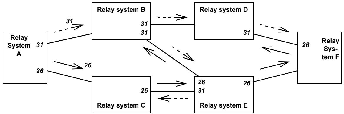
Key:
Each port is labeled with the Stream that it outputs. Every relay system receives Stream 26 and Stream 31 on a different port.
Figure C-9—Multicast trees
NOTE—The reader may find it informative to see that not all packets are replicated on all links in Figure C-9. It is not necessary to use each link twice; it is only necessary to get each packet to each relay system twice.
C.5 Example 5: Protocol interworking
Figure C-10 illustrates a simple protocol interworking function in one port of a relay system. In this example, two different encapsulation schemes 1 and 2 are used for the two legs of the Stream Transfer Function, so that packets are transformed from using one encapsulation to using the other encapsulation as they pass through the port. No additional functions, e.g., a Sequence recovery function (7.4.2) are shown, although they would be perfectly admissible. If this were a port of a bridge attached to an end system, encapsulation 1 could be the Active Destination MAC and VLAN Stream identification (6.6), and encapsulation 2 could be the IP Stream identification (6.7). The net result for the end system could be to convert a specific unicast IP Stream to use a specific multicast destination address and VLAN, in order to direct the packet through a specific path through the bridged network. Presumably, a similar interworking pair at the other end of the Stream would restore the packet to its original destination MAC address and VLAN.
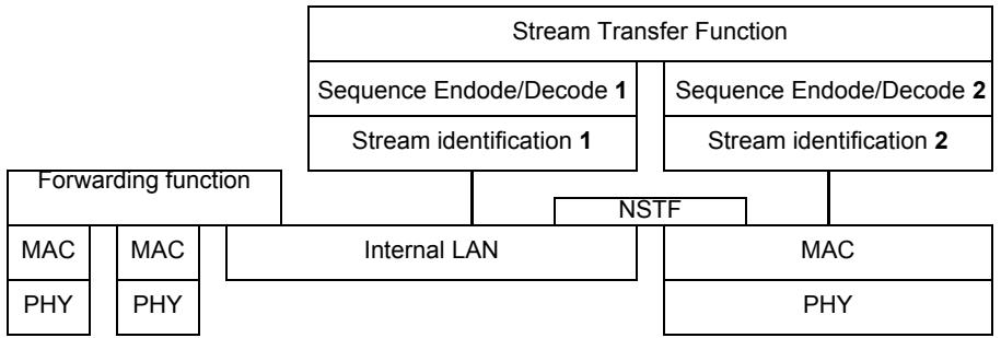
Figure C-10—Protocol interworking
C.6 Example 6: Chained two-port end systems
Illustrated in Figure C-11 is a simple network utilizing FRER for a single Compound Stream. In this example, all FRER functions are confined to the two end systems B and G. “Seq.” and “Rec.” indicate whether the Sequencing function is acting on transmitted packets (sequence generation) or received packets (sequence recovery). In this example, unlike that in C.1, both end systems are composite systems; each uses a separate one-port end system (B1, G1) attached to a three-port FRER C-component (B2, G2) in order to connect their two ports (each) to a single protocol stack, as shown in Figure C-12.
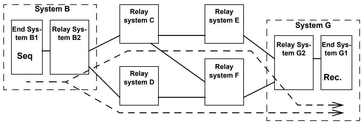
Figure C-11—Dual-homed end systems using 3-port bridge
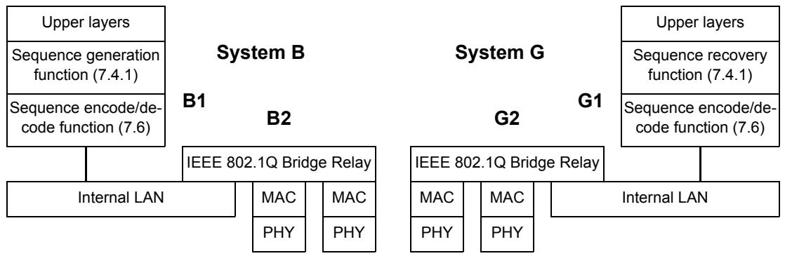
Figure C-12—Protocol stacks for Systems B and G in Figure C-11
In this example, we assume that the relay systems are all FRER C-components, and that the network has been configured so that:
a) The Stream packets carry a multicast destination MAC address;
b) Bridge B2 has been configured to transmit the (multicast) Member Stream on both ports; and
c) The other Bridges, especially G2, have been configured to allow both Member Streams to enter Bridge G2, but that Bridge G2 passes the Stream to end system G1 only (that is, the normal rules for a multicast tree are broken).
Given this configuration, no Stream splitting function (7.7) is necessary for end system B1; packet duplication is handled by the multicast forwarding functions performed in its associated relay system B2.
Unlike the example in C.1, the two-port composite end systems’ Bridge functions (B2, G2) are required to play their part in the network as Bridges, operating protocols and forwarding packets.
C.7 Cautions
Explicit path creation carries a clear danger when combined with automatic network forwarding, e.g., as defined by IEEE Std 802.1Q. Figure C-13 shows an explicit tree (the dashed arrows) established in relay system D that sends a particular Stream to relay system B and end system F. (Perhaps, at one time, the Talker was attached to relay system D and the Listeners were towards B and F.) Now, end system A starts transmitting that Stream along an IEEE 802.1Q spanning tree. When the Stream hits relay system D, it is directed back to relay system B, and the Stream loops, multiplying the packets until the bandwidth is saturated. Note also that, if this is a bridged network, relay system B (a bridge) learns conflicting information about the path to the Stream’s source; System A’s source MAC address is being received both from end system A and relay system D.
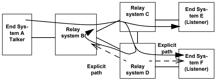
Figure C-13—Explicit path causing a loop
In order to avoid this situation in a bridged network, the application or individual that sets up the explicit paths can configure them so that they are kept, end-to-end, on separate VLANs from traffic that is not following explicit paths. On the explicit path VLANs, source learning is not performed, and destination addresses not found in the filtering database are discarded, not flooded.
C.8 Balancing tag insertion and removal
A Sequence encode/decode function will often add something to a packet. The R-TAG described in 7.8, for example, adds six octets. In a network in which not all end systems contain a Sequence encode/decode function (7.6), instances of that function can be configured in relay systems adjacent to the end systems lacking the layer, in order to remove the extra information (e.g., the R-TAG) from the packets before delivery to the end system. If the tag is not removed, and the end system has no Sequence encode/decode function, the end system will be unable to parse the received packet. It is up to the network administrator and/or configuration and management software to make sure that this does not happen.
C.9 FRER and reserved bandwidth
Satisfying the Zero congestion loss goal (item k in 7.1.1) can require the forwarding of packets to be delayed. The problem is that the different paths taken by packets in a Compound Stream can take different times to reach various Sequence recovery functions (7.4.2). If these times are very different, and if the faster path fails and then recovers, the receiving Sequence recovery function can be presented with a double-rate load of packets that all have to be delivered.
As an example, Figure C-14 illustrates a network with two Member Streams being merged into a single Stream by a Sequence recovery function. The two paths are of different lengths such that, typically, there are 40 more packets in flight on one path than on the other.
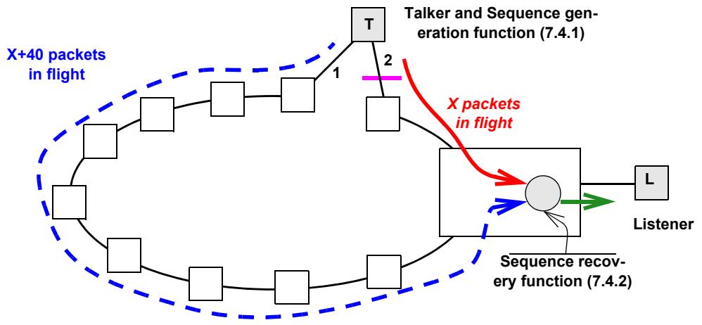
Figure C-14—Example of Long and short paths
Let us examine a hypothetical sequence of events as Link 2 in Figure C-14 fails, and then recovers. In the following list, the sequence numbers of packets taking the path through Link 2 (the short path) are in italics, and packets that are discarded by the Sequence recovery function are marked with asterisks (*).
a) The network is in a steady state. The Sequence recovery function receives packets:
$$
1 0 4 0, 1 0 0 0 ^ {*}, 1 0 4 1, 1 0 0 1 ^ {*}, 1 0 4 2, 1 0 0 2 ^ {*}, \dots
$$
That is, excepting the occasional random packet loss (not shown), the packets taking the short path (Link 2) are passed on, and those taking the long path (Link 1) are discarded.
b) Link 2 fails sometime later (4000 packets later). The Sequence recovery function receives:
$$
5 0 4 0, 5 0 0 0 ^ {*} (\text { failure occurs }), 5 0 0 1 ^ {*}, 5 0 0 2 ^ {*}, \dots
$$
That is, for a while at least, no packets are passed on; those in the slow path have already been seen.
c) The discards continue with no packets passed until the backlog on the slow path is emptied:
$$
5 0 3 8 ^ {*}, 5 0 3 9 ^ {*}, 5 0 4 0 ^ {*}, 5 0 4 1, 5 0 4 2, 5 0 4 3, \dots
$$
Normal output rates then resume, with all packets coming from the long path (Link 1).
d) When the short path (Link 2) heals (3000 packets later), the Sequence recovery function receives:
$$
7 9 9 8, 7 9 9 9, (\text { link heals }) 8 0 4 0, 8 0 0 0, 8 0 4 1, 8 0 0 1, 8 0 4 2, 8 0 0 2, \dots
$$
Note that the Sequence recovery function is now passing packets at twice the normal rate, until the 40-packet backlog on the long (Link 1) path has been passed along.
e) Finally, the backlog is exhausted, and the Sequence recovery function resumes the normal output
$$
\text { rate, passing packets from the short path (Link 2) and discarding those from the long path (Link 1): }
$$
$$
\begin{array}{l} 8 0 7 8, 8 0 3 8, 8 0 7 9, 8 0 3 9, 8 0 8 0, 8 0 4 0 ^ {*}, 8 0 8 1, 8 0 4 1 ^ {*}, 8 0 8 2, 8 0 4 2 ^ {*}, \dots \end{array}
$$
Zero congestion loss goal (item k in 7.1.1) can require that packets be output to the Listener at a fixed maximum rate over some observation interval smaller than the transmission time of this 80-packet burst. (See, for example, Clauses 34 and 35 of IEEE Std 802.1Q-2014.) In that case, some means of buffering, and thus delaying the packets in this burst, is required at or near the Sequence recovery function.
This buffering and/or delaying is beyond the scope of this standard. We can observe, however, that the extra buffering required by FRER in order to prevent congestion loss when bandwidth reservation is employed, due to this problem, can be calculated separately from the buffering required for the non-FRER case, based on the bandwidth of the Compound Stream and the difference in worst-case delivery latency along the two (or more) Member Streams’ paths.
C.10 Use of the Individual recovery function
The Individual recovery function is described in 7.5, and a sample network employing the Individual recovery function is illustrated in Figure 7-3. The primary use of the Individual recovery function is to prevent stale data from being transmitted in the event that one of the Member Streams of a Compound Stream fails such that the same packet is sent over and over again. Imagine, in Figure 7-3, that the leftmost system fails on its upper port, resending the packet with sequence_number 5 over and over again on Member Stream 1. The Sequence recovery functions (7.4.2) in the two systems receiving the Member Streams 1 and 2 will discard the repeated packets until the sequence_number subparameter on the good Member Stream 2 wraps around after 65 536 packets. Then, whichever packet 5 is received first will be relayed to the next stage. It could be the new, good, Member Stream 2’s packet 5 or the old, bad, Member Stream 1’s packet 5. If Individual recovery functions are configured for Member Stream 1 as shown by the triangles in the two systems receiving that Stream, then all of the packet 5s after the first will be discarded there, and never reach the Sequence recovery functions.
C.11 Use of autoconfiguration
Every last detail of the operation of FRER on each individual Stream can be configured by using the managed objects in Clause 9 and Clause 10. Often, however, there is enough regularity in the use of FRER across various Streams in a network that Autoconfiguration (7.11) can be used. There are four steps to using Autoconfiguration in a given relay system or end system, as follows:
a) Deciding on which port(s) packets belonging to Member Streams will be received and transmitted, using what translations are required that do not use active Stream identification functions (C.11.1).
b) Deciding which packets can trigger Autoconfiguration (C.11.2).
c) Deciding which method for encoding the sequence_number subparameter will be used for input and output on each port (C.11.3).
d) Deciding on whether Individual recovery functions, Sequence recovery functions, or both, are to be automatically instantiated, and what controlling parameters are to be used for each instantiation (C.11.4).
NOTE—Although the following examples describe interoperation between HSR/PRP and the R-TAG, such interoperability is not the primary reason for defining autoconfiguration. Autoconfiguration greatly simplifies the amount of configuration required for networks that use only the R-TAG.
C.11.1 Routing and labeling Member Streams
Figure C-15 illustrates an example network with four Member Streams constituting a Compound Stream. This example is similar to that illustrated in Figure 7-3.
In general, the selection of paths taken by Member Streams through the network is not determined by FRER, but by other standards. Autoconfiguration does not provide a means of establishing active Stream identification functions to perform per-Stream identification transformations. In Figure C-15, let us assume for the sake of example that Member Stream 1 and Member Stream 2 both have the same destination MAC address, but are on two special VLANs 1000 and 1001, used exclusively in this network for fully managed pinned-down paths. That is, these two VLANs are not controlled by the topology protocols defined in IEEE Std 802.1Q. Let us further suppose that Member Stream 3 and Member Stream 4 are similar, but both use the same VLANs 2000. (Presumably, source address learning is disabled on this VLAN.)
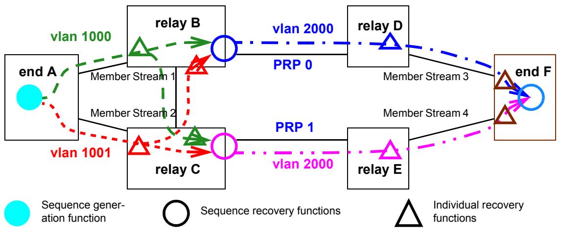
Figure C-15—Autoconfiguration example
Looking at relay system B in Figure C-15, we can see that all packets in Member Stream 3 are to be output on VLAN 2000 with a PRP sequence trailer specifying LanId 0. That means that packets from Member Streams 1 and 2 that are accepted by the Sequence recovery function in relay system B must be translated from VLAN 1000 or 1001 to VLAN 2000. The Autoconfiguration facility of 7.11 does not automatically setup or change vlan_identifiers. Relay system B must be configured to perform a VLAN ID translation on its right-hand port, translating both VLAN 1000 and VLAN 1001 to VLAN 2000 on output. If there are a great many Compound Streams, then presumably they would share the same VLAN assignments and thus make use of the same VLAN translations. IEEE 802.1Q bridges have such a VLAN ID translation capability.
Although not shown in Figure C-15, we can imagine that there are Streams with Talkers in the right side of the figure and listeners on the left. Additional VLAN mapping would then be required on the left and bottom ports of relay system B to map VLAN 2000 to VLAN 1000 and VLAN 1001. If the VLAN situation were significantly more complex, then the network might not be suitable for Autoconfiguration.
C.11.2 Recognizing packets that trigger autoconfiguration
In the example in Figure C-15, let us consider only relay system B, and only packets that follow the same routes as Member Streams 1 and 2. In that case, we expect relay system B to receive packets suitable for Autoconfiguration only on its left and bottom ports, all encoded with the R-TAG (7.8). Thus, an administrator would construct a frerAutSeqEntry (10.7.1.1) in the Sequence autoconfiguration table specifying that tag on those ports, for VLANs 1000 and 1001. This entry will, when a matching packet is received, create a tsnStreamIdEntry (9.1.1) in the Sequence identification table (10.5) using Source MAC and VLAN Stream identification (6.5). Since the R-TAG contains no indication as to which Member Stream a packet belongs, the entry is tied to the port and VLAN on which the packet was received. In this way, all of the Member Streams from end system A that take the path of Member Stream 1 are assigned one stream_handle, and all those following the path of Member Stream 2 get a second stream_handle.
Again, we can imagine that there are Streams with Talkers in the right side of Figure C-15 and listeners on the left. A second frerAutSeqEntry is required in the Sequence autoconfiguration table is required to recognize, for Autoconfiguration, the packets coming in on relay system B’s right-hand port, and create entries in the Sequence identification table. This single entry specifies packets encoded with the PRP sequence trailer (see a further explanation of this in C.11.3), and includes all PRP ports—in this example, just the one. A tsnStreamIdEntry created for HSR or PRP by this entry that assigns packets a stream_handle would not be tied to the port and VLAN on which the packet was received, but to all ports covered by the tsnStreamIdEntry, and to the LanId or PathId contained in the packet. That is, the contents of the HSR sequence tag or the PRP sequence trailer override the port number.
C.11.3 Per-port packet decoding and encoding
The example in Figure C-15 also illustrates a second use of Autoconfiguration. In this network, everything to the right of relay systems B and C, including the rightmost ports on relay systems B and C, use the PRP sequence trailer (7.10), whereas all ports on relay systems A, B, and C to the left use the R-TAG (7.8). Packets transmitted to the right by relay system B, and all packets transmitted by system D and the upper port of system F are marked as being on LanId 0, and by other ports on the right side of the figure as being on LanId 1. Packets transmitted by any other port on relay systems B and C, or by system A, use the R-TAG. These distinctions are made using the Output autoconfiguration table (10.7.2). Using this table, each port is assigned an output encapsulation, including the LanId or PathId for PRP or HSR, respectively. Again, if the usage is too complex (e.g., one Stream is LanId 0 on a port, while another is LanId 1 on that same port), Autoconfiguration cannot be used.
Note that the administrator could configure the Sequence autoconfiguration tables and Output autoconfiguration tables in relay systems D and E to translate among the R-TAG, the HSR sequence tag, and the PRP sequence trailer for the purpose of interworking, even if no Individual recovery functions or Sequence recovery functions were desired in those relay systems.
C.11.4 Individual and Sequence recovery functions
Given the explanations in C.11.1, C.11.2, and C.11.3, the reader can consult 7.11.2 to understand how Individual recovery functions and Sequence recovery functions are configured as a result of Autoconfiguration. They are set up, along with the input (passive) Stream identification functions, by entries in the Sequence autoconfiguration table (10.7.1). The reader may find the following facts helpful:
a) At most one instance of the Individual recovery function is instantiated for each stream_handle associated with an autocreated tsnStreamIdEntry (9.1.1).
a) One instance of the Sequence recovery function is instantiated on each expected output port (frerAutSeqRecoveryPortList, 10.7.1.1.5) for each Compound Stream.
b) Compound Streams are inferred by associating Member Streams with the same Source MAC address and VLAN ID.
Annex D
(informative)
Bibliography
Bibliographical references are resources that provide additional or helpful material but do not need to be understood or used to implement this standard. Reference to these resources is made for informational use only.
[B1] IEEE Std 802.1BA™-2011, IEEE Standard for Local and Metropolitan Area Networks—Audio Video Bridging (AVB) Systems.12, 13
[B2] IEEE Std 802.3™, IEEE Standard for Ethernet.
[B3] IEEE Std 1722™-2016, IEEE Standard for a Transport Protocol for Time-Sensitive Applications in Bridged Local Area Networks.
[B4] IETF RFC 3985, Bryant, S., Ed., and P. Pate, Ed., Pseudo Wire Emulation Edge-to-Edge (PWE3) Architecture, DOI 10.17487/RFC3985, March 2005.14
Consensus
WE BUILD IT.
Connect with us on:
Facebook: https://www.facebook.com/ieeesa
Twitter: @ieeesa
Linkedln: http://www.linkedin.com/groups/IEEESA-Oficial-IEEE-Standards-Association-1791118
IEEE-SA Standards Insight blog: htp://standardsinsight.com
YouTube: IEEE-SA Channel